

Page 1
XT302C Deluxe Programmable
5 FEET
[1.5 METERS]
YES
NO
NO
NO
M17106
Heat-Cool Thermostat
18-HD25D7-5
INSTALLER'S GUIDE
APPLICATION
The XT302C Deluxe Programmable Heat-Cool Thermostat provides electrnic control of 24 Vac single-zone multistage systems.
Refer to Table 1 for a general description of the thermostat. This thermostat requires a common wire to supply power.
Table 1. Description of XT302C.
Model System Changeover System Selection Fan Selection Comments
XT302C Multistage Automatic Heat-Off-Cool-Auto On-Auto System and fan selections are done by
keyboard.
RECYCLING NOTICE
If this thermostat is replacing a thermostat that
contains mercury in a sealed tube, do not place your
old thermostat in the trash.
Contact your local waste management authority for
instructions regarding recycling and the proper
disposal of the old thermostat.
INSTALLATION
When Installing this Thermostat...
1. Read these instructions carefully. Failure to follow the
instructions can damage the product or cause a
hazardous condition.
2. Check the ratings given in the instructions and on the
product to make sure the product is suitable for your
application.
3. Installer must be a trained, experienced service
technician.
4. After completing installation, use these instructions
to check out the product operation.
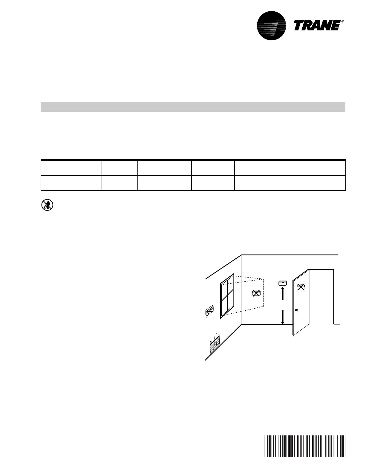
Location
Install the thermostat about 5 ft (1.5m) above the floor in an
area with good air circulation at average temperature. See
Fig. 1. Avoid installing the thermostat where it can be affected
by the following:
• Drafts, or dead spots behind doors and in corners.
• Hot or cold air from ducts.
• Radiant heat from sun or appliances.
• Concealed pipes and chimneys.
• Unheated (uncooled) areas such as an outside wall
behind the thermostat.
Wallplate Installation
Position wallplate horizontally on the wall or on a 2 in. x 4 in.
wiring box.
1. Position and level the wallplate for appearance only (the
thermostat will function properly even when
not level).
Fig. 1. Typical location of thermostat.
® U.S. Registered Trademark
Copyright © American Standard Inc. 1999
69-1213-1
Page 2
XT302C DELUXE PROGRAMMABLE HEAT-COOL THERMOSTAT
THERMOSTAT
WALL
B RW2
Y1 Y2 G
W1
HH
OT OT
WIRES
THROUGH WALL
WALL
ANCHORS
(2)
MOUNTING
HOLES
MOUNTING
SCREWS
M15044
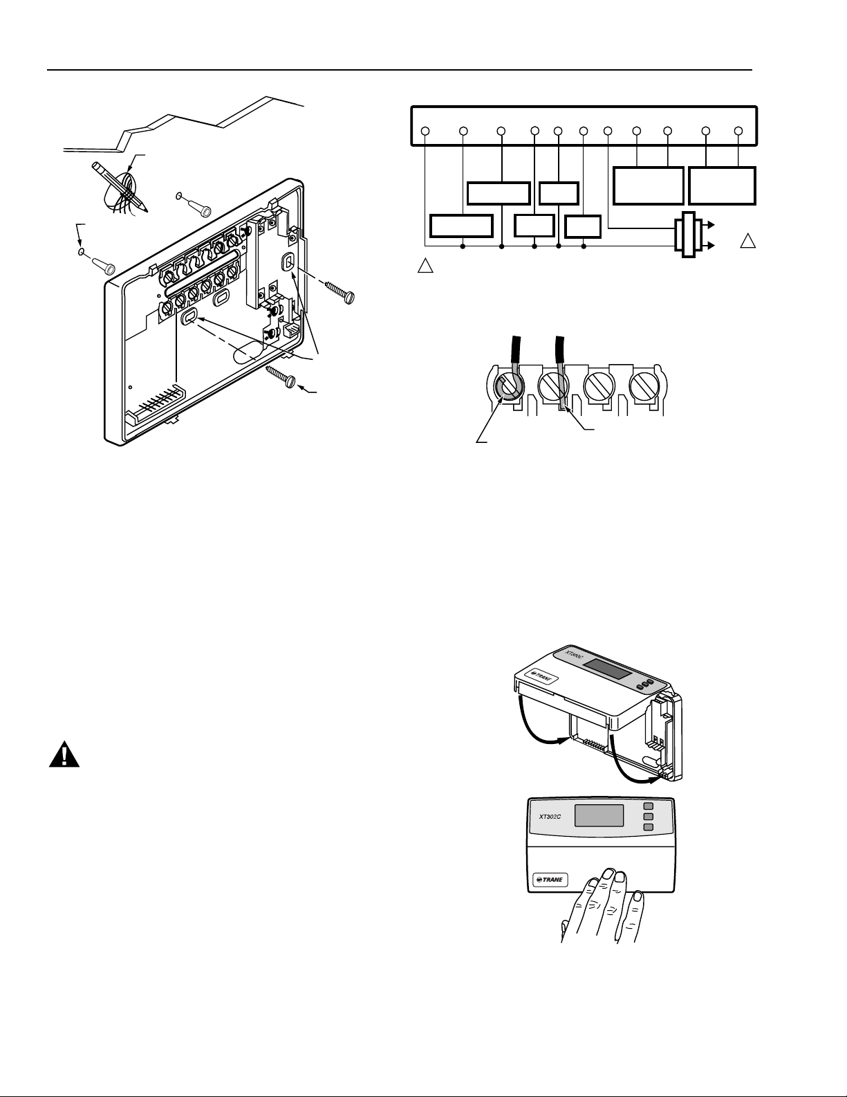
Fig. 2. Mounting the wallplate.
2. Use a pencil to mark the mounting holes. See Fig. 2.
3. Remove the wallplate from the wall and drill two 3/16
inch holes in the wall (if drywall) as marked. For firmer
material such as plaster, drill two 7/32 inch holes.
Gently tap anchors (provided) into the drilled holes until
flush with the wall.
4. Position the wallplate over the holes, pulling wires
through the wiring opening.
5. Loosely insert the mounting screws into the holes.
6. Tighten mounting screws.
BLUE
YELLOW
COMPRESSOR
CONTACTOR 2
COMPRESSOR
CONTACTOR 1
1
POWER SUPPLY. PROVIDE DISCONNECT MEANS
AND OVERLOAD PROTECTION AS REQUIRED.
BROWN
WHITE
HEAT
STAGE 1
BLACK
HEAT
STAGE 2
GREEN
FAN
RED
HUMIDISTAT
OPENS ON RISE
TAYSTAT253A
OUTDOOR
TEMPERATURE
SENSOR
TAYSENS100A
TRANSFORMER
Fig. 3. Typical hookup of XT302C in a heat cool system.
FOR STRAIGHT
FOR WRAPAROUND
INSERTION STRIP
7/16 IN. (11 MM).
INSERTION STRIP
5/16 IN. (8 MM).
M4826
Fig. 4. Proper wiring technique.
Mounting Thermostat
1. Engage tabs at the top of the thermostat and wallplate.
See Fig. 5.
2. Press lower edge of case to close and latch.
NOTE: To remove thermostat from wall, first pull out at
bottom of thermostat; remove top last.
L1
(HOT)
L2
M17116
1
WIRING
All wiring must comply with local electrical codes and
ordinances. Refer to Fig. 3 for typical hookup diagram. A letter
code is located near each terminal for identification.
WARNING
Electronic Shock or Equipment Damage Hazard.
Can shock individuals or cause equipment
damage.
Disconnect power before wiring to prevent electrical
shock or equipment damage.
1. Loosen the terminal screws on the wallplate and
connect the system wires. See Fig. 4.
NOTE: Use 18 gauge, color-coded thermostat cable
for proper wiring.
2. Securely tighten each terminal screw.
3. Push excess wire back into the hole.
4. Plug the hole with nonflammable insulation to
prevent drafts from affecting the thermostat.
Pub. No. 18-HD25D7-5
69-1213—1 (T8624)
A.
ENGAGE TABS
AT TOP OF
THERMOSTAT
AND WALLPLATE.
PRESS LOWER
B.
EDGE OF CASE
TO LATCH.
M17151
Fig. 5. Mounting thermostat on wallplate.
2
Page 3
XT302C DELUXE PROGRAMMABLE HEAT-COOL THERMOSTAT
SET WAKE TIMES
AND SETPOINTS
INCREASE TIME
SETTING OR SCROLL
FORWARD THROUGH
INSTALLER SETUP
AND SYSTEM TEST
SET CURRENT
DAY AND TIME
RETURN TO NORMAL
OPERATIONS
SET CURRENT OR
PROGRAM DAY
ENTER INDEFINITE
OR TIMED HOLD MODE
DECREASE TIME SETTING
OR SCROLL BACKWARD
THROUGH INSTALLER
SETUP AND SYSTEM TEST
CHANGE BETWEEN
DAYLIGHT SAVINGS
AND STANDARD TIME
Run
Program
Hold Temp
COPY ONE
PROGRAMMED DAY
TO ANOTHER DAY
INCREASE TEMPERATURE SETTING OR SCROLL
FORWARD THROUGH INSTALLER SETUP OPTIONS
Set Current
Day/Time
Day
Daylight
Time
Time
Copy
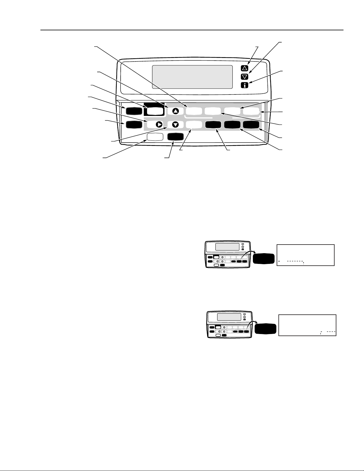
Fig. 6. XT302C key locations and descriptions.
Using Thermostat Keys
The thermostat keys are used to:
• Set current day and time,
• Program times and setpoints for heating and cooling,
• Temporarily override program temperatures,
• Display present setting,
• Configure Installer Setup,
• Check Self-Test,
• Display outdoor temperature (optional accessory),
• Set the system operation, and
• Set the fan operation.
See Fig. 6 for keypad explanation.
SETTINGS
System and Fan Settings
The system default setting is Heat and the fan default setting
is Auto. Use the System and Fan keys to change the settings.
See Figs. 7 and 8. The fan settings can be set for each
program period individually. The system selection is for all the
program periods.
DECREASE
TEMPERATURE
SETTING OR
SCROLL BACKWARD
THROUGH INSTALLER
SETUP OPTIONS
DISPLAY
INFORMATION
SUCH AS PRESENT
SETTINGS
AND OUTDOOR
TEMPERATURE
SET RETURN TIMES
AND SETPOINTS
Leave
Wake
Heat/Cool
Settings
CHANGE BETWEEN
HEATING AND
COOLING SETPOINTS
Set Program
Return Sleep
SystemFilter Fan
SELECT FILTER
EXPIRATION IN
NUMBER OF DAYS
SET SLEEP TIMES
AND SETPOINTS
SET LEAVE TIMES
AND SETPOINTS
SELECT FAN
OPERATION
SELECT SYSTEM
OPERATION (HEAT,
COOL, OFF, AUTO)
M17118
System settings control the thermostat operation as follows:
Heat: The thermostat controls the heating.
Off: Both the heating and cooling are off.
Cool: The thermostat controls the cooling.
Auto: The thermostat automatically changes between
heating and cooling operation, depending on the indoor
temperature.
Set Current
Run
Day/Time
Program
Hold Temp
Leave
Wake
Return Sleep
Set Program
Time
Heat/Cool
Day
Daylight
Time
SystemFilter Fan
Settings
Copy
System
System
Heat
Auto
Off
Cool
Fig.7. System key location and display.
Fan settings control the system fan as follows:
On: Fan operates continuously.
Auto: Fan operates with equipment.
Set Current
Run
Day/Time
Program
Hold Temp
Leave
Wake
Return Sleep
Set Program
Time
Heat/Cool
Day
Daylight
Time
SystemFilter Fan
Settings
Copy
Fan
Fig. 8. Fan key location and display.
M12956
Fan
M12957
Auto
On
NOTE: Always press the keys with your fingertip or similar
blunt tool. Sharp instruments like a pen or pencil
point can damage the keyboard.
Pub. No. 18-HD25D7-5
3
69-1213—1 (T8624)
Page 4
XT302C DELUXE PROGRAMMABLE HEAT-COOL THERMOSTAT
Temperature Settings
Refer to Table 2 for the default program. For 7-Day and
24-Hour Operation, the settings are the same for each day of
the week. Refer to the Owners Guide, Pub. No. 22-5127-04,
for instructions on changing the default settings.
Table 2. Default Program Settings.
Period Time
Setpoint
Wake 6:00 AM 70°F
(21°C)
Leave 8:00 AM 62°F
(16.5°C)
Return 5:00 PM 70°F
(21°C)
Sleep 10:00 PM 62°F
(16.5°C)
The Leave, Return and Sleep periods may be cleared. For
example, the daytime energy-savings period (from Leave to
Return) may not be used by the homeowner. To clear any
period, follow the instructions in the Owners Guide in the
Heat
Clearing Schedule Period
Comfort-R™
CONTROL
Adaptive
Intelligent
Recovery™
CONTROL
(A HONEYWELL
TRADEMARK)
COOLING
DROOP
TEMPERATURE
DISPLAY
CLOCK
FORMAT
SYSTEM
SETTING
(HEATING
AND
COOLING
SETTING)
OUTDOOR
TEMPERATURE
DISPLAY
PROGRAMMING
M17110
OFF ON
ON
ON
FARENHEIT (°F)
24-HOUR
CLOCK FORMAT
AUTO/MANUAL
(SYSTEM
AUTOMATICALLY
SELECTS
HEAT OR COOL;
YOU CAN
SELECT HEAT,
COOL OR OFF.)
NO OUTDOOR
TEMPERATURE
IS DISPLAYED
7-DAY
PROGRAMMING
section.
OFF
(CONVENTIONAL
RECOVERY)
OFF
CENTIGRADE (°C)
24-HOUR
CLOCK FORMAT
MANUAL ONLY
(YOU SELECT
HEAT, COOL
OR OFF.)
NO OUTDOOR
TEMPERATURE
IS DISPLAYED
24-HOUR
PROGRAMMING
Figure 9. Customizing Your Thermostat chart,
from Owners Guide, Pub. No. 22-5127-04.
Cool
Setpoint
78°F
(25.5°C)
85°F
(29.5°C)
78°F
(25.5°C)
82°F
(28°C)
Fan
Setting
Auto
Auto
Auto
Auto
AUTO ONLY
(SYSTEM
AUTOMATICALLY
SELECTS HEAT
OR COOL)
CONSTANT
TEMPERATURE
SETPOINT
PROGRAMMING
INSTALLER SETUP
The Installer Setup is used to customize the thermostat for
specific systems. Some of the options include Comfort-R™
control activation, Fahrenheit vs. Centigrade temperature
display, outdoor temperature display (requires outdoor
sensor installation), and system changeover. Installer Setup
numbers are listed in Table 3. The table includes all the
configuration options and the factory-settings for the
XT302C Deluxe Programmable Multistage Thermostat .
NOTE: For most applications, the thermostat factory-
IMPORTANT
Installer Setup Procedure
settings apply. Review the factory settings in Table 2
and if no changes are necessary, go to the Installer
Self-Test section.
The chart Customizing Your Thermostat found in the
beginning of the Owners Guide (see Fig. 9) must be
completed. The homeowner identifies the options
you install by referring to this chart.
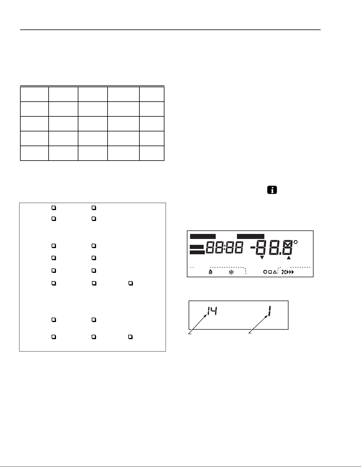
1. Press and hold the Information , Increase ▲,
and Decrease ▼ keys at the same time until all display
segments and the first setup number displays
(all display segments appear for approximately three
seconds before the setup number displays). See
Figs. 11 and 12.
Set Program
Hold for
Em Ht
Start Time
Aux Ht
Mon
TueWedThuFriSatSun
Wake
LeaveReturnSleep
Set Day/Time
AM
PM
In
System Fan
Off Auto
Em
Heat
Cool
Temporary Setting Enrg
Heat
Recovery
DST
Wait
Cool
Auto
Sav
Room
Outdoor
Repl Batt
Auto
On
M17111
Fig. 10. Display of all the segments of the LCD.
INSTALLER SETUP
NUMBER DISPLAY
(COLUMN 2 OF TABLE 3)
FACTORY SETTING OR OTHER
CHOICE DISPLAY (COLUMN 3
OR 5 OF TABLE 3)
M10349
Fig. 11. Display of Installer Setup number and option.
Pub. No. 18-HD25D7-5
69-1213—1 (T8624)
4
Page 5

XT302C DELUXE PROGRAMMABLE HEAT-COOL THERMOSTAT
— To advance to the next Installer Setup, press Time ▲▲.
— To change a setting, press Increase ▲ or Decrease ▼.
— To scroll the Installer Setup numbers backwards, press
Time ▼▼.
— To exit the Installer Setup, press Run Program.
CAUTION
Equipment Damage Hazard.
Can cause permanent equipment damage.
Electric heat systems must be configured to 1 in
Installer Setup number 2 to prevent equipment damage
caused by the system running without the fan.
Table 3. Installer Setup Options for the XT302C.
Press Time
▲ or ▼
Installer
Select
Programming 42
Fan operation 2 0 Conventional
Number of
heating Stages
Stage 1 heating
rate
cycle
Stage 2 heating
rate
cycle
Number of
Cooling Stages
Stage 1 cooling
cycle rate
Stage 2 cooling
cycle rate
System setting
adjustment
Setup Number
Press Time ▼ to
bypass 2–41
and go directly
to setup #42
3 2 2 heating stages 0 or 1 0—no heating
4 3 3—3 cph
5 5 5—5 cph
8 1 1 cooling stage 0 or 2 0—no cooling
9 3 3—3 cph
10 3 3—3 cph
12 0 Auto changeover 1 or 2 1—Manual changeover
Display Description Display Description
0 7-day programming 1 or 2 1—24-hour programming
Press Increase ▲ or Decrease ▼ to change setting
Factory Setting Other Choices
applications where
equipment
fan operation in heat
mode
recommended 5, 6, or
9 cph not
recommended
recommended
3, 6, or 9 cph not
recommended
recommended
2 or 5 cph not
recommended
recommended
2 or 5 cph not
recommended
IMPORTANT
controls
Only configurable numbers displa y.
Example: Installer
Setup Number 1 does not display because it is not
configurable. Review the factory settings in Table 3
and make any desired changes in the Actual Settings
column. When the Installer Setup is complete, review
the settings to confirm that they match the system and
the box es you checked in the Customizing Your
Thermostat chart located in the Owners Guide.
Actual
Setting
2—No programming
1 Applications where
5, 6, or 9 5—5 cph
3, 6, or 9 3—3 cph
2 or 5 2—2 cph
2 or 5 2—2 cph
thermostat
operation in heat mode
1—1 heating stage
6—6 cph
9—9 cph
6—6 cph
9—9 cph
2—2 cooling stages
5—5 cph
5—5 cph
2—Auto changeover only
controls fan
(continued)
Pub. No. 18-HD25D7-5
5
69-1213—1 (T8624)
Page 6

XT302C DELUXE PROGRAMMABLE HEAT-COOL THERMOSTAT
Table 3. Installer Setup Options for the XT302C (continued).
Press Time
Press Increase ▲ or Decrease ▼ to change setting
Factory Setting Other Choices
1 Conventional recovery
Recovery (a
Honeywell trademark)
(system starts recovery at
programmed time)
control is activated
Select
Adaptive
Intelligent
Recovery™
control
▲ or ▼
Installer
Setup Number
Display Description Display Description
13 0 Adaptive Intelligent
(system starts early so
setpoint is reached by
start of program
period)
Degree
temperature
14 0 Temperature displays
in °F
1 Temperature displays in °C
display
Clock format 16 0 12-hour clock format 1 24-hour clock format
Extended fan
operation in
a
heating
19 0 No extended fan
operation after the call
for heat ends
1, 2 or 3 1—Fan operation extends
30 seconds after the call
ends.
2—Fan operation extends
60 seconds after the call
ends.
3 —Fan operation extends
90 seconds after the call
ends.
Extended fan
operation in
cooling
20 0 No extended fan
operation after the
call for cool ends
1, 2 or 3 1—Fan operation extends
30 seconds after the call
ends.
2—Fan operation extends
60 seconds after the call
ends.
3 —Fan operation extends
90 seconds after the call
ends.
Outdoor
temperature
display (select
models)
Comfort-R
Enable
Minimum
Deadband
Between
Heating and
Cooling in Auto
Changeover
Mode
24 0 No outdoor
temperature displays
1 Outdoor temperature
displays. Requires a
TAYSENS100A Outdoor
Sensor.
28 0 No fan delay 1 or 2 1—30 seconds
2—15 seconds
30 4 Heating and cooling
setpoints can be set
no closer than 4°F
(2°C)
3 thru 10 Heating and cooling
setpoints can be set no
closer than the chosen
value:
3—3°F (1.5°C)
4—4°F (2°C)
5—5°F (2.5°C)
6—6°F (3°C)
7—7°F (3.5°C)
8—8°F (4°C)
9—9°F (4.5°C)
10—10°F (5°C)
Minimum On
Time (Heat)
32 5 5-minute minimum on
time for compressor
0 thru 15 Minimum number of minutes
(0 thru 15) the compressor
will be on during call for
heat
Actual
Setting
Pub. No. 18-HD25D7-5
69-1213—1 (T8624)
(continued)
6
Page 7

XT302C DELUXE PROGRAMMABLE HEAT-COOL THERMOSTAT
Table 3. Installer Setup Options for the XT302C (continued).
Press Time
▲ or ▼
Installer
Select
Minimum On
Setup Number
Display Description Display Description
33 10 10-minute minimum on
Time (Cool)
Temperature
34 85 Highest setpoint
range stops in
heating
Temperature
35 65 Lowest setpoint
range stops in
cooling
Temperature
37 0 No difference
display
adjustment
Minimum Off
38 5 5 minute minimum off
Time (Heat)
Minimum Off
39 5 5 minute minimum off
Time (Cool)
Cooling Droop 41 1 Cooling droop
Programming 42
0 7-day programming 1 or 2 1—24-hour programming
Press Time ▼ to
bypass 2–41
and go directly
to setup #42
Press Increase ▲ or Decrease ▼ to change setting
Factory Setting Other Choices
time for compressor
heating can be set to
cooling can be set to
in displayed
temperature and
actual room
temperature
time for the
compressor
time for the
compressor
activated
0 thru 15 Minimum number of minutes
(0 thru 15) the compressor
will be on during call for
cool
55 to 85 Temperature range (1°F
increments) heating
setpoint can be set to
65 to 99 Temperature range (1°F
increments) cooling
setpoint can be set to
3, 2, 1, -1,
-2, or
-3
3—Display adjusts to 3°F
higher than actual room
temperature
2—Display adjusts to 2°F
higher than actual room
temperature
1—Display adjusts to 1°F
higher than actual room
temperature
-1—Display adjusts to 1°F
lower than actual room
temperature
-2—Display adjusts to 2°F
lower than actual room
temperature
-3—Display adjusts to 3°F
lower than actual room
temperature
0 thru 15 Minimum number of minutes
(0 thru 15) the compressor
will be off between calls for
heat
0 thru 15 Minimum number of minutes
(0 thru 15) the compressor
will be off between calls for
cool
0 No cooling droop
2—No programming
Actual
Setting
IMPORTANT
Review the settings to confirm that they match the
system. Press Run Program to exit the Installer
Setup. The thermostat saves the Installer Setup
changes and initiates a reset in order to operate
using the new settings.
NOTE: For initial installations only, set the current day and
time following the setup reset.
Setting Current Day and Time
1. Press Set Current Day/Time.
Set Day/Time
Set Current
Day/Time
Run
Day/Time
Program
Hold Temp
Leave
Wake
Set Program
Time
Heat/Cool
Day
Settings
Daylight
Copy
Time
Return Sleep
SystemFilter Fan
Mon
Set Current
NOTE: On initial power up or after an extended power loss,
1:00 pm flashes on the display until a key is pressed.
7
PM
Pub. No. 18-HD25D7-5
69-1213—1 (T8624)
M12951
Page 8

XT302C DELUXE PROGRAMMABLE HEAT-COOL THERMOSTAT
2. Press Day until the current day displays.
Set Day/Time
Day
Set Current
Run
Program
Hold Temp
Leave
Wake
Day/Time
Day
Daylight
Time
Return Sleep
Set Program
Time
Heat/Cool
SystemFilter Fan
Settings
Copy
Tue
PM
M12952
NOTE: Sun=Sunday, Mon=Monday, Tue=Tuesday,
Wed=W ednesday, Thu=Thursday, Fri=Friday,
Sat=Saturday.
3. Press Time ▲ or Time ▼ until the current time displays.
Time
Set Current
Run
Day/Time
Program
Hold Temp
Day
Daylight
Leave
Wake
Return Sleep
Set Program
Time
Heat/Cool
SystemFilter Fan
Settings
Copy
Time
Set Day/Time
Tue
AM
M12953
NOTE: Tapping the Set Current Day/Time will change the
time in one hour increments.
NOTE: If the current time is Daylight Savings Time, press
Daylight Time until DST displays.
Set Day/Time
AM
DST
M12954
Daylight
Time
Set Current
Run
Day/Time
Program
Hold Temp
Day
Leave
Wake
Return Sleep
Set Program
Time
Heat/Cool
SystemFilter Fan
Settings
Daylight
Copy
Time
Tue
4. Press Run Program.
To start the self-test:
Press and hold the Increase ▲ and Decrease ▼ keys at the
same time until all display segments and the number 10
appears (all displays segments appear for approximately
three seconds before the test number displays). See
Figs. 12 and 13.
Table 4. Tests Available In The Installer Self-Test.
Test
Number Self-Test Description
10 Heating Equipment
30 Cooling Equipment
40 Fan Equipment
50 Comfort-R Terminals (H-H)
60 Keyboard Operation
70 Device Information
Set Program
Hold for
Em Ht
Start Time
Aux Ht
Mon
TueWedThuFriSatSun
Wake
LeaveReturnSleep
System Fan
Em
Heat
Off Auto
Set Day/Time
AM
PM
In
Cool
Temporary Setting Enrg
Heat
Recovery
DST
Wait
Cool
Auto
Sav
Room
Outdoor
Repl Batt
Auto
On
M17111
Fig. 12. Display of all the segments of the LCD.
Run
Program
Set Current
Run
Day/Time
Program
Hold Temp
Leave
Wake
Return Sleep
Set Program
Time
Heat/Cool
Day
Daylight
Time
SystemFilter Fan
Settings
Copy
Tue
Wake
System Fan
Heat
AM
Room
DST
Auto
M12955
INSTALLER SELF-TEST
Use the Installer Self-Test to check the thermostat operation.
Refer to Table 4 for a list of the available self-tests.
CAUTION
Equipment Damage Hazard.
Equipment damage can occur if the compressor
is cycled too quickly.
The minimum off time is deactivated during the
Installer Self-T est.
Perform the test so that the compressor is cycled
slowly.
TEST NUMBER
M10257A
Fig. 13. Display of test number.
Refer to Table 5 for the directions and results of the specific tests.
NOTE: Press Time ▲▲ to advance to the next test and Time ▼▼
to go back to the previous test. Press Run Program to
exit the self-test. This mode times out 5 minutes after
the last key press.
NOTE: Press Time ▼▼ to return to the previous test or Time ▲▲
to advance to the next test.
NOTE: To exit, press Time ▲▲ or Time ▼ ▼ then Run Program.
Pub. No. 18-HD25D7-5
69-1213—1 (T8624)
8
Page 9

XT302C DELUXE PROGRAMMABLE HEAT-COOL THERMOSTAT
Table 5. Installer Self-Test Options.
Key to
Press
Test
Number Description
Heating Equipment Self-Test (10)
Time ▲ 10 Enter heating equipment self-test.
Temp ▲ 11 First stage heat turns on. When Installer Setup number 2 is 1, the system fan is also energized.
Temp ▲ 12 Second stage heat turns on.
Temp ▼ 11 Second stage heat turns off.
Temp ▼ 10 First stage heat turns off.
Cooling Equipment Self-Test (30)
Time ▲ 30 Enter cooling equipment self-test.
Temp ▲ 31 First stage cool and fan turn on.
Temp ▲ 32 Second stage cool turns on.
Temp ▲ 31 Second stage cool turns off.
Temp ▼ 30 First stage cool and fan turn off.
Fan Equipment Self-Test (40)
Time ▲ 40 Enter fan equipment self-test.
Temp ▲ 41 Fan turns on.
Temp ▼ 40 Fan turns off.
Comfort-R Terminals Self-Test (50)
Temp ▲ 50 Enter Comfort-R self-test.
Temp ▼ 51 Reads HH terminals. If the terminals are open and Comfort-R is enabled, display reads
% humidity. If the terminals are closed no % humidity displays.
Keyboard Operation Self-Test (60)
Time ▲ 60 7 Enter keyboard operation self-test.
Temp ▲ 60 9 Increase test number displays.
Temp ▼ 60 8 Decrease test number displays.
Day 60 11 Day test number displays.
Copy 60 12 Copy test number displays.
System 60 3 System test number displays.
Fan 60 10 Fan test number displays.
Set
60 1 Set Current Day/Time test number displays.
Current
Day/Time
Run
60 15 Run Program test number displays.
Program
Daylight
60 19 Daylight Time test number displays.
Time
Heat/ Cool
60 5 Heat/Cool Settings test number displays.
Settings
Wake 60 0 Wake test number displays.
Leave 60 14 Leave test number displays.
Return 60 16 Return test number displays.
Sleep 60 2 Sleep test number displays.
Filter 60 17 Filter test number displays.
i 60 13 Information test number displays.
Device Information Self-Test (70) - Refer to following section.
Pub. No. 18-HD25D7-5
9
69-1213—1 (T8624)
Page 10

XT302C DELUXE PROGRAMMABLE HEAT-COOL THERMOSTAT
DEVICE INFORMATION
SELF-TEST (70)
1. Press Temp ▲ and ▼ keys simultaneously, then press
Time ▼ ▼ to access the thermostat information.
M4934
2. Press Increase ▲ to display the production date code
in a 3-digit format. The first two digits represent the
month and the third digit represents the last digit of the
year (Example: 128=December 1998).
M17112
3. Press Increase ▲ again to display the software
identification code.
(Example: 200 = software ID code 200)
4. Press Increase ▲ again to display the software revision
number (Example: 001=Revision number 1).
M10229
5. Press the Increase ▲ again to display the model
identification number. (Example: 314 = Model ID 314)
M4933A
6. Press Run Program to exit the self-test. The self-test
mode times out 5 minutes after the last key press.
CHECKOUT
Outdoor Temperature Sensor
(optional accessory)
Expose the outdoor temperature to outdoor air for a minimum
of five minutes before reading.
M17113
TROUBLESHOOTING GUIDE
Symptom Possible Cause Action
Display will not come
on.
Temperature display is
incorrect.
Temperature
displaying digits as
dashes (---).
Temperature settings
will not change.
(Example:
Cannot set the
heating higher or the
cooling lower.)
Thermostat is not being
powered.
Room temperature
display has been
reconfigured.
Thermostat is configured
for °F or °C display.
Bad thermostat location. Relocate the thermostat.
Internal temperature
measurement failure.
The upper or lower
temperature limits were
reached.
The setpoint temperature
range stops were
configured.
Check for 24 Vac between R and W terminals.
Check if the circuit breaker is tripped—reset the circuit breaker.
Check if the system fuse is blown—replace the fuse.
Check if the power switch on the HVAC equipment is in the
Off position—set to the On position.
Check wiring between thermostat and HVAC equipment—replace any
broken wires and tighten any loose connections.
If 24 Vac is present, proceed with troubleshooting.
Enter Installer Setup number 37 and reconfigure the display.
Enter Installer Setup number 14 and reconfigure the display.
Contact distributor or retailer.
Check the temperature setpoints:
Heating limits are 55 to 85°F (13 to 29°C).
Cooling limits are 65 to 99°F (18 to 37°C).
Check Installer Setup numbers 34 and 35 and reconfigure the
setpoint stops.
(
continued
)
Pub. No. 18-HD25D7-5
69-1213—1 (T8624)
10
Page 11

XT302C DELUXE PROGRAMMABLE HEAT-COOL THERMOSTAT
TROUBLESHOOTING (Continued).
Symptom Possible Cause Action
Heating will not come
on.
Heating will not come
on.
Cooling will not come
on.
Heating or cooling
come on momentarily
and shut off
System on indicator
(flame=heat,
snowflake=cool)
displays, but no
warm or cool air is
coming from the
registers.
Outdoor temperature
not displayed
or is incorrect.
System on indicator
reads Filter and
backlight is flashing.
Time displaying digits
as three E’s (EEE).
No power to the
thermostat.
Thermostat minimum off
time is activated.
System selection is not
set to Heat.
Heating setpoint is below
room temperature.
No power to the
thermostat.
Thermostat minimum off
time is activated.
System selection is not
set to Cool.
Cool setpoint is above
room temperature.
Heat or cool circuit is
opening up or becoming
high impedance.
Heating equipment turns
on the fan when the
furnace has warmed up
to a setpoint.
Heating or cooling
equipment is not
operating.
Option not activated. Enter Installer Setup number 24 and set to 1. Thermostat must have OT
Outdoor sensor is
connected incorrectly.
Wrong sensor. Replace sensor with TAYSENS100A sensor.
Filter expired. Refer to the
Filter expired. Refer to the
Internal memory failure. Contact distributor or retailer.
Check for 24 Vac between R and W terminals.
If missing 24 Vac:
Check if the circuit breaker is tripped—reset the circuit breaker.
Check if the system fuse is blown—replace the fuse.
Check if the power switch on the HVAC equipment is in the Off
position—set to the On position.
Check wiring between thermostat and HVAC
equipment—replace any broken wires and tighten any loose
connections.
If 24 Vac is present, proceed with troubleshooting.
Wait up to five minutes for the system to respond.
Set system selection to Heat.
Check heating setpoint. Set heating setpoint to desired temperature.
Check for 24 Vac between R and W terminals.
If missing 24 Vac:
Check if the circuit breaker is tripped—reset the circuit breaker.
Check if the system fuse is blown—replace the fuse.
Check if the power switch on the HVAC equipment is in the
Off position—set to the On position.
Check wiring between thermostat and HVAC equipment—replace any
broken wires and tighten any loose connections.
If 24 Vac is present, proceed with troubleshooting.
Wait up to five minutes for the system to respond. Enter Installer Setup
number 39. Reconfigure minimum off time (if required).
Set system selection to Cool.
Check cooling setpoint. Set cooling setpoint to desired temperature.
Add resistor in parallel with load or install interface relay.
Wait a minute after seeing the on indicator and then check the registers.
Verify operation of heating or cooling equipment in self-test.
terminals and a TAYSENS100A installed.
Refer to TAYSENS100A installation instructions and check wiring
between the thermostat and sensor.
Filter Indication
No. 22-5127-04
Filter Indication
section in the Owner’s Guide, Pub.
section.
11
Pub. No. 18-HD25D7-5
69-1213—1 (T8624)
Page 12

XT302C DELUXE PROGRAMMABLE HEAT-COOL THERMOSTAT
Pub. No. 18-HD25D7-5
69-1213—1 T. C. Rev. 1-99
69-1213—1 (T8624)
Printed in Taiwan R.O.C.
12
American Standard Inc.
Troup Highway
Tyler, TX 75711-9010
 Loading...