

Trane X1351153001, X1351152701, X1379084501, X1379085101, X1379084801 Installation, Operation And Maintenance Manual
...
Installation, Operation, and
Maintenance
Wired Temperature Sensors
December 2008
BAS-SVX10C-EN

Copyright
© 2008 Trane All rights reserved
This document and the information in it are the property of Trane and may not be used
or reproduced in whole or in part, without the written permission of Trane. Trane reserves
the right to revise this publication at any time and to make changes to its content without
obligation to notify any person of such revision or change.
Trademarks
Trane and its logo are trademarks of Trane in the United States and other countries. All
trademarks referenced in this document are the trademarks of their respective owners.
Warnings, Cautions, and Notices
Warnings, cautions, and notices are provided in appropriate places throughout this
document:
WARNING: Indicates a potentially hazardous situation which, if not avoided,
could result in death or serious injury.
CAUTION: Indicates a potentially hazardous situation which, if not avoided,
may result in minor or moderate injury. It may also be used to alert against
unsafe practices.
NOTICE: Indicates a situation that may result in equipment or property-damage-
only accidents.

Table of Contents
General Information . . . . . . . . . . . . . . . . . . . . . . . . . . . . . . . . . . . . . . . . . . . . . . . . . . . . 5
Product Description . . . . . . . . . . . . . . . . . . . . . . . . . . . . . . . . . . . . . . . . . . . . . . . . 5
Part Numbers . . . . . . . . . . . . . . . . . . . . . . . . . . . . . . . . . . . . . . . . . . . . . . . . . . . . . 6
Dimensions . . . . . . . . . . . . . . . . . . . . . . . . . . . . . . . . . . . . . . . . . . . . . . . . . . . . . . . 7
Pre-Installation . . . . . . . . . . . . . . . . . . . . . . . . . . . . . . . . . . . . . . . . . . . . . . . . . . . . . . . . . 8
Location Considerations . . . . . . . . . . . . . . . . . . . . . . . . . . . . . . . . . . . . . . . . . . . . 8
Height Requirements . . . . . . . . . . . . . . . . . . . . . . . . . . . . . . . . . . . . . . . . . . . . . . . 8
Mounting Surfaces . . . . . . . . . . . . . . . . . . . . . . . . . . . . . . . . . . . . . . . . . . . . . . . . . 8
Installation and Configuration: Display Sensor . . . . . . . . . . . . . . . . . . . . . . . . . . . . 9
Mounting the Back Plate . . . . . . . . . . . . . . . . . . . . . . . . . . . . . . . . . . . . . . . . . . . . 9
Wiring the Sensor . . . . . . . . . . . . . . . . . . . . . . . . . . . . . . . . . . . . . . . . . . . . . . . . . 10
Configuring the Display Sensor . . . . . . . . . . . . . . . . . . . . . . . . . . . . . . . . . . . . . 11
Replacing the Cover . . . . . . . . . . . . . . . . . . . . . . . . . . . . . . . . . . . . . . . . . . . . . . . 16
Configuration Procedure . . . . . . . . . . . . . . . . . . . . . . . . . . . . . . . . . . . . . . . 11
Optional Configuration Features . . . . . . . . . . . . . . . . . . . . . . . . . . . . . . . . 15
Installation: All Models Other Than the Display Sensor . . . . . . . . . . . . . . . . . . . 17
Mounting the Back Plate . . . . . . . . . . . . . . . . . . . . . . . . . . . . . . . . . . . . . . . . . . . 17
Installing the COMM Module (optional) . . . . . . . . . . . . . . . . . . . . . . . . . . . . . . 20
Changing the Setpoint Thumb Wheel (optional) . . . . . . . . . . . . . . . . . . . . . . 21
Wiring the Sensor . . . . . . . . . . . . . . . . . . . . . . . . . . . . . . . . . . . . . . . . . . . . . . . . . 21
Replacing the Cover . . . . . . . . . . . . . . . . . . . . . . . . . . . . . . . . . . . . . . . . . . . . . . . 22
Operation . . . . . . . . . . . . . . . . . . . . . . . . . . . . . . . . . . . . . . . . . . . . . . . . . . . . . . . . . . . . . 23
Changing Temperature Settings . . . . . . . . . . . . . . . . . . . . . . . . . . . . . . . . . . . . 23
Changing System Settings . . . . . . . . . . . . . . . . . . . . . . . . . . . . . . . . . . . . . . . . . 23
Changing Fan Settings . . . . . . . . . . . . . . . . . . . . . . . . . . . . . . . . . . . . . . . . . . . . . 23
Selecting Temporary Occupancy (Timed Override) . . . . . . . . . . . . . . . . . . . . 24
Service Pin Request . . . . . . . . . . . . . . . . . . . . . . . . . . . . . . . . . . . . . . . . . . . . . . . 25
Sensors with Occupied/Unoccupied Buttons . . . . . . . . . . . . . . . . . . . . . . 25
Display Sensor . . . . . . . . . . . . . . . . . . . . . . . . . . . . . . . . . . . . . . . . . . . . . . . 25
Star(*)/Double Star(**) Function . . . . . . . . . . . . . . . . . . . . . . . . . . . . . . . . . . . . 26
Sensors with Thumb Wheels . . . . . . . . . . . . . . . . . . . . . . . . . . . . . . . . . . . 26
Display Sensor . . . . . . . . . . . . . . . . . . . . . . . . . . . . . . . . . . . . . . . . . . . . . . . 26
Display Sensor Operation . . . . . . . . . . . . . . . . . . . . . . . . . . . . . . . . . . . . . . . . . . 27
Changing Temperature Settings . . . . . . . . . . . . . . . . . . . . . . . . . . . . . . . . 27
Changing Heating and Cooling Temperature Settings (dual setpoint sys-
tems only) . . . . . . . . . . . . . . . . . . . . . . . . . . . . . . . . . . . . . . . . . . . . . . . . . . 27
Changing System Settings . . . . . . . . . . . . . . . . . . . . . . . . . . . . . . . . . . . . . 28
Changing Fan Settings . . . . . . . . . . . . . . . . . . . . . . . . . . . . . . . . . . . . . . . . 28
BAS-SVX10C-EN 3

Requesting Temporary Occupancy . . . . . . . . . . . . . . . . . . . . . . . . . . . . . . 28
Error codes . . . . . . . . . . . . . . . . . . . . . . . . . . . . . . . . . . . . . . . . . . . . . . . . . . 28
Lock Symbol . . . . . . . . . . . . . . . . . . . . . . . . . . . . . . . . . . . . . . . . . . . . . . . . 28
Maintenance and Troubleshooting . . . . . . . . . . . . . . . . . . . . . . . . . . . . . . . . . . . . . . 29
LEDs . . . . . . . . . . . . . . . . . . . . . . . . . . . . . . . . . . . . . . . . . . . . . . . . . . . . . . . . . . . . 29
Error Codes (Display Sensor) . . . . . . . . . . . . . . . . . . . . . . . . . . . . . . . . . . . . . . . 29
Display Sensor: Output Values—Failure and Default Modes of Operation 29
Measuring Output Resistance . . . . . . . . . . . . . . . . . . . . . . . . . . . . . . . . . . . . . . 30
Display Sensors . . . . . . . . . . . . . . . . . . . . . . . . . . . . . . . . . . . . . . . . . . . . . . 30
All Models Other Than the Display Sensor . . . . . . . . . . . . . . . . . . . . . . . . 30
Cleaning the Sensor . . . . . . . . . . . . . . . . . . . . . . . . . . . . . . . . . . . . . . . . . . . . . . . 32
Replacing the Thumb Wheel . . . . . . . . . . . . . . . . . . . . . . . . . . . . . . . . . . . . . . . 32
Wiring Diagrams . . . . . . . . . . . . . . . . . . . . . . . . . . . . . . . . . . . . . . . . . . . . . . . . . . . . . . 33
Temperature sensors with fan control . . . . . . . . . . . . . . . . . . . . . . . . . . . . . . . 34
Temperature sensors with fan and system control . . . . . . . . . . . . . . . . . . . . 37
Optional COMM module . . . . . . . . . . . . . . . . . . . . . . . . . . . . . . . . . . . . . . . . . . . 40
Specifications and Agency Compliance . . . . . . . . . . . . . . . . . . . . . . . . . . . . . . . . . 41
Specifications . . . . . . . . . . . . . . . . . . . . . . . . . . . . . . . . . . . . . . . . . . . . . . . . . . . . 41
Agency Compliance . . . . . . . . . . . . . . . . . . . . . . . . . . . . . . . . . . . . . . . . . . . . . . . 41
Declaration of CE Conformity . . . . . . . . . . . . . . . . . . . . . . . . . . . . . . . . . . . . . . . 42
4

General Information
This section provides a description of the wired temperature sensors, as well as part numbers and
dimensions.
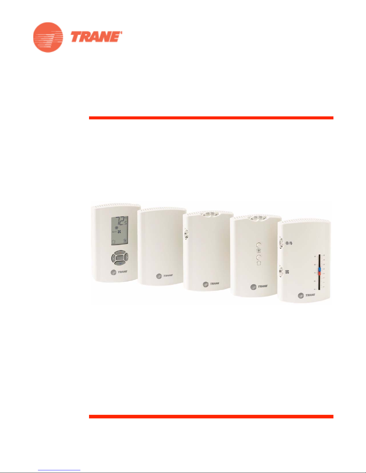
Product Description
Note: The information in this manual applies to both factory and field installed versions of Trane
wired temperature sensors.
®
Tra ne
wired temperature sensors are compatible with any Trane unit controller that uses a
standard 10 kW temperature input. Temperature monitoring is standard on all models. Additional
features are available on some models:
• Fan control
•System control
• Dual or single temperature setpoint control
• Occupancy (timed override) request function
• COMM module—Optional accessory that provides an RJ22 connection for a Trane service tool
for system communication. Must be ordered separately.
• Hot/cold setpoint thumb wheel—Optional accessory allows selecting a temperature setpoint by
color (red/blue for hot/cold) on thumbwheel, rather than by a number. Must be ordered
separately.
The display sensor (p/n X13790886) has an LCD display and includes an RJ11 (RJ22 compatible)
connection for a Trane service tool for system communication. The following features on this
sensor are configurable:
• Temperature units: Fahrenheit (ºF) or Celsius (ºC)
• Temperature resolution: 1.0, 0.5, or 0.1 degrees
• Ability to display setpoint only (zone temperature does not display)
• Single, dual, or no setpoint
• System settings: auto, off, cool, heat, emergency heat
• Deadband (heat/cool setpoint offset for dual setpoint systems)
• Fan settings: high, medium, low, auto, off
• Occupancy (timed override request) function
• Lockable settings to protect against unauthorized use
• Service pin request
BAS-SVX10C-EN 5
General Information
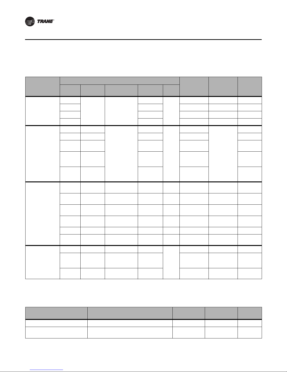
Part Numbers
The following table lists part numbers for each sensor type.
Features
Sensor type
Single
Temperature
sensors
Temperature
sensors with fan
control
Temperature
sensors with fan
and system control
Temperature
sensor with LCD
(1)(2)
display
(1)These sensors can be field configured to match the appli cable unit controller options.
(2)Unit controller inputs for system status, fan status, and service required are not available on this sensor. If replacing a BAYSENS031A or a BA YSENS035A
sensor, and status indicators are required, replace with non-display sensor BAYSENS109A or BAYSENS110A.
No No X1351152801 BAYSENS077A SEN01448
Single No X1351152901 BAYSENS075A SEN01449
No Yes X1351153001 BAYSENS073A SEN01450
Single Off/Auto
Single Off/Run Yes X1379085101 SEN01527
Single
Single
Single
Dual Auto/High
Single Auto/High
Dual Auto/High
Dual Auto/High
Single Auto/High Cool/Off/Heat No No X1379083901 BAYSENS106A SEN01515
Single Low/High
Single No No Yes
Single
Dual
control System Occupancy LEDs
Yes
No No
Yes
Off/Auto/
Low/High
Off/Auto/
Low/Med/
High
Off/Auto/
Low/Med/
High
Off/On/
Auto/Low/
Med/High
Auto/On Cool/Off/Auto/
No
Cool/Off/Auto/
Heat/Em Heat
Cool/Off/Heat/
Em Heat
Cool/Off/Auto/
Heat
Cool/Off/Auto/
Heat
Cool/Off/Heat/
Fan
No
Heat/Em Heat
Yes X1379084801 SEN01524
No X1379084101 SEN01517
Yes X1379084201 SEN01518
No Yes (4) X1379084701 BAYSENS109A SEN01523
No Yes (1) X1379085201 BAYSENS107A SEN01528
No No X1379083701 BAYSENS108A SEN01513
No Yes (4) X1379084601 BAYSENS110A SEN01522
No No X1379085001 NA SEN01526
No X1379088604 NA NA
No X1379088605 BAYSENS135A NA
Part number BAYSENS
X1351152701 BAYSENS074A SEN01447
No
X1379084501
No
X1379088601 NA SEN01599
No
NA
Fan
Global
partsSetpoint
SEN01521
The following table lists part numbers for optional accessories.
Accessory Available for . . . Part number BAYSENS
COMM module (box of 12) All sensors other than the display sensor X1365146702 BAYCOMM005A CON01313
Setpoint thumb wheel: Hot/cold
(box of 12)
6 BAS-SVX10C-EN
Sensors with thumb wheels X1316105702 NA KNB00182
Global
parts
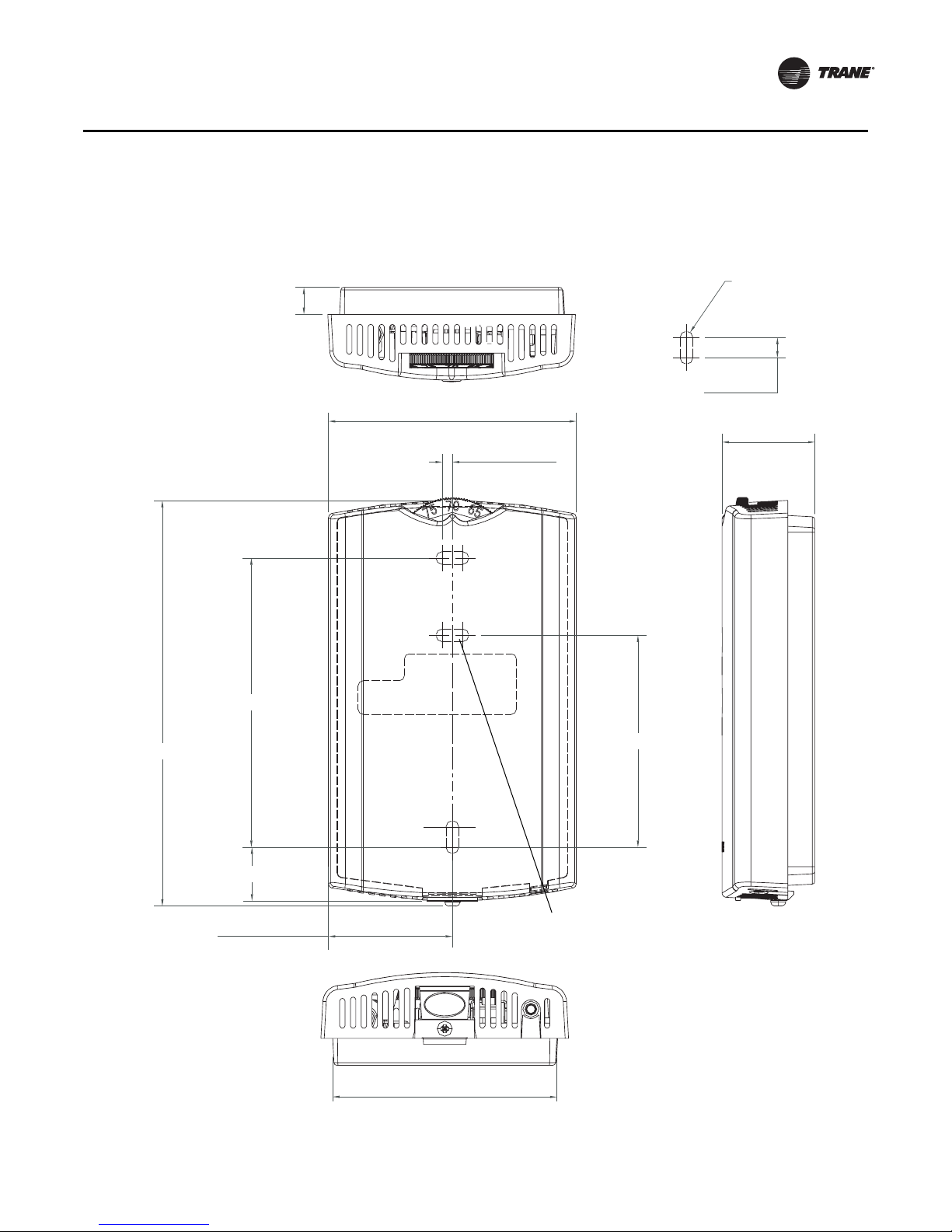
Dimensions
2.9 in (73.5 cm)
1.08 in (27.5 mm)
4.68 in (118.9 mm)
1.45 in (36.8 mm)
0.63 in (15.9 mm)
0.31 in (8 mm)
0.12 in (3 mm)
TYP R.07 in
(R1.9) mm)
3.39 in (86 mm)
2.48 in (63 mm)
2.62 in (66.5 mm)
TYP 0.24 in (6 mm)
Note: There is no center
mounting hole on the
display sensor.
General Information
The following illustration provides specific dimension details. The dimensions are the same for all
models.
BAS-SVX10C-EN 7

Pre-Installation
This section provides the following pre-installation information:
• Location considerations
• Height requirements
• Mounting surfaces
Location Considerations
Placement of the sensor is critical to proper operation. When selecting a location, avoid the
following:
• Areas of direct sunlight
• Areas in the direct airstream of air diffusers
• Exterior walls and other walls that have a temperature differential between the two sides
• Areas that are close to heat sources such as sunlight, appliances, concealed pipes, chimneys,
or other heat-generating equipment
• Drafty areas
• Dead spots behind doors, projection screens, or corners
• Walls that are subject to high vibration
• Areas with high humidity
• High traffic areas (to reduce accidental damage or tampering)
Height Requirements
The recommended maximum mounting height is 54 inches from the bottom of the back plate to
the floor. If a parallel approach by a person in a wheelchair is required, reduce the maximum height
to 48 inches.
Note: Consult section 4.27.3 of the 2002 ADA (Americans with Disability Act) guideline, and local
building codes, for further details regarding wheelchair requirements.
Mounting Surfaces
Using the hardware provided, mount the back plate to a flat surface such as sheetrock or plaster,
or an electrical junction box. The sensor must be mounted plumb for accurate temperature control
and to ensure proper air movement through the sensor.
• If mounting onto sheetrock or plaster, use the plastic threaded anchors (pre-drilling holes is not
usually necessary) and the two M3.5 x 20 mm mounting screws.
• For mounting onto an electrical junction box, use the two 6-32 x 3/4 in. screws.
8 BAS-SVX10C-EN
Security screw
Installation and Configuration: Display Sensor
This section provides step-by-step installation instructions for the display sensor (see applicable
part numbers for the temperature sensor with LCD display on p. p. 6). For installation of all other
sensor models, see p. 17.
Read through the pre-installation information(p. 8) before proceeding with the installation.
Note: Before installing a wired sensor, ensure that a wire access hole is available at the sensor
location and the wire is accessible through the hole. The technician should assume that the
wires are attached to the appropriate unit controller, that there is continuity between the
sensor location and the controller, and that the wires are accurately labeled or identified by
color.
Mounting the Back Plate
WARNI NG
Hazardous voltage!
Disconnect all electric power, including remote disconnects before servicing. Follow proper
lockout/tagout procedures to ensure the power cannot be inadvertently energized. Failure to
disconnect power before servicing could result in death or serious injury.
NOTICE
Equipment damage!
Applying excessive voltage to the sensor will permanently damage it.
Note: Refer to the illustration below when installing the sensor.
1. Shut off power to the unit controller.
2. Remove the cover by firmly pressing the thumb tab at the bottom of the cover and pulling the
cover away from the back plate.
Note: If present, remove the security screw before removing the cover.
3. Feed the wires through the opening in the back plate.
4. Hold the back plate against the mounting surface and mark the screw locations.
5. Secure the back plate to the mounting surface using the included hardware.
BAS-SVX10C-EN 9
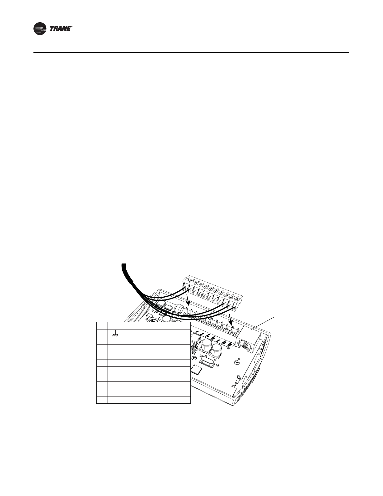
11 24 VAC/VDC
10 (GROUND)
9
8
7COMM–
6COMM+
5 HEAT SETPOINT (HSP)
4 SYS/FAN MODE (MODE)
3 SETPOINT
2 SIGNAL COMMON (COMMON)
1 ZONE TEMPERATURE (ZONE TEMP)
RJ11 (RJ22 compatible)
connection for a Trane
service tool
Installation and Configuration: Display Sensor
Wiring the Sensor
WARNI NG
Hazardous voltage!
Disconnect all electric power, including remote disconnects before servicing. Follow proper
lockout/tagout procedures to ensure the power cannot be inadvertently energized. Failure to
disconnect power before servicing could result in death or serious injury.
NOTICE
Equipment damage!
Applying excessive voltage to the sensor will permanently damage it.
To wire the sensor to the unit controller:
1. Ensure that the wires are connected to the appropriate terminals at the unit controller.
2. Insert each wire into the appropriate location in the terminal block (see the table in Figure 1).
Tighten the terminal screw.
Note: The wire connections can be made while the terminal block is either on the circuit board,
or removed from it.
3. Perform a pull test to ensure that the wires are properly connected.
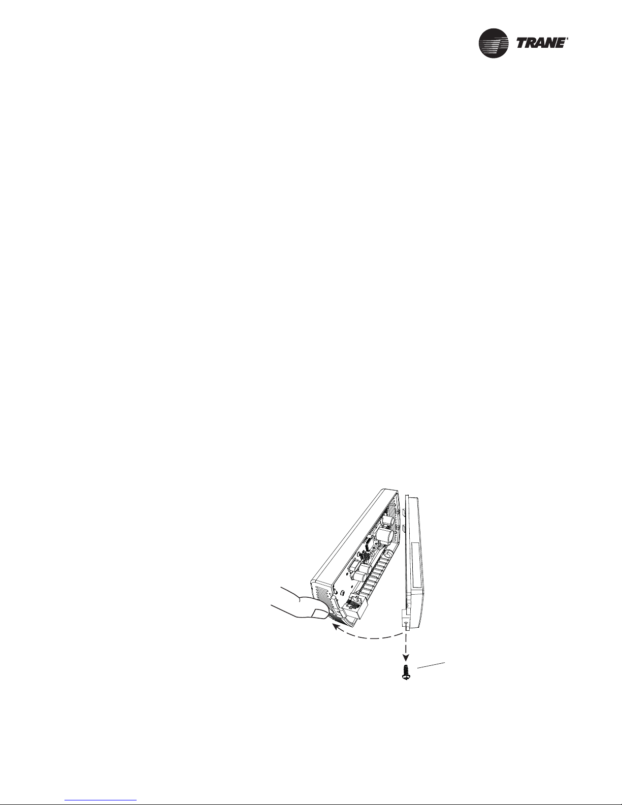
4. If the terminal block was removed from the circuit board, attach it to the pins inside the sensor
cover (Figure 1).
Figure 1. Attaching the terminal block to the pins on the circuit board
10 BAS-SVX10C-EN
5. Push the excess wire into the wall cavity and plug it with nonflammable insulation to prevent
drafts from affecting the sensor.
Important: Do not coil excess wire inside the back plate.
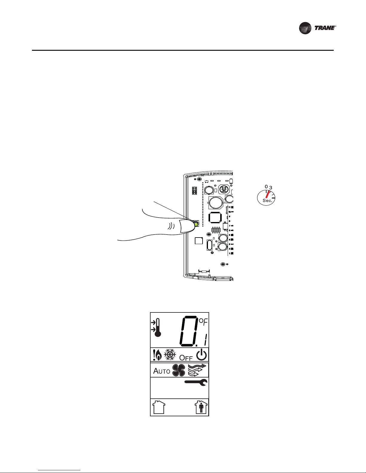
Configuring the Display Sensor
Configuration button
The configuration of the display sensor determines which system features can be accessed and
changes can be made by the tenant (for example, changes to cooling/heating mode, setpoint, or
fan speed. Verify system and associated unit features before configuring the sensor.
The building owner or operator may choose to limit tenant access to certain features. This can be
done through configuration. Or, if a sensor is configured to match all controllable features of the
associated equipment, the locking feature can be used to restrict the tenant from making changes.
Configuration Procedure
To configure settings on the sensor, follow this procedure in the order presented.
1. Press the configuration button for 3 seconds.
Installation and Configuration: Display Sensor
The display will change to configuration mode. When the sensor is in configuration mode, a wrench
symbol appears on the display and the menus are separated by lines, as illustrated below.
BAS-SVX10C-EN 11
Center button
. .
.
.
.
.
dual setpoint
no
single
heat/cool setpoint offset
2ºF – 10.8ºF, 1.1ºC – 6ºC
Installation and Configuration: Display Sensor
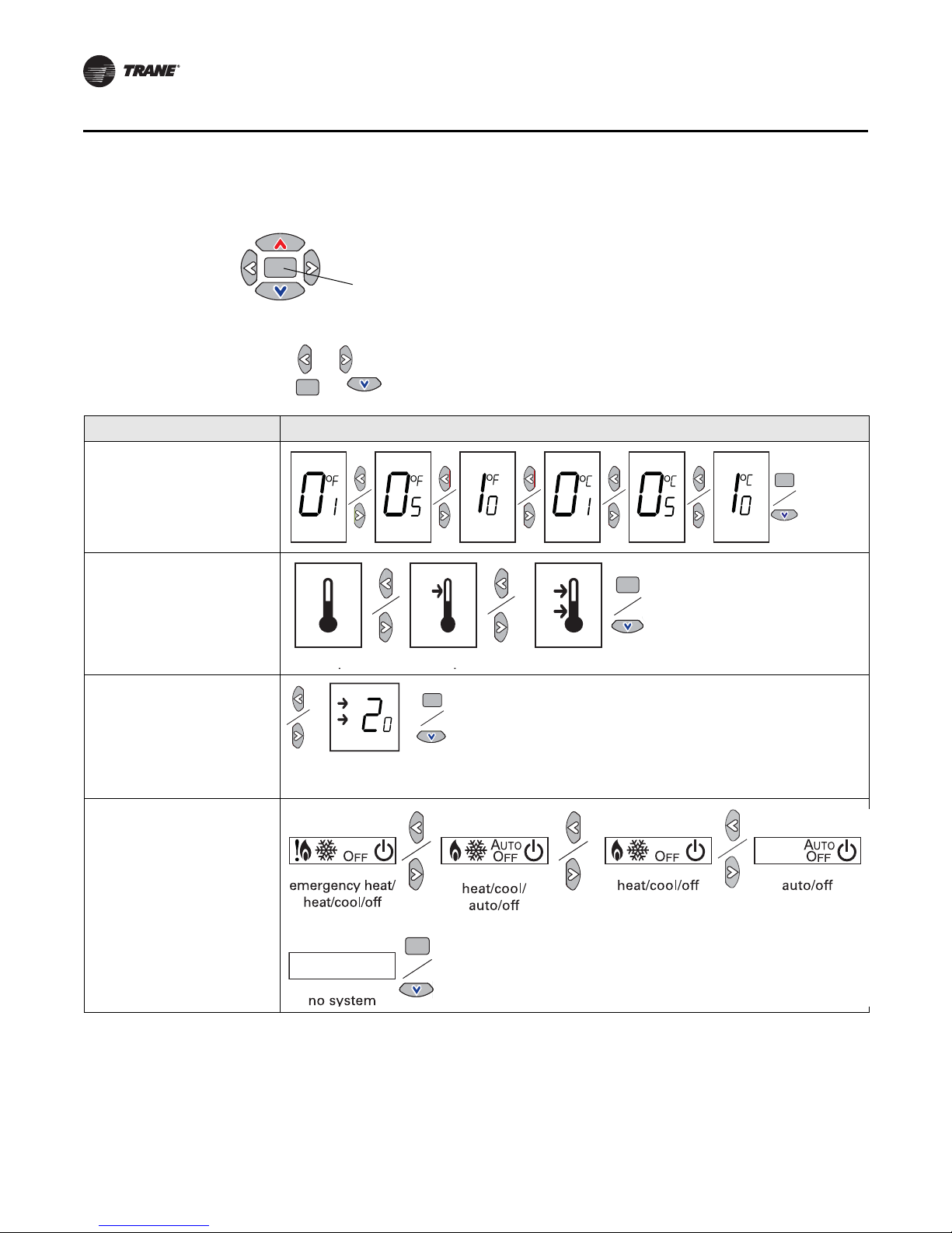
1. Press the center button on the keypad to begin the configuration process.
2. Configure the sensor options in the order shown in the table.
• Press or to scroll to the next selection (as illustrated).
• Press or to move to the next menu (as illustrated).
Setting Configuration options
Temperature
• Choose Fahrenheit or Celsius
• Choose the degree resolution
(whole degrees, half degrees, or
tenths of degrees)
Setpoint
Deadband (available for dual
setpoint system only)
Note: Deadband refers to the
minimum difference between
the heating and cooling
setpoints.
System
a) Single setpoint
.
heat/cool setpoint offset
(1.8˚F – 10.8˚F, 1˚C – 6˚C)
12 BAS-SVX10C-EN
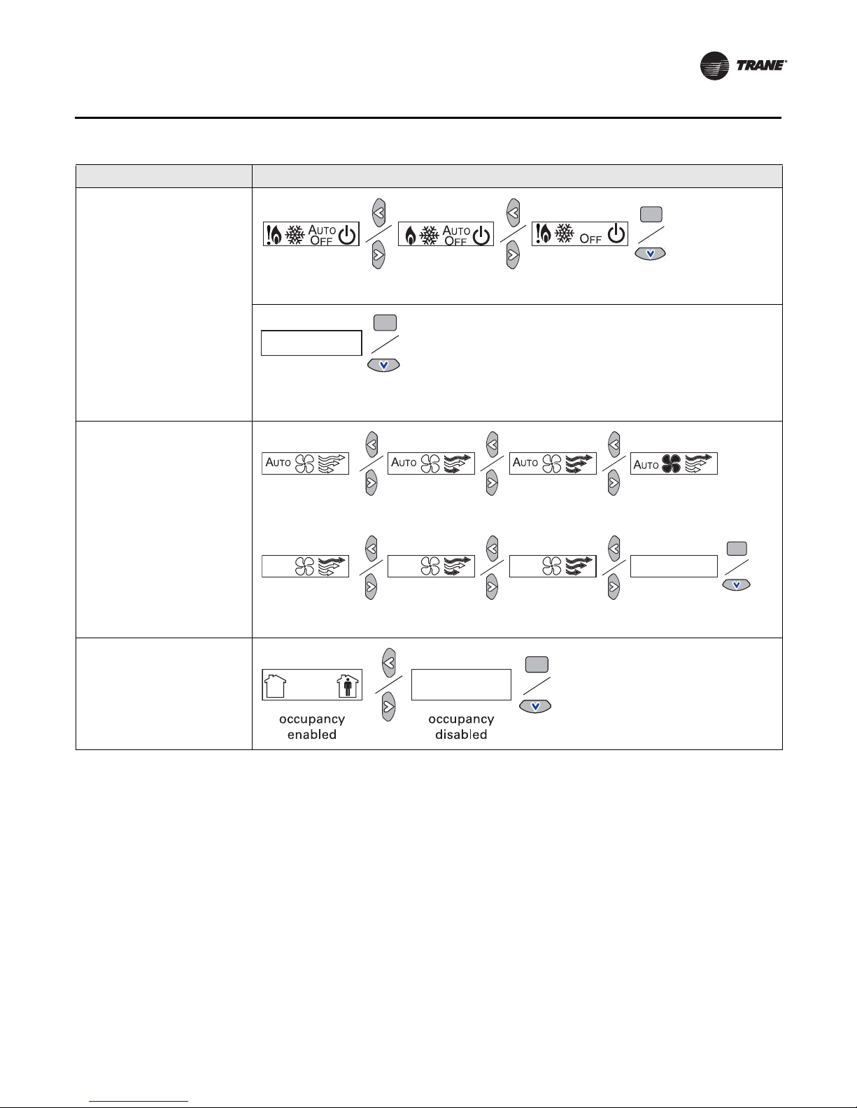
Setting Configuration options
emergency heat/
heat/cool/off
heat/cool/
auto/off
emergency heat/
heat/cool/auto/off
no system
options enabled
auto/off/low
med/high
auto/off/
low/high
auto/off
off/high (on)
off/low/high off/low/
med/high
no fan options
enabled
auto/high (on)
System (continued)
b) Dual setpoint
c) No setpoint
Fan
Installation and Configuration: Display Sensor
Note: Not all fan options are
available for all systems.
Occupancy (timed override)
BAS-SVX10C-EN 13
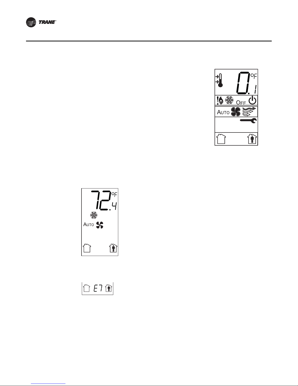
The example shows a display that has been configured for:
• Dual setpoint
• Temperature units (Fahrenheit)
• Temperature resolution to tenths of a degree
• System settings: Emergency Heat, Heat, Cool, Off
• Fan settings: Auto or On
• Occupied/unoccupied option enabled
Display shows the following:
• Temperature units (Fahrenheit)
• Temperature resolution to tenths of a degree
• System setting: Cooling
• Fan setting: Auto
• Occupied/unoccupied option enabled
Installation and Configuration: Display Sensor
1. Review the display to ensure that you have selected the correct configuration options.
2. To return the display to operating mode, press the configuration button (see step 1, p. 11).
Note: The sensor will revert to operating mode if no buttons are pressed for 10 minutes.
The following example shows a configured display in operating mode.
If an error code exists, it appears at the bottom of the display between the occupancy symbols,
as shown below. See “Error codes,” p. 28, for error code definitions.
14 BAS-SVX10C-EN
 Loading...