

Trane WZS, X13790496, X13790498, X13790492, X13790494 Installation & Operation Manual
...
Installation, operation, and
maintenance
Wireless Zone Sensor
Model WZS
June 2006 BAS-SVX04A-EN


This guide and the information in it are the property of American Standard and may not be used or
reproduced in whole or in part, without the written permission of American Standard. Trane, a
business of American Standard, Inc, has a policy of continuous product and product data improvement
and reserves the right to change design and specification without notice.
Although Trane has tested the hardware and software described in this guide, no guarantee is offered
that the hardware and software are error free.
Trane reserves the right to revise this publication at any time and to make changes to its content
without obligation to notify any person of such revision or change.
Trane may have patents or patent applications covering items in this publication. By providing this
document, Trane does not imply giving license to these patents.
The following are trademarks or registered trademarks of American Standard: Trane.
®
™
The following are trademarks or registered trademarks of their respective companies or
®
™
organizations: Energizer of Eveready Battery Company, Inc.; LonTalk of Echelon Corporation;
Velcro of Velcro Industries B.V.
© 2006 American Standard All rights reserved BAS-SVX04A-EN

Warnings and Cautions
Warnings and Cautions. Notice that warnings and cautions appear at
appropriate intervals throughout this manual. Warnings are provided to alert
installing contractors to potential hazards that could result in personal injury or
death, while cautions are designed to alert personnel to conditions that could
result in equipment damage.
Your personal safety and the proper operation of this machine depend upon the
strict observance of these precautions.
NOTICE: Warnings and Cautions appear at appropriate sections throughout this
literature. Read these carefully.
WAR NIN G: Indicates a potentially hazardous situation which, if not avoided,
could result in death or serious injury.
CAUTION: Indicates a potentially hazardous situation which, if not avoided,
may result in minor or moderate injury. It may also be used to alert against
unsafe practices.
CAUTION: Indicates a situation that may result in equipment or property-
damage only accidents.
© 2006 American Standard Inc All rights reserved BAS-SVX04A-EN

Contents
Product Description . . . . . . . . . . . . . . . . . . . . . . . . . . . . . . . . . . . . . . . . . . . . . . . . 9
Overview . . . . . . . . . . . . . . . . . . . . . . . . . . . . . . . . . . . . . . . . . . . . . . . . . . . . . . . . 9
Factory or Field Installed . . . . . . . . . . . . . . . . . . . . . . . . . . . . . . . . . . . . . . . . . . 9
Part Numbers . . . . . . . . . . . . . . . . . . . . . . . . . . . . . . . . . . . . . . . . . . . . . . . . . . 9
Dimensional Diagrams . . . . . . . . . . . . . . . . . . . . . . . . . . . . . . . . . . . . . . . . . . . . . 9
Setting the Address, Mounting, Wiring, and Associating the Receiver and
Sensor
. . . . . . . . . . . . . . . . . . . . . . . . . . . . . . . . . . . . . . . . . . . . . . . . . . . . . . . . . . . .13
Choosing a Location for Mounting the Receiver and Sensor . . . . . . . . . . . . . 13
Location Considerations for the Receiver . . . . . . . . . . . . . . . . . . . . . . . . . . . . .13
Location Considerations for the Sensor . . . . . . . . . . . . . . . . . . . . . . . . . . . . . .14
Setting the Rotary Address Switches on the Receiver and the Sensor . . . . . 15
Setting the Receiver Address . . . . . . . . . . . . . . . . . . . . . . . . . . . . . . . . . . . . . .16
Setting the Sensor Address . . . . . . . . . . . . . . . . . . . . . . . . . . . . . . . . . . . . . . .16
Mounting the Base Plate of the Receiver . . . . . . . . . . . . . . . . . . . . . . . . . . . . . 17
Wiring the Receiver to the Unit Controller . . . . . . . . . . . . . . . . . . . . . . . . . . . . 18
Power Requirements. . . . . . . . . . . . . . . . . . . . . . . . . . . . . . . . . . . . . . . . . . . . 18
Wiring Procedures. . . . . . . . . . . . . . . . . . . . . . . . . . . . . . . . . . . . . . . . . . . . . . 18
Transformer Wiring. . . . . . . . . . . . . . . . . . . . . . . . . . . . . . . . . . . . . . . . . . . . . 22
Replacing and Securing the Receiver Cover . . . . . . . . . . . . . . . . . . . . . . . . . . 24
Applying Power to the Receiver . . . . . . . . . . . . . . . . . . . . . . . . . . . . . . . . . . . . 25
Receiver Indicates Readiness to Associate . . . . . . . . . . . . . . . . . . . . . . . . . . . . 25
Powering the Sensor and Associating the Sensor to the Receiver . . . . . . . . 26
Testing Signal and Battery Strength . . . . . . . . . . . . . . . . . . . . . . . . . . . . . . . . . 27
Automatic Association . . . . . . . . . . . . . . . . . . . . . . . . . . . . . . . . . . . . . . . . . . . . 28
Manual Association . . . . . . . . . . . . . . . . . . . . . . . . . . . . . . . . . . . . . . . . . . . . . . 28
Disassociation . . . . . . . . . . . . . . . . . . . . . . . . . . . . . . . . . . . . . . . . . . . . . . . . . . . 28
Mounting the Base Plate of the Sensor . . . . . . . . . . . . . . . . . . . . . . . . . . . . . . 29
To Mount Sensor Directly to Drywall or Plaster . . . . . . . . . . . . . . . . . . . . . . . 29
To Mount Sensor Directly to an Electrical Junction Box . . . . . . . . . . . . . . . . 30
Replacing and Securing the Sensor Cover . . . . . . . . . . . . . . . . . . . . . . . . . . . . 30
Operation, Maintenance, and Troubleshooting . . . . . . . . . . . . . . . . . . . . . . 31
LED Operation . . . . . . . . . . . . . . . . . . . . . . . . . . . . . . . . . . . . . . . . . . . . . . . . . . . 31
Signal Quality Test . . . . . . . . . . . . . . . . . . . . . . . . . . . . . . . . . . . . . . . . . . . . . 32
Diagnostics . . . . . . . . . . . . . . . . . . . . . . . . . . . . . . . . . . . . . . . . . . . . . . . . . . . 33
Sensor Battery Status Test and Low Battery Power Notification . . . . . . . . . . 34
24 V Power Status . . . . . . . . . . . . . . . . . . . . . . . . . . . . . . . . . . . . . . . . . . . . . . 34
Sensor Batteries . . . . . . . . . . . . . . . . . . . . . . . . . . . . . . . . . . . . . . . . . . . . . . . . . 35
Battery Type . . . . . . . . . . . . . . . . . . . . . . . . . . . . . . . . . . . . . . . . . . . . . . . . . . 35
Battery Life . . . . . . . . . . . . . . . . . . . . . . . . . . . . . . . . . . . . . . . . . . . . . . . . . . . 36
Battery Installation . . . . . . . . . . . . . . . . . . . . . . . . . . . . . . . . . . . . . . . . . . . . . 36
Occupied (On)/Unoccupied (Cancel) Button Operation . . . . . . . . . . . . . . . . . . 37
Special Thumbwheel Operation . . . . . . . . . . . . . . . . . . . . . . . . . . . . . . . . . . . . 38
Using the Wireless Zone Sensor System as a Site Survey Tool to Check Signal
Quality . . . . . . . . . . . . . . . . . . . . . . . . . . . . . . . . . . . . . . . . . . . . . . . . . . . . . . . . . 38
Output Power Level . . . . . . . . . . . . . . . . . . . . . . . . . . . . . . . . . . . . . . . . . . . . . . 38
BAS-SVX04A-EN 5

Contents
Output Failure Modes of Operation . . . . . . . . . . . . . . . . . . . . . . . . . . . . . . . . . 39
Output Default Mode . . . . . . . . . . . . . . . . . . . . . . . . . . . . . . . . . . . . . . . . . . . . . 39
Measuring Output Resistance . . . . . . . . . . . . . . . . . . . . . . . . . . . . . . . . . . . . . . 40
End-of-Range Temperature Values . . . . . . . . . . . . . . . . . . . . . . . . . . . . . . . . . . 40
Receiver Power-up Sequence . . . . . . . . . . . . . . . . . . . . . . . . . . . . . . . . . . . . . . 41
Sensor Transmission Time and Temperature Variables. . . . . . . . . . . . . . . . . 42
Time Variables. . . . . . . . . . . . . . . . . . . . . . . . . . . . . . . . . . . . . . . . . . . . . . . . . 42
Temperature Variables . . . . . . . . . . . . . . . . . . . . . . . . . . . . . . . . . . . . . . . . . . 42
Servicing and Testing. . . . . . . . . . . . . . . . . . . . . . . . . . . . . . . . . . . . . . . . . . . . . 43
Servicing and Testing Tools . . . . . . . . . . . . . . . . . . . . . . . . . . . . . . . . . . . . . . 43
Procedure for the Testing the Wireless Zone Sensor System . . . . . . . . . . . . 43
Procedure for Testing the Receiver. . . . . . . . . . . . . . . . . . . . . . . . . . . . . . . . . 43
Returning a Sensor to its Factory Defaults . . . . . . . . . . . . . . . . . . . . . . . . . . . 44
Returning a Receiver to its Factory Defaults. . . . . . . . . . . . . . . . . . . . . . . . . . 44
Replacing a Defective Sensor or Receiver . . . . . . . . . . . . . . . . . . . . . . . . . . . 44
Forcing a Sensor to Transmit . . . . . . . . . . . . . . . . . . . . . . . . . . . . . . . . . . . . . 44
Specifications and Agency Compliance . . . . . . . . . . . . . . . . . . . . . . . . . . . . . 45
Specifications . . . . . . . . . . . . . . . . . . . . . . . . . . . . . . . . . . . . . . . . . . . . . . . . . . . 45
Agency Compliance . . . . . . . . . . . . . . . . . . . . . . . . . . . . . . . . . . . . . . . . . . . . . . 46
6 BAS-SVX04A-EN

Literature Change History
Document Number Date Description
BAS-SVX04A-EN June 2006 New
BAS-SVX04A-EN 7

8 BAS-SVX04A-EN
Product Description
This manual contains information about installing, operating, and maintaining
the Trane
Overview
The Trane Wireless Zone Sensor set includes a sensor and a receiver that work
together to provide the same functions as the equivalent Trane wired sensor
(#4190-1090), such as the standard 10 kΩ temperature input (with the exception of
the communication jack). No further software or hardware is necessary for site
evaluation, installation, or maintenance.
The sensor transmits the zone temperature, all zone temperature setpoint
functions, timed override Occupied (On) and timed override Unoccupied (Cancel)
information to the receiver. The receiver electrically reproduces the zone
temperature resistance, all zone temperature setpoint function resistances, and
timed override On and timed override Cancel information as sent by the sensor.
Factory or Field Installed
The information in this manual is applicable to Wireless Zone Sensor sets that
are either factory or field installed.
®
Wireless Zone Sensor system.
Part Numbers
Table 1. Part numbers
Part number Description
X13790496 Wireless Zone Sensor set, North America (100 mW, 16 channel),
X13790498 Wireless Zone Sensor set, North America (100 mW, 16 channel),
X13790492 Sensor only, Fahrenheit
X13790494 Sensor only, Celsius
X13790488 Receiver only, North America (100 mW, 16 channels), analog
X13790489 Receiver only, Europe (10 mW, 16 channels), analog
X19051672 Wire harness, five-conductor, for wireless receiver (all locations)
Dimensional Diagrams
See Figure 1, p. 10 and Figure 2, p. 11 for dimensions of the Wireless Zone Sensor
set. The dimensions are the same for both the sensor and the receiver.
Fahrenheit, analog
Celsius, analog
(Not advised for North America.)
BAS-SVX04A-EN • Wireless Zone Sensor 9

Product Description
Figure 1. Outside dimensions for sensor and receiver
4.78 in (12.14 cm)
2.90 in (7.35 cm)
1.08 in (2.75 cm)
10 Wireless Zone Sensor • BAS-SVX04A-EN
2.62 in (6.65 cm)
Note: The dimensions are the
same for both the sensor
and the receiver.
Product Description
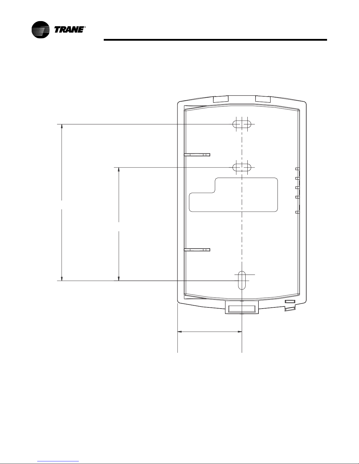
Figure 2. Mounting hole dimensions for sensor and receiver
3.27 in (8.30 cm)
2.36 in (6.00 cm)
1.34 in (3.41 cm)
Note: The dimensions are the
same for both the sensor
and the receiver.
BAS-SVX04A-EN • Wireless Zone Sensor 11

Product Description
12 Wireless Zone Sensor • BAS-SVX04A-EN

Setting the Address, Mounting, Wiring,
and Associating the Receiver and
Sensor
The following procedure list shows the recommended order for installation:
• Choosing a location for mounting the receiver and sensor
• Setting the rotary switches on the receiver and the sensor
• Mounting the base plate of the receiver
• Wiring the receiver to the unit controller
• Replacing and securing the receiver cover
• Applying power to the receiver
• Powering the sensor and associating the sensor to the receiver
• Testing signal and battery strength
• Automatic association
• Manual association
• Mounting the base plate of the sensor
• Replacing and securing the sensor cover
Choosing a Location for Mounting the Receiver and Sensor
Placement of the receiver and the sensor set is critical to proper operation. In
most installations, distance is not the limiting factor for proper radio signal
quality. It is more greatly affected by walls, barriers, and general clutter. For best
radio transmission range and reliability, wherever possible, mount the receiver
and sensor in line of sight. Try to minimize the number of barriers between the
pair of devices. In general, sheetrock walls and ceiling tiles offer little restriction
to the propagation of the radio signal throughout the building; concrete or metal
barriers offer the most restriction.
The transmission range for the sensor is as follows:
• Open range: 2,500 ft (762 m) (packet error rate = 2%)
• Usable range: 200 ft (61 m)
• Typical range: 75 ft (23 m)
Location Considerations for the Receiver
When selecting a location for the receiver, consider both ambient and radio
transmission characteristics of the location.
Ambient considerations
• Avoid locations that are outside the operating temperature and humidity
range (refer to
BAS-SVX04A-EN • Wireless Zone Sensor 13
Ta bl e 11, p . 45).

Setting the Address, Mounting, Wiring, and Associating the
Receiver and Sensor
Radio transmission considerations
• Avoid metal barriers between the receiver and the sensor; they decrease
radio signal quality significantly (for example, plastered walls with metal
lathe or metal roof decks).
• Avoid placing the receiver inside metal enclosures.
• Avoid radio transmissions through thick, solid concrete walls.
• Conduct rooftop mounting and operation of the receiver only after careful
site evaluation and confirmation.
Location Considerations for the Sensor
When selecting a location for the sensor, consider both thermal and radio
transmission characteristics of the location.
Thermal considerations
• Avoid areas of direct sunlight.
• Avoid areas in the direct airstream of air diffusers.
• Avoid exterior walls and other walls that have a temperature differential
between their two sides.
• Avoid areas close to sources of heat such as sunlight, appliances, or other
equipment.
• Avoid drafty areas.
• Avoid dead spots behind doors, projection screens, or corners.
Radio transmission considerations
• Avoid metal barriers between the sensor and receiver, such as plastered walls
with metal lathe. They will decrease radio signal quality.
• Avoid placing the sensor inside metal enclosures.
• Avoid radio transmissions through thick, solid concrete walls.
14 Wireless Zone Sensor • BAS-SVX04A-EN
Setting the Address, Mounting, Wiring, and Associating the
ADDRESS
IN
LED3
LED2
A
Receiver and Sensor
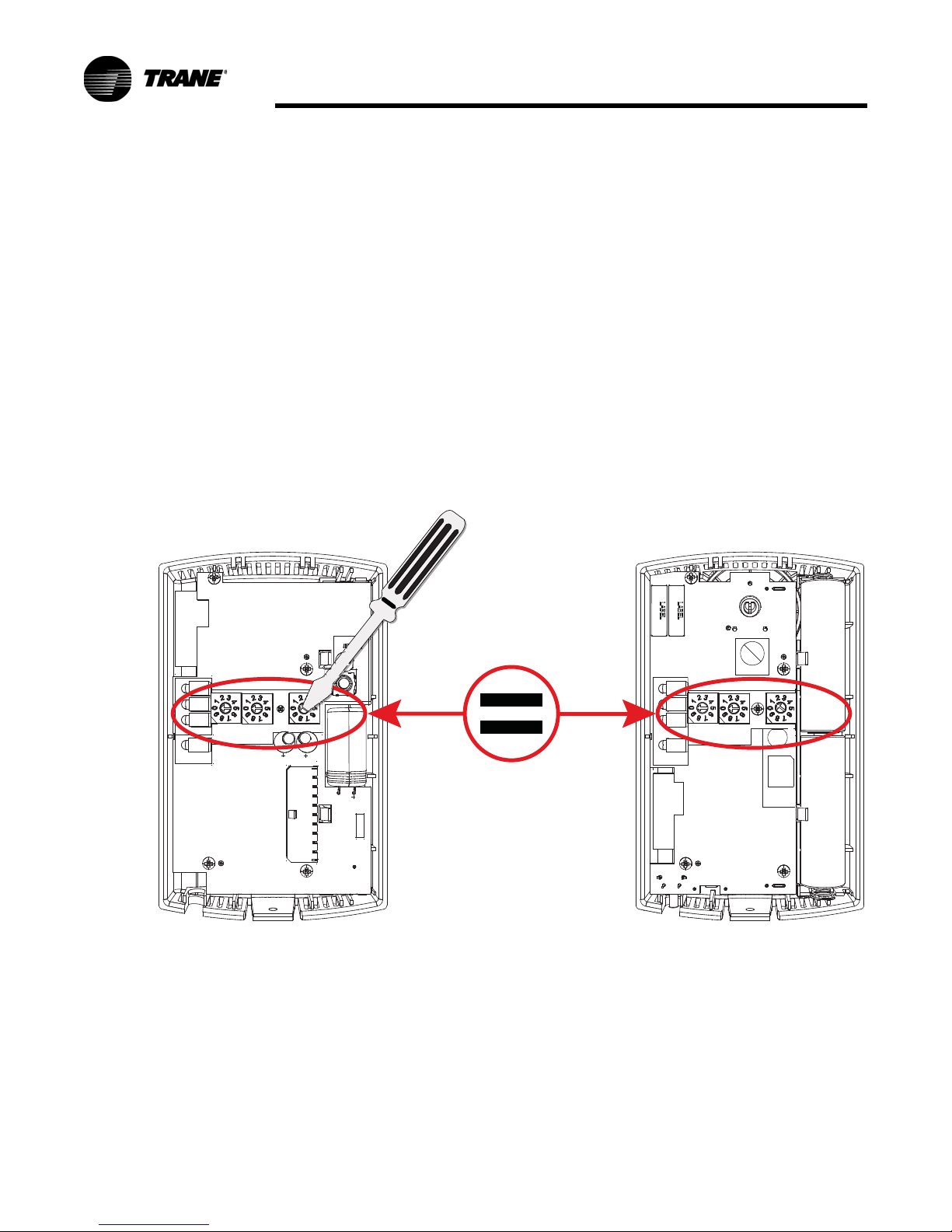
Setting the Rotary Address Switches on the Receiver and the Sensor
Note: To expedite the installation and association process, set the addresses
before applying power to the receiver.
The process of establishing communication between the receiver and sensor is
referred to as association. The receiver and the sensor must have their rotary
switches set to the same address in order to enable communication between the
two devices (see Figure 3). Important limitations are as follows:
• Only one associated receiver/sensor set can communicate within the
reception range of the wireless system.
• It is not possible to associate more than one sensor to a receiver, nor is it
possible to associate more than one receiver to a sensor.
Figure 3. Setting the rotary address switches on the receiver and the sensor
LED1
LED2
LED3
LED5
SIGNAL
POWER
S5
S1
A
RECEIVER
1
J2
S2
HEATING SET
FAN/SYSTEM
SETPOINT
ZONE
GND
24VAC/DC
GND
COMM +
COMM -
S3
C33
C34
J1
WIRELESS
TALL
LED4
R77
!
S4
C35
Each pair of devices must
have a unique address.
Range 001 - 999
LED1
SIGNAL
LED5
BATTERY
STATUS
SENSOR
Pb
Pb-FREE
S1
ADDRESS
S3
S2
S4
J1
B1 +
STATUS
WIRELESS
INSTALL
B2 -
LED4
BAS-SVX04A-EN • Wireless Zone Sensor 15
 Loading...