

Trane WTK507, WTK509, WTK Series, WTK512, WTK518 Installation Manual
...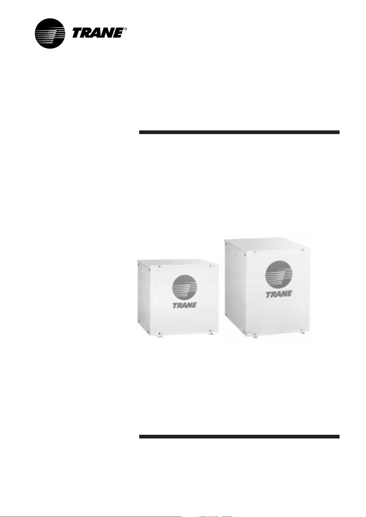
Installation Manual
Split Water-Cooled
Condensing Units
7,000 - 60,000 Btu/h
WTK Series 50 Hz
50Hz Models
Cooling Only
WTK507
WTK509
WTK512
WTK518
WTK524
WTK530
WTK536
WTK048
WTK060
April 2004
WTK-SVN001-EN
General Information
Introduction
This Installation Manual is given
as a guide to good practice in the
installation by the installer of mini-split
system. Installation procedures should
be performed in the sequence that
they appear in this manual.
For installing the unit to operate
properly and reliably, it must be
installed in accordance with these
instructions. Also, the services of a
qualified service technician should be
employed, through the maintenance
contract with a reputable service
company.
Read these Installation Manual
completely before installing the
condensing unit.
About the Unit
The units are assembled, pressure
tested, dehydrated, charged and run
tested before shipment. The information
contained in this manual applies to
units that are designed to operate in
cooling mode only.
Important
This document is customer property
and is to remain with unit. Please place
in service information pack upon
completion of work. These instructions
do not cover all variations in systems,
nor do they provide for every possible
contingency to be met in connection
with installation. Should further
information be desired or should
particular problems arise which are
not covered sufficiently in this manual,
the matter should be referred to your
Trane sales representative.
Reception
On arrival, inspect the unit before
signing the delivery note. Verify that
the nameplate data matches the date
on the sales order, submittal data and
delivery note (including electrical data)
to insure the proper unit was shipped.
Specify any damage of the unit on the
delivery note, and send a registered
letter of protest to the last carrier of
the goods within 72 hours of delivery.
Notify the dealer at the same time.
The unit should be totally inspected
within 7 days of delivery. If any
concealed damage is discovered,
send a registered letter of protest to
the carrier within 7 days of delivery
and notify the dealer.
Warranty
Warranty is based on the general
terms and conditions by country.
The warranty is void if the equipment
is modified or repaired without the
written approval of The Trane Company,
if the operating limits are exceeded or
if the control system or the electrical
wiring is modified. Damage due to
inappropriate installation, lack of
knowledge or failure to comply with
the manufacturer’s instructions, is not
covered by the warranty obligation.
If the installer does not conform to the
rules described in Installation Manual,
it may entail cancellation of warranty
and liabilities by The Trane Company.
Storage
Take precautions to prevent
condensate from forming inside the
unit’s electrical board and motors
if the unit is stored before it is installed.
The Trane Company will not assume
any responsibility for unit damage
resulting from condensate
accumulation on the unit’s electrical
and/or mechanical components.
About this Manual
Cautions and warnings appear at
appropriate places in this instruction
manual. Your personal safety and the
proper operation of this machine
require that you follow them carefully.
The Trane Company assumes no
liability for installations or servicing
performed by unqualified personnel.
All phases of the installation of this
air conditioning system must conform
to all national, provincial, state and
local codes.
Warning
Warnings are provided at appropriate
places in this manual to indicate to
installers, operators and service
personnel of potentially hazardous
situations which, if not avoided,
COULD result in death or serious
injury.
Caution
Cautions are provided at appropriate
places in this manual to indicate to
installers, operators, and service
personnel of potentially hazardous
situations which, if not avoided,
MAY result in minor or moderate
injury or malfunction of the unit.
2
© American Standard Inc. 2003
WTK-SVN001-EN
Contents
General Information 2
Model Nomenclature 4
Location and Preparation of Unit 5
Refrigerant Tube Size Selection 5
Connection of Refrigerant Tubing
(Flaring and Brazing Procedure) 6
Water Pipe Connection 8
Gas Leakage Inspection 9
Air Evacuation and Refrigerant Charge 10
Wiring and System Inspection
before Test Run 11
Condenser Cleaning 11
Wiring Diagram 12
Dimensional Data 14
WTK-SVN001-EN
3
Model Nomenclature
W T K 5 0 7 A B 0 0 B A
123456789101112
Digit No. 1 = Product Type
W=Split Water Cooled Condensing Unit
Digit No. 2
T=Cooling Only
W=Heat Pump
Digit No. 3 = Refrigerant Circuit(s)/Compressor(s)
K=Single Refrigerant Circuit/Compressor
D=Dual Refrigerant Circuits/Compressors
T=Tr iple Refrigerant Circuits/Compressors
(Others to be determined as needed.)
Digit No. 4 = Refrigerant Connection Type
0=Sweat (Brazed)
5=Flared (Tubing)
7=Quick Connect
Digit No. 5 and No. 6 = Nominal Capacity
Btu/h X 1000
(Note: Exact system capacities/performance when matched with selected indoor
unit are specified in Product Catalogs.)
Digit No. 7 = Major Development Sequence
Digit No. 8 = Electric Power Supply Characteristics
A=220V/1ph/50Hz or 200-220V/1ph/50Hz
B=240V/1ph/50Hz or 220-240V/1ph/50Hz
1=220V/1ph/60Hz or 200-240V/1ph/60Hz
3=200-240V/3ph/60Hz
D=380-415V/3ph/50Hz
4=460V/3ph/60Hz
Digit No. 9 and 10 = Factory Installed Options
(Note: The Alphabetic Letter “O” is not used in digit 9 or 10, Only the Number “0”
is used.)
00 = No option
0E = 3 minute time delay (for use w/ MCD)
0F = Hi/Lo Pressure Cut Off
0G = 3 minute time delay + Hi/Lo Pressure Cut Off
0S = Special request to be provided in wording and to be approved by factory
i.e. service valve at the water side, insulation on suction line, emergency stop.
Digit No. 11 = Minor Design Sequence/Series - Design Change
Alphabetic Letter, “A” through “Z”
Digit No. 12 = Service Digit
4
WTK-SVN001-EN
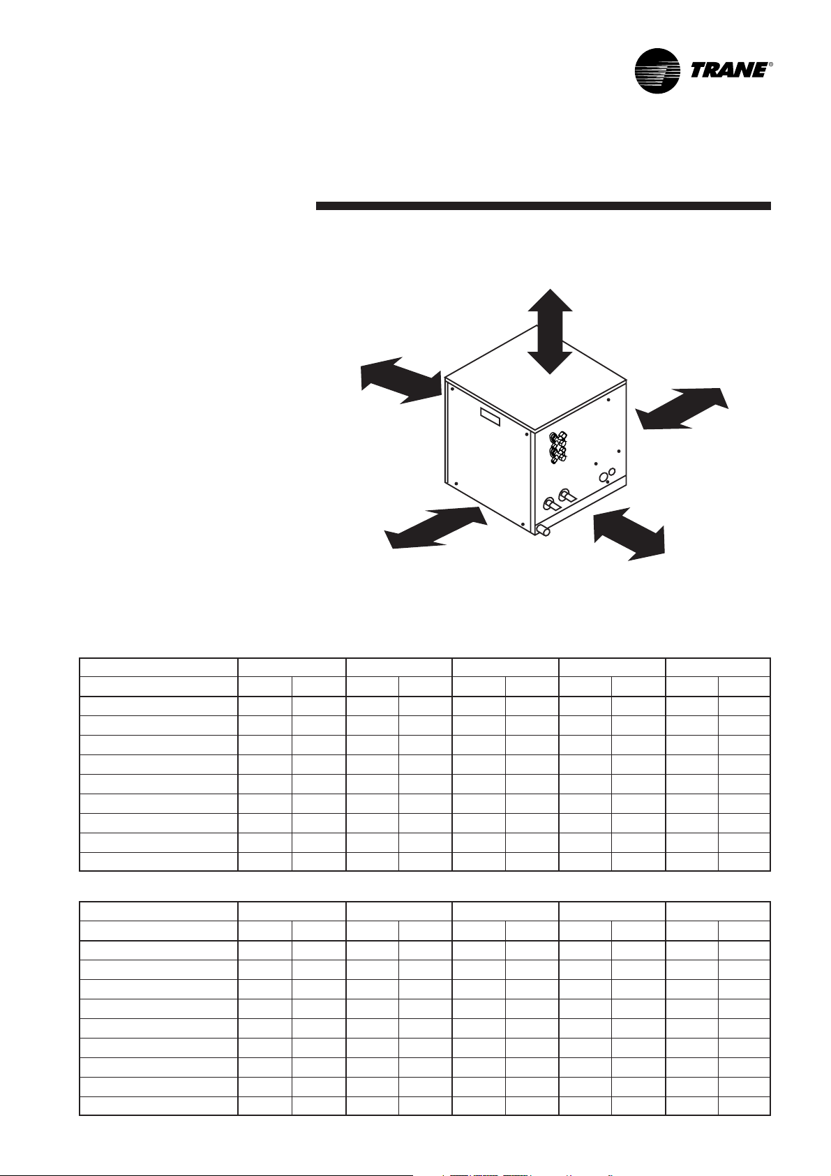
Location and Preparation of Unit
Installation of Condensing Unit at
More than 15 cm
the appropriate places
• The place where is not near the
gas area of potentially hazardous
situations.
More than 10 cm
•Isolated place to avoid noise and
heat disturbing to neighbourhood
• Convenient places for inspection
More than 35 cm
or reparation
Refrigerant Tube Size Selection
To select tube size is necessary to
consider many factors such as:
velocity of refrigerant, number of tube
connector, bended joint and length of
refrigerant tube. Therefore, for quick
selection size of refrigerant tube,
see the detail below:-
Refrigerant tube size for Trane
More than 35 cm
Air-conditioning (size 7,000-60,000 Btu/h)
Figure 1
Domestic
Tubing Length (m) /Tubing size (inch) Minimum 12 m 13 - 18 m 19 - 24 m 25 - 30 m 31 - 36 m
Model Liquid Line Suction Line Liquid Line Suction Line Liquid Line Suction Line Liquid Line Suction Line Liquid Line Suction Line
WTK507 1/4 3/8 1/4 3/8 1/4 3/8 1/4 1/2 1/4 1/2
WTK509 1/4 3/8 1/4 3/8 1/4 3/8 1/4 1/2 1/4 1/2
WTK512 3/8 5/8 3/8 5/8 3/8 5/8 3/8 5/8 3/8 5/8
WTK518 3/8 5/8 3/8 5/8 3/8 5/8 3/8 5/8 3/8 5/8
WTK524 3/8 5/8 3/8 5/8 3/8 3/4 3/8 3/4 3/8 3/4
WTK530 3/8 5/8 3/8 5/8 3/8 3/4 3/8 3/4 3/8 3/4
WTK536 3/8 3/4 3/8 3/4 3/8 3/4 3/8 7/8 3/8 7/8
WTK048 1/2 7/8 1/2 7/8 1/2 7/8 1/2 7/8 1/2 1 1/8
WTK060 1/2 7/8 1/2 7/8 1/2 1 1/8 1/2 1 1/8 1/2 1 1/8
More than 35 cm
Export
Tubing Length (m) /Tubing size (inch) Minimum 12 m 13 - 18 m 19 - 24 m 25 - 30 m 31 - 36 m
Model Liquid Line Suction Line Liquid Line Suction Line Liquid Line Suction Line Liquid Line Suction Line Liquid Line Suction Line
WTK507 1/4 3/8 1/4 3/8 1/4 3/8 1/4 1/2 1/4 1/2
WTK509 1/4 3/8 1/4 3/8 1/4 3/8 1/4 1/2 1/4 1/2
WTK512 1/4 1/2 1/4 1/2 1/4 1/2 1/4 1/2 1/4 1/2
WTK518 1/4 1/2 3/8 5/8 3/8 5/8 3/8 5/8 3/8 5/8
WTK524 3/8 5/8 3/8 5/8 3/8 3/4 3/8 3/4 3/8 3/4
WTK530 3/8 5/8 3/8 5/8 3/8 3/4 3/8 3/4 3/8 3/4
WTK536 3/8 3/4 3/8 3/4 3/8 3/4 3/8 7/8 3/8 7/8
WTK048 3/8 1 1/8 3/8 1 1/8 3/8 1 1/8 3/8 1 1/8 3/8 1 1/8
WTK060 3/8 1 1/8 3/8 1 1/8 3/8 1 1/8 3/8 1 1/8 3/8 1 1/8
WTK-SVN001-EN
5
 Loading...