

Page 1
Installation Manual
Split Water-Cooled
Condensing Units
7,000 - 60,000 Btu/h
WTK Series 50 Hz
50Hz Models
Cooling Only
WTK507
WTK509
WTK512
WTK518
WTK524
WTK530
WTK536
WTK048
WTK060
April 2004
WTK-SVN001-EN
Page 2
General Information
Introduction
This Installation Manual is given
as a guide to good practice in the
installation by the installer of mini-split
system. Installation procedures should
be performed in the sequence that
they appear in this manual.
For installing the unit to operate
properly and reliably, it must be
installed in accordance with these
instructions. Also, the services of a
qualified service technician should be
employed, through the maintenance
contract with a reputable service
company.
Read these Installation Manual
completely before installing the
condensing unit.
About the Unit
The units are assembled, pressure
tested, dehydrated, charged and run
tested before shipment. The information
contained in this manual applies to
units that are designed to operate in
cooling mode only.
Important
This document is customer property
and is to remain with unit. Please place
in service information pack upon
completion of work. These instructions
do not cover all variations in systems,
nor do they provide for every possible
contingency to be met in connection
with installation. Should further
information be desired or should
particular problems arise which are
not covered sufficiently in this manual,
the matter should be referred to your
Trane sales representative.
Reception
On arrival, inspect the unit before
signing the delivery note. Verify that
the nameplate data matches the date
on the sales order, submittal data and
delivery note (including electrical data)
to insure the proper unit was shipped.
Specify any damage of the unit on the
delivery note, and send a registered
letter of protest to the last carrier of
the goods within 72 hours of delivery.
Notify the dealer at the same time.
The unit should be totally inspected
within 7 days of delivery. If any
concealed damage is discovered,
send a registered letter of protest to
the carrier within 7 days of delivery
and notify the dealer.
Warranty
Warranty is based on the general
terms and conditions by country.
The warranty is void if the equipment
is modified or repaired without the
written approval of The Trane Company,
if the operating limits are exceeded or
if the control system or the electrical
wiring is modified. Damage due to
inappropriate installation, lack of
knowledge or failure to comply with
the manufacturer’s instructions, is not
covered by the warranty obligation.
If the installer does not conform to the
rules described in Installation Manual,
it may entail cancellation of warranty
and liabilities by The Trane Company.
Storage
Take precautions to prevent
condensate from forming inside the
unit’s electrical board and motors
if the unit is stored before it is installed.
The Trane Company will not assume
any responsibility for unit damage
resulting from condensate
accumulation on the unit’s electrical
and/or mechanical components.
About this Manual
Cautions and warnings appear at
appropriate places in this instruction
manual. Your personal safety and the
proper operation of this machine
require that you follow them carefully.
The Trane Company assumes no
liability for installations or servicing
performed by unqualified personnel.
All phases of the installation of this
air conditioning system must conform
to all national, provincial, state and
local codes.
Warning
Warnings are provided at appropriate
places in this manual to indicate to
installers, operators and service
personnel of potentially hazardous
situations which, if not avoided,
COULD result in death or serious
injury.
Caution
Cautions are provided at appropriate
places in this manual to indicate to
installers, operators, and service
personnel of potentially hazardous
situations which, if not avoided,
MAY result in minor or moderate
injury or malfunction of the unit.
2
© American Standard Inc. 2003
WTK-SVN001-EN
Page 3

Contents
General Information 2
Model Nomenclature 4
Location and Preparation of Unit 5
Refrigerant Tube Size Selection 5
Connection of Refrigerant Tubing
(Flaring and Brazing Procedure) 6
Water Pipe Connection 8
Gas Leakage Inspection 9
Air Evacuation and Refrigerant Charge 10
Wiring and System Inspection
before Test Run 11
Condenser Cleaning 11
Wiring Diagram 12
Dimensional Data 14
WTK-SVN001-EN
3
Page 4
Model Nomenclature
W T K 5 0 7 A B 0 0 B A
123456789101112
Digit No. 1 = Product Type
W=Split Water Cooled Condensing Unit
Digit No. 2
T=Cooling Only
W=Heat Pump
Digit No. 3 = Refrigerant Circuit(s)/Compressor(s)
K=Single Refrigerant Circuit/Compressor
D=Dual Refrigerant Circuits/Compressors
T=Tr iple Refrigerant Circuits/Compressors
(Others to be determined as needed.)
Digit No. 4 = Refrigerant Connection Type
0=Sweat (Brazed)
5=Flared (Tubing)
7=Quick Connect
Digit No. 5 and No. 6 = Nominal Capacity
Btu/h X 1000
(Note: Exact system capacities/performance when matched with selected indoor
unit are specified in Product Catalogs.)
Digit No. 7 = Major Development Sequence
Digit No. 8 = Electric Power Supply Characteristics
A=220V/1ph/50Hz or 200-220V/1ph/50Hz
B=240V/1ph/50Hz or 220-240V/1ph/50Hz
1=220V/1ph/60Hz or 200-240V/1ph/60Hz
3=200-240V/3ph/60Hz
D=380-415V/3ph/50Hz
4=460V/3ph/60Hz
Digit No. 9 and 10 = Factory Installed Options
(Note: The Alphabetic Letter “O” is not used in digit 9 or 10, Only the Number “0”
is used.)
00 = No option
0E = 3 minute time delay (for use w/ MCD)
0F = Hi/Lo Pressure Cut Off
0G = 3 minute time delay + Hi/Lo Pressure Cut Off
0S = Special request to be provided in wording and to be approved by factory
i.e. service valve at the water side, insulation on suction line, emergency stop.
Digit No. 11 = Minor Design Sequence/Series - Design Change
Alphabetic Letter, “A” through “Z”
Digit No. 12 = Service Digit
4
WTK-SVN001-EN
Page 5
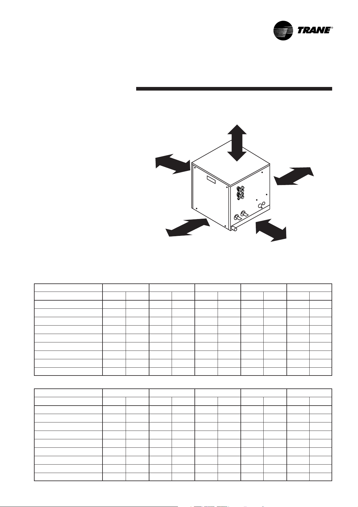
Location and Preparation of Unit
Installation of Condensing Unit at
More than 15 cm
the appropriate places
• The place where is not near the
gas area of potentially hazardous
situations.
More than 10 cm
•Isolated place to avoid noise and
heat disturbing to neighbourhood
• Convenient places for inspection
More than 35 cm
or reparation
Refrigerant Tube Size Selection
To select tube size is necessary to
consider many factors such as:
velocity of refrigerant, number of tube
connector, bended joint and length of
refrigerant tube. Therefore, for quick
selection size of refrigerant tube,
see the detail below:-
Refrigerant tube size for Trane
More than 35 cm
Air-conditioning (size 7,000-60,000 Btu/h)
Figure 1
Domestic
Tubing Length (m) /Tubing size (inch) Minimum 12 m 13 - 18 m 19 - 24 m 25 - 30 m 31 - 36 m
Model Liquid Line Suction Line Liquid Line Suction Line Liquid Line Suction Line Liquid Line Suction Line Liquid Line Suction Line
WTK507 1/4 3/8 1/4 3/8 1/4 3/8 1/4 1/2 1/4 1/2
WTK509 1/4 3/8 1/4 3/8 1/4 3/8 1/4 1/2 1/4 1/2
WTK512 3/8 5/8 3/8 5/8 3/8 5/8 3/8 5/8 3/8 5/8
WTK518 3/8 5/8 3/8 5/8 3/8 5/8 3/8 5/8 3/8 5/8
WTK524 3/8 5/8 3/8 5/8 3/8 3/4 3/8 3/4 3/8 3/4
WTK530 3/8 5/8 3/8 5/8 3/8 3/4 3/8 3/4 3/8 3/4
WTK536 3/8 3/4 3/8 3/4 3/8 3/4 3/8 7/8 3/8 7/8
WTK048 1/2 7/8 1/2 7/8 1/2 7/8 1/2 7/8 1/2 1 1/8
WTK060 1/2 7/8 1/2 7/8 1/2 1 1/8 1/2 1 1/8 1/2 1 1/8
More than 35 cm
Export
Tubing Length (m) /Tubing size (inch) Minimum 12 m 13 - 18 m 19 - 24 m 25 - 30 m 31 - 36 m
Model Liquid Line Suction Line Liquid Line Suction Line Liquid Line Suction Line Liquid Line Suction Line Liquid Line Suction Line
WTK507 1/4 3/8 1/4 3/8 1/4 3/8 1/4 1/2 1/4 1/2
WTK509 1/4 3/8 1/4 3/8 1/4 3/8 1/4 1/2 1/4 1/2
WTK512 1/4 1/2 1/4 1/2 1/4 1/2 1/4 1/2 1/4 1/2
WTK518 1/4 1/2 3/8 5/8 3/8 5/8 3/8 5/8 3/8 5/8
WTK524 3/8 5/8 3/8 5/8 3/8 3/4 3/8 3/4 3/8 3/4
WTK530 3/8 5/8 3/8 5/8 3/8 3/4 3/8 3/4 3/8 3/4
WTK536 3/8 3/4 3/8 3/4 3/8 3/4 3/8 7/8 3/8 7/8
WTK048 3/8 1 1/8 3/8 1 1/8 3/8 1 1/8 3/8 1 1/8 3/8 1 1/8
WTK060 3/8 1 1/8 3/8 1 1/8 3/8 1 1/8 3/8 1 1/8 3/8 1 1/8
WTK-SVN001-EN
5
Page 6

Connection of Refrigerant Tubing
Connection the Unit with Flaring
Procedure
Flaring (If tubing is procured or cut
at the site).
1. Cut the copper tube to the
required length with a tube cutter.
It is recommended to cut approx.
30 cm-50 cm (12” to 20”) longer
than the tubing length you estimate.
2. Hold each tube downward when
cutting, remove burrs at the end of
the copper tube with a tube reamer
or file. This process is important
and should be done carefully to
make a good flare (Figure 2 and
Figure 3).
Copper tubing
Reamer
Figure 2
A good flare should have the
following characteristics:
-Inside surface is glossy and smooth.
- Edge is smooth.
-Tapered sides are of uniform length.
Cautions Before Connecting
Tubes Tightly
1. Be sure to apply a sealing cap or
water-proof tape to prevent dust
or water from getting into the
tubes before they are used.
2. Be sure to apply refrigerant
lubricant to the matching surfaces
of the flare and union before
connecting them together. This is
effective for reducing gas leaks
(Figure 5).
Apply refrigerant lubricant here
4. Tighten the flare nut to the specified
tightening torque with torque
wrench and adjustable wrench
(Figure 7).
5. Repeat the process above for
the remaining line.
Specified tightening torque
Tube diameter Torque
mm inch kg - cm lb - in
6.35 mm (1/4”) dia. 150~200 130~170
9.53 mm (3/8”) dia. 350~400 300~340
12.7 mm (1/2”) dia. 500~550 430~470
15.88 mm (5/8”) dia. 600~650 520~570
19.05 mm (3/4”) dia. 700~750 610~650
22.23 mm (7/8”) dia. 800~850 700~740
28.58 mm (1-1/8”) dia. 900~950 800~825
Before After
Figure 3
When reaming, hold the tube end
downward and be sure that no
copper scraps fall into the tube.
3. Remove the flare nut from the
service valve and be sure to insert
the flare nut onto tube.
4. Make a flare at the end of copper
tube with a flare tool (Figure 4).
Flare nut
Copper
tubing
Flare tool
Figure 5
Connection
3. For proper connection, align the
union tube and flare tube straight
with each other, then screw in the
flare nut lightly at first to obtain a
smooth match (Figure 6).
Union Flare nut
Figure 6
Indoor
unit pipe
To rque wrench
Wrench
(Adjustable)
Tube connection
Flare nut
Figure 7
Figure 4
6
WTK-SVN001-EN
Page 7

Connection Unit
with Brazing Procedure
Connection Unit with Brazing
Procedure
1. Cut the copper tube to the require
length with the tube cutter. It is
recommended to cut approximately
20-30 cm longer than the tube
length you estimate and put in the
straight line while cutting.
2. After cutting, remove burrs at the
end of copper tube with a tube
reamer. Hold the end downward
and be sure that no copper scraps
fall into the tube (Figure 2).
3. There are 2 methods to connect
copper tube
- Use tube connector between
copper tube from fan-coil unit and
copper tube from condensing unit
(Figure 8).
Tube connector
(straight)
- Expand copper tube with the tube
enlarging tool (Figure 9).
Tube enlarging
tool
Tube fixing
Copper
tube
Figure 9
tool
4. Clean copper tube surfaces
both inside and outside before
connection, expansion, or brazing.
5. Insulate the entire gas line.
6. Do not allow uninsulated liquid line
to come in direct contact with bare
gas line.
7. Precautions should be taken to
avoid heat damage to the pressure
tap valve core during brazing. It is
recommended that a wet rag be
wrapped around the valve body.
8. It is recommended to use braze
shield, soak pad in water and place
over suction and liquid lines to
protect unit finish.
9. To braze the copper tube, before
brazing a copper tube to a solder
coupling or a copper tube to an
expanded tube, do not forget to
keep them tight as shown in
figure 10.
Figure 8
Copper tube from
fan coil unit
Copper tube from
condensing unit
Brazing head
COMMET 3
Brazing
wire
Copper tube from
(torch)
connector
(straight)
condensing unit
Figure 10
10. Use a dry nitrogen purge and
brazing alloy without flux when
brazing the field line to the copper
factory connection. Flow dry
nitrogen into either valve pressure
tap port, through the tubing and
out the other port while brazing.
11. Braze using accepted good
brazing techniques.
Tube
WTK-SVN001-EN
7
Page 8

Water Pipe Connection
Installers should prepare the
following equipment:
Should have connected water pipe for
heat exchange. Should have water
pump, cooling tower, pressure gauge,
and other equipments related to the
water pipe connection. Please make
sure that all equipments are according
to the standard (see figure 11).
Water Return Pipe
Connect water return pipe with 3/4
inch pipe connector. Keep them far
away from water tray and add trap
(see figure 12).
Pressure-Reducing/
Water
Return
Water
Supply
Shutoff
Valve
Shutoff
Valve
Balancing Valve
Pressure
Gauge
Plugged
Cleanout
Tee
Water Strainer
Thermometer
Plugged
Cleanout
Tee
Pressure
Gauge
Thermometer
Figure 11
1 inch (25.4 mm) steel pipe and pipe connector
101 mm min
Flow Switch
Union
Union
Flexiible
Connection
To Unit
Flexiible
Connection
Equipment used
1Tee
From Unit
2Plug
70 mm min
3 Steel Elbow
4 140 mm Nipple
1 inch (25.4 mm) PVC pipe or copper pipe and pipe connector
Equipment used
101 mm min
1Tee
1Plug
390o Elbow
70 mm min
1 152 mm Nipple
2 50 mm Nipple
11 NPT to PVC
or copper adapter
Figure 12
8
WTK-SVN001-EN
Page 9

Gas Leakage Inspection
Gas Leakage Inspection
After charging with refrigerant,
it is necessary to check gas leakage.
Inspecting gas leakage should be
done with special precaution. If there
is any leakage that we are unable to
find, afterwards the system would be
damage. For example, if R22
refrigerant loses, cooling coil will be
frozen. There are so many methods to
inspect leakage, but the easiest and
the most economical way is to use
nitrogen gas detector and bubble of
powder detergent per the following
steps:-
•Prepare nitrogen tube with pressure
regulator and pressure gauge or
manifold gauge.
• Open service valve cover (at the
suction side).
• Connect gauge line to the nitrogen
tank, but do not open nitrogen
valve at the nitrogen tank.
• Check out brazing track and all
valves such as flare union.
• Connect the other tails of gauge
line to the service valve (at the
suction side).
•Slowly open nitrogen valve,
let pressure gradually increase until
250 pound/square inches, then put
bubble of powder detergent around
all connected joints, notice any
leakage. Fix the leakage, if any.
If there is no leakage, leave 1-2 hours
to check whether the pressure stays
the same. If the pressure is still
reducing, we need to check leakage
again. Finally, release nitrogen gas
in order to make refrigerant system
to be under vacuum.
Caution
• Do not fully open nitrogen valve to
250 psig because valve may be
damage.
• Do not forget to check the leakage
at the access valve both at the
liquid line and at the suction line.
WTK-SVN001-EN
9
Page 10

Air Evacuation
and Refrigerant Charge
Evacuation
Air and humidity are the enemy of
the air-conditioning system because
humidity will react with R22 refrigerant
and turns into acid, which will corrode
the wire coil and reduce the
compressor oil’s efficiency. Evacuation
is a must to prevent refrigerant system
from air and humidity.
Evacuation Procedure
Connect the middle hose of service
gauge to the vacuum pump, then
connect the hose at the low side to
“service valve” of air-conditioning
at suction line. Connect the hose at
the high side to “service valve” at
liquid line (figure 13).
Fill up R22 refrigerant into the
system
To fill up R22 refrigerant is the final
step of installation. After leakage
check and power wiring, fill up R22
refrigerant to the system.
How to fill up R22 refrigerant
Normally, this needs to be done
immediately after air evacuation per
the following steps (figure 13)
•Fill up the refrigerant via valve at
liquid line until pressure of the
liquid line is around 120-150 psig
(Don’t forget to evacuate air from
liquid line before)
•Turn on evaporator and condensing
unit.
•Fill up the refrigerant into suction
line at the proper quantity while the
unit is working.
• Let machine run for at least 20
minutes. Read pressure from
pressure gauge “at both high and
low side”, and read current
from amp-meter. Usually, suction
line pressure should be around
65-70 psig , and liquid line pressure
should be around 250-275 psig.
If the pressure readings of both liquid
line and suction line are in the range
stated above and electric current
reading is at full load ampere of
condensing unit, it indicates that
refrigerant’s volume is sufficient.
• But if suction pressure is lower than
normal and electric current is far
below full load ampere, it indicates
that refrigerant is inadequate.
You need to add more refrigerant.
• If suction pressure is higher than
normal and electric current is over
the full load ampere, and you notice
some water spray holds on the
compressor, it indicates over cooling
system. You need to release some
refrigerant.
Remark: When the interconnecting
line is longer than 7.5 m, additional
charging is necessary. For the additional
amount, follow the table belows.
10
Service
hoses
Liquid
line
Suction
line
Electrical
connection
Figure 13
Liquid
pressure
Suction
pressure
Vacuum pump
R22
Piping Per each additional
size meter of
interconnecting line
Liquid-Suction grams/meter
1/4é-3/8
1/4é-1/2
3/8é-5/8
3/8é-3/4
3/8é-11/
1/2é-7/8
é
é
é
é
é
8
é
23 grams/meter
26 grams/meter
59 grams/meter
60 grams/meter
68 grams/meter
117 grams/meter
WTK-SVN001-EN
Page 11

Wiring and System Inspection before
Test Run and Condenser Cleaning
Electric wire and ground wire must
comply with each country’s or regional’s
regulation.
1. Wiring
Importance
- Check the unit nameplate for
electrical rating. Make sure that
the wiring is according to local
codes and wiring system diagram.
-A separate power supply
disconnect and a circuit breaker
for overcurrent protection should
be provided in the external power
supply line.
-Always connect ground wire to
condensing unit every time to
prevent an electric shock in case
of an electric leakage.
-Electric wires shall not contact
to refrigerant pipes, compressor,
motor and the other moving parts.
- Manufacturer assumes no liability
for the problems caused by
unauthorized change in the
internal wiring.
- Should tighten up wire connection.
-Electric conductor parts must be
copper only.
To inspect system before test run.
After finished installing
air-conditioning, all system shall be
inspected before starting.
• Check that all brazings are correctly
made.
• Check that units are correctly
installed and there are no other
tools near or on top of the unit.
• Check the tubing and connections
for leak.
• Check that unit has a proper
ground wiring.
• Check for proper voltage and fuse
size.
• Check electrical wire size used is
as specified.
• Check all field wiring for tight
connection.
• Make sure that electrical wires
inside the unit do not contact to
refrigerant pipes.
•Turn on the unit, check the system
carefully.
Condenser Cleaning
After air-conditioning works for
a while, it may cause scales at the
surface of pipe in the condensing unit,
which may cause by cooling water
or rust inside cooling tower. Installer
can notice from the reduction of water
velocity, or the reduction of difference
of water temperature in and out,
or condensing temperature is higher
than normal.
Therefore, to maintain efficiency of
condenser, installer must clean up the
pipe’s inside surface of condenser to
prevent scales.
To clean up condenser with chemical
To clean up condenser with chemical
is one of the methods to wipe out
scales. To select proper chemical,
installer need to consult the water
treatment expert.
2. Electric Wire Connection
- See wiring diagram on page 12
-Slipover electric wire at the end
-After connect electric wire,
check whether all screws are
firmly tightened
The electric wire connection between
outdoor and indoor unit should be
according to the wiring diagram.
WTK-SVN001-EN
11
Page 12

Wiring Diagram
POWER SUPPLY 220-240V/1ph/50Hz, 200-240V/1ph/60Hz
POWER CIRCUIT
MS-1
RD
BL
L
CR
R
CPR
S
N
MS-2
BLK
C
CONTROL CIRCUIT FOR MODEL WITHOUT HPCO AND LPCO
*2TC
C1
FROM INDOOR UNIT
200-240VAC/1ph/50,60Hz
MS
CONTROL CIRCUIT FOR MODEL WITH HPCO AND LPCO
BYPASS LPCO WHEN UNIT START, BYPASS TIME PERIOD CAN BE SETTING 0-4.5 MINS
1TC
(FOR BY PART LPCO WHEN UNIT START)
BLK
1R-7
1R
1R-8
1R
LPCO
C1
HPCO
1R-1
1R-5
1R-6
G
C2
2R-7
*2TC
2R
2R-8
MS
C2
12
2R
2R-1
2R-2
2R-5
2R-6
FROM INDOOR UNIT
220-240V/1ph/50,60Hz
COLOR CODE
BL BLUE
BLK BLACK
RD RED
* 2TC AVAILABLE IN OPTIONAL MODEL
** APPLY FOR DOUBLE POLE CONTACTOR ONLY
(FOR SINGLE POLE CONTACTOR,CONNECT ELECTRIC
LINE FROM COMPR-C DIRECT TO TERMINAL-N)
NOTES:
1. LOW VOLTAGE WIRING TO BE
18 AWG MINIMUM CONDUCTOR.
2. POWER WIRING AND GROUNDING OF
EQUIPMENT MUST COMPLY WITH
LOCAL CODES.
3. USE COPPER CONDUCTOR ONLY.
LEGEND
CPR COMPRESSOR
MS COMPRESSOR MOTOR CONTACTOR
HPCO HIGH PRESSURE CUT-OUT
LPCO LOW PRESSURE CUT-OUT
TC TIME-DELAYED CONTACT 3 MINUTES
1R LOCK OUT CIRCUIT RELAY
2R LOW PRESSURE SENSOR BYPASS RELAY
TERMINAL
COIL
TERMINAL BOARD BY OTHER
TERMINAL BOARD BY FACTORY
FIELD WIRING
FACTORY WIRING
RELAY CONTACT NORMALLY OPEN
CAPACITOR
LOW PRESSURE SENSING SWITCH
HIGH PRESSURE SENSING SWITCH
WTK-SVN001-EN
Page 13

Wiring Diagram
WTK048-060
POWER SUPPLY 380-415V/3ph/50Hz ,460V/3ph/60Hz
G L1
BLK
MS-1
BLK
LPCO HPCO
C1
LEGEND
CPR COMPRESSOR
MS COMPRESSOR MOTOR CONTACTOR
HPCO HIGH PRESSURE CUT-OUT
LPCO LOW PRESSURE CUT-OUT
TC TIME-DELAYED CONTACT 3 MINUTES
TERMINAL
COIL
TERMINAL BOARD BY OTHER
TERMINAL BOARD BY FACTORY
FIELD WIRING
FACTORY WIRING
RELAY CONTACT NORMALLY OPEN
CAPACITOR
LOW PRESSURE SENSING SWITCH
HIGH PRESSURE SENSING SWITCH
1R
FROM INDOOR UNIT 220V/1ph/50Hz
L2 L3
MS-2
RD
2
CPR
1
87
1R
MS-3
3
*TC
651
*AVAILABLE IN OPTIONAL MODEL
NOTES:
1. LOW VOLTAGE WIRING TO BE
18 AWG MINIMUM CONDUCTOR.
2. POWER WIRING AND GROUNDING OF
EQUIPMENT MUST COMPLY WITH
LOCAL CODES.
3. USE COPPER CONDUCTOR ONLY.
YL
MS
COLOR CODE
YL YELLOW
BLK BLACK
RD RED
C2
WTK-SVN001-EN
13
Page 14

Dimensional Data
WTK507-518
400
400
WATER OUTLET
50.8
50.8
302.2
232.2
Ø3/4 FTP DRAIN PIPE
WATER INLET
LIQUID LINE
SUCTION LINE
358.2
293.2
POWER SUPPLY
Ø3/4 In.
53.543
69
DOMESTIC
MODEL
REFRIGERANT CONNECTION SIZE (In.) WATER
LIQUID SUCTION CONNECTION SIZE (In.)
WTK507-509 1/4 3/8 3/4
WTK512-518 3/8 5/8 3/4
400
14
EXPORT
MODEL
REFRIGERANT CONNECTION SIZE (In.) WATER
LIQUID SUCTION CONNECTION SIZE (In.)
WTK507-509 1/4 3/8 3/4
WTK512-518 1/4 1/2 3/4
WTK-SVN001-EN
Page 15

109
22
179
49
Dimensional Data
WTK524-060
500
400
WATER INLET
LIQUID LINE
SUCTION LINE
477.6
179
WATER OUTLET
432.6
Ø3/4 FTP DRAIN PIPE
DOMESTIC
EXPORT
POWER SUPPLY
Ø5/8 In.
477.6
412.6
43
51.1
200.4
MODEL REFRIGERANT CONNECTION SIZE (In.) WATER
LIQUID SUCTION CONNECTION SIZE (In.)
WTK524-530 3/8 5/8 3/4
WTK536 3/8 3/4 3/4
WTK048-060 1/2 7/8 7/8
MODEL REFRIGERANT CONNECTION SIZE (In.) WATER
LIQUID SUCTION CONNECTION SIZE (In.)
WTK524-530 3/8 5/8 3/4
WTK536 3/8 3/4 3/4
WTK048-060 3/8 1-1/8 7/8
520
WTK-SVN001-EN
15
Page 16

Trane Thailand
7th Floor, Ploenchit Center Building
2 Sukhumvit Road, Klongtoey
Bangkok 10110
Amair Limited
35 Mu 8, Poochaosamingprai Road
Samrong Tai, Samutprakarn 10130
http://www.trane.com
An American Standard Company
Literature Order Number
Supersedes
Stocking Location Bangkok, Thailand
WTK-SVN001-EN0404
WTK-SVN001-EN0303
∫√‘…—∑ ·Õ¡·Õ√å ®”°—¥ 35 À¡Ÿà 8 ∂.ªŸÉ‡®â“¡‘ßæ√“¬ µ.”‚√ß„µâ Õ.æ√–ª√–·¥ß ®.¡ÿ∑√ª√“°“√ 10130
Since The Trane Company has a policy of continuous product and product data improvement,
it reserves the right to change design and specifications without notice.
 Loading...