

Page 1
Accessories
Thermostats/Sensors
WSHP-PRC003-EN
R
180
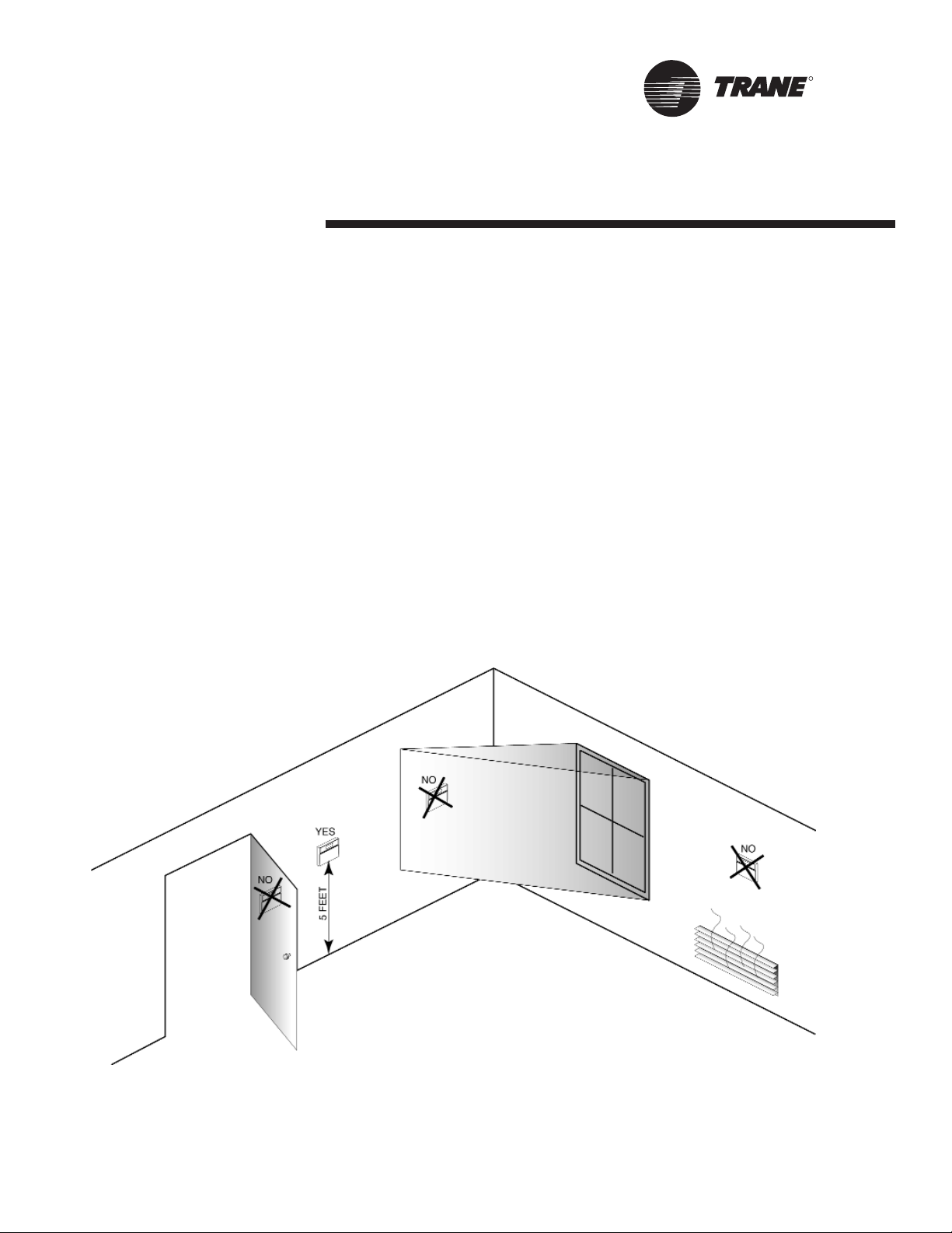
Thermostat/Sensor Location
Location of the thermostat or zone sensor is an important element of effective
room control and comfort.
The best location is typically on a wall,
remote from the HVAC unit. Readings at
this location assure that the desired setpoint is achieved across the space, not
just near the unit itself. It may be necessary to subdivide the zone to ensure
adequate control and comfort.
See Figure 36 for detailed areas where
the thermostat or zone sensor should
and should not be mounted. These
include:
• Near drafts or “dead spots”
(Behind doors or corners)
• Near hot or cold air ducts
• Near radiant heat (appliances,
windows, etc.)
• Near concealed pips or chimneys
• On outside walls or other
non-conditioned surfaces.
• In air flows from adjacent zones or
other units.
Figure 36: Proper thermostat and sensor location.
Page 2
R
Accessories
Thermostats/Sensors
WSHP-PRC003-EN
181
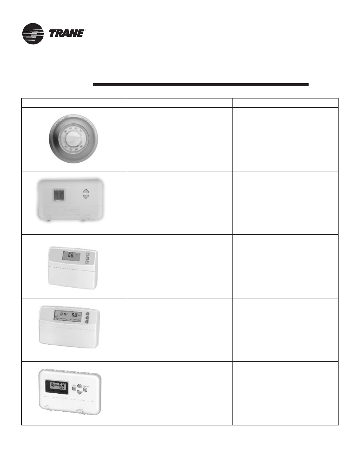
Thermostat/Sensor Part Number Description
X13510309010 - thermostat
X13530069010 - subbase
(006 - 060 models only)
Mercury Thermostat
• 0-stage heat/1-stage cool manual
changeover with COOL-OFF
• Non Programmable
• Fan switching includes
• FAN ON-AUTO
X13511039010
(006 - 060 models only)
Manual Changeover Digital Stat
• 2-stage heat/1-stage cool
• System switching includes HEAT-OFFCOOL
• Fan switching includes AUTO-ON
• Non programmable
• Auto compatible with F
O
or C
O
temperature readings
X13511041010
Auto/Manual Changeover Digital Stat
• 1-stage heat/1-stage cool
• System switching includes HEAT-OFFCOOL-AUTO
• Fan switching includes ON-AUTO
• Non programmable
• Auto compatible with F
O
or C
O
temperature readings
X13511042010
Auto/Manual Changeover Digital Stat
• 3-stage heat/2-stage cool
• System switching includes HEAT-OFFCOOL-AUTO
• Fan switching includes ON-AUTO
• 7-day programmable
• Adjustable 1 to 15-degree night setback
• Auto compatible with F
O
or C
O
temperature readings
X13511043010
Manual Changeover Digital Stat
• 2-stage heat/1-stage cool
• System switching includes HEAT-OFFCOOL
• Fan switching includes ON-AUTO
• 5-day programmable
• Adjustable 1 to 15-degree night setback
• Auto compatible with F
O
or C
O
temperature readings
Page 3
Accessories
Thermostats/Sensors
WSHP-PRC003-EN
R
182
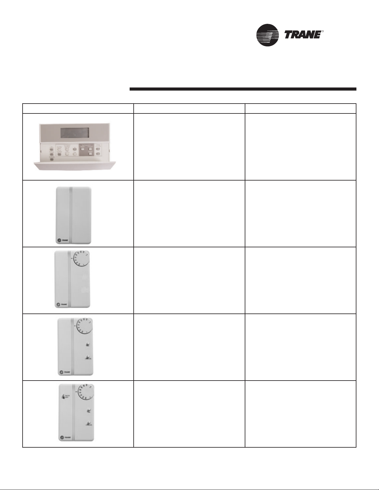
Thermostat/Sensor Part Number Description
X13511091010 - thermostat
X13511092010 - subbase
(072 - 150/240 models only)
Digital Thermsostat
• 3-stage heat/2-stage cool with AUTOEM HEAT-HEAT-OFF-COOL
• Non Programmable
• Fan switching includes FAN ON-AUTO
• 2 LEDs
• Auto compatible with F
O
or C
O
temperature readings
X13510628010
Zone Sensor
• Tracer ZN510 and ZN524 compatible
• Internal setpoint adjustment wheel
• Communication Jack
X13510606010
Zone Sensor
• Tracer ZN510 and ZN524 compatible
• External setpoint adjustment wheel
• Communication Jack
X13510606020
Zone Sensor
• Tracer ZN510 and ZN524 compatible
• External setpoint adjustment wheel
• Communication Jack
• ON and CANCEL buttons
X13510635010
Zone Sensor
• Tracer ZN510 and ZN524 compatible
• External setpoint adjustment wheel
• Communication Jack
• ON and CANCEL buttons
• Fan switch AUTO-OFF
Page 4

R
Accessories
WSHP-PRC003-EN
183
Pump Module
The pump module and hose kit make a
complete self-contained pumping package for distributed pumping systems.
These kits contain all the necessary
components for the installation, operation and maintenance of the water circuit of a closed loop geothermal application. Standard pump module features
include insulated Grundfos pumps,
insulated cabinet, bronze or cast iron
pump, and 3-way brass valves. The
module is factory piped, wired and
mounted. See Figure 40 for pump module assembly. Literature number
WSHPC-IN-5 (72-9006-03) will provide
electrical and dimensional requirements for the PMCA and PMBA products.
Figure 37: Pump module
Pump Module Hose Kit
The pump module hose kit consists of
two brass, 3/4 or 1-inch male pipe
thread (MPT) -by-barb fittings; two
brass 90 degree 1-inch, MPT-by-barb
elbows with pressure/temperature
ports; and 10 feet of rubber hose with 4
hose clamps. The pump module hose
kit is available separately from the
pump module.
Figure 38: Pump module hose kit
Water Regulating Valve
Assembly
The water regulating valve assembly
consists of a direct acting valve and a
reverse acting valve installed on the
water-out side of the unit. The valve
connection sizes shall range from 1/2"
to 1 1/2" FPT. The direct acting valve
opens in response to an increase in discharge pressure during the cooling
cycle. The reverse acting valve opens in
response to a decrease in suction pressure during the heating cycle. Water
regulating valves should be used where
low flow and low or high fluid temperature conditions could occur. See page
29 of this manual for application information.This option is beneficial with
open loop systems, but not necessary.
Figure 39: Water regulating valve
Motorized Water Valve
The motorized water valve is installed
on the return line of the water loop system between the loop and the loop’s
pump module. This isolation device is
less expensive and a very effective
alternative to the water regulating
valve.
When the compressor begins running,
the valve will open, allowing water to
flow through the unit. As the compressor shuts down, the valve slowly closes
off. The main purpose of the motorized
valve is to shut-off the flow of water
through the unit when the unit is off,
thus reducing water consumption. The
motorized valve is fast opening to prevent compressor trip-out, and slow
closing to prevent water hammer.
Figure 40: Motorized water valve
Page 5

Accessories
WSHP-PRC003-EN
R
184
Ducted Panel
The return-air arrangement may be
easily converted from a free return-air
system, to a ducted return-air system
with the addition of a return-air side
panel. By replacing the filter racks with
the return-air panel, a complete seal
from the duct to the unit is possible.
The 1-1/2"(38mm) duct flange facilitates ease of field connection to the
mechanical system. This accessory is
typically used when the return-air filter
is placed in a built-in ceiling grille, or
placed within a field provided filter rack
assembly.
Figure 41: Return-air duct panel
Hose Kits
Trane provides three hose kit selections for equipment balancing.
• Ball valve flow control (manual)
• Circuit setter flow control (manual)
• Automatic flow control (automatic)
Each selection provides some accuracy in equipment balancing. Range of accuracy
consist of ±25% for the ball valve method, ±20% for the circuit setter method, and
±10% for the automatic flow control method.
Utilizing the ball valve method, the pressure/temperature measurement on the
leaving and entering side of the heat pump is measured within the water piping.
The ball valve is then throttled to change the amount of flow to the unit to reach
the desired temperature or pressure differential.
The circuit setter method combines both the readout and the adjustment feature in
one device. In order to determine flow rate, the user must record both handle position, and differential pressure drop. Then, the user must consult a chart containing
both pieces of information to make the necessary adjustments to the circuit setter.
For automatic system balancing of a water-source heat pump, the Mesurflo® self
balancing kit provides a constant flow rate over the pressure differential rage of 2
to 80 psid. As system pressure changes (through further addition of heat pumps,
for example) each individual flow control valve will automatically adjust to the new
system conditions. In variable water volume applications, a self balancing hose kit
can provide continuous balancing because of its ability to automatically adjust to
the varying system conditions. For more information pertaining to the automatic
balancing hose kits, see literature
documentation WSHP-SLB005-EN.
Figure 42: System balancing hose kits.
Unit
SizeA(in/mm)B(in/mm)
Model
Number
006-
015
17-1/2
(445)
13
(330)
4474 1133 0100
018-
030
20-1/2
(521)
15
(381)
4474 1134 0100
036-
042
22-1/2
(572)
17
(432)
4474 1135 0100
048-
060
26-1/2
(673)
19
(483)
4474 1136 0100
150,
180
* * 4475 2119 0100
240 * * 4475 2121 0100
Page 6

R
Mechanical Specifications
WSHP-PRC003-EN
185
General
Equipment shall be completely assembled, piped, internally wired, fully
charged with HCFC-22 and test operated at the factory. Filters, thermostat
field interface terminal strip, and all
safety controls are furnished and factory installed.
The system water inlet and outlet connections shall be female NPT composed of either a copper or a bronze
option.
The 5-ton and below equipment shall
contain ETL, CETL and ISO-ARI 13256-1
listings and labels prior to leaving the
factory. Larger units shall be rated in
accordance with ISO-ARI 13256-1.
Service and caution area labels shall
also be placed on the unit in their
appropriate locations.
The 6 through 10-ton equipment shall
contain ETL, CETL and ISO-ARI 13256-1
listings and labels prior to leaving the
factory. Larger units shall be rated in
accordance with ISO-ARI 13256-1.
Service and caution area labels shall
also be placed on the unit in their
appropriate locations.
Cabinet
Unit casing shall be constructed of zinc
coated, heavy gauge, galvanized steel.
Service to the refrigerant and controls
shall be provided through a single
access panel at the front of the equipment. Access to the refrigerant and
controls for the larger units shall be
provided through the front and side
access panels.
All panels shall be insulated with
1/2-inch (13mm) thick dual density
bonded glass fiber. The exposed side is
a high density erosion proof material
suitable for use in air streams up to
3600 feet per minute (FPM). The insulation meets the erosion requirements of
UL 181. It has a flame spread of less
than 25 and a smoke developed classification of less than 50 per ASTM E-84
and UL 723.
Access for inspection and cleaning of
the unit drain pan, coils and fan section
shall be provided. The unit shall be
installed for proper access.
Filters
One inch or two inch, throwaway
filters shall be standard and factory
installed. The filters shall have an average resistance of 76-percent and dust
holding capacity of 26-grams per
square foot.
Sound Attenuation
Sound attenuation shall be applied as a
standard feature in the product design.
The sound reduction package shall
include a compressor discharge muffler,
vibration isolation to the compressor
and water-to-refrigerant coil, unit base
stiffeners, insulated metal compressor
enclosure, and a second stage of vibration isolation to the compressor and
water-to-refrigerant base pan.
All units shall be tested and rated in
accordance with ARI 260.
Compressors
The unit shall contain a high efficiency
rotary, reciprocating, or scroll compressor. External vibration isolation shall be
provided by rubber mounting devices
located underneath the mounting base
of the compressor. A second isolation
of the refrigeration assembly shall be
supported under the compressor
mounting base.
Internal thermal overload protection
shall be provided. Protection against
excessive discharge pressure shall be
provided by means of a high pressure
switch. A loss of charge shall be provided by a low pressure safety.
Refrigerant Tubing
The refrigerant tubing shall be of 99%
pure copper. This system shall be free
from contaminants and conditions such
as drilling fragments, dirt and oil. All
refrigerant and water lines shall be
insulated with an elastomeric insulation
that has a 3/8-inch thick wall in the airside section of the unit.
Refrigerant Circuits
The refrigerant circuit shall contained a
thermal expansion device. Service pressure ports shall be factory supplied on
the high and low pressure sides for
easy refrigerant pressure or temperature testing.
Air-to-Refrigerant Coil
Internally finned, 3/8-inch copper tubes
mechanically bonded to a configured
aluminum plate fin shall be standard.
Coils shall be leak tested at the factory
to ensure the pressure integrity. The
coil shall be leak tested to 200 psig and
pressure tested to 450 psig.
The tubes are to be completely evacuated of air and correctly charged with
proper volume of refrigerant prior to
shipment.The refrigerant coil distributor
assembly shall be of orifice style with
round copper distributor tubes. The
tubes shall be sized consistently with
the capacity of the coil. Suction header
shall be fabricated from rounded copper pipe.
A thermostatic expansion valve shall be
factory selected and installed for a wide
range of control.
Drain Pan
The condensate pan shall be constructed of corrosion resistant material and
insulated to prevent sweating. The bottom of the drain pan shall be sloped on
two planes which pitches the condensate to the drain connection. The drain
pan shall be flame rated per UL945V-B.
Page 7

Mechanical
Specifications
WSHP-PRC003-EN
R
186
When the unit is installed and trapped
per the manufacturers installation manual, and local city specifications, the
drain pan shall be designed to leave
puddles no more than 2-inch in diameter, no more than 1/8-inch deep, no
longer than 3-minutes following Step 3
of the following test:
1. Temporarily plug the drain pan.
2. Fill the drain pan with 1/2-inch of
water or the maximum allowed by
the drain pan depth, whichever is
smaller.
3. Remove the temporary plug.
Water-to-Refrigerant Heat
Exchanger
The water-to-refrigerant heat exchanger
shall be of a high quality co-axial coil
for maximum heat transfer. The copper
or optional cupro-nickel coil shall be
deeply fluted to enhance heat transfer
and minimize fouling and scaling. The
coil shall have a working pressure of
400 psig on both the refrigerant and
water sides. The factory shall provide
rubber isolation to the heat exchanging
device to enhance sound attenuation.
Indoor Fan
The blower shall be a forward-curved
style wheel with four speed combinations, or nine blower motor/sheave
combinations available.
All direct drive motors shall have
sealed bearings that do not require
field lubrication.
Options of the blower motor/fan packages shall be selected and wired from
the factory to match performance criteria suggested in the performance section. The motor shall contain a quick
disconnect plug for service, convertibility and safety precautions.
The fan(s) shall be placed in a draw-
through configuration. They shall be
constructed of corrosion resistant galvanized material.
Electrical
The unit control box shall contain all
necessary devices to allow heating and
cooling operation to occur from a
remote wall thermostat. These devices
shall be as follows:
• 24 VAC energy limiting class II
50 VA (minimum) transformer
• 24 VAC blower motor relay
24 VAC compressor contactor for
compressor control
• Field thermostat connections shall
be provided for ease of hook-up to
a terminal strip located in the unit’s
control box
• Lockout relay which controls
cycling of the compressor shall be
provided to protect the compressor
during adverse operating conditions. The device may be reset by
interrupting power to the 24 VAC
control circuit. Reset may be done
either at a remote thermostat or
through a momentary main power
interruption
• A high pressure switch shall protect
the compressor against operation
at refrigerant system pressures
exceeding 395 psig.
• The low-water temperature switch
or sensor shall prevent the
compressor operation with leaving
water temperatures below
20 F/-6 C.
• Factory installed wire harness shall
be available for the Basic, Deluxe,
ZN510 and ZN524 control packages.
Nameplate information shall be provided for the application of either time-
delay fuses or HACR circuit breakers for
branch circuit protection from the primary source of power.
Basic Controls (option)
The basic control package shall contain
a low and high pressure switch along
with a compressor lockout relay for
control assistance. High voltage power
connections shall be made at the equipments contactor. An optional condensate overflow detection device shall be
made available with this control package. Each device shall be factory
mounted, wired, and tested in the
equipment.
Deluxe Controls (option)
The deluxe control package shall provide a 75 VA transformer with circuit
breaker. The controller shall include a
lockout relay, anti-short cycle compressor protection, random start delay,
brown-out protection, low pressure
time delay, compressor delay on start
and an open relay for night setback or
pump request.
Optional wiring from the factory for
night setback, condensate overflow, hot
gas reheat, electric heat, and compressor enable shall also be provided. Three
LEDs (light emitting diodes) shall also
be included for diagnostics of the
equipment.
Tracer ZN510 or ZN524
Controller (option)
This system shall utilize factory furnished and mounted DDC controls for
operation of up to 120 units on a Comm
5 (LonMark) link. The Tracer ZN510 control package shall include a 75 VA transformer. The controller shall provide random start delay, heating/cooling status,
occupied/unoccupied mode, fan status
and filter maintenance options.
Optional wiring from the factory for
condensate overflow shall be available.
Page 8

R
Mechanical
Specifications
WSHP-PRC003-EN
187
Three LEDs (light emitting diodes) shall
be included for diagnostics of the
equipment.
The ZN510 shall be capable of a standalone application, or as applied to a full
building automation installation.
Tracer ZN524 Controller (option)
The ZN524 controller shall utilize factory furnished and mounted DDC controls
for operation of up to 120 units on a
Comm 5 (LonMark) link. The Tracer
ZN524 control package shall include a
75 VA (minimum) transformer. The controller shall provide random start delay,
heating/cooling status, occupied/unoccupied mode, fan status and filter maintenance options. Optional wiring from
the factory for condensate overflow
shall be available. Three LEDs (light
emitting diodes) shall be included for
diagnostics of the equipment.
The ZN524 shall be capable of a standalone application, or as applied to a full
building automation installation.
With this controller, the unit shall be
capable of a hot gas reheat (for dehumidification), boilerless control for electric heat, waterside economizing, and
support of variable speed pump control
applications.
Orifice Ring
Removal of the motor and fan wheel
for the 1/2 through 5-ton units shall be
made with the assistance of a factory
provided orifice ring device. This device
shall attach the wheel and motor to the
fan housing in one assembly providing
single side service access.
Water Regulating Valve
Assembly
(option)
The water regulating valve assembly
shall consist of a direct acting valve and
a reverse acting valve. The direct acting
valve shall open in response to an
increase in discharge pressure during
the cooling cycle. The reverse acting
valve shall open in response to a
decrease in suction pressure during the
heating cycle. Water regulating valves
shall be used where low flow, or low or
high fluid temperature conditions exist.
This accessory shall be used with openloop systems.
Economizing Coil (GEH option)
The waterside economizing package
shall be an external unit accessory prepiped and pre-wired ready for turn-key
installation to the unit. The economizing
coil shall be designed to perform with
the WSHP at unit measured flow rate of
80.6 F DB/66.2 F WB with 45 F EWT.
All hydronic coils shall be of 5/8" copper and aluminum plate fin combination. All coils shall be proof and leak
tested from the manufacturer. The proof
test shall be performed at 1.5 times the
maximum operating pressure and the
leak test at the maximum operating
pressure.
A dual sloped non corrosive drain pan
shall be easily accessible and cleanable
for the hydronic economizing coil.
An electronic two-position, 3-way valve
shall meter water flow to the economizing coil during the economizing mode.
It shall be factory set to energize the
economizing mode at 55 F, while simultaneously halting mechanical operation
of the compressor.
Hanging brackets with rubber isolation
shall be provided for the horizontal version of the economizing coil option. The
bracket design shall be the same
throughout the equipment.
Electric Heat (option)
Boilerless control electric heat shall be
factory wired and tested. It shall be
composed of a nichrome open wire coil
designed for 2-kW per unit ton. The
design consist of a single stage of electric heat used as a primary heating
source when compressor lockout has
occurred due to the entering water temperature falling below 55 F with an
adjustable range between 25 F to 60 F.
All power connections to the electric
heat shall be made in the equipment’s
control box.
Hot Gas Reheat (option)
Dehumidification shall be provided
through a hot gas reheat option. The
coil shall consist of 3/8"/1/2" copper
tubes mechanically expanded into
evenly spaced aluminum fins. All coils
shall be proof and leak tested. The
proof test must be performed at 1.5
time the maximum operating pressure
and the leak test performed at the maximum operating pressure.
Ball Valves (option)
Ball valves shall be field installed
between the unit and the supply and
return lines of the loop to stop water
flow to the unit in a maintenance or
service situation.
Motorized Water Valve (option)
When extreme fluid temperature conditions do not exist with an open loop
system, a motorized water valve shall
be applied to each water-source heat
pump. The motorized valve shall stop
flow to the unit, causing pressures to
rise. This rise in pressure will halt pump
operation to provide greater energy
savings of the entire system.
Pump Module (option)
The pump module shall be a complete
self contained pumping package for an
earth-coupled heat pump system.
The module shall consist of a single,
1/6-HP bronze pump, and a brass 3-way
shut-off valve. These kits shall contain
the necessary components for the
installation, operation, and maintenance of the water circuit of a closedloop distributed pumping application.
Page 9

Mechanical
Specifications
WSHP-PRC003-EN
R
188
Hoses (option)
Hoses shall consist of a stainless steel
outer braid with an inner core of tube
made of a nontoxic synthetic polymer
material. The hoses shall be suitable for
water temperatures ranging between 33
F and 211 F without the use of glycol.
Automatic Flow Devices (option)
The automatic flow kit shall contain a
Hays Mesurflo® automatic flow control
valve, two ball valves, two flexible
hoses, a high flow Y-strainer, and may
include a strainer blow-down and various other accessories.
The automatic flow control valve shall
be factory set to a rated flow, and shall
automatically control the flow to within
10% of the rated value over a 40 to 1
differential pressure, operating range (2
to 80 PSID). Operational temperature
shall be rated from fluid freezing, to
225-degrees F. The valve body shall be
constructed from hot forged brass UNS
C37700 per ASTM B-283 latest revision.
For more information pertaining to the
automatic balancing hose kits, see literature documentation
WSHP-SLB005-EN.
Page 10

Literature Order Number WSHP-PRC003-EN
Date PL-RF-WSHP-PRC003-05-04
Supercedes Update
Stocking Location Electronic Only
Since the Trane Company has a policy of continuous product and product data
improvement, it reserves the right to change design and specifications without
notice.
The Trane Company
An American Standard Company
www.trane.com
For more information, contact
your local district office or
e-mail us at comfort@trane.com
 Loading...