

Page 1
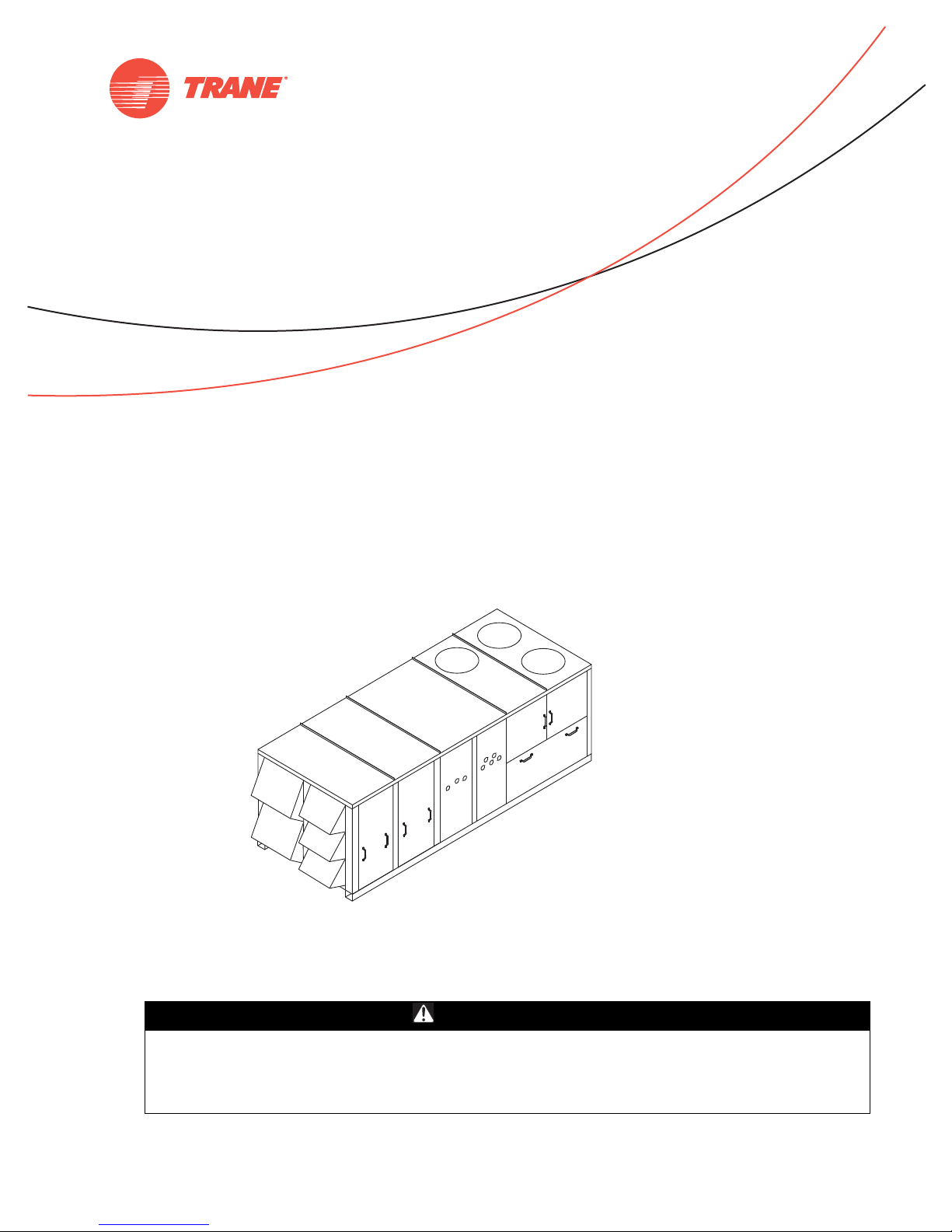
Installation, Operation,
and Maintenance
Voyager™ Commercial
27.5 to 50 Ton 60 Hz
22.9 to 41.7 Ton 50 Hz
CV, VAV, or SZ VAV Rooftop Air Conditioners
with ReliaTel™ Controls, R-410A Refrigerant
Model Numbers
“B” and later design sequence
TC*, TE*, YC*330B, 360B, 420B, 480B, 600B (60 Hz/3 phase)
TC*, TE*, YC*275B, 305B, 350B, 400B, 500B (50 Hz/3 phase)
Only qualified personnel should install and service the equipment. The installation, starting up, and
servicing of heating, ventilating, and air-conditioning equipment can be hazardous and requires specific
knowledge and training. Improperly installed, adjusted or altered equipment by an unqualified person could
result in death or serious injury. When working on the equipment, observe all precautions in the literature
and on the tags, stickers, and labels that are attached to the equipment.
August 2012 RT-SVX34F-EN
SAFETY WARNING
Page 2
Warnings, Cautions and Notices
Warnings, Cautions and Notices. Note that warnings,
cautions and notices appear at appropriate intervals
throughout this manual. Warnings are provided to alert
installing contractors to potential hazards that could result
in personal injury or death. Cautions are designed to alert
personnel to hazardous situations that could result in
personal injury, while notices indicate a situation that could
result in equipment or property-damage-only accidents.
Your personal safety and the proper operation of this
machine depend upon the strict observance of these
precautions.
ATT EN TI ON : Warnings, Cautions and Notices appear at
appropriate sections throughout this literature. Read these
carefully:
WARNING
CAUTIONs
NOTICE:
Indicates a potentially hazardous
situation which, if not avoided, could
result in death or serious injury.
Indicates a potentially hazardous
situation which, if not avoided, could
result in minor or moderate injury. It
could also be used to alert against
unsafe practices.
Indicates a situation that could result in
equipment or property-damage only
Personal Protective Equipment (PPE)
Required!
Installing/servicing this unit could result in exposure to
electrical, mechanical and chemical hazards.
• Before installing/servicing this unit, technicians
MUST put on all Personal Protective Equipment (PPE)
recommended for the work being undertaken.
ALWAYS refer to appropriate MSDS sheets and OSHA
guidelines for proper PPE.
• When working with or around hazardous chemicals,
ALWAYS refer to the appropriate MSDS sheets and
OSHA guidelines for information on allowable
personal exposure levels, proper respiratory
protection and handling recommendations.
• If there is a risk of arc or flash, technicians MUST put
on all Personal Protective Equipment (PPE) in
accordance with NFPA 70E or other country-specific
requirements for arc flash protection, PRIOR to
servicing the unit.
Failure to follow recommendations could result in death
or serious injury.
WARNI NG
Important
Environmental Concerns!
Scientific research has shown that certain man-made
chemicals can affect the earth’s naturally occurring
stratospheric ozone layer when released to the
atmosphere. In particular, several of the identified
chemicals that may affect the ozone layer are refrigerants
that contain Chlorine, Fluorine and Carbon (CFCs) and
those containing Hydrogen, Chlorine, Fluorine and Carbon
(HCFCs). Not all refrigerants containing these compounds
have the same potential impact to the environment. Trane
advocates the responsible handling of all refrigerantsincluding industry replacements for CFCs such as HCFCs
and HFCs.
Responsible Refrigerant Practices!
Trane believes that responsible refrigerant practices are
important to the environment, our customers, and the air
conditioning industry. All technicians who handle
refrigerants must be certified. The Federal Clean Air Act
(Section 608) sets forth the requirements for handling,
reclaiming, recovering and recycling of certain refrigerants
and the equipment that is used in these service procedures.
In addition, some states or municipalities may have
additional requirements that must also be adhered to for
responsible management of refrigerants. Know the
applicable laws and follow them.
WARNI NG
Proper Field Wiring and Grounding
Required!
All field wiring MUST be performed by qualified
personnel. Improperly installed and grounded field
wiring poses FIRE and ELECTROCUTION hazards. To
avoid these hazards, you MUST follow requirements for
field wiring installation and grounding as described in
NEC and your local/state electrical codes. Failure to
follow code could result in death or serious injury.
Overview of Manual
One copy of the appropriate service literature ships inside
the control panel of each unit. The procedures discussed in
this manual should only be performed by qualified,
experienced HVAC technicians.
Note: Do not release refrigerant to the atmosphere! If
adding or removing refrigerant is required, the
service technician must comply with all federal,
state, and local laws.
This booklet describes the proper installation, startup,
operation, and maintenance procedures for TC_, TE_, and
YC_22.9 to 50 Ton CV (Constant Volume), VAV (Variable Air
Volume), and SZ VAV (Single Zone Variable Air Volume)
applications. Refer to the table of contents for a listing of
specific topics. Refer to “Diagnostics,” p. 104 for
troubleshooting information.
© 2012 Trane All rights reserved RT-SVX34F-EN
Page 3
By carefully reviewing the information within this manual
and following the instructions, the risk of improper
operation and/or component damage will be minimized.
It is important that periodic maintenance be performed to
help assure trouble free operation. A maintenance
schedule is provided at the end of this manual. Should
equipment failure occur, contact a qualified service
organization with qualified, experienced HVAC technicians
to properly diagnose and repair this equipment.
Revision History
RT-SVX34F-EN (10 August 2012)
• Motors with Internal Shaft Grounding Ring
• Updated Model Number Description, Installation
Electrical, Unit Wiring Diagrams
Warnings, Cautions and Notices
60 Hz units with standard options are certified by
Underwriters Laboratory.
RT-SVX34F-EN 3
Page 4

Table of Contents
Model Number Description . . . . . . . . . . . . . . . 7
60 Hz Description . . . . . . . . . . . . . . . . . . . . . . 7
50 Hz Description . . . . . . . . . . . . . . . . . . . . . . 9
General Information . . . . . . . . . . . . . . . . . . . . 11
Commonly Used Acronyms and Abbrevia-
tions . . . . . . . . . . . . . . . . . . . . . . . . . . . . . . 11
About the Unit . . . . . . . . . . . . . . . . . . . . . 11
Precautionary Measures . . . . . . . . . . . . . 12
Unit Inspection . . . . . . . . . . . . . . . . . . . . . 12
Storage . . . . . . . . . . . . . . . . . . . . . . . . . . . 12
Unit Dimensions and Weights . . . . . . . . . . . 13
Recommended Clearances . . . . . . . . . . . . . 13
Roof Curb and Ductwork . . . . . . . . . . . . . . . 13
Horizontal Ductwork . . . . . . . . . . . . . . . . . 13
Unit Rigging and Placement . . . . . . . . . . . 19
Installation General Requirements . . . . . . . 21
Condensate Drain Connection . . . . . . . . . . 21
O/A Sensor & Tubing Installation . . . . . . . 21
Units with Statitrac™ . . . . . . . . . . . . . . . . . 21
Installation Electrical . . . . . . . . . . . . . . . . . . . . 23
Disconnect Switch External Handle (Factory
Mounted Option)
. . . . . . . . . . . . . . . . . . . . . 23
Main Power Wiring . . . . . . . . . . . . . . . . . . . 23
Through-the-Base Electrical (Optional Acces-
sory) . . . . . . . . . . . . . . . . . . . . . . . . . . . . . . 24
Electrical Wire Sizing and Protection Device
Equations
Low Voltage Wiring . . . . . . . . . . . . . . . . . 28
Control Power Transformer . . . . . . . . . . . 28
Field Installed AC Control Wiring . . . . . . 28
Field Installed DC Control Wiring . . . . . . 29
. . . . . . . . . . . . . . . . . . . . . . . . . . . . 27
Remote Panels and Sensors . . . . . . . . . . . 32
Constant Volume and Single Zone VAV Con-
trol Options . . . . . . . . . . . . . . . . . . . . . . . . 32
Variable Air Volume (non-SZ VAV) Control
Options . . . . . . . . . . . . . . . . . . . . . . . . . . . 32
Installation Piping . . . . . . . . . . . . . . . . . . . . . . 36
General Requirements . . . . . . . . . . . . . . . . 36
Connecting the Gas Supply Line to the Fur-
nace Gas Train . . . . . . . . . . . . . . . . . . . . . 36
Startup . . . . . . . . . . . . . . . . . . . . . . . . . . . . . . . . .38
Unit Control Modules . . . . . . . . . . . . . . . . . .38
RTRM - ReliaTel Refrigeration Module . . .38
ECA - Economizer Actuator (Optional) . . .38
PEA - Power Exhaust Actuator (Optional) 38
RTAM - ReliaTel Air Handler Module (Stan-
dard with Traditional VAV) . . . . . . . . . . . .38
Conventional Thermostat Connections
(Available Only with CV) . . . . . . . . . . . . . .39
TCI - Trane Communication Interface (Option-
al) . . . . . . . . . . . . . . . . . . . . . . . . . . . . . . . . .39
LCI - LonTalk® Communication Interface (Op-
tional) . . . . . . . . . . . . . . . . . . . . . . . . . . . . .40
BCI - BACnet® Communication Interface (Op-
tional) . . . . . . . . . . . . . . . . . . . . . . . . . . . . .40
Manual Motor Protectors (380V Through
575V Only) . . . . . . . . . . . . . . . . . . . . . . . . .40
System Operation . . . . . . . . . . . . . . . . . . . . .40
Economizer Operation with a Conventional
Thermostat (CV Only) . . . . . . . . . . . . . . . .40
Microelectronic Control Features . . . . . . .40
Economizer Operation with CV Controls .41
Modulating Power Exhaust . . . . . . . . . . . .41
Mechanical Cooling without an Economizer
(CV and SZ VAV) . . . . . . . . . . . . . . . . . . . . 42
Zone Temperature - Occupied Cooling (CV
and SZ VAV) . . . . . . . . . . . . . . . . . . . . . . . .42
Zone Temperature - Occupied Heating (CV
and SZ VAV) . . . . . . . . . . . . . . . . . . . . . . . .42
Supply Fan (CV and SZ VAV) . . . . . . . . . .42
Supply Air Tempering (CV and SZ VAV) .42
Variable Air Volume Applications (Single
Zone VAV)
Supply Fan Output Control . . . . . . . . . . . .43
Minimum Supply Fan Output . . . . . . . . . .43
Supply Fan Mode Operation . . . . . . . . . . .43
Setpoint Arbitration . . . . . . . . . . . . . . . . . .44
Ventilation Control . . . . . . . . . . . . . . . . . . .44
Space Pressure Control . . . . . . . . . . . . . . .46
Supply Air Temperature Control - Heating
and Cooling . . . . . . . . . . . . . . . . . . . . . . . . 46
. . . . . . . . . . . . . . . . . . . . . . . . . . . .43
4 RT-SVX34F-EN
Page 5

Table of Contents
Variable Air Volume Applications (Traditional
VAV)
. . . . . . . . . . . . . . . . . . . . . . . . . . . . . . . . 47
Supply Air Temperature Control - Occupied
Cooling and Heating . . . . . . . . . . . . . . . . 47
Supply Air Temperature Control with an
Economizer . . . . . . . . . . . . . . . . . . . . . . . . 47
VHR Relay Output . . . . . . . . . . . . . . . . . . . 47
Zone Temperature Control without a
Night Setback Panel or ICS - Unoccupied
Cooling . . . . . . . . . . . . . . . . . . . . . . . . . . . 47
Zone Temperature Control without a
Night Setback Panel or ICS - Unoccupied
Heating . . . . . . . . . . . . . . . . . . . . . . . . . . . 47
Morning Warm-up (MWU) Control . . . . . 47
Daytime Warm-up (DWU) Control . . . . . 47
Supply Duct Static Pressure Control . . . 48
Supply Air Temperature Reset . . . . . . . . 48
VAV Supply Air Tempering (Only Available
with Modulating Gas Heat) . . . . . . . . . . . 48
Constant Volume or Variable Air Volume Applications (Single Zone or Traditional)
Off Mode . . . . . . . . . . . . . . . . . . . . . . . . . . 49
Zone Temperature - Unoccupied Cooling (CV
or SZ VAV Only) . . . . . . . . . . . . . . . . . . . . 49
Zone Temperature - Unoccupied Heating 49
Mechanical Cooling with an Economizer 49
Gas Heat Control . . . . . . . . . . . . . . . . . . . 49
Electric Heat Control . . . . . . . . . . . . . . . . 50
Clogged Filter Option . . . . . . . . . . . . . . . . 50
Ventilation Override . . . . . . . . . . . . . . . . . 50
Emergency Stop . . . . . . . . . . . . . . . . . . . . 50
Phase Monitor . . . . . . . . . . . . . . . . . . . . . 50
Low Pressure Control . . . . . . . . . . . . . . . . 51
Dehumidification Low Pressure Control . 51
High Pressure Cutout and Temperature Dis-
charge Limit . . . . . . . . . . . . . . . . . . . . . . . 51
Power Exhaust Control (Standard) . . . . . 51
Space Pressure Control - Statitrac . . . . . 51
Power Exhaust Control (Tracking) . . . . . 52
Lead/Lag Control . . . . . . . . . . . . . . . . . . . 52
Coil Frost Protection . . . . . . . . . . . . . . . . . 52
Dehumidification Frost Protection . . . . . 52
VFD Programming Parameters . . . . . . . . 52
. . . 49
Condenser Fan Sequencing Control . . . . .52
Preparing the Unit for Operation . . . . . . . .53
Electrical Phasing . . . . . . . . . . . . . . . . . . . .54
Voltage Supply and Voltage Imbalance . .54
Starting the Unit . . . . . . . . . . . . . . . . . . . . . . .55
Test Modes . . . . . . . . . . . . . . . . . . . . . . . . .55
Verifying Proper Fan Rotation . . . . . . . . . .59
Verifying Proper Air Flow (CFM) -
CV or VFD's . . . . . . . . . . . . . . . . . . . . . . . . .59
Exhaust Fan Operation . . . . . . . . . . . . . . .72
Economizer Damper Adjustment . . . . . . . .74
Economizer (O/A) Dampers . . . . . . . . . . . .74
Manual Fresh Air Damper . . . . . . . . . . . . .75
Starting the Compressor . . . . . . . . . . . . . . .76
Starting 27.5 to 35 Ton Units . . . . . . . . . . 76
Starting 40 to 50 Ton Units . . . . . . . . . . . . 76
Compressor Oil . . . . . . . . . . . . . . . . . . . . .77
Scroll Compressor Operational Noises . .85
Compressor Crankcase Heaters . . . . . . . .85
Charging by Subcooling . . . . . . . . . . . . . .85
Measuring Subcooling . . . . . . . . . . . . . . .85
Gas Heat Units . . . . . . . . . . . . . . . . . . . . . . . . 85
Electric Heat Units . . . . . . . . . . . . . . . . . . . . .86
Final Unit Checkout . . . . . . . . . . . . . . . . . . . .86
For Constant Volume Units . . . . . . . . . . . .86
For Variable Air Volume Units . . . . . . . . .86
For Single Zone Variable Air Volume
Units . . . . . . . . . . . . . . . . . . . . . . . . . . . . . .87
Pre-Installation . . . . . . . . . . . . . . . . . . . . . . . . . .88
General Unit Requirements . . . . . . . . . . . . .88
Downflow/Upflow Models: . . . . . . . . . . . .88
All Units: . . . . . . . . . . . . . . . . . . . . . . . . . . .88
Electrical Requirements . . . . . . . . . . . . . . . .88
Field Installed Control Wiring . . . . . . . . . . 88
Gas Heat Requirements . . . . . . . . . . . . . . . .88
Sequence of Operation . . . . . . . . . . . . . . . . . . .89
Mechanical Cooling Sequence
Of Operation
Units Without an Economizer . . . . . . . . . .89
Economizer Operation Based on Dry Bulb 89
. . . . . . . . . . . . . . . . . . . . . . . . . .89
RT-SVX34F-EN 5
Page 6

Table of Contents
Economizer Operation Based on Reference
Enthalpy . . . . . . . . . . . . . . . . . . . . . . . . . . 90
Economizer Operation Based on Compara-
tive Enthalpy . . . . . . . . . . . . . . . . . . . . . . . 90
Dehumidification (Modulating Hot Gas Reheat) Sequence of Operation
. . . . . . . . . . . 90
Gas Heat Sequence Of Operation . . . . . . . 91
Constant Volume (CV) Unit Fan Operation 91
Variable Air Volume (VAV) Unit Fan Operation (2 Stage and Modulating Gas Heat) 91
Variable Air Volume (VAV) Unit Fan Opera-
tion (Modulating Gas Heat Only) . . . . . . 92
Ignition Control Module . . . . . . . . . . . . . . 92
High Temperature Limit Operation and Loca-
tion . . . . . . . . . . . . . . . . . . . . . . . . . . . . . . . 92
Electric Heat Sequence Of Operation . . . . 92
Constant Volume (CV) . . . . . . . . . . . . . . . 92
Variable Air Volume (VAV) . . . . . . . . . . . 92
Variable Air Volume Applications (Single
Zone VAV) Sequence of Operation
Occupied Cooling Operation . . . . . . . . . . 92
Occupied Heating Operation . . . . . . . . . . 93
Unoccupied Cooling and
Heating Operation . . . . . . . . . . . . . . . . . . 94
Dehumidification Operation . . . . . . . . . . 94
Failure and Overriding Conditions . . . . . 95
. . . . . . 92
Low Pressure Control (LPC) Sequence of Operation (ReliaTel Control)
. . . . . . . . . . . . . . 95
High Pressure Control and Temperature Discharge Limit (ReliaTel Control)
. . . . . . . . . 95
Electrical Phasing . . . . . . . . . . . . . . . . . . .102
Precision Suction Restrictor . . . . . . . . . .102
Diagnostics . . . . . . . . . . . . . . . . . . . . . . . . . . . .104
System Status/Diagnostics . . . . . . . . . . . .104
Terminal locations . . . . . . . . . . . . . . . . . . 104
System Status / Diagnostics checkout proce-
dure (DC volt meter required) . . . . . . . . . 104
Diagnostics (CV and SZ VAV Units Only) 105
Diagnostics (VAV only) . . . . . . . . . . . . . .105
Resetting Cooling and Ignition Lockouts 106
Zone Temperature Sensor (ZSM) Service In-
dicator . . . . . . . . . . . . . . . . . . . . . . . . . . . .106
RTRM Zone Sensor Module (ZSM) Tests 107
Programmable & Digital Zone Sensor
Test . . . . . . . . . . . . . . . . . . . . . . . . . . . . . . 107
ReliaTel Refrigeration Module (RTRM) .108
Economizer Actuator (ECA)
Test Procedures . . . . . . . . . . . . . . . . . . . .108
ReliaTel Air Module (RTAM) Tests . . . . .109
ReliaTel Air Module (RTOM) Tests . . . . .110
Compressor—Blink Codes . . . . . . . . . . . .110
Troubleshooting . . . . . . . . . . . . . . . . . . . . . .111
TR-200 VFD Programming Parameters . .116
Unit Wiring Diagram Numbers . . . . . . . . . . .118
Warranty and Liability Clause . . . . . . . . . . . .122
COMMERCIAL EQUIPMENT - 20 TONS AND
LARGER AND RELATED ACCESSORIES
.122
Maintenance . . . . . . . . . . . . . . . . . . . . . . . . . . . 96
Fan Belt Adjustment . . . . . . . . . . . . . . . . . . 96
Monthly Maintenance . . . . . . . . . . . . . . . . . 98
Filters . . . . . . . . . . . . . . . . . . . . . . . . . . . . . 98
Cooling Season . . . . . . . . . . . . . . . . . . . . 98
Heating Season . . . . . . . . . . . . . . . . . . . . 99
Coil Cleaning . . . . . . . . . . . . . . . . . . . . . . 100
Fall Restraint . . . . . . . . . . . . . . . . . . . . . . . . 100
Refrigeration System . . . . . . . . . . . . . . . . . 101
Refrigerant Evacuation and Charging . 101
Charge Storage . . . . . . . . . . . . . . . . . . . . 101
Compressor Oil . . . . . . . . . . . . . . . . . . . . 101
Compressor Replacements . . . . . . . . . . . 102
6 RT-SVX34F-EN
Page 7

Model Number Description
YCD 330 B E L A 0 A1
123 456 7 8 9 10 11 1213
60 Hz Description
Digit 1, 2 — Unit Function
TC = DX Cooling, No Heat
TE = DX Cooling, Electric Heat
YC = DX Cooling, Natural Gas Heat
Digit 3 — Unit Airflow Design
D = Downflow Supply and Return
H = Horizontal Supply and Return
F = Horizontal Supply and Upflow
Return
R = Downflow Supply and Horizontal
Return
Digit 4, 5, 6 — Nominal Cooling
Capacity
330 = 27½ Tons
360 = 30 Tons
420 = 35 Tons
480 = 40 Tons
600 = 50 Tons
Digit 7 — Major Development
Sequence
B = R-410A Refrigerant
Digit 8 — Power Supply
E = 208/60/3
F = 230/60/3
4 = 460/60/3
5 = 575/60/3
Digit 9 — Heating Capacity
0 = No Heat (TC only)
Note: The following digits apply to YC
units only.
L = Low Heat (YC only)
H = High Heat (YC only)
J = Low Heat-Stainless Steel Gas
Heat Exchanger (YC only)
K = High Heat-Stainless Steel Gas
Heat Exchangers (YC only)
M = Low Heat-Stainless Steel Gas
Heat Exchanger w/
Modulating control
(27.5-35 ton YC only)
P = High Heat-Stainless Steel Gas
Heat Exchangers w/
Modulating control
(27.5-35 ton YC only)
R = Low Heat-Stainless Steel Gas
Heat Exchanger w/
Modulating control
(40-50 ton YC only)
T = High Heat-Stainless Steel Gas
Heat Exchangers w/
Modulating control
(40-50 ton YC only)
1
4
Note: The following digits apply to TE
A = 36 kW (27 kW for 208v)
B = 54 kW (41 kW for 208v)
C = 72 kW
D = 90 kW
E = 108 kW
units only.
Digit 10 — Design Sequence
A = First
Digit 11 — Exhaust
0= None
1 = Barometric Relief (Available
w/ Economizer only)
2 = 100% Power Exhaust Fan
(Available w/ Economizer only)
3 = 50% Power Exhaust Fan
(Available w/ Economizer only)
4 = 100% Fresh Air Tracking Power
Exhaust Fan (Available
w/ Economizer only)
5 = 50% Fresh Air Tracking Power
Exhaust Fan (Available
w/ Economizer only)
6 = 100% Power Exhaust w/
Statitrac™
6
Digit 12 — Filter
A = 2” MERV 4, Std Eff, Throwaway
B = 2” MERV 8, High Eff, Throwaway
C = 4” MERV 8, High Eff, Throwaway
D = 4” MERV 14, High Eff, Throwaway
Filters
Filters
Filters
Filters
Digit 13 — Supply Fan Motor, HP
1= 7.5 Hp
2=10 Hp
3= 15 Hp
4 = 20 Hp
Digit 14 — Supply Air Fan Drive
3
Selections
A = 550 RPM H = 500 RPM
B = 600 RPM J = 525 RPM
C = 650 RPM K = 575 RPM
D = 700 RPM L = 625 RPM
E = 750 RPM M = 675 RPM
F = 790 RPM N = 725 RPM
G = 800 RPM
Digit 15 — Fresh Air Selection
A= No Fresh Air
B = 0-25% Manual Damper
C = 0-100% Economizer, Dry Bulb
Control
D = 0-100% Economizer,
Reference Enthalpy Control
E = 0-100% Economizer,
Differential Enthalpy Control
F = “C” Option and Low Leak
Fresh Air Damper
G = “D” Option and Low Leak
Fresh Air Damper
H = “E” Option and Low Leak
Fresh Air Damper
Digit 16 — System Control
1 = Constant Volume w/Zone
Temperature Control
2 = Constant Volume w/ Discharge Air
Control
4 = VAV Supply Air Temperature
Control w/Variable Frequency
Drive w/o Bypass
5 = VAV Supply Air Temperature
Control w/Variable Frequency
Drive and Bypass
6 = Single Zone VAV w/VFD w/o
Bypass
7 = Single Zone VAV w/VFD w/
Bypass
A = VAV Supply Air Temperature
Control w/VFD w/o Bypass w/
Motor Shaft Grounding Ring
B = VAV Supply Air Temperature
Control w/VFD w/Bypass w/Motor
Shaft Grounding Ring
C = Single Zone VAV w/VFD w/o
Bypass w/ Motor Shaft Grounding
Ring
D = Single Zone VAV w/VFD w/
Bypass w/Motor Shaft Grounding
Ring
Note: Zone sensors are not included
with option and must be ordered
as a separate accessory.
Miscellaneous Options
Digit 17
A = Service Valves
2
Digit 18
B = Through the Base Electrical
Provision
Digit 19
C = Non-Fused Disconnect Switch
w/External Handle
RT-SVX34F-EN 7
Page 8

Model Number Description
Digit 20
D = Factory-Powered 15A GFI
Convenience Outlet and
Non-Fused Disconnect Switch
w/External Handle
Digit 21
E = Field-Powered 15A GFI
Convenience Outlet
Digit 22
F = Trane Communication
Interface (TCI)
Digit 23
G = Ventilation Override
Digit 24
H = Hinged Service Access
Digit 25
H = Tool-less Condenser Hail Guards
J = Condenser Coil Guards
Digit 26
K = LCI (LonTalk)
B = BACnet Communications
Interface (BCI)
Digit 27
*=Unused Digit
Digit 28
M = Stainless Steel Drain Pans
Digit 29 — Condenser Coil
Options
0 = Standard Efficiency
Condenser Coil
J = Corrosion Protected Condenser
Coil
Digit 30-31 — Miscellaneous
Options
P = Discharge Temperature
Sensor
R = Clogged Filter Switch
Digit 32 — Dehumidification
Option
T = Modulating Hot Gas Reheat
Model Number Notes
1. All voltages are across the line
starting only.
2. Option includes Liquid, Discharge,
Suction Valves.
3. Supply air fan drives A thru G are
used with 27½-35 ton units only and
drives H thru N are used with 40 & 50
ton units only.
4. Electric Heat KW ratings are based
upon voltage ratings of 208/240/480/
600 V. For a 240 V heater derated to
208 V, the resulting kW rating
decreases from 36 kW to 27 kW, and
from 54 kW to 41 kW. Voltage
offerings are as follows: (see Tab l e 17,
p. 46 for additional information):
Electric
Heater
Rated
Tons
Voltage
27½
to 35
40
and
50
5. The service digit for each model
number contains 32 digits; all 32
digits must be referenced.
6. Ventilation override exhaust mode is
not available for the exhaust fan with
fresh air tracking power exhaust. VOM
is available for the exhaust fan
without fresh air tracking power
exhaust.
27/3641/
208 x x
240 x x
480 xxxx
600 x x x
208 x
240 x
480 x x x x
600 x x x x
KW
54 72 90 108
8 RT-SVX34F-EN
Page 9

Model Number Description
YCD 275 B C L A 0 A1
123 456 7 8 9 10 11 1213
50 Hz Description
Digits 1, 2 – Unit Function
TC = DX Cooling, No Heat
TE = DX Cooling, Electric Heat
YC = DX Cooling, Natural Gas Heat
Digit 3 – Unit Airflow Design
D = Downflow Supply and Return
H = Horizontal Supply and Return
F = Horizontal Supply and Upflow
Return
R = Downflow Supply and Horizontal
Return
Digits 4, 5, 6 – Nominal Cooling
Capacity
275 = 22.9 Tons (82 kW)
305 = 25.4 Tons (89 kW)
350 = 29.2 Tons (105 kW)
400 = 33.3 Tons (120 kW)
500 = 41.7 Tons (148 kW)
Digit 7 – Major Development
Sequence
B = R-410A Refrigerant
Digit 8 – Power Supply
C = 380/50/3
D = 415/50/3
Digit 9 – Heating Capacity
0 = No Heat (TC only)
L = Low Heat (YC only)
H = High Heat (YC only)
Note: When second digit is “E” for
Electric Heat, the following values
apply in the ninth digit.
380V / 415V
A = 23 kW / 27 kW
B = 34 kW / 40 kW
C = 45 kW / 54 kW
D = 56 kW / 67 kW
E = 68 kW / 81 kW
Digit 10 – Design Sequence
A= First
Digit 11 – Exhaust6
0= None
1 = Barometric Relief (Available
w/Economizer only)
2 = 100% Power Exhaust Fan
(Available w/ Economizer only)
3 = 50% Power Exhaust Fan
(Available w/ Economizer only)
4 = 100% Fresh Air Tracking Power
Exhaust Fan (Available
w/Economizer only)
5 = 50% Fresh Air Tracking Power
Exhaust Fan (Available
w/ Economizer only)
6 = 100% Power Exhaust w/
Statitrac™
1
4
Digit 12 – Filter
A = 2” (51 MM) MERV 4, Std Eff,
B = 2” (51 MM) MERV 8, High Eff,
C = 4” (102 MM) MERV 8, High Eff,
D = 4” (102 MM) MERV 14, High Eff,
Throwaway Filters
Throwaway Filters
Throwaway Filters
Throwaway Filters
Digit 13 – Supply Fan Motor, HP
1 = 7.5 Hp (5.6 kW)
2 = 10 Hp (7.5 kW)
3=15 Hp (10 kW)
4 = 20 Hp (15 kW)
Digit 14 – Supply Air Fan Drive
Selections
A = 458 RPM H = 417 RPM
B = 500 RPM J = 437 RPM
C = 541 RPM K = 479 RPM
D = 583 RPM L = 521 RPM
E = 625 RPM M = 562 RPM
F = 658 RPM N = 604 RPM
G = 664 RPM
3
Digit 15 – Fresh Air Selection
A= No Fresh Air
B = 0-25% Manual Damper
C = 0-100% Economizer, Dry Bulb
D = 0-100% Economizer,
E = 0-100% Economizer,
F = “C” Option and Low Leak
G = “D” Option and Low Leak
H = “E” Option and Low Leak
Control
Reference Enthalpy Control
Differential Enthalpy Control
Fresh Air Damper
Fresh Air Damper
Fresh Air Damper
Digit 16 – System Control
1 = Constant Volume w/ Zone
2 = Constant Volume w/ Discharge Air
4 = VAV Supply Air Temperature
5 = VAV Supply Air Temperature
6 = Single Zone VAV w/VFD w/o
7 = Single Zone VAV w/VFD w/
A = VAV Supply Air Temperature
B = VAV Supply Air Temperature
Temperature Control
Control
Control w/Variable Frequency
Drive w/o Bypass
Control w/Variable Frequency
Drive and Bypass
Bypass
Bypass
Control w/VFD w/o Bypass w/
Motor Shaft Grounding Ring
Control w/VFD w/Bypass w/Motor
Shaft Grounding Ring
C = Single Zone VAV w/VFD w/o
Bypass w/ Motor Shaft Grounding
Ring
D = Single Zone VAV w/VFD w/
Bypass w/Motor Shaft Grounding
Ring
Note: Zone sensors are not included
with option and must be ordered
as a separate accessory.
Miscellaneous Options
Digit 17
A = Service Valves
2
Digit 18
B = Through the Base Electrical
Provision
Digit 19
C = Non-Fused Disconnect Switch
with External Handle
Digit 20
D= Factory-Powered 15A GFI
Convenience Outlet and
Non-Fused Disconnect Switch
with External Handle
Digit 21
E = Field-Powered 15A GFI
Convenience Outlet
Digit 22
F = Trane Communication
Interface (TCI)
Digit 23
G = Ventilation Override
Digit 24
H = Hinged Service Access
Digit 25
H = Tool-less Condenser Hail Guards
J = Condenser Coil Guards
Digit 26
K = LCI (LonTalk)
B = BACnet Communications
Interface (BCI)
Digit 27
* = Unused Digit
Digit 28
M = Stainless Steel Drain Pans
Digit 29 — Condenser Coil
Options
0 = Standard Efficiency
Condenser Coil
J = Corrosion Protected Condenser
Coil
RT-SVX34F-EN 9
Page 10

Model Number Description
Digit 30-31 — Miscellaneous
Options
P = Discharge Temperature Sensor
R = Clogged Filter Switch
Digit 32 — Dehumidification
Option
T = Modulating Hot Gas Reheat
Model Number Notes
1. All voltages are across-the-line
starting only.
2. Option includes Liquid, Discharge,
Suction Valves.
3. Supply air fan drives A thru G are
used with 22.9-29.2 ton (82-105 kW)
units only and drives H through N are
used with 33.3 and 41.7 ton (120-148
kW) units only.
4. Electric Heat kW ratings are based
upon voltage ratings of 380/415 V.
Heaters A, B, C, D are used with 22.9-
29.2 ton (82-105 kW) units only and
heaters B, C, D, E are used with 33.3-
41.7 ton (120-148 kW) units only.
5. The service digit for each model
number contains 32 digits; all 32
digits must be referenced.
6. Ventilation override exhaust mode is
not available for the exhaust fan with
fresh air tracking power exhaust. VOM
is available for the exhaust fan
without fresh air tracking power
exhaust.
10 RT-SVX34F-EN
Page 11

General Information
Commonly Used Acronyms and
Abbreviations
BAS = Building Automation System PGA = Power Exhaust Actuator
CFM = Cubic Feet per Minute PSIG = Pounds Per Square Inch Gauge pressure
CLV = Cooling Valve (Reheat only) PHM = Phase monitor
COMM = Module Designation for TCI/LCI R/A = Return Air
CV = Constant Volume RAH = Return Air Humidity
CW = Clockwise RAT = Return Air Temperature sensor
CCW = Counterclockwise RH = Right Hand
DSP = Direct Space Pressure control RHP = Reheat Pumpout Solenoid
DTS = Discharge Air Sensor RHV = Reheat Valve
DWU = Daytime Warm-up RLP = Reheat Low Pressure Cutout
E/A = Exhaust Air RPM = Revolutions Per Minute
ECA = Economizer Actuator RTAM = ReliaTel Air Handler Module
EET = Entering Evaporator Temperature Sensor RTDM = ReliaTel Dehumidification Module
F/A = Fresh Air RTVM = ReliaTel Ventilation Module
FFS = Fan Failure Switch RTOM = ReliaTel Options Module
ICS = Integrated Comfort System (See BAS) RTRM = ReliaTel Refrigeration Module
IDM = Indoor Fan Motor S/A = Supply Air
I/O = Input/Output SPC = Space Pressure Calibration Solenoid
IOM =
LCI = LonTalk® Communication Interface SPT = Static Pressure Transducer
LCI-R = LonTalk Communication Interface with ReliaTel SZVAV = Single Zone Variable Air Volume
LH = Left Hand TCI = Trane Communication Interface
MAS = Mixed Air Sensor TCO = Temperature Cutout
MAT = Mixed Air Temperature TDL = Temperature Discharge Limit
MCHE Microchannel VAV = Variable Air Volume
MWU = Morning Warm Up VFD = Variable Frequency Drive
NSB = Night Setback (programmable ZSM BAYSENS119*) VHR = Ventilation Heat Relay (VAV box relay)
O/A = Outside Air W.C. = Water Column
OAH = Outside Air Humidity XFSP = Exhaust Fan Setpoint
OAT = Outside Air Temperature ZSM = Sensor, Zone Sensor, Zone Sensor Module, Zone Panel
Installation, Operation and Maintenance manual (Ships
with each unit)
SPP = Space Pressure Transducer
About the Unit
Overall unit dimensional data is illustrated in Figure 1,
p. 13 to Figure 9, p. 17. Each package rooftop unit ships
fully assembled and charged with the proper refrigerant
quantity from the factory. They are controlled by a
microelectronic unit control processor. Several solid state
modules are grouped to form the “Control System”. The
number of modules within any given control system will
be dependent upon the options and accessories ordered
with the unit. Acronyms are used extensively throughout
this manual when referring to the “Control System”.
RT-SVX34F-EN 11
Basic unit components include:
• Scroll compressors
• One (1) Intertwined Evaporator Coil
• One (1) Supply Fan
• Three (3) to Four (4) Condenser Fans
• One (1) Microchannel Condenser Coil
• Filters (type is dependent on option selection)
Page 12
General Information
Precautionary Measures
WARN ING
Fiberglass Wool!
Product contains fiberglass wool. Disturbing the
insulation in this product during installation,
maintenance or repair will expose you to airborne
particles of glass wool fibers and ceramic fibers known
to the state of California to cause cancer through
inhalation. You MUST wear all necessary Personal
Protective Equipment (PPE) including gloves, eye
protection, mask, long sleeves and pants when working
with products containing fiberglass wool. Exposition to
glass wool fibers without all necessary PPE equipment
could result in cancer, respiratory, skin or eye irritation,
which could result in death or serious injury.
- Avoid breathing fiberglass dust.
- Use a NIOSH approved dust/mist respirator.
- Avoid contact with the skin or eyes. Wear long-sleeved,
loose-fitting clothing, gloves, and eye protection.
- Wash clothes separately from other clothing: rinse
washer thoroughly.
- Operations such as sawing, blowing, tear-out, and
spraying may generate fiber concentrations requiring
additional respiratory protection. Use the appropriate
NIOSH approved respiration in these situations.
First Aid Measures
Eye Contact - Flush eyes with water to remove dust. If
symptoms persist, seek medical attention.
Skin Contact - Wash affected areas gently with soap and
warm water after handling.
An optional roof curb, specifically designed for the Voyager
commercial rooftop units is available from Trane. The roof
curb kit must be field assembled and installed according to
the latest edition of the curb installation guide.
Unit Inspection
As soon as the unit arrives at the job site:
• Verify that the nameplate data corresponds to the sales
order and bill of lading (including electrical data).
• Visually inspect the exterior of the unit, including the
roof, for physical signs of shipping damage.
• Check for material shortages. Figure 11 , p. 18 illustrates
where “ship with” items are placed inside the unit.
If the job site inspection reveals damage or material
shortages, file a claim with the carrier immediately. Specify
the type and extent of the damage on the “bill of lading”
before signing. Do not install a damaged unit without the
Appropriate Trane sales representative's approval!
• Visually check the internal components for shipping
damage as soon as possible after delivery and before it
is stored. Do not walk on the sheet metal base pans.
WARNI NG
No Step Surface!
Do not walk on the sheet metal drain pan. Walking on
the drain pan could cause the supporting metal to
collapse, resulting in the operator/technician to fall.
Failure to follow this recommendation could result in
death or serious injury.
Bridging between the unit's main supports may consist of
multiple 2 by 12 boards or sheet metal grating.
• If concealed damage is discovered, notify the carrier's
terminal office immediately by phone and by mail.
Concealed damage must be reported within 15 days.
• Request an immediate joint inspection of the damage
by the carrier and the consignee. Do not remove the
damaged material from the receiving location. Take
photos of the damage, if possible. The owner must
provide reasonable evidence that the damage did not
occur after delivery.
Storage
Take precautions to prevent condensate formation inside
the unit electrical components and motors when:
a. The unit is stored before it is installed; or,
b. The unit is set on the roof curb and temporary
auxiliary heat is provided in the building.
Isolate all side panel service entrances and base pan
openings (e.g., conduit holes, S/A and R/A openings, and
flue openings) to minimize ambient air from entering the
unit until it is ready for startup.
Do not use the unit heater as temporary heat without
completing the startup procedures detailed under
“Startup,” p. 38.
Trane will not assume responsibility for equipment
damage resulting from accumulation of condensate on the
unit electrical components.
12 RT-SVX34F-EN
Page 13
Unit Dimensions and Weights
Recommended Clearances
Adequate clearance around and above each Voyager
Commercial unit is required to ensure proper operation
and to allow sufficient access for servicing.
If the unit installation is higher than the typical curb
elevation, a field constructed catwalk around the unit is
recommended to provide safe, easy access for
maintenance and servicing. Table 1, p. 19 lists the
recommended clearances for single and multiple unit
installation. These clearances are necessary to assure
adequate serviceability, cataloged capacities, and peak
operating efficiency.
If the clearances available on the job site appear to be
inadequate, review them with your Trane sales
representative.
Roof Curb and Ductwork
The curbs for the 27.5 to 50 Ton commercial rooftop units
enclose the entire unit base area. They are referred to as
“full perimeter” type curbs.
Step-by-step instructions for the curb assembly and
installation with curb dimensions and curb configuration
for “A”, “B”, and “C” cabinets ship with each Trane
accessory roof curb kit. (See the latest edition of the curb
installation guide) Follow the instructions carefully to
assure proper fit when the unit is set into place.
The S/A and R/A ductwork adjoining the roof curb must be
fabricated and installed by the installing contractor before
the unit is set into place. Trane curbs include flanges
around the openings to accommodate duct attachment.
Ductwork installation recommendations are included in
the instruction booklet that ships with each Trane
accessory roof curb kit.
Note: For sound consideration, cut only the holes in the
roof deck for the supply and return duct
penetration. Do Not remove the roof decking from
the inside perimeter of the curb.
the unit into the ductwork. Refer to figures beginning on
page 13 for the S/A and R/A opening dimensions.
All outdoor ductwork between the unit and the structure
should be weather proofed after installation is completed.
If optional power exhaust is selected, an access door must
be field-installed on the horizontal return ductwork to
provide access to exhaust fan motors.
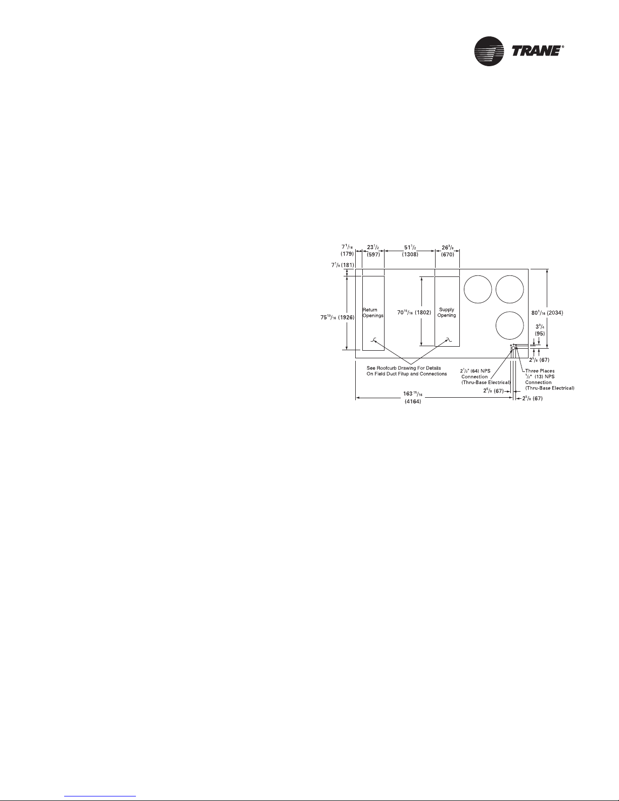
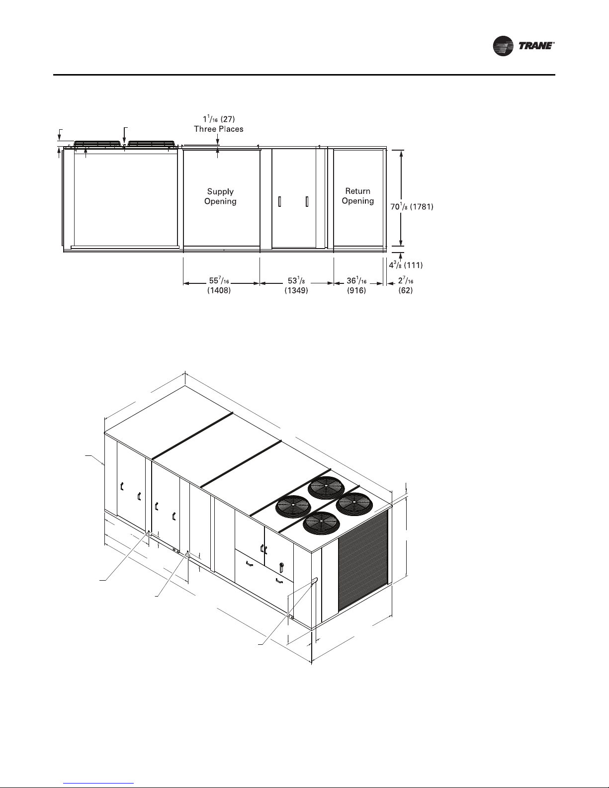
Figure 1. 60 Hz 27½-35, 50 Hz 23-29 Tons (TCD, TED,
YCD l ow heat)
If a Trane curb accessory kit is not used:
a. The ductwork can be attached directly to the S/A
and R/A openings. Be sure to use a flexible duct
connector at the unit.
b. For “built-up” curbs supplied by others, gaskets
must be installed around the curb perimeter flange,
Supply Air opening, and Return Air openings.
c. Insulation must be installed on the bottom of the
condenser section of the unit.
Horizontal Ductwork
When attaching the ductwork to a horizontal supply or
horizontal return unit, provide a water tight flexible
connector at the unit to prevent noise transmission from
RT-SVX34F-EN 13
Page 14
Unit Dimensions and Weights
1 1/4
(32)
3 1/4
(81)
NOTES:
1. SEE DETAIL HOOD DRAWING FOR HORIZONTAL /
DOWNFLOW UNITS FOR ADDITIONAL DIMENSION
AND LOCATION.
179 3/4"
4565.65mm
42"
1066.8mm
83 13/16"
2128.8mm
90 1/16"
2287.5mm
180 5/16"
4579.9mm
90 3/8"
2295.5mm
5 3/8"
136.5mm
7 9/16"
192.1mm
3.25 [82.55mm] TO TOP OF FAN GRILLE
70 7/16"
1789.1mm
40 3/16"
1020.7mm
6 7/8"
174.6mm
1 1/4" [31.7mm]
FEMALE
PVC PIPE
3/4" [19.0mm] NPT
GAS INLET
SEE NOTE 2
CUSTOMER
CONNECTION POINT
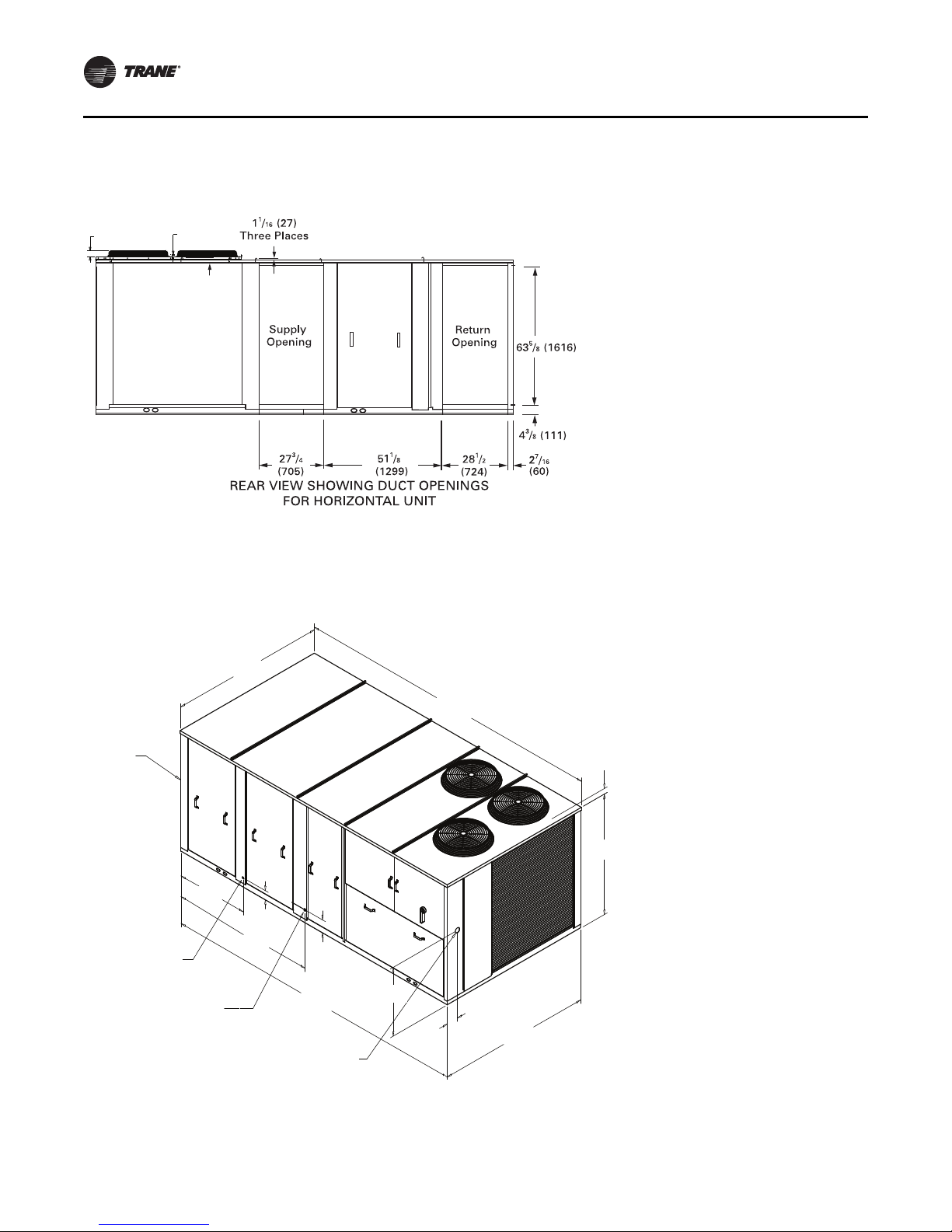
Figure 2. Rear view showing duct openings for horizontal supply and return, 60 Hz 27½-35, 50 Hz 23-29 Tons (TCH,
TEH, YCH low heat)
Notes:
• For combination of horizontal and downflow openings
• On horizontal units, the VFD is located between the
supply and return ductwork, which makes access
limited.
Figure 3. 60 Hz 27½-35, 50 Hz 23-29 Tons (TC, TE, YC low heat)
(digit 3 = F or R) see Figure 1, p. 13 for appropriate
downflow/upflow dimensions and Figure 2, p. 14 for
appropriate horizontal dimensions.
Note: Dimensions in ( ) are mm, 1”= 25.4 mm.
14 RT-SVX34F-EN
Page 15
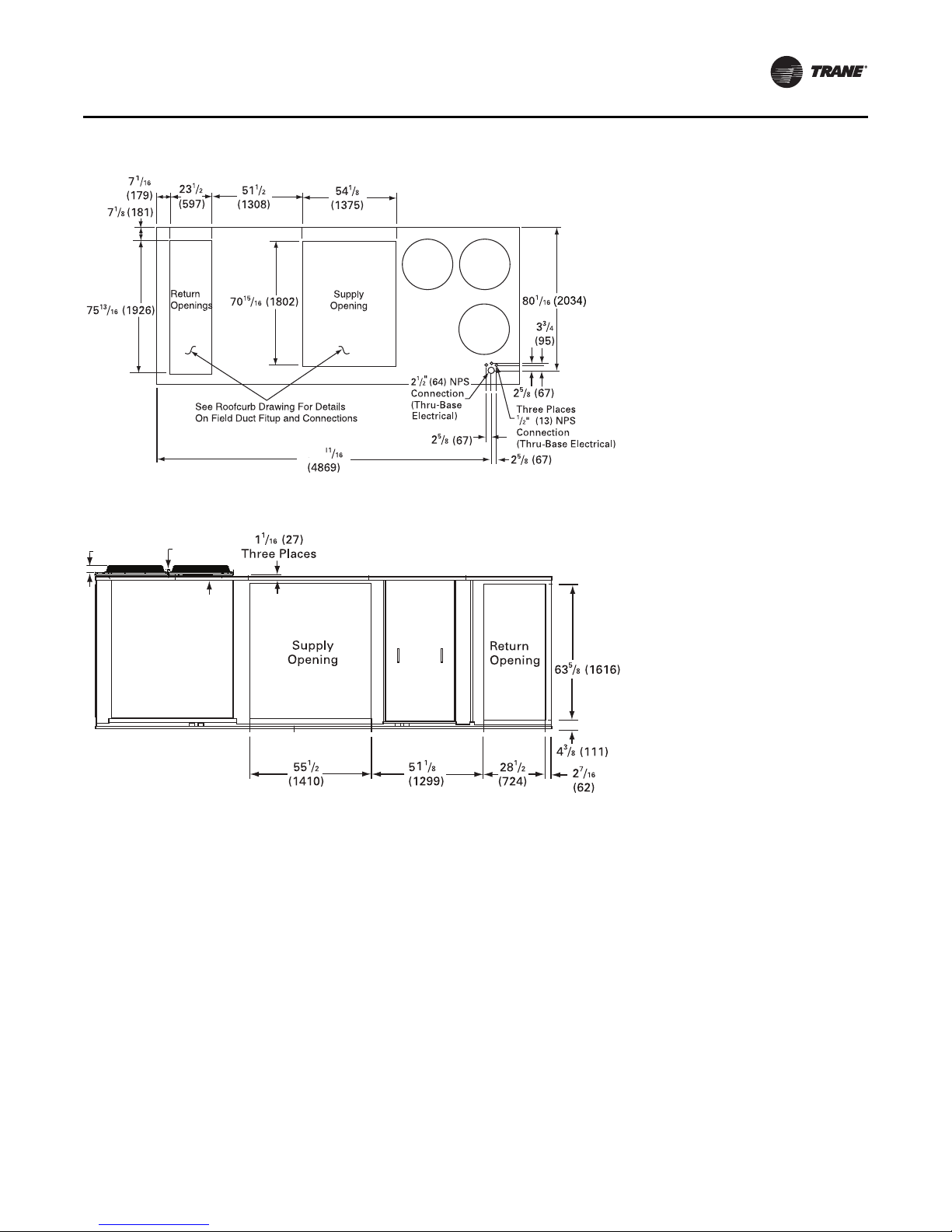
Figure 4. 60 Hz 27½-35, 50 Hz 23-29 Tons (YD high heat)
1 1/4
(32)
3 1/4
(81)
191
Figure 5. Duct openings, 60 Hz 27½-35, 50 Hz 23-29 Tons (YH high heat)
Unit Dimensions and Weights
Notes:
• On horizontal units, the VFD is located between the
supply and return ductwork, which makes access
limited.
• For combination of horizontal and downflow openings
(digit 3 = F or R) see Figure 4, p. 15 for appropriate
downflow/upflow dimensions and Figure 5, p. 15 for
appropriate horizontal dimensions.
RT-SVX34F-EN 15
Page 16
Unit Dimensions and Weights
5270.5mm
207 1/2"
42"
5 3/8"
83 13/16"
2128.8mm
7 9/16"
208 1/16"
5284.7mm
90 5/8"
2301.8mm
90 1/16"
70 7/16"
40 3/16"
6 15/16"
PVC PIPE FEMALE
1" [25.4MM] NPT
GAS INLET
NOTES:
1. SEE ROOFCURB DRAWING FOR DETAILS
ON FIELD DUCT FITUP AND CONNECTIONS
2. SEE DETAIL HOOD DRAWING FOR HORIZONTAL /
DOWNFLOW UNITS FOR ADDITIONAL DIMENSION
AND LOCATION.
SEE NOTE 2
CUSTOMER
CONNECTION POINT
1066.8mm
2287.5mm
136.5m
192.1m
3.25 [82.55mm] TO
TOP OF FAN GRILLE
1789.1mm
1020.7mm
174.6mm
1 1/4" [31.7mm]
Figure 6. 60 Hz 27½-35, 50 Hz 23-29 Tons (YC high heat)
Note: Dimensions in ( ) are mm, 1”= 25.4 mm.
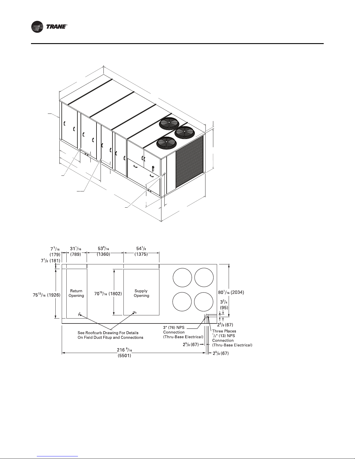
Figure 7. 60 Hz 40-50, 50 Hz 33-42 Tons (TD, TD, YD low and high heat)
16 RT-SVX34F-EN
Page 17
Unit Dimensions and Weights
1 1/4
(32)
3 1/4
(81)
7 9/16"
232 3/8"
5902.3mm
232 3/4"
5911.8mm
90 5/8"
49 9/16"
1258.8mm
93 3/8"
2371.7mm
5 5/16"
90 1/16"
77"
1955.8mm
46 15/16"
1192.2mm
4 3/4"
120.6mm
NOTES:
1. SEE ROOFCURB DRAWING FOR DETAILS
ON FIELD DUCT FITUP AND CONNECTIONS
2. SEE DETAIL HOOD DRAWING FOR HORIZONTAL /
DOWNFLOW UNITS FOR ADDITIONAL DIMENSION
AND LOCATION.
SEE NOTE 2
CUSTOMER
CONNECTION POINT
2301.8mm
PVC PIPE FEMALE
1" [25.4MM] NPT
HIGH HEAT GAS INLET
2287.5mm
136.5m
192.1m
3.25 [82.55mm] TO
TOP OF FAN GRILLE
1 1/4" [31.7mm]
3/4" [19MM] NPT
LOW HEAT GAS INLET
Figure 8. Duct openings, 60 Hz 40-50, 50 Hz 33-42 Tons (TH, TH, YH low and high heat)
Notes:
• On horizontal units, the VFD is located between the
supply and return ductwork, which makes access
limited.
• For combination of horizontal and downflow openings
(digit 3 = F or R) see Figure 7, p. 16 for appropriate
downflow/upflow dimensions and Figure 8, p. 17 for
appropriate horizontal dimensions.
Figure 9. 60 Hz 40-50, 50 Hz 33-42 Tons (TC, TE, YC low and high heat)
Note: Dimensions in ( ) are mm, 1”= 25.4 mm.
RT-SVX34F-EN 17
Page 18
Unit Dimensions and Weights
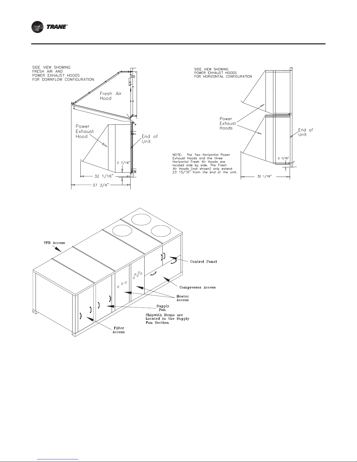
Figure 10. Fresh air and power exhaust dimensions for TC*, TE*, and YC* units
Figure 11. Location of “Ship With” items for TC*, TE*, and YC* units
18 RT-SVX34F-EN
Page 19
Unit Dimensions and Weights
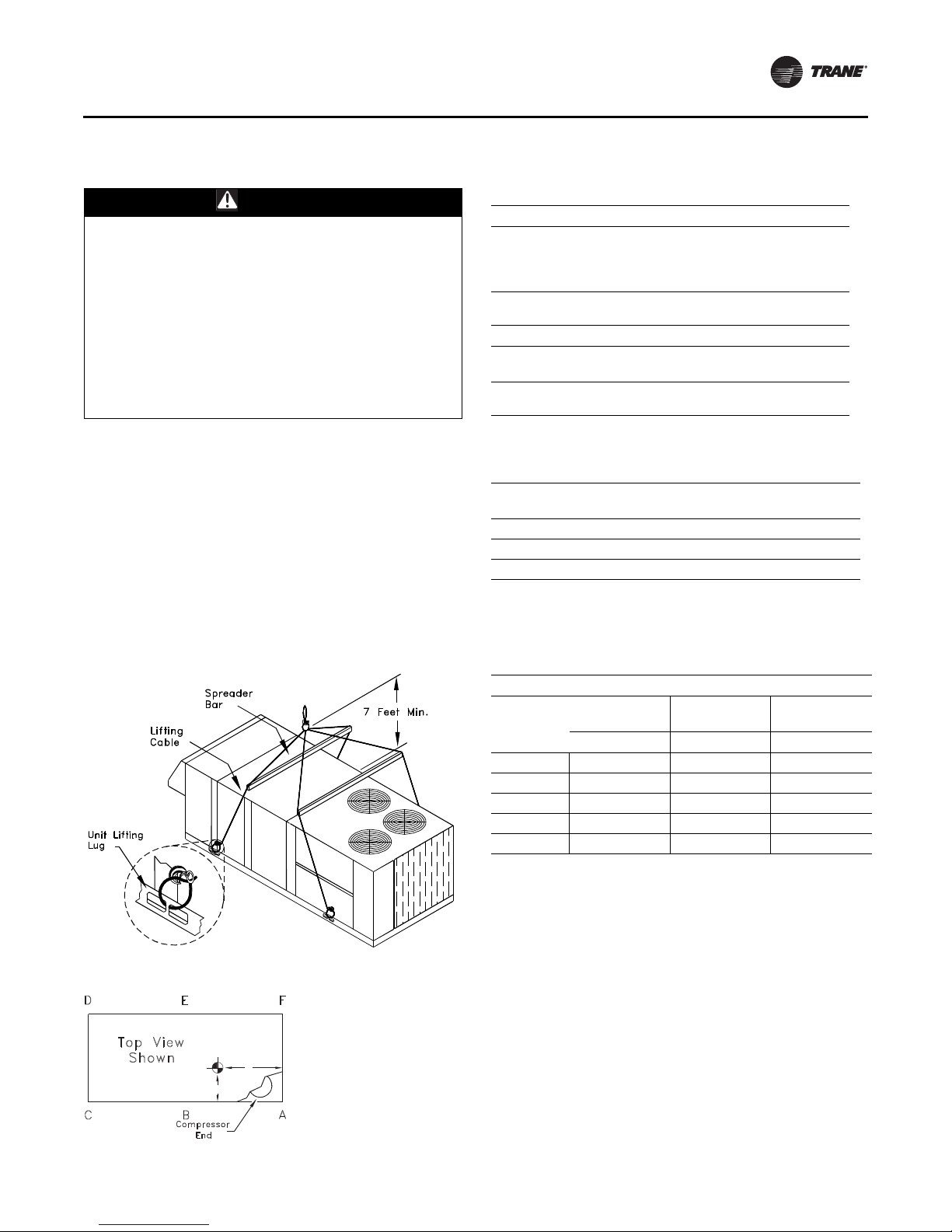
Unit Rigging and Placement
WARN ING
Heavy Objects!
Ensure that all the lifting equipment used is properly
rated for the weight of the unit being lifted. Each of the
cables (chains or slings), hooks, and shackles used to
lift the unit must be capable of supporting the entire
weight of the unit. Lifting cables (chains or slings) may
not be of the same length. Adjust as necessary for even
unit lift. Other lifting arrangements could cause
equipment or property damage. Failure to follow
instructions above or properly lift unit could result in
unit dropping and possibly crushing operator/
technician which could result in death or serious injury.
Use spreader bars as shown in the diagram. Refer to the
Installation manual or nameplate for unit weight. Refer to
the Installation instructions located inside the control
panel for further rigging information.
1. Verify that the roof curb has the proper gaskets
installed and is level and square to assure an adequate
curb-to-unit seal.
The units must be as level as possible in order to
assure proper condensate flow out of the unit. The
maximum side-to-side and end-to-end slope allowable
in any application is listed in Table 2, p. 19.
Table 1. Minimum operating clearances installation
(horizontal, downflow, and mixed airflow
configurations)
Recommended Clearances
Condenser
(a)
Coil
Single Unit
TC*, TE*, YC*
27.5 to 50 Tons
Multiple Unit
TC*, TE*, YC*
27.5 to 50 Tons
(a) Condenser coil is located at the end and side of the unit.
Economizer/
Exhaust End
6 Feet 8 Feet 4 Feet
Distance Between Units
Economizer/
Exhaust End End/Side
12 Feet 16 Feet 8 Feet
Orientation
End/Side
Service Side
Access
Service Side
Access
Table 2. Maximum slope
Cabinet
“A” (27.5 - 35 Ton Low Heat) 3 1/2 1 5/8
“B” (27.5 - 35 Ton High Heat) 4 1 5/8
“C” (All 40 and 50 Ton Units) 4 1/2 1 5/8
Note: Do not exceed these allowances. Correct the improper slope by
building up the curb base. The material used to raise the base must
be adequate to support both the curb and the unit weight.
End to End
(inches)
Side to Side
(inches)
Figure 12. Unit rigging
Figure 13. Center of gravity
Y
Z (see note 2)
X
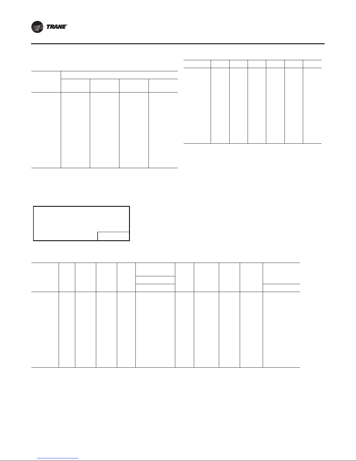
Table 3. Center of gravity
Center-of-Gravity (inches)
YC Low Heat
Dimension
Unit Model
***330/275* 41 76 33 41 84 33 42 76 33
***360/305* 43 77 33 43 85 33 44 77 33
***420/350* 42 78 33 42 86 33 43 78 33
***480/400* 42 111 35 42 111 35 42 111 35
***600/500* 43 108 35 43 108 35 43 108 35
Note: Center-of-gravity dimensions are approximate, and are based on the
unit equipped with: standard efficiency coils, standard efficiency
motors, economizer, and throwaway filters.
Note: Z dimension is upward from the base of the unit.
Example:
Locating the center-of-gravity for a YC-360 MBH High Heat unit with 100%
exhaust.
X = 43 inches inward from the control panel side
Y = 85 inches inward from the compressor end
Z = 33 inches upward from the base
XY ZXY ZXY Z
YC High Heat
Dimension
TC/TE
Dimension
RT-SVX34F-EN 19
Page 20
Unit Dimensions and Weights
DE F
TOP VIEW
OF UNIT
COMPRS
CBA
Table 4. Approximate units operating weights — lbs./
Unit
Model
**D330/275 3750 1701 4130 1873 3620 1642 3640 1651
**H330/275 3790 1719 4220 1914 3660 1660 3680 1669
**D360/305 3845 1744 4225 1916 3715 1685 3735 1694
**H360/305 3885 1762 4315 1957 3755 1703 3775 1712
**D420/350 3970 1801 4350 1973 3840 1742 3860 1751
**H420/350 4010 1819 4440 2014 3880 1760 3900 1769
**D480/400 4764 2161 4884 2215 4539 2059 4564 2070
**H480/400 4859 2204 4984 2261 4599 2091 4634 2102
**D600/500 5174 2347 5294 2401 4949 2245 4974 2256
**D600/500 5269 2390 5394 2447 5019 2277 5044 2288
Notes:
1. Basic unit weight includes minimum horsepower supply fan
motor.
1
kg
Basic Unit Weights
1
YC
Low HeatYCHigh Heat TC TE
Table 5. Point loading average weight
1,2
— lbs./kg
Model A B C D E F
**D330/275 846 384 688 313 743 337 745 338 604 275 503 228
**H330/275 867 393 707 321 767 348 753 342 613 279 513 233
**D360/305 836 379 680 309 779 353 741 336 621 285 568 258
**H360/305 897 407 696 316 766 348 729 330 590 268 636 288
**D420/350 892 405 692 314 779 353 765 347 633 288 590 268
**H420/350 867 393 869 395 690 313 758 344 601 273 654 297
**D480/400 820 372 856 388 937 425 742 336 762 346 769 349
**H480/400 841 381 876 397 957 434 754 342 775 352 782 355
**D600/500 894 406 955 428 970 440 756 343 862 391 866 393
**H600/500 915 415 966 438 990 449 768 348 875 397 879 399
Notes:
1. Point Loading is identified with corner A being the corner with the
compressors. As you move clockwise around the unit as viewed
from the top, mid-point B, corner C, corner D, mid-point E and
corner F.
2. Point load calculations provided are based on the unit weight for YC
high heat gas models.
Table 6. Approximate operating weights1— optional components — lbs./kg
Unit
Model
**D330/275 110/50 165/74 50/23 260/117 85/39 115/52 18/8 6/3 30/14 85/38 310/141 330/150
**H330/300 145/65 200/90 50/23 285/128 85/39 115/52 18/8 6/3 30/14 85/38 310/141 330/150
**D360/305 110/50 165/74 50/23 260/117 85/39 115/52 18/8 6/3 30/14 85/38 310/141 330/150
**H330/305 145/65 200/90 50/23 285/128 85/39 115/52 18/8 6/3 30/14 85/38 310/141 330/150
**D420/350 110/50 165/74 50/23 260/117 85/39 115/52 18/8 6/3 30/14 85/38 310/141 330/150
**H420/350 145/65 200/90 50/23 285/128 85/39 115/52 18/8 6/3 30/14 85/38 310/141 330/150
**D480/400 110/50 165/74 50/23 290/131 115/52 150/68 18/8 6/3 30/14 85/38 365/169 365/169
**H480/400 145/65 200/90 50/23 300/135 115/52 150/68 18/8 6/3 30/14 85/38 365/169 365/169
**D600/500 110/50 165/74 50/23 290/131 115/52 150/68 18/8 6/3 30/14 85/38 365/169 365/169
**H600/500 145/65 200/90 50/23 300/135 115/52 150/68 18/8 6/3 30/14 85/38 365/169 365/169
Note:
1. Basic unit weight includes minimum horsepower supply fan motor.
Baro.
Relief
Power
Exhaust
0-25%
Man
Damper Econ.
20 RT-SVX34F-EN
Var. Freq.
Drives (VFD’s)
Bypass Lo Hi
Valves
Serv
Through-
the
base
Elec.
Non-
Fused
Discon.
Switch
Factory.
GFI with
Discon.
Switch
Roof CurbW/O With
Page 21
Installation General Requirements
Condensate Drain Connection
Each commercial rooftop unit is equipped with one (1) 11/4 inch Female PVC condensate drain connection.
Refer to Figure 11, p. 18 for the location of the connector.
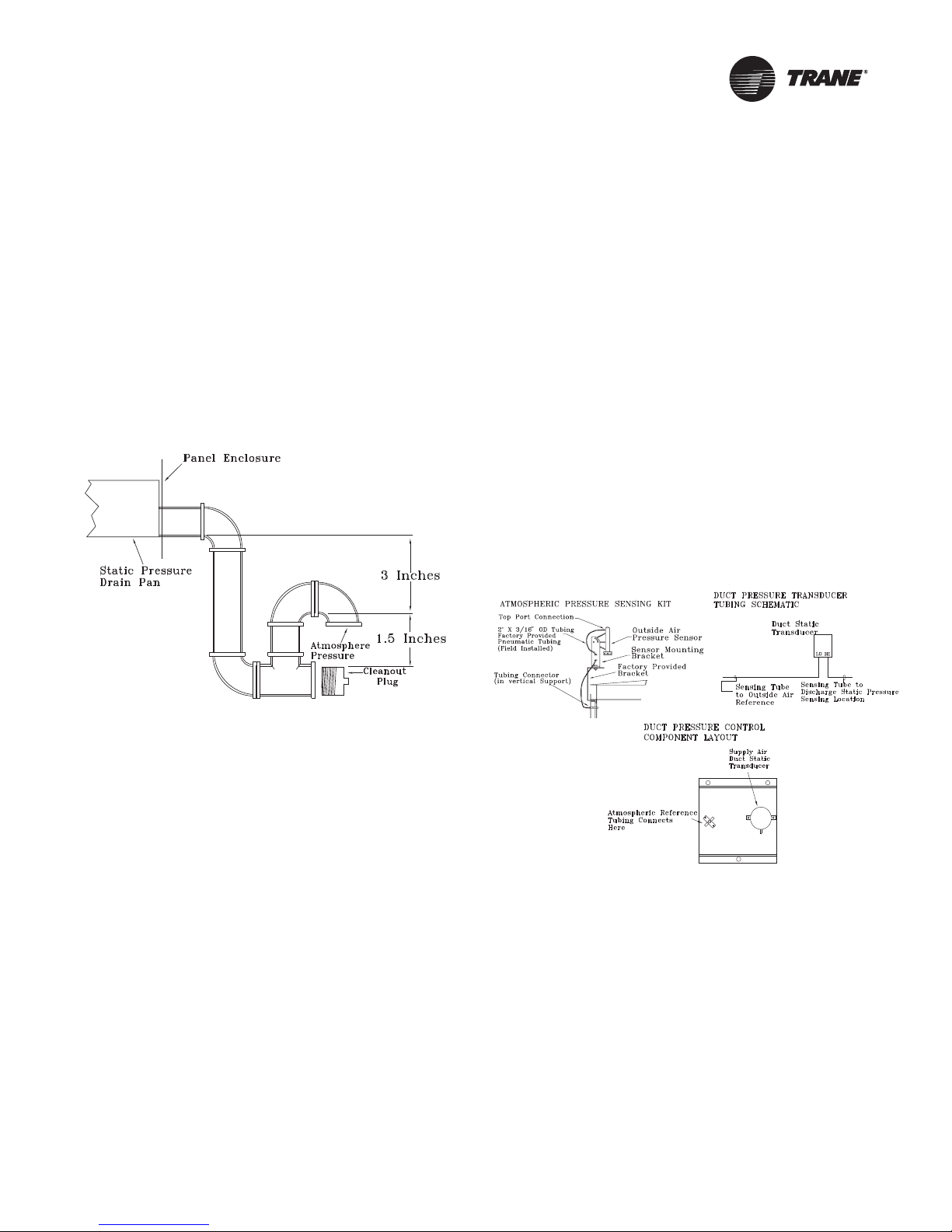
A condensate trap must be installed due to the drain
connection being on the “negative pressure” side of the
fan. Install a P-Trap at the unit using the guidelines in
Figure 14, p. 21.
Pitch the drain line at least 1/2 inch for every 10 feet of
horizontal run to assure proper condensate flow.
Ensure that all condensate drain line installations comply
with applicable building and waste disposal codes.
Figure 14. Condensate trap installation
4. Remove the dust cap from the tubing connector
located below the sensor in the vertical support.
5. Attach one end of the 50' x 3/16” O.D. factory provided
pneumatic tubing to the sensor's top port, and the
other end of the tubing to the connector in the vertical
support. Discard any excess tubing.
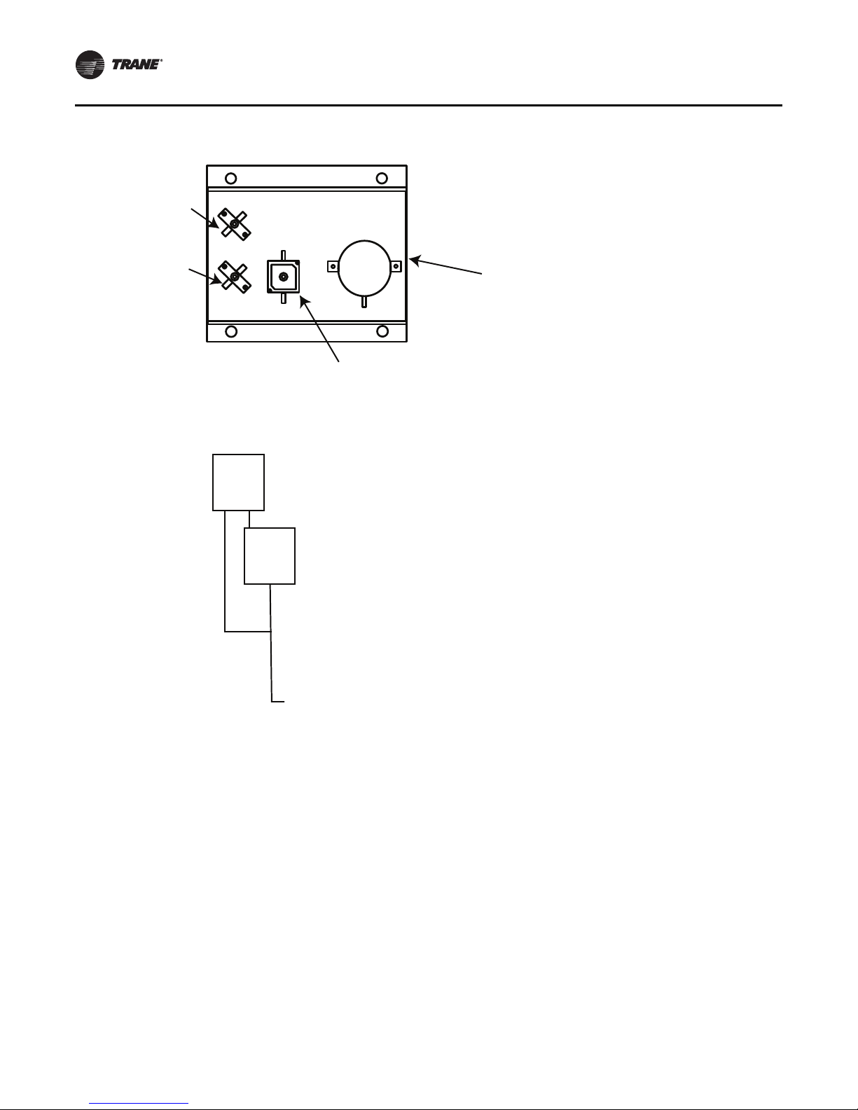
Units with Statitrac™
1. Open the filter access door, and locate the Statitrac
Transducer Assembly illustrated in Figure 16, p. 22.
There are two tube connectors mounted on the left of
the solenoid and transducers. Connect one end of the
field provided 1/4” (length 50-100 ft.) or 3/8” (length
greater than 100 ft.) O.D. pneumatic tubing for the
space pressurization control to the fitting indicated in
the illustration.
2. Route the opposite end of the tubing to a suitable
location inside the building. This location should be
the largest open area that will not be affected by
sudden static pressure changes.
Figure 15. Pressure tubing
O/A Sensor & Tubing Installation
An Outside Air Pressure Sensor is shipped with all units
designed to operate on traditional variable air volume
applications (non-SZ VAV) and units with Statitrac™.
A duct pressure transducer and the outside air sensor is
used to control the discharge duct static pressure to within
a customer-specified controlband. Refer to the illustration
in Figure 15, p. 21 and the following steps to install the
sensor and the pneumatic tubing.
1. Remove the O/A pressure sensor kit located inside the
fan section. The kit contains the following items;
• an O/A static pressure sensor
• a sensor mounting bracket
• 50’ of 3/16” O.D. pneumatic tubing
• mounting hardware
2. Using two #10-32 x 1-3/4” screws provided, install the
sensor's mounting bracket to the factory provided
bracket (near the fan section).
3. Using the #10-32 x 1/2” screws provided, install the O/
A static pressure sensor vertically to the sensor
bracket.
RT-SVX34F-EN 21
Page 22
Installation General Requirements
Static Reference
Tubing Connects
Here (O/A Sensor)
Space Pressure
Sensing Tube
Connects Here
Space Pressure
Calibration
Solenoid
Space Pressure
Transducer
LO
HI
CNO
NC
Sensing Tube
to Outside Air
Reference
Space Pressure
Transducer
Sensing Tube
to Space
Pressure
Figure 16. Statitrac transducer assembly
22 RT-SVX34F-EN
Page 23
Installation Electrical
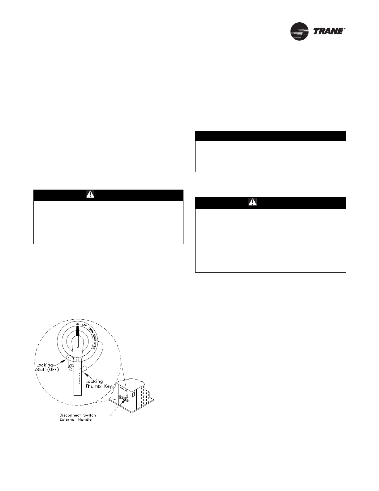
Disconnect Switch External
Handle (Factory Mounted Option)
Units ordered with the factory mounted disconnect switch
come equipped with an externally mounted handle. This
allows the operator to disconnect power from the unit
without having to open the control panel door. The handle
location and its three positions are shown below;
ON - Indicates that the disconnect switch is closed,
allowing the main power supply to be applied at the unit.
OFF - Indicates that the disconnect switch is open,
interrupting the main power supply at the unit.
OPEN COVER/RESET - Turning the handle to this position
releases the handle from the disconnect switch, allowing
the control panel door to be opened.
WARNI NG
Hazardous Voltage!
Disconnect all electric power, including remote
disconnects before servicing. Follow proper lockout/
tagout procedures to ensure the power can not be
inadvertently energized. Failure to disconnect power
before servicing could result in death or serious injury.
Once the door has been opened, it can be closed with the
handle in any one of the three positions outlined above,
provided it matches the disconnect switch position. The
handle can be locked in the “OFF” position. While holding
the handle in the “OFF” position, push the spring loaded
thumb key, attached to the handle, into the base slot. Place
the lock shackle between the handle and the thumb key.
This will prevent it from springing out of position.
Figure 17. Disconnect switch
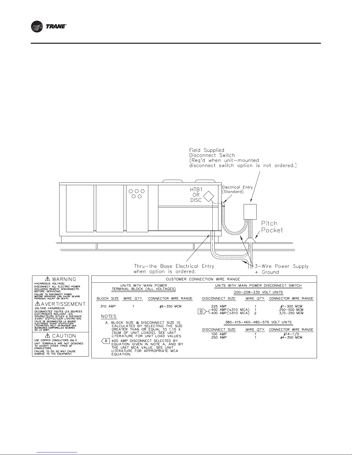
An overall layout of the field required power wiring is
illustrated in Figure 18, p. 24. To insure that the unit supply
power wiring is properly sized and installed, follow the
guidelines outlined below.
Note: All field installed wiring must conform to NEC
guidelines as well as State and Local codes.
Verify that the power supply available is compatible with
the unit's name plate ratings for all components. The
available power supply must be within 10% of the rated
voltage stamped on the nameplate. Use only copper
conductors to connect the 3-phase power supply to the
unit.
NOTICE:
Use Copper Conductors Only!
Unit terminals are not designed to accept other types of
conductors. Failure to use copper conductors could
result in equipment damage.
Main Power Wiring
WARNI NG
Proper Field Wiring and Grounding
Required!
All field wiring MUST be performed by qualified
personnel. Improperly installed and grounded field
wiring poses FIRE and ELECTROCUTION hazards. To
avoid these hazards, you MUST follow requirements for
field wiring installation and grounding as described in
NEC and your local/state electrical codes. Failure to
follow code could result in death or serious injury.
1. Table 7, p. 25 and Ta b le 10 , p . 2 6 list the electrical
service sizing data. The electrical service must be
protected from over current and short circuit
conditions in accordance with NEC requirements.
Protection devices must be sized according to the
electrical data on the nameplate. Refer to “Electrical
Wire Sizing and Protection Device Equations” on
page 27 for determining:
a. The appropriate electrical service wire size based
on “Minimum Circuit Ampacity” (MCA),
b. The “Maximum Over current Protection” (MOP)
device.
c. The “Recommended Dual Element fuse size” (RDE).
2. If the unit is not equipped with an optional factory
installed Nonfused disconnect switch, a field supplied
disconnect switch must be installed at or near the unit
in accordance with the National Electrical Code (NEC
latest edition). Refer to DSS calculations
Wire Sizing and Protection Device Equations” on
page 27 for determining correct size.
Location for the electrical service entrance is shown in
the unit dimensional drawings beginning with
Figure 1, p. 13. Complete the unit's power wiring
connections onto either the main terminal block HTB1,
“Electrical
RT-SVX34F-EN 23
Page 24
Installation Electrical
or the factory mounted nonfused disconnect switch
inside the unit control panel.
Note: When the factory installed through-the-base
option is not used, the installing contractor is
required to seal any holes made in the base of the
unit to prevent water from leaking into the building.
3. Provide proper grounding for the unit in accordance
with local and national codes.
Figure 18. Typical field power wiring
Through-the-Base Electrical (Optional
Accessory)
Liquid-tight conduit couplings are secured to the base of
the unit for both power and control wiring. Liquid-tight
conduit must be field installed between the couplings and
the unit control box to prevent water leaks into the
building.
Note: If the unit is set on the roof curb and temporary
auxiliary heat is provided in the building, it is
recommended that the electrical and control wiring
conduit opening in the control box be temporarily
sealed to provide a vapor barrier.
24 RT-SVX34F-EN
Page 25
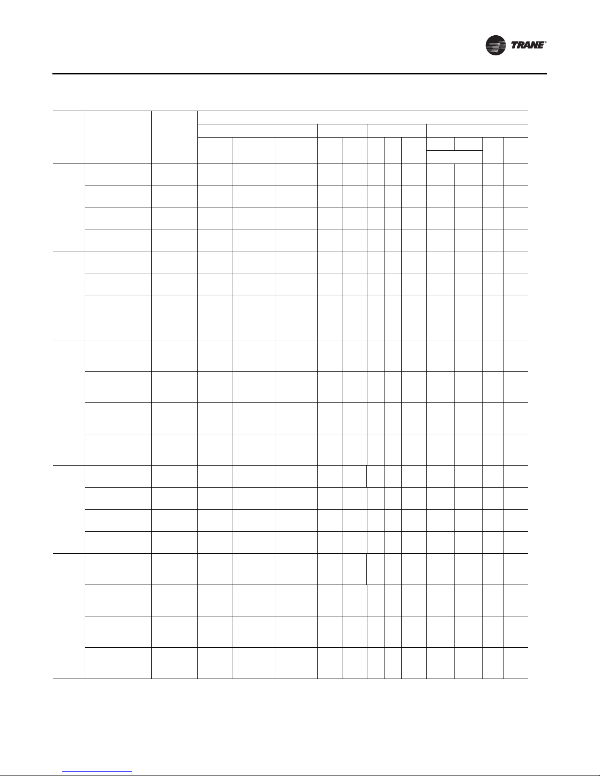
Installation Electrical
Table 7. 27½-50 ton electrical service sizing data—60Hz
1
Fan Motors
Model
TC/TE/
YC*330
TC/TE/
YC*360
TC/TE/
YC*420
TC/TE/
YC*480
TC/TE/
YC*600
Notes:
1. All customer wiring and devices must be installed in accordance with local and national electrical codes.
2. 100% Power Exhaust is with or without Statitrac™.
Characteristics
208/60/3 187-229
230/60/3 207-253
460/60/3 414-506
575/60/3 517-633
208/60/3 187-229 2/13 50.5 315/315
230/60/3 207-253 2/13 50.5 315/315
460/60/3 414-506 2/13 23.0 158/158
575/60/3 517-633 2/13 19.0 136/136
208/60/3 187-229
230/60/3 207-253
460/60/3 414-506
575/60/3 517-633
208/60/3 187-229
230/60/3 207-253
460/60/3 414-506
575/60/3 517-633
208/60/3 187-229
230/60/3 207-253
460/60/3 414-506
575/60/3 517-633
Electrical
Voltage
Range
No/Ton RLA (Ea.) LRA (Ea.) HP FLA No HP
1/12,1/
1/12,1/
1/12,1/
1/12,1/
1/13,1/
1/13,1/
1/13,1/
1/13,1/
1/13,1/
1/13,1/
1/13,1/
1/13,1/
2/13,1/
2/13,1/
2/13,1/
2/13,1/
Allowable
Compressor Supply Condenser Exhaust
7.5
44.0/50.5 304/315
13
44.0/50.5 304/315
13
21.0/23.0 147/158
13
17.5/19.0 122/136
13
50.5/56.0 315/351
15
50.5/56.0 315/351
15
15
23.0/27.5 158/197
15
19.0/23.0 136/146
50.5/83.9 315/485
20
50.5/83.9 315/485
20
23.0/34.0 158/215
20
19.0/27.3 136/175
20
50.5/56.0 315/351
15
50.5/56.0 315/351
15
23.0/27.5 158/197
15
19.0/23.0 136/146
15
10.0
7.5
10.0
7.5
10.0
7.5
10.0
7.5
10.0
7.5
10.0
7.5
10.0
7.5
10.0
7.5
10.0
15.0
7.5
10.0
15.0
7.5
10.0
15.0
7.5
10.0
15.0
10.0
15.0
10.0
15.0
10.0
15.0
10.0
15.0
10.0
15.0
20.0
10.0
15.0
20.0
10.0
15.0
20.0
10.0
15.0
20.0
22.2
3 1.1 7.0 1 2 1.0 4.1
29.5
18.8
3 1.1 7.0 1 2 1.0 4.1
25.2
9.4
3 1.1 3.5 1 2 1.0 1.8
12.6
7.8
3 1.1 2.8 1 2 1.0 1.4
10.1
22.2
3 1.1 7.0 1 2 1.0 4.1
29.5
18.8
3 1.1 7.0 1 2 1.0 4.1
25.2
9.4
3 1.1 3.5 1 2 1.0 1.8
12.6
7.8
3 1.1 2.8 1 2 1.0 1.4
10.1
22.2
29.5
3 1.1 7.0 1 2 1.0 4.1
40.7
18.8
25.2
3 1.1 7.0 1 2 1.0 4.1
35.4
9.4
12.6
3 1.1 3.5 1 2 1.0 1.8
17.7
7.8
10.1
3 1.1 2.8 1 2 1.0 1.4
15.1
29.5
4 1.1 7.0 1 2 1.5 5.4
40.7
25.2
4 1.1 7.0 1 2 1.5 5.4
35.4
12.6
4 1.1 3.5 1 2 1.5 2.7
17.7
10.1
4 1.1 2.8 1 2 1.5 2.2
15.1
29.5
40.7
4 1.1 7.0 1 2 1.5 5.4
56.1
25.2
35.4
4 1.1 7.0 1 2 1.5 5.4
49.4
12.6
17.7
4 1.1 3.5 1 2 1.5 2.7
24.7
10.1
15.1
4 1.1 2.8 1 2 1.5 2.2
19.6
FLA
(Ea.)
50% 100%
HP
FLA
(Ea.)No.
RT-SVX34F-EN 25
Page 26
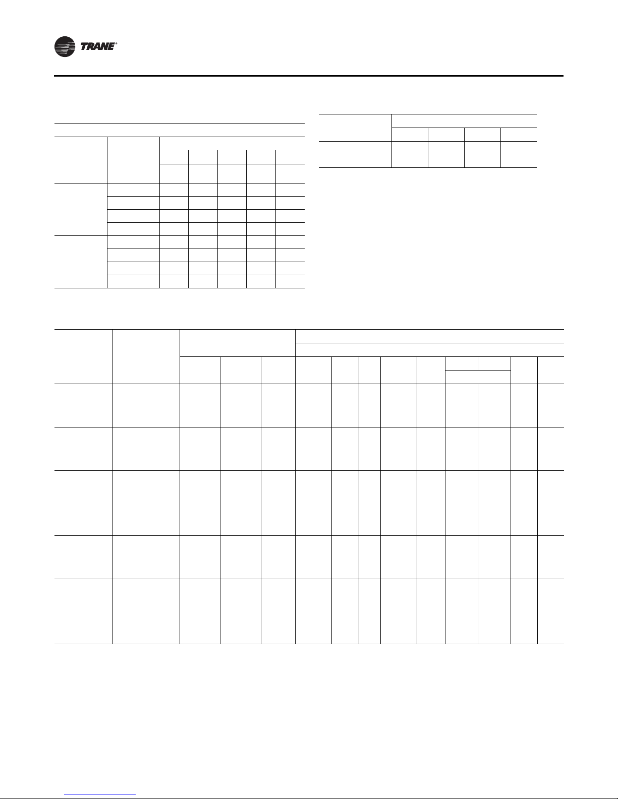
Installation Electrical
Table 8. Electrical service sizing data — electric heat
module (electric heat only) — 60 Hz
Models: TE(D,H,F,R) 330—600 Electric Heat FLA
KW Heater
Nominal
Unit Size
(Tons)
27½-35
40- 50
Note: All FLA in this table are based on heater operating at 208, 240, 480,
and 600 volts.
Nominal
36 54 72 90 108
Unit
Voltage
208 74.9 112.4 — — —
230 86.6 129.9 — — —
460 43.3 65.0 86.6 108.3 —
575 — 52.0 69.3 86.6 —
208 — 112.4 — — —
230 — 129.9 — — —
460 — 65.0 86.6 108.3 129.9
575 — 52.0 69.3 86.6 103.9
FLA FLA FLA FLA FLA
Table 9. Electrical service sizing data — crankcase
heaters (heating mode only) — 60Hz
Nominal
Unit Size (Tons)
27½ - 35 1111
40, 50 2211
FLA Add Unit Voltage
200 230 460 575
Table 10. Electrical service sizing data — 50Hz
Fan Motors
Compressor
Model
TC/TE/YC*275 380-415/50/3 1/10, 1/11 21.0/23.0 147/ 158 7.5 (5.6)
TC/TE/YC*305 380-415/50/3 2/11 23.0 158 7.5 (5.6)
TC/TE/YC*350 380-415/50/3 1/11, 1/12 23.0/27.5 158/ 197 7.5 (5.6)
TC/TE/YC*400 380-415/50/3 1/11, 1/17 23.0/34.0 158/ 215 10 (6.8)
TC/TE/YC*500 380-415/50/3 2/11, 1/12 23.0/27.5 158/ 197 10 (6.8)
Notes:
1. All condenser fan motors are single phase.
2. All customer wiring and devices must be installed in accordance with local and national electrical codes.
3. Allowable voltage range for the 380V unit is 342-418V, allowable voltage range for the 415V unit is 373-456.
4. 100% Power Exhaust is with or without Statitrac.
Characteristics
No/Ton
Electrical
RLA
(Ea.)
LRA
(Ea.) HP(kW) FLA No. HP(kW)
Supply Condenser
10 (6.8)
10 (6.8)
10 (6.8)
15 (10.5)
15 (10.5)
15 (10.5)
20 (12.8)
13.6/
16.0/
13.6/
16.0/
13.6/
16.0/
24.0/
16.0/
24.0/
16.0/
24.0/
29.0/
3 .75 (.56) 4.4 1 2
14.1
15.5
3
14.1
15.5
3
14.1
15.5
26.0
4
15.5
26.0
4
15.5
26.0
28.0
0.75
(0.56)
0.75
(0.56)
0.75
(0.56)
0.75
(0.56)
1
50% 100%
FLA
(Ea.)
4.4 1 2
4.4 1 2
4.4 1 2
4.4 1 2
Exhaust
4
(kW)
(0.56)
(0.56)
(0.56)
(0.75)
(0.75)
HP
0.75
0.75
0.75
1.0
1.0
FLA
(Ea.)No.
1.7
1.7
1.7
2.5
2.5
26 RT-SVX34F-EN
Page 27
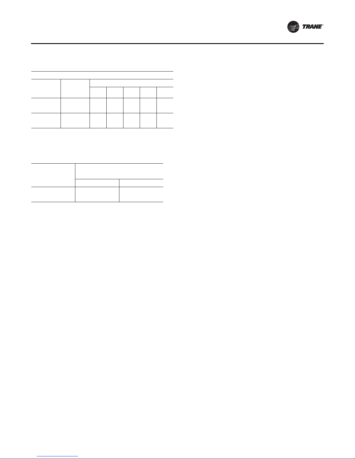
Table 11. Electrical service sizing data – electric heat
module (electric heat units only)—50Hz
Models: TE(D,H,F,R) 275 through 500 Electric Heat FLA
Nominal
Unit Size
(Tons)
23-29
33, 42
Note: All FLA in this table are based on heater operating at 380 or 415 volts
as shown above.
Nominal
Unit
Voltage
380 34.5 51.1 68.9 85.5 –
415 37.6 55.6 – – –
380 – 51.1 68.9 85.5 103.4
415 – 55.6 75.1 93.2 112.7
KW Heater (380/415V)
23/27 34/40 45/54 56/67 68/81
Table 12. Electrical service sizing data — crankcase
heaters (heating mode only) — 50Hz
FLA Add
Nominal Unit Size
(Tons)
23 - 29 1 1
33 - 42 1 1
Unit Voltage
380 415
Electrical Wire Sizing and
Protection Device Equations
To correctly size the main power wiring based on MCA
(Minimum Circuit Ampacity), use the appropriate
equation listed below. Read the definitions that follow and
then use Calculation #1 for determining MCA (Minimum
Circuit Ampacity), MOP (Maximum Over current
Protection), and RDE (Recommended Dual Element fuse
size) for TC (Cooling Only) units and YC (Cooling with Gas
Heat) units. Use Calculation #2 for TE (Cooling with Electric
Heat) units.
Load Definitions:
• LOAD 1 = CURRENT OF THE LARGEST MOTOR
(Compressor or Fan Motor)
• LOAD 2 = SUM OF THE CURRENTS OF ALL
REMAINING MOTORS
• LOAD 3 = FLA (Full Load Amps) OF THE ELECTRIC
HEATER
• LOAD 4 = ANY OTHER LOAD RATED AT 1 AMP OR
MORE
• CRANKCASE HEATERS FOR HEATING MODE ONLY:
• 208/230 VOLT
– 27.5 - 35 Ton Units, Add 1 Amp
– 40 - 50 Ton Units, Add 2 Amps
• 460/575 VOLT
– 27.5 - 35 Tons Units, Add 1 Amp
– 40 - 50 Ton Units, Add 1 Amp
Installation Electrical
Calculation #1 - TC*, YC*-27.5 to 50 Ton Units
MCA = (1.25 x Load 1) + Load 2 + Load 4
MOP = (2.25 x Load 1) + Load 2 + Load 4 (See Note 1)
RDE = (1.5 x Load 1) + Load 2 + Load 4 (See Note 2)
Calculation # 2 - TE*-27.5 to 50 Ton Units
A. Single Source Power (all voltages)
To calculate the correct MCA (Minimum Circuit Ampacity),
MOP (Maximum Over current Protection), and RDE
(Recommended Dual Element fuse size), two (2) sets of
calculations must be performed;
1. Calculate the MCA, MOP and/or RDE values using the
above equation as if the unit is operating in the cooling
mode.
2. Calculate the MCA, MOP and/or RDE values as if the
unit is operating in the heating mode, as follows:
Note: When determining loads, the compressors and
condenser fan motors do not operate during the
heating cycle.
Units with less than 50 KW Heaters
MCA = 1.25 x (Load 1 + Load 2 + Load 4) + (1.25 x Load 3)
Units with 50 KW or Larger Heaters
MCA = 1.25 x (Load 1 + Load 2 + Load 4) + Load 3
The MCA value stamped on the nameplate is the largest of
the two calculated values.
MOP = (2.25 x Load 1) + Load 2 + Load 3 + Load 4 (See Note
1)
The MOP value stamped on the nameplate is the largest of
the two calculated values.
RDE = (1.5 x Load 1) + Load 2 + Load 3 + Load 4 (See Note 2)
Note: Select an over current protection device equal to
the MOP value. If the calculated MOP value does
not equal a standard size protection device listed in
NEC 240-6, select the next lower over current
protection device. If the calculated MOP value is
less than the MCA value, select the lowest over
current protection device which is equal to or larger
than the MCA, providing the selected over current
device does not exceed 800 amps.
Note: Select a Dual Element Fuse equal to the RDE value.
If the calculated RDE value does not equal a
standard dual element fuse size listed in NEC 2406, select the next higher fuse size. If the calculated
RDE value is greater than the MOP value, select a
Dual Element fuse equal to the calculated MOP
(Maximum Over current Protection) value
RT-SVX34F-EN 27
Page 28

Installation Electrical
Disconnect Switch Sizing (DSS)
Calculation A. - YC*, TC*, and TE* Units:
DSS = 1.15 X (LOAD1 + LOAD2 + LOAD4)
For TE* units, use calculations A and B.
Calculation B. - TE* Units:
DSS = 1.15 X (LOAD3 + Supply Fan FLA + Exhaust
Fan FLA).
Use the larger value of calculations A or B to size the
electrical disconnect switch.
Low Voltage Wiring
An overall layout of the various control options available
for a Constant Volume application is illustrated in
Figure 19, p. 30 and Figure 20, p. 31 illustrates the various
control options for a Variable Air Volume application. The
required number of conductors for each control device are
listed in the illustration.
A typical field connection diagram for the sensors and
other options are shown in the following section “Remote
Panels and Sensors”. These diagrams are representative of
standard applications and are provided for general
reference only. Always refer to the wiring diagram that
shipped with the unit for specific electrical schematic and
connection information.
Note: All field wiring must conform to NEC guidelines as
well as state and local codes.
Control Power Transformer
WARN ING
Hazardous Voltage!
Disconnect all electric power, including remote
disconnects before servicing. Follow proper lockout/
tagout procedures to ensure the power can not be
inadvertently energized. Failure to disconnect power
before servicing could result in death or serious injury.
The 24 volt control power transformers are equipped with
internal circuit breakers. They are to be used only with the
accessories called out in this manual. If a circuit breaker
trips, be sure to turn off all power to the unit before
attempting to reset it.
On units equipped with the VFD option, an additional
control power transformer is used. The secondary is
protected with fuses. Should the fuse blow, be sure to turn
off all power to the unit before attempting to replace it.
Field Installed AC Control Wiring
WARNI NG
Proper Field Wiring and Grounding
Required!
All field wiring MUST be performed by qualified
personnel. Improperly installed and grounded field
wiring poses FIRE and ELECTROCUTION hazards. To
avoid these hazards, you MUST follow requirements for
field wiring installation and grounding as described in
NEC and your local/state electrical codes. Failure to
follow code could result in death or serious injury.
NOTICE:
Use Copper Conductors Only!
Unit terminals are not designed to accept other types of
conductors. Failure to use copper conductors could
result in equipment damage.
Before installing any connecting wiring, refer to Tab l e 13 ,
p. 28 for conductor sizing guidelines and;
• Use copper conductors unless otherwise specified.
• Ensure that the AC control voltage wiring between
the controls and the unit's termination point does
not exceed three (3) ohms/conductor for the length
of the run.
Note: Resistance in excess of 3 ohms per conductor may
cause component failure due to insufficient AC
voltage supply.
• Refer to dimensional information beginning with
Figure 1, p. 13 for the electrical access locations
provided on the unit.
• Do not run the AC low voltage wiring in the same
conduit with the high voltage power supply wiring.
Be sure to check all loads and conductors for grounds,
shorts, and miswiring. After correcting any discrepancies,
reset the circuit breakers by pressing the black button
located on the left side of the transformer.
Table 13. AC conductors
Distance from unit to control Recommended wire size
000-460 feet 18 gauge
461-732 feet 16 gauge
733-1000 feet 14 gauge
28 RT-SVX34F-EN
Page 29
Installation Electrical
Field Installed DC Control Wiring
WARN ING
Proper Field Wiring and Grounding
Required!
All field wiring MUST be performed by qualified
personnel. Improperly installed and grounded field
wiring poses FIRE and ELECTROCUTION hazards. To
avoid these hazards, you MUST follow requirements for
field wiring installation and grounding as described in
NEC and your local/state electrical codes. Failure to
follow code could result in death or serious injury.
NOTICE:
Use Copper Conductors Only!
Unit terminals are not designed to accept other types
of conductors. Failure to use copper conductors could
result in equipment damage.
Before installing the connecting wiring between the
components utilizing a DC analog output/input signal and
the unit, refer to Table 14, p. 29 for conductor sizing
guidelines and;
• Use standard copper conductor thermostat wire
unless otherwise specified.
• Ensure that the wiring between the controls and the
unit's termination point does not exceed two and a
half (2-1/2) ohms/conductor for the length of the
run.
Note: Resistance in excess of 21/2 ohms per conductor
can cause deviations in the accuracy of the
controls.
• Refer to dimensional drawings beginning with
Figure 1, p. 13 for the electrical access locations
provided on the unit.
• Do not run the electrical wires transporting DC
signals in or around conduit housing high voltage
wires.
• Must not pass between buildings.
Table 14. DC conductors
Distance from unit to control Recommended wire size
000-150 feet 22 gauge
151-240 feet 20 gauge
241-385 feet 18 gauge
386-610 feet 16 gauge
611-970 feet 14 gauge
Units equipped with the Trane Communication Interface
(TCI) option, which utilizes a serial communication link;
• Must be 18 AWG shielded twisted pair cable Belden
8760 or equivalent).
• Must not exceed 5,000 feet maximum for each link.
RT-SVX34F-EN 29
Page 30
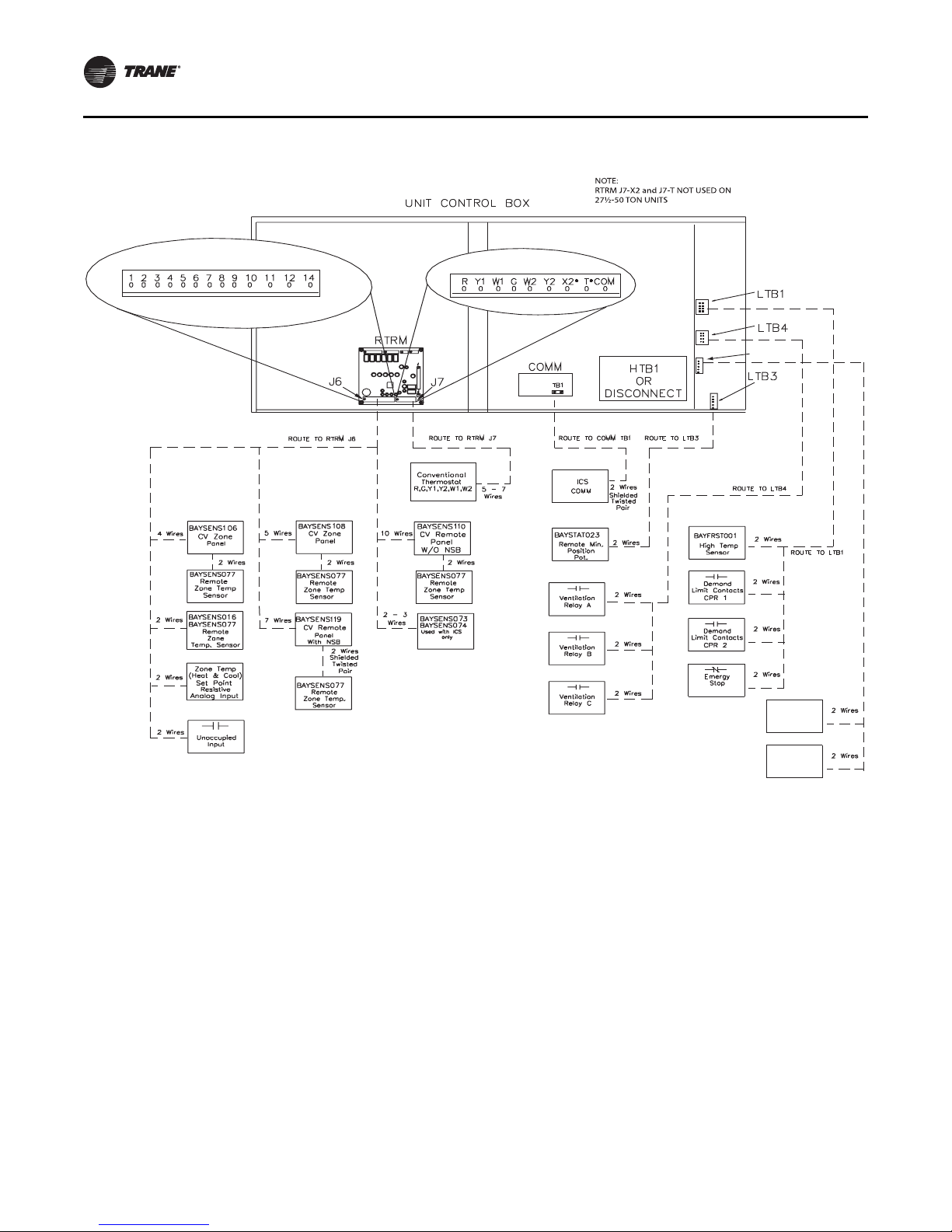
Installation Electrical
LT B6
Space
Humidity
Sensor
Space
Humidistat
RTRM J7 Thermostat Inputs N/A for SZ VAV
Figure 19. Typical field wiring requirements for CV and SZ VAV control options
30 RT-SVX34F-EN
Page 31

Figure 20. Typical field wiring requirements for traditional VAV control options
PROGRAMMABLE
ZSM INPUTS
CV/SZ VAV/VAV
CONVENTIONAL
THERMOSTAT (CV ONLY)
MECHANICAL
ZSM INPUTS
CONVENTIONAL
THERMOSTAT
INPUTS
Installation Electrical
LT B6
*VAV Mode input: RTRM J6-2 to RTRM J6-4
If the unit does not have a Mode (Off, Auto) input from another source,
the following default applies: Short from J6-2 to J6-4 = AUTO mode,
Open from J6-2 to J6-4 = OFF mode.
Figure 21. RTRM zone sensor/thermostat connections
Customer
Changeover
fo r VAV Ht g
(MOD GAS
ONLY
Space
Humidity
Sensor
Space
Humidistat
RT-SVX34F-EN 31
Page 32

Installation Electrical
Remote Panels and Sensors
Constant Volume and Single Zone VAV
Control Options
The RTRM must have a zone sensor or conventional
thermostat (CV only) to operate the rooftop unit. If using a
zone sensor, mode capability depends upon the type of
sensor and/or remote panel selected to interface with the
RTRM. The possibilities are: Fan selection ON or AUTO,
System selection HEAT, COOL, AUTO, and OFF. Refer to
Figure 21, p. 31 for conventional thermostat connections
on Constant Volume units.
The following controls are available from the factory for
field installation on Constant Volume or Single Zone VAV
units.
WARNI NG
Hazardous Voltage!
Disconnect all electric power, including remote
disconnects before servicing. Follow proper lockout/
tagout procedures to ensure the power can not be
inadvertently energized. Failure to disconnect power
before servicing could result in death or serious injury.
Zone Panel (BAYSENS106*)
This electronic sensor features three system switch
settings (Heat, Cool, and Off) and two fan settings (On and
Auto). It is a manual changeover control with single
setpoint capability.
Figure 22. Zone panel (BAYSENS106*)
Figure 23. Zone panel (BAYSENS108*)
Remote Panel W/O NSB (BAYSENS110*)
This electronic sensor features four system switch settings
(Heat, Cool, Auto, and Off) and two fan settings (On and
Auto) with four system status LED's. It is a manual or auto
changeover control with dual setpoint capability. It can be
used with a remote zone temperature sensor
BAYSENS077*.
Figure 24. Remote panel W/O NSB (BAYSENS110*)
Zone Panel (BAYSENS108*)
This electronic sensor features four system switch settings
(Heat, Cool, Auto, and Off) and two fan settings (On and
Auto). It is a manual or auto changeover control with dual
setpoint capability. It can be used with a remote zone
temperature sensor BAYSENS077*.
32 RT-SVX34F-EN
Variable Air Volume (non-SZ VAV) Control
Options
The RTRM must have a mode input in order to operate the
rooftop unit. The normal mode selection used with a
remote panel with or without night setback, or ICS is AUTO
and OFF. Table 15, p. 33 lists the operating sequence
should a CV/SZ VAV zone sensor be applied to a traditional
VAV system having selectable modes; i.e. Fan selection
ON or AUTO. System selection HEAT, COOL, AUTO, and
OFF.
Default Mode Input for Discharge Air Control
For unit stand-alone operation without a remote panel or
an ICS connected, jumper between terminals J6-2 and J64 on RTRM.
VHR Relay Output
For stand alone VAV unit operation, the VHR output should
be wired to drive VAV boxes to maximum position during
Page 33

Installation Electrical
Heat mode/unoccupied mode relay output to VAV
Note:
CUT RESISTOR R69 LOCATED ON RTAM NEAR SUPPLY AIR COOLING
SETPOINT POTENTIOMETER WHEN OPTIONAL REMOTE PANEL IS USED.
CUT WIRE JUMPER ADJACENT TO THE TERMINAL 1 ON ZONE SENSOR
WHEN OPTIONAL REMOTE SENSOR IS USED.
1
2
*
all heating modes and unoccupied periods. The VHR
contacts are shown in the de-energized position and will
switch (energize) during the above mentioned operating
modes.
Figure 25. VHR relay output
Table 15. Variable air volume mode operation
System Mode Fan “Auto” Fan “On”
Heat
Cool VAV Cooling
Auto
Off Off4 Off4
Notes:
1. If Cooling is selected the supply fan will run continuously. If VAV
Heating is activated the supply fan will run continuously.
2. If Daytime Warmup is Activated, the supply fan will run
continuously.
3. Auto changeover between Cooling and Daytime
Warmup depends upon the DWU initiate setpoint.
4. The fan will be Off any time the system selection switch
is “Off”.
DWU Active
DWU Off
DWU Active
DWU Off
2
DWU
4
Off
DWU or
1,2,3,4
Cooling
VAV Cooling
DWU2
VAV Heating
1
VAV Cooling
DWU or
Cooling
VAV Cooling or
1
Heating
1,2,3,4
1
4
1
Figure 26. Remote panel W/O NSB (BAYSENS021*)
The following Constant Volume or Variable Air
Volume (Traditional or Single Zone) controls
are available from the factory for field
installation.
Remote Zone Sensor (BAYSENS073*)
This electronic sensor features remote zone sensing and
timed override with override cancellation. It is used with a
Trane Integrated Comfort
system.
Figure 27. Remote zone sensor (BAYSENS073*)
TM
building management
The following Variable Air Volume controls are
available from the factory for field installation
Remote Zone Sensor (BAYSENS016*)
This bullet type temperature sensor can be used for;
outside air (ambient) sensing, return air temperature
sensing, supply air temperature sensing, remote
temperature sensing (uncovered), and for VAV zone reset.
Wiring procedures vary according to the particular
application and equipment involved. Refer to the unit
wiring diagrams, engineering bulletins, and/or any
specific instructions for connections. See Table 10 for the
Tem p v s Re s i s t a nce coefficient.
Remote Panel W/O NSB (BAYSENS021*)
This electronic sensor features two system switch settings
(Auto and Off), four system status LED's with single
setpoint capability. It can be used with a remote zone
temperature sensor BAYSENS077*.
RT-SVX34F-EN 33
Remote Zone Sensor (BAYSENS074*)
This electronic sensor features single setpoint capability
and timed override with override cancellation. It is used
TM
with a Trane Integrated Comfort
building management
system.
Figure 28. Remote zone sensor (BAYSENS074*)
Page 34

Installation Electrical
Twisted/Shielded
Run Shield to
terminal 11
RTRM
Remote Zone Sensor (BAYSENS077*)
This electronic sensor can be used with BAYSENS106*,
108*, 110*, 119*, or 021* Remote Panels. When this sensor
is wired to a BAYSENS119* Remote Panel, wiring must be
18 AWG Shielded Twisted Pair (Belden 8760 or equivalent).
Refer to the specific Remote Panel for wiring details.
Remote Panel with NSB (BAYSENS119*)
This 7 day programmable sensor features four periods for
Occupied/Unoccupied programming per day. Either one
or all four periods can be programmed. If the power is
interrupted, the program is retained in permanent
memory. If power is off longer than 2 hours, only the clock
and day may have to be reset.
The front panel allows selection of Occupied/Unoccupied
periods with two temperature inputs (Cooling Supply Air
Temperature and Heating Warm-up temperature) per
occupied period. The occupied supply air cooling setpoint
ranges between 40º and 80º Fahrenheit. The warm-up
setpoint ranges between 50º and 90º Fahrenheit with a 2
degrees deadband. The Unoccupied cooling setpoint
ranges between 45º and 98º Fahrenheit. The unoccupied
heating setpoint ranges between 43º and 96º Fahrenheit.
Note: In modulating gas heat units, the supply air heating
setpoint is the active setpoint with a BAYSENS119*
and must be set for the heater to function properly.
The modulating furnace will not react to the
Discharge Heating Setpoint on the NSB.
The liquid crystal display (LCD) displays zone temperature,
temperature setpoints, week day, time, and operational
mode symbols.
The options menu is used to enable or disable these
applicable functions:
Morning warm-up, economizer minimum position
override during unoccupied status, heat installed, remote
zone temperature sensor, 12/24 hour time display, and
daytime warm-up. See Table 16, p. 35 for the Temp vs
Resistance coefficient if an optional remote sensor is used.
During an occupied period, an auxiliary relay rated for 1.25
amps @ 30 volts AC with one set of single pole double
throw contacts is activated.
High Temperature Sensor (BAYFRST003*)
Provides high limit “shutdown” of the unit.
The sensor is used to detect high temperatures due to fire
in the air conditioning or ventilation ducts. The sensor is
designed to mount directly to the sheet metal duct. Each kit
contains two sensors. The return air duct sensor
(X1310004001) is set to open at 135 degrees F. The supply
air duct sensor (X1310004002) is set to open at 240
degrees F. The control can be reset after the temperature
has been lowered approximately 25 degrees F below the
cutout setpoint.
Figure 30. High temperature sensor (BAYFRST003*)
Remote Minimum Position Potentiometer
(BAYSTAT023*)
This device can be used with units with an economizer. It
allows the operator to remotely set the position of the
economizer dampers from 0% to 50% of fresh air entering
the space.
Figure 31. Remote minimum position potentiometer
(BAYSTAT023)
Figure 29. Remote sensor with night setback
BAYSENS119
34 RT-SVX34F-EN
Page 35

Space Temperature Averaging
To RTRM J6-1 and J6-2
or to ZSM terminals 1
and 2 or NSB panel terminals
S1 and S2. Shield to terminal 11
Space temperature averaging is accomplished by wiring a
number of remote sensors in a series/parallel circuit.
The fewest number of sensors required to accomplish
space temperature averaging is four. Example #1
illustrates two series circuits with two sensors in each
circuit wired in parallel. Any number squared, is the
number of remote sensors required. Example #2
illustrates three sensors squared in a series/parallel circuit.
NSB panel remote sensors must use twisted/shielded
cable.
Figure 32. Space temperature averaging
Installation Electrical
Table 16. Temperature vs. resistance (temperature vs.
resistance coefficient is negative)
Degrees F°Nominal
Resistance
-20° 170.1 K - Ohms 50° 19.96 K - Ohms
-15° 143.5 K - Ohms 55° 17.47 K - Ohms
-10° 121.4 K - Ohms 60° 15.33 K - Ohms
-5° 103.0 K - Ohms 65° 13.49 K - Ohms
0° 87.56 K - Ohms 70° 11.89 K - Ohms
5° 74.65 K - Ohms 75° 10.50 K - Ohms
10° 63.80 K - Ohms 80° 9.297 K - Ohms
15° 54.66 K - Ohms 85° 8.247 K - Ohms
20° 46.94 K - Ohms 90° 7.330 K - Ohms
25° 40.40 K - Ohms 95° 6.528 K - Ohms
30° 34.85 K - Ohms 100° 5.824 K - Ohms
35° 30.18 K - Ohms
40° 26.22 K - Ohms
45° 22.85 K - Ohms
RT-SVX34F-EN 35
Degrees
F°
Nominal
Resistance
Page 36

Installation Piping
General Requirements
All internal gas piping for YC* rooftop units are factory
installed and leak tested. Once the unit is set into place, a
gas supply line must be field installed and connected to the
gas train located inside the gas heat compartment.
WARNING
Hazardous Gases and Flammable Vapors!
Exposure to hazardous gases from fuel substances have
been shown to cause cancer, birth defects or other
reproductive harm. Improper installation, adjustment,
alteration, service or use of this product could cause
flammable mixtures or lead to excessive carbon
monoxide. To avoid hazardous gases and flammable
vapors follow proper installation and set up of this
product and all warnings as provided in this manual.
Failure to follow all instructions could result in death or
serious injury.
Access holes are provided on the unit as shown in
Figure 11, p. 18 to accommodate side panel entry.
Following the guidelines listed below will enhance both
the installation and operation of the furnace.
Note: In the absence of local codes, the installation must
conform with the American National Standard
Z223.1a of the National Fuel Gas Code, (latest
edition).
1. To assure sufficient gas pressure at the unit, use
Table 18, p. 37 to determine the appropriate gas pipe
size for the heating capacity listed on the unit's
nameplate.
If a gas line already exists, verify that it is sized large
enough (Table 18, p. 37) to handle the additional
furnace capacity.
2. Take all branch piping from any main gas line from the
top at 90 degrees or side at 45 degrees to prevent
moisture from being drawn in with the gas.
3. Ensure that all piping connections are adequately
coated with joint sealant and properly tightened. Use a
piping compound that is resistant to liquid petroleum
gases.
4. Provide a drip leg near the unit.
NOTICE:
Gas Valve Damage!
• Failure to use a pressure regulating device will result
in incorrect gas pressures. This can cause erratic
operation due to gas pressure fluctuations as well as
damage to the gas valve.
• Oversizing the regulator will cause irregular pulsating
flame patterns, burner rumble, potential flame
outages, as well as possible gas valve damage.
5. Install a pressure regulator at the unit that is adequate
to maintain 6" w.c. for natural gas and 11" w.c. for LP
gas while the unit is operating in the “High Heat”
mode. A minimum inlet gas pressure of 2.5" w.c. for
natural gas and 8" w.c. for LP gas is required while
operating in the “High Heat” mode.
Note: Gas pressure in excess of 14" w.c. or 0.5 psig will
damage the gas train.
WARNING
Hazard of Explosion!
Never use an open flame to detect gas leaks. It could
result in an explosion. Use a leak test solution for leak
testing. Failure to follow recommended safe leak test
procedures could result in death or serious injury or
equipment or property-only-damage.
6. Leak test the gas supply line using a soap-and-water
solution or equivalent before connecting it to the gas
train.
7. Pressure test the supply line before connecting it to the
unit to prevent possible gas valve damage and the
unsafe operating conditions that will result.
Note: Do not rely on gas train shutoff valves to isolate
the unit while conducting gas pressure/leak
test. These valves are not designed to
withstand pressures in excess of 14" w.c. or 0.5
psig.
Connecting the Gas Supply Line to the
Furnace Gas Train
Follow the steps below to complete the installation
between the supply gas line and the furnace. Refer to
Figure 33, p. 37 for the Gas Train configuration.
1. Connect the supply gas piping using a “ground-joint”
type union to the furnace gas train and check for leaks.
2. Provide adequate support for the field installed gas
piping to avoid stressing the gas train and controls.
3. Adjust the inlet supply gas pressure to the
recommended 6" for natural gas or 11" w.c. for LP gas.
Table 17. Specific gravity multiplier
Specific Gravity Multiplier
0.5 1.1
0.55 1.04
0.6 1
0.65 0.96
36 RT-SVX34F-EN
Page 37

Table 18. Sizing natural gas pipe mains and branches
Gas Input (Cubic Feet/Hour)*
Gas Supply Pipe
Run (ft) 1-1/4” Pipe 1-1/2” Pipe 2" Pipe 2-1/2” Pipe 3"Pipe 4"Pipe
10 1050 1600 3050 4800 8500 17500
20 730 1100 2100 3300 5900 12000
30 590 890 1650 2700 4700 9700
40 500 760 1450 2300 4100 8300
50 440 670 1270 2000 3600 7400
60 400 610 1150 1850 3250 6800
70 370 560 1050 1700 3000 6200
80 350 530 990 1600 2800 5800
90 320 490 930 1500 2600 5400
100 305 460 870 1400 2500 5100
125 275 410 780 1250 2200 4500
150 250 380 710 1130 2000 4100
175 225 350 650 1050 1850 3800
200 210 320 610 980 1700 3500
Notes:
1. If more than one unit is served by the same main gas supply, consider the total gas input (cubic feet/hr.) and the total
length when determining the appropriate gas pipe size.
2. Obtain the Specific Gravity and BTU/Cu.Ft. from the gas company.
3. The following example demonstrates the considerations necessary when determining the actual pipe size.
Example: A 40' pipe run is needed to connect a unit with a 500 MBH furnace to a natural gas supply having a rating of 1,000
BTU/Cu.Ft. and a specific gravity of 0.60
Cu.Ft/Hour = Furnace MBH Input
Gas BTU/Cu.Ft. X Multiplier Table 17, p. 36
Cu.Ft/Hour = 500 Tab l e 1 8 indicates that a 1-1/4” pipe is required.
*Table is based on a specific gravity of 0.60. Use Table 17, p. 36 or the specific gravity of the local gas supply.
Installation Piping
Figure 33. Gas train configuration for low heat units
(high heat units utilize two gas trains.)
RT-SVX34F-EN 37
Page 38

Startup
Unit Control Modules
RTRM - ReliaTel Refrigeration Module
The RTRM is the main information receiving module. It
interprets the information received from all other unit
modules, sensors, remote panels, customer binary
contacts and responds by activating the various unit
components to satisfy the applicable request for
economizing, cooling, heating, exhaust, ventilation.
The RTRM configuration is set through the wire harness to
function within one of six system applications:
1. Constant Volume Supply Air with No Heat.
2. Constant Volume Supply Air with Gas or Electric Heat.
3. Variable Supply Air Volume with No Heat.
4. Variable Supply Air Volume with Gas or Electric Heat.
5. Single Zone Variable Supply Air Volume with No Heat.
6. Single Zone Variable Supply Air Volume with Gas or
Electric Heat.
ECA - Economizer Actuator (Optional)
The ECA monitors the mixed air temperature, return air
temperature, minimum position setpoint (local or
remote), ambient dry bulb/enthalpy sensor or
comparative humidity (return air humidity against
ambient humidity) sensors, if selected, to control the
dampers to an accuracy of +/- 5% of the stroke. The
actuator is spring returned to the closed position any time
power is lost to the unit. It is capable of delivering up to 25
inch pounds of torque and is powered by 24 VAC. Refer to
“Mechanical Cooling with an Economizer,” p. 49 for the
proper Potentiometer settings for dry bulb/Enthalpy
control.
PEA - Power Exhaust Actuator (Optional)
If the unit is ordered with tracking power exhaust, the PEA
will track the economizer damper position as long as the
active exhaust fan setpoint has been exceeded - set via
RTOM, through BAS, or calculated (SZ VAV only). The
actuator limits the maximum travel of the exhaust
barometric damper.
RTAM - ReliaTel Air Handler Module
(Standard with Traditional VAV)
The RTAM receives information from the supply duct static
pressure transducer. Attached to the module are the
supply air heating potentiometer, supply air cooling
setpoint potentiometer, supply pressure setpoint
potentiometer, static pressure deadband potentiometer,
morning warm-up setpoint potentiometer, reset setpoint
potentiometer, and 5 DIP switches. (See Figure 34, p. 38.)
Figure 34. RTAM module
Figure 35. RTOM module
J8 J4 J9
1-
DA COOL/FAN SPD
-1
J1 J2
1 = Discharge Air Heat Setpoint**
2 = Exhaust Fan Enable Setpoint
3 = Supply Air Reheat Setpoint
4 = Dehumidication (%) Setpoint
5 = Discharge Air Cool Setpoint LL***
**Discharge Air Heat Setpoint is required for Single Zone
VAV units with modulating heat or traditional
Constant Volume units with modulating heat and a
conventional thermostat control.
***Discharge Air Cool Setpoint is required for Single
Zone VAV operation.
R42 R40
R136
TP2
DA HEAT EXH
1-
TP3
FAN
-1
1
SA REHEAT
J11
J10
1
1
1-
J12
1-
J3
R41
R130
TP4
TP5
DEHUMID
TB1
TB2
R46
1-
J6
-1
J7J5
38 RT-SVX34F-EN
Page 39

Startup
DA COOL/FAN SPD
SA REHEAT
DEHUMID
SPC PRESS DB SPC PRESS
R136
J4
J9
J11
J12
J3
J1
J2
TP2
TP3
R42
R40
1-
1 1
1-
TP4
TP5
R130
R41
TB2
TB1
R46
-1
-1
J5
1-
1 = Space Pressure Deadband (iwc)
2 = Space Pressure Setpoint (iwc)
3** = R130 (SA REHEAT SP) = Design
Minimum Position at Minimum Fan
Speed Command
4** = R41 (DEHUMID) = DCV Minimum
Position at Minimum Fan Speed
Command
5** = R136 (DA COOL/FAN SPD) = Design
Minimum Position at 50% Fan Speed
Command
**Setpoints only required for Single Zone VAV units with Demand
Controlled Ventilation installed.
RTDM
Figure 36. RTVM module
Figure 37. RTDM module
The RTVM (Ventilation Module) provides a 2 to 10 Vdc
signal to control the Exhaust Blade Actuator in order to
relieve positive building pressure. The signal output will
be modulated based on the measured values from the
Space Pressure Transducer. The Space Pressure
Calibration Solenoid will ensure that the RTVM reads a
differential pressure between the building pressure and
atmospheric pressure. The Space Pressure Setpoint and
Space Pressure Deadband are set by adjusting
potentiometers located on the RTVM. Also, units
configured for Single Zone VAV control with Demand
Controlled ventilation will require an RTVM for the
additional, required Outside Air damper minimum
position setpoint potentiometers.
The RTDM (Dehumidification Module) provides a pulsed
signal output to control the Cooling and Reheat
Modulating Valves. The RTDM will also monitor the
Entering Evaporator Temperature as well as protect
against a low refrigerant pressure in the reheat circuit.
DIP Switches:
Switch 1 is “ON” for VFD's.
Switch 2 is “OFF” for VAV.
Switch 3 and 4 operation are explained under “supply air
temperature reset”.
Switch 5 is “OFF” for DWU Disabled and “ON” for DWU
Enabled.
The RTAM module provides a 0 to 10 Vdc output to control
the Variable Frequency Drive. DIP switches located on the
RTAM configures the unit to use the output for a VFD.
Customer changeover input from Low Voltage Terminal
Board (LTB5) activates VAV heating. The Supply Air
Heating setpoint must be set to the desired discharge air
temperature for heating. This VAV heating mode is
available only with modulating gas heat units. In this mode
the gas heaters modulate and the supply air pressure
control remains active to satisfy the zone settings.
For constant volume (CV) units with modulating gas heat
using a conventional thermostat or for Single Zone VAV
units with modulating gas heat, the Discharge Air SP on
the RTOM must be set to desired discharge air
temperature in order for the unit to function properly. See
Figure 35, p. 38 For VAV units with modulating gas heat,
the Supply Air Heating Setpoint on the RTAM is used to
control the heat setpoint in the changeover heating mode.
RT-SVX34F-EN 39
Conventional Thermostat Connections
(Available Only with CV)
This feature allows conventional thermostats to be used in
conjunction with the RTRM on Constant Volume
Applications only. It utilizes the conventional wiring
scheme of R, Y1, Y2, W1, W2/X, and G. Refer to Figure 21,
p. 31 for conventional thermostat connections. Applicable
thermostats to be used with the conventional thermostat
inputs are:
Table 19. Thermostats
Vendor Part # Trane Part #
Honeywell T7300
Honeywell T874D1082 BAYSTAT011
Enerstat MS-1N BAYSTAT003
TCI - Trane Communication Interface
(Optional)
This module is used when the application calls for an ICS
building management type control system. It allows the
control and monitoring of the system through a Trane
Tracer™ panel. The module can be ordered from the
factory or ordered as a kit to be field installed. Follow the
installation instructions that ship with each kit when field
installation is necessary.
Page 40

Startup
LCI - LonTalk® Communication Interface
(Optional)
This module is used when the application calls for a
LonTalk building management type control system. It
allows the control and monitoring of the system through
a Trane Tracer Summit panel or 3rd party LonTalk system.
The module can be ordered from the factory or ordered as
a kit to be field installed. Follow the installation
instructions that ship with each kit when field installation
is necessary.
BCI - BACnet® Communication Interface
(Optional)
This module is used when the application calls for a
BACnet building management type control system. It
allows the control and monitoring of the system through
a Trane Tracer SC panel or 3rd party BACnet system. The
module can be ordered from the factory or ordered as a kit
to be field installed. Follow the installations instructions
that ship with each kit when field installation is necessary.
Manual Motor Protectors (380V Through
575V Only)
Manual motor protectors will be used as branch circuit
protection for compressors and supply fan motors. These
devices are capable of providing both overload and shortcircuit protection.
Before operating, the manual motor protector must be
switched with the rotary on/off switch to the “ON” position
and the overload setpoint dial must be set to the
appropriate rating of the motor.
Important: In order to avoid nuisance trips, the
overload setpoint dial must be adjusted to
the following calculated value: Overload
Setting = (Motor FLA) x 1.12
Overload Setting = (Compressor RLA) x 1.12
Figure 38. Manual motor protectors
System Operation
Economizer Operation with a
Conventional Thermostat (CV Only)
If the ambient conditions are suitable for economizer
operation, the economizer is activated as the 1st step of
cooling from Y1. The dampers are controlled to provide a
supply air temperature of 50° F +/- 5° F. If the economizer
is disabled due to ambient conditions, the 1st stage of
mechanical cooling is activated.
While economizing, if an additional stage of cooling is
activated from Y2, the 1st stage of mechanical cooling is
activated. If the economizer is disabled due to ambient
conditions, the 2nd stage of mechanical cooling is
activated.
The supply fan is activated from the G terminal and will
cycle with a call for heat or cooling if in the “Auto” mode.
It will run continuously in the “On” mode regardless of any
other system demand.
On gas heat units, first and second stages are activated by
the W1 and W2 terminals on the CTI. On electric heat units,
only two stages of heat are available. If the W2 terminal is
activated without activating the W1 terminal, the RTRM
will bring on both stages of electric heat.
The Conventional Thermostat connections can also be
utilized as a generic building automation system interface
for constant volume ICS applications. Due to the limited
heating and cooling steps when using a conventional
thermostat, compressor staging will vary on units with
three compressors.
Note: If a conventional thermostat is used with a unit that
has modulating gas heat, the unit will control to the
Discharge Air SP potentiometer on the RTOM when
heating with a W1 call only. The unit will go to high
fire with W1 + W2.
Microelectronic Control Features
1. Anti short cycle timer (ASCT) function. Compressor
operation is programmed for 3 minutes of minimum
“ON” time, and 3 minutes of minimum “OFF” time.
Enhances compressor reliability, and ensures proper
oil return.
Note: Compressor cycle rate minimization, extends
compressor life expectancy. Minimizes damaging
compressor inrush current, and guards against
short cycling.
2. Delay between stages timer function. When combined
with a standard Zone Sensor Module, the Reliatel
Refrigeration Module (RTRM) provides a 10 second
minimum “ON” delay for compressor staging.
3. Built in Fan Delay Relay function for Constant Volume
and Single Zone VAV units. When the fan mode switch
on the Zone Sensor Module is set in the auto position,
the RTRM provides individual supply fan timing
40 RT-SVX34F-EN
Page 41

Startup
sequences for each system in heating and cooling. The
RTRM provides different timing sequences for Gas
Heat units and Cooling only units.
4. Low ambient cooling to 0°F with Frostat™.
5. Built in electric heat staging, provides a 10 second
“ON” delay between resistance heat stages.
6. Economizer preferred cooling allows fully integrated
economizer operation with mechanical cooling if
actually needed.
On Constant Volume and Single Zone VAV
applications, a 3 minute delay allows the RTRM to
evaluate the rate of change in the zone. If the zone
temperature is dropping faster than acceptable
parameters, the compressor(s) will not be required to
operate.
7. Free night setback allows the unit to enter an
unoccupied mode by simply shorting across terminals
RTRM J6-11 and J6-12. The short can be achieved by a
set of dry contacts or a time clock. Once this short has
been made the unit will close the economizer dampers,
go from continuous fan to auto fan operation, and:
CV or SZ VAV Unit w/Mechanical ZSM
If the unit has a valid cooling and heating setpoint, the
setup/setback is a minimum of 7°F.
If the unit does not have both setpoints, the setup/
setback is 0°.
If the unit has neither setpoint, the unoccupied cooling/
heating setpoints will be 74°F/71°F.
If the unit is configured as a Constant Volume unit and
a conventional thermostat is used, this input is ignored
and the unit will respond to thermostat requests as
during normal occupied mode.
VAV unit w/o ICS or NSB energizes heating if the space
temperature drops to 10°F below the MWU setpoint
but not less than 50°F
This option can not be used with programmable ZSM
or with an ICSTM system.
8. Low pressure cutouts on all compressors have been
added to insure compressor reliability in low
refrigerant flow situations. The compressor(s) will
lockout after four consecutive low pressure control
trips during the compressor minimum 3 minute “on”
time. The lockout will have to be manual reset as
explained in this document.
Economizer Operation with CV Controls
The control point for the economizer is designed to control
at least 1.5°F below the cooling setpoint or 1.5°F above the
heating setpoint, whichever produces the highest
economizer control setpoint.
Example:
Heating Setpoint = 68°F
Cooling Setpoint = 70°F
The control temperature for the economizer will be 1.5°F
above the heating setpoint
due to it producing the least amount of offset.
Heating Setpoint = 55°F
Cooling Setpoint = 75°F
Because of the spread between the heating and cooling
setpoints, the control will choose to control the
economizer at an offset temperature of 1.5°F below the
cooling setpoint. This will be the highest resulting control
setpoint temperature while maintaining the least amount
of offset.
The percentage that the economizer dampers open is
based on two factors:
1. The zone temperature minus the economizer setpoint,
and
2. The zone temperature minus the outdoor air
temperature.
Note: Table 20 lists the percentages the dampers will
open based on these conditions.
Table 20. Percent of damper travel
Zone Temp - Econ Setpoint °F
Zone - ODT
0 - 7 F 0% 3% 9% 30% 90% 100%
7 - 14 F 0% 2% 6% 20% 60% 100%
> 14 F 0% 1% 3% 10% 30% 100%
0.0-0.5 0.5-1.0 1.0-2.0 2.0-3.0 3.0-5.0 >5.0
While economizing, if the supply air temperature falls
below 50°F, the damper will not be allowed to open any
further until the supply air temperature rises above 50°F. If
the supply air temperature falls below 45°F, the dampers
will be driven to minimum position and held there until the
supply air temperature rises above 50°F.
The mechanical cooling is disabled while in an
economizing state until two conditions are met:
1. The economizer dampers have been fully open for
three minutes, and;
2. The calculated rate of change in the zone temperature
is less than 12°F per hour.
If the economizer is disabled due to unsuitable conditions,
the economizer is at the selected minimum position when
the supply fan is “On”, and is closed when the supply fan
is “Off”. The mechanical cooling will cycle as though the
unit had no economizer.
Modulating Power Exhaust
If the unit is equipped with the modulating power exhaust
option, the power exhaust actuator will follow the position
of the economizer actuator.
RT-SVX34F-EN 41
Page 42

Startup
Mechanical Cooling without an
Economizer (CV and SZ VAV)
Mechanical cooling is used to maintain the zone
temperature. The RTRM is designed to limit the
compressor cycle rates to within 10 cycles per hour based
on the minimum compressor “on” and “off” times.
It stages the mechanical cooling to control the zone
temperature to within +/- 2°F of the sensor setpoint at the
sensed location. Table 21 lists the compressor stepping
sequence.
Table 21. Compressor staging with lead/lag disabled
“ON” “OFF”
Unit Model Step 1 Step 2 Step 3 Step 3 Step 2 Step 1
CPR 1
1
2
2
27.5 - 35 CPR 11CPR 1, 2 N/A N/A CPR 1, 2 CPR 1
40 CPR 12CPR 23CPR 1, 2 CPR 1, 2 CPR 23CPR 1
CPR
50 CPR 1
Notes:
1. Single circuit, dual manifolded compressors
2. Number one refrigeration circuit, Standalone compressor, is “On”.
3. First stage is off. Number two refrigeration circuit, standalone
compressor, is “On”
4. First Stage is “Off”, Number two refrigeration circuit, manifolded
compressor pair operating simultaneously, is “On”.
2
2,3
CPR 1,
4
2, 3
CPR 1,
2, 3
CPR 2,
4
3
Figure 39. Compressors
Zone Temperature - Occupied Cooling (CV
and SZ VAV)
When the unit is in the cooling mode and the zone
temperature raises above the cooling setpoint control
band, the economizer and the compressor stages will be
cycled as required by the zone sensor, remote panel, or
Tracer®. For SZ VAV control, the fan capacity will also be
controlled in order to meet the zone cooling demand.
Zone Temperature - Occupied Heating (CV
and SZ VAV)
When the unit is in the heating mode and the zone
temperature falls below the heating setpoint control band,
the necessary stages of heat will cycle to raise the
temperature to within the setpoint control band. For SZ
VAV, the fan capacity will also be controlled in order to
meet the zone heating demand.
Supply Fan (CV and SZ VAV)
When the Fan Selection Switch is in the “AUTO” position
and a call for cooling is initiated, the supply fan will delay
starting for approximately one second on traditional CV
units. For SZ VAV units, the supply fan will be controlled
ON based on the zone cooling demand. Once ON, the unit
will begin staging cooling capacity (economizer and/or
compressors) in order to meet the discharge air
requirements. Once the zone has been satisfied, the
supply fan will be controlled OFF. When the Fan Selection
Switch is in the “ON” position, the supply fan will run
continuously. If airflow through the unit is not proven by
the differential pressure switch (factory setpoint 0.15“w.c.)
within 40 seconds nominally, the RTRM will shut off all
mechanical operations, lock the system out, send a
diagnostic to ICS, and the SERVICE LED output will pulse.
The system will remain locked out until a reset is initiated
either manually or through ICS or a mode transition from
OFF to a non-OFF mode.
Supply Air Tempering (CV and SZ VAV)
CV Units with Staged Heat
This function allows the supply air temperature to be
maintained within a low limit parameter during minimum
ventilation periods. For CV units configured with a Staged
Heat design (Electric or Gas) and Supply Air Tempering
operation enabled, if the following items are true, the unit
will enter Supply Air Tempering mode:
1. The supply fan is ON.
2. The unit is in Occupied mode.
3. Zone Temp. is less than the active Cooling setpoint.
4. The unit is in Heat mode but is not actively heating OR
5. The unit is in AUTO-COOL mode but not actively
cooling and cooling capacity has been OFF for 5
minutes.
Once the above conditions are met, if the supply air
temperature drops to 10°F BELOW the Occupied Heating
Zone Temperature Setpoint, the SA Tempering function
will bring ON one stage of gas or electric heat.
Once SA Tempering is active, heating will be turned OFF if
the Supply Air Temperature rises to 10°F ABOVE the Active
Occupied Zone Heating Setpoint, or the Zone Temperature
rises to the Active Zone Cooling Setpoint. Also, if the Zone
Heat Control function is calling for 1 or more stages of
Heat, Tempering will be discontinued and the unit will
stage additional heating to meet the current demand.
When an economizer is installed, air tempering is allowed
with ICSTM when the fan system switch is in the “ON”
position with no call for heating. The same conditions
must be met as described above for entering and leaving
Tempering operation.
42 RT-SVX34F-EN
Page 43

Startup
CV Units with Modulating Heat
On units with Modulating Gas Heat, Supply Air Tempering
is inherent to the Modulating Heat design and does not
require any additional configuration/enabling. Modulating
Heat Tempering is accomplished by allowing the unit to
return to heating if the Zone is marginally satisfied and the
Supply Air temperature begins to fall. The following
conditions must be true to enable the unit to perform
“Tempering”:
1. The supply fan is ON.
2. The unit is in Occupied mode.
3. Zone Temp. is less than the active Cooling setpoint.
4. The unit is in Heat mode but is not actively heating OR
5. The unit is in AUTO-COOL mode but not actively
cooling and cooling capacity has been OFF for 5
minutes.
Once the above conditions are met, and the supply air
temperature drops below the ZHSP - 10°F, the unit will
transition back into active heating operation and will begin
to control the modulating heat output to maintain the
supply air temperature.
Once the unit has entered into Tempering mode, the unit
will leave active heating either by normal heat termination
as determined by the heating control algorithm or when
the Zone Temperature reaches the active ZCSP.
SZ VAV Units with Staged Heat
For SZ VAV units configured with a Staged Heating type,
the Supply Air Tempering function will operate as on a CV
unit with Staged Heat.
SZ VAV Units with Modulating Heat
For units configured with a Modulating Heat type,
“Tempering” is an extension of normal Heating control
which allows a transition from inactive “Auto-Cool” mode
to Heating based on supply air temperature if the Zone
Temperature is in control. The following conditions must
be true to allow the unit to enter Supply Air Tempering:
1. Supply Fan is ON.
2. The unit is in Occupied mode.
3. The unit is operating in Auto-Cool Mode.
4. Cooling has been inactive for 5 minutes.
When the above conditions are true, Tempering will be
allowed when the Supply Air Temperature falls below the
user selectable Minimum Supply Air Cooling Setpoint
(minus deadband) as long as the Zone Temperature is <
ZCSP - 1°F. Once the unit transitions into “Tempering” the
unit will transition to normal heating control and will
control the supply air temperature between the minimum
and maximum supply air setpoints.
If the Zone Temperature rises above the ZCSP during
“Tempering” the unit will de-energize Heating and
“Tempering” will be disabled until conditions allow for it
again. Normal Auto-Changeover requirements will be in
control to allow the unit to transition into Active Cool
mode.
Variable Air Volume Applications
(Single Zone VAV)
Supply Fan Output Control
Units configured for Single Zone VAV will include a VFD
controlled supply fan motor which will be controlled via
the 0-10Vdc Indoor Fan Speed output located on the RTOM
and the RTRM Supply Fan output. With the RTRM Supply
Fan output energized and the RTOM Indoor Fan Speed
output at 0Vdc the fan speed output is 58% (35Hz) from the
VFD motor and at 10Vdc the fan speed output is 100%
(60Hz). The control will scale the 0-10Vdc output from the
RTOM linearly to control between the 58%-100%
controllable range based on the space heating or cooling
demand.
Minimum Supply Fan Output
Refer to the table below for details on minimum supply fan
output signals associated with each unit function. Note
that each value represents the actual Fan Output %.
Function
Ventilation Only 58%
Economizer Cooling 58%
Cool 1 (C1 Energized) 58%
Cool 2 (C1 or C2) 67%
Cool 3 (C1 + C2 Energized) 67%
SZVAV Modulating Heat 58%
CV Staged Heat 100%
SZVAV Modulating Heat Tempering 58%
CV Staged Heat Tempering 100%
Modulating Reheat 80%
Supply Fan Mode Operation
Units configured for Single Zone VAV control will utilize
Supply Fan Mode selection as is currently implemented
into Reliatel controls for normal Zone Control and will be
selectable between AUTO and ON via a connected Zone
Sensor module or through BAS/Network controllers.
Supply Fan Mode Auto Operation
For active Cooling, Heating, and Dehumidification
operation the Supply Fan will be commanded ON and will
ramp up to the appropriate minimum speed once the unit
determines that there is a request for capacity control.
Once the active request is cleared and all capacity is deenergized normal supply fan off delays as implemented on
constant volume units will be in effect. During the Supply
Fan Off-Delay, the supply fan will remain energized for the
Minimum Fan
Output %
RT-SVX34F-EN 43
Page 44

Startup
predetermined time at the previous unit function's
minimum speed. All other cases which would bring the
Supply Fan ON will function as on non-Single Zone VAV
units.
Supply Fan Mode ON Operation
For active unit control with the Supply Fan Mode set to ON,
the unit will energize the Supply Fan and hold the Fan
Speed output at minimum speed until there is a request for
the fan speed to increase. This will hold true for all cases
except during Unoccupied periods in which the Supply
Fan Mode is forced to AUTO and will operate the Supply
Fan as described above for all Cooling, Heating, and
Dehumidification requests.
Setpoint Arbitration
Single Zone VAV units will require traditional Zone
Heating (if Heat installed) and Cooling Setpoints that are
used constant volume units in addition to two new
setpoints: Discharge Air Cool (DA Cool - Fan SPD) and
Discharge Air Heat (DA Heat) Setpoint limits. The Zone
Heating and Cooling Setpoints will be selectable via the
existing RTRM customer connections for a Zone Sensor
panel and the DA Heat and Cool Setpoints will be customer
selectable via two onboard potentiometers on the RTOM
with ranges 50-150°F and 40-90°F respectively.
Tab le 2 2 and Table 23 below can be used as a reference
when setting the DA Heat (R42) and DA Cool - Fan SPD
(R136) setpoints on the RTOM. Note that the
recommended settings for these setpoints is 100°F for the
DA Heat Setpoint and 50°F for the DA Cool - Fan SPD
Setpoint:
Table 22. DA heat setpoint
Volt-
(Vdc)
Set-
(ºF)
Volt-
(Vdc)
age
point
0.00 50 0.98 75 1.61 100 2.06 125
0.09 51 1.00 76 1.63 101 2.08 126
0.13 52 1.03 77 1.66 102 2.09 127
0.16 53 1.06 78 1.69 103 2.11 128
0.20 54 1.08 79 1.71 104 2.12 129
0.24 55 1.11 80 1.72 105 2.13 130
0.28 56 1.13 81 1.74 106 2.13 131
0.31 57 1.16 82 1.76 107 2.14 132
0.35 58 1.18 83 1.78 108 2.16 133
0.39 59 1.21 84 1.79 109 2.17 134
0.42 60 1.23 85 1.81 110 2.19 135
0.46 61 1.26 86 1.83 111 2.20 136
0.50 62 1.28 87 1.84 112 2.21 137
0.53 63 1.31 88 1.86 113 2.23 138
0.57 64 1.33 89 1.88 114 2.24 139
0.61 65 1.36 90 1.89 115 2.25 140
0.65 66 1.38 91 1.91 116 2.26 141
age
Set-
point
(ºF)
Volt-
age
(Vdc)
Set-
point
(ºF)
Volt-
age
(Vdc)
Set-
point
(ºF)
Table 22. DA heat setpoint
0.68 67 1.41 92 1.93 117 2.28 142
0.72 68 1.43 93 1.95 118 2.29 143
0.76 69 1.46 94 1.96 119 2.30 144
0.79 70 1.48 95 1.98 120 2.32 145
0.83 71 1.51 96 2.00 121 2.33 146
0.87 72 1.53 97 2.01 122 2.34 147
0.90 73 1.56 98 2.03 123 2.36 148
0.94 74 1.58 99 2.05 124 2.37 149
2.40 150
Table 23. DA cool - fan SPD setpoint
Setpoint
(°F)
40 <0.1 55 1.65
41 0.2 56 1.7
42 0.3 57 1.75
43 0.45 58 1.83
44 0.55 59 1.9
45 0.7 60 1.95
46 0.8 61 2
47 0.95 62 2.05
48 1.05 63 2.1
49 1.15 64 2.13
50 1.25 65 2.17
51 1.3 66 2.21
52 1.35 67 2.27
53 1.45 68 2.3
54 1.55 69 2.35
Voltage
(Vdc)
Setpoint
(°F)
70 >2.4
Voltage
(Vdc)
Note: The above potentiometer voltage readings can be
verified via the provided test points located next to
each potentiometer. Use a DC voltmeter to the Vdc
reading between those points and common.
Ventilation Control
Units configured for Single Zone VAV control require
special handling of the OA Damper Minimum Position
control in order to compensate for the non-linearity of
airflow associated with the variable supply fan speed and
damper combinations.
Demand Controlled Ventilation
Units configured for SZVAV and Demand Controlled
Ventilation (CO2 sensor value available) require a new
control scheme comprised of 2 existing schemes that have
been traditionally mutually exclusive; DCV and OA CFM
Compensation.
Units configured with DCV will invoke the new Demand
Controlled Ventilation scheme which allows variable Bldg.
Design and DCV Minimum Positions and OA Damper
44 RT-SVX34F-EN
Page 45

Startup
Full Fan Speed
Design @ Middle Fan Speed
Fan Speed
Design @ Minimum Fan Speed
Design @ Full Fan Speed
DCV @ Minimum Fan Speed
DCV @ Full Fan Speed
Position Target setpoints based on the supply fan speed
and space CO2 requirements.
This new scheme will require the setting of 5 OA Damper
position setpoints; 3 more than on non-SZ VAV. These new
setpoints are located on the RTVM module:
1. Design Min Position @ Minimum Fan Speed
Command (RTVM R130)
2. Design Min Position @ Middle Fan Speed Command
(RTVM R136)
3. Design Min Position @ Full Fan Speed Command
(RTEM Design Min Position)
4. DCV Min Position @ Minimum Fan Speed Command
(RTVM R41)
5. DCV Min position @ Full Fan Speed Command (RTEM
DCV Min Position)
As the supply fan speed command varies between
minimum and maximum, the Building Design and DCV
Minimum Position Targets will be calculated linearly
between the user selected setpoints based on the
instantaneous supply fan speed. The Bldg. Design and
DCV Minimum Position Targets will be used to calculate
the Active OA Damper Minimum Position Target, as on
traditional units, based on the Space CO
relative to the
2
active Design and DCV CO2 setpoints. Refer to Figure 40,
p. 45 for additional details on the design.
The Design Minimum and DCV Minimum OA Damper
Position setpoints at Minimum Fan Speed Command and
the Design Minimum OA Damper Position setpoint at
Middle Fan Speed Command will have a range of 0-100%
while the Design Minimum and DCV Minimum OA
Damper Position setpoints at Full fan speed will have a
range of 0-50%. Note that as on non-Single Zone VAV
units, a 10% offset will be enforced between the Design
and DCV Minimum Positions throughout the fan speed
range.
By default, the Design Minimum Position schedule (red
line below) will be a linear line through all user selectable
Design Minimum Position setpoints. The user will have the
ability to set the Design Minimum Position at Middle fan
speed command to a point that would be lower than the
calculated linear line between the Design Minimum
Position setpoints at 0% and 100% fan speed command in
order to compensate for the non-linear outside airflow
through the fan and damper modulation range. However,
if the Design Minimum Position at Middle fan speed
command is set to a point that would be higher than the
calculated linear line between the Design Minimum
Position setpoints at Minimum and Full fan speed
command, the minimum position will be limited to the
point that would make the Design Minimum Position
schedule linear.
Provisions have been made in Service Test Mode to allow
for proper damper minimum position setup:
1. To set the Design and DCV Minimum Position setpoints
at Minimum Fan Speed, set the unit to operate at Step
1 (Fan ON) or Step 2 (Economizer Open) and make the
proper adjustments.
2. To set the Design Minimum Position setpoint at Middle
Fan Speed, set the unit to operate at Step 3 (Cool 1) and
make the proper adjustment.
3. To set the Design and DCV Minimum Position setpoints
at Full Fan Speed, set the unit to operate at Step 4 (Cool
2) and make the proper adjustments.
Figure 40. SZVAV DCV with OA CFM compensation
OAD
Posion
Setpoints
Minimum Fan Speed
OAD Target
Setpoint
Increasing CO2
Middle
Corresponds to Design
CO2 (DCV UL) Setpoint
Corresponds to DCV CO2 (DCV
LL) Setpoint
Outside Air Damper Minimum Positions
without DCV
For units not configured with DCV (no CO2 sensor value
available), additional minimum position setpoints to
increase outdoor airflow accuracy will be supported. The
operation will be similar to OA CFM Compensation on
Traditional VAV units with the addition of a Design
Minimum Position setpoint at Middle Fan Speed
Command. The following setpoint potentiometers will be
used on the RTEM:
1. Design Min at Minimum Fan Speed Command (RTEM
DCV Min)
2. Design Min at Middle Fan Speed Command (RTEM
DCV Setpoint LL)
3. Design Min at Full Fan Speed Command (RTEM Design
Min)
The controller will calculate the active OA Damper
Minimum position linearly between the user-selected
setpoints based on the supply fan speed command. The
range for the Design Min setpoints at Minimum and
Middle Fan Speed Command will be 0-100% while the
range for the Design Min at Full Fan Speed Command
setpoint will be 0-50%.
By Default, the Design Minimum Position schedule (red
line below) will be a linear line through all user selectable
Design Minimum Position setpoints. As with Demand
RT-SVX34F-EN 45
Page 46

Startup
Maximum Fan Speed
Design @ Minimum Fan Speed
Design @ Maximum Fan Speed
OAD
Posion
Setpoints
Fan Speed Algorithm Command
Design @ Maximum Fan
Speed
Exhaust Enable
Offset
Exhaust Enable @
Maximum Fan Speed
Exhaust Enable Target
Controlled Ventilation, if the Design Minimum Position at
Middle fan speed command is set to a point that would be
higher than the calculated linear line between the Design
Minimum Position setpoints at Minimum and Maximum
fan speed command, the minimum position will be limited
to the point that would mak e the Design Minimum Position
schedule linear.
Provisions have been made in Service Test Mode to allow
for proper damper minimum position setup:
1. To set the Design Minimum Position setpoint at
Minimum Fan Speed, set the unit to operate at Step 1
(Fan ON) or Step 2 (Economizer Open) and make the
proper adjustment.
2. To set the Design Minimum Position setpoint at Middle
Fan Speed, set the unit to operate at Step 3 (Cool 1) and
make the proper adjustment.
3. To set the Design Minimum Position setpoint at Full
Fan Speed, set the unit to operate at Step 4 (Cool 2) and
make the proper adjustment.
Figure 41. SZVAV OA damper min position w/ OA CFM
compensation
OAD
Posion
Setpoints
Design @ Middle Fan Speed
The Exhaust Enable Target could be above or below the
Active Bldg Design OA Min Position Target Setpoint based
on the Active Exhaust Enable Setpoint being set above or
below the Bldg Design Min Position at Full Fan Speed
Command. Note that an Exhaust Enable Setpoint of 0%
will result in the same effect on Exhaust Fan control as on
non-Single Zone VAV applications with and without
Statitrac.
Figure 42. Space pressure control graph
Maximum Fan Speed Minimum Fan Speed Middle Fan Speed
Supply Air Temperature Control - Heating
and Cooling
Minimum Fan Speed M iddle Fan Speed
Space Pressure Control
For units configured with an exhaust fan, with or without
Statitrac, the control described previously for economizer
minimum position handling requires additional changes
to the existing Space Pressure Control scheme. The overall
scheme will remain very similar to non-Single Zone VAV
units with Space Pressure Control with the exception of a
dynamic Exhaust Enable Setpoint.
For Single Zone VAV the user will select an Exhaust Enable
Setpoint during the Maximum Fan Speed Command.
Once selected, the difference between the Exhaust Enable
Setpoint and Design OA Damper Minimum Position at
Maximum Fan Speed Command will be calculated. The
difference calculated will be used as an offset to be added
to the Active Building Design OA Minimum Position Target
to calculate the dynamic Exhaust Enable Target to be used
throughout the Supply Fan Speed/OA Damper Position
range
For Cooling, Heating (Modulating Heat Only), and
Dehumidification operation the unit will control the active
capacity outputs to meet a varying, calculated Discharge
Air Setpoint that is calculated based on zone conditions in
order to maintain the Zone Temperature to the active Zone
Setpoint. Note that this setpoint will be clamped between
the user selected DA Heat and DA Cool - Fan Speed
setpoints that are set on the RTOM for compressor and
economizer control. In general, as the zone temperature
rises above the ZCSP, the Active Discharge Air Setpoint will
be calculated down and as the zone temperature falls
below the ZHSP Tset will be calculated upward. This
calculated setpoint is a direct indication of space demand
and is also used to determine the proper supply fan speed
to meet the space requirements. During active capacity
control, the unit will utilize a +/- 3.5°F deadband around the
active Discharge Air Setpoint to determine when to
request additional heating or cooling capacity similarly to
traditional VAV control, as described below. If the unit is
maintaining the discharge air temperature within the +/-
3.5°F deadband around the calculated discharge air
setpoint requirements, no additional capacity will be
requested.
The calculated setpoint will also be used for active
economizer control, but the economizer will utilize a
tighter control deadband (+/- 1.5°F) than that is used for
46 RT-SVX34F-EN
Page 47

Startup
compressor output control. Also, as on Traditional VAV
units, mechanical cooling will be inhibited if economizing
is enabled until the economizer has been full open for 3
minutes.
Variable Air Volume Applications
(Traditional VAV)
Supply Air Temperature Control Occupied Cooling and Heating
The RTRM is designed to maintain a selectable supply air
temperature of 40°F to 90°F with a +/- 3.5°F deadband. In
cooling, if supply air temperature is more than 3.5 degrees
warmer than the selected temperature, a stage of cooling
will be turned “On” (if available). Then if the supply air
temperature is more than 3.5 degrees cooler than the
selected temperature, a stage of cooling will be turned
“Off”.
At very low airflows the unit may cycle stages “On” and
“Off” to maintain an average discharge air temperature
outside the 7 degree deadband.
If the unit has modulating heat, the unit can be made to do
discharge heating with VAV control. This is done by
placing a contact closure across the “Changeover Input”
on the RTAM. During this mode, the unit will heat to the
Supply Air Heating Setpoint +/- 3.5°F. During low load or
low airflow conditions the actual temperature swing of the
discharge air will likely be greater.
The RTRM utilizes a proportional and integral control
scheme with the integration occurring when the supply air
temperature is outside the deadband. As long as the
supply air temperature is within the setpoint deadband,
the system is considered to be satisfied and no staging up
or down will occur.
Supply Air Temperature Control with an
Economizer
The economizer is utilized to control the supply air cooling
at +1.5°F around the supply air temperature setpoint range
of 40°F and 90°F providing the outside air conditions are
suitable.
While economizing, the mechanical cooling is disabled
until the economizer dampers have been fully open for
three minutes. If the economizer is disabled due to
unsuitable conditions, the mechanical cooling will cycle as
though the unit had no economizer.
VHR Relay Output
During unoccupied mode, daytime warm-up (DWU) and
morning warm-up (MWU) the VFD will open to 100%. All
VAV boxes must be opened through an ICS program or by
the VHR wired to the VAV boxes. The RTRM will delay
100% fan operation approximately 6.5 minutes when
switching from occupied cooling mode to a heating mode.
Zone Temperature Control without a
Night Setback Panel or ICS - Unoccupied
Cooling
When a field supplied occupied/unoccupied switching
device is connected between RTRM J6-11 and RTRM J6-12,
both the economizer and the mechanical cooling will be
disabled.
Zone Temperature Control without a
Night Setback Panel or ICS - Unoccupied
Heating
When a field supplied occupied/unoccupied switching
device is connected between RTRM J6-11 and J6-12 and
DWU is enabled, the zone temperature will be controlled at
10°F below the Morning Warm-up setpoint, but not less
than 50°F, by cycling one or two stages of either gas or
electric heat, whichever is applicable.
Morning Warm-up (MWU) Control
Morning Warm-up is activated if the zone temperature is at
least 1.5°F below the MWU setpoint whenever the system
switches from Unoccupied to Occupied status. The MWU
setpoint may be set from the unit mounted potentiometer
or a remotely mounted potentiometer. The setpoint
ranges are from 50°F to 90°F. When the zone temperature
meets or exceeds the MWU setpoint, the unit will switch to
the “Cooling” mode. The economizer will be held closed
during the morning warm-up cycle.
Daytime Warm-up (DWU) Control
Daytime Warm-up is applicable during occupied status
and when the zone temperature is below the initiation
temperature. It can be activated or deactivated through
ICS or a night setback zone sensor. If ICS or a night setback
zone sensor is not utilized, DWU can be activated by
setting the DWU enable DIP switch (RTAM) to ON and
supplying a valid morning warm-up setpoint.
The unit is shipped with a Morning Warm-up setpoint
configured and the Daytime Warm-up function is activated
(switch on). Opening the DWU enable switch will disable
this function.
If the system control is local, the DWU initiation setpoint is
3°F below the Morning Warm-up setpoint. The termination
setpoint is equal to the Morning Warm-up setpoint.
If the system control is remote (Tracer™), the DWU
setpoint is equal to the Tracer Occupied heating setpoint.
The initiation and termination setpoints are selectable
setpoints designated by Tracer.
When the zone temperature meets or exceeds the
termination setpoint while the unit is in an Occupied,
“Auto” Mode or switched to the “Cooling” Mode, the unit
will revert to the cooling operation.
If an Occupied “Heating” Mode is selected, the unit will
only function within the DWU perimeters until the system
RT-SVX34F-EN 47
Page 48

Startup
Transducer Voltage Output vs Pressure Input
0.0
0.5
1.0
1.5
2.0
2.5
3.0
3.5
4.0
4.5
-0. 5 0.0 0.5 1.0 1.5 2.0 2.5 3.0 3.5 4.0 4.5 5.0 5.5
Pressure (inches w.c.)
Volts
is switched from the “Heat” Mode or enters an
Unoccupied status.
Note: When a LCI is installed on a VAV unit, the MWU
setpoint located on the RTAM board is ignored. The
MWU and DWU setpoints come from the higher
priority LCI-R DAC.
Supply Duct Static Pressure Control
The supply duct static pressure is measured by a
transducer with a 0.25 to 2.125 Vdc proportional output
which corresponds to an adjustable supply duct static
pressure of 0.3" w.c. to 2.5" w.c. respectively with a
deadband adjustment range from 0.2" w.c. to 1.0" w.c. The
setpoint is adjustable on the RTAM Static Pressure
Setpoint potentiometer or through ICS.
Example:
Supply Duct Static setpoint = 2.0" w.c. (RTAM)
Deadband = 0.2" w.c. (RTAM)
Duct Static Control Range = 1.9" w.c. to 2.1" w.c.
Figure 43. Output vs. input
Supply Air Temperature Reset
The supply air temperature can be reset by using one of
four DIP switch configurations on the RTAM or through ICS
when a valid supply air reset setpoint with a supply air
reset amount is given. A selectable reset amount of 0° F to
20°F via RTAM potentiometer or ICS is permissible for each
type of reset.
The amount of change applied to the supply air
temperature setpoint depends on how far the return air,
zone, or outdoor air temperature falls below the reset
temperature setpoint. If the return air, zone, or outdoor air
temperature is equal to or greater than the reset
temperature setpoint, the amount of change is zero.
If the return air, or zone temperature falls 3°F below the
reset temperature setpoint, the amount of reset applied to
the supply air temperature will equal the maximum
amount of reset selected.
If the outdoor air temperature falls 20°F below the reset
temperature setpoint, the amount of reset applied to the
48 RT-SVX34F-EN
supply air temperature will equal the maximum amount of
reset selected. The four DIP switch configurations are as
follows:
1. None - When RTAM DIP Switch #3 and #4 are in the
“Off” position, no reset will be allowed.
2. Reset based on Return Air Temperature - When RTAM
DIP Switch #3 is “Off” and Switch #4 is “On”, a
selectable supply air reset setpoint of 50°F to 90°F via
a unit mounted potentiometer or Tracer™ is
permissible.
3. Reset based on Zone Temperature - When RTAM DIP
Switch #3 is “On” and Switch #4 is “Off”, a selectable
supply air reset setpoint of 50°F to 90°F via RTAM
potentiometer or Tracer is permissible.
4. Reset based on Outdoor Air Temperature - When DIP
Switch #3 and #4 are “On”, a selectable supply air reset
setpoint of 0°F to 100°F via RTAM potentiometer or
Tracer is permissible.
VAV Supply Air Tempering (Only Available
with Modulating Gas Heat)
The gas heater will be modulated to prevent the Discharge
Air Temperature from falling below the Discharge
Temperature Deadband. Upon satisfying the Supply Air
Tempering requirements, a 5 minute SA Tempering Delay
timer will start whenever the modulating gas heat
combustion blower is commanded to 0 and must time out
before the unit will be allowed to re-enter “Cool” mode.
This timer will be reset to 5 minutes whenever there is an
active call for “Supply Air Tempering”. Tempering will be
discontinued whenever;
a. The 5 minutes “Supply Air Tempering Delay” timer
has timed-out and;
b. There is an active cooling request for VAV Occupied
Cooling.
Page 49

Startup
Constant Volume or Variable Air
Volume Applications (Single Zone
or Traditional)
Off Mode
This mode is set at the zone sensor or by ICS. During this
status, no heating, ventilation, or mechanical cooling is
being performed. When switching the “System” selector
to the “Off” mode from any other mode, any diagnostic
data and diagnostic indication signal will be retained as
long as the system remains in the “Off” status. Switching
the “System” selector from the “Off” mode back to any
other mode of operation will reset all diagnostics.
Zone Temperature - Unoccupied Cooling
(CV or SZ VAV Only)
While a building is in an unoccupied period as designated
by a remote panel with night setback, ICS or RTRM J6-11
and J6-12, the necessary cooling capacity will be
controlled to maintain the zone temperature to within the
unoccupied setpoint deadband. If an economizer is
enabled, it will modulate in an attempt to maintain the
zone temperature to within the setpoint deadband.
Note: On SZ VAV units, the Supply Air Fan Speed will be
controlled as during normal occupied conditions in
order to meet the requirements of the zone.
Unoccupied mode does not require full airflow on
a SZ VAV unit during Cooling operation.
Zone Temperature - Unoccupied Heating
Table 24. Economizer effectiveness
Method used to
determine economizer
effectiveness Required
Comparative Enthalpy OAT, OAH, RAT, RAH
Reference Enthalpy OAT, OAH
Reference Dry Bulb OAT
Unable to determine
effectiveness
Two of the three methods for determining the suitability of
the outside air can be selected utilizing the potentiometer
on the Economizer Actuator, as described below:
1. Ambient Temperature - controlling the economizing
cycle by sensing the outside air dry bulb temperature.
Table 25 lists the selectable dry bulb values by
potentiometer setting.
2. Reference Enthalpy - controlling the economizer cycle
by sensing the outdoor air humidity. Ta b le 25 lists the
selectable enthalpy values by potentiometer setting. If
the outside air enthalpy value is less than the selected
value, the economizer is allowed to operate.
Table 25. Economizer configuration
Selection Dry Bulb Enthalpy Value
A 73°F 27 BTU/LB Air
B 70 25 BTU/LB Air
C 67 23 BTU/LB Air
D 63 22 BTU/LB Air
E 55 19 BTU/LB Air
OAT data is invalid or
unavailable
While a building is in an unoccupied period as designated
by a remote panel with night setback or ICS, the necessary
heating capacity will be controlled to maintain the zone
temperature to within the unoccupied setpoint deadband.
For traditional VAV systems, the VFD will operate at 100%
during this mode. It will be necessary to drive VAV boxes
to their maximum position through ICS programming or
the factory provided VHR relay. For SZ VAV systems, the
Supply Air Fan VFD will remain in control as during normal
occupied periods and will be controlled in order to meet
the space requirements. The minimum fan speed will be
based on the configured unit heating type. For Modulating
Heat units, Full Airflow is not required for SZ VAV
applications during Unoccupied periods. For all Staged
Heating types, the Supply Fan will be controlled at
maximum fan speed during active heating operation as
during Occupied periods.
Mechanical Cooling with an Economizer
The economizer is utilized to control the zone temperature
when the outside air conditions are suitable. The method
used to determine economizer effectiveness, depending
on the available data, is described below in descending
order of complexity. The most sophisticated method
available is always used.
3. Comparative Enthalpy - By utilizing a humidity sensor
and a temperature sensor in both the return air stream
and the outdoor air stream, the economizer will be able
to establish which conditions are best suited for
maintaining the zone temperature, i.e., indoor
conditions or outdoor conditions.
Gas Heat Control
The ignition sequence and timing are provided by a
separate heat control module. The RTRM only provides
the heating outputs to initiate 1st and 2nd stages and
control the combustion blower relays. Both stages of the
furnace, when initiated after each cycle, will start and
operate for one minute then cycle back if only one stage is
required. Units with modulating heat capabilities will light
on high fire for one minute and then modulate to the
appropriate heating rate for the building load present.
When the fan selection switch is in the “AUTO” mode and
the unit is configured as a Constant Volume with staged or
modulating gas heat, or SZ VAV with staged gas heat, the
fan will be delayed from coming on for approximately 30
seconds after a call for heat has been initiated. The fan will
remain on for approximately 90 seconds after the heating
setpoint has been satisfied. If the unit is configured for SZ
RT-SVX34F-EN 49
Page 50

Startup
VAV with modulating heat, the fan will be energized with
the call for heating in order to begin circulating airflow
through the unit for discharge air temperature control.
Once the call for heating is removed, the fan will remain on
for approximately 90 seconds.
Electric Heat Control
The RTRM provides two heating outputs for 1st and 2nd
stages that will be controlled with at least a 10 seconds
delay between each stage. When the fan selection switch
is in the “AUTO” mode and the unit is configured for
Constant Volume, the fan will start approximately 1
st
second before the 1
heater stage is activated. The fan and
heater will cycle off after the heating setpoint has been
satisfied. If the unit is configured for SZ VAV control, the
Supply Fan will energize approximately 5 seconds prior to
energizing the electric heat outputs. Once the Zone
Heating requirements have been satisfied, the fan and
heat outputs will be controlled off.
Clogged Filter Option
The unit mounted clogged filter switch monitors the
pressure differential across the return air filters. It is
mounted in the filter section and is connected to the
RTOM. The switch is adjustable and can be set for a
particular application. The clogged filter switch is normally
open and will automatically close when the pressure
differential across the filters falls below the clogged filter
setpoint. The RTOM will generate a SERVICE diagnostic
that will be sent to the zone sensor or remote panel when
the clogged filter switch has been closed for at least 2
minutes during supply fan operation. The system will
continue to operate regardless of the status of the clogged
filter switch.
Ventilation Override
Note: Applying 24 volts to one of the three Ventilation
Override Inputs manually activates ventilation
override. One input is provided to request the
Pressurize Mode, the second input the Purge Mode,
and the third input the Exhaust Mode.
When the Pressurize Mode is selected, activating
Ventilation Override will cause the supply fan to run, the
economizer to open to 100%, the exhaust fan to turn
(remain) off, or the VFD to run at full speed (SZ VAV and
Traditional VAV), and the VAV boxes to fully open.
When Purge is selected, activating Ventilation Override
will cause the supply fan to run, the economizer to open to
100%, the exhaust fan to run, or the VFD to run at full speed
(SZ VAV or Traditional VAV), and the VAV boxes to fully
open.
When Exhaust is selected, activating Ventilation Override
will cause the supply fan to turn off, the economizer to
close to 0%, the exhaust fan to run (exhaust damper at
100% if configured for Statitrac), or the VFD to stop, and
the VAV boxes to operate normally.
If more than one mode is requested at the same time, the
Pressurize request will have priority followed by Purge.
When any Ventilation Override Mode is active, all heating
and cooling is turned off. For the case where the unit is
required to turn off, the Emergency Stop input is used. The
ICS can also initiate any ventilation override mode.
Table 26 lists the sequence of events within the system for
each ventilation mode. Refer to the unit wiring diagram for
contact switching and wiring.
Note: Fresh air tracking will not work with VOM.
Table 26. Ventilation override sequence
Mode and Priority
Affected
Function Pressurize Purge Exhaust
123
Heat/Cool off off off
VFD full speed full speed full speed
Supply Fanononoff
Exhaust Fan off on
Economizer open open closed
VAV Boxes forced open forced open
(a) Exhaust mode 3 is not available with the tracking power exhaust
option.
(b) For units configured with the Statitrac option, the Exhaust Damper
will open during Ventilation Override modes that request the exhaust fan to operate.
(b)
on
normal
operation
(a)
Emergency Stop
When this binary input is opened, all outputs are
immediately turned off and the system will not be allowed
to restart until the binary input is closed for approximately
5 seconds minimum. The shut down is communicated to
Tracer™ if applicable and the Heat and Cool LED outputs
(RTRM J6-7 and J6-8) will blink at a nominal rate of 1 blink
per second.
Phase Monitor
The Phase Monitor is a 3 phase line monitor module that
protects against phase loss, phase reversal and phase
unbalance. It is intended to protect compressors from
reverse rotation. It has an operating input voltage range of
190-600 VAC, and LED indicators for ON and FAULT. There
are no field adjustments and the module will automatically
reset from a fault condition.
50 RT-SVX34F-EN
Page 51

Startup
Exhaust Enable
Offset
Low Pressure Control
This input incorporates the low pressure cutout of each
refrigeration circuit and can be activated by opening a field
supplied contact.
If this circuit is open before a compressor(s) is started,
neither compressor in that circuit will be allowed to
operate.
Anytime this circuit is opened for 5 continuous seconds,
the compressor(s) in that circuit are turned off
immediately. The compressor(s) will not be allowed to
restart for a minimum of 3 minutes.
If four consecutive open conditions occur during the first
three minutes of operation, the compressor(s) in that
circuit will be locked out, a diagnostic communicated to
Tracer, and a manual reset will be required to restart the
compressor(s).
The dehumidification option has one reheat low pressure
cutout (RLP). The RLP is located on the reheat circuit.
Dehumidification Low Pressure Control
The RLP has been added to insure proper refrigerant
management during active modulating hot gas reheat
operation.
The RLP will be ignored for the first 10 minutes of
compressor run time during active hot gas reheat
operation. Anytime this circuit is opened for 5 continuous
seconds, the compressor(s) in that circuit are turned off
immediately. The compressor(s) will not be allowed to
restart for a minimum of 3 minutes. If four consecutive
open conditions occur during active dehumidification, the
compressor(s) in that circuit will be locked out.
For SZ VAV units the default power exhaust enable
setpoint will be 25% as on non-SZ VAV units. However, for
SZ VAV the Exhaust Enable Setpoint will need to be
adjusted for the proper setpoint during the maximum Fan
Speed Command for the unit. Once selected, the
difference between the Exhaust Enable Setpoint and
Design OA Damper Minimum Position at Full Fan Speed
Command will be calculated. The difference calculated will
be used as an offset to be added to the Active Building
Design OA Minimum Position Target to calculate the
dynamic Exhaust Enable Target to be used throughout the
Supply Fan Speed/OA Damper Position range:
Exhaust Enable Target = Active Bldg Design OA Min
Position Target + (Active Exhaust Enable Setpoint – Active
Bldg Design OA Min Position @ Full Fan Speed Command)
The Exhaust Enable Target could be above or below the
Active Bldg Design OA Min Position Target Setpoint based
on the Active Exhaust Enable Setpoint being set above or
below the Bldg Design Min Position at Full Fan Speed
Command. Note that an Exhaust Enable Setpoint of 0%
will result in the same effect on Exhaust Fan control as on
non-Single Zone VAV applications with and without
Statitrac; Exhaust Fan ON. See Figure 44, p. 51 for how the
exhaust enable setpoint is modified throughout the OA
damper operating range.
Figure 44. SZ VAV exhaust
OAD
Posion
Setpoints
Exhaust Enable Target
High Pressure Cutout and Temperature
Discharge Limit
Exhaust Enable @
Fan Speed
Design @ Full Fan
Full
Speed
The high pressure controls and temperature discharge
limit are wired in series between the compressor outputs
on the RTRM and the compressor contactors. On 27.5, 30,
and 35 Ton units, if the high pressure safety switch or
temperature discharge limit opens, the RTRM senses a lack
of current while calling for cooling and locks both
Maximum Fan Speed Minimum Fan Speed Middle Fan Speed
compressors out with an auto reset. On 40 and 50 Ton
units, if the high pressure safety or temperature discharge
limit opens, the compressor(s) on the affected circuit is
locked out. If the compressor output circuit is opened four
consecutive times during compressor operation, the
RTRM will generate a manual reset lockout.
Space Pressure Control - Statitrac
A pressure transducer is used to measure and report direct
space (building) static pressure. The user-defined control
parameters used in this control scheme are Space
Pressure Setpoint and Space Pressure Deadband. As the
Power Exhaust Control (Standard)
The power exhaust fan is started whenever the position of
the economizer dampers meets or exceed the power
exhaust setpoint when the supply fan is on.
The setpoint potentiometer is on the RTOM and is factory
set at 25% for traditional constant volume and variable air
volume units.
RT-SVX34F-EN 51
Economizer opens, the building pressure rises and
enables the Exhaust Fan. The Exhaust dampers will be
modulated to maintain Space Pressure within the Space
Pressure Deadband.
Note: The Exhaust Enable setpoint will need to be
selected as on units with standard power exhaust
control.
Page 52

Startup
-0.75 to 9.0 Iwc Pressure Transducer Voltage Output vs. Pressure Input
0.00
0.50
1.00
1.50
2.00
2.50
3.00
3.50
4.00
4.50
-0.75-0.
25
0.
2
5
0.
7
5
1.
2
5
1.
7
5
2.
2
5
2.
7
5
3.
2
5
3.
7
5
4.
2
5
4.
7
5
5.
2
5
5.
7
5
6.
2
5
6.
7
5
7.
2
5
7.
7
5
8.
2
5
8.
7
5
Pressure (inches w.c.)
Volts
Figure 45. Transducer voltage output vs. pressure input for
building pressure
Power Exhaust Control (Tracking)
The power exhaust dampers proportionally track or follow
the fresh air (economizer) damper position. The offset
between the fresh air and the exhaust damper(s) is
adjustable, see figures beginning with Figure 51, p. 73.
Refer to Power Exhaust Fan Performance” tables
beginning with Table 49, p. 73.
Lead/Lag Control
Lead/Lag is a selectable input located on the RTRM. The
RTRM is configured from the factory with the Lead/Lag
control disabled. To activate the Lead/Lag function, simply
remove the jumper connection J3-8 at the RTRM Lead/Lag
input. When it is activated, each time the designated lead
compressor(s) is shut off due to the load being satisfied,
the lead compressor or refrigeration circuit switches.
When the RTRM is powered up, i.e. after a power failure,
the control will default to the number one compressor.
Coil Frost Protection
The Frostat™ control monitors the suction line
temperature to prevent the evaporator from freezing due
to low operating temperatures whenever there is a
demand for cooling. When a closed circuit has occurred for
5 seconds minimum, the RTRM turns off all of the cooling
outputs. The Supply Fan will be held “On” until the Frostat
has been open for 5 continuous seconds or for 60 seconds
after the last compressor was shut “Off”, whichever is the
longest. The compressor shutdown is communicated to
Tracer, if applicable. There is no local diagnostic for this
condition.
Dehumidification Frost Protection
Two control schemes will be active on units configured for
Dehumidification. The first employs the use of the Frostat
function. The second scheme takes precedence over
Frostat. Operation will be as described below.
The second scheme is in control during active
dehumidification or cooling and includes the use of an
Entering Evaporator Temperature sensor (EET). If the EET
drops below 35°F for 10 continuous minutes compressors
will stage off. For dual circuit units one circuit will be
staged off initially, and then if the EET remains below 35ºF
for an additional 10 minutes, the second circuit will be
staged off. For single circuit units one compressor will be
staged off initially, and then if the EET remains below 35ºF
for an additional 10 minutes, the second circuit will be
staged off. When the unit is operating in dehumidification
mode, only the reheat circuit will be re-enabled if the EET
rises above 45ºF. The cooling circuit will not be re-enabled
during dehumidification until the unit leaves the current
dehumidification cycle or a dehumidification purge is
initiated. If the unit is operating in Cooling, the first circuit
that de-energized will be re-enabled when the EET rises
above 45ºF. The second compressor will be allowed to reenergize at 10 minutes after the EET rises above 45ºF or if
a purge cycle is initiated.
Table 27. Capacity steps with lead/lag enabled
Unit Size Step 1 Step 2 Step 3
TC*330
TC*360
TC*420
TC*480
TC*600
52 RT-SVX34F-EN
LEAD 48% 100%
LAG 52% 100%
LEAD 50% 100%
LAG 50% 100%
LEAD 47% 100%
LAG 53% 100%
LEAD 40% 60%
LAG 60% 100%
LEAD 32% 68%
LAG 68% 100%
100%
100%
VFD Programming Parameters
See System Troubleshooting section.
Condenser Fan Sequencing Control
The condenser fans are cycled according to the outdoor air
temperature and the number of cooling steps that are
operating. Table 28 lists the temperatures at which the A
and B Condenser Fan Outputs on the RTRM switches the
fans “Off”. The fans are switched back “ON” when the
outdoor temperature rises approximately 5° F above the
“Off” temperature.
Figure 46, p. 53 shows the condenser fans as viewed from
the top of the unit facing the control panel. Whenever a
condenser fan is cycled back “On”, the condenser fan
Outputs A and B and the compressor steps are deenergized for approximately seven seconds to prevent
problems with fan windmill.
Page 53

Startup
Table 28. Condenser fan/compressor sequence
Compressor Staging
Unit
Size
(Ton)
27.5 30
35
CPR 1 **
40
CPR 1 **
50
Notes:
1. The Compressor(s) listed under each step are the operating
compressors. On 27.5 to 35 Ton units with Lead/Lag, CPR1 will
alternate but the fan sequence will remain the same. On 40 & 50
Ton units with Lead/Lag, the compressor(s) in step 2 & 3 will
alternate and the fan sequence listed for that step will be in
operation.
2. Conventional thermostat sequence: Y1=CPR1, Y2=CPR2 (40 CPR 2
& 50 CPR 2,3), Y1 + Y2 = CPR1,2 (40 CPR 1,2 & 50 CPR 1,2,3)
3. During active dehumidification all compressors will be staged “On”.
For units equipped with four condenser fans (40 and 50 Ton), the
condenser fan output states will be controlled based on the O/A
temperature. If O/A is above 85°F, all condenser fan outputs will be
energized. If O/A falls below 80°F, Output B will de-energize and will
not re-energize again until the O/A rises above 85°F.
For units configured with three condenser fans (27.5 to 35 Ton), a
maximum of two condenser fans will energize. Output A will
energize above 85°F and de-energize when the O/A falls below
80°F; Output B will remain de-energized during active
dehumidification. If O/A falls below 80°F, Output A will de-energize
and will not re-energize again until O/A rises above 85°F
* Single circuit, manifolded compressors pair.
** First Stage, Number one refrigeration circuit, Standalone compressor is
“On”.
*** First Stage is “Off”, Number two refrigeration circuit, standalone compres-
sor is “On”
****First stage is “Off”, Number two refrigeration circuit, manifolded com-
pressor pair is “On” operating simultaneously
Sequence
Step 1 Step2 Step 3
CPR 1*
N/A
CPR 1, 2
CPR 1*
CPR 1, 2 N/A
CPR 2***
CPR 1, 2
CPR 2,
3****
CPR 1, 2,
3
Condenser Fan
Output
Output AOutput BFans
Fan #2 70
Fan #3 9 0
Fan #2 -10
Fan #3 6 0
Fan #2 65
Fan #3 8 5
Fan #2 -20
Fan #3 5 5
Fan #2 50
Fan #3, 4 70
Fan #2 2 0
Fan #3, 4 60
Fan #2 -30
Fan #3, 4 50
Fan #2 20
Fan #3, 4 60
Fan #2 -10
Fan #3, 4 55
Fan #2 -30
Fan #3, 4 50
O/A
Temp.
(°F)
“Off”
Figure 46. Condenser fan location
Preparing the Unit for Operation
Be sure to complete all of the procedures described in this
section before starting the unit for the first time.
Use the checklist provided below in conjunction with the
“Installation Checklist” to ensure that the unit is properly
installed and ready for operation.
WARNI NG
Hazardous Voltage!
Disconnect all electric power, including remote
disconnects before servicing. Follow proper lockout/
tagout procedures to ensure the power can not be
inadvertently energized. Failure to disconnect power
before servicing could result in death or serious injury.
• Check all electrical connections for tightness and
“point of termination” accuracy.
• Verify that the condenser airflow will be unobstructed.
• Check the compressor crankcase oil level. Oil should
be visible in the compressor oil sight glass. The oil
level may be above the sight glass prior to the initial
start. Use appropriate lighting (flashlight) to verify the
presence of oil.
• Prior to unit startup allow the crankcase heater to
operate a minimum of 8 hours to remove liquid
refrigerant from the compressor sump.
• Optional Service Valves - Verify that the discharge
service valve, suction service valve, and liquid line
service valve is fully open on each circuit.
• Check the supply fan belts for proper tension and the
fan bearings for sufficient lubrication. If the belts
require adjustment, or if the bearings need lubricating,
refer to the Maintenance section of this manual for
instructions.
• Inspect the interior of the unit for tools and debris and
install all panels in preparation for starting the unit.
RT-SVX34F-EN 53
Page 54

Startup
Volt1 Volt2 Volt3++
3
---------------------------------------------------------------
221 230 227++
3
-----------------------------------------------
226Avg=
226 221–
226
----------------------------
100 2.2percent=
Electrical Phasing
Unlike traditional reciprocating compressors, scroll
compressors are phase sensitive. Proper phasing of the
electrical supply to the unit is critical for proper operation
and reliability.
The compressor motor is internally connected for
clockwise rotation with the incoming power supply
phased as A, B, C. Proper electrical supply phasing can be
quickly determined and corrected before starting the unit
by using an instrument such as an Ideal - Sperry 61-520
Phase Sequence Indicator and following the steps below:
WARNING
Hazardous Voltage!
Disconnect all electric power, including remote
disconnects before servicing. Follow proper lockout/
tagout procedures to ensure the power can not be
inadvertently energized. Failure to disconnect power
before servicing could result in death or serious injury.
• Open the disconnect switch or circuit protector switch
that provides the supply power to the unit's power
terminal block or to the unit mounted disconnect
switch.
• To be consistent with the compressor leads, connect
the phase sequence indicator leads to the terminal
block or unit mounted disconnect switch as follows;
Table 29. Phase sequence leads
Phase Sequence Leads Unit Power Terminal
Red (phase A) L1
Blue (phase B) L2
Black (Phase C) L3
• Turn the “System” selection switch to the “Off”
position and the “Fan” selection switch (if Applicable)
to the “Auto” position.
• Close the disconnect switch or circuit protector switch
that provides the supply power to the unit's power
terminal block or unit mounted disconnect switch.
WARNING
Live Electrical Components!
During installation, testing, servicing and
troubleshooting of this product, it may be necessary to
work with live electrical components. Have a qualified
licensed electrician or other individual who has been
properly trained in handling live electrical components
perform these tasks. Failure to follow all electrical safety
precautions when exposed to live electrical
components could result in death or serious injury.
HIGH VOLTAGE IS PRESENT AT TERMINAL BLOCK HTB1
OR UNIT DISCONNECT SWITCH.
• Observe the ABC and CBA phase indicator lights on the
face of the sequencer. The ABC indicator light will glow
if the phase is ABC. If the CBA indicator light glows,
open the disconnect switch or circuit protection switch
and reverse any two power wires.
• Restore main electrical power and recheck phasing. If
the phasing is correct, open the disconnect switch or
circuit protection switch and remove the phase
sequence indicator.
Voltage Supply and Voltage Imbalance
Supply Voltage
Electrical power to the unit must meet stringent
requirements for the unit to operate properly. Measure
each leg (phase-to-phase) of the power supply. Each
reading must fall within the utilization range stamped on
the unit nameplate. If any of the readings do not fall within
the proper tolerances, notify the power company to
correct this situation before operating the unit.
Voltage Imbalance
Excessive voltage imbalance between phases in a three
phase system will cause motors to overheat and
eventually fail. The maximum allowable voltage
imbalance is 2%. Measure and record the voltage between
phases 1, 2, and 3 and calculate the amount of imbalance
as follows:
% Voltage Imbalance = where;
AV (Average Voltage) =
Volt 1, Volt 2, Volt 3 = Line Voltage Readings
VD = Line Voltage reading that deviates the farthest from
the average voltage.
Example:
If the voltage readings of the supply power measured 221,
230, and 227, the average volts would be:
VD (reading farthest from average) = 221
The percentage of Imbalance equals:
The 2.2% imbalance in this example exceeds the
maximum allowable imbalance of 2.0%. This much
imbalance between phases can equal as much as a 20%
current imbalance with a resulting increase in motor
winding temperatures that will decrease motor life.
If the voltage imbalance at the job site is over 2%, notify the
proper agencies to correct the voltage problem to within
2.0% before operating this equipment.
54 RT-SVX34F-EN
Page 55

Startup
Starting the Unit
Before closing the main power disconnect switch, insure
that the “System” selection switch is in the “Off” position
and the “Fan” selection switch for Constant Volume or SZ
VAV units is in the “Auto” position.
Close the main power disconnect switch and the unit
mounted disconnect switch, if applicable.
WARNING
Live Electrical Components!
During installation, testing, servicing and
troubleshooting of this product, it may be necessary to
work with live electrical components. Have a qualified
licensed electrician or other individual who has been
properly trained in handling live electrical components
perform these tasks. Failure to follow all electrical safety
precautions when exposed to live electrical
components could result in death or serious injury.
HIGH VOLTAGE IS PRESENT AT TERMINAL BLOCK HTB1
OR UNIT DISCONNECT SWITCH.
Upon power initialization, the RTRM performs selfdiagnostic checks to insure that all internal controls are
functional. It also checks the configuration parameters
against the components connected to the system. The LED
located on the RTRM module is turned “On” within one
second of power-up if internal operation is okay. The
economizer dampers are driven open for 5 seconds then
fully closed (if applicable).
When an economizer is installed DO NOT ENTER the TEST
mode until all calibration startup functions have been
completed. Otherwise, the economizer actuator and
power exhaust output may not function properly during
any of the test mode steps. Allow 2 minutes after unit
power up to complete economizer calibration before
entering the test mode function.
Use the following “Test” procedure to bypass some time
delays and to start the unit at the control panel. Each step
of unit operation can be activated individually by
temporarily shorting across the “Test” terminals for two to
three seconds. The LED located on the RTRM module will
blink when the test mode has been initiated. The unit can
be left in any “Test” step for up to one hour before it will
automatically terminate, or it can be terminated by
opening the main power disconnect switch. Once the test
mode has been terminated, the LED will glow
continuously and the unit will revert to the “System”
control, i.e. zone temperature for constant volume units or
discharge air temperature for variable air volume units.
shorting across the two test terminals for two to three
seconds.
For the initial startup of either a Constant Volume or
Variable Air Volume (Single Zone or Traditional) unit,
this method allows the technician to cycle a
component “on” and have up to one hour to complete
the check.
2. Resistance Test Mode - This method can be used for
startup providing a decade box for variable resistance
outputs is available. This method initiates the different
components of the unit, one at a time, when a specific
resistance value is placed across the two test
terminals. The unit will remain in the specific test mode
for approximately one hour even though the
resistance is left on the test terminals.
3. Auto Test Mode - This method is not recommended for
startup due to the short timing between individual
component steps. This method initiates the different
components of the unit, one at a time, when a jumper
is installed across the test terminals. The unit will start
the first test step and change to the next step every 30
seconds. At the end of the test mode, control of the unit
will automatically revert to the applied “System”
control method.
For Constant Volume or Variable Air Volume test steps, test
modes, and step resistance values to cycle the various
components, refer to Table 31, p. 56 - Table 36, p. 58.
Service Test Switch Location
A toggle service switch has been offered as a standard
option to provide hassle free startup option for the service
person in the field. This toggle switch is located under the
control panel behind the front cover.
Table 30. Service test switch
Test Modes
There are three methods in which the “Test” mode can be
cycled at LTB1-Test 1 and LTB1-Test 2.
1. Step Test Mode - This method initiates the different
components of the unit, one at a time, by temporarily
RT-SVX34F-EN 55
Page 56

Startup
Table 31. Test mode states for traditional VAV units with modulating dehumidification and staged heat
TEST
STEP MODE FAN VFD COMMAND1ECON
1 VFD SIGNAL 100% OFF 100% (10VDC) CLOSED OFF OFF OFF OFF OFF 100% 0% ON
2 VFD SIGNAL 0% OFF 0% (0 VDC) CLOSED OFF OFF OFF OFF OFF 100% 0% ON
3 MIN VENT ON IN-CONTROL MIN OFF OFF OFF OFF OFF 100% 0% ON
4 ECON TEST OPEN ON IN-CONTROL OPEN OFF OFF OFF OFF OFF 100% 0% ON
5 COOL 1 ON IN-CONTROL MIN ON OFF OFF OFF IN-CONTROL 100% 0% ON
6 COOL 2
7 COOL 3 ON IN-CONTROL MIN ON ON OFF OFF IN-CONTROL 100% 0% ON
8 REHEAT ON IN-CONTROL MIN ON ON OFF OFF IN-CONTROL 50% 50% ON
9 HEAT 1 ON IN-CONTROL MIN OFF OFF ON OFF OFF 100% 0% ON
10 HEAT 2 ON IN-CONTROL MIN OFF OFF ON ON OFF 100% 0% ON
11 RESET
1. For Traditional VAV units, the VFD Command when “In-Control” will be controlled based on Supply Air Pressure Requirements. For SZ VAV units, the
VFD Command will be at discrete points during Test Mode.
2. For 27.5-35T units, both compressors will be energized during the Cool 2 Step. For 40-50T units, only Compressor 2 will be energized during the Cool
2 Step.
3. The Reheat Pumpout relay will be energized any time the Reheat circuit is energized in active Cooling Mode.
4. For units with Statitrac installed, the Exhaust Damper will track the Economizer position during Service Test Mode and the Exhaust Fan will be
energized once the Economizer rises above the Exhaust Enable Setpoint.
5. Heating will not be energized during Service Test until the 6 minute VAV Box ON timer has expired.
2
ON IN-CONTROL MIN ON2ON2OFF OFF IN-CONTROL 100% 0% ON
COMP 1COMP 2HEAT 1HEAT
4
2PUMPOUT
3
COOL
VALVE
REHEAT
VALVE
VAV
BOX
Table 32. Test mode states for CV units with modulating dehumidification and staged heat
TEST
STEP MODE FAN ECON3COMP 1 COMP 2 HEAT 1 HEAT 2 PUMPOUT
1 FAN ON ON MIN OFF OFF OFF OFF OFF 100% 0% ON
2 ECONOMIZER ON OPEN OFF OFF OFF OFF OFF 100% 0% ON
3 COOL 1 ON MIN ON OFF OFF OFF IN-CONTROL 100% 0% ON
1
4 COOL 2
5 COOL 3 ON MIN ON ON OFF OFF IN-CONTROL 100% 0% ON
6 REHEAT ON MIN ON ON OFF OFF IN-CONTROL 50% 50% ON
7 HEAT 1 ON MIN OFF OFF ON OFF OFF 100% 0% ON
8 HEAT 2 ON MIN OFF OFF ON ON OFF 100% 0% ON
9 RESET
1. For 27.5-35T units, both compressors will be energized during the Cool 2 Step. For 40-50T units, only Compressor 2 will be energized during the
Cool 2 Step.
2. The Reheat Pumpout relay will be energized any time the Reheat circuit is energized in active Cooling Mode.
3. For units with Statitrac installed, the Exhaust Damper will track the Economizer position during Service Test Mode and the Exhaust Fan will be
energized once the Economizer rises above the Exhaust Enable Setpoint.
4. Heating will not be energized during Service Test until the 6 minute VAV Box ON timer has expired.
ON MIN ON
1
ON
1
OFF OFF IN-CONTROL 100% 0% ON
2
COOL
VALVE
REHEAT
VALVE VAV BOX
4
5
56 RT-SVX34F-EN
Page 57

Table 33. Test mode states for SZ VAV units with modulating dehumidification and staged heat
Startup
TEST
STEP MODE FAN VFD COMMAND
1 FAN ON ON 58% (0 VDC) MIN OFF OFF OFF OFF OFF 100% 0%
2 ECONOMIZER ON 58% (0 VDC) OPEN OFF OFF OFF OFF OFF 100% 0%
3 COOL 1 ON 86% (6.67 VDC) MIN ON OFF OFF OFF IN-CONTROL 100% 0%
2
4 COOL 2
5 COOL 3 ON 100% (10 VDC) MIN ON ON OFF OFF IN-CONTROL 100% 0%
6 REHEAT ON 80% (5.24 VDC) MIN ON ON OFF OFF IN-CONTROL 50% 50%
7 HEAT 1 ON 100% (10 VDC) MIN OFF OFF ON OFF OFF 100% 0%
8 HEAT 2 ON 100% (10 VDC) MIN OFF OFF ON ON OFF 100% 0%
9 RESET
1. For Traditional VAV units, the VFD Command when “In-Control” will be controlled based on Supply Air Pressure Requirements. For SZ VAV units, the
VFD Command will be at discrete points during Test Mode.
2. For 27.5-35T units, both compressors will be energized during the Cool 2 Step. For 40-50T units, only Compressor 2 will be energized during the Cool
2 Step.
3. The Reheat Pumpout relay will be energized any time the Reheat circuit is energized in active Cooling Mode.
4. For units with Statitrac installed, the Exhaust Damper will track the Economizer position during Service Test Mode and the Exhaust Fan will be
energized once the Economizer rises above the Exhaust Enable Setpoint.
ON 100% (10 VDC) MIN ON2ON2OFF OFF IN-CONTROL 100% 0%
1
ECON
COMP 1COMP 2HEAT 1HEAT
4
2PUMPOUT
3
COOL
VALVE
REHEAT
VALVE
Table 34. Test mode states for traditional VAV units with modulating dehumidification and modulating heat
TEST
STEP MODE FAN VFD COMMAND1ECON4COMP 1 COMP 2
1 VFD SIGNAL 100% OFF 100% (10VDC) CLOSED OFF OFF OFF OFF 100% 0% ON
2 VFD SIGNAL 0% OFF 0% (0 VDC) CLOSED OFF OFF OFF OFF 100% 0% ON
3 MIN VENT ON IN-CONTROL MIN OFF OFF OFF OFF 100% 0% ON
4 ECON TEST OPEN ON IN-CONTROL OPEN OFF OFF OFF OFF 100% 0% ON
5 COOL 1 ON IN-CONTROL MIN ON OFF OFF IN-CONTROL 100% 0% ON
6 COOL 2
7 COOL 3 ON IN-CONTROL MIN ON ON OFF IN-CONTROL 100% 0% ON
8 REHEAT ON IN-CONTROL MIN ON ON OFF IN-CONTROL 50% 50% ON
9 HEAT 1 ON IN-CONTROL MIN OFF OFF 50% OFF 100% 0% ON
10 HEAT 2 ON IN-CONTROL MIN OFF OFF 100% OFF 100% 0% ON
11 RESET
1. For Traditional VAV units, the VFD Command when “In-Control” will be controlled based on Supply Air Pressure Requirements. For SZ VAV units, the VFD
Command will be at discrete points during Test Mode.
2. For 27.5-35T units, both compressors will be energized during the Cool 2 Step. For 40-50T units, only Compressor 2 will be energized during the Cool 2
Step.
3. The Reheat Pumpout relay will be energized any time the Reheat circuit is energized in active Cooling Mode.
4. For units with Statitrac installed, the Exhaust Damper will track the Economizer position during Service Test Mode and the Exhaust Fan will be energized
once the Economizer rises above the Exhaust Enable Setpoint.
5. Heating will not be energized during Service Test until the 6 minute VAV Box ON timer has expired.
2
ON IN-CONTROL MIN ON
2
ON
HEAT
OUTPUT PUMPOUT
2
OFF IN-CONTROL 100% 0% ON
3
COOL
VALVE
REHEAT
VALVE
VAV
BOX
5
RT-SVX34F-EN 57
Page 58

Startup
Table 35. Test mode states for CV units with modulating dehumidification and modulating heat
TEST
STEP MODE FAN ECON
1 FAN ON ON MIN OFF OFF OFF OFF 100% 0% ON
2 ECONOMIZER ON OPEN OFF OFF OFF OFF 100% 0% ON
3 COOL 1 ON MIN ON OFF OFF IN-CONTROL 100% 0% ON
4COOL 2
5 COOL 3 ON MIN ON ON OFF IN-CONTROL 100% 0% ON
6 REHEAT ON MIN ON ON OFF IN-CONTROL 50% 50% ON
7 HEAT 1 ON MIN OFF OFF 50% OFF 100% 0% ON
8 HEAT 2 ON MIN OFF OFF 100% OFF 100% 0% ON
9RESET
1. For 27.5-35T units, both compressors will be energized during the Cool 2 Step. For 40-50T units, only Compressor 2 will be energized during the Cool
2 Step.
2. The Reheat Pumpout relay will be energized any time the Reheat circuit is energized in active Cooling Mode.
3. For units with Statitrac installed, the Exhaust Damper will track the Economizer position during Service Test Mode and the Exhaust Fan will be
energized once the Economizer rises above the Exhaust Enable Setpoint.
4. Heating will not be energized during Service Test until the 6 minute VAV Box ON timer has expired.
1
ON MIN ON
3
COMP 1 COMP 2
1
ON
HEAT
OUTPUT PUMPOUT
1
OFF IN-CONTROL 100% 0% ON
COOL
2
VALVE
REHEAT
VALVE VAV BOX
Table 36. Test mode states for SZ VAV units with modulating dehumidification and modulating heat
TEST
STEP MODE FAN VFD COMMAND1ECON4COMP 1 COMP 2
1 FAN ON ON 58% (0 VDC) MIN OFF OFF 0% OFF 100% 0%
2 ECONOMIZER ON 58% (0 VDC) OPEN OFF OFF 0% OFF 100% 0%
3 COOL 1 ON 86% (6.67 VDC) MIN ON OFF 0% IN-CONTROL 100% 0%
2
4COOL 2
5 COOL 3 ON 100% (10 VDC) MIN ON ON 0% IN-CONTROL 100% 0%
6 REHEAT ON 80% (5.24 VDC) MIN ON ON 0% IN-CONTROL 50% 50%
7 HEAT 1 ON 100% (10 VDC) MIN OFF OFF 50% OFF 100% 0%
8 HEAT 2 ON 100% (10 VDC) MIN OFF OFF 100% OFF 100% 0%
9RESET
1. For Traditional VAV units, the VFD Command when “In-Control” will be controlled based on Supply Air Pressure Requirements. For SZ VAV units, the
VFD Command will be at discrete points during Test Mode.
2. For 27.5-35T units, both compressors will be energized during the Cool 2 Step. For 40-50T units, only Compressor 2 will be energized during the Cool
2 Step.
3. The Reheat Pumpout relay will be energized any time the Reheat circuit is energized in active Cooling Mode.
4. For units with Statitrac installed, the Exhaust Damper will track the Economizer position during Service Test Mode and the Exhaust Fan will be
energized once the Economizer rises above the Exhaust Enable Setpoint.
ON 100% (10 VDC) MIN ON
2
ON
HEAT
OUTPUT PUMPOUT
2
0% IN-CONTROL 100% 0%
3
COOL
VALVE
REHEAT
VALVE
4
58 RT-SVX34F-EN
Page 59

Startup
Actual Motor Amps
Motor Nameplate Amps
----------------------------- -------------------------------------------
Motor HP Theoretical BHP =r
Verifying Proper Fan Rotation
WARNI NG
Rotating Components!
The following procedure involves working with live and
exposed rotating components. Have a qualified or
licensed service individual who has been properly
trained in handling exposed rotating components,
perform these tasks. Failure to follow all safety
precautions could result in rotating components
cutting and slashing technician which could result in
death or serious injury.
Using Table 31, p. 56 to Table 36, p. 58 as a reference,
momentarily jump across the test terminals to start the
Minimum Ventilation Test.
The Exhaust Fan will start anytime the economizer damper
position is equal to or greater than the exhaust fan
setpoint.
The economizer will drive to the minimum position
setpoint, exhaust fans may start at random, and the supply
fan will start.
Once the supply fan has started, check for proper rotation.
The direction of rotation is indicated by an arrow on the fan
housing.
If the fan is rotating backwards, open the main power
disconnect switch upstream of the unit terminal block or
the unit factory mounted disconnect switch.
CV applications - Measure the amperage at the supply
fan contactor and compare it with the full load amp
(FLA) rating stamped on the motor nameplate.
VFD's - With the O/A dampers fully closed, read the
amperage displayed on the VFD screen and compare it
to the motor nameplate.
Note: On VAV applications, the VFD will be under control
of the discharge Static Pressure setpoint for the
first six minutes of this test mode. Verify that the
VFD output is at 60 Hz before measuring the fan
motor amps.
If the actual amperage exceeds the nameplate value,
static pressure is less than design and air flow is too
high. If the actual amperage is below the nameplate
value, static pressure is greater than design and air
flow is too low.
2. To determine the actual CFM (within + 5%), plot the
fan's operating RPM and the Theoretical BHP onto the
appropriate Fan Performance Curve in Figure 47, p. 62
and Figure 48, p. 62.
Theoretical BHP Formula:
Where the two points intersect, read straight down to the
CFM line. Use Table 45, p. 69 to select a new fan drive if the
CFM is not within specifications.
WARN ING
Hazardous Voltage!
Disconnect all electric power, including remote
disconnects before servicing. Follow proper lockout/
tagout procedures to ensure the power can not be
inadvertently energized. Failure to disconnect power
before servicing could result in death or serious injury.
Interchange any two of the field connected power wires at
the unit terminal block or factory mounted disconnect
switch.
Note: Interchanging “Load” side power wires at the
supply fan contactor will only affect the Fan
Rotation. Ensure that the voltage phase sequence
at the main unit terminal block or the unit mounted
disconnect switch is ABC as outlined in “Electrical
Phasing,” p. 54.
Verifying Proper Air Flow (CFM) -
CV or VFD's
1. All systems - Set the minimum position setting for the
economizer to 0º using the setpoint potentiometer
located on the Economizer Actuator in the return
section with the supply fan “On” and rotating in the
proper direction:
RT-SVX34F-EN 59
Page 60

Startup
Table 37. Supply fan performance—27½-35 Ton—60 Hz
Total Static Pressure (in. wg)
CFM Std.
Air
8000 308 1.17 372 1.62 427 2.09 475 2.55 525 3.11 574 3.75 620 4.42 661 5.09 701 5.77
8500 317 1.33 381 1.82 436 2.33 480 2.77 528 3.34 574 3.97 620 4.66 662 5.36 702 6.08
9000 326 1.51 391 2.04 443 2.55 489 3.08 532 3.58 577 4.22 620 4.91 663 5.64 703 6.40
9500 337 1.72 401 2.28 451 2.80 498 3.39 537 3.87 580 4.50 621 5.18 663 5.93 703 6.70
10000 349 1.96 411 2.54 459 3.09 506 3.69 545 4.25 584 4.81 624 5.48 664 6.23 703 7.02
10500 363 2.22 421 2.82 468 3.40 513 3.98 555 4.65 589 5.17 628 5.84 666 6.56 703 7.34
11000 376 2.52 430 3.11 479 3.74 521 4.33 563 5.03 598 5.63 633 6.22 670 6.95 706 7.73
11500 390 2.83 438 3.41 489 4.10 530 4.72 570 5.38 607 6.11 639 6.68 674 7.37 709 8.14
12000 404 3.18 447 3.74 499 4.48 538 5.13 578 5.79 615 6.56 648 7.22 679 7.83 713 8.59
12500 417 3.55 457 4.10 509 4.88 549 5.58 586 6.24 623 7.00 657 7.78 687 8.42 718 9.10
13000 431 3.95 468 4.50 518 5.30 559 6.04 594 6.73 630 7.45 665 8.30 696 9.04 724 9.69
13500 445 4.39 479 4.92 526 5.73 569 6.53 604 7.26 638 7.98 673 8.82 705 9.68 733 10.38
14000 459 4.85 490 5.39 535 6.19 579 7.04 614 7.81 647 8.56 680 9.35 713 10.26 742 11.09
14500 473 5.35 503 5.90 544 6.68 588 7.59 624 8.40 656 9.18 688 9.96 720 10.86 751 11.78
CFM Std.
Air
8000 738 6.48 773 7.18 805 7.88
8500 739 6.82 774 7.54 807 8.28
9000 740 7.16 775 7.92 809 8.70
9500 740 7.48 776 8.30 810 9.12
10000 742 7.86 777 8.68 812 9.54
10500 742 8.20 777 9.05 812 9.94
11000 741 8.56 777 9.43 812 10.35
11500 743 8.95 777 9.83 812 10.78
12000 747 9.43 780 10.30 812 11.21
12500 750 9.90 783 10.79 814 11.70
13000 755 10.45 786 11.30 817 12.22
13500 760 11.04 790 11.88 821 12.81
14000 768 11.79 795 12.52 824 13.39
14500 778 12.59 803 13.30 829 14.10
Notes:
1. Supply fan performance table includes internal resistance of rooftop. For total static pressure determination, system external static must be added to
appropriate component static pressure drops, (evaporator coil, filters, optional economizer, optional heating system, optional roof curb).
2. The pressure drop from the supply fan to the space cannot exceed 2.25”.
3. Maximum air flow for 27½ ton — 12,100 cfm, 30 ton — 13,200 cfm, 35 ton — 14,400 cfm.
4. Maximum motor horsepower for 27½ ton — 10 hp, 30 ton — 10 hp, 35 ton — 15 hp.
0.25 0.50 0.75 1.00 1.25 1.50 1.75 2.00 2.25
RPMBHPRPMBHPRPMBHPRPMBHPRPMBHPRPMBHPRPMBHPRPM BHP RPM BHP
Total Static Pressure (in. wg)
1
2.50 2.75 3.00
RPMBHPRPMBHPRPMBHP
1
60 RT-SVX34F-EN
Page 61

Startup
Table 38. Supply fan performance—40 and 50 Ton—60 Hz
Total Static Pressure (in. wg)
CFM Std.
Air
12000 307 2.29 353 2.86 394 3.45 436 4.11 471 4.75 509 5.43 543 6.14 575 6.89 606 7.63
13000 324 2.79 368 3.40 407 4.06 446 4.73 482 5.43 515 6.13 550 6.87 582 7.65 612 8.44
14000 341 3.35 384 4.03 422 4.74 457 5.42 494 6.19 525 6.93 556 7.69 589 8.49 619 9.32
15000 359 3.99 401 4.77 437 5.48 471 6.24 504 6.99 537 7.82 566 8.62 595 9.42 625 10.27
16000 376 4.72 418 5.60 452 6.32 485 7.14 515 7.92 548 8.77 578 9.65 604 10.49 632 11.36
17000 394 5.53 434 6.50 468 7.26 500 8.12 529 8.97 558 9.79 589 10.73 616 11.65 641 12.54
18000 413 6.42 451 7.48 485 8.34 515 9.18 544 10.11 571 10.99 598 11.89 628 12.88 654 13.87
19000 431 7.42 469 8.55 501 9.53 530 10.37 559 11.34 585 12.29 611 13.22 637 14.17 665 15.24
20000 449 8.52 486 9.72 518 10.83 547 11.69 573 12.66 600 13.69 625 14.70 648 15.64 675 16.71
CFM Std.
Air
12000 640 8.45 670 9.25 700 10.03 727 10.81 755 11.61
13000 640 9.23 671 10.12 701 10.98 729 11.85 756 12.69
14000 647 10.16 674 11.04 700 11.89 729 12.85 757 13.79
15000 653 11.14 680 12.05 706 12.97 731 13.89 757 14.86
16000 659 12.23 687 13.16 713 14.14 738 15.10 762 16.10
17000 666 13.45 694 14.42 719 15.37 744 16.39 768 17.39
18000 677 14.81 700 15.76 726 16.78 751 17.77 774 18.81
19000 690 16.29 711 17.27 734 18.29 758 19.34 782 20.41
20000 701 17.83 724 18.91 745 19.94 765 20.99 788 22.12
Notes:
1. Supply fan performance table includes internal resistance of rooftop. For total static pressure determination, system external static must be added to
appropriate component static pressure drops, (evaporator coil, filters, optional economizer, optional heating system, optional roof curb).
2. The pressure drop from the supply fan to the space cannot exceed 2.50".
3. Maximum air flow for 40 ton — 17,600 cfm, 50 ton — 20,000 cfm.
4. Maximum motor horsepower for 40 ton — 15 hp, 50 ton — 20 hp.
0.25 0.50 0.75 1.00 1.25 1.50 1.75 2.00 2.25
RPMBHPRPMBHPRPMBHPRPMBHPRPMBHPRPMBHPRPMBHPRPM BHP RPM BHP
Total Static Pressure (in. wg)
1
2.50 2.75 3.00 3.25 3.50
RPMBHPRPMBHPRPMBHPRPMBHPRPMBHP
1
RT-SVX34F-EN 61
Page 62

Startup
0 2000 4000 6 000 8000 10000 12000 14000 16000 18000 20000 22000 24000 26000
0.0
0.5
1.0
1.5
2.0
2.5
3.0
3.5
4.0
Supply Fan Performance 27-35T
9
0
%
W
O
C
F
M
8
0
%
W
O
C
F
M
7
0
%
W
O
C
F
M
6
0
%
W
O
C
F
M
5
0
%
W
O
C
F
M
15
H
P
10 HP
7.5 HP
5 HP
3
H
P
8
0
0
R
P
M
7
0
0
R
P
M
6
0
0
R
P
M
5
0
0
R
P
M
4
0
0
R
P
M
Volumetric Airflow Rate(CFM)
Stati c Presure(In WC)
0 2000 4000 6000 8000 10000 12000 14000 16000 18000 20000 22000 24000 26000 28000
0
1
2
3
4
5
9
0
%
W
O
C
F
M
8
0
%
W
O
C
F
M
7
0
%
W
O
C
F
M
6
0
%
W
O
C
F
M
5
0
%
W
O
C
F
M
4
0
%
W
O
C
F
M
2
0 H
P
15
HP
10 HP
7.5 HP
8
0
0
R
P
M
7
5
0
R
P
M
7
0
0
R
P
M
6
5
0
R
P
M
6
0
0
R
P
M
5
5
0
R
P
M
5
0
0
R
P
M
4
5
0
R
P
M
4
0
0
R
P
M
3
5
0
R
P
M
3
0
0
R
P
M
Volumetric Airflow Rate(CFM)
Supply Fan Performance 40 and 50 Ton
Static Presure(InWC)
Figure 47. Supply fan performance curves 27.5 - 35 ton — 60Hz
Figure 48. Supply fan performance curves 40 and 50 ton — 60Hz
62 RT-SVX34F-EN
Page 63

Table 39. Supply fan performance—22.9-29.1 ton (I-P) — 50 Hz
Static Pressure (in. wg)
SCF
6670 283 0.80 351 1.18 410 1.58 469 2.08 524 2.63 573 3.20 617 3.78 659 4.37 696 4.96
7085 291 0.90 358 1.31 413 1.70 469 2.21 524 2.78 574 3.37 619 3.98 660 4.59 698 5.22
7500 299 1.02 364 1.43 418 1.86 472 2.35 524 2.92 574 3.55 619 4.18 661 4.82 699 5.46
7915 306 1.14 371 1.58 425 2.05 475 2.51 524 3.08 574 3.72 620 4.38 661 5.04 701 5.73
8330 313 1.27 378 1.75 433 2.25 478 2.69 527 3.26 574 3.89 620 4.58 662 5.27 702 5.99
8745 321 1.42 386 1.93 439 2.43 484 2.92 530 3.45 574 4.08 620 4.79 663 5.51 702 6.24
9160 330 1.58 394 2.12 445 2.62 492 3.18 533 3.67 577 4.30 620 4.99 664 5.74 703 6.50
9575 339 1.76 403 2.32 452 2.84 499 3.44 538 3.93 580 4.53 622 5.22 663 5.96 703 6.76
9990 349 1.95 411 2.54 459 3.08 505 3.68 545 4.24 583 4.80 624 5.49 663 6.21 703 7.02
10405 360 2.17 419 2.77 467 3.34 511 3.92 552 4.57 588 5.09 628 5.77 665 6.49 703 7.28
10820 371 2.41 426 3.00 475 3.62 518 4.20 560 4.90 595 5.46 631 6.07 668 6.80 705 7.59
11235 383 2.66 434 3.25 483 3.90 525 4.50 566 5.19 603 5.85 634 6.41 671 7.13 707 7.90
11650 394 2.93 441 3.51 492 4.21 532 4.83 572 5.51 610 6.25 642 6.84 675 7.50 710 8.26
12065 405 3.23 449 3.79 500 4.53 540 5.18 578 5.83 616 6.61 649 7.30 680 7.90 714 8.67
SCF
6670 733 5.60 767 6.23 800 6.88
7085 735 5.86 769 6.52 802 7.18
7500 736 6.13 771 6.82 803 7.49
7915 737 6.40 772 7.10 806 7.83
8330 739 6.70 773 7.41 807 8.16
8745 740 6.99 775 7.73 808 8.49
9160 740 7.25 776 8.06 809 8.83
9575 740 7.54 777 8.38 810 9.17
9990 741 7.83 776 8.65 811 9.51
10405 742 8.14 777 8.99 812 9.86
10820 741 8.41 777 9.31 812 10.21
11235 742 8.74 778 9.63 812 10.55
11650 745 9.11 778 9.96 812 10.89
12065 747 9.47 779 10.34 811 11.24
Notes:
1. Supply fan performance table includes internal resistance of rooftop. For total static pressure determination, system
2. The pressure drops from the supply fan to the space should not exceed 2.25” (558.8 Pa) positive.
3. Maximum air flow 23 ton (80 kW) is 4756 L/s, 25 ton is 5190 L/s, 29 ton is 5663 L/s
4. Maximum motor kW for 23 ton unit is 7.5 (10 hp), 25 ton is 7.5 kW (10 hp), 29 ton is 11.2 kW (15 hp).
0.25 0.50 0.75 1.00 1.25 1.50 1.75 2.00 2.25
M
RPMBHPRPM BHP RPM BHP RPMBHPRPMBHPRPMBHPRPMBHPRPMBHPRPMBHP
Static Pressure (in. wg)
2.50 2.75 3.00
M
RPM BHP RPM BHP RPM BHP
external static must be added to appropriate component static pressure drops, (evaporator coil, filters, optional
economizer, optional heating system, optional roof curb).
Startup
RT-SVX34F-EN 63
Page 64

Startup
Table 40. Supply fan performance — 82-105 kW (SI) — 50 Hz
Static Pressure (Pascals)
62.9 124.1 186.2 248.3 310.4 372.5 434.6 496.7 558.8
(L/s)
RPM (kW) RPM (kW) RPM (kW) RPM (kW) RPM (kW) RPM (kW) RPM (kW) RPM (kW) RPM (kW)
3148 283 0.59 351 0.88 410 1.17 469 1.55 524 1.96 573 2.39 617 2.82 659 3.26 696 3.70
3344 291 0.67 358 0.98 413 1.27 469 1.65 524 2.07 574 2.52 619 2.97 660 3.42 698 3.89
3539 299 0.76 364 1.07 418 1.39 472 1.75 524 2.18 574 2.64 619 3.12 661 3.59 699 4.07
3735 306 0.85 371 1.18 425 1.53 475 1.87 524 2.29 574 2.77 620 3.26 661 3.76 701 4.27
3931 313 0.95 378 1.30 433 1.68 478 2.01 527 2.43 574 2.90 620 3.41 662 3.93 702 4.46
4127 321 1.06 386 1.44 439 1.81 484 2.18 530 2.58 574 3.04 620 3.57 663 4.11 702 4.65
4323 330 1.18 394 1.58 445 1.95 492 2.37 533 2.74 577 3.21 620 3.72 664 4.28 703 4.84
4519 339 1.31 403 1.73 452 2.12 499 2.56 538 2.93 580 3.38 622 3.89 663 4.45 703 5.04
4715 349 1.45 411 1.89 459 2.30 505 2.74 545 3.17 583 3.58 624 4.09 663 4.63 703 5.23
4910 360 1.62 419 2.06 467 2.49 511 2.93 552 3.40 588 3.79 628 4.31 665 4.84 703 5.43
5106 371 1.80 426 2.24 475 2.70 518 3.13 560 3.65 595 4.07 631 4.53 668 5.07 705 5.66
5302 383 1.98 434 2.42 483 2.91 525 3.36 566 3.87 603 4.37 634 4.78 671 5.32 707 5.89
5498 394 2.19 441 2.62 492 3.14 532 3.60 572 4.11 610 4.66 642 5.10 675 5.59 710 6.16
5694 405 2.41 449 2.83 500 3.38 540 3.87 578 4.35 616 4.93 649 5.44 680 5.89 714 6.46
Static Pressure (Pascals)
620.9 683.0 745.1
(L/s)
RPM (kW) RPM (kW) RPM (kW)
3148 733 4.18 767 4.65 800 5.13
3344 735 4.37 769 4.86 802 5.36
3539 736 4.57 771 5.08 803 5.58
3735 737 4.77 772 5.29 806 5.84
3931 739 5.00 773 5.53 807 6.08
4127 740 5.21 775 5.76 808 6.33
4323 740 5.41 776 6.01 809 6.58
4519 740 5.62 777 6.25 810 6.84
4715 741 5.84 776 6.45 811 7.09
4910 742 6.07 777 6.70 812 7.35
5106 741 6.27 777 6.94 812 7.62
5302 742 6.52 778 7.18 812 7.87
5498 745 6.79 778 7.43 812 8.12
5694 747 7.06 779 7.71 811 8.38
Notes:
1. Supply fan performance table includes internal resistance of rooftop. For total static pressure determination, system external static must be added to
appropriate component static pressure drops, (evaporator coil, filters, optional economizer, optional heating system, optional roof curb).
2. The pressure drops from the supply fan to the space should not exceed 2.25” (558.8 Pa) positive.
3. Maximum air flow 23 ton (80 kW) is 4756 L/s, 25 ton is 5190 L/s, 29 ton is 5663 L/s
4. Maximum motor kW for 23 ton unit is 7.5 (10 hp), 25 ton is 7.5 kW (10 hp), 29 ton is 11.2 kW (15 hp).
64 RT-SVX34F-EN
Page 65

Startup
Table 41. Supply fan performance — 33.3 and 41.7 Tons (I-P) — 50 Hz
Static Pressure (in. wg)
0.25 0.50 0.75 1.00 1.25 1.50 1.75 2.00 2.25
CFM
RPM BHP RPM BHP RPM BHP RPM BHP RPM BHP RPM BHP RPM BHP RPM BHP RPM BHP
9996 273 1.46 324 1.95 372 2.49 417 3.04 458 3.64 495 4.25 535 4.92 572 5.59 605 6.23
10829 287 1.78 336 2.30 383 2.87 422 3.44 464 4.06 501 4.71 535 5.38 572 6.11 606 6.81
11662 301 2.14 348 2.69 390 3.27 432 3.91 469 4.53 506 5.21 541 5.91 573 6.64 607 7.41
12495 315 2.53 360 3.12 401 3.74 442 4.41 476 5.07 512 5.76 546 6.49 578 7.24 609 8.03
13328 329 2.96 373 3.60 412 4.27 450 4.94 486 5.67 518 6.38 551 7.12 584 7.91 614 8.71
14161 344 3.45 387 4.14 424 4.85 459 5.55 495 6.31 527 7.08 557 7.83 589 8.62 619 9.45
14994 358 3.99 401 4.77 437 5.48 470 6.23 503 6.98 538 7.83 565 8.61 594 9.41 625 10.27
15827 373 4.58 415 5.45 449 6.17 482 6.98 513 7.75 546 8.61 576 9.46 602 10.30 630 11.14
16660 388 5.24 429 6.19 463 6.93 495 7.78 525 8.61 554 9.43 586 10.36 613 11.26 637 12.13
Static Pressure (in. wg)
2.50 2.75 3.00 3.25 3.50
CFM
RPM BHP RPM BHP RPM BHP RPM BHP RPM BHP
9996 636 6.90 665 7.63 691 8.35 717 9.10 743 9.87
10829 638 7.53 669 8.24 697 8.99 722 9.77 748 10.57
11662 639 8.17 671 8.97 699 9.73 727 10.47 751 11.26
12495 639 8.82 670 9.66 700 10.49 728 11.33 755 12.13
13328 642 9.52 671 10.38 700 11.27 729 12.17 756 13.04
14161 648 10.31 674 11.16 702 12.08 730 13.01 757 13.96
14994 653 11.13 680 12.03 706 12.96 731 13.87 757 14.88
15827 659 12.04 686 12.99 711 13.92 737 14.90 761 15.87
16660 664 13.04 691 13.97 717 14.94 742 15.96 765 16.94
Notes:
1. Supply fan performance table includes internal resistance of rooftop. For total static pressure determination, system external static must be added to
appropriate component static pressure drops, (evaporator coil, filters, optional economizer, optional heating system, optional roof curb).
2. The pressure drops from the supply fan to the space should not exceed 2.5” wg (620.9 Pa) positive.
3. Max cfm for 33 ton unit 6825 L/s, 42 ton -7860 L/s
4. Max motor hp for 33 ton unit-11.2 kW (15 hp), 42 ton 14.9 kW (20 hp)
RT-SVX34F-EN 65
Page 66

Startup
0 2000 4000 6000 8000 10000 12000 14000 16000 18000 20000 22000 24000 26000
0.0
0.5
1.0
1.5
2.0
2.5
3.0
3.5
4.0
(0.0)
(125)
(249)
(374)
(498)
(623)
(747)
(872)
(996)
L/S in 1000' s
(0) (.94) (1.89) (2.83) (3.78) (4.72) (5.66) (6.61) (7.55) (8.5) (9.44) (10.38) (11.33) (12.27)
Supply Fan Performance
90%
WO
CF
M
8
0% W
OCFM
70%
WOCFM
60
%
WOCFM
50
%
WOCFM
15 HP
1
0 HP
7.5
HP
5 HP
3
HP
800 RPM
700 RPM
600 RPM
500 RPM
400
RP
M
Volumetric Airflow Rate(CFM)
Stat ic Presur e(InWC)
0 2000 4000 6000 8000 10000 12000 14000 16000 18000 20000 22000 24000 26000 28000
0
1
2
3
4
5
(1245)
(0.0)
(249)
(498)
(747)
(996)
L/S in 1000' s
(0) (.94) (1.89) (2.83) (3.78) (4.72) (5.66) (6.61) (7.55) (8.5) (9.44) (10.38) (11.33) (12.27) (13.22)
9
0%
WOCFM
80%
W
OCFM
70%
WOCFM
60%
WOCFM
50%
WO
C
F
M
40%
WOCFM
2
0
H
P
15 HP
1
0
HP
7.5 H
P
800 RPM
750 RPM
700 RPM
650 RPM
600 RPM
550 RPM
500 RPM
450
RP
M
400
RP
M
350
RPM
30
0
RPM
Volumetric Airflow Rate(CFM)
Supply Fan Perf ormance 40 and 50 Ton
Stat ic Pr esur e(InWC)
Figure 49. Supply fan performance — 22.9-29.2 Tons — 50Hz
Figure 50. Supply fan performance — 33.3 and 41.7 Ton (IP) — 50Hz
66 RT-SVX34F-EN
Page 67

Startup
Table 42. Supply fan performance — 105-148 kW (SI) — 50 Hz
Static Pressure (Pascals)
62.1 124.2 186.3 248.1 310.4 372.5 434.6 496.7 558.8
(L/s)
(L/s)
Notes:
1. Supply fan performance table includes internal resistance of rooftop. For total static pressure determination, system external static must be added to
2. The pressure drops from the supply fan to the space should not exceed 2.5” wg (620.9 Pa) positive.
3. Max cfm for 33 ton unit 6825 L/s, 42 ton -7860 L/s
4. Max motor hp for 33 ton unit-11.2 kW (15 hp), 42 ton 14.9 kW (20 hp)
RPM (kW) RPM (kW) RPM (kW) RPM (kW) RPM (kW) RPM (kW) RPM (kW) RPM (kW) RPM (kW)
4717 273 1.09 324 1.46 372 1.86 417 2.27 458 2.72 495 3.17 535 3.67 572 4.17 605 4.64
5111 287 1.33 336 1.72 383 2.14 422 2.57 464 3.03 501 3.51 535 4.01 572 4.55 606 5.08
5504 301 1.59 348 2.00 390 2.44 432 2.91 469 3.38 506 3.88 541 4.41 573 4.95 607 5.52
5897 315 1.88 360 2.33 401 2.79 442 3.29 476 3.78 512 4.30 546 4.84 578 5.40 609 5.99
6290 329 2.21 373 2.68 412 3.19 450 3.69 486 4.23 518 4.76 551 5.31 584 5.90 614 6.49
6683 344 2.57 387 3.09 424 3.62 459 4.14 495 4.70 527 5.28 557 5.84 589 6.43 619 7.05
7076 358 2.97 401 3.56 437 4.09 470 4.65 503 5.21 538 5.84 565 6.42 594 7.02 625 7.66
7469 373 3.42 415 4.07 449 4.60 482 5.20 513 5.78 546 6.42 576 7.06 602 7.68 630 8.31
7862 388 3.91 429 4.61 463 5.17 495 5.80 525 6.42 554 7.03 586 7.73 613 8.40 637 9.05
Static Pressure (Pascals)
620.9 683.0 745.1 807.2 869.3
RPM (kW) RPM (kW) RPM (kW) RPM (kW) RPM (kW)
4717 636 5.14 665 5.69 691 6.22 717 6.78 743 7.36
5111 638 5.62 669 6.14 697 6.70 722 7.28 748 7.88
5504 639 6.09 671 6.69 699 7.25 727 7.81 751 8.40
5897 639 6.57 670 7.20 700 7.83 728 8.45 755 9.05
6290 642 7.10 671 7.74 700 8.41 729 9.07 756 9.72
6683 648 7.69 674 8.32 702 9.01 730 9.71 757 10.41
7076 653 8.30 680 8.97 706 9.66 731 10.35 757 11.10
7469 659 8.98 686 9.69 711 10.38 737 11.11 761 11.84
7862 664 9.72 691 10.42 717 11.14 742 11.90 765 12.63
appropriate component static pressure drops, (evaporator coil, filters, optional economizer, optional heating system, optional roof curb).
RT-SVX34F-EN 67
Page 68

Startup
Table 43. TC*/YC* 300 - 600 MBH economizer (R/A) damper pressure drop
Unit
Capacity
27.5
(a) Static Pressure Drops for the return air damper must be added to the system external static pressure as an
(b) Pressure Drops are listed in inches of water column.
Airflow
(Cfm)
10000 0.051 11000 0.061 12000 0.073
10500 0.056 11500 0.067 12500 0.095
11000 0.061 12000 0.073 14000 0.103
11500 0.067 12500 0.08 14500 0.111
12000 0.073 13000 0.087
12500 0.08
12000 0.072
12500 0.075 15500 0.104
13000 0.079 16000 0.11
13500 0.083 16500 0.117
14000 0.087 17000 0.124
14500 0.092 17500 0.132
40
accessory when using the fan performance tables and the fan curves to determine actual fan performance.
15000 0.098 18000 0.14
15500 0.104 18500 0.149
16000 0.11 19000 0.159
16500 0.117 19500 0.168
17000 0.124 20000 0.179
17500 0.132
18000 0.14
Pressure
Drop
8000 0.035
8000 0.035 9000 0.042 10000 0.051
8500 0.038 9500 0.046 10500 0.056
9000 0.042 10000 0.051 11000 0.061
9500 0.046 10500 0.056 11500 0.067
(b)
Unit
Capacity
30
50
Airflow
(Cfm)
15000 0.098
Pressure
Drop
9000 0.042
(b)
Unit
Capacity
35
Airflow
(Cfm)
10000 0.051
(a)
— 60 Hz
Pressure
(b)
Drop
68 RT-SVX34F-EN
Page 69

Table 44. Component static pressure drops (in. W.G.)1 — 60 Hz
Heating System
Gas Heat Electric Heat
Nominal
Tons
27½
30
35
40
50
Notes:
1. Static pressure drops of accessory components must be added to external static pressure to enter fan selection tables.
2. Throwaway filter option limited to 300 ft/min face velocity.
3. Electric Heaters 36-54 KW contain 1 element; 72-108 KW 2 elements.
CFM
Std Air
10000 0.13 0.1 0.08 0.09 0.17 0.26 0.1 0.16 0.15 0.27 0.07
11000 0.15 0.12 0.1 0.11 0.20 0.30 0.12 0.2 0.17 0.31 0.09
12000 0.18 0.14 0.12 0.13 0.23 0.34 0.13 0.21 0.2 0.35 0.10
10000 0.13 0.1 0.08 0.09 0.17 0.26 0.1 0.16 0.15 0.27 0.07
11000 0.15 0.12 0.1 0.11 0.20 0.30 0.12 0.2 0.17 0.31 0.09
12000 0.18 0.14 0.12 0.13 0.23 0.34 0.14 0.23 0.21 0.36 0.10
13000 0.21 0.16 0.14 0.15 0.27 0.38 0.15 0.26 0.23 0.39 0.11
10500 0.14 0.11 0.09 0.1 0.25 0.37 0.11 0.18 0.16 0.29 0.07
11500 0.17 0.13 0.11 0.12 0.29 0.42 0.13 0.21 0.19 0.33 0.09
12500 0.2 0.15 0.13 0.14 0.33 0.48 0.14 0.24 0.21 0.37 0.10
13500 0.23 0.18 0.15 0.16 0.38 0.53 0.15 0.26 0.23 0.4 0.11
14500 0.26 0.2 0.18 0.19 0.42 0.59 0.17 0.3 0.27 0.43 0.12
12000 0.01 0.03 0.08 0.13 0.24 0.36 0.1 0.19 0.17 0.34 0.09
13000 0.01 0.04 0.1 0.15 0.28 0.41 0.12 0.23 0.2 0.36 0.11
14000 0.02 0.05 0.11 0.18 0.31 0.46 0.13 0.25 0.22 0.39 0.12
15000 0.02 0.05 0.13 0.2 0.35 0.50 0.14 0.28 0.24 0.44 0.10
16000 0.02 0.06 0.15 0.23 0.39 0.55 0.15 0.31 0.27 0.48 0.14
17000 0.02 0.07 0.17 0.26 0.43 0.60 0.17 0.35 0.3 0.54 0.15
15000 0.02 0.05 0.13 0.2 0.44 0.63 0.14 0.28 0.24 0.44 0.13
16000 0.02 0.06 0.15 0.23 0.49 0.69 0.15 0.31 0.27 0.48 0.14
17000 0.02 0.07 0.17 0.26 0.54 0.75 0.17 0.35 0.3 0.54 0.16
18000 0.03 0.08 0.19 0.29 0.59 0.82 0.18 0.38 0.33 0.58 0.18
19000 0.03 0.08 0.21 0.32 0.65 0.89 0.19 0.42 0.35 0.64 0.21
20000 0.03 0.09 0.23 0.36 0.71 0.96 0.2 0.45 0.38 0.67 0.23
Low High1 Element2 Element Dry Wet 2" 2" 4" 4"
8000 0.08 0.06 0.05 0.06 0.12 0.19 0.08 0.12 0.11 0.19 0.05
9000 0.1 0.08 0.07 0.07 0.14 0.22 0.09 0.14 0.13 0.23 0.06
9000 0.1 0.08 0.07 0.07 0.14 0.22 0.09 0.14 0.13 0.23 0.06
3
ID Coil
Throw-away MERV 8 High Eff. MERV14 High Eff
Filters
2
Startup
Economizer
Table 45. Supply fan drive selection — 60Hz
7.5 HP 10 HP 15 HP 20 HP
Nominal
Tons RPM
27.5T
30T
35T
40T
50T
(a) For YC gas/electric only.
(b) For TC and TE Cooling and Electric Heat units only.
RT-SVX34F-EN 69
Drive
No. RPM
550 A 700 D
600 B 750
650 C
550 A 700 D
600 B 750 E
650 C
600 B 650 C 790
Drive
No. RPM
(a)
E
700 D 800
500 H 625 L
525 J 675 M
575 K 725 N
525 J 625 L 725 N
575 K 675 M
Drive
No. RPM
(b)
F
(a)
G
Drive
No.
Page 70

Startup
Table 46. Component static pressure drops in. wg (I-P) — 50 Hz
Heating System Filters
Nominal
Std Tons
(kW)
23 (80)
25 (88)
29 (103)
33 (118)
42 (146)
Note: Static pressure drops of accessory components must be added to external static pressure to enter fan performance tables.
CFM
Std Air
6670 0.07 0.05 0.04 0.05 0.09 0.14 0.05 0.08 0.07 0.16 0.03
7500 0.08 0.07 0.06 0.06 0.11 0.17 0.07 0.11 0.1 0.19 0.04
8330 0.1 0.08 0.07 0.08 0.13 0.20 0.08 0.13 0.12 0.21 0.05
9170 0.13 0.1 0.08 0.09 0.15 0.23 0.09 0.15 0.14 0.24 0.06
10000 0.15 0.12 0.1 0.11 0.17 0.26 0.11 0.18 0.16 0.27 0.07
7500 0.08 0.07 0.06 0.06 0.11 0.17 0.07 0.11 0.1 0.19 0.04
8330 0.1 0.08 0.07 0.08 0.13 0.20 0.08 0.13 0.12 0.21 0.05
9170 0.13 0.1 0.08 0.09 0.15 0.23 0.09 0.15 0.14 0.24 0.06
10000 0.15 0.12 0.1 0.11 0.17 0.26 0.11 0.18 0.17 0.28 0.07
8750 0.11 0.09 0.08 0.08 0.18 0.28 0.09 0.15 0.13 0.23 0.05
9580 0.14 0.11 0.09 0.1 0.21 0.32 0.1 0.17 0.16 0.26 0.07
11200 0.19 0.15 0.13 0.14 0.28 0.41 0.12 0.21 0.19 0.32 0.08
12100 0.22 0.17 0.15 0.16 0.31 0.46 0.13 0.22 0.21 0.36 0.09
10000 0.01 0.03 0.07 0.11 0.18 0.28 0.11 0.18 0.16 0.27 0.07
10800 0.01 0.03 0.08 0.13 0.20 0.31 0.12 0.21 0.18 0.29 0.08
11700 0.01 0.04 0.1 0.15 0.23 0.35 0.13 0.23 0.2 0.32 0.09
12500 0.01 0.04 0.11 0.17 0.26 0.39 0.14 0.26 0.23 0.35 0.1
13300 0.02 0.05 0.12 0.19 0.29 0.42 0.15 0.28 0.25 0.37 0.11
14200 0.02 0.06 0.14 0.22 0.32 0.46 0.17 0.32 0.28 0.41 0.12
12500 0.01 0.04 0.11 0.17 0.33 0.48 0.14 0.26 0.23 0.35 0.1
13300 0.02 0.05 0.12 0.19 0.36 0.53 0.15 0.28 0.25 0.37 0.11
14200 0.02 0.06 0.16 0.24 0.40 0.58 0.17 0.34 0.29 0.42 0.12
15800 0.02 0.07 0.18 0.27 0.48 0.68 0.19 0.38 0.34 0.47 0.14
16700 0.03 0.08 0.2 0.3 0.53 0.74 0.2 0.41 0.36 0.52 0.16
Gas Heat Electric Heat ID Coil
Low High1 Element2 Element Dry Wet 2” “2” 4” 4”
Throw-
away MERV 8 High Eff.
MERV14
High Eff
Economizer
70 RT-SVX34F-EN
Page 71

Table 47. Component static pressure drops Pa (SI) — 50 Hz
Heating System Filters
Nominal
Std Tons
(kW)
80 (23)
88 (25)
103 (29)
118 (33)
146 (42)
Note: Static pressure drops of accessory components must be added to external static pressure to enter fan performance tables.
L/s
Std Air
3150 17 13 11 12 21 34 12 19 17 38 8
3540 21 16 14 15 26 41 17 26 24 45 10
3930 26 20 17 19 30 48 19 31 29 50 12
4320 31 24 21 23 36 55 22 36 34 57 15
4720 37 29 25 27 41 62 26 43 38 65 17
3540 21 16 14 15 26 41 17 26 24 45 10
3930 26 20 17 19 30 48 19 31 29 50 12
4320 31 24 21 23 36 55 22 36 34 57 15
5120 44 34 29 32 41 62 26 43 41 67 17
4130 29 22 19 21 44 68 22 36 31 55 13
4520 34 27 23 25 51 78 24 41 38 62 16
4920 41 32 27 29 66 97 29 50 46 77 19
5310 47 37 32 34 75 109 31 53 50 86 23
4720 2 7 18 27 43 67 26 43 38 65 17
5120 3 8 21 32 49 75 29 50 43 69 19
5510 3 10 24 37 56 84 31 55 48 77 21
5900 4 11 27 42 62 92 34 62 55 84 24
6290 4 12 31 48 69 101 36 67 60 88 27
6680 5 14 35 54 77 111 41 77 67 98 30
5900 4 11 27 42 78 115 34 62 55 84 24
6290 4 12 31 48 86 126 36 67 60 88 27
6680 5 14 35 54 96 139 41 82 72 100 30
7070 5 16 39 60 115 162 46 91 82 112 34
7470 6 18 44 67 126 176 48 98 86 124 39
Gas Heat Electric Heat ID Coil
Low High1 Element2 Element Dry Wet Adder 50 mm
away
Throw-
MERV 8 High
Eff.
100
mm 100 mm Economizer
MERV14
High Eff
Startup
RT-SVX34F-EN 71
Page 72

Startup
Table 48. Supply air fan drive selections — 50 Hz
7.5 hp (5.6
Nominal
Tons
(kW)
23 (80)
25 (88)
29 (103)
33 (118)
42 (146)
(a) For YC gas/electric only.
(b) For TC and TE Cooling only and with electric Heat units only.
kW)
rpm
458A ——————
500B ——————
541C ——————
583—583D————
625 — 625
458A ——————
500B ——————
541C ——————
583—583D————
625—625E ————
500B ——————
541—541C ————
583—583D————
658 — — — 658
664 — — — 664
417—417H————
437—437J ————
479—479K ————
521 — — — 521 L — —
562 — — — 562 M — —
604 — — — 604 N — —
437—437J ————
479—479K ————
521 — — — 521 L — —
562 — — — 562 M — —
604—————604N
Drive
No rpm
10 hp (7.5
kW)
Drive
No rpm
(a)
E ————
15 hp (10
kW)
(b)
(a)
G——
20 hp (15
Drive
No rpm
F——
kW)
Drive
No
Exhaust Fan Operation
To start the optional power exhaust fans, use the
economizer test procedures in Table 31, p. 56 - Table 36,
p. 58 to drive the economizer dampers to the open
position. The exhaust fans will start when the damper
position is equal to or greater than the exhaust fan
setpoint. If optional power exhaust is selected, an access
door must be field-installed on the horizontal return
ductwork to provide access to exhaust fan motors.
WARNI NG
Rotating Components!
The following procedure involves working with live and
exposed rotating components. Have a qualified or
licensed service individual who has been properly
trained in handling exposed rotating components,
perform these tasks. Failure to follow all safety
precautions could result in rotating components
cutting and slashing technician which could result in
death or serious injury.
The exhaust fan will start anytime the economizer damper
position is equal to or greater than the exhaust fan
setpoint.
Verify that the fans are operating properly and the CFM is
within the job specifications. Refer to power exhaust fan
performance tables beginning with Table 49, p. 73 for the
exhaust fan performance characteristics.
Available power adjustments:
1. The power exhaust fan(s) comes on based on the
position of the of the exhaust fan setpoint
potentiometer on the RTOM (Reliatel Options Module).
The setpoint is factory set at 25%. The exhaust fan(s)
will come on anytime the economizer damper position
is equal to or greater than the active exhaust fan
setpoint.
2. Physical damper blade stops limit the amount of
exhaust airflow by limiting the maximum opening of
the damper blades. These stops (sliding brackets
secured with wing-nuts) are present under the rain
hood on the non-modulating power exhaust option.
There is one stop on each side of each damper. The
practical range of blade position control is between
1.5" and 4.0" blade opening. The damper is wide-open
at 4.0". The stops on each side of a damper must be in
the same position, such that the damper blade
connecting member contacts the stops at the same
time.
3. The modulating power exhaust actuator tracks the
position of the economizer damper actuator such that
the power exhaust dampers proportionally follow or
track the fresh air damper position.
4. When the Statitrac option is selected, the exhaust
actuator will operate independently of the economizer
in order to relieve positive building pressure. If a Space
Pressure Transducer failure occurs, the unit will revert
back to fresh air tracking control.
5. The proportional offset between the dampers is
adjusted under the rain hood by hole position selection
on the power exhaust actuator jack shaft on the
damper linkage arm.
Note: The damper is a barometric damper that continues
to function as a pressure relief damper up to the
maximum stop position.
72 RT-SVX34F-EN
Page 73

Startup
Tracking
Damper Minimum
Adjustment Linkage
Tracking Damper
Minimum
Adjustment
Linkage
Note: To adjust the damper blade stops, refer to figures
Figure 51, p. 73 to Figure 54, p. 74
If the fan speed needs to be changed from the current
operating speed, refer to the unit wiring diagram and the
XTB1 and XTB2 terminal strip located in the economizer
section.
Table 49. Power exhaust fan performance— 27.5-35 Ton
— 60 Hz
Power Exhaust Selection
50% (min) 100% (max)
Return Duct
Static
(in. wc)
0.0 3812 6866 7624 13742
0.1 3497 5296 6995 10591
0.2 3190 4458 6325 9000
0.3 2884 3812 5768 7635
0.4 2621 3359 5241 6719
0.5 2342 2885 4683 5771
Damper Blade Open Distance (in)
1.5 (min) 4.0 (max) 1.5 (min) 4.0 (max)
CFM
Table 50. Power exhaust fan performance — 40-50 Ton —
60 Hz
Power Exhaust Selection
50% (min) 100% (max)
Damper Blade Open Distance (in)
Return Duct
Static (in. wc)
0.0 4854 8035 9708 16069
0.1 4575 7410 9151 14820
0.2 4262 6450 8552 13496
0.3 4011 6027 8021 12054
0.4 3718 5526 7436 11051
0.5 3467 5186 6933 10373
1.5 (min) 4.0 (max) 1.5 (min) 4.0 (max)
CFM
Table 52. Power exhaust fan performance — 33.3 - 41.7
Ton — 50 Hz
Power Exhaust Selection
50% (min) 100% (max)
Damper Blade Open Distance (mm)
38.1
Return Duct Static
(Pa)
0.0 1909 3160 3818 6321
24.9 1800 2915 3599 5829
49.8 1676 2537 3364 5308
74.7 1577 2371 3155 4741
99.6 1462 2173 2925 4347
124.5 1364 2040 2727 4080
(min)
101.6
(max)
L/s
38.1
(min)
101.6
(max)
Figure 51. (Upflow) Tracking exhaust damper
adjustment
Figure 52. (Horizontal) Tracking exhaust damper
adjustment
Table 51. Power exhaust fan performance — 22.9 - 29.2
To n — 5 0 H z
Power Exhaust Selection
50% (min) 100% (max)
Damper Blade Open Distance (mm)
38.1
Return Duct
Static (Pa)
0.0 1499 2701 2999 5405
24.9 1375 2083 2751 4166
49.8 1255 1753 2488 3540
74.7 1134 1499 2269 3003
99.6 1031 1321 2061 2643
124.5 921 1135 1842 2270
(min)
101.6
(max)
L/s
RT-SVX34F-EN 73
38.1
(min)
101.6
(max)
Page 74

Startup
Less Exhaust
More Exhaust
Less Exhaust
More Exhaust
Figure 53. (Upflow) Standard exhaust maximum
damper position
Figure 54. (Horizontal) Standard exhaust maximum
damper position
2. Enter the calculated CFM from the previous section
“Verifying Proper Airflow”
Ta bl e 43, p. 68 to obtain the
return air damper pressure drop.
3. Add the measured return duct static pressure and the
return air damper pressure drop together to obtain the
Total Return Static Pressure. Apply this calculation and
the calculated CFM to the appropriate
Ta bl e 53, p. 74
through Ta b le 56, p. 75.
4. Set the drive rod swivel to the appropriate hole
according to Ta bl e 53, p. 74 through Ta b le 56, p. 75.
The units are shipped using hole “A” with no reference
to any specific operating condition.
Table 53. 27.5 - 35 Ton downflow economizer (O/A)
damper static pressure setup
System
Design
CFM 0.20 0.40 0.60 0.80 1.00 1.20 1.40
8000 B EEEEEE
8500 B D EEEEE
9500 A C EEEEE
10000 A C D EEEE
10500 A C D EEEE
11000 A B D D E E E
11500 A B C D E E E
12000 A A C D E E E
12500 A A C D D E E
13000 A A B B C D E
Return Air Duct Static +
Return Air Damper Static
(Inches of Water)
Drive Rod Position
Economizer Damper Adjustment
Table 54. 27.5 - 35 Ton horizontal economizer (O/A)
damper static pressure setup
Economizer (O/A) Dampers
Arbitrarily adjusting the outside air dampers to open fully
when the return air dampers are fully closed can overload
the supply fan motor or deliver higher CFM to the space
System
Design
CFM 0.20 0.40 0.60 0.80 1.00 1.20 1.40
than designed. This causes higher operating duct static
pressures and over pressurization of the space when the
unit is operating in the “economizer” mode.
The O/A and R/A damper linkage is attached to a plate with
a series of holes that allows the installer or operator to
modify the O/A damper travel to compensate for various
R/A duct losses. The purpose of adjusting the amount of O/
A damper travel is to maintain a balance or equal pressure
between the O/A dampers and the pressure drop of the
return air system. Figure 55, p. 75 illustrates the damper
assembly and Table 53, p. 74 through Table 56, p. 75 list
the various damper positions based on the air flow (CFM)
and the return duct losses (static pressure) for Downflow
and Horizontal units.
To adjust the O/A damper for the correct pressure drop:
1. Measure the return duct static pressure.
74 RT-SVX34F-EN
8000 A F GGGGG
8500 A F GGGGG
9000 A E GGGGG
9500 A E F GGGG
10000 A D E GGGG
11000 A D E F G G G
11500 A B E F G G G
12000 A A D F G G G
12500 A A D E F G G
13000 A A D E F G G
13500 A A C E F F G
14000 A A C D E F G
14500 A A B D E F F
Return Air Duct Static +
Return Air Damper Static
(Inches of Water)
Drive Rod Position
Page 75

Startup
Table 55. 40 - 50 Ton downflow economizer (O/A)
damper static pressure setup
System
Design
CFM 0.200.400.600.801.001.201.40
12000 A A C D E E E
12500 A A C D D E E
13000 A A B C D E E
13500 A A B C D D E
14000 A A B C C D E
14500 A A B B C D D
15000 A A A B C D D
15500 A A A B C D D
16000 A A A B C C D
16500 A A A B B C D
17000 A A A B B C C
17500 A A A A B C C
18000 A A A A B C C
18500 A A A A B B C
19000 A A A A B B C
19500 A A A A B B B
20000 A A A A A B B
Return Air Duct Static +
Return Air Damper Static
(Inches of Water)
Drive Rod Position
Figure 55. Economizer (O/A) damper assembly
Manual Fresh Air Damper
Units ordered with the 25% manual fresh air option have
two slidable dampers. By adjusting one or both, the
desired amount of fresh air entering the system can be
obtained.
To adjust the fresh air damper;
1. Turn the “System” selection switch to the “Off”
position and the “Fan” selection switch (if Applicable)
to the “Auto” position.
2. Close the disconnect switch or circuit protector switch
that provides the supply power to the unit's power
terminal block or the unit factory mounted disconnect
switch.
Table 56. 40 - 50 Ton horizontal economizer (O/A)
damper static pressure setup
System
Design
CFM 0.20 0.40 0.60 0.80 1.00 1.20 1.40
12000 A B E F G G G
12500 A B D E F G G
13000 A A D E F G G
13500 A A D E F G G
14000 A A C E F F G
14500 A A C D E F F
15000 A A B D E F F
15500 A A B D E E F
16000 A A A C D E F
16500 A A A C D E F
17000 AAABDEE
17500 AAABDEE
18000 AAABCDE
18500 AAAACDE
19000 AAAABDE
19500 AAAABCE
20000 AAAABCD
Return Air Duct Static +
Return Air Damper Static
(Inches of Water)
Drive Rod Position
WARNING
Live Electrical Components!
During installation, testing, servicing and
troubleshooting of this product, it may be necessary to
work with live electrical components. Have a qualified
licensed electrician or other individual who has been
properly trained in handling live electrical components
perform these tasks. Failure to follow all electrical safety
precautions when exposed to live electrical
components could result in death or serious injury.
HIGH VOLTAGE IS PRESENT AT TERMINAL BLOCK
HTB1 OR UNIT DISCONNECT SWITCH.
3. Remove the mist eliminator retainer bracket and the
mist eliminators from the fresh air hood.
4. Remove the five (5) screws in the top and bottom of
each fresh air damper located inside the hood area.
5. Using the Service Test guide in Ta b le 31, p. 56 -
Ta bl e 36, p. 58, momentarily jump across the test
terminals one time for constant volume applications,
or three consecutive times for a variable air volume
application, to start the Minimum Ventilation Test.
6. With the supply fan “On” and rotating in the proper
direction, measure the return duct static pressure.
7. U s i n g Ta bl e 57, p. 76, enter the desired amount of fresh
air and the return air static pressure reading to obtain
the proper damper opening dimension.
RT-SVX34F-EN 75
Page 76

Startup
Table 57. Damper adjustment
Damper Opening (In.) Return Air Static Pressure - Inches w.c.
Damper # 1 Damper # 2 -0.20 -0.40 -0.60 -0.80 -1.00 -1.20 -1.40 -1.60
2 0 430 590 725 840 950 1040 1120 740
4 0 780 1080 1330 1545 1730 1890 2035 2170
6 0 1185 1620 1990 2300 2575 2815 3030 3240
8 0 1530 2110 2600 3025 3390 3705 3985 4240
10 0 1930 2655 3270 3800 4250 4650 5005 5345
10 2 2295 3165 3910 4545 5095 5575 6010 6415
10 4 2660 3650 4510 5255 5905 6480 6995 7470
10 6 3010 4150 5130 5965 6690 7330 7900 8440
10 8 3345 4600 5680 6610 7410 8120 8765 9365
10 10 3690 5125 6350 7395 8295 9075 9775 10420
8. Loosen the adjustment screws on each side of the
damper and slide it downward to the required opening.
9. Tighten the adjustment screws and re-install the mist
eliminators and the mist eliminator retainer bracket.
10. Open the main power disconnect or the unit mounted
disconnect switch to shut the unit off and to reset the
RTRM.
11. Before closing the disconnect switch, ensure that the
compressor discharge service valve(s), suction service
valve(s), and liquid line service valve(s) are
backseated.
Starting the Compressor
Optional service valves must be fully opened before
startup (suction, discharge, liquid line and oil line).
NOTICE:
Compressors Failure!
Unit must be powered and crankcase heaters energized
at least 8 hours BEFORE compressors are started. This
will protect the compressors from premature failure.
Starting 27.5 to 35 Ton Units
Install a set of service gauges onto the suction and
discharge service ports. To start the compressor test, close
the main power disconnect switch or the unit mounted
disconnect switch.
Jump across the “Test terminals” on LTB1 or toggle the
test switch three consecutive times if it is a constant
volume application, or five times if it is a variable air
volume application for two to three seconds per jump.
Refer to Table 31, p. 56 - Table 36, p. 58 for the Cooling Test
sequence.
Important: The compressors are protected from
reverse rotation caused by improper
sequencing of the customer supplied unit
power wires by the unit phase monitor. It is
imperative to verify correct sequencing of
compressor power wires to prevent
compressor failure from reverse rotation.
Refer to the unit wiring schematic and/or
wire color markers vs. the compressor
terminal block color markers.
Figure 56. Compressor terminal block color markers
If a scroll compressor is rotating backwards, it will not
pump and a loud rattling sound can be observed. If
allowed to run backward for even a very short period of
time, internal compressor damage may occur and
compressor life may be reduced. If allowed to run
backwards for an extended period of time, the compressor
will likely fail or the motor windings will overheat and
cause the motor winding thermostats to open. The
opening of the motor winding thermostat will cause a
“compressor trip” diagnostic and stop the compressor.
Starting 40 to 50 Ton Units
Install a set of service gauges onto the suction and
discharge service ports of each circuit. Follow the same
procedures as above to start the first stage of compressor
operation.
After the compressor and the condenser fans have been
operating for approximately 30 minutes, use Table 58,
p. 78 through Table 71, p. 84 to determine the proper
operating pressures for that circuit.
76 RT-SVX34F-EN
Page 77

Startup
Jump across the “Test Terminals” once again. This will
allow the second stage compressors to start. The first
stage compressor will shut off providing the 3 minute
“On” time has elapsed.
Note: When the second refrigerant circuit is requested to
operate, both compressors of the 50 ton unit will
run simultaneously. Verify that the compressors
are rotating in the correct direction.
Observe the operation of the compressor(s) and the
system operating pressures. After compressors and
condenser fans for the circuit have been operating for
approximately 30 minutes, use Table 61, p. 79 through
Table 71, p. 84 to determine the proper operating
pressures. For subcooling guidelines, refer to “Checking
Subcooling” at the end of this section.
Units with Lead/Lag function disabled, jump across the
“Test Terminals” once again. This will allow the third stage
of cooling (number one circuit) to start providing the 3
minute “Off” time has been satisfied.
The 40 and 50 ton units employ the use of line weights to
dampen vibration. Do not remove, relocate, or over-torque
these weights. The torque specification for the attaching
bolts is 6 ft-lbs ± 1.0 ft-lb.
The location of the line weights is shown in Figure 57,
p. 77, and Figure 58, p. 77.
Figure 57. Line weight locations — 50 Ton
Figure 58. Line weight locations — 40 Ton
Compressor Oil
Once all of the compressors have been started, verify that
the oil level is visible through the sight glass or above the
sight glass. Use appropriate lighting (flash light) to verify
the presence of oil. A tandem manifold set may have
different oil heights, but still must be visible in the sight
glass or above the sight glass.
After shutting the compressors off, check the oil’s
appearance. Discoloration of the oil indicates that an
abnormal condition has occurred. If the oil is dark,
overheating may have occurred. Potential causes of
overheating: compressor is operating at extremely high
condensing temperatures; high superheat; a compressor
mechanical failure; or, occurrence of a motor burnout. If
the oil is black and contains metal flakes, a mechanical
failure has occurred. This symptom is often accompanied
by a high compressor amperage draw.
Refer to the Refrigeration system in the maintenance
section for details on testing and replacing oil.
RT-SVX34F-EN 77
Page 78

Startup
TC, TE, YC* 330
FULL LOAD
200
250
300
350
400
450
500
550
600
650
700
10 0 110 1 20 130 140 150 16 0 170 18 0 1 90 200
Suction Pressure (Psig)
Discha rge Press ure (Psig)
55 F OD Ambi ent
85 F OD Ambient
75 F OD Ambi ent
65 F OD Ambien t
115 F OD Ambi ent
105 F OD Ambient
95 F OD Ambien t
TC, TE, YC* 360
FULL LOAD
200
250
300
350
400
450
500
550
600
650
700
100 110 1 20 130 14 0 150 16 0 170 180 1 90 200
Suct ion Pressure (Psig)
Discha rge Press u re (Psig)
55 F OD Ambient
85 F OD Ambient
75 F OD Ambient
65 F OD Ambi ent
115 F OD Ambient
105 F OD Ambient
95 F OD Ambi ent
Table 58. 27.5 Ton — operating pressure (60Hz)
68/ 57 F ID W B/DB
74/62 F ID WB/DB
80/67 F ID WB/DB
Table 59. 30 Ton — operating pressure (60 Hz)
86/ 72 F ID WB /DB
68/57 F ID WB/D B
78 RT-SVX34F-EN
74/62 F ID WB/DB
80/67 F ID WB/D B
86/72 F ID WB/DB
Page 79

Table 60. 35 Ton — operating pressure (60 Hz)
TC, TE, YC* 420
FULL LOAD
200
250
300
350
400
450
500
550
600
650
700
100 110 1 20 130 140 150 16 0 170 180 1 90 200
Suct ion Pre ssure ( Psig)
Discha rge Press u re (Psig)
55 F OD Ambi ent
85 F OD Ambi ent
75 F OD Ambient
65 F OD Ambi ent
115 F OD Ambie nt
105 F OD Ambient
9
TC, TE, YC* 480 Circuit # 1
Full Load
200
250
300
350
400
450
500
550
600
650
700
100 110 1 20 130 14 0 150 16 0 170 180 1 90 200
Suct ion Pre ssure ( Psig)
Discha rge Press u re (Psig)
55 F OD Ambient
85 F OD Ambient
75 F OD Ambi ent
65 F OD Ambient
115 F OD Ambient
105 F OD Ambien t
95 F OD Ambi ent
Startup
68/57 F ID WB/D B
74/62 F ID WB/D B
80/67 F ID WB/D B
86/72 F ID WB/DB
5 F OD Ambien t
Table 61. 40 Ton dual circuit — operating pressure (60 Hz)
86/72 F ID WB/D B
80/67 F I D WB /DB
68/57 F ID WB/D B
74/62 F ID WB/D B
RT-SVX34F-EN 79
Page 80

Startup
TC, TE, YC* 480 Circuit #2
Full Load
200
250
300
350
400
450
500
550
600
650
700
100 110 120 130 14 0 150 16 0 170 180 1 90 200
Suct io n Pressu re (Psig )
Discha rge Press ure (P sig)
55 F OD Ambi ent
85 F OD Ambi ent
75 F OD Ambient
65 F OD Ambien t
115 F OD Ambie nt
105 F OD Ambi ent
95 F OD Ambi ent
TC, TE, YC* 600 Circuit # 1
FUL L LO AD
200
250
300
350
400
450
500
550
600
650
700
100 11 0 120 13 0 140 15 0 160 17 0 180 1 90 200
Suctio n Pres sure (Psig)
Discharge Pressure (Psig)
55 F OD Ambien t
85 F OD Ambient
75 F OD Ambient
65 F OD Ambient
115 F OD Ambient
105 F OD Ambient
95 F OD Ambient
Table 62. 40 Ton dual circuit — operating pressure (60 Hz)
68/ 57 F I D WB/DB
74/62 F ID WB/DB
80/6 7 F ID WB/D B
86/ 72 F ID WB/ DB
Table 63. 50 Ton dual circuit — operating pressures (60 Hz)
68/57 F ID WB/D B
74/62 F ID WB/DB
80/67 F ID WB/DB
86/72 F ID WB/DB
80 RT-SVX34F-EN
Page 81

Table 64. 50 Ton dual circuit — operating pressures (60 Hz)
TC, TE, YC* 600 Circuit # 2
FUL L LO AD
200
250
300
350
400
450
500
550
600
650
700
100 110 12 0 130 14 0 150 160 170 180 1 90 200
Su ct ion P res sur e ( Psi g)
Discha rge Pr ess ure (P sig)
55 F OD Ambient
85 F OD Ambi ent
75 F OD Ambient
65 F OD Ambi ent
115 F OD Ambient
105 F OD Ambi ent
95 F OD Ambient
TC, TE, YC* 275
FULL LOAD
200
250
300
350
400
450
500
550
600
650
700
100 110 1 20 130 14 0 150 16 0 170 180 1 90 200
Suct ion P re ssure ( Psig)
Disc harge Pr ess ure (P sig)
55 F OD Ambient
85 F OD Ambient
75 F OD Ambi ent
65 F OD Ambient
115 F OD Ambient
105 F OD Ambient
95 F OD Ambi ent
Startup
68/57 F ID WB/DB
74/62 F ID WB/ DB
80/67 F ID WB/DB
Table 65. 22.9 Ton — operating pressure (50 Hz)
86/72 F I D WB /DB
86/ 72 F ID WB/DB
68/57 F ID W B/DB
74/62 F ID W B/DB
80/67 F ID WB/DB
RT-SVX34F-EN 81
Page 82

Startup
TC, TE, YC* 305
FULL LOAD
200
250
300
350
400
450
500
550
600
650
700
100 110 12 0 130 14 0 150 16 0 170 180 190 200
Suct ion Pressure (Psig)
Disc harge Pre ssu re (Psig)
55 F OD Ambient
85 F OD Ambi ent
75 F OD Ambient
65 F OD Ambient
11 5 F OD Ambi ent
10 5 F OD Ambi ent
95 F OD Ambient
TC, TE, YC* 350
FULL LOAD
200
250
300
350
400
450
500
550
600
650
700
100 110 1 20 130 14 0 150 16 0 170 180 1 90 200
Suct ion Pre ssure (Psi g)
Discha rge Press ure (P sig)
55 F OD Ambient
85 F OD Ambient
75 F OD Ambient
65 F OD Ambi ent
115 F OD Ambient
105 F OD Ambient
95 F OD Ambient
Table 66. 25.4 Ton — operating pressure (50 Hz)
68/57 F ID WB/DB
74/ 62 F ID WB/D B
80/67 F ID WB/DB
Table 67. 29.2 Ton — operating pressures (50 Hz)
68/ 57 F ID WB/ DB
74/62 F ID WB/DB
80/6 7 F ID WB/ DB
86/ 72 F ID WB/ DB
86/ 72 F ID WB/ DB
82 RT-SVX34F-EN
Page 83

Table 68. 33.3 Ton dual circuit — operating pressure (50 Hz)
TC, TE, YC* 400 Circuit #1
Full Load
1200
1700
2200
2700
3200
3700
4200
600 700 800 900 1 000 110 0 1200 1300
Suct ion Pre ssur e (KPa)
Discha rge Press ure (KPa )
DB /WB
12. 8 F OD Amb ient
29. 4 F OD Amb ient
23.9 F OD Ambi ent
18.3 F OD Ambi ent
46.1 F OD Ambi ent
40.6 F OD Ambi ent
35.0 F OD Ambient
DB/WB
DB/WB
DB/WB
TC, TE, YC* 400 Circuit #2
Full Load
1200
1700
2200
2700
3200
3700
4200
600 700 8 00 900 1 000 1 100 12 00 1300
Suct ion Pressu re (K Pa)
Discha rge Pres su re (KPa )
12.8 F OD Ambient
29.4 F OD Ambi ent
23.9 F OD Ambi ent
18.3 F OD Am bient
46.1 F OD Ambient
40.6 F OD Ambi ent
35. 0 F OD Ambi ent
DB/ WB
DB /WB
DB/WB
Startup
20.0/13.9 C ID
23.3 /16.7 C I D
26.7/ 19.4 C ID
30.0/22.2 C ID
Table 69. 33.3 Ton dual circuit — operating pressure (50 Hz)
26. 7/19.4 C ID
20.0 /13.9 C I D
23.3/1 6.7 C ID
RT-SVX34F-EN 83
30.0/22.2 C ID
Page 84

Startup
TC, TE , YC* 500 Circuit #1
Full Load
1200
1700
2200
2700
3200
3700
4200
600 700 8 00 900 1 000 110 0 12 00 1300
Suct ion Pre ssur e (KPa)
Discha rge Press u re (KPa)
DB/ WB
12.8 F OD Ambi ent
2
23.9 F OD Ambient
18. 3 F OD A mbi ent
46. 1 F OD Ambi ent
40.6 F OD Ambient
35.0 F OD Ambient
DB/WB
DB/WB
DB/W B
TC, TE, YC* 500 Circuit #2
Full Load
1200
1700
2200
2700
3200
3700
4200
600 700 800 900 1000 110 0 12 00 1300
Suct ion Pre ssure (K Pa)
Disc harge Press ure (KPa)
DB/W B
12. 8 F OD A mbi ent
29. 4 F OD Ambi ent
23.9 F OD Amb ie nt
18.3 F OD Ambient
46. 1 F OD Ambien t
40.6 F OD Ambient
35.0 F OD Ambient
DB/ W B
DB/WB
DB/W B
Table 70. 41.7 Ton dual circuit — operating pressures (50 Hz)
20.0 /13.9 C ID
23. 3/16.7 C ID
26. 7/19.4 C ID
Table 71. 41.7 Ton dual circuit — operating pressures (50 Hz)
30.0/ 22.2 C ID
9.4 F O D Ambie nt
26.7/ 19.4 C ID
20. 0/13.9 C ID
23.3 /16.7 C ID
84 RT-SVX34F-EN
30.0 /22.2 C ID
Page 85

Startup
Scroll Compressor Operational Noises
Because the scroll compressor is designed to
accommodate liquids (both oil and refrigerant) and solid
particles without causing compressor damage, there are
some characteristic sounds that differentiate it from those
typically associated with a reciprocating compressor.
These sounds (which are described below) are
characteristic, and do not affect the operation or reliability
of the compressor.
At Shutdown
When a Scroll compressor shuts down, the gas within the
scroll compressor expands and causes momentary
reverse rotation until the discharge check valve closes.
This results in a “flutter” type sound.
At Low Ambient Startup
When the compressor starts up under low ambient
conditions, the initial flow rate of the compressor is low
due to the low condensing pressure. This causes a low
differential across the thermal expansion valve that limits
its capacity. Under these conditions, it is not unusual to
hear the compressor rattle until the suction pressure
climbs and the flow rate increases.
During Normal Operation
The scroll compressor emits a higher frequency tone
(sound) than a reciprocating compressor.
Compressor Crankcase Heaters
Each compressor is equipped with a crankcase heater.
When the compressor is “Off”, the crankcase heater is
energized. When the compressor is “On”, the crankcase
heater is de-energized. The proper operation of the
crankcase heater is important to maintain an elevated
compressor oil temperature during the “Off” cycle which
reduces the potential for refrigerant to migrate into the
compressor oil.
If present during a compressor start, liquid refrigerant
could damage compressor bearings due to reduced
lubrication and eventually could cause compressor
mechanical failures.
Prior to the initial start or when power to the unit has been
“Off” for an extended period, allow the crankcase heater to
operate a minimum of 8 hours before starting the unit.
Charging by Subcooling
The unit is shipped with a complete refrigerant charge.
However, if it becomes necessary to add refrigerant, it
should be done so by adding charge to obtain an
acceptable subcooling as described below. Refer to the
maintenance section for proper refrigerant charging
practices.
The outdoor ambient temperature must be between 65°
and 105° F and the relative humidity of the air entering the
evaporator must be above 40 percent. When the
temperatures are outside of these ranges, measuring the
operating pressures can be meaningless.
With the unit operating at “Full Circuit Capacity”,
acceptable subcooling ranges between 14° F to 22° F.
Measuring Subcooling
WARNI NG
R-410A Refrigerant under Higher Pressure
than R-22!
The units described in this manual use R-410A
refrigerant which operates at higher pressures than R22 refrigerant. Use ONLY R-410A rated service
equipment or components with these units. For
specific handling concerns with R-410A, please contact
your local Trane representative.
Failure to use R-410A rated service equipment or
components could result in equipment exploding under
R-410A high pressures which could result in death,
serious injury, or equipment damage.
1. At the liquid line service valve, measure the liquid line
pressure. Using a Refrigerant R-410A pressure/
temperature chart, convert the pressure reading into
the corresponding saturated temperature.
2. Measure the actual liquid line temperature as close to
the liquid line service valve as possible. To ensure an
accurate reading, clean the line thoroughly where the
temperature sensor will be attached. After securing the
sensor to the line, insulate the sensor and line to isolate
it from the ambient air.
Note: Glass thermometers do not have sufficient contact
area to give an accurate reading.
3. Determine the system subcooling by subtracting the
actual liquid line temperature (measured in step 2)
from the saturated liquid temperature (converted in
step 1).
Gas Heat Units
Open the main disconnect switch to shut the unit off and
to reset the RTRM.
Follow the Test Guide in Table 31, p. 56 - Table 36, p. 58 to
start the unit in the heating mode. Jumping the “Test”
terminals several times for two to three seconds will be
required.
When starting the unit for the first time or servicing the
heaters, it is a good practice to start the heater with the
main gas supply turned “Off”.
All heating units have either two stage or modulating heat
capabilities. The “High” heat models contain two heat
exchangers. In staged units, the heat exchangers operate
simultaneously at either the low or high fire state. In
modulating units, the modulating furnace fires first and
adjusts to the needed capacity. If more heat is required
RT-SVX34F-EN 85
Page 86

Startup
than the modulating can provide, the second bank is fired
at full fire and the modulating bank again adjusts to the
heating load present.
Check both ignition systems (if applicable) when going
through the test procedures.
Once the ignition system and ignitors have been checked,
open the main power disconnect switch to reset the RTRM.
WARN ING
Hazardous Gases and Flammable Vapors!
Exposure to hazardous gases from fuel substances have
been shown to cause cancer, birth defects or other
reproductive harm. Improper installation, adjustment,
alteration, service or use of this product could cause
flammable mixtures and result in a fire. To avoid
hazardous gases and flammable vapors follow proper
installation and set up of this product and all warnings
as provided in this manual. Failure to follow all
instructions could result in death or serious injury.
Turn the main gas supply to the unit “On” and check the
gas pressure at the unit's gas train. Refer to “Installation
Piping,” p. 36 for the proper gas supply pressure and
Figure 33, p. 37 for the location of the gas pressure taps.
Close the main power disconnect switch and start the first
stage heating Test again. Wait approximately 60 seconds
for the heater to switch to low fire and check the manifold
gas pressure. The manifold pressure for a two stage
burner must be set at negative 0.2" w.c., +/- 0.05" w.c. The
manifold pressure on a modulating burner should be set
at a positive 0.5" w.c., +/-0.05” w.c. For modulating
burners, expect to see the manifold pressure reading
fluctuate while the burner is operating, but it should never
read negative.
WARNI NG
Hot Surfaces!
Surface temperatures may exceed 300°F (150°C) on flue
and heat exchanger components. Contact of bare skin
on hot surfaces could result in minor to severe burns.
Jump the test terminals momentarily to initiate second
stage heat operation. The combustion blower motor
should go to high speed. The second stage of heat in units
with modulating gas will initiate the second heater bank to
fire and both banks will operate at high fire. The manifold
pressures of the two heater banks in a high heat
modulating unit will be different. The pressure setting of
the two stage burner will be a negative 0.2" w.c., while the
modulating burner will be a positive 0.05" w.c.
Note: When firing a modulating unit for the first time, a
“humming”, or resonance sound may be heard.
This is an operational sound made by the burner
screen as it burns in. This sound is not a concern
unless it persists longer than the first few times the
unit is fired.
Electric Heat Units
Start the service test and check the amperage draw for
each heating stage. Refer to the heater electrical data in
Table 8, p. 26 (60 Hz) and Table 11, p. 27 (50 Hz) for the full
load amps of a specific heater size.
Once the operation of the heaters have been checked,
open the main power disconnect switch or the unit
mounted disconnect switch to shut the unit “Off” and to
reset the RTRM.
This concludes the setup and testing for the major
components and controls within the unit. Follow the Test
guide in Table 31, p. 56 - Table 36, p. 58 to verify that the
optional VFD, economizer actuator, and minimum
ventilation controls are functioning.
Final Unit Checkout
After completing all of the checkout and startup
procedures outlined in the previous sections (i.e.,
operating the unit in each of its modes through all
available stages of cooling and heating), perform these
final checks before leaving the unit:
• Verify that the RTRM is in the normal operation mode.
The LED located on the UCP module is “on” and
glowing continuously.
For Constant Volume Units
• Verify that the “Mode” selection switch and the “Zone
Temperature” setpoints are set and/or programmed at
the sensor modules.
For Variable Air Volume Units
The RTAM has input setpoint potentiometers inside the
control panel that are set at the factory which will allow the
unit to operate and maintain system control. For specific
job specifications;
• Verify that the control input potentiometers are set
according to the job specifications, i.e.;
– Outside air reset temperature - _______ Setpoint
– Reset amount °F. - _______ Setpoint
– Static pressure - _______ Setpoint
– Static pressure deadband - ________ Setpoint
– Discharge air temperature - _______Setpoint
– Morning warm up temperature - _______
Setpoint
– Exhaust Fan - _______ Setpoint
• Inspect the unit for misplaced tools, hardware and
debris.
• Verify that all unit exterior panels—including the
control panel doors—are secured in place.
86 RT-SVX34F-EN
Page 87

For Single Zone Variable Air Volume
Units
Verify that the “Mode” selection switch and the “Zone
Temperature” setpoints are set and/or programmed at the
sensor modules.
The RTOM has input setpoint potentiometers inside the
control panel that are set at the factory which will allow the
unit to operate and maintain system control. For specific
job specifications:
• Verify that the control input potentiometers are set
according to the job specifications:
– DA Heat -_____Setpoint
– DA Cool - Fan SPD - _____Setpoint
– EXH Fan - _____Setpoint
• Inspect the unit for misplaced tools, hardware and
debris.
• Verify that all unit exterior panels—including the
control panel doors—are secured in place.
Startup
RT-SVX34F-EN 87
Page 88

Pre-Installation
The checklist listed below is a summary of the steps
required to successfully install a Voyager Commercial
rooftop unit. This checklist is intended to acquaint the
installing personnel with what is required in the
installation process. It does not replace the detailed
instructions called out in the applicable sections of this
manual.
General Unit Requirements
Downflow/Upflow Models:
• An optional roof curb, specifically designed for the
Voyager commercial rooftop units is available from
Trane. The roof curb kit must be field assembled and
installed according to the latest edition of the curb
installation guide.
• Assemble and install the roof curb, including
necessary gaskets. Make sure the curb is level.
• Install and secure the ductwork to the curb.
All Units:
• Check unit for shipping damage and material shortage.
(Refer to “Unit Inspection,” p. 12).
• Rigging the unit. Refer to Figure 12, p. 19.
• Placing the unit on curb; check for levelness. See “Roof
Curb and Ductwork” on page 13.
• Ensure that the unit-to-curb seal is tight and without
buckles or cracks.
• Install an appropriate drain line to the evaporator
condensate drain connections, as required. Refer to
Figure 14, p. 21.
• Service Valve Option; See “Starting the Compressor”
on page 76.
• Return/Fresh-air damper adjustment. Refer to
“Economizer Damper Adjustment” on page 74.
• Exhaust Fan Damper Stop Adjustment. Refer to
Exhaust Damper Adjustment figures, beginning with
Figure 51, p. 73.
Electrical Requirements
WARNING
Proper Field Wiring and Grounding
Required!
All field wiring MUST be performed by qualified
personnel. Improperly installed and grounded field
wiring poses FIRE and ELECTROCUTION hazards. To
avoid these hazards, you MUST follow requirements for
field wiring installation and grounding as described in
NEC and your local/state electrical codes. Failure to
follow code could result in death or serious injury.
(See Figure 18, “Typical field power wiring,” on page 24.)
• Verify that the electrical power supply characteristics
comply with the unit nameplate specifications.
• Inspect all control panel components; tighten any
loose connections.
• Connect properly sized and protected power supply
wiring to a field supplied/installed disconnect and unit
power terminal block HTB1, or to the optional unitmounted disconnect switch.
• Properly ground the unit.
Field Installed Control Wiring
(Figure 19, p. 30 and Figure 20, p. 31.)
Important: All field-installed wiring must comply with
NEC and applicable local codes.
• Complete the field wiring connections for the constant
volume controls as applicable. Refer to the
Voltage Wiring” on page 28 for guidelines.
• Complete the field wiring connections for the variable
air volume controls as applicable. Refer to the
Voltage Wiring” on page 28 for guidelines.
“Low
“Low
Gas Heat Requirements
(See “Installation Piping” on page 36.)
• Gas supply line properly sized and connected to the
unit gas train.
• All gas piping joints properly sealed.
• Drip leg Installed in the gas piping near the unit.
• Gas piping leak checked with a soap solution. If piping
connections to the unit are complete, do not pressurize
piping in excess of 0.50 psig or 14 inches w.c. to
prevent component failure.
• Main supply gas pressure adequate.
• Flue Tubes clear of any obstructions.
88 RT-SVX34F-EN
Page 89

Sequence of Operation
Mechanical Cooling Sequence
Of Operation
Time delays are built into the controls to increase
reliability and performance by protecting the compressors
and maximizing unit efficiency.
Units Without an Economizer
For 27.5 to 35 Ton units, when mechanical cooling is
required, the RTRM energizes the Compressor Contactor
(CC1) coil. When the CC1 contacts close, the Compressor
CPR1 and Outdoor Fan Motor (ODM1) will start providing
the 3 minute “off” time has elapsed. ODM2 and ODM3
cycles off/on based on the outdoor ambient temperature
as measured by the Outdoor Air Sensor (OAS). CPR1
cycles off as required providing the 3 minute “on” time has
elapsed.
With CPR1 operating for a minimum of 3 minutes. If
additional cooling is required, the RTRM energizes the 2nd
compressor contactor (CC2) to bring on CPR2. While CPR1
continues to run, CPR2 cycles on/off as needed to meet the
cooling requirements.
For 40 Ton constant volume and variable air volume
applications, once CPR1 has operated for a minimum of 3
minutes, and additional cooling is required, the RTRM
cycles CPR1 off and energizes compressor contactor CC2.
If additional cooling is required, the RTRM energizes
compressor contactor (CC1) providing CPR1 has been off
for a minimum of 3 minutes. This configuration will allow
the dual circuit unit to operate with three steps of cooling
if CPR1 is the lead compressor.
For 50 Ton constant volume and variable air volume
applications, once CPR1 has operated for a minimum of 3
minutes, and additional cooling is required, the RTRM
cycles CPR1 off and energizes compressor contactors CC2
and CC3 simultaneously. If additional cooling is required,
the RTRM energizes compressor contactor (CC1)
providing CPR1 has been off for a minimum of 3 minutes.
This configuration allow the dual circuit unit to operate
with three steps of cooling if CPR1 is the lead compressor.
If the indoor Fan selection switch is set to the “AUTO”
position on constant volume applications, the RTRM
energizes the Indoor Fan Contactor (F) coil approximately
one second after energizing first stage compressor
contactor (CC1). When the cooling cycle is complete and
CC1 is de-energized, the RTRM keeps the Fan on for
approximately 60 seconds to enhance unit efficiency. On
variable air volume applications, the Fan operates
continuously.
Economizer Operation Based on Dry Bulb
Standard economizer dry bulb change over has five field
selectable temperatures 55, 63, 67, 70, 73°F. Refer to
Table 25, p. 49 for the proper potentiometer setting for
each temperature selection.
The economizer option allows cooling utilizing outdoor air
when the temperature is below the specified dry bulb
setpoint (73° ±2°F factory setting). The air is drawn into the
unit through modulating dampers. The ECA modulates
the economizer dampers from minimum position to full
open based on a 1.5°F control point below either the space
temperature setpoint for constant volume applications or
1.5°F around the supply air temperature setpoint for
variable air volume applications.
If the Mixed Supply Air Sensor (MAS) senses that supply
air temperature is too cold, the dampers are held in their
current position until the supply air temperature rises, or
begin to modulate toward the minimum position if the
supply air temperature continues to drop.
The economizer control allows fully integrated cooling
operation between the compressor(s) and the economizer
when needed to satisfy the cooling setpoint. The RTRM
will not allow a compressor to operate until the
economizer dampers have been fully open for at least
three minutes. The RTRM evaluates the rate of
temperature change during this delay and will energize
compressor(s) as needed to maintain temperatures within
setpoint deadbands.
If a power exhaust option is installed:
1. The power exhaust fan(s) comes on based on the
position of the of the exhaust fan setpoint
potentiometer on the RTOM (Reliatel Options Module).
The setpoint is factory set at 25%. The exhaust fan(s)
will come on anytime the economizer damper position
is equal to or greater than the exhaust fan setpoint.
2. Physical damper blade “stops” that limit the amount of
exhaust airflow by limiting the maximum opening of
the damper blades. These stops (sliding brackets
secured with wing-nuts) are present under the rain
hood on the non-modulating power exhaust option.
There is one stop on each side of each damper. The
practical range of blade position control is between
1.5" and 4.0" blade opening. The damper is wide-open
at 4.0". The stops on each side of a damper must be in
the same position, such that the damper blade
connecting member contacts the stops at the same
time.
3. The modulating power exhaust actuator is a slave to
the position of the economizer damper actuator such
that the power exhaust dampers proportionally follow
or track the fresh air damper position. The proportional
offset between the dampers is adjusted under the rain
hood by hole position selection of the power exhaust
actuator jack shaft on the damper linkage arm.
4. When the Statitrac™ option is selected, the Exhaust
Blade Actuator will modulate independently to the
economizer in order the relieve positive building
RT-SVX34F-EN 89
Page 90

Sequence of Operation
pressure. If the space pressure transducer fails, the
unit will revert back to fresh air tracking control.
Economizer Operation Based on Reference
Enthalpy
Reference enthalpy is accomplished by using an Outdoor
Humidity Sensor (OHS). The reference enthalpy is field
selectable to one of five standard enthalpies. Refer to
Table 25, p. 49 for the proper potentiometer setting for
each enthalpy selection.
If the outdoor air enthalpy is greater than the selected
reference enthalpy, the economizer will not operate and
the damper will not open past the minimum position
setting.
If the outdoor air enthalpy is less than the reference
enthalpy, the dampers will modulate to maintain a 45° to
55° F minimum supply air temperature (constant volume
or variable air volume applications). The ECA modulates
the economizer dampers from minimum position to fully
open based on a 1.5° F control point below either the space
temperature setpoint for constant volume applications or
1.5° F below the discharge air temperature setpoint for
variable air volume applications. With reference enthalpy
control, reference enthalpy is not allowed if the outdoor
temperature is below 32° F. Below 32° F, dry bulb
economizer control is enabled.
If communications between the Outdoor Humidity Sensor
(OHS) and the Economizer Actuator Control (ECA) were to
fail, the economizer will operate using the dry bulb
parameters.
Figure 59. Humidity vs. current input
Economizer Operation Based on
Comparative Enthalpy
Comparative enthalpy is accomplished by using an
outdoor humidity sensor (OHS), return humidity sensor
(RHS), and the return air sensor (RAS).
If the outdoor air enthalpy is greater than the return air
enthalpy, the economizer will not operate and the damper
will not open past the minimum position setting. The
economizer will not operate at outdoor air temperatures
above 75°F.
If the outdoor air enthalpy is less than the return air
enthalpy, the dampers will modulate to maintain a 45° to
55°F supply air temperature (constant volume or variable
air volume applications). The ECA modulates the
economizer dampers from minimum position to fully
open based on a 1.5°F control point below either the space
temperature setpoint for constant volume applications or
1.5°F around the supply air temperature setpoint for
variable air volume applications. Refer to Figure 59, p. 90
for the Humidity versus Voltage Input Values.
If either or both the return air humidity sensor (RHS) or the
return air sensor (RAS) fails, the economizer will operate
using the reference enthalpy setpoint perimeters.
Dehumidification (Modulating
Hot Gas Reheat) Sequence of
Operation
When the relative humidity in the controlled space (as
measured by the sensor assigned to space humidity
sensing) rises above the space humidity setpoint,
compressors and the supply fan will energize to reduce the
humidity in the space. All compressors on both refrigerant
circuits will be staged up during active dehumidification.
A Voyager Commercial Rooftop unit can contain one or
two refrigerant circuits. Units with dehumidification will
have one circuit with an outdoor condenser coil located in
the outdoor section for normal head pressure control and
a reheat coil located in the indoor air stream section for
supply air reheat; both coils are for the same circuit. For 4050 ton Voyager Commercial units the reheat circuit is
circuit# 2. For 27.5-35 ton Voyager Commercial units there
is only one circuit.
During dehumidification mode, the CLV and RHP will
modulate which will allow refrigerant to flow through both
the condenser coil and the reheat coil. The RHP will be deenergized when in dehumidification mode.
During dehumidification mode, the Supply Air
Temperature is controlled to the Supply Air Reheat
Setpoint by controlling the reheat and cooling modulating
valve position. The range for the Supply Air Reheat
Setpoint is 65°F to 80°F and the default is 70°F. The Supply
Air Reheat Setpoint is adjusted by using a potentiometer
on the RTOM.
90 RT-SVX34F-EN
Page 91

Sequence of Operation
During cooling operation, the cooling valve (CLV) will be
open 100% and the reheat valve (RHV) will be closed which
will allow refrigerant to flow through the condenser coil
and not the reheat coil. During cooling mode the reheat
pump-out solenoid (RHP) will also be energized to allow
refrigerant to be removed from the reheat coil.
During cooling or dehumidification mode, to ensure
proper oil distribution throughout the reheat and cooling
condenser circuits, a purge is initiated by a hard coded
purge interval timer. After the purge interval timer reaches
60 minutes, the unit performs a purge for a fixed 3-minute
time period. During this state the reheat and cooling valve
will be driven 50% and the reheat pump-out solenoid is
energized.
See Dehumidification Low Pressure Control section for the
reheat low pressure control (RLP) function during active
dehumidification.
See Dehumidification Frost Protection section for the
control scheme during active dehumidification.
See the Condenser Fan / Compressor sequence section for
Condenser fan staging during active dehumidification.
Sensible cooling or heating control overrides
dehumidification control. For both multi-circuit and single
circuit units, any sensible heating request will terminate
dehumidification control. If heating is active at the time a
call for dehumidification control is received the heating
operation must complete and an additional 5 minutes
from the time heat is terminated must elapse before
dehumidification will be allowed.
Note: Occupied VAV operation in cooling mode will
consider a critical zone temperature and when the
sensible cooling requirements of this zone are not
being met, the unit will terminate dehumidification
control.
Note: Occupied CV and all unoccupied operation will
terminate dehumidification if the sensible zone
cooling requirements exceeds one-half the
available cooling capacity of the unit.
Gas Heat Sequence Of Operation
When heating is required, the RTRM initiates the heating
cycle through the ignition control module (IGN). The IGN
normally open contacts close to start the combustion
blower motor (CBM) on high speed. Next, the IGN control
energizes the hot surface igniter (IP) for 45 seconds. After
a preheat period, the gas valve (GV) is energized for
approximately 7 seconds. If the burner lights, the gas valve
remains energized. If the burner fails to ignite, the ignition
module will attempt two retries and then lock out if flame
is not proven. The unit will attempt to ignite at 60 minute
intervals until the heating call is removed.
An IGN lockout due to flame loss can be reset by:
1. Open and close the main power disconnect switch.
2. Switch the MODE switch on the zone sensor to “Off”
and then to the desired position (VAV units – remove
and reapply the mode input).
3. Allow the IGN to reset automatically after one hour.
When ignition takes place, the hot surface igniter (IP) is deenergized and functions as the flame sensor.
Two Stage—If, after 60 seconds, the unit requires 1st stage
heating only, the IGN will change the combustion blower
from high speed to low speed. If additional heating is
required and first stage heat has been operating for a
minimum of 10 seconds, the IGN inducer relay will change
the combustion blower motor (CBM) to high speed,
delivering second stage heat capacity.
Modulating—Units with modulating heat will fire the
modulating bank first at high fire for 60 seconds. The unit
will then modulate the heater to the necessary rate. If the
modulating heat bank cannot satisfy the zone needs alone,
the second bank will come on and the modulating will find
the appropriate operating point.
Constant Volume (CV) Unit Fan Operation
If the Fan selection switch is in the “AUTO” position for
constant volume units, the RTRM will delay starting the
supply fan for 60 seconds to allow the heat exchanger to
warm up. When the zone temperature rises above the
heating setpoint, the IGN control module will terminate
the heat cycle. The supply fan remains energized for an
additional 90 seconds.
Variable Air Volume (VAV) Unit Fan
Operation (2 Stage and Modulating Gas
Heat)
During Unoccupied heating, Morning Warm up, and
Daytime Warm up mode, the VFD must be at 100%.
Therefore, before the unit can heat, the VHR relay must
have been energized for at least 6 minutes to ensure that
the VAV boxes have driven to maximum. For example, 6
minutes after a Daytime Warm up mode is initiated, the
VFD output will go to 100% and then the heat cycle will
begin. The VHR relay is energized during Unoccupied
mode, Morning Warm up mode, and Daytime Warm up
mode.
RT-SVX34F-EN 91
Page 92

Sequence of Operation
Variable Air Volume (VAV) Unit Fan
Operation (Modulating Gas Heat Only)
During Changeover Heat (LTB5-1 shorted to LTB5-2), the
unit will heat to the Supply Air Heating Setpoint +/- 7ºF. The
VFD will modulate to maintain the Static Pressure
Setpoint.
Ignition Control Module
There is a green LED located on the ignition module. Any
time the Ignition module is powered, the LED will be on to
provide status of the ignition system.
• Steady OFF - no power/ internal failure
• Steady ON - no diagnostic, no call for heat
• Slow flash rate ¾ second on, ¼ second off - normal call
for heat
Error Code Flashes
• One flash - Communication loss between RTRM and
IGN
• Two flashes - System lockout; failed to detect or sustain
flame (3 tries, lockout after 3rd try)
• Three flashes - Not used
• Four flashes - High limit switch TCO1, TCO2, or TCO3
open (auto reset)
• Five flashes - Flame sensed and gas valve not
energized; or flame sensed and no call for heat (auto
reset)
The pause between groups of flashes is approximately
two seconds.
High Temperature Limit Operation and
Location
All of the heater limit controls are automatic reset. The
high limit cutouts (TCO1) and/or (TCO3) protect against
abnormally high supply air temperature. The fan failure
limit (TCO2) protects against abnormally high heat build
up due to excessive high limit (TCO1) (TCO3) cycling if the
indoor fan motor (IDM) fails. If TCO1, TCO2, or TCO3 open
during a heating call, the heat will shut down and the
supply fan will be forced to run. The heat will automatically
restart should the TCO circuit re-close during an active
heating call. While the TCO circuit is open, a heat fail
diagnostic will be sent from the IGN to the RTRM.
The TCO1 and TCO3 is located in the bottom right corner
of the burner assemblies on both downflow and horizontal
units. TCO2 is located on the IDM partition panel; below
and to the right of the blower housing on downflow units.
On horizontal units, TCO2 is located on the IDM partition
panel above the blower housing.
Electric Heat Sequence Of
Operation
Constant Volume (CV)
When heat is required and the Fan selection switch is in the
“AUTO” position for constant volume applications, the
RTRM energizes the Supply Fan approximately one
second before energizing the first stage electric heat
contactor (AH). A 10 seconds minimum “off” time delay
must elapse before the first stage heater is activated.
When the heating cycle is completed, the RTRM deenergizes the Fan and the heater contactor (AH) at the
same time.
The RTRM cycles the first stage of heat as required to
maintain zone temperature. If the first stage cannot satisfy
the heating requirement, the RTRM energizes the second
stage electric heat contactors (BH) and (CH) providing first
stage has been on for at least 10 seconds or the second
stage has been off for at least 10 seconds. (CH contactor is
used on 54KW and larger heaters.)
The RTRM cycles the second stage electric heat as
required to maintain the zone temperature.
Variable Air Volume (VAV)
During Unoccupied heating, Morning Warm up, or
Daytime Warm up, the VHR relay will be energized for at
least 6 minutes and the VFD output will go to 100%. The
heaters will stage on and off to satisfy the zone
temperature setpoint.
Variable Air Volume Applications
(Single Zone VAV) Sequence of
Operation
Occupied Cooling Operation
For normal Cooling operation, available Cooling capacity
will be staged or modulated in order to meet the calculated
discharge air setpoint between the user selected upper
and lower limits. If the current active cooling capacity is
controlling the discharge air within the deadband no
additional Cooling capacity change will be requested. As
the Discharge Air Temperature rises above the deadband
the control will request additional capacity as required
(additional compressor operation or economizer). As the
Discharge Air Temperature falls below the deadband the
algorithm will request a reduction in active capacity.
Economizer Cooling
During normal Economizer Cooling, the fan speed will
operate at its minimum. However, if the economizer is able
to meet the demand alone, due to desirable ambient
conditions, the supply fan speed will be allowed to
increase above the minimum prior to utilizing mechanical
cooling. Note that Economizer Enable/Disable decisions
92 RT-SVX34F-EN
Page 93

Sequence of Operation
will be made based on the previous sections, however, the
economizer control point will now be variable based on
the zone cooling demand.
Economizer Enabled at Cooling Start. Once the unit
has a request for economizer cooling and the unit has met
all Cool mode transition requirements, the Economizer
will open beyond minimum position in order to meet the
calculated discharge air setpoint value. If the economizer
at 100% alone cannot meet the active discharge air
setpoint, the Supply Fan Speed will remain at 58% for 3
minutes. Once the 3 minute compressor inhibit delay has
expired, compressors will be allowed to energize to meet
the space demand. The supply fan speed output will
continue to modulate in order to meet the zone cooling
requirements.
Once compressors are being utilized for additional cooling
capacity, the economizer will be forced to 100% if enabled.
As the cooling capacity begins to stage back (less cooling
load) the economizer will remain at 100%, if enabled, until
all compressors have de-energized.
Economizer Enabled to Disabled. If the economizer is
enabled and the unit is actively cooling with the
economizer, if the economizer becomes disabled the
economizer will be closed to the active minimum position
and compressors will be allowed to stage without delay if
the minimum off timers have expired and there is a
Cooling demand requesting compressor operation.
During this transition, the fan will continue to modulate in
order to meet the space demand.
Economizer Disabled to Enabled. If compressors are
energized for Cooling and the economizer was disabled,
but becomes enabled due to desirable ambient
conditions, the economizer will be forced to 100% as on
traditional VAV units.
Compressor Cooling
Compressor output control and protection schemes will
function much like on non-SZ VAV units. Normal
compressor HPC and LPC control will remain in effect as
well as normal 3-minute minimum on, off, and inter-stage
timers. Also, the condenser fans will be controlled as on
non-SZ VAV units and compressor staging sequences will
be as described in Table 21 above based on unit tonnage
configuration and lead/lag status.
Cooling Sequence. If the control determines that there
is a need for compressor stages in order to meet the
discharge air requirements, once supply fan proving has
been made, the unit will begin to stage compressors
accordingly. Note that a 5 second delay will be enforced
between the command for supply fan output operation
and the command for compressor output operation. This
delay is enforced to ensure that the supply fan is energized
and ramping up to operating speed prior to energizing
compressors.
As the zone cooling demand continues to increase, if
additional capacity is required, the supply fan output will
be modulated above minimum speed in order to meet the
zone requirements. Note that the supply fan speed will
remain at the compressor stage's associated minimum
value until the control requires additional capacity to meet
the zone demand.
As the cooling load in the zone decreases the control will
reduce the speed of the fan down to minimum per
compressor stage and control the compressor outputs
accordingly. As the compressors begin to de-energize, the
Supply Fan speed will fall back to the Cooling Stage's
associated minimum fan speed but not below. As the load
in the zone continues to drop, cooling capacity will be
reduced in order to maintain the calculated discharge air
setpoint.
Cooling Stages Minimum Fan Speed. As the unit
begins to stage compressors to meet the cooling demand,
the following minimum Supply Fan Speeds will be utilized
for each corresponding Cooling Stage. Note that the
Supply Fan Speed will be allowed to ramp up beyond the
minimum speed in order to meet the zone cooling
demand.
2-Stage Cooling Units (27.5-35T Units)
The minimum fan speed for units with 2 stages of DX
Cooling will be 58% of the unit's full airflow capacity. At
Stage 1 of DX Cooling the Fan Speed will be at a minimum
of 58% and at Stage 2 of DX Cooling the Fan Speed will be
at a minimum of 67%.
3-Stage Cooling Units (40-50T Units)
The minimum fan speed for units with 3 stages of DX
Cooling will be 58% of the unit's full airflow capacity. At
Stage 1 of DX Cooling the Fan Speed will be at a minimum
of 58% and at Stages 2 and 3 of DX Cooling the Fan Speed
will be at a minimum of 67%.
Occupied Heating Operation
Occupied Heating operation on units configured with
Single Zone VAV control will utilize two separate control
methodologies based on heating configurations. For all
“Staged” Heating types (Electric and Gas), the unit will
utilize 100% full airflow during all active heating periods
like traditional Constant Volume units. For Modulating Gas
heat units, the unit will have the ability to control the
discharge air temperature to the calculated discharge air
heating setpoint in order to maintain the Zone
Temperature to the Zone Heating setpoint.
Staged Heating Operation
For units configured with Staged Heat once the control
determines that there is an active heating capacity
request, the unit will energize the Supply Fan and ramp up
to full speed. The control methodology during Active
Heating on units configured with Staged Heat types will be
identical to traditional Constant Volume units; heating
RT-SVX34F-EN 93
Page 94

Sequence of Operation
stages will be energized/de-energized to meet the Zone
Heating demand. Note that all Electric and Gas Heat
staging sequences will be identical to as on Constant
Volume units.
Modulating Heat Operation with SZVAV
Heating
Units configured with Modulating Gas Heat will utilize true
Single Zone VAV control in the same manner as during
Active Cooling.
Heating Sequence. Once the unit has met all Auto-
Changeover requirements and the control determines that
there is a space heating demand, the unit will transition
into zone heating. Once the Discharge Air Temperature
falls below the calculated discharge air temperature
setpoint, the unit will initiate the Modulating Heat output
request and control the supply fan at minimum speed. At
this point, the Modulating Heat output will be controlled to
maintain the discharge air temperature requirements and
the supply fan speed will be controlled between 58%-10 0%
to meet the zone heating requirements.
As the heating load in the zone decreases the fan speed
will decrease down to minimum (58%) and control the
modulating heat output as necessary to meet the
discharge air heating requirements. As the load in the zone
continues to drop the fan speed will be maintained at this
minimum airflow and the modulating heat output will be
controlled accordingly.
Note: The gas heat staging sequences will be the same on
SZ VAV units as on traditional CV units.
Unoccupied Cooling and
Heating Operation
For SZ VAV units, the unit will control Heating, Cool, and
Dehumidification as during Occupied periods using the
normal heating and cooling Single Zone VAV algorithms.
In Unoccupied periods the unit will utilize setback
setpoints, a 0% Minimum OA Damper position, and Auto
fan mode operation as on normal Constant Volume units.
Dehumidification Operation
Singe Zone VAV units support modulating
dehumidification operation. Most functions will be
identical to dehumidification control on CV and Traditional
VAV units.
Modulating Dehumidification
Entering Dehumidification. At startup a zone heating
or cooling demand will prevent dehumidification
operation as on a non-Single Zone VAV unit. At this point
the unit will perform normal sensible cooling or heating
control until the respective setpoint is satisfied.
After startup, the unit will monitor the unit conditions to
determine when to enter and leave dehumidification
mode. As long as the unit is not actively heating or actively
cooling with more than half the unit design mechanical
cooling capacity and it has not been disabled due to the
Override limits described below, dehumidification mode
will be allowed.
When dehumidification mode is entered the unit will:
1. Energize the Supply Fan, if not already ON, and ramp
the Fan Speed output up to 80% airflow.
2. Stage up all compressors with ~2 seconds between
stages.
3. Command the OA damper to minimum position.
4. The Supply Air Reheat setpoint (R130 located on the
RTOM) will become the maximum discharge air
control setpoint.
5. The reheat and cooling valves will be modulated to
meet the calculated discharge air setpoint.
Leaving Dehumidification. On a call to leave
dehumidification mode the unit will perform the
following:
1. Mechanical cooling will stage back to 50% (Cool 1) of
the available capacity then will be released to normal
Single Zone VAV control to meet the space demand.
2. The economizer will be released to normal control.
3. The Supply Fan output will be released to meet the
space load.
4. The cooling valve will be driven to 100% and the reheat
valve will be driven to 0%.
5. The Reheat Pumpout relay will be energized if the
reheat circuit is requested or de-energized if the reheat
circuit de-energizes.
Typical causes to leave dehumidification are:
1. Space humidity levels have fallen below the Active
Occ/Unocc Dehumidification Setpoint -5%
Dehumidification Hysteresis Offset,
2. The zone temperature has dropped too close to the
Zone Heating Setpoint in any unit mode (Zone Temp.
ZHSP + 0.5°F).
3. The zone temperature rises above the Zone Cooling
Setpoint +2°F in any unit mode.
4. Entering Evaporator Temperature falls too low or
Froststat input becomes active.
5. Dehumidification/Reheat becomes disabled.
Dehumidification Overrides. Sensible cooling or
heating control overrides dehumidification control. Any
heating request will terminate dehumidification control. If
heating is active at the time a call for dehumidification
control is received the heating operation must complete
and an additional 5 minutes from the time heat is
terminated must elapse before dehumidification will be
allowed. Dehumidification will also be disabled if any of
the functional disables that apply to CV or traditional VAV
have gone active.
≤
94 RT-SVX34F-EN
Page 95

Sequence of Operation
Purge Mode (Comfort and Dehumidification).
Purge cycle operation will operate identically to Purge on
non-Single Zone VAV Dehumidification units; if the Reheat
Circuit operates in one mode (dehumidification or cooling)
for a cumulative 60 minutes the unit will initiate a 3-minute
Purge cycle with all compressors energized, the Cooling
and Reheat Valves at 50%, and the Reheat Pumpout relay
de-energized.
During an active Purge Cycle the Supply Fan Speed will
operate at the appropriate speed based on the active
compressor step. If a dehumidification purge is initiated,
the unit will run at 80%, if performing a cooling purge the
supply fan will track based on the appropriate minimum
speed for the associated number of compressors
energized. After the Purge Cycle is complete, the Supply
Fan will be released to normal control based on the
Cooling/Dehumidification demand.
Dehumidification - Humidistat Operation. A
humidistat input located on the Options module will be
supported as on non-SZ VAV.
Other Dehumidification Related Topics. The
following aspects of Single Zone VAV units configured
with Modulating dehumidification will operate identically
to non-Single Zone VAV units:
1. Outdoor Fan Control.
2. Low Pressure/High Pressure Cutout input handling.
3. Function Enable/Disable Details.
Failure and Overriding Conditions
Certain failure and overriding conditions require special
handling of the Supply Fan Speed on units configured with
Single Zone VAV. See below for a list of these conditions:
1. Supply Fan Proving Failure - If a Supply Fan Proving
failure is detected the Supply Fan will be de-energized
after 40s of run time and the Fan Speed output will go
to 0 Vdc (0%).
2. Ventilation Override Mode - If a VOM goes active in
which the Supply Fan is commanded ON (Purge,
Pressurize, etc.) the Supply Fan will be energized and
the Fan Speed output will ramp to 100%.
3. Zone Temperature Sensor Failure - If the Active Zone
Temperature input goes out of range, the unit will
discontinue all Heating, Cooling, and Dehumidification
operation.
4. Supply Air Temperature Sensor Failure - If the Supply
Air Temperature input goes out of range, the unit will
revert back to Full Airflow, Traditional CV control. The
unit will call out a Supply Air Temperature Sensor
Failure Alarm, the RTRM System LED will flash the 2blink error code, and the Zone Sensor Heat
(Modulating Heat Only) and Cool LEDs will flash.
5. Frostat Failure - If the unit has a Froststat Failure occur,
all active Heating, Cooling, and Dehumidification will
be de-energized immediately and the Supply Fan will
ramp up to 100%.
6. Heat Failure (High Temp. Limit Trip) - If a unit
configured with Gas Heat has a High Temp. Limit trip
the Supply Fan will be requested to remain ON and the
Fan Speed output will ramp to full speed.
Low Pressure Control (LPC)
Sequence of Operation (ReliaTel
Control)
When the LPC is opened for one (1) continuous second, the
compressor for that circuit is turned off immediately. The
compressor will not be allowed to restart for a minimum
of three (3) minutes.
If four consecutive open conditions occur during the first
three minutes of operation, the compressor will be locked
out, a diagnostic communicated to ICSTM if applicable,
and a manual reset will be required to restart the
compressor.
High Pressure Control and
Temperature Discharge Limit
(ReliaTel Control)
The Temperature Discharge Limit (TDL) is located in the
Compressor Output circuit and is connected in series with
the High Pressure Control (HPC). The RTRM will register an
auto reset lockout if either the high pressure control switch
or the temperature discharge limit opens during
compressor operation. If the compressor output circuit is
opened four consecutive times during compressor
operation, the RTRM will generate a manual reset lockout.
RT-SVX34F-EN 95
Page 96

Maintenance
Fan Belt Adjustment
The Supply Fan belts must be inspected periodically to
assure proper unit operation.
Replacement is necessary if the belts appear frayed or
worn. Units with dual belts require a matched set of belts
to ensure equal belt length. When installing new belts, do
not stretch them over the sheaves; instead, loosen the
adjustable motor-mounting base.
Once the new belts are installed, adjust the belt tension
using a Browning or Gates tension gauge (or equivalent)
illustrated in Figure 60.
Figure 60. Typical belt tension gauge
Note: The actual belt deflection force must not exceed the
maximum value shown in Figure 61, p. 96.
7. Recheck the new belt's tension at least twice during the
first 2 to 3 days of operation. Readjust the belt tension
as necessary to correct for any stretching that may
have occurred. Until the new belts are “run in”, the belt
tension will decrease rapidly as they stretch.
Figure 61. Belt deflection
1. To determine the appropriate belt deflection:
a. Measure the center-to-center distance, in inches,
between the fan sheave and the motor sheave.
b. Divide the distance measured in Step 1a by 64; the
resulting value represents the amount of belt
deflection for the proper belt tension.
2. Set the large O-ring on the belt tension gauge at the
deflection value determined in Step 1b.
3. Set the small O-ring at zero on the force scale of the
gauge.
4. Place the large end of the gauge on the belt at the
center of the belt span. Depress the gauge plunger until
the large O-ring is even with the of the second belt or
even with a straightedge placed across the sheaves.
5. Remove the tension gauge from the belt. Notice that
the small O-ring now indicates a value other than zero
on the force scale. This value represents the force (in
pounds) required to deflect the belt(s) the proper
distance when properly adjusted.
6. Compare the force scale reading in step 5 with the
appropriate “force” value in
force reading is outside of the listed range for the type
of belts used, either readjust the belt tension or contact
a qualified service representative.
Figure 61, p. 96. If the
96 RT-SVX34F-EN
Page 97

Table 72. Deflection force
Deflection Force (Lbs.)
358
Belts
Cross
Section
A
B
5V
Small P.D
Range
3.0 -3.6 3 4 1/2 3 7/8 5 1/2 3 1/4 4 — — — —
3.8 - 4.8 3 1/2 5 4 1/2 6 1/4 3 3/4 4 3/4 — — — —
5.0 - 7.0 4 5 1/2 5 6 7/8 4 1/4 5 1/4 — — — —
3.4 - 4.2 4 5 1/2 5 3/4 8 4 1/2 5 1/2 — — — —
4.4 - 5.6 5 1/8 7 1/8 6 1/2 9 1/8 5 3/4 7 1/4 — — — —
5.8 - 8.8 6 3/8 8 3/4 7 3/8 10 1/8 7 8 3/4 — — — —
4.4 - 8.7 — — — — — — — — 10 15
7.1 - 10.9 — — — — — — 10 1/2 15 3/4 12 7/8 18 3/4
11.8 - 16.0 — — — — — — 13 19 1/2 15 22
Super Gripbelts Gripnotch
Min. Max. Min. Max. Min. Max. Min. Max. Min. Max.
Gripbelts 358 Gripbelts
Steel Cable
Gripnotch
Belts
Table 73. Supply fan sheave and belt
Fan Sheave
(a)(b)(c)
Fan Bushing
Tons Motor RPM
550 BK190 X 1 7/16 BK190-1-7/16 BK62H BK62H H 1-3/8 H-1-3/8
27.5
& 30
7.5 hp
27.5
& 30
10 hp
7.5 hp 600 BK160 X 1 7/16 BK160-1-7/16 BK57H BK57H H 1-3/8 H-1-3/8
10 hp
35
15 hp
10 hp
40
15 hp
600 BK160 X 1 7/16 BK160-1-7/16 BK57H BK57H H 1-3/8 H-1-3/8
650 BK160 X 1 7/16 BK160-1-7/16 BK62H BK62H H 1-3/8 H-1-3/8
650 BK190 X 1 7/16 BK190-1-7/16 BK75H BK75H H 1-3/8 H-1-3/8
700 BK160 X 1 7/16 BK160-1-7/16 BK67H BK67H H 1-3/8 H-1-3/8
(f)
750 BK160 X 1 7/16 BK160-1-7/16 BK72H BK72H H 1-3/8 H-1-3/8
650 BK190 X 1 7/16 BK190-1-7/16 BK75H BK75H H 1-3/8 H-1-3/8
700 BK160 X 1 7/16 BK160-1-7/16 BK67H BK67H H 1-3/8 H-1-3/8
790 BK160 X 1 7/16 BK160-1-7/16 1B5V68 1B68SDS B 1 5/8 SDS 1 5/8
(g)
800 BK160 X 1 7/16 BK160-1-7/16 1B5V70 1B70SDS B 1 5/8 SDS 1 5/8
500 2B5V124 2B124SK B 1 11/16 SK 1 11/16 2BK36H 2BK36H H 1-3/8 H-1-3/8
525 2B5V124 2B124SK B 1 11/16 SK 1 11/16 2BK40H 2BK40H H 1-3/8 H-1-3/8
575 2B5V124 2B124SK B 1 11/16 SK 1 11/16 2BK45H 2BK45H H 1-3/8 H-1-3/8
625 2B5V124 2B124SK B 1 11/16 SK 1 11/16 2B5V42 2B42SH P1 1-5/8 SH 1 5/8
675 2B5V136 2B136SK B 1 11/16 SK 1 11/16 2B5V50 2B50SDS B 1 5/8 SDS 1 5/8
725 2B5V136 2B136SK B 1 11/16 SK 1 11/16 2B5V54 2B54SDS B 1 5/8 SDS 1 5/8
(c)
Motor Sheave
(c)(d)
Motor Bushing
Maintenance
(c)(e)
BeltBrowning SST Browning SST Browning SST Browning SST
BX108
Notched
BX100
Notched
BX103
Notched
BX108
Notched
BX103
Notched
BX103
Notched
BX100
Notched
BX108
Notched
BX103
Notched
BX103
Notched
BX103
Notched
BX95
Notched
BX95
Notched
BX95
Notched
BX95
Notched
BX97
Notched
BX97
Notched
RT-SVX34F-EN 97
Page 98

Maintenance
Table 73. Supply fan sheave and belt
Fan Sheave
Tons Motor RPM
525 2B5V124 2B124SK B 1 11/16 SK 1 11/16 2BK40H 2BK40H H 1-3/8 H-1-3/8
10 hp
50
15 hp
20 hp 725 2B5V136 2B136SK B 1 11/16 SK 1 11/16 2B5V54 2B54SDS B 1 5/8 SDS 1 5/8
(a) Browning BK160 X 1 7/16 and SST BK160-1-7/16 sheaves are interchangeable.
(b) Browning BK190 X 1 7/16 and SST BK190-1-7/16 sheaves are interchangeable.
(c) All other sheaves & bushings are interchangeable only in sheave/bushing combination sets. Sets do not mix vendors.
(d) Browning and SST sheaves with identical numbers are interchangeable and can be used with each other's bushings.
(e) Browning H 1-3/8 and SST H-1-3/8 bushings are interchangeable and can be used with each other's sheaves.
(f) For YC gas/electric only.
(g) For TC and TE Cooling only and with electric heat units only.
575 2B5V124 2B124SK B 1 11/16 SK 1 11/16 2BK45H 2BK45H H 1-3/8 H-1-3/8
625 2B5V124 2B124SK B 1 11/16 SK 1 11/16 2B5V42 2B42SH P1 1-5/8 SH 1 5/8
675 2B5V136 2B136SK B 1 11/16 SK 1 11/16 2B5V50 2B50SDS B 1 5/8 SDS 1 5/8
(a)(b)(c)
Fan Bushing
(c)
Motor Sheave
(c)(d)
Motor Bushing
(c)(e)
BeltBrowning SST Browning SST Browning SST Browning SST
BX95
Notched
BX95
Notched
BX95
Notched
BX97
Notched
BX97
Notched
Monthly Maintenance
WARNING
Hazardous Voltage!
Disconnect all electric power, including remote
disconnects before servicing. Follow proper lockout/
tagout procedures to ensure the power can not be
inadvertently energized. Failure to disconnect power
before servicing could result in death or serious injury.
Before completing the following checks, turn the unit OFF
and lock the main power disconnect switch open.
Filters
Inspect the return air filters. Clean or replace them if
necessary. Refer to the table below for filter information.
Ta b le 74 . F il t e r s
Unit Model Quantity
TC, TE, YC*330 - 420 16 15½ X 19½ X 2 or 4*
TC, TE, YC*480 & 600 17 15½ X 19½ X 2 or 4*
* Filter dimensions are actual. Nominal filter size is 16 x 20.
Cooling Season
• Check the unit’s drain pans and condensate piping to
ensure that there are no blockages.
• Inspect the evaporator and condenser coils for dirt,
bent fins, etc. If the coils appear dirty, clean them
according to the instructions described in “Coil
Cleaning” later in this section.
• Inspect the F/A-R/A damper hinges and pins to ensure
that all moving parts are securely mounted. Keep the
blades clean as necessary.
Filter Dimension
(inches)
• Manually rotate the condenser fans to ensure free
movement and check motor bearings for wear. Verify
that all of the fan mounting hardware is tight.
• Verify that all damper linkages move freely; lubricate
with white grease, if necessary.
• Check supply fan motor bearings; repair or replace the
motor as necessary.
• Check the fan shaft bearings for wear. Replace the
bearings as necessary. These bearing are considered
permanently lubricated for normal operation. For
severe dirty applications, if relubrication becomes
necessary, use a lithium based grease. See
Ta bl e 75,
p. 99 for recommended greases.
Important: The bearings are manufactured using a
special synthetic lithium based grease
designed for long life and minimum relube
intervals. Over lubrication can be just as
harmful as not enough.
Use a hand grease gun to lubricate these bearings; add
grease until a light bead appears all around the seal. Do
not over lubricate!
After greasing the bearings, check the setscrews to ensure
that the shaft is held securely. Make sure that all bearing
braces are tight.
• Check the supply fan belt(s). If the belts are frayed or
worn, replace them.
• Check the condition of the gasket around the control
panel doors. These gaskets must fit correctly and be in
good condition to prevent water leakage.
• Verify that all terminal connections are tight.
• Remove any corrosion present on the exterior surfaces
of the unit and repaint these areas.
• Generally inspect the unit for unusual conditions (e.g.,
loose access panels, leaking piping connections, etc.)
98 RT-SVX34F-EN
Page 99

Maintenance
Make sure that all retaining screws are reinstalled in the
unit access panels once these checks are complete.
With the unit running, check and record the:
• ambient temperature;
• compressor oil level (each circuit);
• compressor suction and discharge pressures (each
circuit);
• superheat and subcooling (each circuit);
Record this data on an “operator’s maintenance log” like
the one shown in Table 77, p. 103. If operating pressures
indicate a refrigerant shortage, measure the system
superheat and system subcooling. For guidelines, refer to
“Charging by Subcooling”.
Note: Do not release refrigerant to the atmosphere! If
adding or removing refrigerant is required, the
service technician must comply with all federal,
state and local laws. Refer to general service
bulletin MSCU-SB-1 (latest edition).
Heating Season
WARNING
Hazardous Voltage!
Disconnect all electric power, including remote
disconnects before servicing. Follow proper lockout/
tagout procedures to ensure the power can not be
inadvertently energized. Failure to disconnect power
before servicing could result in death or serious injury.
Before completing the following checks, turn the unit OFF
and lock the main power disconnect switch open.
• Inspect the unit air filters. If necessary, clean or replace
them.
• Check supply fan motor bearings; repair or replace the
motor as necessary.
• Check the fan shaft bearings for wear. Replace the
bearings as necessary. These bearing are considered
permanently lubricated for normal operation. For
severe dirty applications, if relubrication becomes
necessary, use a lithium based grease. See
p. 99 for recommended greases.
Note: The bearings are manufactured using a special
synthetic lithium based grease designed for long
life and minimum relube intervals. Too much
lubrication in a bearing can be just as harmful as
not enough.
Use a hand grease gun to lubricate the bearings; add
grease until a light bead appears all around the seal. Do
not over lubricate!
After greasing the bearings, check the setscrews to ensure
that the shaft is held securely. Make sure that all bearing
braces are tight.
Ta bl e 75,
• Inspect both the main unit control panel and heat
section control box for loose electrical components
and terminal connections, as well as damaged wire
insulation. Make any necessary repairs.
• YC* units only - Check the heat exchanger(s) for any
corrosion, cracks, or holes.
• Check the combustion air blower for dirt. Clean as
necessary.
WARNI NG
Hazardous Gases and Flammable Vapors!
Exposure to hazardous gases from fuel substances have
been shown to cause cancer, birth defects or other
reproductive harm. Improper installation, adjustment,
alteration, service or use of this product could cause
flammable mixtures. To avoid hazardous gases and
flammable vapors follow proper installation and set up
of this product and all warnings as provided in this
manual. Failure to follow all instructions could result in
death or serious injury.
WARNI NG
Hazardous Pressures!
When using dry nitrogen cylinders for pressurizing
units for leak testing, always provide a pressure
regulator on the cylinder to prevent excessively high
unit pressures. Never pressurize unit above the
maximum recommended unit test pressure as specified
in applicable unit literature. Failure to properly regulate
pressure could result in a violent explosion, which
could result in death or serious injury or equipment or
property-only-damage.
• Open the main gas valve and apply power to the unit
heating section; then initiate a “Heat” test using the
startup procedure described in “Verifying Proper
Heater Operation”.
• Verify that the ignition system operates properly.
Note: Typically, it is not necessary to clean the gas
furnace. However, if cleaning does become
necessary, remove the burner plate from the front
of the heat exchanger to access the drum. Be sure
to replace the existing gaskets with new ones
before reinstalling the burner.
Table 75. Grease recommendations
Recommended Grease
Exxon Unirex #2
Mobil 532 -20 F to 250 F
Mobil SHC #220
Texaco Premium RB
Recommended Operating
Range
RT-SVX34F-EN 99
Page 100

Maintenance
Coil Cleaning
Regular coil maintenance, including annual cleaning
enhances the unit’s operating efficiency by minimizing:
• Compressor head pressure and amperage draw;
• Water carryover;
• Fan brake horsepower; and,
• Static pressure losses.
At least once each year—or more often if the unit is located
in a “dirty” environment—clean the evaporator,
microchannel condenser, and reheat coils using the
instructions outlined below. Be sure to follow these
instructions as closely as possible to avoid damaging the
coils.
To clean refrigerant coils, use a soft brush and a sprayer.
Important: DO NOT use any detergents with
microchannel condenser coils. Pressurized
water or air ONLY.
For evaporator and reheat coil cleaners, contact the local
Trane Parts Center for appropriate detergents.
1. Remove enough panels from the unit to gain safe
access to coils.
a. For the 50 ton unit with the 3rd coil closest to the
bulk-head, safe access can be gained by removal of
the unit side panels.
b. For the 40 ton and 50 ton units, access to the 2-row
microchannel condenser coils removal of the
corner posts will be necessary.
WARN ING
No Step Surface!
Do not walk on the sheet metal drain pan. Walking on
the drain pan could cause the supporting metal to
collapse, resulting in the operator/technician to fall.
Failure to follow this recommendation could result in
death or serious injury.
Note: Bridging between the main supports required
before attempting to enter into the unit. Bridging
may consist of multiple 2 by 12 boards or sheet
metal grating.
2. Straighten any bent coil fins with a fin comb.
3. For accessible areas, remove loose dirt and debris
from both sides of the coil. For dual row microchannel
condenser coil applications, seek pressure coil wand
extension through the local Trane Parts Center.
4. When cleaning evaporator and reheat coils, mix the
detergent with water according to the manufacturer’s
instructions. If desired, heat the solution to 150° F
maximum to improve its cleansing capability.
Important: DO NOT use any detergents with
microchannel coils. Pressurized water or air
ONLY.
5. Pour the cleaning solution into the sprayer. If a highpressure sprayer is used:
a. The minimum nozzle spray angle is 15 degrees.
b. Do not allow sprayer pressure to exceed 600 psi.
c. Spray the solution perpendicular (at 90 degrees) to
the coil face.
d. For evaporator and reheat coils, maintain a
minimum clearance of 6" between the sprayer
nozzle and the coil. For microchannel condenser
coils, optimum clearance between the sprayer
nozzle and the microchannel coil is 1"-3”.
6. Spray the leaving-airflow side of the coil first; then
spray the opposite side of the coil. For evaporator and
reheat coils, allow the cleaning solution to stand on the
coil for five minutes.
7. Rinse both sides of the coil with cool, clean water.
8. Inspect both sides of the coil; if it still appears to be
dirty, repeat Steps 6 and 7.
9. Reinstall all of the components and panels removed in
Step 1; then restore power to the unit.
10. For evaporator and reheat coils, use a fin comb to
straighten any coil fins which were inadvertently bent
during the cleaning process.
Microchannel Condenser Coil Repair and
Replacement
If microchannel condenser coil repair or replacement is
required, seek HVAC Knowledge Center information or
General Service Bulletin RT-SVB83*-EN for further details.
Fall Restraint
WARNING
Falling Off Equipment!
This unit is built with fall restraint slots located on unit
top that MUST be used during servicing. These slots are
to be used with fall restraint equipment that will not
allow an individual to reach the unit edge. However
such equipment will NOT prevent falling to the ground,
for they are NOT designed to withstand the force of a
falling individual. Failure to use fall restraint slots and
equipment could result in individual falling off the unit
which could result in death or serious injury.
The fall restraint is located approximately 3 feet from the
unit edge. See Figure 62, p. 101
100 RT-SVX34F-EN
 Loading...