

Page 1
TCONT802AS32DA Touch Screen and
TCONT803AS32DA Touch Screen with
Dehumidification Control Comfort Controls
18-HD25D19-3
INSTALLATION INSTRUCTIONS
APPLICATION
The TCONT802AS32DA and TCONT803AS32DA Touch Screen Comfort Controls provide electronic control of 24 Vac
heating and cooling systems. See Table 1 for a general description.
Table 1. TCONT802AS32DA and TCONT803AS32DA Comfort Control Description.
Power Method Changeover System Selection Fan Selection Comments
24 Vac common
wire
MERCURY NOTICE
If this control is replacing a control that contains
mercury in a sealed tube, do not place your old
control in the trash. Dispose of properly.
Contact your local waste management authority
for instructions regarding recycling and the
proper disposal of the old control.
Automatic or
manual selectable
Heat-Off-CoolAuto (Em. Heat
for heat pumps)
On-Auto-Circ System and Fan selection
vary based on system type
System and Fan selection
vary based on System type.
Humidity sensor to control
dehumidification.
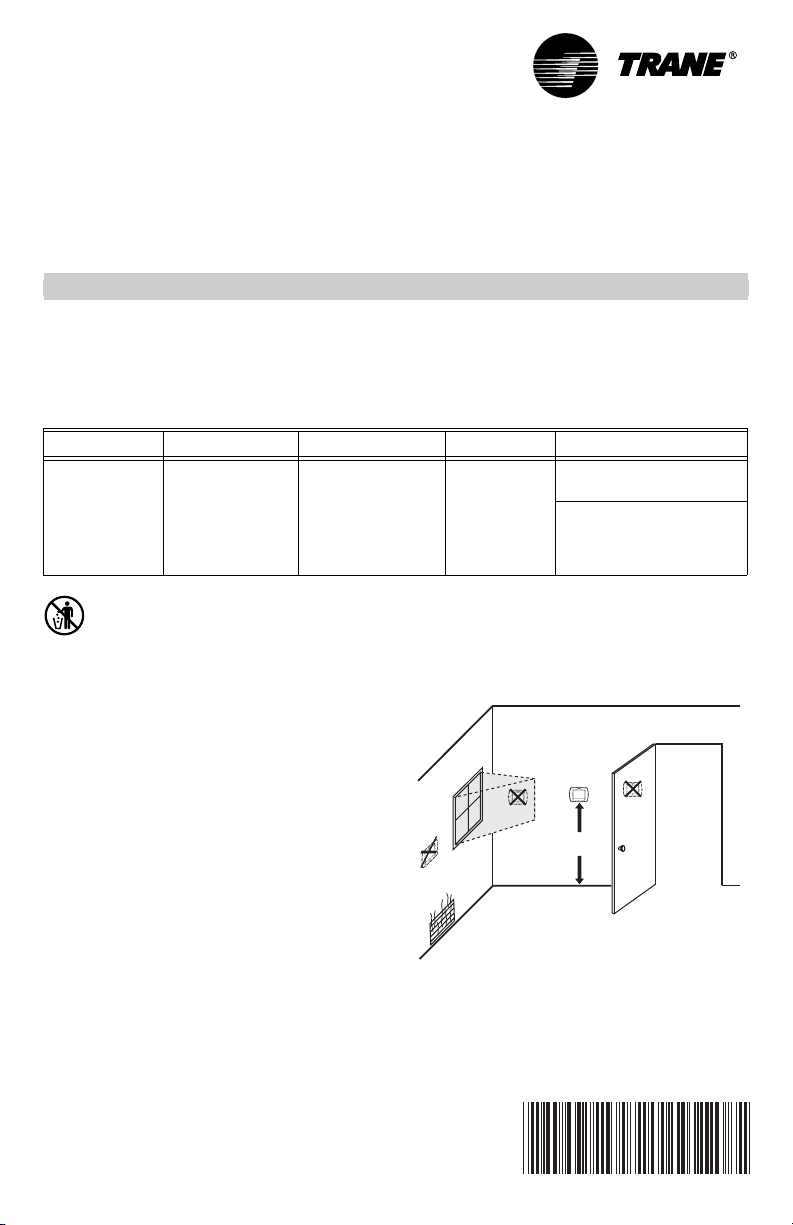
Selecting Location
Install the comfort control about 5 ft. (1.5m) above the
floor in an area with good air circulation at average
temperature. See Fig. 1.
INSTALLATION
When Installing this Product...
1. Read these instructions carefully. Failure to follow
the instructions can damage the product or cause
a hazardous condition.
2. Installer must be a trained, experienced service
technician.
3. After completing installation, use these instructions
to check out the product operation.
U.S. Pat. No. 6595430, D509151, and Other Patents Pending
NO
YES
NO
NO
Fig. 1. Selecting comfort control location.
5 FEET
[1.5 METERS]
M19925
69-1790-3
Page 2
TCONT802AS32DA TOUCH SCREEN AND TCONT803AS32DA TOUCH SCREEN WITH DEHUMIDIFICATION
/COOL
SC
S
P
S1
S2
C
G
Do not install the comfort control where it can be affected
by:
— Drafts or dead spots behind doors and in corners.
— Hot or cold air from ducts.
— Radiant heat from sun or appliances.
— Concealed pipes and chimneys.
— Unheated (uncooled) areas such as an outside wall
behind the comfort control.
Installing Wallplate
CAUTION
Electrical Hazard.
Can cause electrical shock or equipment
damage.
Disconnect power before wiring.
The comfort control can be mounted horizontally on the
wall or on a 4 in. x 2 in. (101.6 mm x 50.8 mm) wiring box.
1. Position and level the wallplate (for appearance
only).
2. Use a pencil to mark the mounting holes.
WALL
WIRES THROUGH WALL
AND WIRE SLOT
WALL ANCHORS (2)
MOUNTING
HOLES
MOUNTING
SCREWS (2)
Fig. 2. Mounting wallplate.
3. Remove the wallplate from the wall and, if drywall,
drill two 3/16-in. holes in the wall, as marked. For
firmer material such as plaster, drill two 7/32-in.
holes. Gently tap anchors (provided) into the drilled
holes until flush with the wall.
4. Position the wallplate over the holes, pulling wires
through the wiring opening. See Fig. 2.
5. Insert mounting screws into the holes and tighten.
M19916
3. Securely tighten each screw.
4. Push excess wire back into the hole.
5. Plug the hole with nonflammable insulation to pre-
vent drafts from affecting the comfort control.
HEAT PUM
HEAT
Y2
F
X2
W1
S1
S2
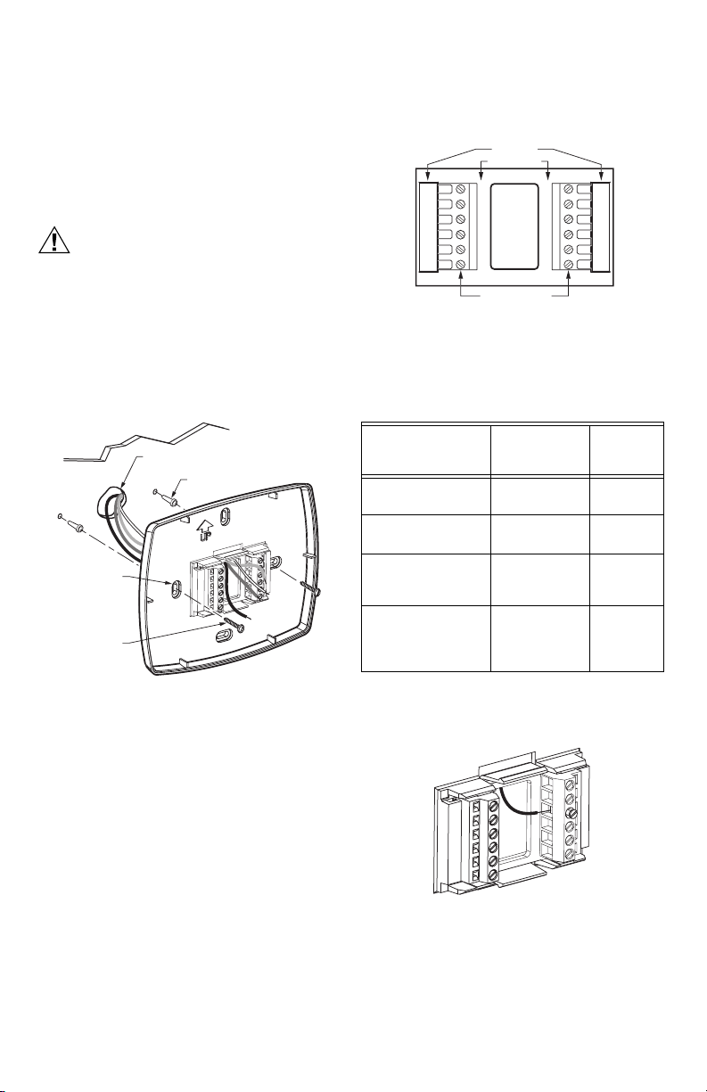
Fig. 3. Selecting terminal identifications for
Table 2. Selecting Terminal Identifications for
W2
system type.
System Type.
System Type
R
W1
REW TERMINAL
Wallplate
Ter mi nal
Identifications
Standard Heat/Cool Heat/Cool Fig. 5,
Standard Multistage
up to 2 Heat/2 Cool
Heat Pump with
Electric Auxiliary
(Backup) Heat
Heat Pump with
Fossil Fuel Auxiliary
(Dual Fuel) Heat
NOTE: The factory default setting is configured for a
1 Heat/1 Cool System with a gas furnace.
Heat/Cool Fig. 7,
Heat Pump Fig. 9,
Heat Pump Fig. 12,
RC
R
O
Y
Y
G
B
M22636
Wiring
Diagram
Reference
Fig. 6
Fig. 8
Fig. 10,
Fig. 11
Fig. 13,
Fig. 14,
Fig. 15
WIRING (FIG. 5-15)
All wiring must comply with local electrical codes and
ordinances.
1. Select set of terminal identifications (Table 2) that
corresponds with system type (heat/cool or heat
pump in Fig. 3).
2. Loosen the screws for the appropriate system type
selected; see Table 2. Insert wires in the terminal
block under the loosened screw. See Fig. 4.
Pub. No. 18-HD25D19-3
69-1790—3 2
Fig. 4. Inserting wires in terminal block.
IMPORTANT
Use 18 gauge comfort control wire.
M19917
Page 3
TCONT802AS32DA TOUCH SCREEN AND TCONT803AS32DA TOUCH SCREEN WITH DEHUMIDIFICATION
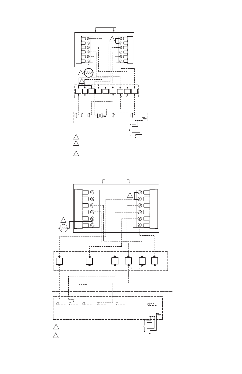
HEAT/COOL
Y2
W2
S1
S2
T
2
GYR
W1
INDOOR
OUTDOOR
ODT
Y
TO POWER SUPPLY
PER LOCAL CODES
FACTORY INSTALLED JUMPER.
1
OPTIONAL OUTDOOR OR INDOOR REMOTE SENSOR. AVAILABLE
2
ON SELECT MODELS. WIRES MUST HAVE A CABLE SEPARATE
FROM THE THERMOSTAT CABLE.
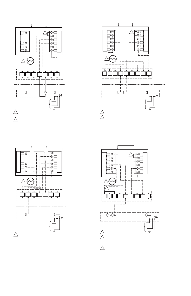
Fig. 5. Typical hookup of single-stage heat and cool
system with single transformer (1H/1C).
Y2
W2
S1
S2
T
1
GYR
T
OIL BURNER PRIMARY
INDOOR
OUTDOOR
Y
TO POWER SUPPLY
PER LOCAL CODES
OPTIONAL OUTDOOR OR INDOOR REMOTE SENSOR. AVAILABLE
1
ON SELECT MODELS. WIRES MUST HAVE A CABLE SEPARATE
FROM THE THERMOSTAT CABLE.
Fig. 6. Typical hookup of single-stage heat and cool
system with two transformers (1H/1C).
1
W2
T
W3
B/C
B
(3 PH
ONLY)
HEAT/COOL
W
B/C
B
(3 PH
ONLY)
RC
R
W1
Y
G
B
RC
R
W1
Y
G
B
AIR
HANDLER
COOLING UNIT
O.D. SECTION
(SINGLE STAGE)
OIL
FURNACE
COOLING UNIT
O.D. SECTION
(SINGLE STAGE)
M22637
M22638
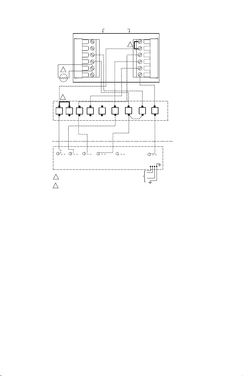
HEAT/COOL
Y2
W2
S1
S2
T
2
O
LO
BKR
Y
Y
Y2
Y1
TO POWER SUPPLY
PER LOCAL CODES
FACTORY INSTALLED JUMPER.
1
2
OPTIONAL OUTDOOR OR INDOOR REMOTE SENSOR. AVAILABLE
ON SELECT MODELS. WIRES MUST HAVE A CABLE SEPARATE
FROM THE THERMOSTAT CABLE.
Fig. 7. Typical hookup of two-stage indoor and
two-stage cooling unit in a single transformer system
Y2
W2
S1
S2
1
2
3
Fig. 8. Typical hookup of two-stage indoor and
two-step scroll cooling unit in a single transformer
(2H/2C or 2H/1C or 1H/2C).
T
2
3
O
BK R
Y2
FACTORY INSTALLED JUMPER.
OPTIONAL OUTDOOR OR INDOOR REMOTE SENSOR. AVAILABLE
ON SELECT MODELS. WIRES MUST HAVE A CABLE SEPARATE
FROM THE THERMOSTAT CABLE.
THE INSTALLER MUST JUMPER AT THE LVTB “R” TO “O”.
LO
Y
Y1
Y
TO POWER SUPPLY
PER LOCAL CODES
system (2H/2C or 2H/1C or 1H/2C).
1
G
W1
INDOOR
OUTDOOR
HEAT/COOL
1
W1
G
W2
RC
R
W1
Y
G
B
B/C
W2
B
(3 PH
ONLY)
RC
R
W1
Y
G
B
B/C
B
(3 PH
ONLY)
VARIABLE SPEED
TWO-STAGE
FURNACE/VARIABLE
SPEED AIR HANDLER
COOLING UNIT
O.D. SECTION
(TWO STAGE)
M22640
VARIABLE SPEED
TWO STAGE
FURNACE
INDOOR
OUTDOOR
16 SEER
COOLING UNIT
O.D. SECTION
(TWO STEP)
M24231
3 69-1790—3
Pub. No. 18-HD25D19-3
Page 4
TCONT802AS32DA TOUCH SCREEN AND TCONT803AS32DA TOUCH SCREEN WITH DEHUMIDIFICATION
HEAT PUMP
Y2
F
X2
W1
S1
S2
T
2
O
GYR
W1
ODT-1
ODT-2
INDOOR
OUTDOOR
O
Y
R
FACTORY INSTALLED JUMPER.
1
2
OPTIONAL OUTDOOR OR INDOOR REMOTE SENSOR. AVAILABLE
ON SELECT MODELS. WIRES MUST HAVE A CABLE SEPARATE
FROM THE THERMOSTAT CABLE.
1
W2
RC
R
O
Y
G
B
I-PF
SUPPL. HTR.
CONTROL BOX
W3
TO POWER
SUPPLY PER
LOCAL
CODES AND
AS DEFINED
IN FIELD
WIRING TABLE
BR(T)X2/BK
TO POWER SUPPLY
PER LOCAL CODES
PM-A
REQ.
FOR
3 PH
AIR
B/C
T
HANDLER
HEAT PUMP
O.D. SECTION
B
(SINGLE STAGE)
(3 PH
ONLY)
M22641
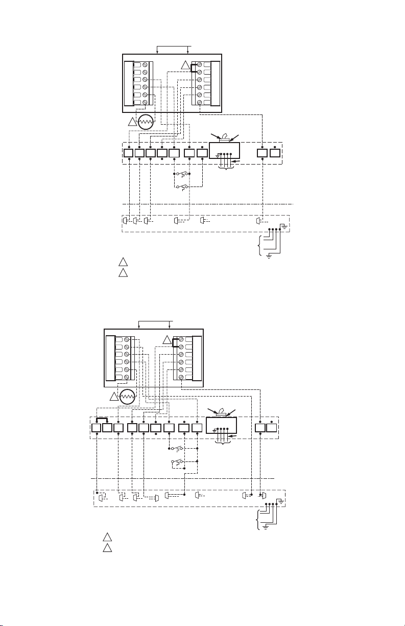
Fig. 9. Typical hookup of single-stage heat pump with auxiliary/backup heat (2H/1C heat pump).
HEAT PUMP
Y2
F
X2
W1
S1
S2
T
2
BK
YLO
OYR
G
INDOOR
OUTDOOR
Y2
O
R
1
2
Y1
FACTORY INSTALLED JUMPER.
OPTIONAL OUTDOOR OR INDOOR REMOTE SENSOR. AVAILABLE ON SELECT MODELS.
WIRES MUST HAVE A CABLE SEPARATE FROM THE THERMOSTAT CABLE.
1
W1
ODT-1
ODT-2
X2/BK
RC
R
O
Y
G
B
I-PF
PM-A
SUPPL. HTR.
CONTROL BOX
W3
W2
WIRING TABLE
BR(T)
REQ.
FOR
3 PH
TO POWER
SUPPLY PER
LOCAL
CODES AND
AS DEFINED
IN FIELD
TO POWER SUPPLY
PER LOCAL CODES
F
VARIABLE
B/C
T
SPEED AIR
HANDLER
HEAT PUMP
O.D. SECTION
B
(TWO STAGE)
(3 PH
ONLY)
M22642
Fig. 10. Typical hookup of multistage heat pump with auxiliary/backup heat (3H/2C heat pump).
Pub. No. 18-HD25D19-3
69-1790—3 4
Page 5
TCONT802AS32DA TOUCH SCREEN AND TCONT803AS32DA TOUCH SCREEN WITH DEHUMIDIFICATION
HEAT PUMP
Y2
F
X2
W1
S1
S2
T
2
3
O
BK R
G
LO
Y
Y2
Y1
O
R
FACTORY INSTALLED JUMPER.
1
2
OUTDOOR REMOTE SENSOR. WIRES MUST HAVE A CABLE
SEPARATE FROM THE THERMOSTAT CABLE.
THE INSTALLER MUST JUMPER AT THE LVTB “R” TO “O”.
3
X2/BK
TO POWER SUPPLY
PER LOCAL CODES
1
Y
BR(T)
W1
W2
RC
R
O
Y
G
B
VARIABLE SPEED
B/C
AIR HANDLER
INDOOR
OUTDOOR
B
(3 PH
ONLY)
16 SEER
HEAT PUMP
O.D. SECTION
(TWO STEP)
M24230
Fig. 11. Typical hookup of multistage two-step scroll heat pump with auxiliary/backup heat (3H/2C heat pump).
HEAT PUMP
Y2
F
X2
W1
S1
2
S2
T
1
RC
R
O
Y
G
B
NON-V.S.
ONE OR TWO
R
R O BR(T)X2/BK
1
FACTORY INSTALLED JUMPER.
OUTDOOR REMOTE SENSOR. WIRES MUST HAVE A
2
CABLE SEPARATE FROM THE THERMOSTAT CABLE.
G
Y
Y
W1
INDOOR
OUTDOOR
TO POWER SUPPLY
PER LOCAL CODES
W2
(3 PH
ONLY)
M24200
B/C
B
STAGE GAS
FURNACE
HEAT PUMP
O.D. SECTION
(SINGLE STAGE)
Fig. 12. Typical hookup of singe-stage heat pump with non-variable speed gas furnace.
5 69-1790—3
Pub. No. 18-HD25D19-3
Page 6
TCONT802AS32DA TOUCH SCREEN AND TCONT803AS32DA TOUCH SCREEN WITH DEHUMIDIFICATION
HEAT PUMP
(3 PH
ONLY)
M24201
RC
R
O
Y
G
B
B
VARIABLE
SPEED
TWO STAGE
FURNACE
HEAT PUMP
O.D. SECTION
(SINGLE STAGE)
Y2
F
X2
W1
S1
2
S2
T
1
O
R
BK
R O BR(T)BR/X2
1
FACTORY INSTALLED JUMPER.
OUTDOOR REMOTE SENSOR. WIRES MUST HAVE A
2
CABLE SEPARATE FROM THE THERMOSTAT CABLE.
Fig. 13. Typical hookup of single-stage heat pump with two stage variable speed gas furnace
G
Y
LO
Y
OR BK
(2H/1C heat pump).
1
W1 W2
YB/C
INDOOR
OUTDOOR
TO POWER SUPPLY
PER LOCAL CODES
Pub. No. 18-HD25D19-3
69-1790—3 6
Page 7

TCONT802AS32DA TOUCH SCREEN AND TCONT803AS32DA TOUCH SCREEN WITH DEHUMIDIFICATION
HEAT PUMP
Y2
F
X2
W1
S1
2
S2
T
1
Y
1/
O
R
BK
Y2
R O BR(T)X2/BK
1
FACTORY INSTALLED JUMPER.
OUTDOOR REMOTE SENSOR. WIRES MUST HAVE A
2
CABLE SEPARATE FROM THE THERMOSTAT CABLE.
G
Y1
Y/Y2 B/C
Y
LO
1
W1 W2
INDOOR
OUTDOOR
TO POWER SUPPLY
PER LOCAL CODES
RC
R
O
Y
G
B
VARIABLE
SPEED
TWO STAGE
FURNACE
F
(3 PH
ONLY)
M24202
HEAT PUMP
B
O.D. SECTION
(TWO STAGE)
Fig. 14. Typical hookup of multistage heat pump with two stage variable speed gas furnace (3H/2C heat pump).
7 69-1790—3
Pub. No. 18-HD25D19-3
Page 8

TCONT802AS32DA TOUCH SCREEN AND TCONT803AS32DA TOUCH SCREEN WITH DEHUMIDIFICATION
HEAT PUMP
(3 PH
ONLY)
M24203
RC
R
O
Y
G
B
VARIABLE
SPEED
TWO STAGE
FURNACE
B
16 SEER
HEAT PUMP
O.D. SECTION
(TWO STEP)
Y2
F
X2
W1
S1
2
S2
T
1
O
R
BK
3
Y2
R O BR(T)X2/BK
1
FACTORY INSTALLED JUMPER.
OUTDOOR REMOTE SENSOR. WIRES MUST HAVE A
2
CABLE SEPARATE FROM THE THERMOSTAT CABLE.
3
REMOVE / CUT JUMPER FROM R TO BK.
Fig. 15. Typical hookup of multistage two-step scroll heat pump with two stage variable speed gas furnace
G
Y
LO
Y1
(3H/2C heat pump).
1
W1 W2
YB/C
INDOOR
OUTDOOR
TO POWER SUPPLY
PER LOCAL CODES
Powering the Comfort Control
The Comfort Control can be powered with 24 Vac.
24 Vac Common Power (Recommended)
Wire the common side of the transformer to the B screw
of the comfort control wallplate. When installing in a single
transformer system, keep the jumper wire between the R
and Rc screws. When installing in a two-transformer
system, use the common from the cooling transformer to
connect to the B screw and remove the jumper wire
between the R and Rc screws.
Battery Power (Optional)
CAUTION
Equipment or Property Damage Hazard.
Using battery power only may not provide
adequate power to comfort control and can
cause damage during freezing conditions.
Connect the 24 Vac Common (B) wire from the
system transformer to the comfort control for
proper operation when the battery power is
drained.
Pub. No. 18-HD25D19-3
69-1790—3 8
Three AAA alkaline batteries can be used to power the
comfort control for armchair programming only. To prevent
the comfort control and heating/cooling system from
shutting down due to lack of battery power, it is not
recommended that the comfort control be solely powered
with the three AAA batteries during normal system
operation. When using batteries, make sure positive and
negative terminals are oriented correctly, as marked on
the device. See Fig. 16.
BATTERIES (3)
M19918
Fig. 16. Installing batteries on comfort control back.
Page 9

TCONT802AS32DA TOUCH SCREEN AND TCONT803AS32DA TOUCH SCREEN WITH DEHUMIDIFICATION
E
MON
UE
THUSASUN
E
MON
THUSASUN
CHANGE FILTER UV LAMP HUMIDIFIER PAD
OK TO PICK MULTIPLE DAYS SCREEN LOCKED
US
E
R
U
Mounting the Comfort Control
1. Align the terminal screw blocks with the pins on the
back of the comfort control.
2. Push the comfort control straight onto the wallplate.
See Fig. 17.
WALL
INSTALLATION
REMOVE DURING
M22643
Fig. 17. Mounting comfort control on wallplate.
Adjusting Real-Time Clock
Setting Calendar and Time
Locate and remove the tab labeled Remove in the lower
left corner on the comfort control back. The tab must be
removed to activate the real-time clock. See Fig. 18.
REMOVE TAB TO ACTIVATE REAL TIME CLOCK
INSTALLATION
REMOVE DURING
INSTALLATION
REMOVE DURING
M22644
Fig. 18. Removing tab to activate real-time clock.
This comfort control is designed to automatically keep the
current time and day in memory for up to ten years under
normal use once the calendar is set. When the comfort
control is first powered, the display is ready for the
calendar date to be entered. See Fig. 19.
SET CURRENT DAY
SET MONTH
T
DON
E ARROWS TO SET YEAR AND TIM
DON
M22645
Fig. 19. Setting calendar and time after initial
IMPORTANT
The tab on the back of the comfort control in the
lower left corner must be removed for this
feature to be active.
powerup.
Using the Comfort Control
The comfort control has a touch screen interface. Words
or symbols appear, highlighting the keys, as necessary, to
complete tasks. Always press the keys with your
fingertips. Sharp instruments like a pen or pencil point can
damage the comfort control.
1. Use the arrow keys to set the Year, Month and Day,
as shown in Fig. 19.
2. Press the Done key.
3. Use the arrow keys to set the current time. See
Fig. 19.
4. Press the Done key.
9 69-1790—3
Pub. No. 18-HD25D19-3
Page 10

TCONT802AS32DA TOUCH SCREEN AND TCONT803AS32DA TOUCH SCREEN WITH DEHUMIDIFICATION
OPERATION
78°F
(25.5°C)
85°F
(29.5°C)
78°F
(25.5°C)
82°F
(28°C)
TO C
M22646
SettingHeat Cool
Auto
Auto
Auto
Auto
System and Fan Settings
The System default setting is Heat and the Fan default
setting is Auto.
SYSTEM SETTINGS
Heat: controls heating system.
Off: heating and cooling are off.
Cool: controls cooling system.
Auto: automatically changes between heating and cooling
systems, depending on indoor temperature. (See Installer
Setup section.)
Em Heat: emergency heat cycles to maintain
temperature. Compressor is locked out. (Used only for
heat pump systems with backup heat.)
FAN SETTINGS
The Fan setting can be programmed into the comfort
control schedule for each period (Wake, Leave, Return,
Sleep). See the Owners’ Guide for additional information.
LED Indication (Requires 24 Vac Common
Connection)
An LED indicator is located in the upper right corner of the
comfort control. It is only visible when lighted:
• It indicates when the comfort control is in the
Emergency Heat mode. When in Em. Ht. mode, the F
terminal is continuously energized and the LED is on.
• When the F terminal is wired to an equipment monitor,
the LED signals when a check or fail signal is sent to
the comfort control from the system. See Fig. 20. (This
can occur only when the comfort control is not in Em.
Ht. mode.)
C
EQUIPMENT
MONITOR
FTO R
Fig. 20. F terminal switch to R (power) side of system
Preprogrammed Settings
Table 3 shows the default program settings. See Owners’
Guide for complete instructions on changing the program.
transformer.
Table 3. Default Program Settings.
Schedule
Period Time
Wake 6:00AM 70°F
Leave 8:00AM 62°F
Return 6:00PM 70°F
Sleep 10:00PM 62°F
Setpoints
(21°C)
(16.5°C)
(21°C)
(16.5°C)
Fan
Pub. No. 18-HD25D19-3
69-1790—3 10
Page 11

TCONT802AS32DA TOUCH SCREEN AND TCONT803AS32DA TOUCH SCREEN WITH DEHUMIDIFICATION
E
MO
USASU
SYSTE
M
OFF
g
Schedule
de
Se
o
E
DONE
MON
THUSASUN
A
INSTALLER SETUP
The comfort control works with many different system
types. To operate correctly, the comfort control must be
set up to operate the installed heating and/or cooling
system.
Follow these steps to enter the Installer Setup:
1. Be sure the comfort control is powered.
2. Press and release the System Key.
FAN
ON
AUTO
SYSTEM
EM HEAT
OFF
COOL
3. Press and hold the two blank keys on either side of
the center blank key for approximately five seconds
until screen changes.
THU
Inside
SCHED HOLD CLOCK SCREE
Insi
Set To
A
M
T
t T
Following
Schedule
Followin
M22647
4. Release the two blank keys when the screen on the
comfort control matches the screen below.
DON
M22649
5. See screen below to review how the comfort control
keys are used during Installer Setup. See Table 4
for the Installer Setup Numbers and Settings.
ADVANCE TO NEXT
INSTALLER
SETUP
NUMBER
INSTALLER SETUP
CURRENT
SETTING
DON
CANC
M22648
PRESS TO EXIT
INSTALLER SETUP
6. Press the Done key to exit the Installer Setup
screen.
11 69-1790—3
CHANGE THE
CURRENT
SETTING
M22650
Pub. No. 18-HD25D19-3
Page 12

TCONT802AS32DA TOUCH SCREEN AND TCONT803AS32DA TOUCH SCREEN WITH DEHUMIDIFICATION
IMPORTANT
The Installer Setup Menu (Table 4) shows all the available options. These options customize themselves as
you make selections to the Installer Setup. Therefore, not all Installer Setup Selections are shown or are available to change.
Table 4. Installer Setup Menu.
Factory Setting Other Choices
Installer
Select
Not used. 1 thru
Date (Year
Upper)
Date (Year
Lower)
Date (Month) 0140 6 Digit(s) represents
Date
(Day)
Schedule
Options
System Type
Selection
Fan Operation 0180 0 Heat/Cool
Backup Heat
Source
(Auxiliary
Heat)
External
Fossil Fuel Kit
Cycles per
hour (cph) for
1st Stage
Compressor
Cycles per
hour (cph) for
2nd Stage
Compressor
Setup
Number
0099
0120 20 Set first two digits of
0130 05 Represents last two
0150 15 Digit(s) represents
—— — — —
current calendar year
(20 for year 2005, etc)
digits of current
calendar year (2005).
current calendar
month.
current calendar date.
21 21 —first two digits of current
calendar year (21xx)
00 -99 Select last two digits of current
calendar year.
1-12 Select number that represents
current calendar month.
1-31 Select number that represents
current calendar date.
CommentsOption Description Options Description
2000 - 2178 available
2000 - 2178 available
—
0160 4 7-day programming 0 0—nonprogrammable —
0170 1 1 Heat/1Cool 1-12 1—1heat/1cool
applications where
equipment controls
fan operation in heat
0200 0 Heat pump backup
0210 1 External fossil fuel kit
0220 3 Compressor Stage 1
0230 3 Compressor Stage 2
mode.
heat source is electric.
is controlling heat
pump backup heat
(recommended)
cycles per hour (cph)
cycles per hour (cph)
2—single-stage heat pump (no
aux. heat)
3—heat only (no fan)
4—heat only (with fan)
5—hot water Series 20 (3-wire
or normally open zone valves)
6—cool only
7—2 heat/1cool heat pump
8—2 heat/2 cool
9—2 heat/1cool
10—1 heat/2 cool oil furnace
or 0H/2C
11—2 heat/2 cool heat pump
(with no auxiliary heat)
12—3 heat/2 cool heat pump
(with auxiliary heat)
1 Heat pump or electric heat
applications where comfort
control controls fan operation
in heat mode.
1 Heat pump backup heat
source is fossil fuel.
0 No external fossil fuel kit is
controlling heat pump backup
heat. This comfort control
controls the backup fossil fuel
heat with outdoor sensor.
1-6 1-6 available;
3 is recommended.
1-6 1-6 available;
3 is recommended.
Available options and
defaults vary by
comfort control.
System selection
automatically
modifies some
default settings and/
or hides other
Installer Setup
options.
Only shown if heat/
cool system is
selected. If heat
pump is chosen, fan
defaults to electric.
Only shown if 2 heat/
1 cool or 3 heat/2
cool heat pump is
chosen.
Only shown if fossil
fuel is chosen as
backup heat source.
Only shown if two
stages of cool are
selected.
—
—
Pub. No. 18-HD25D19-3
69-1790—3 12
Page 13

TCONT802AS32DA TOUCH SCREEN AND TCONT803AS32DA TOUCH SCREEN WITH DEHUMIDIFICATION
Table 4. Installer Setup Menu. (Continued)
Factory Setting Other Choices
Installer
Select
Cycles per
hour (cph) for
1st Stage
Heat
Cycles per
hour (cph) for
2nd Stage
Heat
Cycles per
hour (cph) for
3rd Stage
Heat
Cycles per
hour (cph) for
Em Heat
Continuous
Backlight
Setup
Number
0240 5 Heat Stage 1 cycles
0250 5 Cycles per hour (cph)
0260 9 Cycles per hour (cph)
0270 9 Cycles per hour (cph)
0280 0 Backlight not on
per hour (cph)
for 2nd Stage Heat or
Auxiliary Heat for
2 H/1C Heat Pump
Systems
for Auxiliary Heat in
3H/2C Heat Pump
Systems
for Emergency Heat
continuously. Comfort
control backlight
comes on with each
key press.
1-12 1-12 available; typical settings:
1—1 cph used for steam or
gravity system.
3—3 cph used for 2-stage
fossil fuel forced air systems or
hot water systems.
5—5 cph used for single-stage
fossil fuel forced air systems.
9—9 cph used for electric
forced air heat systems
(electric auxiliary heat for heat
pump systems).
1-12 1-12 available; typical settings:
1—1cph used for steam or
gravity system.
3—3 cph used for 2-stage
fossil fuel forced air systems or
hot water systems.
5—5 cph used for single-stage
fossil fuel forced air systems.
9—9 cph used for electric
forced air heat systems
(electric auxiliary heat for heat
pump systems).
1-12 1-12 is available; typical
settings:
3—3 cph used for 2-stage
fossil fuel forced air systems or
hot water systems.
5—5 cph used for single-stage
fossil fuel forced air systems.
9—9 cph used for electric
forced air heat systems
(electric auxiliary heat for heat
pump systems).
1 Backlight is on continuously
(comfort control must have a
common wire attached for this
function).
CommentsOption Description Options Description
Not shown if system
selection is heat
pump. Selection in
this stage changes
default cph for 2nd
stage heat.
Only shown if two
stages of heat are
selected.
Only shown if 3H/2C
heat pump system is
selected.
Only shown if 2 heat/
1 cool or 3 heat/2
cool heat pump is
selected.
Option is always
shown; however,
continuously on
backlight works only if
comfort control is
wired with 24 Vac
Common.
Changeover 0300 0 Manual changeover 1 1—auto changeover —
13 69-1790—3
Pub. No. 18-HD25D19-3
Page 14

TCONT802AS32DA TOUCH SCREEN AND TCONT803AS32DA TOUCH SCREEN WITH DEHUMIDIFICATION
Table 4. Installer Setup Menu. (Continued)
Factory Setting Other Choices
Installer
Select
Deadband 0310 2 thru 9 Heating and cooling
Temperature
Indication
Scale
Daylight
Savings
Remote
Temperature
Sensor
(Outdoor or
Indoor)
Heat Pump
Compressor
Lockout
Setup
Number
setpoints can be set
no closer than chosen
value:
2—2°F (1°C)
3—3°F (2°C)
4—4°F (2.5°C)
5—5°F (3°C)
6—6°F (3.5°C)
7—7°F (4°C)
8—8°F (4.5°C)
9—9°F (5°C)
0320 0 Temperature is
0330 1 Daylight savings
0340 0 No remote
0350 0 No compressor
displayed in °F.
enabled (use through
2006 and for areas
that do not
new 2007 DST
calendar).
use the
temperature sensor
lockout.
3 Heating and cooling setpoints
can be set no closer than 3°F
(1.5°C).
Shown only if
automatic
changeover is
selected.
The deadband is
restricted to the range
of 5 to 9 if ISU 0380 is
set to
dehumidification
droop control.
1 Temperature is displayed in °C. —
CommentsOption Description Options Description
0, 2 0—daylight savings is
disabled.
2—daylight savings is enabled
(start using in 2007, for areas
that use the new 2007 DST
calendar).
1-3 1—outdoor temperature
sensor for display only.
2—outdoor temperature
sensor for system control,
used for select heat pump
systems. (See Special Heat
Pump Features section for
more details.)
3—indoor temperature sensor
15, 20,
15°F (-9.5°C)
25, 30,
20°F (-6.5°C)
35, 40,
25°F (-4°C)
45
30°F (-1°C)
35°F (1.5°C)
40°F (4.5°C)
45°F (7°C)
Set to 0 in areas that
do not follow daylight
savings.
Defaults and Options
depend on System
Type selection.
Indoor Temperature
Sensor uses an
averaging network
and does not include
on-board sensor.
Default depends on
other selections.
Shown if Outdoor
Temperature for
control is selected.
Heat Pump
Auxiliary
Lockout
Indoor
Dehumidification Control
Furnace Filter
Change
Reminder
Humidifier
Pad
Replacement
Reminder
Pub. No. 18-HD25D19-3
69-1790—3 14
0360 0 No heat pump
0380 0 No indoor
0500 0 Furnace filter change
0510 0 Humidifier pad
auxiliary lockout.
dehumidification
control.
reminder off.
replacement reminder
off.
40, 45,
50, 55,
60
1 1—dehumidification droop
1-6 1—10 run time days
1-3 1—90 calendar days
40°F (4.5°C)
45°F (7°C)
50°F (10°C)
55°F (13°C)
60°F (15.5°C
control.
2—30 run time days
3—60 run time days
4—90 run time days
5—120 run time days
6—365 run time days
2—180 calendar days
3—365 calendar days
Shown if electric is
chosen for backup
heat source and
outdoor temperature
sensor for control is
selected.
Available on models
with humidity sensor.
Run time based on
call for fan.
—
Page 15

TCONT802AS32DA TOUCH SCREEN AND TCONT803AS32DA TOUCH SCREEN WITH DEHUMIDIFICATION
Table 4. Installer Setup Menu. (Continued)
Factory Setting Other Choices
Installer
Select
Adaptive
Intelligent
Recovery™
Number of
Periods
Minimum
Compressor
Off Time
Heat
Temperature
Range Stop
Cool
Temperature
Range Stop
Setup
Number
0530 1 Adaptive Intelligent
0540 4 Four periods available
0580 5 Five minute minimum
0600 90 Highest heating
0610 50 Lowest cooling
Recovery™ control is
activated (system
starts early so setpoint
is reached by start of
program period).
(Wake, Leave, Return,
Sleep)
off time for
compressor.
setpoint.
setpoint.
0 0—conventional recovery
(system starts recovery at
programmed time)
2 Two periods available (Wake
and Sleep)
0, 2, 3, 4Minimum number of minutes
compressor is off between
calls for compressor.
40 to 89 Temperature range (1°F
increments) of heating
setpoint.
51 to 99 Temperature range (1°F
increments) of cooling
setpoint.
CommentsOption Description Options Description
Not shown if
non-programmable is
selected. 2 or 4
applies to all days of
the week.
Five minutes
recommended
Shown in 1/2 °C.
Shown in 1/2 °C.
Clock Format 0640 12 12-hour clock format 24 24-hour clock format —
Extended Fan
on time Heat
Extended Fan
on time Cool
Keypad
Lockout
0650 0 No extended fan
0660 0 No extended fan
operation after call for
heat ends.
operation after call for
cool ends.
0670 0 Unlocked keypad 1, 2 1—partially locked keypad
90 Fan operation is extended 90
seconds after call for heat
ends.
90 Fan operation is extended 90
seconds after call for cool
ends.
2—fully locked keypad
Not shown if fan
operation is set to
fossil fuel or in Cool
Only Systems
Not shown in Heat
Only Systems.
Unlocked—all
functions are
available.
Partially locked—only
temperature up and
down keys and ability
to enter and modify
Installer Setup mode
are available. Fully
locked—only ability to
enter and modify
Installer Setup mode
are available.
—
15 69-1790—3
Pub. No. 18-HD25D19-3
Page 16

TCONT802AS32DA TOUCH SCREEN AND TCONT803AS32DA TOUCH SCREEN WITH DEHUMIDIFICATION
Table 4. Installer Setup Menu. (Continued)
Factory Setting Other Choices
Installer
Select
Temperature
Control in
Heat
Temperature
Control in
Cool
Temperature
Display Offset
Reset Comfort
Control
Setup
Number
0680 2 Standard temperature
0690 2 Standard temperature
0700 0 No difference in
0710 0 No comfort control
control in heating.
control in cooling.
displayed temperature
and actual room
temperature.
reset.
1, 3 1—less aggressive
temperature control (could
cause temperature
undershoot)
3—more aggressive
temperature control (could
cause temperature overshoot)
1, 3 1—less aggressive
temperature control (could
cause temperature
undershoot)
3—more aggressive
temperature control (could
cause temperature overshoot)
-3, -2,
-3°F (-1.5°C)
-1, 0, 1,
-2°F (-1°C)
2, 3
-1°F (-0.5°C)
0°F (0°C)
1°F (0.5°C)
2°F (1°C)
3°F (1.5°C)
1 Resets all Installer Setup
Options to default values and
resets schedule to default
setting.
CommentsOption Description Options Description
Applies to recovery
ramp and use of
auxiliary heat during
recovery.
Choose 1 if getting
temperature
overshoot.
Choose 3 if getting
temperature
undershoot.
Applies to recovery
ramp.
Choose 1 if getting
temperature
overshoot.
Choose 3 if getting
temperature
undershoot.
—
Only calendar
settings and time are
retained.
Pub. No. 18-HD25D19-3
69-1790—3 16
Page 17

TCONT802AS32DA TOUCH SCREEN AND TCONT803AS32DA TOUCH SCREEN WITH DEHUMIDIFICATION
SYSTEM CHECKOUT
Installer System Test
The Installer System Test mode is used to test the HVAC
system(s). See Table 5. While in System Test mode,
minimum off-time for compressors is bypassed.
The Installer Test is part of the Installer Setup options.
Enter Installer Setup screen and press the Down arrow
key to bring up test selection(s) quickly.
Table 5. System Test(s).
Select
Installer
Tes t C o o l
Installer
Tes t F a n
Installer
Tes t H e a t
Installer
Tes t E m
Ht
Installer
Setup
Number
Test 1 0 Cool is off 1,2 0—cool off
Test 2 0 Fan is off 1 0—fan off
Test 3 0 Heat is off 1-3 0—heat off
Test 4 0 Emergency
Factory Setting Other Choices
heat is off
CAUTION
Equipment Damage Hazard.
Minimum compressor off-time is bypassed
during Installer System Test.
Avoid cycling compressor quickly.
1—cool stage 1 turns on
2—cool stages 1 and 2 on
1—fan turns on
1—stage 1 heat on
2—stages 1 and 2 heat on
3—stages 1, 2 and 3 (Aux
Ht) on
1 0—emergency heat off
1—emergency heat on
2—emergency heat and
auxiliary heat turn on
CommentsOptions Description Options Description
System selection
determines which
tests are available
and the number of
stages shown.
—
—
Available only if
heat pump with
auxiliary heat is
selected.
17 69-1790—3
Pub. No. 18-HD25D19-3
Page 18

TCONT802AS32DA TOUCH SCREEN AND TCONT803AS32DA TOUCH SCREEN WITH DEHUMIDIFICATION
ADVANCED FEATURES
Outdoor or Indoor Temperature Sensor
For accuracy, the initial reading of the indoor and outdoor
temperature sensors require five minutes to stabilize. See
the Sensor instructions for installation information.
Special Heat Pump Features
Heat Pump with Fossil Fuel Auxiliary Heat (Dual
Fuel) and Outdoor Temperature Sensor
In this operation there is no external fossil fuel kit (dual
fuel kit) installed; the comfort control controls this function.
1. Choose correct heat pump application in Installer
Setup Number 0170.
2. Choose Fossil Fuel Option as the backup heat
source in Installer Setup Number 0200.
3. Choose No External Fossil Fuel Kit Option as
controlling backup heat in installer Setup Number
0210.
4. Outdoor Temperature Sensor for Control Option
is automatically chosen in Installer Setup Number
0340.
5. Choose appropriate Balance Point Temperature
in Installer Setup Number 0350.
OPERATION IN HEAT MODE ABOVE BALANCE POINT
(OUTDOOR TEMPERATURE)
When the outdoor temperature is above the selected
Balance Point Temperature (ISU 0350), only the
compressor operates and the fan (G terminal) energizes
when the comfort control calls for heat.
OPERATION IN HEAT MODE BELOW BALANCE POINT
(OUTDOOR TEMPERATURE)
When the outdoor temperature is below the selected
Balance Point Temperature (ISU 0350), only the Fossil
Fuel (auxiliary heat) operates and the fan (G terminal)
does not energize when the comfort control calls for heat.
OPERATION IN EMERGENCY HEAT MODE
The balance point (outside) temperature is not used in the
Emergency heat mode. When the comfort control is
moved to the Emergency Heat position, the compressor is
locked out. The first stage of heat is whatever is
connected to the X2 terminal. The second stage of heat is
what is connected to the W1 terminal. Often there is only
one source of non-compressor heat and the X2 terminal is
jumpered to the W1 terminal.
Heat Pump with Electric Auxiliary (Backup) Heat
and Outdoor Temperature Sensor
1. Choose correct heat pump application in Installer
Setup Number 0170.
2. Choose Electric as Auxiliary (Backup) Heat
Source in Installer Setup Number 0200.
3. Choose Outdoor Temperature Sensor for
Control Option in Installer Setup Number 0340.
4. Choose Compressor Lockout Temperature in
Installer Setup Number 0350.
5. Choose Auxiliary Lockout Temperature in
Installer Setup Number 0360.
NOTE: There is a 5°F deadband between the Compres-
sor and Auxiliary Heat Lockout Temperatures
OPERATION IN HEAT MODE
When the outdoor temperature is below the Compressor
Lockout Temperature, only the Auxiliary Heat operates.
When the outdoor temperature is above the Auxiliary
Lockout Temperature, only the Compressor operates.
See Fig. 21.
COMPRESSOR ONLY
50
BOTH COMPRESSOR AND
AUXILIARY HEAT
35
OUTDOOR TEMPERATURE
When the outdoor temperature is between the two
temperatures, both the Compressor and Auxiliary Heat
operate.
AUXILIARY ONLY
Fig. 21. Heat Pump Operation with Lockout
Temperatures Set.
AUXILIARY
LOCKOUT
TEMPERATURE
COMPRESSOR
LOCKOUT
TEMPERATURE
M19950
OPERATION IN THE EMERGENCY HEAT MODE
Once the comfort control is placed into the Emergency
Heat mode, the compressor and auxiliary lockout features
are turned off. In the Emergency heat mode, the
compressor is locked out. The first stage of heat is
whatever is connected to the X2 terminal. The second
stage of heat is connected to the W1 terminal. Usually the
emergency and auxiliary heat sources are electric strip
heat in these cases.
Dehumidification Droop Control
The dehumidification control attempts to control to the
user's humidity setpoint by turning on the air conditioner.
In extremely high humidity conditions, the comfort control
keeps the air conditioner running for up to 3
temperature setpoint. It does this while trying to achieve
the desired humidity setpoint and balancing that with the
temperature setpoint.
°
F below the
Pub. No. 18-HD25D19-3
69-1790—3 18
Page 19

TCONT802AS32DA TOUCH SCREEN AND TCONT803AS32DA TOUCH SCREEN WITH DEHUMIDIFICATION
TROUBLESHOOTING (SEE TABLE 6)
Table 6. Troubleshooting.
Symptom Possible Cause Action
Display does not come on. Comfort control is not being
Temperature settings do not
change.
Heating or cooling does not come
on.
Comfort control is calling for Heat
(Heat on) or Cool (Cool on) but no
heating or cooling is running.
Comfort control does not respond
when touch areas are pressed.
powered.
The upper or lower temperature
limits were reached.
The keypad is fully locked. Check Installer Setup Number 0670 to
Comfort control minimum offtime is activated.
System selection is not set to
Heat or Cool.
System type Selection is
incorrect.
Heating or cooling equipment is
not operating.
The keypad is locked. Check Installer Setup Number 0670 to
Check for 24 Vac between B and Rc.
Check temperature setpoints.
Check Installer Setup Numbers 0600 and
0610; modify as needed.
change keypad locked options.
Wait up to five minutes for the system to
respond.
Set system Selection to correct position.
Check Installer Setup Number 0170 and
make sure correct System type is
chosen.
Check wiring.
Check Installer Setup Number 0170 and
make sure correct system type is chosen.
Verify operation of equipment in System
Test mode.
change keypad locked options.
19 69-1790—3
Pub. No. 18-HD25D19-3
Page 20

TCONT802AS32DA TOUCH SCREEN AND TCONT803AS32DA TOUCH SCREEN WITH DEHUMIDIFICATION
® U.S. Registered Trademark
© 2006 American Standard Inc.
All Rights Reserved
Pub. No. 18-HD25D19-3
69-1790—3 M.S. Rev. 01-06
American Standard Inc.
Troup Highway
Tyler, TX 75711-9010
 Loading...