

Trane SEHJ090-162, SSHJ090-162, SFHJ090-162, SXHJ090-162, SLHJ090-162 Installation and Maintenance Manual
Page 1
Installation, Operation,
and Maintenance
IntelliPak™ II
Commercial Single-Zone Rooftop Air Conditioners
with CV, VAV, SZVAV, or RR Controls
“F0” and later design sequence
SEHJ090-162 SSHJ090-162
SFHJ090-162 SXHJ090-162
SLHJ090-162
SAFETY WARNING
Only qualified personnel should install and service the equipment. The installation, starting up, and servicing
of heating, ventilating, and air-conditioning equipment can be hazardous and requires specific knowledge and
training. Improperly installed, adjusted or altered equipment by an unqualified person could result in death or
serious injury.When working on the equipment, observe all precautions in the literature and on the tags,
stickers, and labels that are attached to the equipment.
November 2014
RT-SVX24K-EN
Page 2
Introduction
Read this manual thoroughly before operating or servicing
this unit.
Warnings, Cautions, and Notices
Safety advisories appear throughout this manual as
required.Your personal safety and the proper operation of
this machine depend upon the strict observance of these
precautions.
The three types of advisories are defined as follows:
WARNING
Proper Field Wiring and Grounding
Required!
Failure to follow code could result in death or serious
injury. All field wiring MUST be performed by qualified
personnel. Improperly installed and grounded field
wiring poses FIRE and ELECTROCUTION hazards. To
avoid these hazards, you MUST follow requirements for
field wiring installation and grounding as described in
NEC and your local/state electrical codes.
WARNING
CAUTIONs
NOTICE
Indicates a potentially hazardous
situation which, if not avoided, could
result in death or serious injury.
Indicates a potentially hazardous
situation which, if not avoided, could
result in minor or moderate injury. It
could also be used to alert against
unsafe practices.
Indicates a situation that could result in
equipment or property-damage only
accidents.
Important Environmental Concerns
Scientific research has shown that certain man-made
chemicals can affect the earth’s naturally occurring
stratospheric ozone layer when released to the
atmosphere. In particular, several of the identified
chemicals that may affect the ozone layer are refrigerants
that contain Chlorine, Fluorine and Carbon (CFCs) and
those containing Hydrogen, Chlorine, Fluorine and
Carbon (HCFCs). Not all refrigerants containing these
compounds have the same potential impact to the
environment.Trane advocates the responsible handling of
all refrigerants-including industry replacements for CFCs
such as HCFCs and HFCs.
Important Responsible Refrigerant
Practices
Trane believes that responsible refrigerant practices are
important to the environment, our customers, and the air
conditioning industry. All technicians who handle
refrigerants must be certified.The Federal Clean Air Act
(Section 608) sets forth the requirements for handling,
reclaiming, recovering and recycling of certain
refrigerants and the equipment that is used in these
service procedures. In addition, some states or
municipalities may have additional requirements that
must also be adhered to for responsible management of
refrigerants. Know the applicable laws and follow them.
WARNING
Personal Protective Equipment (PPE)
Required!
Installing/servicing this unit could result in exposure to
electrical, mechanical and chemical hazards.
• Before installing/servicing this unit, technicians
MUST put on all PPE required for the work being
undertaken (Examples; cut resistant gloves/sleeves,
butyl gloves, safety glasses, hard hat/bump cap, fall
protection, electrical PPE and arc flash clothing).
ALWAYS refer to appropriate Material Safety Data
Sheets (MSDS)/Safety Data Sheets (SDS) and OSHA
guidelines for proper PPE.
• When working with or around hazardous chemicals,
ALWAYS refer to the appropriate MSDS/SDS and
OSHA/GHS (Global Harmonized System of
Classification and Labelling of Chemicals) guidelines
for information on allowable personal exposure
levels, proper respiratory protection and handling
instructions.
• If there is a risk of energized electrical contact, arc, or
flash, technicians MUST put on all PPE in accordance
with OSHA, NFPA 70E, or other country-specific
requirements for arc flash protection, PRIOR to
servicing the unit. NEVER PERFORM ANY
SWITCHING, DISCONNECTING, OR VOLTAGE
TESTING WITHOUT PROPER ELECTRICAL PPE AND
ARC FLASH CLOTHING. ENSURE ELECTRICAL
METERS AND EQUIPMENT ARE PROPERLY RATED
FOR INTENDED VOLTAGE.
Failure to follow instructions could result in death or
serious injury.
About the Manual
Note: This document is customer property and must be
retained by the unit owner for use by maintenance
personnel.
These units are equipped with electronic Unit Control
Modules (UCM). Refer to the “Startup” and “Test Mode”
procedures within this Installation, Operation, and
© 2014Trane All rights reserved RT-SVX24K-EN
Page 3

Introduction
Maintenance manual and the latest edition of the
appropriate programming manual for Constant Volume
(CV), Rapid Restart (RR), Variable Air Volume (VAV), or
Single Zone Variable Air Volume (SZ VAV) applications
before attempting to operate or service this equipment.
Note: The procedures discussed in this manual should
only be performed by qualified and experienced
HVAC technicians.
Overview of Manual
This booklet describes proper installation, startup,
operation, and maintenance procedures for 90 to 162 ton
rooftop air conditioners designed for CV, RR, VAV, or SZ
VAV applications. By carefully reviewing the information
within this manual and following the instructions, the risk
of improper operation and/or component damage will be
minimized.
Note: One copy of the appropriate service literature ships
inside the control panel of each unit.
It is important that periodic maintenance be performed to
help assure trouble free operation. Should equipment
failure occur, contact a qualified service organization with
qualified, experienced HVAC technicians to properly
diagnose and repair this equipment.
Note: Do Not release refrigerant to the atmosphere!
If adding or removing refrigerant is required, the service
technician must comply with all federal, state, and local
laws.
Copyright
This document and the information in it are the property of
Trane, and may not be used or reproduced in whole or in
part without written permission. Trane reserves the right
to revise this publication at any time, and to make changes
to its content without obligation to notify any person of
such revision or change.
Trademarks
All trademarks referenced in this document are the
trademarks of their respective owners.
Revision History
RT-SVX24K-EN (November 2014)
Updated the IOM with Ultra-Low Leak, AMCA 1A damper
and FDD.These features are Design Specials only.
RT-SVX24K-EN 3
Page 4

Table of Contents
Introduction ............................. 2
Warnings, Cautions, and Notices ........ 2
Model Number Descriptions .............. 6
Unit Inspection .......................... 9
As soon as the unit arrives at the job site 9
Storage ............................ 9
Unit Clearances ..................... 9
Unit Dimensions and Weight Information 9
General Information .................... 10
Unit Nameplate ...................... 10
Commonly Used Acronyms ............ 10
Unit Description ...................... 10
Constant Volume (CV) and Variable Air
Volume (VAV) Units
................... 13
Constant Volume (CV) Units ........... 17
Variable Air Volume (VAV) Units ........ 17
Single Zone Variable Air Volume (SZVAV)
Only
................................ 20
Unit Clearances ......................... 23
Dimensional Data ....................... 25
Weights ................................ 44
Installation ............................. 47
Roof Curb and Ductwork ............. 47
Field Converting Horizontal Ductwork
(Supply or Return) from Right to
Left Side .......................... 49
Unit Rigging and Placement ........... 51
Air-Cooled and Evaporative Condensers—
Three-Piece Unit Fit Up .............. 54
Air-Cooled and Evaporative Condensers—
Two-Piece Unit Fit Up ............... 58
Complete Tubing and Wiring
Connections as follows: .............. 61
Air-Cooled Tubing Connection ........ 61
Evaporative Condenser Tubing
Connection ........................ 62
Electric Heat Wiring Connection ....... 63
Power and Control Wiring Connections . 63
General Unit Requirements ........... 64
Rigging the Unit .................... 65
Main Electrical Power Requirements ....65
Field Installed Control Wiring ..........65
Requirements for Electric Heat Units ....65
Requirement for Gas Heat .............65
Requirements for Hot Water Heat ......65
Requirements for Steam Heat ..........65
O/A Pressure Sensor and Tubing
Installation .........................65
Condensate Drain Connections ........65
Units with Gas Furnace ...............66
Removing Compressor Assembly
Shipping Hardware ..................66
Removing Supply and Exhaust Fan
Shipping Channels ...................66
Spring Isolators .....................66
Remove Evaporative Condenser Fan
Shipping Brackets ...................66
O/A Sensor and Tubing Installation .....68
Units with Statitrac: ..................68
Evaporative-Cooled Condenser Make-up
Water and Drain Line Installation .......69
Gas Heat Units ......................70
Disconnect Switch w/External Handle . . .78
Electric Heat Units ...................78
Main Unit Power Wiring ..............79
Power Wire Sizing and Protection Devices 81
Field Installed Control Wiring ..........83
Controls using 24 VAC ................83
Controls using DC Analog Input/Outputs .83
Constant Volume System Controls ......84
Variable Air Volume System Controls . . .84
Constant Volume or Variable Air Volume
System Controls .....................84
Single Zone Variable Air Volume & Rapid
Restart System Control ...............85
Emergency Override .................85
Ventilation Override Module (VOM) .....86
Temperature vs. Resistance Coefficient . .87
Installation Checklist .....................95
General Checklist (applies to all units) . . .95
4 RT-SVX24K-EN
Page 5

Table of Contents
Unit Rigging and Placement (Two-Piece—
addition to General Checklist) ......... 95
Unit Rigging and Placement (Three-piece
unit) (in addition to Two-piece unit rigging
and placement) ..................... 95
Unit Startup ............................ 98
Sequence of Operation ................ 98
Cooling Sequence of Operation ....... 98
Compressor Sequence of Operation . . . 98
Units with Evaporative Condenser
Sequence of Operation .............. 99
Modulating Dehumidification (Hot Gas
Reheat) Sequence of Operation ...... 103
Energy Recovery Sequence of
Operation ........................ 105
Gas Heating Sequence of Operation
Standard ......................... 107
Honeywell Ignition System .......... 107
Modulating Gas Sequence of Operation 108
Electric Heat Sequence of Operation . . 108
Electric Heat—CV, VAV Daytime
Warm-up ......................... 109
VAV Active Occupied Discharge Heating 109
SZVAV Occupied Heating ........... 109
Demand Control Ventilation Sequence
of Operation ...................... 109
Return Fan Sequence of Operation .... 109
Wet Heat Sequence of Operation ..... 110
Unit Startup Check List ............... 110
Voltage Supply and Voltage Imbalance 111
Service Testing—Evaporative Condenser
Components ...................... 115
Verifying Proper Fan Rotation ........ 115
If all of the fans are rotating backwards; 116
If some of the fans are rotating
backwards; ....................... 116
System Airflow Measurements ....... 117
Exhaust Airflow Measurement
(Optional) ........................ 118
TRAQ™ Sensor Airflow Measurement . 119
Performance Data ................... 120
Supply Fan with or without Variable
Frequency Drive ................... 120
Airside Pressure Drop Standard
Evaporator Coil .....................122
Exhaust Fan Performance ............124
Return Fan Performance .............125
Component Static Pressure Drops .....127
Pressure Curves ......................136
(60 Hz) Air-Cooled Condensers ........136
Components .........................145
Standard Unit without Energy Recovery
Wheel ............................145
Standard Unit with Energy Recovery
Wheel ............................148
Energy Recovery Wheel (ERW) ........153
Service and Repair ..................158
Seal Adjustment ....................160
Compressor Startup .................161
Compressor Operational Sounds ......162
Evaporative Condenser Startup .......163
Thermostatic Expansion Valves .......165
Measuring Superheat ...............165
Charging by Subcooling .............165
Standard Ambient Units .............165
Electric, Steam and Hot Water Startup . .166
Gas Furnace Startup ................166
Two Stage Gas Furnace ..............167
Full Modulating Gas Furnace .........169
Final Unit Checkout .................171
Service and Maintenance ...............175
Scroll Compressor Replacement ......183
VFD Programming Parameters ........184
Monthly Maintenance ...............185
Filters .............................185
Air-Cooled Coil Cleaning .............187
Evaporative Condenser Coil Cleaning . .188
Final Process .......................190
Unit Wiring Diagram Number ............192
Warranty and Liability Clause ............198
Commercial Equipment ...............198
Rated 20 Tons and Larger and Related
Accessories
..........................198
RT-SVX24K-EN 5
Page 6
Model Number Descriptions
SXHJ10540AA715MFDE81D1100A1BA1000AA1A1
1 2 3 4 567 8 9 10 11 12 13 14 15 16 17 18 19 20 21 22 23 24 25 26 27 28 29 30 31 32 33 34 35 36 37 38
DIGIT 1 — UNIT TYPE
S Self-Contained (Packaged
Rooftop)
DIGIT 2 — UNIT FUNCTION
E DX Cooling, Electric Heat
F DX Cooling, Natural Gas Heat
L DX Cooling, Hot Water Heat
S DX Cooling, Steam Heat
X DX Cooling, No Heat,
Extended Casing
DIGIT3—SYSTEMTYPE
H Single Zone
DIGIT 4 — DEVELOPMENT
SEQUENCE
J Ninth
DIGIT 5, 6, 7 — NOMINAL
CAPACITY
090 90Ton Air-Cooled
105 105Ton Air-Cooled
120 120Ton Air-Cooled
130 130Ton Air-Cooled
150 150Ton Air-Cooled
100 100Ton Evap Condenser
118 118 Ton Evap Condenser
128 128Ton Evap Condenser
140 140Ton Evap Condenser
162 162Ton Evap Condenser
DIGIT 8 — VOLTAGE SELECTION
4 460/60/3 XL
5 575/60/3 XL
C 380/50/3 XL
DIGIT 9 — HEATING CAPACITY
SELECTION
0 No Heat
1 Electric heat 90/56 kW 60/50 Hz
2 Electric heat 140/88 kW 60/50 Hz
3 Electric heat 265/166 kW 60/50 Hz
4 Electric Heat 300/188 kW 60/50 Hz
A Low Gas Heat — 2-stage
B Medium Gas Heat — 2-stage
C High Gas Heat — 2-stage
D Low Gas Heat — Modulating
E Medium Gas Heat — Modulating
F High Gas Heat — Modulating
Steam or Hot Water Heat:
G Low Heat - 1.0" (25mm) Valve
H Low Heat - 1.25" (32mm) Valve
J Low Heat - 1.5" (38mm) Valve
K Low Heat - 2.0" (50mm) Valve
L Low Heat - 2.50" (64mm) Valve
M Low Heat - 3.0" (76mm) Valve
N High Heat - 1.0" (25mm) Valve
P High Heat - 1.25" (32mm) Valve
Q High Heat - 1.5" (38mm) Valve
R High Heat - 2.0" (50mm) Valve
T High Heat - 2.50" (64mm) Valve
U High Heat - 3.0" (76mm) Valve
DIGIT 10, 11 — DESIGN
SEQUENCE
A-ZZ (Factory Assigned) Sequence may
be any letter A to Z, or any digit 1 to 9.
DIGIT 12 — UNIT
CONFIGURATION SELECTION
1 One-Piece Unit w/o Blank Section
2 One-Piece Unit w/4' Blank Section
3 One-Piece Unit w/8' Blank Section
4 Two-Piece Unit w/o Blank Section
5 Two-Piece Unit w/4' Blank Section
6 Two-Piece Unit w/8' Blank Section
7 Three-Piece unit w/o Blank Section
8 Three-Piece Unit w/4' Blank Section
9 Three-Piece Unit w/8' Blank Section
DIGIT 13 — AIRFLOW DIRECTION
1 Downflow Supply /Upflow Return
2 Downflow Supply / Horiz End Return
3 Downflow Supply / Horiz Right Return
4 Right Side Horiz Supply/Upflow
Return
5 Right Side Horiz Supply / Horizontal
End Return
6 Right Side Horiz Supply / Horizontal
Right Return
DIGIT 14 — SUPPLY FAN
OPTIONS
1 Standard CFM
3 Standard CFM - TEFC Motor(s)
4 Low CFM
6 Low CFM -TEFC Motor(s)
7 = Standard CFM - w/ Motor Shaft
Grounding
9 = Standard CFM -TEFC Motor(s) w/
Shaft Grounding
A = Low CFM - w/ Motor Shaft Grounding
C = Low CFM -TEFC Motor(s) w/ Shaft
Grounding
DIGIT 15 — SUPPLY FAN MOTOR
SELECTION
F15hp
G20Hp
H25Hp
J30Hp
K40Hp
L50Hp
M60Hp
N75Hp
P100Hp
DIGIT 16 — SUPPLY FAN RPM
SELECTION
7700
8800
9900
A 1000
B1100
C 1200
D 1300
E 1400
F 1500
G 1600
H 1700
J 1800
K 1900
L2000
DIGIT 17 — EXHAUST/RETURN
FAN OPTIONS
0 None
1 Std CFM Exhaust Fan
w/o Statitrac CV Only
2 Low CFM Exhaust Fan
w/o Statitrac CV Only
3 Std CFM Exhaust w/o VFD
w/ Statitrac
4 Low CFM Exhaust w/o VFD
w/ Statitrac
5 Std CFM Exhaust w/ VFD w/
Bypass w/ Statitrac
6 Low CFM Exhaust w/ VFD w/
Bypass w/ Statitrac
7 Std CFM Exhaust w/ VFD w/o
Bypass w/ Statitrac
8 Low CFM Exhaust w/ VFD w/o
Bypass w/ Statitrac
A Std CFM Return w/o Statitrac CV
Only
B Low CFM Return w/o Statitrac CV
Only
C Std CFM Return w/ VFD w/
Bypass w/ Statitrac
D Low CFM Return w/ VFD w/
Bypass w/ Statitrac
E Std CFM Return w/ VFD w/o
Bypass w/ Statitrac
F Low CFM Return w/ VFD w/o
Bypass w/ Statitrac
6 RT-SVX24K-EN
Page 7

Model Number Descriptions
DIGIT 18 — EXHAUST/RETURN
FAN MOTOR SELECTION
0 None
D 7.5 Hp
E10Hp
F15Hp
G20Hp
H25Hp
J30Hp
K40Hp
L50Hp
M60Hp
DIGIT 19 — EXHAUST/RETURN
RPM SELECTION
0 None
3300
4400
5500
6600
7700
8800
9900
A 1000
B1100
C 1200
D 1300
E 1400
DIGIT 20 — SYSTEM CONTROL
SELECTION
1 Constant Volume (CV) (Zone
Temperature Control)
2 CV w/ DischargeTemp Control
4 VAV w/ VFD Supply w/o Bypass
(DischargeTemp Control)
5 VAV w/ VFD Supply w/ Bypass
(DischargeTemp Control)
6 VAV – Single Zone VAV w/VFD w/o
Bypass (Zone Temperature Control)
7 VAV – Single Zone VAV w/VFD w/
Bypass (Zone Temperature Control)
DIGIT 21 — OUTSIDE AIR and
ECONOMIZER OPTION/
CONTROLS
A 0-25% Motorized Damper
B Economizer w/Dry Bulb
C Economizer w/Reference
Enthalpy
D Economizer w/Comparative
Enthalpy
E Econ w/Outside
Air Measure/Dry Bulb
F Econ w/Outside Air Measure/Ref
Enthalpy
G Econ w/Outside Air
Measure/Comp Enthalpy
H Econ w/DCV/Dry Bulb
J Econ w/DCV/Ref Enthalpy
K Econ w/DCV/Comp Enthalpy
1
1
1
DIGIT 22 — DAMPER OPTION
0 Standard
1 Low Leak
2 Ultra Low Leak
U Ultra Low Leak, AMCA 1A, w/ FDD
(Design Special)
DIGIT 23— PRE-EVAPORATOR
COIL FILTER SELECTION
0 Two Inch High Efficiency
Throwaway
1 Two InchThrowaway Rack/Less
Filters
2 90-95% Bag Filters w/Prefilters
3 Bag Filter Rack/Less Filters
4 90-95% Cartridge Filters w/
Prefilters
5 Cartridge Rack/Less Filters
6 90-95% Low Pressure Drop
Cartridge Filters w/ Prefilters
7 Low Pressure Drop Cartridge
Rack/Less Filters
DIGIT 24 — BLANK SECTION
APPLICATION OPTIONS
0 None
A 90-95% Bag w/Prefilters
B 90-95% Low Pressure Drop
Cartridge w/ Prefilters
C 90-95%, Cartridge Filters w/
Prefilters
D 90-95% HighTemp Cartridge
w/ Prefilters
E HEPA w/Prefilters
F HighTemp HEPA w/Prefilters
DIGIT 25 — ENERGY RECOVERY
WHEEL
0 None
1 Low CFM ERW w/ Bypass Defrost
2 Standard CFM ERW w/ Bypass
Defrost
DIGIT 26 — UNIT MOUNTED
POWER CONNECTION
SELECTION
A Terminal Block
B Non-Fused Disconnect
C Non-Fused Disconnect w/
Powered Convenience Outlet
D Circuit Breaker w/ high fault SCCR
E Circuit Breaker w/ high fault SCCR/
Powered Convenience Outlet
DIGIT 27 — CONDENSER COIL
SELECTION
0 Air-Cooled Aluminum
A Evap Condenser
B Evap Condenser w/ Sump Heater
C Evap Condenser w/ Dolphin
WaterCare System
D Evap Condenser w/ Dolphin
WaterCare System & Sump Heater
E Evap Condenser w/ Conductivity
Controller
F Evap Condenser w/ Conductivity
Controller and Sump Heater
J Corrosion Protected Condenser Coil
DIGIT 28 — EVAPORATOR COIL
AND DRAIN PAN
0 Standard Evap Coil w/Galvanized
Drain Pan
A Standard Evap Coil w/ Stainless
Steel Drain Pan
B High Cap Evap Coil w/Galvanized
Drain Pan
C High Cap Evap Coil w/Stainless
Steel Drain Pan
DIGIT 29 — REFRIGERATION
SYSTEM SELECTION A
0 Standard
A Suction Service Valves
B Replaceable Core Liquid Filter
Driers
C Suction Service Valves &
Replaceable Core Liquid Filter
Driers
DIGIT 30 — REFRIGERATION
SYSTEM SELECTION B
0 Standard
1 Hot Gas Reheat
2 Hot Gas By-Pass
3 Hot Gas Reheat2/Hot Gas By-Pass
2
DIGIT 31 — AMBIENT CONTROL
OPTION
0 Standard Ambient
1 Low Ambient
DIGIT 32 — HIGH DUCT TEMP
THERMOSTAT
0 None
1 High Duct TempThermostat
DIGIT 33 — CONTROLS OPTION
0 None
1 Remote Human Interface (RHI) &
Inter-Processor Communication
Bridge (IPCB)
2 IPCB
3 Rapid Restart
1
Requires CO2 Zone Sensor(s)
RT-SVX24K-EN 7
2
Humidity sensor required
Page 8

Model Number Descriptions
DIGIT 34 — MODULE OPTIONS
0 None
A 0-5 volt Generic Building
Automation System (GBAS)
B 0-10 volt GBAS
C 0-5 volt GBAS and 0-10 volt GBAS
F LonTalk® Communication
Interface (LCI)
D Ventilation Override
G 0-5 volt GBAS volt & Ventilation
Override
H 0-10 volt GBAS & Ventilation
Override
J 0-5 volt GBAS and 0-10 volt GBAS
& Ventilation Override
L LCI & Ventilation Override
M BACnet Communication Interface
(BCI)
N BCI & Ventilation Override
DIGIT 35 — ZONE SENSOR
OPTION
0 None
A Dual Setpoint w/Man/Auto
Changeover — BAYSENS108
B Dual Setpoint w/Man/Auto
Chgovr & Sys Lights —
BAYSENS110
C Room Sensor w/timed Override &
Cancel — BAYSENS073
D Room Sensor w/TO (Timed
Override) & Cancel &
Local Stpt Adj — BAYSENS074
G VAV w/System Lights —
BAYSENS021
L Programmable
Night Setback — BAYSENS119
DIGIT 36 — AGENCY APPROVAL
OPTION
0 None
1 cULus
DIGIT 37 — SERVICE
ENHANCEMENTS
0 Single Side Access Door
A Dual Side Access Door
B Single Side Access Doors/
Marine Lights
C Dual Side Access Doors/
Marine Lights
DIGIT 38 — MISCELLANEOUS
OPTIONS
0 None
1 Belt Guards
2 Burglar Bars
3 Belt Guards/Burglar Bars
Tip: EXAMPLE
Model number
SXHJ10540AA715MFDE81D1100A
1BA1000AA1A1
describes a unit with the following
characteristics:
DX Cooling, No Heat, Extended
Casing, 105Ton nominal capacity,
with 460/3/60 power supply,
3 piece construction with
downflow supply and upflow
return, low CFM fans, a 60 hp
supply fan w/ a 1500 rpm drive, a
10 Hp return fan with VFD, bypass
and statitrac, with CV control, and
economizer w/ comparative
enthalpy, low leak dampers,
2” throwaway rack less filters,
terminal blank connection, Air
Cooled Copper Condenser coil,
high cap evap with galvanized
drain pan, suction service valves,
hot gas reheat, 0-5V GBAS, dual
setpoint with Manual/Auto
Changeover, cULus approval,
Dual side access, and belt guards.
The service digit for each model
number contains 38 digits; all 38
digits must be referenced.
8 RT-SVX24K-EN
Page 9
Unit Inspection
As soon as the unit arrives at the job site
[ ] Verify that the nameplate data matches the data on
the sales order and bill of lading (including electrical
data).
[ ] Verify that the power supply complies with the unit
nameplate specifications.
[ ] Verify that the power supply complies with the
electric heater specifications on the unit nameplate.
[ ]Visually inspect the exterior of the unit, including the
roof, for signs of shipping damage.
[ ] Check for material shortages. Refer to the
Component Layout and Ship with Location illustration.
Important: If the job site inspection of the unit reveals
damage or material shortages, file a claim
with the carrier immediately. Specify the
type and extent of the damage on the “bill of
lading” before signing.
[ ] Visually inspect the internal components for
shipping damage as soon as possible after delivery
and before it is stored. Do not walk on the sheet metal
base pans.
WARNING
No Step Surface!
Do not walk on the sheet metal drain pan. Walking on
the drain pan could cause the supporting metal to
collapse, resulting in the operator/technician to fall.
Failure to follow this recommendation could result in
death or serious injury.
[ ] If concealed damage is discovered, notify the
carrier's terminal of damage immediately by phone
and by mail. Concealed damage must be reported
within 15 days.
Request an immediate joint inspection of the damage
by the carrier and the consignee. Do not remove
damaged material from the receiving location. Take
photos of the damage, if possible.The owner must
provide reasonable evidence that the damage did not
occur after delivery.
[ ] Remove the protective plastic coverings that
shipped over the compressors.
openings) from the ambient air until the unit is
ready for startup.
Note: Do not use the unit heater for temporary heat
without first completing the startup procedure
detailed under “Unit Startup,” p. 98.
Trane will not assume any responsibility for equipment
damage resulting from condensate accumulation on the
unit electrical and/or mechanical components.
Unit Clearances
Figure 10, p. 23 Table 4, p. 23 illustrates the minimum
operating and service clearances for either a single or
multiple unit installation.These clearances are the
minimum distances necessary for adequate service,
cataloged unit capacity, and peak operating efficiency.
Providing less than the recommended clearances may
result in condenser coil starvation, “short-circulating” of
exhaust and economizer airflows, or recirculation of hot
condenser air.
Unit Dimensions and Weight Information
Description Reference
Air-Cooled Condenser
One-piece unit dimensions Figure 12, p. 25, Table 5, p. 26
Two-piece unit dimensions Figure 12, p. 25, Table 6, p. 27
Three-piece unit dimensions Figure 12, p. 25, Table 8, p. 33
T ypical unit and operation weights Table 12, p. 44
Evaporative Condenser
Two-piece unit dimensions Figure 12, p. 25, Table 7, p. 30
Three-piece unit dimensions Figure 12, p. 25, Table 9, p. 36
Typical unit and operation
(a)Weights shown represent approximate operating weights. Actual
weights are stamped on the unit nameplate.
weights
(a)
Table 12, p. 44
Storage
Take precautions to prevent condensate from forming
inside the unit electrical compartments and motors if:
a. The unit is stored before it is installed; or,
b. The unit is set on the roof curb, and temporary heat
is provided in the building. Isolate all side panel
service entrances and base pan openings (e.g.,
conduit holes, S/A and R/A openings, and flue
RT-SVX24K-EN 9
Page 10
General Information
Unit Nameplate
One Mylar unit nameplate is located on the outside upper
left corner of the control panel door. It includes the unit
model number, serial number, electrical characteristics,
weight, refrigerant charge, as well as other pertinent unit
data. A small metal nameplate with the Model Number,
Serial Number, and Unit Weight is located just above the
Mylar nameplate, and a third nameplate is located on the
inside of the control panel door.
Compressor Nameplate
The Nameplate for the Scroll Compressor is located on the
compressor lower housing. Max amps is listed on the
nameplate and is the absolute highest amp load on the
compressor at any operating condition (does not include
locked rotor amps or inrush).This value should never be
exceeded.
Commonly Used Acronyms
For convenience, a number of acronyms and
abbreviations are used throughout this manual.These
acronyms are alphabetically listed and defined below.
• AC = Air Cooled Condenser
• BAS = Building automation systems
• BCI = BACnet® Communication Interface module
• CFM = Cubic-feet-per-minute
• CKT. = Circuit
• CLV = Cooling valve (reheat only)
• CV = Constant volume
• CW = Clockwise
• CCW = Counterclockwise
• E/A = Exhaust air
• EC = Evaporative Condenser
• ECEM = Exhaust/comparative enthalpy module
• FDD = Fault Detection and Diagnostic
• RT = Rooftop unit
• O/A = Outside air
• GBAS = Generic building automation system
• HGBP = Hot gas bypass
• MCHE = Microchannel Condenser Coil
• HGRH = Hot gas reheat
• HI = Human Interface
• HVAC = Heating, ventilation and air conditioning
• I/O = Inputs/outputs
• IOM = Installation/operation/ maintenance manual
• IPC = Interprocessor communications
• IPCB = Interprocessor communications bridge
• LCI-I = LonTalk® Communication Interface for
IntelliPak
• LH = Left-hand
• MCM = Multiple compressor module
• MDM = Modulating Dehumidification Module
• MPM = Multipurpose module
• MWU = Morning warm-up
• NSB = Night setback
• O/A = Outside air
• psig = Pounds-per-square-inch, gauge pressure
• PTFE = Polytetrafluoroethylene (Teflon®)
• R/A = Return air
• RAH = Return air humidity
• RH = Right-hand
• RHV = Reheat valve
• RPM = Revolutions-per-minute
• RTM = Rooftop module
• S/A = Supply air
• SCCR = Short circuit current rating
• SCM = Single circuit module
• SZ = Single-zone (unit airflow)
• SZVAV = Single zone variable air volume
• TCI = Tracer communications module
• UCM = Unit control modules
• VAV = Variable air volume
• VCM = Ventilation control module
• VOM = Ventilation override module
• w.c. = Water column
• WCI = Wireless Communication Interface
Unit Description
Available tonnages
Air-Cooled Tonnages
90 100
105 118
120 128
130 140
150 162
EachTrane commercial, single-zone rooftop air
conditioner ships fully assembled from the factory. An
optional roof curb, specifically designed for the S_HJ units
is available fromTrane.The roof curb kit must be field
assembled and installed according to the latest edition of
the roof curb installation manual.
Trane Commercial Rooftop Units are controlled by a
microelectronic control system that consists of a network
of modules and are referred to as Unit Control Modules
(UCM).The acronym UCM is used extensively throughout
this document when referring to the control system
network.These modules through Proportional/Integral
control algorithms perform specific unit functions which
provide the best possible comfort level for the customer.
They are mounted in the control panel and are factory
wired to their respective internal components. They
receive and interpret information from other unit
Evaporative Condenser
Tonnages
10 RT-SVX24K-EN
Page 11
General Information
modules, sensors, remote panels, and customer binary
contacts to satisfy the applicable request for economizing,
mechanical cooling, heating, and ventilation. Refer to the
following discussion for an explanation of each module
function.
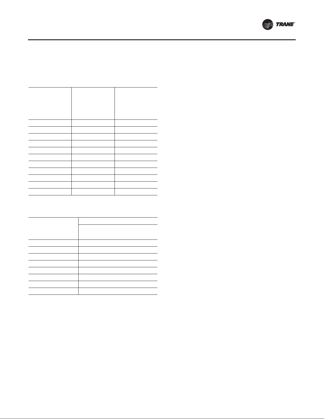
Table 1. Resistance input vs. setpoint temperature
RTM cooling or
heating setpoint
input used as the
source for a ZONE
temp setpoint (°F)
40 40 1084
45 45 992
50 50 899
55 55 796
60 60 695
65 65 597
70 70 500
75 75 403
80 80 305
n/a 85 208
n/a 90 111
RTM cooling
setpoint input
used as the source
for SUPPLY AIR
temp setpoint
cooling (°F)
Resistance (Ohms)
Max.
Tolerance 5%
Table 2. RTM resistance value vs. system operating
mode
Resistance applied to
RTM MODE input
Terminals (Ohms)
Max. Tolerance 5%
2320 Auto Off
4870 Auto Cool
7680 Auto Auto
10770 On Off
13320 On Cool
16130 On Auto
19480 Auto Heat
27930 On Heat
Constant Volume Units
Fan Mode System Mode
Rooftop Module (RTM - Standard on all units)
The rooftop Module (RTM) responds to cooling, heating,
and ventilation requests by energizing the proper unit
components based on information received from other
unit modules, sensors,
remote panels, and customer supplied binary inputs. It
initiates supply fan, exhaust fan, exhaust damper
positioning or variable frequency drive output, and
economizer operation based on
that information.
Compressor Module (MCM - standard on all
units)
The Compressor module, upon receiving a request for
mechanical cooling, energizes the appropriate
compressors and condenser fans. It monitors the
compressor operation through feedback information it
receives from various protection devices.
Human Interface Module (HI - standard on all
units)
The Human Interface module enables the operator to
adjust the operating parameters for the unit using a 16 key
keypad.The 2 line, 40 character LCD screen provides
status information for the various unit functions as well as
menus for the operator to set or modify the operating
parameters.
Heat Module (used on heating units)
The Heat module, upon receiving a request for Heating,
energizes the appropriate heating stages or strokes the
Modulating Heating valve as required.
Ventilation Override Module (VOM - Optional)
The Ventilation Override module initiates specified
functions such as; space pressurization, exhaust, purge,
purge with duct pressure control, and unit off when any
one of the five (5) binary inputs to the module are
activated.The compressors and condenser fans are
disabled during the ventilation operation. If more than one
ventilation sequence is activated, the one with the highest
priority is initiated.
Interprocessor Communications Board (IPCB Optional used with the Optional Remote
Human Interface)
The Interprocessor Communication Board expands
communications from the rooftop unit UCM network to a
Remote Human Interface Panel. DIP switch settings on the
IPCB module for this application should be; Switches 1 and
2“Off”, Switch 3 “On”.
Lontalk®/BACnet® Communication Interface
Module (LCI/BCI - Optional - used on units
with Trane ICS™ or 3rd party Building
Automation Systems)
The LonTalk/BACnet Communication Interface modules
expand communications from the unit UCM network to a
TraneTracer Summit™ or a 3rd party building automation
system and allow external setpoint and configuration
adjustment and monitoring of status and diagnostics.
Exhaust/Comparative Enthalpy Module
(ECEM - Optional used on units with Statitrac
and/or comparative enthalpy options)
The Exhaust/Comparative Enthalpy module receives
information from the return air humidity sensor, the
RT-SVX24K-EN 11
Page 12
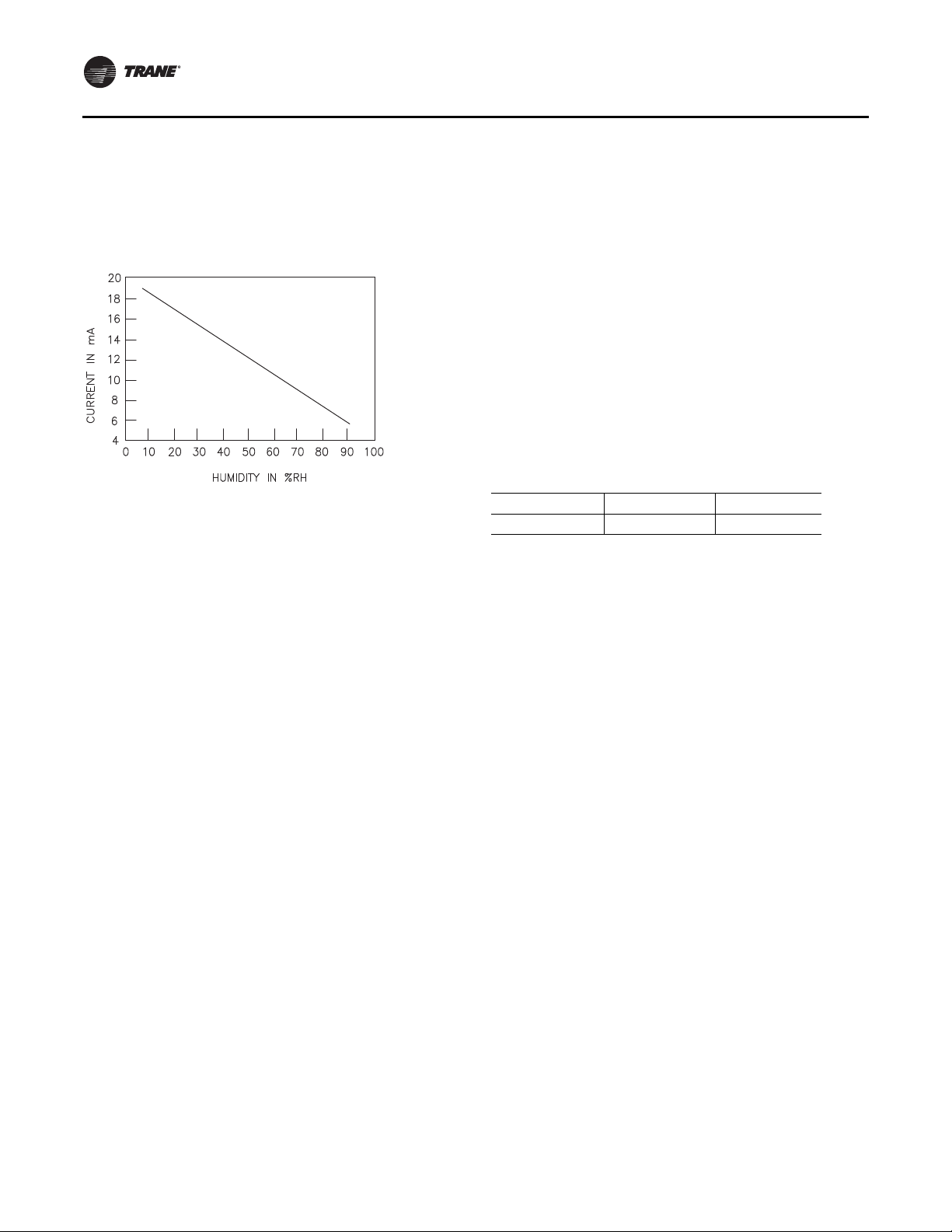
General Information
outside air humidity sensor,and the return air temperature
sensor to utilize the lowest possible humidity level when
considering economizer operation. In addition, it receives
space pressure information which is used to maintain the
space pressure to within the setpoint control band. Refer
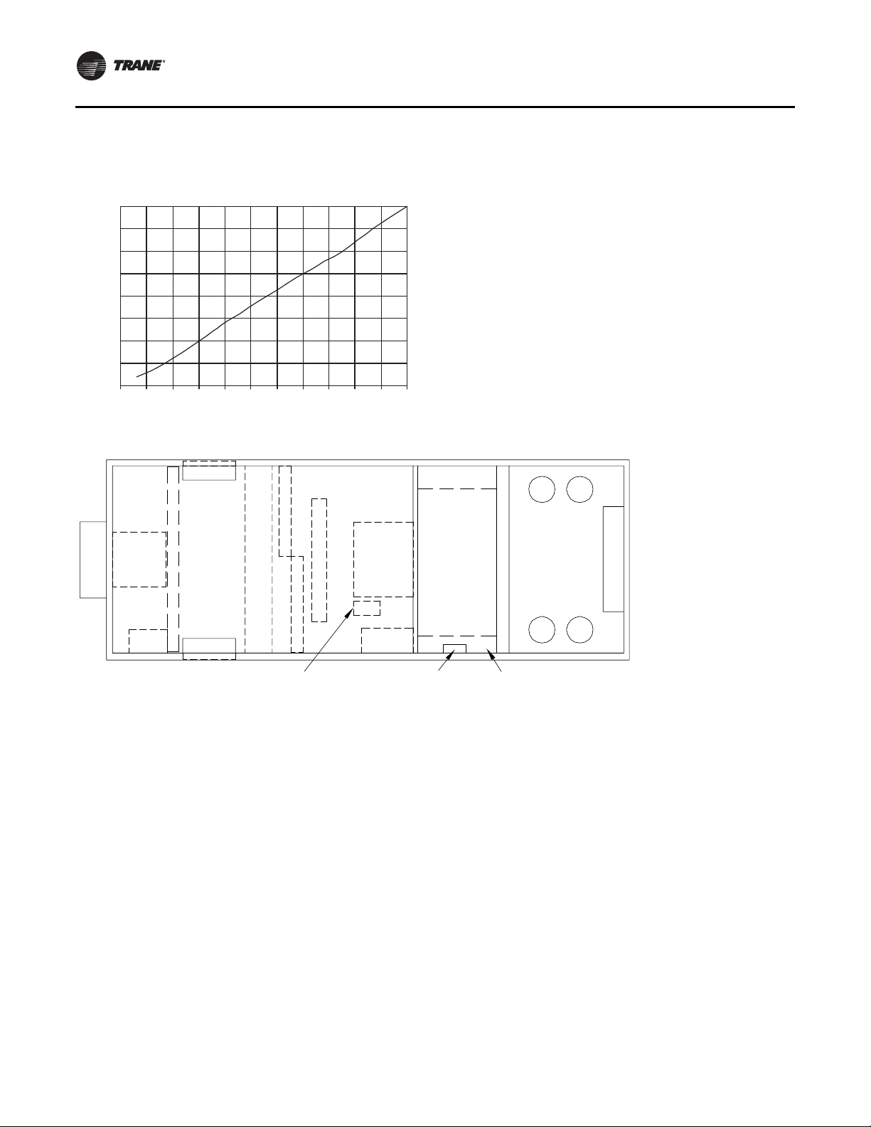
to Figure 1 for the Humidity vs. Voltage input values.
Figure 1. Humidity vs. current
Multi Purpose Module MPM (Optional - used
with Return Fan Control, Energy Recovery, and
Evaporative Condensers)
The MPM supports three optional features.The first of
which is return plenum pressure control by receiving
analog voltage information for measuring return plenum
pressure, calibrating that reading, and providing an output
to control the return fan speed (if variable speed
configured) in response to control algorithm requests.
This module also provides inputs and outputs for control
of all Energy Recovery feature devices including the
energy wheel, exhaust and outdoor air bypass dampers,
and recovery preheat.The liquid line pressure sensor
inputs for both refrigeration circuits are received through
the MPM in support of head pressure control on watercooled condenser units.
Ventilation Control Module (VCM)
The Ventilation Control Module (VCM) is located in the
filter section of the unit and is linked to the unit UCM
network. Using a “velocity pressure” sensing ring located
in the outside air section allows the VCM to monitor and
control the quantity of outside air entering the unit to a
minimum airflow setpoint.
An optional temperature sensor can be connected to the
VCM whichenables it to control a field installed outside air
preheater.An optional CO
VCM to control CO
minimum CFM upward as the CO
increase.
The maximum effective (reset) setpoint value for outside
air entering the unit is limited to the systems operating
CFM.The following table lists the velocity pressure vs.
Input Voltage (see also Figure 6, p. 18.).
Table 3. Minimum outside air setpoint w/VCM and
TRAQ™ sensing
Unit Input Volts CFM
90-162 Tons 0.5 - 4.5 VDC 0 - 46000
The velocity pressure transducer/solenoid assembly is
illustrated below. Refer to the “Units withTRAQ™ Sensor,”
p. 103 for VCM operation.
2
sensor can be connected to the
2
reset.The reset function adjusts the
concentrations
2
Variable Speed Module (VSM - Optional -
Used with Fault Detection and Diagnostics
FDD)
The VSM is used with FDD.The VSM will accept a 0-10Vdc
actuator feedback position signal which will then be used
to determine the state of OutsideAir Damper system.
Modulating Dehumidification Module MDM
(Optional - used with Dehumidification
Control)
The MDM supports specific control inputs and outputs for
Modulating Dehumidification control including
modulating Reheat and Cooling valve control as well as
the Reheat Pumpout Coil Relay output. The Modulating
Dehumidification control algorithm provides control
requests to the MDM to accomplish proper
Dehumidification control.
12 RT-SVX24K-EN
Page 13

Figure 2. Velocity pressure transducer/solenoid assembly
Figure 3. Outside air tubing schematic
General Information
Figure 4. Return air pressure tubing schematic
Generic Building Automation System Module
(GBAS - Optional used with
non-Trane building control systems)
The Generic Building Automation System (GBAS) module
allows a non-Trane building control system to
communicate with the rooftop unit and accepts external
setpoints in the form of analog inputs for cooling, heating,
supply air pressure, and a binary Input for demand limit.
Refer to the “Field Installed Control Wiring” section for the
input wiring to the GBAS module and the various desired
setpoints with the corresponding DC voltage inputs for
both VAV, SZVAV, RR and CV applications.
Input Devices and System Functions
The descriptions of the following basic Input Devices used
within the UCM network are to acquaint the operator with
their function as they interface with the various modules.
Refer to the unit electrical schematic for the specific
module connections.
Constant Volume (CV) and
Variable Air Volume (VAV) Units
Supply Air Temperature Sensor
An analog input device used with CV and VAV applications
that monitors the supply air temperature for: supply air
temperature control (VAV), supply air temperature reset
(VAV), supply air temperature low limiting (CV), supply air
tempering (CV/VAV). It is mounted in the supply air
discharge section of the unit and is connected to the RTM.
RT-SVX24K-EN 13
Page 14

General Information
Return Air Temperature Sensor
An analog input device used with a return humidity sensor
on CV and VAV applications when the comparative
enthalpy option is ordered. It monitors the return air
temperature and compares it to the outdoor temperature
to establish which temperature is best suited to maintain
the cooling requirements. It is mounted in the return air
section and is connected to the ECEM.
Leaving EvaporatorTemperature Sensor
An analog input device used with CV and VAV applications
that monitors the refrigerant temperature inside the
evaporator coil to prevent coil freezing. It is attached to the
suction line near the evaporator coil and is connected to
the MCM. It is factory set for 30°F and has an adjustable
range of 25°F to 35°F.The compressors are staged “Off” as
necessary to prevent icing. After the last compressor stage
has been turned “Off”, the compressors will be allowed to
restart once the evaporator temperature rises 10°F above
the“coil frost cutout temperature” and the minimum three
minute “Off” time has elapsed.
Entering Evaporator Temperature Sensors
Analog input devices used with CV and VAV applications.
This device is used in conjunction with the Leaving
EvaporatorTemperature Sensor to prevent the unit from
running compressors with insufficient charge.
Filter Switch
A binary input device used on CV and VAV applications
that measures the pressure differential across the unit
filters. It is mounted in the filter section and is connected
to the RTM. A diagnostic SERVICE signal is sent to the
remote panel if the pressure differential across the filters
is at least 0.5" w.c.The contacts will automatically open
when the pressure differential across the filters decrease
to 0.4" w.c.The switch differential can be field adjusted
between 0.17" w.c. to 5.0" w.c. ± 0.05" w.c.
Leaving Recovery Exhaust Temp Sensor
Analog input device used on CV andVAV applications with
Energy Recovery option installed. It is used to monitor the
temperature of the leaving air on the Exhaust Fan side of
the energy recovery wheel.This temperature is used to
determine if the temperature of the wheel is too cold as
compared to the Recovery Frost Avoidance Setpoint.The
result is used to determine when to enable energy wheel
frost avoidance functions.
Supply, Exhaust and Return Fan Airflow
Proving Switches
Supply Airflow Proving Switch is a binary input device
used on CV and VAV applications to signal the RTM when
the supply fan is operating. It is located in the supply fan
section of the unit and is connected to the RTM. During a
request for fan operation, if the differential switch is
detected to be open for 40 consecutive seconds;
compressor operation is turned “Off”, heat operation is
turned “Off”, the request for supply fan operation is turned
“Off” and locked out, exhaust dampers (if equipped) are
“closed”, economizer dampers (if equipped) are “closed”,
and a manual reset diagnostic is initiated.
Exhaust/return Airflow Proving Switch is a binary input
device used on all rooftop units equipped with an exhaust
fan. It is located in the exhaust/return fan section of the unit
and is connected to the RTM. During a request for fan
operation, if the differential switch is detected to be open
for 40 consecutive seconds, the economizer is closed to
the minimum position setpoint, the request for exhaust
fan operation is turned “Off” and locked out, and a manual
reset diagnostic is initiated.The fan failure lockout can be
reset at the Human Interface located in the unit control
panel, byTracer, or by cycling the control power to the
RTM Off/On.
Lead-Lag
A selectable mode of operation through the Human
Interface. It alternates the starting between the first
compressor of each refrigeration circuit. Only the
compressor banks will switch, not the order of the
compressors within a bank, providing the fir st compressor
in each circuit had been activated during the same request
for cooling.
Charge Isolation
During the OFF cycle, most of the charge is isolated
between the compressor (internal) discharge check valves
and liquid line solenoid valve.This reduces the OFF cycle
charge migration, and liquid feedback during subsequent
startup.The liquid line solenoid is energized (opened) with
the start of the circuit compressor.
Supply, Exhaust and Return Fan Circuit
Breakers
The supply fan and exhaust fan motors are protected by
circuit breakers or fuses. They will trip and interrupt the
power supply to the motors if the current exceeds the
breaker's “must trip” value.The rooftop module (RTM)
will shut all system functions “Off” when an open fan
proving switch is detected.
Low Pressure Control
Low Pressure Control is accomplished using a binary input
device on CV andVAV applications. LP cutouts are located
on the suction lines near the scroll compressors.The LPC
contacts are designed to close when the suction pressure
exceeds 41 ± 4 psig. If the LP control is open when a
compressor is requested to start, none of the compressors
on that circuit will be allowed to operate.They are locked
out and a manual reset diagnostic is initiated.
The LP cutouts are designed to open if the suction
pressure approaches 22 ± 4 psig. If the LP cutout opens
after a compressor has started, all compressors operating
on that circuit will be turned off immediately and will
14 RT-SVX24K-EN
Page 15

General Information
remain off for a minimum of three minutes. If the LP cutout
trips four consecutive times during the first three minutes
of operation, the compressors on that circuit will be locked
out and a manual reset diagnostic is initiated.
Saturated Condenser Temperature Sensors
Analog input devices used on CV and VAV applications
mounted inside a temperature well located on a
condenser tube bend.They monitor the saturated
refrigerant temperature inside the condenser coil and are
connected to the MCM. As the saturated refrigerant
temperature varies due to operating conditions, the
condenser fans are cycled “On” or “Off” as required to
maintain acceptable operating pressures.
Head Pressure Control
Accomplished using two saturated refrigerant
temperature sensors on CV and VAV applications. During
a request for compressor operation, when the condensing
temperature rises above the “lower limit” of the
controlband, the Compressor Module (MCM) starts
sequencing condenser fans “On”. If the operating fans can
not bring the condensing temperature to within the
controlband, more fans are turned on. As the saturated
condensing temperature approaches the lower limit of the
controlband, fans are sequenced “Off”.
The minimum “On/Off” time for condenser fan staging is
5.2 seconds. If the system is operating at a given fan stage
below 100% for 30 minutes and the saturated condensing
temperature is above the “efficiency check point” setting,
a fan stage will be added. If the saturated condensing
temperature falls below the “efficiency check point”
setting, the fan control will remain at the present operating
stage. If a fan stage cycles four times within a 10 minute
period, the control switches from controlling to the “lower
limit” to a temperature equal to the “lower limit” minus
the “temporary low limit suppression” setting. It will
utilize this new “low limit” temperature for one hour to
reduce condenser fan short cycling.
For evaporative condensing units, head pressure is
monitored with pressure transducers attached to the
saturated condensing line and converted to a temperature
by the MPM.This temperature is used to control the
variable speed fan and sump pump. When the
temperature rises above the upper limit (120°F) the sump
pump is energized. If the condensing temperature drops
below the lower limit (70°F) the sump pump is deenergized.
High Pressure Limit Controls
High Pressure controls are located on the discharge lines
near the scroll compressors. They are designed to open
when the discharge pressure approaches 650 ± 10 psig.
The controls reset automatically when the discharge
pressure decreases to approximately 550 ± 10 psig.
However, the compressors on that circuit are locked out
and a manual reset diagnostic is initiated after the fourth
occurrence of a high pressure condition.
Outdoor Air Humidity Sensor
An analog input device used on CV and VAV applications
with 100% economizer. It monitors the outdoor humidity
levels for economizer operation. It is mounted in the
outside air intake section and is connected to the RTM.
Return Air Humidity Sensor
An analog input device used on CV and VAV applications
with the comparative enthalpy option. It monitors the
return air humidity level and compares it to the outdoor
humidity level to establish which conditions are best
suited to maintain the cooling requirements. It is mounted
in the return air section and is connected to the ECEM.
Space Humidity Sensor
Analog input device used on CV andVAV applications with
modulating dehumidification option and/or
humidification field installed option. It is used to monitor
the humidity level in the space and compared to
dehumidification and humidification setpoints to maintain
space humidity requirements. It is field mounted in the
space and connected to the RTM.
Status/Annunciator Output
An internal function within the RTM module on CV and
VAV applications that provides:
c. diagnostic and mode status signals to the remote
panel (LEDs) and to the Human Interface
d. control of the binary Alarm output on the RTM
e. control of the binary outputs on the GBAS module
to inform the customer of the operational status
and/or diagnostic conditions
Low Ambient Compressor Lockout
Utilizes an analog input device for CV and VAV
applications. When the system is configured for low
ambient compressor lockout, the compressors are not
allowed to operate if the temperature of the outside air
falls below the lockout setpoint. When the temperature
rises 5°F above the lockout setpoint, the compressors are
allowed to operate.The factory preset is 50°F.
These compressors come equipped with a protection
module that monitors phase loss, phase sequencing and
motor temperature.
Space PressureTransducer
An analog input device used on CV and VAV applications
with the Statitrac option. It modulates the exhaust
dampers to keep the space pressure within the building to
a customer designated controlband. It is mounted on the
bottom support below the return damper blade assembly
and is connected to the ECEM. Field supplied pneumatic
tubing must be connected between the space being
controlled and the transducer assembly.
RT-SVX24K-EN 15
Page 16
General Information
MorningWarm-Up—Zone Heat
When a system changes from an unoccupied to an
occupied mode, or switches from STOPPED to AUTO, or
power is applied to a unit with the MWU option, the heater
in the unit or external heat will be brought on if the space
temperature is below the MWU setpoint.The heat will
remain on until the temperature reaches the MWU
setpoint.
If the unit is VAV, then the VAV box/unocc relay will
continue to stay in the unoccupied position and the VFD
output will stay at 100% during the MWU mode.When the
MWU setpoint is reached and the heat mode is terminated,
then the VAV box/unocc relay will switch to the occupied
mode and the VFD output will be controlled by the duct
static pressure. During Full Capacity MWU the economizer
damper is held closed for as long as it takes to reach
setpoint. During Cycling Capacity MWU the economizer
damper is allowed to go to minimum position after one
Compressor Motor Winding Thermostats
A thermostat is embedded in the motor windings of each
Scroll compressor. Each thermostat is designed to open if
the motor windings exceed approximately 221°F. The
thermostat will reset automatically when the winding
temperature decreases to approximately 181°F.
Rapid cycling, loss of charge, abnormally high suction
temperatures, or the compressor running backwards
could cause the thermostat to open. During a request for
compressor operation, if the Compressor Module detects
a problem outside of normal parameters, it turns any
operating compressor(s) on that circuit “Off”, locks out all
compressor operation for that circuit, and initiates a
manual reset diagnostic (compressor trip).
These compressors come equipped with a protection
module that monitors phase loss, phase sequencing and
motor temperature.
hour of operation if setpoint has not been reached.
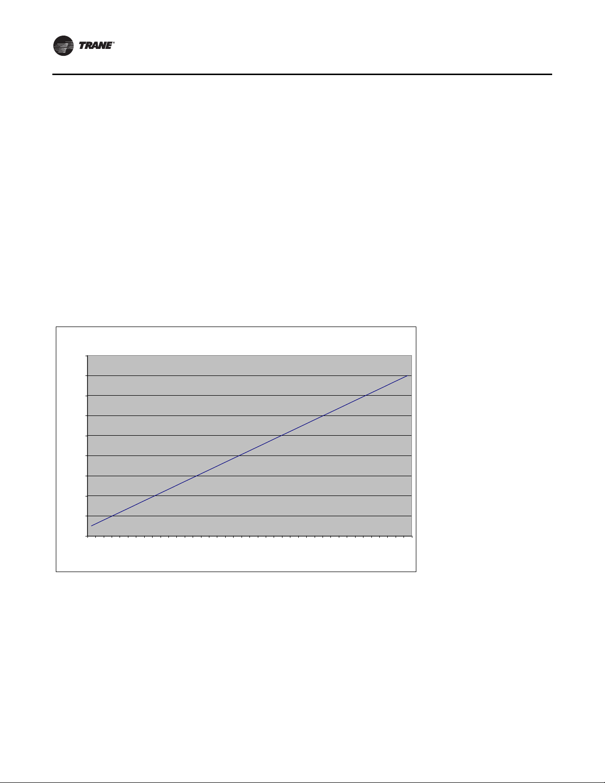
Figure 5. Transducer voltage output vs. pressure input for supply, return and building pressure
-0.75 to 9.0 Iwc Pressure Transducer Voltage Output vs. Pressure Input
4.50
4.00
3.50
3.00
2.50
Volts
2.00
1.50
1.00
0.50
0.00
5
5
5
5
5
5
5
5
5
250.2
75
-0.
-0.
7
2
7
2
7
2
0.
1.
1.
2.
2.
7
3.
3.
Pressure (inches w.c.)
5
2
7
4.
4.
5.
Supply Air Temperature Low Limit
Uses the supply air temperature sensor input to modulate
the economizer damper to minimum position in the event
the supply air temperature falls below the occupied
heating setpoint temperature.
Discharge Line Thermostat for Evaporative
Condensers
The first compressor on each circuit is equipped with a
Discharge Line Thermostat. If the temperature of the line
exceeds 210°F the thermostat interrupts the 115V circuit for
the compressors and both of the compressors on that
5
5
5
5
5
5
5
2
7
2
7
2
5.
6.
6.
7
7.
7.
5
2
7
8.
8.
circuit will be de-energized. Once the temperature drops
below 170°F the thermostat will close and allow the
compressor to be energized.
Freezestat
A binary input device used on CV and VAV units with
Hydronic Heat. It is mounted in the heat section and
connected to the Heat Module. If the temperature of the air
leaving the heating coil falls to 40°F, the normally open
contacts on the freezestat closes signalling the Heat
Module and the Rooftop Module (RTM) to:
f. drive the Hydronic Heat Actuator to the full open
position
16 RT-SVX24K-EN
Page 17

General Information
g. turn the supply fan “Off”
h. closes the outside air damper
i. turns “On” the SERVICE light at the Remote Panel
j. initiates a “Low Temp Limit” diagnostic to the
Human Interface
Compressor Circuit Breakers
The Scroll Compressors are protected by circuit breakers
whichinterrupt the power supply to the compressors if the
current exceeds the breakers “must trip” value. During a
request for compressor operation, if the Compressor
Module detects a problem outside normal parameters, it
turns any operating compressor(s) on that circuit “Off”,
locks out all compressor operation for that circuit, and
initiates a manual reset diagnostic (compressor trip).
Constant Volume (CV) Units
Zone Temperature—Cooling
Relies on input from a sensor located directly in the space,
while a system is in the occupied “Cooling” mode. It
modulates the economizer (if equipped) and/or stages the
mechanical cooling “On and Off” as required to maintain
the zone temperature to within the cooling setpoint
deadband.
Zone Temperature—Heating
Relies on input from a sensor located directly in the space,
while a system is in the occupied “Heating” mode or an
unoccupied period, to stage the heat “on and off” or to
modulate the heating valve (hydronic heat only) as
required to maintain the zone temperature to within the
heating setpoint deadband.The supply fan will be
requested to operate any time there is a request for heat.
On gas heat units, the fan will continue to run for 60
seconds after the furnace is turned off.
Supply Air Tempering
On CV units equipped with staged gas heat, if the supply
air temperature falls 10°F below the occupied heating
setpoint temperature while the heater is “Off”, the first
stage of heat will be turned “On”.The heater is turned “Off”
when the supply air temperature reaches 10°F above the
occupied heating setpoint temperature.
Variable Air Volume (VAV) Units
Occupied Cooling—Supply Air Temperature
When a VAV unit is in the occupied mode, the supply air
temperature will be controlled to the customer specified
supply air cooling setpoint by modulating the economizer
and/or staging the mechanical cooling “On and Off” as
required.The changeover relay contacts must be open, or
BAS command set to auto or cool, for the cooling to
operate.
DaytimeWarm-up
On VAV units equipped with heat, if the zone temperature
falls below the daytime warm-up initiate temperature
during the occupied mode, the system will switch to full
airflow. During this mode, theVAV box/unocc relay will be
energized (this is to signal the VAV boxes to go to 100%).
After theVAV box max stroke time has elapsed (factory set
at 6 minutes), the VFD output will be set to 100%.The
airflow will be at 100% and the heat will be turned on to
control to the occupied heating setpoint.
When the zone temperature reaches the daytime warm-up
termination setpoint, the heat will be turned off, the relay
will be de-energized, releasing the VAV boxes, the VFD
output will go back to duct static pressure control and the
unit will return to discharge air control. If the occ zone
heating setpoint is less than the DWU terminate setpoint,
the heat will turn off when the occ zone heat setpoint is
reached, but it will stay in DWU mode and cycle the heat
to maintain setpoint.
Unoccupied Heating—Zone Temperature
When aVAV unit is equipped with gas, electric, or hydronic
heat and is in the unoccupied mode, the zone temperature
will be controlled to within the customer specified setpoint
deadband. During an unoccupied mode for aVAV unit, the
VAV box/unocc relay will be in the unoccupied position
and theVFD output will be at 100%.This means that if there
is a call for heat (or cool) and the supply fan comes on, it
will be at full airflow and the VAV boxes in the space will
need to be 100% open as signaled by the VAV box/unocc
relay.
Supply Air Tempering
On VAV units equipped with “Modulating Heat”,ifthe
supply air temperature falls 10°F below the supply air
temperature setpoint, the heat will modulate to maintain
the supply air temperature to within the low end of the
setpoint deadband.
Occupied Heating—Supply Air Temperature
When a VAV unit is equipped with “Modulating Heat”, and
the system is in an occupied mode, and the field supplied
changeover relay contacts have closed or per a BAS
command, the supply air temperature will be controlled to
the customer specified supply air heating setpoint. It will
remain in the heating status until the changeover relay
contacts are opened or BAS has released the heat
command.
RT-SVX24K-EN 17
Supply Duct Static Pressure Control
(Occupied)
The RTM relies on input from the duct pressure transducer
when a unit is equipped with aVariable Frequency Drive to
set the supply fan speed to maintain the supply duct static
pressure to within the static pressure setpoint deadband.
The transducer compares supply duct pressure to ambient
pressure. Refer to Figure 43, p. 67.
Page 18
General Information
Figure 6. Transducer voltage output vs. pressure input
with VCM and TRAQ™ sensing
4.0
3.5
3.0
2.5
2.0
Volts
1.5
1.0
0.5
0.0
Transducer Voltage Output vs. Pressure I nput
-0.5 0.0 0.5 1.0 1.5 2.0 2.5 3.0 3.5 4.0 4.5 5.0
Pre ssu re (inche s w.c.)
Figure 7. Unit component layout and “ship with” locations
Outside Air
Dampers
Evap Coil
Return/
Exhaust
Hood
Exhaust Damper
Fan
Return Air Dampers
Filter Section
Reheat Coil Option
Evap Coil
Supply Fan
Space Temperature Averaging
Space temperature averaging for Constant Volume
applications is accomplished by wiring a number of
remote sensors in a series/parallel circuit.
The fewest number of sensors required to accomplish
space temperature averaging is four.The Space
Temperature Averaging with Multiple Sensors figure
illustrates a single sensor circuit (Single Zone), four
sensors wired in a series/parallel circuit (Four Zone), nine
sensors wired in a series/parallel circuit (Nine Zone). Any
number squared, is the number of remote sensors
required.
Wiring termination will depend on the type of remote
panel or control configuration for the system. Refer to the
wiring diagrams that shipped with the unit.
Condenser
Heating
Section
Fans
Compressor
Section
Controls
Variable
Frquency
Drive (VFD)
Outside Air
Dampers
Outside Air
Static Kit and
sensors
Variable
Frquency
Drive (VFD)
Flue Vent
Access
Hot Water/Steam
Hydronic Connection
18 RT-SVX24K-EN
Page 19
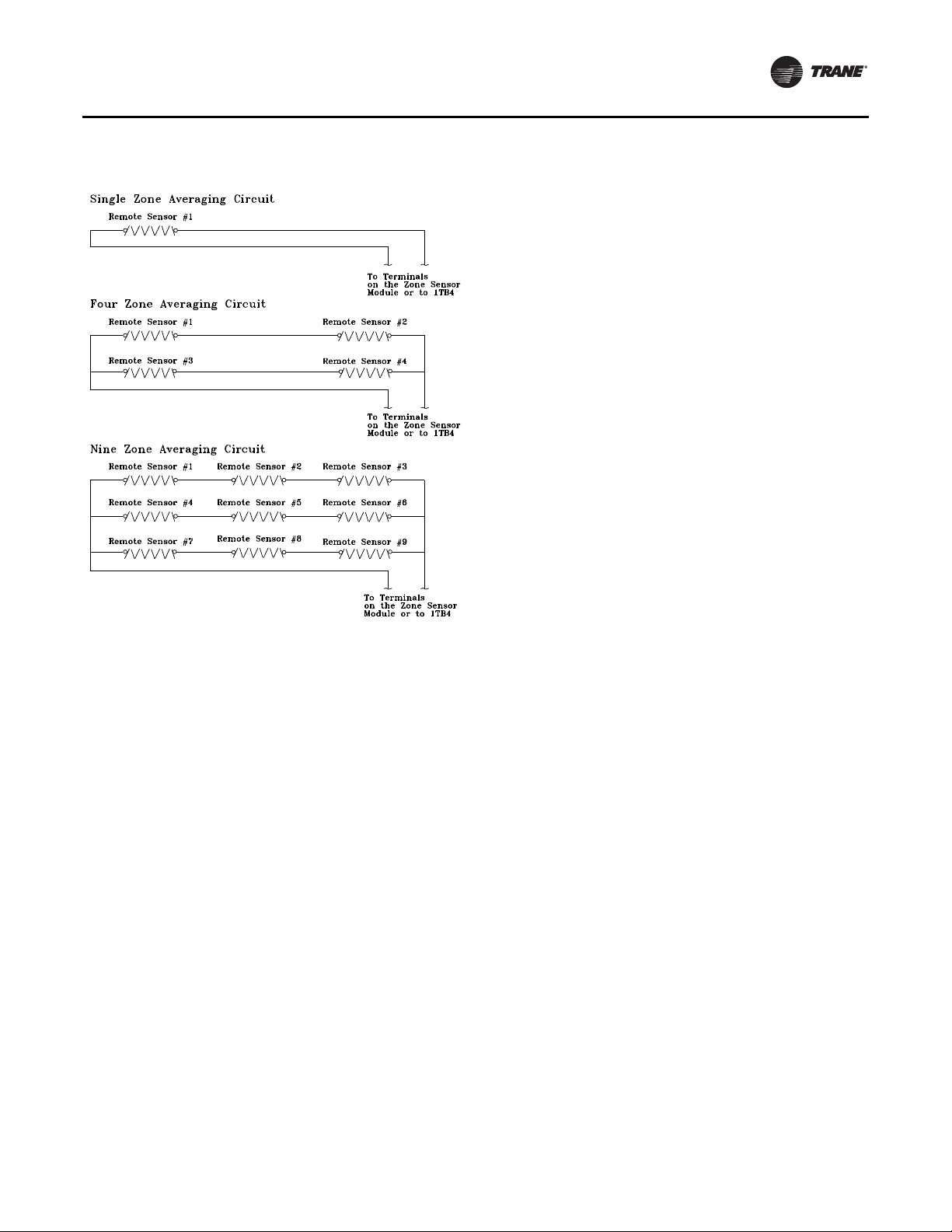
Figure 8. Space temperature averaging with multiple
sensors
General Information
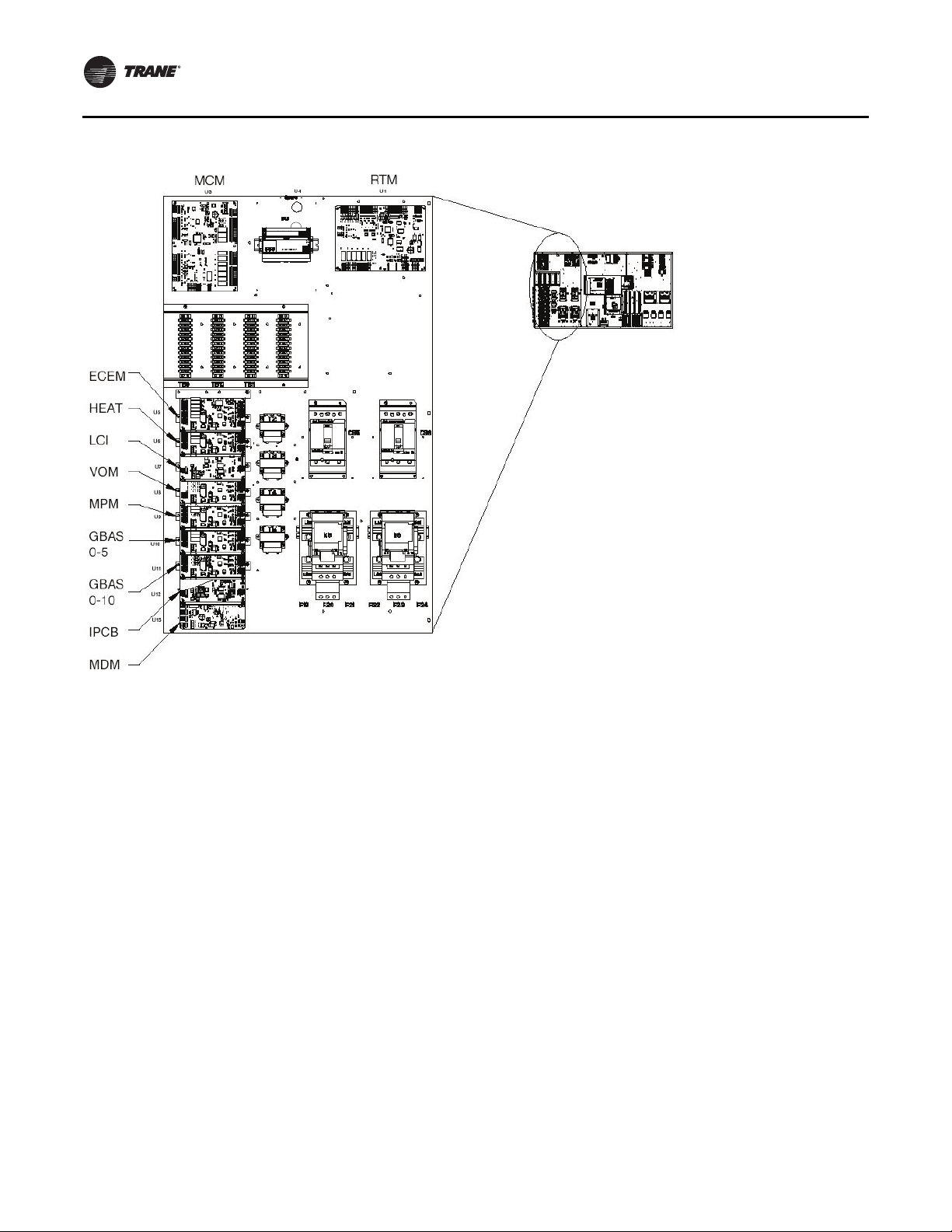
Unit Control Modules
Unit control modules are microelectronic circuit boards
designed to perform specific unit functions.The control
modules, through proportional/integral control
algorithms, provide the best possible comfort level for the
customer.They are mounted in the control panel and are
factory wired to their respective internal components.
The control modules receive and interpret information
from other unit modules, sensors, remote panels, and
customer binary contacts to satisfy the applicable request
for economizing, mechanical cooling, heating, and
ventilation. Figure 9 illustrates the typical location of each
designated module.
RT-SVX24K-EN 19
Page 20
General Information
Figure 9. Control module locations
BCI
Single Zone Variable Air Volume (SZVAV) Only
The IntelliPak controls platform will support Single Zone
VAV as an optional unit control type in order to meet
ASHRAE 90.1. The basic control will be a hybrid VAV/CV
configured unit that provides discharge temperature
control to a varying discharge air temperature target
setpoint based on the space temperature and/or humidity
conditions. Concurrently, the unit will control and optimize
the supply fan speed to maintain the zone temperature to
a zone temperature setpoint.
Supply Fan Output Control
Units configured for Single Zone VAV control will utilize
the same supply fan output control scheme as on
traditional VAV units except the VFD signal will be based
on zone heating and cooling demand instead of the supply
air pressure.
VFD Control
Single Zone VAV units will be equipped with a VFDcontrolled supply fan which will be controlled via a 010VDC signal from the Rooftop Module (RTM). With the
RTM supply fan output energized and the RTM VFD output
at 0VDC, the fan speed output is 37% (22Hz) from the VFD
by default; and at 10VDC the fan speed output is 100%
(60Hz).The control scales the 0-10VDC VFD output from
the RTM linearly to control between the 37-100% range.
The VFD will modulate the supply fan motor speed,
accelerating or decelerating as required to maintain the
zone temperature to the zone temperature setpoint.When
subjected to high ambient return conditions the VFD will
reduce its output frequency to maintain operation. Bypass
control is offered to provide full nominal airflow in the
event of drive failure.
Ventilation Control
Units configured for Single Zone VAV control will require
special handling of the OA Damper Minimum Position
control in order to compensate for the non-linearity of
airflow associated with the variable supply fan speed and
damper combinations. Units configured for TRAQ with or
without DCV will operate identically to traditional units
with no control changes.
Space Pressure Control
For units configured with Space Pressure Control with or
without Statitrac, the new schemes implemented for
economizer minimum position handling require changes
to the existing Space Pressure Control scheme in order to
20 RT-SVX24K-EN
Page 21

General Information
prevent over/under pressurization.The overall scheme
will remain very similar to VAV units with Space Pressure
Control with the exception of the dynamic Exhaust Enable
Setpoint.
For SZVAV an Exhaust Enable Setpoint must be selected
during the 100% Fan Speed Command. Once selected, the
difference between the Exhaust Enable Setpoint and
Design OA Damper Minimum Position at 100% Fan Speed
Command will be calculated.The difference calculated will
be used as an offset and added to the Active Building
Design OA Minimum PositionTarget in order to calculate
the dynamic Exhaust EnableTarget, which will be used
throughout the Supply Fan Speed/OA Damper Position
range.
The Exhaust EnableTarget could be above or below the
Active Building Design OA Minimum PositionTarget
Setpoint, based on the Active Exhaust Enable Setpoint
being set above or below the Building Design Minimum
Position at 100% Fan Speed Command. Note that an
Exhaust Enable Setpoint of 0% will result in the same effect
on Exhaust Fan control as on VAV applications with and
without Statitrac.
Occupied Cooling Operation
For normal cooling operation, cooling capacity will be
staged or modulated in order to meet the calculated
discharge air target setpoint. If the current active cooling
capacity is controlling the discharge air within the
deadband, no additional cooling capacity change will be
requested. As the Discharge Air Temperature rises above
the deadband, the algorithm will request additional
capacity as required (additional compressors or
economizer).As the Discharge AirTemperature falls below
the deadband, the algorithm will request a reduction in
active capacity.
Default Economizer Operation
By default, the unit will be setup to optimize the minimum
supply fan speed capability during Economizer Only
operation. If the economizer is able to meet the demand
alone, due to desirable ambient conditions, the supply fan
speed will be allowed to increase above the minimum
prior to utilizing mechanical cooling if discharge air
setpoint falls below the discharge air Lower Limit
(Cooling) setpoint.
Unoccupied Mode
In Unoccupied mode the unit will utilize setback setpoints,
0% Minimum OA Damper position, and Auto Fan Mode
operation as on normal CV units.The Supply Fan speed,
and cooling and modulating types of heat, will be
controlled to the discharge air target setpoint as is done
during occupied periods.The Supply fan speed during
staged heat control will be forced to 100% as on normal CV
units.
Occupied Heating Operation
Occupied heating operation has two separate control
sequences; staged and modulated. All staged heating
types will drive the supply fan to maximum flow and stage
heating to control to the Zone Heating Setpoint. For units
with Hydronic and Gas heat, modulated SZVAV Heating.
On an initial call for heating, the supply fan will drive to the
minimum heating airflow.
On an additional call for heating, the heat will control in
order to meet the calculated discharge air target setpoint.
As the load in the zone continues to request heat
operation, the supply fan will ramp-up while the control
maintains the heating discharge air temperature. Heating
can be configured for either the energy saving SZVAV
Heating solution as described above, or the traditional,
less efficient CV Heating solution.
Compressor (DX) Cooling
Compressor control and protection schemes will function
identical to that of a traditional unit. Normal compressor
proving and disable input monitoring will remain in effect
as well as normal 3-minute minimum on, off, and interstage timers. Also, all existing head pressure control
schemes will be in effect.
Cooling Sequence
If the control determines that there is a need for active
cooling capacity in order to meet the calculated discharge
air target setpoint, once supply fan proving has been
made, the unit will begin to stage compressors
accordingly. Note that the compressor staging order will
be based on unit configuration and compressor lead/lag
status.
Once the discharge air target setpoint calculation has
reached the Minimum Setpoint and compressors are
being utilized to meet the demand, as the discharge air
target setpoint value continues to calculate lower the
algorithm will begin to ramp the supply fan speed up
toward 100%. Note that the supply fan speed will remain
at the compressor stage’s associated minimum value (as
described below) until the discharge air target setpoint
value is calculated below the discharge air temperature
Minimum Setpoint (limited discharge air target setpoint).
As the cooling load in the zone decreases the zone cooling
algorithm will reduce the speed of the fan down to
minimum per compressor stage and control the
compressors accordingly. As the compressors begin to
de-energize, the supply fan speed will fall back to the
Cooling Stage’s associated minimum fan speed, but not
below. As the load in the zone continues to drop, cooling
capacity will be reduced in order to maintain the discharge
air within the ± ½ discharge air target deadband.
Fault Detection and Diagnostics
Fault Detection of the Outdoor Air Damper will be
evaluated based on the commanded position of the
damper compared to the feedback position of the damper.
RT-SVX24K-EN 21
Page 22

General Information
The damper is commanded to a position based on a 2-10
VDC signal. If the Damper position is outside of ±10% of the
commanded position, a diagnostic is generated.
Unit Not Economizing when it should be:
The Unit is operating in Cooling Mode, Economizing is
enabled and/or Mechanical Cooling is enabled. If the
Commanded Economizer Position is greater than Current
Economizer Feedback Position + 10% for 5 continuous
minutes, Unit Not Economizing when it should be
diagnostic is generated.
Unit Economizing when it should not be:
The unit is operating in Cooling Mode, Economizing is
enabled and or Mechanical Cooling is enabled. If the
commanded Economizer Position is less than the current
Economizer Feedback Position - 10% for 5 continuous
minutes, Unit Economizing When it should not be
diagnostic is generated.
Outdoor Air Damper Not Modulating
The unit is operating in Ventilation Only Mode - not
attempting to Economize and the Commanded Damper
Position is greater than the Current Damper Feedback
Position + 10% for 5 continuous minutes, Outdoor Air
Damper Not Modulating diagnostic is generated.
Excessive Outdoor Air
The unit is operating in Ventilation Only Mode - not
attempting to Economize and the Commanded Damper
Position is less than the Current Damper Feedback Position
- 10% for 5 continuous minutes. Excessive Outdoor Air
diagnostic is generated.
To changethe Economizer Control Function to dry bulb, go
to the Configuration Menu on the Human Interface Module
and set Comparative Enthalpy to "Not Installed".This
allows the user to select dry bulb under the Economizer
Control Function which is a Submenu of the Setup Menu.
For additional instructions please see the Programming
andTroubleshooting Guide.
22 RT-SVX24K-EN
Page 23
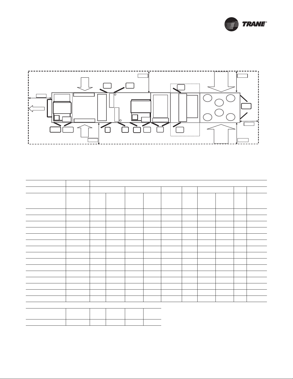
Unit Clearances
(F)
(R)
(
(
)
e
Filters
(a)
AH R
Fltr
Fltr
Std StdStd
Evp
OptionOption
VFD
Evp
Sup
Sup
VFD
Mtr
Std
Figure 10. Minimum required clearance
Outside
Exh
Exhaust
VFD
As Req.
Outsid
Air
AH L
Rtn/Exh
Mtr
Rtn/Exh
VFD
Left Side
(a)Unit drawing is representative only and may not accurately depict all models.
Table 4. Minimum required clearance
Unit Option Selection (Door Swing Ft. and In.)
Standard VFD Two-side Access
Heat
Heat
L&R
As Req. As Req.
Blank Section
Fnl
Fltr
As Req.
Final
Filter
Fnl
Fltr
As Req.
Condenser
Condenser
Cond R
Cond L
Ctrl Box
L&R
CBox
Std
Door Location Availability 90-118 120-162
Return/
Exhaust Supply Heat Reheat 90-118 120-162
Final
Filter
Energy
Recovery
Exhaust/Ret Motor Std 2' 2" 2' 2" * * * * * * *
Exhaust/Ret VFD As Req. * * 2' 2" * * * * * *
(a)
ERW Fltr
(L & R) (F) Option * * * * * * * * * 2' 2"
ERW Fltr(a) (L & R) (R) Option * * * * * * * * * 2' 2"
Filter (Front) Std 2' 8" 2' 8" * * * * * * *
Filter (Rear) Option * * * * * * 2' 2" 2' 8" *
Evap (Front) Std 2' 2" 2' 2" * * * * * * *
Evap (Rear) Std 2' 8" * * * * * * * *
or Evap (Rear) Option * * * * * 2' 2 * 2' 2" *
Supply Motor Std 2' 8" 2' 8" * * * * * * *
Supply VFD As Req. * * * 2' 2" * * * * *
Heat (Left & Right) As Req. * * * * 2' 2" * * * *
Final Filter (Front) As Req. * * * * * * * * 2' 2"
Final Filter (Rear) As Req. * * * * * * * * 2' 2"
Control Box (L & R) Std 3' 2" 3' 2" * * * * * * *
Minimum Required Clearance (Ft.)
Control
AH_L AH_R Exh Cond_L Cond_R
Box
8' 8' 8' 8' 8' 6'
(a)See Unit Dimensions for Energy Recovery Wheel location.
RT-SVX24K-EN 23
Page 24
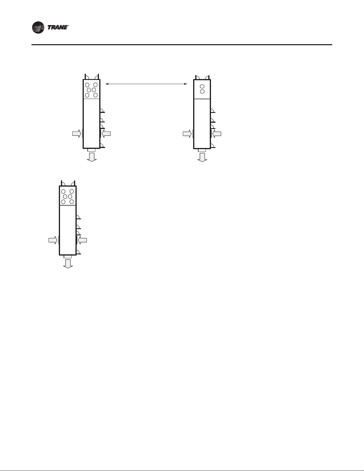
Unit Clearances
Figure 11. Multiple unit placement
Minimum distance between units must be 16’!
Outdoor
Air Intake
Exhaust
Air
Outdoor
Air Intake
Exhaust
Air
Notes:
1. Stagger units to minimize span deflection which deters sound
transmission and to maximize proper diffusion of the exhaust air
before it reaches the adjacent unit outside air intake.
2. Cooling tower should be 5 feet above or 20 feet away from the outside
air intake. For additional information, see 2007 ASHRAE Handbook:
HVAC Applications, page 44.4.
Outdoor
Air Intake
Outdoor
Air Intake
Outdoor
Air Intake
Exhaust
Air
Outdoor
Air Intake
24 RT-SVX24K-EN
Page 25
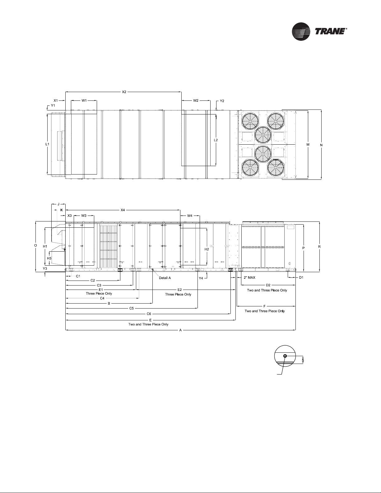
Dimensional Data
Figure 12. Unit Top/Front View
Detail A
1-1/4 NPT. DRAIN
2X TYP. LEFT & RIGHT SIDES OF UNIT
RT-SVX24K-EN 25
Page 26
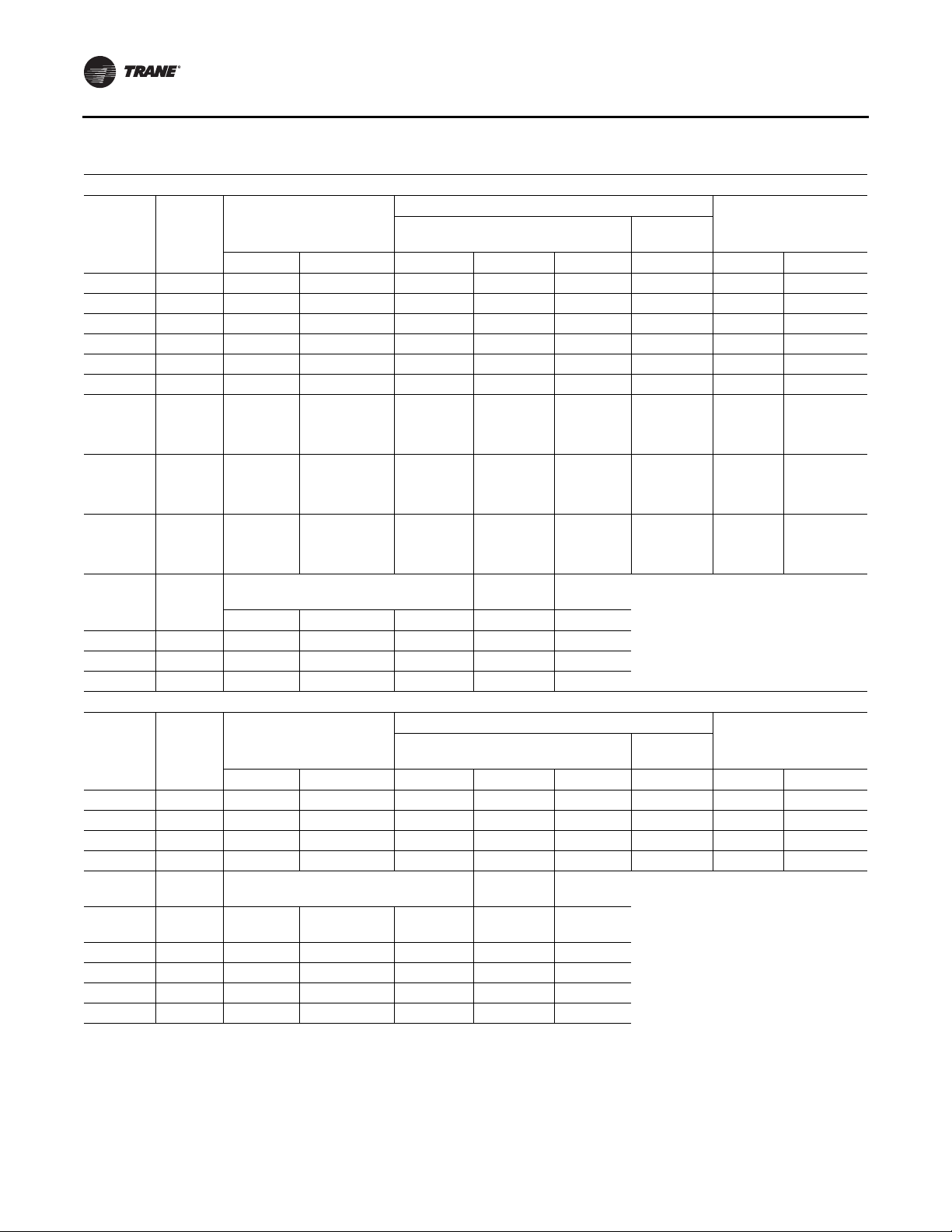
Dimensional Data
Table 5. Unit dimensions (in.)—one-piece unit air-cooled
ONE-PIECE Dimensions without Energy Recovery Wheel (ERW)
Lifting Lug Locations
Tonnage
90 None 437 3/16 159 15/16 66 252 14/16 N/A 27 11/16 139 13/16 143 8/16
90 4 ft 485 6/16 159 15/16 66 252 14/16 N/A 54 2/16 139 13/16 143 8/16
90 8 ft 533 9/16 159 15/16 66 252 14/16 N/A 54 2/16 139 13/16 143 8/16
105 None 455 3/16 159 15/16 66 252 14/16 N/A 27 11/16 139 13/16 143 8/16
105 4 ft 503 6/16 159 15/16 66 252 14/16 N/A 54 2/16 139 13/16 143 8/16
105 8 ft 551 9/16 159 15/16 66 252 14/16 N/A 54 2/16 139 13/16 143 8/16
120-150 (All
Units Except
High Heat
Gas Models)
120-150 (All
Units Except
High Heat
Gas Models)
120-150
(High Heat
Gas Models
Only)
Section
None 528 15/16 197 1/16 66 269 6/16 N/A 63 2/16 139 13/16 143 8/16
4 ft 577 2/16 197 1/16 66 269 6/16 N/A 63 2/16 139 13/16 143 8/16
None 540 15/16 197 1/16 66 269 6/16 N/A 63 2/16 139 13/16 143 8/16
Blank
Unit Dimensions
A B C1 C2 C3 D1 M N
Exhaust
Tonnage
90-150 None 103 12/16 97 9/16 103 7/16 29 3/16 17
90-150 4 ft 103 12/16 97 9/16 103 7/16 29 3/16 17
90-150 8 ft 103 12/16 97 9/16 103 7/16 29 3/16 17
Section
OPRJK
Blank
Unit Height Return Fan
Fan
ONE-PIECE Dimensions with Energy Recovery Wheel
Lifting Lug Locations
Tonnage
90 None 533 9/16 256 5/16 66 201 1/16 349 4/16 27 11/16 139 13/16 143 8/16
90 4 ft 581 13/16 256 5/16 66 201 1/16 349 4/16 54 2/16 139 13/16 143 8/16
105 None 551 9/16 256 5/16 66 201 1/16 349 4/16 27 11/16 139 13/16 143 8/16
105 4 ft 599 13/16 256 5/16 66 201 1/16 349 4/16 54 2/16 139 13/16 143 8/16
Section
Blank
Unit Dimensions
A B C1 C2 C3 D1 M N
Exhaust
Unit Height Return Fan
Fan
Blank
Tonnage
90 None 103 12/16 97 9/16 103 7/16 N/A 17
90 4 ft 103 12/16 97 9/16 103 7/16 N/A 17
105 None 103 12/16 97 9/16 103 7/16 N/A 17
105 4 ft 103 12/16 97 9/16 103 7/16 N/A 17
Section O P R J K
Condenser
Side
Condenser
Side
Unit WidthAir Handler Side
Unit WidthAir Handler Side
26 RT-SVX24K-EN
Page 27
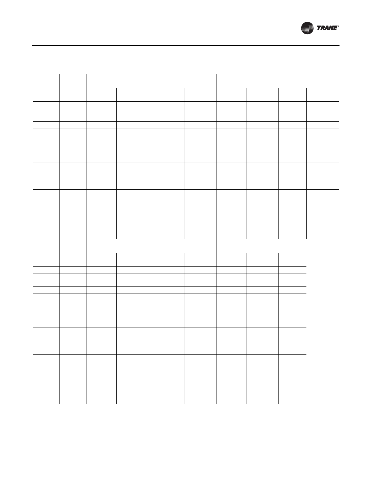
Dimensional Data
Table 6. Unit dimensions (In.)—two-piece unit air-cooled
TWO-PIECE Dimensions without Energy Recovery Wheel (ERW)
Lifting Lug Locations
Tonnage
90 None 454 4/16 159 15/16 330 14/16 121 6/16 66 252 14/16 N/A N/A
90 4 ft 502 7/16 159 15/16 379 1/16 121 6/16 66 252 14/16 368 6/16 N/A
90 8 ft 550 11/16 159 15/16 427 4/16 121 6/16 66 252 14/16 416 10/16 N/A
105 None 472 4/16 159 15/16 330 14/16 139 6/16 66 252 14/16 N/A N/A
105 4 ft 520 7/16 159 15/16 379 1/16 139 6/16 66 252 14/16 368 6/16 N/A
105 8 ft 568 11/16 159 15/16 427 4/16 139 6/16 66 252 14/16 416 10/16 N/A
120-150
(All Units
Except High
Heat Gas
Models)
120-150
(All Units
Except High
Heat Gas
Models)
120-150
(All Units
Except High
Heat Gas
Models)
120-150
(High Heat
Gas Models
Only)
Section
None 546 197 1/16 395 10/16 148 6/16 66 269 6/16 384 15/16 N/A
4 ft 594 4/16 197 1/16 443 13/16 148 6/16 66 269 6/16 433 2/16 N/A
8 ft 642 7/16 197 1/16 492 1/16 148 6/16 66 269 6/16 481 6/16 N/A
None 558 197 1/16 407 10/16 148 6/16 66 269 6/16 396 15/16 N/A
A B E F C1 C2 C3 C4
Blank
Unit Dimensions
Lug Locations
Blank
Tonnage
90 None 16 112 7/16 139 13/16 143 8/16 103 12/16 97 9/16 103 7/16
90 4 ft 16 112 7/16 139 13/16 143 8/16 103 12/16 97 9/16 103 7/16
90 8 ft 16 112 7/16 139 13/16 143 8/16 103 12/16 97 9/16 103 7/16
105 None 16 130 7/16 139 13/16 143 8/16 103 12/16 97 9/16 103 7/16
105 4 ft 16 130 7/16 139 13/16 143 8/16 103 12/16 97 9/16 103 7/16
105 8 ft 16 130 7/16 139 13/16 143 8/16 103 12/16 97 9/16 103 7/16
120-150
(All Units
Except High
Heat Gas
Models)
120-150
(All Units
Except High
Heat Gas
Models)
120-150
(All Units
Except High
Heat Gas
Models)
120-150
(High Heat
Gas Models
Only)
Continued on next page
Section
None 16 139 7/16 139 13/16 143 8/16 103 12/16 97 9/16 103 7/16
4 ft 16 139 7/16 139 13/16 143 8/16 103 12/16 97 9/16 103 7/16
8 ft 16 139 7/16 139 13/16 143 8/16 103 12/16 97 9/16 103 7/16
None 16 139 7/16 139 13/16 143 8/16 103 12/16 97 9/16 103 7/16
D1 D2 M N O P R
Unit Width Unit HeightCondenser Side
Air Handler Side
RT-SVX24K-EN 27
Page 28
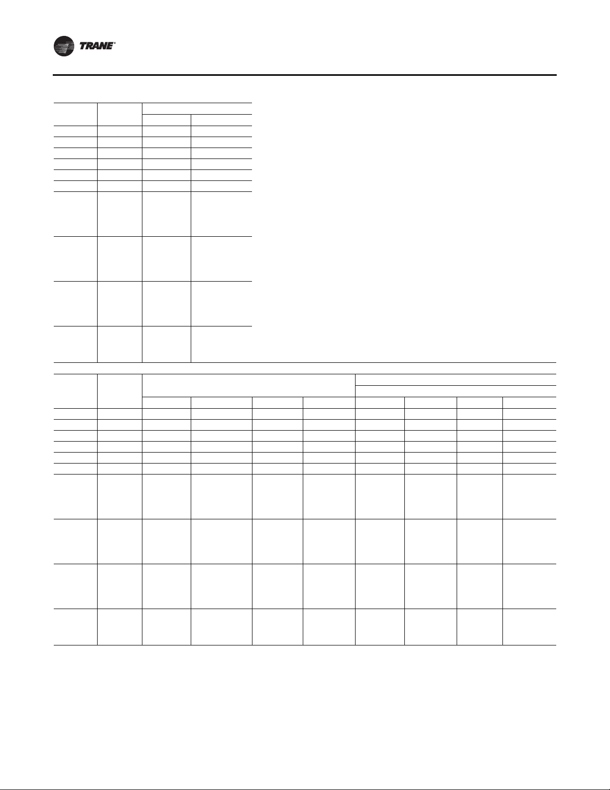
Dimensional Data
Table 6. Unit dimensions (In.)—two-piece unit air-cooled (continued)
Tonnage
90 None 29 3/16 17
90 4 ft 29 3/16 17
90 8 ft 29 3/16 17
105 None 29 3/16 17
105 4 ft 29 3/16 17
105 8 ft 29 3/16 17
120-150
(All Units
Except High
Heat Gas
Models)
120-150
(All Units
Except High
Heat Gas
Models)
120-150
(All Units
Except High
Heat Gas
Models)
120-150
(High Heat
Gas Models
Only)
Section
None 29 3/16 17
None 29 3/16 17
Blank
Blank
Tonnage
90 None 550 11/16 256 5/16 427 5/16 121 6/16 66 201 1/16 349 4/16 N/A
90 4 ft 598 14/16 256 5/16 475 8/16 121 6/16 66 201 1/16 349 4/16 464 13/16
90 8 ft 647 2/16 256 5/16 523 12/16 121 6/16 66 201 1/16 349 4/16 513
105 None 568 11/16 256 5/16 427 5/16 139 6/16 66 201 1/16 349 4/16 N/A
105 4 ft 616 14/16 256 5/16 475 8/16 139 6/16 66 201 1/16 349 4/16 464 13/16
105 8 ft 665 2/16 256 5/16 523 12/16 139 6/16 66 201 1/16 349 4/16 513
120-150
(All Units
Except High
Heat Gas
Models)
120-150
(All Units
Except High
Heat Gas
Models)
120-150
(All Units
Except High
Heat Gas
Models)
120-150
(High Heat
Gas Models
Only)
Continued on next page
Section
None 642 7/16 293 8/16 492 1/16 148 6/16 66 238 5/16 365 5/16 480 14/16
4 ft 690 10/16 293 8/16 540 4/16 148 6/16 66 238 5/16 365 5/16 529 2/16
8 ft 738 14/16 293 8/16 588 8/16 148 6/16 66 238 5/16 365 5/16 577 5/16
None 654 7/16 293 8/16 504 1/16 148 6/16 66 238 5/16 365 5/16 492 14/16
Return Fan Exhaust Fan
JK
4 ft 29 3/16 17
8 ft 29 3/16 17
TWO-PIECE Dimensions with Energy Recovery Wheel (ERW)
Unit Dimensions
A B E F C1 C2 C3 C4
Lifting Lug Locations
Air Handler Side
28 RT-SVX24K-EN
Page 29
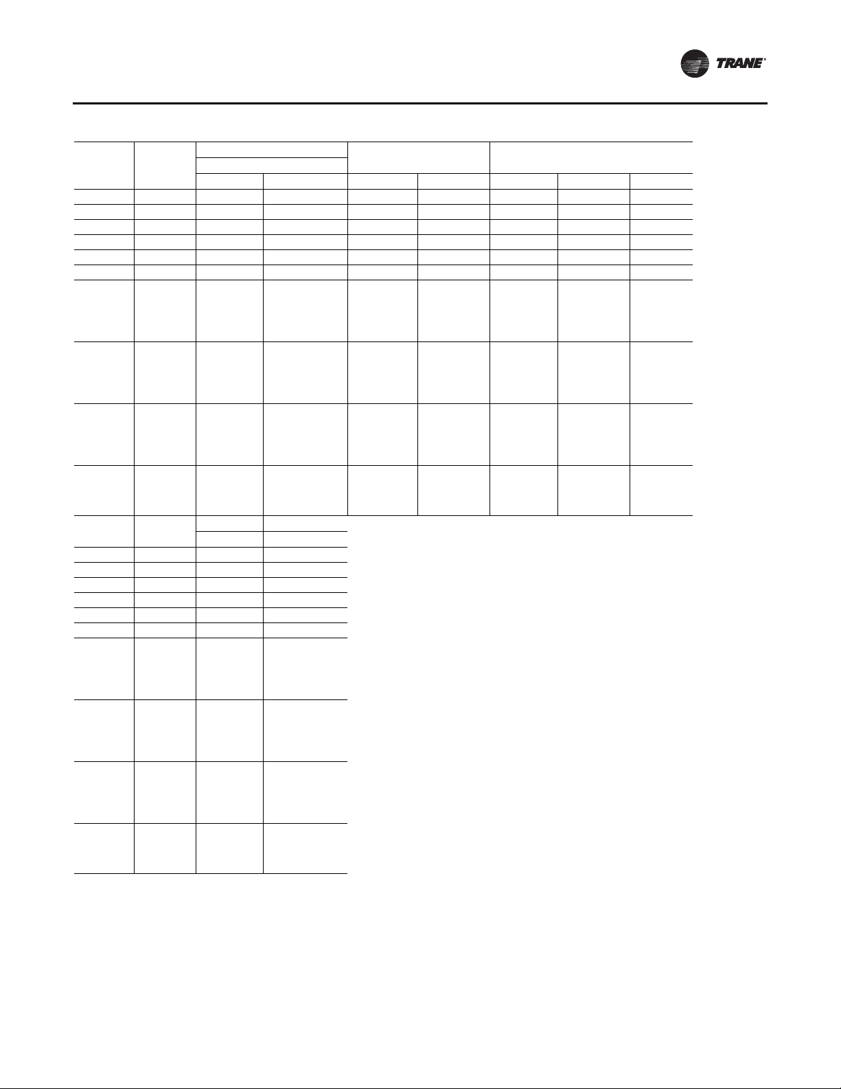
Table 6. Unit dimensions (In.)—two-piece unit air-cooled (continued)
Lug Locations
Blank
Tonnage
90 None 16 112 7/16 139 13/16 143 8/16 103 12/16 97 9/16 103 7/16
90 4 ft 16 112 7/16 139 13/16 143 8/16 103 12/16 97 9/16 103 7/16
90 8 ft 16 112 7/16 139 13/16 143 8/16 103 12/16 97 9/16 103 7/16
105 None 16 130 7/16 139 13/16 143 8/16 103 12/16 97 9/16 103 7/16
105 4 ft 16 130 7/16 139 13/16 143 8/16 103 12/16 97 9/16 103 7/16
105 8 ft 16 130 7/16 139 13/16 143 8/16 103 12/16 97 9/16 103 7/16
120-150
(All Units
Except High
Heat Gas
Models)
120-150
(All Units
Except High
Heat Gas
Models)
120-150
(All Units
Except High
Heat Gas
Models)
120-150
(High Heat
Gas Models
Only)
Section
None 16 139 7/16 139 13/16 143 8/16 103 12/16 97 9/16 103 7/16
4 ft 16 139 7/16 139 13/16 143 8/16 103 12/16 97 9/16 103 7/16
8 ft 16 139 7/16 139 13/16 143 8/16 103 12/16 97 9/16 103 7/16
None 16 139 7/16 139 13/16 143 8/16 103 12/16 97 9/16 103 7/16
Blank
Tonnage
90 None N/A 17
90 4 ft N/A 17
90 8 ft N/A 17
105 None N/A 17
105 4 ft N/A 17
105 8 ft N/A 17
120-150
(All Units
Except High
Heat Gas
Models)
120-150
(All Units
Except High
Heat Gas
Models)
120-150
(All Units
Except High
Heat Gas
Models)
120-150
(High Heat
Gas Models
Only)
Section
None N/A 17
4 ft N/A 17
8 ft N/A 17
None N/A 17
D1 D2 M N O P R
Return Fan Exhaust Fan
JK
Unit WidthCondenser Side Unit Height
Dimensional Data
RT-SVX24K-EN 29
Page 30
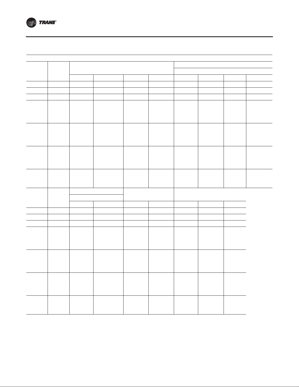
Dimensional Data
Table 7. Unit dimensions (in.)—two-piece unit evaporative condenser
TWO-PIECE Dimensions without Energy Recovery Wheel (ERW)
Lifting Lug Locations
Tonnage
100-118 None 475 8/16 159 15/16 330 14/16 142 10/16 66 252 14/16 N/A N/A
100-118 4 ft 523 12/16 159 15/16 379 1/16 142 10/16 66 252 14/16 368 6/16 N/A
100-118 8 ft 571 15/16 159 15/16 427 5/16 142 10/16 66 252 14/16 416 10/16 N/A
128-162
(All Units
Except High
Heat Gas
Models)
128-162
(All Units
Except High
Heat Gas
Models)
128-162
(All Units
Except High
Heat Gas
Models)
128-162
(High Heat
Gas Models
Only)
Section
None 540 5/16 197 1/16 395 10/16 142 10/16 66 269 6/16 384 15/16 N/A
4 ft 588 8/16 197 1/16 443 14/16 142 10/16 66 269 6/16 433 2/16 N/A
8 ft 636 11/16 197 1/16 492 1/16 142 10/16 66 269 6/16 481 6/16 N/A
None 552 5/16 197 1/16 407 10/16 142 10/16 66 269 6/16 396 15/16 N/A
A B E F C1 C2 C3 C4
Blank
Unit Dimensions
Lug Locations
Tonnage
100-118 None 16 133 11/16 139 13/16 143 8/16 103 12/16 97 9/16 102 12/16
100-118 4 ft 16 133 11/16 139 13/16 143 8/16 103 12/16 97 9/16 102 12/16
100-118 8 ft 16 133 11/16 139 13/16 143 8/16 103 12/16 97 9/16 102 12/16
128-162
(All Units
Except High
Heat Gas
Models)
128-162
(All Units
Except High
Heat Gas
Models)
128-162
(All Units
Except High
Heat Gas
Models)
128-162
(High Heat
Gas Models
Only)
Continued on next page
Section
None 16 133 11/16 139 13/16 143 8/16 103 12/16 97 9/16 102 12/16
4 ft 16 133 11/16 139 13/16 143 8/16 103 12/16 97 9/16 102 12/16
8 ft 16 133 11/16 139 13/16 143 8/16 103 12/16 97 9/16 102 12/16
None 16 133 11/16 139 13/16 143 8/16 103 12/16 97 9/16 102 12/16
Blank
Condenser Side Unit Width Unit Height
D1 D2 M N O P R
Air Handler Side
30 RT-SVX24K-EN
Page 31

Table 7. Unit dimensions (in.)—two-piece unit evaporative condenser (continued)
Dimensional Data
Tonnage
100-118 None 29 3/16 17
100-118 4 ft 29 3/16 17
100-118 8 ft 29 3/16 17
128-162
(All Units
Except High
Heat Gas
Models)
128-162
(All Units
Except High
Heat Gas
Models)
128-162
(All Units
Except High
Heat Gas
Models)
128-162
(High Heat
Gas Models
Only)
Section
None 29 3/16 17
None 29 3/16 17
Blank
Return Fan Exhaust Fan
JK
4 ft 29 3/16 17
8 ft 29 3/16 17
TWO-PIECE Dimensions with Energy Recovery Wheel (ERW)
Lifting Lug Locations
Tonnage
100-118 None 571 15/16 256 5/16 427 5/16 142 10/16 66 201 1/16 349 4/16 N/A
100-118 4 ft 620 3/16 256 5/16 475 8/16 142 10/16 66 201 1/16 349 4/16 464 13/16
100-118 8 ft 668 6/16 256 5/16 523 12/16 142 10/16 66 201 1/16 349 4/16 513
128-162
(All Units
Except High
Heat Gas
Models)
128-162
(All Units
Except High
Heat Gas
Models)
128-162
(All Units
Except High
Heat Gas
Models)
128-162
(High Heat
Gas Models
Only)
Continued on next page
Section
None 636 11/16 293 8/16 492 1/16 142 10/16 66 238 5/16 365 5/16 480 14/16
4 ft 684 15/16 293 8/16 540 4/16 142 10/16 66 238 5/16 365 5/16 529 2/16
8 ft 733 2/16 293 8/16 588 8/16 142 10/16 66 238 5/16 365 5/16 577 5/16
None 648 11/16 293 8/16 504 1/16 142 10/16 66 238 5/16 365 5/16 492 14/16
A B E F C1 C2 C3 C4
Blank
Unit Dimensions
Air Handler Side
RT-SVX24K-EN 31
Page 32

Dimensional Data
Table 7. Unit dimensions (in.)—two-piece unit evaporative condenser (continued)
Lug Locations
Tonnage
100-118 None 16 133 11/16 139 13/16 143 8/16 103 12/16 97 9/16 102 12/16
100-118 4 ft 16 133 11/16 139 13/16 143 8/16 103 12/16 97 9/16 102 12/16
100-118 8 ft 16 133 11/16 139 13/16 143 8/16 103 12/16 97 9/16 102 12/16
128-162
(All Units
Except High
Heat Gas
Models)
128-162
(All Units
Except High
Heat Gas
Models)
128-162
(All Units
Except High
Heat Gas
Models)
128-162
(High Heat
Gas Models
Only)
Tonnage
100-118 None N/A 17
100-118 4 ft N/A 17
100-118 8 ft N/A 17
128-162
(All Units
Except High
Heat Gas
Models)
128-162
(All Units
Except High
Heat Gas
Models)
128-162
(All Units
Except High
Heat Gas
Models)
128-162
(High Heat
Gas Models
Only)
Section
None 16 133 11/16 139 13/16 143 8/16 103 12/16 97 9/16 102 12/16
4 ft 16 133 11/16 139 13/16 143 8/16 103 12/16 97 9/16 102 12/16
8 ft 16 133 11/16 139 13/16 143 8/16 103 12/16 97 9/16 102 12/16
None 16 133 11/16 139 13/16 143 8/16 103 12/16 97 9/16 102 12/16
Blank
Section
None N/A 17
4 ft N/A 17
8 ft N/A 17
None N/A 17
D1 D2 M N O P R
Return Fan Exhaust Fan
JK
Blank
Unit Width Unit HeightCondenser Side
32 RT-SVX24K-EN
Page 33

Dimensional Data
Table 8. Unit dimensions (in.)—three-piece unit air-cooled
THREE-PIECE Dimensions without Energy Recovery Wheel (ERW)
Lifting Lug Locations
Tonnage
90 None 473 9/16 179 3/16 350 3/16 144 15/16 205 3/16 121 6/16 11 14/16 N/A
90 4 ft 521 12/16 179 3/16 398 6/16 144 15/16 253 7/16 121 6/16 11 14/16 N/A
90 8 ft 569 15/16 179 3/16 446 9/16 144 15/16 301 10/16 121 6/16 11 14/16 N/A
105 None 491 9/16 179 3/16 350 3/16 144 15/16 205 3/16 139 6/16 11 14/16 N/A
105 4 ft 539 12/16 179 3/16 398 6/16 144 15/16 253 7/16 139 6/16 11 14/16 N/A
105 8 ft 587 15/16 179 3/16 446 9/16 144 15/16 301 10/16 139 6/16 11 14/16 N/A
120-150 (All
Units Except
High Heat
Gas Models)
120-150 (All
Units Except
High Heat
Gas Models)
120-150 (All
Units Except
High Heat
Gas Models)
120-150
(High Heat
Gas Models
Only)
Section
None 571 8/16 222 9/16 421 2/16 161 2/16 260 148 6/16 11 14/16 N/A
4 ft 619 11/16 222 9/16 469 5/16 161 2/16 308 4/16 148 6/16 11 14/16 N/A
8 ft 667 15/16 222 9/16 517 9/16 161 2/16 356 7/16 148 6/16 11 14/16 N/A
None 583 8/16 222 9/16 433 2/16 161 2/16 272 148 6/16 11 14/16 N/A
A B E E1 E2 F C1 C2
Blank
Unit Dimensions
Lug Locations
Blank
Tonnage
90 None 138 9/16 151 6/16 272 339 11/16 16 112 7/16 139 13/16 143 8/16
90 4 ft 138 9/16 151 6/16 272 387 14/16 16 112 7/16 139 13/16 143 8/16
90 8 ft 138 9/16 151 6/16 272 436 1/16 16 112 7/16 139 13/16 143 8/16
105 None 138 9/16 151 6/16 272 339 11/16 16 130 7/16 139 13/16 143 8/16
105 4 ft 138 9/16 151 6/16 272 387 14/16 16 130 7/16 139 13/16 143 8/16
105 8 ft 138 9/16 151 6/16 272 436 1/16 16 130 7/16 139 13/16 143 8/16
120-150 (All
Units Except
High Heat
Gas Models)
120-150 (All
Units Except
High Heat
Gas Models)
120-150 (All
Units Except
High Heat
Gas Models)
120-150
(High Heat
Gas Models
Only)
continued on next page
Section
None 155 2/16 167 5/16 294 14/16 410 10/16 16 139 7/16 139 13/16 143 8/16
4 ft 155 2/16 167 5/16 294 14/16 458 13/16 16 139 7/16 139 13/16 143 8/16
8 ft 155 2/16 167 5/16 294 14/16 507 1/16 16 139 7/16 139 13/16 143 8/16
None 155 2/16 167 5/16 294 14/16 422 10/16 16 139 7/16 139 13/16 143 8/16
C3 C4 C5 C6 D1 D2 M N
Air Handler Side
Unit WidthAir Handler Side Condenser Side
RT-SVX24K-EN 33
Page 34

Dimensional Data
Table 8. Unit dimensions (in.)—three-piece unit air-cooled (continued)
Tonnage
90 None 103 12/16 97 9/16 103 7/16 29 3/16 17
90 4 ft 103 12/16 97 9/16 103 7/16 29 3/16 17
90 8 ft 103 12/16 97 9/16 103 7/16 29 3/16 17
105 None 103 12/16 97 9/16 103 7/16 29 3/16 17
105 4 ft 103 12/16 97 9/16 103 7/16 29 3/16 17
105 8 ft 103 12/16 97 9/16 103 7/16 29 3/16 17
120-150 (All
Units Except
High Heat
Gas Models)
120-150 (All
Units Except
High Heat
Gas Models)
120-150 (All
Units Except
High Heat
Gas Models)
120-150
(High Heat
Gas Models
Only)
Section
None 103 12/16 97 9/16 103 7/16 29 3/16 17
4 ft 103 12/16 97 9/16 103 7/16 29 3/16 17
8 ft 103 12/16 97 9/16 103 7/16 29 3/16 17
None 103 12/16 97 9/16 103 7/16 29 3/16 17
Blank
Unit Height Return Fan Exhaust Fan
OPRJ K
THREE-PIECE Dimensions with Energy Recovery Wheel (ERW)
Lifting Lug Locations
Tonnage
90 None 569 15/16 275 10/16 446 9/16 241 6/16 205 3/16 121 6/16 17 12/16 201 1/16
90 4 ft 618 3/16 275 10/16 494 13/16 241 6/16 253 7/16 121 6/16 17 12/16 201 1/16
90 8 ft 666 6/16 275 10/16 543 241 6/16 301 10/16 121 6/16 17 12/16 201 1/16
105 None 587 15/16 275 10/16 446 9/16 241 6/16 205 3/16 139 6/16 17 12/16 201 1/16
105 4 ft 636 3/16 275 10/16 494 13/16 241 6/16 253 7/16 139 6/16 17 12/16 201 1/16
105 8 ft 684 6/16 275 10/16 543 241 6/16 301 10/16 139 6/16 17 12/16 201 1/16
120-150 (All
Units Except
High Heat
Gas Models)
120-150 (All
Units Except
High Heat
Gas Models)
120-150 (All
Units Except
High Heat
Gas Models)
120-150
(High Heat
Gas Models
Only)
continued on next page
Section
None 667 15/16 318 15/16 517 9/16 257 8/16 260 148 6/16 17 12/16 204 7/16
4 ft 716 2/16 318 15/16 565 12/16 257 8/16 308 4/16 148 6/16 17 12/16 204 7/16
8 ft 764 5/16 318 15/16 613 15/16 257 8/16 356 7/16 148 6/16 17 12/16 204 7/16
None 679 15/16 318 15/16 529 9/16 257 8/16 272 148 6/16 17 12/16 204 7/16
A B E E1 E2 F C1 C2
Blank
Unit Dimensions
Air Handler Side
34 RT-SVX24K-EN
Page 35

Dimensional Data
Table 8. Unit dimensions (in.)—three-piece unit air-cooled (continued)
Lug Locations
Tonnage
90 None 234 13/16 247 13/16 368 7/16 436 2/16 16 112 7/16 139 13/16 143 8/16
90 4 ft 234 13/16 247 13/16 368 7/16 484 5/16 16 112 7/16 139 13/16 143 8/16
90 8 ft 234 13/16 247 13/16 368 7/16 532 8/16 16 112 7/16 139 13/16 143 8/16
105 None 234 13/16 247 13/16 368 7/16 436 2/16 16 130 7/16 139 13/16 143 8/16
105 4 ft 234 13/16 247 13/16 368 7/16 484 5/16 16 130 7/16 139 13/16 143 8/16
105 8 ft 234 13/16 247 13/16 368 7/16 532 8/16 16 130 7/16 139 13/16 143 8/16
120-150 (All
Units Except
High Heat
Gas Models)
120-150 (All
Units Except
High Heat
Gas Models)
120-150 (All
Units Except
High Heat
Gas Models)
120-150
(High Heat
Gas Models
Only)
Tonnage
90 None 103 12/16 97 9/16 103 7/16 N/A 17
90 4 ft 103 12/16 97 9/16 103 7/16 N/A 17
90 8 ft 103 12/16 97 9/16 103 7/16 N/A 17
105 None 103 12/16 97 9/16 103 7/16 N/A 17
105 4 ft 103 12/16 97 9/16 103 7/16 N/A 17
105 8 ft 103 12/16 97 9/16 103 7/16 N/A 17
120-150 (All
Units Except
High Heat
Gas Models)
120-150 (All
Units Except
High Heat
Gas Models)
120-150 (All
Units Except
High Heat
Gas Models)
120-150
(High Heat
Gas Models
Only)
Section
None 252 12/16 263 12/16 391 5/16 507 1/16 16 139 7/16 139 13/16 143 8/16
4 ft 252 12/16 263 12/16 391 5/16 555 4/16 16 139 7/16 139 13/16 143 8/16
8 ft 252 12/16 263 12/16 391 5/16 603 7/16 16 139 7/16 139 13/16 143 8/16
None 252 12/16 263 12/16 391 5/16 519 1/16 16 139 7/16 139 13/16 143 8/16
Blank
Section
None 103 12/16 97 9/16 103 7/16 N/A 17
4 ft 103 12/16 97 9/16 103 7/16 N/A 17
8 ft 103 12/16 97 9/16 103 7/16 N/A 17
None 103 12/16 97 9/16 103 7/16 N/A 17
C3 C4 C5 C6 D1 D2 M N
Unit Height Return Fan Exhaust Fan
OPRJ K
Blank
Unit WidthAir Handler Side Condenser Side
RT-SVX24K-EN 35
Page 36

Dimensional Data
Table 9. Unit dimensions (in.)—three-piece unit evaporative condenser
THREE-PIECE Dimensions without Energy Recovery Wheel (ERW)
Lifting Lug Location
Tonnage
100/118 None 494 13/16 179 3/16 350 3/16 144 15/16 205 3/16 142 10/16 11 14/16 N/A
100/118 4 ft 543 179 3/16 398 6/16 144 15/16 253 7/16 142 10/16 11 14/16 N/A
100/118 8 ft 591 4/16 179 3/16 446 9/16 144 15/16 301 10/16 142 10/16 11 14/16 N/A
128-162 (All
Units Except
High Heat Gas
Models)
128-162 (All
Units Except
High Heat Gas
Models)
128-162 (All
Units Except
High Heat Gas
Models)
128-162 (High
Heat Gas
Models Only)
Section
None 565 12/16 222 9/16 421 2/16 161 2/16 260 142 10/16 11 14/16 N/A
4 ft 613 15/16 222 9/16 469 5/16 161 2/16 308 4/16 142 10/16 11 14/16 N/A
8 ft 662 3/16 222 9/16 517 9/16 161 2/16 356 7/16 142 10/16 11 14/16 N/A
None 577 12/16 222 9/16 433 2/16 161 2/16 272 142 10/16 11 14/16 N/A
A B E E1 E2 F C1 C2
Blank
Unit Dimensions
Lifting Lug Locations
Blank
Tonnage
100/118 None 138 9/16 151 6/16 272 339 11/16 16 133 11/16 139 13/16 143 8/16
100/118 4 ft 138 9/16 151 6/16 272 387 14/16 16 133 11/16 139 13/16 143 8/16
100/118 8 ft 138 9/16 151 6/16 272 436 1/16 16 133 11/16 139 13/16 143 8/16
128-162 (All
Units Except
High Heat Gas
Models)
128-162 (All
Units Except
High Heat Gas
Models)
128-162 (All
Units Except
High Heat Gas
Models)
128-162 (High
Heat Gas
Models Only)
continued on next page
Section
None 155 2/16 167 5/16 294 14/16 410 10/16 16 133 11/16 139 13/16 143 8/16
4 ft 155 2/16 167 5/16 294 14/16 458 13/16 16 133 11/16 139 13/16 143 8/16
8 ft 155 2/16 167 5/16 294 14/16 507 1/16 16 133 11/16 139 13/16 143 8/16
None 155 2/16 167 5/16 294 14/16 422 10/16 16 133 11/16 139 13/16 143 8/16
C3 C4 C5 C6 D1 D2 M N
Air Handler Side
Unit WidthAir Handler Side Condenser Side
36 RT-SVX24K-EN
Page 37

Table 9. Unit dimensions (in.)—three-piece unit evaporative condenser (continued)
Dimensional Data
Tonnage
100/118 None 103 12/16 97 9/16 102 12/16 29 3/16 17
100/118 4 ft 103 12/16 97 9/16 102 12/16 29 3/16 17
100/118 8 ft 103 12/16 97 9/16 102 12/16 29 3/16 17
128-162 (All
Units Except
High Heat Gas
Models)
128-162 (All
Units Except
High Heat Gas
Models)
128-162 (All
Units Except
High Heat Gas
Models)
128-162 (High
Heat Gas
Models Only)
Section
None 103 12/16 97 9/16 102 12/16 29 3/16 17
4 ft 103 12/16 97 9/16 102 12/16 29 3/16 17
8 ft 103 12/16 97 9/16 102 12/16 29 3/16 17
None 103 12/16 97 9/16 102 12/16 29 3/16 17
OPRJK
Blank
Unit Height Return Fan
Fan
THREE-PIECE Dimensions with Energy Recovery Wheel (ERW)
Lifting Lug Locations
Exhaust
Tonnage
100/118 None 591 4/16 275 10/16 446 9/16 241 6/16 205 3/16 142 10/16 17 12/16 201 1/16
100/118 4 ft 639 7/16 275 10/16 494 13/16 241 6/16 253 7/16 142 10/16 17 12/16 201 1/16
100/118 8 ft 687 10/16 275 10/16 543 241 6/16 301 10/16 142 10/16 17 12/16 201 1/16
128-162 (All
Units Except
High Heat Gas
Models)
128-162 (All
Units Except
High Heat Gas
Models)
128-162 (All
Units Except
High Heat Gas
Models)
128-162 (High
Heat Gas
Models Only)
continued on next page
Section
None 662 3/16 318 15/16 517 9/16 257 8/16 260 142 10/16 17 12/16 204 7/16
4 ft 710 6/16 318 15/16 565 12/16 257 8/16 308 4/16 142 10/16 17 12/16 204 7/16
8 ft 758 10/16 318 15/16 613 15/16 257 8/16 356 7/16 142 10/16 17 12/16 204 7/16
None 674 3/16 318 15/16 529 9/16 257 8/16 272 142 10/16 17 12/16 204 7/16
A B E E1 E2 F C1 C2
Blank
Unit Dimensions
Air Handler Side
RT-SVX24K-EN 37
Page 38

Dimensional Data
Table 9. Unit dimensions (in.)—three-piece unit evaporative condenser (continued)
Lifting Lug Locations
Tonnage
100/118 None 234 13/16 247 13/16 368 7/16 436 2/16 16 133 11/16 139 13/16 143 8/16
100/118 4 ft 234 13/16 247 13/16 368 7/16 484 5/16 16 133 11/16 139 13/16 143 8/16
100/118 8 ft 234 13/16 247 13/16 368 7/16 532 8/16 16 133 11/16 139 13/16 143 8/16
128-162 (All
Units Except
High Heat Gas
Models)
128-162 (All
Units Except
High Heat Gas
Models)
128-162 (All
Units Except
High Heat Gas
Models)
128-162 (All
Units Except
High Heat Gas
Models)
128-162 (High
Heat Gas
Models Only)
Section
None 252 12/16 263 12/16 391 5/16 519 1/16 16 133 11/16 139 13/16 143 8/16
4 ft 252 12/16 263 12/16 391 5/16 507 1/16 16 133 11/16 139 13/16 143 8/16
4 ft 252 12/16 263 12/16 391 5/16 507 1/16 16 133 11/16 139 13/16 143 8/16
8 ft 252 12/16 263 12/16 391 5/16 555 4/16 16 133 11/16 139 13/16 143 8/16
None 252 12/16 263 12/16 391 5/16 603 7/16 16 133 11/16 139 13/16 143 8/16
C3 C4 C5 C6 D1 D2 M N
Blank
Blank
Tonnage
100-162 None 103 12/16 97 9/16 102 12/16 N/A 17
100-162 4 ft 103 12/16 97 9/16 102 12/16 N/A 17
100-162 8 ft 103 12/16 97 9/16 102 12/16 N/A 17
Section
OPRJK
Air Handler Side Condenser Side Unit Width
Exhaust
Unit Height Return Fan
Fan
Table 10. Downflow/horizontal airflow configuration dimensions (in.) air cooled (AC) and evap condenser (EC) without
energy recovery wheel (ERW)
DOWNFLOW Opening Dimensions
Return Opening—with or
Tonnage
90-105/100-118 None None 14 13/16 8 14/16 48 3/16 121 15/16 14 13/16 42 14/16 48 3/16 53 14/16
90-105/100-118 4 ft None 14 13/16 8 14/16 48 3/16 121 15/16 14 13/16 42 14/16 48 3/16 53 14/16
90-105/100-118 8 ft None 14 13/16 8 14/16 48 3/16 121 15/16 14 13/16 42 14/16 48 3/16 53 14/16
120-150/128-162 None None 14 13/16 8 14/16 48 3/16 121 15/16 14 13/16 42 14/16 48 3/16 53 14/16
120-150/128-162 4 ft None 14 13/16 8 14/16 48 3/16 121 15/16 14 13/16 42 14/16 48 3/16 53 14/16
120-150/128-162 8 ft None 14 13/16 8 14/16 48 3/16 121 15/16 14 13/16 42 14/16 48 3/16 53 14/16
90-105/100-118 None Low/Med 14 13/16 8 14/16 48 3/16 121 15/16 14 13/16 42 14/16 48 3/16 53 14/16
90-105/100-118 8 ft Low/Med 14 13/16 8 14/16 48 3/16 121 15/16 14 13/16 42 14/16 48 3/16 53 14/16
120-150/128-162 None Low/Med 14 13/16 8 14/16 48 3/16 121 15/16 14 13/16 42 14/16 48 3/16 53 14/16
120-150/128-162 8 ft Low/Med 14 13/16 8 14/16 48 3/16 121 15/16 14 13/16 42 14/16 48 3/16 53 14/16
120-150/128-162 None High 14 13/16 8 14/16 48 3/16 121 15/16 14 13/16 42 14/16 48 3/16 53 14/16
continued on next page
Section
Blank
Gas
Heat
X1 Y1 W1 L1 X1 Y1 W1 L1
38 RT-SVX24K-EN
without Exhaust Fan Return Opening—with Return Fan
Page 39

Dimensional Data
Table 10. Downflow/horizontal airflow configuration dimensions (in.) air cooled (AC) and evap condenser (EC) without
energy recovery wheel (ERW) (continued)
DOWNFLOW Opening Dimensions
Supply Opening
X2
(One or
Tonnage
90-105/100-118 None None 256 1/16 275 6/16 13 47 14/16 102 8/16
90-105/100-118 4 ft None 304 4/16 323 9/16 13 47 14/16 102 8/16
90-105/100-118 8 ft None 352 8/16 371 12/16 13 47 14/16 102 8/16
120-150/128-162 None None 320 13/16 346 4/16 13 47 14/16 102 8/16
120-150/128-162 4 ft None 369 394 8/16 13 47 14/16 102 8/16
120-150/128-162 8 ft None 417 3/16 442 11/16 13 47 14/16 102 8/16
90-105/100-118 None
90-105/100-118 8 ft
120-150/128-162 None Low/Med 320 13/16 346 4/16 13 47 14/16 102 8/16
120-150/128-162 8 ft Low/Med 417 3/16 442 11/16 13 47 14/16 102 8/16
120-150/128-162 None High 320 13/16 346 4/16 13 59 14/16 102 8/16
Section
Blank
Blank
Tonnage
90-105/100-118 None None 9 5/16 10 10/16 54 12/16 84 15/16 6 5/16 8 3/16 35 3/16 127 2/16
90-105/100-118 4 ft None 9 5/16 10 10/16 54 12/16 84 15/16 6 5/16 8 3/16 35 3/16 127 2/16
90-105/100-118 8 ft None 9 5/16 10 10/16 54 12/16 84 15/16 6 5/16 8 3/16 35 3/16 127 2/16
120-150/128-162 8 ft None 9 5/16 10 10/16 54 12/16 84 15/16 6 5/16 8 3/16 35 3/16 127 2/16
90-105/100-118 None Low/Med 9 5/16 10 10/16 54 12/16 84 15/16 6 5/16 8 3/16 35 3/16 127 2/16
90-105/100-118 8 ft Low/Med 9 5/16 10 10/16 54 12/16 84 15/16 6 5/16 8 3/16 35 3/16 127 2/16
120-150/128-162 None Low/Med 9 5/16 10 10/16 54 12/16 84 15/16 6 5/16 8 3/16 35 3/16 127 2/16
120-150/128-162 8 ft Low/Med 9 5/16 10 10/16 54 12/16 84 15/16 6 5/16 8 3/16 35 3/16 127 2/16
120-150/128-162 None High 9 5/16 10 10/16 54 12/16 84 15/16 6 5/16 8 3/16 35 3/16 127 2/16
Section
Gas
Heat
Low/Med/
High
Low/Med/
High
Gas
Heat
Two-Piece
Models)
256 1/16 275 6/16 13 47 14/16 102 8/16
352 8/16 371 12/16 13 47 14/16 102 8/16
X3 Y3 W3 H1 Y1 Y3 H3 L1
X2
(Three-
Piece
Models) Y2 W2 L2
HORIZONTAL Opening Dimensions
Return Side Opening Return End Opening
Supply Opening
X4
Tonnage
90-105/100-118 None None 254 12/16 274 10 10/16 54 12/16 84 15/16
90-105/100-118 4 ft None 302 15/16 322 4/16 10 10/16 54 12/16 84 15/16
90-105/100-118 8 ft None 351 2/16 370 7/16 10 10/16 54 12/16 84 15/16
120-150/128-162 None None 319 8/16 345 10 10/16 54 12/16 84 15/16
120-150/128-162 4 ft None 367 11/16 393 3/16 10 10/16 54 12/16 84 15/16
120-150/128-162 8 ft None 415 15/16 441 6/16 10 10/16 54 12/16 84 15/16
90-105/100-118 None Low/Med 254 12/16 274 10 10/16 54 12/16 66 11/16
90-105/100-118 8 ft Low/Med 351 2/16 370 7/16 10 10/16 54 12/16 84 15/16
120-150/128-162 None Low/Med 319 8/16 345 10 10/16 54 12/16 66 11/16
120-150/128-162 8 ft Low/Med 415 15/16 441 6/16 10 10/16 54 12/16 84 15/16
120-150/128-162 None High 319 8/16 345 10 10/16 66 12/16 66 11/16
Section
Blank
Gas
Heat
Two-Piece
Models)
X4 (One or
(Three-
Piece
Models) Y4 W4 H2
RT-SVX24K-EN 39
Page 40

Dimensional Data
Table 11. Downflow/horizontal airflow configuration dimensions (in.) air-cooled (AC) and evap condenser (EC) with
energy recovery wheel
DOWNFLOW Opening Dimensions
Return Opening—with or
Tonnage
90-105/100-118 None None 82 3/16 8 14/16 49 10/16 121 15/16 N/A N/A N/A N/A
90-105/100-118 4 ft None 82 3/16 8 14/16 49 10/16 121 15/16 N/A N/A N/A N/A
90-105/100-118 8 ft None 82 3/16 8 14/16 49 10/16 121 15/16 N/A N/A N/A N/A
120-150/128-162 None None 82 3/16 8 14/16 49 10/16 121 15/16 N/A N/A N/A N/A
120-150/128-162 4 ft None 82 3/16 8 14/16 49 10/16 121 15/16 N/A N/A N/A N/A
120-150/128-162 8 ft None 82 3/16 8 14/16 49 10/16 121 15/16 N/A N/A N/A N/A
90-105/100-118 None Low/Med 82 3/16 8 14/16 49 10/16 121 15/16 N/A N/A N/A N/A
90-105/100-118 8 ft Low/Med 82 3/16 8 14/16 49 10/16 121 15/16 N/A N/A N/A N/A
120-150/128-162 None Low/Med 82 3/16 8 14/16 49 10/16 121 15/16 N/A N/A N/A N/A
120-150/128-162 8 ft Low/Med 82 3/16 8 14/16 49 10/16 121 15/16 N/A N/A N/A N/A
120-150/128-162 None High 82 3/16 8 14/16 49 10/16 121 15/16 N/A N/A N/A N/A
Section
Blank
Gas
Heat
X1 Y1 W1 L1 X1 Y1 W1 L1
X2
(One or
Tonnage
90-105/100-118 None None 352 8/16 371 12/16 13 47 14/16 102 8/16
90-105/100-118 4 ft None 400 11/16 420 13 47 14/16 102 8/16
90-105/100-118 8 ft None 448 15/16 468 3/16 13 47 14/16 102 8/16
120-150/128-162 None None 417 4/16 442 11/16 13 47 14/16 102 8/16
120-150/128-162 4 ft None 465 7/16 490 14/16 13 47 14/16 102 8/16
120-150/128-162 8 ft None 513 10/16 539 2/16 13 47 14/16 102 8/16
90-105/100-118 None Low/Med 352 8/16 371 12/16 13 47 14/16 102 8/16
90-105/100-118 8 ft Low/Med 448 15/16 468 3/16 13 47 14/16 102 8/16
120-150/128-162 None Low/Med 417 4/16 442 11/16 13 47 14/16 102 8/16
120-150/128-162 8 ft Low/Med 513 10/16 539 2/16 13 47 14/16 102 8/16
120-150/128-162 None High 417 4/16 442 11/16 13 59 14/16 102 8/16
Section
Blank
Gas
Heat
Two-Piece
Models)
HORIZONTAL Opening Dimensions
Tonnage
90-105/100-118 None None 71 8/16 10 10/16 54 12/16 43 6/16
90-105/100-118 4 ft None 71 8/16 10 10/16 54 12/16 43 6/16
90-105/100-118 8 ft None 71 8/16 10 10/16 54 12/16 43 6/16
120-150/128-162 None None 71 8/16 10 10/16 54 12/16 43 6/16
120-150/128-162 4 ft None 71 8/16 10 10/16 54 12/16 43 6/16
120-150/128-162 8 ft None 71 8/16 10 10/16 54 12/16 43 6/16
90-105/100-118 None Low/Med 71 8/16 10 10/16 54 12/16 43 6/16
90-105/100-118 8 ft Low/Med 71 8/16 10 10/16 54 12/16 43 6/16
120-150/128-162 None Low/Med 71 8/16 10 10/16 54 12/16 43 6/16
120-150/128-162 8 ft Low/Med 71 8/16 10 10/16 54 12/16 43 6/16
120-150/128-162 None High 71 8/16 10 10/16 54 12/16 43 6/16
continued on next page
Section
Blank
Gas
Heat
X3 Y3 W3 H1
without Exhaust Fan Return Opening—with Return Fan
DOWNFLOW Opening Dimensions
Supply Opening
X2
(Three-
Piece
Models) Y2 W2 L2
(a)
Return Side Opening
40 RT-SVX24K-EN
Page 41

Dimensional Data
Table 11. Downflow/horizontal airflow configuration dimensions (in.) air-cooled (AC) and evap condenser (EC) with
energy recovery wheel (continued)
Supply Opening
X4
(Three-
Piece
Models) Y4 W4 H2
Tonnage
90-105/100-118 None None 351 3/16 370 7/16 10 10/16 54 12/16 84 15/16
90-105/100-118 4 ft None 399 6/16 418 11/16 10 10/16 54 12/16 84 15/16
90-105/100-118 8 ft None 447 10/16 466 14/16 10 10/16 54 12/16 84 15/16
120-150/128-162 None None 415 15/16 441 6/16 10 10/16 54 12/16 84 15/16
120-150/128-162 4 ft None 464 2/16 489 10/16 10 10/16 54 12/16 84 15/16
120-150/128-162 8 ft None 512 6/16 537 13/16 10 10/16 54 12/16 84 15/16
90-105/100-118 None Low/Med 351 3/16 370 7/16 10 10/16 54 12/16 66 11/16
90-105/100-118 8 ft Low/Med 447 10/16 466 14/16 10 10/16 54 12/16 84 15/16
120-150/128-162 None Low/Med 415 15/16 441 6/16 10 10/16 54 12/16 66 11/16
120-150/128-162 8 ft Low/Med 512 6/16 537 13/16 10 10/16 54 12/16 84 15/16
120-150/128-162 None High 415 15/16 441 6/16 10 10/16 66 12/16 66 11/16
(a)On horizontal return with ERW units, the return end opening can be on the front, rear, or both sides of the unit and must be specified.
Blank
Section
Gas
Heat
X4 (One or
Two-Piece
Models)
RT-SVX24K-EN 41
Page 42

Dimensional Data
Figure 13. Evaporative condenser water connection locations
RIGHT SIDE VIEW
42 RT-SVX24K-EN
Page 43

Figure 14. Electrical entry details (in.)
16
60
Bottom View
1
81
4
1
76
4
1
71
4
3
61
Outside edge of
base rail
4
Dimensional Data
11
31
16
3
4
11
53
16
5
51
8
1
48
16
1
46
16
44
5
16
5
5
6
16
Marine lights
customer supplied
power service
entrance
1
External customer
Ø1
16
7
Ø
8
5
Ø3
8
Unit power
Ø1
1
2
connection points
RT-SVX24K-EN 43
Page 44

Weights
Table 12. Approximate operating weights (lbs.)
Air-Cooled Condensers Evaporative Condensers
Nominal Tons Unit (Minimum)
90 14197 907 100 18430 1055
105 14792 907 118 18941 1055
120 16939 1040 128 21362 1194
130 17690 1040 140 21348 1194
150 17923 1040 162 21470 1194
Notes:
1. Weights shown for air-cooled units include the following features: standard coils, 0-25% outside air, throwaway filters, low CFM supply fan, minimum
motor sizes, constant volume, 460 XL, No heat. Weights shown for Evapor ativ e condensing units include high-capacity evaporator coil and the weight
of the extra structure associated with a two piece unit.
2. Weights shown represent approximate operating weights and have a + 5% accuracy . To calculate weight for a specific unit configuration, utilize TOPSS
or contact the local Trane sales representative. ACTUAL WEIGHTS ARE STAMPED ON THE UNIT NAMEPLATE.
(Minimum) Nominal Tons Unit (Minimum)
Table 13. Component weights (lbs)
90/100 105/118 120/128 130/140 150/162
Size Weight Size Weight Size Weight Size Weight Size Weight
Refrigeration
Compressor Assembly - 1126 - 1344 - 1562 - 1616 - 1670
Air-Cooled Condensing Coil (Al) - 623 - 722 - 1049 - 1224 - 924
Roof Curb
Evaporative Condensing Coil
Evap Coil - Std. Cap - 1034 - 1300 - 1664 - 1892 - 2564
Evap Coil - Hi. Cap. - 1382 - 1462 - 2564 - 2496 - N/A
Reheat Coil & Tubing - 292 - 294 - 367 - 367 - 367
Replaceable Core Filter Driers - 26 - 25 - 35 - 35 - 35
HGBP - 46 - 49 - 53 - 53 - 53
Supply Fan Assembly
Supply Fan & Fan Board Assembly - Low CFM 25" 1159 32" 1361 32" 1361 32" 1361 32" 1361
Supply Fan & Fan Board Assembly - Std. CFM 36" 1490 36" 1490 40" 1653 40" 1653 40" 1653
Belt Guard - 116 - 116 - 116 - 116 - 116
Supply VFD (50 hp and below) - 233 - 233 - 233 - 233 - 233
Supply VFD (60-100 hp) - 284 - 284 - 284 - 284 - 284
Supply-Exhaust Fan Motor - 15 hp - 181 - 181 - 181 - 181 - 181
Supply-Exhaust Fan Motor - 20 hp - 206 - 206 - 206 - 206 - 206
Supply-Exhaust Fan Motor - 25 hp - 358 - 358 - 358 - 358 - 358
Supply-Exhaust Fan Motor - 30 hp - 413 - 413 - 413 - 413 - 413
Supply-Exhaust Fan Motor - 40 hp - 495 - 495 - 495 - 495 - 495
Supply-Exhaust Fan Motor - 50 hp - 604 - 604 - 604 - 604 - 604
Supply-Exhaust Fan Motor - 60 hp - 776 - 776 - 776 - 776 - 776
Supply-Exhaust Fan Motor - 75 hp - 879 - 879 - 879 - 879 - 879
Supply-Exhaust Fan Motor - 100 hp - 1102 - 1102 - 1102 - 1102 - 1102
Return/Exhaust Fan Assembly
Return Fan & Dampers - Low CFM 36" 2294 36" 2294 36" 2294 36" 2294 36" 2294
Return Fan & Dampers - Std. CFM 40" 2343 40" 2343 44" 2445 44" 2445 44" 2445
Exhaust Fan & Dampers - Low CFM 25" 889 28" 979 28" 979 28" 979 28" 979
Exhaust Fan & Dampers - Std. CFM 28" 979 32" 1429 32" 1429 32" 1429 32" 1429
Belt Guard - 119 - 119 - 119 - 119 - 119
Exhaust VFD (50 hp and below) - 244 - 244 - 244 - 244 - 244
(a)
4566 4329 4129 4109 4029
Roof Curb
(Minimum)
44 RT-SVX24K-EN
Page 45

Weights
Table 13. Component weights (lbs) (continued)
90/100 105/118 120/128 130/140 150/162
Size Weight Size Weight Size Weight Size Weight Size Weight
Exhaust VFD (60-100 hp) - 295 - 295 - 295 - 295 - 295
Exhaust Fan Motor - 7.5 hp - 160 160 - 160 - 160 - 160
Exhaust Fan Motor - 10 hp - 181 - 181 - 181 - 181 - 181
Exhaust Fan Motor - 15 hp - 206 - 206 - 206 - 206 - 206
Exhaust Fan Motor - 20 hp - 206 - 206 - 206 - 206 - 206
Exhaust Fan Motor - 25 hp - 358 - 358 - 358 - 358 - 358
Exhaust Fan Motor - 30 hp - 413 - 413 - 413 - 413 - 413
Exhaust Fan Motor - 40 hp - 495 - 495 - 495 - 495 - 495
Exhaust Fan Motor - 50 hp - 604 - 604 - 604 - 604 - 604
Exhaust Fan Motor - 60 hp - 776 - 776 - 776 - 776 - 776
Heat
Gas Heat Low 0.85 M 690 0.85M 690 1.1M 840 1.1M 840 1.1M 840
Gas Heat Medium 1.1 M 840 1.1M 840 1.8M 1150 1.8M 1150 1.8M 1150
Gas Heat High 1.8 M 1150 1.8M 1150 2.5M 1398
(b)
2.5M 1398
Electric Heat - 485 - 485 - 485 - 485 - 485
Steam Heat Low - 753 - 753 - 802 - 802 - 802
Steam Heat High - 821 - 821 - 886 - 886 - 886
Hot Water Heat Low - 773 - 773 - 841 - 841 - 841
Hot Water Heat High - 818 - 818 - 897 - 897 - 897
Filters
Filter Rack - Throwaway Filters - 181 - 181 - 191 - 191 - 191
Filter Rack - Bag Filters - 395 - 395 - 395 - 395 - 395
Filter Rack - Cartridge Filters - 662 - 662 - 662 - 662 - 662
Final Filters - Bag Filters - 392 - 392 - 392 - 392 - 392
Final Filters - Cartridge Filters w/ 2" pre-filter - 607 - 607 - 607 - 607 - 607
Final Filters - Cartridge Filters w/ 4" pre-filter - 638 - 638 - 638 - 638 - 638
Final Filters - High Temp. Cartridge - 669 - 669 - 669 - 669 - 669
Final Filters - HEPA - 1777 - 1777 - 1777 - 1777 - 1777
Final Filters - HEPA High Temp. - 1839 - 1839 - 1839 - 1839 - 1839
Outside Air
0-25% Damper - 637 - 637 - 699 - 699 - 699
Economizer - 760 - 760 - 865 - 865 - 865
Economizer w/ TRAQ - 724 - 724 - 807 - 807 - 807
ERW, Low CFM w/ Economizer
ERW, High CFM w/ Economizer
ERW, Low CFM w/ Economizer & TRAQ
ERW, High CFM w/ Economizer & TRAQ
(c)
(3)
(3)
(3)
- 3307 - 3307 - 3518 - 3681 - 3681
- 3545 - 3514 - 3756 - 3756 - 3756
- 3487 - 3487 - 3727 - 3890 - 3890
- 3725 - 3694 - 3965 - 3965 - 3965
(2)
2.5M 1398
(2)
RT-SVX24K-EN 45
Page 46

Weights
Table 13. Component weights (lbs) (continued)
90/100 105/118 120/128 130/140 150/162
Size Weight Size Weight Size Weight Size Weight Size Weight
Cabinet
Cabinet - 8097 - 8315 - 9473 - 9473 - 9473
Cabinet - 4' Blank Section - 935 - 935 - 901 - 901 - 901
Cabinet - 8' Blank Section - 1709 - 1709 - 1682 - 1682 - 1682
Control Box - Main
Control Box - Main - 519 - 519 - 519 - 519 - 519
Convenience Outlet - 36 - 36 - 36 - 36 - 36
Low Ambient VFD - 57 - 57 - 57 - 57 - 57
2/3 Piece Unit Adder
2 Piece Adder - 406 - 406 - 406 - 406 - 406
3 Piece Adder - 1157 - 1157 - 1236 - 1236 - 1236
Air-Cooled Condenser
Total Weight of Condenser Section - 4637 - 5201 - 6015 - 6075 - 6092
(a)Evaporative Condenser weight includes the additional weight in the cabinet structure. coil weight and additional refrigerant charge. Add 1300 lbs for
operating sump base water weight.
(b)2.5M includes weight associated with 12" of cabinet length.
(c) Energy Recovery includes weight associated w/ 96" of cabinet length.
Table 14. Roof curb weights — air-cooled (AC) and evaporative condensing (EC)
Tonnage
AC/EC
90-105/100-118 No None 907 1055
90-105/100-118 No 4 ft 988 1136
90-105/100-118 No 8 ft 1069 1217
90-105/100-118 Yes None 1093 1240
90-105/100-118 Yes 4 ft 1174 1321
90-105/100-118 Yes 8 ft N/A 1401
120-150/128-162 (All Units Except High Heat Gas models) No None 1040 1194
120-150/128-162 (All Units Except High Heat Gas models) No 4 ft 1122 1275
120-150/128-162 (All Units Except High Heat Gas models) No 8 ft N/A 1357
120-150/128-162 (High Heat Gas Models Only) No None 1055 1209
120-150/128-162 (All Units Except High Heat Gas models) Yes None N/A 1378
120-150/128-162 (All Units Except High Heat Gas models) Yes 4 ft N/A 1459
120-150/128-162 (All Units Except High Heat Gas models) Yes 8 ft N/A 1540
120-150/128-162 (High Heat Gas Models Only) Yes None N/A 1393
(a)One-piece available with air-cooled condenser only.
Energy
Recovery
Wheel Blank Section
One-Piece
(a)
Unit
Two/Three
Piece Unit
46 RT-SVX24K-EN
Page 47

Installation
Roof Curb and Ductwork
The roof curbs for units consist of two main components;
a pedestal to support the unit condenser section and a “full
perimeter” enclosure to support the unit air handler
section.
Before installing any roof curb, verify;
1. That it is the correct curb for the unit,
2. That it includes the necessary gaskets and hardware
3. That the purposed installation location provides the
required
4. ensure that the curb is level and square. The top
surface
curb-to-unit seal.
Step-by-step curb assembly and installation instructions
ship with eachTrane accessory roof curb kit. Follow the
instructions carefully to assure proper fit-up when the unit
is set into place.
Note: To assure proper condensate flow during
If the unit is elevated, a field constructed catwalk around
the unit is strongly recommended to provide easy access
for unit maintenance and service. Recommendations for
installing the Supply Air and Return Air ductwork joining
the roof curb are included in the curb instruction booklet.
Curb ductwork must be fabricated and installed by the
installing contractor before the unit is set into place.
Note: For sound consideration, cut only the holes in the
Pitch Pocket Location
The location of the main supply power entry is located at
the bottom right-hand corner of the control panel.
Figure 16, p. 48 illustrates the location for the electrical
entrance through the base in order to enter the control
panel. If the power supply conduit penetrates the building
roof beneath this opening, it is recommended that a pitch
pocket be installed before the unit is placed onto the roof
curb.
The center line dimensions shown in the illustration below
indicates the center line of the electrical access hole in the
unit base when it is positioned on the curb, ±3/8 inch.The
actual diameter of the hole in the roof should be at least 1/
2 inch larger than the diameter of the conduit penetrating
the roof.This will allow for the clearance variable between
the roof curb rail and the unit base rail illustrated in
Figure 17, p. 48.
clearance for proper operation.
of the curb must be true to assure an adequate
operation, the unit (and curb) must be as level as
possible.The maximum slope allowable for
rooftop unit applications, excluding Steam Heat
Units, is 4" end-to-end and 2" side-to-side. Units
with steam coils must be set level!
roof deck for the ductwork penetrations. Do not cut
out the entire roof deck within the curb perimeter.
The pitch pocket dimensions listed are recommended to
enhance the application of roofing pitch after the unit is set
into place.The pitch pocket may need to be shifted as
illustrated to prevent interference with the curb pedestal.
Figure 15. Solid flow baffle wall installation for non-
Trane roof curbs
Return Fan
Roof Curb
Flow Baffle
Return Airflow
Return Airflow
Duct
If aTrane Curb Accessory Kit is not used:
a. The ductwork can be attached directly to the unit
bottom, around the unit supply and return air
openings. Be sure to use flexible duct connections
at the unit.
b. For “built-up” curbs supplied by others, gaskets
must be installed around the curb and the supply
and return air opening perimeters.
Notes:
• If a “built-up” curb is provided by others, it should NOT
be made of wood.
• If a “built-up” curb is provided by others, keep in mind
that these commercial rooftop units do not have base
pans in the condenser section.
• If this is a REPLACEMENT UNIT keep in mind that the
CURRENT DESIGN commercial rooftop units do not
have base pans in the condenser section.
RT-SVX24K-EN 47
Page 48

Installation
Figure 16. Pitch pocket location
Roof Curb
2Pc
A2
Pitch Pocket
B3
B2
B1
Roof Curb
1Pc
A1
B3
B2
B1
Table 15. Pitch pocket dimensions (in.)
One-Piece
Tonnages A1 A2 B1 B2 B3
90 113.8 129.9±1 68.875 73.875 78.875
105 131.8 147.9±1 68.875 73.875 78.875
120,130,150 140.8 156.9±1 68.875 73.875 78.875
100,118,128,14
0,162
N/A 135.0±1 68.875 73.875 78.875
Two/Three-
Piece One, Two, or Three-Piece
Figure 17. Ductwork conversion
Pitch Pocket
48 RT-SVX24K-EN
Page 49

Field Converting Horizontal Ductwork (Supply or Return) from Right to the Left Side
To field convert horizontal ductwork from right side to the
left, follow this procedure:
1. Remove Panel 2 from end of unit
2. Remove the Door and Door header from the left side.
3. Assemble Door header and Door removed from the left
in the empty location on the end wall.
side
4. Remove Panel 1 and Post from the left side. Remove
askets from the base rail flange at the bottom.
g
5. Remove the top duct adapter, side duct adapters,
, and footer in this order from the right side.
header
Remove gaskets from post side flanges and the base
rail flange at the bottom.
6. Assemble gaskets, header, footer, side duct adapters,
and
top duct adapter in this order to the left side. See
Figure 17, p. 48 for gasket application details.
7. Finally assemble Post, gaskets, Panel 1, and Panel 2 in
this
order to the right side to complete the field
conversion. See figure 14 for gasket application
details.
Installation
RT-SVX24K-EN 49
Page 50

Installation
Figure 18. Ductwork conversion
50 RT-SVX24K-EN
Page 51

Installation
Unit Rigging and Placement
WARNING
Heavy Objects!
Ensure that all the lifting equipment used is properly
rated for the weight of the unit being lifted. Each of the
cables (chains or slings), hooks, and shackles used to
lift the unit must be capable of supporting the entire
weight of the unit. Lifting cables (chains or slings) may
not be of the same length. Adjust as necessary for even
unit lift. Other lifting arrangements could cause
equipment or property damage. Failure to follow
instructions above or properly lift unit could result in
unit dropping and possibly crushing operator/
technician which could result in death or serious injury.
1. To configure the unit Center-of-Gravity, utilizeTOPSS
or contact the localTrane sales office.
2. Attach adequate strength lifting slings to all lifting lugs.
The figures beginning with Figure 20, p. 51 show the
minimum distance between the lifting hook and the
top
of the unit and illustrate the installation of spreader
bars to protect the unit and to facilitate a uniform lift.
Table 12, p. 44 lists typical approximate minimal unit
operating weights.To determine additional
component
3. Test lift the unit to ensure it is properly rigged and
balanced,
4. Lift the unit and position it over the curb and pedestal.
(These
handler section which matches the curb.
5. Align the base rail of the unit air handler section with
the
curb rail while lowering the unit onto the curb.
Make sure that the gasket on the curb is not damaged
while positioning the unit. (The pedestal simply
supports the unit condenser section)
A cross section of the juncture between the unit and the
roof curb is shown in Figure 19.
weight, see Table 13, p. 44
make any necessary rigging adjustments.
units have a continuous base rail around the air
Figure 19. Curb cross section
Figure 20. Typical unit rigging—one-piece unit with three
lifting lugs per side
(a)
Turnbuckle or
Chain Adjustment
for each lug
RT-SVX24K-EN 51
One piece unit with three
lifting lugs per side
Page 52

Installation
Figure 21. Typical unit rigging—one piece unit with four
lifting lugs per side
(a)
20 ft min
Turnbuckle or
Chain Adjustment
for each lug
15 ft min
Figure 22. Typical unit rigging—two-piece unit with two lifting lugs per side
Turnbuckle or
Chain Adjustment
for each lug
(a)
52 RT-SVX24K-EN
Page 53

Installation
Figure 23. Typical unit rigging—two-piece unit with three lifting lugs per air handler side
24 ft min
Turnbuckle or
Chain Adjustment
for each lug
(a)Turnbuckle or Chain Adjustment required for each lifting point
(a)
RT-SVX24K-EN 53
Page 54

Installation
Figure 24. Typical unit rigging—three-piece unit
Air-Cooled and Evaporative Condensers—
Three-Piece Unit Fit Up
1. Rig and lift outside air section and evaporator section
separately.
2. Do not assemble unit on ground and attempt to lift to
roof. Unit must be assembled on roof curb.
3. Attach rail guide provided to bottom of the evaporator
rails as shown with screws.
base
4. Rig and set the evaporator section onto the roof curb
(aligned
5. Remove and discard shipping protection panels and
top
6. Remove side panels and roof cap from evaporator
section
7. Apply gasket to the base channel and butyl tape to the
base
54 RT-SVX24K-EN
with supply end).
block-offs from evaporator section.
and set aside to be assembled later.
rail edge of the evaporator section.
8. Remove and discard shipping protection panels and
top
block off from outside air section.
9. Rig and set outside air section onto roof curb using the
guides as an alignment aid. Outside air section
rail
must be within 2.0" from the evaporator section.
10. Use 0.75" x 24" threaded rod, nuts, washers and
bac
king plate provided to pull and secure sections
together.This must be done using the lifting lugs at the
unit split as shown.
11. Use 0.375" bolts, nuts and washers provided to pull
and
secure the roof rails together.This must be done
using the brackets on the roof rails as shown.
12. Attach roof splice plate to bottom side of roof panels at
the
unit split with ¼" sheet metal screws.
13. Add bullwrap to electrical wiring.
14. Connect power and control wiring at the unit split.
power wiring connectors inside junction box.
Place
Page 55

Installation
15. Apply gasket to side panels removed earlier. Attach
side panel to unit split.
16. Apply 1.25" butyl tape on top of unit split along the roof
seam.
17. Attach roof cap over roof seam and butyl tape with
screws
Figure 25. Rail guide locations
Attach rail guides
as shown
Figure 27. Evaporator section side panel and roof cap removal
Figure 26. Evaporator section shipping protection
removal
Discard shipping
protection
Save side panels
and roof cap for
reassembly
Discard shipping
protection
RT-SVX24K-EN 55
Page 56

Installation
Figure 28. Evaporator section gasket locations
Rail guides
Gasket
Butyl Tape
Figure 29. Outside air section shipping protection removal
Discard shipping
protection
56 RT-SVX24K-EN
Page 57

Figure 30. Base rail connection
Lifting lug
Threaded rod
Backing Plate
Figure 31. Roof rail connection
Installation
Brackets
RT-SVX24K-EN 57
Page 58

Installation
Figure 32. Roof panel splice plate connection
Apply splice plate to
bottom of roof
panels at unit split
3. Take off and discard the protection boxes. (Do not
remo
ve wire shields).
4. Remove the rail connector splice brackets and install
brackets on the low side unit base rails.
the
5. Take off the side panels (these are labeled) and the top
ver of the high side unit and set aside to be
co
assembled later.
6. Rig and set the high side unit on roof curb pedestal,
using
the rail splice bracket as an alignment aid to
connect the Low and high side units.The Low and high
side unit rails should be butted together with a
maximum 2" separation.
7. Remove the left upper and lower louvered panels and
the
corner panels on each side to aid in tubing and
wiring connections.
Figure 34. (1) Protection box removal/(2) rail connector
installation position
(1)
Figure 33. Side panel and roofcap reinstallation
Apply butyl tape
Reinstall roof cap
removed earlier
on unit split in roof
Reinstall side
panels removed
earlier
Air-Cooled and Evaporative Condensers—
Two-Piece Unit Fit Up
1. Rig the low side unit (Air handler) and the high side unit
(Condenser) separately.
2. First, rig and set the low side unit on the roof curb
(aligned with return end).
(a)
Note: Do not remove the
wiring shields
(b)
Rail connector
shipping position
(2)
Note: Unscrew the rail connector
as shown in fig 1(b) and screw
back to these locations
58 RT-SVX24K-EN
Page 59

Figure 35. (3) Side and top filler panel removal/(4) high side installation preparation
(3)
Filler panel
shipping position
Filler panel
Top cover
shipping position
Note: Remove the filler panels and top cover before putting the
Indoor and Outdoor sections together and screw to both Indoor
and Outdoor panels on each side as shown in fig (6). Finally the
top cover is assembled in space.
shipping position
Installation
Unconnected tubes
(4)
RT-SVX24K-EN 59
Page 60

Installation
Figure 36. (5) Connected tubes/(6) install panels
(5)
Connected tubes
(6)
60 RT-SVX24K-EN
Page 61

Figure 37. Charge evacuation diagram - evaporative condensers
Installation
CompleteTubing and Wiring Connections as follows:
Air-Cooled Tubing Connection
One piece Air Cooled units are shipped with refrigerant
throughout the entire tubing assemblies.
Two and three piece Air-Cooled low side and condenser
sections are shipped with a Nitrogen holding charge. All
service valves are shipped in an open position. Additional
interconnecting tubes (approx. 15-20” in length) will be
supplied with the unit.
Note: Field charging of 2 and 3 piece air-cooled units is
REQUIRED.
To prepare the two or three piece sections for joining
install pressure gauges to the appropriate access valve(s)
to verify nitrogen charge is present.
1. Relieve the pressure before attempting to unsweat the
“seal” caps.
2. Remove the brackets which support the suction tubes
(retain for possible use later for unit reassembly) after
the tubing connections are complete.
3. Place wet rags on the flow/ ball valve on the high side
when
suction tubes are being brazed.
Note: Additional
the wire bundle.
4. Sweat the copper caps off both the high and low side
the suction and liquid lines of both circuits. If present
of
also sweat off the copper caps from hot gas bypass or
hot gas reheat lines.
5. Clean the joints of weld puddles to avoid insertion
problems.
6. Cut the appropriate interconnecting tube to a length
appro
ximately 0.75"- 1" more than the distance
between the two tubes.
7. Insert the appropriate tube to the complete depth of the
bell
on one side of the joint and align the other
side(prying the high side may be needed). Make sure
the insertion depth is met.
8. Complete the connections by brazing the tubes in
place.
Note: R
9. Once all connections have been brazed, evacuate the
efrigeration ball valves are intended for general
service and are not a positive shutoff device.
system.The recommended method for
entire
evacuation and dehydration is to evacuate the system
to 500 microns or less.To establish that the unit is leakfree, use a standing vacuum test.The maximum
allowable rise over a 15 minute period is 200 microns.
care should be taken when brazing near
RT-SVX24K-EN 61
Page 62

Installation
If the rise exceeds this, there is either still moisture in
the system or a leak is present.
10. Charge the system per the unit nameplate field
harge.Do not add refrigerant in the suction line at this
c
time to prevent excessive refrigerant in the low side
prior to compressor startup.
11. At the liquid line angle valve add as much R-410A
LIQ
UID as possible. Depending on conditions, it could
not be possible to add more than 60% of the field
charge.This will be adequate for compressor
startup.More charge will be added after compressors
are started. Use an accurate scale to measure and
record the preliminary amount of R-410A added to
each circuit.
12. With all the circuit compressors operating, SLOWLY
meter
R410-A into the suction line from the LIQUID
charging connection.
Evaporative Condenser Tubing Connection
Important: For units with electric heat, complete tubing
connections AFTER completing wiring
connections. See “Electric Heat Wiring
Connection” on page 63 section.
Important: Complete tubing connections BEFORE
Power and Control wiring connections. See
“Power and Control Wiring Connections”
on page 63 section.
There will be a N
section.This holding charge should be relieved prior to
removing the caps.
The condenser section will ship with R-410A throughout
the entire tubing assemblies.The service valves will be
shipped in an open position. Additional interconnecting
tubes (approx. 15-20" in length) will be supplied with the
unit.
1. Toprepare the condensing section for the joining of the
two sections, the discharge and liquid line service
valves should be shut and the refrigerant remaining
between the valves and the end caps should be
transferred/recovered.
2. If the unit has been purchased with hot gas bypass or
hot
gas reheat options, those valves should be shut as
well and the refrigerant transferred/recoveredfrom the
sections between the valves and the end caps.
3. Remove the brackets which support the suction tubes
(retain
the tubing connections are complete.
4. Relieve the pressure (charge) for the section of the
tubing
5. Place wet rags on the flow/ ball valve on the high side
when
Note: Additional
for possible use later for unit reassembly) after
being worked on.
suction tubes are being brazed.
the wire bundle.
nitrogen charge in the air handler
2
care should be taken when brazing near
WARNING
Hazard of Explosion and Deadly Gases!
Never solder, braze or weld on refrigerant lines or any
unit components that are above atmospheric pressure
or where refrigerant may be present. Always remove
refrigerant by following the guidelines established by
the EPA Federal Clean Air Act or other state or local
codes as appropriate. After refrigerant removal, use dry
nitrogen to bring system back to atmospheric pressure
before opening system for repairs. Mixtures of
refrigerants and air under pressure may become
combustible in the presence of an ignition source
leading to an explosion. Excessive heat from soldering,
brazing or welding with refrigerant vapors present can
form highly toxic gases and extremely corrosive acids.
Failure to follow all proper safe refrigerant handling
practices could result in death or serious injury.
6. Sweat the copper caps off both the high and low side
of
the suction and liquid lines of both circuits.
7. Clean the joints of weld puddles to avoid insertion
problems.
8. Cut the appropriate interconnecting tube to a length
ximately 0.75"- 1" more than the distance
appro
between the two tubes.
9. Insert the appropriate tube to the complete depth of the
bell
on one side of the joint and align the other side
(prying the high side may be needed). Make sure the
insertion depth is met.
10. Complete the connections by brazing the tubes in
place.
Note: R
11. Once all connections have been brazed, evacuate the
Note: Only after evacuation should the tagged valves be
efrigeration ball valves are intended for general
service and are not a positive shutoff device.
side.The low side may be evacuated by the
low
schrader ports on the discharge line just past the
compressor and the liquid line below the sight glass.
See Figure 37, p. 61.
The recommended method for evacuation and
dehydration is to evacuate the low side to 500 microns
or less.To establish that the unit is leak-free, use a
standing vacuum test.The maximum allowable rise
over a 15 minute period is 200 microns. If the rise
exceeds this, there is either still moisture in the system
or a leak is present.
opened.
62 RT-SVX24K-EN
Page 63

Installation
r
WARNING
Proper Field Wiring and Grounding
Required!
All field wiring MUST be performed by qualified
personnel. Improperly installed and grounded field
wiring poses FIRE and ELECTROCUTION hazards. To
avoid these hazards, you MUST follow requirements for
field wiring installation and grounding as described in
NEC and your local/state electrical codes. Failure to
follow code could result in death or serious injury.
Electric Heat Wiring Connection
Important: For units with electric heat, complete tubing
connections AFTER completing wiring
connections. See “Tubing Connections”
section.
1. Cut and remove wire ties which hold the electric
control wires together, remove the shield bracket.
Leave the armaflex on the hole with the control wires.
2. Cut the lowest wire tie which holds the electric heat
power wires to the vertical post on the high side.
3. Route the power wires one by one in to the hole on the
side end panel and connect them to the terminal
low
block inside the electric Junction Box or inside the
extended casing section.
Note: F
4. Bundle the electric heat power and control wires with
5. Route the electric heat control wires to the Junction
or 8' extended casing units, remove the panel (this
panel weighs approximately 60 pounds) next to the
corner post in the low side to locate the terminal
block.
armaflex
the shield bracket to compress the wire bundle and
create a good seal. Figure 39, p. 64
bo
wrap on the low side end of the unit. Screw
x located on the high side. Figure 39, p. 64
Figure 38. Wire routing at low side end wall
Rain Shield Bracket
Armaflex with
Wire Ties
Electric Heat Powe
and Control Wires
Power and Control Wiring Connections
Note: Complete Power and Control Wiring Connections
after the tubing connections are complete.
1. Discard the clamps and the wire shield which hold the
power and control wires.
2. Make the power and the control wire connections and
the wires such that they route straight from the
route
hole at the bottom of the air handler, turn at right
angles and straight up through the bottom of the high
voltage junction box on the condenser side. Figure 39,
p. 64
3. Assemble the louvered panels and the corner panels in
the
condenser side back in place.
4. Screw the side panels to both the air handler and
condenser
5. Finally, assemble the top cover back in place.
RT-SVX24K-EN 63
side panels to act as filler panels.
Page 64

Installation
Figure 39. Wire routing and connections
Electric Heat Power Wires - Routed through the hole
Electric Heat
Terminal Block
at the air handler side end wall. Route wires one by one
and connect to the electric heat terminal block.
Motor Power Wires are routed through the bottom opening and
terminated at high voltage junction box. Control wires on the right
side of unit have similar routing.
Electric Heat Control Wires - Routed through
the hole at the air handler side end wall. Remove
wire ties at hole area to improve power wire
routing. Terminate at high voltage junction box.
High Voltage Junction Box
Motor Power Wires and Heater
Control Wires from the main
control box will be terminated at
the high voltage junction box by
the factory.
General Unit Requirements
The checklist below is a summary of the steps required to
successfully install a Commercial rooftop unit.This
checklist is intended to acquaint the installing personnel
with what is required in the installation process. It does not
replace the detailed instructions called out in the
applicable sections of this manual.
[ ] Check the unit for shipping damage and material
shortage; file a freight claim and notifyTrane office.
[ ] Verify that the installation location of the unit will
provide the required clearance for proper operation.
[ ] Assemble and install the roof curb. Refer to the
current edition of the roof curb installer’s guide.
[ ] Fabricate and install ductwork; secure ductwork to
curb. Seal the corners of duct adapters as shown in
Figure 41, p. 66. Ducting attached to the unit should be
self supporting. Do not use the unit to support the
weight of the ducting
[ ] Install pitch pocket for power supply through
building roof. (If applicable)
Figure 40. Sealed ductwork
64 RT-SVX24K-EN
Page 65

Installation
Rigging the Unit
[ ] Set the unit onto the curb; check for levelness.
[ ] Ensure unit-to-curb seal is tight and without buckles
or cracks.
[ ] Install and connect condensate drain lines to each
evaporator drain connection.
[ ] Remove the shipping hardware from each
compressor assembly.
[ ] Remove the shipping hold-down bolts and shipping
channels from the supply and exhaust fans with spring
isolators.
[ ] Check all supply and exhaust fan spring isolators for
proper adjustment.
[ ]Verify that all plastic coverings are removed from the
compressors.
[ ] Verify all discharge and liquid line service valves
(one per circuit) are back seated.
Main Electrical Power Requirements
[ ] Verify that the power supply complies with the unit
nameplate specifications.
[ ] Inspect all control panel components; tighten any
loose connections.
[ ] Connect properly sized and protected power supply
wiring to a field-supplied/installed disconnect and unit
[ ] Properly ground the unit.
All field-installed wiring must comply with NEC and
applicable local codes.
Field Installed Control Wiring
[ ] Complete the field wiring connections for the
constant volume controls as applicable. Refer to“Field
Installed Control Wiring” for guidelines.
[ ] Complete the field wiring connections for the
variable air volume controls as applicable. Refer to
“Field Installed Control Wiring” for guidelines.
Note: All field-installed wiring must comply with NEC
and applicable local codes.
Requirements for Electric Heat Units
[ ] Verify that the power supply complies with the
electric heater specifications on the unit and heater
nameplate.
[ ] Inspect the heater junction box and control panel;
tighten any loose connections.
[ ] Check electric heat circuits for continuity.
Requirement for Gas Heat
[ ] Gas supply line properly sized and connected to the
unit gas train.
[ ] All gas piping joints properly sealed.
[ ] Drip leg Installed in the gas piping near the unit.
[ ] Gas piping leak checked with a soap solution. If
piping connections to the unit are complete, do not
pressurize piping in excess of 0.50 psig or 14 inches
w.c. to prevent component failure.
[ ] Main supply gas pressure adequate.
[ ] FlueTubes clear of any obstructions.
[ ] Factory-supplied flue assembly installed on the unit.
[ ] Connect the 3/4" CPVC furnace drain stubout to a
proper condensate drain. Provide heat tape or
insulation for condensate drain as needed.
Requirements for Hot Water Heat
[ ] Route properly sized water piping through the base
of the unit into the heating section.
[ ] Install the factory-supplied, 3-way modulating valve.
[ ] Complete the valve actuator wiring.
Requirements for Steam Heat
[ ] Route properly sized steam piping through the base
of the unit into the heating section.
[ ] Install the factory-supplied, 2-way modulating valve
[ ] Complete the valve actuator wiring.
[ ] Install 1/2", 15-degree swing-check vacuum
breaker(s) at the top of each coil section. Vent
breaker(s) to the atmosphere or merge with return
main at discharge side of steam trap.
[ ] Position the steam trap discharge at least 12" below
the outlet connection on the coil.
[ ] Use float and thermostatic traps in the system, as
required by the application.
O/A Pressure Sensor and Tubing Installation
(All VAV units and all units with Statitrac)
Figure 44, p. 68
• O/A pressure sensor mounted to the roof bracket.
• Factory supplied pneumatic tubing installed between
O/A pressure sensor and the connector on the
the
vertical support.
• Field supplied pneumatic tubing connected to the
proper
fitting on the space pressure transducer located
in the filter section, and the other end routed to a
suitable sensing location within the controlled space.
Condensate Drain Connections
Each unit provides two 1-1/4" evaporator drain
connections on each side of the unit.
Due to the size of these units, all condensate drain
connections must be connected to the evaporator drain
RT-SVX24K-EN 65
Page 66

Installation
connections. Refer to Detail A in Figure 12, p. 25 for the
location of these drain connections.
A condensate trap must be installed due to the drain
connection being on the “negative pressure” side of the
fan. Install the P-Traps at the unit using the guidelines in
Figure 41.
Figure 41. Condensate trap installation
Base rail
Note: Negative static pressure in coil section.
Pitch the drain lines at least 1/2 inch for every 10 feet of
horizontal run to assure proper condensate flow. Do not
allow the horizontal run to sag causing a possible doubletrap condition which could result in condensate backup
due to “air lock”.
1-1/4” NPT
female connection
Field supplied
condensate piping
Cleanout plug
Units with Gas Furnace
Units equipped with a gas furnace have a 3/4" CPVC drain
connection stubbed out through the vertical support in the
gas heat section. It is extremely important that the
condensate be piped to a proper drain. Refer to the
appropriate illustration in Figure 49, p. 73 for the location
of the drain connection.
Note: Units equipped with an optional modulating gas
furnace will likely operate in a condensing mode
part of the time.
Ensure that all condensate drain line installations comply
with applicable building and waste disposal codes.
Note: Installation on gas heat units will require addition
of heat tape to the condensate drain.
Removing Compressor Assembly Shipping Hardware
Each manifolded compressor assembly is rigidly bolted to
a mounting rail assembly.The rail assembly is set on six
(6) rubber isolators.The assembly is held in place by six (6)
shipping “Tiedown” bolts. To remove the shipping
hardware, follow the procedures below:
1. Remove the bolt in each rubber isolator and the slotted
shipping spacer located between the compressor rails
and the unit base rail illustrated in Figure 43, p. 67.
Reinstall the bolts at the same location by screwing
them into the base rail two to three turns only.
2. Ensure that the compressor rail assembly is free to
move on the rubber isolator.
Removing Supply and Exhaust Fan Shipping Channels
Each supply fan assembly and exhaust fan assembly is
equipped with spring isolators. Shipping channels are
installed beneath each fan assembly and must be
removed.To locate and remove these channels, refer to
Figure 42, p. 67 and use the following procedures.
Spring Isolators
Spring isolators for the supply and/or exhaust fan are
shipped with the isolator adjusting bolt backed out. Field
adjustment is required for proper operation. Figure 42,
p. 67 shows isolator locations.To adjust the spring
isolators use the following procedure.
1. Remove and discard the shipping tie down bolts but
leave the shipping channels in place during the
adjustment procedure. See Figure 42, p. 67.
2. Tighten the leveling bolt on each isolator until the fan
assembly
channel.
3. Secure the lock nut on each isolator.
4. Remove the shipping channels and discard.
is approximately 1/4" above each shipping
Remove Evaporative Condenser Fan Shipping Brackets
To remove shipping brackets
Important: Remove fan shipping brackets before
startup. Failure to remove brackets could
result in fan damage.
Evaporative condensers are shipped with fan shipping
brackets to reduce damage caused by vibration during
shipment.The fan shipping brackets must be removed
prior to unit startup.
To remove the shipping brackets start from the side
opposite to the drain actuator
(see Figure 113, p. 164):
1. Loosen the screw for the bracket that holds the inlet
louvers below the door side.
2. Remove inlet louvers and set to the side.
Note: S
3. Unscrew the bolt in the middle of the door. Keep the
4. Lift one door with handle until it touches the top.
5. Slide and remove the middle mist eliminator section
ervice technician may need to step on the
horizontal surface of FRP coated base.
Step with care.
bolt
in a safe place.
wivel bottom of door to remove it from the door
S
opening and set it to the side.
so
that the shipping bracket is visible.
66 RT-SVX24K-EN
Page 67

Installation
6. Use screw gun to unscrew the two screws that hold the
fan shipping bracket.The bracket should drop down
but still remain engaged with a hook on the bracket.
7. Go to the other side of the unit and follow the
procedure
(see steps1-6
8. Hold the bracket with one hand and remove remaining
two
Figure 42. Removing fan assembly shipping hardware
for inlet louver and door removal
).
screws.
9. Remove the bracket and all the removed screws from
unit.
the
Important: Mak
10. Reinstall inlet louvers, mist eliminators and louvers.
11. Check that the direction of arrow on the inlet louver is
rect.
cor
e sure there are no screws remaining in
the coil area.
Figure 43. Removing compressor shipping hardware
Note:
Shims are located in the center, and on
the four corners, of each set of
compressors.
RT-SVX24K-EN 67
Page 68

Installation
O/A Sensor and Tubing Installation
An Outside Air Pressure Sensor is shipped with all units
designed to operate on variable air volume applications or
constant volume units with 100% modulating exhaust w/
Statitrac.
On VAV systems, a duct pressure transducer and the
outside air sensor is used to control the discharge duct
static pressure to within a customer-specified parameter.
On CV & VAV units equipped with 100% modulating
exhaust w/Statitrac, a space pressure transducer and the
outside air sensor is used to control the exhaust fan and
dampers to relieve static pressure, to within a customerspecified parameter, within the controlled space. Refer to
Figure 44, p. 68 and the following steps to install the
sensor and the pneumatic tubing.
1. Remove the O/A pressure sensor kit located inside the
“ship with” item container.The kit contains the
following items:
a. O/A static pressure sensor with slotted mounting
bracket
b. 50 ft. 0.188 in tubing
c. Mounting hardware
2. Remove the two roof cap screws and install the
provided L mounting bracket as shown in the figure.
Figure 44. Outside air sensing kit
3. Place the sensor mounting slotted bracket to the L
mounting
bracket with the slot located to the top.
4. Install the sensor vertically to the slotted bracket and
it with provided bolt and nut.
secure
5. Connect one end of factory provided tubing to the top
t of sensor and pass it through the two slots in the
por
mount and the other end to the port in the base.
6. Secure the tubing with the mounting hardware located
in
the ship with item container.
Units with Statitrac:
1. Open the filter access door, and locate the Space
Pressure and Duct Supply Pressure control devices
illustrated in Figure 45, p. 69.There are three tube
connectors mounted on the left of the solenoid and
transducers. Connect one end of the field provided1/4"
(length 50-100 ft.) or 3/8" (length greater than 100 ft.)
O.D. pneumatic tubing for the space pressurization
control to the bottom fitting.
2. Route the opposite end of the tubing to a suitable
location
the largest open area that will not be affected by
sudden static pressure changes.
inside the building.This location should be
Sensor
Sensor mounting
screws
Sensor mounting
slotted bracket
0.188in OD tubing
L bracket
68 RT-SVX24K-EN
Page 69

Figure 45. Space pressure and duct supply pressure tubing schematic
Installation
Evaporative-Cooled Condenser Make-up
Water and Drain Line Installation
Make-upWater and Drain Lines
Water Supply Source
The supply line should be designed to provide a minimum
supply
pressures, 35 to 60 psig; dynamic pressure (measured
with the valve open) which will allow approximately 30
GPM to enter the sump through the makeup water valve,
when the sump is empty.The unit uses about 2-4 GPM.
Attach a hand valve at the inlet for use during inspection
and maintenance; an inlet strainer is recommended as
well. Make-up water inlet connection is a ¾" PVC slip
connector. Care must be taken to ensure the water line
upstream of the water solenoid valve will not freeze.
Insulating the line and utilizing heat tape is recommended
if ambient temperatures below 32° F are expected.
Water Quality
Overall performance of any water-cooled device can be
af
concentration, trash and debris resulting in clogging and
heat transfer loss.The evaporative-cooled condenser is
designed to greatly minimize problems with these
impurities.
However, float valves and solenoid valves are used to
control the incoming water. If the incoming water contains
contaminants, sand or other objects, an incoming line
strainer with a 80 to 100 mesh screen is required.The inlet
of water within customary domestic supply
fected by suspended particulates, mineral
line should be flushed prior to connection to the unit,
whether or not there is a strainer.
Note: Backflow preventer is field installed and should
only be installed by qualified personnel .
Water Drain Schedule 80 PVC pipe of 1¼" is normally
adequate for sump water drain. Periodically, the sump is
emptied and flushed to eliminate accumulated dirt, debris,
and minerals. Concentration of these foreign substances
will increase as the system operates.
The evaporative process releases essentially pure water
vapor into the atmosphere, leaving the impurities behind
that accumulate in the sump. Although these impurities
are present in the original make-up water, their
concentration will be higher in the sump discharge. Care
and judgment should be exercised when selecting a
discharge site.
Local Site Discharge
Rooftop or simple storm sewer discharge is generally
acceptable.
onto an area where these higher concentrations will
adversely affect that area, i.e. continued sump discharge
into a flower bed for example, where the input water
contains CaCO3 (lime) will eventually decrease the pH of
the soil.
Sewer Discharge
The quantities of mineral and debris flushed are actually
very small, and do not cause problems when diluted in
normal sewer flow. However, local, state or federal
standards and restrictions must be followed in any given
locality.
Do not routinely direct the sump discharge
RT-SVX24K-EN 69
Page 70

Installation
Make Up Water Solenoid Valve
This valve is controlled by the UCM based on water level
the sump, as well as whether a call for mechanical
in
cooling exists. During low ambient temperatures, the
solenoid valve will be de-energized preventing water from
further filling sump.The sump drain valve opens to empty
sump of water. Operation can be extended to 10 deg by
providing an optional sump heater.
Drain Valve
The drain valve is shipped to “drain during power loss
conditions”.
desired, refer to “Evaporative Condenser Drain Valve
Setup” on page 100
If “hold during power loss conditions” is
Gas Heat Units
All internal gas piping is factory-installed and pressure
leak-tested before shipment. Once the unit is set into
place, the gas supply line must be field-connected to the
elbow located inside the gas heat control compartments.
WARNING
Hazardous Gases and Flammable Vapors!
Exposure to hazardous gases from fuel substances
have been shown to cause cancer, birth defects or other
reproductive harm. Improper installation, adjustment,
alteration, service or use of this product could cause
flammable mixtures and result in a fire. To avoid
hazardous gases and flammable vapors follow proper
installation and set up of this product and all warnings
as provided in this manual. Failure to follow all
instructions could result in death or serious injury.
When using dry nitrogen cylinders for pressurizing
units for leak testing, always provide a pressure
regulator on the cylinder to prevent excessively high
unit pressures. Never pressurize unit above the
maximum recommended unit test pressure as specified
in applicable unit literature. Failure to properly regulate
pressure could result in a violent explosion, which
could result in death or serious injury or equipment or
property-only-damage.
Access holes are provided on the unit as illustrated in
Figure 49, p. 73 to accommodate a side or bottom pipe
entry. Following the guidelines listed below will enhance
both the installation and operation of the furnace.
Note: In the absence of local codes, the installation must
conform with the American National Standard
Z223-1a of the National Fuel Gas Code, (latest
edition).
3. To assure sufficient gas pressure at the unit, use
Table 16, p. 71 as a guide to determine the appropriate
gas pipe size for the unit heating capacity listed on the
unit
nameplate.
4. If a gas line already exists, verify that it is sized large
enough
before connecting to it.
to handle the additional furnace capacity
5. Take all branch piping from any main gas line from the
top
at 90 degrees or at 45 degrees to prevent moisture
from being drawn in with the gas.
6. Ensure that all piping connections are adequately
coated
with joint sealant and properly tightened. Use a
piping compound that is resistant to liquid petroleum
gases.
7. Provide a drip leg near the unit.
8. Install a pressure regulator at the unit that is adequate
to
maintain 7" w.c. for natural gas while the furnace is
operating at full capacity.
Note: Gas
Failure to use a pressure regulating device will result in
incorrect gas pressure. This can cause erratic operation
due to gas pressure fluctuations as well as damage the gas
valve. Over sizing the regulator will cause irregular
pulsating flame patterns, burner rumble, potential flame
outages, and possible gas valve damage.
If a single pressure regulator serves more than one rooftop
unit, it must be sized to ensure that the inlet gas pressure
does not fall below 7" w.c. with all the furnaces operating
at full capacity.The gas pressure must not exceed 14" w.c.
when the furnaces are off.
9. Provide adequate support for all field installed gas
piping
10. Leak test the gas supply line using a soap-and-water
solution
train.
11. Check the supply pressure before connecting it to the
unit
unsafe operating conditions that will result.
Note: Do
pressure in excess of 14" w.c. or 0.5 psig will
damage the gas train.
to avoid stressing the gas train and controls.
or equivalent before connecting it to the gas
to prevent possible gas valve damage and the
not rely on the gas train shutoff valves to isolate
the unit while conducting gas pressure/leak test.
These valves are not designed to withstand
pressures in excess of 14" w.c. or 0.5 psig.
Connecting the Gas Supply Line to the
Furnace Gas Train
Follow the steps below to complete the installation
between the supply gas line and the furnace. Refer to
Figure 46, p. 71, Figure 47, p. 72 for the appropriate gas
train configuration.
1. Connect the supply gas piping using a “ground-joint”
type union to the furnace gas train and check for leaks.
2. Adjust the inlet supply pressure to the recommended
7"
to 14" w.c. parameter for natural gas
3. Ensure that the piping is adequately supported to
oid gas train stress.
av
4. If the through the base gas opening is used, seal off
around
the base gas opening is not used, the 3" opening
should be sealed shut to prevent indoor air leakage.
the pipe and the 3" water dam. If the through
70 RT-SVX24K-EN
Page 71

Installation
Table 16. Sizing natural gas pipe mains and branches
Gas Supply
Pipe Run
(ft)
10 1050 1600 3050 4800 8500 17500
20 730 1100 2100 3300 5900 12000
30 590 890 1650 2700 4700 9700
40 500 760 1450 2300 4100 8300
50 440 670 1270 2000 3600 7400
60 400 610 1150 1850 3250 6800
70 370 560 1050 1700 3000 6200
80 350 530 990 1600 2800 5800
90 320 490 930 1500 2600 5400
100 305 460 870 1400 2500 5100
125 275 410 780 1250 2200 4500
150 250 380 710 1130 2000 4100
175 225 350 650 1050 1850 3800
200 210 320 610 980 1700 3500
Notes:
1. *Table is based on a specific gravity of 0.60. Use Table 17, p. 71 for
the specific gravity of the local gas supply.
2. If more than one unit is served by the same main gas supply,
consider the total gas input (cubic feet/hr.) and the total length when
determining the appropriate gas pipe size.
3. Obtain the Specific Gravity and BTU/Cu.Ft. from the gas company.
4. The following example demonstrates the considerations necessary
when determining the actual pipe size:
Example: A 40' pipe run is needed to connect a unit with a 850 MBH
furnace to a natural gas supply having a rating of 1,000 BTU/Cu.Ft.
and a specific gravity of 0.60
Gas BTU/Cu.Ft. X Multiplier Table 17, p. 71
Table 16, p. 71 indicates that a 2" pipe is required.
Gas Input (Cubic Feet/Hour)*
1¼"
Pipe
1½"
Pipe
Cu.Ft/Hour =
Cu.Ft/Hour = 850
2"
Pipe
Furnace MBH Input
2½"
Pipe
3"
Pipe
4"
Pipe
Table 17. Specific gravity multipliers
Specific
Gravity Multiplier
0.50 1.10
0.55 1.04
0.60 1.00
0.65 0.96
Table 18. Gas heating capacity altitude correction factors
Altitude (Ft.)
Sea Level
To 2000
Capacity
Multiplier
Note: Correction factors are per AGA Std. 221.30 - 1964, Part VI, 6.12. Local codes may supersede.
1.00 .92 .88 .84 .80 .76 .72
2001 to
2500
2501 to
3500
3501 to
4500
4501 to
5500
5501 to
6500
6501 to
7500
Figure 46. Two-stage natural gas train for 850, 1100 Mbh heaters
RT-SVX24K-EN 71
Page 72

Installation
Figure 47. Modulating (850-2500 Mbh heaters) and two-stage (1800-2500 Mbh heaters) natural gas train
Ignition control board
Ignition transformer
Combustion blower
pressure switch
Safety valve
Single stage
regulating valve
Combustion blower
Gas heat inlet sizes
Standard Gas Heat
Input (MBh)
850 1
1100 1 1/4
1800 1 1/2
2500 1 1/2
Gas Heat Inlet
Sizes (in.)
Flue Assembly Installation
1. Locate the collapsed flue assembly in the
compartment above the gas heat controls by removing
the panel screws.The assembly is secured by screws
up through the roof of the gas controls compartment
roof.
2. Separate the pieces of the collapsed assembly.
3. Then assemble the stack as shown in Figure 48.
4. Insert the tube on the flue assembly into the hole
located
5. Butt both tube sections together and center the pipe
clamp
6. Using the pre-punch hole in the flue assembly,
extension,
appropriate number of mounting brackets (Refer to the
installation instructions that ship with the flue
assembly.)
in the vertical support for the heat section.
over joint.
and the vertical support, install the
Butterfly gas
control valve
Actuator
Figure 48. Flue assembly
72 RT-SVX24K-EN
Page 73

Figure 49. Gas heat piping penetration locations
2.5M & 1.8M (W=16 1/8in, D=14 11/16in)
Installation
1.1M, 0.8M (W=9 15/16in, D=9 12/16in)
Unit end plane
Edge of mist eliminator
Hole at the base
7
Ø3
Top View
D
W
B
11
C
H
K
Side View
7
1
8
5
8
Condensate drain outlet
Pipe type: cpvc
20
16
Horizontal gas pipe inlet
Pipe type: Black pipe, sch 40
21
19
RT-SVX24K-EN 73
Page 74

Installation
Table 19. Gas heat piping penetration measurements
Gas Flue
Energy
Recovery
Tons
90-118 No ERW 1 & 2 Pc 1800 160 1/16 254 14/16 266 4/16 274 11/16
90-118 No ERW 1 & 2 Pc 1100 159 15/16 263 15/16 265 5/16 274 11/16
90-118 No ERW 1 & 2 Pc 850 159 15/16 263 15/16 265 5/16 274 11/16
120-162 No ERW 1 & 2 Pc 2500 214 11/16 321 337 7/16 339 7/16
120-162 No ERW 1 & 2 Pc 1800 214 13/16 319 11/16 331 339 7/16
120-162 No ERW 1 & 2 Pc 1100 214 11/16 327 14/16 330 1/16 339 7/16
90-118 ERW 1 & 2 Pc 1800 164 11/16 351 5/16 362 10/16 371 1/16
90-118 ERW 1 & 2 Pc 1100 164 8/16 360 6/16 361 12/16 371 1/16
90-118 ERW 1 & 2 Pc 850 164 8/16 360 6/16 361 12/16 371 1/16
120-162 ERW 1 & 2 Pc 2500 219 13/16 417 7/16 433 14/16 435 14/16
120-162 ERW 1 & 2 Pc 1800 220 416 2/16 427 7/16 435 14/16
120-162 ERW 1 & 2 Pc 1100 219 13/16 424 5/16 426 8/16 435 14/16
90-118 No ERW 3 Pc 1800 179 6/16 274 3/16 285 8/16 293 15/16
90-118 No ERW 3 Pc 1100 179 3/16 283 3/16 284 9/16 293 15/16
90-118 No ERW 3 Pc 850 179 3/16 283 3/16 284 9/16 293 15/16
120-162 No ERW 3 Pc 2500 240 2/16 346 8/16 362 15/16 364 15/16
120-162 No ERW 3 Pc 1800 240 5/16 345 3/16 356 8/16 364 15/16
120-162 No ERW 3 Pc 1100 240 2/16 353 6/16 355 9/16 364 15/16
90-118 ERW 3 Pc 1800 183 15/16 376 13/16 388 2/16 390 6/16
90-118 ERW 3 Pc 1100 183 13/16 385 13/16 387 3/16 390 6/16
90-118 ERW 3 Pc 850 183 13/16 385 13/16 387 3/16 390 6/16
120-162 ERW 3 Pc 2500 245 5/16 442 15/16 459 6/16 461 6/16
120-162 ERW 3 Pc 1800 245 8/16 441 9/16 452 15/16 461 6/16
120-162 ERW 3 Pc 1100 245 5/16 449 12/16 452 461 6/16
Wheel
(ERW) Pieces
Heat
(MBH)
Mist Elim
to Flue C/L
KCHB
Condensate Drain
Outlet
Horizontal Distance
Unit End
to Hole C/L
Gas Connection,
Horizontal
Unit End
to Hole C/L
Gas Connection,
Base
General Coil Piping and Connection
Recommendations
Proper installation, piping, and trapping is necessary to
ensure satisfactory coil operation and to prevent
operational damage:
• Support all piping independently of the coils.
• Provide swing joints or flexible fittings on all
connections
that are adjacent to heating coils to
absorb thermal expansion and contraction strains.
• Install factory supplied control valves (valves ship
separately).
Note: The contractor is responsible for supplying the
installation hardware.
74 RT-SVX24K-EN
Connection Leaks!
Use a backup wrench when attaching piping to coils
with copper headers to prevent damage to the coil
header. Do not use brass connectors because they
distort easily and could cause connection leaks.
• When attaching the piping to the coil header, make the
connection
only tight enough to prevent leaks.
Maximum recommended torque is 200 foot-pounds.
OverTightening!
Do not use teflon-based products for any field
connections because their high lubricity could allow
connections to be over-tightened, resulting in damage
to the coil header.
• Use pipe sealer on all thread connections.
CAUTION
CAUTION
Page 75

CAUTION
Leakage!
Properly seal all penetrations in unit casing. Failure to
seal penetrations from inner panel to outer panel could
result in unconditioned air entering the module, and
water infiltrating the insulation, resulting in equipment
damage.
• After completing the piping connections, seal around
pipe from inner panel to outer panel.
Hot Water Heat Units
Hot water heating coils are factory installed inside the
heater section of the unit. Once the unit is set into place,
the hot water piping and the factory provided three way
modulating valve must be installed.The valve can be
installed inside the heat section or near the unit. If the
valve is installed in a remote location, use field supplied
wiring to extend the control wires from the heater section
to the valve.Two access holes are provided in the unit base
as illustrated in Figure 50, p. 76.
Following the guidelines listed below will enhance both
the installation and operation of the “wet heat” system.
Figure 51, p. 77 illustrates the recommended piping
configuration for the hot water coil. Table 20 on page 76
lists the coil connection sizes.
Note: The valve actuators are not waterproof. Failure to
protect the valve from moisture may result in the
loss of heating control.
1. Support all field-installed piping independently from
the heating coil.
2. Use swing joints or flexible connectors adjacent to the
heating
expansion and contraction).
3. All return lines and fittings must be equal to the
diameter
coil.
4. Install a “Gate” type valve in the supply branch line as
close
of any other device or takeoff.
5. Install a “Gate” type valve in the return branch line as
close
of any other device.
6. Install a strainer in the hot water supply branch as
shown
7. Install the 3-way valve in an upright position, piped for
valve
location lends itself to serviceability.
8. TheType “W” hot water coil is self-venting only when
the
(fps). If the tube velocity is less than 1.5 feet per second,
either:
coil. (These devices will absorb the strains of
of the “outlet” connection on the hot water
as possible to the hot water main and upstream
as possible to the return main and down stream
in Figure 51, p. 77.
seating against the flow. Ensure that the valve
tube water velocity exceeds 1.5 feet per second
Installation
a. install an automatic air vent at the top of the return
header
, using the tapped pipe connection
or,
b. vent the coil from the top of the return header down
to the return piping. At the vent connection, size the
return piping to provide sufficient water velocity.
9. Install a“Globe” type valve in the Bypass line as shown
in Figure 51 on page 77.
Steam Heat Units
Steam heating coils are factory installed inside the heater
section of the unit. The coils are pitched, within the units,
to provide the proper condensate flow from the coil.To
maintain the designed degree of pitch for the coil, the unit
must be level.
Once the unit is set into place, the steam piping and the
factory provided two way modulating valve must be
installed.The valve can be installed inside the heater
section or near the unit. If the valve is installed in a remote
location, use field supplied wiring to extend the control
wires from the heater section to the valve.Two access
holes are provided in the unit base as illustrated in
Figure 50, p. 76.
Following the guidelines listed below will enhance both
the installation and operation of the “wet heat” system.
Figure 52, p. 77 illustrates the recommended piping
configurations for the steam coil. Table 20, p. 76 lists the
coil connection sizes.
Note: The valve actuators are not waterproof. Failure to
protect the valve from moisture may result in the
loss of heating control.
1. Support all field-installed piping independently from
the heating coil.
2. Use swing joints or flexible connectors adjacent to the
heating
expansion and contraction.)
3. Install the 2-way valve in an upright position. Ensure
that
4. Pitch the supply and return steam piping downward 1"
per
5. All return lines and fittings must be equal to the
diameter
coil(s). If the steam trap connection is smaller that the
coil “outlet” diameter, reduce the pipe size between
the strainer and the steam trap connections only.
6. Install a 1/2" 15 degree swing-check vacuum breaker at
the
connection. Position the vacuum breaker as close to
the coil as possible.
Note: Vacuum breakers should have extended lines from
coil. (These devices will absorb the strains of
the valve's location lends itself to serviceability.
10' of run in the direction of flow.
of the “outlet” connection on the steam
top of the return coil header using the tapped pipe
the vent ports to the atmosphere or connect each
vent line to the return pipe on the discharge side of
the steam traps.
RT-SVX24K-EN 75
Page 76

Installation
7. Install a “Gate” type valve in the supply branch line as
close as possible to the steam main and upstream of
any other device.
8. Install a “Gate” type valve in the return branch line as
close
as possible to the condensate return main and
downstream of any other device.
9. Install a strainer as close as possible to the inlet of the
control
valve and steam trap(s).
10. Steam trap selection should be based on the
maximum
possible condensate flow and the
recommended load factors.
11. Install a Float-and-Thermostatic (FT) type trap to
maintain
proper flow.They provide gravity drains and
continuous discharge operation. FT type traps are
required if the system includes either;
a. an atmospheric pressure/gravity condensate
return;
or
,
b. a potentially low pressure steam supply.
12. Position the outlet or discharge port of the steam trap
least 12" below the outlet connection on the coil(s).
at
This will provide adequate hydrostatic head pressure
to overcome the trap losses and assure complete
condensate removal.
The two steam coils are stacked together and must be
piped
in a parallel arrangement.The steps listed below
should be used in addition to the previous steps.
Figure 52, p. 77 illustrates the recommended piping
configuration for the steam coils.
13. Install a strainer in each return line before the steam
trap.
14.Trap each steam coil separately as described in steps
1
0 and 11 to prevent condensate backup in one or both
coils.
15. In order to prevent condensate backup in the piping
header
supplying both coil sections, a drain must be
installed utilizing a strainer and a steam trap as
illustrated in Figure 52, p. 77.
Figure 50. Hot water and steam heat connection location
B
A
Return Air Opening
Unit bottom view
T
able 20. Hot water and steam coil connection sizes
Hot Water Coil Steam Coil
Unit
Size Supply Return
90-162
Ton
Notes:
1. Type W coils, with center offset headers, are used in Hot Water units;
Type NS coils are used in Steam units.
2. Hot water and Steam units have multiple headers.
3. All sizes are in inches.
4. All connection threads are internal.
2 ½ 2 ½ ½ 3.0 1 ¼ 1 ¼
Drain/
Vent Supply Return Vent
Recommended
Supply Air Opening
Outlet
Inlet
Y
Table 21. Hot water and steam heat connection
dimensions
Tons A B Y Diameter
90-118 276 9/16 290 5/16 18 5
120-162 341 5/16 355 1/16 18 5
76 RT-SVX24K-EN
Page 77

Figure 51. Hot water coil piping
Figure 52. Steam coil piping
Installation
RT-SVX24K-EN 77
Page 78

Installation
Disconnect Switch w/External Handle
Units come equipped with a factory mounted disconnect
switch with an externally mounted handle.This allows the
operator to disconnect power from the unit without having
to open the control panel door.The handle locations and
its three positions are shown below;
“ON” - Indicates that the disconnect switch is closed,
allowing the main power supply to be applied at the
unit.
“OFF” - Indicates that the disconnect switch is open,
interrupting the main power supply to the unit
controls.
“RESET” -Turning the handle to this position resets
the circuit breaker (if so equipped).
WARNING
Hazardous Voltage w/Capacitors!
Disconnect all electric power, including remote
disconnects and discharge all motor start/run
capacitors before servicing. Follow proper lockout/
tagout procedures to ensure the power cannot be
inadvertently energized. Verify with an appropriate
voltmeter that all capacitors have discharged. Failure to
disconnect power and discharge capacitors before
servicing could result in death or serious injury.
Note: All field installed wiring must conform to NEC
guidelines as well as State and Local codes.
WARNING
Live Electrical Components!
During installation, testing, servicing and
troubleshooting of this product, it may be necessary to
work with live electrical components. Have a qualified
licensed electrician or other individual who has been
properly trained in handling live electrical components
perform these tasks. Failure to follow all electrical
safety precautions when exposed to live electrical
components could result in death or serious injury.
Verify that the power supply available is compatible with
the unit nameplate rating for all components.The
available power supply must be within 10% of the rated
voltage stamped on the nameplate. Use only copper
conductors to connect the
3-phase power supply to the unit.
CAUTION
Use Copper Conductors Only!
Unit terminals are not designed to accept other types
of conductors. Failure to use copper conductors may
result in equipment damage.
For additional information regarding the safe discharge
of capacitors, see PROD-SVB06A-EN
The handle can be locked in the “OFF” position. While
holding the handle in the “OFF” position, push the spring
loaded thumb key, attached to the handle, into the base
slot. Place the lock shackle between the handle and the
thumb key.This will prevent it from springing out of
position.
An overall layout of the field required power wiring is
illustrated beginning with Figure 54, p. 79.To ensure that
the unit supply power wiring is properly sized and
installed, follow these guidelines.
Figure 53. Disconnect switch external handle
Electric Heat Units
Electric Heat Units require one power entry as illustrated
in Figure 54, p. 79. Use the information provided in
Table 24, p. 82 and the “Power Wire Sizing & Protection
Device Equations”, to determine the appropriate wire size
and Maximum Over current Protection for the heaters/
unit.
Note: Each power supply must be protected from short
circuit and ground fault conditions.To comply with
NEC, protection devices must be sized according to
the “Maximum Over current Protection” (MOP) or
“Recommended Dual Element” (RDE) fuse size
data on the unit nameplate.
Provide grounding for the supply power circuit in the
electric heat control box.
78 RT-SVX24K-EN
Page 79

Installation
Main Unit PowerWiring
Figure 56, p. 80 lists the field connection wire ranges for
both the main power terminal block and the optional main
power disconnect switch.The electrical tables beginning
with Table 22, p. 81 list the component electrical data.The
electrical service must be protected from over current and
short circuit conditions in accordance with NEC
requirements. Protection devices must be sized according
to the electrical data on the nameplate. Refer to the “Power
Wire Sizing and Protection Device Equations”, for
determining;
• the appropriate electrical service wire size based on
“Minimum Circuit Ampacity” (MCA),
Figure 54. Typical field power wiring
Front View Control Box
Field Supplied Survice
Over Current Protection
1TB1
or
1S1
• the “Maximum Over current Protection” (MOP)
device,
• the “Recommended Dual Element fuse size” (RDE).
1. Location for the electrical service entrance is illustrated
in Figure 54, p. 79. Complete the unit power wiring
connections onto either the main terminal block,or the
factory mounted non-fused disconnect switch, inside
the unit control panel. Refer to the customer
connection diagram that shipped with the unit for
specific termination points.
2. Provide proper grounding for the unit in accordance
with local and national codes
Pitch Pocket
Pitch Pocket
Electric Heat Control Panel
Gas Heat Control Panel
Steam or Hot Water Control Panel
3-Wire Power
Supply+Ground
Condenser
Section
Heat Control Box
RT-SVX24K-EN 79
Page 80

Installation
Figure 55. Typical field power wiring
Figure 56.Customer connection wire range
Note: Non-fused disconnect switch size is
calculated by selecting the size
greater than or equal to 1.15 X (sum of
unit loads). See unit literature for unit
load values. (See following page for
circuit breaker sizing)
80 RT-SVX24K-EN
Page 81

Installation
Power Wire Sizing and Protection Devices
To correctly size electrical service wiring for a unit, find the
appropriate calculations listed below. Eachtype of unit has
its own set of calculations for MCA (Minimum Circuit
Ampacity), MOP (Maximum Overcurrent Protection), and
RDE (Recommended Dual Element fuse size). Read the
load definitions that follow and then find the appropriate
set of calculations based on unit type.
Note: Set 1 is for cooling only and cooling with gas heat
units, and set 2 is for cooling with electric heat
units.
Load Definitions: (To determine load values, see the
Electrical Service Sizing DataTables on the following
page.)
LOAD1 = CURRENT OFTHE LARGEST MOTOR
(COMPRESSOR OR FAN MOTOR)
LOAD2 = SUM OFTHE CURRENTS OF ALL REMAINING
MOTORS
LOAD3 = CURRENT OF ELECTRIC HEATERS
LOAD4 = ANY OTHER LOAD RATED AT 1 AMP OR MORE
Set 1. Cooling Only Rooftop Units and Cooling
with Gas Heat Rooftop Units
MCA = (1.25 x LOAD1) + LOAD2 + LOAD4
MOP = (2.25 x LOAD1) + LOAD2 + LOAD4
Select a fuse rating equal to the MOP value. If the MOP
value does not equal a standard fuse size as listed in NEC
240-6, select the next lower standard fuse rating.
Note: If selected MOP is less than the MCA, then select
the lowest standard maximum fuse size which is
equal to or larger than the MCA, provided the
selected fuse size does not exceed 800 amps.
RDE=(1.5xLOAD1)+LOAD2+LOAD4
Select a fuse rating equal to the RDE value. If the RDE value
does not equal a standard fuse size as listed in NEC 240-6,
select the next higher standard fuse rating.
Note: If the selected RDE is greater than the selected MOP
value, then select the RDE value to equal the MOP
Set 2. Rooftop units with Electric Heat
To arrive at the correct MCA, MOP, and RDE values for
these units, two sets of calculations must be performed.
First calculate the MCA, MOP, and RDE values as if the unit
was in cooling mode (use the equations given in Set 1).
Then calculate the MCA, MOP, and RDE values as if the unit
were in the heating mode as follows.
(Keep in mind when determining LOADS that the
compressors don't run while the unit is in the heating
mode).
MCA = 1.25 x (LOAD1 + LOAD2 + LOAD4) + LOAD3
The nameplate MCA value will be the larger of the cooling
mode MCA value or the heating mode MCA value
calculated above.
MOP = (2.25 x LOAD1) + LOAD2 + LOAD3 + LOAD4
The selection MOP value will be the larger of the cooling
mode MOP value or the heating mode MOP value
calculated above.
Select a fuse rating equal to the MOP value. If the MOP
value does not equal a standard fuse size as listed in NEC
240-6, select the next lower standard fuse rating.
Note: If selected MOP is less than the MCA, then select
the lowest standard maximum fuse size which is
equal to or larger than the MCA, provided the
selected fuse size does not exceed 800 amps.
RDE=(1.5xLOAD1)+LOAD2+LOAD3+LOAD4
The selection RDE value will be the larger of the cooling
mode RDE value or the heating mode RDE value calculated
above.
Select a fuse rating equal to the RDE value. If the RDE value
does not equal a standard fuse size as listed in NEC 240-6,
select the next higher standard fuse rating.
Notes:
• If the selected RDE is greater than the selected MOP
value, then select the RDE value to equal the MOP
value.
• On 90 to 162 ton rooftops, the selected MOP value is
stamped in the MOP field on the nameplate.
value.
Table 22. Electrical service sizing data
Nominal Voltage
Compressor
Capacity kW (ea.)
Nom Tons
90/100 240 4 21.3 21.6 17.6 17.9 34.1 215 27.3 175 34.0 215
105/118
120/128 300 4 26.9 27.8 22.4 23.0 44.7 260 35.8 210 44.6 260
130/140
150/162 380 4 34.7 -- 28.7 -- 52.1 320 41.1 235 52.0 320
Number
Size
per Unit
240 2 24.2 24.5 20.2 20.3 34.1 215 27.3 175 34.0 215
300 2 25.0 25.3 20.9 21.0 44.7 260 35.8 210 44.6 260
300 2 28.5 28.8 23.8 23.8 44.7 260 35.8 210 44.6 260
380 2 33.7 34.2 28.2 28.2 52.1 320 41.1 235 52.0 320
60 Hz 50 Hz
Std. Coil
High Cap
Std. Coil
High Cap
460 V 575 V 380 V
RLA
(ea.)
LRA
(ea.)
RLA
(ea.)
LRA
(ea.)
RLA
(ea.)
LRA
(ea.)
RT-SVX24K-EN 81
Page 82

Installation
Table 23. Electrical service sizing data—motors
Condenser Fan Motors
Nominal
Tons No. of Fans
90, 105 6 16.2 13.2 15
120, 130,
150
100 2 11.8 N/A N/A
118, 128,
140, 162
8 21.6 17.6 20
2 11.8 N/A N/A
Supply Fan Motors
Motor
460 V 575 V 380 V
Horsepow
er
15 18.5 15.1 24
20 24.7 19.6 29
25 31 24.5 38
30 36.6 29.2 47
40 49.0 39 54
50 60.5 48 68
60 71.5 57.2 81
75 90 72 103
100 115 92 N/A
FLA FLA FLA
Exhaust/Return Fan Motors
Motor
460 V 575 V 380 V
Horsepow
er
7.5 9.4 7.8 13.6
10 12.6 10.1 16
15 18.5 15.1 24
20 24.7 19.6 29
25 31 24.5 38
30 36.6 29.2 47
40 49.0 39 54
50 60.5 48 68
60 71.5 57.2 81
FLA FLA FLA
460 V 575 V 380 V
FLA FLA FLA
Table 25. Electrical service sizing data—control power
transformer (heating mode only)
Voltages
Nominal Tons
90-150/100-162 E, L, S, X 3 3 4
90, 105/100, 118 F (850 MBH) 4 4 5
90, 105/100, 118 F (1100 MBH) 4 4 5
90, 105/100, 118 F (1800 MBH) 4 4 5
120-150/128-162 F (1100 MBH) 4 4 5
120-150/128-162 F (1800 MBH) 4 4 5
120-150/128-162 F (2500 MBH) 4 4 5
Function
Digit 2 Unit
460 575 380
FLA FLA FLA
Table 26. Electrical service sizing data—crankcase heater
Voltage
460 575 380
Nominal Tons
90-162 1 1 1
FLA (add)
(add)
FLA
FLA
(add)
Table 27. Voltage utilization range
Unit Voltage
460/60/3 414-506
575/60/3
380/50/3
(a)Units with air-cooled condensers only.
(a)
(i)
517-633
342-418
Table 28. Electrical service sizing data—evaporative
condenser
Voltage
460
Unit Part kw HP
Pump
Sump Heater
3 3.8
1.5 2.7
FLA
Table 24. Electrical service sizing data—electric heat
module (electric heat units only)
Table 29. Electrical service sizing data—energy recovery
wheel motor
Voltage
460 575 380
Module kW FLA FLA FLA
90 / 56 108.3 86.6 85.1
140 / 88 168.4 134.7 133.7
265 / 166 318.8 255 252.2
300 / 188 360.8 288.7 285.6
Nominal Tons Unit Function
90-128 1 (Low CFM ERW) 1.2 0.95
130-162 1 (Low CFM ERW) 1.7 1.4
90-162 2 (Std. CFM ERW) 1.7 1.4
82 RT-SVX24K-EN
Voltages
460 575
FLA FLA
Page 83

Installation
Table 30. Electrical service sizing data—convenience
outlet transformer
Voltage
460 575
Nominal Tons
90-162 3.3 2.6
FLA (add) FLA (add)
Table 31. Compressor data
Unit Size
90/100 T on Std &
Hi-Capacity
105/118 T on Std &
Hi-Capacity
120/128 T on Std &
Hi-Capacity
130/140 T on Std &
Hi-Capacity
150/162 Ton Std
Number
of
Compress
Compress
ors
2 CSHN250 1A, 2A Scroll
2 CSHN250 1B, 2B Scroll
2 CSHN250 1A, 2A Scroll
2 CSHN315 1B, 2B Scroll
2 CSHN315 1A, 2A Scroll
2 CSHN315 1B, 2B Scroll
2 CSHN315 1A, 2A Scroll
2 CSHN374 1B, 2B Scroll
2 CSHN374 1A, 2A Scroll
2 CSHN374 1B, 2B Scroll
or Size
Compress
or
DesignatorCompress
or Type
Field Installed Control Wiring
The Rooftop Module (RTM) must have a mode input in
order to operate the rooftop unit.The flexibility of having
several system modes depends upon the type of sensor
and/or remote panel selected to interface with the RTM. An
overall layout of the various control options available, with
the required number of conductors for each device, is
illustrated beginning with Figure 57, p. 89.
Note: All field wiring must conform to NEC guidelines as
well as state and local codes.
The various field installed control panels, sensors,
switches, and contacts discussed in this section require
both AC and DC consideration. These diagrams are
representative of standard applications and are provided
for general reference only. Always refer to the wiring
diagram that shipped with the unit for specific electrical
schematic and connection information.
WARNING
Hazardous Voltage!
Disconnect all electric power, including remote
disconnects before servicing. Follow proper lockout/
tagout procedures to ensure the power can not be
inadvertently energized. Failure to disconnect power
before servicing could result in death or serious injury.
Controls using 24 VAC
Before installing any connecting wiring, refer to Figure 10,
p. 23 for the electrical access locations provided on the
unit and Table 32, p. 83 for AC conductor sizing guidelines,
and;
a. Use copper conductors unless otherwise specified.
b. Ensure that the AC control wiring between the
controls and the unit's termination point does not
exceed three (3) ohms/conductor for the length of
the run.
Note: Resistance in excess of 3 ohms per conductor may
cause component failure due to insufficient AC
voltage supply.
c. Be sure to check all loads and conductors for
grounds, shorts, and miswiring.
Table 32. AC conductors
Distance from Unit to Control Recommended Wire Size
000-460 feet 18 gauge
461-732 feet 16 gauge
733-1000 feet 14 gauge
d. Do not run the AC low voltage wiring in the same
conduit with the high voltage power wiring.
Controls using DC Analog Input/Outputs
Before installing any connecting wiring between the unit
and components utilizing a DC analog input\output signal,
refer to the appropriate illustration in Figure 10, p. 23 for
the electrical access locations provided on the unit and
Table 33, p. 83 for conductor sizing guidelines and;
e. Use standard copper conductor thermostat wire
unless otherwise specified.
f. Ensure that the wiring between the controls and the
unit termination point does not exceed two and a
half (2.5) ohms/conductor for the length of the run.
Note: Resistance in excess of 2.5 ohms per conductor can
cause deviations in the accuracy of the controls.
Table 33. DC conductors
Distance from Unit to Control Recommended Wire Size
000-150 feet 22 gauge
151- 240 feet 20 gauge
241- 385 feet 18 gauge
386- 610 feet 16 gauge
611- 970 feet 14 gauge
g. Do not run the electrical wires transporting DC
signals in or around conduit housing high voltage
wires.
Units equipped with aTrane BACnet® Communication
Interface (BCI) or LonTalk® communication Interface (LCI)
option which utilizes a serial communication link;
a. Must be 18 AWG shielded twisted pair cable
(Belden 8760 or equivalent).
b. Must not exceed 5,000 feet maximum for each link.
RT-SVX24K-EN 83
Page 84

Installation
c. Must not pass between buildings.
Constant Volume System Controls
Remote Panel w/o NSB—BAYSENS110*
This electronic sensor features four system switchsettings
(Heat, Cool, Auto, and Off) and two fan settings (On and
Auto) with four system status LED's. It is a manual or
automatic changeover control with dual setpoint
capability. It can be used with a remote zone sensor
BAYSENS077*. Refer to Table 34, p. 87 for the
Temperature vs. Resistance coefficient.
Constant Volume Zone Panel -BAYSENS108*
This electronic sensor features four system switchsettings
(Heat, Cool, Auto, and Off) and two fan settings (On and
Auto). It is a manual or automatic changeover control with
dual setpoint capability.
Variable Air Volume System Controls
VAV Changeover Contacts
The changeover input is used with modulating gas heat,
electric heat, or hydronic heat. When the contacts are
closed, the unit will control to the discharge heating
setpoint. Refer to the unit wiring diagram for the field
connection terminals in the unit control panel.The switch
must be rated at 12 ma @ 24 VDC minimum.
Constant Volume or Variable Air Volume System Controls
Remote Human Interface Module
The remote Human Interface module enables the operator
to set or modify the operating parameters of the unit using
a 16 key keypad and to view the operating status of the unit
on the 2 line, 40 character LCD screen without leaving the
building. However, the Remote Human Interface module
can not be used to perform any service functions.
One remote panel is designed to monitor and control up to
four units providing each of the units are equipped with an
IPCB module. Use the installation instructions that
shipped with the module to install it, and the appropriate
illustrations beginning with Figure 57, p. 89 to connect it to
the unit.
Remote Panel w/ NSB -BAYSENS119*
This 7 day programmable sensor features four periods for
Occupied\Unoccupied programming per day. Either one
or all four periods can be programmed. If the power is
interrupted, the program is retained in permanent
memory. If power is off longer than 2 hours, only the clock
and day may have to be reset.
The front panel allows selection of Occupied/Unoccupied
periods with two temperature inputs (Cooling Supply Air
Temperature and Heating Warm-up temperature) per
occupied period.
The occupied cooling setpoint ranges between 40 and
80°F. The warm-up setpoint ranges between 50 and 90°F
with a 2 degree deadband.The Unoccupied cooling
setpoint ranges between 45 and 98°F.The heating setpoint
ranges between 43 and 96°F.
The liquid crystal display (LCD) displays zonetemperature,
temperature setpoints, week day, time, and operational
mode symbols.The DIP switches on the subbase are used
to enable or disable applicable functions, i.e.; Morning
warm-up, economizer minimum position override during
unoccupied status, heat installed, remote zone
temperature sensor, 12/24 hour time display, and daytime
warm-up. Refer to Table 34, p. 87 for the Temperature vs.
Resistance coefficient. During an occupied period, an
auxiliary relay rated for 1.25 amps @ 30 volts AC with one
set of single pole double throw contacts is activated.
Remote Zone Sensor (BAYSENS073*)
This electronic analog sensor features remote zone
sensing and timed overridewith override cancellation. It is
used when the RTM has been programmed as the source
for zone temperature control. Refer to Table 34, p. 87 for
theTemperature vs. Resistance coefficient.
Remote Zone Sensor (BAYSENS074*)
This electronic analog sensor features single setpoint
capability and timed override with override cancellation. It
is used with aTrane Integrated Comfort
Table 34, p. 87 for theTemperature vs. Resistance
coefficient.
TM
system. Refer to
Remote Zone Sensor (BAYSENS016*)
This bullet type analogTemperature sensor can be used
for; outside air (ambient) sensing, return air temperature
sensing, supply air temperature sensing, remote
temperature sensing (uncovered), morning warm-up
temperature sensing, and for VAV zone reset. Wiring
procedures vary according to the particular application
and equipment involved. When this sensor is wired to a
BAYSENS119* Remote Panel, wiring must be 18 AWG
ShieldedTwisted Pair (Belden 8760 or equivalent). Refer to
Table 34, p. 87 for theTemperature vs. Resistance
coefficient.
Remote Zone Sensor (BAYSENS077*)
This electronic analog sensor can be used with
BAYSENS119* or 021* Remote Panels.When this sensor is
wired to a BAYSENS119*Remote Panel, wiring must be 18
AWG Shielded Twisted Pair (Belden 8760 or equivalent).
Refer to the specific Remote Panel for wiring details.
CO2 Sensing—Space or Duct
The CO2sensor shall have the ability to monitor space
occupancy levels within the building by measuring the
parts per million of CO
increase, the outside air damper modulates to meet the
CO
space ventilation requirements.
2
in the air. As the CO2levels
2
84 RT-SVX24K-EN
Page 85

Installation
Remote Minimum Position Potentiometer
(BAYSTAT023*)
The remote minimum position potentiometer is used on
units with an economizer. It allows the operator to
remotely set the economizer minimum position (which
controls the amount of outside air entering the unit). Use
the installation instructions that shipped with the
potentiometer to install it, and the appropriate illustrations
beginning with Figure 57, p. 89 to connect it to the unit.
Single Zone Variable Air Volume & Rapid Restart System Control
Remote Zone Sensor (BAYSENS016*)
This bullet-type, analog temperature sensor can be used
for supply air and return air temperature sensing. Wiring
procedures vary according to application and equipment.
When this sensor is wired to a BAYSENS119* Remote
Panel, wiring must be 18 AWG ShieldedTwisted Pair
(Belden 8760 or equivalent). Refer to Table 34, p. 87 for the
Temperature vs. Resistance coefficient.
External Auto/Stop Switch
A field supplied single pole single throw switch may be
used to shut down the unit operation.This switch is a
binary input wired to the RTM. When opened, the unit
shuts down immediately and can be cancelled by closing
the switch.Refer to the appropriate illustrations beginning
with Figure 57, p. 89 for the proper connection terminals in
the unit control panel.The switch must be rated for 12 ma
@ 24 VDC minimum.
Emergency Override
When a Lontalk®/BACnet® communication module is
installed, the user can initiate from theTraneTracer
Summit or 3rd party BAS one of five (5) predefined, not
available to configure, Emergency Overridesequences. All
compressors, condenser fans and the Humidification
output are deenergized for any Emergency Override
sequence. Each Emergency Override sequence
commands the unit operation as follows:
1. PRESSURIZE_EMERG:
– Supply Fan - On
– Supply Fan VFD Open/Max (if so equipped)
– Exhaust Fan - Off; Exhaust Dampers Closed (if so
equipped)
– OA Dampers - Open; Return Damper - Closed
– Heat - All heat stages off; Mod Heat output at 0 VDC
– Occupied/Unoccupied/VAV box output - Energized
– VOM Relay - Energized (if so equipped)
– Preheat Output - Off
– Return Fan - Off; Exhaust Dampers - Closed (if so
equipped)
– Return VFD - Min (if so equipped)
2. EMERG_DEPRESSURIZE:
– Supply Fan - Off
Supply Fan VFD - Closed/Min (if so equipped)
–
– Exhaust Fan - On; Exhaust Dampers Open/Max (if
so equipped)
– OA Dampers - Closed; Return Damper - Open
– Heat - All heat stages off; Mod Heat output at 0 VDC
– Occupied/Unoccupied/VAV box output - Energized
– VOM Relay - Energized (if so equipped)
– Preheat Output - Off
– Return Fan - On; Exhaust Dampers - Open (if so
equipped)
– Return VFD - Max (if so equipped)
3. EMERG_PURGE:
– Supply Fan - On
Supply Fan VFD - Open/Max (if so equipped)
–
– Exhaust Fan - On; Exhaust Dampers Open (if so
equipped)
– OA Dampers - Open; Return Damper - Closed
– Heat - All heat stages off; Mod Heat output at 0 VDC
– Occupied/Unoccupied/VAV box output - Energized
– VOM Relay - Energized (if so equipped)
– Preheat Output - Off
– Return Fan - On; Exhaust Dampers - Open (if so
equipped)
– Return VFD - Max (if so equipped)
4. EMERG_SHUTDOWN:
– Supply Fan - Off
Supply Fan VFD - Closed/Min (if so equipped)
–
– Exhaust Fan - Off; Exhaust Damper s Closed (if so
equipped)
– OA Dampers - Closed; Return Damper - Open
– Heat - All heat stages off; Mod Heat output at 0 VDC
– Occupied/Unoccupied/VAV box output - Energized
– VOM Relay - Energized (if so equipped)
– Preheat Output - Off
– Return Fan - Off; Exhaust Dampers - Closed (if so
equipped)
– Return VFD - Min (if so equipped)
5. EMERG_FIRE - Input from fire pull box/system:
– Supply Fan - Off
Supply Fan VFD - Closed/Min (if so equipped)
–
– Exhaust Fan - Off; Exhaust Damper s Closed (if so
equipped)
RT-SVX24K-EN 85
Page 86

Installation
– OA Dampers - Closed; Return Damper - Open
– Heat - All heat stages off; Mod Heat output at 0 VDC
– Occupied/Unoccupied/VAV box output - Energized
– VOM Relay - Energized (if so equipped)
– Preheat Output - Off
– Return Fan - Off; Exhaust Dampers - Closed (if so
equipped)
– Return VFD - Min (if so equipped)
Ventilation Override Module (VOM)
Important: The ventilation override system should not
be used to signal the presence of smoke
caused by a fire, as it is not intended nor
designed to do so.
The user can customize up to five (5) different override
sequences for purposes of ventilation override control. If
more than one VOM sequence is being requested, the
sequence with the highest priority is initiated first.
Sequence hierarchy is the sequence“A” (UNIT OFF) is first,
with sequence “E” (PURGE with Duct Pressure Control)
last. A ventilation override mode can be initiated by
closing any of the five (5) corresponding binary inputs on
the VOM module. A binary output is provided on theVOM
module to provide remote indication of an active VOM
mode. All compressors, condenser fans and the
Humidification output are deenergized for any VOM
sequence.The factory default definitions for each mode
are as follows:
1. UNIT OFF sequence “A”
When complete system shutdown is required the
following sequence can be used.
– Supply Fan - Off
– Supply Fan VFD - Closed/Min (if so equipped)
– Exhaust Fan - Off; Exhaust Dampers Closed (if so
equipped)
– OA Dampers - Closed; Return Damper - Open
– Heat - All heat stages off; Mod Heat output at 0 VDC
– Occupied/Unoccupied/VAV box output -
Deenergized
– VOM Relay - Energized
– Preheat Output - Off
– Return Fan - Off; Exhaust Dampers - Closed (if so
equipped)
– Return VFD - Min (if so equipped)
– OA Bypass Dampers - Open (if so equipped)
– Exhaust Bypass Damper s - Open (if so equipped)
2. PRESSURIZE sequence “B”
Perhaps a positively pressurized space is desired instead
a negatively pressurized space. In this case, the supply
of
fan should be turned on with VFD at 100% speed and
exhaust fan should be turned off.
– Supply Fan - On
– Supply Fan VFD - Max (if so equipped)
– Exhaust Fan - Off; Exhaust Damper s Closed (if so
equipped)
– OA Dampers - Open; Return Damper - Closed
– Heat - All heat stages off; Mod Heat output at 0 VDC
– Occupied/Unoccupied/VAV box output - Energized
– VOM Relay - Energized
– Preheat Output - Off
– Return Fan - Off; Exhaust Dampers - Closed (if so
equipped)
– Return VFD - Min (if so equipped)
– OA Bypass Dampers - Open (if so equipped)
– Exhaust Bypass Damper s - Open (if so equipped)
3. EXHAUST sequence “C”
With only the exhaust fans running (supply fan off), the
that is conditioned by the rooftop would become
space
negatively pressurized.This is desirable for clearing the
area of smoke from the now-extinguished fire, possibly
keeping smoke out of areas that were not damaged.
– Supply Fan - Off
– Supply Fan VFD - Closed/Min (if so equipped)
– Exhaust Fan - On; Exhaust Dampers - Open (if so
equipped)
– OA Dampers - Closed; Return Damper - Open
– Heat - All heat stages off; Mod Heat output at 0 VDC
– Occupied/Unoccupied/VAV box output -
Deenergized
– VOM Relay - Energized
– Preheat Output - Off
– Return Fan - On; Exhaust Dampers - Open (if so
equipped)
– Return VFD - Max (if so equipped)
– OA Bypass Dampers - Open (if so equipped)
– Exhaust Bypass Damper s - Open (if so equipped)
4. PURGE sequence “D”
Possibly this sequence could be used for purging the air
of a building before coming out of Unoccupied mode
out
of operation on VAV units or for the purging of smoke or
stale air if required after a fire.
– Supply Fan - On
– Supply Fan VFD - Max (if so equipped)
– Exhaust Fan - On; Exhaust Dampers - Open (if so
equipped)
– OA Dampers - Open; Return Damper - Closed
86 RT-SVX24K-EN
Page 87

Installation
– Heat - All heat stages off; Mod Heat output at 0 VDC
– Occupied/Unoccupied/VAV box output - Energized
– VOM Relay - Energized
– Preheat Output - Off
– Return Fan - On; Exhaust Dampers - Open (if so
equipped)
– Return VFD - Max (if so equipped)
– OA Bypass Dampers - Open (if so equipped)
– Exhaust Bypass Damper s - Open (if so equipped)
5. PURGE with duct pressure control sequence “E”
This sequence can be used when supply air control is
required
for smoke control.
– Supply Fan - On
– Supply Fan VFD - (If so equipped) Controlled by
Supply Air Pressure Control function; Supply Air
Pressure High Limit disabled
– Exhaust Fan - On; Exhaust Dampers Open (if so
equipped)
– OA Dampers - Open; Return Damper - Closed
– Heat - All heat stages off; Mod Heat output at 0 VDC
– Occupied/Unoccupied/VAV box output - Energized
– VOM Relay - Energized
– Preheat Output - Off
– Return Fan - On; Exhaust Dampers - Open (if so
equipped)
– Return VFD - Max (if so equipped)
– OA Bypass Dampers - Open (if so equipped)
Exhaust Bypass Dampers - Open (if so equipped)
Temperature vs. Resistance Coefficient
The UCM network relies on various sensors located
throughout the system to provide temperature
information in the form of an analog input. All of the
sensors used have the same temperature vs. resistance
co-efficient and are made from Keystone Carbon D97
material with a 1 degree Centigrade tolerance.
Table 34. Temp vs. resistance
Temp (F)
-40 346.10 71 11.60
-30 241.70 72 11.31
-20 170.10 73 11.03
-10 121.40 74 10.76
-5 103.00 75 10.50
0 87.56 76 10.25
5 74.65 77 10.00
10 63.80 78 9.76
15 54.66 79 9.53
Resistance (in.
1000 Ohms) Temp (F)
Resistance (in.
1000 Ohms)
Table 34. Temp vs. resistance (continued)
Temp (F)
20 46.94 80 9.30
25 40.40 85 8.25
30 34.85 90 7.33
35 30.18 100 5.82
40 26.22 105 5.21
45 22.85 110 4.66
50 19.96 120 3.76
55 17.47 130 3.05
60 15.33 140 2.50
65 13.49 150 2.05
66 13.15 160 1.69
67 12.82 170 1.40
68 12.5 180 1.17
69 12.19 190 0.98
70 11.89 200 0.83
Resistance (in.
1000 Ohms) Temp (F)
Resistance (in.
1000 Ohms)
Emergency Stop Input
A normally closed (N.C.) switch wired to the RTM may be
used during emergency situations to shut down all unit
operations. When opened, an immediate shutdown
occurs. An emergency stop diagnostic is entered into the
Human Interface and the unit must be manually reset.
Refer to the appropriate illustrations in Figure 57, p. 89
Figure 59, p. 91 for the proper connection terminals in the
unit control panel.The switch must be rated for 12 ma @
24 VDC minimum.
External Stop Input
A normally closed (N.C.) switch wired to the RTM may be
used during emergency situations to shut down all unit
operations. When opened, an immediate shutdown
occurs.When the contacts are closed, the unit will resume
normal operation after minimum delays have occurred.
Refer to the appropriate illustrations in Figure 57, p. 89 for
the proper connection terminals in the unit control panel.
Occupied/Unoccupied Contacts
To provide Night Setback control if a remote panel with
NSB was not ordered, a field supplied contact must be
installed.This binary input provides the Occupied/
Unoccupied status information of the building to the RTM.
It can be initiated by a time clock, or a Building Automation
System control output.The relay’s contacts must be rated
for 12 ma @ 24 VDC minimum. Refer to the appropriate
illustrations in Figure 58, p. 90 Figure 59, p. 91 for the
proper connection terminals in the unit control panel.
Demand Limit Relay
If the unit is equipped with a Generic BAS Module, a
normally open (N.O.) switch may be used to limit the
electrical power usage during peak periods. When
demand limit is initiated, the mechanical cooling and
RT-SVX24K-EN 87
Page 88

Installation
heating operation is limited to either 50% or 100%.
Demand limit can be initiated by a toggle switch closure,
a time clock, or an ICS
must be rated for 12 ma @ 24 VDC minimum.
TM
control output.These contacts
Outside Air Sensor—BAYSENS016*
This device senses the outdoor air temperature and sends
this information in the form of an analog input to the RTM.
It's factory installed on units with an economizer, but can
be field provided/installed and used for informational
purposes on units without an economizer. Refer to the
appropriate illustrations in Figure 58, p. 90 Figure 59, p. 91
for the proper connection terminals in the unit control
panel. Refer to Table 34, p. 87 for Temperature vs.
Resistance coefficient.
Generic Building Automation System
The Generic Building Automation System (GBAS) module
allows a non-Trane building control system to
communicate with the rooftop unit and accepts external
setpoints in form of analog inputs for cooling, heating,
demand limiting, and supply air pressure parameters.
Refer to Figure 61, p. 93 & Table 35, p. 94 for the input
wiring to the GBAS module and the various desired
setpoints with the corresponding DC voltage inputs for
VAV, SZVAV and CV applications.
88 RT-SVX24K-EN
Page 89

Figure 57. Typical field wiring diagram for 90 to 162 ton CV control options
Installation
RT-SVX24K-EN 89
Page 90

Installation
Figure 58. Typical ventilation override binary output for 90 to 162 ton CV control options
90 RT-SVX24K-EN
Page 91

Figure 59. Typical field wiring diagram for 90 to 162 ton VAV control options
Installation
RT-SVX24K-EN 91
Page 92

Installation
Figure 60. Typical field wiring diagram notes for 90 to 162 ton VAV and CV control options
92 RT-SVX24K-EN
Page 93

Figure 61. Typical GBAS analog input wiring diagram for 90 to 162 ton CV and VAV control options
Installation
Note: See Figure 64, p. 101
RT-SVX24K-EN 93
Page 94

Installation
Table 35. GBAS voltage vs. setpoint
Setpoint GBAS 0-5 VDC GBAS 0-10 VDC Valid Range
Occ Zone Cooling Setpoint(CV only) 0.5 to 4.5 VDC 0.5 to 9.5 VDC 50 to 90°F
Unocc Zone Cooling Setpoint 0.5 to 4.5 VDC 0.5 to 9.5 VDC 50 to 90°F
Occ Zone Heating Setpoint(CV only) 0.5 to 4.5 VDC 0.5 to 9.5 VDC 50 to 90°F
Unocc Zone Heating Setpoint 0.5 to 4.5 VDC 0.5 to 9.5 VDC 50 to 90°F
SA Cooling Setpoint (VAV only) 0.5 to 4.5 VDC 0.5 to 9.5 VDC 40 to 90°F
SA Cooling Setpoint (SZVAV only) 0.5 to 4.5 VDC 0.5 to 9.5 VDC 40 to 70°F
Zone Cooling Setpoint (SZVAV only) 0.5 to 4.5 VDC 0.5 to 9.5 VDC 50 to 80°F
Zone/Return Critical Temperature Setpoint (RR only) 0.5 to 4.5 VDC 0.5 to 9.5 VDC 75 to 95°F
SA Heating Setpoint (VAV only) 0.5 to 4.5 VDC 0.5 to 9.5 VDC 40 to 180°F
SA Heating Setpoint (SZVAV only) 0.5 to 4.5 VDC 0.5 to 9.5 VDC 65 to 95°F
Space Static Pressure Setpoint 0.5 to 4.5 VDC 0.5 to 9.5 VDC -0.20 to 0.30 IWC
SA Static Pressure Setpoint 0.5 to 4.5 VDC 0.5 to 9.5 VDC 0.7 to 5.1 IWC
Min OA Flow Setpoint 1 0.5 to 4.5 VDC 0.5 to 9.5 VDC 0 to Unit Max Flow
MWU Setpoint 0.5 to 4.5 VDC 0.5 to 9.5 VDC 50 to 90°F
Econ Dry Bulb Enable Setpoint 0.5 to 4.5 VDC 0.5 to 9.5 VDC 50 to 140°F
SA_Reheat_Setpoint 0.5 to 4.5 VDC 0.5 to 9.5 VDC 60 to 90°F
Minimum Position Setpoint 3 0.5 to 4.5 VDC 0.5 to 9.5 VDC 0 to 100%
Occ Dehumidification Setpoint 0.5 to 4.5 VDC 0.5 to 9.5 VDC 40 to 65%
Unocc Dehumidification Setpoint 0.5 to 4.5 VDC 0.5 to 9.5 VDC 40 to 65%
Occ Humidification Setpoint 0.5 to 4.5 VDC 0.5 to 9.5 VDC 20 to 50%
Unocc Humidification Setpoint 0.5 to 4.5 VDC 0.5 to 9.5 VDC 20 to 50%
Notes:
1. If DCV is enabled this is used for Design Minimum OA Flow Setpoint
2. If DCV is enabled, this is used for Design Minimum OA Damper Position Setpoint
Table 36. GBAS 0-10VDC output range
Setpoint GBAS 0-10 VDC Valid Range
Outdoor Air Temperature 0.5 to 9.5 VDC -40 to 200°F
Zone Temperature 0.5 to 9.5 VDC -40 to 200°F
Supply Air Temperature (VAV only) 0.5 to 9.5 VDC -40 to 200°F
Supply Air Pressure (VAV only) 0.5 to 9.5 VDC 0.0 to 7.91 wc
Space Pressure 0.5 to 9.5 VDC -0.67-0.67 wc
Space RH 0.5 to 9.5 VDC 0-100%
OA RH 0.5 to 9.5 VDC 0-100%
Space CO2 Level 0.5 to 9.5 VDC 50-2000 PPM
Cooling Capacity % 0.5 to 9.5 VDC 0-100%
Heating Capacity % 0.5 to 9.5 VDC 0-100%
Outdoor Air Damper Position 0.5 to 9.5 VDC 0-100%
Outdoor Airflow 0.5 to 9.5 VDC 0 to 65,000 CFM
94 RT-SVX24K-EN
Page 95

Installation Checklist
Installation Checklist
General Checklist (applies to all units)
Unit checked for shipping damage and material
shortage
Verify that the installation location of the unit will
provide the required clearance for proper operation
Roof curb assembled and installed
Roof curb level and square
Ductwork secured to curb, or unit
Corners of duct adapters sealed on units with horizontal
supply or return
Horizontal supply or return ductwork is self supporting
Pitch pocket installed for units with power supply
through building roof
Unit set on curb and checked level
Unit-to-curb seal checked to ensure it is tight and
without buckles or cracks
Condensate drain lines installed to each evaporator
drain connection
Verify that all access doors open 100% and are not
obstructed by drain lines etc.
Shipping hardware removed from each compressor
assembly
Shipping hold-down bolts and shipping channels
removed from the supply and exhaust/return fans with
spring isolators
Supply and exhaust/return fans spring isolators
checked for proper adjustment
Plastic coverings (paint shields) removed from all
compressors (if present)
Verify all discharge, suction, and liquid line service
valves are back seated
Compressor crankcase heaters energized for a
minimum of 12 hours prior to unit refrigeration system
startup
Verify that unit literature (IOM, PTG) are left inside
control box for startup
Unit Rigging and Placement (Two-Piece— addition to General Checklist)
First, rig and set the low side unit on the roof curb
(aligned with return end)
Remove the rail connector splice brackets and install
the brackets on the low side unit base rails
Take off the side panels (these are labeled) and the top
cover of the high side unit and set aside to be assembled
later
Rig and set the high side unit on roof curb pedestal
Lift the unit and position it over the pedestal
Use the rail splice bracket as an alignment aid to
connect the Low and high side units.The Low and high
side unit rails should be butted together with a maximum
2" (preferably 1") separation
Remove the left upper and lower louvered panels of the
high side unit as well as the corner panels on each side to
aid in tubing and wiring connections
Close refrigeration shut off valves as indicated in this
manual—Liquid, discharge, hot gas bypass (if present),
and hot gas reheat (if present).
For Evaporative Condensers
Recover/transfer charge from tubing between shut
valves and stub point.
For 2 and 3 piece Air-Cooled condenser s add field
charge per nameplate.
Braze refrigerant piping connections and leak test
Low side and high side evacuated to 500 microns
Standing vacuum does not rise over 20 0 microns in 15
minutes
Open service valves to allow refrigerant flow
Refrigerant released from discharge to suction until
suction pressure is approximately 60 PSIG
Power wires connected in connection box
Control wires connected in connection box
Seal air gaps around wiring and refrigerant tubing
through bulkhead
Side panels and top cover assembled between high and
low side
Verify line dampening weights are installed on each
discharge line.
Unit Rigging and Placement (Three-piece unit) (in addition to Two-piece unit rigging and placement)
Rail guide attached to evaporator section base rails
Evaporator section rigged and set onto roof curb,
aligned with supply end
Removed and discarded shipping protection panels
and top blockoffs from evaporator section
Removed side panels and roof cap from evaporator
section
Applied gasket and butyl tape as indicated in the IOM
Removed and discarded shipping protection panels
and top block off from outside air section
Rigged and set outside air section onto roof curb to
within 2" of evaporator section
RT-SVX24K-EN 95
Page 96

Installation Checklist
Using 0.75" x 24" threaded rod pull and secure
evaporator section and outside air section together
Using .375" bolts, nuts and washers pull and secure the
roof rails together
Installed roof splice plate
Added bullwrap to electrical wiring between
evaporator and outside air section
Connected power and control wiring between
evaporator and outside air section
Gasket applied and side panels installed on unit split
Butyl tape applied on top of unit split along roof seam
and roof cap installed
Field Installed Control Wiring—Complete the field
wiring connections for constant volume or variable air
volume controls as applicable. Refer to “Field Installed
Control Wiring” for guidelines
Electric Heat Units
Inspect the heater junction box and control panel;
tighten any loose connections
Check electric heat circuits for continuity
Two andThree piece units only) Route power wiring to
high side junction box
Gas Heat Units
Gas supply line properly sizedand connected to the unit
gas train
All gas piping joints properly sealed
Drip leg Installed in the gas piping near the unit
Gas piping leak checked with a soap solution. If piping
connections to the unit are complete, do not pressurize
piping in excess of 0.50 psig or 14" W.C. to prevent
component failure
Main supply gas pressure between 7" and 14" W.C.
FlueTubes clear of any obstructions
Factory-supplied flue assembly installed on the unit
Connect the 3/4" CPVC furnace drain stub-out to a
proper condensate drain
Install field provided heat tape to furnace drain line
Hot Water Heat
Route properly sized water piping through the base of
the unit into the heating section
Install the factory-supplied, 3-way modulating valve
Complete the valve actuator wiring
Steam Heat
Route properly sized steam piping through the base of
the unit into the heating section
Install the factory-supplied, 2-way modulating valve
Complete the valve actuator wiring
Install 1/2", 15-degree swing check vacuum breaker(s)
at the top of each coil section. Vent breaker(s) to the
atmosphere or merge with return main at discharge side of
steam trap
Position the steam trap discharge at least 12" below the
outlet connection on the coil
Use float and thermostatic traps in the system, as
required by the application.
O/A Pressure Sensor and Tubing Installation (All VAV
units and CV units with return fan or StatiTrac)
O/A pressure sensor mounted to the roof bracket
Factory supplied pneumatic tubing installed between
the O/A pressure sensor and the connector on the vertical
support
(Units with StatiTrac) Field supplied pneumatic tubing
connected to the proper fitting on the space pressure
transducer located in the filter section, and the other end
routed to a suitable sensing location within the controlled
space
Electrical
Verify that the power supply to the unit complies with
the unit nameplate specification
Properly ground the unit
Inspect all control panel components and tighten any
loose connections
Connect properly sized and protected power supply
wiring to a field supplied/installed disconnect and the unit
(copper wiring only to the unit)
Verify that phasing to the unit is correct (ABC)
Turn the 1S2 toggle switch off to prevent accidental unit
operation
Turn on power to the unit
Press the STOP button on the Human Interface (1U2)
Verify that all compressor crankcase heaters are
energized for at least 12 hours prior to unit startup
Evaporative Condenser
Remove fan bracket
Hookup inlet and drain piping
Install Heat tape if needed
Setup drain hold or drain on power loss
Setup Mechanical Float
Setup drain time
Setup water quality management (3rd party or Trane
factory-installed Dolphin Water Care System)
Options setup
Calibrate Conductivity Controller
Setup blowdown set points on the conductivity
sensor
96 RT-SVX24K-EN
Page 97

Energy RecoveryWheel
Verify that the wheel turns freely though a full rotation
Confirm that all wheel segments are fully engaged in
the wheel frame and that the segment retainers are
completely fastened
Confirm the seal adjustment and proper belt trackingon
the wheel rim
Installation Checklist
RT-SVX24K-EN 97
Page 98

Unit Startup
Sequence of Operation
NOTICE:
Compressors Failure!
Unit must be powered and crankcase heaters energized
at least 8 hours BEFORE compressors are started. This
will protect the compressors from premature failure.
Cooling Sequence of Operation
Time delays are built into the controls to increase
reliability and performance by protecting the compressors
and maximizing unit efficiency.
SZVAV Cooling Sequence of Operation
Single Zone VAV units will be equipped with a VFD
controlled supply fan which will be controlled via the 0-
10VDC RTM VFD output and the RTM Supply Fan output.
With the RTM Supply Fan output energized and the RTM
VFD output at 0Vdc the fan speed output is 37% (22Hz)
from the VFD motor, by default, and at 10VDC the Fan
Speed output is 100% (60Hz).The control scales the 0-
10Vdc VFD output from the RTM linearly to control
between the 37%-100% controllable range.
If the RTM determines that there is a need for active
cooling capacity in order to meet the calculated
Temperature Setpoint (Tset), the unit will begin to stage
compressors accordingly once supply fan proving has
been made. Note that the compressor staging order will be
based on unit configuration and compressor lead/lag
status.
Once theTset calculation has reached its bottom limit (Tset
Lower Limit Setpoint) and compressors are being utilized
to meet the demand, theTset value continues to calculate
below theTset Lower Limit Setpoint and the algorithm will
begin to ramp the Supply Fan Speed up toward 100%.
Note that the supply fan speed will remain at the
compressor stage’s associated minimum value (as
described below) until theTset value is calculated below
theTset Lower Limit Setpoint.
As the cooling load in the zone decreases the zone cooling
algorithm will reduce the speed of the fan down to
minimum per compressor stage and control the
compressor outputs accordingly. As the compressors
begin to de-energize, the Supply Fan speed will fall back to
the Cooling Stage’s associated minimum fan speed, but
not below. As the load in the zone continues to drop
cooling capacity will be reduced in order to maintain the
discharge air within the ± ½ Tset deadband.
Cooling Stages Minimum Fan Speed
As the unit begins to stage compressors to meet the
cooling demand, the following minimum Supply Fan
Speeds will be utilized for each corresponding Cooling
Stage. Note that the Supply Fan Speed will be allowed to
98 RT-SVX24K-EN
ramp up beyond 37% as determined by the active Tset
calculation; the speeds below are only the minimum
speeds per cooling stage. Note that when transitioning
between active cooling stages, compressors may energize
prior to the supply fan reachingthe minimum speed for the
associated step.
1. 2-Stage DX Cooling -The minimum fan speed for units
with 2 stages of DX Cooling will be 37% of the unit’s full
airflow capacity. At Stage 1 of DX Cooling the
minimum Fan Speed will be 37% and at Stage 2 of DX
Cooling the Fan Speed will be at a minimum of 67%.
2. 3-Stage DX Cooling - There are no IntelliPak
applications with 3 stages of DX Cooling.
3. 4-Stage DX Cooling -The minimum fan speed for units
4 stages of DX Cooling will be 37% of the unit’s
with
total airflow. At Stage 1 the minimum Supply Fan
Speed will be 37%, at Stage 2 the minimum Supply Fan
Speed will be 58%, and at Stages 3 & 4 the minimum
Supply Fan Speed will be 67%.
Rapid Restart
This feature will occur after every power cycle. Once
power is restored (e.g., via a backup generator), the RTM
will maximize cooling capacity within 3-5 minutes. Once
the space has returned to its Zone Temperature Setpoint,
the RTM controls the load using normal capacity control
algorithms.The supply fan will be turned on immediately
after a power cycle, module initialization, or after the Unit
Start Delay has timed out.The supply fan proving switch
input must be closed prior to continuing with Rapid
Restart.
Once the supply fan proving switch input has closed, the
unit will consider the outside air temperature to determine
whether economizing or DX mechanical cooling will be
utilized to provide the necessary cooling. If the outside air
temperature is less than 50°F and economizing is enabled,
the outside air damper will be utilized. If the outside air
temperature is above 50°F, the outside air damper will
remain closed and DX mechanical cooling will occur for
the duration of Rapid Restart.
Compressor Sequence of Operation
Each compressor is equipped with a crankcase heater and
is controlled by a 600 volt auxiliary switch on the
compressor contactor.The proper operation of the
crankcase heater is important to maintain an elevated
compressor oil temperature during the “Off” cycle to
reduce oil foaming during compressor starts.
When the compressor starts, the sudden reduction in
crankcase pressure causes the liquid refrigerant to boil
rapidly causing the oil to foam.This condition could
damage compressor bearings due to reduced lubrication
and could cause compressor mechanical failures.
Page 99

Unit Startup
)
)
Low Ambient Compressor Operation
Certain applications require compressor operation at
lower ambient conditions than standard units. Low
ambient compressor operation is a factory configured
option that allows units to operate down to -10°F by
extending the low ambient compressor lockout setpoint
range.
Standard configuration units are limited to a minimum
low ambient compressor lockout setpoint of 40° F. In
conditions below 40°F the low-pressure cutout (LPC)
switch can open in the first few minutes of initial
compressor operation due to refrigerant circulation
characteristics.To prevent nuisance LPC events at startup
in these conditions the unit controller will bypass LPC
processing for a varying period of time as defined below:
– For ambient temps below 20°F LPC events will be
bypassed for the first 170 seconds of compressor
operation.
For ambient temps between 20° and 40°F the bypass time
reduces linearly from 170 seconds at 20°F to 0 seconds at
40°F. LPC events are not bypassed at initial compressor
start in ambient conditions above 40°F.
LPC Bypass Time (sec
– An open LPC switch detected at compressor start
will result in a manual-reset compressor lockout
condition.
– 4 consecutive LPC trip occurrences after the bypass
time expires without a minimum of 3 minutes of
compressor operation between trips will result in a
manual-reset compressor lockout.
In addition to alternate LPC event processing, the second
compressor to start on each refrigerant circuit will be
disabled for 40 minutes each time a circuit starts in
ambient conditions less than 40°F. To properly maintain
head pressure control in low ambient conditions one
condenser fan on eachrefrigerant circuit will be controlled
by a Variable-frequency motor drive (VFD).
This fan will always be the first fan active. The VFD will
control fan speed at all times compressors are active to the
HI-adjustable Low Ambient Control Point. If head pressure
control requires additional condenser fan stages to
maintain proper Saturated CondenserTemperature within
limits they will be activated as necessary according to the
standard head pressure control fan-staging algorithm.
170
0
20F
0F
Outdoor Air Temp(°F
40F
Units with Evaporative Condenser Sequence of Operation
Upon a power up without water in the sump, the
condenser sump drain will be controlled to allow the sump
to hold water.The fill relay will be energized if there is a call
for mechanical cooling and if the outdoor air temperature
is greater than 10°F on units with a sump heater installed
or greater than 40°F on units without sump heat. Once the
fill solenoid is energized, the sump will begin to fill.The
minimum water level switch will close and the fill relay will
be de-energized.The sump water temperature sensor is
invalid unless the minimum water level switch is closed.
If the sump water temperature is less than the setpoint
(default is 38°F), the sump heater will be energized until
the water temperature reaches the setpoint plus 5 degrees
(43°F for default).The fill solenoid will remain closed for 20
minutes or until the water temperature is greater than 35°F.
Once a water temperature of 35°F or greater is achieved,
the fill solenoid is energized, the sump will continue to fill,
and a five minute timer is started.
When the timer expires, the compressor lockout will be
released and mechanical cooling will be allowed. Head
pressure control will be regulated by a variable speed fan
until the liquid line pressure from either circuit reaches the
upper limit, which is set on the Human Interface under the
setup menu 120°F default.The liquid line pressure is
converted to a temperature for display at the Human
Interface. When the temperature exceeds the upper limit,
the condenser sump pump will be energized. When the
sump pump is energized, water is pumped from the sump
and sprayed over the condenser coil. If the liquid line
pressure from either circuit falls below the lower limit the
sump pump will be de-energized.
When the sump pump is energized or de-energized a
change in state is observed from an auxiliary contactor to
ensure proper sump pump operation. A change in states
must be observed by the auxiliary contactor within 6
seconds of the command to change states or mechanical
cooling will be locked out on a sump pump failure causing
a manual reset diagnostic to be set.
The fill solenoid will remain energized and the water level
will be controlled by the mechanical float valve. If the
maximum level float ever closes, an information-only
diagnostic is set and the fill solenoid is de-energized.This
is an indication that the mechanical float is not adjusted
properly or a failure of the mechanical float valve has
occurred. If the maximum level input is open for two
continuous minutes, the diagnostic will be cleared and the
fill solenoid will be energized.
If the sump water temperature ever drops below 35°F, the
drain actuator will be controlled in order to drain the water
from the sump. If there is a call for mechanical cooling and
the outdoor air temp is greater than 10°F on units with
sump heat installed or greater than 40°F on units without
sump heat, the unit will be allowed to refill the sump.
RT-SVX24K-EN 99
Page 100

Unit Startup
The drain control can be configured via the Human
Interface, and by the drain actuator installation, to hold or
drain water on power loss; the default is set to drain.
Periodic purge is a cyclic opening of the drain to remove
debris and buildup from the sump and add additional
fresh water to the sump. Periodic purge has an adjustable
interval from the setup menu on the Human Interface with
a range of 1-12 hours or can be set to disabled - the default
position if periodic purge is not required. The duration of
the blowdown, or the time that the drain valve is opened,
is adjustable to a range of 5 - 255 seconds, with 120
seconds being the default.
The optional conductivity controller also uses this timer to
open the drain, when required, based on water quality.
During this purge, the fill solenoid will remain energized to
provide fresh water to the sump to replace water being
released during the blowdown. Water treatment
blowdown is provided by shorting the designated input on
the customer-supplied terminal strip.This gives the
customer more flexibility in determining water conditions
via external controls. Once the input is detected closed, the
drain valve will be opened for a time equal to the Human
Interface adjustable periodic purge duration.
Once the duration timer expires, or if the minimum level
switch opens, the drain valve will be closed and the water
treatment blowdown input will be ignored for 15 minutes.
During this blowdown the fill relay will remain open to
provide fresh water to the sump.The adjustable duration
time period should be set so that during drain operation 1
inch of water is drained from the sump with the fill
solenoid valve closed. If the minimum water level switch
opens during a blowdown cycle, the unit will de-energize
the sump pump in order to protect the compressors and
sump heater from insufficient water levels. Once the water
level reaches the minimum level input and this input
closes for 10 seconds, the compressors and sump heater
operations will be allowed to restart.
Evaporative Condenser Drain Valve Setup
The drain valve is shipped to “Drain During Unit Power
Loss Conditions.” This means that when the unit
disconnect is turned off, the 1S2 toggle switchis turned off,
or the unit loses power, the drain will open. The valve is
spring loaded and will travel from fully closed to fully open
in approximately 25 seconds.
This is desirable in cold climates where a risk of freezing
exists. In milder climates it may be desirable to keep the
water in the sump when unit power is off to avoid
unnecessarily wasting water whenever the unit
disconnect is turned off.
To convert the unit to “Hold During Unit Power Loss
Conditions”:
1. Remove power from the unit.
2. Remove the weather shield cover (Figure 62, p. 100).
3. Loosen the shaft set screw (Figure 62, p. 100), remove
the locking clip, remove the shaft adapter (Figure 63,
p. 101).
4. Lift the drain valve actuator and rotate it to the “hold
during
5. Reinstall the shaftadapter and lockingclip and reinstall
the
shaft adapter is set to 0°.
6. Make sure the valve is in the fully closed position, then
tighten
7. Reinstall the weather shield cover.
8. Restore power to the unit.
9. At the Human Interface, press SETUP, NEXT until 'Head
P
ENTER.
10. Change the “Sump Drain Valve Relay Control” from
Drain
power loss” position. (Figure 64, p. 101)
actuator onto the base. Mak e sure the arrow on the
the shaft set screw.
ressure Control Setup Submenu” is seen. Press
to Hold.
Figure 62. Drain valve actuator with weather shield
Weather Shield
Shaft Set Screw
100 RT-SVX24K-EN
Drain Valve Actuator
 Loading...