

Trane SCWF 35, SCWF 25, SCWF 42, SCWF 38, SCWF 52 Installation, Operation And Maintenance Manual
...Page 1
Installation, Operation,
and Maintenance
IntelliPak™™ Commercial Self-Contained
Signature Series
20 to 110 Tons
SSCCWWFF aanndd SSIIWWFF – 20 to 110 Ton
SSCCRRFF aanndd SSIIRRFF – 25 to 60 Ton
SSAAFFEETTYY WWAARRNNIINNGG
Only qualified personnel should install and service the equipment. The installation, starting up, and servicing of heating, ventilating, and
air-conditioning equipment can be hazardous and requires specific knowledge and training. Improperly installed, adjusted or altered
equipment by an unqualified person could result in death or serious injury. When working on the equipment, observe all precautions in the
literature and on the tags, stickers, and labels that are attached to the equipment.
June 2018
SSCCXXFF--SSVVXX0011QQ--EENN
Page 2
Introduction
WARNING
CAU
TION
NOTICE
Read this manual thoroughly before operating or
servicing this unit.
Warnings, Cautions, and Notices
Safety advisories appear throughout this manual as
required. Your personal safety and the proper
operation of this machine depend upon the strict
observance of these precautions.
The three types of advisories are defined as follows:
Indicates a potentially hazardous situation
which, if not avoided, could result in death or
serious injury.
Indicates a potentially hazardous situation
which, if not avoided, could result in minor or
moderate injury. It could also be used to alert
against unsafe practices.
Indicates a situation that could result in
equipment or property-damage only
accidents.
Important Environmental Concerns
Scientific research has shown that certain man-made
chemicals can affect the earth’s naturally occurring
stratospheric ozone layer when released to the
atmosphere. In particular, several of the identified
chemicals that may affect the ozone layer are
refrigerants that contain Chlorine, Fluorine and Carbon
(CFCs) and those containing Hydrogen, Chlorine,
Fluorine and Carbon (HCFCs). Not all refrigerants
containing these compounds have the same potential
impact to the environment. Trane advocates the
responsible handling of all refrigerants-including
industry replacements for CFCs and HCFCs such as
saturated or unsaturated HFCs and HCFCs.
Important Responsible Refrigerant
Practices
Trane believes that responsible refrigerant practices
are important to the environment, our customers, and
the air conditioning industry. All technicians who
handle refrigerants must be certified according to local
rules. For the USA, the Federal Clean Air Act (Section
608) sets forth the requirements for handling,
reclaiming, recovering and recycling of certain
refrigerants and the equipment that is used in these
service procedures. In addition, some states or
municipalities may have additional requirements that
must also be adhered to for responsible management
of refrigerants. Know the applicable laws and follow
them.
WWAARRNNIINNGG
PPrrooppeerr FFiieelldd WWiirriinngg aanndd GGrroouunnddiinngg
RReeqquuiirreedd!!
FFaaiilluurree ttoo ffoollllooww ccooddee ccoouulldd rreessuulltt iinn ddeeaatthh oorr
sseerriioouuss iinnjjuurryy..
AAllll ffiieelldd wwiirriinngg MMUUSSTT bbee ppeerrffoorrmmeedd bbyy qquuaalliiffiieedd
ppeerrssoonnnneell.. IImmpprrooppeerrllyy iinnssttaalllleedd aanndd ggrroouunnddeedd
ffiieelldd wwiirriinngg ppoosseess FFIIRREE aanndd EELLEECCTTRROOCCUUTTIIOONN
hhaazzaarrddss.. TToo aavvooiidd tthheessee hhaazzaarrddss,, yyoouu MMUUSSTT ffoollllooww
rreeqquuiirreemmeennttss ffoorr ffiieelldd wwiirriinngg iinnssttaallllaattiioonn aanndd
ggrroouunnddiinngg aass ddeessccrriibbeedd iinn NNEECC aanndd yyoouurr llooccaall//
ssttaattee//nnaattiioonnaall eelleeccttrriiccaall ccooddeess..
WWAARRNNIINNGG
PPeerrssoonnaall PPrrootteeccttiivvee EEqquuiippmmeenntt ((PPPPEE))
RReeqquuiirreedd!!
FFaaiilluurree ttoo wweeaarr pprrooppeerr PPPPEE ffoorr tthhee jjoobb bbeeiinngg
uunnddeerrttaakkeenn ccoouulldd rreessuulltt iinn ddeeaatthh oorr sseerriioouuss iinnjjuurryy..
TTeecchhnniicciiaannss,, iinn oorrddeerr ttoo pprrootteecctt tthheemmsseellvveess ffrroomm
ppootteennttiiaall eelleeccttrriiccaall,, mmeecchhaanniiccaall,, aanndd cchheemmiiccaall
hhaazzaarrddss,, MMUUSSTT ffoollllooww pprreeccaauuttiioonnss iinn tthhiiss mmaannuuaall
aanndd oonn tthhee ttaaggss,, ssttiicckkeerrss,, aanndd llaabbeellss,, aass wweellll aass tthhee
iinnssttrruuccttiioonnss bbeellooww::
•• BBeeffoorree iinnssttaalllliinngg//sseerrvviicciinngg tthhiiss uunniitt,,
tteecchhnniicciiaannss MMUUSSTT ppuutt oonn aallll PPPPEE rreeqquuiirreedd ffoorr
tthhee wwoorrkk bbeeiinngg uunnddeerrttaakkeenn ((EExxaammpplleess;; ccuutt
rreessiissttaanntt gglloovveess//sslleeeevveess,, bbuuttyyll gglloovveess,, ssaaffeettyy
ggllaasssseess,, hhaarrdd hhaatt//bbuummpp ccaapp,, ffaallll pprrootteeccttiioonn,,
eelleeccttrriiccaall PPPPEE aanndd aarrcc ffllaasshh ccllootthhiinngg))..
AALLWWAAYYSS rreeffeerr ttoo aapppprroopprriiaattee MMaatteerriiaall SSaaffeettyy
DDaattaa SShheeeettss ((MMSSDDSS))//SSaaffeettyy DDaattaa SShheeeettss
((SSDDSS)) aanndd OOSSHHAA gguuiiddeelliinneess ffoorr pprrooppeerr PPPPEE..
•• WWhheenn wwoorrkkiinngg wwiitthh oorr aarroouunndd hhaazzaarrddoouuss
cchheemmiiccaallss,, AALLWWAAYYSS rreeffeerr ttoo tthhee aapppprroopprriiaattee
MMSSDDSS//SSDDSS aanndd OOSSHHAA//GGHHSS ((GGlloobbaall
HHaarrmmoonniizzeedd SSyysstteemm ooff CCllaassssiiffiiccaattiioonn aanndd
LLaabbeelllliinngg ooff CChheemmiiccaallss)) gguuiiddeelliinneess ffoorr
iinnffoorrmmaattiioonn oonn aalllloowwaabbllee ppeerrssoonnaall eexxppoossuurree
lleevveellss,, pprrooppeerr rreessppiirraattoorryy pprrootteeccttiioonn aanndd
hhaannddlliinngg iinnssttrruuccttiioonnss..
•• IIff tthheerree iiss aa rriisskk ooff eenneerrggiizzeedd eelleeccttrriiccaall
ccoonnttaacctt,, aarrcc,, oorr ffllaasshh,, tteecchhnniicciiaannss MMUUSSTT ppuutt
oonn aallll PPPPEE iinn aaccccoorrddaannccee wwiitthh OOSSHHAA,, NNFFPPAA
7700EE,, oorr ootthheerr ccoouunnttrryy--ssppeecciiffiicc rreeqquuiirreemmeennttss
ffoorr aarrcc ffllaasshh pprrootteeccttiioonn,, PPRRIIOORR ttoo sseerrvviicciinngg
tthhee uunniitt.. NNEEVVEERR PPEERRFFOORRMM AANNYY SSWWIITTCCHHIINNGG,,
DDIISSCCOONNNNEECCTTIINNGG,, OORR VVOOLLTTAAGGEE TTEESSTTIINNGG
WWIITTHHOOUUTT PPRROOPPEERR EELLEECCTTRRIICCAALL PPPPEE AANNDD
AARRCC FFLLAASSHH CCLLOOTTHHIINNGG.. EENNSSUURREE
EELLEECCTTRRIICCAALL MMEETTEERRSS AANNDD EEQQUUIIPPMMEENNTT AARREE
PPRROOPPEERRLLYY RRAATTEEDD FFOORR IINNTTEENNDDEEDD
VVOOLLTTAAGGEE..
©2018 Ingersoll Rand
SCXF-SVX01Q-EN
Page 3
IInnttrroodduuccttiioonn
WWAARRNNIINNGG
FFoollllooww EEHHSS PPoolliicciieess!!
FFaaiilluurree ttoo ffoollllooww iinnssttrruuccttiioonnss bbeellooww ccoouulldd rreessuulltt iinn
ddeeaatthh oorr sseerriioouuss iinnjjuurryy..
•• AAllll IInnggeerrssoollll RRaanndd ppeerrssoonnnneell mmuusstt ffoollllooww
IInnggeerrssoollll RRaanndd EEnnvviirroonnmmeennttaall,, HHeeaalltthh aanndd
SSaaffeettyy ((EEHHSS)) ppoolliicciieess wwhheenn ppeerrffoorrmmiinngg wwoorrkk
ssuucchh aass hhoott wwoorrkk,, eelleeccttrriiccaall,, ffaallll pprrootteeccttiioonn,,
lloocckkoouutt//ttaaggoouutt,, rreeffrriiggeerraanntt hhaannddlliinngg,, eettcc.. AAllll
ppoolliicciieess ccaann bbee ffoouunndd oonn tthhee BBOOSS ssiittee.. WWhheerree
llooccaall rreegguullaattiioonnss aarree mmoorree ssttrriinnggeenntt tthhaann
tthheessee ppoolliicciieess,, tthhoossee rreegguullaattiioonnss ssuuppeerrsseeddee
tthheessee ppoolliicciieess..
•• NNoonn--IInnggeerrssoollll RRaanndd ppeerrssoonnnneell sshhoouulldd aallwwaayyss
ffoollllooww llooccaall rreegguullaattiioonnss..
Copyright
This document and the information in it are the
property of Trane, and may not be used or reproduced
in whole or in part without written permission. Trane
reserves the right to revise this publication at any time,
and to make changes to its content without obligation
to notify any person of such revision or change.
Trademarks
All trademarks referenced in this document are the
trademarks of their respective owners.
Revision History
• Running edits included.
• Updated motor electrical data.
SCXF-SVX01Q-EN
3
Page 4

Table of Contents
Overview . . . . . . . . . . . . . . . . . . . .. . . . . . . . . . . . . . . 8
R-410A Compressors . . . . . . . . . . . . . . . . . . . . . 8
Signature Series Self-Contained Unit
Components . . . . . . . . . . . . . . . . . . . . . . . . . . . . . 8
Standard Controls. . . . . . . . . . . . . . . . . . . . . 9
Human Interface Panel . . . . . . . . . . . . . . . . 9
Unit Control Module . . . . . . . . . . . . . . . . . . 9
Optional Controls . . . . . . . . . . . . . . . . . . . . 10
Unit Nameplate . . . . . . . . . . . . . . . . . . . . . . 10
Model Number Description. . . . . . . . . . . . . . . . 11
Commercial Self-Contained Signature
Series . . . . . . . . . . . . . . . . . . . . . . . . . . . . . . . . . . 11
Commercial Self-Contained Air-Cooled
Condenser . . . . . . . . . . . . . . . . . . . . . . . . . . . . . . 13
General Data . . . . . . .. . . . . . . . .. . . . . . . . .. . . . . 14
Pre-Installation . . . . . . . . . .. . . . . . . . . . . . . . . . . . 21
Receiving . . . . . . . . . . . . . . . . . . . . . . . . . . . . . . . 21
Receiving Checklist. . . . . . . . . . . . . . . . . . . 21
Contractor Installation
Responsibilities . . . . . . . . . . . . . . . . . . . . . . 21
Unit Inspection . . . . . . . . . . . . . . . . . . . . . . 21
Unpacking . . . . . . . . . . . . . . . . . . . . . . . . . . . . . . 22
Unit Protective Covers. . . . . . . . . . . . . . . . 23
Supply Fan Isolators . . . . . . . . . . . . . . . . . 23
Dimensional Data . . . . . . . . . . . . . . . . . .. . . . . . . 24
Steam and Hot Water Coils . . . . . . . . . . . . . . . 28
Steam Coils . . . . . . . . . . . . . . . . . . . . . . . . . 28
Hot Water Coils . . . . . . . . . . . . . . . . . . . . . . 28
Plenum . . . . . . . . . . . . . . . . . . . . . . . . . . . . . . . . . 29
Filters. . . . . . . . . . . . . . . . . . . . . . . . . . . . . . . . . . . 29
Airside Economizer . . . . . . . . . . . . . . . . . . . . . . 30
Service Clearances . . . . . . . . . . . . . . . . . . . . . . 31
Weights . . . . . .. . . . . . . .. . . . . . . . . . . . . . . . . . . . . 32
Installation - Mechanical. . . . .. . . . . . . . . . . . . . 34
Unit Handling . . . . . . . . . . . . . . . . . . . . . . . . . . . 34
Installation Preparation . . . . . . . . . . . . . . . . . . 35
Unit Vibration Isolator Option. . . . . . . . . . . . . 35
Unit Isolator Installation
Procedure . . . . . . . . . . . . . . . . . . . . . . . . . . . 35
Duct Connections. . . . . . . . . . . . . . . . . . . . . . . . 36
Installing the Plenum . . . . . . . . . . . . . . . . . . . . 36
Installing the Airside Economizer . . . . . . . . . 37
Water Piping . . . . . . . . . . . . . . . . . . . . . . . . . . . . 38
Condenser Connections . . . . . . . . . . . . . . 38
Condensate Drain Connections. . . . . . . . 38
General Waterside
Recommendations for Cooling
Towers. . . . . . . . . . . . . . . . . . . . . . . . . . . . . . 39
Waterside Piping Arrangements. . . . . . . 39
Water Temperature
Requirements . . . . . . . . . . . . . . . . . . . . . . . 39
Water Piping Verification . . . . . . . . . . . . . 39
Installating the Hydronic Coil . . . . . . . . . . . . . 39
Steam and Hot Water Coil . . . . . . . . . . . . 39
Refrigerant System . . . . . . . . . . . . . . . . . . . . . . 40
Interconnecting Piping . . . . . . . . . . . . . . . 40
Preliminary Refrigerant
Charging . . . . . . . . . . . . . . . . . . . . . . . . . . . . 41
Installation - Electrical . . . . . . . . . . . . . . . .. . . . . 43
Unit Wiring Diagrams . . . . . . . . . . . . . . . . . . . . 43
Supply Power Wiring . . . . . . . . . . . . . . . . . . . . 43
Voltage Range . . . . . . . . . . . . . . . . . . . . . . . 43
Voltage Imbalance . . . . . . . . . . . . . . . . . . . 43
Phase Monitor . . . . . . . . . . . . . . . . . . . . . . . 43
Control Power . . . . . . . . . . . . . . . . . . . . . . . 43
Selection Procedures . . . . . . . . . . . . . . . . . . . . 44
Static Pressure Transducer Installation
(VAV units only) . . . . . . . . . . . . . . . . . . . . . . . . . 45
Transducer Location . . . . . . . . . . . . . . . . . 45
Installing the Transducer . . . . . . . . . . . . . 46
Zone Sensor Options for Control
Units . . . . . . . . . . . . . . . . . . . . . . . . . . . . . . . . . . . 46
Standard with All Units:
BAYSENS077 . . . . . . . . . . . . . . . . . . . . . . . . 46
CV Unit Zone Sensor Options . . . . . . . . . 47
Integrated Comfort Systems Sensors for
CV and VAV Applications. . . . . . . . . . . . . . . . . 47
CV and VAV Unit Zone Sensor
Options . . . . . . . . . . . . . . . . . . . . . . . . . . . . . 47
Zone Sensor Installation . . . . . . . . . . . . . . . . . 48
Mounting Location . . . . . . . . . . . . . . . . . . . 48
Mounting the Subbase . . . . . . . . . . . . . . . 48
4
SCXF-SVX01Q-EN
Page 5

TTaabbllee ooff CCoonntteennttss
Wiring . . . . . . . . . . . . . . . . . . . . . . . . . . . . . . 49
Standard Remote Sensor
(BAYSENS077) . . . . . . . . . . . . . . . . . . . . . . 49
Programmable Zone Sensors. . . . . . . . . . . . . 49
BAYSENS119 . . . . . . . . . . . . . . . . . . . . . . . . 49
Time Clock Option . . . . . . . . . . . . . . . . . . . . . . . 50
Grasslin Time Clock Option . . . . . . . . . . . 50
Installing the Time Clock. . . . . . . . . . . . . . 50
Surface Mounting Inside Panel . . . . . . . . 50
Wiring the Time Clock . . . . . . . . . . . . . . . . 50
Remote Human Interface Panel
Installation . . . . . . . . . . . . . . . . . . . . . . . . . . . . . . 50
Human Interface (HI) Panel. . . . . . . . . . . . 50
Remote Human Interface Panel. . . . . . . . 51
Location Recommendations . . . . . . . . . . 51
Ambient Temperature and Humidity
Limits . . . . . . . . . . . . . . . . . . . . . . . . . . . . . . . 51
Mounting the Remote Human Interface
(RHI) Panel . . . . . . . . . . . . . . . . . . . . . . . . . . . . . . 51
Procedure . . . . . . . . . . . . . . . . . . . . . . . . . . . 51
Wall Mounting the RHI Panel. . . . . . . . . . 52
Wiring the Remote Human Interface. . . . . . . 53
Low Voltage (AC) Field Wiring
Connections . . . . . . . . . . . . . . . . . . . . . . . . . 54
Interprocessor Communication
Bridge Module Wiring . . . . . . . . . . . . . . . . 54
Communication Link (Shielded
Twisted Pair) Wiring. . . . . . . . . . . . . . . . . . 54
At the Self-Contained Unit . . . . . . . . . . . . 54
Connecting to Tracer Summit. . . . . . . . . . . . . 55
Communication Wiring. . . . . . . . . . . . . . . 55
Programming the Time Clock
Option . . . . . . . . . . . . . . . . . . . . . . . . . . . . . . . . . . 55
Setting the Time Clock. . . . . . . . . . . . . . . . 55
Programming the Time Clock . . . . . . . . . 55
Reviewing and Changing
Programs . . . . . . . . . . . . . . . . . . . . . . . . . . . 56
Manual Override . . . . . . . . . . . . . . . . . . . . . 56
Operating Principles. . . . . . . . .. . . . . . . . . . . . . . 57
Control Sequences of Operation . . . . . . . . . . 57
Occupied/Unoccupied
Switching . . . . . . . . . . . . . . . . . . . . . . . . . . . 57
Field-Supplied Occupied/
Unoccupied Input on the RTM. . . . . . . . . 57
Tracer Summit System . . . . . . . . . . . . . . . 57
Factory-Mounted Time Clock. . . . . . . . . . 57
Unoccupied Sequence of Operation . . . . . . . 57
Morning Warm-up . . . . . . . . . . . . . . . . . . . 57
Full Capacity Morning Warm-up
(MWU) . . . . . . . . . . . . . . . . . . . . . . . . . . . . . . 57
Cycling Capacity Morning Warm-up
(MWU) . . . . . . . . . . . . . . . . . . . . . . . . . . . . . . 57
Timed Override Activation—
ICS™ . . . . . . . . . . . . . . . . . . . . . . . . . . . . . . . 58
Timed Override Activation—Non-
ICS . . . . . . . . . . . . . . . . . . . . . . . . . . . . . . . . . 58
VAV Drive Max Output . . . . . . . . . . . . . . . 58
Occupied Sequence. . . . . . . . . . . . . . . . . . . . . . 58
Occupied Zone Temperature—
Cooling . . . . . . . . . . . . . . . . . . . . . . . . . . . . . 58
Zone Temperature Control (Unit
Model Number Digit 9 = 4 or 5) . . . . . . . . 58
Supply Air Temperature Control
(Unit Model Number Digit 9 = 1, 2, 3,
or 6) . . . . . . . . . . . . . . . . . . . . . . . . . . . . . . . . 58
Cooling . . . . . . . . . . . . . . . . . . . . . . . . . . . . . 58
Units With Economizer . . . . . . . . . . . . . . . 59
Cooling/Waterside Economizer. . . . . . . . 59
Cooling/Airside Economizer. . . . . . . . . . . 59
Mechanical Cooling . . . . . . . . . . . . . . . . . . 59
Air-Cooled Units Only . . . . . . . . . . . . . . . . 59
Water-Cooled Units Only . . . . . . . . . . . . . 59
Auto Changeover (Units with Heat
Only). . . . . . . . . . . . . . . . . . . . . . . . . . . . . . . . 59
Occupied Zone Temperature—
Heating . . . . . . . . . . . . . . . . . . . . . . . . . . . . . 59
Electric Heat . . . . . . . . . . . . . . . . . . . . . . . . . 59
Hydronic Heat: Hot Water or
Steam. . . . . . . . . . . . . . . . . . . . . . . . . . . . . . . 59
Supply Air Setpoint Reset (VAV Units
Only). . . . . . . . . . . . . . . . . . . . . . . . . . . . . . . . 60
Reset Based on Outdoor
AirTemperature. . . . . . . . . . . . . . . . . . . . . . 60
Reset Based on zone
temperature . . . . . . . . . . . . . . . . . . . . . . . . . 60
Supply AirTempering (Hot Water
and Steam VAV Units Only) . . . . . . . . . . . 60
Daytime Warm-up (Units with
Supply Air Temperature Control
Only). . . . . . . . . . . . . . . . . . . . . . . . . . . . . . . . 60
Supply AirTempering . . . . . . . . . . . . . . . . 60
SCXF-SVX01Q-EN
5
Page 6

TTaabbllee ooff CCoonntteennttss
Changeover . . . . . . . . . . . . . . . . . . . . . . . . . 60
Thermostatic Expansion Valve. . . . . . . . . . . . 60
Compressors . . . . . . . . . . . . . . . . . . . . . . . . . . . . 60
Compressor Cycling. . . . . . . . . . . . . . . . . . 61
Compressor Lead/Lag
Operation . . . . . . . . . . . . . . . . . . . . . . . . . . . 61
Step Control . . . . . . . . . . . . . . . . . . . . . . . . . 61
Compressor Safety Devices. . . . . . . . . . . 62
Low Ambient Compressor
Lockout . . . . . . . . . . . . . . . . . . . . . . . . . . . . . 62
Evaporator Coil Frost Protection
FROSTAT . . . . . . . . . . . . . . . . . . . . . . . . . . . 62
Service Valve Option . . . . . . . . . . . . . . . . . 63
Waterside Components . . . . . . . . . . . . . . . . . . 63
Water Purge . . . . . . . . . . . . . . . . . . . . . . . . . 63
Water Piping Options. . . . . . . . . . . . . . . . . 63
Basic Water Piping . . . . . . . . . . . . . . . . . . . 63
Intermediate Water Piping . . . . . . . . . . . . 63
Water Flow Switch Option . . . . . . . . . . . . 63
Water-Cooled Condensers . . . . . . . . . . . . 63
Waterside Economizer Option. . . . . . . . . 63
Waterside Economizer Flow
Control. . . . . . . . . . . . . . . . . . . . . . . . . . . . . . 64
Constant Water Flow with
Intermediate Piping . . . . . . . . . . . . . . . . . . 64
Variable Water Flow with
Intermediate Piping . . . . . . . . . . . . . . . . . . 64
Unit Airside Components. . . . . . . . . . . . . . . . . 65
Supply Air Fan. . . . . . . . . . . . . . . . . . . . . . . 65
Low Entering Air Temperature
Sensor . . . . . . . . . . . . . . . . . . . . . . . . . . . . . . 65
High Duct Temperature
Thermostat . . . . . . . . . . . . . . . . . . . . . . . . . . 65
Dirty Filter Sensor Option . . . . . . . . . . . . . 65
Low Ambient Sensor (Air-Cooled
Units) . . . . . . . . . . . . . . . . . . . . . . . . . . . . . . . 65
Supply Air Static Pressure Limit . . . . . . . 65
Variable Frequency Drive
Option . . . . . . . . . . . . . . . . . . . . . . . . . . . . . . 65
VFD with Bypass . . . . . . . . . . . . . . . . . . . . . 66
Airside Economizer Option . . . . . . . . . . . 66
Comparative Enthalpy Control . . . . . . . . 66
Airside Economizers with Traq
Damper . . . . . . . . . . . . . . . . . . . . . . . . . . . . . 66
Standard Two-Position Damper
Interface . . . . . . . . . . . . . . . . . . . . . . . . . . . . 67
Airside Economizer Interface. . . . . . . . . . 67
Airside Economizer Interface with
Comparative Enthalpy. . . . . . . . . . . . . . . . 67
Air-Cooled Condensers . . . . . . . . . . . . . . . 67
Controls . . . . . . . . . .. . . . . . . . . . . . . . . . . . . . . . . . . 68
Points List. . . . . . . . . . . . . . . . . . . . . . . . . . . . . . . 68
RTM Module. . . . . . . . . . . . . . . . . . . . . . . . . 68
GBAS Module . . . . . . . . . . . . . . . . . . . . . . . 68
ECEM Module . . . . . . . . . . . . . . . . . . . . . . . 68
BCI-I option . . . . . . . . . . . . . . . . . . . . . . . . . . . . . 68
LCI-I Points List. . . . . . . . . . . . . . . . . . . . . . . . . . 68
Phase Monitor. . . . . . . . . . . . . . . . . . . . . . . . . . . 68
Unit Control Components . . . . . . . . . . . . . . . . 68
RTM Module Board—Standard on all
Units. . . . . . . . . . . . . . . . . . . . . . . . . . . . . . . . 69
Compressor Module . . . . . . . . . . . . . . . . . 71
Human Interface Module—Standard
on all Units . . . . . . . . . . . . . . . . . . . . . . . . . . 71
Remote Human Interface Module
Option . . . . . . . . . . . . . . . . . . . . . . . . . . . . . . 71
Waterside Module—Standard on All
Water-cooled Units. . . . . . . . . . . . . . . . . . . 71
Heat Module. . . . . . . . . . . . . . . . . . . . . . . . . 71
Ventilation Override Module (VOM)
Option . . . . . . . . . . . . . . . . . . . . . . . . . . . . . . 71
Trane Communications
Modules . . . . . . . . . . . . . . . . . . . . . . . . . . . . 72
Exhaust/Comparative Enthalpy
Module . . . . . . . . . . . . . . . . . . . . . . . . . . . . . 73
Ventilation Control Module
(VCM) . . . . . . . . . . . . . . . . . . . . . . . . . . . . . . . 73
Generic Building Automation
System Module Option . . . . . . . . . . . . . . . 73
Input Devices and System
Functions . . . . . . . . . . . . . . . . . . . . . . . . . . . 75
Pre-Startup . . . . . . .. . . . . . . . .. . . . . . . . . . . . . . . . 79
Units with VFD . . . . . . . . . . . . . . . . . . . . . . . . . . 79
Pre-Startup Checklist. . . . . . . . . . . . . . . . . . . . . 79
Supply Fan. . . . . . . . . . . . . . . . . . . . . . . . . . . . . . 79
Ductwork . . . . . . . . . . . . . . . . . . . . . . . . . . . . . . . 79
Water-Cooled Unit Piping . . . . . . . . . . . . . . . . 79
Air-Cooled Units Only. . . . . . . . . . . . . . . . . . . . 79
6
SCXF-SVX01Q-EN
Page 7

TTaabbllee ooff CCoonntteennttss
Units with Hydronic Heat . . . . . . . . . . . . . . . . . 80
Units with Electric Heat . . . . . . . . . . . . . . . . . . 80
Electrical . . . . . . . . . . . . . . . . . . . . . . . . . . . . . . . . 80
Components . . . . . . . . . . . . . . . . . . . . . . . . . . . . 80
Startup . . . . . .. . . . . . . . .. . . . . . . . . . . . . . . . .. . . . 81
Air-Cooled Only . . . . . . . . . . . . . . . . . . . . . . . . . 81
Final Refrigerant Charge . . . . . . . . . . . . . . . . . 82
Startup Procedure . . . . . . . . . . . . . . . . . . . . . . . 83
Operating & Programming
Instructions. . . . . . . . . . . . . . . . . . . . . . . . . . 83
Startup Log. . . . . . . . . . . . . . . . . . . . . . . . . . 83
Maintenance . . . . . . . . .. . . . . . . . .. . . . . . . .. . . . 85
Service Access . . . . . . . . . . . . . . . . . . . . . . . . . . 85
Variable Frequency Drive (VFD) . . . . . . . 85
Air Filters . . . . . . . . . . . . . . . . . . . . . . . . . . . . . . . 85
Inspecting and Cleaning the Drain
Pan . . . . . . . . . . . . . . . . . . . . . . . . . . . . . . . . . . . . . 86
Inspecting and Cleaning the Fan . . . . . . . . . . 87
Supply Fan. . . . . . . . . . . . . . . . . . . . . . . . . . . . . . 87
Fan Drive. . . . . . . . . . . . . . . . . . . . . . . . . . . . 87
Fan Bearings . . . . . . . . . . . . . . . . . . . . . . . . 88
Fan Belt Tension . . . . . . . . . . . . . . . . . . . . . 88
Measuring Belt Tension . . . . . . . . . . . . . . 88
Adjusting Belt Tension . . . . . . . . . . . . . . . 89
Compressors . . . . . . . . . . . . . . . . . . . . . . . . . . . . 91
Scroll Compressor Failure Diagnosis
and Replacement . . . . . . . . . . . . . . . . . . . . 91
40 Ton Air-Cooled Compressor
Suction Restrictor Replacement . . . . . . . 91
Refrigerant System . . . . . . . . . . . . . . . . . . . . . . 92
Refrigerant Leak Test Procedure. . . . . . . 92
Brazing Procedures . . . . . . . . . . . . . . . . . . 93
System Evacuation Procedures . . . . . . . 93
Compressors . . . . . . . . . . . . . . . . . . . . . . . . . . . . 95
Scroll Compressor Failure Diagnosis
and Replacement . . . . . . . . . . . . . . . . . . . . 95
Components . . . . . . . . . . . . . . . . . . . . . . . . . . . . 96
Cleaning Coil Fin . . . . . . . . . . . . . . . . . . . . . . . . 97
Inspecting and Cleaning Coils . . . . . . . . . 97
Steam and Hot Water Coils . . . . . . . . . . . 97
Refrigerant Coils . . . . . . . . . . . . . . . . . . . . . 98
Draining the Waterside Economizer
Coil . . . . . . . . . . . . . . . . . . . . . . . . . . . . . . . . . 98
Cleaning the Condenser . . . . . . . . . . . . . . 98
. . . . . . . . . . . . . . . . . . . . . . . . . . . . . . . . . . . . . 98
Chemical Cleaning of Condenser and
Economizer Coil . . . . . . . . . . . . . . . . . . . . . 99
Piping Components. . . . . . . . . . . . . . . . . . . . . . 99
Water Valves . . . . . . . . . . . . . . . . . . . . . . . . 99
Flow Switch . . . . . . . . . . . . . . . . . . . . . . . . . 99
Maintenance Periodic Checklists . . . . . . . . . . 99
Monthly Checklist . . . . . . . . . . . . . . . . . . . . 99
Semi-Annual Maintenance. . . . . . . . . . . 100
Annual Maintenance . . . . . . . . . . . . . . . . 100
Diagnostics. . . . . . . . . . . . . . . . . . . . . . . . .. . . . . . 101
Troubleshooting. . . . . . . . . . . . . . . . . . . . . . . . 101
System Checks . . . . . . . . . . . . . . . . . . . . . 101
Additional Diagnostic Resources. . . . . . . . . 102
Wiring Diagrams . . . . . . . . . .. . . . . . . . . . . . . . . 115
SCXF-SVX01Q-EN
7
Page 8

Overview
NNoottee:: One copy of this document ships inside the
control panel of each unit and is customer
property. It must be retained by the unit’s
maintenance personnel.
This manual describes proper installation, operation,
and maintenance procedures for air cooled systems. By
carefully reviewing the information within this manual
and following the instructions, the risk of improper
operation and/or component damage will be
minimized. It is important that periodic maintenance be
performed to help assure trouble free operation. A
maintenance schedule is provided at the end of this
manual. Should equipment failure occur, contact a
qualified service organization with qualified,
experienced HVAC technicians to properly diagnose
and repair this equipment.
This manual covers installation, operation and
maintenance of 20-110 ton Signature Series
Commercial Self Contained products with R-410A
refrigerant.
R-410A Compressors
• Use crank case heaters which must be energized 24
hours prior to compressor start.
• Contain POE oil which readily absorbs potentially
damaging moisture from air.
• Control box includes a phase monitor to detect
phase loss, line voltage imbalance and reversal.
Refer to previous IOM versions for R-407C and R-22
units, or contact your local Trane representative.
Refer to the appropriate IOM for air-cooled condenser
CXRC-SVX01*-EN and programming IntelliPak™
controls PKG-SVP01*-EN.
Signature Series Self-Contained Unit Components
Commercial self-contained units are complete HVAC
systems used in floor-by-floor applications. Units are
easy to install because they feature:
• A single point power connection.
• Factory-installed and tested controls.
• A single water point connection.
• Factory-installed options.
• An internally trapped drain connection.
NNoottee:: Refer to the following figure for typical unit
components.
The hermetically sealed scroll compressor motors
utilize internal motor protection and time delays to
prevent excessive cycling.
Water-cooled units have 2-6 refrigerant circuits and
ship with a full refrigerant and oil charge. Each circuit
includes filter drier, pressure relief valve, sight glass/
moisture indicator, thermal expansion valve with
sensing bulb and external equalizing line, discharge
line schrader valve, suction line schrader valve and
high and low pressure cutout switches. The watercooled condensers are shell and tube type with an
internal subcooler. Condensers are available as
mechanically or chemically cleanable.
Air-cooled units have two circuits and ship with oil and
a dry nitrogen holding charge. Therefore, air-cooled
units require field piping refrigerant connections to an
air-cooled condensing unit and charging. Each circuit
includes filter drier (field installed), sight glass/
moisture indicator, thermal expansion valve with
sensing bulb and external equalizing line, discharge
line schrader valve, suction line schrader valve, high
and low pressure cutout switches, discharge line check
valve and liquid line solenoid valve.
All units include liquid line service valves for each
circuit as standard (suction and discharge service
valves are optional).
Evaporator fans are double width, double inlet and
forward curved with fixed pitch belt drive assembly.
Variable frequency drives are optional. EISA efficiency
open drip proof (ODP) and totally enclosed fan cooled
(TEFC) motor options are available.
8
SCXF-SVX01Q-EN
Page 9
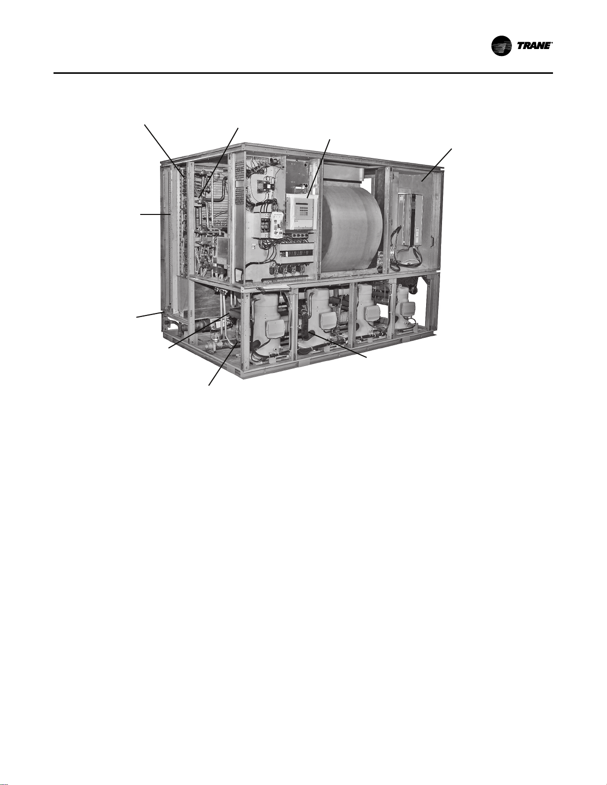
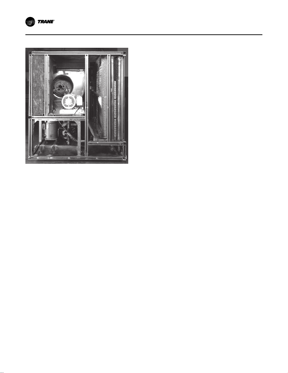
Figure 1. Commercial self-contained signature series unit components
Waterside economizer
(cleanable option shown)
Sight glasses with
ports for viewing
while unit is running
Unit mounted microprocessor
control with easy-to-read human
interface panel
Swing out VFO panel with
Tri-VFO for efficient VAV
operation
Trane 3-D® Scroll Compressor
for reliability, efficiency and
quiet operation
Two-bolt connection on
cleanable condenser for
quick, easy maintenance
Waterside valve
package option
to enhance system
efficiency
Internally trapped
drain for low cost
installation
2-inch flat filter
box inside unit
casing
OOvveerrvviieeww
Standard Controls
Standard controls supplied with the unit include the
human interface (HI) panel with unit control module
(UCM). All basic setup parameters are preset from the
factory.
Human Interface Panel
The HI is unit mounted and accessible without opening
the unit’s front panel. It allows easy setpoint
adjustment using the HI keypad. In addition, the HI
displays all unit operating parameters and conditions
in a clear language display, which can be configured
for either English, French, or Spanish.
The optional remote human interface (RHI) will control
up to four self-contained units, each containing an
interprocessor communications bridge (IPCB). It has all
the same features as the unit-mounted HI except for the
service mode.
For more information on setpoint defaults and ranges
and unit programming, see the Self-Contained
Programming Guide, PKG-SVP01*-EN. A copy ships
with each unit.
Unit Control Module
The UCM provides “smart” unit control with safety
features and control relays for pumps, dampers, etc.
SCXF-SVX01Q-EN
The Signature Series self-contained unit is controlled
by a microelectronic control system that consists of a
network of modules. Modular Series self-contained
unit is controlled by microelectronic control system
consisting of a network of modules.These modules are
referred to as unit control modules (UCM). In this
manual, the acronym UCM refers to the entire control
system network.
These modules perform specific unit functions using
proportional/integral control algorithms. They are
mounted in the unit control panel and are factory wired
to their respective internal components. Each module
receives and interprets information from other unit
modules, sensors, remote panels, and customer binary
contacts to satisfy the applicable request; i.e.,
economizing, mechanical cooling, heating, ventilation.
See the Owner’s section of this manual for a detailed
description of each module’s function.
9
Page 10
OOvveerrvviieeww
Figure 2. Right side view of unit Optional Controls
Optional controls include a disconnect switch, dirty
filter switch, water flow switch (water-cooled only),
supply air temperature reset, or external setpoint
inputs. Daytime heating is available on units with
electric, steam, or hot water heat control options.
Morning warm-up operation is available on all units.
The static pressure probe, zone night heat/morning
warm-up, supply air temperature reset sensor options
ship separate inside the unit control panel for field
installation. For more detailed information on the unit
control options, see the Owner’s section of this
manual.
Unit Nameplate
The unit nameplate identifies the unit model number,
appropriate service literature, and wiring diagram
numbers. It is mounted on the left end of the unit
control panel.
10
SCXF-SVX01Q-EN
Page 11

Model Number Description
Commercial Self-Contained Signature Series
Digit 1 — Unit Model
S = Self-Contained
Digit 2 — Unit Type
C = Commercial
I = Industrial
Digit 3 — Condenser Medium
W = Water-cooled
R = Air-cooled
Digit 4 — Development Sequence
F = Signature Series
Digit 5— Refrigerant Circuit
Configuration
U = Standard Capacity
V = High Capacity
Digit 6, 7 — Unit Nominal Capacity
20 = 20 Tons (water only)
22 = 22 Tons (water only)
25 = 25 Tons (water or air)
29 = 29 Tone (water or air)
30 = 30 Tons (air only)
32 = 32 Tons (water only)
35 = 35 Tons (water or air)
38 = 38 Tons (water only)
40 = 40 Tons (air only)
42 = 42 Tons (water only)
46 = 46 Tons (water only)
50 = 50 Tons (air only)
52 = 52 Tons (water only)
58 = 58 Tons (water only)
60 = 60 Tons (air only)
65 = 65 Tons (water only)
72 = 72 Tons (water only)
80 = 80 Tons (water only)
90 = 90 Tons (water only)
C0 = 100 Tons (water only)
C1 = 110 Tons (water only)
Digit 8 — Unit Voltage
6 = 200 volt/60 hz/3 ph
4 = 460 volt/60 hz/3 ph
5 = 575 volt/60 hz/3 ph
Digit 9 — Air Volume/Temp Control
2 = VFD and supply air temp ctrl
3 = VFD w/ bypass and supply air temp ctrl
4 = Constant volume, zone temp cool only
5 = Constant volume, w/ zone temp heat/
cool
6 = Constant volume and supply air temp ctrl
Digit 10, 11 — Design Sequence
** = Factory Assigned
Digit 12 — Unit Construction
A = Vertical discharge
B = Vertical discharge with double wall
Digit 13— Flexible Horizontal
Discharge Plenum Type
B = STD plenum w/ factory-cut holes
C = Low plenum w/ factory-cut holes
E = Std plenum w/ field-cut holes
F = Low plenum w/ field-cut holes
H = STD plenum double wall w/ field-cut
holes
J = Low plenum double wall w/ field-cut holes
K = Extended height plenum w/factory-cut
holes, ship separate
L = STD plenum w/factory-cut holes, ship
separate
M = Low plenum w/factory-cut holes, ship
separate
N = Extended height plenum w/field-cut
holes, ship separate
P = STD plenum w/field-cut holes, ship
separate
R = Low plenum w/field-cut holes, ship
separate
T = Extended height double-wall plenum w/
field-cut holes, ship separate
U = STD double-wall plenum w/field-cut
holes, ship separate
V = Low double-wall plenum w/field-cut
holes, ship separate
W = STD double-wall (perf) plenum w/fieldcut holes (90 to110 ton only)
X = Low double-wall (perf) plenum w/field-
cut holes (90 to 110 ton only)
Y = Extended height double-wall (perf)
plenum w/field-cut holes, ship separate (90
to 110 ton only)
0 = None
Digit 14— Motor Type
2 = ODP motor
4 = TEFC motor
Digit 15, 16 — Motor HP
05 = 5 hp
07 = 7.5 hp
10 = 10 hp
15 = 15 hp
20 = 20 hp
25 = 25 hp
30 = 30 hp
40 = 40 hp
50 = 50 hp (460V, 575V only)
60 = 60 hp (90 to 110 ton only)
Digit 17, 18, 19 – Fan RPM
040 = 400 rpm
045 = 450 rpm
050 = 500 rpm
052 = 525 rpm
055 = 550 rpm
057 = 575 rpm
060 = 600 rpm
065 = 650 rpm
070 = 700 rpm
075 = 750 rpm
080 = 800 rpm
085 = 850 rpm
090 = 900 rpm
095 = 950 rpm
100 = 1000rpm
105 = 1050 rpm
110 = 1100 rpm
115 = 1150 rpm
120 = 1200 rpm
125 = 1250 rpm
130 = 1300 rpm
135 = 1350 rpm
Digit 20 — Unit Isolators
A = Steam coil
B = Hot water coil
C = Electric heat, 1 stage
D = Electric heat, 2 stage
F = Hydronic heat ctrl interface
G = Electric heat ctrl interface
K = Steam coil ship separate, LH
L= Hot water coil ship separate, LH
T = Hot water coil, high capacity, LH
U = Hot water coil, high capacity, LH, ship
separate
0 = None
Digit 21 — Unit Isolators
A = Isopads
B = Spring isolators
0 = None
Digit 22— Unit Finish
1 = Paint - Slate Gray
Digit 23— Supply Fan Options
0 = Standard fan
1 = Low CFM fan
Digit 24— Unit Connection
1 = Disconnect switch
2 = Terminal block
3 = Dual point power (2 blocks)
SCXF-SVX01Q-EN
11
Page 12

MMooddeell NNuummbbeerr DDeessccrriippttiioonn
Digit 25— Industrial Options
A = Protective coating evaporator coil
B = Silver solder
C = Stainless steel screws
D = A and B
E = A and C
F = B and C
G = A, B, and C
0 = none
Digit 26 — Drain PanType
A = Galvanized sloped
B = Stainless steel sloped
Digit 27 — Waterside Economizer
A = Mechanical clean full capacity (4-row)
B = Mechanical clean low capacity (2-row)
C = Chemical clean full capacity (4-row)
D = Chemical clean low capacity (2-row)
0 = None
Digit 28 — Ventilation Control
B = Airside econ w/Traq damper, top O/A
C = Airside econ w/ std damper, top O/A
E = Airside econ w/Traq damper &
comparative enthalpy, top O/A
F = Airside econ w/ std damper &
comparative enthalpy, top O/A
H = 2-position damper ventilation interface
J = Airside economizer interface
K = Airside economizer interface w/
comparative enthalpy
Digit 29 — Water Piping
D = Left hand basic piping
F = Left hand Intermediate piping
K = Left hand basic w/ flow switch
M = Left hand intermediate w/ flow switch
0 = None
Digit 30 — Condenser Tube Type
A = Standard condenser tubes
B = 90/10 CuNi condenser tubes
0 = None (air-cooled only)
Digit 31 — Compressor Service Valves
1 = With service valves
0 = None
Digit 32— Miscellaneous System
Control
1 = Time clock
2 = Interface for remote HI (IPCB)
3 = Dirty filter switch
4 = 1 and 2
5 = 1 and 3
6 = 2 and 3
7 = 1, 2 and 3
0 = None
Digit 33 — Control Interface Options
A = Generic BAS Module; 0-5 VDC (GBAS)
B = Ventilation Override Module (VOM)
D = Remote Human Interface (RHI)
G = GBAS and VOM
H = GBAS and RHI
J = VOM and RHI
M = GBAS, VOM, and RHI
N = BACnet Communications Interface (BCI)
P = BCI and GBAS
Q = BCI and VOM
R = BCI and RHI
T = BCI and GBAS and VOM
U = BCI and GBAS and RHI
V = BCI and VOM and RHI
W = BCI and GBAS and VOM and RHI
0 = None
1 = Lontalk Comm5 Interface (LCI)
2 = LCI and GBAS
3 = LCI and VOM
4 = LCI and RHI
5 = LCI and GBAS and VOM
6 = LCI and GBAS and RHI
7 = LCI and VOM and RHI
8 = LCI and GBAS and VOM and RHI
Digit 34— Agency
U = UL agency listing
0 = None
Digit 35— Filter Type
1 = 2” T/A w/ 2” rack
2 = 2” med. eff. T/A w/ 2” rack
3 = 4” bolt-on rack w/ 2” med eff. filter
4 = 6” rack w/ 2” construction T/A pre-filter &
4” filter space
5 = 6” rack w/ 2” med. eff. T/A pre-filter & 4”
filter space
Digit 36— Miscellaneous Control
Option
A = Low entering air temp. protect device
(LEATPD)
B = High duct temp t-stat, ship separate
C = Plenum high static switch, ship separate
E = A and B
F = A and C
H = B and C
L = A, B, and C
0 = None
12
SCXF-SVX01Q-EN
Page 13

Commercial Self-Contained Air-Cooled Condenser
MMooddeell NNuummbbeerr DDeessccrriippttiioonn
Digit 1 — Unit Model
C = Condenser
Digit 2 — Unit Type
C = Commercial
I = Industrial
Digit 3 — Condenser Medium
R = Remote
Digit 4 — Development Sequence
C = C
Digit 5, 6, 7 — Nominal Capacity
020 = 20 Tons
029 = 29 Tons
035 = 35 Tons
040 = 40 Tons
050 = 50 Tons
060 = 60 Tons
Digit 8 — Unit Voltage
4 = 460 Volt/60 Hz/3 ph
5 = 575 Volt/60 Hz/3 ph
6 = 200 Volt/60 Hz/3 ph
Digit 12 — Unit Finish
1 = Paint — Slate Gray
Digit 13— Coil Options
A = Non-Coated Aluminum
C = Protective Coating Aluminum
Digit 14— Unit Isolators
0 = None
A = Spring Isolators
B = Isopads
Digit 15— Panels
1 = Louvered Panels
Digit 16— Agency
0 = None
U = With UL Listing
Digit 9 — Control Option
0 = No Low Ambient, IPak
A = No Low Ambient, T-Stat*
B = Low Ambient, IPak
C = Low Ambient, T-Stat*
Note: *T-Stat only available on SCRG.
Digit 10, 11— Design Sequence
** = Factory Assigned
SCXF-SVX01Q-EN
13
Page 14
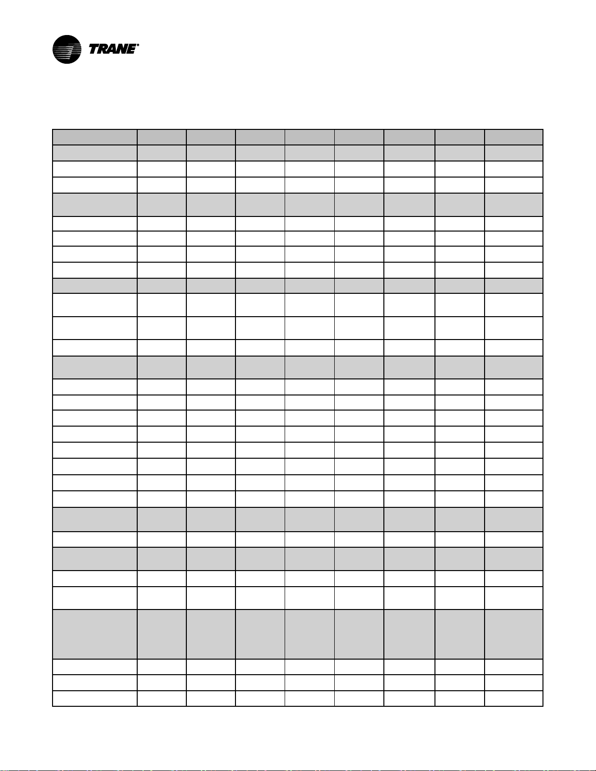
General Data
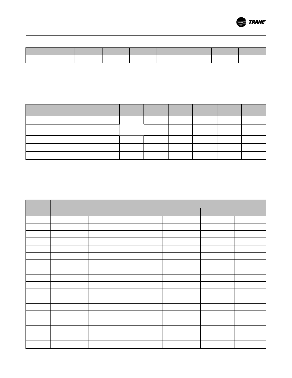
Table 1. SCWF/SIWF Water-cooled self-contained, 20 to 42 tons
Unit Size 20 22 25 29 32 35 38 42
Compressor Data
Quantity
Nominal Ton/comp
Evaporator Coil
Data
Circuits 2 2 2 2 2 3 3 3
Rows 2 2 3 or 6 2 4 or 6 3 4 or 6 3
Sq. Ft.
Fpf
Condenser Data
Minimum Gpm w/o
Econ
Minimum Gpm w/
Econ
Maximum Gpm
Evaporator Fan
Data
Quantity
Diameter 18" 18" 18" 18" 18" 20" 20" 25"
Minimum Hp
Minimum Kw
Maximum Hp
Maximum Kw
Minimum Design Cfm
Maximum Design Cfm
High Capacity
Option
Rows
Optional Low Flow
Fan 6
Diameter
Min/max Design Cfm
Refrigerant Charge,
lbs. R-410A
(Standard
Capacity/High
Capacity)
Circuit A 19.5 19.5 21.5 24.7
Circuit B 19.5 19.5 21.5 20.5
Circuit C
2 2 2
10 10 10
21.81 21.81 21.81 29.98 29.98 31.35 31.35 38.57
144 144 144 144 144 144 144 144
36 36 36 46 46 54 54 64
41 41 41 60 60 65 65 64
80 80 80 102 102 119 119 142
1 1 1 1 1 1 1 1
5 5 5 5 5 5 5 7. 5
(3.73) (3.73) (3.73) (3.73) (3.73) (3.73) (3.73) (5.39)
20 20 20 20 20 25 25 30
(14.91) (14.91) (14.91) (18.64) (18.64) (18.64) (18.64) (22.37)
6325 6325 6500 8700 8700 9100 9880 11200
8500 9350 10625 12325 13600 14875 16150 17850
N/A N/A
N/A N/A N/A N/A N/A N/A
N/A N/A N/A N/A N/A N/A
N/A N/A N/A N/A N/A
6
1/1 1/1
15/10 15/10
N/A
6
28.5/29.3
23.5/23.5
3 3
10 10
N/A
21.5
21.5
21.5
23.5/26.5
23.5/26.5
23.5/26.5
6
18”
6000/
10625
2/1
10/15
N/A
N/A
N/A
22.0
22.0
22.0
14
SCXF-SVX01Q-EN
Page 15
GGeenneerraall DDaattaa
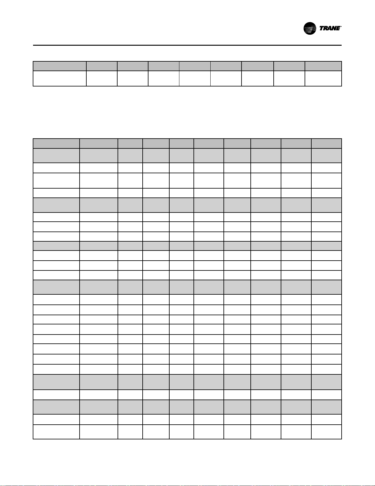
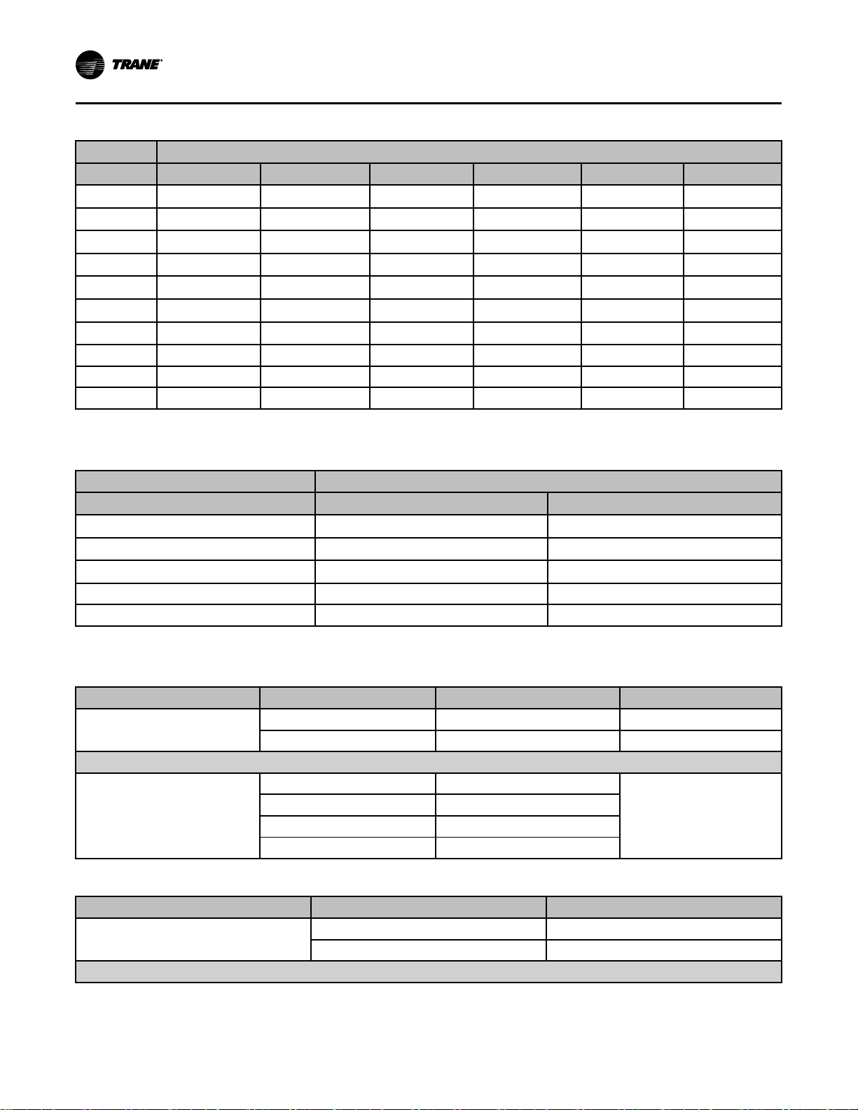
Table 1. SCWF/SIWF Water-cooled self-contained, 20 to 42 tons (continued)
Unit Size 20 22 25 29 32 35 38 42
Capacity Steps - %
Notes:
1. Compressors are Trane 3-D™ scroll.
2. All units operate with R-410A. Units ships with full operating charge.
3. Maximum cfm limits are set to prevent moisture carryover on the evaporator coil.
4. Minimum cfm limits are set to ensure stable thermal expansion valve operation at low load conditions.
5. Optional low flow fan (unit model number digit 23 = 1) is available ONLY when High Capacity option is selected (unit model number digit 5 = V).
100/53/0 100/53/0 100/53/0
Table 2. SCWF/SIWF Water-cooled self-contained, 46-110 tons
Unit Size 46 52 58 65 72 80 90 100 110
Compressor
Data
Quantity
Nominal Ton/
Comp
Circuits 3 3 3 4 4 4 5 6 6
Evaporator Coil
Data
Rows 4 or 6 2 4 or 6 3 4 or 6 6 6 or 8 6 or 8 6 or 8
Sq. Ft.
FPF 144 144 144 144 144 144 144 144 144
Condenser Data
Min GPM w/o Econ
Min GPM w/ Econ
Maximum GPM 142 186 186 226 226 248 300 350 350
Evaporator Fan
Data
Quantity
Size (Dia.)
Minimum HP 7.5 7.5 7.5 10 10 10 15 15 15
Minimum kW
Maximum HP 30 40 40 50 50 50 60 60 60
Maximum kW
Min Design CFM
Max Design CFM
High Capacity
Option
Rows 6
Optional Low
Flow Fan
Size (Dia.)
Min./Max Design
CFM
2/1
10/15
38.57 49.09 49.09 49.09 49.09 49.09 56.81 56.81 56.81
64 84 84 102 102 112 140 168 168
64 84 84 102 102 112
1 1 1 1 1 1 1 1 1
25" 25" 25" 27.5" 27.5" 27.5" 27.5" 27.5" 27.5"
(5.59) (5.59) (5.59) (7.46) (7.46) (7.46) (11.19) (11.19) (11.19)
(22.37) (29.84) (29.84) (37.29) (37.29) (37.29) (44.74) (44.74) (44.74)
11960 14250 15080 16900 18700 20800 17500 17500 17500
19550 22100 24650 27625 29800 29800 35000 35000 35000
18"
7700/13600 N/A
3 3
15 15
N/A
N/A
8900/
13600
6
18"
100/62/39/0100/59/39/0100/65/31/0100/65/30/
3/1 3/1
15/10 15/10
N/A
N/A
N/A
6
20"
10700/
16150
4 5
15 15
N/A N/A N/A
N/A
N/A N/A N/A N/A
N/A N/A N/A N/A
8 8 8
0
2/4
10/15
100/71/43/
26/0
6
15
SCXF-SVX01Q-EN
15
Page 16
GGeenneerraall DDaattaa
Table 2. SCWF/SIWF Water-cooled self-contained, 46-110 tons (continued)
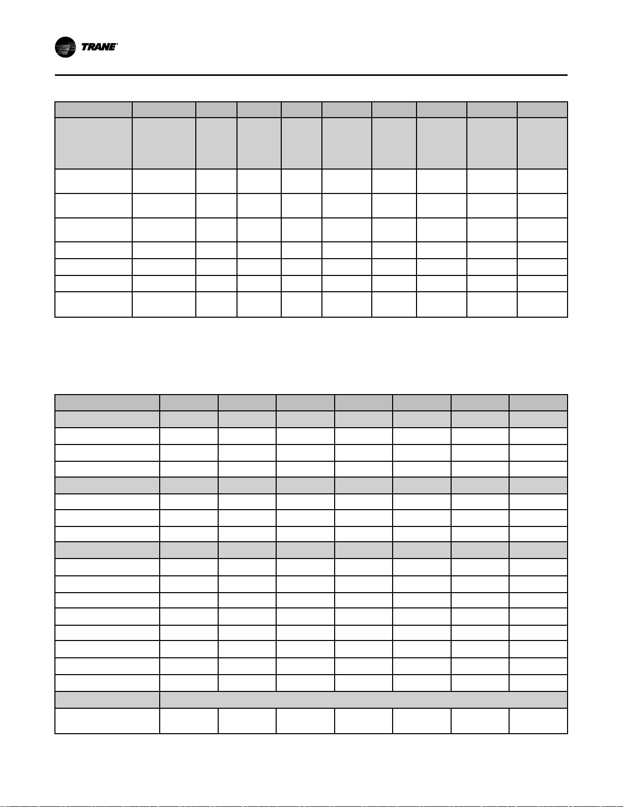
Unit Size 46 52 58 65 72 80 90 100 110
Refrigerant
Charge — lbs. R410A (Standard
Capacity/High
Capacity)
Circuit A
Circuit B
Circuit C
Circuit D
Circuit E
Circuit F
Capacity Steps - %
Notes:
1. Compressors are Trane 3-D™ scroll.
2. All units operate with R-410A. Units ships with full operating charge.
3. Maximum cfm limits are set to prevent moisture carryover on the evaporator coil.
4. Minimum cfm limits are set to ensure stable thermal expansion valve operation at low load conditions.
24.5/28.5
24.5/28.5
24.5/28.5
N/A N/A N/A
N/A N/A N/A N/A N/A N/A
N/A N/A N/A N/A N/A N/A N/A
100/70/41/30/
0
21.0
21.0
21.0
100/65/
32/0
26.5/
31.5
26.5/
31.5
26.5/
31.5
100/65/
30/0
22.0 24.5 28.0 24.5 24.5 24.5
22.0 24.5 28.0 24.5 24.5 24.5
22.0 24.5 28.0 24.5 24.5 24.5
21.0 22.0 28.0 24.5 24.5 24.5
24.5 24.5 24.5
24.5 24.5
100/71/
44/24/0
100/71/
43/23/0
100/73/
46/20/0
100/80/
40/20/0
100/75/
38/19/0
100/66/
33/17/0
Table 3. SCRF/SIRF Air-cooled self-contained
Unit Size 25 29 30 35 40 50 60
Compressor Data
Quantity
Nominal Ton/Comp
Circuits 2 2 2 2 2 2 2
Evaporator Coil Data
Rows 4 4 3 4 4 4 6
Sq. Ft.
FPF 144 144 120 144 144 144 144
Evaporator Fan Data
Quantity
Size (Dia.)
Minimum HP 5 5 5 5 7.5 7.5 10
Minimum kW
Maximum HP 20 20 25 25 30 40 50
Maximum kW
Minimum Design CFM
Maximum Design CFM
Refrigerant Charge
Capacity Steps - %
1/1 1/1
15/10 15/10
29.98 29.98 31.35 31.35 38.57 49.09 49.09
1 1 1 1 1 1 1
18" 18" 20" 20" 25" 25" 27.5"
(3.73) (3.73) (3.73) (3.73) (5.59) (5.59) (7.46)
(18.64) (18.64) (18.64) (18.64) (22.37) (29.84) (37.29)
8700 8700 9100 9880 11960 15080 20800
12325 13600 14875 16150 19550 24650 29800
100/62/39/0 100/59/39/0 100/65/31/0 100/65/30/0
3 3
10 10
See Note 2 below
2/1
10/15
100/70/41/
30/0
15 15
100/65/30/0
3 4
100/73/46/
20/0
16
SCXF-SVX01Q-EN
Page 17
GGeenneerraall DDaattaa
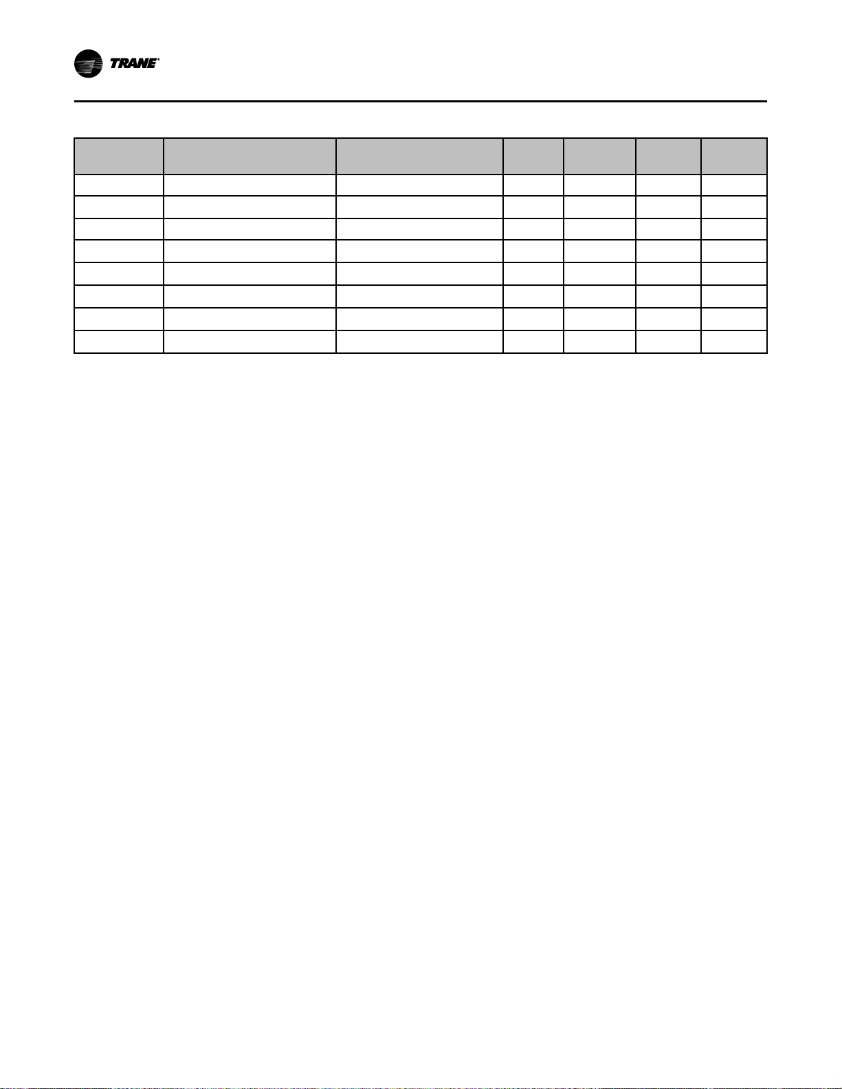
Table 3. SCRF/SIRF Air-cooled self-contained (continued)
Unit Size 25 29 30 35 40 50 60
CCRC/CIRC Unit Match
Notes:
1. Compressors are Trane 3-D™ scroll.
2. All units operate with R-410A. Units ship with a dry nitrogen holding charge. Field refrigerant system charge required. Refer to Table 4, p. 17 for
amounts required.
3. Maximum cfm limits are set to prevent moisture carryover on the evaporator coil.
4. Minimum cfm limits are set to ensure stable thermal expansion valve operation at low load conditions.
Table 4. SCRF/SIRF Air–cooled self–contained and CCRC/CIRC remote air-cooled condenser refrigerant data
29 29 35 35 40 50 60
SCRF/SIRF & CCRC/CIRCUnit
Size
No. of Refrigerant Circuits
Operating Charge - lbs. R-410A
Operating Charge - kg R-410A
Cond. Storage Cap. - lbs. R-410A
Cond. Storage Cap. - kg R-410A
Notes:
1. Refrigerant charges are listed as circuit 1 circuit 2 and provide only an estimate. Final charge requires sound field charging practice.
2. Operating charge is for entire system, which includes the air–cooled self–contained, remote air–cooled condenser, and 25 feet of interconnecting
refrigerant piping.
3. At conditions of 95° F (35° C), condenser storage capacity is 95% full.
4. To determine the correct amount of refrigerant needed for a particular application, reference the Trane Reciprocating Refrigeration Manual.
25/29 29/29 30/35 35/35 40/40 50/50 60/60
2 2 2 2 2 2 2
56.2/38.0 56.2/38.0 71/35.5 75/37.5 86.5/39.5 100/52
23.1/17 23.1/17 32.2/16.1 34/17 39.2/17.9 44.5/22.7 46/46
51/37 51/37 74/37 74/37 74/51 102/51 102/102
23.1/16.8 23.1/16.8 33.6/16.8 33.6/16.8 33.6/23.1 46.3/23.1 46.3/46.3
Table 5. SCWF/SIWF water volumes
Water Volume in U.S. Gallons / Liters
Unit Size
20 9.0 34.1 17.4 65.9 16.9 64.0
22 9.0 34.1 17.4 65.9 16.9 64.0
25 9.0 34.1 17.4 65.9 16.9 64.0
29 9.0 34.1 20.5 77.6 18.8 71.2
32 9.0 34.1 20.5 77.6 18.8 71.2
35 10.0 37.9 21.9 82.9 20.2 76.5
38 10.0 37.9 21.9 82.9 20.2 76.5
42 15.0 56.8 32.2 121.9 31.4 118.9
46 15.0 56.8 32.2 121.9 31.4 118.9
52 15.0 56.8 36.9 139.7 35.9 135.9
58 15.0 56.8 36.9 139.7 35.9 135.9
65 16.0 60.6 37.9 143.5 36.9 139.7
72 16.0 60.6 37.9 143.5 36.9 139.7
80 16.0 60.6 37.9 143.5 36.9 139.7
90 22.5 85.2 50.1 189.6
100 23.0 87.1 50.6 191.5
110 24.0 90.8 51.6 195.3
W/o Economizer
Gallons Liters Gallons Liters Gallons Liters
With Mech. Cleanable Econ With Chem. Cleanable Econ
N/A N/A
N/A N/A
N/A N/A
101.5/
101.5
SCXF-SVX01Q-EN
17
Page 18
GGeenneerraall DDaattaa
Table 6. SCWF/SIWF Refrigerant circuits, number of compressors by circuit
Circuit
Unit Size 1 2 3 4 5 6
20/22/25 Ton
29/32 Ton
35/38 Ton
42/46 Ton
52/58 Ton
60/72 Ton
80 Ton 1- 15T 1- 15T 1- 15T 1- 15T
90 Ton 1- 15T 1- 15T 1- 15T 1- 15T 1- 15T
100 Ton 1-15T 1-15T 1-15T 1-15T 1-10T 1-10T
110 Ton 1- 15T 1- 15T 1- 15T 1- 15T 1- 15T 1- 15T
Note: This table depicts compressor location in unit, plan view from left corner.
1- 10T 1- 10T
1- 15T 1- 10T
1- 10T 1- 10T 1- 10T
1- 15T 1- 10T 1- 10T
1- 15T 1- 15T 1- 15T
1- 15T 1- 15T 1- 15T 1- 10T
Table 7. SCRF/SIRF Refrigerant circuits, number of compressors by circuit
Unit Size 1 2
25/29 Ton
30/35 Ton
40 Ton
50 Ton 2-15T 1-15T
60 Ton 2-15T 2-15T
Note: This table depicts compressor location in unit, plan view from left corner.
N/A N/A N/A N/A
N/A N/A N/A N/A
N/A N/A N/A
N/A N/A N/A
N/A N/A N/A
N/A N/A
N/A N/A
Circuit
1-15T 1-10T
2-10T 1-10T
1-10T, 1-15T
1-10T
Table 8. Filter data, water-cooled units models SCWF & SIWF
Unit Size 20- 38 tons 40-85 tons 90-110 tons
Number - Size (In.)
Number - Size (In.)
8 - 20 x 18 12 - 25 x 20 15 - 24 x 24
4 - 20 x 20 6 - 20 x 20 3 - 24 x 12
Units With Hot Water Or Steam
4 - 16 x 20 4 - 25 x 20
4 - 20 x 20 2 - 20 x 20
4 - 18 x 20 8 - 25 x 16
Table 9. Filter data, air-cooled units models SCRF & SIRF
Unit size 20- 35 tons 40-60 tons
Number - Size (in.)
Units With Hot Water Or Steam
18
8 - 20 x 18 12 - 25 x 20
4 - 20 x 20 6 - 20 x 20
n/a
4 - 20 x 16
SCXF-SVX01Q-EN
Page 19
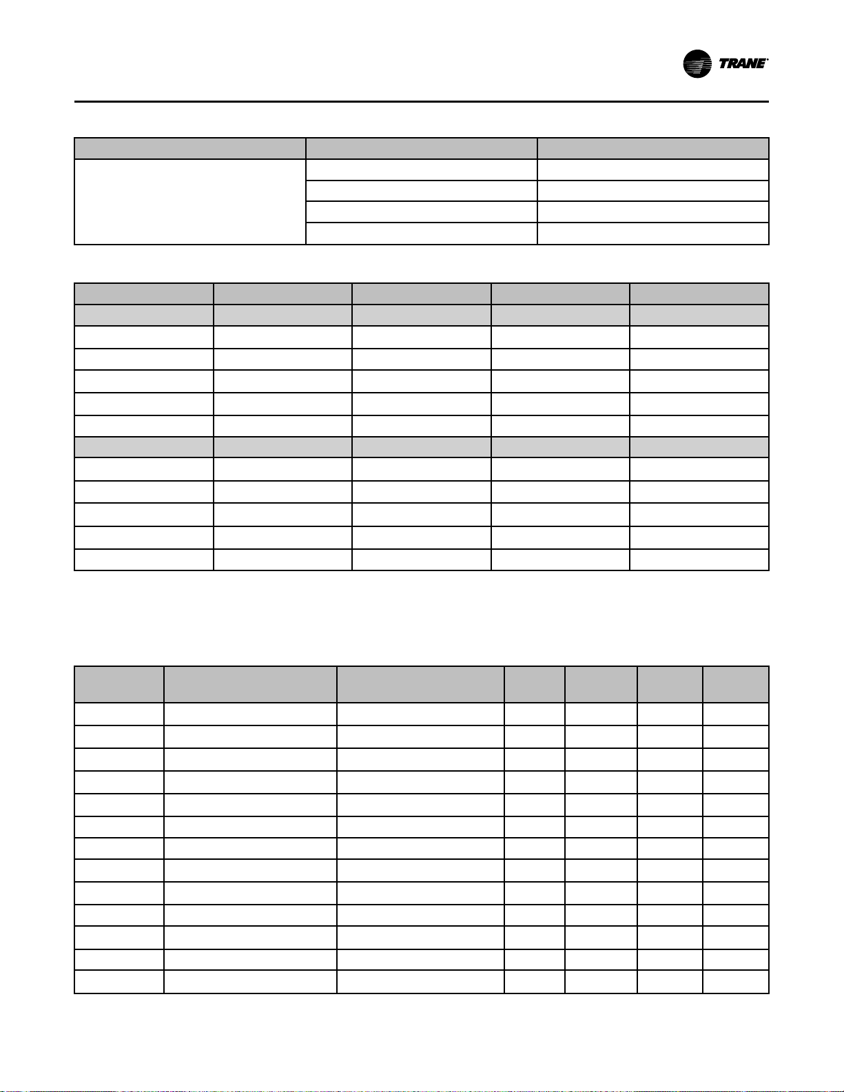
Table 9. Filter data, air-cooled units models SCRF & SIRF (continued)
Unit size 20- 35 tons 40-60 tons
4 - 16 x 20 4 - 25 x 20
Number - Size (in.)
4 - 20 x 20 2 - 20 x 20
4 - 18 x 20 8 - 25 x 16
N/A
4 - 20 x 16
Table 10. Self-contained heating coil
Unit Size SCWF 20 - 38 SCWF 42 - 80 SCRF 20 - 35 SCRF 40 - 60
Steam Coil
Coil Type
Rows 1 1 1 1
No./Size (inches) (2) 24 x 58 (2) 30 x 81 (2) 24 x 58) (2) 30 x 81
No./Size (mm) (2) 609.6 x 1473.2 (2) 762 x 2057.4 (2) 609.6 x 1473.2 (2) 762 x 2057.4
FPF 42 42 42 42
Hot Water Coil
Coil Type
Rows 1 or 2
No./Size (inches) (2) 24 x 58 (2) 30 x 81 (2) 24 x 58 (2) 30 x8 1
No./Size (mm) (2) 609.6 x 1473.2 (2) 762 x 2057.4 (2) 609.6 x 1473.2 (2) 762 x 2057.4
FPF 80 or 108 80 or 108 80 or 108 80 or 108
Notes:
1. Hot water and steam heating coils have Prima-Flo® fins without turbulators.
2. For coil capacities, use TOPSS™ (Trane Official Product Selection Program).
3. Full capacity coils consist of two coils stacked and piped in parallel.
NS NS NS NS
5W 5W 5W 5W
N/A N/A N/A
GGeenneerraall DDaattaa
Table 11. Waterside economizer coil physical data
Model Unit Size
SCXF
SCXF
SCXF
SCXF
SCXF 29 & 32
SCXF 29 & 32 Mechanical Cleanable 2 108 55 78.5
SCXF 29 & 32 Mechanical Cleanable 4 108 55 78.5
SCXF 29 & 32
SCXF 35 & 38
SCXF 35 & 38 Mechanical Cleanable 2 108 57.5 78.5
SCXF 35 & 38
SCXF 35 & 38 Mechanical Cleanable 4 108 57.5 78.5
SCXF 42 & 46
20, 22 & 25 Chemically Cleanable
20, 22 & 25
20, 22 & 25 Chemically Cleanable
20, 22 & 25
Type
Mechanical Cleanable 2 108 40 78.5
Mechanical Cleanable 4 108 40 78.5
Chemically Cleanable
Chemically Cleanable
Chemically Cleanable
Chemically Cleanable
Chemically Cleanable
Rows FPF
2 108 40 78.5
4 108 40 78.5
2 108 55 78.5
4 108 55 78.5
2 108 57.5 78.5
4 108 57.5 78.5
2 144 55 101
SCXF-SVX01Q-EN
Height
(in)
Length
(in)
19
Page 20
GGeenneerraall DDaattaa
Table 11. Waterside economizer coil physical data (continued)
Model Unit Size
SCXF 42 & 46 Mechanical Cleanable 2 144 70 101
SCXF 42 & 46
SCXF 42 & 46 Mechanical Cleanable 4 144 70 101
SCXF
SCXF
SCXF
SCXF
SCXF
52, 58, 65, 72, 80, 85 Chemically Cleanable
52, 58, 65, 72, 80, 85
52, 58, 65, 72, 80, 85 Chemically Cleanable
52, 58, 65, 72, 80, 85
90, 100 & 110
Type
Chemically Cleanable
Mechanical Cleanable 2 144 70 101
Mechanical Cleanable 4 144 70 101
Mechanical Cleanable 4 144 70 119.3
Rows FPF
4 144 55 101
2 144 70 101
4 144 70 101
(in)
Height
Length
(in)
20
SCXF-SVX01Q-EN
Page 21

Pre-Installation
Receiving
Receiving Checklist
Complete the following checklist immediately after
receiving unit shipment to detect possible shipping
damage:
• Inspect individual cartons before accepting. Check
for rattles, bent carton corners, or other visible
indications of shipping damage.
• If a unit appears damaged, inspect it immediately
before accepting the shipment. Make specific
notations concerning the damage on the freight bill.
Do not refuse delivery.
• Inspect the unit for concealed damage before it is
stored and as soon as possible after delivery.
Report concealed damage to the freight line within
the allotted time after delivery. Check with the
carrier for their allotted time to submit a claim.
• Do not move damaged material from the receiving
location. It is the receiver’s responsibility to provide
reasonable evidence that concealed damage did
not occur after delivery.
• Do not continue unpacking the shipment if it
appears damaged. Retain all internal packing,
cartons, and crate. Take photos of damaged
material if possible.
• Notify the carrier of the damage immediately by
phone and mail. Request an immediate joint
inspection of the damage by the carrier and
consignee.
NNoottee:: Notify your Trane representative of the damage
and arrange for repair. Have the carrier inspect
the damage before making any repairs to the
unit.
Ship-Separate Accessories
Field-installed sensors ship separately inside main
control panel of the unit. Extra filters, sheaves, and
belts ship in the fan motor section of the unit.
Condenser plugs, spring isolators, and Iso-pads ship
stored in the bottom left side of the unit.
Contractor Installation Responsibilities
Complete the following checklist before beginning final
unit installation:
• Verify the unit size and tagging with the unit
nameplate.
• Make certain the floor or foundation is level, solid,
and sufficient to support the unit and accessory
weights. Level or repair the floor before positioning
the unit if necessary.
• Allow minimum recommended clearances for
routine maintenance and service. Allow space at
end of the unit for shaft removal and servicing.
Refer to the unit submittals for dimensions. See
also the “Service Clearances” section in the
Dimensional Data chapter.
• Allow three fan diameters above the unit for the
discharge ductwork. Return air enters the rear of
the unit and conditioned supply air discharges
through the top.
• Electrical connection knockouts are on the top, left
side of the unit.
• Allow adequate space for piping access and panel
removal. Condenser water piping, refrigerant
piping, and condensate drain connections are on
the lower left end panel.
NNoottee:: Unit height and connection locations will
change if using vibration isolators. The unit
height may increase up to 5-7/8” with spring
type isolators.
• Electrical supply power must meet specific balance
and voltage requirements as described in chapter
“Electrical Installation”.
• Water-cooled units only: The installer is responsible
for providing a condenser main, standby water
pump, cooling tower, pressure gauges, strainers,
and all components for waterside piping. See
“Water Piping,” p. 38 for general waterside
recommendations.
• Air-cooled units only: The installer is responsible
for providing and installing the remote air-cooled
condenser and refrigerant piping.
Unit Inspection
To protect against loss due to damage incurred in
transit, perform inspection immediately upon receipt of
the unit.
Exterior Inspection
If the job site inspection reveals damage or material
shortages, file a claim with the carrier immediately.
Specify the type and extent of the damage on the bill of
lading before signing. Notify the appropriate sales
representative.
IImmppoorrttaanntt:: Do not proceed with installation of a
damaged unit without sales
representative’s approval.
• Visually inspect the complete exterior for signs of
shipping damages to unit or packing material.
• Verify that the nameplate data matches the sales
order and bill of lading.
• Verify that the unit is properly equipped and there
are no material shortages.
• Verify that the power supply complies with the unit
nameplate specifications.
SCXF-SVX01Q-EN
21
Page 22
Shipping Cover
PPrree--IInnssttaallllaattiioonn
Inspection for Concealed Damage
Visually inspect the components for concealed damage
as soon as possible after delivery and before it is
stored.
If concealed damage is discovered:
• Notify the carrier’s terminal of the damage
immediately by phone and by mail.
• Concealed damage must be reported within 15
days.
• Request an immediate, joint inspection of the
damage with the carrier and consignee.
• Stop unpacking the unit.
• Do not remove damaged material from receiving
location.
• Take photos of the damage, if possible.
Figure 3. Typical unit shipping package
• The owner must provide reasonable evidence that
the damage did not occur after delivery.
Repair
Notify the appropriate sales representative before
arranging unit installation or repair.
IImmppoorrttaanntt:: Do not repair unit until the damage has
been inspected by the carrier’s
representative.
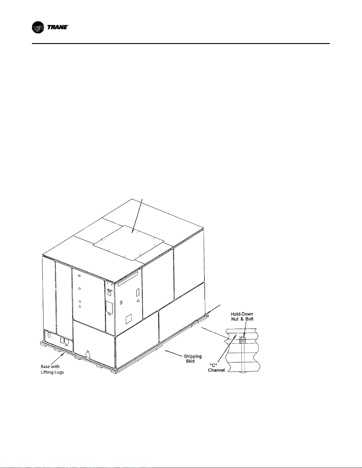
Unpacking
Commercial self-contained units ship assembled with
protective coverings over the coil and discharge
openings.Figure 3, p. 22 illustrates a typical shipping
package.
22
SCXF-SVX01Q-EN
Page 23
PPrree--IInnssttaallllaattiioonn
Unit Protective Covers
Remove shipping protection coverings from human
interface panel (HI) at control panel, filter box (or air
inlet opening), discharge air opening, and optional
variable frequency drive (VFD).
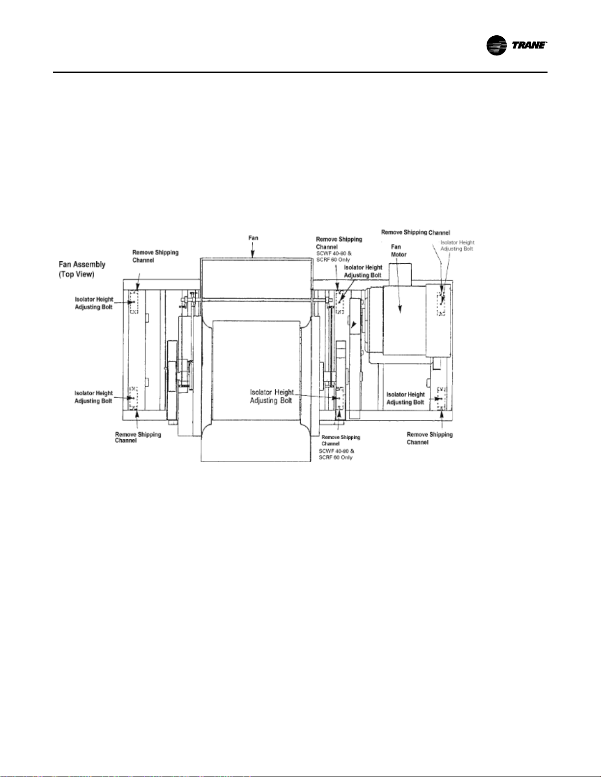
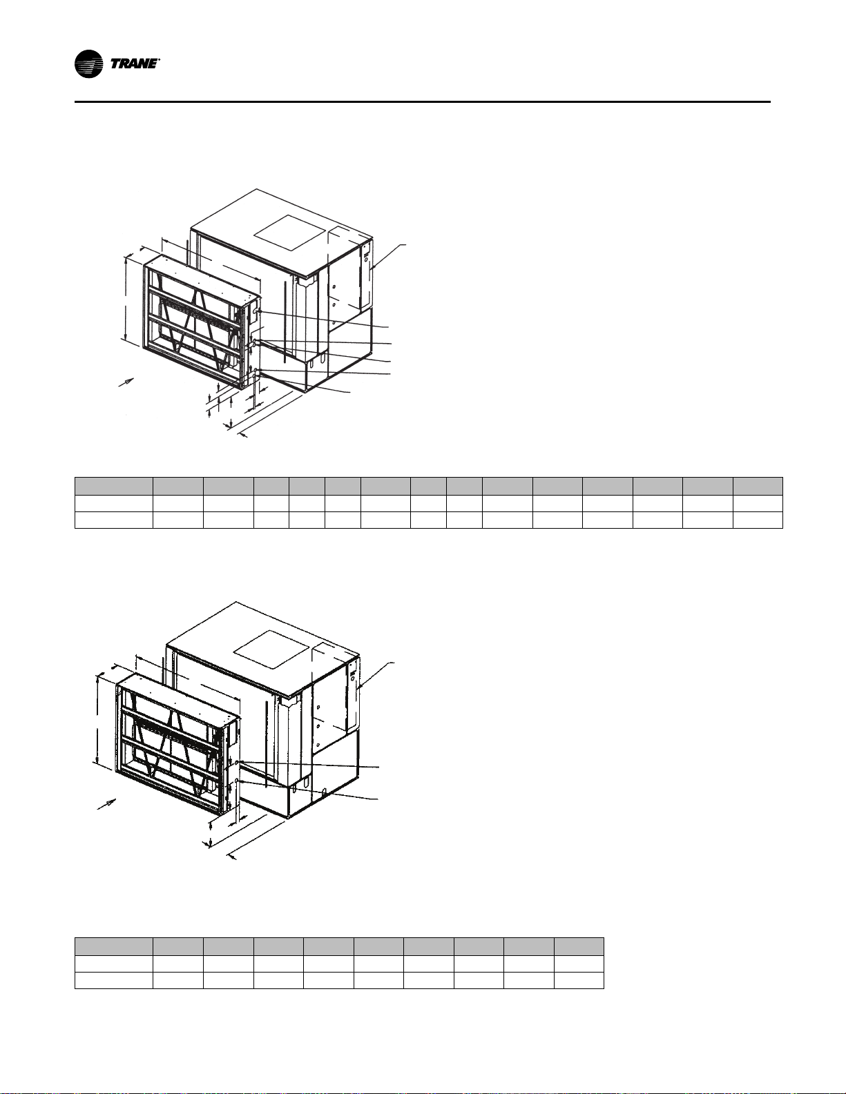
Supply Fan Isolators
Remove the shipping channels and four fan mounting
bolts from beneath the fan. Open both fan
compartment doors to access the channels.
Figure 4. Fan Assembly Shipping Spacer Locations
NNootteess::
• There are six fan mounting points for 40-110
ton units.
• The 20 to 38 ton units use neoprene
isolators, and 40 to 110 ton units use spring
isolators.
SCXF-SVX01Q-EN
23
Page 24
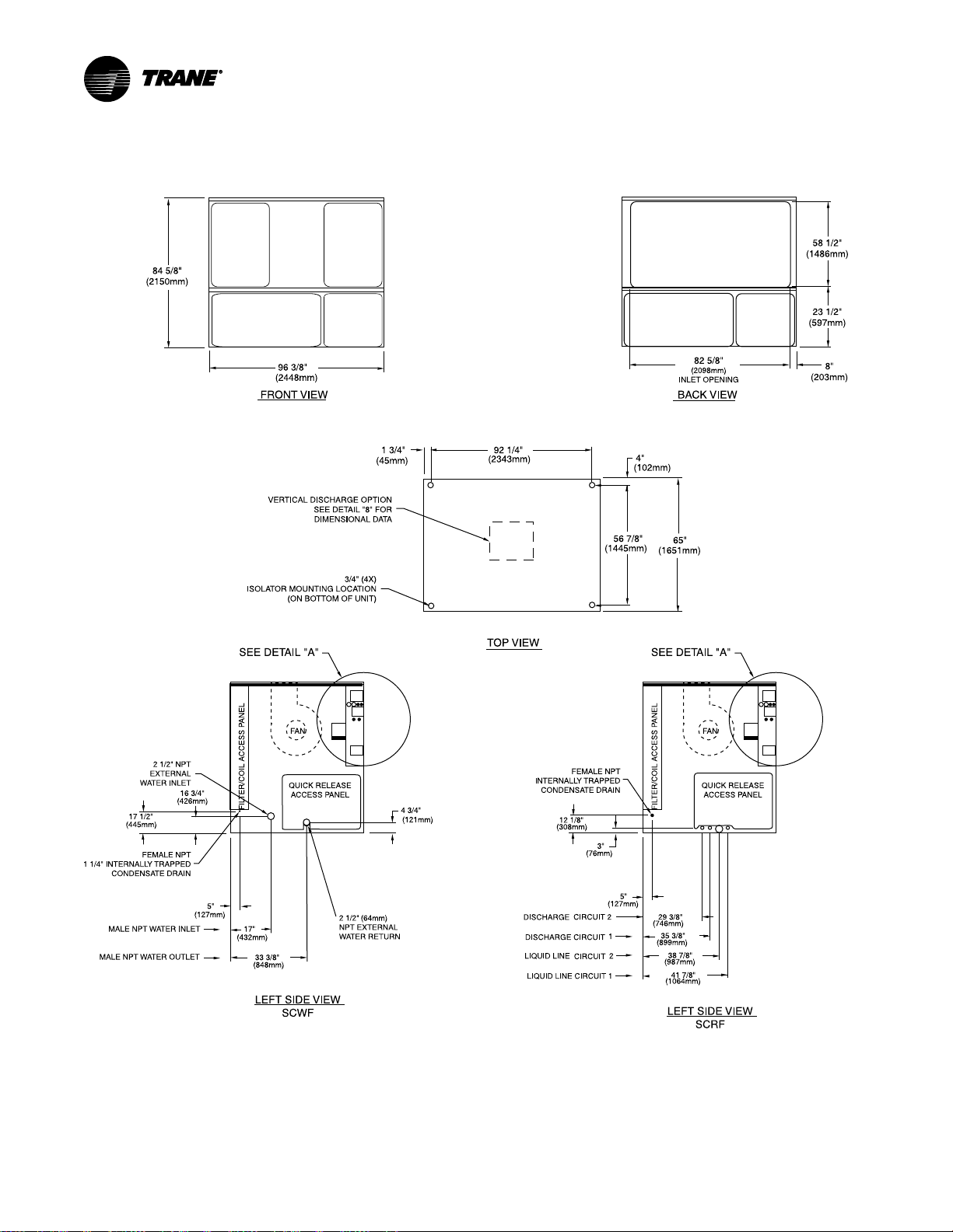
Dimensional Data
Figure 5. 20 to 38 ton self-contained
NNootteess::
24
1. All unit weights include refrigerant, water, controllers, electric heat and valves.
2. Add 150 lbs. to total weight to obtain approximate shipping weight.
SCXF-SVX01Q-EN
Page 25
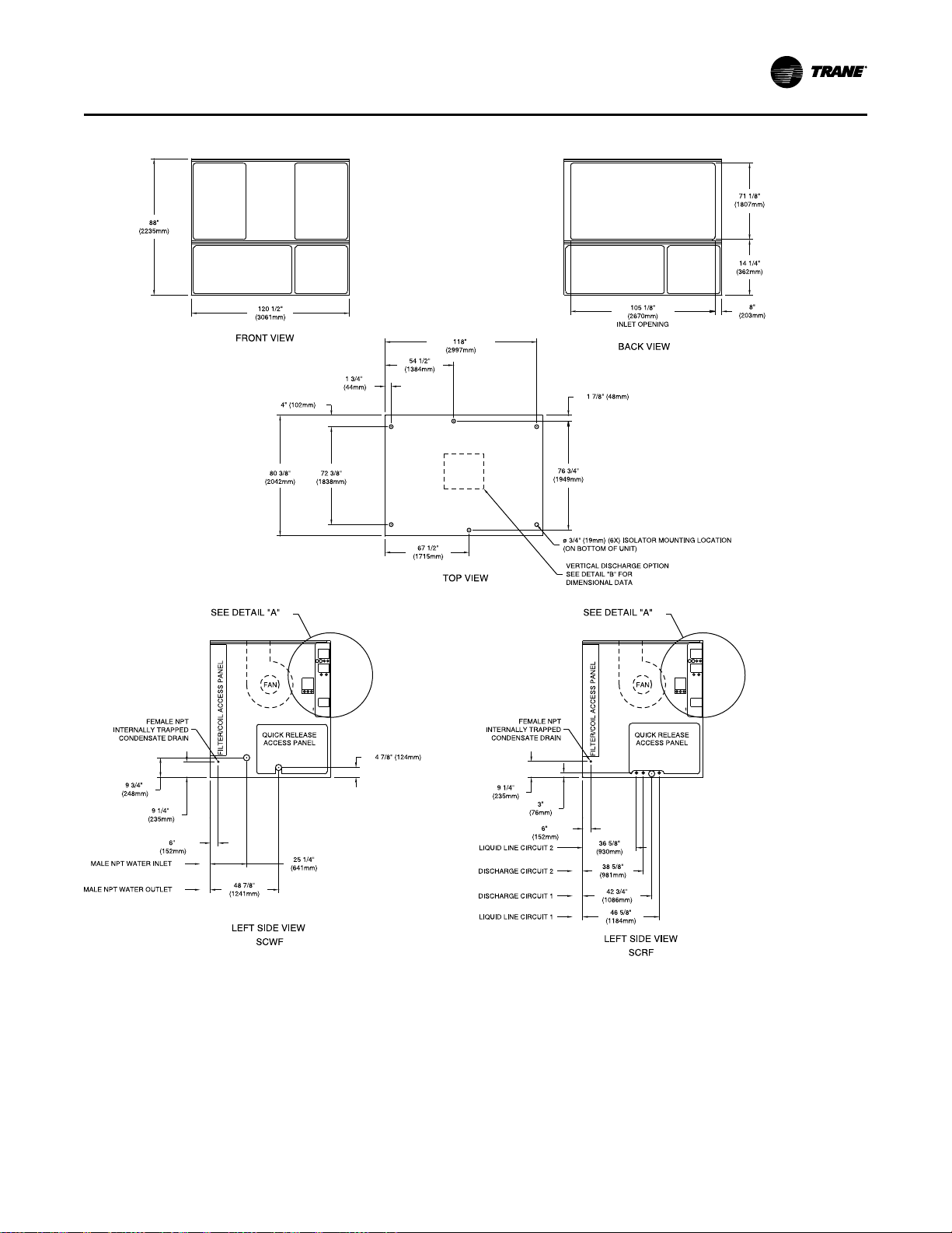
Figure 6. 42 to 80 ton self-contained
DDiimmeennssiioonnaall DDaattaa
NNootteess::
1. All unit weights include refrigerant, water, controllers, electric heat and valves.
2. Add 150 lbs. to total weight to obtain approximate shipping weight.
SCXF-SVX01Q-EN
25
Page 26
Ext. Height
Std. Height
Low Height
43.50"
27.75"
19.625"
Human
Interface
89.50"
Unit Control
Box
140.00"
VFD/
Interface
Plenum (low, standard,
and extended height shown)
72.00"
3.50"
133.00"
69.75"
3.50"
Filter Rack
*
*
*
*
*
*
Isolator Mounting Location (x6)
on bottom of unit
80.50”
86.25”
DDiimmeennssiioonnaall DDaattaa
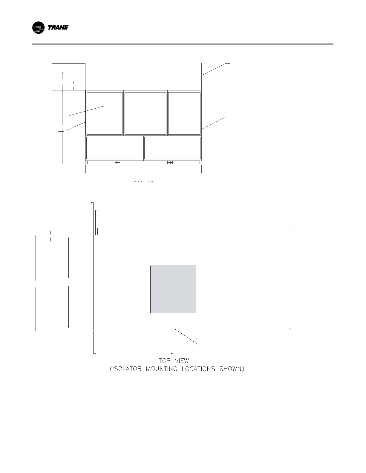
Figure 7. 90 to 110 ton self-contained: front view
Figure 8. 90 to 110 ton self-contained: top view (isolator mounting locations shown)
26
SCXF-SVX01Q-EN
Page 27
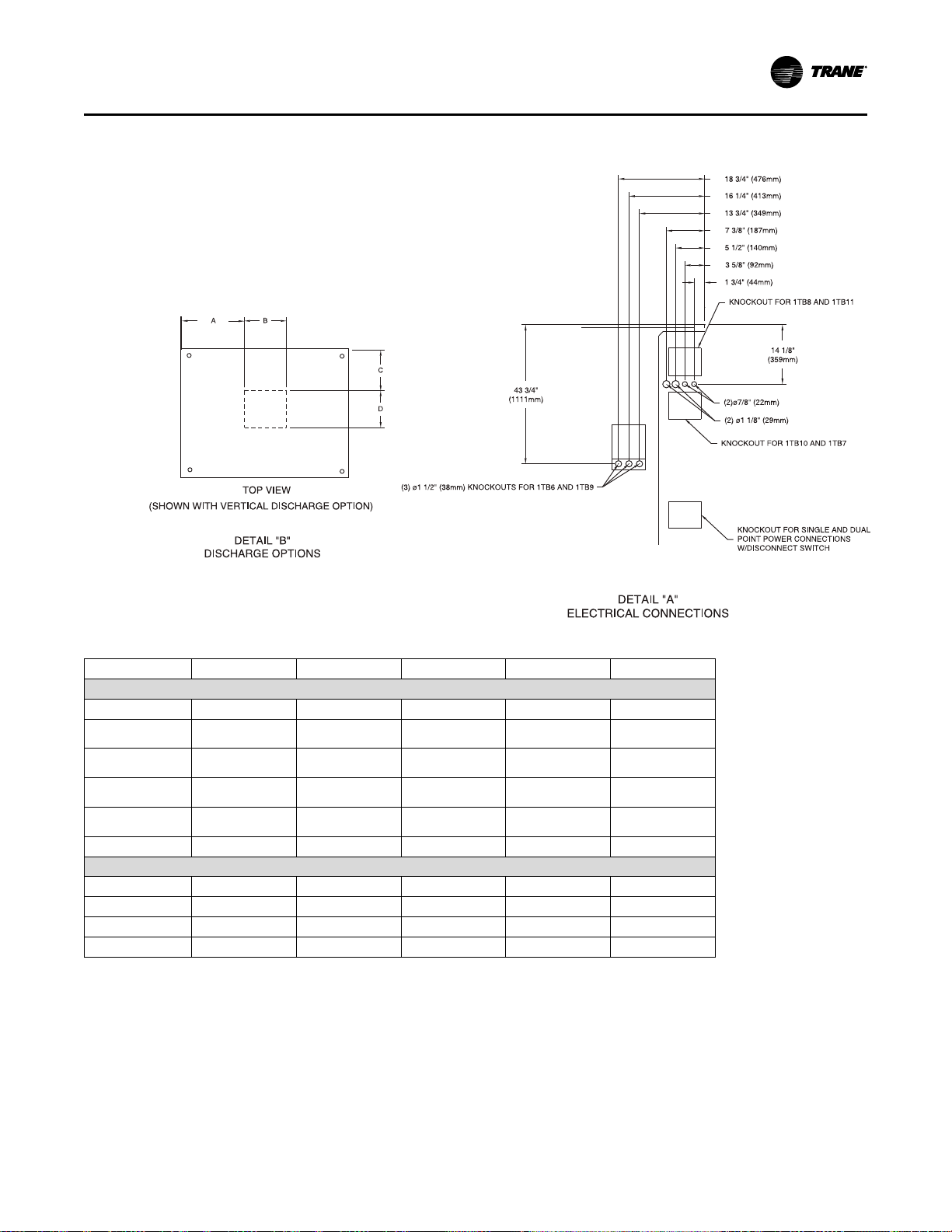
Figure 9. Detail A: electrical connections 20 to 110 tons
40 3/8” (20-38 Ton)
PLUGS
PLUGS
DDiimmeennssiioonnaall DDaattaa
Table 12. Discharge dimensions (in.)
Unit Model Fan Size A B C D
Standard Fan
SCWF 20-25 18” 31.85 23.5 23.11 20.4
SCWF 29-32
SCRF 25-29
SCWF 35-38
SCRF 30-35
SCWF 42-58
SCRF 40-50
SCWF 65-80
SCRF 60
SCWF 90-110 27.5” 50.7 33.5 28.8 34.5
SCWF 38 18” 44.8 23.25 36.78 19
SCWF 46 18” 44.8 23.25 36.78 19
SCWF 58 18” 44.8 23.25 36.78 20.4
SCWF 72 20” 43.4 26.2 34.77 24.6
18” 31.85 23.5 23.11 20.4
20” 30.5 26.2 21.25 25.75
25” 43.75 33 31.5 31.5
27.5” 43.5 33.5 28.63 34.5
Low Flow Fan Option
SCXF-SVX01Q-EN
27
Page 28
Main Control Panel
Vacuum Trap Connection
Condensate Return
Vacuum Trap Connection
Steam Inlet Connection
Condensate Return
Air Inlet
L
K
F
N
M
H
J
A
C
B
Notes:
1. All coils are factory mounted, piped, and wired.
2. All piping connections are 1-1/2” (38.1mm) female NPT fittings.
Main Control Panel
Air Inlet
Hot Water Outlet Connection
Hot Water Inlet Connection
H
F
G
A
B
E
D
C
DDiimmeennssiioonnaall DDaattaa
Steam and Hot Water Coils
Steam Coils
Figure 10. Steam Coil
Table 13. Piping locations for steam coils (in)(lbs)
Unit Size A B C D E F G H J K L M N
20-38 Ton
42-80 Ton
Note: Weight includes complete heating coil box.
60-3/8 82-7/8
72-7/8 105-1/4
18 — —
18 — —
22-3/8
13-1/4
— —
— —
18-1/2 3-7/8
22-1/8 6-3/8
5
5-375
4-3/8 1-1/4
4-3/8 1-1/4
Weight
460
600
Hot Water Coils
Figure 11. Hot Water Coil
Table 14. Hot water coil piping locations & weight (in)(lbs)
Unit Size A B C D E F G H
20-38 Ton
42-80 Ton
Note: Weight includes complete heating coil box.
28
60 3/8 82 7/8
72 7/8 105 1/4
18
18
20 5/8 8 1/8 22 3/8 3 5/8 8 1/4
24 1/2 10 3/4 13 1/4 3 5/8 8 1/4
Weight
460
600
SCXF-SVX01Q-EN
Page 29
B
C
A
DDiimmeennssiioonnaall DDaattaa
Plenum
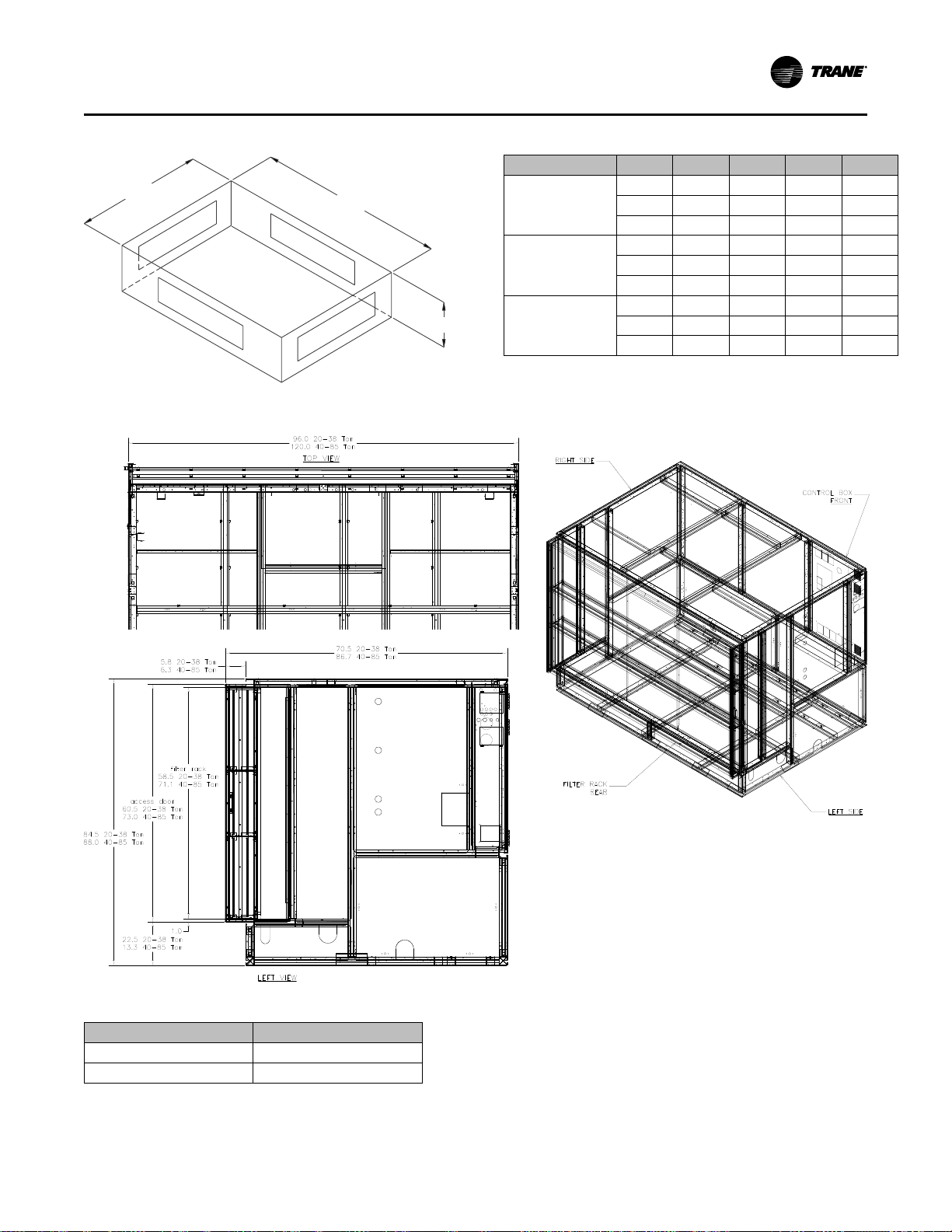
Figure 12. Six-inch filter rack
Table 15. Plenum dimensions (in)(lbs)
Unit Model A B C
64-7/8 24-5/8 95-7/8
64-7/8 32-3/8 95-7/8
64-7/8
80-3/8 21-1/8 119-7/8
80-3/8 28-5/8 119-7/8
80-3/8
80-1/2 19-5/8
80-1/2 27-3/4
80-1/2 43-1/2
45
45
20-38 Ton
42-80 Ton
90-110 Ton
low
std.
ext.
low
std.
ext.
low
std.
ext.
Filters
95-7/8
119-7/8
140 430
140 595
140 795
Weight
325
430
705
390
540
705
Table 16. Six-inch filter rack weight, lbs.
SCXF-SVX01Q-EN
Unit Size
20-38 212
42-80 257
Weight
29
Page 30
DDiimmeennssiioonnaall DDaattaa
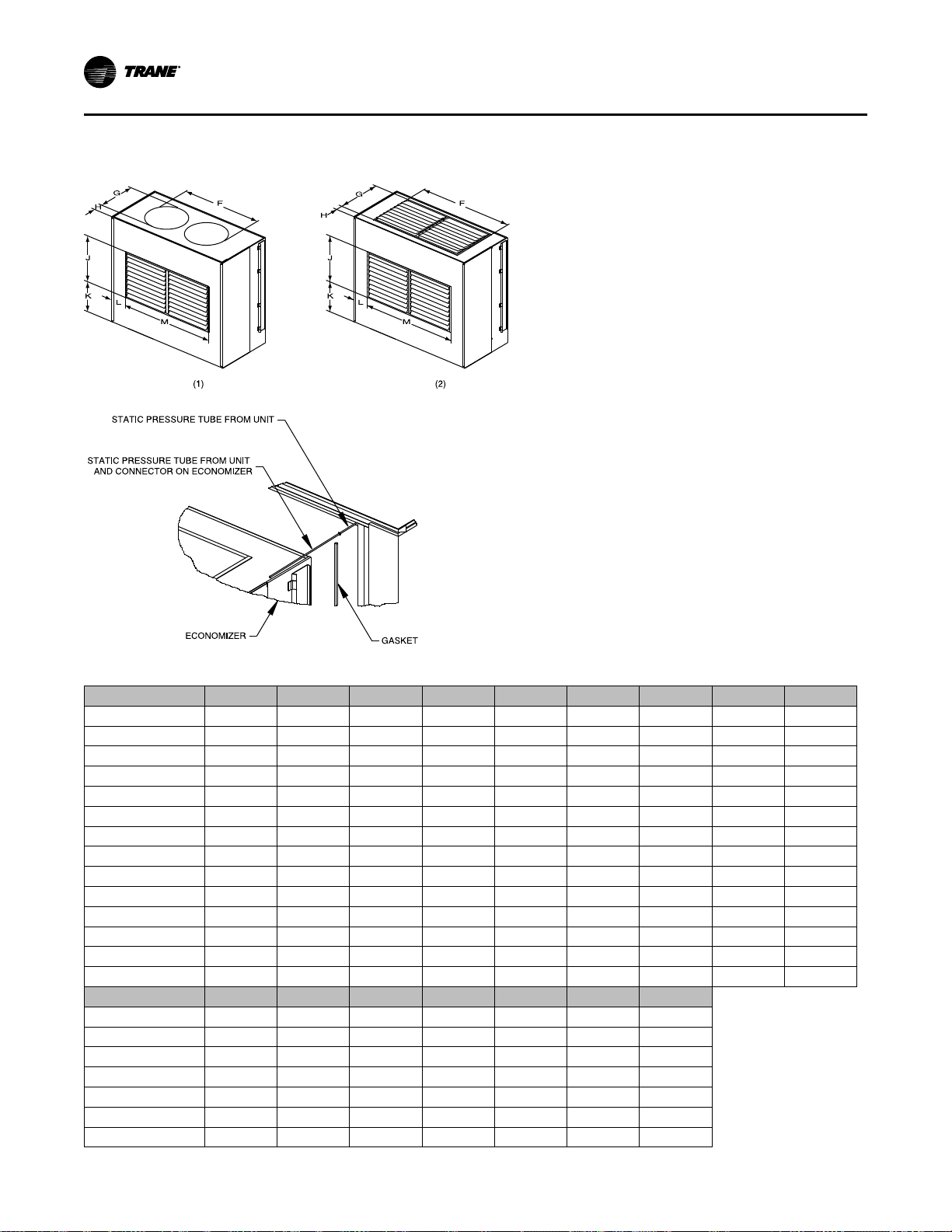
Airside Economizer
Figure 13. Airside economizer
Table 17. Airside economizer sizes and dimensions (in.)
Size A B C D E
SXWF 20 44 74
SXRF 25 44 74
SXWF 22 44 74
SXRF 29 44 74
SXWF 32 44 74
SXRF 30-35 44 74
SXWF 35-38 44 74
SXWF 42
SXRF 40
SXWF 46
SXRF 50
SXRF 60
SXRF 52-58
SXWF 65-80
Size
SXWF 20
SXRF 25
SXWF 22
SXRF 29
SXWF 32
SXRF 30-35
SXWF 35-38
57-3/8 86-1/2 13-1/4 104-3/8 8-7/8 83-5/8 63-1/2
57-3/8 86-1/2 13-1/4 104-3/8 8-7/8 94-1/8 63-1/2 28-1/8
57-3/8 86-1/2 13-1/4 104-3/8 8-7/8 94-1/8 63-1/2 28-1/8
57-3/8 86-1/2 13-1/4 104-3/8 8-7/8 96-5/8 63-1/2
57-3/8 86-1/2 13-1/4 104-3/8 8-7/8 96-5/8 63-1/2
57-3/8 86-1/2 13-1/4 104-3/8 8-7/8 96-5/8 63-1/2
57-3/8 86-1/2 13-1/4 104-3/8 8-7/8 96-5/8 63-1/2
H (1) H (2)
9-3/4 11-1/8 20-1/2 22-1/4
7-1/4 11-1/8 20-1/2 22-1/4
7-1/4 11-1/8 20-1/2 22-1/4
9-3/4 11-1/8 20-1/2 22-1/4 9-1/2 62-3/4
9-3/4 11-1/8 20-1/2 22-1/4 9-1/2 62-3/4
4-7/8 11-1/8 20-1/2 22-1/4 9-1/2 62-3/4
4-7/8 11-1/8 20-1/2 22-1/4 9-1/2 62-3/4
22-3/8 81-3/4 8-3/4 66-3/4 49-3/4 23-1/4 20-1/2
22-3/8 81-3/4 8-3/4 68-5/8 49-3/4 28-1/8 20-1/2
22-3/8 81-3/4 8-3/4 68-5/8 49-3/4 28-1/8 20-1/2
22-3/8 81-3/4 8-3/4 74-1/4 62-3/4 23-1/4 20-1/2
22-3/8 81-3/4 8-3/4 74-1/4 62-3/4 23-1/4 20-1/2
22-3/8 81-3/4 8-3/4 73-1/2 62-3/4
22-3/8 81-3/4 8-3/4 73-1/2 62-3/4
J K L M
16
16
16
F (1) F (2) G (1) G (2)
33
33
33 26
52
52
52
52
20-1/2
20-1/2
26
26
37-1/2
37-1/2
37-1/2
37-1/2
Weight
49-3/4
49-3/4
49-3/4
430
500
500
500
500
500
500
30
SCXF-SVX01Q-EN
Page 31

Table 17. Airside economizer sizes and dimensions (in.) (continued)
Air Inlet
See Table
42” (1066.8mm) (20-38 Ton)
Minimum
48” (1219mm) (42-110 Ton)
Control
Panel
36” (914.4mm)
Minimum
Left side
Front
Right side
Size
SXWF 42
SXRF 40
SXWF 46
SXRF 50
SXRF 60
SXRF 52-58
SXWF 65-80
H (1) H (2)
2-1/2
6-7/8
6-7/8
1-7/8 9-1/4 37-1/2
1-7/8 9-1/4 37-1/2
1-7/8 9-1/4 37-1/2
1-7/8 9-1/4 37-1/2
15 26
15 26
15 26
J K L M
24-3/4 20-3/8 63-1/2
24-3/4 20-3/8 63-1/2
24-3/4 20-3/8 63-1/2
19
19
19
19
20-3/8 63-1/2
20-3/8 63-1/2
20-3/8 63-1/2
20-3/8 63-1/2
DDiimmeennssiioonnaall DDaattaa
Weight
640
640
640
700
700
700
800
Service Clearances
See figure and table below for recommended service
and code clearances.
Table 18. Service and code clearance requirements
Side
Front
Left
Right
Inlet
Distance—inches (mm) Purpose
42 (1066) (20 to 38 tons) NEC code requirements
48 (1219) (42 to 110 tons)
36 (914) Filter, refrigeration, and waterside components
9 (229) Non VFD w/open return
18 (457)
9 (229) 20 to 80 tons, w/VFD 7.5 to 50 hp
36 (914) 90 to 110 tons (motor, condensers, and refrigeration)
18 (457) (20 to 80 tons)
36 (914) (90 to 110 tons)
Figure 14. Top view of self-contained unit showing
recommended service and code clearances(a)
NNoottee:: (a) See for right side clearance values for various
unit configurations.
Fan service/removal
Non VFD w/ducted return
Provides uniform airflow
Provides uniform airflow
SCXF-SVX01Q-EN
31
Page 32

Weights
Table 19. Unit weights — SCWF/SCRF/SIWF/SIRF
Airside
Economizer
lbs. (kg)
N/A N/A
N/A N/A
N/A N/A
20
22
25
29
32
35
38
42
46
52
58
65
72
80
90
100
110
25
29
30
35
40
50
60
Base Weight
lbs. (kg)
3102 (1407) 430 (195) 140 (64) 340 (154) 460 (209)
3102 (1407) 430 (195) 140 (64) 340 (154) 460 (209)
3170 (1438) 430 (195) 140 (64) 340 (154) 460 (209) 144 (65) 212 (96)
3326 (1508) 500 (227) 190 (86) 390 (177) 460 (209)
3514 (1594) 500 (227) 190 (86) 390 (177) 460 (209) 132 (60) 212 (96)
3721 (1688) 500 (227) 280 (127) 505 (229) 460 (209)
3819 (1732) 500 (227) 280 (127) 505 (229) 460 (209) 138 (63) 212 (96)
4615 (2093) 640 (290) 255 (116) 505 (229) 600 (272)
4705 (2134) 640 (290) 255 (116) 505 (229) 600 (272) 170 (77) 257 (117)
4892 (2219) 700 (318) 335 (152) 665 (302) 600 (272)
5142 (2332) 700 (318) 335 (152) 665 (302) 600 (272) 216 (98) 257 (117)
5371 (2436) 800 (363) 335 (152) 665 (302) 600 (272)
5491 (2490) 800 (363) 335 (152) 665 (302) 600 (272) 216 (98) 257 (117)
5814 (2637) 800 (363) 335 (152) 665 (302) 600 (272)
6330 (2871)
6840 (3103)
6852 (3108)
3231 (1465) 500 (227)
3231 (1465) 500 (227)
3321 (1506) 500 (227)
3421 (1552) 500 (227)
4294 (1948) 640 (290)
4731 (2146) 700 (318)
5288 (2399) 800 (363)
Unit
SCWF/
SIWF
SCRF/
SIRF
Notes:
1. All unit weights include refrigerant, water, and controllers, electric heat and valves.
2. Add 150 lbs. to total weight to obtain approximate shipping weight.
3. Flexible horizontal discharge plenum option weights: 45-inch plenum = 705 lbs., Standard height plenum = 430 lbs., Low height plenum = 325 lbs.
Unit
Size
2-Row
Waterside
Economizer
lbs. (kg)
N/A N/A
N/A N/A
N/A N/A
N/A N/A
N/A N/A
N/A N/A
N/A N/A
4-Row
Waterside
Economizer
lbs. (kg)
1015 (460)
1015 (460)
1015 (460)
Heating
Coil Box
lbs. (kg)
N/A
N/A
N/A
460 (209)
460 (209)
460 (209)
460 (209)
600 (272)
600 (272)
600 (272)
6-Row
Evap. Coil
lbs. (kg)
N/A
N/A
N/A
N/A
N/A
N/A
N/A
N/A
255 (116)
255 (116)
255 (116)
N/A N/A
N/A N/A
N/A N/A
N/A N/A
N/A N/A
N/A N/A
N/A N/A
6-inch filter
rack lbs.
(kg)
212 (96)
212 (96)
212 (96)
212 (96)
257 (117)
257 (117)
257 (117)
257 (117)
N/A
N/A
N/A
Table 20. Unit weights — CCRC/CIRC
Unit Size
CCRC/CIRC 20
CCRC/CIRC 29
CCRC/CIRC 32
32
Shipping Weight lbs (kg). Operating Weight lbs.(kg)
2030 (920) 1906 (865)
2084 (945) 1960 (890)
2138 (970) 2014 (915)
SCXF-SVX01Q-EN
Page 33

Table 20. Unit weights — CCRC/CIRC (continued)
WWeeiigghhttss
Unit Size
CCRC/CIRC 35
CCRC/CIRC 40
CCRC/CIRC 50
CCRC/CIRC 60
Shipping Weight lbs (kg). Operating Weight lbs.(kg)
3018 (1370) 2833 (1285)
3072 (1395) 2887 (1310)
3995 (1810) 3695 (1675)
4275 (1940) 3975 (1805)
Table 21. VFD weights
Without Bypass With Bypass
HP
7.5 126 57.153 114 51.710 114 51.710 7.5 215 97.522 170 77.111 170 77.111
LBS
10 126 57.153 114 51.710 126 57.153 10 215 97.522 215 97.522 215 97.522
15 152 68.946 126 57.153 126 57.153 15 220 99.790 215 97.522 215 97.522
20 152 68.946 126 57.153 126 57.153 20 220 99.790 215 97.522 215 97.522
25 152 68.946 126 57.153 126 57.153 25 250 113.398 215 97.522 215 97.522
30 177 80.286 152 68.946 152 68.946 30 250 113.398 220 99.790 220 99.790
40 177 80.286 152 68.946 152 68.946 40 290 131.542 220 99.790 220 99.790
50 NA NA 152 68.946 152 68.946 50 NA NA 250 113.398 250 113.398
60 NA NA 177 80.286 NA NA 60 NA NA 250 113.398 NA NA
Note: Weights include swing-out door.
Kg
LBS
Kg
LBS
Kg
HP
200V 460V 575V
200V 460V 575V
LBS
Kg
LBS
Kg
LBS
Kg
SCXF-SVX01Q-EN
33
Page 34

Installation - Mechanical
Unit Handling
WWAARRNNIINNGG
IImmpprrooppeerr UUnniitt LLiifftt!!
FFaaiilluurree ttoo pprrooppeerrllyy lliifftt uunniitt iinn aa LLEEVVEELL ppoossiittiioonn
ccoouulldd rreessuulltt iinn uunniitt ddrrooppppiinngg aanndd ppoossssiibbllyy
ccrruusshhiinngg ooppeerraattoorr//tteecchhnniicciiaann wwhhiicchh ccoouulldd rreessuulltt iinn
ddeeaatthh oorr sseerriioouuss iinnjjuurryy,, aanndd eeqquuiippmmeenntt oorr
pprrooppeerrttyy--oonnllyy ddaammaaggee..
TTeesstt lliifftt uunniitt aapppprrooxxiimmaatteellyy 2244 iinncchheess ((6611 ccmm)) ttoo
vveerriiffyy pprrooppeerr cceenntteerr ooff ggrraavviittyy lliifftt ppooiinntt.. TToo aavvooiidd
ddrrooppppiinngg ooff uunniitt,, rreeppoossiittiioonn lliiffttiinngg ppooiinntt iiff uunniitt iiss
nnoott lleevveell..
• Use spreader bars to avoid unit damage.
• Spreader bar must be a minimum of 11 feet for 2085 ton units and 12 feet for 90-110 tons. Chains
must not bear on top of unit.
• Do not use hooks to lift unit. Do not hook into open
channels to lift unit. Loop chain through lifting lug.
See detail in Figure 15, p. 34 and Figure 17, p. 35.
• Lift using overhead crane only. Adjust rigging for
unit center of gravity.
• Unit center of gravity will fall within center of
gravity block at various locations depending on unit
options.
• See unit nameplate for unit weights.
• Do not stack units.
Figure 15. Detail of how to loop chain through lifting
lug on self-contained
Table 22. Gravity Block Dimensions 20 to 80 tons, in.
Unit Size A B C
20-35 25 32 38
42-80 33 34 50
Figure 16. Gravity Block Dimensions 20 to 80 tons, in.
34
SCXF-SVX01Q-EN
Page 35

Figure 17. Gravity block location and dimensions for 90 to 110 ton units
IInnssttaallllaattiioonn -- MMeecchhaanniiccaall
Installation Preparation
Before installing the unit, perform the following
procedures to ensure proper unit operation.
1. Position the unit and skid assembly in its final
location.
2. Test lift the unit to determine exact unit balance and
stability before hoisting it to the installation
location. See “Unit Handling,” p. 34 for proper
rigging procedures and cautions.
3. Remove the skids from under the unit. See Figure
3, p. 22. Refer to the “Skid Removal” section. If you
find internal damage, file a claim immediately to
the delivering carrier.
4. Remove the protective shipping covers from the
unit.
5. Verify isolators are properly tightened for
operation. See “Unit Vibration Isolator Option,” p.
35.
6. Tighten compressor isolator mounting bolts.
Torque to 18 ft/lbs. (plus/minus 2 ft/Lbs.)
Unit Vibration Isolator Option
IImmppoorrttaanntt:: Vibration isolation is not necessary for the
unit since the factory internally isolates the
fan and compressors, thus creating double
isolation. Trane strongly recommends that
you consult a vibration specialist when
considering double isolation. In general,
Trane does not recommend doubleisolation.
If job requirements dictate unit isolators, use a housedspring isolator with a locating pin. Factory-provided
unit isolators are type CP and indicate the spring
number on the outer housing. See . Set the spring-type
vibration isolators in position before completing
electrical, piping, or duct connections. The 20-38 ton
units require four isolators per unit, and the 40-80 ton
units require six isolators per unit. Reference the
isolator placement sheet that ships with the isolators to
indicate proper placement.
Unit Isolator Installation Procedure
Use the following procedure to install isolators:
1. Position the isolators under the unit base referring
to the isolator placement sheet that ships with the
unit isolators. Lift one end of the unit at a time to
position the isolators. Fasten the isolators to the
floor using anchor bolts.
2. Level the unit by adjusting the isolator heights. Unit
weight may cause the upper housing of the spring
isolators to rest on the lower housing. Maintain
clearances between 1/4 and 1/2". To increase the
clearance, lift the unit off the isolator and turn the
leveling bolt counterclockwise. Verify that the unit
is level and the housing clearances are correct. The
maximum allowable difference between isolator
heights is 1/4". Shim as required under the
isolators.
NNoottee:: The unit is equipped with a positively sloped
drain pan to help indoor air quality (IAQ) and
does not require one corner of the unit to be
pitched.
SCXF-SVX01Q-EN
35
Page 36

3 Fan
Diameters
Duct
Discharge
3-inch
Duct
Flexible
Air
Return
IInnssttaallllaattiioonn -- MMeecchhaanniiccaall
Figure 18. Optional spring isolator dimensional data
Duct Connections
Return air enters the rear of the unit and conditioned
supply air discharges through the top. Attach supply air
ductwork directly to the unit’s top panel, around the fan
discharge opening. A duct collar is not provided.
NNoottee:: Units equipped with flexible horizontal discharge
plenum option may include a duct collar when
holes are factory cut. If discharge openings are
field-cut, refer to the following “Installation —
Plenum” section.
Install all air ducts according to the National Fire
Protection Association standards for the “Installation of
Air Conditioning and Ventilation Systems other than
Residence Type (NFPA 90A) and Residence Type Warm
Air Heating and Air Conditioning Systems (NFPA 90B).
Make duct connections to the unit with a flexible
material such as heavy canvas. If a fire hazard exists,
Trane recommends using Flexweave 1000, type FW30
or equivalent canvas. Use three inches for return duct
and three inches for discharge duct. Keep material
loose to absorb fan vibration.
• If using return ductwork to the unit, secure it with
three inches of flexible duct connector.
• Extend discharge duct upward without change in
size or direction for at least three fan diameters.
• Use 3" flexible duct connection on discharge
ductwork.
NNoottee:: Compressors and fan assembly are internally
isolated. External isolation devices (spring
mounting isolators) are at discretion of a
vibration specialist consulted by building or
HVAC system designer.
Run the ductwork straight from the opening for a
minimum of three fan diameters. See Figure 19, p. 36.
Extend remaining ductwork as far as possible without
changing size or direction. Do not make abrupt turns or
transitions near the unit due to increased noise and
excessive static losses. Use elbows with splitters or
turning vanes to minimize static losses.
Poorly constructed turning vanes may cause airflow
generated noise. Align the fan outlet properly with the
ductwork to decrease noise levels in the duct and to
increase fan performance. To complete trunk ductwork
to the VAV terminal units, refer to the VAV box
manuals for specific requirements. Check total external
static pressures against fan characteristics to be sure
the required airflow is available throughout the
ductwork.
To achieve maximum acoustical performance,
minimize the duct static pressure setpoint.
Figure 19. Duct connection recommendations
Installing the Plenum
Before installing plenum, attach insulation strip that
ships with plenum. See Figure 20, p. 37 for proper
36
SCXF-SVX01Q-EN
Page 37

Plenum Bottom View
Dashed line indicates correct insulation placement.
IInnssttaallllaattiioonn -- MMeecchhaanniiccaall
insulation location. Align plenum front with control
panel side of unit. Using strips and screws provided,
secure plenum to unit. Treat field-cut holes to prevent
fiberglass from entering the air stream.
NNoottee:: Plenum insulation must be applied properly to
prevent air bypass around the plenum. See
Figure 20, p. 37.
Figure 20. Correct plenum insulation placement
Installing the Airside Economizer
NNoottee:: Airside economizer option available on 20 to 80
tons only.
UUnniitt HHaannddlliinngg
1. Hoist the damper cabinet to the installation location
with straps positioned under the skid as shown in
Figure 21, p. 38. Use spreader bars to prevent unit
damage during lifting.
2. With the damper cabinet at its final location (near
the unit), remove the screws securing it to the skid
from the side flanges. Retain these screws for later
use.
UUnniitt PPrreeppaarraattiioonn
3. Open the access door and remove the damper
cabinet’s support legs and its hanging bracket. The
support legs are secured to the skid, and the
hanging bracket is secured with wire ties to an
inside flange near the cabinet’s base. Remove the
C-channel collar and install it on the unit, if not
already installed.
4. Remove the roll of 1/8" thick gasket from the
damper cabinet’s W-supports, and apply it to the Cchannel collar mounted on the rear of the unit. This
gasket will provide a seal between the damper
cabinet and the unit.
5. Attach the legs (with screws provided) to the leg
brackets located on the damper’s base.
6. Attach a field-provided clevis of suitable strength ( >
1/2"), to each of the corner lifting brackets through
the 7/8" diameter holes.
7. Attach to the clevises a means of lifting the damper
cabinet from its skid.
UUnniitt IInnssttaallllaattiioonn
8. Slowly raise the damper cabinet from its skid.
9. Attach the hanging bracket across the front of the
damper cabinet. Position it with its short flange
pointing to four o’clock, and secure it with screws
provided. See Figure 21, p. 38.
10. Lift the damper cabinet and position it such that the
hanging bracket is positioned over the unit’s Cchannel collar.
11. Lower the damper cabinet until the holes in its side
flanges are aligned with the holes in the C-channel
collar. Install screws removed in step 3 through the
damper cabinet’s side flanges and into the Cchannel’s corresponding holes.
12. Attach ductwork to the top and back dampers
according to local codes.
FFiieelldd WWiirriinngg CCoonnnneeccttiioonnss
WWAARRNNIINNGG
PPrrooppeerr FFiieelldd WWiirriinngg aanndd GGrroouunnddiinngg
RReeqquuiirreedd!!
FFaaiilluurree ttoo ffoollllooww ccooddee ccoouulldd rreessuulltt iinn ddeeaatthh oorr
sseerriioouuss iinnjjuurryy..
AAllll ffiieelldd wwiirriinngg MMUUSSTT bbee ppeerrffoorrmmeedd bbyy qquuaalliiffiieedd
ppeerrssoonnnneell.. IImmpprrooppeerrllyy iinnssttaalllleedd aanndd ggrroouunnddeedd
ffiieelldd wwiirriinngg ppoosseess FFIIRREE aanndd EELLEECCTTRROOCCUUTTIIOONN
hhaazzaarrddss.. TToo aavvooiidd tthheessee hhaazzaarrddss,, yyoouu MMUUSSTT ffoollllooww
rreeqquuiirreemmeennttss ffoorr ffiieelldd wwiirriinngg iinnssttaallllaattiioonn aanndd
ggrroouunnddiinngg aass ddeessccrriibbeedd iinn NNEECC aanndd yyoouurr llooccaall//
ssttaattee//nnaattiioonnaall eelleeccttrriiccaall ccooddeess..
13. Open the damper cabinet’s door and connect the
ffaaccttoorryy--pprroovviiddeedd pplluugg from the actuator to the
ffaaccttoorryy--pprroovviiddeedd pplluugg in the unit’s filter section.
14. CCaabbiinneettss wwiitthh TTRRAAQQ ddaammppeerrss oonnllyy:: Unroll two
rolls of pneumatic tubing located inside damper
cabinet. Route tubes through cabinet’s front upper
panel (0.25 dia. holes provided). Connect to two
pneumatic tubes protruding from customer
electrical connection panel on unit. Be sure to
connect black to black, white stripe to white stripe).
15. CCaabbiinneettss wwiitthh TTRRAAQQ ddaammppeerrss oonnllyy:: Locate the
“bullet” sensor and rolled up wiring in the unit’s
filter section. Route it into the damper cabinet and
insert the sensor into the sensor mounting clip
attached to underside of one of the Traq dampers.
SCXF-SVX01Q-EN
37
Page 38

Spreader
Bar
Strap
Lifting
Cable with
spreader bar
C-Channel
Hanging Bracket
IInnssttaallllaattiioonn -- MMeecchhaanniiccaall
Figure 21. Proper lifting of the airside economizer
(top) and airside economizer option (bottom)
NNoottee:: Four (4) condenser waterline drain plugs ship in
a bag in the left end of the unit. The installer
must field install these four plugs using pipe
thread sealer. An additional plug is provided for
units with a waterside economizer.
1. Install the vent plugs in the economizer coil headers
and condenser manifolds. See These plugs ship in a
bag with the condenser drain plugs.
2. Attach the water supply line to the inlet connection,
and the return line to the outlet connection.
Entering and leaving water connections for all
condensers are factory manifolded and require only
single connections for entering and leaving water. If
the unit has a waterside economizer and/or control
valves, the factory pipes between these
components.
3. If using a cooling tower, refer to for a typical piping
circuit from the unit.
4. Ensure the water pressure to the unit does not
exceed 400 psig.
NNoottee:: To prevent water pump damage, design system
piping to provide relief when using energy
saving waterside economizer valves.
Figure 22. Economizer coil vent and condenser
cleanout/drain plugs.
Water Piping
Condenser Connections
WWAARRNNIINNGG
HHiigghh PPrreessssuurree WWaatteerr!!
FFaaiilluurree ttoo ffoollllooww iinnssttrruuccttiioonnss bbeellooww ccoouulldd rreessuulltt iinn
ddeeaatthh oorr sseerriioouuss iinnjjuurryy,, aanndd eeqquuiippmmeenntt ddaammaaggee..
PPrroovviiddee rreelliieeff vvaallvvee oonn ssyysstteemm wwaatteerr ppiippiinngg ttoo
pprreevveenntt iinnssttaannttaanneeoouuss rreelleeaassee ooff hhiigghh pprreessssuurree
wwaatteerr..
NNOOTTIICCEE
PPrrooppeerr WWaatteerr TTrreeaattmmeenntt RReeqquuiirreedd!!
TThhee uussee ooff uunnttrreeaatteedd oorr iimmpprrooppeerrllyy ttrreeaatteedd wwaatteerr
ccoouulldd rreessuulltt iinn ssccaalliinngg,, eerroossiioonn,, ccoorrrroossiioonn,, aallggaaee oorr
sslliimmee..
UUssee tthhee sseerrvviicceess ooff aa qquuaalliiffiieedd wwaatteerr ttrreeaattmmeenntt
ssppeecciiaalliisstt ttoo ddeetteerrmmiinnee wwhhaatt wwaatteerr ttrreeaattmmeenntt,, iiff
aannyy,, iiss rreeqquuiirreedd.. TTrraannee aassssuummeess nnoo rreessppoonnssiibbiilliittyy
ffoorr eeqquuiippmmeenntt ffaaiilluurreess wwhhiicchh rreessuulltt ffrroomm uunnttrreeaatteedd
oorr iimmpprrooppeerrllyy ttrreeaatteedd wwaatteerr,, oorr ssaalliinnee oorr bbrraacckkiisshh
wwaatteerr..
Condenser water piping knockouts are in the lower left
end panel. If necessary, remove insulation to gain
access. All field-installed piping must conform to
applicable local, state, and federal codes. To complete
condenser water connections follow the procedure
below.
Condensate Drain Connections
The condensate drain is internally trapped. Condensate
drain connections are on the right side of the unit.
Connect condensate drain piping to the 1-1/4” NPT
female fitting, using at least 7/8" OD copper or 3/4" OD
iron pipe. Pitch the condensate line downward a
38
SCXF-SVX01Q-EN
Page 39

IInnssttaallllaattiioonn -- MMeecchhaanniiccaall
minimum of 1/2" for each 10' of horizontal run, away
from the unit. Be sure to install the condensate drain
“P” trap drain plug. Before starting the unit, fill the trap
with water to prevent negative pressure in the fan
section from impeding condensate flow.To facilitate
drain pipe cleaning, install plugged tees in place of 90°
elbows.
General Waterside Recommendations for Cooling Towers
Cooling tower control affects the unit cycle rates.
Condenser water temperature swings from 10-15°F
may cause excessive compressor, water valve, and unit
cycling. Be sure to set the tower controls to minimize
compressor/unit cycling.
Waterside Piping Arrangements
Install a condenser water pump between the cooling
tower (either open or closed) and the self-contained
unit. Lay out the remainder of the system condenser
piping in reverse returns. This helps balance the
system by equalizing the length of supply and return
pipes. Multi-story buildings may use a direct return
system with balancing valves at each floor.
Install the supply riser and its return in close proximity.
Furnish both with permanent thermometers to check
the waterside balance during startup and routine
maintenance checks.
Also, include strainers at each pump inlet and unit.
Install drain valves at the riser’s base to allow drainage
points for system flushing during startup and routine
maintenance. For condenser draining and header
removal, include a shutoff/balancing valve on the
entering and leaving waterside pipes, drain tees, and
unions of each unit.
NNoottee:: Unit does not have floor drains.
Figure 23. Condenser water piping components for
cooling tower system
(basic piping).This will cause the compressors to shut
down and the mechanical cooling function will lockout.
However, the economizer (if enabled) will continue to
function. The compressors will reset when the entering
water temperature reaches 58°F (15°C).
Units with variable water flow (intermediate piping)
have a modulating condensing pressure control valve
that allows compressor operation down to entering
water temperatures of 35°F (2°C).
For more information on constant and variable water
flow, see the Sequence of Operation section of this
manual.
NNoottee:: Units with a waterside economizer can be set
from the human interface panel for variable or
constant water flow.
Water Piping Verification
• Make return and supply water connections to the
unit and/or waterside economizer piping package
with recommended valves and piping components.
• Install unions to allow waterside maintenance.
• Install cooling tower and standby pumps.
• Treat water to prevent algae, slime, and corrosion.
• Prevent refrigerant piping from rubbing against
other objects.
Installating the Hydronic Coil
Steam and Hot Water Coil
WWAARRNNIINNGG
UUnniitt SSttrruuccttuurraall IInntteeggrriittyy!!
FFaaiilluurree ttoo ffoollllooww iinnssttrruuccttiioonnss bbeellooww ccoouulldd rreessuulltt iinn
ddeeaatthh oorr sseerriioouuss iinnjjuurryy..
UUnniitt ppaanneellss pprroovviiddee ssttrruuccttuurraall iinntteeggrriittyy.. DDoo nnoott
rreemmoovvee mmoorree tthhaann ttwwoo nnoonn--aaddjjaacceenntt ppaanneellss aatt oonnee
ttiimmee aass tthhiiss ccoouulldd ccaauussee tthhee pplleennuumm ffrraammee ttoo
ccoollllaappssee..
Water Temperature Requirements
Do not allow the entering water temperature to go
below 54°F (12.2°C) on units with constant water flow
SCXF-SVX01Q-EN
NNoottee:: Hydronic coil options are available only on 20-80
ton units and can be field or factory mounted.
1. Position the coil box behind the unit with open side
facing the unit inlet.
2. An envelope containing the gasket and mounting
screws to attach the coil to the unit ships in the
bottom of the unit. Install the pressure sensitive
gasket to the unit side of the vertical flange on the
coil box in two places.
3. Before attaching the coil box, connect the coil duct
static pressure tube. This must be done before the
coil box is bolted to the unit. If the unit connection
does not have a static pressure tube, then no
connection is required.
4. Apply edge protector to the flange on unit. Remove
knockout on the unit filter cover and install the
39
Page 40

IInnssttaallllaattiioonn -- MMeecchhaanniiccaall
bushing in the plastic bag. Run the wires through
the bushing and connect wires to the unit.
5. After connecting wires and the static pressure tube,
raise the coil box up against the unit and install the
mounting screws. Recommended lifting points are
at each end of the coil box.
6. Avoid routing wires over devices and sharp edges.
Use wire ties about every 12 inches to secure wires
to other wire harnesses.
7. Move the entering air temperature sensor upstream
of the coil to ensure proper operation.
Refrigerant System
Trane Water Cooled Commercial Self-Contained units
ship factory charged with R-410A refrigerant.
Trane Air Cooled Commercial Self-Contained and
Condenser units ship with a dry nitrogen holding
charge.
Before installing refrigerant piping, verify holding
charge is present. Momentarily depress the CSC
suction or discharge line (and condenser liquid line)
access port valves.
If charge is present, continue with piping installation.
If no nitrogen escapes the access valve, leak test the
unit refrigerant system to determine the leak source,
and repair. See Maintenance section, “Refrigerant Leak
Test Procedure,” p. 92. After finding leak, remove test
pressure and repair leak using proper brazing
procedures. See Maintenance section, “Brazing
Procedures,” p. 93. Retest unit(s) to ensure all leaks are
repaired. Continue with piping installation.
Interconnecting Piping
Refrigerant piping must be properly sized and applied.
These two factors have a significant effect on both
system performance and reliability.
Using , select proper liquid and discharge line size. Unit
connection sizes are also shown. Install
interconnecting piping using proper installation and
brazing procedures.
Work on only one circuit at a time to minimize system
exposure to potentially harmful moisture in the air.
Before installing piping verify compressor oil levels are
near top of sight glass or above.
NNoottee:: CSC units (and replacement compressors) ship
fully charged with POE oil from the factory.
Scroll compressors use POE oil (OIL00079, quart
container or OIL00080, gallon container), DO
NOT substitute.
Capped discharge and liquid line connections are
located near bottom, left side of the indoor unit. CCRC/
CIRC connections are located in the unit front, at top.
Remove caps with a tube cutter to minimize risk of
getting chips inside piping.
NNoottee:: When facing the control panel side of the unit.
Circuit #2 is always on the left and Circuit #1 is
always on the right.
Cleanliness is extremely important during system
installation to minimize residual contaminants, such as
oxidization and scale.
Attach vacuum pump and begin evacuation as soon as
piping installation is complete. This starts system
dehydration and helps prevent POE compressor oil
contamination. This will also indicate large leaks if
vacuum does not hold (below 400 microns and hold for
2 hours). Complete LeakTest and Evacuation (for
procedures, see “Refrigerant Leak Test Procedure,” p.
92 and “System Evacuation Procedures,” p. 93 in
Maintenance section) before starting “Preliminary
Refrigerant Charging,” p. 41.
NNootteess::
• Installation of a field supplied discharge line
access port near indoor units with optional
discharge line ball valve will make high side
pressure measurements easier during leak
test.
• UseType “L” refrigerant grade copper
tubing only.
NNOOTTIICCEE
CCoommpprreessssoorr DDaammaaggee!!
PPOOEE ooiill iiss hhyyggrroossccooppiicc –– iitt aabbssoorrbbss wwaatteerr ddiirreeccttllyy
ffrroomm tthhee aaiirr.. TThhiiss wwaatteerr iiss nneeaarrllyy iimmppoossssiibbllee ttoo
rreemmoovvee ffrroomm tthhee ccoommpprreessssoorr ooiill aanndd ccaann rreessuulltt iinn
ccoommpprreessssoorr ffaaiilluurreess..
TToo pprreevveenntt PPOOEE ooiill ffrroomm aabbssoorrbbiinngg wwaatteerr,, tthhee
ssyysstteemm sshhoouulldd nnoott rreemmaaiinn ooppeenn ffoorr lloonnggeerr tthhaann
nneecceessssaarryy.. WWhheenn ooppeenn,, ddrryy nniittrrooggeenn sshhoouulldd ffllooww
tthhrroouugghh tthhee ppiippiinngg.. OOnnllyy nneeww ooiill ccoonnttaaiinneerrss sshhoouulldd
bbee uusseedd ffoorr sseerrvviiccee aanndd mmaaiinntteennaannccee.. AAllwwaayyss uussee
tthhee ssmmaalllleesstt ccoonnttaaiinneerr ssiizzee rreeqquuiirreedd ffoorr tthhee jjoobb
rreeqquuiirreemmeennttss.. AAllwwaayyss lleeaavvee tthhee ooiill ccoonnttaaiinneerr
ttiigghhttllyy sseeaalleedd uunnttiill ttiimmee ooff uussee.. DDoo nnoott rreeuussee ooiill
tthhaatt hhaass bbeeeenn ooppeenneedd..
40
SCXF-SVX01Q-EN
Page 41

IInnssttaallllaattiioonn -- MMeecchhaanniiccaall
Table 23. Refrigerant piping sizes
Air Cooled Signature Connection Size (in)
Circuit 1 Circuit 2
SXRF Size
25, 29
30, 35, 40, 50
60
CXRC Size Liquid Discharge Liquid Discharge
20, 29
35, 40, 50
60
SXRF/CXRC Size Liquid Discharge Liquid Discharge
25/29 5/8 1 1/8 5/8 7/8
29/29 5/8 1 1/8 5/8 7/8
30/35 7/8 1 1/8 5/8 7/8
35/35 7/8 1 1/8 5/8 7/8
40/40 7/8 1 3/8
50/50 7/8 1 3/8 5/8 1 1/8
60/60 7/8 1 3/8 7/8 1 3/8
(a)
Use 1 1/8" for vertical risers.
Liquid Discharge Liquid Discharge
5/8 7/8 5/8 7/8
7/8 1 3/8 5/8 7/8
7/8 1 3/8 5/8 7/8
Remote Condenser Connection Size (in)
Circuit 1 Circuit 2
5/8 7/8 5/8 7/8
7/8 1 3/8 5/8 7/8
7/8 1 3/8 5/8 7/8
Interconnecting Tube Size (in)
Circuit 1 Circuit 2
(a)
5/8 7/8
Preliminary Refrigerant Charging
WWAARRNNIINNGG
CCoonnffiinneedd SSppaaccee HHaazzaarrddss!!
FFaaiilluurree ttoo ffoollllooww iinnssttrruuccttiioonnss bbeellooww ccoouulldd rreessuulltt iinn
ddeeaatthh oorr sseerriioouuss iinnjjuurryy..
DDoo nnoott wwoorrkk iinn ccoonnffiinneedd ssppaacceess wwhheerree rreeffrriiggeerraanntt
oorr ootthheerr hhaazzaarrddoouuss,, ttooxxiicc oorr ffllaammmmaabbllee ggaass mmaayy bbee
lleeaakkiinngg.. RReeffrriiggeerraanntt oorr ootthheerr ggaasseess ccoouulldd ddiissppllaaccee
aavvaaiillaabbllee ooxxyyggeenn ttoo bbrreeaatthhee,, ccaauussiinngg ppoossssiibbllee
aasspphhyyxxiiaattiioonn oorr ootthheerr sseerriioouuss hheeaalltthh rriisskkss.. SSoommee
ggaasseess mmaayy bbee ffllaammmmaabbllee aanndd oorr eexxpplloossiivvee.. IIff aa lleeaakk
iinn ssuucchh ssppaacceess iiss ddeetteecctteedd,, eevvaaccuuaattee tthhee aarreeaa
iimmmmeeddiiaatteellyy aanndd ccoonnttaacctt tthhee pprrooppeerr rreessccuuee oorr
rreessppoonnssee aauutthhoorriittyy..
SCXF-SVX01Q-EN
WWAARRNNIINNGG
EExxpplloossiioonn HHaazzaarrdd!!
FFaaiilluurree ttoo pprrooppeerrllyy rreegguullaattee pprreessssuurree ccoouulldd rreessuulltt
iinn aa vviioolleenntt eexxpplloossiioonn,, wwhhiicchh ccoouulldd rreessuulltt iinn ddeeaatthh,,
sseerriioouuss iinnjjuurryy,, oorr eeqquuiippmmeenntt oorr pprrooppeerrttyy--oonnllyy-ddaammaaggee..
WWhheenn uussiinngg ddrryy nniittrrooggeenn ccyylliinnddeerrss ffoorr
pprreessssuurriizziinngg uunniittss ffoorr lleeaakk tteessttiinngg,, aallwwaayyss pprroovviiddee
aa pprreessssuurree rreegguullaattoorr oonn tthhee ccyylliinnddeerr ttoo pprreevveenntt
eexxcceessssiivveellyy hhiigghh uunniitt pprreessssuurreess.. NNeevveerr pprreessssuurriizzee
uunniitt aabboovvee tthhee mmaaxxiimmuumm rreeccoommmmeennddeedd uunniitt tteesstt
pprreessssuurree aass ssppeecciiffiieedd iinn aapppplliiccaabbllee uunniitt lliitteerraattuurree..
41
Page 42

IInnssttaallllaattiioonn -- MMeecchhaanniiccaall
WWAARRNNIINNGG
HHaazzaarrddoouuss PPrreessssuurreess!!
FFaaiilluurree ttoo ffoollllooww iinnssttrruuccttiioonnss bbeellooww ccoouulldd rreessuulltt iinn
aa vviioolleenntt eexxpplloossiioonn,, wwhhiicchh ccoouulldd rreessuulltt iinn ddeeaatthh oorr
sseerriioouuss iinnjjuurryy..
IIff aa hheeaatt ssoouurrccee iiss rreeqquuiirreedd ttoo rraaiissee tthhee ttaannkk
pprreessssuurree dduurriinngg rreemmoovvaall ooff rreeffrriiggeerraanntt ffrroomm
ccyylliinnddeerrss,, uussee oonnllyy wwaarrmm wwaatteerr oorr hheeaatt bbllaannkkeettss ttoo
rraaiissee tthhee ttaannkk tteemmppeerraattuurree.. DDoo nnoott eexxcceeeedd aa
tteemmppeerraattuurree ooff 115500°°FF.. DDoo nnoott uunnddeerr aannyy
cciirrccuummssttaanncceess aappppllyy ddiirreecctt ffllaammee ttoo aannyy ppoorrttiioonn ooff
tthhee ccyylliinnddeerr..
CCAAUUTTIIOONN
RReeffrriiggeerraanntt aatt FFrreeeezziinngg TTeemmppeerraattuurree!!!!
DDiirreecctt ccoonnttaacctt wwiitthh lliiqquuiidd rreeffrriiggeerraanntt ccoouulldd rreessuulltt
iinn mmiinnoorr oorr mmooddeerraattee iinnjjuurryy..
AAvvooiidd ccoonnttaacctt wwiitthh sskkiinn.. IIff wwoorrkkiinngg wwiitthh rreeffrriiggeerraanntt
iiss nneecceessssaarryy,, yyoouu MMUUSSTT wweeaarr aallll PPeerrssoonnaall
PPrrootteeccttiivvee EEqquuiippmmeenntt ((PPPPEE)) iinncclluuddiinngg eeyyee
pprrootteeccttiioonn,, ssaaffeettyy gglloovveess,, lloonngg sslleeeevveess,, aanndd ppaannttss..
IInn ccaassee ooff ccoonnttaacctt,, ttrreeaatt tthhee iinnjjuurryy ssiimmiillaarr ttoo
ffrroossttbbiittee.. SSlloowwllyy wwaarrmm tthhee aaffffeecctteedd aarreeaa wwiitthh
lluukkeewwaarrmm wwaatteerr aanndd sseeeekk iimmmmeeddiiaattee mmeeddiiccaall
aatttteennttiioonn..
NNOOTTIICCEE
CCoommpprreessssoorr DDaammaaggee!!
FFaaiilluurree ttoo ffoollllooww iinnssttrruuccttiioonnss bbeellooww ccoouulldd rreessuulltt iinn
ccoommpprreessssoorr ffaaiilluurree..
IIff iitt bbeeccoommeess nneecceessssaarryy ttoo rreemmoovvee oorr rreecchhaarrggee tthhee
ssyysstteemm wwiitthh rreeffrriiggeerraanntt,, iitt iiss iimmppoorrttaanntt tthhaatt tthhee
ffoolllloowwiinngg aaccttiioonnss aarree ttaakkeenn::
•• TToo pprreevveenntt ccrroossss ccoonnttaammiinnaattiioonn ooff rreeffrriiggeerraannttss
aanndd ooiillss,, uussee oonnllyy ddeeddiiccaatteedd RR--441100AA sseerrvviiccee
eeqquuiippmmeenntt..
•• DDiissccoonnnneecctt uunniitt ppoowweerr bbeeffoorree eevvaaccuuaattiioonn aanndd
ddoo nnoott aappppllyy vvoollttaaggee ttoo ccoommpprreessssoorr wwhhiillee uunnddeerr
vvaaccuuuumm..
•• DDuuee ttoo pprreesseennccee ooff PPOOEE ooiill,, ddoo nnoott lleeaavvee tthhee
ssyysstteemm ooppeenn ffoorr mmoorree tthhaann 11 hhoouurr..
•• AAllllooww tthhee ccrraannkkccaassee hheeaatteerr ttoo ooppeerraattee aa
mmiinniimmuumm ooff 2244 hhoouurrss bbeeffoorree ssttaarrttiinngg
ccoommpprreessssoorrss..
•• DDoo nnoott aallllooww lliiqquuiidd rreeffrriiggeerraanntt ttoo eenntteerr tthhee
ssuuccttiioonn lliinnee..
•• DDoo nnoott aallllooww eexxcceessssiivvee lliiqquuiidd aaccccuummuullaattiioonn iinn
tthhee lliiqquuiidd lliinneess..
•• DDoo nnoott ooppeerraattee tthhee ccoommpprreessssoorrss wwiitthhoouutt tthhee
pprrooppeerr lleevveell ooff rreeffrriiggeerraanntt iinn eeaacchh cciirrccuuiitt..
To charge the system:
1. Verify system leak check (including interconnecting
piping for air cooled systems) and evacuation are
complete before adding refrigerant.
See “Refrigerant Leak Test Procedure,” p. 92 and
“System Evacuation Procedures,” p. 93
2. Ensure field-supplied unit disconnect is OFF. Verify
that the unit 115 volt control circuit switch is OFF
and reset relays have been unplugged, to prevent
inadvertent compressor starts.
3. Turn field-supplied unit disconnect ON to energize
crankcase heaters. Verify crankcase heaters are
operating.
4. Verify all service valves are open.
5. See CSC General Data for unit refrigerant charge.
6. See for additional charge required based on field
piping size and length. Add this to the charge
amount from Step 5 for the total charge.
NNoottee:: Step 6 not required for field piping under 25
feet, or for water cooled system.
7. At the liquid line angle valve add as much R-410A
LIQUID as possible up to, but not exceeding, total
charge amount. Depending on conditions, it may
not be possible to add more than 60% of the total
charge. This will be adequate for compressor
startup. More charge will be added after
compressors are started. Use an accurate scale to
measure and record preliminary amount of
refrigerant added to each circuit.
NNoottee:: AAiirr CCoooolleedd OOnnllyy:: Add charge at the
condenser access valve or field supplied
discharge line access valve. If angle valve is
used for charging, liquid line solenoid valve
should be open.
8. DO NOT add refrigerant in the suction line during
preliminary charging to minimize refrigerant in
system low side prior to compressor start.
9. Record charge amount added.
10. If total charge is not reached see Final Refrigerant
Charge in Startup.
11. Verify wiring has been returned to original.
NNoottee:: AAiirr CCoooolleedd OOnnllyy:: Verify liquid line solenoid
valve has been returned to original.
Table 24. Charge add —lbs per 10 ft of line
Piping Size (in) Liquid Line (lbs)
5/8
7/8
1 1/8
1 3/8
Note: Amounts listed are for 10 ft of pipe above 25'. Actual
requirements will be in direct proportion to the actual length
of piping.
1.07 -
2.23 0.31
- 0.53
- 0.80
Discharge Line
(lbs)
42
SCXF-SVX01Q-EN
Page 43

Installation - Electrical
Unit Wiring Diagrams
Specific unit wiring diagrams are provided on the
inside of the control panel door. Use these diagrams
for connections or trouble analysis.
Supply Power Wiring
It is the responsibility of the installer to provide power
supply wiring to the unit terminal block or the nonfused disconnect switch option. Wiring should conform
to NEC and all applicable code requirements.
Bring supply wiring through the knockout in the lower
left side of the unit control panel. Connect the three
phase wires to the power terminal block or the nonfused disconnect switch in the control box terminals.
Refer to specific wiring diagrams and fuse information
in the control panel.
WWAARRNNIINNGG
HHaazzaarrddoouuss SSeerrvviiccee PPrroocceedduurreess!!
FFaaiilluurree ttoo ffoollllooww aallll pprreeccaauuttiioonnss iinn tthhiiss mmaannuuaall aanndd
oonn tthhee ttaaggss,, ssttiicckkeerrss,, aanndd llaabbeellss ccoouulldd rreessuulltt iinn
ddeeaatthh oorr sseerriioouuss iinnjjuurryy..
TTeecchhnniicciiaannss,, iinn oorrddeerr ttoo pprrootteecctt tthheemmsseellvveess ffrroomm
ppootteennttiiaall eelleeccttrriiccaall,, mmeecchhaanniiccaall,, aanndd cchheemmiiccaall
hhaazzaarrddss,, MMUUSSTT ffoollllooww pprreeccaauuttiioonnss iinn tthhiiss mmaannuuaall
aanndd oonn tthhee ttaaggss,, ssttiicckkeerrss,, aanndd llaabbeellss,, aass wweellll aass tthhee
ffoolllloowwiinngg iinnssttrruuccttiioonnss:: UUnnlleessss ssppeecciiffiieedd ootthheerrwwiissee,,
ddiissccoonnnneecctt aallll eelleeccttrriiccaall ppoowweerr iinncclluuddiinngg rreemmoottee
ddiissccoonnnneecctt aanndd ddiisscchhaarrggee aallll eenneerrggyy ssttoorriinngg
ddeevviicceess ssuucchh aass ccaappaacciittoorrss bbeeffoorree sseerrvviicciinngg..
FFoollllooww pprrooppeerr lloocckkoouutt//ttaaggoouutt pprroocceedduurreess ttoo
eennssuurree tthhee ppoowweerr ccaann nnoott bbee iinnaaddvveerrtteennttllyy
eenneerrggiizzeedd.. WWhheenn nneecceessssaarryy ttoo wwoorrkk wwiitthh lliivvee
eelleeccttrriiccaall ccoommppoonneennttss,, hhaavvee aa qquuaalliiffiieedd lliicceennsseedd
eelleeccttrriicciiaann oorr ootthheerr iinnddiivviidduuaall wwhhoo hhaass bbeeeenn
ttrraaiinneedd iinn hhaannddlliinngg lliivvee eelleeccttrriiccaall ccoommppoonneennttss
ppeerrffoorrmm tthheessee ttaasskkss..
NNOOTTIICCEE
UUssee CCooppppeerr CCoonndduuccttoorrss OOnnllyy!!
FFaaiilluurree ttoo uussee ccooppppeerr ccoonndduuccttoorrss ccoouulldd rreessuulltt iinn
eeqquuiippmmeenntt ddaammaaggee aass tthhee eeqquuiippmmeenntt wwaass nnoott
ddeessiiggnneedd oorr qquuaalliiffiieedd ttoo aacccceepptt ootthheerr ttyyppeess ooff
ccoonndduuccttoorrss..
NNOOTTIICCEE
MMoottoorr DDaammaaggee!!
CCoorrrreecctt pphhaassee sseeqquueennccee iiss ccrriittiiccaall.. IIff pphhaassee
sseeqquueennccee ooff tthhee iinnccoommiinngg lliinnee vvoollttaaggee iiss nnoott
ccoorrrreecctt,, iitt ccoouulldd rreessuulltt iinn mmoottoorr ddaammaaggee..
Voltage Range
Voltages must be within ±10% the nameplate voltage.
Ensure the unit voltage is balanced by measuring at the
compressor terminals. Voltage imbalance on three
phase systems can cause motor overheating and
premature failure. Maximum allowable imbalance is
2.0%.
Voltage Imbalance
Read the voltage at the compressor terminals to
determine if it is balanced. Voltage imbalance on three
phase systems can cause motor overheating and
premature failure. The maximum allowable imbalance
is 2.0%. Voltage imbalance is defined as 100 times the
sum of the deviation of the three voltages from the
average (without regard to sign) divided by the average
voltage. For example, if the three measured voltages
are 221, 230, and 227, the average voltage would be:
(221 + 230 + 227) / 3 = 226 volts
The percentage of voltage imbalance is then:
100 * (226 — 221) / 226 = 2.2%
Phase Monitor
Unit is equipped with phase monitor in control box.
The phase monitor will protect against phase loss,
imbalance and reversal of line voltage. If a fault occurs,
the red LED will energize. While the fault condition is
present, the phase monitor interrupts the 115V control
circuit. If no faults are observed, a green LED will be
energized.
Control Power
NNOOTTIICCEE
CCoommppoonneenntt DDaammaaggee!!
FFaaiilluurree ttoo ffoollllooww iinnssttrruuccttiioonnss bbeellooww ccoouulldd rreessuulltt iinn
iimmmmeeddiiaattee oorr pprreemmaattuurree ccoommppoonneenntt ffaaiilluurreess..
UUnniitt ttrraannssffoorrmmeerrss aarree ssiizzeedd ttoo pprroovviiddee ppoowweerr ttoo
tthhee uunniitt oonnllyy.. DDoo nnoott uussee tthheessee ttrraannssffoorrmmeerrss ttoo
ssuuppppllyy ppoowweerr ttoo ffiieelldd eeqquuiippmmeenntt..
In this example, 2.2% imbalance is not acceptable.
Whenever a voltage imbalance of more than 2.0%
exists, check the voltage at the unit disconnect switch.
If the imbalance at the unit disconnect switch does not
exceed 2.0%, faulty unit wiring is causing the
imbalance. Conduct a thorough inspection of the unit
electrical wiring connections to locate the fault, and
make any repairs necessary.
Access the connection terminal block through the
control panel on the upper left side of the unit. All
wiring should conform to NEC and applicable local
code requirements.
Be sure all wiring connections are secure. Reference
the unit specific diagrams inside the control panel.
SCXF-SVX01Q-EN
43
Page 44

IInnssttaallllaattiioonn -- EElleeccttrriiccaall
NNoottee:: Unit transformers IT1, IT3, IT4 and IT5 are sized
to provide power to the unit only.
Determination of maximum fuse size (MFS) and
maximum circuit breaker size (MCB):
MFS and MCB = 2.25 x largest motor amps (FLA or
Selection Procedures
RLA = rated load amps
Compressor LRA = locked rotor amps
Fan motor LRA = locked rotor amps, N.E.C. Table 430 150
FLA = full load amps, N.E.C. Table 430 - 150
Voltage utilization range is ±10%
Determination of minimum circuit ampacity (MCA).
MCA = 1.25 x largest motor amps/VFD amps (FLA or
RLA) + the sum of the remaining motor amps.
RLA) + the sum of the remaining motor amps.
For units with the dual power option, there are two
electrical circuits that need calculations using the
previous formulas:
• Circuit #1— fans
• Circuit #2— compressors
If the rating value determined does not equal a
standard current rating of over current protective
device, use the next lower standard rating for the
marked maximum rating.
Table 25. Number of compressors per unit
SCRF/SIRF
SCWF/SIWF
10 HP 1 3 2 - 1 - - 2 -
15 HP 1 - 1 3 3 4 5 4 6
25 - 29 30 - 35 40 50 60
29 - 32 35 - 38 42 - 46 52 - 58 65 - 72 80 90 100 110
Table 26. Compressor Electrical Data
SCWF/SIWF SCRF/SIRF
200V 460V 575V 200V 460V 575V
HP RLA LRA RLA LRA RLA LRA HP RLA LRA RLA LRA RLA LRA
10 41.4 267 18.6 142 15.8 103 10 41.4 267 18.6 142 15.8 103
15 56.9 351 25.5 197 23.1 146 15 56.9 351 25.5 197 23.1 146
Table 27. Fan motor electrical data
HP TYPE
5
7.5
10
15
20
25
30
OPD 15.3 109.0 6.6 48.0 5.2 40.0
TEFC 15.2 128.8 6.7 56.0 5.3 44.8
OPD 23.3 199.0 9.7 84.8 7.8 61.4
TEFC 22.1 164.0 9.6 70.9 7.7 56.9
OPD 29.5 260.0 12.6 118.0 10.1 72.3
TEFC 29.5 216.0 12.8 103.0 10.3 83.9
OPD 43.4 271.0 18.9 118.0 15.1 95.9
TEFC 42.5 288.0 18.5 125.0 15.0 102.0
OPD 57.0 350.0 24.5 156.0 19.6 126.0
TEFC 55.5 402.0 24.2 175.0 19.4 140.0
OPD 70.0 432.0 30.5 190.0 24.5 155.0
TEFC 71.0 523.0 30.5 188.0 24.5 140.0
OPD 82.2 514.0 36.6 252.0 29.0 200.0
TEFC 81.0 560.0 38.0 274.0 29.2 177.0
FLA LRA FLA LRA FLA LRA
200V 460V 575V
44
SCXF-SVX01Q-EN
Page 45

Table 27. Fan motor electrical data (continued)
200V 460V 575V
HP TYPE
40
50
60 ODP
OPD 109.0 615.0 49.0 330.0 40.0 270.0
TEFC 111.0 758.0 47.4 320.0 38.0 280.0
ODP
TEFC
FLA LRA FLA LRA FLA LRA
N/A N/A
N/A N/A
N/A N/A
IInnssttaallllaattiioonn -- EElleeccttrriiccaall
59.0 378.0 47.0 305.0
59.0 455.0 47.2 380.0
71.0 464.0
N/A N/A
Table 28. VFD electrical data
VFD L.I.C.
Without Bypass With Bypass
200V 460V 575V 200V 460V 575V
HP
7.5 23.8 10.6 8.8 32.2 10.6 8.8
10 32.2 14 11.1 48.3 14 16.6
15 48.3 21 16.6 61.9 21 16.6
20 61.9 27.6 21.4 78.2 27.6 21.4
25 78.2 34 26.3 92 34 26.3
30 92 41 31.2 117 41 31.2
40 117 53 39.9 139.2 53 39.9
50 NA 64 50.6
60 NA 77 NA
Note: Values are at the maximum VFD input rating and not the
reduced motor values. L.I.C. = Line Input Current.
n/a
n/a
64 50.6
77
Table 29. Single stage electric heat electrical data
SXWF
Size
20 - 18 50 21.7
22 - 18 50 21.7
25 20 18 50 21.7
29 25 23 63.8 27.7
32 29 23 63.8 27.7
35 30 27 75 32.5
38 35 27 75 32.5
42 - 31.5 87.4 37.9
46 40 31.5 87.4 37.9
52 - 39 108.3 46.9
58 50 39 108.3 46.9
65 - 48 133.2 57.7
72 - 48 133.2 57.7
SXRF
Size Heat Kw
200V
Amps
460V
Amps
n/a
Table 29. Single stage electric heat electrical data
(continued)
SXWF
Size
80 60 48 133.2 57.7
Note: Electric heat amperage should not be considered when
determining minimum circuit ampacity. The current of the
unit in the heating mode will not exceed the current of the
unit in the cooling mode
SXRF
Size Heat Kw
200V
Amps
460V
Amps
Table 30. 2 stage electric heat electrical data
Unit Size
SCWF Heat kW
90 76
100 76
110 76
200V
Amps
N/A
N/A
N/A
460V
Amps
95.39
95.39
95.39
575V
Amps
N/A
N/A
N/A
Static Pressure Transducer Installation (VAV units only)
Supply air static pressure controls the inverter option.
A static pressure head assembly ships separate in
control panel for field installation in the supply air duct
work. Installer is responsible for providing pneumatic
tubing.
Transducer Location
Place head assembly in an area of ductwork that will
provide an average and evenly distributed airflow
pattern. Use the following guidelines to determine an
appropriate installation location.
1. Locate static head assembly approximately 2/3 to 3/
4 the way down longest duct run, in an area
approximately 10 duct diameters downstream and
2 duct diameters upstream of major interferences,
turns, or changes in duct diameter.
2. When installing pneumatic tubing between head
assembly and transducer in control panel, do not
exceed 250ft for 1/4” OD tubing or 500ft for 3/8” OD
tubing.
SCXF-SVX01Q-EN
45
Page 46

Duct
Pressure
Sensor
Static Pressure
Head Assembly
Connector
for 1/4”
Tubing
Sheet Metal Screws
(provided by installer)
NOTE:
Pleace sensor inlet
perpendicular to airflow.
IInnssttaallllaattiioonn -- EElleeccttrriiccaall
Installing the Transducer
Use the following procedure to properly install the
static pressure transducer:
1. Mount pressure sensing head assembly in duct
with sensing tip is in middle of the duct so that it
will provide a proper pressure measurement. See
Figure 24, p. 46.
2. Connect the pneumatic tubing from the sensing
head to the push-on tubing connection in the
control panel. Use a plastic static pickup tubing. Do
not exceed 250 feet for 1/4” OD tubing or 500 feet
for 3/8” OD tubing.
Transducer inside control panel picks up low side or
reference pressure.
NNoottee:: If plastic tubing pulls away from a connection,
trim it back before replacing it on the fitting.
Stretched tubing may leak and cause faulty
control.
Figure 24. Static pressure sensor installation
Zone Sensor Options for Control Units
Zone sensor options are available and can be ordered
with the unit or after the unit ships. They also can be
ordered through “Unitary Accessories (ACC)”/“UPG
Rooftop, Packaged Heat Pump, Split System
Accessories (ACC)”. Contact your local Trane sales
office. Following is a full description of zone sensors
and their functions. Following is a full description of
zone sensors and their functions. See Table 39, p. 70
for the zone sensor temperature vs. resistance
coefficient curve.
Standard with All Units: BAYSENS077
Zone temperature sensor only
This zone sensor module ships with all units, and can
be used with BAYSENS019, BAYSENS020, or
BAYSENS021 remote sensors. When this sensor is
wired to one of these remote zone sensors, wiring must
be 18 AWG shielded twisted pair (Belden 8760 or
equivalent). Refer to the specific zone sensor for wiring
details. It provides the following features and system
control functions:
• Remote temperature sensing in the zone
• Morning warm-up sensor
• Zone sensor for ICS™ systems
• Zone temperature averaging
When used as a remote sensor for standard zone
sensor, the thermistor sensor must be disabled.
(Possible Schematic Designation(s): 5U23, 5U26, 5U30,
and 5RT5.)
46
SCXF-SVX01Q-EN
Page 47

CV Unit Zone Sensor Options
BAYSENS108
Dual setpoint, manual/automatic changeover sensor
IInnssttaallllaattiioonn -- EElleeccttrriiccaall
BAYSENS110
Dual setpoint, manual/automatic changeover sensor with system
function
BAYSENS108 and BAYSENS110
These zone sensor modules are for use with cooling/
heating constant volume units. They have four system
switch settings (heat, cool, auto, and off) and two fan
settings (on and auto).The zone sensor provides either
manual or automatic changeover control with dual
setpoint capability.
BAYSENS108 and BAYSENS110 features and system
control functions include:
• System control switch to select heating mode
(HEAT), cooling mode (COOL), automatic selection
of heating or cooling as required (AUTO), or to turn
the system off (OFF).
• Fan control switch to select automatic fan operation
while actively heating or cooling (AUTO), or
continuous fan operation (ON).
• Dual temperature setpoint levers for setting desired
temperature. The blue lever controls cooling, and
the red lever controls heating.
• Thermometer to indicate temperature in the zone.
This indicator is factory calibrated.
(Possible Schematic Designation: 5U29)
BAYSENS110 only function status indicator lights
include:
• SYSTEM ON glows continuously during normal
operation, or blinks if system is in test mode.
• COOL glows continuously during cooling cycles, or
blinks to indicate a cooling system failure.
• HEAT glows continuously during heating cycles, or
blinks to indicate a heating system failure.
• SERVICE blinks or glows to indicate a problem.
These signals vary depending on the particular
equipment being used.
(Possible Schematic Designation: 5U29)
Integrated Comfort Systems Sensors for CV and VAV Applications
CV and VAV Unit Zone Sensor Options
These zone sensor options are for use with cooling/
heating Integrated Comfort System (ICS) systems.
BAYSENS074
Zone temperature sensor with timed override and local
setpoint adjustment
This electronic analog sensor features single setpoint
capability and timed override with override
cancellation. BAYSENS074 features and system control
functions include:
• Remote temperature sensing in the zone
• A timed override button to move an ICS or a
building management system from its
“unoccupied” to “occupied” mode
• Thumbwheel for local setpoint adjustment
• A cancel button to cancel the “unoccupied
override” command
(Possible Schematic Designation: 5U23)
SCXF-SVX01Q-EN
47
Page 48

RIGHT BACK
1-3/32 [27,43 mm]
3/32 [2,00 mm]
1-3/8 [35,00 mm]
19/32 [15,00 mm]
15/64 [6,00 mm]
3-5/32 [80,00 mm]
1-1/32 [26,16 mm]
5/32 [3,81 mm] 4X
IInnssttaallllaattiioonn -- EElleeccttrriiccaall
BAYSENS073
Zone temperature sensor with timed override
This electronic analog sensor features single setpoint
capability and timed override with override
cancellation. It is used with a Trane® Integrated
Comfort™ system.
BAYSENS073 features and system control functions
include:
• Remote temperature sensing in the zone
• A timed override button to move an ICS or a
building management system from its
“unoccupied” to “occupied” mode
• Cancel button to cancel the “unoccupied override”
mode
(Possible Schematic Designation: 5U23)
Figure 25. Zone sensor mounting hole locations for:
BAYSENS077
Zone Sensor Installation
WWAARRNNIINNGG
HHaazzaarrddoouuss VVoollttaaggee ww//CCaappaacciittoorrss!!
FFaaiilluurree ttoo ddiissccoonnnneecctt ppoowweerr aanndd ddiisscchhaarrggee
ccaappaacciittoorrss bbeeffoorree sseerrvviicciinngg ccoouulldd rreessuulltt iinn ddeeaatthh oorr
sseerriioouuss iinnjjuurryy..
DDiissccoonnnneecctt aallll eelleeccttrriicc ppoowweerr,, iinncclluuddiinngg rreemmoottee
ddiissccoonnnneeccttss aanndd ddiisscchhaarrggee aallll mmoottoorr ssttaarrtt//rruunn
ccaappaacciittoorrss bbeeffoorree sseerrvviicciinngg.. FFoollllooww pprrooppeerr
lloocckkoouutt//ttaaggoouutt pprroocceedduurreess ttoo eennssuurree tthhee ppoowweerr
ccaannnnoott bbee iinnaaddvveerrtteennttllyy eenneerrggiizzeedd.. FFoorr vvaarriiaabbllee
ffrreeqquueennccyy ddrriivveess oorr ootthheerr eenneerrggyy ssttoorriinngg
ccoommppoonneennttss pprroovviiddeedd bbyy TTrraannee oorr ootthheerrss,, rreeffeerr ttoo
tthhee aapppprroopprriiaattee mmaannuuffaaccttuurreerr’’ss lliitteerraattuurree ffoorr
aalllloowwaabbllee wwaaiittiinngg ppeerriiooddss ffoorr ddiisscchhaarrggee ooff
ccaappaacciittoorrss.. VVeerriiffyy wwiitthh aa CCAATT IIIIII oorr IIVV vvoollttmmeetteerr
rraatteedd ppeerr NNFFPPAA 7700EE tthhaatt aallll ccaappaacciittoorrss hhaavvee
ddiisscchhaarrggeedd..
FFoorr aaddddiittiioonnaall iinnffoorrmmaattiioonn rreeggaarrddiinngg tthhee ssaaffee
ddiisscchhaarrggee ooff ccaappaacciittoorrss,, sseeee PPRROODD--SSVVBB0066**--EENN..
NNOOTTIICCEE
UUssee CCooppppeerr CCoonndduuccttoorrss OOnnllyy!!
FFaaiilluurree ttoo uussee ccooppppeerr ccoonndduuccttoorrss ccoouulldd rreessuulltt iinn
eeqquuiippmmeenntt ddaammaaggee aass tthhee eeqquuiippmmeenntt wwaass nnoott
ddeessiiggnneedd oorr qquuaalliiffiieedd ttoo aacccceepptt ootthheerr ttyyppeess ooff
ccoonndduuccttoorrss..
48
NNoottee:: For additional information regarding the safe
discharge of capacitors, see PROD-SVB06
All sensor options ship in the main control panel and
are field installed. Programmable option installation
procedures.
Mounting Location
Mount the sensor on the wall in an area with good air
circulation at an average temperature. Avoid mounting
space temperature sensor is areas subject to the
following conditions:
• Drafts or “dead” spots behind doors or in corners
• Hot or cold air from ducts
• Radiant heat from the sun or appliances
• Concealed pipes and chimneys
• Unheated or non-cooled surfaces behind the
sensor, such as outside walls
• Airflows from adjacent zones or other units
To mount the sensors, remove the dust cover and
mount the base on a flat surface or 2" x 4" junction box.
Sensors ship with mounting screws.
Mounting the Subbase
Remove the zone sensor cover from subbase, and
mount subbase on the wall or on a 2 x 4 junction box.
Route wires through the wire access hole in the
SCXF-SVX01Q-EN
Page 49

Junction
Mounting to Junction Box
Mounting Directly to the Wall
IInnssttaallllaattiioonn -- EElleeccttrriiccaall
subbase. See Figure 26, p. 49. Seal the hole in the wall
behind the subbase.
NNoottee:: Guidelines for wire sizes and lengths are shown
in Table 31, p. 49. The total resistance of these
low voltage wires must not exceed 2.5 ohms per
conductor. Any resistance greater than 2.5 ohms
may cause the control to malfunction due to
excessive voltage drop.
NNoottee:: Do not run low-voltage control wiring in same
conduit with high-voltage power wiring.
Wiring
1. Run wires between the unit control panel and the
zone sensor subbase. To determine the number of
wires required, refer to the unit wiring diagrams.
2. Connect the wiring to the appropriate terminals at
the unit control panel and at the zone sensor
subbase. In general, zone sensor connections to the
unit use the convention of connecting zone sensor
terminals to like numbered unit terminals (1 to 1, 2
to 2, etc.).The connection detail is shown on the unit
wiring diagrams, which are located in the unit
control panel.
3. Replace the zone sensor cover back on the subbase
and snap securely into place.
Figure 26. Typical zone sensor installation
Programmable Zone Sensors
BAYSENS119
Standard Remote Sensor (BAYSENS077)
When using the remote sensor, BAYSENS077, mount it
in the space that is to be controlled. Wire according to
the interconnecting wiring diagrams on the unit.
Table 31. Zone sensor maximum lengths and wire
Distance from Unit to
size
Controller
Recommended Wiring
0-150 feet
151-240 feet 20 gauge
241-385 feet
386-610 feet 16 gauge
611-970 feet
Size
22 gauge
18 gauge
14 gauge
The BAYSENS119 programmable night set back sensor
provides multi functional flexibility for both Constant
Volume and Variable Air Volume control. This
electronic programmable sensor includes auto or
manual cooling and heating changeover with sevenday programming.
Five tactile feel buttons located on the sensor front
panel provide interface for all programming, including
initial setup for CV or VAV control. Sensor functionality
includes up to four daily programmable periods for
Occupied/Unoccupied operation, and Override. The
dynamic LCD display indicates status for System On/
Off, Heat, Cool, Fan Status, Time of Day, Occupied/
Unoccupied mode, Space Temperature, Space or
Discharge Air Heating and Cooling Setpoints.
Additional features include Service Indication for Heat
Failure, Cool Failure, Fan Failure, and Test Mode if
system is operating in test mode.
A Check Filter Timer function is included. Filter service
countdown time can be set in one-day increments.
Activation of the Test/Configuration button located on
the bottom of the sensor performs a sensor selfdiagnostic routine and indicates hours in service.
When the BAYSENS119 is programmed for Constant
Volume or VAV control, Night Setback is initiated
SCXF-SVX01Q-EN
49
Page 50

IInnssttaallllaattiioonn -- EElleeccttrriiccaall
through the scheduled Unoccupied time setting. When
the sensor switches to Night Setback, the outdoor
dampers close and heating/cooling functions are
enabled/disabled based on set up parameters. As
building load changes, If heating/cooling functions are
enabled, the Sensor energizes self-contained unit and
evaporator fan operation. The unit will cycle heating/
cooling operation throughout the Unoccupied period
as required to maintain Unoccupied space temperature
setpoints. When the Unoccupied time period has
expired, all heating/cooling functions return to normal
operation.
When Night Setback options are used with VAV
heating/cooling, maintain airflow through the selfcontained unit by electronically tying the VAV terminals
to the unoccupied output relay contacts on the selfcontained units low voltage terminal board, or by using
changeover thermostats. Either of these methods will
assure adequate airflow through the unit and
satisfactory temperature control of the space.
NNoottee:: Refer to BAS-SVX17*-EN for complete
Installation, Operation, and Maintenance
Instructions.
Time Clock Option
Grasslin Time Clock Option
131°F.
2. Locate the time clock at least 5 feet away from any
large electrical contact or machinery to avoid
possible electrical interference problems.
3. Provide a separate independent circuit for the time
clock power supply.
4. Since all electronic instruments are sensitive to
voltage spikes, pay close attention to the following:
a. If possible, supply power to the electronic time
clock from a phase different than the one
supplying power to the load.
b. Provide a suitable Varistor or RC network across
the INDUCTIVE LOADS supply terminals to
reduce voltage spikes.
c. Place a diode across the DC OPERATED
INDUCTOR terminals to eliminate back EMF.
d. HIGHLY INDUCTIVE LOADS, especially
fluorescent lights, may require a relay in which
case, then Step a and Step c apply.
The time clock can be surface or flush mounted. Lift off
the front cover and loosen the two screws on opposite
corners. Pull off the base’s plug with a left to right
rolling motion.
Surface Mounting Inside Panel
1. Place screws through the base’s preset holes and
screw to back of panel or wall.
2. Wire according to the instructions in the following
section. Depending upon the specific installation,
you may find it more convenient to complete wiring
before attaching the base.
3. Place the terminal cover over the terminal block by
aligning the two screws with the corner holes in the
base.
4. Push the timer firmly onto the plug in the base.
5. Tighten the two screws. A base for DIN rail
mounting is optional.
The time clock option has a programmable timer that is
factory wired to the unoccupied input to provide on/off
control. The time clock will not allow the unit to pass
through the night setback/morning warm-up mode,
except on units with optional night heat/morning
warm-up, or programmable night setback.
The time clock, a “Digi 20” by Grasslin, is inside the
control panel, but accessible with the control panel
door closed. This same type timer is also used for
programmable night setback/morning warm up.
Programming instructions for the “Digi 20” timer are in
the “Programming” section.
Installing the Time Clock
1. Ensure operating temperature is between 4°F and
50
Wiring the Time Clock
1. Wire 24, 120, or 220 VAC to input terminals. Make
sure to apply correct voltage. Using incorrect
voltage will void the warranty.
2. Connect wire to the screw terminals according to
the unit wiring diagrams. Use 12 to 22 AWG wire.
Remote Human Interface Panel Installation
Human Interface (HI) Panel
The HI enables the user to communicate necessary unit
operating parameters and receive operating status
information from within the occupied space.
SCXF-SVX01Q-EN
Page 51

IInnssttaallllaattiioonn -- EElleeccttrriiccaall
The HI displays top level information in the LCD
window, unless the operator initiates other displays,
for the various unit functions. It also displays menu
readouts in a clear language 2 line, 40 character format.
The 16-key keypad allows the operator to scroll
through the various menus to set or modify the
operating parameters. See figure below to reference
the Human Interface (HI) panel keypad.
Figure 27. Human interface (HI) panel keypad
Locate the RHI panel in an area that will ensure the
communication link between the panel and the unit(s)
does not exceed 5,000 feet maximum or pass between
buildings. See Table 33, p. 51.
The run length of the low voltage AC power wiring to
the remote HI must not exceed three ohms/conductor.
Refer to Table 33, p. 51.
Table 32. Maximum communication link wiring
length
Max. Wire Length
1,000 ft up to 60 pf/ft
2,000 ft up to 50 pf/ft
3,000 ft up to 40 pf/ft
4,000 ft up to 30 pf/ft
5,000 ft up to 25 pf/ft
Note: pf/ft = picofarads/foot
Max. Capacitance
Between Conductors
Ambient Temperature and Humidity Limits
Ambient operating conditions:
• Temperature: 32 to 120°F
• Relative humidity: 10 to 90%, non-condensing
Ambient Storage Conditions
• Temperatures: -50 to 200°F
• Relative humidity: 5 to 95%, non-condensing
Table 33. Wiring recommendations for the remote HI
panel
Remote Human Interface Panel
The remote human interface (RHI) panel is identical to
the unit mounted HI with the exception of the “unit
select” key. This key allows the operator to switch from
one unit to the next to program or view status
information regarding a particular unit.
The RHI functions the same as the unit mounted HI
with two exceptions. The first is the test start function.
The operator can view the service parameters, but can
only initiate the service test function at the unit. The
RHI door has a locking screw to deter access by
unauthorized personnel. Additionally, the RHI can
control up to four different units.
Location Recommendations
The HI microprocessor module is mounted inside a
molded plastic enclosure for surface mounting. It is not
weatherproof. Therefore, it is only applicable for indoor
use.
SCXF-SVX01Q-EN
Distance to Remote HI Recommended Wire Size
0-460 feet
461-732 feet
733-1000 feet
18 gauge
16 gauge
14 gauge
Mounting the Remote Human Interface (RHI) Panel
The installer must provide all mounting hardware such
as; hand tools, electrical boxes, conduit, screws, etc.
Refer to Figure 28, p. 53 for the mounting hole and
knockout locations.
Procedure
Refer to Figure 28, p. 53 and follow the procedure
below for mounting the remote HI panel on a 4" x 4"
electrical junction box. Place the microprocessor in a
clean dry location during the enclosure mounting
procedures to prevent damage.
51
Page 52

IInnssttaallllaattiioonn -- EElleeccttrriiccaall
1. Mount an electrical junction box in the wall so that
the front edge of the box will be flush with the
finished wall surface.
2. Prior to mounting the panel, the microprocessor
module must be carefully removed from the
enclosure. To remove the module:
a. Lay the remote panel face up on a flat surface
and remove the locking screw from the right
hand bottom end of the panel.
b. Remove the recessed hinge screw from the left
hand bottom end of the panel.
c. Unlatch the door of the enclosure as if to open
it, and slide the left hand side of the door
upward away from the hinge. Lay it aside.
d. With the key pad visible, remove the two screws
located on the right hand side of the key pad.
e. Carefully slide the key pad plate upward from
the bottom, releasing the extruded hinge pin
from its socket at the top.
f. Set the microprocessor aside until mounting is
complete.
3. Remove the junction box knockout in the back of
the enclosure.
NNoottee:: The top of the enclosure is marked “TOP.”
4. With the enclosure in the correct position; align the
mounting holes around the knockout in the
enclosure with the screw holes in the electrical
handy box and secure with the appropriate screws.
5. Replace the microprocessor within the enclosure as
follows:
a. Verify that the terminal block jumpers are
connected properly.
b. Slide the extruded hinge pin at the top left of the
key pad plate into the hole located at the top left
hand side of the enclosure.
c. Slide the bottom of the plate into place, aligning
the two clearance holes with the screw holes on
the right. Install the screws but do not tighten.
NNoottee:: If the two screws are not installed as
called out in the previous step, hold
against the key pad plate while installing
the door in the next step, to prevent it
from falling out.
d. Slide the extruded hinge pin at the top left of the
door into the hole located under the bottom left
side of the display.
e. Install and tighten the hinge screw located at the
bottom left side of the enclosure.
Wall Mounting the RHI Panel
1. Prior to mounting the panel, the microprocessor
module must be removed from the enclosure.
Complete Step 2 in the previous section before
proceeding.
2. With the microprocessor removed, refer to Figure
28, p. 53 for the location of the mounting holes to
be used for wall mounting.
3. Place the enclosure against the mounting surface
and mark the mounting holes.
NNoottee:: Note: The top of the enclosure is marked with
“TOP.”
4. With the enclosure in the correct position, remove
the enclosure and drill the necessary holes in the
surface for the appropriate fasteners, (plastic
anchors, molly bolts, screws, etc.)
5. Remove the necessary knockouts for the wire or
conduit entry before mounting the panel.
6. Place the enclosure back onto the surface and
secure it with the appropriate screws.
7. Follow Step 5 in the previous section to replace the
microprocessor within the enclosure.
52
SCXF-SVX01Q-EN
Page 53

Figure 28. Remote HI mounting holes and knockout locations
IInnssttaallllaattiioonn -- EElleeccttrriiccaall
Wiring the Remote Human Interface
WWAARRNNIINNGG
PPrrooppeerr FFiieelldd WWiirriinngg aanndd GGrroouunnddiinngg
RReeqquuiirreedd!!
FFaaiilluurree ttoo ffoollllooww ccooddee ccoouulldd rreessuulltt iinn ddeeaatthh oorr
sseerriioouuss iinnjjuurryy..
AAllll ffiieelldd wwiirriinngg MMUUSSTT bbee ppeerrffoorrmmeedd bbyy qquuaalliiffiieedd
ppeerrssoonnnneell.. IImmpprrooppeerrllyy iinnssttaalllleedd aanndd ggrroouunnddeedd
ffiieelldd wwiirriinngg ppoosseess FFIIRREE aanndd EELLEECCTTRROOCCUUTTIIOONN
hhaazzaarrddss.. TToo aavvooiidd tthheessee hhaazzaarrddss,, yyoouu MMUUSSTT ffoollllooww
rreeqquuiirreemmeennttss ffoorr ffiieelldd wwiirriinngg iinnssttaallllaattiioonn aanndd
ggrroouunnddiinngg aass ddeessccrriibbeedd iinn NNEECC aanndd yyoouurr llooccaall//
ssttaattee//nnaattiioonnaall eelleeccttrriiccaall ccooddeess..
WWAARRNNIINNGG
HHaazzaarrddoouuss VVoollttaaggee ww//CCaappaacciittoorrss!!
FFaaiilluurree ttoo ffoollllooww iinnssttrruuccttiioonnss bbeellooww ccoouulldd rreessuulltt iinn
ddeeaatthh oorr sseerriioouuss iinnjjuurryy..
DDiissccoonnnneecctt aallll eelleeccttrriicc ppoowweerr,, iinncclluuddiinngg rreemmoottee
ddiissccoonnnneeccttss aanndd wwaaiitt ffoorr DDCC ccaappaacciittoorrss ttoo
ddiisscchhaarrggee bbeeffoorree sseerrvviicciinngg.. RReeffeerr ttoo tthhee
mmaannuuffaaccttuurreerr’’ss rreeccoommmmeennddaattiioonnss ffoorr pprrooppeerr
ddiisscchhaarrggee ttiimmee aass DDCC bbuuss ccaappaacciittoorrss rreettaaiinn
hhaazzaarrddoouuss vvoollttaaggeess aafftteerr iinnppuutt ppoowweerr hhaass bbeeeenn
ddiissccoonnnneecctteedd.. FFoollllooww pprrooppeerr lloocckkoouutt// ttaaggoouutt
pprroocceedduurreess ttoo eennssuurree tthhee ppoowweerr ccaannnnoott bbee
iinnaaddvveerrtteennttllyy eenneerrggiizzeedd.. VVeerriiffyy wwiitthh aa CCAATT IIIIII oorr IIVV
vvoollttmmeetteerr rraatteedd ppeerr NNFFPPAA 7700EE tthhaatt aallll ccaappaacciittoorrss
hhaavvee ddiisscchhaarrggeedd bbeeffoorree ttoouucchhiinngg aannyy iinntteerrnnaall
ccoommppoonneennttss..
FFoorr aaddddiittiioonnaall iinnffoorrmmaattiioonn rreeggaarrddiinngg tthhee ssaaffee
ddiisscchhaarrggee ooff ccaappaacciittoorrss,, sseeee PPRROODD--SSVVBB0066**--EENN..
The remote human interface requires 24 VAC + 4 volts
power source and a shielded twisted pair
communication link between the remote panel and the
interprocessor communication bridge (ICPB) module at
the self-contained unit.
Field wiring for both the low voltage power and the
shielded twisted pair must meet the following
requirements:
IImmppoorrttaanntt:: To prevent control malfunctions, do not run
low voltage wiring (30 volts or less) in
conduit with higher voltage circuits.
• All wiring must be in accordance with NEC and
SCXF-SVX01Q-EN
53
Page 54

IInnssttaallllaattiioonn -- EElleeccttrriiccaall
local codes.
• Reference Table 33, p. 51 for recommended wiring
distance and size.
• Communication link wiring must be 18 AWG
shielded twisted pair (Belden 8760, or equivalent).
• Communication link must not exceed 5,000 feet
maximum for each link. See Table 32, p. 51
• Do not run communication link between buildings.
Low Voltage (AC) Field Wiring Connections
1. To access the wire entry locations, open the RHI
panel door and remove the two screws on the righthand side of the key pad.
2. Swing the keypad open, exposing both the wire
entries and the back of the HI module.
3. Refer to Figure 28, p. 53 and connect one end of the
three conductor 24 volt wires to the remote panel
terminal strip (+), (-), and (ground).
Interprocessor Communication Bridge Module Wiring
1. Refer to the figure below and trim the outer
covering of the shielded cable back approximately
one inch.
2. Cut the bare shield wire off even with the outer
covering.
3. Strip approximately 1/2" of insulation from each
insulated wire in order to connect them to the
terminal strip at the unit.
4. Wrap tape around any exposed foil shield and/or
base shield wire.
NNoottee:: The communication link is polarity sensitive.
Figure 29. Dressing shielded twisted wire
3. Connect the white lead to the positive (+) terminal,
the black lead to the negative (-) terminal, and the
bare shield wire to the terminal at the remote
human interface panel.
4. Close the key pad plate and install and tighten the
two screws removed earlier.
5. Close the outer door and install the recessed
locking screw at the bottom right hand side of the
enclosure to prevent accidental starting of the unit
by unauthorized personnel while completing the
wiring at the self-contained unit.
At the Self-Contained Unit
1. Connect the opposite end of the three conductor 24volt wire to the appropriate terminal strip as
follows:
NNoottee:: Although the 24 volt power is not polarity
sensitive, do not connect either the + (plus) or
- (minus) terminals from the remote panel to
ground at the self-contained unit.
2. Connect the wire connected to the positive (+)
terminal at the remote panel.
3. Connect the wire connected to the negative (-)
terminal at the remote panel.
4. Connect the ground wire from the remote panel to
the unit control panel casing.
5. Refer to the unit wiring diagram and connect the
white lead to the positive (+) terminal and the black
lead to the negative (-) terminal. (These terminals
are numbered. Reference to color is for clarification
to maintain polarity).
NNoottee:: To maintain polarity, do not connect the base
shield wire to ground at the self-contained
unit.
Communication Link (Shielded Twisted Pair) Wiring
1. Trim the outer covering of the shielded cable back
approximately 1 inch. See the “Dressing shielded
twisted wire” figure above. Do not cut the bare
shield wire off.
2. Strip approximately 1/2–inch of insulation from
each insulated wire to connect them to the terminal
strip at the remote panel.
54
SCXF-SVX01Q-EN
Page 55

IInnssttaallllaattiioonn -- EElleeccttrriiccaall
Connecting to Tracer Summit
WWAARRNNIINNGG
HHaazzaarrddoouuss VVoollttaaggee ww//CCaappaacciittoorrss!!
FFaaiilluurree ttoo ddiissccoonnnneecctt ppoowweerr aanndd ddiisscchhaarrggee
ccaappaacciittoorrss bbeeffoorree sseerrvviicciinngg ccoouulldd rreessuulltt iinn ddeeaatthh oorr
sseerriioouuss iinnjjuurryy..
DDiissccoonnnneecctt aallll eelleeccttrriicc ppoowweerr,, iinncclluuddiinngg rreemmoottee
ddiissccoonnnneeccttss aanndd ddiisscchhaarrggee aallll mmoottoorr ssttaarrtt//rruunn
ccaappaacciittoorrss bbeeffoorree sseerrvviicciinngg.. FFoollllooww pprrooppeerr
lloocckkoouutt//ttaaggoouutt pprroocceedduurreess ttoo eennssuurree tthhee ppoowweerr
ccaannnnoott bbee iinnaaddvveerrtteennttllyy eenneerrggiizzeedd.. FFoorr vvaarriiaabbllee
ffrreeqquueennccyy ddrriivveess oorr ootthheerr eenneerrggyy ssttoorriinngg
ccoommppoonneennttss pprroovviiddeedd bbyy TTrraannee oorr ootthheerrss,, rreeffeerr ttoo
tthhee aapppprroopprriiaattee mmaannuuffaaccttuurreerr’’ss lliitteerraattuurree ffoorr
aalllloowwaabbllee wwaaiittiinngg ppeerriiooddss ffoorr ddiisscchhaarrggee ooff
ccaappaacciittoorrss.. VVeerriiffyy wwiitthh aa CCAATT IIIIII oorr IIVV vvoollttmmeetteerr
rraatteedd ppeerr NNFFPPAA 7700EE tthhaatt aallll ccaappaacciittoorrss hhaavvee
ddiisscchhaarrggeedd..
FFoorr aaddddiittiioonnaall iinnffoorrmmaattiioonn rreeggaarrddiinngg tthhee ssaaffee
ddiisscchhaarrggee ooff ccaappaacciittoorrss,, sseeee PPRROODD--SSVVBB0066**--EENN..
IntelliPak™ commercial self-contained (CSC) units
operate with Trane building automation software,
Tracer Summit version 10.0.4 or later or any OS2
operating system.
NNoottee:: Tape the non-insulated end of the shield on
shielded wire at the unit. Any connection
between the shield and ground will cause a
malfunction. If daisy-chained in the unit, splice
and tape the shields to prevent contact with
ground.
Communication Wiring
NNoottee:: Communication link wiring is a shielded, twisted
pair of wire and must comply with applicable
electrical codes.
An optional communication link provides a serial
communication interface (SCI) between Tracer Summit
and each commercial self-contained (CSC) unit in the
system. The CSC system can have a maximum of 12
CSC units per connection link to Tracer Summit. Use a
single 18 AWG shielded, twisted pair wire with
stranded, thinned copper conductors to establish each
communication link between Tracer Summit and each
unit.
Programming the Time Clock Option
Setting the Time Clock
Use the following instructions to set the time clock:
IImmppoorrttaanntt:: Depress the reset key before beginning to
set time and program.
1. Select military (24:00 hr.) or AM/PM (12:00 hr.) time
mode by depressing and holding the “h” key while
pressing “+ 1h” key to toggle between military and
AM/PM. (AM appears in the display when in AM/PM
mode.)
2. Press and hold down “🕒” key.
3. If setting the time when daylight savings time is in
effect, press “+ 1h” key once (+ 1h will appear in
display).
4. Set hour with “h” key. If AM or PM does not appear
in display, the unit is in military time. See note
above to change display.
5. Set minutes with “m” key.
6. Press “Day” key repeatedly to the day of the week.
(1 is Monday, 7 is Sunday)
7. Release “🕒” key, colon will begin flashing.
NNoottee:: If keys h + or m + are kept depressed for longer
than 2 seconds, a rapid advance of figures will
result.
The “Digi 20” electronic time switch is freely
programmable for each day of the week in one minute
increments. For easy and quick programming, the
following 4 block programs are available:
• Monday through Sunday
• Monday through Saturday
• Monday through Friday
• Saturday and Sunday
Programming the Time Clock
Use the following instructions to program the time
clock:
1. Press “Prog.” key. 1234567 AM —:— will appear in
display. (Pressing “Prog.” key again, display will
show the number of free programs “Fr 20”). Press
again to RETURN to 1st program.
2. Press “👌”key,“◉” ON symbol will appear. Pressing
the key again will toggle to OFF “❍”. Select ON or
OFF for the program.
3. Press “h+” to select hour for switching time.
4. Press “m+” to select minute for switching time.
5. If the program is to occur every day of the week, (24
hour time control) ignore “Day” key and press
“Prog.” key to advance to program.
6. For 7 day time control, press “Day” key. 1 2 3 4 5 6
(Monday through Saturday) block of days appears
in display. Pressing “Day” key again, 1 2 3 4 5
(Monday through Friday) appears in display.
Repeated presses will cycle through all days of the
week and back to 1 through 7 (Monday through
Sunday). Select day or block of days desired.
7. Press “Prog.” key and repeat steps 2 through 6a to
enter additional programs of ON and OFF times.
(Note that more than one OFF time may be
programmed, enabling automatic control or
manual overrides.)
SCXF-SVX01Q-EN
55
Page 56

IInnssttaallllaattiioonn -- EElleeccttrriiccaall
8. Press “🕒” key to enter run mode.
Reviewing and Changing Programs
Use the following instructions to review and change
programs:
1. To review a program at any time, press “Prog.” key.
Programs display in the sequence they were
entered with repeated presses of “Prog.” key.
2. To change a program, select that program as
outlined in step 1. Enter the time of day and days of
week just as in the programming steps above.The
old program is overwritten with the new selections.
Press “Prog.” to store the new program.
3. To delete an individual program, select the program
as in step 1 and press “h” and “m” keys until “—:
—” appears in the display. Press either “Prog.” or
“¹” key until“—:—” flashes.The program is deleted
after a few seconds.
Manual Override
While in the “run” mode (“🕒” symbol is displayed),
pressing the “👌” key will reverse the load status
(switch load off if it is on, or switch it on if it is off). A
hand symbol appears in the display to indicate the
override is active. At the next scheduled switching
time, automatic time control resumes, eliminating the
override.
Pressing the “👌” key a second time “◉” appears in the
display indicating the load is permanently on.
Pressing the “👌” key a third time “❍” appears in the
display indicating the load is permanently off.
Pressing the “👌” key a fourth time returns to
automatic, “👌” appears in the display.
All days shown in the respective blocks will switch on
(or off) at the selected hour and minute.
56
SCXF-SVX01Q-EN
Page 57

Operating Principles
MWU
Ventilation
Enable
Morning
Warmup
Temperature
Control Sequences of Operation
Occupied/Unoccupied Switching
• Night setback zone sensor
• Field-supplied contact closure (hard wired binary
input to RTM)
• Tracer Summit
• Factory-mounted time clock
Field-Supplied Occupied/Unoccupied Input on the RTM
This input accepts a field-supplied switch or contacts
closure, such as a time clock, with a rating of 12 mA at
24 VDC minimum.
Tracer Summit System
The Tracer Summit system can control the occupied/
unoccupied status of the self-contained unit.
Factory-Mounted Time Clock
A time clock can control the occupied/unoccupied
status of the self-contained unit.
Unoccupied Sequence of Operation
The unoccupied mode helps conserve energy during
times when a building is usually unoccupied. When in
unoccupied mode, the unit will control to the
unoccupied setpoints (usually a lower heating setpoint
and higher cooling setpoint). Setpoints can be
programmed at the HI, Tracer Summit, or the night
setback zone sensor.
The unit enters the unoccupied mode when the RTM
receives a closed signal on the unoccupied input for
more than five seconds. For units with supply air
temperature control entering unoccupied mode, the
following sequence will occur:
• Heating/cooling functions cease and the
economizer option closes fully. The supply fan
shuts down for proper cool-down time of the heat
exchanger. However, the supply fan may remain on
for a short period of time.
• After the supply fan shuts down, the occupied/
unoccupied relay energizes, and the VAV box stroke
time begins. The VAV box stroke time is field
adjustable to allow time for VAV boxes to go to the
full open airflow position.
• After the max VAV box stroke time expires, the
supply fan, economizer (if enabled), compressors,
and heat are enabled to satisfy the unoccupied zone
temperature setpoints.
NNoottee:: Unoccupied economizer operation can be
enabled or disabled at the HI or using Tracer
Summit.
Figure 30. Typical cycling morning warm-up cycle
For units without volume control entering unoccupied
mode, the following sequence will occur:
• The occupied/unoccupied relay energizes and the
economizer option fully closes.
• The fan mode is set to auto and the unit will control
to the unoccupied zone temperature setpoints.
With MWU enabled at the HI, if the zone temperature is
below the MWU setpoint, the unit enters the MWU
mode.
Morning Warm-up
This feature can be enabled at the HI, and can be used
with factory- or field-installed heat. If MWU is not
required disable the function in the setup menu at the
HI. MWU transitions the zone from unoccupied to
occupied. It will heat until the MWU setpoint is met.
The unit is then released to occupied mode. Supply
duct static pressure is maintained during this
sequence. MWU can be set (at the HI) to function as
either full or cycling capacity.
Full Capacity Morning Warm-up (MWU)
Full capacity morning warm-up uses full heating
capacity to heat the zone as quickly as possible. Full
heating capacity is provided until the morning warmup setpoint is met. At this point, the unit is released to
daytime mode.
Cycling Capacity Morning Warm-up (MWU)
Cycling capacity morning warm-up provides a more
gradual heating to overcome “building sink” as the
zone is heated. Normal zone temperature control with
varying capacity is used to raise the zone temperature
to the MWU zone temperature setpoint. This method of
warm-up is used to overcome the “building sink”
effect.
SCXF-SVX01Q-EN
57
Page 58

OOppeerraattiinngg PPrriinncciipplleess
Reference Figure 30, p. 57 for a pictorial explanation of
the cycling MWU sequence. Cycling capacity MWU will
heat until MWU temperature setpoint is reached. Next,
a 60-minute timer begins. If the building load reaches
the MWU ventilation setpoint, or the 60 minutes expire,
whichever is first, the airside economizer will control to
the minimum position. MWU will end when the zone
temperature rises above the MWU terminate setpoint.
Timed Override Activation—ICS™
This function is operational whenever the unit’s RTM
module is used as the zone temperature sensor source,
which can be set at the HI panel. When this function is
initiated by the push of the override button on the zone
sensor, the unit will switch to the occupied mode. Unit
operation (occupied mode) during timed override is
terminated by a signal from Tracer.
Timed Override Activation—Non-ICS
This function is active whenever the unit’s RTM module
board is selected as the zone temperature source,
which can be set at the human interface panel. When
this function is initiated by the push of the override
button on the zone sensor, the unit will switch to the
occupied mode. Automatic cancellation of the timed
override mode occurs after three hours of operation.
VAV Drive Max Output
This is a single-pole, double-throw relay rated at a
maximum voltage of 24 vac, two amps max. The relay
contacts of this relay switch when the unit goes from
the occupied mode to the unoccupied mode by means
of the unoccupied binary input, night setback zone
sensor, or Tracer Summit. The contacts will stay
switched during the unoccupied and morning warm-up
mode. They will return to the position shown on the
unit wiring diagram when the unit returns to the
occupied mode. The intent of this binary output is to
signal the VAV boxes or other terminal devices to go to
a full open airflow position.
Occupied Sequence
All setpoints can be adjusted using the HI panel. Also,
cooling/heating setpoints can be adjusted in the zone, if
using an adjustable zone sensor. For a complete list of
unit setpoint default values and ranges, see the
IntelliPak™ Self-Contained Programming Guide, PKGSVP01*-EN.
Occupied Zone Temperature—Cooling
The unit transitions from unoccupied to occupied when
the occupied/unoccupied input on the RTM is open for
more than five seconds after having been closed. This
input can be received from Tracer Summit, the remote
NSB zone sensor, the timed override function, or a field
supplied contact. Dependent on unit options and the HI
programming, the following sequence will occur:
• The unit will begin MWU and then switch to the
occupied mode after the MWU setpoint is met.
• Purge will be enabled by Tracer Summit. Then
Tracer Summit will enable the occupied mode.
• The unit will switch from unoccupied to occupied
control immediately.
Upon entering occupied mode, the occupied/
unoccupied relay will de-energize.
Zone Temperature Control (Unit Model Number Digit 9 = 4 or 5)
A zone sensor located directly in the space sends input
to the RTM while the CV unit is in occupied cooling
mode. When the unit is in occupied cooling, the RTM
controls the zone temperature within the cooling
setpoint deadband by modulating the economizer
option and/or staging mechanical cooling on and off as
required.
Supply Air Temperature Control (Unit Model Number Digit 9 = 1, 2, 3, or 6)
When the VAV unit is in occupied cooling, the RTM
controls the supply air temperature to the specified
supply air cooling setpoint by modulating the
economizer option and/or staging mechanical cooling
on and off as required. The changeover relay contacts
(field supplied) must be open on units with hydronic
heat for cooling to operate.
Cooling
Upon entering occupied mode, the RTM receives an
input from either the HI, RHI, Tracer Summit, or the
GBAS to start the supply fan. The RTM supply fan
contacts close and energize the supply fan contactor.
When the supply fan starts, the fan proving switch
closes, signaling the RTM that airflow is established.
The VFD will ramp the fan, and/or the airside
economizer dampers will open to the user-defined
minimum position.
When a cooling request is sent to the RTM from the
zone sensor, the RTM evaluates the system operating
conditions using the supply air and outdoor
temperature input before sending the request to the
MCM for mechanical cooling. If outdoor conditions
(temperature and humidity) are suitable or the EWT is
within specified setpoints, the RTM will attempt to use
“free cooling” without using any compressors. The
RTM will use either the airside or waterside economizer
option. When outdoor air conditions are not suitable,
only mechanical cooling will function and outside air
dampers will remain at their minimum position. If the
unit does not have an economizer, mechanical cooling
will operate to satisfy cooling requirements.
58
SCXF-SVX01Q-EN
Page 59

OOppeerraattiinngg PPrriinncciipplleess
Units With Economizer
If the entering condenser water temperature (units with
a WSE) or the outside air enthalpy (units with an ASE)
is appropriate to use “free cooling,” the economizer
will attempt to satisfy the cooling zone temperature
setpoint.
NNoottee:: When using an ASE with economizer enabled, O/
A temperature enable can be used instead of
comparative enthalpy if the O/A temperature
falls below the economizer setpoint.
Then compressors will stage on as necessary to
maintain supply air temperature setpoint, which is
user-defined at the HI. Minimum on/off timing of
compressors prevents rapid cycling.
When both airside and waterside economizers are on a
single unit, priority must be set at the HI. The
economizer with the highest priority attempts cooling
first. Once it is operating at its maximum, and if
additional cooling is necessary, the other economizer
enables before mechanical cooling begins.
Cooling/Waterside Economizer
Waterside economizing enables when the unit’s
entering water temperature is below the unit’s entering
mixed air temperature by 4°F plus the user adjustable
economizer approach temperature. The approach
temperature default is 4°F.
Waterside economizing disables when the unit’s
entering water temperature is not below the unit’s
entering mixed air temperature by at least the water
economizer approach temperature (default value of 4°
F).The economizer acts as the first stage of cooling. If
the economizer is unable to maintain the zone (CV
units) or supply air (VAV units) temperature setpoint,
the compressor module will bring on compressors as
required to meet the setpoint.
Cooling/Airside Economizer
On units with an airside economizer, a call for cooling
will modulate the fresh air dampers open. The rate of
economizer modulation is based on deviation of the
zone temperature from setpoint; i.e., the further away
from setpoint, the faster the fresh air damper will open.
The first stage of cooling will start after the economizer
reaches full open.
NNoottee:: The airside economizer will only function freely if
ambient conditions are below the enthalpy
control settings or below the return air enthalpy
if unit has comparative enthalpy installed. If
outside air is not suitable for “economizing,” the
fresh air dampers drive to the minimum open
position. A field adjustable, factory default
setting at the HI panel or Tracer Summit can
provide the input to establish the minimum
damper position.
When outdoor air conditions are above the setpoint or
comparative enthalpy control setting, only mechanical
cooling will function and outside air dampers will
remain at their minimum position.
Mechanical Cooling
If the zone temperature cannot be maintained within
the setpoint deadband using the economizer option or
if there is no economizer, the RTM sends a cooling
request to the MCM. The compressor module checks
the compressor protection circuit before closing stage
one. After the first functional stage starts, the
compressor module monitors the saturated refrigerant
temperature and closes the condenser fan output
contact when the saturated refrigerant temperature
rises above the lower limit setpoint.
Air-Cooled Units Only
The compressor module closes the condenser fan
output contact when the saturated refrigerant
temperature rises above the lower limit setpoint.
Water-Cooled Units Only
The WSM modulates the condenser coil water valves
to maintain condenser temperature, if applicable.
Otherwise, it will check the entering condenser water
temperature to ensure it is greater than 54°F or if not, it
will lock out cooling.
Auto Changeover (Units with Heat Only)
When the system mode is in auto, the mode will
change to cooling or heating as necessary to satisfy the
zone cooling and heating setpoints. The zone cooling
and heating setpoints can be as close as 2°F (1.1°C).
Occupied Zone Temperature—Heating
Relies on input from a sensor directly in the space,
while a system is in occupied heating mode or an
unoccupied period, to stage electric heat on and off or
modulate the hydronic heating valve as required to
maintain the zone temperature within the heating
setpoint deadband. The supply fan will operate when
there is a request for heat.
Electric Heat
On units with electric heat, the zone temperature can
be controlled to a heating setpoint during the occupied
mode by cycling a single stage electric heater. An
interface can be provided for field supplied electric heat
(up to three stages).The zone temperature heating
setpoint and deadband are user defined at the HI panel.
Hydronic Heat: Hot Water or Steam
On units with hot water or steam heating, the zone
temperature can be controlled to a heating setpoint
during the occupied mode. The zone temperature
heating setpoint and deadband are user defined at the
HI panel or zone sensor. VAV occupied heating initiates
by closing a field-supplied switch or relay contacts
SCXF-SVX01Q-EN
59
Page 60

OOppeerraattiinngg PPrriinncciipplleess
connected to the changeover input on the RTM. Supply
air static pressure is maintained.
Supply Air Setpoint Reset (VAV Units Only)
Supply air reset can be used to adjust the supply air
temperature setpoint on the basis of a zone
temperature or outdoor air temperature. Supply air
reset adjustment is available at the HI panel for supply
air heating and supply air cooling control.
Reset Based on Outdoor AirTemperature
Outdoor air cooling reset is sometimes used in
applications where the outdoor temperature has a
large effect on building load. When the outside air
temperature is low and the building cooling load is low,
the supply air setpoint can be raised, thereby
preventing subcooling of critical zones. This reset can
lower usage of mechanical cooling, thus savings in
compressor kW, but an increase in supply fan kW may
occur.
Outdoor air heating reset is the inverse of cooling, with
the same principles applied.
For both outdoor air cooling reset and heating reset,
there are three user defined parameters that are
adjustable through the human interface panel:
• Beginning reset temperature
• Ending reset temperature
• Maximum amount of temperature reset
Reset Based on zone temperature
Zone reset is applied to the zone(s) in a building that
tends to overcool or overheat. The supply air
temperature setpoint is adjusted based on the
temperature of the critical zone(s).This can have the
effect of improving comfort and/or lowering energy
usage. The user-defined parameters are the same as
for outdoor air reset.
Supply AirTempering (Hot Water and Steam VAV Units Only)
When supply air temperature falls below the supply air
temperature deadband low end, the heating valve
modulates open to maintain the minimum supply air
temperature setpoint.
Daytime Warm-up (Units with Supply Air Temperature Control Only)
During occupied mode, if the zone temperature falls to
a preset, user-defined zone low limit temperature
setpoint, the unit is put into daytime warm-up. The
system changes over to CV heating, the VAV boxes
drive full open. However, unit airflow modulation
control operates to maintain duct static setpoint, and
full heating capacity is provided until the daytime
warm-up setpoint is reached. The unit is then returned
to normal occupied mode.
Supply AirTempering
Supply air tempering is available on units without
volume control and with hot water, steam, or electric
heat or units with supply air temperature control with
steam or electric heat. When the unit is in heat mode
but not actively heating, if the supply air temperature
drops to 10°F (5.5°C) below the occupied zone heating
temperature setpoint, electric heat will stage on or the
hydronic valve will modulate to maintain a minimum
supply air temperature. The unit transitions out of heat
mode if the supply air temperature rises to 10°F (5.5°C)
above the occupied zone heating temperature setpoint.
Changeover
This mode only functions on units with supply air
temperature control with hydronic heat. When the
changeover binary input is closed the unit will control
to a discharge air heating setpoint. This setpoint is
entered from the HI, and can be a higher temperature
than the supply air cooling setpoint. This function
maintains duct static pressure.
Thermostatic Expansion Valve
NNOOTTIICCEE
CCoommpprreessssoorr DDaammaaggee!!
DDoo nnoott ooppeerraattee wwiitthh wwaatteerr llooooppss wwiitthh lleessss tthhaann ffiivvee
mmiinnuutteess cciirrccuullaattiioonn ttiimmee aass iitt ccoouulldd rreessuulltt iinn ppoooorr
ssuuppeerrhheeaatt ccoonnttrrooll aanndd ccoommpprreessssoorr ddaammaaggee..
Refrigerant system reliability and performance is
heavily dependent upon proper superheat. The
importance of maintaining the proper superheat
cannot be overemphasized. Accurate measurements of
superheat will provide the following information:
• How well the expansion valve is controlling the
refrigerant flow.
• The efficiency of the evaporator coil.
• The amount of protection the compressor is
receiving against flooding.
The expected range for superheat is 14-20°F at full load
conditions. At part load, expect a properly adjusted
expansion valve to control to 8-12°F superheat.
Systems operating with lower superheat could cause
serious compressor damage due to refrigerant
floodback.
Compressors
Units use two sizes of hermetic scroll compressors, 10
and 15 hp, and have from two to six compressors.
When viewing the front of the unit, compressors are
identified A through F from left to right. The second
compressor from the left, or B compressor, is always
60
SCXF-SVX01Q-EN
Page 61

OOppeerraattiinngg PPrriinncciipplleess
the first to come on, unless locked out for a
malfunction or shut off on frost protection. See Table
34, p. 62 for compressor cycling stages and Table 1, p.
14 and Table 2, p. 15 for percent cooling capacity by
stage.
R-410 compressors have belly band heaters that must
be energized 24 hours before starting compressor.
Power to the unit will energize the heaters. Heaters will
be energized during the off-cycle as long as the unit
has power. Failure to perform these pre-start
instructions could result in compressor damage.
The control system logic permits compressor operation
only after the supply fan is on. If the supply fan shuts
down, compressors will not operate. Units without
head pressure control (units with intermediate piping
packages) will lock out mechanical cooling when the
entering condenser water temperature falls below 54°F.
Mechanical cooling will resume when the entering
condenser water temperature exceeds 58°F.
When there are more than two compressors in an air
cooled unit, the first two compressors are manifolded
together. If there are four compressors, the second two
are manifolded.
Compressor Cycling
Compressors cycle to maintain the operating state
required by the temperature controls. In the event of a
compressor failure, the next available compressor
turns on. Refer to Table 34, p. 62 for compressor
cycling by unit model and tons.
During normal conditions, compressors will not shut
off until they have been on for at least three minutes
and will not turn on until they have been off for at least
three minutes. Normal operating conditions are
established on an individual compressor basis. When a
compressor starts, its timer also starts. The compressor
evaporator circuit frost protection can override the
“minimum” timer and reduce the five minute
minimum required time period.
When the unit is powered up, or manually reset there
will be a three to eight minute delay before the first
compressor may be turned on as requested by the unit
temperature control algorithm.
Compressor Lead/Lag Operation
Compressor lead/lag is a user-selectable feature at the
HI panel and is available on all units. After each request
for compressor operation, the lead refrigeration circuit
or compressor switches, thereby causing a more
equitable or balanced run time among compressors.
When lead/lag is enabled, each time the system cycles,
it will alternate between the standard compressor
staging and the lead/lag staging. Using Table 34, p. 62,
a SXWF 29-ton unit will first stage compressor B then
A, then AB for
first cycle and A, then AB for the second cycle.
Appropriate condenser valves (water-cooled and
condenser fans (air-cooled) will stage with appropriate
compressors to maintain saturated condensing
temperature. Enabling lead/lag may drop a cooling
stage when compared to standard staging. See Table
34, p. 62 for compressor staging.
Step Control
Steps of mechanical cooling are control based on
supply air or zone temperature. See Table 34, p. 62 for
compressor staging.
Capacity is based on an integrating control concept.
The unit capacity matches the existing load and
maintains an average supply air temperature within the
supply air setpoint temperature control band region.
The supply air temperature control band is centered
around supply air temperature setpoint and is
adjustable from 2 to 12°F. In a steady state, the unit will
either maintain a constant level of cooling capacity
with the supply air temperature within the control
band, or the highest active cooling level will cycle to
provide an average supply air temperature equal to the
setpoint.
If the supply air temperature swings outside the limits
of the control band, the mechanical cooling capacity
will increase or decrease by one level accordingly. The
change occurs by integrating the temperature offset
from the control band limit.
A minimum time delay of five minutes follows each
change in cooling level. This time delay promotes
stability by allowing the system to respond to the
change before any further control action occurs. As the
supply air temperature approaches setpoint, the time
duration between changing levels of cooling capacity
increases.
See Figure 31, p. 62 for the typical unit operating curve.
Figure 32, p. 62 shows typical unit performance when
supply air temperature swings exceed the control band
limits.
Adjust the supply air temperature control band
according to the desired unit performance. Increasing
the control band reduces the equipment cycle rate and
increases the maximum potential supply air
temperature deviation from setpoint. Conversely,
decreasing the control band reduces the maximum
potential temperature deviation, but increases the
compressor cycle rate.
Follow these recommendations concerning the supply
air temperature control band settings based on
expected unit sizing:
• 2 Cooling stage unit: 9°F
• 3 Cooling stage unit: 7°F
• 4 Cooling stage unit: 6°F
SCXF-SVX01Q-EN
61
Page 62

OOppeerraattiinngg PPrriinncciipplleess
Table 34. Compressor stages
Refrigerant
Unit Size
SXWF 20, 22, 25 Independent
SXWF 29, 32
SXRF 25, 29
SXWF 35, 38 Independent
SXRF 30, 35
SXWF 42, 46 Independent
SXRF 40 Manifolded 15 10 10
SXWF 52, 58 Independent
SXRF 50 Manifolded 15 15 15
SXWF 65, 72 Independent
SXWF 80
SXRF 60 Manifolded 15 15 15 15
SCWF 90
SCWF 100
SCWF C1
Circuit Type
Independent
Manifolded 10 10 10
Independent
Independent
Independent
Independent
Compressor by Stage
A B C D E F
10 10
15 10
10 10 10
15 10 10
15 15 15
15 15 15 10
15 15 15 15
15 15 15 15 15
15 15 15 15 10 10
15 15 15 15 15 15
Figure 31. Typical pulldown curve for unit operating
properly within control band
Compressor Staging Compressor Staging
B/AB A/AB
B/A/AB A/AB
B/BC/ABC A/AC/ABC
B/BC/ABC A/AC/ABC
B/A/AC/ABC C/AC/ABC
B/A/AC/ABC C/AC/ABC
B/BC/ABC A/AC/ABC
B/BC/ABC A/AC/ABC
B/BD/ABD/ABCD A/AD/ACD/ABCD
B/BD/ABD/ABCD A/AC/ABC/ABCD
B/BD/ABD/ABCD A/AC/ABC/ABCD
A/AB/ABC/ABCDE C/CDE/ACDE/BCDEF
A/AB/ABCD/ABCDEF CD/CDEF/ACDEF/ABCDEF
A/AB/ABCD/ABCDEF CD/CDEF/ACDEF/ABCDEF
compressor off during the first two to three minutes
after startup. This prevents possible nuisance trips
during low ambient start conditions. See Table 35, p.
62.
Each compressor’s discharge line contains a high
pressure cutout. Under abnormal operating conditions,
the cutout will open to stop compressor operation.
Table 35. Pressure cutouts (open/close)
Figure 32. Typical pulldown curve for unit operating
improperly outside control band
Compressor Safety Devices
If a compressor low pressure cutout opens during
compressor startup, the UCM will not shut the
62
Unit Model
SXWF
SXRF
High Pressure
Cutout
553/424 49/74
650/500 36/61
Low Pressure
Cutout
Low Ambient Compressor Lockout
This function will lock out the compressor if the
outdoor air temperature sensor reads an outdoor
temperature below the low ambient compressor
lockout temperature setpoint. This setpoint is
adjustable at the human interface panel. Compressors
will lock out when outdoor air temperature falls below
that selected temperature and will start again when the
temperature rises 5°F above the setpoint.
Evaporator Coil Frost Protection FROSTAT
The FROSTAT™ system eliminates the need for hot gas
bypass. It utilizes an evaporator temperature sensor
SCXF-SVX01Q-EN
Page 63

OOppeerraattiinngg PPrriinncciipplleess
mounted on the suction line near the TXV bulb of each
circuit to protect the evaporator from freezing.
If the evaporator temperature approaches the specified
setpoint (adjustable between 25 and 35°F at the HI) the
compressor(s) will cycle off. The supply fan remains on
to help de-ice the coil. The compressors will restart
when the evaporator temperature has risen 10°F above
the specified cutout temperature and when the
compressor(s) have been off a minimum of three
minutes. This prevents rapid cycling of the
compressors.
Service Valve Option
If ordered, service valves are factory installed on each
circuit before and after the compressor to allow
compressor isolation for servicing.
Waterside Components
Waterside components consist of water piping, water
valves, water flow switch option, water cooled
condensers (SXWF only), and the economizer option.
Water Purge
NNOOTTIICCEE
PPrrooppeerr WWaatteerr TTrreeaattmmeenntt RReeqquuiirreedd!!
TThhee uussee ooff uunnttrreeaatteedd oorr iimmpprrooppeerrllyy ttrreeaatteedd wwaatteerr
ccoouulldd rreessuulltt iinn ssccaalliinngg,, eerroossiioonn,, ccoorrrroossiioonn,, aallggaaee oorr
sslliimmee..
UUssee tthhee sseerrvviicceess ooff aa qquuaalliiffiieedd wwaatteerr ttrreeaattmmeenntt
ssppeecciiaalliisstt ttoo ddeetteerrmmiinnee wwhhaatt wwaatteerr ttrreeaattmmeenntt,, iiff
aannyy,, iiss rreeqquuiirreedd.. TTrraannee aassssuummeess nnoo rreessppoonnssiibbiilliittyy
ffoorr eeqquuiippmmeenntt ffaaiilluurreess wwhhiicchh rreessuulltt ffrroomm uunnttrreeaatteedd
oorr iimmpprrooppeerrllyy ttrreeaatteedd wwaatteerr,, oorr ssaalliinnee oorr bbrraacckkiisshh
wwaatteerr..
This user-definable feature allows the user to select a
purge schedule to automatically circulate water
through the economizer and condensers periodically
during non-operational times. This allows fresh
chemicals to circulate in waterside heat exchangers.
This feature is on all units and is defined at the HI.
Water Piping Options
Water piping is factory-installed with left-hand
connections on units without a waterside economizer.
Units can be ordered with either basic piping or
intermediate piping. Also, units with waterside
economizers can be set for either variable or constant
water flow at the HI. See Figure 33, p. 64 and Figure
34, p. 64 for detailed piping configuration information.
With compatible piping configurations, the unit can be
configured to provide:
• Constant water flow with basic or intermediate
piping
or
• Variable water flow (head pressure control) with
intermediate piping only.
Constant water flow is for condenser pumping systems
that are not capable of unloading the water-pumping
system. Variable water flow maximizes energy saving
by unloading the water pumping system.
Basic Water Piping
This option is available on units without a waterside
economizer and with condenser water applications
above 54°F (12.2°C) that do not require condensing
pressure control. Left hand water connections and
piping are extended to the unit exterior. Manifold
piping is factory installed.
Intermediate Water Piping
This option provides condensing temperature control
when the unit is configured (user defined at the HI) for
variable water flow with or without a waterside
economizer. A two-way modulating control valve is
wired and installed in the unit to maintains a specific
range of water temperature rise through the condenser
when entering fluid temperature is less than 58°F (15°
C).This option allows the compressor to operate with
entering fluid temperature down to 35°F (2°C).The
minimum valve position to maintain minimum
condenser flow rates is user-defined at the HI. This
valve drives closed if the unit shuts down or if a power
failure occurs.
Water Flow Switch Option
A water flow switch is factory installed in the
condenser water pipe within the unit. Whenever the
flow switch detects a water flow loss prior to or during
mechanical cooling, compressor operation locks out
and a diagnostic code displays. If water flow is
restored, the compressor operation automatically
restores.
Water-Cooled Condensers
Units that are set up for variable water flow will
modulate a water valve to maintain a user-defined
condensing temperature setpoint. Condensing
temperature will be referenced utilizing factory
installed sensors located at each condenser.
Table 36. Condenser water piping connection sizes
Outlet
pipe
Unit size
SXWF 20, 22, 25, 29, 32, 35, 38
SXWF 42, 46, 52, 58, 65, 72, 80,
90, 100, 110
Inlet pipe
2 1/2 NPT 2 1/2 NPT
3 NPT 3 NPT
Waterside Economizer Option
The waterside economizer option takes advantage of
cooling tower water to either precool the entering air to
SCXF-SVX01Q-EN
63
Page 64

Condenser 1
Condenser 2
Condenser 3
Condenser 4
Condenser 1
Condenser 2
Condenser 3
Condenser 4
V2
V2
Condenser 1
Condenser 2
Condenser 3
Condenser 4
V1
Economizer
Variable Water Flow Waterside Economizer
Variable or Constant Water Flow
OOppeerraattiinngg PPrriinncciipplleess
aid the mechanical cooling process or, if the water
temperature is low enough, provide total system
cooling. Waterside economizing enables when the
unit’s entering water temperature is below the unit’s
entering mixed air temperature by a minimum of 4°F
plus the economizer’s approach temperature. The
approach temperature default is 4°F. Waterside
economizing disables when the unit’s entering water
temperature is not below the unit’s entering mixed air
temperature by at least the water economizer approach
temperature. The approach temperature defaults to 4°
F. The economizer acts as the first stage of cooling. If
the economizer is unable to maintain the supply air
setpoint, the unit control module brings on
compressors as required to meet the setpoint.
The waterside economizer includes a coil, modulating
valves, controls, and piping with cleanouts. The coil
construction is ½-inch (13 mm) OD seamless copper
tubes expanded into aluminum fins. The evaporator
and economizer coils share a common sloped (IAQ)
drain pan. Drain pan options are either galvanized or
stainless steel, and are insulated and internally
trapped.
The waterside economizer coil is available with either a
two or four row coil, with no more than 12 fins per inch.
The tubes are arranged in a staggered pattern to
maximize heat transfer. The coil has round copper
supply and return headers with removable cleanout
and vent plugs. The optional mechanical cleanable
economizer has removable cast iron headers to allow
easy mechanical cleaning of the tubes. The waterside
working pressure is rated for 400 psig (2758 kPa).
the condenser bypass valve modulate in- dependently
of each other. When the economizer valve is active, all
the water flowing through the economizer exits into the
condensers. The software reads the saturated
condenser water temperature for each circuit; trying to
maintain 100 degrees saturated condenser
temperature. Whichever circuit is the furthest away
(either above 120 degrees or below 80 degrees) drives
the software to modulate the condenser bypass valve
either towards open or towards closed respectively.
Eventually a balance will be reached until the saturated
condenser temperatures change again. Both valves
close whenever mechanical cooling is not required,
and in the event of a power failure.
If the unit does not have a waterside economizer then
variable water flow is automatically active with
intermediate piping.
Figure 33. Basic water piping, constant water flow
Waterside Economizer Flow Control
Units equipped with a waterside economizer can be set
from the human interface panel for variable or constant
water flow.
Constant Water Flow with Intermediate Piping
Two-way modulating control shutoff valves are wired,
controlled, and installed in unit. One valve is located in
economizer’s water inlet, and the other in condenser
bypass water inlet. When waterside economizer
enables, two-way valves modulate to maintain
discharge air temperature setpoint. As economizer
valve opens, condenser bypass valve closes, and vice
versa. Full water flow is always maintained through
condensers. Both valves will close in event of a power
failure.
Figure 34. Intermediate water piping, variable water
flow (L) and Intermediate piping with waterside
economizer, variable or constant water flow (R)
Variable Water Flow with Intermediate Piping
Two-way modulating control shutoff valves are wired,
controlled, and installed in the unit. One valve is
located in the economizer’s water inlet, and the other is
in the condenser water inlet. The economizer valve and
64
SCXF-SVX01Q-EN
Page 65

OOppeerraattiinngg PPrriinncciipplleess
Unit Airside Components
The air delivery system consists of dampers, enthalpy
switch option, airside economizer option, filters, low
ambient sensors, and factory mounted single or double
wall plenums.
Supply Air Fan
The unit has two supply fans on a single shaft that run
the VFD option with supply air temperature control
(VAV) that modulates airflow based on supply air duct
static pressure. Pressing the stop key on the HI will turn
the supply fan off. The fan is on continuously when a
CV unit is in occupied mode and except when a unit is
in the night heat/morning warm-up mode. During the
night heat and setback mode the fan cycles on and off
in response to a call for heat.See supply fan table
below for available fan horsepower.
at a constant speed (CV). However, the fans may have
Table 37. Supply fan horsepower selections
Unit Model HP
SXRF SXWF 5 7.5 10 15 20 25 30 40 50 60
20, 22, 25
25, 29 29, 32
30, 35 35, 38
40
50
60
42, 46
52, 58, 65
72, 80
90, 100, 110
X X X X X
X X X X X
X X X X X X
X X X X X X
X X X X X X
X X X X X X X
X X X X X X X
Low Entering Air Temperature Sensor
This is standard on all units with a hydronic coil or
waterside economizer. It can also be ordered as an
option.
A thermostat limit switch is factory mounted on the
entering air side of the unit with a capillary tube
serpentine across the coil face. If the temperature falls
below 35°F (2°C), the fan shuts down and the waterside
economizer and/or hydronic heat valve options open to
allow full water flow. The heat output also energizes. A
manual reset is required. The low entering air
temperature setpoint is adjustable at the HI.
High Duct Temperature Thermostat
A factory-supplied temperature limit switch with reset
element detects the supply air duct temperature. This
sensor should be field-installed downstream from the
discharge in the supply air duct. If the supply air duct
temperature exceeds 240°F (115.6°C), the unit shuts
down and displays a diagnostic. A manual reset is
required at the unit. High duct temperature can be
adjusted at thermostat.
Dirty Filter Sensor Option
A factory installed pressure switch senses the pressure
differential across the filters. When the differential
pressure exceeds 0.9 inches (23 mm) WG, contact
closure occurs and the HI will display a diagnostic. The
unit will continue to run until you replace the air filters.
A field installed indicator device may be wired to relay
terminals to indicate when filter service is required.
Contacts are rated at 115 VAC and are powered by a
field-supplied transformer.
Low Ambient Sensor (Air-Cooled Units)
Low ambient sensor is field-installed on air-cooled
units. Position it in a location subject to ambient
temperatures only and not exposed to direct sunlight
or exhaust fans.
The low pressure cutout initiates based on the ambient
temperature. A time delay on the low pressure cutout
initiates for ambient temperatures between 50 (zero
minutes) and 0°F (10 minutes).This helps to prevent
nuisance low pressure cutout trips.
Supply Air Static Pressure Limit
The opening of the VAV boxes coordinate during unit
startup and transition to/from occupied/unoccupied
modes to prevent supply air duct over pressurization.
However, if for any reason the supply air pressure
exceeds the user-defined supply air static pressure
limit set at the HI panel, the supply fan VFD shuts
down. The unit will attempt to restart, up to three
times. If the over pressurization condition still occurs
on the third restart, the unit shuts down and a manual
reset diagnostic sets and displays at the HI.
Variable Frequency Drive Option
Variable frequency drive (VFD) is driven by a
modulating 0-10 vdc signal from the RTM module. A
pressure transducer measures duct static pressure, and
the VFD adjusts fan speed to maintain the supply air
SCXF-SVX01Q-EN
65
Page 66

OOppeerraattiinngg PPrriinncciipplleess
static pressure within an adjustable user-defined range.
The range is determined by the supply air pressure
setpoint and supply air pressure dead band, which are
set at the HI panel.
VFDs provide supply fan motor speed modulation. The
drives will accelerate or decelerate as required to
maintain the supply air static pressure setpoint.
VFD with Bypass
Bypass control is an option that provides full nominal
airflow in the event of drive failure. The user must
initiate the bypass mode at the HI panel. When in
bypass mode, VAV boxes need to be fully open. The
self-contained unit will control heating and cooling
functions to maintain setpoint from a user-defined zone
sensor. Supply air static pressure limit is active in this
mode.
For more detailed information on VFD operation,
reference VFD technical manual that ships with the
unit.
Airside Economizer Option
Units with the airside economizer option are equipped
with the necessary control sequences to use outside air
for the first stage of cooling, in occupied or unoccupied
mode and when ambient conditions are favorable for
economizing. Inherent in the unit controller is the
ability to suppress the setpoint below the normal unit
setpoint. This allows the building to improve comfort
levels when possible, and at the same time, optimize
building mechanical cooling operation for peak
operating efficiency. An outside air temperature and
relative humidity sensor are provided to allow
monitoring of reference enthalpy and are field
installed.
If the unit has the ECEM board, economizer operation
enables when the outside air enthalpy is less than 25
BTUs/lb. default (adjustable 19-28 BTUs/lb). During
occupied mode, the outside air damper opens to 15%
(adjustable 0-100% at the HI) for ventilation purposes.
Also, the ability to alter the outside air damper position
to compensate for VAV supply air modulation is
inherent in the unit controls, and can be enabled by the
operator.
If the unit does not have an ECEM board, it will
economize when the O/A temperature falls below the
O/A economizer setpoint.
The mixing box fabrication is galvanized steel.
Opposed low leak damper blades are fabricated from
galvanized steel and rotate on rustproof nylon
bushings. A factory installed 24V modulating spring
return actuator controls both damper positions.
When outdoor conditions are not suitable for
economizer cooling, the enthalpy control disables the
economizer function and permits the outdoor air
damper to open only to the minimum position.
On water-cooled units, compressor operation lockout
will not occur at low ambient air temperatures.
However, lockout will still occur via low condenser
water temperature.
The outdoor air dampers drive fully closed whenever
the supply air fan is off, provided there is power to the
unit.
Comparative Enthalpy Control
Comparative enthalpy controls the economizer
operation and measures temperature and humidity of
both return air and outside air to determine which
source has lower enthalpy. This allows true
comparison of outdoor air and return air enthalpy by
measurement of outdoor air and return air
temperatures and humidities. A factory-installed
control board, with field-installed outside and return air
temperature and relative humidity sensors, allows
monitoring of outside and return air.
NNoottee:: If comparative enthalpy is not ordered, standard
method is to compare outdoor air enthalpy with
the fixed reference enthalpy. The reference
enthalpy is set through the human interface
panel.
Units with comparative enthalpy control are equipped
with the necessary control sequences to allow using
outside air for the first stage of cooling, in occupied or
unoccupied mode and when ambient conditions are
favorable for economizing. Inherent in the unit
controller is the ability to suppress the setpoint below
the normal unit setpoint. This allows building to
improve comfort levels when possible, and at the same
time, optimize building mechanical cooling operation
for peak efficiency.
Economizer operation enables when the outside air
enthalpy is 3 BTU/lb less than the return air enthalpy.
During occupied mode, the outside air damper opens
to 15% (adjustable 0-100%) for ventilation purposes.
Also, the ability to alter the outside air damper position
to compensate for VAV supply air modulation is
inherent in the unit controls, and can be enabled by the
operator.
The mixing box fabrication is galvanized steel.
Opposed low leak damper blades are fabricated from
galvanized steel and rotate on rustproof nylon
bushings. A factory installed 24V modulating spring
return actuator controls both damper positions.
Airside Economizers with Traq Damper
Outside air enters the unit through the Traq™ damper
assembly and is measured by velocity pressure flow
rings. The velocity pressure flow rings are connected to
a pressure transducer/solenoid assembly, which
compensates for temperature swings that could affect
the transducer. The ventilation control module (VCM)
utilizes the velocity pressure input, the RTM outdoor air
temperature input, and the minimum outside air cfm
66
SCXF-SVX01Q-EN
Page 67

Increasing
Concentration
Carbon Dioxide Reset
Maximum
Airflow
Increasing
Reset Amount
O.A CFM
Setpoint
Carbon Dioxide
Reset Start
Carbon Dioxide
Maximum Reset
OOppeerraattiinngg PPrriinncciipplleess
setpoint to modify the volume (cfm) of fresh air
entering the unit as the measured airflow deviates from
setpoint.
When the optional preheat temperature sensor is
installed at the auxiliary temperature on the VCM and
the preheat function is enabled, the sensor will monitor
the combined (averaged) fresh air and return air
temperatures. As this mixed air temperature falls
below the preheat actuate temperature setpoint, the
VCM activates the preheat binary output to control a
field-installed heater. The output deactivates when the
temperature rises 5°F above the preheat actuate
temperature setpoint.
Using a field-installed CO
enabled, as the CO
CO
reset start value, the VCM modifies the minimum
2
2
sensor with CO2reset
2
concentration increases above the
outside air cfm setpoint to increase the amount of fresh
air entering the unit. The setpoint adjusts upward until
reaching the CO
maximum reset value. The maximum
2
effective (reset) setpoint value for fresh air is limited to
the system’s operating cfm. As the CO
concentration
2
decreases, the effective (reset) setpoint value adjusts
downward toward the minimum outside air cfm
setpoint. See CO
vs. CO
concentration curve.
2
Figure 35. CO
reset figure below for an airflow cfm
2
reset function, outside air vs. CO
2
2
Standard Two-Position Damper Interface
Units with the two-position damper interface are
provided with a 0-10 VDC control output suitable for
controlling a field-provided modulating actuator. In
occupied mode, the output drives to the maximum
position.
Airside Economizer Interface
Units with airside economizer interface are equipped
with the necessary control sequences to allow using
outside air for first stage of cooling, in occupied or
unoccupied mode and when ambient conditions are
favorable for economizing. Inherent in unit controller is
the ability to suppress setpoint below normal unit
setpoint. This allows the building to improve comfort
levels when possible, and at the same time, optimize
building mechanical cooling operation for peak
operating efficiency. An outside air temperature and
relative humidity sensor are provided for field
installation to monitor reference enthalpy. Economizer
operation enables when the outside air enthalpy is less
than 25 BTu/lb (adjustable 19-28 BTu/lb.). During
occupied mode, the outside air damper opens to 15%
(adjustable 0-100%) for ventilation purposes. Also, the
ability to alter the outside air damper position to
compensate for VAV supply air modulation is inherent
in the unit controls, and can be enabled by the
operator. An analog 2-10VDC output (adjustable (0-10
VDC) is provided to modulate the field-provided 30
second damper actuators (adjustable 1-255 seconds).
Airside Economizer Interface with Comparative Enthalpy
Units with airside economizer interface and
comparative enthalpy are equipped with the necessary
control sequences to allow using outside air for the first
stage of cooling, in occupied or unoccupied mode and
when ambient conditions are favorable for
economizing. Inherent in the unit controller is the
ability to suppress the setpoint below the normal unit
setpoint. This allows the building to improve comfort
levels when possible, and at the same time, optimize
building mechanical cooling operation for peak
operating efficiency. A factory-installed control board,
with outside and return air temperature and relative
humidity sensors, are provided for monitoring outside
and return air. The sensors are field installed.
Economizer operation enables when the outside air
enthalpy is 3 BTU’s/lb. less than the return air enthalpy.
During occupied mode, the outside air damper opens
to 15% (adjustable 0-100%) for ventilation purposes.
Also, the ability to alter the outside air damper position
to compensate for VAV supply air modulation is
inherent in the unit controls, and can be enabled by the
operator. An analog 2-10 VDC output (adjustable (0-10
VDC) is provided to modulate the field-provided 30second damper actuators (adjustable 1-255 seconds).
Air-Cooled Condensers
Model SXRFunits are designed for use with the remote
air-cooled condenser, model CXRC. For more
information, see the Installation, Owner, and
Maintenance Manual for Air-cooled Condenser, CXRC-
SVX01*-EN. See for CXRC refrigerant connection sizes.
Condenser fans will stage per a user-defined setting. If
the condenser is equipped with head pressure control
(air modulation on last stage of condenser capacity),
the condenser airflow will modulate to maintain
condensing temperature setpoint. Condensing
temperature is determined by sensors located at each
condenser coil.
SCXF-SVX01Q-EN
67
Page 68

Controls
Points List
RTM Module
Binary Inputs
• Emergency stop
• External auto/stop
• Unoccupied/occupied
• Dirty filter
• VAV changeover with hydronic heat
Binary Outputs
• VAV box drive max (VAV units only)
• CV unoccupied mode indicator (CV units only)
• Alarm
• Fan run request
• Water pump request (water-cooled only)
Analog Input
• Airside economizer damper minimum position
Analog Output
• Outside air damper actuator
Heat Module:
• Analog output
ECEM Module
Analog Inputs
• Return air temperature
• Return air humidity
IInn aaddddiittiioonn,, uunniittss wwiitthh aa VVOOMM hhaavvee::
Binary Inputs
• VOM mode A, unit off
• VOM mode B, pressurize
• VOM mode C, exhaust
• VOM mode D, purge
• VOM mode E, purge w/duct pressure control
Binary Output
• V.O. relay
BCI-I option
For BACnet® Points List. refer to ACC-SVP01*-EN.
LCI-I Points List
Refer to the LonTalk™ Communications Interface for
Intellipak and Commercial Self-Contained Integration
Guide, BAS-SVP02*-EN.
GBAS Module
Binary Inputs
• Demand limit contacts
Binary Outputs
• Dirty filter relay
• Refrigeration fail relay
• Heat fail relay
• Supply fan fail relay
• Active diagnostics
Analog inputs
• Occupied zone cooling setpoint
• Occupied zone heating setpoint
• Unoccupied zone cooling setpoint
• Unoccupied zone heating setpoint or minimum
outside air flow setpoint
• Supply air cooling setpoint
• Supply air heating setpoint
• Supply air static pressure setpoint
Phase Monitor
Unit is equipped with phase monitor in control box.
The phase monitor will protect against phase loss,
imbalance and reversal of line voltage. If a fault occurs,
the red LED will energize. While the fault condition is
present, the phase monitor interrupts the 115V control
circuit. If no faults are observed, a green LED will be
energized.
Unit Control Components
The self-contained unit is controlled by a
microelectronic control system that consists of a
network of modules. These modules are referred to as
unit control modules (UCM). In this manual, the
acronym UCM refers to the entire control system
network.
These modules perform specific unit functions using
proportional/integral control algorithms. They are
mounted in the unit control panel and are factory wired
to their respective internal components. Each module
receives and interprets information from other unit
modules, sensors, remote panels, and customer binary
contacts to satisfy the applicable request; i.e.,
economizing, mechanical cooling, heating, ventilation.
Following is a detailed description of each module’s
function.
68
SCXF-SVX01Q-EN
Page 69

CCoonnttrroollss
RTM Module Board—Standard on all Units
The RTM responds to cooling, heating, and ventilation
requests by energizing the proper unit components
based on information received from other unit
modules, sensors, remote panels, and customer
supplied binary inputs. It initiates supply fan, exhaust
fan, exhaust damper, or variable frequency drive
output, and airside economizer operation based on that
information.
Reference the RTM points list on page 70.
NNoottee:: Emergency stop and external auto/stop, stop the
unit immediately, emergency stop generates a
manual reset diagnostic that must be reset at the
unit human interface. External auto-stop will
return the unit to the current operating mode
when the input is closed, so this input is auto
reset.
RTM Remote Economizer Minimum Position
The remote minimum position potentiometer,
BAYSTAT023A, provides a variable resistance (0-270
ohms) to adjust the economizer minimum position
from 0 to 100% when connected to the economizer
remote minimum position input of the RTM. The RTM
must be selected as the source for economizer
minimum position. If the RTM is the selected source for
economizer minimum position, and if a valid resistance
per the table below is provided to the RTM remote
minimum position input, the OA cfm compensation
function will not operate, even if enabled. “Default” is
the only possible source for economizer minimum
position when using the OA cfm compensation
function.
Table 38. Economizer remote minimum position
input resistance
Input Resistance
0 - 30 ohms 0%
30 - 240 ohms
240 - 350 ohms 100%
> 350 ohms
Economizer Min. Position
0-100% (linear)
N/A
RTM Binary Outputs
The RTM has an output with pressure switch proving
inputs for the supply fan. There is a 40 second delay
from when the RTM starts the supply fan until the fan
proving input must close. A fan failure diagnostic will
occur after 40 seconds. This is a manual reset
diagnostic, and all heating, cooling, and economizer
functions will shut down. If this proving input is
jumped, other nuisance diagnostics will occur. If the
proving input fails to close in 40 seconds, the
economizer cycles to the minimum position. This is a
manual reset diagnostic. External control of the fan is
not recommended.
VAV Drive Max Output
This is a single-pole, double-throw relay rated at a
maximum voltage of 24 Vac, two amps. The relay
contacts of this relay switch when the unit goes from
the occupied mode to the unoccupied mode by means
of the occupied binary input. The contacts will stay
switched during the unoccupied and morning warm-up
mode. They will return to the position shown on the
unit wiring diagram when the unit returns to the
occupied mode. This binary output signals the VAV
boxes or other terminal devices to go full open.
RTM Alarm Relay
This is a single pole, double throw relay rated at a
maximum voltage of 24 Vac, two amps max. Relay
contacts can be programmed from the unit human
interface. This relay can be programmed to pick up on
any one or group of diagnostics from the unit human
interface.
Status/Annunciator Output
The status annunciator output is an internal function
within the RTM module on CV and VAV units. It
provides:
• Diagnostic and mode status signals to the remote
panel (LEDs) and to the Human Interface.
• Control of the binary alarm output on the RTM.
• Control of the binary outputs on the GBAS module
to inform the customer of the operational status
and/or diagnostic conditions.
Note: A resistance greater than 350 ohms is assumed to be an
open circuit. The system will use the default minimum
position value.
RTM Analog Outputs
The RTM has two 0-10 Vdc outputs: one for the supply
fan and one for the economizer option. These outputs
provide a signal for one or two damper actuators.
There are no terminal strip locations associated with
these wires. They go directly from pins on RTM circuit
board to actuator motor.
SCXF-SVX01Q-EN
Occupied/Unoccupied Inputs
There are four (4) ways to switch to occupied/
unoccupied:
• Field-supplied contact closure hard wired binary
input to the RTM.
• Programmable night setback zone sensor.
• Tracer Summit.
• Factory-mounted time clock.
VAV Changeover Contacts
These contacts are connected to the RTM when
daytime heating on VAV units with internal or external
69
Page 70

CCoonnttrroollss
hydronic heat is required. Daytime (occupied) heating
switches the system to a CV unit operation. Refer to the
unit wiring diagram for the field connection terminals
in the unit control panel. The switch must be rated at 12
mA @ 24 Vdc minimum.
External Auto/Stop Switch
A field-supplied switch may be used to shut down unit
operation. This switch is a binary input wired to the
RTM. When opened, the unit shuts down immediately
and can be canceled by closing the switch. Refer to the
unit wiring diagrams (attached to the unit control
panel) for proper connection terminals. The switch
must be rated for 12 mA @ 24 Vdc minimum. This
input will override all VOM inputs, if the VOM option is
on the unit.
Occupied/Unoccupied Contacts
To provide night setback control if a remote panel with
night setback was not ordered, install a field-supplied
contact. This binary input provides the building’s
occupied/unoccupied status to the RTM. It can be
initiated by a time clock, or a building automation
system control output. The relay’s contacts must be
rated for 12 mA @ 24 Vdc minimum. Refer to the
appropriate wiring diagrams (attached to the unit
control panel for the proper connection terminals in the
unit control panel.
Emergency Stop Input
A binary input is provided on the RTM board for
installation of a field-supplied normally closed (N.C.)
switch to use during emergency situations to shut
down all unit operations. When open, an immediate
shutdown occurs. An emergency stop diagnostic
enters the human interface and the unit will require a
manual reset. Refer to the unit wiring diagrams
(attached to the unit control panel for the proper
connection terminals. The switch must be rated for 12
mA @ 24 Vdc minimum. This input will override all
VOM inputs, if the VOM option is on the unit.
VAV Box Option
To interlock VAV box operation with evaporator fan
and heat/cool modes, wire the VAV boxes/air valves to
VAV box control connections on the terminal block.
Supply Duct Static Pressure Control
The RTM relies on input from the duct pressure
transducer when a unit is equipped with VFD to set the
supply fan speed to maintain the supply duct static
pressure to within the static pressure setpoint dead
band.
RTM Sensors
RTM sensors include: zone sensors with or without
setpoint inputs and modes, supply air sensor, duct
static pressure, outside air temperature, outside air
humidity, airflow proving, and dirty filter.
Table 39. RTM sensor resistance vs. temperature
Temp °F
-40 346.1 71 11.60
-30 241.7 72 11.31
-20 170.1 73 11.03
-10 121.4 74 10.76
-5 103.0 75 10.50
0 87.56 76 10.25
5 74.65 77 10.00
10 63.8 78 9.76
15 54.66 79 6.53
20 46.94 80 9.30
25 40.40 85 8.25
30 34.85 90 7.33
35 30.18 100 5.82
40 26.22 105 5.21
45 22.85 110 4.66
50 19.96 120 3.76
55 17.47 130 3.05
60 15.33 140 2.50
65 13.49 150 2.05
66 13.15 160 1.69
67 12.82 170 1.40
68 12.50 180 1.17
69 12.19 190 0.985
70 11.89 200 0.830
Resistance
V ohms
Temp °F
Resistance
V ohms
Table 40. RTM setpoint analog inputs
Cooling or Heating
Setpoint Input, °F (using
RTM as zone temp.
source) ohms
40 40 1084
45 45 992
50 50 899
55 55 796
60 60 695
65 65 597
70 70 500
75 75 403
80 80 305
NA 85 208
NA 90 111
Cooling Setpoint Input, °F
(using RTM as supply air
temp. source)
resistance, V
70
SCXF-SVX01Q-EN
Page 71

CCoonnttrroollss
Table 41. RTM resistance value vs. system operating
mode
Resistance applied
to RTM mode input
terminals, ohms
2320 auto off off
4870 auto cool
7680 auto auto auto
10,770
13,320
16,130
19,480
27,930
Note: Mode boundaries are 1000 to 40,000 ohms. Other
boundaries are equal to the midpoint between the
nominal mode resistance.
CV Units
Fan
mode
on off
on cool
on auto
auto heat
on heat
System
mode
VAV
Units
System
mode
Compressor Module
(MCM - Standard on all units)
The Compressor module, upon receiving a request for
mechanical cooling, energizes the appropriate
compressors and condenser fans. It monitors the
compressor operation through feedback information it
receives from various protection devices.
Human Interface Module—Standard on all Units
The human interface (HI) module enables the operator
to adjust the operating parameters for the unit using its
16-key keypad on the human interface panel. The HI
panel provides a two line, 40 character, clear language
(English, Spanish, or French) LCD screen with unit
status information and menus to set or modify
operating parameters. It is mounted in the unit’s main
control panel and accessible through the unit’s control
panel door.
Remote Human Interface Module Option
The optional remote-mount human interface (RHI)
panel has all the functions of the unit-mounted version
except for service mode. To use a RHI, the unit must be
equipped with an optional interprocessor
communications bridge (IPCB). Model number digit 32
(=2) indicates if the ICPB was ordered with the unit. If
not, contact your local Trane representative to order an
ICPB kit for field installation. The RHI can be located up
to 1,000 feet (304.8 m) from the unit. A single RHI can
monitor and control up to four self-contained units if
each one contains an IPCB. The IPCB switches must be
set as SW1–off, SW2–off, and SW3–on.
Interprocessor Communications Board
(IPCB - Optional used with the Optional Remote Human
Interface)
The Interprocessor Communication Board expands
communications from the rooftop unit UCM network to
a Remote Human Interface Panel. DIP switch settings
on the IPCB module for this application should be;
Switches 1 and 2 “Off”, Switch 3 “On”.
Waterside Module—Standard on All Water-cooled Units
The waterside module (WSM) controls all water valves
based on unit configuration. In addition, the WSM
monitors waterflow proving and the following
temperatures:
• Entering water
• Entering air low
• Mixed air
• Entering condenser water
• Refrigerant circuit 3:
– Saturated condenser
– Evaporator frost
• Refrigerant circuit 4:
– Condenser
– Evaporator
Cooling Tower Interlock
To interlock condenser pump/tower with cooling
operation, wire the cooling tower to an external 115
volt control power source, to ground, and to control
terminal block. Normally open/closed contacts are
provided.
Heat Module
The heat module is standard on all units with factoryinstalled heat. It controls the unit heater to stage up
and down to bring the temperature in the controlled
space to within the applicable heating setpoint. Also, it
includes a freezestat, morning warm-up, and heating
outputs.
Ventilation Override Module (VOM) Option
The ventilation override module can be fieldconfigured with up to five different override sequences
for ventilation override control purpose. When any one
of the module’s five binary inputs are activated, it will
initiate specified functions such as: space
pressurization, exhaust, purge, purge with duct
pressure control, and unit off.
Once the ventilation sequences are configured, they
can be changed unless they are locked using the HI.
SCXF-SVX01Q-EN
71
Page 72

CCoonnttrroollss
Once locked, the ventilation sequences cannot be
unlocked.
The compressors and condenser fans disable during
the ventilation operation. If more than one ventilation
sequence activates, the one with the highest priority
(VOM “A”) begins first, with VOM “E” having lowest
priority and beginning last.
A description of the VOM binary inputs follows below.
UNIT OFF Sequence “A”
When complete system shut down is required, the
following sequence can be used.
• Supply fan—off
• Supply fan VFD—off (0 Hz)
• Outside air dampers—closed
• Heat—all stages—off, modulating heat output at 0
Vdc
• Occupied/Unoccupied output—de-energized
• VO relay—energized
• Exhaust fan (field provided -installed)—off
• Exhaust damper (field provided -installed)—closed
PRESSURIZE Sequence “B”
This override sequence can be used if a positively
pressured space is desired instead of a negatively
pressurized space.
• Supply fan—on
• Supply fan VFD—on (60 Hz)/VAV boxes— open
• Outside air dampers—open
• Heat—all stages—off, hydronic heat output at 0 Vdc
• Occupied/ unoccupied output—energized
• VO relay—energized
• Exhaust fan (field provided -installed)—off
• Exhaust damper (field provided -installed)—closed
EXHAUST Sequence “C”
With the building’s exhaust fans running and the unit’s
supply fan off, the conditioned space becomes
negatively pressurized. This is desirable for clearing the
area of smoke when necessary; i.e. from an
extinguished fire, to keep smoke out of areas that were
not damaged.
• Supply fan—off
• Supply fan VFD—off (0 Hz)
• Outside air dampers—closed
• Heat—all stages—off, hydronic heat output at 0 Vdc
• Occupied/Unoccupied output—de-energized
• VO relay—energized
• Exhaust fan (field provided -installed)—on
• Exhaust damper (field provided -installed)—open
PURGE Sequence “D”
This sequence can purge the air out of a building
before coming out of unoccupied mode of operation in
a VAV system. Also, it can be used to purge smoke or
stale air.
• Supply fan—on
• Supply fan VFD—on (60 hz)/VAV boxes—open
• Outside air damper—open
• Heat—all stages—off, modulating heat output at 0
Vdc
• Occupied/Unoccupied output—energized
• VO relay—energized
• Exhaust fan (field provided -installed)—on
• Exhaust damper (field provided -installed)—open
PURGE with Duct Pressure Control “E”
This sequence can be used when supply air control is
required for smoke control.
• Supply fan—on
• Supply fan VFD—on (if equipped)
• Outside air dampers—open
• Heat—all stages—off, hydronic heat output at 0 Vdc
• Occupied/unoccupied output—energized
• VO relay—energized
• Exhaust fan (field provided -installed)—on
• Exhaust damper (field provided -installed)—open
NNoottee:: Each system (cooling, supply air, etc.) within the
unit can be redefined in the field for each of the
five sequences, if required. Also the definitions
of any or all of the five sequences can be locked
into the software by simple key strokes at the
human interface panel. Once locked into the
software, the sequences cannot be changed.
Trane Communications Modules
Lontalk®®/BACnet®® Communication
Interface Module
(LCI/BCI - Optional - used on units with Trane ICS™ or
3rd party Building Automation Systems)
The LonTalk/BACnet Communication Interface
modules expand communications from the unit UCM
network to a Trane Tracer Summit™ or a 3rd party
building automation system and allow external
setpoint and configuration adjustment and monitoring
of status and diagnostics.
The LCI-I (Lontalk) utilizes an FTT-10A Free Topology
transceiver, which supports non-polarity sensitive, free
topology wiring, which allows the system installer to
utilize star, bus, and loop architectures. This controller
works in standalone mode, peer-to-peer with one or
more other units, or when connected to a Trane Tracer
72
SCXF-SVX01Q-EN
Page 73

Tube from low side
of Transducer
Pressure
Transducer
Ventilation
Control Module
Solenoid
Tube from high side
of Transducer
Tube from low side
of Velocity Ring
CCoonnttrroollss
Summit or a third party building automation system
that supports LonTalk.
The BCI-I (BACnet) utilizes the BACnet defined MS/TP
protocol as defined in ASHRAE standard 135-2004. This
controller works in standalone mode, with Tracer SC®
or when connected to a third party building automation
system that supports BACnet.
Exhaust/Comparative Enthalpy Module
(ECEM - Optional used on units with Statitrac and/or
comparative enthalpy options)
The Exhaust/Comparative Enthalpy module receives
information from the return air humidity sensor, the
outside air humidity sensor, and the return air
temperature sensor to utilize the lowest possible
humidity level when considering economizer
operation. In addition, it receives space pressure
information which is used to maintain the space
pressure to within the setpoint control band. Refer to
Figure 36, p. 73 for humidity vs. voltage values.
Figure 36. Relative humidity vs. voltage
Figure 37. Velocity pressure transducer/solenoid
assembly
Figure 36, p. 73 for a detail view of the velocity
pressure transducer/solenoid assembly.
An optional temperature sensor can be connected to
the VCM to enable control of a field installed fresh air
preheater.
Also, a field-provided CO
the VCM to control CO
adjusts the minimum cfm upward as the CO
sensor can be connected to
2
reset. The reset function
2
2
concentrations increase. The maximum effective (reset)
setpoint value for fresh air entering the unit is limited
to the system’s operating cfm. Table 42, p. 73 lists the
minimum outside air cfm vs input voltage.
Table 42. Minimum outside air setpoint w/VCM
module and Traq™ sensing
Unit
SXWF 20 0.5 - 4.5 vdc
SXWF 22 0.5 - 4.5 vdc
SXWF 25 0.5 - 4.5 vdc
SXWF 29 0.5 - 4.5 vdc
SXWF 32 0.5 - 4.5 vdc
SXWF 35 0.5 - 4.5 vdc
SXWF 38 0.5 - 4.5 vdc
SXWF 42 0.5 - 4.5 vdc
SXWF 46 0.5 - 4.5 vdc
SXWF 52 0.5 - 4.5 vdc
SXWF 58 0.5 - 4.5 vdc
SXWF 65 0.5 - 4.5 vdc
SXWF 72 0.5 - 4.5 vdc
SXWF 80 0.5 - 4.5 vdc
SXRF 25 0.5 - 4.5 vdc
SXRF 29 0.5 - 4.5 vdc
SXRF 30 0.5 - 4.5 vdc
SXRF 35 0.5 - 4.5 vdc
SXRF 40 0.5 - 4.5 vdc
SXRF 50 0.5 - 4.5 vdc
SXRF 60 0.5 - 4.5 vdc
Input Volts
CFM
6,325-8,500
6,325-9,350
6,500-10,625
8,700-12,325
8,700-13,600
9,100-14,875
9,880-16,150
11,200-17,859
11,960-19,550
14,250-22,100
15,080-24,650
16,900-27,625
18,700-29,800
20,800-29,800
8,700-12,325
8,700-13,600
9,100-14,875
9,880-16,150
11,960-19,550
15,080-24,650
20,800-29,800
Ventilation Control Module (VCM)
((AAvvaaiillaabbllee oonnllyy wwiitthh TTrraaqq™™ ddaammppeerr ooppttiioonn))
The ventilation control module (VCM) is located in the
airside economizer section of the unit and linked to the
unit’s UCM network. Using a velocity pressure
transducer/solenoid (pressure sensing ring) in the fresh
air section allows the VCM to monitor and control fresh
air entering the unit to a minimum airflow setpoint. See
SCXF-SVX01Q-EN
Generic Building Automation System Module Option
Generic building automation system module (GBAS)
provides broad control capabilities for building
automation systems other than Trane’s Tracer®
system. A field provided potentiometer or a 0-5 Vdc
signal can be applied to any inputs of GBAS to provide
following points:
73
Page 74

CCoonnttrroollss
GBAS Analog Inputs
Four analog inputs that can be configured to be any of
the following:
• Occupied zone cooling
• Unoccupied zone cooling
• Occupied zone heating
• Unoccupied zone heating
• SA cooling setpoint
• SA heating setpoint
• Space static pressure setpoint
• SA static pressure setpoint
GBAS Binary Outputs
Five binary outputs to provide diagnostics, signaling up
to five alarms. Each of the five relay outputs can be
mapped to any/all of the available diagnostics. Each
output contains a dry N.O. and N.C. contact with a VA
rating of 2 amps at 24 Vac.
GBAS Binary Input
One binary input for the self-contained unit to use the
demand limit function. This function is operational on
units with a GBAS and is used to reduce electrical
consumption at peak load times. Demand limiting can
be set at either 50% or 100%. When demand limiting is
needed, mechanical cooling and heating (with fieldprovided 2-stage electric heat only) operation are either
partially (50%), or completely disabled (100%) to save
energy. The demand limit definition is user definable at
the HI panel. Demand limit binary input accepts a field
supplied switch or contact closure. When the need for
demand limiting has been discontinued, the unit’s
cooling/heating functions will again become fully
enabled.
GBAS Communication (Analog Inputs)
The GBAS accepts external setpoints in the form of
analog inputs for cooling, heating, supply air pressure.
Refer to the unit wiring diagram for GBAS input wiring
and the various desired setpoints with the
corresponding DC voltage inputs.
Any of the setpoint or output control parameters can be
assigned to each of the four analog inputs on the GBAS
module. Also, any combination of the setpoint and/or
output control parameters can be assigned to the
analog inputs through the HI. To assign the setpoints,
apply an external 0-5 Vdc signal to one of the following:
• Directly to the signal input terminals
• To the 5 Vdc source at the GBAS module with a 3wire potentiometer.
NNoottee:: There is a regulated 5 Vdc output on the GBAS
module that can be used with a potentiometer as
a voltage divider. The recommended
potentiometer value is 1000-100,000 ohms.
The setpoints are linear between the values shown in
Table 43, p. 75. Reference Table 44, p. 75 for
corresponding input voltage setpoints. Following are
formulas to calculate input voltage or setpoint. SP =
setpoint, IPV = input voltage.
• IIff tthhee sseettppooiinntt rraannggee iiss 5500--9900°°FF::
– IPV = (SP - 50) (0.1) + 0.5
– SP = [(IPV - 0.5)/0.1] + 50
• IIff tthhee sseettppooiinntt rraannggee iiss 4400--9900°°FF::
– IPV = (SP - 40)(0.8) + 0.5
– SP = [(IPV - 0.5)/0.08] + 40
• IIff tthhee sseettppooiinntt rraannggee iiss 4400--118800°°FF::
– IPV = (SP - 40)(0.029) + 0.5
– SP = [(IPV - 0.5)/0.029] + 40
• IIff tthhee ssttaattiicc pprreessssuurree rraannggee iiss 00..0033--00..33 iiwwcc::
– IPV = (SP - 0.03)(14.8) + 0.5
– SP = [(IPV - 0.5)/14.8] + 0.03
• IIff tthhee ssttaattiicc pprreessssuurree rraannggee iiss 00..00--55..00 iiwwcc::
– IPV = (SP)(0.8) + 0.5
– SP = [IPV/(0.8 + 0.5)]
GBAS Demand Limit Relay (Binary Input)
The GBAS allows the unit to utilize the demand limit
function by using a normally open (N.O.) switch to limit
the electrical power usage during peak periods.
Demand limit can initiate by a toggle switch closure, a
time clock, or an ICS control output. These contacts
must be rated for 12 ma @ 24 Vdc minimum.
When the GBAS module receives a binary input signal
indicating demand limiting is required, a command
initiates to either partially (50%) or fully (100%) inhibit
compressor and heater operation. This can be set at the
HI using the setup menu, under the “demand limit
definition cooling” and “demand limit definition
heating” screens. A toggle switch, time clock, or
building automation system control output can initiate
demand limiting.
If the cooling demand limit is set to 50%, half of the
cooling capacity will disable when the demand limit
binary input closes. The heating demand limit
definition can only be set at 100%, unless the unit has
field-provided two-stage electric heat. In that case, if
the heating demand limit is set to 50%, half or one
stage of heating disables when the demand limit binary
input closes. If the demand limit definition is set to
100%, then all cooling and/or heating will disable when
the demand limit input closes.
GBAS Diagnostics (Binary Outputs)
The GBAS can signal up to five alarm diagnostics,
which are fully mappable through the setup menu on
the HI. These diagnostics, along with the alarm output
on the RTM, allow up to six fully mappable alarm
outputs.
74
SCXF-SVX01Q-EN
Page 75

CCoonnttrroollss
Each binary output has a NO and NC contact with a
rating of two amps at 24 Vac. The five binary outputs
are factory preset as shown on the unit wiring diagram
(on the unit control panel door). However, these
For a complete listing of possible diagnostics, see the
Self-Contained Programming Guide, PKG-SVP01. For
terminal strip locations, refer to the unit wiring diagram
for the GBAS.
outputs can be field defined in a variety of
configurations, assigning single or multiple diagnostics
to any output.
Table 43. GBAS analog input setpoints
Control Parameter
Occupied zone cooling setpoint (CV units only)
Unoccupied zone cooling setpoint (CV and VAV)
Occupied zone heating setpoint (CV units only)
Unoccupied zone heating setpoint (CV and VAV)
Supply air cooling setpoint (VAV units only)
Supply air hydronic heating setpoint (VAV units only)
Space static pressure setpoint
Supply air pressure setpoint (VAV units only)
Notes:
1. Input voltages less than 0.5 Vdc are considered as 0.5 Vdc input signal is lost, the setpoint will "clamp" to the low end of the setpoint scale. No
diagnostic will result from this condition.
2. Input voltages greater than 4.5 Vdc are considered to be 4.5 Vdc.
3. The actual measured voltage is displayed at the HI.
Signal Range Vdc Setpoint Range °F
0.5 to 4.5 50 to 90°F
0.5 to 4.5 50 to 90°F
0.5 to 4.5 50 to 90°F
0.5 to 4.5 50 to 90°F
0.5 to 4.5 40 to 90°F
0.5 to 4.5 40 to 180 F
0.5 to 4.5 0.03 to 0.30 IWC
0.5 to 4.5 0.0 to 5.0 IWC
Table 44. GBAS input voltage corresponding setpoints
Volts
0.5 50 1.6 60 2.6 70 2.7 80
0.6 51 1.7 61 2.7 71 2.8 81
0.7 52 1.8 62 2.8 72 2.9 82
0.8 53 1.9 63 2.9 73 3.0 83
0.9 54 2.0 64 3.0 74 3.1 84
1.0 55 2.1 65 3.1 75 3.2 85
1.1 56 2.2 66 3.2 76 3.3 86
1.2 57 2.3 67 3.3 77 3.4 87
1.3 58 2.4 68 3.4 78 3.5 88
1.5 59 2.5 69 3.5 79 3.6 89
Temp. °F
Volts
Temp. °F
Volts
Temp. °F
Volts
Input Devices and System Functions
Following are basic input device and system function
descriptions used within the UCM network on selfcontained units. Refer to the unit wiring diagrams for
specific connections.
Temp. °F
SCXF-SVX01Q-EN
75
Page 76

CCoonnttrroollss
Water Purge
NNOOTTIICCEE
PPrrooppeerr WWaatteerr TTrreeaattmmeenntt RReeqquuiirreedd!!
TThhee uussee ooff uunnttrreeaatteedd oorr iimmpprrooppeerrllyy ttrreeaatteedd wwaatteerr
ccoouulldd rreessuulltt iinn ssccaalliinngg,, eerroossiioonn,, ccoorrrroossiioonn,, aallggaaee oorr
sslliimmee..
UUssee tthhee sseerrvviicceess ooff aa qquuaalliiffiieedd wwaatteerr ttrreeaattmmeenntt
ssppeecciiaalliisstt ttoo ddeetteerrmmiinnee wwhhaatt wwaatteerr ttrreeaattmmeenntt,, iiff
aannyy,, iiss rreeqquuiirreedd.. TTrraannee aassssuummeess nnoo rreessppoonnssiibbiilliittyy
ffoorr eeqquuiippmmeenntt ffaaiilluurreess wwhhiicchh rreessuulltt ffrroomm uunnttrreeaatteedd
oorr iimmpprrooppeerrllyy ttrreeaatteedd wwaatteerr,, oorr ssaalliinnee oorr bbrraacckkiisshh
wwaatteerr..
During the unoccupied mode, water-cooled units will
periodically circulate water through the condensers
and waterside economizer if the user has enabled the
purge function at the HI. The water purge function
circulates water to introduce fresh water-treatment
chemicals and help prevent water stagnation. The
number of hours between each periodic purge, or
purge duration, is user-defined at the HI between 1-999
hours. If the periodic purge timer expires while the unit
is in occupied mode, it will wait for the next available
unoccupied time before initiating water purge.
Contrary, if a request for cooling occurs during a purge
sequence, purge will terminate and cooling will
commence.
Compressor Circuit Breakers
The Scroll Compressors are protected by circuit
breakers which interrupt the power supply to the
compressors if the current exceeds the breakers “must
trip” value. During a request for compressor operation,
if the Compressor Module detects a problem outside
normal parameters, it turns any operating compressor
(s) on that circuit “Off”, locks out all compressor
operation for that circuit, and initiates a manual reset
diagnostic.
Low Pressure Control
Low pressure (LP) control is accomplished using a
binary input device mounted on the suction line, near
the compressor. If suction pressure drops to 49 (watercooled), 36 (air-cooled) ± 6 psig, or below, the switch
opens.
If the switch is open at start, no compressors on that
circuit will operate. They are locked out and a manual
reset diagnostic initiates. If the LP switch opens after a
compressor start, all compressors on that circuit will
stop and remain off a minimum 3 minutes before
restarting. If the LP cutout trips four times in the first
three minutes of operation, all compressors on that
circuit lockout and a manual reset diagnostic initiates.
LP switches close at 74 (water-cooled) and 61 (aircooled)± 6 psig.
Evaporator Temperature Sensor Frostat
The evaporator temperature sensor is an analog input
device used to monitor refrigerant temperature inside
the evaporator coil to prevent coil freezing. It is
attached to the suction line near the evaporator coil
with circuits 1 and 2 connected to the SCM/MCM and
circuits 3 and 4 connected to the WSM. The coil frost
cutout temperature is factory set at 30°F. It is adjustable
at the HI from 25-35°F. The compressors stage off as
necessary to prevent icing. After the last compressor
stages off, the compressors will restart when the
evaporator temperature rises 10°F above the coil frost
cutout temperature and the minimum three minute
“off” time elapses.
Saturated Condenser Temperature Sensors
The saturated condenser temperature sensors are
analog input devices. They are mounted inside a
temperature well located on a condenser tube bend on
air-cooled units, and in the condenser shell on watercooled units. The sensors monitor the saturated
refrigerant temperature inside the condenser coil and
are connected to the SCM/MCM for circuits 1 and 2 (air
or water cooled), and WSM for circuits 3 and 4 (only
water-cooled).
Head Pressure Control
Head pressure control is accomplished using two
saturated refrigerant temperature sensors on aircooled units and up to four sensors on water-cooled
units.
AAiirr--ccoooolleedd uunniittss:: During a request for compressor
operation when the condensing temperature rises
above the lower limit of the control band, the
compressor module (SCM/MCM) sequences condenser
fans on. If the operating fans cannot bring the
condensing temperature to within the control band,
more fans turn on. As the saturated condensing
temperature approaches the lower limit of the control
band, fans sequence off. The minimum on/off time for
condenser fan staging is 5.2 seconds. If the system is
operating at a given fan stage below 100% for 30
minutes the saturated condensing temperature is
above the efficiency check point setting, a fan stage will
be added. If the saturated condensing temperature falls
below the efficiency check point setting, fan control
remains at the present operating stage. If the fan stage
cycles four times within a 10 minute period, the lower
limit temperature is redefined as being equal to the
lower limit minus the temporary low limit suppression
setting. The unit will utilize this new low limit
temperature for one hour to reduce condenser fan
short cycling.
WWaatteerr--ccoooolleedd:: Units without WSE, the condenser
valve modulates to maintain an average saturated
condenser temperature. Units with WSE, if
economizing and mechanical cooling is necessary the
economize valve will sacrifice free cooling and
modulate to maintain condensing saturated
76
SCXF-SVX01Q-EN
Page 77

CCoonnttrroollss
temperature. If not economizing, the condenser valve
will modulate to maintain condensing saturated
temperature. Water-cooled units without head pressure
control will lock out mechanical cooling at entering
condenser water temperatures below 54°F. Mechanical
cooling will resume when the entering condenser
water temperature exceeds 58°F.
Low Ambient Control (Air-Cooled Units Only)
The low ambient modulating output on the compressor
module is functional on all units with or without the
low ambient option. When the compressor module
stages up to it's highest stages 2 or 3 depending on
unit size), the modulating output is 100% (10 Vdc).
When the control is at stage 1, the modulating output
(0-10 Vdc) controls the saturated condensing
temperature to within the programmable condensing
temperature low ambient control point.
Low Ambient Compressor Lockout
Utilizes an analog input device. When the system is
configured for low ambient compressor lockout, the
compressors are not allowed to operate if the
temperature of the outside air falls below the lockout
setpoint. When the temperature rises 5°F above the
lockout setpoint, the compressors are allowed to
operate. The factory preset is 50°F.
Return Air Temperature Sensor
The return air temperature sensor is an analog input
device used with a return humidity sensor on units with
the comparative enthalpy option. The sensor monitors
the return air temperature and compares it to the
outdoor temperature to establish which temperature is
best suited to maintain cooling requirements. It is
mounted in the return air path and connected to the
ECEM.
Supply Fan Circuit Breaker, Fuses, and Overloads
The supply fan motor is protected by either circuit
breakers fuses or a combination of fuses and
overloads, dependent upon unit configuration. Circuit
breakers are used on units without a VFD. They will trip
and interrupt the motor power supply if the current
exceeds the breaker trip value. The RTM shuts all
system functions off when detecting an open fan
proving switch. Units with a VFD have fuses to protect
the VFD and motor. Units with a VFD w/bypass have
fuses to protect VFD circuit and overloads to protect the
motor when in bypass.
Supply Air Temperature Low Limit
Uses the supply air temperature sensor input to
modulate the economizer damper to minimum position
in the event the supply air temperature falls below the
occupied heating setpoint temperature.
Supply Air Temperature Sensor
The supply air temperature sensor is an analog input
device. It monitors the supply air temperature for
supply air temperature control, supply air temperature
reset, supply air temperature low limiting, and supply
air tempering. It is mounted in the supply air discharge
section of the unit and connected to the RTM.
Supply Airflow Proving Switches
This is binary input device used on units to signal the
RTM when the supply fan is operating. It is mounted in
the supply fan section and is connected to the RTM.
During a request for fan operation and if the differential
switch opens for 40 consecutive seconds, compressor
operation turns off, heat operation turns off, the
request for supply fan operation turns off and locks out,
economizer damper option closes, and a manual reset
diagnostic initiates.
Low Entering Air Protection Device (LEATPD)
The low entering air protection device (LEATPD) is a
binary input on units with hydronic heat or a waterside
economizer. It is optional on water-cooled units.
If the LEATPD is on a unit with factory-installed heat, it
is mounted in the heat section and connected to the
heat module. If the entering air temperature to the
heating coil falls to 40°F, the normally open contacts on
the LEATPD close and cause the following events:
• The hydronic heat actuator fully opens.
• The supply fan turns off
• The outside air damper closes
• The SERVICE light at the remote zone sensor option
turns on.
• A LEATPD diagnostic displays at the human
interface panel.
If the LEATPD is on a water-cooled unit without factoryinstalled heat, it is wired to the WSM. It will trip if the
entering water temperature falls to 34°F, open the
economizer valve, and energize the pump output.
High Duct Temp Thermostat Option On Units with a TCI
The high duct temperature thermostats are binary
input devices used on units with a Trane
communication interface module (TCI).They provide a
high limit unit shutdown and require a manual reset.
The thermostats are factory set to open if the supply air
temperature reaches 240°F, or the return air
temperature reaches 135°F. Once tripped, the
thermostat requires a manual reset. Reset by pressing
the sensor’s reset button when the air temperature
decreases approximately 25°F below the cutout point.
Filter Switch
A binary input device that measures the pressure
differential across the unit filters. It is mounted in the
SCXF-SVX01Q-EN
77
Page 78

CCoonnttrroollss
filter section and is connected to the RTM. A diagnostic
SERVICE signal is sent to the remote panel if the
pressure differential across the filters is at least 0.5" w.
c. The contacts will automatically open when the
pressure differential across the filters decrease to 0.4"
w.c. The switch differential can be field adjusted
between 0.17" w.c. to 5.0" w.c. ± 0.05" w.c.
High Duct Static Switch Option
The high duct static switch is field-mounted in the
ductwork or plenums with smoke dampers. It will
cause a manual reset diagnostic if the duct static
exceeds the pre-set static limit. The static limit is
adjustable at the HI.
78
SCXF-SVX01Q-EN
Page 79

Pre-Startup
Before starting up units, perform the following
procedure to ensure proper unit operation.
Units with VFD
This panel is hinged to allow service access to fan
motor and belt drive components that are located
behind it.
NNoottee:: The panel weight rating is 225 lbs. total including
factory-installed components.
WWAARRNNIINNGG
PPrrooppeerr FFiieelldd WWiirriinngg aanndd GGrroouunnddiinngg
RReeqquuiirreedd!!
FFaaiilluurree ttoo ffoollllooww ccooddee ccoouulldd rreessuulltt iinn ddeeaatthh oorr
sseerriioouuss iinnjjuurryy..
AAllll ffiieelldd wwiirriinngg MMUUSSTT bbee ppeerrffoorrmmeedd bbyy qquuaalliiffiieedd
ppeerrssoonnnneell.. IImmpprrooppeerrllyy iinnssttaalllleedd aanndd ggrroouunnddeedd
ffiieelldd wwiirriinngg ppoosseess FFIIRREE aanndd EELLEECCTTRROOCCUUTTIIOONN
hhaazzaarrddss.. TToo aavvooiidd tthheessee hhaazzaarrddss,, yyoouu MMUUSSTT ffoollllooww
rreeqquuiirreemmeennttss ffoorr ffiieelldd wwiirriinngg iinnssttaallllaattiioonn aanndd
ggrroouunnddiinngg aass ddeessccrriibbeedd iinn NNEECC aanndd yyoouurr llooccaall//
ssttaattee//nnaattiioonnaall eelleeccttrriiccaall ccooddeess..
WWAARRNNIINNGG
HHaazzaarrddoouuss VVoollttaaggee ww//CCaappaacciittoorrss!!
FFaaiilluurree ttoo ffoollllooww iinnssttrruuccttiioonnss bbeellooww ccoouulldd rreessuulltt iinn
ddeeaatthh oorr sseerriioouuss iinnjjuurryy..
DDiissccoonnnneecctt aallll eelleeccttrriicc ppoowweerr,, iinncclluuddiinngg rreemmoottee
ddiissccoonnnneeccttss aanndd wwaaiitt ffoorr DDCC ccaappaacciittoorrss ttoo
ddiisscchhaarrggee bbeeffoorree sseerrvviicciinngg.. RReeffeerr ttoo tthhee
mmaannuuffaaccttuurreerr’’ss rreeccoommmmeennddaattiioonnss ffoorr pprrooppeerr
ddiisscchhaarrggee ttiimmee aass DDCC bbuuss ccaappaacciittoorrss rreettaaiinn
hhaazzaarrddoouuss vvoollttaaggeess aafftteerr iinnppuutt ppoowweerr hhaass bbeeeenn
ddiissccoonnnneecctteedd.. FFoollllooww pprrooppeerr lloocckkoouutt// ttaaggoouutt
pprroocceedduurreess ttoo eennssuurree tthhee ppoowweerr ccaannnnoott bbee
iinnaaddvveerrtteennttllyy eenneerrggiizzeedd.. VVeerriiffyy wwiitthh aa CCAATT IIIIII oorr IIVV
vvoollttmmeetteerr rraatteedd ppeerr NNFFPPAA 7700EE tthhaatt aallll ccaappaacciittoorrss
hhaavvee ddiisscchhaarrggeedd bbeeffoorree ttoouucchhiinngg aannyy iinntteerrnnaall
ccoommppoonneennttss..
FFoorr aaddddiittiioonnaall iinnffoorrmmaattiioonn rreeggaarrddiinngg tthhee ssaaffee
ddiisscchhaarrggee ooff ccaappaacciittoorrss,, sseeee PPRROODD--SSVVBB0066**--EENN..
1. Remove the unit center cover panel to the left of the
VFD panel.
2. Verify/remove/discard the sheet metal shipping
screws along the top and bottom edges of the VFD
panel.
3. Disconnect the communications cable from the
keypad on the VFD door panel.
4. Turn the two slotted-head fasteners on the right
edge of the VFD panel fully counterclockwise.
5. Pull on the handle to swing the panel 180°.
NNoottee:: To secure the panel in the open position during
service procedures, attach the chain mounted to
the cabinet frame behind the unit center cover
panel to the chain retainer notch on the edge of
the VFD panel.
To close and reattach the panel, reverse the above
procedures.
NNoottee:: Verify that all wires are in proper position and
not rubbing once the panel has been secured.
Pre-Startup Checklist
Complete this checklist after installing unit to verify all
recommended installation procedures are complete
before startup. This does not replace the detailed
instructions in the appropriate sections of this manual.
Always read the entire section carefully to become
familiar with the procedures.
Supply Fan
• Verify the fan and motor shafts are parallel.
• Verify the fan and motor sheaves are aligned.
• Check the fan belt condition and tension. Adjust the
tension if belts are floppy or squeal continually.
Replace worn or fraying belts in matched sets.
• Ensure the fan rotates freely.
• Tighten locking screws, bearing set screws and
sheaves.
• Ensure bearing locking collars do not wobble when
rotated.
• Remove fan assembly tie down bolts.
• Ensure fan rotation is in direction of arrow on fan
housing. If incorrect, verify incoming power
phasing is correct. Switch wires on the fan contact
to properly phase fan if necessary.
Ductwork
• Ensure trunk ductwork to VAV boxes is complete
and secure to prevent leaks.
• Verify that all ductwork conforms to NFPA 90A or
90B and all applicable local codes
Water-Cooled Unit Piping
• Verify condensate drain, water piping drain plugs,
economizer header, and condenser vent plug are
installed.
Air-Cooled Units Only
• Verify leak test was performed after refrigerant
piping was installed.
SCXF-SVX01Q-EN
79
Page 80

PPrree--SSttaarrttuupp
• Verify liquid line filter driers installed.
Units with Hydronic Heat
• Verify the entering water temperature sensor is
installed upstream of the hydronic coil.
Units with Electric Heat
• Verify that a zone temp sensor is installed.
Electrical
• Verify electrical connections are tight.
Components
• Verify liquid line service valve, and suction and
discharge service valves if present, are open at
startup.
NNoottee:: Each compressor suction line contains a low
pressure sensor that will shut the
compressor down in low pressure situations.
See Table 35, p. 62.
• Ensure system components are properly set and
installed.
80
SCXF-SVX01Q-EN
Page 81

Startup
WWAARRNNIINNGG
LLiivvee EElleeccttrriiccaall CCoommppoonneennttss!!
FFaaiilluurree ttoo ffoollllooww aallll eelleeccttrriiccaall ssaaffeettyy pprreeccaauuttiioonnss
wwhheenn eexxppoosseedd ttoo lliivvee eelleeccttrriiccaall ccoommppoonneennttss ccoouulldd
rreessuulltt iinn ddeeaatthh oorr sseerriioouuss iinnjjuurryy..
WWhheenn iitt iiss nneecceessssaarryy ttoo wwoorrkk wwiitthh lliivvee eelleeccttrriiccaall
ccoommppoonneennttss,, hhaavvee aa qquuaalliiffiieedd lliicceennsseedd eelleeccttrriicciiaann
oorr ootthheerr iinnddiivviidduuaall wwhhoo hhaass bbeeeenn pprrooppeerrllyy ttrraaiinneedd
iinn hhaannddlliinngg lliivvee eelleeccttrriiccaall ccoommppoonneennttss ppeerrffoorrmm
tthheessee ttaasskkss..
NNOOTTIICCEE
CCoommpprreessssoorr DDaammaaggee!!
FFaaiilluurree ttoo ffoollllooww iinnssttrruuccttiioonnss bbeellooww wwiillll ccaauussee tthhee
ccoommpprreessssoorr ttoo ooppeerraattee iinn aa vvaaccuuuumm aanndd rreessuulltt iinn
ccoommpprreessssoorr ddaammaaggee..
NNeevveerr mmaannuuaallllyy oorr aauuttoommaattiiccaallllyy ppuummpp ddoowwnn
ssyysstteemm bbeellooww 77 ppssiigg..
NNOOTTIICCEE
CCoommpprreessssoorr DDaammaaggee!!
FFaaiilluurree ttoo ffoollllooww iinnssttrruuccttiioonnss ccoouulldd rreessuulltt iinn
ccoommpprreessssoorr ddaammaaggee..
KKeeeepp ccrraannkkccaassee hheeaatteerrss oonn wwhheenneevveerr rreeffrriiggeerraanntt iiss
iinn tthhee ssyysstteemm..
IIff ccrraannkkccaassee hheeaatteerrss hhaavvee nnoott bbeeeenn oonn wwiitthh
rreeffrriiggeerraanntt iinn tthhee ssyysstteemm,, ttuurrnn tthhee ccrraannkkccaassee
hheeaatteerrss oonn ffoorr aa mmiinniimmuumm ooff 2244 hhoouurrss bbeeffoorree
ssttaarrttiinngg ccoommpprreessssoorrss..
To start the unit, complete the following steps in order.
Review “Preliminary Refrigerant Charging,” p. 41, if
applicable. Confirm all steps were completed.
Air-Cooled Only
• Charging is more accurate at higher outdoor
temperatures. If outdoor temperature is < 80°F,
temporarily disable fan pressure control switches.
See unit wiring diagrams and disconnect the wires
between switches and terminal strip.
• Do not attempt to charge system with low ambient
dampers operating (if applicable). Disable these
dampers in “Open” position before proceeding.
• Evaporator load should be at least 70°F return air,
350 CFM/ton.
• Work on only one circuit at a time. See section
“General Data,” p. 14 for compressor sequencing.
NNoottee:: R-410A compressors have belly band crankcase
heaters that must be energized 24 hours before
starting compressor. Power to the unit will
energize the heaters. Heaters will be energized
during the off-cycle as long as the unit has power.
Failure to perform these pre-start instructions
could result in compressor damage.
1. Verify compressor crank case heaters have been on
for at least 24 hours.
2. Make sure all service valves are open.
3. Attach a thermocouple type temperature sensor on
liquid line close to liquid line service valve. To
ensure an accurate reading, clean line where sensor
is attached. After securing sensor to line, insulate
sensor and line to isolate it from ambient air.
4. Attach service gauges to suction and discharge
ports.
5. Check low side pressure. Low pressure cutout
opens below, and closes above, values in Table 35,
p. 62. If the low side pressure is less than the open
psig, refrigerant may need to be added to the
suction line before starting the compressor(s) to
close the switch. SLOWLY meter into the suction
line only as much R- 410A as needed to close the
low pressure cutout. Use the VAPOR charging
connection. If possible, plan to use this entire
refrigerant bottle on the same unit in order to
minimize fractionalization. Use an accurate scale to
measure and record amount of R-410A added.
6. Switch the field supplied unit disconnect to “OFF”.
Open the unit control box and plug in the reset
relay for only the circuit being started
WWAARRNNIINNGG
HHaazzaarrddoouuss VVoollttaaggee!!
FFaaiilluurree ttoo ddiissccoonnnneecctt ppoowweerr bbeeffoorree sseerrvviicciinngg ccoouulldd
rreessuulltt iinn ddeeaatthh oorr sseerriioouuss iinnjjuurryy..
DDiissccoonnnneecctt aallll eelleeccttrriicc ppoowweerr,, iinncclluuddiinngg rreemmoottee
ddiissccoonnnneeccttss bbeeffoorree sseerrvviicciinngg.. FFoollllooww pprrooppeerr
lloocckkoouutt//ttaaggoouutt pprroocceedduurreess ttoo eennssuurree tthhee ppoowweerr
ccaann nnoott bbee iinnaaddvveerrtteennttllyy eenneerrggiizzeedd.. VVeerriiffyy tthhaatt nnoo
ppoowweerr iiss pprreesseenntt wwiitthh aa vvoollttmmeetteerr..
7. Turn 115 volt control circuit switch “ON”. Close
control box and switch field supplied unit
disconnect “ON”. Unit power should be off no
longer than 60 minutes to prevent refrigerant
migration to compressor sumps. If power is off for
longer than 60 minutes, allow time for crankcase
heaters to drive refrigerant from compressor sumps
before starting compressors.
8. Adjust setpoints at the HI.
SCXF-SVX01Q-EN
81
Page 82

SSttaarrttuupp
NNoottee:: Sufficient cooling load must be visible to
refrigerant circuit controls for mechanical
refrigeration to operate. If necessary,
temporarily reduce the discharge air setpoint
to verify the refrigeration cycle operation.
9. Check voltage at all compressor terminals to ensure
it is within 10% of nameplate voltage.
10. Check voltage imbalance from these three voltage
readings at each compressor. Maximum allowable
voltage imbalance, phase to phase is 2%.
11. Start the first step compressor only.
12. Check amp draw at compressor terminals. RLA and
LRA are on the unit nameplate.
13. Measure amp draw at evaporator fan motor
terminals. FLA data is on the motor nameplate.
14. As soon as a compressor starts, verify correct
rotation. If a scroll compressor is allowed to run
backwards for even a very short period of time,
internal compressor damage could occur and
compressor life could be reduced. When rotating
backwards scroll compressors make a loud noise,
do not pump, and draw about 1/2 expected amps,
and low side shell gets hot. Immediately shut off a
compressor rotating backwards and correct wiring.
NNOOTTIICCEE
CCoommpprreessssoorr DDaammaaggee!!
FFaaiilluurree ttoo ffoollllooww iinnssttrruuccttiioonnss bbeellooww ccoouulldd rreessuulltt iinn
ccoommpprreessssoorr ddaammaaggee..
IImmpprrooppeerr ppoowweerr pphhaassiinngg wwiillll ccaauussee ccoommpprreessssoorr ttoo
rruunn bbaacckkwwaarrddss.. CCoommpprreessssoorr ccoouulldd bbee rruunnnniinngg
bbaacckkwwaarrddss iiff iitt iiss nnooiissyy,, llooww ssiiddee sshheellll ggeettss hhoott,,
ssuuccttiioonn pprreessssuurree ddooeess nnoott ddrroopp wwiitthhiinn 55 sseeccoonnddss
aafftteerr ssttaarrttuupp,, aanndd ccoommpprreessssoorr oonnllyy ddrraawwss ½½
eexxppeecctteedd aammppss.. SSttoopp tthhee ccoommpprreessssoorr iimmmmeeddiiaatteellyy
aanndd hhaavvee aa qquuaalliiffiieedd eelleeccttrriicciiaann oorr tteecchhnniicciiaann
pprrooppeerrllyy ttrraaiinneedd iinn 33 pphhaassee ppoowweerr ccoorrrreecctt tthhee
wwiirriinngg..
15. AAiirr CCoooolleedd OOnnllyy: Check condenser fans for proper
rotation. From top of unit, correct rotation direction
is clockwise. If running backwards, correct wiring.
WWAARRNNIINNGG
RRoottaattiinngg CCoommppoonneennttss!!
FFaaiilluurree ttoo ddiissccoonnnneecctt ppoowweerr bbeeffoorree sseerrvviicciinngg ccoouulldd
rreessuulltt iinn rroottaattiinngg ccoommppoonneennttss ccuuttttiinngg aanndd ssllaasshhiinngg
tteecchhnniicciiaann wwhhiicchh ccoouulldd rreessuulltt iinn ddeeaatthh oorr sseerriioouuss
iinnjjuurryy..
DDuurriinngg iinnssttaallllaattiioonn,, tteessttiinngg,, sseerrvviicciinngg aanndd
ttrroouubblleesshhoooottiinngg ooff tthhiiss pprroodduucctt iitt mmaayy bbee
nneecceessssaarryy ttoo wwoorrkk wwiitthh lliivvee aanndd eexxppoosseedd rroottaattiinngg
ccoommppoonneennttss.. HHaavvee aa qquuaalliiffiieedd oorr lliicceennsseedd sseerrvviiccee
iinnddiivviidduuaall wwhhoo hhaass bbeeeenn pprrooppeerrllyy ttrraaiinneedd iinn
hhaannddlliinngg eexxppoosseedd rroottaattiinngg ccoommppoonneennttss,, ppeerrffoorrmm
tthheessee ttaasskkss..
16. After 10 minutes, start second compressor of
manifold circuits.
17. Allow 10 minutes for circuit operation to stabilize at
full load.
18. Complete charging, if required.
Final Refrigerant Charge
If full charge was not used during installation, follow
these steps:
1. Determine remaining charge required by
subtracting charge added during “Preliminary
Refrigerant Charging,” p. 41 from the total.
2. With all circuit compressors running, SLOWLY
meter remaining R-410A into the suction line from
the LIQUID charging connection.
NNOOTTIICCEE
CCoommpprreessssoorr DDaammaaggee!!
OOvveerrcchhaarrggiinngg ssyysstteemm ccoouulldd rreessuulltt iinn ccoommpprreessssoorr
ffaaiilluurree aanndd//oorr rreedduucceedd ccoommpprreessssoorr lliiffee..
DDoo nnoott oovveerrcchhaarrggee ssyysstteemm.. EExxcceessssiivvee rreeffrriiggeerraanntt
cchhaarrggiinngg ccaann ccaauussee ccoommpprreessssoorr lliiqquuiidd sslluuggggiinngg aatt
ssttaarrttuupp,, aanndd ccoonnddiittiioonnss wwhheerree ccoommpprreessssoorrss aanndd//oorr
ccoonnddeennsseerr ffaannss sshhoorrtt ccyyccllee..
NNOOTTIICCEE
CCoommpprreessssoorr DDaammaaggee!!
FFaaiilluurree ttoo ffoollllooww iinnssttrruuccttiioonnss bbeellooww ccoouulldd rreessuulltt iinn
ccoommpprreessssoorr ffaaiilluurree aanndd//oorr rreedduucceedd ccoommpprreessssoorr
lliiffee..
TToo pprreevveenntt ccoommpprreessssoorr lliiqquuiidd sslluuggggiinngg,, oonnllyy aadddd
lliiqquuiidd iinn tthhee ssuuccttiioonn lliinnee wwhheenn tthhee ccoommpprreessssoorr iiss
rruunnnniinngg.. UUssee eexxttrreemmee ccaauuttiioonn ttoo mmeetteerr lliiqquuiidd
rreeffrriiggeerraanntt iinnttoo tthhee ssuuccttiioonn lliinnee sslloowwllyy.. IIff lliiqquuiidd iiss
aaddddeedd ttoooo rraappiiddllyy,, ccoommpprreessssoorr ooiill ddiilluuttiioonn aanndd ooiill
ppuummppoouutt ccoouulldd ooccccuurr..
3. Use an accurate scale to measure and record
amount of R-410A added.
4. After unit has been operating for approximately 30
minutes at full load, measure and record operating
pressures.
AAiirr CCoooolleedd OOnnllyy: Operating pressure measurement
must be made with all condenser fans running.
5. Repeat for other circuits.
6. Confirm, and adjust charge if needed, by checking
subooling at AHRI 340/360 full load operating
conditions (80/67°F entering evap, ~300CFM/ton, 85/
95°F EWT/LWT for water-cooled and 95°F OA for
air-cooled).
• Water-cooled subcooling should be 8-10°F
• Air-cooled subcooling should be 14-18°F
82
SCXF-SVX01Q-EN
Page 83

SSttaarrttuupp
Startup Procedure
Using the startup log on the following pages, establish
nominal conditions for consistent measurements as
follows:
• Leaving air greater than 60°F
• Entering air temperature = 70 to 90°F
• Entering water temperature > 60°F
With all compressors running at full load:
1. Compute superheat from the suction line pressure
and temperature at the compressor on each circuit.
Adjust the thermal expansion valve settings if
necessary. Superheat should be between 14 and
20°F.
2. Inspect refrigerant flow in the liquid line sight glass.
Flow should be smooth and even, with no bubbles
once the system has stabilized.
Unit:
Unit Location:
Unit Voltage
Evaporator fan motor horsepower:
Evaporator fan motor amps:
Evaporator fan rpm (actual):
Evaporator system static (from test and
balance report or actual readings)
Evaporator system cfm (test and balance
sheet or actual tested):
Supply duct static: Return duct static:
NNoottee:: Sight glass moisture indicator may show
caution or wet at startup. May need up to 12
hours of operation for system to reach
equilibrium and correctly show moisture.
Normal startup will occur provided that Tracer™
Summit is not controlling the module outputs or the
generic BAS is not keeping the unit off. To prevent
Tracer Summit from affecting unit operation, remove
Tracer wiring and make required changes to setpoint
and sensor sources.
Operating & Programming Instructions
See Self-Contained Programming Guide, PKG-SVP01*EN, for available unit operating setpoints and
instructions. A copy ships with each unit. For units with
VFD option, see installer guide that ships with each
VFD.
Startup Log
Evaporator
Evaporator Air Conditioners (with all compressor operating)
Entering Leaving
Dry-bulb °F: Dry-bulb °F:
Wet-bulb °F: Wet-bulb °F:
Circuit
Circuit A
Circuit B
Circuit C
Circuit D
Circuit E
Circuit F
(a)
Air-Cooled only
SCXF-SVX01Q-EN
Compressor Amp Draw
A B
(a)
Suction
pressure,
psig
Discharge
pressure,
psig
Superheat Liquid line
pressure,
psig
Sub cooling
°F
83
Page 84

SSttaarrttuupp
Circuit A Circuit B Circuit C Circuit D Circuit E Circuit F
Entering water
temp °F
Leaving water
temp °F
Entering water
pressure psig
Leaving water
pressure psig
Air-Cooled Units (Data taken from outside condensing unit)
Voltage
Amp Draw
Entering air temp °F (Outside condensing
unit only)
Leaving air temp °F (Outside condensing
unit only)
Refrigerant pressures at condenser, psig
Sub cooling at condenser °F
Water-Cooled Units
84
SCXF-SVX01Q-EN
Page 85

Maintenance
Service Access
Access unit controls through the front, top left panel.
The panel is secured with two quick- acting fasteners
and an automatic latch, which require a screwdriver to
remove.
Removable unit panels on the right-hand side provide
access to compressors, fan, motor belts, extended
grease line fittings, and drive side bearing. On the
unit’s left side, removable panels allow access to the
expansion valves, filter driers, refrigerant sight glasses,
liquid line valves, opposite drive fan bearing, extended
grease line fittings, condensers, and waterside
economizer control valve.
The compressor, condenser, and fan motor access
panels are secured with quick acting fasteners. Fast
thread screws secure access panels for economizer
coils, evaporator coils expansion valves, water valves,
and left fan bearing. Access to other components
requires removal of semipermanent panels secured
with sheet metal screws. During operation, sight
glasses are viewable through the portholes on the
unit’s left upper panel.
Variable Frequency Drive (VFD)
WWAARRNNIINNGG
HHaazzaarrddoouuss VVoollttaaggee ww//CCaappaacciittoorrss!!
FFaaiilluurree ttoo ddiissccoonnnneecctt ppoowweerr aanndd ddiisscchhaarrggee
ccaappaacciittoorrss bbeeffoorree sseerrvviicciinngg ccoouulldd rreessuulltt iinn ddeeaatthh oorr
sseerriioouuss iinnjjuurryy..
DDiissccoonnnneecctt aallll eelleeccttrriicc ppoowweerr,, iinncclluuddiinngg rreemmoottee
ddiissccoonnnneeccttss aanndd ddiisscchhaarrggee aallll mmoottoorr ssttaarrtt//rruunn
ccaappaacciittoorrss bbeeffoorree sseerrvviicciinngg.. FFoollllooww pprrooppeerr
lloocckkoouutt//ttaaggoouutt pprroocceedduurreess ttoo eennssuurree tthhee ppoowweerr
ccaannnnoott bbee iinnaaddvveerrtteennttllyy eenneerrggiizzeedd.. FFoorr vvaarriiaabbllee
ffrreeqquueennccyy ddrriivveess oorr ootthheerr eenneerrggyy ssttoorriinngg
ccoommppoonneennttss pprroovviiddeedd bbyy TTrraannee oorr ootthheerrss,, rreeffeerr ttoo
tthhee aapppprroopprriiaattee mmaannuuffaaccttuurreerr’’ss lliitteerraattuurree ffoorr
aalllloowwaabbllee wwaaiittiinngg ppeerriiooddss ffoorr ddiisscchhaarrggee ooff
ccaappaacciittoorrss.. VVeerriiffyy wwiitthh aa CCAATT IIIIII oorr IIVV vvoollttmmeetteerr
rraatteedd ppeerr NNFFPPAA 7700EE tthhaatt aallll ccaappaacciittoorrss hhaavvee
ddiisscchhaarrggeedd..
FFoorr aaddddiittiioonnaall iinnffoorrmmaattiioonn rreeggaarrddiinngg tthhee ssaaffee
ddiisscchhaarrggee ooff ccaappaacciittoorrss,, sseeee PPRROODD--SSVVBB0066**--EENN..
The VFD access panel is hinged to allow service access
to the fan motor and belt drive components that are
located behind it. To swing the panel open:
1. Remove the unit center cover panel to the left of the
VFD panel.
2. Remove and discard the sheet metal shipping
screws along the top and bottom edges of the VFD
panel.
3. Disconnect the communications cable from the
keypad on the VFD door panel.
4. Turn the two slotted-head fasteners on the right
edge of the VFD panel fully counterclockwise.
5. Pull on the handle to swing the panel 180°.
To close and reattach the panel, reverse the procedures
listed above.
NNootteess::
• To secure the panel in the open position
during service procedures, attach the chain
mounted to the cabinet frame behind the
unit center cover panel to the chain retainer
notch on the edge of the VFD panel.
• Verify that all wires are in their proper
position and not rubbing before replacing
the panel.
• Panel weight rating = 225 lbs. total,
including factory-installed components.
Air Filters
WWAARRNNIINNGG
HHaazzaarrddoouuss VVoollttaaggee ww//CCaappaacciittoorrss!!
FFaaiilluurree ttoo ddiissccoonnnneecctt ppoowweerr aanndd ddiisscchhaarrggee
ccaappaacciittoorrss bbeeffoorree sseerrvviicciinngg ccoouulldd rreessuulltt iinn ddeeaatthh oorr
sseerriioouuss iinnjjuurryy..
DDiissccoonnnneecctt aallll eelleeccttrriicc ppoowweerr,, iinncclluuddiinngg rreemmoottee
ddiissccoonnnneeccttss aanndd ddiisscchhaarrggee aallll mmoottoorr ssttaarrtt//rruunn
ccaappaacciittoorrss bbeeffoorree sseerrvviicciinngg.. FFoollllooww pprrooppeerr
lloocckkoouutt//ttaaggoouutt pprroocceedduurreess ttoo eennssuurree tthhee ppoowweerr
ccaannnnoott bbee iinnaaddvveerrtteennttllyy eenneerrggiizzeedd.. FFoorr vvaarriiaabbllee
ffrreeqquueennccyy ddrriivveess oorr ootthheerr eenneerrggyy ssttoorriinngg
ccoommppoonneennttss pprroovviiddeedd bbyy TTrraannee oorr ootthheerrss,, rreeffeerr ttoo
tthhee aapppprroopprriiaattee mmaannuuffaaccttuurreerr’’ss lliitteerraattuurree ffoorr
aalllloowwaabbllee wwaaiittiinngg ppeerriiooddss ffoorr ddiisscchhaarrggee ooff
ccaappaacciittoorrss.. VVeerriiffyy wwiitthh aa CCAATT IIIIII oorr IIVV vvoollttmmeetteerr
rraatteedd ppeerr NNFFPPAA 7700EE tthhaatt aallll ccaappaacciittoorrss hhaavvee
ddiisscchhaarrggeedd..
FFoorr aaddddiittiioonnaall iinnffoorrmmaattiioonn rreeggaarrddiinngg tthhee ssaaffee
ddiisscchhaarrggee ooff ccaappaacciittoorrss,, sseeee PPRROODD--SSVVBB0066**--EENN..
Filter access doors are on the unit’s left side. Filter
access for the 2" filter rack on optional steam and hot
water coils and airside economizers is also on the left
side of the unit. To replace throwaway filters, remove
the dirty elements and install new filters with the filter’s
directional arrows pointing toward the fan. Verify that
no air bypasses the filters. See Figure 38, p. 86 and
Figure 39, p. 86 for proper filter placement.
SCXF-SVX01Q-EN
85
Page 86

18 x 20 18 x 20 18 x 20 18 x 20
20 x 20 20 x 20 20 x 20 20 x 20
18 x 20 18 x 20 18 x 20 18 x 20
16 x 20 16 x 20 16 x 20 16 x 20
20 x 20 20 x 20 20 x 20 20 x 20
18 x 20 18 x 20 18 x 20 18 x 20
Without steam or hot water coil
With steam or hot water coil
Without hot water or steam coil
25 x 20 25 x 20 25 x 20 25 x 20 25 x 20 25 x 20
20 x 20 20 x 20 20 x 20 20 x 20 20 x 20 20 x 20
25 x 20 25 x 20 25 x 20 25 x 20 25 x 20 25 x 20
With hot water or steam coil
25 x 20 25 x 16 25 x 16 25 x 16 25 x 16 25 x 20
20 x 20 20 x 16 20 x 16 20 x 16 20 x 16 20 x 20
25 x 20 25 x 16 25 x 16 25 x 16 25 x 16 25 x 20
24 x 24 24 x 24 24 x 24 24 x 24 24 x 24 24 x 12
24 x 24 24 x 24 24 x 24 24 x 24 24 x 24 24 x 12
24 x 24 24 x 24 24 x 24 24 x 24 24 x 24 24 x 12
Without steam or hot water coil
MMaaiinntteennaannccee
Figure 38. Unit filter sizes and placement for SXWF
20 to 38 tons or SXRF 25 to 35 tons
Figure 40. Unit filter sizes and placement for SXWF
90 to 110 tons
NNoottee:: All filters are 2". These views are from the back of
the unit (L-R).
Inspecting and Cleaning the Drain Pan
Check the condensate drain pan and drain line to
ensure that the condensate drains properly at least
every six months or as dictated by operating
experience.
If evidence of standing water or condensate overflow
exists, take steps to identify and remedy the cause
immediately. Refer to the troubleshooting section of
this manual for possible causes and solutions.
NNoottee:: All filters are 2". These views are from the back of
the unit (L-R).
Figure 39. Unit filter sizes and placement for SXWF 4
to 80 tons or SXRF 40 to 60 tons
NNoottee:: All filters are 2". These views are from the back of
the unit (L-R).
86
WWAARRNNIINNGG
HHaazzaarrddoouuss VVoollttaaggee ww//CCaappaacciittoorrss!!
FFaaiilluurree ttoo ddiissccoonnnneecctt ppoowweerr aanndd ddiisscchhaarrggee
ccaappaacciittoorrss bbeeffoorree sseerrvviicciinngg ccoouulldd rreessuulltt iinn ddeeaatthh oorr
sseerriioouuss iinnjjuurryy..
DDiissccoonnnneecctt aallll eelleeccttrriicc ppoowweerr,, iinncclluuddiinngg rreemmoottee
ddiissccoonnnneeccttss aanndd ddiisscchhaarrggee aallll mmoottoorr ssttaarrtt//rruunn
ccaappaacciittoorrss bbeeffoorree sseerrvviicciinngg.. FFoollllooww pprrooppeerr
lloocckkoouutt//ttaaggoouutt pprroocceedduurreess ttoo eennssuurree tthhee ppoowweerr
ccaannnnoott bbee iinnaaddvveerrtteennttllyy eenneerrggiizzeedd.. FFoorr vvaarriiaabbllee
ffrreeqquueennccyy ddrriivveess oorr ootthheerr eenneerrggyy ssttoorriinngg
ccoommppoonneennttss pprroovviiddeedd bbyy TTrraannee oorr ootthheerrss,, rreeffeerr ttoo
tthhee aapppprroopprriiaattee mmaannuuffaaccttuurreerr’’ss lliitteerraattuurree ffoorr
aalllloowwaabbllee wwaaiittiinngg ppeerriiooddss ffoorr ddiisscchhaarrggee ooff
ccaappaacciittoorrss.. VVeerriiffyy wwiitthh aa CCAATT IIIIII oorr IIVV vvoollttmmeetteerr
rraatteedd ppeerr NNFFPPAA 7700EE tthhaatt aallll ccaappaacciittoorrss hhaavvee
ddiisscchhaarrggeedd..
FFoorr aaddddiittiioonnaall iinnffoorrmmaattiioonn rreeggaarrddiinngg tthhee ssaaffee
ddiisscchhaarrggee ooff ccaappaacciittoorrss,, sseeee PPRROODD--SSVVBB0066**--EENN..
Clean drain pans using the following procedure:
1. Disconnect all electrical power to the unit.
2. Don the appropriate personal protective equipment
(PPE).
3. Remove all standing water.
4. Use a scraper or other tools to remove and solid
matter. Remove solid matter with a vacuum device
that utilizes high efficiency particulate arrestance
(HEPA) filters with a minimum efficiency of 99.97%
at 0.3 micron particle size.
5. Thoroughly clean the contaminated area(s) with a
SCXF-SVX01Q-EN
Page 87

MMaaiinntteennaannccee
mild bleach and water solution or an EPA-approved
sanitizer specifically designed for HVAC use.
Carefully follow the sanitizer manufacturer’s
instructions regarding product use.
6. Immediately rinse the drain pan thoroughly with
fresh water to prevent potential corrosion from the
cleaning solution.
7. Allow the unit to dry thoroughly before putting the
system back into service.
8. Properly dispose of all contaminated materials and
cleaning solution.
Inspecting and Cleaning the Fan
WWAARRNNIINNGG
HHaazzaarrddoouuss VVoollttaaggee ww//CCaappaacciittoorrss!!
FFaaiilluurree ttoo ddiissccoonnnneecctt ppoowweerr aanndd ddiisscchhaarrggee
ccaappaacciittoorrss bbeeffoorree sseerrvviicciinngg ccoouulldd rreessuulltt iinn ddeeaatthh oorr
sseerriioouuss iinnjjuurryy..
DDiissccoonnnneecctt aallll eelleeccttrriicc ppoowweerr,, iinncclluuddiinngg rreemmoottee
ddiissccoonnnneeccttss aanndd ddiisscchhaarrggee aallll mmoottoorr ssttaarrtt//rruunn
ccaappaacciittoorrss bbeeffoorree sseerrvviicciinngg.. FFoollllooww pprrooppeerr
lloocckkoouutt//ttaaggoouutt pprroocceedduurreess ttoo eennssuurree tthhee ppoowweerr
ccaannnnoott bbee iinnaaddvveerrtteennttllyy eenneerrggiizzeedd.. FFoorr vvaarriiaabbllee
ffrreeqquueennccyy ddrriivveess oorr ootthheerr eenneerrggyy ssttoorriinngg
ccoommppoonneennttss pprroovviiddeedd bbyy TTrraannee oorr ootthheerrss,, rreeffeerr ttoo
tthhee aapppprroopprriiaattee mmaannuuffaaccttuurreerr’’ss lliitteerraattuurree ffoorr
aalllloowwaabbllee wwaaiittiinngg ppeerriiooddss ffoorr ddiisscchhaarrggee ooff
ccaappaacciittoorrss.. VVeerriiffyy wwiitthh aa CCAATT IIIIII oorr IIVV vvoollttmmeetteerr
rraatteedd ppeerr NNFFPPAA 7700EE tthhaatt aallll ccaappaacciittoorrss hhaavvee
ddiisscchhaarrggeedd..
FFoorr aaddddiittiioonnaall iinnffoorrmmaattiioonn rreeggaarrddiinngg tthhee ssaaffee
ddiisscchhaarrggee ooff ccaappaacciittoorrss,, sseeee PPRROODD--SSVVBB0066**--EENN..
Inspect the fan section every six months or more
frequently if operating experience dictates. Clean
accumulated dirt and organic matter on the fan interior
surfaces using the following procedure:
1. Disconnect all electrical power to the unit.
2. Wear the appropriate personal protective
equipment (PPE).
3. Use a portable vacuum with HEPA filtration to
remove the loose dirt and organic matter. The filter
should be 99.97% efficient at 0.3 micron particle
size.
4. Thoroughly clean the fan and associated
components with an industrial cleaning solution.
Carefully follow the cleaning solution
manufacturer’s instructions regarding personal
protection and ventilation when using their
product.
5. Rinse the affected surfaces thoroughly with fresh
water and a fresh sponge to prevent potential
corrosion of metal surfaces.
6. Allow the unit to dry completely before putting it
back into service.
7. Properly dispose of all contaminated materials and
cleaning solution.
Supply Fan
IImmppoorrttaanntt:: On units ordered with a Design Special of
Inlet Guide Vanes, refer to non-current IOM
(SCXF-SVX01D-EN) dated on or before
March 2008 for maintenance procedure.
Fan Drive
WWAARRNNIINNGG
HHaazzaarrddoouuss VVoollttaaggee ww//CCaappaacciittoorrss!!
FFaaiilluurree ttoo ddiissccoonnnneecctt ppoowweerr aanndd ddiisscchhaarrggee
ccaappaacciittoorrss bbeeffoorree sseerrvviicciinngg ccoouulldd rreessuulltt iinn ddeeaatthh oorr
sseerriioouuss iinnjjuurryy..
DDiissccoonnnneecctt aallll eelleeccttrriicc ppoowweerr,, iinncclluuddiinngg rreemmoottee
ddiissccoonnnneeccttss aanndd ddiisscchhaarrggee aallll mmoottoorr ssttaarrtt//rruunn
ccaappaacciittoorrss bbeeffoorree sseerrvviicciinngg.. FFoollllooww pprrooppeerr
lloocckkoouutt//ttaaggoouutt pprroocceedduurreess ttoo eennssuurree tthhee ppoowweerr
ccaannnnoott bbee iinnaaddvveerrtteennttllyy eenneerrggiizzeedd.. FFoorr vvaarriiaabbllee
ffrreeqquueennccyy ddrriivveess oorr ootthheerr eenneerrggyy ssttoorriinngg
ccoommppoonneennttss pprroovviiddeedd bbyy TTrraannee oorr ootthheerrss,, rreeffeerr ttoo
tthhee aapppprroopprriiaattee mmaannuuffaaccttuurreerr’’ss lliitteerraattuurree ffoorr
aalllloowwaabbllee wwaaiittiinngg ppeerriiooddss ffoorr ddiisscchhaarrggee ooff
ccaappaacciittoorrss.. VVeerriiffyy wwiitthh aa CCAATT IIIIII oorr IIVV vvoollttmmeetteerr
rraatteedd ppeerr NNFFPPAA 7700EE tthhaatt aallll ccaappaacciittoorrss hhaavvee
ddiisscchhaarrggeedd..
FFoorr aaddddiittiioonnaall iinnffoorrmmaattiioonn rreeggaarrddiinngg tthhee ssaaffee
ddiisscchhaarrggee ooff ccaappaacciittoorrss,, sseeee PPRROODD--SSVVBB0066**--EENN..
Perform the following procedures according to the
“Maintenance Periodic Check List”:
1. Rotate the fan wheel to ensure it turns freely in the
proper direction and is not rubbing on the fan
housing or inlet. If necessary, center the fan wheel
again.
2. Check the position of both shafts. Fan and motor
shafts should operate parallel to each other for
maximum belt and bearing life. Shim as necessary
under the motor or fan bearings to obtain proper
alignment.
3. Check the fan motor sheave alignment with straight
edge or a tightly pulled string. For sheaves of
different widths, place a string in the center groove
of each sheave and pull it tight for a center line. See
Figure 42, p. 89 for recommended torques.
4. Once the sheaves are properly aligned, tighten
sheave set screws to proper torque.
5. Check belt tension. Refer to the “Measuring Belt
Tension” section.
6. If required, adjust belt to the minimum
recommended tension. Refer to “Adjusting Belt
Tension” section.
7. Re-tighten bearing set screws to the proper torques
after aligning the sheaves. See for proper torques.
SCXF-SVX01Q-EN
87
Page 88

MMaaiinntteennaannccee
8. Check the fan bearing locking collars for tightness
on the shaft. To tighten the locking collar, loosen
the set screw and slide the collar into its proper
position over the extended end of the inner case.
Tighten the set screw to the torque value in .
9. During air balancing, verify the sheave alignment,
belt tension, and that the shaft is parallel.
Figure 41. Fan shaft and motor sheave alignment
Fan Bearings
The opposite drive end bearing is a special bearing
with close tolerance fit of balls and races. Replace this
bearing with the same part number as the original
bearing.
NNOOTTIICCEE
BBeeaarriinngg FFaaiilluurree!!
DDoo nnoott mmiixx ggrreeaasseess wwiitthh ddiiffffeerreenntt bbaasseess wwiitthhiinn tthhee
bbeeaarriinngg aass iitt ccoouulldd rreessuulltt iinn pprreemmaattuurree bbeeaarriinngg
ffaaiilluurree..
Table 45. AO smith bearing lubrication schedule
Speed
Service
Over
1800
rpm
1800 rpm
Note: Service standard - 8 hrs/day, normal to light loading, 100°F
Frame
All
140-180
210-280
320-360
400-440
ambient temp. max. Severe service - 24 hrs/day, shock
loading, vibration, dirt or dust, 100°F to 150°F ambient
temp. Extreme service - heavy shock or vibration, dirt or
dust, 100°F to 150°F ambient temp.
Stand-
ard
Service
6
months
3 yrs 1 yr
2 1/2 yrs
2 yrs
1 1/2 yrs
months
Severe
Service
3
10 1/2
mths
9 mths
8 mths 4 mths
Extreme
months
6 mths
5 1/2
mths
4 1/2
mths
3
Table 46. Compatible with NLGI grade 2 lithium fan
bearing greases
Type
Shell Alvania EP2
Mobile SHC 220
FINA LICAL
Table 47. Compatible with NLGI grade 2 lithium fan
bearing greases
Recommended Grease Recommended Operating
FINA LICAL
Shell Alvania EP2
Mobile SHC 220
Range
20°F to 205°F
Fan Belt Tension
NNoottee:: Check fan belt tension at least twice during the
first days of new belt operation since there is a
rapid decrease in tension until belts are run-in.
Proper belt tension is necessary to endure maximum
bearing and drive component life and is based on fan
brake horsepower requirements. If frayed or worn,
replace belts in matched sets.
Measuring Belt Tension
Measure fan belt tension with a Browning, Gates, or
equivalent belt tension gauge. Determine deflection by
dividing the belt span distance (in inches) by 64. See
Figure 42, p. 89. Use the following procedure to
measure belt tension:
1. Measure belt span between centers of sheaves and
set the large “O” ring of the tensioning gauge at 1/
64 inch for each inch of belt span.
2. Set the load “O” ring at zero.
3. Place the large end of the gauge at the center of the
belt span. Press down until the large “O” ring is
even with the top of the belt line or the next belt as
in Figure 42, p. 89. Place a straight edge across the
sheaves as a reference point. See Figure 41, p. 88.
4. Remove the gauge. Note that the load “O” ring now
indicates a number on the plunger scale. This
number represents pounds of force required to
deflect the belt.
5. Check the reading from step 4 against the values
given in . If necessary, readjust belt tension.
88
SCXF-SVX01Q-EN
Page 89

MMaaiinntteennaannccee
Table 48. Fan hub and sheave torques
Unit size
SCWF 20
SCWF 25
SCWF 29
SCWF 32
SCRF 25
SCRF 30
SCWF 35
SCWF 38
SCRF 30
SCRF 35
SCWF 42
SCWF 46
SCWF 52
SCWF 58
SCRF 40
SCRF 50
SCWF 65
SCWF 72
SCWF 80
SCRF 60
SCWF 90
SCWF C0
SCWF C1
Fan
Diameter
18"
18"
20"
25
27
Set Screw
Size
5/16"
5/16"
5/16"
3/8"
3/8"
Torque (ft-
lbs)
12SCWF 22
12
14
24
24
Adjusting Belt Tension
NNOOTTIICCEE
BBeelltt TTeennssiioonn!!
DDoo nnoott oovveerr--tteennssiioonn bbeellttss aass iitt ccoouulldd rreedduuccee ffaann
aanndd mmoottoorr bbeeaarriinngg lliiffee,, aacccceelleerraattee bbeelltt wweeaarr aanndd
ppoossssiibbllyy ccaauussee sshhaafftt ffaaiilluurree..
Figure 42. Belt tension gauge (top) and fan belt
adjustment (bottom)
To adjust belt tension see Figure 42, p. 89 and perform
the following procedure:
1. Loosen bolts A, B, and E on both sides of the sliding
motor base. See Figure 43, p. 90.
2. Loosen nuts C and D (as required for motor
horsepower) to slide the motor on its mounting
plate in the proper direction to tension or relieve
tension on the belt.
3. Adjust nuts A-D and bolt E. Do not stretch the belts
over the sheaves.
4. Retighten all nuts and bolts.
5. Verify tension is adjusted properly.
Recommended belt tension range values are on the
unit fan scroll. To access the fan scroll, face the righthand side of the unit and remove the top left panel. The
belt tension label is on the top right-hand corner of the
fan scroll. See Figure 43, p. 90
The correct operation tension for a V-belt drive is the
lowest tension at which the belt will not slip under the
peak load conditions. It may be necessary to increase
the tension of some drives to reduce flopping or
excessive startup squealing.
SCXF-SVX01Q-EN
89
Page 90

MMaaiinntteennaannccee
Figure 43. Location of fan belt label on fan scroll (top) and belt tensioning with fan adjustment points (bottom)
90
SCXF-SVX01Q-EN
Page 91

MMaaiinntteennaannccee
Figure 44. Right-side view of the self-contained unit
Image Tag Expected within Figure Tag
Figure 45. Fan assembly
compressor failure diagnosis and replacement of scroll
compressors.
IImmppoorrttaanntt:: If compressor replacement of a manifold
set is required, DO NOT alter manifold
piping. The design is critical to proper
refrigerant flow.
40 Ton Air-Cooled Compressor Suction Restrictor Replacement
The 40T air-cooled unit has a manifold compressor set
on one circuit. A restrictor in the 10 ton compressor
suction connection balances refrigerant flow.
Instructions below are for installation if compressor
replacement is required.
Figure 46. Restrictor installation
Compressors
Scroll Compressor Failure Diagnosis and Replacement
If compressor failure is suspected, refer to COMSVN01A-EN for detailed information regarding
SCXF-SVX01Q-EN
91
Page 92

MMaaiinntteennaannccee
Refrigerant System
If refrigerant system repair is required, Leak Test,
Brazing and Evacuation Procedures are described.
Preliminary charging is described in the Installation–
Mechanical section, “Preliminary Refrigerant
Charging,” p. 41 and final charging is described in the
Startup section, “Final Refrigerant Charge,” p. 82.
Ignore Air Cooled Only steps for Water Cooled
systems.
Refrigerant systems that have been opened must have
filter driers replaced and complete leak test and
evacuation before recharging.
Refrigerant Leak Test Procedure
WWAARRNNIINNGG
CCoonnffiinneedd SSppaaccee HHaazzaarrddss!!
FFaaiilluurree ttoo ffoollllooww iinnssttrruuccttiioonnss bbeellooww ccoouulldd rreessuulltt iinn
ddeeaatthh oorr sseerriioouuss iinnjjuurryy..
DDoo nnoott wwoorrkk iinn ccoonnffiinneedd ssppaacceess wwhheerree rreeffrriiggeerraanntt
oorr ootthheerr hhaazzaarrddoouuss,, ttooxxiicc oorr ffllaammmmaabbllee ggaass mmaayy bbee
lleeaakkiinngg.. RReeffrriiggeerraanntt oorr ootthheerr ggaasseess ccoouulldd ddiissppllaaccee
aavvaaiillaabbllee ooxxyyggeenn ttoo bbrreeaatthhee,, ccaauussiinngg ppoossssiibbllee
aasspphhyyxxiiaattiioonn oorr ootthheerr sseerriioouuss hheeaalltthh rriisskkss.. SSoommee
ggaasseess mmaayy bbee ffllaammmmaabbllee aanndd oorr eexxpplloossiivvee.. IIff aa lleeaakk
iinn ssuucchh ssppaacceess iiss ddeetteecctteedd,, eevvaaccuuaattee tthhee aarreeaa
iimmmmeeddiiaatteellyy aanndd ccoonnttaacctt tthhee pprrooppeerr rreessccuuee oorr
rreessppoonnssee aauutthhoorriittyy..
WWAARRNNIINNGG
EExxpplloossiioonn HHaazzaarrdd!!
FFaaiilluurree ttoo ffoollllooww ssaaffee lleeaakk tteesstt pprroocceedduurreess bbeellooww
ccoouulldd rreessuulltt iinn ddeeaatthh oorr sseerriioouuss iinnjjuurryy oorr
eeqquuiippmmeenntt oorr pprrooppeerrttyy--oonnllyy--ddaammaaggee..
NNeevveerr uussee aann ooppeenn ffllaammee ttoo ddeetteecctt ggaass lleeaakkss.. UUssee aa
lleeaakk tteesstt ssoolluuttiioonn ffoorr lleeaakk tteessttiinngg..
WWAARRNNIINNGG
EExxpplloossiioonn HHaazzaarrdd!!
FFaaiilluurree ttoo ffoollllooww tthheessee iinnssttrruuccttiioonnss ccoouulldd rreessuulltt iinn
ddeeaatthh oorr sseerriioouuss iinnjjuurryy oorr eeqquuiippmmeenntt oorr pprrooppeerrttyy-oonnllyy ddaammaaggee..
UUssee oonnllyy ddrryy nniittrrooggeenn wwiitthh aa pprreessssuurree rreegguullaattoorr ffoorr
pprreessssuurriizziinngg uunniitt.. DDoo nnoott uussee aacceettyylleennee,, ooxxyyggeenn oorr
ccoommpprreesssseedd aaiirr oorr mmiixxttuurreess ccoonnttaaiinniinngg tthheemm ffoorr
pprreessssuurree tteessttiinngg.. DDoo nnoott uussee mmiixxttuurreess ooff aa
hhyyddrrooggeenn ccoonnttaaiinniinngg rreeffrriiggeerraanntt aanndd aaiirr aabboovvee
aattmmoosspphheerriicc pprreessssuurree ffoorr pprreessssuurree tteessttiinngg aass tthheeyy
mmaayy bbeeccoommee ffllaammmmaabbllee aanndd ccoouulldd rreessuulltt iinn aann
eexxpplloossiioonn.. RReeffrriiggeerraanntt,, wwhheenn uusseedd aass aa ttrraaccee ggaass
sshhoouulldd oonnllyy bbee mmiixxeedd wwiitthh ddrryy nniittrrooggeenn ffoorr
pprreessssuurriizziinngg uunniittss..
WWAARRNNIINNGG
EExxpplloossiioonn HHaazzaarrdd!!
FFaaiilluurree ttoo ffoollllooww iinnssttrruuccttiioonn bbeellooww ccoouulldd rreessuulltt iinn
ddeeaatthh oorr sseerriioouuss iinnjjuurryy..
DDoo nnoott eexxcceeeedd uunniitt nnaammeeppllaattee ddeessiiggnn pprreessssuurreess
wwhheenn lleeaakk tteessttiinngg ssyysstteemm..
WWAARRNNIINNGG
RR--441100AA RReeffrriiggeerraanntt uunnddeerr HHiigghheerr
PPrreessssuurree tthhaann RR--2222!!
FFaaiilluurree ttoo uussee pprrooppeerr eeqquuiippmmeenntt oorr ccoommppoonneennttss aass
ddeessccrriibbeedd bbeellooww,, ccoouulldd rreessuulltt iinn eeqquuiippmmeenntt ffaaiilliinngg
aanndd ppoossssiibbllyy eexxppllooddiinngg,, wwhhiicchh ccoouulldd rreessuulltt iinn
ddeeaatthh,, sseerriioouuss iinnjjuurryy,, oorr eeqquuiippmmeenntt ddaammaaggee..
TThhee uunniittss ddeessccrriibbeedd iinn tthhiiss mmaannuuaall uussee RR--441100AA
rreeffrriiggeerraanntt wwhhiicchh ooppeerraatteess aatt hhiigghheerr pprreessssuurreess
tthhaann RR--2222.. UUssee OONNLLYY RR--441100AA rraatteedd sseerrvviiccee
eeqquuiippmmeenntt oorr ccoommppoonneennttss wwiitthh tthheessee uunniittss.. FFoorr
ssppeecciiffiicc hhaannddlliinngg ccoonncceerrnnss wwiitthh RR--441100AA,, pplleeaassee
ccoonnttaacctt yyoouurr llooccaall TTrraannee rreepprreesseennttaattiivvee..
NNoottee:: These service procedures require working with
refrigerant. Do not release refrigerant to the
atmosphere! The service technician must
comply with all federal, state, and local laws.
When leak-testing refrigerant systems, observe all
safety precautions. Leak test only one circuit at a time
to minimize system exposure to potentially harmful
moisture in the air.
Field Piping (Air-cooled Discharge and Liquid Lines)
1. Ensure all required field-installed piping pressure
tests are completed in accordance with national
and/or local codes.
2. Close liquid line angle valve.
3. Connect R-410A refrigerant cylinder to high side
charging port (at Remote Condenser or fieldsupplied discharge line access port). Add
refrigerant to reach pressure of 12 to 15 psig.
4. Disconnect refrigerant cylinder. Connect dry
nitrogen cylinder to high side charging port and
increase pressure to 150 psig. Do not exceed high
side (discharge) unit nameplate design pressure.
Do not subject low side (suction) components to
high side pressure.
5. Check all piping joints, valves, etc. for leaks.
Recommend using electronic detector capable of
measuring 0.1 oz/year leak rate.
6. If a leak is located, use proper procedures to
remove the refrigerant/nitrogen mixture, break
connections and make repairs. Retest for leaks.
7. Make sure all service valves are open.
92
SCXF-SVX01Q-EN
Page 93

MMaaiinntteennaannccee
System Repair
1. If system is water cooled with service valves, or air
cooled, high and low side may be tested
independently by closing liquid line angle valve and
water cooled unit discharge line ball valve.
Otherwise leave all valves open and DO NOT
exceed low side design pressure.
2. Connect R-410A refrigerant cylinder to charging
port, add refrigerant to reach pressure of 12 to 15
psig.
3. Disconnect refrigerant cylinder. Connect dry
nitrogen cylinder to high side charging port and
increase pressure to 150 psig. DO NOT exceed unit
nameplate design pressures. If testing complete
system, low side design pressure is maximum.
4. Check piping and/or components as appropriate for
leaks.
5. Recommend using electronic detector capable of
measuring 0.1 oz/year leak rate.
6. If a leak is located, use proper procedures to
remove the refrigerant/nitrogen mixture, break
connections and make repairs. Retest for leaks.
7. Make sure all service valves are open.
Brazing Procedures
WWAARRNNIINNGG
EExxpplloossiioonn HHaazzaarrdd aanndd DDeeaaddllyy GGaasseess!!
FFaaiilluurree ttoo ffoollllooww aallll pprrooppeerr ssaaffee rreeffrriiggeerraanntt
hhaannddlliinngg pprraaccttiicceess ccoouulldd rreessuulltt iinn ddeeaatthh oorr sseerriioouuss
iinnjjuurryy..
NNeevveerr ssoollddeerr,, bbrraazzee oorr wweelldd oonn rreeffrriiggeerraanntt lliinneess oorr
aannyy uunniitt ccoommppoonneennttss tthhaatt aarree aabboovvee aattmmoosspphheerriicc
pprreessssuurree oorr wwhheerree rreeffrriiggeerraanntt mmaayy bbee pprreesseenntt..
AAllwwaayyss rreemmoovvee rreeffrriiggeerraanntt bbyy ffoolllloowwiinngg tthhee
gguuiiddeelliinneess eessttaabblliisshheedd bbyy tthhee EEPPAA FFeeddeerraall CClleeaann
AAiirr AAcctt oorr ootthheerr ssttaattee oorr llooccaall ccooddeess aass aapppprroopprriiaattee..
AAfftteerr rreeffrriiggeerraanntt rreemmoovvaall,, uussee ddrryy nniittrrooggeenn ttoo
bbrriinngg ssyysstteemm bbaacckk ttoo aattmmoosspphheerriicc pprreessssuurree bbeeffoorree
ooppeenniinngg ssyysstteemm ffoorr rreeppaaiirrss.. MMiixxttuurreess ooff
rreeffrriiggeerraannttss aanndd aaiirr uunnddeerr pprreessssuurree mmaayy bbeeccoommee
ccoommbbuussttiibbllee iinn tthhee pprreesseennccee ooff aann iiggnniittiioonn ssoouurrccee
lleeaaddiinngg ttoo aann eexxpplloossiioonn.. EExxcceessssiivvee hheeaatt ffrroomm
ssoollddeerriinngg,, bbrraazziinngg oorr wweellddiinngg wwiitthh rreeffrriiggeerraanntt
vvaappoorrss pprreesseenntt ccaann ffoorrmm hhiigghhllyy ttooxxiicc ggaasseess aanndd
eexxttrreemmeellyy ccoorrrroossiivvee aacciiddss..
Proper brazing techniques are essential when installing
refrigerant piping. The following factors should be kept
in mind when forming sweat connections:
1. When heating copper in the presence of air, copper
oxide forms. To prevent copper oxide from forming
inside the tubing during brazing, sweep an inert
gas, such as dry nitrogen, through the tubing. A
nitrogen flow of 1 to 3 cubic feet per minute is
sufficient to displace the air in the tubing and
prevent oxidation of the interior surfaces. Use a
pressure regulating valve or flow meter to control
the flow.
2. Ensure that the tubing surfaces requiring brazing
are clean, and that the tube ends are carefully
reamed to remove any burrs.
3. Make sure the inner and outer tubes of the joint are
symmetrical and have a close clearance, providing
an easy “slip” fit. If the joint is too loose, the
connection’s tensile strength is significantly
reduced. Ensure the overlap distance is equal to the
inner tube diameter.
4. Wrap each refrigerant line component with a wet
cloth to keep it cool during brazing. Excessive heat
can damage the internal components.
NNoottee:: Use 40-45% silver brazing alloy (BAg-7 or
BAg-28) on dissimilar metals. Use BCup-6
brazing alloy on copper-to-copper joints.
5. If using flux, apply it sparingly to the joint. Excess
flux will contaminate the refrigerant system.
6. Apply heat evenly over the length and
circumference of the joint.
7. Begin brazing when the joint is hot enough to melt
the brazing rod. The hot copper tubing, not the
flame, should melt the rod.
8. Continue to apply heat evenly around the joint
circumference until the brazing material is drawn
into the joint by capillary action, making a
mechanically sound and gas-tight connection.
9. Visually inspect the connection after brazing to
locate any pinholes or crevices in the joint. Use a
mirror if joint locations are difficult to see.
System Evacuation Procedures
• Each refrigeration circuit must be evacuated before
the unit can be charged and started.
• Use a rotary type vacuum pump capable of pulling
a vacuum of 100 microns or less.
• Verify that the unit disconnect switch and the
system control circuit switches are “OFF”.
• Oil in the vacuum pump should be changed each
time the pump is used with high quality vacuum
pump oil. Before using any oil, check the oil
container for discoloration, which usually indicates
moisture in the oil and/or water droplets. Moisture
in the oil adds to what the pump has to remove
from the system, making the pump inefficient.
• When connecting vacuum pump to refrigeration
system, it is important to manifold vacuum pump to
both high and low side of system (liquid line access
valve and suction line access valve). Follow pump
manufacturer’s directions for proper methods of
using vacuum pump.
• Lines used to connect the pump to the system
should be copper and of the largest diameter that
can practically be used. Using larger line sizes with
SCXF-SVX01Q-EN
93
Page 94

MMaaiinntteennaannccee
minimum flow resistance can significantly reduce
evacuation time.
NNoottee::
• Rubber or synthetic hoses are not recommended
for system evacuation. They have moisture
absorbing characteristics that result in excessive
rates of evaporation, causing pressure rise during
standing vacuum test. This makes it impossible to
determine if system has a leak, excessive residual
moisture, or continual or high rate of pressure
increase due to hoses.
• Install an electronic micron vacuum gauge in the
common line ahead of the vacuum pump shutoff
valve, as shown in Figure 47, p. 94. Close Valves B
and C, and open Valve A.
Start vacuum pump. After several minutes the gauge
reading will indicate the maximum vacuum the
pump is capable of pulling. Rotary pumps should
produce vacuums of 100 microns or less.
NNOOTTIICCEE
MMoottoorr WWiinnddiinngg DDaammaaggee!!
FFaaiilluurree ttoo ffoollllooww iinnssttrruuccttiioonnss bbeellooww ccoouulldd
rreessuulltt iinn ccoommpprreessssoorr mmoottoorr wwiinnddiinngg ddaammaaggee..
DDoo nnoott uussee aa mmeeggoohhmm mmeetteerr oorr aappppllyy vvoollttaaggee
ggrreeaatteerr tthhaann 5500 VVDDCC ttoo aa ccoommpprreessssoorr mmoottoorr
wwiinnddiinngg wwhhiillee iitt iiss uunnddeerr aa ddeeeepp vvaaccuuuumm..
NNoottee:: It is unlawful to release refrigerant into the
atmosphere. When service procedures
require working with refrigerants, the service
technician must comply with all Federal,
State, and local laws.
Standing Vacuum Test
Once 300 microns or less is obtained, close valve A and
leave valves B and C open to allow the vacuum gauge
to read the actual system pressure. Let system equalize
for approximately 15 minutes. This is referred to as a
“standing vacuum test” where time versus pressure
rise. Maximum allowable rise over a 15 minute period
is 200 microns. If pressure rise is greater than 200
microns but levels off to a constant value, excessive
moisture is present. If pressure steadily continues to
rise, a leak is indicated. Figure 48, p. 95 illustrates three
possible results of “standing vacuum test”.
If a leak is encountered, repair the system and repeat
the evacuation process until the recommended
vacuum is obtained. Once the system has been
evacuated, break the vacuum with refrigerant and
complete the remaining Pre-Start procedures before
starting the unit.
Figure 47. Typical vacuum pump hookup
• Open Valves B and C. Evacuate system to a
pressure of 300 microns or less. As vacuum is being
pulled on system, it may appear that no further
vacuum is being obtained, yet pressure is high. It is
recommended during evacuation process to
“break” vacuum to facilitate evacuation.
• To break the vacuum, shut valves A, B, & C and
connect a refrigerant cylinder to charging port on
manifold. Purge air from hose. Raise standing
vacuum pressure in system to “zero” (0 psig) gauge
pressure. Repeat process two or three times during
evacuation.
94
SCXF-SVX01Q-EN
Page 95

Figure 48. Evacuation time vs. pressure rise
200
400
600
800
1000
1200
1400
1600
-10 0 10 20 30 40 50 60 70 80 90
Pressure in Microns
Time in Minutes
Continously increasing pressure
indicates the presence of leaks,
moisture, or both.
Initial evacuation pressure.
State of equilibrium indicates the
true amount of moisture left in
the system. It indicates that no
leaks are present and the system
is properly evacuated.
State of equilibrium indicates the
true amount of moisture left in
the system. It indicates that no
leaks, but requires further evacuation.
MMaaiinntteennaannccee
Compressors
Scroll Compressor Failure Diagnosis and Replacement
If compressor failure is suspected, refer to COM-SVN01
for detailed information regarding compressor failure
diagnosis and replacement of scroll compressors.
SCXF-SVX01Q-EN
95
Page 96

MMaaiinntteennaannccee
Components
Figure 49. Typical water-cooled compressor section components
NNoottee:: Tighten bolts to 38 ft. lbs.
96
SCXF-SVX01Q-EN
Page 97

MMaaiinntteennaannccee
Cleaning Coil Fin
WWAARRNNIINNGG
HHaazzaarrddoouuss CChheemmiiccaallss!!
CCooiill cclleeaanniinngg aaggeennttss ccaann bbee eeiitthheerr aacciiddiicc oorr hhiigghhllyy
aallkkaalliinnee aanndd ccaann bbuurrnn sseevveerreellyy iiff ccoonnttaacctt wwiitthh sskkiinn
oorr eeyyeess ooccccuurrss..
HHaannddllee cchheemmiiccaall ccaarreeffuullllyy aanndd aavvooiidd ccoonnttaacctt wwiitthh
sskkiinn.. AALLWWAAYYSS wweeaarr PPeerrssoonnaall PPrrootteeccttiivvee
EEqquuiippmmeenntt ((PPPPEE)) iinncclluuddiinngg ggoogggglleess oorr ffaaccee sshhiieelldd,,
cchheemmiiccaall rreessiissttaanntt gglloovveess,, bboooottss,, aapprroonn oorr ssuuiitt aass
rreeqquuiirreedd.. FFoorr ppeerrssoonnaall ssaaffeettyy rreeffeerr ttoo tthhee cclleeaanniinngg
aaggeenntt mmaannuuffaaccttuurreerr’’ss MMaatteerriiaallss SSaaffeettyy DDaattaa SShheeeett
aanndd ffoollllooww aallll rreeccoommmmeennddeedd ssaaffee hhaannddlliinngg
pprraaccttiicceess..
WWAARRNNIINNGG
HHaazzaarrddoouuss VVoollttaaggee ww//CCaappaacciittoorrss!!
FFaaiilluurree ttoo ddiissccoonnnneecctt ppoowweerr aanndd ddiisscchhaarrggee
ccaappaacciittoorrss bbeeffoorree sseerrvviicciinngg ccoouulldd rreessuulltt iinn ddeeaatthh oorr
sseerriioouuss iinnjjuurryy..
DDiissccoonnnneecctt aallll eelleeccttrriicc ppoowweerr,, iinncclluuddiinngg rreemmoottee
ddiissccoonnnneeccttss aanndd ddiisscchhaarrggee aallll mmoottoorr ssttaarrtt//rruunn
ccaappaacciittoorrss bbeeffoorree sseerrvviicciinngg.. FFoollllooww pprrooppeerr
lloocckkoouutt// ttaaggoouutt pprroocceedduurreess ttoo eennssuurree tthhee ppoowweerr
ccaannnnoott bbee iinnaaddvveerrtteennttllyy eenneerrggiizzeedd.. VVeerriiffyy wwiitthh aa
CCAATT IIIIII oorr IIVV vvoollttmmeetteerr rraatteedd ppeerr NNFFPPAA 7700EE tthhaatt aallll
ccaappaacciittoorrss hhaavvee ddiisscchhaarrggeedd..
FFoorr aaddddiittiioonnaall iinnffoorrmmaattiioonn rreeggaarrddiinngg tthhee ssaaffee
ddiisscchhaarrggee ooff ccaappaacciittoorrss,, sseeee PPRROODD--SSVVBB0066**--EENN..
NNOOTTIICCEE
CCooiill DDaammaaggee!!
FFaaiilluurree ttoo ffoollllooww iinnssttrruuccttiioonnss bbeellooww ccoouulldd rreessuulltt iinn
ccooiill ddaammaaggee..
DDoo nnoott cclleeaann tthhee rreeffrriiggeerraanntt ccooiill wwiitthh hhoott wwaatteerr oorr
sstteeaamm aass iitt ccoouulldd ccaauussee hhiigghh pprreessssuurree iinnssiiddee tthhee
ccooiill ttuubbiinngg..
DDoo nnoott uussee aacciiddiicc cchheemmiiccaall ccooiill cclleeaanneerrss.. AAllssoo,, ddoo
nnoott uussee aallkkaalliinnee cchheemmiiccaall ccooiill cclleeaanneerrss wwiitthh aa ppHH
vvaalluuee ggrreeaatteerr tthheenn 88..55 ((aafftteerr mmiixxiinngg)) wwiitthhoouutt uussiinngg
aann aalluummiinnuumm ccoorrrroossiioonn iinnhhiibbiittoorr iinn tthhee cclleeaanniinngg
ssoolluuttiioonn..
• Keep coils clean to maintain maximum
performance. For operation at its highest efficiency,
clean the refrigerant coil often during periods of
high cooling demand or when dirty conditions
prevail. Clean the coil a minimum of once per year
to prevent dirt buildup in the coil fins, where it may
not be visible.
• Remove large debris from the coils and straighten
fins before cleaning. Remove filters before
cleaning.
• Clean refrigerant coils with cold water and
detergent, or with one of the commercially
available chemical coil cleaners. Rinse coils
thoroughly after cleaning.
• Economizer and evaporator coils are installed so
the evaporator is directly behind the economizer.
To clean between the coils, remove the sheet metal
block off. Access the block off by removing the
corner panels on the left or right rear side of the
unit.
• If the refrigerant coil is installed back to back with
the waterside economizer coil, use a cleaner that is
acceptable for cleaning both types of coils.
Inspecting and Cleaning Coils
Coils become externally fouled as a result of normal
operation. Coil surface dirt reduces heat transfer ability
and can cause comfort problems, increased airflow
resistance and thus increased operating energy costs.
Inspect coils at least every six months or more
frequently as dictated by operating experience.
Cleaning frequently is dependent upon system
operating hours, filter maintenance, efficiency, and dirt
load. Following is the suggested method for cleaning
steam and hot water coils.
Steam and Hot Water Coils
WWAARRNNIINNGG
HHaazzaarrddoouuss VVoollttaaggee ww//CCaappaacciittoorrss!!
FFaaiilluurree ttoo ddiissccoonnnneecctt ppoowweerr aanndd ddiisscchhaarrggee
ccaappaacciittoorrss bbeeffoorree sseerrvviicciinngg ccoouulldd rreessuulltt iinn ddeeaatthh oorr
sseerriioouuss iinnjjuurryy..
DDiissccoonnnneecctt aallll eelleeccttrriicc ppoowweerr,, iinncclluuddiinngg rreemmoottee
ddiissccoonnnneeccttss aanndd ddiisscchhaarrggee aallll mmoottoorr ssttaarrtt//rruunn
ccaappaacciittoorrss bbeeffoorree sseerrvviicciinngg.. FFoollllooww pprrooppeerr
lloocckkoouutt// ttaaggoouutt pprroocceedduurreess ttoo eennssuurree tthhee ppoowweerr
ccaannnnoott bbee iinnaaddvveerrtteennttllyy eenneerrggiizzeedd.. VVeerriiffyy wwiitthh aa
CCAATT IIIIII oorr IIVV vvoollttmmeetteerr rraatteedd ppeerr NNFFPPAA 7700EE tthhaatt aallll
ccaappaacciittoorrss hhaavvee ddiisscchhaarrggeedd..
FFoorr aaddddiittiioonnaall iinnffoorrmmaattiioonn rreeggaarrddiinngg tthhee ssaaffee
ddiisscchhaarrggee ooff ccaappaacciittoorrss,, sseeee PPRROODD--SSVVBB0066**--EENN..
1. Disconnect all electrical power to the unit.
2. Wear appropriate personal protective equipment
(PPE).
3. Access both sides of the coil section.
4. Use a soft brush to remove loose debris from both
sides of the coil.
5. Use a steam cleaning machine, starting from the
top of the coil and working downward. Clean the
leaving air side of the coil first, then the entering air
side. Use a block-off to prevent steam from blowing
through the coil and into a dry section of the unit.
6. Repeat step 5 as necessary. Confirm that the drain
line is open following completion of the cleaning
process.
7. Allow the unit to dry thoroughly before putting the
SCXF-SVX01Q-EN
97
Page 98

MMaaiinntteennaannccee
system back into service.
8. Straighten any coil fins that may be damaged with a
fin rake.
9. Replace all panels and parts and restore electrical
power to the unit.
10. Ensure that contaminated material does not contact
other areas of the equipment or building. Properly
dispose of all contaminated materials and cleaning
solutions.
Refrigerant Coils
WWAARRNNIINNGG
HHaazzaarrddoouuss VVoollttaaggee ww//CCaappaacciittoorrss!!
FFaaiilluurree ttoo ddiissccoonnnneecctt ppoowweerr aanndd ddiisscchhaarrggee
ccaappaacciittoorrss bbeeffoorree sseerrvviicciinngg ccoouulldd rreessuulltt iinn ddeeaatthh oorr
sseerriioouuss iinnjjuurryy..
DDiissccoonnnneecctt aallll eelleeccttrriicc ppoowweerr,, iinncclluuddiinngg rreemmoottee
ddiissccoonnnneeccttss aanndd ddiisscchhaarrggee aallll mmoottoorr ssttaarrtt//rruunn
ccaappaacciittoorrss bbeeffoorree sseerrvviicciinngg.. FFoollllooww pprrooppeerr
lloocckkoouutt// ttaaggoouutt pprroocceedduurreess ttoo eennssuurree tthhee ppoowweerr
ccaannnnoott bbee iinnaaddvveerrtteennttllyy eenneerrggiizzeedd.. VVeerriiffyy wwiitthh aa
CCAATT IIIIII oorr IIVV vvoollttmmeetteerr rraatteedd ppeerr NNFFPPAA 7700EE tthhaatt aallll
ccaappaacciittoorrss hhaavvee ddiisscchhaarrggeedd..
FFoorr aaddddiittiioonnaall iinnffoorrmmaattiioonn rreeggaarrddiinngg tthhee ssaaffee
ddiisscchhaarrggee ooff ccaappaacciittoorrss,, sseeee PPRROODD--SSVVBB0066**--EENN..
Draining the Waterside Economizer Coil
NNOOTTIICCEE
CCooiill FFrreeeezzee--UUpp!!
FFaaiilluurree ttoo ffoollllooww iinnssttrruuccttiioonn bbeellooww ccoouulldd rreessuulltt iinn
eeqquuiippmmeenntt ddaammaaggee..
DDrraaiinn aanndd vveenntt ccooiillss wwhheenn nnoott iinn uussee.. TTrraannee
rreeccoommmmeennddss ggllyyccooll pprrootteeccttiioonn iinn aallll ppoossssiibbllee
ffrreeeezziinngg aapppplliiccaattiioonnss.. UUssee aa ggllyyccooll aapppprroovveedd ffoorr
uussee wwiitthh ccoommmmeerrcciiaall ccoooolliinngg aanndd hheeaattiinngg ssyysstteemmss
aanndd ccooppppeerr ttuubbee ccooiillss..
Drain plugs are in the piping below supply and return
header for each coil. Use these plugs to drain the coil
and piping. When draining the coil, open the vents at
the top of the supply and return headers. Also, a drain
plug is at the bottom of the inlet condenser manifold
and in the outlet pipe near the left side of the unit.
Remove these plugs to drain the condensers. Be sure
to open the vent plugs at the top of the condenser inlet
and outlet manifold. See .
When refilling the condenser/waterside economizer
coil system with water, provide adequate water
treatment to prevent the formation of scale or
corrosion.
Cleaning the Condenser
1. Disconnect all electrical power to the unit.
2. Wear the appropriate personal protective
equipment (PPE).
3. Access to the coil section of the unit (both sides).
4. Use a soft brush to remove loose debris from both
sides of the coil.
5. Mix a high quality coil cleaning detergent with
water according to the manufacturer’s instructions.
If the detergent is strongly alkaline after mixing (pH
8.5 or higher), it must contain an inhibitor. Carefully
follow the cleaning solution manufacturer’s
instructions regarding product use.
6. Place the mixed solution in a garden pump-up
sprayer or high pressure sprayer. If using a high
pressure sprayer note the following:
• Maintain a minimum nozzle spray angle of 15°
• Spray perpendicular to the coil face
• Protect other areas of the equipment and
internal controls from contact with moisture or
the cleaning solution
• Keep the nozzle at least six inches from the coil
• Do not exceed 600 psig
NNOOTTIICCEE
PPrrooppeerr WWaatteerr TTrreeaattmmeenntt RReeqquuiirreedd!!
TThhee uussee ooff uunnttrreeaatteedd oorr iimmpprrooppeerrllyy ttrreeaatteedd wwaatteerr
ccoouulldd rreessuulltt iinn ssccaalliinngg,, eerroossiioonn,, ccoorrrroossiioonn,, aallggaaee oorr
sslliimmee..
UUssee tthhee sseerrvviicceess ooff aa qquuaalliiffiieedd wwaatteerr ttrreeaattmmeenntt
ssppeecciiaalliisstt ttoo ddeetteerrmmiinnee wwhhaatt wwaatteerr ttrreeaattmmeenntt,, iiff
aannyy,, iiss rreeqquuiirreedd.. TTrraannee aassssuummeess nnoo rreessppoonnssiibbiilliittyy
ffoorr eeqquuiippmmeenntt ffaaiilluurreess wwhhiicchh rreessuulltt ffrroomm uunnttrreeaatteedd
oorr iimmpprrooppeerrllyy ttrreeaatteedd wwaatteerr,, oorr ssaalliinnee oorr bbrraacckkiisshh
wwaatteerr..
Condensing water contains minerals that collect on the
condenser tube walls. Cooling towers also collect dust
and foreign materials that deposit in the condenser
tube. The formation of scale or sludge in the condenser
is indicated by a decreased water flow, low
temperature difference between inlet and outlet water,
and abnormally high condensing temperatures. To
maintain maximum condenser efficiency, the
condenser must remain free of built-up scale and
sludge. Clean the condenser either mechanically or
chemically.
1. Disconnect all electrical power to the unit.
2. Wear appropriate personal protective equipment
(PPE).
3. Access both sides of the coil section.
4. Use a soft brush to remove loose debris from both
sides of the coil.
98
SCXF-SVX01Q-EN
Page 99

MMaaiinntteennaannccee
5. Use a steam cleaning machine, starting from the
top of the coil and working downward. Clean the
leaving air side of the coil first, then the entering air
side. Use a block-off to prevent steam from blowing
through the coil and into a dry section of the unit.
6. Repeat step 5 as necessary. Confirm that the drain
line is open following completion of the cleaning
process.
7. Allow the unit to dry thoroughly before putting the
system back into service.
8. Straighten any coil fins that may be damaged with a
fin rake.
9. Replace all panels and parts and restore electrical
power to the unit.
10. Ensure that contaminated material does not contact
other areas of the equipment or building. Properly
dispose of all contaminated materials and cleaning
solutions.
Chemical Cleaning of Condenser and Economizer Coil
Chemical cleaning removes scale deposits built up by
minerals in the water. For a suitable chemical solution,
consult a water treatment specialist. The condenser
water circuit is composed of copper, steel, and cast
iron. The chemical supply house should approve or
provide all materials used in the external circulating
system, along with the quantity of cleaning material,
duration of cleaning time, and safety precautions
necessary for handling the cleaning agent.
Piping Components
Water Valves
WWAARRNNIINNGG
HHaazzaarrddoouuss VVoollttaaggee ww//CCaappaacciittoorrss!!
FFaaiilluurree ttoo ddiissccoonnnneecctt ppoowweerr aanndd ddiisscchhaarrggee
ccaappaacciittoorrss bbeeffoorree sseerrvviicciinngg ccoouulldd rreessuulltt iinn ddeeaatthh oorr
sseerriioouuss iinnjjuurryy..
DDiissccoonnnneecctt aallll eelleeccttrriicc ppoowweerr,, iinncclluuddiinngg rreemmoottee
ddiissccoonnnneeccttss aanndd ddiisscchhaarrggee aallll mmoottoorr ssttaarrtt//rruunn
ccaappaacciittoorrss bbeeffoorree sseerrvviicciinngg.. FFoollllooww pprrooppeerr
lloocckkoouutt//ttaaggoouutt pprroocceedduurreess ttoo eennssuurree tthhee ppoowweerr
ccaannnnoott bbee iinnaaddvveerrtteennttllyy eenneerrggiizzeedd.. FFoorr vvaarriiaabbllee
ffrreeqquueennccyy ddrriivveess oorr ootthheerr eenneerrggyy ssttoorriinngg
ccoommppoonneennttss pprroovviiddeedd bbyy TTrraannee oorr ootthheerrss,, rreeffeerr ttoo
tthhee aapppprroopprriiaattee mmaannuuffaaccttuurreerr’’ss lliitteerraattuurree ffoorr
aalllloowwaabbllee wwaaiittiinngg ppeerriiooddss ffoorr ddiisscchhaarrggee ooff
ccaappaacciittoorrss.. VVeerriiffyy wwiitthh aa CCAATT IIIIII oorr IIVV vvoollttmmeetteerr
rraatteedd ppeerr NNFFPPAA 7700EE tthhaatt aallll ccaappaacciittoorrss hhaavvee
ddiisscchhaarrggeedd..
FFoorr aaddddiittiioonnaall iinnffoorrmmaattiioonn rreeggaarrddiinngg tthhee ssaaffee
ddiisscchhaarrggee ooff ccaappaacciittoorrss,, sseeee PPRROODD--SSVVBB0066**--EENN..
Water valves have a stern packing nut. If there is
evidence of water leakage at the valve stem, proceed as
follows:
1. Remove actuator motor from support plate.
2. Remove shaft coupling.
3. Torque the packing nut to 10-ft.-lbs. of torque.
4. Replace shaft coupling.
5. Replace actuator motor.
Flow Switch
Flow switches have a magnet on the vane assembly
that attracts ferrous particulate may build up on the
magnet to the point that the vane will wedge and not
operate properly. When the flow switch does not
operate, remove and replace.
Maintenance Periodic Checklists
WWAARRNNIINNGG
HHaazzaarrddoouuss SSeerrvviiccee PPrroocceedduurreess!!
FFaaiilluurree ttoo ffoollllooww aallll pprreeccaauuttiioonnss iinn tthhiiss mmaannuuaall aanndd
oonn tthhee ttaaggss,, ssttiicckkeerrss,, aanndd llaabbeellss ccoouulldd rreessuulltt iinn
ddeeaatthh oorr sseerriioouuss iinnjjuurryy..
TTeecchhnniicciiaannss,, iinn oorrddeerr ttoo pprrootteecctt tthheemmsseellvveess ffrroomm
ppootteennttiiaall eelleeccttrriiccaall,, mmeecchhaanniiccaall,, aanndd cchheemmiiccaall
hhaazzaarrddss,, MMUUSSTT ffoollllooww pprreeccaauuttiioonnss iinn tthhiiss mmaannuuaall
aanndd oonn tthhee ttaaggss,, ssttiicckkeerrss,, aanndd llaabbeellss,, aass wweellll aass tthhee
ffoolllloowwiinngg iinnssttrruuccttiioonnss:: UUnnlleessss ssppeecciiffiieedd ootthheerrwwiissee,,
ddiissccoonnnneecctt aallll eelleeccttrriiccaall ppoowweerr iinncclluuddiinngg rreemmoottee
ddiissccoonnnneecctt aanndd ddiisscchhaarrggee aallll eenneerrggyy ssttoorriinngg
ddeevviicceess ssuucchh aass ccaappaacciittoorrss bbeeffoorree sseerrvviicciinngg..
FFoollllooww pprrooppeerr lloocckkoouutt//ttaaggoouutt pprroocceedduurreess ttoo
eennssuurree tthhee ppoowweerr ccaann nnoott bbee iinnaaddvveerrtteennttllyy
eenneerrggiizzeedd.. WWhheenn nneecceessssaarryy ttoo wwoorrkk wwiitthh lliivvee
eelleeccttrriiccaall ccoommppoonneennttss,, hhaavvee aa qquuaalliiffiieedd lliicceennsseedd
eelleeccttrriicciiaann oorr ootthheerr iinnddiivviidduuaall wwhhoo hhaass bbeeeenn
ttrraaiinneedd iinn hhaannddlliinngg lliivvee eelleeccttrriiccaall ccoommppoonneennttss
ppeerrffoorrmm tthheessee ttaasskkss..
Monthly Checklist
The following check list provides the recommended
maintenance schedule to keep the commercial selfcontained equipment running efficiently.
1. Inspect unit air filters. Clean or replace if airflow is
blocked or if filters are dirty.
2. Inspect coils for excess moisture or icing. Icing on
the coils may indicate low airflow supply, restricted
airflow from dirty fins, evaporator frost protection
sensor problems, or a shortage of refrigerant
flowing through the coil.
3. Check that condensate from the evaporator and
economizer coils flows freely through the
condensate piping, traps, drain pan, and drainage
holes. Remove algae and or any airflow
obstructions.
SCXF-SVX01Q-EN
99
Page 100

MMaaiinntteennaannccee
4. Check the condition and tension of fan belts. Adjust
tension if belts are floppy or squeal continually.
Replace worn or fraying belts in matched sets.
NNoottee:: Check belt tension and adjust it at least twice
daily the first days of new belt operation. Belt
tension will rapidly decrease until the belts
are run in.
5. Check the liquid line sight glasses during operation.
Bubbles in the sight glasses indicate a possible
shortage of refrigerant or an obstruction in the
liquid lines, e.g. dirty liquid line filter driers.
6. Inspect filter driers for leaks, flow obstructions, or
temperature drop across the filter drier. A
noticeable temperature differential, e.g. 5°F, in the
liquid line may indicate an obstruction. Replace the
filter drier if it appears clogged.
7. Inspect the optional waterside economizer coil.
Clean the coil to prevent airflow restrictions
through the fins.
8. Check and record operating pressures.
Semi-Annual Maintenance
1. Verify the fan motor is properly lubricated. Follow
lubrication recommendations on the motor tag or
nameplate. Contact the motor manufacturer for
more information.
2. Lubricate fan bearings. For best results, lubricate
bearings during unit operation. Refer to the “Fan
Bearings” section for recommended grease.
NNoottee:: The bearings are manufactured using a
special synthetic lithium-based grease
designed for long life and minimum lube
intervals. Over lubrication can be just as
harmful as not enough.
3. With power disconnected, manually rotate the fan
wheel to check for obstructions in the housing or
interference with fan blades. Remove obstructions
and debris. Center the fan wheel if necessary.
4. Check the fan assembly sheave alignment. Tighten
set screws to their proper torques.
5. Check water valves for leakage at valve stem
packing nut.
NNoottee:: Perform this procedure monthly if the unit is
in a coastal or corrosive environment.
Annual Maintenance
Check and tighten all set screws, bolts, locking collars
and sheaves.
1. Inspect, clean, and tighten all electrical connections.
2. Visually inspect the entire unit casing for chips or
corrosion. Remove rust or corrosion and repaint
surfaces.
3. Visually check for leaks in refrigerant piping.
4. Inspect fan, motor, and control contacts. Replace
badly worn or eroded contacts.
5. Inspect the thermal expansion valve sensing bulbs
for cleanliness, good contact with the suction line,
and adequate insulation from ambient air.
6. Verify the superheat setting is 12 -17°F at the
compressor.
When checking operating pressures and conditions,
establish the following nominal conditions for
consistent measurements.
• Leaving air temperature greater than 60°F
• Entering air temperature is 80 - 90°F
• Entering water temperature greater than 65°F
• Compressors running at full load
• Drain the condensing water system and inspect it
thoroughly for fouling; clean if necessary.
100
SCXF-SVX01Q-EN
 Loading...