

Trane SAHL40, SAHL50, SAHL55, SAHL60, SAHL70 Installation, Operation And Maintenance Manual
...Page 1

Installation, Operation,
and Maintenance
IntelliPak™
Commercial Rooftop Air Conditioners
with CV, VAV, or SZVAV Controls
“A” and later Design Sequence
SAHL
SEHL, SFHL, SLHL, SSHL, SXHL
SXHK, SEHK, SFHK, SLHK, SSHK
Only qualified personnel should install and service the equipment. The installation, starting up, and servicing of
heating, ventilating, and air-conditioning equipment can be hazardous and requires specific knowledge and training.
Improperly installed, adjusted or altered equipment by an unqualified person could result in death or serious injury.
When working on the equipment, observe all precautions in the literature and on the tags, stickers, and labels that
are attached to the equipment.
October 2013
*20, *25, *30, *40, *50, *55, *60, *70, *75
*20, *25, *30, *40, *50, *55, *60, *70, *75,
*24, *29, *36, *48, *59, *73, *80, *89
*90, *11, *12, *13
SAFETY WARNING
RT-SVX36K-EN
Page 2

Warnings, Cautions and Notices
Warnings, Cautions and Notices. Note that
warnings, cautions and notices appear at appropriate
intervals throughout this manual. Warnings are provide to
alert installing contractors to potential hazards that could
result in death or personal injury. Cautions are designed to
alert personnel to hazardous situations that could result in
personal injury, while notices indicate a situation that
could result in equipment or property-damage-only
accidents.
Your personal safety and the proper operation of this
machine depend upon the strict observance of these
precautions.
Read this manual thoroughly before operating or
servicing this unit.
ATTENTION: Warnings, Cautions, and Notices appear at
appropriate sections throughout this literature. Read
these carefully:
WARNING
CAUTIONs
NOTICE:
Indicates a potentially hazardous
situation which, if not avoided, could
result in death or serious injury.
Indicates a potentially hazardous
situation which, if not avoided, could
result in minor or moderate injury. It
could also be used to alert against
unsafe practices.
Indicates a situation that could result in
equipment or property-damage only
accidents.
Important
Environmental Concerns!
Scientific research has shown that certain man-made
chemicals can affect the earth’s naturally occurring
stratospheric ozone layer when released to the
atmosphere. In particular, several of the identified
chemicals that may affect the ozone layer are refrigerants
that contain Chlorine, Fluorine and Carbon (CFCs) and
those containing Hydrogen, Chlorine, Fluorine and
Carbon (HCFCs). Not all refrigerants containing these
compounds have the same potential impact to the
environment.Trane advocates the responsible handling of
all refrigerants-including industry replacements for CFCs
such as HCFCs and HFCs.
Responsible Refrigerant Practices!
Trane believes that responsible refrigerant practices are
important to the environment, our customers, and the air
conditioning industry. All technicians who handle
refrigerants must be certified.The Federal Clean Air Act
(Section 608) sets forth the requirements for handling,
reclaiming, recovering and recycling of certain
refrigerants and the equipment that is used in these
service procedures. In addition, some states or
municipalities may have additional requirements that
© 2013Trane All rights reserved RT-SVX36K-EN
must also be adhered to for responsible management of
refrigerants. Know the applicable laws and follow them.
:
WARNING
Proper Field Wiring and Grounding
Required!
All field wiring MUST be performed by qualified
personnel. Improperly installed and grounded field
wiring poses FIRE and ELECTROCUTION hazards. To
avoid these hazards, you MUST follow requirements
for field wiring installation and grounding as described
in NEC and your local/state electrical codes. Failure to
follow code could result in death or serious injury.
WARNING
Personal Protective Equipment (PPE)
Required!
Installing/servicing this unit could result in exposure to
electrical, mechanical and chemical hazards.
• Before installing/servicing this unit, technicians
MUST put on all PersonalProtectiveEquipment (PPE)
recommended for the work being undertaken.
ALWAYS refer to appropriate MSDS sheets and
OSHA guidelines for proper PPE.
• When working with or around hazardous chemicals,
ALWAYS refer to the appropriate MSDS sheets and
OSHA guidelines for information on allowable
personal exposure levels, proper respiratory
protection and handling recommendations.
• If there is a risk of arc or flash, technicians MUST put
on all Personal Protective Equipment (PPE) in
accordance with NFPA 70E or other country-specific
requirements for arc flash protection, PRIOR to
servicing the unit.
Failure to follow recommendations could result in
death or serious injury.
WARNING
Risk of Roof Collapsing!
Confirm with a structural engineer that the roof
structure is strong enough to support the combined
weight of the roofcurb and the unit. Refer to “Unit
Dimensions & Weight Information,” p. 26 for typical
unit and curb weights. Failure to ensure proper
structural roof support could cause the roof to collapse,
which could result in death or serious injury and
property damage.
Page 3

Warnings, Cautions and Notices
Unit Nameplate
One Mylar unit nameplate is located on the outside upper
left corner of the control panel door. It includes the unit
model number, serial number, electrical characteristics,
weight, refrigerant charge, as well as to other pertinent
unit data. A small metal nameplate with the Model
Number, Serial Number, and Unit Weight is located just
above the Mylar nameplate, and a third nameplate is
located on the inside of the control panel door.
Compressor Nameplate
The Nameplate for the Scroll Compressor is located on the
compressor lower housing.
Max amps is listed on the nameplate and is the absolute
highest amp load on the compressor at any operating
condition (does not include locked rotor amps or inrush).
This value should never be exceeded.
WARNING
Fiberglass Wool!
Product contains fiberglass wool. Disturbing the
insulation in this product during installation,
maintenance or repair will expose you to airborne
particles of glass wool fibers and ceramic fibers known
to the state of California to cause cancer through
inhalation. You MUST wear all necessary Personal
Protective Equipment (PPE) including gloves, eye
protection, mask, long sleeves and pants when
working with products containing fiberglass wool.
Exposition to glass wool fibers without all necessary
PPE equipment could result in cancer, respiratory, skin
or eye irritation, which could result in death or serious
injury.
Precautionary Measures
• Avoid breathing fiberglass dust.
• Use a NIOSH approved dust/mist respirator.
• Avoid contact with the skin or eyes.Wearlong-sleeved,
loose-fitting clothing, gloves, and eye protection.
• Wash clothes separately from other clothing: rinse
washer thoroughly.
• Operations such as sawing, blowing, tear-out, and
spraying may generate fiber concentrations requiring
additional respiratory protection. Use the appropriate
NIOSH approved respiration in these situations.
First Aid Measures
Eye Contact - Flush eyes with water to remove dust. If
symptoms persist, seek medical attention.
Skin Contact - Wash affected areas gently with soap and
warm water after handling.
Revision Summary
RT-SVX36K-EN (04 Oct 2013)
• Added general information on “VZH Variable Speed
Compressors,” p. 18 and “High Compressor Pressure
Differential Protection,” p. 17
• Updated Table 22, p. 59 (Compressor electrical service
sizing data (20-130 ton)
• Updated Table 78, p. 175(Supply and Exhaust/Return
fanVFD programming parameters), with addition of 006 (TR150 only) to Operation / Display Menu and 1-23
to Load and Motor Menu.
• Updated Supply Fan Performance Curve on Figure 66,
p. 109
• Updated Table 47, p. 118 for 50-59 ton data.
• Added information on “eFlex™ Compressor VFD
Programming Parameters,” p. 177
Overview of Manual
This booklet describes proper installation, start-up,
operation, and maintenance procedures for 20 through
130Ton rooftop air conditioners designed for Constant
Volume (CV), Single Zone VAV (SZVAV), and Variable Air
Volume (VAV) applications. By carefully reviewing the
information within this manual and following the
instructions, the risk of improper operation and/or
component damage will be minimized.
These units are equipped with electronic Unit Control
Modules (UCM) which provides operating functions that
are significantly different than conventional units. Refer to
the “Start-Up” and “Test Mode” procedures within this
Installation, Operation, & Maintenance manual and the
latest edition of the appropriate programming manual for
CV or VAV applications before attempting to operate or
service this equipment.
Note: The procedures discussed in this manual should
only be performed by qualified, experienced HVAC
technicians.
Note: One copy of the appropriate service literature ships
inside the control panel of each unit.
It is important that periodic maintenance be performed to
help assure trouble free operation. Should equipment
failure occur, contact a qualified service organization with
qualified, experienced HVAC technicians to properly
diagnose and repair this equipment.
Unit Inspection
As soon as the unit arrives at the job site
• Verify that the nameplate data matches the data on the
sales order and bill of lading (including electrical data).
• Verify that the power supply complies with the unit
nameplate specifications.
• Verify that the power supply complies with the electric
heater specifications on the unit nameplate.
• Visually inspect the exterior of the unit, including the
roof, for signs of shipping damage.
• Check for material shortages. Refer to the Component
Layout and Ship with Location illustration.
RT-SVX36K-EN 3
Page 4

Warnings, Cautions and Notices
• If the job site inspection of the unit reveals damage or
material shortages, file a claim with the carrier
immediately. Specify the type and extent of the
damage on the “bill of lading” before signing.
• Visually inspect the internal components for shipping
damage as soon as possible after delivery and before
it is stored. Do not walk on the sheet metal base pans.
WARNING
No Step Surface!
Do not walk on the sheet metal drain pan. Walking on
the drain pan could cause the supporting metal to
collapse, resulting in the operator/technician to fall.
Failure to follow this recommendation could result in
death or serious injury.
• If concealed damage is discovered, notify the carrier's
terminal of damage immediately by phone and by
mail. Concealed damage must be reported within 15
days.
• Request an immediate joint inspection of the damage
by the carrier and the consignee. Do not remove
damaged material from the receiving location.Take
photos of the damage, if possible.The owner must
provide reasonable evidence that the damage did not
occur after delivery.
• Remove the protective plastic coverings that shipped
over the compressors.
Storage
Take precautions to prevent condensate from forming
inside the unit’s electrical compartments and motors if:
a. the unit is stored before it is installed; or,
b. the unit is set on the roof curb, and temporary heat
is provided in the building. Isolate all side panel
service entrances and base pan openings (e.g.,
conduit holes, S/A and R/A openings, and flue
openings) from the ambient air until the unit is
ready for startup.
Note: Do not use the unit's heater for temporary heat
without first completing the startup procedure
detailed under “Starting the Unit”.
Trane will not assume any responsibility for equipment
damage resulting from condensate accumulation on the
unit's electrical and/or mechanical components.
On all IntelliPak I units, aTrane factory REQUIRED startup
(mandatory with Evaporative Condensing or optionally
selected ON OTHER UNITS) provides "maximized unit
reliability and overall unit performance," in addition to
preserving the standard factory warranty.
Additional Requirements for Units Requiring
Disassembly
When a new fully assembled IntelliPak is shipped and
received from ourTrane manufacturing location, and, for
any reason, it requires disassembly or partial
disassembly-which could include but is not limited to the
evaporator, condenser, control panel, compressor/motor,
factory mounted starter or any other components
originally attachedto the fully assembled unit-compliance
with the following is required to preserve the factory
warranty:
• Trane, or an agent of Trane specifically authorized to
perform start-up and warranty ofTrane® products, will
perform or have direct on-site technical supervision of
the disassembly and reassembly work.
• The installing contractor must notifyTrane-or an agent
ofTrane specifically authorized to perform start-up and
warranty ofTrane® products-two weeks in advance of
the scheduled disassembly work to coordinate the
disassembly and reassembly work.
• Start-up must be performed byTrane or an agent of
Trane specifically authorized to perform start-up and
warranty of Trane® products.
Trane, or an agent ofTrane specifically authorized to
perform startup and warranty of Trane® products, will
provide qualified personnel and standard hand tools to
perform the disassembly work at a location specified by
the contractor.The contractor shall provide the rigging
equipment such as chain falls, gantries, cranes, forklifts,
etc. necessary for the disassembly and reassembly work
and the required qualified personnel to operate the
necessary rigging equipment.
Factory Warranty Information
Compliance with the following is required to preserve the
factory warranty:
All Unit Installations
Startup MUST be performed by Trane, or an authorized
agent ofTrane, to VALIDATE this WARRANTY. Contractor
must provide a two-week startup notification toTrane (or
an agent ofTrane specifically authorized to perform
startup).
4 RT-SVX36K-EN
Page 5

Table of Contents
Warnings, Cautions and Notices .......... 2
Unit Nameplate ..................... 3
Compressor Nameplate ............... 3
Overview of Manual .................. 3
Unit Inspection ...................... 3
Storage ............................ 4
Factory Warranty Information .......... 4
Model Number Descriptions .............. 7
General Information .................... 11
Commonly Used Acronyms .......... 11
Unit Description .................... 11
Rooftop Module (RTM - 1U48 Standard on all
units) ............................. 11
Compressor Modules ................ 12
Human Interface Module ............. 12
Heat Module ....................... 12
Modulating Dehumidification Module MDM
12
Ventilation Override Module .......... 13
Variable Speed Module .............. 13
Interprocessor Communications Board . 13
LonTalk/BACnet Communication Interface
Module ........................... 13
Exhaust/Comparative Enthalpy Module . 13
Ventilation Control Module ........... 14
Generic Building Automation System Mod-
ule ............................... 14
Multipurpose Module ................ 15
Input Devices & System Functions ..... 15
Constant Volume (CV), Single Zone Variable
Air Volume (SZVAV) & Variable Air Volume
(VAV) Sensors and Controls
............ 15
Constant Volume (CV) Units ........... 19
Single Zone Variable Air Volume (SZVAV)
Only
................................ 19
Variable Air Volume (VAV) Units ........ 20
Space Temperature Averaging ........ 22
Installation ............................. 26
Unit Clearances ...................... 26
Trane Roof Curb and Ductwork ........ 36
Pitch Pocket Location .................37
If a Trane Curb Accessory Kit is Not Used: 37
Unit Rigging & Placement .............38
General Unit Requirements ............40
Main Electrical Power Requirements ....40
Field Installed Control Wiring ..........40
Requirements for Electric Heat Units ....40
Requirements for Gas Heat (SFH_) ......40
Requirements for Hot Water Heat (SLH_) 40
Requirements for Steam Heat (SSH_) . . .41
O/A Pressure Sensor and Tubing Installation
(All units with Statitrac or Return Fans) . .41
Requirements for Modulating Reheat Dehu-
midification (S_HL) ...................41
Condensate Drain Connections ........41
Units with Gas Furnace ...............42
Removing Supply and Exhaust/Return Fan
Shipping Channels (Motors >5Hp) ......42
Optional DDP Supply Fan Shipping Channel
Removal and Isolator Spring Adjustment 42
O/A Sensor & Tubing Installation .......45
Evaporative Condenser Make-up Water and
Drain Line Installation ................45
Gas Heat Units (SFH_) ................48
Flue Assembly Installation ............51
Hot Water Heat Units (SLH_) ...........51
Steam Heat Units (SSH_) ..............52
...................................54
Disconnect Switch External Handle .....55
Electric Heat Units (SEH_) .............55
Main Unit Power Wiring ..............56
Power Wire Sizing and Protection Device
Equations ..........................62
Field Installed Control Wiring ..........63
Controls Using 24 VAC ...............64
Controls using DC Analog Input/Outputs .64
Constant Volume System Controls ......64
Variable Air Volume and Constant Volume
System Controls .....................64
Unit Replacement .......................77
RT-SVX36K-EN 5
Page 6

Table of Contents
Precautionary Measures ............. 77
First Aid Measures .................. 77
Electrical Connection .................. 77
Requirements for Gas Heat ........... 78
Requirements for Hot Water Heat (SLH*) 78
Requirements for Steam Heat (SSH*) . . 78
Space Pressure Sensor and Tubing Installa-
tion (All units with Statitrac) .......... 78
Condensate Drain Connections ........ 78
Supply and Return Duct Connections . . . 79
Lifting procedures .................... 79
Unit Rigging & Placement ............ 79
Installation Checklist .................... 84
20-130 Ton, Air-Cooled and Evaporative Con-
densing ........................... 84
Unit Start Up ........................... 86
Cooling Sequence of Operation ....... 86
Gas Heating Sequence of Operation . . . 91
Modulating Gas Sequence of Operation—Full
and Limited Modulating Gas Furnace . . 92
Electric Heat Sequence of Operation . . . 93
Wet Heat Sequence of Operation ...... 93
Voltage Supply and Voltage Imbalance . 95
Verifying Proper Fan Rotation ........ 101
Direct-Drive Supply Fan Speed Adjustment
101
System Airflow Measurements ....... 102
VAV Systems with DDP Supply Fan . . . 104
Exhaust Airflow Measurement (Optional with
all Units) ......................... 104
Traq Sensor Airflow Measurement (Optional
with all units equipped with an economizer)
105
Return Plenum Pressure Control (Units
equipped with Return Fan) .......... 105
Economizer Damper Adjustment ..... 125
Compressor Start-Up (All Systems) . . . 127
Compressor Operational Sounds ..... 129
Evaporative Condenser Startup ...... 130
Pressure Curves ................... 131
Thermostatic Expansion Valves ...... 147
Charging by Subcooling .............148
Low Ambient Dampers ..............148
Gas Furnace Start-Up (Constant Volume &
Variable Air Volume Systems) ........150
Two Stage Gas Furnace ..............150
Full Modulating Gas Furnace .........152
Limited Modulating Gas Furnace ......153
Final Unit Checkout .................154
Startup Checklists ......................155
20-75 Ton — Air-Cooled .............155
24-89 Ton — Evaporative Condenser . . .157
90-130 Ton — Air Cooled .............161
Maintenance ...........................165
Fan Belt Adjustment ................171
Scroll Compressor Replacement ......172
Scroll Compressor Replacements .....173
Monthly Maintenance ...............178
Coil Cleaning ......................179
Fall Restraint .......................182
Final Process .......................182
Unit Wiring Diagram Numbers ...........184
Warranty ..............................187
Commercial Equipment Rated 20 Tons and
Larger and Related Accessories .......187
Factory Warranty Information .........187
Index ..................................188
6 RT-SVX36K-EN
Page 7

Model Number Descriptions
S A H L * 5 0 4 0 A 6 8 A 6 B D 8 0 0 1 0 0 W 0 0 G 0 B 0 0 0 R 0 0 0 8 0 0
1 2 3 4 5 6 7 8 9 10 11 12 13 14 15 16 17 18 19 20 21 22 23 24 25 26 27 28 29 30 31 32 33 34 35 36 37 38
DIGIT 1 - UNIT TYPE
S = Self-Contained (Packaged Rooftop)
DIGIT 2 - UNIT FUNCTION
A = DX Cooling, No Heat
E = DX Cooling, Electric Heat
F = DX Cooling, Natural Gas Heat
L = DX Cooling, Hot Water Heat
S = DX Cooling, Steam Heat
X = DX Cooling, No Heat, Extended Casing
DIGIT 3 - UNIT AIRFLOW
H = Single Zone
DIGIT 4 - DEVELOPMENT
SEQUENCE
L = Sixth
DIGITS 5,6,7 - NOMINAL
CAPACITY
*20 = 20 Tons Air-Cooled
*25 = 25 Tons Air-Cooled
*30 = 30 Tons Air-Cooled
*40 = 40 Tons Air-Cooled
*50 = 50 Tons Air-Cooled
*55 = 55 Tons Air-Cooled
*60 = 60 Tons Air-Cooled
*70 = 70 Tons Air-Cooled
*75 = 75 Tons Air-Cooled
*24 = 24 Tons Evap Condenser
*29 = 29 Tons Evap Condenser
*36 = 36 Tons Evap Condenser
*48 = 48 Tons Evap Condenser
*59 = 59 Tons Evap Condenser
*73 = 73 Tons Evap Condenser
*80 = 80 Tons Evap Condenser
*89 = 89 Tons Evap Condenser
DIGIT8-POWERSUPPLY
(See Notes)
4 = 460/60/3 XL E = 200/60/3 XL
5 = 575/60/3 XL F = 230/60/3 XL
Note: SEHL units (units with electric
heat) utilizing 208V or 230V require
dual power source.
DIGIT 9 - HEATING CAPACITY
Note: When the second digit calls for "F"
(Gas Heat), the following values
apply: (please note G and M are
available ONLY on 50 ton models
and above.
G = Low Heat-Limited Modulation
H = High Heat-2-Stage
J = High Heat-Limited
L = Low Heat-2-Stage
M = Low Heat- Full Modulation
0 = No Heat
p = High Heat-Full Modulation
Note: When the second digit calls for "E"
(electric heat), the following
values apply:
D = 30 kW R = 130 kW
H = 50 kW U = 150 kW
L = 70 kW V = 170 kW
N = 90 kW W = 190 kW
Q = 110 kW
Note: When the second digit calls for ''L''
(Hot Water) or ''S''(Steam) Heat,
one of the following valve size
values must be in Digit 9:
High Heat Coil:
1 = .50" 2 = .75" 3 = 1"
4 = 1.25" 5 = 1.5" 6 = 2"
Low Heat Coil:
A = .50" B = .75" C = 1"
D = 1.25" E = 1.5" F = 2"
DIGIT 10 - DESIGN SEQUENCE
A = First (Factory Assigned)
Note: Sequence may be any letter A thru
Z, or any digit 1 thru 9.
DIGIT 11 - EXHAUST/RETURN
OPTION
0 = None
1 = Barometric
3 = 100% Exhaust 3 HP w/Statitrac
4 = 100% Exhaust 5 HP w/Statitrac
5 = 100% Exhaust 7.5 HP w/Statitrac
6 = 100% Exhaust 10 HP w/Statitrac
7 = 100% Exhaust 15 HP w/Statitrac
8 = 100% Exhaust 20 HP w/Statitrac
B = 50% Exhaust 3 HP
C = 50% Exhaust 5 HP
D = 50% Exhaust 7.5 HP
F = 100% Exhaust 3 HP w/o Statitrac
(CV Only)
G = 100% Exhaust 5 HP w/o Statitrac
(CV Only)
H = 100% Exhaust 7.5 HP w/o Statitrac
(CV Only)
J = 100% Exhaust 10 HP w/o Statitrac
(CV Only)
K = 100% Exhaust 15 HP w/o Statitrac
(CV Only)
L = 100% Exhaust 20 HP w/o Statitrac
(CV Only)
9 = 100% Return 3 HP w/Statitrac
M = 100% Return 5 HP w/Statitrac
N = 100% Return 7.5 HP w/Statitrac
P = 100% Return 10 HP w/Statitrac
R = 100% Return 15 HP w/Statitrac
T = 100% Return 20 HP w/Statitrac
U = 100% Return 3 HP w/o Statitrac
(CV Only)
V = 100% Return 5 HP w/o Statitrac
(CV Only)
W = 100% Return 7.5 HP w/o Statitrac
(CV Only)
X = 100% Return 10 HP w/o Statitrac
(CV Only)
Y = 100% Return 15 HP w/o Statitrac
(CV Only)
Z = 100% Return 20 HP w/o Statitrac
(CV Only)
DIGIT 12 - EXHAUST/RETURN
AIR FAN DRIVE
(Exhaust/Return Fan)
0 = None 8 = 800 RPM
4 = 400 RPM 9 = 900 RPM
5 = 500 RPM A = 1000 RPM
6 = 600 RPM B = 1100 RPM
7 = 700 RPM
(Return Fan only)
C = 1200 RPM H = 1700 RPM
D = 1300 RPM J = 1800 RPM
E = 1400 RPM K = 1900 RPM
F = 1500 RPM
G = 1600 RPM
DIGIT 13 - FILTER
(PRE DX/FINAL)
A=Throwaway
B
Cleanable Wire Mesh
=
C
High-EfficiencyThrowaway
=
D
Bag With Prefilter
=
E
Cartridge with Prefilter
=
F
Throwaway Filter Rack (Filter Not
=
Included)
Bag Filter Rack (Filter Not Included)
G
=
H
StandardThrowaway Filter/
=
Cartridge Final Filters
High EfficiencyThrowaway Filter/
J
=
Cartridge Final Filters
K
Bag Filters with 2"Throwaway
=
Prefilters/Cartridge Final Filters
L
Cartridge Filters with 2"Throwaway
=
Prefilters /Cartridge Final Filters
= StandardThrowaway Filter
M
/Cartridge Final Filters with
2"Throwaway Prefilters
N
= High EfficiencyThrowaway Filters/
Cartridge Final Filters with
2"Throwaway Prefilters
P
= Bag Filters with Prefilters /Cartridge
Final Filters with 2"Throwaway
Prefilters
Q
= Cartridge Filters with Prefilters/
Cartridge Final Filters with
2"Throwaway Prefilters
RT-SVX36K-EN 7
Page 8

Model Number Descriptions
DIGIT 14 - SUPPLY AIR FAN HP
1 = 3 HP FC
2 = 5 HP FC
3 = 7.5 HP FC
4 = 10 HP FC
5 = 15 HP FC
6 = 20 HP FC
7 = 25 HP FC
8 = 30 HP FC
9 = 40 HP FC
A = 50 HP FC
B = 3 HP DDP 80W
C = 3 HP DDP 120W
D = 5 HP DDP 80W
E = 5 HP DDP 120W
F = 7.5 HP DDP 80W
G = 7.5 HP DDP 120W
H = 10 HP DDP 80W (60-89T = 2 x 5 HP)
J = 10 HP DDP 120W (60-89T = 2 x 5 HP)
K = 15 HP DDP 80W (60-89T = 2 x 7.5 HP)
L = 15 HP DDP 120W (60-89T = 2 x 7.5 HP)
M = 20 HP DDP 80W (60-89T = 2 x 10 HP)
N = 20 HP DDP 120W (60-89T = 2 x 10 HP)
P = 25 HP DDP 80W
R = 25 HP DDP 120W
T = 30 HP DDP 80W (60-89T = 2 x 15 HP)
U = 30 HP DDP 120W (60-89T = 2 x 15 HP)
V = 40 HP DDP 80W(60-89T = 2 x 20 HP)
W = 40 HP DDP 120W (60-89T = 2 x 20 HP)
50 HP DDP 80W(70 & 75-89T = 2 x 25
X=
HP)
50 HP DDP 120W (70 & 75-89T = 2 x 25
Y=
HP)
Z = 30 HP DDP 100W
(a)50, 55T only
(a)
DIGIT 15 - SUPPLY AIR FAN RPM
4=400 RPM F = 1500 RPM
5=
500 RPM G = 1600 RPM
6 = 600 RPM H = 1700 RPM
7 = 700 RPM J = 1800 RPM
8 = 800 RPM K = 1900 RPM
9 = 900 RPM L = 2000 RPM
A = 1000 RPM M = 2100 RPM
B = 1100 RPM N = 2200 RPM
C = 1200 RPM P = 2300 RPM
D = 1300 RPM R = 2400 RPM
E = 1400 RPM
DIGIT 16 - OUTSIDE AIR
A = No Fresh Air
B = 0-25% Manual
D = 0-100% Economizer
E = 0-100% Economizer w/ TRAQ/DCV
Note: Must install CO2sensor(s) for DCV
to function properly
DIGIT 17 - SYSTEM CONTROL
1 = CV - Zone Temp Control
2 = CV - Discharge Temp Control
4 = CV - Zone Temp Control
Space Pressure Control w/ Exhaust/
Return VFD w/o Bypass
5 = CV - Zone Temp Control
Space Pressure Control w/
Exhaust/Return VFD and Bypass
6 = VAV Discharge Temp Control w/ VFD
w/o Bypass
7 = VAV Discharge Temp Control w/ VFD
and Bypass
8 = VAV Discharge Temp Control
Supply and Exhaust/Return Fan w/ VFD
w/o Bypass
9 = VAV Discharge Temp Control
Supply and Exhaust/Return Fan
with VFD and Bypass
A = VAV - Single Zone VAV - w/ VFD
w/o Bypass
B = VAV - Single Zone VAV - w/ VFD
and Bypass
C = VAV - Single Zone VAV - Supply and
Exhaust/Return Fan w/ VFD w/o Bypass
D = VAV - Single Zone VAV - Supply and
Exhaust/Return Fan w/ VFD w/ Bypass
DIGIT 18 - ZONE SENSOR
0 = None
A = Dual Setpoint Manual or Auto
Changeover (BAYSENS108*)
B = Dual Setpoint Manual or Auto
Changeover w/ System Function
Lights (BAYSENS110*)
C = Room Sensor w/ Override and
Cancel Buttons (BAYSENS073*)
D = Room Sensor w/ Temperature
Adjustment and Override and
Cancel Buttons (BAYSENS074*)
L = Programmable Zone Sensor w/
System Function Lights for
CV, SZVAV, and VAV (BAYSENS119*)
Note: *Asterisk indicates current model
number digit A, B, C, etc.These
sensors can be ordered to ship
with the unit.
DIGIT 19 - AMBIENT CONTROL
0=Standard
1=0° Fahrenheit
DIGIT 20 - AGENCY APPROVAL
0=None (cULus Gas Heater, see note)
1=cULus
Note: Includes cULus classified gas
heating section only when second
digit of Model No. is a "F."
DIGITS 21 - 38 MISCELLANEOUS
21 A = Unit Disconnect Switch
22 B = Hot Gas Bypass
C=
Hot Gas Reheat w/out Hot Gas
Bypass
D=
Hot Gas Reheat and Hot Gas
23 0 = Without Economizer
Z = Economizer Control w/
W = Economizer Control w/Dry Bulb
24 E = Low Leak Fresh Air Dampers
25 F = High Duct Temperature
26 G = High Capacity Unit
Bypass
C = Economizer Control w/
Comparative Enthalpy
Reference Enthalpy
Thermostat
H = High Efficiency Unit
V = eFlex Variable Speed Compressor
27 0 =
28 B = GBAS 0-10V
29 A =
30 M = Remote Human Interface
31 N = Ventilation Override Module
32 0 = None
R = Extended Grease Lines
33 0 = Standard Panels
34 V = Inter-Processor
35 M =
7 = Trane LonTalk Communication
36 8 = Spring Isolators
37 6 = Factory-Powered 15A GFI
38 A = Supply Fan Piezometer
Tip: EXAMPLE
Air-Cooled Aluminum Condenser
Coil
J=
Corrosion Protected Condenser
Coil
A = Evap Condenser
B = Evap Condenser w/ Sump Heater
C=
Evap Condenser w/ Dolphin
WaterCare System
D=
Evap Condenser w/ Sump Heater
and Dolphin WaterCare System
E=
Evap Condenser w/ Conductivity
Controller
F=
Evap Condenser w/ Conductivity
Controller and Sump Heater
K = GBAS 0-5V
R = Rapid Restart
Motors w/ Internal Shaft
Grounding
1 = Differential Pressure Gauge
2=
Extended Grease Lines and
Differential Pressure Gauge
T = Access Doors
U = IRU - w/ Std Panels
W = IRU - w/ Access Doors
Y = IRU w/SST - w/ Std Panels
Z = IRU w/SST - w/ Access Doors
Communication Bridge
BACnet Communication Interface
(BCI) Module
Y = Trane Communication Interface
(TCI) Module
Interface (LCI) Module
Convenience Outlet/Disconnect
Switch
J = Temperature Sensor
Model numbers:
SAHL*5040A68A6BD800100W00G0
B000R0 00800 describes a unit with
the following characteristics:
DX Cooling Only unit w/ no extended
casing, 50 ton nominal cooling
capacity, 460/60/3 power supply,100
percent exhaust with Statitrac, 10 HP
exhaust fan motor with drive
selection No. 8 (80 0 RPM),
throwaway filters, 20 HP supply fan
motor with drive selection No. B
(1100 RPM), 0-100% economizer w/
dry bulb control, supply and exhaust
VFD w/o bypass, no remote panel,
standard ambient control, cULus
agency approval. High capacity unit,
extended grease lines and spring
isolators.
The service digit for each model
number contains 38 digits; all 38
digits must be referenced.
8 RT-SVX36K-EN
Page 9

Model Number Descriptions
S X H K * 1 1 4 0 A H 8 C E C D 8 0 0 1 * * Z * * * * * * * * * * * * * * *
1 2 3 4 5 6 7 8 9 10 11 12 13 14 15 16 17 18 19 20 21 22 23 24 25 26 27 28 29 30 31 32 33 34 35 36 37 38
DIGIT 1 - UNIT TYPE
S = Self-Contained (Packaged Rooftop)
DIGIT 2 - UNIT FUNCTION
E = DX Cooling, Electric Heat
F = DX Cooling, Natural Gas Heat
L = DX Cooling, Hot Water Heat
S = DX Cooling, Steam Heat
X = DX Cooling, No Heat, Extended
Casing
DIGIT 3 - UNIT AIRFLOW
H = Single Zone
DIGIT 4 - DEVELOPMENT
SEQUENCE
K = R-410A Development Sequence
DIGITS 5,6,7 - NOMINAL
CAPACITY
*90 = 90 Tons Air-Cooled
*11 = 105Tons Air-Cooled
*12 = 115Tons Air-Cooled
*13 = 130Tons Air-Cooled
DIGIT8-POWERSUPPLY
(See Notes)
4 = 460/60/3 XL
5 = 575/60/3 XL
DIGIT 9 - HEATING CAPACITY
0 = No Heat
H = High Heat - 2-Stage
J = High Heat - Limited Modulation
P = High Heat - Full Modulation
Note:When the second digit calls for “E”
(electric heat), the following
values apply in the ninth digit:
W= 190kW
Note: When the second digit calls for ''L''
(Hot Water) or ''S''(Steam) Heat,
one of the following valve size
values must be in Digit 9:
High Heat Coil:3=1",4=1.25",5=1.5",
6 = 2", 7 = 2.5”.
Low Heat Coil:C=1",D=1.25",E=1.5",
F = 2", G = 2.5”.
DIGIT 10 - DESIGN SEQUENCE
A = First (Factory Assigned)
Note: Sequence may be any letter A thru
Z, or any digit 1 thru 9.
DIGIT 11 - EXHAUST OPTION
0 = None
7 = 100% Exhaust 15 HP w/Statitrac
8 = 100% Exhaust 20 HP w/Statitrac
9 = 100% Exhaust 25 HP w/Statitrac
F = 50% Exhaust 15 HP
H = 100% Exhaust 30 HP w/ Statitrac
J = 100% Exhaust 40 HP w/ Statitrac
K = 100% Exhaust 15 HP w/o Statitrac
(CV Only)
L = 100% Exhaust 20 HP w/o Statitrac
(CV Only)
M = 100% Exhaust 25 HP w/o Statitrac
(CV Only)
N = 100% Exhaust 30 HP w/o Statitrac
(CV Only)
P = 100% Exhaust 40 HP w/o Statitrac
(CV Only)
DIGIT 12 - EXHAUST AIR FAN
DRIVE
(Exhaust Fan)
0 = None
5 = 500 RPM
6 = 600 RPM
7 = 700 RPM
8 = 800 RPM
DIGIT 13 - FILTER (PRE DX/
FINAL)
A = Throwaway
C = High-EfficiencyThrowaway
D = Bag With Prefilter
E = Cartridge with Prefilter
F = Throwaway Filter Rack (Filter Not
Included)
G = Bag Filter Rack (Filter Not Included)
H = StandardThrowaway Filter/
Cartridge Final Filters
J = High EfficiencyThrowaway Filter/
Cartridge Final Filters
K = Bag Filters with 2"Throwaway
Prefilters/Cartridge Final Filters
L = Cartridge Filters with 2"Throwaway
Prefilters /Cartridge Final Filters
M= StandardThrowaway Filter
/Cartridge Final Filters with
2"Throwaway Prefilters
N = High EfficiencyThrowaway Filters/
Cartridge Final Filters with
2"Throwaway Prefilters
P = Bag Filters with Prefilters /Cartridge
Final Filters with 2"Throwaway
Prefilters
Q = Cartridge Filters with Prefilters/
Cartridge Final Filters with
2"Throwaway Prefilters
DIGIT 14 - SUPPLY AIR FAN HP
C = 30 HP (2-15 HP)
D = 40 HP (2-20 HP)
E = 50 HP (2-25 HP)
F = 60 HP (2-30 HP)
G = 80 HP (2-40 HP)
DIGIT 15 - SUPPLY AIR FAN
DRIVE
A = 1000 RPM
B = 1100 RPM
C = 1200 RPM
D = 1300 RPM
E = 1400 RPM
F = 1500 RPM
G = 1600 RPM
DIGIT 16 - OUTSIDE AIR
D = 0-100% Economizer (Std.)
E = 0-100% Economizer w/ TRAQ w/ DCV
Note: Must install CO2sensor(s) for DCV
to function properly
DIGIT 17 - SYSTEM CONTROL
1 = CV - Zone Temperature Control
2 = CV - DischargeTemperature Control
4 = CV - Zone Temperature Control
Space Pressure Control w/
Exhaust VFD w/o Bypass
5 = CV - Zone Temperature Control
Space Pressure Control w/
Exhaust VFD and Bypass
6 = VAV DischargeTemperature Control
w/ VFD w/o Bypass
7 = VAV DischargeTemperature Control
w/ VFD and Bypass
8 = VAV DischargeTemperature Control
Supply and Exhaust Fan w/ VFD
w/o Bypass
9 = VAV DischargeTemperature Control
Supply and Exhaust Fan w/ VFD
and Bypass
A = VAV – Single Zone VAV – w/ VFD
w/o Bypass
B = VAV – Single Zone VAV – w/ VFD
w/ Bypass
C = VAV – Single Zone VAV – Supply and
Exhaust/Return Fan w/ VFD
w/o Bypass
D = VAV – Single Zone VAV – Supply and
Exhaust/Return Fan w/ VFD w/ Bypass
RT-SVX36K-EN 9
Page 10

Model Number Descriptions
DIGIT 18 - ZONE SENSOR
0 = None
A = Dual Setpoint Manual or Auto
Changeover (BAYSENS108*)
B = Dual Setpoint Manual or Auto
Changeover w/ System Function
Lights (BAYSENS110*)
C = Room Sensor w/ Override and
Cancel Buttons (BAYSENS073*)
D = Room Sensor w/Temperature
Adjustment and Override and
Cancel Buttons (BAYSENS074*)
L = Programmable Zone Sensor w/
System Function Lights for both
CV and VAV (BAYSENS119*)
Note: *Asterisk indicates current model
number digit A, B, C, etc.These
sensors can be ordered to ship
with the unit.
DIGIT 19 - AMBIENT CONTROL
0 = Standard
DIGIT 20 - AGENCY APPROVAL
0 = None (cULus Gas Heater, see note)
1 = cULus
Note: Includes cULus classified gas
heating section only when second
digit of Model No. is a "F."
DIGITS 21 - 38 MISCELLANEOUS
21 A = Unit Disconnect Switch
22 B = Hot Gas Bypass
23 C = Economizer Control w/
23 Z = Economizer Control w/
23 W = Economizer Control w/Dry Bulb
24 E = Low Leak Outside Air Dampers
25 F = High Duct Temperature
26 G = High Capacity Evap. Coil
27 0 = Air-Cooled Aluminum
28 K = Generic B.A.S Module
29 A = Motors w/ Internal Shaft
30 M = Remote Human Interface
31 N = Ventilation Override Module
32 0 = None
R = Extended Grease Lines
33 0 = Standard Panels
34 V = Inter-Processor
35 Y = Trane Communication Interface
37 6 = Factory-Powered 15A GFI
Comparative Enthalpy
Reference Enthalpy
Thermostat
(105Ton)
H = High Cap. Evap. Coil and High
Eff. Cond. Coil (90 Ton)
Condenser Coil
J = Corrosion-Protected
Condenser Coil
R = Rapid Restart
Grounding
1 = Differential Pressure Gauge
2=
Extended Grease Lines and
Differential Pressure Gauge
T = Access Doors
U = IRU - w/ Std Panels
W = IRU - w/ Access Doors
Y = IRU w/SST - w/ Std Panels
Communication Bridge
(TCI) Module
M = BACnet Communication
Interface (BCI) Module
7 = Trane LonTalk Communication
Interface (LCI) Module
Convenience Outlet
Tip: EXAMPLE
Model numbers:
SXHK*1140AH8CECD8001**Z
describes a unit with the following
characteristics:
DX cooling with extended casing,
no heat, 105 ton nominal cooling
capacity, 460/60/3 power supply,
100 percent exhaust with Statitrac,
30 h.p. exhaust fan motor with
drive selection No. 8 - (800 RPM),
high-efficiency throwaway filters,
50 hp supply fan motor with 1200
RPM, economizer, w/ reference
enthalpy control, Supply and
Exhaust with VFD but no bypass,
cULus agency approval.
The service digit for each model
number contains 36 digits; all 36
digits must be referenced.
10 RT-SVX36K-EN
Page 11

General Information
Commonly Used Acronyms
For convenience, a number of acronyms and
abbreviations are used throughout this manual.These
acronyms are alphabetically listed and defined below.
• AC = Air Cooled Condenser • MDM = Modulating Dehumidification Module
• BAS = Building automation systems • MPM = Multipurpose module
• BCI = BACnet Communication Interface module • MWU = Morning warm-up
• CFM = Cubic-feet-per-minute • NSB = Night setback
• CKT. = Circuit • O/A = Outside air
• CLV = Cooling valve (reheat only) • psig = Pounds-per-square-inch, gauge pressure
• CV = Constant volume • PTFE = Polytetrafluoroethylene (Teflon®)
• CW = Clockwise • R/A = Return air
• CCW = Counterclockwise • RAH = Return air humidity
• DDP = Direct-drive plenum • RH = Right-hand
• E/A = Exhaust air • RHP = Reheat pumpout solenoid valve
• EC = Evaporative Condenser • RHV = Reheat valve
• ECEM = Exhaust/comparative enthalpy module • RPM = Revolutions-per-minute
• F/A = Fresh air • RT = Rooftop unit
• FC = Forward-curved • RTM = Rooftop module
• GBAS = Generic building automation system • S/A = Supply air
• HGBP = Hot gas bypass • SCM = Single circuit module
• HGRH = Hot gas reheat • SZ = Single-zone (unit airflow)
• HI = Human Interface • SZVAV = Single zone variable air volume
• HVAC = Heating, ventilation and air conditioning • TCI = Tracer communications module
• HPC = High pressure cutout • UCM = Unit control modules
• I/O = Inputs/outputs • VAV = Variable air volume
• IOM = Installation/operation/ maintenance manual • VCM = Ventilation control module
• IPC = Interprocessor communications • VFD = Variable frequency drive (inverter)
• IPCB = Interprocessor communications bridge • VOM = Ventilation override module
• IRU = Intellipak replacement unit • VSC = Variable speed compressor
• LCI-I = LonTalk Communication Interface for IntelliPak • VSD = eFlex™variable speed drive compressor
• LH = Left-hand • VSM = Variable speed module
• MCHE = Microchannel Coil • w.c. = Water column
• LPC = Low pressure cutout • WCI = Wireless Communication Interface
• MCM = Multiple circuit module
Unit Description
EachTrane commercial, single-zone rooftop air
conditioner ships fully assembled and charged with the
proper refrigerant quantity from the factory.
An optional roof curb, specifically designed for the S_HL
units is available fromTrane.The roof curb kit must be field
assembled and installed according to the latest edition of
the curb installation guide.
Trane Commercial Rooftop Units are controlled by a
microelectronic control system that consists of a network
of modules and are referred to as Unit Control Modules
(UCM).The acronym UCM is used extensively throughout
this document when referring to the control system
network.
These modules through Proportional/Integral control
algorithms perform specific unit functions which provide
the best possible comfort level for the customer.
RT-SVX36K-EN 11
They are mounted in the control panel and are factory
wired to their respective internal components.They
receive and interpret information from other unit
modules, sensors, remote panels, and customer binary
contacts to satisfy the applicable request for economizing,
mechanical cooling, heating, and ventilation. Refer to the
following discussion for an explanation of each module
function.
Rooftop Module (RTM - 1U48 Standard on
all units)
The Rooftop Module (RTM) responds to cooling, heating,
and ventilation requests by energizing the proper unit
components based on information received from other
unit modules, sensors, remote panels, and customer
supplied binary inputs. It initiates supply fan, exhaust fan,
exhaust damper, return fan, return damper, variable
frequency drive output, and economizer operation based
on that information.
Page 12

General Information
Table 1. RTM Resistance Input vs. Setpoint Temperatures
RTM cooling or heating
setpoint input used
as the source for
a ZONE temp setpoint (°F)
40 40 1084
45 45 992
50 50 899
55 55 796
60 60 695
65 65 597
70 70 500
75 75 403
80 80 305
n/a 85 208
n/a 90 111
RTM cooling setpoint input
used as the source
for SUPPLY AIR temp
setpoint cooling (°F)
Table 2. RTM Resistance Value vs. System Operating Mode
Resistance applied to RTM MODE
input Terminals (Ohms)
Max. Tolerance 5%
2320 Auto Off
4870 Auto Cool
7680 Auto Auto
10770 On Off
13320 On Cool
16130 On Auto
19480 Auto Heat
27930 On Heat
Constant Volume/SZVAV Units
Fan Mode System Mode
Resistance (Ohms) Max.
Tolerance 5%
Compressor Modules
(SCM & MCM - 1U49 standard on all units)
The compressor modules, (Single Circuit & Multiple
Circuit), upon receiving a request for mechanical cooling,
energizes the appropriate compressors and condenser
Heat Module
(1U50 used on heating units)
The Heat module, upon receiving a request for Heating,
energizes the appropriate heating stages or strokes the
Modulating Heating valve as required.
fans. It monitors the compressor operation through
feedback information it receives from various protection
devices.
Human Interface Module
(HI - 1U65 standard on all units)
The Human Interface module enables the operator to
adjust the operating parameters for the unit using it's 16
key keypad. The 2 line, 40 character LCD screen provides
status information for the various unit functions as well as
menus for the operator to set or modify the operating
parameters.
12 RT-SVX36K-EN
Modulating Dehumidification Module
MDM
(Optional 1U107 - used with Dehumidification
Control)
The MDM supports specific control inputs and outputs for
Modulating Dehumidification control including
Modulating Reheat and Cooling valve control as well as
the Reheat Pumpout Relay output.The Modulating
Dehumidification control Algorithm provides control
requests to the MDM to accomplish proper
Dehumidification control.
Page 13

General Information
Ventilation Override Module
(VOM - Optional 1U51)
Important: The ventilation override system should not
be used to signal the presence of smoke
caused by a fire as it is not intended nor
designed to do so.
The Ventilation Override module initiates specified
functions such as; space pressurization, exhaust, purge,
purge with duct pressure control, and unit off when any
one of the five (5) binary inputs to the module are
activated.The compressors and condenser fans are
disabled during the ventilation operation. If more than one
ventilation sequence is activated, the one with the highest
priority is initiated.
Variable Speed Module
(VSM - Optional 1U123)
The Variable Speed module used in eFlex variable speed
units provides a 0-10VDC output analog speed signal to
control the compressor VFD. Table 3 lists VSM output
signal (VDC) and corresponding compressor speed (RPM)
at 0%, 50% and 100% Intellipak command speeds (Spd %):
Table 3. VSM output signal (VDC)
Variable
speed unit
40T 0 1500 4.7 3632 9.5 5762
50T 0 1500 3.9 3271 7.9 5042
55T 0 1500 3.9 3271 7.9 5042
60T 0 1500 4.8 3660 9.6 5820
70T 0 1500 4.8 3660 9.6 5820
Note: voltages and speed +/- 1%
During Auto Run mode, the Intellipak command speed
(Spd %) can be monitored at the HI.The 0-10VDC signal
and compressor RPM is displayed on theTRV200 inverter
keypad (1U128).
Figure 1. Display -TRV200 inverter keypad (1U128)
Spd 0% Spd 50% Spd 100%
VDC RPM VDC RPM VDC RPM
against Table 3. VSM output signal voltage is measured
between terminals 53 and 55 at the VFD (3U119) input.
Figure 2. VSM output signal
Interprocessor Communications Board
(IPCB - Optional 1U55 used with the Optional
Remote Human Interface)
The Interprocessor Communication Board expands
communications from the rooftop unit UCM network to a
Remote Human Interface Panel. DIP switch settings on the
IPCB module for this application should be; Switches 1 and
2“Off”, Switch 3 “On”.
LonTalk/BACnet Communication Interface
Module
(LCI/BCI - Optional 1U54/1U104 - used on
units with Trane ICS™ or 3rd party Building
Automation Systems)
The LonTalk or BACnet Communication Interface modules
expand communications from the unit UCM network to a
TraneTracer Summit or a 3rd party building automation
system and allow external setpoint and configuration
adjustment and monitoring of status and diagnostics.
Exhaust/Comparative Enthalpy Module
(ECEM - Optional 1U52 used on units with
Statitrac and/or comparative enthalpy
options)
The Exhaust/Comparative Enthalpy module receives
information from the return air humidity sensor, the
outside air humidity sensor,and the return air temperature
sensor to utilize the lowest possible humidity level when
considering economizer operation. In addition, it receives
space pressure information which is used to maintain the
space pressure to within the setpoint control band. Refer
to Figure 4, p. 14 for the Humidity vs. Current input values.
0-10VDC
signal
TheVSM output signal can also be checked in ServiceTest
mode. Compressor relays should be commanded off as
shown in Figure 2, and the Spd% command can be
changed at the HI. Then check the VSM output signal
RT-SVX36K-EN 13
Page 14

General Information
Figure 3. Humidity vs. Current (ECEM Return RH, RTM
Outdoor RH)
Figure 4. Humidity vs. Current (RTM Space Humidity)
Table 4. Outside air flow range with Traq Sensor
Unit (AC/EC) CFM
20 & 25, 24 & 29 Ton 0-14000
30/36 Ton 0-17000
40/48 Ton 0-22000
50/59, 55 Ton 0-28000
60-75, 73-89 Ton 0-33000
90-130 Ton 0-46000
The velocity pressure transducer/solenoid assembly is
illustrated below. Refer to the “Traq Sensor Sequence of
Operation” section for VCM operation.
Figure 5. Velocity pressure transducer/solenoid
assembly
Ventilation
Control Module
Tube from
Tee to low side
of Transducer
Transducer
Assembly is located
inside the lter
compartment
Tube from
Solenoid to high
side of Transducer
Ventilation Control Module
(VCM - Optional 3U218 used with Traq Fresh
Air Measurement and/ or CO2 Sensor)
The Ventilation Control Module (VCM) is located in the
filter section of the unit and is linked to the unit's UCM
network. Using a “velocity pressure” sensing ring located
in the outside air section, allows the VCM to monitor and
control the quantity of outside air entering the unit to a
minimum airflow setpoint.
An optional temperature sensor can be connected to the
VCM which enables it to control a field installed outside air
preheater.
If the unit has a VCM, an optional CO
connected to the unit to the unit for CO
reset permits the unit to reduce the amount of outside air
entering the unit from the Design OA (Design OA
damper%) to the DCV OA (DCV Minimum damper%) based
on the space or return CO
level.The following table lists
2
the possible airflow range per unit size.
sensor can be
2
reset control. CO
2
Tube from
low side of
Velocity
Flow Ring
Tube from
high side of
Velocity
Flow Ring
Tee
N.O.
N.C.
COM.
Solenoid
Generic Building Automation System
Module
(GBAS - Optional 1U51 used with non-Trane
building control systems; 0-5 or 0-10 VDC)
The Generic Building Automation System (GBAS) module
allows a non-Trane building control system to
communicate with the rooftop unit and accepts external
setpoints in form of analog inputs for cooling, heating,
2
supply air pressure, and a binary Input for demand limit.
Refer to the“Field Installed ControlWiring” section for the
input wiring to the GBAS module and the various desired
setpoints with the corresponding DC voltage inputs for
both VAV and CV applications.
14 RT-SVX36K-EN
Page 15

General Information
Phase Monitor (1U3) Standard on 20-89 ton
Continuously monitors line voltage to protect against
phase, loss, imbalance and reversal. If a fault is found with
the supply voltage a LED on the phase monitor will
indicate a fault and a unit External Auto Stop is activated
through the controls. 75 to 130 ton units have a phase
monitor on each compressor.
Multipurpose Module
MPM (Optional 1U105 used on units with
Return Fan or with Evaporative Condenser)
The Multipurpose Module (MPM) receives information
from the Return Plenum Pressure sensor and provides for
Return Fan control to maintain this pressure to the Active
Return Plenum Pressure Setpoint and Deadband. The
liquid line pressure sensor inputs for the refrigeration
circuits are received through the MPM in support of head
pressure control on Evaporative condenser units.
Input Devices & System Functions
The descriptions of the following basic Input Devices used
within the UCM network are to acquaint the operator with
their function as they interface with the various modules.
Refer to the unit's electrical schematic for the specific
module connections.
Constant Volume (CV), Single
temperatures will be monitored during compressor
operation and compressor circuits will be shut down if this
difference exceeds a Human Interface selectable setpoint
value.
Leaving EvaporatorTemperature Sensor
(3RT14 and 3RT15)
An analog input device used to monitor the refrigerant
temperature inside the evaporator coil to prevent coil
freezing. It is attached to the suction line near the
evaporator coil and is connected to the MCM. It is factory
set for 30°F and has an adjustable range of 25°F to 35°F.The
compressors are staged “Off” as necessary to prevent
icing. After the last compressor stage has been turned
“Off”, the compressors will be allowed to restart once the
evaporator temperature rises 10°F above the “coil frost
cutout temperature” and the minimum three minute“Off”
time has elapsed.
Filter Switch (3S21 and 3S58)
This binary input device measures the pressure
differential across the unit filters. It is mounted in the filter
section and is connected to the RTM (1U48). A diagnostic
SERVICE signal is sent to the remote panel if the pressure
differential across the filters is at least 0.5" w.c.The
contacts will automatically open when the pressure
differential across the filters decrease to 0.4" w.c.The
switch differential can be field adjusted between 0.17" w.c.
to 5.0" w.c. ± 0.05" w.c.
Zone Variable Air Volume (SZVAV)
& Variable Air Volume (VAV)
Sensors and Controls
Supply Air Temperature Sensor (3RT9)
This analog input device monitors the supply air
temperature for; supply air temperature control (used with
discharge temperature control), supply air temperature
reset (used with discharge temperature control), supply air
temperature low limiting (used with discharge
temperature control), and supply air tempering. It is
mounted in the supply air discharge section of the unit and
is connected to the RTM (1U48).
Return Air Temperature Sensor (3RT6)
This analog input device is used with a return humidity
sensor when the comparative enthalpy option is ordered.
It monitors the return air temperature and compares it to
the outdoor temperature to establish which temperature is
best suited to maintain the cooling requirements. It is
mounted in the return air section and is connected to the
ECEM (1U52).
Entering EvaporatorTemperature Sensor
(3RT28 and 3RT29)
This analog input device is used with the Leaving
EvaporatorTemp sensor to provide Low Charge Protection
of the refrigerant systems.The difference in these two
RT-SVX36K-EN 15
Supply and Exhaust Airflow Proving Switches
(3S68 and 3S69)
3S68 is a binary input device used to signal the RTM when
the supply fan is operating. It is located in the supply fan
section of the unit and is connected to the RTM (1U48).
During a request for fan operation, if the differential switch
is detected to be open for 40 consecutive seconds;
compressor operation is turned “Off”, heat operation is
turned “Off”, the request for supply fan operation is turned
“Off” and locked out, exhaust dampers (if equipped) are
“closed”, economizer dampers (if equipped) are “closed”,
and a manual reset diagnostic is initiated.
3S69 is a binary input device used on all rooftop units
equipped with an exhaust fan. It is located in the exhaust/
return fan section of the unit and is connected to the RTM
(1U48). During a request for fan operation, if the
differential switch is detected to be open for 40
consecutive seconds, the economizer is closed to the
minimum position setpoint, the request for exhaust fan
operation is turned “Off” and locked out, and a manual
reset diagnostic is initiated.The fan failure lockout can be
reset; at the Human Interface located in the unit's control
panel, byTracer, or by cycling the control power to the
RTM (1S70 Off/On).
Lead-Lag
Is a standard mode of operation on 20 thru 130Ton units.
It alternates the starting between the first compressor of
Page 16

General Information
each refrigeration circuit. On 40 - 89 Ton units only the
compressor banks will switch, not the order the
compressors within a bank, providing the first compressor
in each circuit had been activated during the same request
for cooling. Lead lag is not available with variable speed
compressor.
Supply and Exhaust/Return Fan Circuit
Breakers (with 1CB1 and 1CB2)
The supply fan and exhaust fan motors are protected by
circuit breakers 1CB1 and 1CB2 respecti vely for 208 -230 V
applications.They will trip and interrupt the power supply
to the motors if the current exceeds the breaker's “must
trip” value. For 460 -575 V applications, fan motors will be
protected with manual motor protectors.The rooftop
module (RTM) will shut all system functions “Off” when an
open fan proving switch is detected.
Manual Motor Protectors (380V through 575V
Only)
Manual motor protectors will be used as branch circuit
protection for compressors and supply fan motors.These
devices are capable of providing both overload and shortcircuit protection. Before operating, the manual motor
protector must be switched with the rotary on/off switch to
the “ON” position and the overload setpoint dial must be
set to the appropriate rating of the motor.
Important: In order to avoid nuisance trips, the
overload setpoint dial must be adjusted to
the following calculated value:
Overload Setting = (Motor FLA)
Overload Setting = (Compressor RLA) x 1.12
Return Plenum Pressure High Limit
The Return Plenum Pressure High Limit Setpoint has a
non-adjustable value of 3.5 iwc. When the return plenum
pressure exceeds the Return Plenum Pressure High Limit
for more than 1 second, a “Return Pressure shutdown”
signal is sent, and an automatically resetting diagnostic is
set. After the return fan is off, the Return Pressure
Shutdown signal is cancelled.The unit will not be allowed
to restart within 15 seconds of shutdown. Three
consecutive occurrences of the Return Plenum Pressure
exceeding the Return Plenum Pressure Limit will cause a
manual reset diagnostic.The occurrence counter will be
reset every time the unit goes through a reset, transitions
from Stop to Auto, or transitions into and out of Occupied
or Unoccupied control.
Low Pressure Control (LPC)
LPC is accomplished using a binary input device. LP
cutouts are located on the suction lines near the scroll
compressors.The LPC contacts are designed to close
when the suction pressure exceeds 41± 4 psig. If the LP
control is open when a compressor is requested to start,
none of the compressors on that circuit will be allowed to
operate.They are locked out and a manual reset diagnostic
is initiated.
The LP cutouts are designed to open if the suction
pressure approaches 25± 4 psig. If the LP cutout opens
after a compressor has started, all compressors operating
on that circuit will be turned off immediately and will
remain off for a minimum of three minutes. If the LP cutout
trips four consecutive times during the first three minutes
of operation, the compressors on that circuit will be locked
out and a manual reset diagnostic is initiated.
Saturated CondenserTemperature Sensors
(2RT1 and 2RT2)
These analog input devices are mounted inside a
temperature well located on a condenser tube bend.They
monitor the saturated refrigerant temperature inside the
condenser coil and are connected to the SCM/MCM
(1U49). As the saturated refrigerant temperature varies
due to operating conditions, the condenser fans are cycled
“On” or “Off” as required to maintain acceptable
operating pressures. For evaporative condensers, this
value is determined by the MPM whichconvertsa pressure
to a temperature value that is sent to the MCM to be used
for head pressure control.
Head Pressure Control (HPC)
This is accomplished using one saturated refrigerant
temperature sensors per refrigeration circuit. During a
request for compressor operation, when the condensing
temperature rises above the “lower limit” of the control
band, the Compressor Module (SCM/MCM) starts
sequencing condenser fans “On”. If the operating fans can
not bring the condensing temperature to within the
control band, more fans are turned on.
As the saturated condensing temperature approaches the
lower limit of the control band, fans are sequenced “Off”.
The minimum “On/Off” time for condenser fan staging is
5.2 seconds. If the system is operating at a given fan stage
below 100% for 30 minutes and the saturated condensing
temperature is above the “efficiency check point” setting,
a fan stage will be added. If the saturated condensing
temperature falls below the “efficiency check point”
setting, the fan control will remain at the present operating
stage. If a fan stage cycles four times within a 10 minute
period, the control switches from controlling to the“lower
limit” to a temperature equal to the “lower limit” minus
the “temporary low limit suppression” setting. It will
utilize this new “low limit” temperature for one hour to
reduce condenser fan short cycling.
For Evaporative Condensing units, Head pressure is
monitored with pressure transducers attached to the
Saturated Condensing line and converted to a
temperature by the MPM.This temperature is used to
control the variable speed fan and control the sump pump.
When the temperature rises above the Upper Limit (120F)
the Sump Pump is energized. If the Condensing
Temperature drops below the Lower Limit (70F) the Sump
Pump is de-energized.
16 RT-SVX36K-EN
Page 17

General Information
High Pressure Controls (HPC)
High Pressure controls are located on the discharge lines
near the scroll compressors.They are designed to open
when the discharge pressure approaches 650 ± 10 psig.
The controls reset automatically when the discharge
pressure decreases to approximately 550 ± 10 psig.
However, the compressors on that circuit are locked out
and a manual reset diagnostic is initiated after the fourth
occurrence of a high pressure condition.
If the HPC opens after a compressor has started, all
compressors on that circuit will be turned off immediately
and will remain off for a minimum of 15 minutes. If the HPC
trips four consecutive times during the first 3 minutes of
operation, the compressors on that circuit will be locked
out and a manual reset diagnostic is initiated.
Variable speed compressor circuits use a different HPC
switch with 24 VDC contacts input to the inverter.
Otherwise, the variable speed HPC circuit is functionally
the same as described above.
High Compressor Pressure Differential
Protection
20-75T units provides High Compressor Pressure
Differential protection for the equipment , also referred to
as Low VI compressor protection.This protection is active
on a per circuit basis and prevents scroll involute stresses
from exceeding levels that could cause compressor
damage.
Two levels of control are implemented to support the High
Compressor Pressure Differential protection: Limit and
Diagnostic trips.
During a Limit trip, the controller will determine when the
pressure differential has exceeded predetermined limits
and will then take action by either limiting the compressor
capacity or by unloading/reducing the compressor
capacity on that circuit. Once the pressure differential
returns to an acceptable level, the circuit will become
unlimited if still needed for temperature control.
During a Diagnostic trip, the controller will determine
when the pressure differential has exceeded acceptable
levels for the equipment and will then de-energize the
circuit completely. Once the pressure differential returns
to an acceptable level, the circuit will be allowed to reenergize if still needed for temperature control. If four
Diagnostic trips occur within the same request for
compressor operation, the circuit will be locked out on a
manual reset diagnostic.
If actively limiting or controlling compressor outputs
“OFF” due to a High Compressor Pressure Differential
event, the Limit/Diagnostic event will be found under
Status/ Compressor Status Submenu at the Human
Interface. During a diagnostic trip a diagnostic will be
indicated at the Human Interface.
Outdoor Air Humidity Sensor (3U63)
This is an analog input device used on applications with
100% economizer. It monitors the outdoor humidity levels
for economizer operation. It is mounted in the outside air
intake section and is connected to the RTM (1U48).
Return Air Humidity Sensor (3U64)
This is an analog input device used on applications with
the comparative enthalpy option. It monitors the return air
humidity level and compares it to the outdoor humidity
level to establish which conditions are best suited to
maintain the cooling requirements. It is mounted in the
return air section and is connected to the ECEM (1U52).
Space/Duct Humidity Sensor (5U108)
Analog input device used on applications with modulating
dehumidification option and/or humidification field
installed option. It is used to monitor the humidity level in
the space and for comparison with the dehumidification
and humidification setpoints to maintain space humidity
requirements. It is field mounted in the space and
connected to the RTM (1TB16).
Low Ambient Option 0° Fahrenheit (2U84,
2U85)
Air cooled units ordered with Low Ambient 0° Fahrenheit
will control the low ambient dampers (2U84, 2U85) to the
programmable Low Ambient Control Point based on
saturated condenser temperature during compressor
operation.
Status/Annunciator Output
This is an internal function within the RTM (1U48) module
that provides;
a. diagnostic and mode status signals to the remote
panel (LEDs) and to the Human Interface.
b. control of the binary Alarm output on the RTM.
c. control of the binary outputs on the GBAS module
to inform the customer of the operational status
and/or diagnostic conditions.
Low Ambient Compressor Lockout
Utilizes an analog input device. When the system is
configured for low ambient compressor lockout, the
compressors are not allowed to operate if the temperature
of the outside air falls below the lockout setpoint. When
the temperature rises 5°F above the lockout setpoint, the
compressors are allowed to operate.The setpoint for units
without the low ambient option is 50°F. For units with the
low ambient option, the setpoint is 0°F. The setpoints are
adjustable at the Human Interface inside the unit control
panel.
Space Pressure Transducer (3U62)
This is an analog input device that modulates the exhaust
damper or exhaustVFD to keep the space pressure within
the building to a customer designated control band. It is
RT-SVX36K-EN 17
Page 18

General Information
mounted in the filter section just above the exhaust
damper actuator and is connected to the ECEM (1U52).
Field supplied pneumatic tubing must be connected
between the space being controlled and the transducer
assembly.
MorningWarm-Up - Zone Heat (CV and VAV)
When a system changes from an unoccupied to an
occupied mode, or switches from STOPPED to AUTO, or
power is applied to a unit with the MWU option, the heater
in the unit or external heat will be brought on if the space
temperature is below the MWU setpoint.The heat will
remain on until the temperature reaches the MWU
setpoint. If the unit is VAV, then the VAV box/unocc relay
will continue to stay in the unoccupied position and the
VFD output will stay at 100% during the MWU mode.When
the MWU setpoint is reached and the heat mode is
terminated, then the VAV box/unocc relay will switch to the
occupied mode and the VFD output will be controlled by
the duct static pressure. During Full Capacity MWU the
economizer damper is held closed for as long as it takes to
reach setpoint. During Cycling Capacity MWU the
economizer damper is allowed to go to minimum position
after one hour of operation if setpoint has not been
reached.
Compressor Motor Winding Thermostats
CSHD compressors (20-70 Ton) Air-Cooled and (2480 Ton) Evaporative Condensers
The compressors contains an internal line break overload
whichstops the compressors under a number of operating
conditions that cause excessi ve motor temperature.These
include rapid cycling, loss of charge, abnormally high
suction temperatures, excessive amperage, phase loss
and low voltage
CSHN Compressors (75 - 130 Ton) Air-Cooled and
(89 Ton) Evaporative Condensers
PTC sensors are embedded in the motor windings of each
Scroll compressor. These sensors are wired to the
protection module which protects the motor from over
temperature that can occur under a number of abnormal
operating conditions.These include rapid cycling, loss of
charge, abnormally high suction temperatures, low
voltage and excessive amperage.
During a request for compressor operation, if the
Compressor Module (SCM) detects a problem outside of
normal parameters, it turns any operating compressor(s)
in that circuit “Off”, locks out all compressor operation for
that circuit, and initiates a manual reset diagnostic.
VZH Variable Speed Compressors
Over current and over torque protection for VZH
compressors are provided by theTRV200 inverter. VZH
over temperature protection is not required.
Freeze Avoidance
FreezeAvoidanceis a feature which helps prevent freezing
of hydronic heat coils and avoiding nuisance hydronic
heat freezestat trips.This is accomplished by opening
inactive hydronic heat valve(s) at low ambient
temperatures.
Typically, when the unit is in a mode where the supply fan
is off, the OA temperature is monitored. If it falls below 45
ºF (5 degrees above the freezestat), the hydronic heat
valve(s) are opened to the Standby Freeze Avoidance
Position. When the OA temperature rises above 47 ºF,
occupied mode is requested, or the supply fan is
requested ON the hydronic heat valve(s) release to normal
control.
When the supply fan is commanded on, the OA dampers
will remain closed for one minute to remove the heat from
the hydronic heating coil.This prevents freezestat trips
and falsely loading the supply air temperature causing
premature compressor operation.This function is
disabled if the Standby FreezeAvoidance Position is set to
0%.
Supply Air Temperature Low Limit
Uses the supply air temperature sensor input to modulate
the economizer damper to minimum position in the event
the supply air temperature falls below the occupied
heating setpoint temperature.
Freezestat (4S12)
This is a binary input device used on units with Hydronic
Heat. It is mounted in the heat section and connected to the
Heat Module (1U50). If the temperature of the air entering
the heating coil falls to 40°F, the normally open contacts on
the freezestat closes signalling the Heat Module (1U50)
and the Rooftop Module (RTM) to:
• Drive the Hydronic Heat Actuator (4U15) to the full
open position.
• Turn the supply fan “Off”.
• Closes the outside air damper;
• Turns “On” the SERVICE light at the Remote Panel.
• Initiates a “Freezestat” diagnostic to the Human
Interface.
High Duct Temp Thermostats (Optional 3S16,
3S17)
These are binary input devices used with a Trane
Communication Interface Module (TCI).They provide
“high limit” shutdown of the unit and requires a manual
reset.They are factory set to open if the supply air
temperature reaches 240°F, or the return air temperature
reaches135°F. Once tripped, the thermostat can be reset by
pressing the button located on the sensor once the air
temperature has decreased approximately 25°F below the
cutout point.
18 RT-SVX36K-EN
Page 19

General Information
Compressor Circuit Breakers (1CB8, 1CB9,
1CB10, 1CB11)
The Scroll Compressors are protected by circuit breakers
for 208 - 230 volt units which interrupt the power supply to
the compressors if the current exceeds the breakers“must
trip” value. For 460 -575 volt units the Scroll compressors
will be protected with Manual Motor protectors. During a
request for compressor operation, if the Compressor
Module detects a problem outside of it's normal
parameters, it turns any operating compressor(s) on that
circuit “Off”, locks out all compressor operation for that
circuit, and initiates a manual reset diagnostic.
Constant Volume (CV) Units
Zone Temperature - Cooling
Relies on input from a sensor located directly in the space,
while a system is in the occupied “Cooling” mode. It
modulates the economizer (if equipped) and/or stages the
mechanical cooling “On and Off” as required to maintain
the zone temperature to within the cooling setpoint
deadband.
Zone Temperature - Heating
Relies on input from a sensor located directly in the space,
while a system is in the occupied “Heating” mode or an
unoccupied period, to stage the heat “on and off” or to
modulate the heating valve (hydronic heat only) as
required to maintain the zone temperature to within the
heating setpoint deadband.The supply fan will be
requested to operate any time there is a requested for heat.
On gas heat units, the fan will continue to run for 60
seconds after the furnace is turned off.
Supply Air Tempering
On CV ZoneTemperature Control units, if the supply air
temperature falls 10°F below the zone temperature
setpoint up to half of the available heat capacity will be
brought on until the supply air temperature reaches 10°F
above zone temperature setpoint.
Single Zone Variable Air Volume
(SZVAV) Only
The IntelliPak controls platform supports Single ZoneVAV
as an optional unit control type in order to meet ASHRAE
90.1.The basic control is a hybrid VAV/CV configured unit
that provides discharge temperature control to a varying
discharge air temperature target setpoint based on the
space temperature and/or humidity conditions.
Concurrently, the unit will control and optimize the supply
fan speed to maintain the zone temperature to a zone
temperature setpoint.
Supply Fan VFD Control
Single Zone VAV units are equipped with a VFD-controlled
supply fan which is controlled via a 0-10VDC signal from
the Rooftop Module (RTM). With the RTM supply fan
output energized and the RTMVFD output at 0VDC, the fan
speed output is 37% from the VFD by default; and at 10VDC
the fan speed output is 100%.The control scales the VDC
output from the RTM linearly to control fan speed output
between 37-100%.The VFD will modulate the supply fan
motor speed, accelerating or decelerating as required to
maintain the zone temperature to the zone temperature
setpoint. When subjected to high ambient return
conditions the VFD will reduce its output frequency to
maintain operation. Bypass control is offered to provide
full nominal airflow in the event of drive failure.
Ventilation Control
Units configured for Single Zone VAV control require
special handling of the OA Damper Minimum Position
control in order to compensate for the non-linearity of
airflow associated with the variable supply fan speed and
damper combinations. Units configured for TRAQ with or
without DCV use the same sequence of operation as VAV
or CV units.
Space Pressure Control
For SZVAV units configured with or without Space
Pressure Control (StatiTrac), the Exhaust Enable Setpoint
(based on the outside air damper position) is used when
the Supply Fan is at 100%. A Target setpoint is internally
calculated when the supply fan is at less than 100%. The
exhaust fan is allowed to start when theTarget setpoint is
reached. If the Exhaust Enable Setpoint is set to 0%, then
the exhaust fan will be allowed to start whenever the
Active Minimum position is reached regardless of supply
fan speed.
Occupied Cooling Operation
For normal cooling operation, cooling capacity will be
staged or modulated in order to meet the calculated
discharge air target setpoint. If the current active cooling
capacity is controlling the discharge air within the
deadband, no additional cooling capacity change will be
requested. As the Discharge Air Temperature rises above
the deadband, the algorithm will request additional
capacity as required (additional compressors or
economizer).As the Discharge AirTemperature falls below
the deadband, the algorithm will request a reduction in
active capacity.
Default Economizer Operation
By default, the unit will be setup to optimize the minimum
supply fan speed capability during Economizer Only
operation. If the economizer is able to meet the demand
alone, due to desirable ambient conditions, the supply fan
speed will be allowed to increase above the minimum
prior to utilizing mechanical cooling if discharge air
setpoint falls below the discharge air Lower Limit
(Cooling) setpoint.
RT-SVX36K-EN 19
Page 20

General Information
Unoccupied Mode
In Unoccupied mode the unit will utilize setback setpoints,
0% Minimum OA Damper position, and Auto Fan Mode
operation as on normal CV units.The Supply Fan speed,
and cooling and modulating types of heat, will be
controlled to the discharge air target setpoint as is done
during occupied periods.The Supply fan speed during
staged heat control will be forced to 100% as on normal CV
units.
Occupied Heating Operation
If the unit has 2 Stage Gas or Electric Heat, the unit will
drive the supply fan to maximum flow and stage heating
to control to the Zone Heating Setpoint. If the unit has
Modulating Gas or Hydronic heat, the supply fan VFD will
modulate as needed. On an initial call for heating, the
supply fan will drive to the minimum heating airflow. On
an additional call for heating, the heat will control in order
to meet the calculated discharge air target setpoint. As the
load in the zone continues to request heat operation, the
supply fan will ramp-up while the control maintains the
heating discharge air temperature. If the unit has
Modulating Gas or Hydronic heat, heating can be
configured for either the energy saving SZVAV Heating
solution as described above, or with the supply fan
required to ramp to 100% during heating.
Compressor (DX) Cooling
Compressor control and protection schemes will function
identical to that of a traditional unit. Normal compressor
proving and disable input monitoring will remain in effect
as well as normal 3-minute minimum on, off, and interstage timers. Also, all existing head pressure control
schemes will be in effect.
Cooling Sequence
If the control determines that there is a need for active
cooling capacity in order to meet the calculated discharge
air target setpoint, the unit will begin to stage or modulate
compressors accordingly. Once the discharge air target
setpoint calculation has reached the Minimum Setpoint
and compressors are being utilized to meet the demand,
the control will begin to ramp the supply fan speed up
toward 100% to meet any additional cooling demand.
As the cooling load in the zone decreases the zone cooling
algorithm will reduce the speed of the fan down to
minimum per compressor stage and control the
compressors accordingly. As the compressors begin to
stage or modulate back, the supply fan speed will fall back
to the Cooling Stage’s associated minimum fan speed, but
not below. As the load in the zone continues to drop,
cooling capacity will be reduced in order to maintain the
discharge air within the ± ½ dischargeair target deadband.
Variable Air Volume (VAV) Units
Occupied Heating - Supply Air Temperature
When a DischargeTemperature Control unit is equipped
with “Modulating Heat”, and the system is in an occupied
mode, and the field supplied changeover relay contacts
(5K87) have closed, the supply air temperature will be
controlled to the customer specified supply air heating
setpoint. It will remain in the heating status until the
changeover relay contacts are opened.
Occupied Cooling - Supply Air Temperature
When a DischargeTemperature Control unit is in the
occupied mode, the supply air temperature will be
controlled to the customers specified supply air cooling
setpoint by modulating the economizer and/or staging the
mechanical cooling “On and Off” as required.The
changeover relay contacts must be open on units with
“Modulating Heat” for the cooling to operate.
DaytimeWarm-up (VAV Only)
On DischargeTemperature Control units equipped with
heat, if the zone temperature falls below the daytime
warm-up initiate temperature during the occupied mode,
the system will switch to full airflow. During this mode, the
VAV box/unocc relay, RTM K3, will be energized (this is to
signal the VAV boxes to go to 100%). After the VAV box
max stroke time has elapsed (factory set at 6 minutes), the
VFD output will be set to 100%.The airflow will be at 100%
and the heat will be turned on to control to the occupied
heating setpoint. When the zone temperature reaches the
daytime warm-up termination setpoint, the heat will be
turned off, the K3 relay will be de-energized, releasing the
VAV boxes, the VFD output will go back to duct static
pressure control and the unit will return to discharge air
control. If the occ zone heating setpoint is less than the
DWU terminate setpoint, the heat will turn off when the
occ zone heat setpoint is reached, but it will stay in DWU
mode and cycle the heat to maintain setpoint.
Unoccupied Heating - Zone Temperature
When a DischargeTemperature Control unit is equipped
with gas, electric, or hydronic heat and is in the
unoccupied mode, the zone temperature will be controlled
to the default or customer provided setpoint. During an
unoccupied mode for a VAV unit, the VAV box/unocc relay
will be in the unoccupied position and the VFD output will
be at 100%.This means that if there is a call for heat (or
cool) and the supply fan comes on, it will be at full airflow
and the VAV boxes in the space will need to be 100% open
as signaled by the VAV box/unocc relay.
Unoccupied Cooling - Zone Temperature
When the unit is in the unoccupied mode, the zone
temperature will be controlled to the default or customer
provided unoccupied cooling setpoint. During an
unoccupied mode for a VAV unit, the VAV box/unocc relay
will be in the unoccupied position and the VFD will be at
20 RT-SVX36K-EN
Page 21

General Information
100%. On units with a VSPD Compressor, during
Unoccupied Cooling operation the VSPD Compressor will
be controlled at its 100% capacity as applied to the unit.
TheVSPD Compressor will be staged On/Off as a standard
staged compressor.
Supply Air Tempering
On DischargeTemperature Control units equipped with
“Modulating Heat”, if the supply air temperature falls 10°F
below the supply air temperature setpoint, the hydronic or
modulating gas heat valve will modulate to maintain the
supply air temperature to within the low end of the
setpoint deadband.
Figure 6. Transducer voltage output vs. pressure input (supply, return, space pressure)
-0.75 to 9.0 Iwc Pressure Transducer Voltage Output vs. Pressure Input
4.50
4.00
3.50
3.00
2.50
Volts
2.00
1.50
1.00
0.50
0.00
5
5
5
5
5
5
5
5
5
250.2
75
-0.
-0.
7
2
7
2
7
2
0.
1.
1.
2.
2.
7
3.
3.
Pressure (inches w.c.)
5
2
7
4.
2
4.
5.
Supply Duct Static Pressure Control
(Occupied)
The RTM relies on input from the duct pressure transducer
when a unit is equipped with a Variable Frequency Drive.
The unit controls will raise or lower the supply fan speed
to maintain the supply duct static pressure to within the
static pressure setpoint deadband. Figure 6 below shows
the pressure transducer output voltage relationship to
input pressure.The unit is comparing supply duct
pressure to ambient (outside) pressure.The pressure
transducer input is factory piped to measure the pressure
in the discharge section of the unit. Refer to Figure 29 to
see how the transducer tubing is connected.
Supply Duct Static Pressure Control
(Occupied)
The RTM relies on input from the duct pressure transducer
when a VAV unit is equipped with a Variable Frequency
Drive.This input allows the unit to control the supply fan
speed in order to maintain the supply duct static pressure
to within the static pressure setpoint deadband.
5
5
5
5
5
5
5
7
2
7
2
5.
6.
6.
7
7.
7.
5
2
7
8.
8.
dischargeopening. 20-55 ton sizes are single fan, 60-75 ton
sizes (shown) have two fan assemblies.
Figure 7. DDP supply fan
Direct Drive Plenum (DDP) Supply Fan Option
DDP supply fans are positioned down stream of the fan
board. DDP option includes a grate welded in the unit
RT-SVX36K-EN 21
Page 22

General Information
Figure 8. Unit component layout and "ship with" locations
Optional Heat
or final filters
Space Temperature Averaging
Space temperature averaging for Constant Volume
applications is accomplished by wiring a number of
remote sensors in a series/parallel circuit.
The fewest number of sensors required to accomplish
space temperature averaging is four.The Space
Temperature Averaging with Multiple Sensors figure
illustrates a single sensor circuit (Single Zone), four
sensors wired in a series/parallel circuit (Four Zone), nine
sensors wired in a series/parallel circuit (Nine Zone). Any
number squared, is the number of remote sensors
required.
22 RT-SVX36K-EN
Wiring termination will depend on the type of remote
panel or control configuration for the system. Refer to the
wiring diagrams that shipped with the unit.
Page 23

General Information
Figure 9. Space temperature averaging
Space Temperature Averaging with Multiple
Sensors Unit Control Modules (UCM)
Unit control modules are microelectronic circuit boards
designed to perform specific unit functions.These
modules through Proportional/Integral control algorithms
provide the best possible comfort level for the customer.
They are mounted in the control panel and are factory
wired to their respective internal components.They
receive and interpret information from other unit
modules, sensors, remote panels, and customer binary
contacts to satisfy the applicable request for economizing,
mechanical cooling, heating, and ventilation. Figure 9
below illustrates the typical location of each “1U”
designated module.
Figure 10. Control module locations for 20-36 ton units
RT-SVX36K-EN 23
Page 24

General Information
Figure 11. Control module locations for 40 - 89 ton units
eFlex Variable Speed Compressor Staging
Note: The eFlex variable speed compressor can be
manually controlled only in service test mode
through the Intellipak controller human interface.
TheTRV200 inverter keypad has been
programmed purposely to provide stop, reset, and
diagnostics functions only.This is to prevent
bypass of compressor protection functions
provided by the Intellipak control logic.
Figure 12 generally describes how the Intellipak controller
sequences the eFlex variable speed compressor as
building load increases. It is assumed that the unit is
equipped with an economizer.
At low building loads, the economizer will often meet the
building load and compressor cooling will not be required.
Then as the building load increases and the economizer no
longer can maintain setpoint, the Intellipak controller
sends a signal to the TRV200 inverter to start the variable
speed compressor (1A).TheTRV200 inverter ramps the
compressor up to 50Hz for 10 seconds to insure
compressor startup lubrication. Control is released back to
the Intellipak controller and the compressor runs at
minimum speed command (0 VDC from VSM board).
Until the building load exceeds the variable speed
compressor capacity at minimum speed, the Intellipak
compressor will cycle the variable speed compressor to
meet setpoint (4 minute minimum on/off time). However,
since variable speed unit minimum capacity is about 15%,
this transition cycling will be less than a typical fixed speed
compressor unit which may have 25% minimum capacity.
As the building load increases and eventually equals the
variable speed compressor capacity at minimum speed,
the compressor will run continuously and no longer cycle.
Then as the building load increases, the Intellipak
controller will increase compressor speed to meet the
setpoint.When the variable speed compressor eventually
reaches maximum speed and more capacity is required, a
fixed speed compressor is started while the variable speed
compressor speed is simultaneously ramped back down
to minimum. Note that capacity overlap is provided
between each stage of operation to provide continuous
capacity modulation and minimize compressor cycling
between stages.
24 RT-SVX36K-EN
Page 25

Figure 12. eFlex variable speed compressor, IntelliPak controller sequences
General Information
RT-SVX36K-EN 25
Page 26

Installation
Unit Inspection
As soon as the unit arrives at the job site
[ ] Verify that the nameplate data matches the data on the
sales order and bill of lading (including electrical data).
[ ] Verify that the power supply complies with the unit
nameplate specifications.
[ ] Verify that the power supply complies with the electric
heater specifications on the unit nameplate.
[ ] Visually inspect the exterior of the unit, including the
roof, for signs of shipping damage.
[ ] Check for material shortages. Refer to the Component
Layout and Ship with location illustration.
If the job site inspection of the unit reveals damage or
material shortages, file a claim with the carrier
immediately.Specify the type and extent of the damage on
the “bill of lading” before signing.
[ ] Visually inspect the internal components for shipping
damage as soon as possible after delivery and before it is
stored. Do not walk on the sheet metal base pans.
WARNING
No Step Surface!
FOR ACCESS TO COMPONENTS,THE BASE SHEET
METAL SURFACE MUST BE REINFORCED. DDP SUPPLY
FANS REQUIRE BRIDGING OVERTHE DISCHARGE
OPENING.
Bridging between the unit's main supports may consist
of multiple 2 by 12 boards or sheet metal grating.
Failure to comply could result in death or severe
personal injury from falling.
[ ] If concealed damage is discovered, notify the carrier's
terminal of damage immediately by phone and by mail.
Concealed damage must be reported within 15 days.
Table 5. Unit Dimensions & Weight Information
Request an immediate joint inspection of the damage by
the carrier and the consignee. Do not remove damaged
material from the receiving location.Take photos of the
damage, if possible.The owner must provide reasonable
evidence that the damage did not occur after delivery.
Storage
Take precautions to prevent condensate from forming
inside the unit’s electrical compartments and motors if:
1. the unit is stored before it is installed; or,
2. the unit is set on the roof curb, and temporary heat is
provided in the building. Isolate all side panel service
entrances and base pan openings (e.g., conduit holes,
S/A and R/A openings, and flue openings) from the
ambient air until the unit is ready for startup.
Note: Do not use the unit's heater for temporary heat
without first completing the startup procedure
detailed under “Starting the Unit”.
Trane will not assume any responsibility for equipment
damage resulting from condensate accumulation on the
unit's electrical and/or mechanical components.
Unit Clearances
Figure 13 illustrates the minimum operating and service
clearances for either a single or multiple unit installation.
These clearances are the minimum distances necessary to
assure adequate serviceability, cataloged unit capacity,
and peak operating efficiency.
Providing less than the recommended clearances may
result in condenser coil starvation, “short-circuiting” of
exhaust and economizer airflows, or recirculation of hot
condenser air.
Description Reference
Unit dimensions, 20-75 Ton (SAHL)
Unit dimensions, 90-130 Ton Figure 17, p. 33
Typical unit and operation weights Table 13, p. 35
Center-of-Gravity illustration and related dimensional data Figure 18, p. 34
Unit dimensions, 20-89 Ton
(SEH_, SFH_, SLH_, SSH_, and SXH_)
Typical unit and operation weights
Center-of-Gravity illustration and related dimensional data Figure 18, p. 34
(a)Weights shown represent approximate operating weights. Actual weights are stamped on the unit nameplate.
26 RT-SVX36K-EN
Air-Cooled Condenser
Evaporative Condenser
(a)
Figure 14, p. 28, Table 6, p. 28, Table 7,
and Table 8, p. 29,
Figure 15, p. 29, Table 9, p. 30,
Table 10, p. 30, and Table 11, p. 30
Table 14, p. 36
Page 27

Figure 13. Minimum operation and service clearances for single and multiple unit installation
Single Unit Installation
Legend
Return Air Opening
=
A
Outside Air Intake
=
B
Supply Air Opening
=
C
Condenser Section
=
D
Optional 2’10-3/4” Exhaust/Return Access Door (180° swing)
=
E
Hinged 2’10-3/4” Filter Access Door (180° swing)
=
F
Hinged 2’10-3/4” optional Heater or Final Filter Access Door (180° swing)
=
G
Hinged 2’10-3/4” Supply Fan Access Door (180° swing) (90-130 ton)
=
H
Hinged 2’4-1/2” Control Panel Door (180° swing) (90-130 ton)
=
J
Hinged 2’10-3/4” VFD Access Door (180° swing)
=
K
Hinged 2’10-3/4” Evap Condenser Access Door (180° swing)
=
L
Hinged 2’8” Control Panel Door (180° swing) (20-36 ton)
=
M
Hinged 3’6” Control Panel Door (180° swing) (40-89 ton)
Installation
L
L
M
RT-SVX36K-EN 27
Page 28

Installation
Figure 14. SAHL cooling-only units (20 - 75) Use Table 6, Table 7 and Table 8
1” CONDENSATE DRAIN
CONNECTION (Both Sides)
Table 6. SAHL cooling-only units (20 - 75)
Dimensions for SAHL
Unit Size
20 & 25 Ton 21’-9 3/4” 6’-9” 7'-6 1/2" 7’-3 1/4” 3'-9 5/16" 12'-6” 1" 7’ 1'-3 1/2”
30 Ton 21’-9 3/4” 6’-9” 7'-6 1/2" 7’-3 1/4” 4'-9 5/16" 12'-6” 1" 7’ 1'-3 1/2”
40 Ton 29’-8” 6’-9” 7'-6 1/2" 7’-3 1/4” 5'-9 5/16" 15'-11 1/8" 1" 8’ 2'-5”
50 Ton 29’-8” 6’-9” 7'-6 1/2" 7’-3 1/4” 6'-9 5/16" 15'-11 1/8" 1" 8’ 2'-5”
60 Ton 29’-8” 6’-9” 9'-8" 7’-3 1/4” 5'-9 5/16" 15'-11 1/8" 1" 8’ 2'-5”
70 & 75 Ton 29’-8” 6’-9” 9'-8" 7’-3 1/4” 5'-9 5/16" 15'-11 1/8" 1" 8’ 2'-5”
A B C D E F G H J
28 RT-SVX36K-EN
Page 29
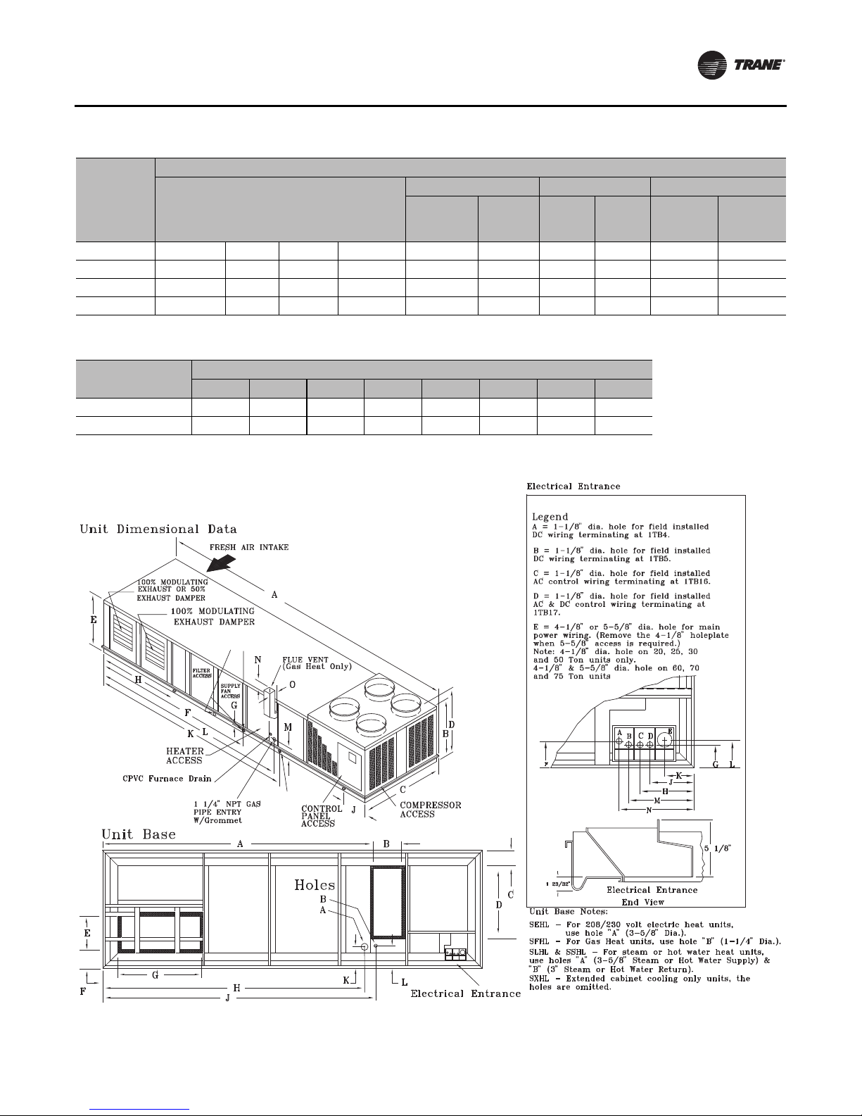
Installation
Table 7. SAHL cooling-only units (20 - 75)
Dimensions for SAHL
E F G
Unit Size
20 - 30 Ton 14'-0 1/4" 2'-2 1/2" 11 3/4" 5'-7" 3'-4 3/8" 2'-9 15/16” 5 13/16" 28 5/8” 6'-6 15/16" 3'
40 - 50 Ton 16'-1 13/16” 2'-5" 11 3/4" 5'-7" 3'-4 3/8" 3' - 1 1/2” 5 13/16" 32 15/16” 7'-8 3/16" 3'-4”
60 Ton 16'-1 13/16” 2'-5" 1'-4 9/16" 6'-10 7/8" 4'-5 3/8" 4' - 2 1/2” 5 13/16" 26 7/16” 7'-8 3/16" 4'-5”
70 - 75 Ton 16'-1 13/16” 2'-5" 1'-4 9/16" 6'-10 7/8" 4'-5 3/8" 4' - 2 1/2” 5 13/16" 26 7/16” 7'-8 3/16" 4'-5”
A B C D
w/exhaust
fan
w/return
fan
w/
exhaust
fan
Table 8. SAHL cooling-only units (20 - 75)
Dimensions
Unit Size
20, 25, 30 & 50 Ton 8 7/32" 6 31/32" 15 21/32" 13 21/32" 9 17/32" 8 1/2" 18 1/16" 19 9/16"
40, 60, 70 & 75 Ton 8 3/4" 7 3/4" 17 7/8" 15 7/8" 9 29/32" 10 1/16" 20 13/32" 22 5/32"
F G H J K L M N
Figure 15. SEHL, SFHL, SLHL, SSHL, SXHL units (20 - 89 ton) use Table 9, Table 10 and Table 11.
w/
return
fan
w/exhaust
fan
w/return
fan
1” NPT CONDENSATE
DRAIN CONNECTION (Both Sides)
DRAIN HOLE
RT-SVX36K-EN 29
Page 30

Installation
Table 9. SEHL, SFHL, SLHL, SSHL, SXHL units (20 - 89 ton)
Air-Cooled Unit Dimensions
Unit Size
20 & 25 Ton 24'-1 3/8" 6’-9” 7'-6 1/2" 7’-3 1/4” 3'-9 5/16" 13'-3" 1" 7' 1'-3 1/2" 16'-7" 16'-6" 8 1/8" 6 1/4" 9"
30 Ton 24'-1 3/8" 6’-9” 7'-6 1/2" 7’-3 1/4” 4'-9 5/16" 13'-3" 1" 7' 1'-3 1/2" 16'-7" 16'-6" 8 1/8" 6 1/4" 9"
40 Ton 32'-10 1/2” 6’-9” 7'-6 1/2" 7’-3 1/4” 5'-9 5/16" 15'-11 1/8" 1" 8' 2'-5" 19'-7"
50 Ton 32'-10 1/2" 6’-9” 7'-6 1/2" 7’-3 1/4” 6'-9 5/16" 15'-11 1/8" 1" 8' 2'-5" 19'-7"
60 Ton 32'-10 1/2” 6’-9” 9'-8" 7’-3 1/4” 5'-9 5/16" 15'-11 1/8" 1" 8' 2'-5" 19'-7"
70 & 75 Ton 32'-10 1/2” 6’-9” 9'-8" 7’-3 1/4” 5'-9 5/16" 15'-11 1/8" 1" 8' 2'-5” 19'-7"
Table 10. SEHL, SFHL, SLHL, SSHL, SXHL units (20 - 89 ton)
Unit Size
24 & 39 Ton 26’5 1/2” 6’-9” 7’-6 1/2” 8’-4 3/4” 3’-9 5/16” 13’-3” 1" 7” 1'-3 1/2" 16'-7" 16'-6" 8 1/8" 6 1/4" 9"
36 Ton 26’5 1/2” 6’-9” 7’-6 1/2” 8’-4 3/4” 4’-9 5/16” 13’-3” 1" 7” 1'-3 1/2" 16'-7" 16'-6" 8 1/8" 6 1/4" 9"
48 Ton 32’-10 1/2” 6’-9” 7’-6 1/2” 8’-4 3/4” 5’-9 5/16” 15’-11 1/8” 1" 8” 2'-5" 19'-7"
59 Ton 32’-10 1/2” 6’-9” 7’-6 1/2” 8’-4 3/4” 6’-9 5/16” 15’-11 1/8” 1" 8” 2'-5" 19'-7"
73 Ton 32’-10 1/2” 6’-9” 9’-8” 8’-4 3/4” 5’-9 5/16” 15’-11 1/8” 1" 8” 2'-5" 19'-7"
80 & 89 Ton 32’-10 1/2” 6’-9” 9’-8” 8’-4 3/4” 5’-9 5/16” 15’-11 1/8” 1" 8” 2'-5” 19'-7"
Note: 19'-6” for SFHL “High Heat” units or 20'-3” for SFHL “Low Heat” units.
A B C D E F G H J K L M N O
See
8 1/8" 6 1/4" 9"
Note
See
8 1/8" 6 1/4" 9"
Note
See
8 1/8" 6 1/4" 9"
Note
See
8 1/8" 6 1/4" 9"
Note
Evaporative Condensing Unit Dimensions
A B C D E F G H J K L M N O
See
8 1/8" 6 1/4" 9"
Note
See
8 1/8" 6 1/4" 9"
Note
See
8 1/8" 6 1/4" 9"
Note
See
8 1/8" 6 1/4" 9"
Note
Table 11. SEHL, SFHL, SLHL, SSHL, SXHL units (20 - 89 ton)
Dimensions
E
w/
Unit Size
(AC/EC)
20-30
/24-36 Ton
40 & 50
/48 & 59 Ton
60/73 Ton 19'-10 5/16" 2'-5" 6 1/16" Note 1 4'-5 3/8" 4'-2 1/2” 5 13/16" 7'-8 3/16" 4'-5” 5 13/16" 26 7/16”
70-75
/80-89 Ton
A B C D
16'-3 3/16" 2'-2 1/2" 5 13/16" 5'-7" 3'-4 3/8" 2'-9 15/16” 5 13/16" 6'-6 15/16" 3' 5 13/16" 28 5/8”
19'-10 5/16" 2'-5" 7 1/16" 5'-7" 3'-4 3/8" 3'-1 1/2” 5 13/16" 7'-8 3/16" 3'-4” 5 13/16" 32 15/16”
19'-10 5/16" 2'-5" 6 1/16" Note 1 4'-5 3/8" 4'-2 1/2” 5 13/16" 7'-8 3/16" 4'-5” 5 13/16" 26 7/16”
exhaust
fan
w/
return fan
exhaust
F
HJKL
20-30
/24-36 Ton
40 & 50
/48 & 59 Ton
60/73 Ton 18'-11 11/16" Note 2 8 3/16" 9 1/16"
70-75
/80-89 Ton
Notes:
1. 5'-5 15/16” for SEHL units or 7'-8 1/2” for SFHL, SLHL, SSHL, SXHL units.
2. 20'-1 3/4” for SFHL “High Heat” units or 20'-6 3/4” for SFHL “Low Heat” units. Either is selectable in field for SL and SS Return.
15'-5 5/16" 16'-9 3/4" 8 13/16" 9 1/16"
18'-11 11/16" Note 2 8 3/16" 9 1/16"
18'-11 11/16" Note 2 8 3/16" 9 1/16"
G F
w/
w/
return
fan
fan
w/
exhaust
fan
return
w/
fan
30 RT-SVX36K-EN
Page 31

Figure 16. Evaporative condenser water connection locations
Installation
A
B
Drain Connection
1 1/4” PVC, Female
A
Tons
(EC)
24, 29 & 36 Ton 5’ 6'-7 5/16" 12" 12 15/16"
48 & 59 Ton 6'-10 7/8" 8'-6 1/8" 12” 12 15/16"
73, 80 & 89 Ton 6'-6 9/16" 8'-6 1/8" 23 11/16" 24 5/8"
B
Drain Connection Inlet Water Connection
A B C D
Water Supply Connection
3/4” PVC, Female
19 13/16"
8 3/16"
C
D
RT-SVX36K-EN 31
Page 32

Installation
Unit Size
(AC/EC)
20, 25 & 30 Ton 8 7/32" 6 31/32" 15 21/32" 13 21/32" 9 17/32" 8 1/2" 18 1/16" 19 9/16"
40-75 / 24-89 Ton 8 15/16” 7 15/16” 17 7/8" 15 7/8" 9 29/32" 10 3/16” 20 13/32" 22 5/32"
Dimensions
F G H J K L M N
Unit Size Dimensions (Note)
(AC/EC) Furnace Size/MBH Length Height
20 & 25, 24 & 29 Ton
30, 36 Ton
40, 48 Ton
50-75, 59-89 Ton
Note: The length dimension is from the exhaust end of the unit. The height dimension is from the bottom of the unit base rail.
Low = 235 195-5/32" 9-5/32"
High = 500 195-5/32" 9-5/32"
Low = 350 195-5/32" 9-5/32"
High = 500 195-5/32" 9-5/32"
Low = 350 240-1/8" 9-5/32"
High = 850 231-1/8" 9-5/32"
Low = 500 240-1/8" 9-5/32"
High = 850 231-1/8" 9-5/32"
32 RT-SVX36K-EN
Page 33

Figure 17. S_HK cooling and heating units (90-130 ton)
14’ - 1/4”
20’ - 2 1/2”
19’ - 3/8”
Installation
(See CPVC Dimensional Table)
RT-SVX36K-EN 33
Page 34

Installation
Figure 18. Center of gravity data
Table 12. Center of gravity data
Units without 100%
Exhaust/Return Fan
Unit Model Unit Size
20 13’ 6” 4’ 10” 13’ 10” 4’ 9” 12’ 4” 4’ 10”
25 14’ 6” 4’ 10” 13’ 11” 4’ 9” 12’ 4” 4’ 10”
30 13’ 11” 4’ 10” 12’ 1” 4’ 9” 12’-8” 4’ 10”
SAHL
SEHL, SLHL,
SSHL, SXHL
SFHL
SXHK,SEHK,
SLHK,SSHK
SFHK
SXHK, SEHK,
SLHK, SSHK
SFHK
Note: Dimensions shown for the center-of-gravity are approximate and are based on a unit equipped with: Standard coils, FC Fans, 100% economizer,
throwaway filters, 460 volt XL start, high capacity heat (as applicable).
40 17’ 4” 4’ 0” 16’ 2” 4’ 11” 16’ 7” 4’ 11”
50 18’ 6” 4’ 0” 16’ 4” 4’ 11” 16’ 9” 4’ 11”
55 18’ 6” 4’ 0” 16’ 5” 4’ 11” 16’ 9” 4’ 11”
60 17’ 0” 5’ 10” 16’ 9” 5’ 8” 15’ 2” 5’ 9”
70 17’ 0” 5’ 10” 16’ 10” 5’ 8” 15’ 3” 5’ 9”
75 18’ 6” 5’ 10” 16’ 4” 5’ 8” 16’ 9” 5’ 9”
20 15’ 8” 4’ 9” 14’ 0” 4’ 8” 13’ 5” 4’ 9”
25 15’ 8” 4’ 9” 14’ 0” 4’ 8” 13’ 6” 4’ 9”
30 14’ 1” 4’ 9” 13’ 3” 4’ 8” 13’ 8” 4’ 9”
40 18’ 4” 4’ 11” 17’ 2” 4’ 10” 17’ 6” 4’ 10”
50 19’ 1” 4’ 0” 18’ 11” 4’ 11” 17’ 2” 4’ 11”
55 19’ 1” 4’ 0” 18’ 11” 4’ 11” 17’ 3” 4’ 0”
60 18’ 6” 5’ 9” 17’ 2” 5’ 7” 17’ 6” 5’ 8”
70 18’ 3” 5’ 10” 17’ 11” 5’ 8” 16’ 4” 5’ 9”
75 19’ 2” 5’ 10” 18’ 10” 5’ 8” 17’ 2” 5’ 9”
20 15’ 9” 4’ 10” 14’ 1” 4’ 9” 14’ 7” 4’ 10”
25 15’ 10” 4’ 9” 14’ 2” 4’ 8” 14’ 7” 4’ 9”
30 14’ 2” 4’ 9” 13’ 4” 4’ 8” 13’ 10” 4’ 9”
40 19’ 6” 4’ 11” 17’ 4” 4’ 10” 17’ 9” 4’ 10”
50 19’ 1” 4’ 11” 18’ 0” 4’ 10” 17’ 4” 4’ 11”
55 19’ 2” 4’ 11” 18’ 0” 4’ 10” 17’ 4” 4’ 11”
60 19’ 7” 5’ 9” 17’ 4” 5’ 7” 17’ 8” 5’ 9”
70 18' 3” 5’ 9” 17’ 0” 5’ 7” 16’ 5” 5’ 8”
75 19’ 2” 5’ 9” 18’ 10” 5’ 7” 17’ 3” 5’ 9”
90 18’ 9” 5’ 10” 20’ 4” 6’ 2” 17’ 9” 5’ 10”
105 19’ 1” 5’ 11” 20’ 7” 6’ 2” 18’ 1” 6’ 0”
90 18’ 11” 6’ 0” 20’ 6” 6’ 3” 17’ 10” 5’ 11”
105 19’ 3” 6’ 0” 20’ 9” 6’ 4” 18’ 4” 6’ 7”
115 19’ 2” 5’ 10” 20’ 8” 6’ 2” 18’ 1” 6’ 0”
130 19’ 5” 5’ 10” 20’ 11” 6’ 2” 18’ 6” 6’ 0”
115 19’ 4” 6’ 0” 20’ 9” 6’ 3” 18’ 3" 6’ 1”
130 19’ 6” 6’ 0” 21’ 10” 6’ 3” 18’ 8” 6’ 0”
Dim. A Dim. B Dim. A Dim B. Dim. A Dim. B
Units with
Exhaust/Return Fan
Units with Supply &
Exhaust/Return VFD
34 RT-SVX36K-EN
Page 35

Installation
Table 13. Air-cooled condenser - approximate operating weights (Lbs./Kg)
Without Exhaust Fan With Exhaust Fan
Unit
20
25
30
40
50
55
60
70
75
90
105
115
130
Notes:
1. Weights shown for air-cooled units include the following features: FC fans, standard coils, 100% economizer, throw-away filters, maximum motor
sizes 460V XL, high heat.
2. Weights shown represent approximate operating weights and have a ±5% accuracy. To calculate weight for a specific unit configuration, utilize
TOPSS™ or contact the local Trane sales representative. ACTUAL WEIGHTS ARE STAMPED ON THE UNIT NAMEPLATE.
Lb 4092 4422 4712 4422 4312 4390 4720 5010 4720 4610
Kg 1856 2006 2137 2006 1956 1991 2141 2272 2141 2091
Lb 4181 4521 4791 4521 4391 4485 4825 5095 4825 4695
Kg 1896 2050 2173 2050 1992 2034 2188 2311 2188 2129
Lb 4572 4932 5202 4932 4812 5029 5389 5659 5389 5269
Kg 2074 2237 2359 2237 2183 2281 2444 2567 2444 2390
Lb 6433 6737 7217 6737 6577 7103 7407 7887 7407 7247
Kg 2918 3056 3273 3056 2983 3222 3360 3577 3360 3287
Lb 7175 7725 8185 7725 7555 7894 8444 8904 8444 8274
Kg 3255 3504 3713 3504 3427 3581 3830 4039 3830 3753
Lb 7425 7975 8455 7975 7815 8144 8694 9174 8694 8534
Kg 3368 3617 3835 3617 3545 3694 3944 4161 3944 3871
Lb 8338 8658 9118 8658 8498 9282 9602 10062 9602 9442
Kg 3782 3927 4136 3927 3855 4210 4355 4564 4355 4283
Lb 8604 8666 9146 8666 8516 9547 9609 10089 9609 9459
Kg 3903 3931 4148 3931 3863 4330 4358 4576 4358 4290
Lb 8843 9173 9653 9173 9023 9786 10116 10596 10116 9966
Kg 4011 4161 4379 4161 4093 4439 4589 4806 4589 4521
Lb. N/A 12649 12799 13439 12919 N/A 13989 14139 14779 14259
Kg N/A 5737 5805 6096 5860 N/A 6345 6413 6704 6468
Lb. N/A 13259 13409 14049 13529 N/A 14599 14749 15389 14869
Kg N/A 6014 6082 6372 6137 N/A 6622 6690 6980 6744
Lb. N/A 13449 13629 14289 13649 N/A 14789 14969 15629 14989
Kg N/A 6100 6182 6481 6191 N/A 6708 6790 7089 6799
Lb. N/A 13899 14059 14699 14089 N/A 15239 15399 16039 15429
Kg N/A 6304 6377 6667 6391 N/A 6912 6985 7275 6998
SA SX SE SF SL/SS SA SX SE SF SL/SS
RT-SVX36K-EN 35
Page 36

Installation
Table 14. Evaporative condenser - approximate operating weights (lbs/kg)
Without Exhaust Fan With Exhaust Fan
Unit SX SE SF SL/SS SX SE SF SL/SS
24
29
36
48
59
73
80
89
Notes:
1. Weights shown for evaporative condensing units include the following features: FC fans, high capacity evaporative coil. Add 520 lbs for 24, 29, 36, 48
and 59 units and 680 lbs for 73, 80 and 89 units for installed sump base water weight for evaporative condenser total operating weight.
2. Weights shown represent approximate operating weights and have a ±5% accuracy . To calculate weight for a specific unit configuration, utilize TOPSS
or contact the local Trane sales representative. ACTUAL WEIGHTS ARE STAMPED ON THE UNIT NAMEPLATE.
lbs 6549 6679 6944 6763 6907 7037 7302 7121
kg 2971 3030 3150 3068 3133 3192 3312 3230
lbs 6599 6729 6994 6813 6963 7093 7358 7177
kg 2993 3052 3172 3090 3158 3217 3338 3255
lbs 7121 7251 7513 7335 7538 7668 7933 7752
kg 3230 3289 3409 3327 3419 3478 3598 3516
lbs 9001 9156 9631 9359 9585 9740 10215 9943
kg 4083 4153 4369 4245 4348 4418 4633 4510
lbs 9213 9368 9843 9571 9856 10011 10486 10214
kg 4179 4249 4465 4341 4471 4541 4756 4633
lbs 11303 11458 11933 11691 12128 12283 12758 12516
kg 5127 5197 5413 5303 5501 5571 5787 5677
lbs 11430 11585 12060 11818 12255 12410 12885 12643
kg 5185 5255 5470 5361 5559 5629 5845 5735
lbs 11820 11975 12450 12208 12645 12800 13275 13033
kg 5361 5432 5647 5537 5736 5806 6021 5912
Table 15. Roof curb max weight
Roof Curb Max. Weight
Unit
20/24
25/29
30/36
40/48
50/55/59
60/73
(a)Roof curb weights include the curb and pedestal.
SAHL S*HL SAHL S*HL
490 510
222 231 277 290
490 510
222 231 277 290
490 510
222 231 N/A 349
515 550
234 249 N/A 349
515 550
234 249 N/A 349
515 550
234 249 N/A 349
(a)
Trane Roof Curb and Ductwork
The roof curbs for 20 through 130Ton units consists of two
main components; a pedestal to support the unit’s
condenser section and a “full perimeter” enclosure to
support the unit’s air handler section.
Before installing any roof curb, verify;
1. That it is the correct curb for the unit,
2. That it includes the necessary gaskets and hardware,
Roof Curb Max. Weight
Unit
70/80
75/89
90
105
115
130
610 640
610 640
N/A 770
N/A 770
N/A 770
N/A 770
3. That the purposed installation location provides the
required clearance for proper operation.
4. Insure that the curb is level and square.The top surface
of the curb must be true to assure an adequate curb-tounit seal.
Step-by-step curb assembly and installation instructions
ship with eachTrane accessory roof curb kit. Follow the
instructions carefully to assure proper fit-up when the unit
is set into place.
36 RT-SVX36K-EN
Page 37

Installation
Note: To assure proper condensate flow during
operation, the unit (and curb) must be as level as
possible.The maximum slope allowable for
rooftop unit applications, excluding SSH_'s, is 4"
end-to-end and 2" side-to-side. Units with steam
coils (SSH_'s) must be set level!
If the unit is elevated, a field constructed catwalk around
the unit is strongly recommended to provide easy access
for unit maintenance and service.
Recommendations for installing the Supply Air and Return
Air ductwork joining the roof curb are included in the curb
instruction booklet. Curb ductwork must be fabricated and
installed by the installing contractor before the unit is set
into place.
Note: For sound consideration, cut only the holes in the
roof deck for the ductwork penetrations. Do not cut
out the entire roof deck within the curb perimeter.
Pitch Pocket Location
The location of the main supply power entry for S_HL 20
through 89Ton rooftop units is located at the bottom righthand corner of the control panel.
Figure 14 and Figure 15 illustrate the location for the
electrical entrance through the base in order to enter the
control panel. If the power supply conduit penetrates the
building’s roof beneath this opening, it is recommended
Figure 19. Pitch pocket location
that a pitch pocket be installed before the unit is placed
onto the roof curb.
The center line dimensions shown in the illustration below
indicates the center line of the electrical access hole in the
unit base when it is positioned on the curb, ±3/8 inch.The
actual diameter of the hole in the roof should be at least 1/
2 inch larger than the diameter of the conduit penetrating
the roof.This will allow for the clearance variable between
the roof curb rail and the unit base rail illustrated in
Figure 19.
The pitch pocket dimensions listed are recommended to
enhance the application of roofing pitch after the unit is set
into place.The pitch pocket may need to be shifted as
illustrated to prevent interference with the curb pedestal.
Table 16. Pitch pocket dimensions
Unit Tonnage “A” Dimension "B" Dimension
S*HL 20, 25 & 30 4' 5-9/16" 5-9/16"
S*HL 24, 29, & 36 6' 9-11/16” 5-1/2”
S*HL 40 - 89 9' 5-11/16" 5-1/2"
* = All unit functions (SAHL, SEHL, SFHL, SSHL, SLHL and SXHL)
Notes: For design special evaporative-cooled condensing units, please
see the curb installers guide for proper pitch pocket locations.
If a Trane Curb Accessory Kit is Not Used:
a. The ductwork can be attached directly to the
factory-provided flanges around the unit’s supply
and return air openings. Be sure to use flexible duct
connections at the unit.
b. For “built-up” curbs supplied by others, gaskets
must be installed around the curb perimeter flange
and the supply and return air opening flanges.
Notes:
RT-SVX36K-EN 37
• If a “built-up” curb is provided by others, keep in mind
that these commercial rooftop units do not have base
pans in the condenser section.
• If this is a REPLACEMENT UNIT keep in mind that the
CURRENT DESIGN commercial rooftop units do not
have base pans in the condenser section.
• Trane roof curbs are recommended. If using a non-
Trane roof curb with right-angle return airflow
approaches to a return fan inlet, a rigid, solid flow
baffle wall should be installed across the full width of
the roof curb return airflow path in the position shown
in Figure 20, p. 38 to reduce potential airflow
Page 38

Installation
disturbances at the return fan inlet that could
contribute to unusual return fan noise.
• If a full perimeter curb is used, make sure the IRU
option was added to the unit to ensure stability in the
condenser section
Figure 20. Solid flow baffle wall installation for non-
Trane roof curbs
Return Fan
Roof Curb
Flow Baffle
Return Airflow
Return Airflow
Duct
3. Test-lift the unit to ensure it is properly rigged and
balanced, make any necessary rigging adjustments.
4. Lift the unit and position it over the curb and pedestal.
(These units have a continuous base rail around the air
handler section which matches the curb.
5. Align the base rail of the unit’s air handler section with
the curb rail while lowering the unit onto the curb.
Make sure that the gasket on the curb is not damaged
while positioning the unit. (The pedestal simply
supports the unit’s condenser section)
A cross section of the juncture between the unit and the
roof curb is shown in Figure 22, p. 39.
Unit Rigging & Placement
WARNING
Heavy Objects!
Ensure that all the lifting equipment used is properly
rated for the weight of the unit being lifted. Each of the
cables (chains or slings), hooks, and shackles used to
lift the unit must be capable of supporting the entire
weight of the unit. Lifting cables (chains or slings) may
not be of the same length. Adjust as necessary for even
unit lift. Other lifting arrangements could cause
equipment or property damage. Failure to follow
instructions above or properly lift unit could result in
unit dropping and possibly crushing operator/
technician which could result in death or serious injury.
Note: Use spreader bars as shown in the diagram. Refer
to the Installation manual or nameplate for the unit
weight. Refer to the Installation Instructions
located inside the side control panel for further
rigging information.
1. A Center-of-Gravity illustration and the dimensional
data is shown in Figure 18, p. 34 and Table 12, p. 34.
2. Attach adequate strength lifting slings to all four lifting
lugs on 20 through 75Ton units. The minimum
distance between the lifting hook and the top of the
unit should be 7 feet for 20 through 75Ton units.
Figure 21, p. 39 illustrates the installation of spreader
bars to protect the unit and to facilitate a uniform lift.
Table 13, p. 35 lists the typical unit operating weights.
38 RT-SVX36K-EN
Page 39

Figure 21. Unit rigging
Installation
Figure 22. Typical unit base and roof curb cross section
RT-SVX36K-EN 39
Page 40

Installation
General Unit Requirements
WARNING
Live Electrical Components!
During installation, testing, servicing and
troubleshooting of this product, it may be necessary to
work with live electrical components. Have a qualified
licensed electrician or other individual who has been
properly trained in handling live electrical components
perform these tasks. Failure to follow all electrical
safety precautions when exposed to live electrical
components could result in death or serious injury.
The checklist listed below is a summary of the steps
required to successfully install a Commercial rooftop unit.
This checklist is intended to acquaint the installing
personnel with what is required in the installation process.
It does not replace the detailed instructions called out in
the applicable sections of this manual.
• Check the unit for shipping damage and material
shortage; file a freight claim and notifyTrane office.
• Verify that the installation location of the unit will
provide the required clearance for proper operation.
• Assemble and install the roof curb per the current
edition of the curb installation guide.
• Fabricate and install ductwork; secure ductwork to
curb.
• Install pitch pocket for power supply through building
roof. (If applicable)
• Rigging the unit.
• Set the unit onto the curb; check for levelness.
• Ensure unit-to-curb seal is tight and without buckles or
cracks.
• Install and connect condensate drain lines to each
evaporator drain connection.
• Remove the shipping hold-down bolts and shipping
channels from the supply and exhaust/return fans with
rubber or spring isolators.
• Check all optional supply and exhaust/return fan
spring isolators for proper adjustment.
• Verify all discharge and liquid line service valves (one
per circuit) are back seated.
Main Electrical Power Requirements
• Verify that the power supply complies with the unit
nameplate specifications.
• Inspect all control panel components; tighten any
loose connections.
• Connect properly sized and protected power supply
wiring to a field-supplied/installed disconnect and unit
• Properly ground the unit.
Note: All field-installed wiring must comply with NEC
and applicable local codes.
Field Installed Control Wiring
• Complete the field wiring connections for the constant
volume controls as applicable. Refer to “Field Installed
Control Wiring” for guidelines.
• Complete the field wiring connections for the variable
air volume controls as applicable. Refer to “Field
Installed Control Wiring” for guidelines.
Note: All field-installed wiring must comply with NEC
and applicable local codes.
Requirements for Electric Heat Units
All SEHL and SEHK Units (380 minimum
voltage).
• Verify that the power supply complies with the electric
heater specifications on the unit and heater nameplate.
• Inspect the heater junction box and control panel;
tighten any loose connections.
• Check electric heat circuits for continuity.
SEHL Units w/200V or 230V Electric Heat:
(Requires Separate Power Supply to Heater)
• Connect properly sized and protected power supply
wiring for the electric heat from a dedicated, fieldsupplied/installed disconnect to terminal block 4TB2,
or to an optional unit mounted disconnect switch 4S15.
Requirements for Gas Heat (SFH_)
• Gas supply line properly sized and connected to the
unit gas train.
• All gas piping joints properly sealed.
• Drip leg Installed in the gas piping near the unit.
• Gas piping leak checked with a soap solution. If piping
connections to the unit are complete, do not pressurize
piping in excess of 0.50 psig or 14 inches w.c. to
prevent component failure.
• Main supply gas pressure adequate.
• FlueTubes clear of any obstructions.
• Factory-supplied flue assembly installed on the unit.
• Connect the 3/4” CPVC furnace drain stubout to a
proper condensate drain.
Requirements for Hot Water Heat (SLH_)
• Route properly sized water piping through the base of
the unit into the heating section.
• Install the factory-supplied, 3-way modulating valve.
• Complete the valve actuator wiring.
40 RT-SVX36K-EN
Page 41

Installation
Requirements for Steam Heat (SSH_)
• Install an automatic air vent at the top of the return
water coil header.
• Route properly sized steam piping through the base of
the unit into the heating section.
• Install the factory-supplied, 2-way modulating valve
• Complete the valve actuator wiring.
• Install 1/2”, 15-degree swing-check vacuum breaker(s)
at the top of each coil section. Vent breaker(s) to the
atmosphere or merge with return main at discharge
side of steam trap.
• Position the steam trap discharge at least 12" below the
outlet connection on the coil.
• Use float and thermostatic traps in the system, as
required by the application.
O/A Pressure Sensor and Tubing
Installation (All units with Statitrac or
Return Fans)
• O/A pressure sensor mounted to the roof bracket.
• Factory supplied pneumatic tubing installed between
the O/A pressure sensor and the connector on the
vertical support.
• Field supplied pneumatic tubing connected to the
proper fitting on the space pressure transducer located
in the filter section, and the other end routed to a
suitable sensing location within the controlled space
(Statitrac only).
Figure 23. Condensate drain locations
Requirements for Modulating Reheat
Dehumidification (S_HL)
• Install (5U108) humidity sensor in space or return duct
• Complete field wiring of humidity sensor to ECEM
(1TB16). Refer to “Field Installed Control wiring” for
guidelines.
Condensate Drain Connections
Each S_HL and S_HK unit is provided with 1" evaporator
condensate drain connections (two on each side of the unit
for FC supply fans and one on eachside of the unit for DDP
supply fans).
Due to the size of these units, all condensate drain
connections must be connected to the evaporator drain
connections. Refer to the appropriate illustration in
Figure 14 and Figure 15 for the location of these drain
connections.
Condensate traps must be installed because drain
connections are in a negative pressure environment.
Install the P-Traps at the unit using the guidelines in
Figure 24.
Pitch the drain lines at least 1/2 inch for every 10 feet of
horizontal run to assure proper condensate flow. Do not
allow the horizontal run to sag causing a possible doubletrap condition which could result in condensate backup
due to “air lock”.
RT-SVX36K-EN 41
Condensate drain openings
both sides
Note: Each drain pan connection must be trapped.
The drains may be trapped individually or
connected and then trapped.
Page 42

Installation
Units with Gas Furnace
Units equipped with a gas furnace have a 3/4” CPVC drain
connection stubbed out through the vertical support in the
gas heat section. It is extremely important that the
condensate be piped to a proper drain. Refer to the
appropriate illustration in Figure 14 and Figure 15 for the
location of the drain connection.
Note: Units equipped with an optional modulating gas
furnace will likely operate in a condensing mode
part of the time.
An additional 1-1/4” non-connectable water drain is
located in the base rail within the heating section.
Ensure that all condensate drain line installations comply
with applicable building and waste disposal codes.
Figure 24. Condensate trap installation
L
G
4. Verify that the fan assembly is being supported by the
isolators.
Spring Isolators: See Figure 26, Figure 28, Figure 27
and Figure 29 for spring isolator locations.
1. Remove and discard the shipping tie down bolts.
2. Remove the shipping channels and discard.
Note: Fan assemblies not equipped with rubber or spring
isolators have mounting bolts at the same
locations and must not be removed.
Note: If return fan backside spring isolator repair/
replacement is required, access the backside of the
return fan by entering the unit filter section.
Remove the top pivot bearings from the three
fixed- position return damper blades (bolted
together as a single section with an angle brace).
Lift the three-blade section as a single unit from the
return damper assembly and set aside or lean in
against the return fan frame.Then enter the return
fan compartment from the filter section to perform
service work on the rear isolators.
Optional DDP Supply Fan Shipping
Channel Removal and Isolator Spring
Adjustment
Removing Supply and Exhaust/Return Fan
Shipping Channels (Motors >5Hp)
Each FC supply fan assembly and exhaust fan assembly
for S_HL units shipped with a motor larger than 5 HP is
equipped with rubber isolators (as standard) or optional
spring isolators. Each DDP supply fan assembly for SAHF
and SXHL units is equipped with spring isolators. Each
return fan assembly for S_HL units shipped with a motor
larger than 5 HP is equipped with spring isolators.
Shipping channels are installed beneath each fan
assembly and must be removed.To locate and remove
these channels, refer to Figure 26 and Figure 28, and use
the following procedures:
Rubber Isolators:
1. Remove and discard the shipping bolts from the fan
assembly rails.
2. Elevate the fan-and-motor assembly and slide the
shipping channels out from between the fan assembly
rails and the unit's base rail.
3. Lower the fan-and-motor assembly onto the isolators.
Make sure that the pins at the top of the isolators are
engaged in the corresponding holes on the fan
assembly.
ShippingTie Down and Isolator Spring AdjustmentRemove shipping tie down bolt and washer (4 - 20 to 30
ton,6-40to55ton,8-60to75ton). Leave shipping
channels in place. Verify spring height is 0.1" to 0.2"
above shipping channel. Spring height is factory set but
verify and adjust as needed by: 1) Back off ALL spring
isolator jam nuts (4) at top of assembly (adjusting one
spring effects all others) 2)Turn adjustment bolt (make
small adjustments, again each change effects all other
springs. Clockwise raises, Counter clockwise lowers).
When correctly adjusted re-tighten jam nuts and remove
shipping channels. Do Not Remove electrical
ground wire strap between isolation base and unit
base.
42 RT-SVX36K-EN
Page 43

Figure 25. DDP shipping channel removal, isolator spring adjustment
Figure 26. Removing supply and exhaust fan assembly shipping hardware (20-89 Ton)
Installation
RT-SVX36K-EN 43
Page 44

Installation
Figure 27. Removing supply and exhaust fan assembly shipping hardware (90-130 Ton)
Figure 28. Removing return fan assembly shipping hardware (20-89 Ton)
44 RT-SVX36K-EN
Page 45

Installation
O/A Sensor & Tubing Installation
An Outside Air Pressure Sensor is shipped with all units
designed to operate on variable air volume applications,
units equipped with a return fan, or constant volume units
with 100% modulating exhaust w/Statitrac.
On VAV systems, a duct pressure transducer (3U60) and
the outside air sensor is used to control the discharge duct
static pressure to within a customer-specified parameter.
On CV & VAV units equipped with 100% modulating
exhaust w/Statitrac, a space pressure transducer (3U62)
and the outside air sensor is used to control the exhaust
fan and dampers to relieve static pressure to within a
customer-specified parameter within the controlled space.
On units equipped with a return fan, a return pressure
transducer (3U106) is connected to the
O/A sensor for comparison with return plenum pressure.
Refer to Figure 29, p. 47 and the following steps to install
the sensor and the pneumatic tubing.
1. Remove the O/A pressure sensor kit located inside the
filter section.The kit contains the following items;
• O/A static pressure sensor with sensor mounting
• Bracket
• 50' of 3/16” O.D. pneumatic tubing
• Mounting hardware
2. Using two #10-32 x 1-3/4” screws provided, install the
sensor's mounting bracket to the factory installed
bracket (near the filter section).
3. Using the #10-32 x 1/2” screws provided, install the O/
A static pressure sensor vertically to the sensor
bracket.
4. Remove the dust cap from the tubing connector
located below the sensor in the vertical support.
5. Attach one end of the 3/16” O.D. factory provided
pneumatic tubing to the sensor's top port, and the
other end of the tubing to the connector in the vertical
support. Note that most of the tubing is not needed.
Discard any excess tubing.
Units with Statitrac:
6. Open the filter access door, and locate the pressure
transducer mounting plate illustrated in Figure 29.
There are three tube connectors mounted on the left of
the solenoid and transducers. Connect one end of the
field provided 3/16” O.D. pneumatic tubing for the
space pressurization control to the bottom fitting.
Route the opposite end of the tubing to a suitable
location inside the building.This location should be
the largest open area that will not be affected by
sudden static pressure changes.
Remove Evaporative Condenser Fan Shipping
Brackets
To remove shipping brackets
Important: Remove fan shipping brackets before
startup. Failure to remove brackets could
result in fan damage.
Evaporative condensers are shipped with fan shipping
brackets to reduce damage caused by vibration during
shipment.The fan shipping brackets must be removed
prior to unit startup.To remove the shipping brackets start
from the side opposite to the drain actuator (see Figure 85,
p. 131):
1. Loosen the screw for the bracket that holds the inlet
louvers below the door side.
2. Remove inlet louvers and set to the side.
Note: Service technician may need to step on the
horizontal surface of FRP coated base.
Step with care.
3. Unscrew the bolt in the middle of the door. Keep the
bolt in a safe place.
4. Lift one door with handle until it touches the top.
Swivel bottom of door to remove it from the door
opening and set it to the side.
5. Slide and remove the middle mist eliminator section
so that the shipping bracket is visible.
6. Use screw gun to unscrew the two screws that hold the
fan shipping bracket.The bracket should drop down
but still remain engaged with a hook on the bracket.
7. Go to the other side of the unit and follow the
procedure for inlet louver and door removal (see steps
1 - 6).
8. Hold the bracket with one hand and remove remaining
two screws.
9. Remove the bracket and all the removed screws from
the unit.
Important: Make sure there are no screws remaining in
the coil area.
10. Reinstall inlet louvers, mist eliminators and louvers.
Check that the direction of arrow on the inlet louver is
correct.
Evaporative Condenser Make-upWater
and Drain Line Installation
Make-upWater and Drain Lines
Water Supply Source
The supply line should be designed to provide a minimum
supply of water within customary domestic supply
pressures, 35 to 60 psig; dynamic pressure (measured
with the valve open) which will allow approximately 30
GPM to enter the sump through the makeup water valve,
when the sump is empty.The unit uses about 2-4 GPM.
Attach a hand valve at the inlet for use during inspection
and maintenance; an inlet strainer is recommended as
well.
RT-SVX36K-EN 45
Page 46

Installation
Make-up water inlet connection is a ¾” PVC slip connector.
Care must be taken to ensure the water line upstream of
the water solenoid valve will not freeze. Insulating the line
and utilizing heat tape is recommended if ambient
temperatures below 32° F are expected.
Water Quality
Overall performance of any water-cooled device can be
affected by suspended particulates, mineral
concentration, trash and debris resulting in clogging and
heat transfer loss.The evaporative-cooled condenser is
designed to greatly minimize problems with these
impurities.
However, float valves and solenoid valves are used to
control the incoming water. If the incoming water contains
contaminants, sand or other objects, an incoming line
strainer with a 80 to 100 mesh screen is required.The inlet
line should be flushed prior to connection to the unit,
whether or not there is a strainer.
Note: Backflow preventer to be field provided and
installed by others.
Water Drain Schedule 80 PVC pipe of 1¼” is normally
adequate for sump water drain. Periodically, the sump is
emptied and flushed to eliminate accumulated dirt, debris,
and minerals.
Concentration of these foreign substances will increase as
the system operates.The evaporative process releases
essentially pure water vapor into the atmosphere, leaving
the impurities behind that accumulate in the sump.
Although these impurities are present in the original
make-up water, their concentration will be higher in the
sump discharge. Care and judgment should be exercised
when selecting a discharge site.
water. Operation can be extended to 10 deg by providing
an optional sump heater.
Drain Valve
The drain valve is shipped to “drain during power loss
conditions”. If “hold during power loss conditions” is
desired, refer to “Evaporative Condenser Drain Valve
Setup” on page 89.
Local Site Discharge
Rooftop or simple storm sewer discharge is generally
acceptable. Do not routinely direct the sump discharge
onto an area where these higher concentrations will
adversely affect that area, i.e. continued sump discharge
into a flower bed for example, where the input water
contains CaCO3 (lime) will eventually decrease the pH of
the soil.
Sewer Discharge
The quantities of mineral and debris flushed are actually
very small, and do not cause problems when diluted in
normal sewer flow. However, local, state or federal
standards and restrictions must be followed in any given
locality
Make Up Water Solenoid Valve
This valve is controlled by the UCM based on water level
in the sump, as well as whether a call for mechanical
cooling exists.
During low ambient temperatures, the solenoid valve will
be de-energized preventing water from further filling
sump.The sump drain valve opens to empty sump of
46 RT-SVX36K-EN
Page 47

Figure 29. Pressure sensing
Outside Air Sensing Kit
Duct, Space and Return Plenum Pressure Transducer Tubing Schematic
Return Plenum
Transducer
Sensing Tube
to Return
Plenum
Installation
Duct and Space Static Pressure
Control Component Layout
Space Static
Transducer
(3U62)
Static Reference Tubing
Connects Here
Discharge Duct
Static Tubing
Connects Here
Space Pressure
Sensing Tube
Connects Here
Space Pressure Calibration
Solenoid (3L21)
Supply Air Duct
Static Transducer
(3U60)
Return Fan Plenum Pressure
Control Component Layout
If equipped with Return Fan and
Statitrac, Statitrac Static Reference
Tubing connects here
Static Reference
Tubing Connects
Here (O/A Sensor)
Return Plenum
Sensing Tube
Connects Here
Return Plenum Calibration
Solenoid (3L24)
Return Plenum
Transducer
(3U106)
RT-SVX36K-EN 47
Page 48

Installation
Gas Heat Units (SFH_)
All internal gas piping is factory-installed and pressure
leak-tested before shipment. Once the unit is set into
place, the gas supply line must be field-connected to the
elbow located inside the gas heat control compartments.
WARNING
Hazardous Gases and Flammable Vapors!
Exposure to hazardous gases from fuel substances
have been shown to cause cancer, birth defects or other
reproductive harm. Improper installation, adjustment,
alteration, service or use of this product could cause
flammable mixtures.To avoid hazardous gases and
flammable vapors follow proper installation and set up
of this product and all warnings as provided in this
manual. Failure to follow all instructions could result in
death or serious injury.
When using dry nitrogen cylinders for pressurizing
units for leak testing, always provide a pressure
regulator on the cylinder to prevent excessively high
unit pressures. Never pressurize unit above the
maximum recommended unit test pressure as specified
in applicable unit literature. Failure to properly regulate
pressure could result in a violent explosion, which
could result in death or serious injury or equipment or
property-only-damage.
Access holes are provided on the unit as illustrated in
Figure 15, p. 29 to accommodate a side or bottom pipe
entry on 20 through 89Ton units and in Figure 17, p. 33 on
90-130Ton units. Following the guidelines listed below will
enhance both the installation and operation of the furnace.
Note: In the absence of local codes, the installation must
conform with the American National Standard
Z223-1a of the National Fuel Gas Code, (latest
edition).
1. To assure sufficient gas pressure at the unit, use
Table 24, p. 61 as a guide to determine the appropriate
gas pipe size for the unit heating capacity listed on the
unit's nameplate.
2. If a gas line already exists, verify that it is sized large
enough to handle the additional furnace capacity
before connecting to it.
3. Take all branch piping from any main gas line from the
top at 90 degrees or at 45 degrees to prevent moisture
from being drawn in with the gas.
4. Ensure that all piping connections are adequately
coated with joint sealant and properly tightened. Use a
piping compound that is resistant to liquid petroleum
gases.
5. Provide a drip leg near the unit.
6. Install a pressure regulator at the unit that is adequate
to maintain 7" w.c. for natural gas while the furnace is
operating at full capacity.
Note: Gas pressure in excess of 14" w.c. or 0.5 psig will
damage the gas train.
Failure to use a pressure regulating device will result in
incorrect gas pressure. This can cause erratic operation
due to gas pressure fluctuations as well as damage the gas
valve. Over sizing the regulator will cause irregular
pulsating flame patterns, burner rumble, potential flame
outages, and possible gas valve damage.
If a single pressure regulator serves more than one rooftop
unit, it must be sized to ensure that the inlet gas pressure
does not fall below 7" w.c. with all the furnaces operating
at full capacity.The gas pressure must not exceed 14" w.c.
when the furnaces are off.
7. Provide adequate support for all field installed gas
piping to avoid stressing the gas train and controls.
8. Leak test the gas supply line using a soap-and-water
solution or equivalent before connecting it to the gas
train.
9. Check the supply pressure before connecting it to the
unit to prevent possible gas valve damage and the
unsafe operating conditions that will result.
Note: Do not rely on the gas train shutoff valves to isolate
the unit while conducting gas pressure/leak test.
These valves are not designed to withstand
pressures in excess of 14" w.c. or 0.5 psig.
Connecting the Gas Supply Line to the
Furnace Gas Train
Follow the steps below to complete the installation
between the supply gas line and the furnace. Refer to
Figure 30 through Figure 33 for the appropriate gas train
configuration.
1. Connect the supply gas piping using a “ground-joint”
type union to the furnace gas train and check for leaks.
2. Adjust the inlet supply pressure to the recommended
7" to 14" w.c. parameter for natural gas.
3. Ensure that the piping is adequately supported to
avoid gas train stress.
Table 17. Specific gravity multipliers
Specific Gravity Multiplier
0.50 1.10
0.55 1.04
0.60 1.00
0.65 0.96
48 RT-SVX36K-EN
Page 49

Table 18. Sizing natural gas pipe mains and branches
Gas Input (Cubic Feet/Hour)*
Gas Supply
Pipe Run
(ft)
10 1050 1600 3050 4800 8500 17500
20 730 1100 2100 3300 5900 12000
30 590 890 1650 2700 4700 9700
40 500 760 1450 2300 4100 8300
50 440 670 1270 2000 3600 7400
60 400 610 1150 1850 3250 6800
70 370 560 1050 1700 3000 6200
80 350 530 990 1600 2800 5800
90 320 490 930 1500 2600 5400
100 305 460 870 1400 2500 5100
125 275 410 780 1250 2200 4500
150 250 380 710 1130 2000 4100
175 225 350 650 1050 1850 3800
200 210 320 610 980 1700 3500
* Table is based on a specific gravity of 0.60. Use Table 23 for the specific
gravity of the local gas supply.
1-¼"
Pipe
1-½"
Pipe
2"
Pipe
2-½"
Pipe
3"
Pipe
4"
Pipe
Installation
Table 19. Modulating gas heat settings
Natural Gas
Full Modulation Partial Modulation Gas Valve Settings
Air Damper
Actuator Voltage
Heater Size (MBH) Gas Orifice
500 #21 7 - 10 7 - 9.7 2.3 -1
850 #H 6 - 10 6 - 8.7 1.3 -1
1000 #N 5 - 10 5 - 8.7 0.9 0
Range (VDC)
Full Modulation Partial Modulation Gas Valve Settings
Air Damper
Actuator Voltage
Heater Size (MBH) Gas Orifice
500 #34 / #53 7 - 10 7 - 9.7 6 1
850 #32 6 - 10 6 - 8.7 3.2 1
1000 #29 5 - 10 5 - 8.7 1.9 0
Note: Valve actuator settings are approximate and may require “fine tuning” to properly set. Right (fine) settings given are in notches from the “zero”
midpoint location on sight gage.
Range (VDC)
Air Damper
Actuator Voltage
Range (VDC)
LP
Air Damper
Actuator Voltage
Range (VDC)
Left Setting
Pgas/ Pair
Left Setting
Pgas/ Pair
Right Setting
(Low fire bias)
Right Setting
(Low fire bias)
RT-SVX36K-EN 49
Page 50

Installation
Table 20. Gas heating capacity altitude correction factors
Altitude (Ft.)
Sea Level - 2000 2001 - 2500 2501 - 3500 3501 - 4500 4501 - 5500 5501 - 6500 6501 - 7500
Capacity
Multiplier
Note: Correction factors are per AGA Std. 221.30 - 1964, Part VI, 6.12. Local codes may supersede.
Notes:
1. If more than one unit is served by the same main gas supply, consider the total gas input (cubic feet/hr.) and the total length when determining the
appropriate gas pipe size.
2. Obtain the Specific Gravity and BTU/Cu.Ft. from the gas company.
3. The following example demonstrates the considerations necessary when determining the actual pipe size.
Example: A 40' pipe run is needed to connect a unit with a 500 MBH furnace to a natural gas supply having a rating of 1,000 BTU/Cu.Ft. and a specific gravity of 0.60
Cu.Ft/Hour = Furnace MBH Input
Gas BTU/Cu.Ft. X Multiplier (Table 23)
4. Table 24 indicates that a 1-1/4” pipe is required.
Cu.Ft/Hour = 500
Figure 30. Unit gas trains (natural gas) 235, 350 MBH
1.00 .92 .88 .84 .80 .76 .72
Figure 31. Unit gas trains (natural gas) 500, 850 MBH
50 RT-SVX36K-EN
Page 51

Installation
Burner Nozzle
Pilot Shutoff Valve
Pilot Solenoid Valve
Pilot Regulator Valve
Pilot Shutoff Valve
Modulating Gas Valve
Shutoff Valve
Figure 32. Unit gas trains (natural gas) 1000 MBH
Figure 33. Modulating 500 - 1000 MBH
5. Butt both flue tube sections together and center the
pipe clamp over joint.
6. Using the pre-punch holes in the flue assembly,
extension, and the vertical support, install the
appropriate number of mounting brackets. Refer to
Figure 34 for details.
Figure 34. Flue Assembly
Modulating Gas Valve
Pilot Shutoff Valve
Shutoff Valve
Burner Nozzle
Pilot Solenoid Valve
Pilot Regulator Valve
Pilot Shutoff Valve
Flue Assembly Installation
1. Locate the flue assembly and the extension (refer to
Figure 34 for extension usage) in the ship with section
of the unit.
2. Install the flue extension onto the flue assembly as
shown in Figure 34.
3. Slide the pipe clamp onto the heater flue tube located
inside the heater compartment.
4. Insert the tube on the flue assembly into the hole
located in the vertical support for the heat section.
Hot Water Heat Units (SLH_)
Hot water heating coils are factory installed inside the
heater section of the unit. Once the unit is set into place,
the hot water piping and the factory provided three way
modulating valve must be installed.The valve can be
installed inside the heat section or near the unit. If the
valve is installed in a remote location, use field supplied
wiring to extend the control wires from the heater section
to the valve.Two access holes are provided in the unit base
as illustrated in Figure 15, p. 29.
Following the guidelines listed below will enhance both
the installation and operation of the “wet heat” system.
Figure 35, p. 53 and Figure 37, p. 54 illustrate the
recommended piping configuration for the hot water coil.
Table 27, p. 62 lists the coil connection sizes.
Note: The valve actuators are not waterproof. Failure to
protect the valve from moisture may result in the
loss of heating control.
1. Support all field-installed piping independently from
the heating coil.
2. Use swing joints or flexible connectors adjacent to the
heating coil. (These devices will absorb the strains of
expansion and contraction).
3. All return lines and fittings must be equal to the
diameter of the “outlet” connection on the hot water
coil.
RT-SVX36K-EN 51
Page 52

Installation
4. Install a “Gate” type valve in the supply branch line as
close as possible to the hot water main and upstream
of any other device or takeoff.
5. Install a “Gate” type valve in the return branch line as
close as possible to the return main and down stream
of any other device.
6. Install a strainer in the hot water supply branch as
shown in Figure 35 and Figure 44.
7. Install the 3-way valve in an upright position, piped for
valve seating against the flow. Ensure that the valve's
location lends itself to serviceability.
8. TheType “W” hot water coil used in SLHL units is selfventing only when the tube water velocity exceeds 1.5
feet per second (fps). If the tube velocity is less than 1.5
feet per second, either:
a. install an automatic air vent at the top of the return
header, using the tapped pipe connection;
or,
b. vent the coil from the top of the return header down
to the return piping. At the vent connection, size the
return piping to provide sufficient water velocity.
9. Install a “Globe” type valve in the Bypass line as shown
in Figure 35, p. 53 and Figure 44, p. 72.
Table 21. Connection sizes for hot water and steam
Unit Model and Size
SLH*-20 to 130 High or Low Heat 2-1/2" 2-1/2"
SSHL-20 to 36 High or Low Heat 3" 1-1/4"
SSHL-40 to 89
SSHK-90 to 130 Low Heat(c) 1-1/2” 1”
(a)Type W coils-with center offset headers-are used in SLH* units; Type
NS coils are used in SSH* units
(b)See Digit 9 of the unit model number to determine the heating capacity.
(c) SSH* - 40 to 89 Ton units have multiple headers.
coil
(a)
Coil Connections
Heat Section
Capacity
(c)
High Heat Low Heat 3" 1-1/2"
(b)
Supply Return
(diameter in
inches)
Steam Heat Units (SSH_)
Steam heating coils are factory installed inside the heater
section of the unit. The coils are pitched, within the units,
to provide the proper condensate flow from the coil.To
maintain the designed degree of pitch for the coil, the unit
must be level.
Once the unit is set into place, the steam piping and the
factory provided two way modulating valve must be
installed.The valve can be installed inside the heater
section or near the unit. If the valve is installed in a remote
location, use field supplied wiring to extend the control
wires from the heater section to the valve.Two access
holes are provided in the unit base as illustrated in
Figure 15, p. 29.
Following the guidelines listed below will enhance both
the installation and operation of the “wet heat” system.
Figure 37, p. 54 and Figure 38, p. 54 illustrate the
recommended piping configurations for the steam coil.
Table 27, p. 62 lists the coil connection sizes.
Note: The valve actuators are not waterproof. Failure to
protect the valve from moisture may result in the
loss of heating control.
1. Support all field-installed piping independently from
the heating coil.
2. Use swing joints or flexible connectors adjacent to the
heating coil. (These devices will absorb the strains of
expansion and contraction.)
3. Install the 2-way valve in an upright position. Ensure
that the valve's location lends itself to serviceability.
4. Pitch the supply and return steam piping downward 1"
per 10' of run in the direction of flow.
5. All return lines and fittings must be equal to the
diameter of the “outlet” connection on the steam
coil(s). If the steam trap connection is smaller that the
coil “outlet” diameter, reduce the pipe size between
the strainer and the steam trap connections only.
6. Install a 1/2” 15 degree swing-check vacuum breaker at
the top of the return coil header using the tapped pipe
connection. Position the vacuum breaker as close to
the coil as possible.
Note: Vacuum breakers should have extended lines from
the vent ports to the atmosphere or connect each
vent line to the return pipe on the discharge side of
the steam traps.
7. Install a “Gate” type valve in the supply branch line as
close as possible to the steam main and upstream of
any other device.
8. Install a “Gate” type valve in the return branch line as
close as possible to the condensate return main and
downstream of any other device.
9. Install a strainer as close as possible to the inlet of the
control valve and steam trap(s).
10. Steam trap selection should be based on the
maximum possible condensate flow and the
recommended load factors.
11. Install a Float-and-Thermostatic (FT) type trap to
maintain proper flow.They provide gravity drains and
continuous discharge operation. FT type traps are
required if the system includes either;
a. an atmospheric pressure/gravity condensate
return;
or,
b. a potentially low pressure steam supply.
12. Position the outlet or discharge port of the steam trap
at least 12" below the outlet connection on the coil(s).
This will provide adequate hydrostatic head pressure
52 RT-SVX36K-EN
Page 53

to overcome the trap losses and assure complete
condensate removal.
40 through 130 Ton units
Utilizes two steam coils stacked together.These two coils
must be piped in a parallel arrangement. The steps listed
below should be used in addition to the previous steps.
Figure 38 illustrates the recommended piping
configuration for the steam coils.
Figure 35. Hot water piping (20 - 75 Ton)
Installation
Figure 36. Hot water piping (90 - 130 Ton)
RT-SVX36K-EN 53
Page 54

Installation
Figure 37. Steam coil piping (20 - 36 Ton)
Figure 38. Steam coil piping (40 - 130 Ton)
54 RT-SVX36K-EN
Page 55

Disconnect Switch External Handle
(Factory Mounted Option)
Units ordered with the factory mounted disconnect switch
comes equipped with an externally mounted handle.This
allows the operator to disconnect power from the unit
without having to open the control panel door.The handle
locations and its three positions are shown below;
“ON” - Indicates that the disconnect switch is closed,
allowing the main power supply to be applied at the unit.
“OFF” - Indicates that the disconnect switch is open,
interrupting the main power supply to the unit controls.
“OPEN COVER/RESET” -Turning the handle to this
position releases the handle from the disconnect switch,
allowing the control panel door to be opened.
Once the door has been opened, it can be closed with the
handle in any one of the three positions outlined above,
provided it matches the disconnect switch position. See
Figure 39.
The handle can be locked in the “OFF” position. While
holding the handle in the “OFF” position, push the spring
loaded thumb key, attached to the handle, into the base
slot. Place the lock shackle between the handle and the
thumb key.This will prevent it from springing out of
position.
An overall layout of the field required power wiring is
illustrated in Figure 40.To ensure the unit's supply power
wiring is properly sized and installed, follow the guidelines
outlined below.
Figure 39. Disconnect switch handle positions
Installation
WARNING
Live Electrical Components!
During installation, testing, servicing and
troubleshooting of this product, it may be necessary to
work with live electrical components. Have a qualified
licensed electrician or other individual who has been
properly trained in handling live electrical components
perform these tasks. Failure to follow all electrical
safety precautions when exposed to live electrical
components could result in death or serious injury.
Verify that the power supply available is compatible with
the unit's nameplate rating for all components.The
available power supply must be within 10% of the rated
voltage stamped on the nameplate. Use only copper
conductors to connect the 3-phase power supply to the
unit.
CAUTION
Hot Surface!
Surface temperatures may exceed 300°F (150°C) on
condensing unit and carbon tank. To avoid possible
skin burns, stay clear of these surfaces. If servicing is
required allow surfaces to cool or wear protective gear.
Failure to do so could result in minor to moderate
injury.
NOTICE:
Use Copper Conductors Only!
Unit terminals are not designed to accept other types
of conductors. Failure to use copper conductors could
result in equipment damage.
Note: All field installed wiring must conform to NEC
guidelines as well as State and Local codes.
RT-SVX36K-EN 55
Electric Heat Units (SEH_)
WARNING
Proper Field Wiring and Grounding
Required!
All field wiring MUST be performed by qualified
personnel. Improperly installed and grounded field
wiring poses FIRE and ELECTROCUTION hazards. To
avoid these hazards, you MUST follow requirements for
field wiring installation and grounding as described in
NEC and your local/state electrical codes. Failure to
follow code could result in death or serious injury.
SEHL (20 through 89 Ton) electric heat units operating on
200/230 volts require two power supplies as illustrated in
Figure 40. Unless the unit was ordered with the optional
factory mounted non-fused disconnect switches, two
field-supplied disconnect switches must be installed.
The power wires for the electric heat is routed into the
electric heat control panel using the thru-the-base access
provided in the heating section. Refer to the appropriate
illustration in Figure 15, p. 29, (Unit Base layout and
Page 56

Installation
Electrical Entrance diagram), for dimensional data.
On 20-130 ton units operating on 460/575 volts, only one
power entry is required, as illustrated in Figure 40.
Use the information provided in Table 22, p. 59 and the
“Power Wire Sizing & Protection Device Equations”,to
determine the appropriate wire size and Maximum Over
current Protection for the heaters/unit.
Note: Each power supply must be protected from short
circuit and ground fault conditions.To comply with
NEC, protection devices must be sized according to
the “Maximum Over current Protection” (MOP) or
“Recommended Dual Element” (RDE) fuse size
data on the unit nameplate.
Provide grounding for the supply power circuit in the
electric heat control box.
Main Unit Power Wiring
WARNING
Proper Field Wiring and Grounding
Required!
All field wiring MUST be performed by qualified
personnel. Improperly installed and grounded field
wiring poses FIRE and ELECTROCUTION hazards. To
avoid these hazards, you MUST follow requirements for
field wiring installation and grounding as described in
NEC and your local/state electrical codes. Failure to
follow code could result in death or serious injury.
1S14, inside the unit control panel. Refer to the
customer connection diagram that shipped with the
unit for specific termination points.
3. Provide proper grounding for the unit in accordance
with local and national codes.
Figure 43, p. 70 lists the field connection wire ranges for
both the main power terminal block 1TB1 and the optional
main power disconnect switch 1S14. Table 22, p. 59 lists
the component electrical data for 20 through 130 ton units.
The electrical service must be protected from over current
and short circuit conditions in accordance with NEC
requirements. Protection devices must be sized according
to the electrical data on the nameplate. Refer to the “Power
Wire Sizing & Protection Device Equations”, for
determining;
a. the appropriate electrical service wire size based on
“Minimum Circuit Ampacity” (MCA),
b. the “Maximum Over current Protection” (MOP)
device,
c. the “Recommended Dual Element fuse size” (RDE).
1. If the unit is not equipped with an optional factory
installed non-fused disconnect switch, a field supplied
disconnect switch must be installed at or near the unit
in accordance with the National Electrical Code (NEC
latest edition). Refer to the “Power Wire Sizing &
Protection Device Equations” (DSS calculation), for
determining the correct size.
2. Location for the electrical service entrance is illustrated
in Figure 15, p. 29. Complete the unit's power wiring
connections onto either the main terminal block 1TB1,
or the factory mounted non-fused disconnect switch
56 RT-SVX36K-EN
Page 57

Figure 40. Typical field power wiring (20 - 89 Ton)
Installation
RT-SVX36K-EN 57
Page 58

Installation
Figure 41. Typical field power wiring (90 - 130 Ton)
Figure 42. Customer connection wire range
58 RT-SVX36K-EN
Page 59

Table 22. Compressor electrical service sizing data (20-130 ton)
200V 230V 460V 575V
Tonnage
20 Std 2 41.4 267.0 40.3 267.0 19.1 142.0 15.8 103.0
20 Hi Eff 2 41.4 267.0 40.3 267.0 19.1 142.0 15.8 103.0
25 Std
25 Hi Eff
30 Std 2 51.9 315.0 47.0 315.0 22.2 158.0 19.2 136.0
30 Hi Eff
40 Std
40 Hi Eff 4 37.3 267.0 31.8 267.0 15.9 142.0 15.2 103.0
40 Vari Spd
50 Std 4 41.4 267.0 40.3 267.0 19.1 142.0 15.8 103.0
50 Hi Cap & Hi Eff
50 Vari Spd
55 Std & Hi Eff 4 47.0 304.0 42.3 304.0 20.2 147.0 17.1 122.0
55 Vari Spd
60 Std
60 Hi Cap & Hi Eff 4 51.9 315.0 47.0 315.0 22.2 158.0 19.2 136.0
60 Vari Spd
70 Std & Hi Eff 4 56.9 351.0 48.8 351.0 25.5 197.0 23.1 146.0
70 Vari Spd
75 Std
75 Hi Cap & Hi Eff
90 Std & Hi Cap 4 N/A N/A N/A N/A 37.2 215.0 29.8 175.0
105 Hi Cap
115 Std
130 Std 4 N/A N/A N/A N/A 45.0 260.0 36.0 210.0
(a)Variable Speed Compressor
No. of
Compressors RLA LRA RLA LRA RLA LRA RLA LRA
1 41.4 267.0 40.3 267.0 19.1 142.0 15.8 103.0
1 47.0 304.0 41.0 304.0 20.2 147.0 17.1 122.0
1 41.4 267.0 40.3 267.0 19.1 142.0 15.8 103.0
1 51.9 315.0 47.0 315.0 22.2 158.0 19.2 136.0
1 51.9 315.0 47.0 315.0 22.2 158.0 19.2 136.0
1 56.9 351.0 48.8 351.0 25.5 197.0 23.1 135.0
2 31.3 203.0 30.4 203.0 13.1 98.0 11.9 84.0
2 37.3 267.0 31.8 267.0 15.9 142.0 15.2 103.0
(a)
1
1 31.3 203.0 30.4 203.0 13.1 98.0 11.9 84.0
1 37.3 267.0 31.8 267.0 15.9 142.0 15.2 103.0
2 41.4 267.0 40.3 267.0 19.1 142.0 15.8 103.0
2 47.0 304.0 42.3 304.0 20.2 147.0 17.1 122.0
1(a) 104.0 N/A 104.0 N/A 55.0 N/A 49.0 N/A
1 41.4 267.0 40.3 267.0 19.1 142.0 15.8 103.0
1 47.0 304.0 42.3 304.0 20.2 147.0 17.1 122.0
1(a) 104.0 N/A 104.0 N/A 55.0 N/A 49.0 N/A
1 47.0 304.0 42.3 304.0 20.2 147.0 17.1 122.0
1 51.9 315.0 47.0 315.0 22.2 158.0 19.2 136.0
2 47.0 304.0 42.3 304.0 20.2 147.0 17.1 122.0
2 51.9 315.0 47.0 315.0 22.2 158.0 19.2 136.0
1(a) 104.0 N/A 104.0 N/A 55.0 N/A 49.0 N/A
1 51.9 315.0 47.0 315.0 22.2 158.0 19.2 136.0
1 56.9 351.0 48.8 351.0 25.5 197.0 23.1 146.0
1(a) 104.0 N/A 104.0 N/A 55.0 N/A 49.0 N/A
1 60.5 320.0 52.0 320.0 25.4 160.0 20.3 135.0
1 83.9 485.0 74.5 485.0 37.2 215.0 29.8 175.0
2 60.5 320.0 52.0 320.0 25.4 160.0 20.3 135.0
2 83.9 485.0 74.5 485.0 37.2 215.0 29.8 175.0
2 60.5 320.0 52.0 320.0 25.4 160.0 20.3 135.0
2 83.9 485.0 74.5 485.0 37.2 215.0 29.8 175.0
2 N/A N/A N/A N/A 37.2 215.0 29.8 175.0
2 N/A N/A N/A N/A 45.0 260.0 36.0 210.0
2 N/A N/A N/A N/A 37.2 215.0 29.8 175.0
2 N/A N/A N/A N/A 45.0 260.0 36.0 210.0
80.0 N/A 80.0 N/A 40.0 N/A 39.0 N/A
Installation
RT-SVX36K-EN 59
Page 60

Installation
Table 23. Electrical service sizing data — motors — 20-130 tons
Nominal Voltage
200
Nominal
FLA
Tons
20 8.2 8.2 3.6 2.8
25 12.3 12.3 5.4 4.2
30 12.3 12.3 5.4 4.2
40 16.4 16.4 7.2 5.6
50, 55 24.6 24.6 10.8 8.4
60 24.6 24.6 10.8 8.4
70 24.6 24.6 10.8 8.4
75 24.6 24.6 10.8 8.4
90 N/A N/A 14.4 11.2
105 N/A N/A 18.0 14.0
115 N/A N/A 18.0 14.0
130 N/A N/A 21.6 16.8
Motor Horsepower Supply
3 11.0 8.6 4.3 3.8
5 15.3 13.2 6.6 5.4
7.5 22.2 18.8 9.4 7.8
10 29.5 25.2 12.6 10.1
15 40.7 35.4 17.7 15.1
20 56.1 49.4 24.7 19.6
25 70.5 62.0 31.0 24.5
30 85.5 73.2 36.6 29.2
(c)
40
50
(c)
N/A N/A 49.0 39.0
N/A N/A 60.5 48.0
Motor Horsepower Supply Fan Motor (6 pole)(a)
3 10.1 8.8 4.4 3.7
5 17.0 14.8 7.4 5.8
7.5 25.0 22.0 11.0 8.6
10 32.0 28.6 14.3 11.5
15 46.0 41.0 20.5 16.0
20 63.0 54.0 27.0 NA
(a)FLA is for individual motors by HP, not total unit supply fan HP.
(b)Return fan motors are available in 3-20 Hp
(c) 40 & 50 Hp motor available as standard in 460 & 575 volt only.
(d)DDP fans selected under 1,700 RPM will have 6-pole motors
230
FLA
Air-Cooled Condenser Fan Motor
(a)
/Exhaust/Return Fan Motor
460
FLA
(b)
(4 pole)
(d)
575
FLA
60 RT-SVX36K-EN
Page 61

Table 24. Electrical service sizing data —electric heat module (electric heat units only) — 20-130 tons
Voltage
Installation
200
FLA
30 83.3 72.2 36.1 28.9
50 138.8 120.3 60.1 48.1
70 194.3 168.4 84.2 67.4
90 249.8 216.5 108.3 86.6
110 305.3 264.6 132.3 105.9
130 156.4 125.1
150 180.4 144.3
170 204.5 163.6
190 228.5 182.8
Note: Electric heat FLA are determined at 208, 240, 480 and 600 volts.
230
FLA
460
FLA
575
FLAModule kW
Table 25. Electrical service sizing data evaporative condenser - all tonnages (24-89 tons)
Condenser Fan Sump Pump Sump Heater
Qty HP FLA Qty HP FLA kW FLA
1 5.4 5.9 1 0.5 1.55 3 3.8
Table 26. Electrical service sizing data — control power transformer
heating and cooling modes — 20-130 tons
Nominal Tons
(Air-cooled/
Evaporative
condensing)
20,25,30/24,29,36 A,E,L,S,X 1 1 1 1
20,25,30/24,29,36 F 4 3 2 1
40,50,55,60/48,59,73 A,E,L,S,X 3 2 1 1
40,50,55,60/48,59,73 F 5 4 2 2
70,75/80,89 A,E,L,S,X 5 4 2 2
70,75/80,89 F 8 7 3 3
90,105,115,130 E,L,S,X 5 4 2 2
90,105,115,130 F 8 7 3 3
Digit 2
Unit
Function
200 230 460 575
Voltage
RT-SVX36K-EN 61
Page 62

Installation
Table 27. Electrical service sizing data — crankcase
heaters (heating mode on 460/575 volt only) —
20-130 tons
Nominal Tons
(Air-cooled/
Evaporative condensing) (Add) FLA
20-30/24-36 1
40-60/48-73 2
70-75/80-89 3
90-105 3
115-130 4
Table 28. Voltage utilization range
Unit Voltage
200/60/3 180-220
230/60/3 207-253
380/50/3 342-418
415/50/3 373-457
460/60/3 414-506
575/60/3 517-633
Voltage
Utilization Range
Power Wire Sizing and Protection Device
Equations
To correctly size the main power wiring for the unit, use the
appropriate calculation(s) listed below. Read the load
definitions that follow and use Calculation #1 for
determining the MCA (Minimum Circuit Ampacity), MOP
(Maximum Over current Protection), and RDE
(Recommended Dual Element fuse size) for SAH_ (Cooling
Only) units, SXH_ (Extended Casing) units, SLH_ and SSH_
(Cooling withWet Heat) units, and SFH_ (Cooling with Gas
Heat) units Use Calculation #2 for SEH_ (Cooling with
electric Heat) units.
Load Definitions:
LOAD 1 = CURRENT OFTHE LARGEST MOTOR
(COMPRESSOR OR FAN MOTOR)
LOAD 2 = SUM OFTHE CURRENTS OF ALL REMAINING
MOTORS
LOAD 3 = CURRENT OF ELECTRIC HEATERS
LOAD 4 = ANY OTHER LOAD RATED AT 1 AMP OR MORE
CONTROL POWERTRANSFORMER FOR ALL MODES
20 - 40Ton Units, add 3 FL Amps
50 - 75Ton Units, add 6 FL Amps
90 - 130Ton Units, add 8 FL Amps
CRANKCASE HEATERS FOR HEATING MODE 460/575V
ONLY
20 - 30Ton Units, Add 1 Amp
40 - 60Ton Units, Add 2 Amps
70 - 75Ton Units, Add 3 Amps
62 RT-SVX36K-EN
90 - 130Ton Units, Add 4 Amps
• Calculation #1 - SAH_, SXH_, SLH_, SSH_, and SFH_
Units.
MCA = (1.25 x LOAD 1) + LOAD 2 + LOAD 4
MOP = (2.25 x LOAD 1) + LOAD2+LOAD4
Select a fuse rating equal to the MOP value. If the MOP
value does not equal a standard fuse size as listed in NEC
240 - 6, select the next lower standard fuse rating.
Note: If selected MOP is less than the MCA, then select
the lowest standard maximum fuse size which is
equal to or larger than the MCA, provided the
selected fuse size does not exceed 800 amps.
RDE=(1.5xLOAD1)+LOAD2+LOAD4
Select a fuse rating equal to the RDE value. If the RDE value
does not equal a standard fuse size as listed in NEC 240 6, select the next higher standard fuse rating.
Note: If the selected RDE is greater than the selected MOP
value, then select the RDE value to equal the MOP
value.
• Calculation #2 - Rooftop units with Electric Heat (SEH_
20 - 130Tons)
a. Single Source Power (380V, 415V, 460V, and 575V)
To arrive at the correct MCA, MOP, and RDE values for
these units, you must perform two sets of calculations.
First calculate the MCA, MOP, and RDE values as if the unit
was operating in the cooling mode (use the equations
given in Calculation #1 above).Then calculate the MCA,
MOP, and RDE values as if the unit was operating in the
heating mode as follows. (Keep in mind when determining
LOADS that the compressors do not operate while the unit
is in the heating mode).
For units using heaters less than 50 Kw: MCA = 1.25 x
(LOAD1+LOAD2+LOAD4)+(1.25xLOAD3)
For units using heaters equal to or greater than 50 Kw:
MCA=1.25x(LOAD1+LOAD2+LOAD4)+LOAD3
The nameplate MCA value will be the larger of the cooling
mode MCA value or the heating mode MCA value
calculated above.
MOP = (2.25 x LOAD 1) + LOAD2+LOAD3+LOAD4
The selected MOP value will be the larger of the cooling
mode MOP value or the heating mode MOP value
calculated above.
Select a fuse rating equal to the MOP value. If the MOP
value does not equal a standard fuse size as listed in NEC
240 - 6, select the next lower standard fuse rating.
Note: If selected MOP is less than the MCA, then select
the lowest standard maximum fuse size which is
equal to or larger than the MCA, provided the
selected fuse size does not exceed 800 amps.
RDE=(1.5xLOAD1)+LOAD2+LOAD3+LOAD4
The selected RDE value will be the larger of the cooling
mode RDE value or the heating mode RDE value calculated
above.
Page 63

Installation
Select a fuse rating equal to the RDE value. If the RDE value
does not equal a standard fuse size as listed in NEC 240 6, select the next higher standard fuse rating.
Note: If the selected RDE is greater than the selected MOP
value, then select the RDE value to equal the MOP
value.
b. Dual Source Power units (200V and 230V)
These units will have two circuit values shown on the
nameplate.The first circuit value will be the refrigeration
(cooling mode) values calculated using calculation #1
above.The second set of circuit values shown on the
nameplate will be for the electric heating circuit as follows.
MCA=(1.25xLOAD3)
MOP=(1.25xLOAD3)
Select a fuse rating for the electric heating circuit that’s
equal to the MOP value obtained in the equation above. If
the MOP value does not equal a standard fuse size as listed
in NEC 240 - 6, select the next lower standard fuse rating
(see note below for exception).
Note: If selected MOP is less than the MCA obtained in
the equation above, then select the lowest
standard maximum fuse size which is equal to or
larger than the MCA, provided the selected fuse
size does not exceed 800 amps.
RDE=LOAD3
Select a fuse rating for the electric heating circuit that’s
equal to the RDE value. If the RDE value does not equal a
standard fuse size as listed in NEC 240 - 6, select the next
higher standard fuse rating.
Note: If the selected RDE is greater than the selected MOP
value, then select the RDE value to equal the MOP
value.
Disconnect Switch Sizing (DSS)
• Calculation #1 - SX, SF, SA, SL, or SS Single Power
Source Units
DSS=1.15X(LOAD1+LOAD2+LOAD4)
• Calculation #2 - All SEH_ Single Power Source Units
DSS = 1.15 X (LOAD 3 + Supply Fan FLA + Exhaust Fan FLA)
PLUS
DSS=1.15X(LOAD1+LOAD2+LOAD4)
Use the larger value of the two calculations to size the
electrical service.
• Calculation #3 - SEHL (200/230 Volt) 20 - 75 Ton Dual
Power Source Units
DSS = 1.15X LOAD3for the Electric heater AND Calculation
#1 for the Refrigeration Components
Field Installed Control Wiring
WARNING
Hazardous Voltage!
Disconnect all electric power, including remote
disconnects before servicing. Follow proper lockout/
tagout procedures to ensure the power can not be
inadvertently energized. Failure to disconnect power
before servicing could result in death or serious injury.
WARNING
Proper Field Wiring and Grounding
Required!
All field wiring MUST be performed by qualified
personnel. Improperly installed and grounded field
wiring poses FIRE and ELECTROCUTION hazards. To
avoid these hazards, you MUST follow requirements
for field wiring installation and grounding as described
in NEC and your local/state electrical codes. Failure to
follow code could result in death or serious injury.
The Rooftop Module (RTM) must have a mode input in
order to operate the rooftop unit.The flexibility of having
several system modes depends upon the type of sensor
and/or remote panel selected to interface with the RTM.An
overall layout of the various control options available for
a Constant Volume application, with the required number
of conductors for each device, is illustrated in Figure 40,
p. 57. Figure 43, p. 71 illustrates the various control
options with the required number of conductors for a
Variable Air Volume application.
Note: All field wiring must conform to NEC guidelines as
well as state and local codes.
The various field installed control panels, sensors,
switches, and contacts discussed in this section require
both AC and DC consideration. These diagrams are
representative of standard applications and are provided
for general reference only. Always refer to the wiring
diagram that shipped with the unit for specific electrical
schematic and connection information.
RT-SVX36K-EN 63
Page 64

Installation
Controls Using 24 VAC
Before installing any connecting wiring, refer to Figure 14,
p. 28 and Figure 15, p. 29 for the electrical access locations
provided on the unit and Table 29 for AC conductor sizing
guidelines, and;
1. Use copper conductors unless otherwise specified.
2. Ensure that the AC control wiring between the controls
and the unit's termination point does not exceed three
(3) ohms/conductor for the length of the run.
Note: Resistance in excess of 3 ohms per conductor may
cause component failure due to insufficient AC
voltage supply.
3. Be sure to check all loads and conductors for grounds,
shorts, and mis-wiring.
Table 29. AC Conductors
Distance from unit to control Recommended wire size
000-460 feet 18 gauge
461-732 feet 16 gauge
733-1000 feet 14 gauge
4. Do not run the AC low voltage wiring in the same
conduit with the high voltage power wiring.
Controls using DC Analog Input/Outputs
Before installing any connecting wiring between the unit
and components utilizing a DC analog input/output signal,
refer to the appropriate illustration in Figure 14, p. 28 -
Figure 15, p. 29 for the electrical access locations provided
on the unit and
Table 30 for conductor sizing guidelines and;
1. Use standard copper conductor thermostat wire
unless otherwise specified.
2. Ensure that the wiring between the controls and the
unit's termination point does not exceed two and a half
(2.5) ohms/conductor for the length of the run.
Note: Resistance in excess of 2.5 ohms per conductor can
cause deviations in the accuracy of the controls.
Table 30. DC Conductors
Distance from unit
to control
000-150 feet 22 gauge
151-240 feet 20 gauge
241-385 feet 18 gauge
386-610 feet 16 gauge
611-970 feet 14 gauge
3. Do not run the electrical wires transporting DC signals
in or around conduit housing high voltage wires.
Units equipped with aTrane Communication Interface
(TCI), BACnet Communication Interface (BCI), or LonTalk
Recommended
wire size
communication Interface (LCI) option which utilizes a
serial communication link;
• Must be 18 AWG shielded twisted pair cable (Belden
8760 or equivalent).
• Must not exceed 5,000 feet maximum for each link.
• Must not pass between buildings.
Constant Volume System Controls
Remote Panel w/o NSB - (BAYSENS110*)
This electronic sensor features four system switch settings
(Heat, Cool, Auto, and Off) and two fan settings (On and
Auto) with four system status LED's. It is a manual or
automatic changeover control with dual setpoint
capability. It can be used with a remote zone sensor
BAYSENS077*. Refer to Table 31 for the Temperature vs.
Resistance coefficient.
ZoneTemperature Control Zone Panel (5U68) (BAYSENS108*)
This electronic sensor features four system switch settings
(Heat, Cool, Auto, and Off) and two fan settings (On and
Auto). It is a manual or automatic changeover control with
dual setpoint capability.
Variable Air Volume and Constant Volume
System Controls
Remote Panel w/o NSB (5U59) (BAYSENS021*)
The remote panel w/o Night setback has a system switch
as well as a S/A temperature setpoint indicator, a local
sensor, and four LED's. These features allow the operator
to control system operation, and monitor unit operating
status from a remote location. Use the installation
instructions that shipped with the panel to install it, and
the unit's field wiring diagram to connect it to the unit.
Discharge Temperature Control Changeover
Contacts (5K87)
These contacts are connected to the RTM when daytime
heating on DischargeTemperature Control units with
internal or external hydronic heat is required. Daytime
(occupied) heating switches the system to a Zone
Temperature Control type mode of operation. Refer to the
unit wiring diagram for the field connection terminals in
the unit control panel.The switch must be rated at 12 ma
@ 24 VDC minimum.
Remote Human Interface Module (5U66)
The remote Human Interface module enables the operator
to set of modify the operating parameters of the unit using
it's 16 key keypad and view the operating status of the unit
on the 2 line, 40 character LCD screen without leaving the
building. However, the Remote Human Interface module
can not be used to perform any service functions.
64 RT-SVX36K-EN
Page 65

Installation
One remote panel is designed to monitor and control up to
four units providing each of the units are equipped with an
IPCB module. Use the installation instructions that
shipped with the module to install it, and the appropriate
illustrations in Figure 40, p. 57 or Figure 47, p. 75 to
connect it to the unit.
Remote Zone Sensor (BAYSENS073*)
This electronic analog sensor features remote zone
sensing and timed override with override cancellation. It is
used when the RTM has been programmed as the source
for zone temperature control. Refer to Table 31 for the
Temperature vs. Resistance coefficient.
Remote Zone Sensor (BAYSENS074*)
This electronic analog sensor features single setpoint
capability and timed override with override cancellation. It
is used with aTrane Integrated Comfort
Table 31 for the Temperature vs. Resistance coefficient.
TM
system. Refer to
Remote Zone Sensor (5RT16, 5U57, and 5U69)
(BAYSENS016*)
This bullet type analogTemperature sensor can be used
for; outside air (ambient) sensing, return air temperature
sensing, supply air temperature sensing, remote
temperature sensing (uncovered), morning warm-up
temperature sensing, and for supply air temperature reset.
Wiring procedures vary according to the particular
application and equipment involved. When this sensor is
wired to a BAYSENS119* Remote Panel, wiring must be 18
AWG Shielded Twisted Pair (Belden 8760 or equivalent).
Refer to Table 31 for the Temperature vs. Resistance
coefficient.
Remote Zone Sensor (5RT16, 5U57, and 5U69)
(BAYSENS077*)
This electronic analog sensor can be used with
BAYSENS119* or 021A Remote Panels.When this sensor is
wired to a BAYSENS119* Remote Panel, wiring must be 18
AWG Shielded Twisted Pair (Belden 8760 or equivalent).
Refer to the specific Remote Panel for wiring details.
Remote Panel w/ NSB - (BAYSENS119*)
This 7 day programmable sensor features four periods for
Occupied\Unoccupied programming per day. If the power
is interrupted, the program is retained in permanent
memory. If power is off longer than 2 hours, only the clock
and day may have to be reset.
The six programming keys located on the front panel
allows selection of four system modes (Heat, Cool, Auto,
and Off), two fan modes (On and Auto). It has dual
temperature selection with programmable start time
capability.
The occupied cooling setpoint ranges between 40°and 80°
Fahrenheit.The warm-up setpoint ranges between 50° and
90° Fahrenheit with a 2 degrees deadband. The
Unoccupied cooling setpoint ranges between 45 and 98
degrees Fahrenheit.The heating setpoint ranges between
43 and 96 degrees Fahrenheit.Two liquid crystal displays
(LCD) display zone temperature, temperature setpoints,
week day, time, and operational mode symbols.
The sensor can be programmed to enable or disable
applicable functions, i.e.; Morning Warm-up, Economizer
minimum CFM override during unoccupied status,
Fahrenheit or Centigrade, Supply air tempering, Remote
zone temperature sensor, 12/24 hour time display, Smart
fan, and Computed recovery.
During an occupied period, an auxiliary relay rated for 1.25
amps @ 30 volts AC with one set of single pole double
throw contacts is activated. See Table 31 for the
Temperature vs. Resistance coefficient.
Remote Minimum Position Potentiometer
(5U70) (BAYSTAT023*)
The remote minimum position potentiometer is used on
units with an economizer. It allows the operator to
remotely set the economizer's minimum position (which
controls the amount of outside air entering the unit). Use
the installation instructions that shipped with the
potentiometer to install it, and the appropriate illustrations
in Figure 40, p. 57 or Figure 47, p. 75to connect it to the
unit.
External Auto/Stop Switch (5S67)
A field supplied single pole single throw switch (5S67) may
be used to shut down the unit operation.This switch is a
binary input wired to the RTM. When opened, the unit
shuts down immediately and can be cancelled by closing
the switch. Refer to the appropriate illustrations in
Figure 40, p. 57 or Figure 47, p. 75 for the proper
connection terminals in the unit control panel.The switch
must be rated for 12 ma @ 24 VDC minimum.
VOM Contacts (5K90, 5K91, 5K92, 5K93, 5K94)
If the unit is equipped with a Ventilation Override Module
(VOM), a number of special functions can be specified by
the building owner or contractor.These functions can
include, but are not limited to; (1) Unit Off, (2)
Pressurization, (3) Exhaust/Return, (4) Purge, and (5) Purge
with Duct Pressure Control.They are controlled by binary
inputs wired to the VOM.These functions can be initiated
by; a toggle switch, a time clock, or an ICSTM output.The
switch must be rated for 12 ma @ 24 VDC minimum. The
following preset sequences can be modified by the
customer;
• VOM Mode “A” Priority 1 - Unit Off:
– Supply fan - OFF
– VFD - 0% (if equipped)
– Exhaust/Return fan - OFF, Exhaust/Return dampers
Closed
– O/A dampers - Closed
– Heat - All stages OFF, Modulating Heat output at 0
VDC
RT-SVX36K-EN 65
Page 66

Installation
– Occupied/Unoccupied output - De-energized
(Occupied)
– VO Relay - Energized
– Pre-heater State - Off (if equipped)
• VOM Mode “B” Priority2-Pressurize:
– Supply fan - ON
– VFD - 100% (if equipped)
– Exhaust/Return fan - OFF, Exhaust/Return dampers
- Closed
– O/A dampers - Open
– Heat - All stages OFF, Modulating Heat output at 0
VDC
– Occupied/Unoccupied output - Energized
(Unoccupied)
– VO Relay - Energized
– Pre-heater State - Off (if equipped)
• VOM Mode “C” Priority 3 - Exhaust/Return:
– Supply fan - OFF
– VFD - 0% (if equipped)
– Exhaust/Return fan - ON, Exhaust/Return dampers -
Open
– O/A dampers - Closed
– Heat - All stages OFF, Modulating Heat output at 0
VDC
– Occupied/Unoccupied output - De-energized
(Occupied)
– VO Relay - Energized
– Pre-heater State - Off (if equipped)
• VOM Mode “D” Priority4-Purge:
– Supply fan - ON
– VFD - 100% (if equipped)
– Exhaust/Return fan - ON, Exhaust/Return dampers -
Open
– O/A dampers - Open
– Heat - All stages OFF, Modulating Heat output at 0
VDC
– Occupied/Unoccupied output - Energized
(Unoccupied)
– VO Relay - Energized
– Pre-heater State - Off (if equipped)
• VOM Mode “E” Priority5-Purge with duct pressure
control:
– Supply fan - ON
– VFD - (if equipped) Controlled by S/A Pressure
Control with supply air pressure high limit disabled.
– Exhaust/Return fan - ON, Exhaust/Return dampers -
Open
– O/A dampers - Open
– Heat - All stages OFF, Modulating Heat output at 0
VDC
– Occupied/Unoccupied output - Energized
(Unoccupied)
– VO Relay - Energized
– Pre-heater State - Off (if equipped)
“OFF” - will appear in the Ventilation Override screen after
all VOM binary inputs have been reset (opened).
Due to codes in some areas, the definitions for some or all
of theVOM modes may have to be locked into the program
by the user. Once the definitions are locked, theVentilation
Override Module must be replaced in order to reprogram
that sequence.
Refer to Figure 40, p. 57 or Figure 47, p. 75 for the proper
connection terminals in the unit control panel for each of
the VOM initiating device’s and the appropriate
Programming,Troubleshooting Guide (PTG Latest
Edition) for programming instructions.
Emergency Override Definitions (with LCI-I/
BCI-I module installed)
When an LCI-I/BCI-I module is installed, the user can
initiate one of five (5) Emergency Override sequences that
have the following predefined unit operation:
PRESSURIZE
– Supply Fan - On
– Exhaust/Return Fan - Off (if equipped)
– Exhaust/Return Dampers - Closed (if equipped)
– OA Dampers - Open
– Heat - All heat stages Off (staged gas and elec.),
Hydronic
– Heat & Mod Gas Heat output at 0%.
– Occupied/Unoccupied output - Energized
– VO Relay - Energized (with VOM module installed)
– OA Preheater State - Off (with VCM module
installed)
DEPRESSURIZE
– Supply Fan - Off
– Exhaust/Return Fan - On (if equipped)
– Exhaust/Return Dampers -Open (if equipped)
– OA Dampers - Closed
– Heat - All heat stages Off (staged gas and elec.),
Hydronic
– Heat & Mod Gas Heat output at 0%.
– Occupied/Unoccupied output - De-energized
– VO Relay - Energized (with VOM module installed)
– OA Preheater State - Off (with VCM module
installed)
66 RT-SVX36K-EN
Page 67

Installation
PURGE
– Supply Fan - On
– Exhaust/Return Fan - On (if equipped)
– Exhaust/Return Dampers - Open (if equipped)
– OA Dampers - Open
– Heat - All heat stages Off (staged gas and elec.),
Hydronic
– Heat & Mod Gas Heat output at 0%.
– Occupied/Unoccupied output - Energized
– VO Relay - Energized (with VOM module installed)
– OA Preheater State - Off (with VCM module
installed)
SHUTDOWN
– Supply Fan - Off
– Exhaust/Return Fan - Off (if equipped)
– Exhaust/Return Dampers - Closed (if equipped)
– OA Dampers - Closed
– Heat - All heat stages Off (staged gas and elec.),
Hydronic
– Heat & Mod Gas Heat output at 0%.
– Occupied/Unoccupied output - De-energized
– VO Relay - Energized (with VOM module installed)
– OA Preheater State - Off (with VCM module
installed)
FIRE
– Supply Fan - Off
– Exhaust/Return Fan - Off (if equipped)
– Exhaust/Return Dampers - Closed (if equipped)
– OA Dampers - Closed
– Heat - All heat stages Off (staged gas and elec.),
Hydronic
– Heat & Mod Gas Heat output at 0%.
– Occupied/Unoccupied output - De-energized
– VO Relay - Energized (with VOM module installed)
– OA Preheater State - Off (with VCM module
installed)
The UCM network relies on various sensors located
throughout the system to provide temperature
information in the form of an analog input. All of the
sensors used have the same temperature vs. resistance
co-efficient and are made from Keystone Carbon D97
material with a 1 degree Centigrade tolerance.
Table 31. Temperature vs. resistance coefficient
Temp.
(°F)
-40 346.1 71 11.60
-30 241.7 72 11.31
-20 170.1 73 11.03
-10 121.4 74 10.76
-5 103 75 10.50
0 87.56 76 10.25
5 74.65 77 10.00
10 63.8 78 9.76
15 54.66 79 9.53
20 46.94 80 9.30
25 40.4 85 8.25
30 34.85 90 7.33
35 30.18 100 5.82
40 26.22 105 5.21
45 22.85 110 4.66
50 19.96 120 3.76
55 17.47 130 3.05
60 15.33 140 2.50
65 13.49 150 2.05
66 13.15 160 1.69
67 12.82 170 1.40
68 12.5 180 1.17
69 12.19 190 0.98
70 11.89 200 0.83
Resistance
(in. 1000 Ohms)
Temp.
(°F)
Resistance x 1000
Ohms
Emergency Stop Switch (5S71)
A normally closed (N.C.) switch (5S71) wired to the RTM
may be used during emergency situations to shut down all
unit operations. When opened, an immediate shutdown
occurs. An emergency stop diagnostic is entered into the
Human Interface and the unit must be manually reset.
Refer to the appropriate illustrations in Figure 40, p. 57 or
Figure 47, p. 75 for the proper connection terminals in the
unit control panel.The switch must be rated for 12 ma @
24 VDC minimum.
Occupied/Unoccupied Contacts (5K86)
To provide Night Setback control if a remote panel with
NSB (5U58) was not ordered, a field supplied contact
(5K86) must be installed.This binary input provides the
Occupied/Unoccupied status information of the building
to the RTM. It can be initiated by a time clock, or a Building
Automation System control output.The relay’s contacts
must be rated for 12 ma @ 24 VDC minimum. Refer to the
appropriate illustrations in Figure 40, p. 57 or Figure 47,
p. 75 for the proper connection terminals in the unit
control panel.
RT-SVX36K-EN 67
Page 68

Installation
Demand Limit Relay (5K89)
If the unit is equipped with a Generic BAS Module (1U51),
(i.e. unit model number digit 28 is a "B", "K", or "R"), a
normally open (N.O.) switch may be used to limit the
electrical power usage during peak periods. When
demand limit is initiated, the mechanical cooling and
heating operation is limited to 50% or 100% (20-30 ton) or
25%, 50%, 75%, or 100% (40-130 ton). Demand limit can be
initiated by a dry contact closure or BAS input. These
contacts must be rated for 12 ma @ 24 VDC minimum.
Outside Air Sensor (3RT3) - (BAYSENS016*)
This device senses the outdoor air temperature and sends
this information in the form of an analog input to the RTM.
It's factory installed on units with an economizer, but can
be field provided/installed and used for informational
purposes on units without an economizer. Refer to the
appropriate illustrations in Figure 40, p. 57 or Figure 47,
p. 75 for the proper connection terminals in the unit
control panel. Refer to Table 31, p. 67 forTemperature vs.
Resistance coefficient.
Generic Building Automation System (1U51)
The Generic Building Automation System (GBAS) module
allows a non-Trane building control system to
communicate with the rooftop unit and accepts external
setpoints in form of analog inputs for cooling, heating,
demand limiting, and supply air pressure parameters.
Generic Building Automation System Module (GBAS 0-5
VDC) - Provided for those cases where non-Tracer building
management system is used.The GBAS module provides
a binary input for Demand Limiting, four (4) analog inputs
for setpoint adjustment and five (5) relay outputs for
diagnostic reporting. Inputs can use a potentiometer or 05 VDC signal.
Generic Building Automation System Module (GBAS 0-10
VDC) - Used to provide broad control capabilities for
building automation systems other thanTrane'sTracer
system.The GBAS module provides a binary input for
Demand Limiting, four (4) analog inputs for setpoint
adjustment and four (4) analog outputs as well as one (1)
relay output for diagnostic reporting. Inputs can use a
potentiometer or 0-10 VDC signal.
Refer to Figure 47 for the input wiring to the GBAS module
and the various desired setpoints with the corresponding
DC voltage inputs for both VAV and CV applications.
For complete application details of the module, refer to
Engineering Bulletin UN-PRB001-EN.
Note: If the unit has Comparative Enthalpy installed and
enabled, the ECEM Return Humidity input can be
used for dehumidification/ humidification instead
of the RTM humidity input.
Wall or Duct Mount Humidity Sensor (5U108) (BAYSENS036* or BAYSENS037*)
This field-installed humidity sensor is mounted in the
space or in the return air duct, sending an analog input to
the RTM 1TB16-10 and 1TB16-11. It must be ordered/
installed for dehumidification control with modulating hot
gas reheat, but can also be used for humidification
applications.
68 RT-SVX36K-EN
Page 69

This page intentionally left blank
Installation
RT-SVX36K-EN 69
Page 70

Installation
Figure 43. Typical ventilation override binary output wiring diagram for 20-89 ton CV control options.
Refer to wiring notes on Figure 44.
70 RT-SVX36K-EN
Page 71

Installation
Figure 43. (continued from previous page) Typical ventilation override binary output wiring diagram for 20-89 ton CV
control options. Refer to wiring notes on Figure 44.
RT-SVX36K-EN 71
Page 72

Installation
Figure 44. Field connection diagram notes for 20 - 89 ton CV or VAV applications
72 RT-SVX36K-EN
Page 73

Figure 45. Typical field wiring diagram for 20-89 ton VAV control option
Installation
RT-SVX36K-EN 73
Page 74

Installation
Figure 46. Typical field wiring diagram for 20-89 ton VAV control option
74 RT-SVX36K-EN
Page 75

Figure 47. Typical GBAS analog input wiring diagram for 20-89 ton CV & VAV control options
Installation
RT-SVX36K-EN 75
Page 76

Installation
Table 32. GBAS Voltage vs. Setpoint
Setpoint GBAS 0-5 VDC GBAS 0-10 VDC Valid Range
Occ Zone Cooling Setpoint(CV only) 0.5 to 4.5 VDC 0.5 to 9.5 VDC 50 to 90°F
Unocc Zone Cooling Setpoint 0.5 to 4.5 VDC 0.5 to 9.5 VDC 50 to 90°F
Occ Zone Heating Setpoint(CV only) 0.5 to 4.5 VDC 0.5 to 9.5 VDC 50 to 90°F
Unocc Zone Heating Setpoint 0.5 to 4.5 VDC 0.5 to 9.5 VDC 50 to 90°F
SA Cooling Setpoint (VAV only) 0.5 to 4.5 VDC 0.5 to 9.5 VDC 40 to 90°F
SA Cooling Setpoint (SZVAV only) 0.5 to 4.5 VDC 0.5 to 9.5 VDC 40 to 70°F
Zone Cooling Setpoint (SZVAV only) 0.5 to 4.5 VDC 0.5 to 9.5 VDC 50 to 80°F
Zone/Return Critical Temperature Setpoint (RR only) 0.5 to 4.5 VDC 0.5 to 9.5 VDC 75 to 95°F
SA Heating Setpoint (VAV only) 0.5 to 4.5 VDC 0.5 to 9.5 VDC 40 to 180°F
SA Heating Setpoint (SZVAV only) 0.5 to 4.5 VDC 0.5 to 9.5 VDC 65 to 95°F
Space Static Pressure Setpoint 0.5 to 4.5 VDC 0.5 to 9.5 VDC -0.20 to 0.30 IWC
SA Static Pressure Setpoint 0.5 to 4.5 VDC 0.5 to 9.5 VDC 0.7 to 5.1 IWC
Min OA Flow Setpoint 1 0.5 to 4.5 VDC 0.5 to 9.5 VDC 0 to Unit Max Flow
MWU Setpoint 0.5 to 4.5 VDC 0.5 to 9.5 VDC 50 to 90°F
Econ Dry Bulb Enable Setpoint 0.5 to 4.5 VDC 0.5 to 9.5 VDC 50 to 140°F
SA_Reheat_Setpoint 0.5 to 4.5 VDC 0.5 to 9.5 VDC 60 to 90°F
Minimum Position Setpoint 3 0.5 to 4.5 VDC 0.5 to 9.5 VDC 0 to 100%
Occ Dehumidification Setpoint 0.5 to 4.5 VDC 0.5 to 9.5 VDC 40 to 65%
Unocc Dehumidification Setpoint 0.5 to 4.5 VDC 0.5 to 9.5 VDC 40 to 65%
Occ Humidification Setpoint 0.5 to 4.5 VDC 0.5 to 9.5 VDC 20 to 50%
Unocc Humidification Setpoint 0.5 to 4.5 VDC 0.5 to 9.5 VDC 20 to 50%
Notes:
1. If DCV is enabled this is used for Design Minimum OA Flow Setpoint
2. If DCV is enabled, this is used for Design Minimum OA Damper Position Setpoint
Table 33. GBAS 0-10VDC output range
Setpoint GBAS 0-10 VDC Valid Range
Outdoor Air Temperature 0.5 to 9.5 VDC -40 to 200°F
Zone Temperature 0.5 to 9.5 VDC -40 to 200°F
Supply Air Temperature (VAV and CV
Discharge Temperature Control only)
Supply Air Pressure (VAV only) 0.5 to 9.5 VDC 0.0 to 7.91 wc
Space Pressure 0.5 to 9.5 VDC -0.67-0.67 wc
Space RH 0.5 to 9.5 VDC 0-100%
OA RH 0.5 to 9.5 VDC 0-100%
Space CO2 Level 0.5 to 9.5 VDC 50-2000 PPM
Cooling Capacity % 0.5 to 9.5 VDC 0-100%
Heating Capacity % 0.5 to 9.5 VDC 0-100%
Outdoor Air Damper Position 0.5 to 9.5 VDC 0-100%
Outdoor Airflow 0.5 to 9.5 VDC 0 to 65,000 CFM
0.5 to 9.5 VDC -40 to 200°F
76 RT-SVX36K-EN
Page 77

Unit Replacement
This section covers the removal and preparation that is
necessary to set the R-410A replacement unit in place.
WARNING
R-410A Refrigerant under Higher
Pressure than R-22!
The unit described in this manual uses R-410A
refrigerant which operates at higher pressures than R22 refrigerant. Use ONLY R-410A rated service
equipment or components with this unit. For specific
handling concerns with R-410A, please contact your
local Trane representative.
Failure to use R-410A rated service equipment or
components could result in equipment or components
exploding under R-410A high pressures which could
result in death, serious injury, or equipment damage.
WARNING
Fiberglass Wool
Product contains fiberglass wool. Disturbing the
insulation in this product during installation,
maintenance or repair will expose you to airborne
particles of glass wool fibers and ceramic fibers known
to the state of California to cause cancer through
inhalation. Glass wool fibers may also cause
respiratory, skin or eye irritation.
Precautionary Measures
• Avoid breathing fiberglass dust.
• Use a NIOSH approved dust/mist respirator.
• Avoid contact with the skin or eyes.Wearlong-sleeved,
loose-fitting clothing, gloves, and eye protection.
• Wash clothes separately from other clothing: rinse
washer thoroughly.
• Operations such as sawing, blowing, tear-out, and
spraying may generate fiber concentrations requiring
additional respiratory protection. Use the appropriate
NIOSH approved respiration in these situations.
First Aid Measures
Eye Contact - Flush eyes with water to remove dust. If
symptoms persist, seek medical attention.
Skin Contact - Wash affected areas gently with soap and
warm water after handling.
Electrical Connection
WARNING
Live Electrical Components!
During installation, testing, servicing and
troubleshooting of this product, it may be necessary to
work with live electrical components. Have a qualified
licensed electrician or other individual who has been
properly trained in handling live electrical components
perform these tasks. Failure to follow all electrical
safety precautions when exposed to live electrical
components could result in death or serious injury.
Main Electrical Power
Lock and tag out unit main electric power and remove
power supply wiring from installed disconnect/terminal
block of unit. See Figure 40, p. 57 for locations.
Note: Inspect wiring to ensure that all field-installed
wiring complies with NEC and applicable local
codes.
SEHF Units w/200V or 230V Electric Heat:
(requires separate power supply to heater)
Lock and tag out unit main electric power and remove
power supply wiring for the electric heat from a dedicated,
field- supplied/installed disconnect to terminal block 4TB2,
or to an optional unit mounted disconnect switch 4S15.
See Figure 40, p. 57 for locations.
Field Installed Control Wiring
Note: Inspect wiring to ensure that all field-installed
wiring complies with NEC and applicable local
codes.
Remove the field wiring connections for the variable air
volume controls as applicable.
Note: Label wiring to save time when reconnecting
wiring is necessary.
Remove ground wire from the unit.
Note: The electrical connection for 40, 60, 70 and 75 ton
is 32 inches further down the unit than older style
units. On full perimeter curbs, this also means the
incoming electrical will be outside the curb area.
The electrician should be informed of both points.
See Figure 40, p. 57 for typical field wiring for 20-75 Ton
units.
See Figure 41, p. 58 for typical field power wiring for 90-
130Ton units.
RT-SVX36K-EN 77
Page 78

Unit Replacement
Requirements for Gas Heat
1. Remove and isolate gas supply from the unit gas train
2. Ensure gas supply line piping joints are properly
sealed
3. Remove drip leg Installed in the gas piping near the
unit
4. Remove factory-supplied flue assembly installed on
the unit
5. Remove the 3/4" CPVC furnace drain stub out that was
used for condensate drain
WARNING
Hazardous Gases and Flammable Vapors!
Exposure to hazardous gases from fuel substances
have been shown to cause cancer, birth defects or
other reproductive harm. Improper installation,
adjustment, alteration, service or use of this product
could cause flammable mixtures.To avoid hazardous
gases and flammable vapors follow proper installation
and set up of this product and all warnings as provided
in this manual. Failure to follow all instructions could
result in death or serious injury.
When using dry nitrogen cylinders for pressurizing
units for leak testing, always provide a pressure
regulator on the cylinder to prevent excessively high
unit pressures. Never pressurize unit above the
maximum recommended unit test pressure as specified
in applicable unit literature. Failure to properly regulate
pressure could result in a violent explosion, which
could result in death or serious injury or equipment or
property-only-damage. See maximum recommended
unit test pressure below.)
Figure 48. Duct Static Pressure Control Layout
Condensate Drain Connections
Each S*HF or K unit is provided with two 1" evaporator
condensate drain connections (one on each side of the
unit).
1. 1. Remove all 1" condensate drain connections from
unit, see Figure 49, p. 79.
Requirements for Hot Water Heat (SLH*)
1. Remove and isolate water piping that comes into the
heating section from the base of the unit
2. Remove the installed, 3-way modulating valve, if
necessary, to remove unit
3. Remove the valve actuator wiring.
Requirements for Steam Heat (SSH*)
1. Remove and isolate steam piping that comes into the
heating section from the base of the unit
2. Remove, 2-way modulating valve if necessary
3. Remove the valve actuator wiring
Space Pressure Sensor and Tubing
Installation (All units with Statitrac)
1. Remove field supplied pneumatic tubing connected to
the space pressure transducer located in the filter
section, see Figure 48, p. 78
78 RT-SVX36K-EN
Page 79

Figure 49. Condensate Drain Locations
Sloped Drain Pan Option
(3) condensate drain
openings both sides
Standard Drain Pan
(1) condensate drain
opening both sides
Unit Replacement
Note: Sloped Drain Pan Condensate Drain
Connections When unit has optional sloped drain
pan, connect all 3 drains on each side of the unit
(total 6) to the trapped condensate drain. Each
drain pan connection must be trapped. The
drains may be trapped individually or connected
and then trapped.
Supply and Return Duct Connections
Ensure supply and return duct connections were installed
to the roof curb supply and return areas of roof curb, rather
than to the unit itself.
Remove supply and return duct work if it was directly
connected to the unit.
Lifting procedures
Unit Rigging & Placement
WARNING
Heavy Objects!
Do not use cables (chains or slings) except as shown.
Each of the cables (chains or slings) used to lift the unit
must be capable of supporting the entire weight of the
unit. Lifting cables (chains or slings) may not be of the
same length. Adjust as necessary for even unit lift.
Other lifting arrangements may cause equipment or
property-only damage. Failure to properly lift unit may
result in death or serious injury. See details below.
Note: Use spreader bars as shown in Figure 22, p. 39
Refer to the unit Installation, Operation and
Maintenance manual or unit nameplate for the
weight. Refer to the installation instructions
located inside the side control panel for further
rigging information.
A center-of-gravity illustration is shown in Figure 40, p. 57,
dimensional data is shown in Table 12.
Attach adequate strength lifting slings to all four lifting
lugs on 20 through 75Ton units and to all six lifting lugs on
90 through 130Ton units.The minimum distance between
the lifting hook and the top of the unit should be 7 feet for
20 through 75Ton units and 12 feet for 90 through 130Ton
units. Figure 21, p. 39 illustrates the installation of
spreader bars to protect the unit and to facilitate a uniform
lift. Figure 13, p. 35 lists the typical unit operating weights.
Tables 35-37 list weights for previous development
sequences of IntelliPak. (Table numbers will be different in
IOM)
2. Test lift the unit to ensure it is properly rigged and
balanced, make any necessary rigging adjustments.
3. Lift the unit.These units have a continuous base rail
around the air handler section which allows for
placement on dunnage or a tractor trailer for transport.
4. Remove old gasket from the roof curb and place new
gasket material on curb, see Figure 50, p. 81.
Note: See Figure 51, Table 37, p. 82 and Table 38, p. 82 as
well Figure 52, Table 39, p. 83, to determine gasket
material length using roof curb dimensions.
RT-SVX36K-EN 79
Page 80

Unit Replacement
A cross section of the juncture between the unit and the
roof curb is shown in Figure 22, p. 39
Installation of S*HL or K units
See unit IOM and appropriate programming guide for
installation operation and programming requirements.
Table 34. Typical Unit and Curb Weights (R-22)
Typical Unit Operating Weight
Unit Size SAHF SE,SL, SSHF SFHF SXHF SAHF S*HF/G
C20 4360 4690 4970 4580 490 510
C25 4520 4860 5130 4750 490 510
C30 5220 5590 5840 5460 490 510
C40 6890 7400 7880 7240 515 550
C50 7890 8450 8900 8290 515 550
C55 8140 8690 9170 8540 515 550
C60 9320 9650 10120 9480 610 640
C70 9860 10160 10640 10040 610 640
C75 9860 10160 10640 10040 610 640
Typical Unit Operating Weight
Unit Size
C20 4650 5000 5270 4860 490 510
C25 4830 5180 5440 5060 490 510
C30 5570 5930 6200 5800 490 510
C40 7290 7820 8280 7650 515 550
C50 8350 8900 9380 8740 515 550
C55 8600 9160 9640 9010 515 550
C60 9840 10150 10620 10010 610 640
C70 10370 10690 11160 10560 610 640
C75 10370 10690 11160 10560 610 640
(a)Weights represent the typical unit operating weights for the heating/cooling function indicated with an economizer and exhaust fan installed.
(b) Roof curb weights include the curb and pedestal.
(c) Weights represent the typical unit operating weights for the heating/cooling function indicated with an economizer, exhaust fan with supply and exhaust
VFD installed.
SAHF SE,SL, SSHF SFHF SXHF SAHF S*HF/G
(a)
(c)
Roof Curb Max. Weight (b)
Roof Curb Max. Weight (b)
Table 35. Approximate Roof Curb and S*HC Unit Operating Weights (Units Built Prior to 1991)
Typical Unit Operating Weight Roof Curb Max Weight
Unit Size
C20 4,600 4,950 5,250 445 470
C25 4,700 5,050 5,300 445 470
C30 5,500 6,050 6,200 445 470
C40 7,500 8,200 8,500 505 540
C50 8,350 9,100 9,200 530 560
C55 8,500 9,200 9,350 530 560
C60 9,600 10,300 10,400 545 575
C70 10,500 11,200 11,300 545 575
C75 10,700 11,400 11,500 545 575
Note: Weight shown in this table represents the maximum unit operating weight for S*HC units with heating/cooling functions
indicated and includes economizer and exhaust fan options. Actual unit weight is on the unit nameplate.
80 RT-SVX36K-EN
SAHC SE,SL,SS,SXHC SB,SFHC SAHC S*HF
Page 81

Unit Replacement
Table 36. Approximate Operating Weights, 90-100 Ton, “E” Style Cabinet (Units Built Prior to 1991)
Unit Size/Tons
SEHE C90 13,150 14,500 600
SFHE C90 13,820 15,150 600
SXHE C90 13,000 14,340 600
SEHE D11 13,700 15,050 600 600
SFHE D11 14,360 15,700 600
SXHE D11 13,550 14,880 600
Rooftop w/o
Exhaust Fans
Rooftop with
Exhaust Fans Curb
Figure 50. Perimeter Gasket Material
Figure 51. Typical Partial Perimeter Curb with Pedestal Illustration for 20- 75 Ton Standard Units
RT-SVX36K-EN 81
Page 82

Unit Replacement
Table 37. Typical Curb Dimensions for 20 to 75 Ton SAHF Units with Air-Cooled Condensers (R-22) (See Figure 51)
Curb Dimensions
A 16' 3-7/8" 19' 1-15/16" 19' 1-15/16" 19' 1-15/16"
B 2' 10-1/16" 7' 10-1/16" 7' 10-1/16 7' 10-1/16"
C 7' 10-7/16" 7' 10-7/16" 7' 10-7/16" 9' 11-15/16"
D 7' 0-13/16" 7' 0-13/16" 7' 0-13/16" 9' 2-5/16"
E 16' 3-9/16" 19' 1-5/8" 19' 1-5/8" 19' 1-5/8"
F 7' 0-1/2" 7' 0-1/2" 7' 0-1/2" 9' 2"
G 13' 6-15/16" 16' 2-9/16" 16' 2-9/16" 16' 2-9/16"
H 7' 11-15/16" 7' 11-15/16" 7' 11-15/16" 10' 1-7/16"
J 5' 8-13/16" 5' 8-13/16" 5' 8-13/16" 7' 10-5/16"
K 2' 0" 2' 0" 2' 0" 2' 0"
L 2' 5-5/16" 3' 6" 3' 6" 3' 6"
M 2' 11-5/16" 4' 0" 4' 0" 4' 0"
N 1' 10-5/8" 1' 10-5/8" 1' 10-5/8" 1' 10-5/8"
P 5' 9-1/2" 5' 9-1/2" 5' 91/2" 6' 11-7/8"
Q 0' 5-11/16" 0' 5-11/16" 0' 5-11/16" 0' 11-3/16"
R 0' 5-11/16" 0' 5-11/16" 0' 5-11/16" 0' 11-3/16"
S 2' 3-5/16" 2' 5-15/16" 2' 5-15/16" 2' 5-15/16"
SAHF-C20,
C25, C30 SAHF-C40 SAHF-C50, C55
SAHF-C60,
C70, C75
Table 38. Typical Curb Dimensions for SEHF, SFHF, SLHF, SSHF, SXHF, 20 to 75Ton Units with Air-Cooled Condensers (R-
22) (Figure 51)
Curb Dimensions
A 18' 7-1/2" 22' 4-1/2" 22' 4-1/2" 22' 4-1/2"
B 2' 10-1/16" 7' 10-1/16" 7' 10-1/16" 7' 10-1/16
C 7' 10-7/16" 7' 10-7/16" 7' 10-7/16" 9' 11-15/16"
D 7' 0-13/16" 7' 0-13/16" 7' 0-13/16" 9' 2-5/16"
E 18' 7-3/16" 22' 4-1/8" 22' 4-1/8" 22' 4-1/8"
F 7' 0-1/2" 7' 0-1/2" 7' 0-1/2" 9' 2"
G 15' 10-9/16" 19' 5" 19' 5" 19' 5"
H 7' 11-15/16" 7' 11-15/16" 7' 11-15/16" 10' 1-7/16"
J 5' 8-13/16" 5' 8-13/16" 5' 8-13/16" 7' 10-5/16"
K 2' 0" 2' 0" 2' 0" 2' 0"
L 2' 5-5/16" 3' 6" 3' 6" 3' 6"
M 2' 11-5/16" 4' 0" 4' 0" 4' 0"
N 1' 10-5/8" 1' 10-5/8" 1' 10-5/8" 1' 10-5/8"
P 5' 7-3/8" 5' 7-3/8" 5' 7-3/8" 7' 8-3/4"
Q 1' 0-7/16" 0' 11-3/16" 0' 11-3/16" 0' 11-3/16"
R 0' 1 " 0' 2-1/4" 0' 2-1/4" 0' 2-3/8"
S 2' 3-5/16" 2' 5-5/16" 2' 5-5/16" 2' 5-5/16"
S_HF-C20,
C25, C30 S_HF-C40 S_HF-C50, C55
S_HF-C60,
C70, C75
82 RT-SVX36K-EN
Page 83

Figure 52. Full Perimeter Curb with Pedestal (20-75Ton Units Built Prior to 1991)
Unit Replacement
Table 39. 20-75 Ton Roof Curb Dimensions - Downflow (Units Built Prior to 1991)
RT-SVX36K-EN 83
Page 84

Installation Checklist
20-130 Ton, Air-Cooled and Evaporative Condensing
The checklist listed below is a summary of the steps
required to successfully install a commercial rooftop unit.
This checklist is intended to acquaint the installing
personnel with what is required in the installation process.
Table 40. Installation Checklist
General Unit Requirements
Check the unit for shipping damage and material shortage; file a freight claim and notify Trane office.
Verify that the installation location of the unit will provide the required clearance for proper operation.
Assemble and install the roof curb per
the current edition of the curb installation guide.
Fabricate and install ductwork; secure ductwork to curb.
Install pitch pocket for power supply through building roof. (If applicable)
Rigging the unit.
Set the unit onto the curb; check for levelness.
Ensure unit-to-curb seal is tight and without buckles or cracks.
Install and connect condensate drain lines to each evaporator drain connection.
Remove the shipping hold-down bolts and shipping channels from the supply and exhaust/return fans ordered with rubber or spring
isolators.
Check all optional supply and exhaust/return fan spring isolators for proper adjustment.
Verify all discharge and liquid line service valves (one per circuit) are back seated.
Main Electrical Power Requirements
Verify that the power supply complies with the unit nameplate specifications.
Inspect all control panel components; tighten any loose connections.
Connect properly sized and protected power supply wiring to a field-supplied/installed disconnect and unit.
Properly ground the unit.
Note: All field-installed wiring must comply with NEC and applicable local codes.
Field Installed Control Wiring
Complete the field wiring connections for the constant volume controls as applicable. Refer to “Field Installed Control Wiring” for
guidelines.
Complete the field wiring connections for the variable air volume controls as applicable. Refer to “Field Installed Control Wiring”
for guidelines.
Note: All field-installed wiring must comply with NEC and applicable local codes.
Requirements for Electric Heat Units
All SEHL and SEHK Units (380 minimum voltage)
Verify that the power supply complies with the electric heater specifications on the unit and heater nameplate.
Inspect the heater junction box and control panel; tighten any loose connections.
Check electric heat circuits for continuity.
SEHL Units w/200V or 230V Electric Heat: (Requires Separate Power Supply to Heater)
Connect properly sized and protected power supply wiring for the electric heat from a dedicated, field- supplied/installed disconnect
to terminal block 4TB2, or to an optional unit mounted disconnect switch 4S15.
Continued on next page
Important: This checklist does not replace the detailed
instructions called out in the applicable
sections of this manual.
Task
Completed
84 RT-SVX36K-EN
Page 85

Installation Checklist
Table 40. Installation Checklist (continued)
Requirements for Gas Heat (SFH_)
Gas supply line properly sized and connected to the unit gas train.
All gas piping joints properly sealed.
Drip leg Installed in the gas piping near the unit.
Gas piping leak checked with a soap solution. If piping connections to the unit are complete, do not pressurize piping in excess
of 0.50 psig or 14 inches w.c. to prevent component failure.
Main supply gas pressure adequate.
Flue Tubes clear of any obstructions.
Factory-supplied flue assembly installed on the unit.
Connect the ¾” CPVC furnace drain stubout to a proper condensate drain.
Requirements for Hot Water Heat (SLH_)
Route properly sized water piping through the base of the unit into the heating section.
Install the factory-supplied, 3-way modulating valve.
Complete the valve actuator wiring.
Requirements for Steam Heat (SSH_)
Install an automatic air vent at the top of the return water coil header.
Route properly sized steam piping through the base of the unit into the heating section.
Install the factory-supplied, 2-way modulating valve
Complete the valve actuator wiring.
Install ½” , 15-degree swing-check vacuum breaker(s) at the top of each coil section. V ent breaker(s) to the atmosphere or merge
with return main at discharge side of steam trap.
Position the steam trap discharge at least 12" below the outlet connection on the coil.
Use float and thermostatic traps in the system, as required by the application.
O/A Pressure Sensor and Tubing Installation (All units with Statitrac or Return Fans)
O/A pressure sensor mounted to the roof bracket.
Factory supplied pneumatic tubing installed between the O/A pressure sensor and the connector on the vertical support.
Field supplied pneumatic tubing connected to the proper fitting on the space pressure transducer located in the filter section, and
the other end routed to a suitable sensing location within the controlled space (Statitrac only).
Requirements for Modulating Reheat Dehumidification
Install (5U108) humidity sensor in space or return duct
Complete field wiring of humidity sensor to ECEM (1TB16). Refer to “Field Installed Control wiring” for guidelines.
Evaporative Condenser
Remove fan bracket
Hookup inlet and drain piping
Install Heat tape if needed
Setup drain hold or drain on power loss
Setup Mechanical Float
Setup drain time
Setup water quality management (3rd party or Trane factory-installed Dolphin Water Care™ System)
Options setup
Calibrate Conductivity Controller
Setup blowdown set points on the conductivity sensor
Task
Completed
RT-SVX36K-EN 85
Page 86

Unit Start Up
Cooling Sequence of Operation
Time delays are built into the controls to increase
reliability and performance by protecting the compressors
and maximizing unit efficiency.
NOTICE:
Compressor Failure!
Unit must be powered and crankcase heaters energized
at least 8 hours BEFORE compressors are started. This
will protect the compressors from premature failure.
Compressor Crankcase Heaters
Each compressor is equipped with a crankcase heater.The
proper operation of the crankcase heater is important to
maintain an elevated compressor oil temperature during
the “Off” cycle to reduce oil foaming during compressor
starts.
When the compressor starts, the sudden reduction in
crankcase pressure causes the liquid refrigerant to boil
rapidly causing the oil to foam.This condition could
damage compressor bearings due to reduced lubrication
and could cause compressor mechanical failures.
NOTICE:
Compressor Failure!
When power has been “Off” for an extended period,
allow the crankcase heater to operate a minimum of 24
hours before starting the unit.
SZVAV Cooling Sequence of Operation
Single Zone VAV units will be equipped with a VFD
controlled supply fan which will be controlled via the 010VDC RTM VFD output and the RTM Supply Fan output.
The control scales theVdc output from the RTM linearly to
control between 37%-100% of the total fan speed range.
If the RTM determines that there is a need for active
cooling capacity in order to meet the calculated
Temperature Setpoint (Tset), the unit will begin to stage
compressors accordingly once supply fan proving has
been made. Note that the compressor staging order will be
based on unit configuration and compressor lead/lag
status.
Once theTset calculation has reached its bottom limit (Tset
Lower Limit Setpoint) and compressors are being utilized
to meet the demand, theTset value continues to calculate
below theTset Lower Limit Setpoint and the algorithm will
begin to ramp the Supply Fan Speed up toward 100%.
Note that the supply fan speed will remain at the
compressor stage’s associated minimum value (as
described below) until theTset value is calculated below
theTset Lower Limit Setpoint.
As the cooling load in the zone decreases the zone cooling
algorithm will reduce the speed of the fan down to
minimum per compressor stage and control the
compressor outputs accordingly. As the compressors
begin to de-energize, the Supply Fan speed will fall back to
the Cooling Stage’s associated minimum fan speed, but
not below. As the load in the zone continues to drop
cooling capacity will be reduced in order to maintain the
discharge air within the ± ½ Tset deadband.
Cooling Stages Minimum Fan Speed
As the unit begins to stage compressors to meet the
cooling demand, the following minimum Supply Fan
Speeds will be utilized for each corresponding Cooling
Stage. Note that the Supply Fan Speed will be allowed to
ramp up beyond 37% as determined by the activeTset
calculation; the speeds below are only the minimum
speeds per cooling stage. Note that when transitioning
between active cooling stages, compressors may energize
prior to the supply fan reaching the minimum speed for the
associated step.
1. 2-Stage DX Cooling -The minimum fan speed for units
with 2 stages of DX Cooling will be 37% of the unit’sfull
airflow capacity. At Stage 1 of DX Cooling the
minimum Fan Speed will be 37% and at Stage 2 of DX
Cooling the Fan Speed will be at a minimum of 67%.
2. 3-Stage DX cooling variable speed compressor units
(40-70T) -The minimum fan speed for variable speed
compressor units with 3 stages of compressor
operation will be 37% of the unit's total airflow.
Minimum fan speed will increase from 37% to 67% as
nominal unit capacity increases from minimum to
75%. Minimum fan speed will be 67% at nominal unit
capacities above 75%.
3. 4-Stage DX Cooling -The minimum fan speed for units
with 4 stages of DX Cooling will be 37% of the unit’s
total airflow. At Stage 1 the minimum Supply Fan
Speed will be 37%, at Stage 2 the minimum Supply Fan
Speed will be 58%, and at Stages 3 & 4 the minimum
Supply Fan Speed will be 67%.
Rapid Restart
This feature will occur after every power cycle. Once
power is restored (e.g., via a backup generator), the RTM
will maximize cooling capacity within 3-5 minutes. Once
the space has returned to its Zone Temperature Setpoint,
the RTM controls the load using normal capacity control
algorithms.The supply fan will be turned on immediately
after a power cycle, module initialization, or after the Unit
Start Delay has timed out.The supply fan proving switch
input must be closed prior to continuing with Rapid
Restart.
Once the supply fan proving switch input has closed, the
unit will consider the outside air temperature to determine
whether economizing or DX mechanical cooling will be
utilized to provide the necessary cooling. If the outside air
temperature is less than 50°F and economizing is enabled,
the outside air damper will be utilized. If the outside air
86 RT-SVX36K-EN
Page 87

Unit Start Up
temperature is above 50°F, the outside air damper will
remain closed and DX mechanical cooling will occur for
the duration of Rapid Restart.
Supply Fan Operation – Speed Control:
• VAV:The supply fan speed will ramp to 50%, then
release to normal discharge static pressure control,
limited only by the high duct static limit functionality.
• CV: The supply fan speed will turn on full airflow.
• SZVAV:The supply fan speed will ramp to full airflow.
Figure 53. Typical rapid restart timeline
Units without an Economizer
Upon entering an “occupied” mode of operation, the RTM
receives input from the remote panel to start the supply
fan. For constant volume applications, the RTM supply fan
contacts K2 close which energizes the supply fan contactor
1K16. When the supply fan starts, the fan proving switch
(3S68) closes, signaling the RTM that airflow has been
established.The VFD will begin to ramp the fan, (if
equipped).
When a cooling request is sent to the RTM from a zone
temperature sensor, the RTM evaluates the operating
condition of the system using the supply air temperature
input and the outdoor temperature input before sending
the request to the SCM/MCM. Once the request is sent to
the SCM/MCM, the compressor module checks the
compressor protection circuit before closing “Stage 1”
(K10 on SCM or K11 on MCM). After the first functional
stage has started, the compressor module monitors the
saturated refrigerant temperature and closes the
condenser fan output contact “1A”, when the saturated
refrigerant temperature rises above the “lower limit”
setpoint.
Units with an Economizer
Upon entering an “occupied” mode of operation, the RTM
receives input from the remote panel to start the supply
fan. For constant volume applications, the RTM supply fan
contacts K2 close which energizes the supply fan contactor
1K16. When the supply fan starts, the fan proving switch
(3S68) closes, signaling the RTM that airflow has been
established.The RTM opens the economizer dampers to
the specified “minimum position”.
When a cooling request is sent to the RTM from the zone
temperature sensor, the RTM evaluates the operating
condition of the system using the supply air temperature
input and the outdoor temperature input before sending
the request to the SCM/MCM for mechanical cooling. If the
outdoor conditions are suitable for cooling (temperature
and humidity are within specified setpoints), the RTM will
attempt to maintain the zone temperature without using
any compressors. If the zone temperature can not be
maintained within the setpoint deadband, the RTM sends
a cooling request to the SCM/MCM.The compressor
module checks the compressor protection circuit before
closing “Stage 1” (K10 on SCM or K11 on MCM). After the
first functional stage has started, the compressor module
monitors the saturated refrigerant temperature and closes
the condenser fan output contact “1A”, when the saturated
refrigerant temperature rises above the “lower limit”
setpoint.
Units with Return Fan
The return fan is started once the supply fan is verified ON
by the supply fan proving function. If equipped, the
variable speed return fan is modulated to control return
plenum pressure to the Return Plenum Pressure Setpoint
and Return Plenum Pressure Deadband.
For the first two minutes of return fan operation, the
outside air damper control and if equipped, building space
pressure control are disabled so that the exhaust damper
remains closed. After the two minute delay, the outside air
damper is released to normal ventilation requests, and
exhaust damper control will either track the outside air
damper or if equipped, the exhaust damper control is
released to normal space pressure control.
Units with Traq Sensor
The outside air enters the unit through theTRAQ Sensor
assembly and is measured by velocity pressure flow rings.
The velocity pressure flow rings are connected to a
pressure transducer/solenoid assembly.The solenoid is
used for calibration purposes to compensate for
temperature swings that could affect the transducer.The
Ventilation Control Module (VCM) utilizes the velocity
pressure input, the RTM outdoor air temperature input,
and the minimum outside air CFM setpoint to modify the
volume (CFM) of outside air entering the unit as the
measured airflow deviates from setpoint.
When the optional temperature sensor is installed and the
Preheat function is enabled, the sensor will monitor the
combined (averaged) outside air and return air
temperatures. As this mixed air temperature falls below
the Preheat Actuate Temperature Setpoint, the VCM will
activate the preheat binary output used to control a field
installed heater.The output will be deactivated when the
temperature rises 5 above the Preheat Actuate
Temperature Setpoint.
RT-SVX36K-EN 87
Page 88

Unit Start Up
When the optional CO2sensor is installed and the CO
Reset is enabled, as the CO2concentration increases
above the CO
minimum outside air CFM setpoint to increase the amount
of outside air entering the unit.The setpoint will be
adjusted upward until the CO
reached.The maximum effective (reset) setpoint value for
outside air entering the unit is limited to the systems
operating CFM. As the CO
effective (reset) setpoint value is adjusted downward
toward the minimum outside air CFM setpoint.
Figure 54. CO
Reset Start Value, the VCM will modify the
2
Maximum Reset Value is
2
concentration decreases, the
2
reset
2
2
Low Charge Protection
For each refrigeration circuit, the entering and leaving
evaporator temperatures are used to calculate superheat.
When the calculated superheat exceeds the Evaporator
Temperature Differential Setpoint minus 5°F but not the
EvaporatorTemperature Differential Setpoint, an
information only, auto-reset, High Superheat diagnostic is
initiated.
If the calculated superheat exceeds the Evaporator
Temperature Differential Setpoint, a manual reset, low
refrigerant charge diagnostic is initiated and all
compressors on the circuit are locked out.
Note that on circuits with the Variable Speed Compressor
option, the EvaporatorTemperature Differential Setpoint
for that circuit will be reset based on the active compressor
capacity and the user selected EvaporatorTemperature
Differential Setpoint.
Frostat™Control
The compressor module utilizes an evaporator
temperature sensor (3RT14 & 15), mounted on the suction
line of each circuit, to protect the evaporator from freezing.
If the evaporator temperature approaches the specified
setpoint, adjustable between 25°F and 35°F, the
compressor(s) will be cycled “off”.
The compressors will not be allowed to restart until the
evaporator temperature has risen 10°F above the specified
cutout temperature and the compressor(s) have been off
for a minimum of three minutes.
Note that on circuits with the Variable Speed Compressor
option, the Active Coil Frost CutoutTemperature Setpoint
for that circuit will be 5F higher than the user selected Coil
Frost CutoutTemperature Setpoint.
Lead-Lag Operation
With Lead Lag operation each time the system cycles after
having stages 1 and 2 “On”, “Stage 2” (K11 on SCM or K3
on MCM) and the corresponding condenser fan output
“2A” will start first.
The compressor module cycles the compressors “On” and
“Off” to keep the zone temperature within the cooling
setpoint deadband.The condenser fans are cycled “On”
and “Off” to maintain the saturated refrigerant
temperature within the specified controlband.
Lead-Lag is not available with the variable speed
compressor option.
Units Equipped with 100% Modulating
Exhaust Dampers
The exhaust dampers are controlled through an Exhaust/
Comparative Enthalpy Module (ECEM).The ECE module
receives input form a space transducer and modulates the
exhaust dampers to maintain the space pressure to within
the specified setpoint controlband.
Units equipped with Hot Gas Reheat
(Modulating Dehumidification)
When space humidity exceeds setpoint and the unit is
loaded 50% or less, the modulating dehumidification
function activates the reheat mode, providing
dehumidification of the space.
The reheat valve and cooling valve are modulated to
control the discharge air temperature to the reheat
discharge air temperature setpoint. In reheat mode, the
reheat valve is commanded to control the discharge air (15
to 85%) to the reheat setpoint; the cooling valve mirrors
the reheat valve position (85 to 15%).The reheat coil
pumpout valve is energized when the unit is in active
cooling, and de-energized during all other times including reheat mode.
Units with Evaporative Condenser Sequence
of Operation
Upon a power up without water in the sump, the
condenser sump drain will be controlled to allow the sump
to hold water.The fill relay will be energized if there is a call
for mechanical cooling and if the outdoor air temperature
is greater than 10°F on units with a sump heater installed
or greater than 40°F on units without sump heat.
Once the fill solenoid is energized, the sump will begin to
fill. The minimum water level switch will close and the fill
relay will be de-energized.The sump water temperature
sensor is invalid unless the minimum water level switch is
closed.
If the sump water temperature is less than the setpoint
(default is 38°F), the sump heater will be energized until
the water temperature reaches the setpoint plus 5 degrees
(43°F for default).The fill solenoid will remain closed for 20
88 RT-SVX36K-EN
Page 89

Unit Start Up
minutes or until the water temperature is greater than 35°F.
Once a water temperature of 35°F or greater is achieved,
the fill solenoid is energized, the sump will continue to fill,
and a five minute timer is started.
When the timer expires, the compressor lockout will be
released and mechanical cooling will be allowed. Head
pressure control will be regulated by a variable speed fan
until the liquid line pressure from either circuit reaches the
upper limit, which is set on the Human Interface under the
setup menu 120°F default.The liquid line pressure is
converted to a temperature for display at the Human
Interface. When the temperature exceeds the upper limit,
the condenser sump pump will be energized. When the
sump pump is energized, water is pumped from the sump
and sprayed over the condenser coil. If the liquid line
pressure from either circuit falls below the lower limit the
sump pump will be de-energized.
When the sump pump is energized or de-energized a
change in state is observed from an auxiliary contactor to
ensure proper sump pump operation. A change in states
must be observed by the auxiliary contactor within 6
seconds of the command to change states or mechanical
cooling will be locked out on a sump pump failure causing
a manual reset diagnostic to be set.
The fill solenoid will remain energized and the water level
will be controlled by the mechanical float valve. If the
maximum level float ever closes, an information-only
diagnostic is set and the fill solenoid is de-energized.This
is an indication that the mechanical float is not adjusted
properly or a failure of the mechanical float valve has
occurred. If the maximum level input is open for two
continuous minutes, the diagnostic will be cleared and the
fill solenoid will be energized.
If the sump water temperature ever drops below 35°F, the
drain actuator will be controlled in order to drain the water
from the sump. If there is a call for mechanical cooling and
the outdoor air temp is greater than 10°F on units with
sump heat installed or greater than 40°F on units without
sump heat, the unit will be allowed to refill the sump.
The drain control can be configured via the Human
Interface, and by the drain actuator installation, to hold or
drain water on power loss; the default is set to drain.
Periodic purge is a cyclic opening of the drain to remove
debris and buildup from the sump and add additional
fresh water to the sump. Periodic purge has an adjustable
interval from the setup menu on the Human Interface with
a range of 1-12 hours or can be set to disabled - the default
position if periodic purge is not required. The duration of
the blowdown, or the time that the drain valve is opened,
is adjustable to a range of 5 - 255 seconds, with 60 seconds
being the default.
The optional conductivity controller also uses this timer to
open the drain, when required, based on water quality.
During this purge, the fill solenoid will remain energized to
provide fresh water to the sump to replace water being
released during the blowdown. Water treatment
blowdown is provided by shorting the designated input on
the customer-supplied terminal strip.This gives the
customer more flexibility in determining water conditions
via external controls. Once the input is detected closed, the
drain valve will be opened for a time equal to the Human
Interface adjustable periodic purge duration.
Once the duration timer expires, or if the minimum level
switch opens, the drain valve will be closed and the water
treatment blowdown input will be ignored for 15 minutes.
During this blowdown the fill relay will remain open to
provide fresh water to the sump.The adjustable duration
time period should be set so that during drain operation 1
inch of water is drained from the sump with the fill
solenoid valve closed. If the minimum water level switch
opens during a blowdown cycle, the unit will de-energize
the sump pump in order to protect the compressors and
sump heater from insufficient water levels. Once the water
level reaches the minimum level input and this input
closes for 10 seconds, the compressors and sump heater
operations will be allowed to restart.
Evaporative Condenser Drain Valve Setup
The drain valve is shipped to “Drain During Unit Power
Loss Conditions.”This means that when the unit
disconnect is turned off, the 1S2 toggle switch is turned off,
or the unit loses power, the drain will open. The valve is
spring loaded and will travel from fully closed to fully open
in approximately 25 seconds.
This is desirable in cold climates where a risk of freezing
exists. In milder climates it may be desirable to keep the
water in the sump when unit power is off to avoid
unnecessarily wasting water whenever the unit
disconnect is turned off.
To convert the unit to “Hold During Unit Power Loss
Conditions”:
1. Remove power from the unit.
2. Remove the weather shield cover (Figure 55, p. 90).
3. Loosen the shaft set screw (Figure 55), remove the
locking clip, and remove the shaft adapter (Figure 56,
p. 90).
4. Lift the drain valve actuator and rotate it to the “hold
during power loss” position (Figure 58, p. 90).
5. Reinstall the shaft adapter and lockingclip and reinstall
the actuator onto the base. Make sure the arrow on the
shaft adapter is set to 0°.
6. Make sure the valve is in the fully closed position, then
tighten the shaft set screw.
7. Reinstall the weather shield cover.
8. Restore power to the unit.
9. At the Human Interface, press SETUP, NEXT until 'Head
Pressure Control Setup Submenu” is seen. Press
ENTER.
10. Change the “Sump Drain Valve Relay Control” from
Drain to Hold
RT-SVX36K-EN 89
Page 90

Unit Start Up
Figure 55. Drain valve actuator with weather shield
Weather Shield
Shaft Set Screw
Drain Valve Actuator
Figure 56. Actuator shaft adapter removal/assembly
Locking clip
1
Shaft adapter
2
Figure 57. Chemical water treatment tree
A
C
B
Figure 58. Actuator is shipped in “drain during power
loss” configuration
To drain during power loss,
set shaft adapter to 0 degrees
To hold during power loss,
set shaft adapter to 90 degrees
Set Drain DurationTimer
Enter service test mode from unit Human Interface.
Navigate to the compressor condenser fan submenu.
Under head pressure control, use manual control.
Close drain valve and energize water inlet solenoid valve
until water reaches nominal level. Once level is achieved,
de-energize fill solenoid. Open drain valve and time how
long it takes for the water level to drop one inch, make sure
to take into account the closing time of the valve.
Chemical Water Treatment Tree
TheTrane evaporative condenser comes with a PVC tree to
allow easier inputs for third party water treatment.The tee
labeled A is a ¾ inch NPT threaded input, see Figure 57.
Tees B and C are 1/2 inch NPT threaded inputs.The ball
valve can be used to stop the water flow through the tree
to allow the customer to add hookup of water treatment,
or to change and update water treatment with the unit
running.
Units with Dolphin WaterCare or conductivity sensor will
have the conductivity sensor installed into the ¾ inch tee
with the other tees plugged. For all other units, A, B and C
will be plugged, see Figure 57. Ensure the ball valve is in
the open position when water treatment is being operated
in the system to make sure water flows through the tree
and transports treatment to the unit sump.
90 RT-SVX36K-EN
Conductivity Controller
Upon startup, the conductivity controller must be
calibrated and setup for operation. Below are the
necessary steps to accomplish those tasks.The controller
has two setpoints that control two relays. Both of these
setpoints will need to be set by Dolphin or a local water
treatment expert.
• The first setpoint is the standard point blowdown
point.
Page 91

Unit Start Up
– When the setpoint is exceeded the relay (K1) will be
energized and a blowdown request will close the
Water treatment request binary input on the MCM.
• The second setpoint will be the emergency point
– The second setpoint will open the normally closed
K2 relay which will interrupt the sump proving
circuit which will generate a manual lockout.This
second setpoint will be used to protect the unit from
extremely high conductivity that would indicate a
failure in the system.
• Inside the enclosure for the controller, there will be a
thermostat and strip heater that will protect LCD from
cracking at low ambient conditions. The thermostat
closes at 15°F and opens at 25°F.
Procedure to calibrate conductivity
Note: Visit this webpage for additional documentation:
<http://www.gfsignettools.com/products/pdf/
8860eng.pdf>
• Use a calibrated thermometer and a known
conductivity rating
• There are two different options for having a liquid with
known conductivity
• Purchase a liquid with known conductivity rating
• Purchase a handheld conductivity reader
• Close the ball valve on the chemical treatment tree and
remove the conductivity sensor from the tree
• Enter service test mode on the unit and turn the pump
on, ensuring the compressors are set to Off
• With the conductivity controller connected to the
sensor and power, enter the CALIBRATE menu by
holding down the enter key for 2 seconds
• When asked for the calibration key code, hit the UP-UPUP-DOWN arrow keys in sequence
• Using the UP and DOWN arrows go to Chan 1 Cell:
Standard. Ensure this channel is set to standard
• If not press the RIGHT arrow key and set to standard
then press the ENTER key to return to the
CALIBRATION menu
• Using the UP and DOWN arrows go to Chan 1 Cell.
Ensure that the cell constant is set to 1.0
• If not press the RIGHT arrow key and set the cell
constant to 1.0 then press the ENTER key to return to
the CALIBRATION menu
• Using the UP and DOWN arrows go to Chan 1 Set:
Temperature and press the RIGHT arrow key to enter
the edit mode
• Adjust the temperature on the controller to match the
actual temperature
• Press the ENTER key to save the input and return to the
CALIBRATE menu
• Using the UP and DOWN arrows, go to the Chan 1 Set:
Conductivity and press the RIGHT arrow key to enter
the edit mode
• Adjust the conductivity on the controller to match the
actual conductivity rating of the liquid
• Press the ENTER key to save the conductivity rating
and return to the CALIBRATE menu
• When finished calibrating the controller, press the UP
and DOWN key simultaneously to return to normal
operating mode
Procedure to set purge setpoints on the
conductivity controller
Note: Visit this webpage for additional documentation:
<http://www.gfsignettools.com/products/pdf/
8860eng.pdf>
• Work with local water treatment expert to identify
nominal purge and emergency purge conductivity
value.
• Close the ball valve on the chemical treatment tree and
remove the conductivity sensor from the tree.
• Enter Service test mode on the unit HI and energize the
sump pump, ensuring the compressors are set to
“OFF”
• With the conductivity controller connected to the
sensor and power, enter the CALIBRATE menu by
holding down the enter key for 2 seconds
• When asked for the calibration key code, hit the UP-UPUP-DOWN arrow keys in sequence
• Using the UP and DOWN arrows, go to Relay 1
Setpoint: and press the RIGHT arrow key to enter edit
mode (K1)
• Adjust the set point to the nominal blowdown
conductivity value
• Press the ENTER key to return to the CALIBRATE menu
• Using the UP and DOWN arrows, go to Relay 2
Setpoint: and press the RIGHT arrow key to enter edit
mode (K2)
• Adjust the set point to the emergency conductivity
value
• Press the ENTER key to return to the CALIBRATE menu
• When finished setting the values, press the UP and
DOWN key simultaneously to return to normal
operating mode
Gas Heating Sequence of Operation
Standard Two Stage Gas Furnace
The control system for the rooftop units are wired to
ensure that the heating and cooling do not occur
simultaneously. Refer to the wiring diagram that shipped
with the unit while reviewing the following sequence of
operation.
Honeywell Ignition System
When a heating requirement exists, the Rooftop Module
(RTM) starts the supply fan and sends a request for heat to
the Heat Module.The Heat Module closes K1 contacts and
starts the combustion blower motor (4B11).The
combustion blower motor starts on low speed through the
normally closed combustion blower relay (4K33) contacts.
The supply airflow switch (4S38) and the combustion air
switch (4S25) closes. Power is applied through the high
RT-SVX36K-EN 91
Page 92

Unit Start Up
limit cutout (4S26) to the Honeywell ignition control board
(4U18).The ignition control board (4U18) starts a prepurge timing cycle. At the end of the pre-purge cycle, the
ignition transformer (4T7) and the pilot solenoid valve
(4L9) are energized. This starts a 10 second trial for pilot
ignition.When the pilot flame is established and sensed by
the flame sensing rod (4U19), stage 1 of the main gas valve
(4L7) and the 60 seconds sequencing time delay relay
(4DL6) is energized.
The system will operate in the low heat mode until there
is an additional call for heat is established by closing the
K3 contacts on the Heat Module.
On DischargeTemperature Control systems, the
sequencing time delay relay (4DL6) will energize the
combustion blower motor relay (4K33) which switches the
combustion blower motor to high speed and energizes the
2nd stage solenoid on the gas valve (4L7) after
approximately 60 seconds.
If the flame rod (4U19) does not detect a pilot flame within
the 10 second trial for ignition period, the control will
lockout. If a flame failure occurs during operation, the gas
valve (4L7), the sequencing time delay relay (4DL6), and
the combustion blower relay (4K33) is de-energized. The
system will purge and attempt to relight the pilot. If a flame
is not detected after this attempt, the Honeywell ignition
control (4U18) will lock out.The combustion blower motor
will continue to operate as long as a heating demand
exists and the system switch (4S24) is “On”.
Once the heating demand has been satisfied, the
combustion blower and the Honeywell ignition control
board (4U18) is de-energized.
Propane Gas
Units that operate on propane gas after 1990 have two (2)
additional controls that affect the combustion blower
motor operation and the sequence of the gas valve
operation.
With the post purge time delay relay (4DL4), the additional
service switch (4S24), and the additional 115 volt control
relay (4K31) installed, the sequence of operation is as
follows:
Power is applied to the Honeywell ignition control board
(4U18) through the high limit switch (4S26). The
Honeywell ignition control board (4U18) will sequence
through its pre-purge timing and pilot ignition sequence to
The post purge time delay relay (4DL4) delays the starting
of the combustion blower motor by approximately 60
seconds. Once the timing has elapsed, the combustion
blower motor will start, closing the combustion air switch
(4S25).
Energize the control relay (4K31) and the sequence time
delay relay (4DL6). 24 volts is applied from the new service
switch (4S24) through the normally open control relay
(4K31) contacts to energize the 1st stage solenoid on the
gas valve (4L7).
On an additional call for heat, the K3 contacts on the Heat
Module will close to energize the combustion blower relay
(4K33) which switches the combustion blower motor to
high speed and closes its normally open contacts allowing
24 volts to energize the 2nd stage on the gas valve (4L7).
Once the heating demand has been satisfied, the
Honeywell ignition control board (4U18) and the post
purge time delay relay (4DL4) is de-energized. The
combustion blower motor will continue to operate for
approximately 15 seconds to purge the heat exchanger on
the “Off” cycle.
Modulating Gas Sequence of Operation—
Full and Limited Modulating Gas Furnace
The control system for the rooftop units are wired to
ensure that the heating and cooling do not occur
simultaneously. Refer to the modulating heat wiring
diagram that shipped with the unit while reviewing the
following sequence of operation. As you review the
sequence of operations, keep the following in mind:
• The furnace will not light unless the manual gas valves
are open and the control circuit switch 4S24 is closed.
• The control systems are wired to ensure that heating
and cooling cannot occur simultaneously.
• The unit supply fans must run continuously so air flow
switch 4S38 will stay closed.
• Modulating Gas heat is available during both occupied
and unoccupied operation.
Whenever there is a call for heat, 1U50-K1 energizes and
combustion blower motor 4B11 begins to operate at High
speed on the 850 and 1000 MBH heaters.The blower will
operate on low speed for the 500 MBH. A relay 4K119 in
parallel with the main gas valve actuator control output,
insures the actuator will be open prior to proof of flame.
This will force the combustion air actuator 4U82 to the
open position, causing the auxiliary switch on 4U82 to
close.This insures complete purging of the combustion
chamber during the 60 second purge cycle.
Ignition control IC board 4U18 will not energize, however,
unless the supply air flow switch 4S38, combustion air
flow switch 4S25, high limit cutout 4S26, the auxiliary
switch on combustion air actuator 4U82 and the proof of
closure switch on gas valve 4L22 are closed.These are all
part of the safety interlock system.
With all these conditions satisfied, the IC board energizes
and initiates an internal 60 second pre-purge time delay.
When the pre-purge period expires, 4U18 energizes both
the ignition transformer 4T7 and solenoid 4L9 on the
intermittent pilot valve. At that point, 4U18 gives electrode
4E1 approximately 10 seconds to establish a pilot flame.
(The presence of this flame is proven by flame rod 4U19.)
If 4U18 does not detect a pilot flame at the end of this
period, it will shut down and lock out the ignition /
combustion circuit.
92 RT-SVX36K-EN
Page 93

Unit Start Up
If the pilot is ignited within 10 seconds, the IC board deenergizes the ignition transformer 4T7 and electrode 4E1.
At this point, relay 4K119 will energize, starting the
combustion air actuator and the furnace.The feedback
signal from the discharge temperature sensor will cause
the modulating output from the heat module to changethe
damper position as required to maintain the outlet
temperature within the desired band.
Flame Failure
In the event that IC board 4U18 loses the “proof-of-flame”
input signal during furnace operation, it will make one
attempt at reignite. If a flame is not reestablished within
the 10 second trial period, 4U18 will shut down and lock
out the ignition /combustion control circuit. (Combustion
blower motor 4B11 continues to run as long as a heating
requirement exists and control circuit switch 4S24 is ON.)
Once locked out on flame failure, the IC board will not
reactivate the ignition/combustion control circuit until it is
reset manually.To do this, press the reset button on the
front of the IC board case.
A set of relay contacts are available for external use for
heat fail (Information Only).
Note: The modulating gas heaters are factory adjusted
for the proper air/gas ratio at minimum and
nameplate rated firing MBH for most areas in the
country.
Electric Heat Sequence of Operation
The control system for the rooftop units are wired to
ensure that the heating and cooling do not occur
simultaneously. Refer to the electric heat wiring diagrams
that shipped with the unit while reviewing the following
sequence of operation. As you review the sequence of
operations, remember these points:
Whenever there is a call for heat, 1U50-K1 energizes.This
energizes HEAT 1 contactors 4K34 and 4K35 which, in turn,
energize two of the six 4HR3 heating elements.
Note: Electric heater 4HR3 will only energize if both of the
heat section’s high limit safety controls—4S27 and
4S33—are closed.
• High limit Switch 4S27 will trip if exposed to a
temperature of 133 + 5°F, and reset automatically once
the temperature falls to 110 + 5°F. It is mounted on the
control-box-side of the electric heat element assembly.
• Linear high limit 4S33 is encased in a capillary that
extends across the unit’s supply air opening, and is
anchored near the bottom of the heat section control
box. It is designed to trip if the temperature across any
6" span of the capillary exceeds 185 + 10°F. Refer to
Table 67, p. 163 The HEAT 2 (4K36, 4K37) and HEAT 3
(4K38, 4K39) contactors are not energized unless the
1st stage bank of heating elements already operating
are not satisfying the heating load.
Wet Heat Sequence of Operation
Electrical circuitry for units with steam or hot water heat is
limited to the connections associated with the modulating
valve actuator (4U15) and the freezestat (4S12).
Like the furnaces described earlier, SL/SH control systems
are wired to ensure that simultaneous heating and cooling
do not occur.The supply fan will cycle “On” and “Off” with
each call for heat during both an occupied and unoccupied
period.
Whenever there is a call for heat, 1U50-K3 energizes.This
allows a modulated voltage signal to be sent to the “Wet”
heat actuator 4U15. Depending on the value of this signal,
4U15 regulates the flow of steam or hot water through the
coil by positioning the valve stem at some point between
fully closed 2 VDC and fully open (10 VDC).
Freeze Protection
A freezestat (4S12) is mounted inside the heat section of
SLH_ and SSH_ units to prevent the “wet” heat coil from
freezing during the “Off” cycle.
If the temperature of the air leaving the heating coils falls
to 40°F, the freezestat's normally-open contacts close,
completing the heat fail circuit on the UCM. When this
occurs:
a. The supply fan is turned “Off”.
b. “Wet” heat actuator 4U15 fully opens to allow hot
water or steam to pass through the heating coil and
prevent freeze-up.
c. A “Heat Fail” diagnostic is displayed on the Human
Interface LCD screen.
For heating control settings and time delay specifications,
refer to Table 67, p. 163.
Use the checklist provided below in conjunction with the
“General Unit Requirement” checklist to ensure that the
unit is properly installed and ready for operation. Be sure
to complete all of the procedures described in this section
before starting the unit for the first time.
• Turn the field supplied disconnect switch, located
upstream of the rooftop unit, to the “Off” position.
WARNING
Hazardous Voltage!
Disconnect all electric power, including remote
disconnects before servicing. Follow proper lockout/
tagout procedures to ensure the power can not be
inadvertently energized. Failure to disconnect power
before servicing could result in death or serious injury.
• Turn the 115 volt control circuit switch 1S1 to the “Off”
position. It is located in the secondary of the 1T1
transformer.
• Turn the 24 volt control circuit switch 1S70 to the “Off”
position. It is located in the secondary of the 1T2 & 1T3
transformers.
RT-SVX36K-EN 93
Page 94

Unit Start Up
• Turn the “System” selection switch (at the Remote
Panel) to the “Off” position and the “Fan” selection
switch (if Applicable) to the “Auto” or “Off” position.
• Check all electrical connections for tightness and
“point of termination” accuracy.
• Verify that the condenser airflow will be unobstructed.
• Check the compressor crankcase oil level. Oil should
be visible in the compressor oil sight glass.The oil
level should be 1/2 to 3/4 high in the sight glass with the
compressor “Off”.
• Verify that the compressor discharge service valve and
the liquid line service valve is back seated on each
circuit.
NOTICE:
Compressor Damage!
Do not allow liquid refrigerant to enter the suction line.
Excessive liquid accumulation in the liquid lines may
result in compressor damage. Compressor service
valves must be fully opened before start-up (suction,
discharge, liquid line, and oil line).
Do not start the unit in the cooling mode if the ambient
temperature is below the following minimum
recommended operating temperatures:
Standard unit with or without HGBP -
+55 F for 20 & 40Ton
+50 F for 25 & 30Ton
+45 F for 70 thru 130Ton
+35 F for 50 & 55Ton
+30 F for 60Ton
Units with Low Ambient option without HGBP - 0°F
Units with Low Ambient option with HGBP - +10°F
Note: To prevent compressor damage due to no
refrigerant flow, do not pump the system down
with the compressor(s) below 25 PSIG under any
circumstance.
• Check the supply fan belts for proper tension and the
fan bearings for sufficient lubrication. If the belts
require adjustment, or if the bearings need lubricating,
refer to the Service/Maintenance section of this
manual for instructions.
• Inspect the interior of the unit for tools and debris.
Install all panels in preparation for starting the unit.
Electrical Phasing
Unlike traditional reciprocating compressors, scroll
compressors are phase sensitive. Proper phasing of the
electrical supply to the unit is critical for proper operation
and reliability. Color paint dots on the terminal block
should match that of the associated wire attached to the
lug.
The compressor motor is internally connected for
clockwise rotation with the incoming power supply
phased as A, B, C.
Proper electrical supply phasing can be quickly
determined and corrected before starting the unit by using
an instrument such as an Associated Research Model 45
Phase Sequence Indicator and following the steps below:
WARNING
Hazardous Voltage!
Disconnect all electric power, including remote
disconnects before servicing. Follow proper lockout/
tagout procedures to ensure the power can not be
inadvertently energized. Failure to disconnect power
before servicing could result in death or serious injury.
• Turn the field supplied disconnect switch that provides
power to terminal block 1TB1 or to the unit mounted
disconnect switch 1S14 to the “Off” position.
• Connect the phase sequence indicator leads to the
terminal block or unit mounted disconnect switch as
follows;
Table 41.
Phase sequence leads Unit power terminal
Black (Phase A) L1
Red (Phase B) L2
Yellow (Phase C) L3
WARNING
Live Electrical Components!
During installation, testing, servicing and
troubleshooting of this product, it may be necessary to
work with live electrical components. Have a qualified
licensed electrician or other individual who has been
properly trained in handling live electrical components
perform these tasks. Failure to follow all electrical
safety precautions when exposed to live electrical
components could result in death or serious injury.
• Close the disconnect switch or circuit protector switch
that provides the supply power to the unit's terminal
block 1TB1 or the unit mounted disconnect switch
1S14.
HIGH VOLTAGE IS PRESENT AT TERMINAL BLOCK
1TB1 OR UNIT DISCONNECT SWITCH 1S14.
• Observe the ABC and CBA phase indicator lights on the
face of the sequencer.TheABC indicator light will glow
if the phase is ABC. If the CBA indicator light glows,
open the disconnect switch or circuit protection switch
and reverse any two power wires.
• Restore the main electrical power and recheck the
phasing. If the phasing is correct, open the disconnect
switch or circuit protection switch and remove the
phase sequence indicator.
94 RT-SVX36K-EN
Page 95

Voltage Supply and Voltage Imbalance
Voltage Supply
Electrical power to the unit must meet stringent
requirements for the unit to operate properly. Measure
each leg (phase-to-phase) of the power supply. Each
reading must fall within the utilization range stamped on
the unit nameplate. If any of the readings do not fall within
the proper tolerances, notify the power company to
correct this situation before operating the unit.
Voltage Imbalance
Excessive three phase voltage imbalance between phases
will cause motors to overheat and eventually fail.The
maximum allowable voltage imbalance is 2%. Measure
and record the voltage between phases 1, 2, and 3 and
calculate the amount of imbalance as follows:
% Voltage Imbalance =
100 X AV - VD where;
AV
Unit Start Up
AV (Average V oltage) =
Volt 1 + Volt 2 + Volt 3
3
V1, V2, V3 = Line Voltage Readings
VD = Line Voltage reading that deviates the farthest from
the average voltage.
Example: If the voltage readings of the supply power
measured 221, 230, and 227, the average volts would be:
221 + 230 + 227
3
= 226 Avg.
VD (reading farthest from average) = 221
The percentage of Imbalance equals:
100 X 226 - 221
226
= 2.2%
The 2.2% imbalance in this example exceeds the
maximum allowable imbalance of 2.0%. This much
imbalance between phases can equal as much as a 20%
current imbalance with a resulting increase in motor
winding temperatures that will decrease motor life. If the
voltage imbalance is over 2%, notify the proper agencies
to correct the voltage problem before operating this
equipment.
RT-SVX36K-EN 95
Page 96

Unit Start Up
Heat Stages Compressor Stage
1231234
COMPONENT CONFIGURATION
20 Ton - Air Cooled
CONDENSER FANS
Fans
Condenser
40 Ton - Air Cooled
25 - 30 Ton - Air Cooled
2A-Off/2B-Off
2A-Off/2B-Off
Fan
Exhaust
Fan
Return
Fan
Supply
50 Ton - Air Cooled
2A-On/2B-Off
2A-Off/2B-On
2A-Off/2B-Off
2A-Off/2B-Off
2A-On/2B-Off
60 - 75 Ton - Air Cooled
2A-Off/2B-On
2A-Off/2B-Off
2A-Off/2B-Off
90 Ton - Air Cooled
2A-On/2B-Off
2A-Off/2B-On
2A-Off/2B-Off
2A-Off/2B-Off
105 & 115 Ton - Air Cooled
2A-On/2B-Off
2A-Off/2B-On
2A-Off/2B-Off
2A-Off/2B-Off
2A-On/2B-Off
A-2B1 OFF OFF OFF A-On/B-Off OFF OFF OFF OFF OFF OFF OFF
A-2B1 OFF OFF OFF A-On/B-Off OFF OFF OFF OFF OFF OFF OFF
Component
SUPPLY FAN ON ON OFF ALL OFF OFF OFF OFF OFF OFF OFF OFF
Being Tested
B-2B2 OFF OFF OFF A-Off/B-On OFF OFF OFF OFF OFF OFF OFF
B-2B2/2B3 OFF OFF OFF A-Off/B-On OFF OFF OFF OFF OFF OFF OFF
1A-2B1 OFF OFF OFF 1A-On/1B-Off OFF OFF OFF OFF OFF OFF OFF
1B-2B2 OFF OFF OFF 1A-Off/1B-On OFF OFF OFF OFF OFF OFF OFF
Table 42. Service test guide for component operation — Part I of II
96 RT-SVX36K-EN
2A-2B4 OFF OFF OFF 1A-Of/1B-Off OFF OFF OFF OFF OFF OFF OFF
2B-2B5 OFF OFF OFF 1A-Off/1B-Off OFF OFF OFF OFF OFF OFF OFF
1A-2B1 OFF OFF OFF 1A-On/1B-Off OFF OFF OFF OFF OFF OFF OFF
1B-2B2/2B3 OFF OFF OFF 1A-Off/1B-On OFF OFF OFF OFF OFF OFF OFF
2A-2B4 OFF OFF OFF 1A-Off/1B-Off OFF OFF OFF OFF OFF OFF OFF
2B-2B5/2B6 OFF OFF OFF 1A-Off/1B-Off OFF OFF OFF OFF OFF OFF OFF
1A-2B1 OFF OFF OFF 1A-On/1B-Off OFF OFF OFF OFF OFF OFF OFF
1B-2B2/2B3 OFF OFF OFF 1A-Off/1B-On OFF OFF OFF OFF OFF OFF OFF
2A-2B4 OFF OFF OFF 1A-Off/1B-Off OFF OFF OFF OFF OFF OFF OFF
2B-2B5/2B6 OFF OFF OFF 1A-Off/1B-Off OFF OFF OFF OFF OFF OFF OFF
1A-2B3/2B14 OFF OFF OFF 1A-On/1B-Off OFF OFF OFF OFF OFF OFF OFF
1B-2B1/2B2 OFF OFF OFF 1A-Off/1B-On OFF OFF OFF OFF OFF OFF OFF
2A-2B6/2B13 OFF OFF OFF 1A-Off/1B-Off OFF OFF OFF OFF OFF OFF OFF
2B-2B4/2B5 OFF OFF OFF 1A-Off/1B-Off OFF OFF OFF OFF OFF OFF OFF
1A-2B3/2B14 OFF OFF OFF 1A-On/1B-Off OFF OFF OFF OFF OFF OFF OFF
1B-2B1/2B2/2B19 OFF OFF OFF 1A-Off/1B-On OFF OFF OFF OFF OFF OFF OFF
2A-2B6/2B13 OFF OFF OFF 1A-Off/1B-Off OFF OFF OFF OFF OFF OFF OFF
2B-2B4/2B5/2B15 OFF OFF OFF 1A-Off/1B-Off OFF OFF OFF OFF OFF OFF OFF
Page 97

Unit Start Up
Heat Stages Compressor Stage
1231234
COMPONENT CONFIGURATION
130 Ton - Air Cooled
20 - 30 Ton
COMPRESSOR
Fans
Condenser
Fan
Exhaust
Fan
Return
Fan
Supply
Component
Being Tested
Table 42. Service test guide for component operation — Part I of II (continued)
2A-Off/2B-On
2A-Off/2B-Off
1A-2B3/2B14 OFF OFF OFF 1A-On/1B-Off OFF OFF OFF OFF OFF OFF OFF
2A-On/2B-Off
2A-Off/2B-Off
OFF OFF OFF 1A-Off/1B-On OFF OFF OFF OFF OFF OFF OFF
2B20
1B-2B1/2B2/2B19/
2A-Off/2B-On
OFF OFF OFF 1A-Off/1B-Off OFF OFF OFF OFF OFF OFF OFF
2B21
2A-2B6/2B13 OFF OFF OFF 1A-Off/1B-Off OFF OFF OFF OFF OFF OFF OFF
2B-2B4/2B5/2B15/
24, 29, 36, 48, 59, 73, 80, 89 Ton - Evaporative Condensing
ON ON OFF ALL OFF ON ON N/A OFF OFF OFF OFF
1A OFF OFF OFF 1A On 100% OFF OFF OFF OFF OFF OFF OFF
RETURN FAN ON ON N/A ALL OFF OFF OFF OFF OFF OFF OFF OFF
EXHAUST FAN OFF N/A ON ALL OFF OFF OFF OFF OFF OFF OFF OFF
ON ON OFF ALL OFF ON OFF N/A OFF OFF OFF OFF
STAGE 1
GAS HEAT
(Full Capacity)
STAGE 2 ON ON OFF ALL OFF OFF ON N/A OFF OFF OFF OFF
(High Fire
Adjustment)
FULL MODULATING ON ON OFF ALL OFF 5% Select OFF OFF OFF OFF
(Low Fire
LIMITED
Adjustment)
ON ON OFF ALL OFF 90% Select OFF OFF OFF OFF
ON ON OFF ALL OFF 33% Select OFF OFF OFF OFF
LIMITED
(High Fire
Adjustment)
MODULATING
MODULATING
Stage 1 ON ON OFF ALL OFF ON OFF OFF OFF OFF OFF OFF
(Low Fire
Adjustment)
ELECTRIC HEAT ON ON OFF ALL OFF ON ON ON OFF OFF OFF OFF
Stage 2 ON ON OFF ALL OFF OFF ON OFF OFF OFF OFF OFF
Stage 3 ON ON OFF ALL OFF OFF OFF ON OFF OFF OFF OFF
HYDRONIC HEAT OFF OFF OFF ALL OFF 100% Select OFF OFF OFF OFF
PRE-HEATER OFF OFF OFF ALL OFF ON N/A N/A OFF OFF OFF OFF
OFF OFF OFF ALL OFF 100% Select OFF OFF OFF OFF
OFF OFF OFF ALL OFF 100% Select OFF OFF OFF OFF
REHEAT
EXHAUST
DAMPERS
DAMPERS
OUTSIDE AIR
Cooling Valve OFF OFF OFF OFF OFF OFF OFF OFF OFF OFF OFF
Reheat Valve OFF OFF OFF OFF OFF OFF OFF OFF OFF OFF OFF
EVAP COND
Pumpout Solenoid OFF OFF OFF OFF OFF OFF OFF OFF OFF OFF OFF
Sump Pump OFF OFF OFF OFF OFF OFF OFF OFF OFF OFF OFF
A ON OFF OFF A-Off/B-On OFF OFF OFF K10-On K11-Off N/A N/A
Sump Heater OFF OFF OFF OFF OFF OFF OFF OFF OFF OFF OFF
RT-SVX36K-EN 97
B ON OFF OFF A-On/B-Off OFF OFF OFF K10-Off K11-On N/A N/A
Page 98

Unit Start Up
Heat Stages Compressor Stage
1231234
OFF OFF OFF K11-On K3-Off K12-Off K4-Off
OFF OFF OFF K11-On K3-Off K12-On K4-Off
OFF OFF OFF K11-Off K3-On K12-Off K4-Off
OFF OFF OFF K11-Off K3-On K12-Off K4-On
OFF OFF OFF K11-On K3-Off K12-Off K4-Off
OFF OFF OFF K11-On K3-Off K12-On K4-Off
40 - 60 Ton
COMPONENT CONFIGURATION
70 - 90Ton
Fans
Condenser
1A-Off/1B-On
1A-On/1B-Off
2A-Off/2B-On
2A-On/2B-Off
1A-Off/1B-On
2A-Off/2B-Off
2A-Off/2B-Off
1A-Off/1B-Off
1A-Off/1B-Off
2A-Off/2B-Off
1A-On/1B-Off
2A-Off/2B-Off
Fan
Exhaust
Fan
Return
Fan
Supply
OFF OFF OFF K11-Off K3-On K12-Off K4-Off
2A-Off/2B-On
1A-Off/1B-Off
OFF OFF OFF K11-Off K3-On K12-Off K4-On
105 - 130 Ton
2A-On/2B-Off
1A-Off/1B-On
1A-Off/1B-Off
OFF OFF OFF K11-Off K3-On K12-Off K4-Off
OFF OFF OFF K11-Off K3-On K12-Off K4-On
1A-On/1B-Off
2A-Off/2B-Off
2A-Off/2B-Off
OFF OFF OFF K11-On K3-Off K12-Off K4-Off
2A-Off/2B-On
1A-Off/1B-Off
OFF OFF OFF K11-On K3-Off K12-On K4-Off
2A-On/2B-Off
1A-Off/1B-Off
damage may occur.
1A ON OFF OFF
Component
Being Tested
1B ON OFF OFF
2A ON OFF OFF
2B ON OFF OFF
1A ON OFF OFF
Table 42. Service test guide for component operation — Part I of II (continued)
98 RT-SVX36K-EN
1B ON OFF OFF
2A ON OFF OFF
2B ON OFF OFF
1A ON OFF OFF
1B ON OFF OFF
2A ON OFF OFF
2B ON OFF OFF
1. Compressors for the 20 thru 30 Ton units can operate individually or together and in any order while in the SERVICE TEST mode.
2. Compressors 1A &1B and compressors 2A & 2B operate simultaneously within their respective circuits on the 40 thru 75 Ton units. There is no 1B compressor for variable speed.
3. Condenser fan outputs can operate individually or together and in any order while in the SERVICE TEST mode.
4. Once the unit has started, refer to the Status Menu in the Human Interface for the OA CFM.
Notes:
5. RTM OCC/UNOCC output in the Service Test Mode must be in the unoccupied mode to open the system VAV boxes or to drive the VFD to 100%.
IMPORTANT: Do not operate the compressors without the supply and condenser fans; low suction or high head pressure will develop and compressor
Page 99

Unit Start Up
Table 43. Service test guide for component operation — Part II of II
Component
Being Tested
A Closed Closed 0% Default OFF OFF OFF OFF
B Closed Closed 0% Default OFF OFF OFF OFF
1A Closed Closed 0% Default OFF OFF OFF OFF
1B Closed Closed 0% Default OFF OFF OFF OFF
2A Closed Closed 0% Default OFF OFF OFF OFF
2B Closed Closed 0% Default OFF OFF OFF OFF
1A Closed Closed 0% Default OFF OFF OFF OFF
1B Closed Closed 0% Default OFF OFF OFF OFF
2A Closed Closed 0% Default OFF OFF OFF OFF
2B Closed Closed 0% Default OFF OFF OFF OFF
1A & 1B Closed Closed 0% Default OFF OFF OFF OFF
2A & 2B Closed Closed 0% Default OFF OFF OFF OFF
A-2B1 Closed Closed 0% Default OFF OFF OFF OFF
B-2B2 Closed Closed 0% Default OFF OFF OFF OFF
A-2B1 Closed Closed 0% Default OFF OFF OFF OFF
B-2B2/2B3 Closed Closed 0% Default OFF OFF OFF OFF
1A-2B1 Closed Closed 0% Default OFF OFF OFF OFF
1B-2B2 Closed Closed 0% Default OFF OFF OFF OFF
2A-2B4 Closed Closed 0% Default OFF OFF OFF OFF
2B-2B5 Closed Closed 0% Default OFF OFF OFF OFF
1A-2B1 Closed Closed 0% Default OFF OFF OFF OFF
1B-2B2/2B3 Closed Closed 0% Default OFF OFF OFF OFF
2A-2B4 Closed Closed 0% Default OFF OFF OFF OFF
2B-2B5/2B6 Closed Closed 0% Default OFF OFF OFF OFF
1A-2B1 Closed Closed 0% Default OFF OFF OFF OFF
1B-2B2/2B3 Closed Closed 0% Default OFF OFF OFF OFF
2A-2B4 Closed Closed 0% Default OFF OFF OFF OFF
2B-2B5/2B6 Closed Closed 0% Default OFF OFF OFF OFF
1A-2B3/2B14 Closed Closed 0% Default OFF OFF OFF OFF
1B-2B1/2B2 Closed Closed 0% Default OFF OFF OFF OFF
2A-2B6/2B13 Closed Closed 0% Default OFF OFF OFF OFF
2B-2B4/2B5 Closed Closed 0% Default OFF OFF OFF OFF
1A-2B3/2B14 Closed Closed 0% Default OFF OFF OFF OFF
1B-2B1/2B2/2B19 Closed Closed 0% Default OFF OFF OFF OFF
2A-2B6/2B13 Closed Closed 0% Default OFF OFF OFF OFF
2B-2B4/2B5/2B15 Closed Closed 0% Default OFF OFF OFF OFF
1A-2B3/2B14 Closed Closed 0% Default OFF OFF OFF OFF
1B-2B1/2B2/2B19/2B20 Closed Closed 0% Default OFF OFF OFF OFF
2A-2B6/2B13 Closed Closed 0% Default OFF OFF OFF OFF
2B-2B4/2B5/2B15/2B21 Closed Closed 0% Default OFF OFF OFF OFF
1A Closed Closed 100% Default OFF OFF OFF OFF
Component Configuration Occ
Econo
Damper
Exhaust
Damper
VFD
Output
COMPRESSOR
20 - 30 Ton
40 - 60 Ton
70 - 105 Ton
115 - 130 Ton
CONDENSER FANS
20 Ton
25 - 30 Ton
40 Ton
50 Ton
60 - 75 Ton
90 Ton
105 & 115 Ton
130 Ton
24, 29, 36, 48, 59, 73, 80, 89 Ton
Unocc
Relay
Reheat
Sump
Pump
Sump
Heater
Dolphin
SUPPLY FAN Closed Closed 100% Unocc OFF OFF OFF OFF
RETURN FAN Closed Closed 100% Unocc OFF OFF OFF OFF
EXHAUST FAN Closed Closed 100% Default OFF OFF OFF OFF
GAS HEAT
(Full Capacity)
STAGE 1
STAGE 2
(High Fire Adjustment)
Closed Closed 100% Unocc OFF OFF OFF OFF
Closed Closed 100% Unocc OFF OFF OFF OFF
Closed Closed 100% Unocc OFF OFF OFF OFF
RT-SVX36K-EN 99
Page 100

Unit Start Up
Table 43. Service test guide for component operation — Part II of II (continued)
Component
Being Tested
FULL MODULATING Closed Closed 100% Unocc OFF OFF OFF OFF
(Low Fire Adjustment)
LIMITED MODULATING Closed Closed 100% Unocc OFF OFF OFF OFF
(High Fire Adjustment)
LIMITED MODULATING Closed Closed 100% Unocc OFF OFF OFF OFF
(Low Fire Adjustment)
ELECTRIC HEAT Closed Closed 100% Unocc OFF OFF OFF OFF
Stage 1
Stage 2
Stage 3
HYDRONIC HEAT Closed Closed 0% Default OFF OFF OFF OFF
PRE-HEATER Closed Closed 0% Default OFF OFF OFF OFF
OUTSIDE AIR DAMPERS
EXHAUST DAMPERS 100% 100% 0% Default OFF OFF OFF OFF
REHEAT
Cooling Valve Closed Closed 0% Default 100-0 OFF OFF OFF
Reheat Valve Closed Closed 0% Default 0-100 OFF OFF OFF
Pumpout Solenoid Closed Closed 0% Default ON OFF OFF OFF
EVAP COND
Sump Pump Closed Closed 0% Default OFF ON OFF ON
Sump Heater Closed Closed 100% Default OFF OFF ON OFF
Component Configuration Occ
Econo
Damper
Closed Closed 100% Unocc OFF OFF OFF OFF
Closed Closed 100% Unocc OFF OFF OFF OFF
Closed Closed 100% Unocc OFF OFF OFF OFF
100% Closed 0% Default OFF OFF OFF OFF
Open
Exhaust
Damper
Open
VFD
Output
Unocc
Relay
Reheat
Sump
Pump
Sump
Heater
Dolphin
Note: See Service test guide notes, p. 98.
Important: Do not operate the compressors for extended periods of time without the condenser fans; high head
pressure will develop.
Table 44. Service test guide component operation—evaporative condenser
Component Being Tested Requirements (ON) Requirements (OFF)
Compressors Sump minimum level switch must be closed for a minimum of five minutes No Requirements
Sump Pump Sump minimum level switch must be closed for a minimum of five minutes No Requirements
Condenser Fans No Requirements No Requirements
Fill Valve Relay No Requirements No Requirements
Drain Valve Actuator No Requirements No Requirements
Sump Heater No Requirements No Requirements
Notes:
1. Sump freeze protection is active during AUTO but is inactive in service test modes (head pressure control set to MANUAL).
2. Water treatment drain request will be ignored in service test.
100 RT-SVX36K-EN
 Loading...