

Trane RTWD 60, RTWD 90, RTWD 120, RTWD 150, RTWD 200 Installation and Maintenance Manual
...Page 1
Installation, Operation,
and Maintenance
Series R®Rotary Liquid Chillers
Water-Cooled and Compressor-Chillers
RTWD 60 RTWD 90 RTWD 120 RTWD 150 RTWD 200
RTWD 70 RTWD 100 RTWD 130 RTWD 160 RTWD 220
RTWD 80 RTWD 1 10 RTWD 140 RTWD 180 RTWD 250
RTUD 80 RTUD 110 RTUD 150 RTUD 200
RTUD 90 RTUD 120 RTUD 160 RTUD 220
RTUD 100 RTUD 130 RTUD 180 RTUD 250
SAFETY WARNING
Only qualified personnel should install and service the equipment. The installation, starting up, and
servicing of heating, ventilating, and air-conditioning equipment can be hazardous and requires specific
knowledge and training. Improperly installed, adjusted or altered equipment by an unqualified person could
result in death or serious injury.When working on the equipment, observe all precautions in the literature
and on the tags, stickers, and labels that are attached to the equipment.
October 2012 RLC-SVX09H-EN
Page 2
Warnings, Cautions and Notices
Warnings, Cautions and Notices. Note that warnings,
cautions and notices appear at appropriate intervals
throughout this manual. Warnings are provide to alert
installing contractors to potential hazards that could result
in death or personal injury. Cautions are designed to alert
personnel to hazardous situations that could result in
personal injury, while notices indicate a situation that
could result in equipment or property-damage-only
accidents.
Your personal safety and the proper operation of this
machine depend upon the strict observance of these
precautions.
Read this manual thoroughly before operating or servicing
this unit.
ATTENTION: Warnings, Cautions and Notices appear at
appropriate sections throughout this literature. Read
these carefully:
WARNING
CAUTIONs
NOTICE:
Indicates a potentially hazardous
situation which, if not avoided, could
result in death or serious injury.
Indicates a potentially hazardous
situation which, if not avoided, could
result in minor or moderate injury. It
could also be used to alert against
unsafe practices.
Indicates a situationthat could result in
equipment or property-damage only
must also be adhered to for responsible management of
refrigerants. Know the applicable laws and follow them.
WARNING
Refrigerant under High Pressure!
System contains oil and refrigerant under high
pressure. Recover refrigerant to relieve pressure before
opening the system. See unit nameplate for refrigerant
type. Do not use non-approved refrigerants, refrigerant
substitutes, or refrigerant additives. Failure to recover
refrigerant to relieve pressure or the use of nonapproved refrigerants, refrigerant substitutes, or
refrigerant additives could result in an explosion which
could result in death or serious injury or equipment
damage.
WARNING
Proper Field Wiring and Grounding
Required!
All field wiring MUST be performed by qualified
personnel. Improperly installed and grounded field
wiring poses FIRE and ELECTROCUTION hazards. To
avoid these hazards, you MUST follow requirements for
field wiring installation and grounding as described in
NEC and your local/state electrical codes. Failure to
follow code could result in death or serious injury.
Important
Environmental Concerns!
Scientific research has shown that certain man-made
chemicals can affect the earth’s naturally occurring
stratospheric ozone layer when released to the
atmosphere. In particular, several of the identified
chemicals that may affect the ozone layer are refrigerants
that contain Chlorine, Fluorine and Carbon (CFCs) and
those containing Hydrogen, Chlorine, Fluorine and
Carbon (HCFCs). Not all refrigerants containing these
compounds have the same potential impact to the
environment.Trane advocates the responsible handling of
all refrigerants-including industry replacements for CFCs
such as HCFCs and HFCs.
Responsible Refrigerant Practices!
Trane believes that responsible refrigerant practices are
important to the environment, our customers, and the air
conditioning industry. All technicians who handle
refrigerants must be certified.The Federal Clean Air Act
(Section 608) sets forth the requirements for handling,
reclaiming, recovering and recycling of certain
refrigerants and the equipment that is used in these
service procedures. In addition, some states or
municipalities may have additional requirements that
WARNING
Personal Protective Equipment (PPE)
Required!
Installing/servicing this unit could result in exposure to
electrical, mechanical and chemical hazards.
• Before installing/servicing this unit, technicians
MUST put on all Personal Protective Equipment (PPE)
recommended for the work being undertaken.
ALWAYSrefer to appropriateMSDS sheets and OSHA
guidelines for proper PPE.
• When working with or around hazardous chemicals,
ALWAYS refer to the appropriate MSDS sheets and
OSHA guidelines for information on allowable
personal exposure levels, proper respiratory
protection and handling recommendations.
• If there is a risk of arc or flash, technicians MUST put
on all Personal Protective Equipment (PPE) in
accordance with NFPA 70E or other country-specific
requirements for arc flash protection, PRIOR to
servicing the unit.
Failure to follow recommendations could result in death
or serious injury.
© 2012Trane All rights reserved RLC-SVX09H-EN
Page 3

Warnings, Cautions and Notices
Factory Warranty Information
Compliance with the following is required to preserve the
factory warranty:
All Unit Installations
Startup MUST be performed byTrane, or an authorized
agent ofTrane, to VALIDATE this WARRANTY. Contractor
must provide a two-week startup notification toTrane (or
an agent ofTrane specifically authorized to perform
startup).
Additional Requirements for Units Requiring
Disassembly
When a new fully assembled chiller is shipped and
received from ourTrane manufacturing location, and, for
any reason, it requires disassembly or partialdisassembly
— which could include but is not limited to theevaporator,
condenser, control panel, compressor/motor, factorymounted starter or any other components originally
attached to the fully assembled unit —compliance with the
following is required to preserve the factory warranty:
• Trane, or an agent of Trane specifically authorized to
perform startup and warranty ofTrane
perform or have direct onsite technical supervision of
the disassembly and reassembly work.
• The installing contractor must notifyTrane — or an
agent ofTrane specifically authorized to perform
startup and warrant ofTrane
advance of the scheduled disassembly work to
coordinate the disassembly and reassembly work.
• Startup must be performed byTrane or an agent of
Trane specifically authorized to perform startup and
warranty ofTrane
Trane, or an agent ofTrane specifically authorized to
perform startup and warranty ofTrane
provide qualified personnel and standard hand tools to
perform the disassembly work at a location specified by
the contractor.The contractor shall provide the rigging
equipment such as chain falls, gantries, cranes, forklifts,
etc. necessary for the disassembly and reassembly work
and the required qualified personnel to operate the
necessary rigging equipment.
®
products as noted above.
®
products — two weeks in
®
products, will
®
products, will
• Added Recommended Glycol information.
• Clarified requirements for liquid line service valves on
RTUD units.
• Corrections to electrical data.
• Updated Customer Wire Selection tables.
• Corrected refrigeration circuit graphic in Operating
Principals chapter.
• Updated Compressor Loading Sequence information.
• Updated Diagnostics lists.
• Removed electrical wiring diagrams, and added
reference to new wiring diagram document.
• Miscellaneous minor corrections
Trademarks
Trane, Series R and theTrane logo are trademarks ofTrane
in the United States and other countries. All trademarks
referenced in this document are the trademarks of their
respective owners.
Introduction
This manual covers the installation, operation and
maintenance of RTWD and RTUD units.
Revision Summary
RLC-SVX09H-EN
The following points describe the changes to this revision
of the manual:
• Added factory warranty information.
• Corrections to Model Number descriptions.
• Updated unit dimensions and weights.
RLC-SVX09H-EN 3
Page 4

Table of Contents
Model Number Description ............... 6
Nameplates ........................... 6
Unit Nameplate ..................... 6
Compressor Nameplate ............... 6
Model Number Coding System ......... 6
ASME Nameplate .................... 6
Model Number Descriptions ............ 7
RTWD Model Number ................ 7
Compressor Model Number ........... 8
General Information ..................... 9
Unit Description ....................... 9
Accessory (Options Information ......... 9
General Data .......................... 9
Pre-Installation ......................... 17
Inspection Checklist ................... 17
Unit Storage ......................... 17
Installation requirements and Contractor
responsibilities
....................... 17
Unit Dimensions/Weights ............... 18
Service Clearances and Dimension ..... 18
Weights ............................. 28
Installation - Mechanical ................ 31
Location Requirements ................ 31
Noise Considerations ................ 31
Foundation ........................ 31
Clearances ......................... 31
Rigging .............................. 31
Lifting Procedure ................... 31
Unit Isolation and Leveling ........... 32
Center of Gravity ................... 38
Evaporator Piping .................... 40
Low Evap Refrigerant Cutout/Percent
Glycol Recommendations ............ 55
Condenser Water Piping (RTWD Only) ... 56
Refrigerant Relief Valve Venting ........ 57
RTUD Installation ..................... 58
Application examples ............... 58
Remote Air-Cooled Condenser
Interconnection Refrigerant Piping ..... 60
Condenser by Others
Requirement for Stable fan operation
at low ambient temperatures ..........61
System Configuration ..................62
Equivalent Line Length ...............62
Liquid Line Sizing ....................62
Discharge (Hot Gas) Line Sizing ........67
Example ...........................70
Refrigerant Charge Determination ......71
RTUD Chilled Water Flow Control ......72
Oil Charge Determination .............72
Outdoor Air Temperature Sensor
Installation Requirements .............72
Fan Control for the Remote Air Cooled Con-
denser .............................72
RTUD Condenser Elevation Setting .....73
Shipping Spacers ......................74
Installation - Electrical ....................75
General Recommendations .............75
Installer-Supplied Components .........105
Power Supply Wiring ................106
Interconnecting Wiring ................107
Outdoor Air Temperature Sensor
Installation Requirements ............112
Remote Air Cooled Condenser ........112
Fan Control for the Remote Air Cooled
Condenser .........................112
Communications Interface .............112
RTWD/RTUD Operating Principles ........125
General .............................125
RTWD ............................125
RTUD .............................125
Refrigeration (Cooling) Cycle ...........126
Overview ..........................126
Cycle Description ...................126
Oil System Operation (RTWD/RTUD) ....129
Overview ..........................129
Compressor Motor ..................129
Compressor Rotors .................129
Oil Filter ...........................130
4 RLC-SVX09H-EN
Page 5

Compressor Rotor Oil Supply ........ 130
Compressor Bearing Oil Supply ...... 130
Oil Separator ...................... 130
Compressor Loading Sequence ...... 130
Controls Interface ...................... 131
CH530 Communications Overview ..... 131
Controls Interface .................... 131
DynaView ........................ 131
Display Screens ................... 132
Main Screen ...................... 133
Chiller Operating Mode ............. 133
Settings Screen ................... 138
Lockout Screen ...................... 143
Power Up and Self Tests .............. 144
TechView ........................... 145
Fan Configurations ................. 163
A/C Fan Controls ................... 163
Low Ambient Fan Control Type ...... 164
Fan Deck Arrangement Circuit 1 ...... 165
Fan Deck Arrangement Circuit 2 ...... 166
Example for Fan Configurations ...... 166
A/C Fan Controls (ACFC) ............ 166
Maintenance .........................181
Weekly Maintenance and Checks ......181
Monthly Maintenance and Checks .....181
Annual Maintenance ................181
Scheduling Other Maintenance .......182
Operating Log ........................182
Service Procedures ...................185
Cleaning the Condense (RTWD Only) . .185
RTUD Air Cooled Condenser Applications High Condenser Pressure Limit and High
Pressure Cutout Diagnostics ..........188
Cleaning the Evaporator .............189
Compressor Oil ....................189
Refrigerant Charge ..................191
Freeze Protection .....................192
Diagnostics ............................193
Starter Diagnostics ...................194
Main Processor Diagnostics ............197
Communication Diagnostics ...........208
Limit Conditions ......................214
Wiring Schematics ......................215
Unit Electrical Data ...................215
Pre-Start Checkout ..................... 168
Unit Voltage Power Supply ........... 169
Unit Voltage Imbalance ............. 169
Unit Voltage Phasing ............... 169
Water System Flow Rates ........... 170
Water System Pressure Drop ........ 170
Unit Start-Up Procedures ............... 171
Sequence of Operation ............... 171
PowerUp ........................ 171
Stopped to Starting: ................ 173
Start-up ............................ 177
Seasonal Unit Start-Up Procedure ..... 177
Unit Shutdown ........................ 179
Normal Shutdown to Stopped ......... 179
Seasonal Unit Shutdown ............. 180
Service and Maintenance ............... 181
Overview ........................... 181
RLC-SVX09H-EN 5
Page 6
Model Number Description
Nameplates
The RTWD/RTUD unit nameplates are applied to the
exterior surface of the control panel door.
A compressor nameplate is located on each compressor.
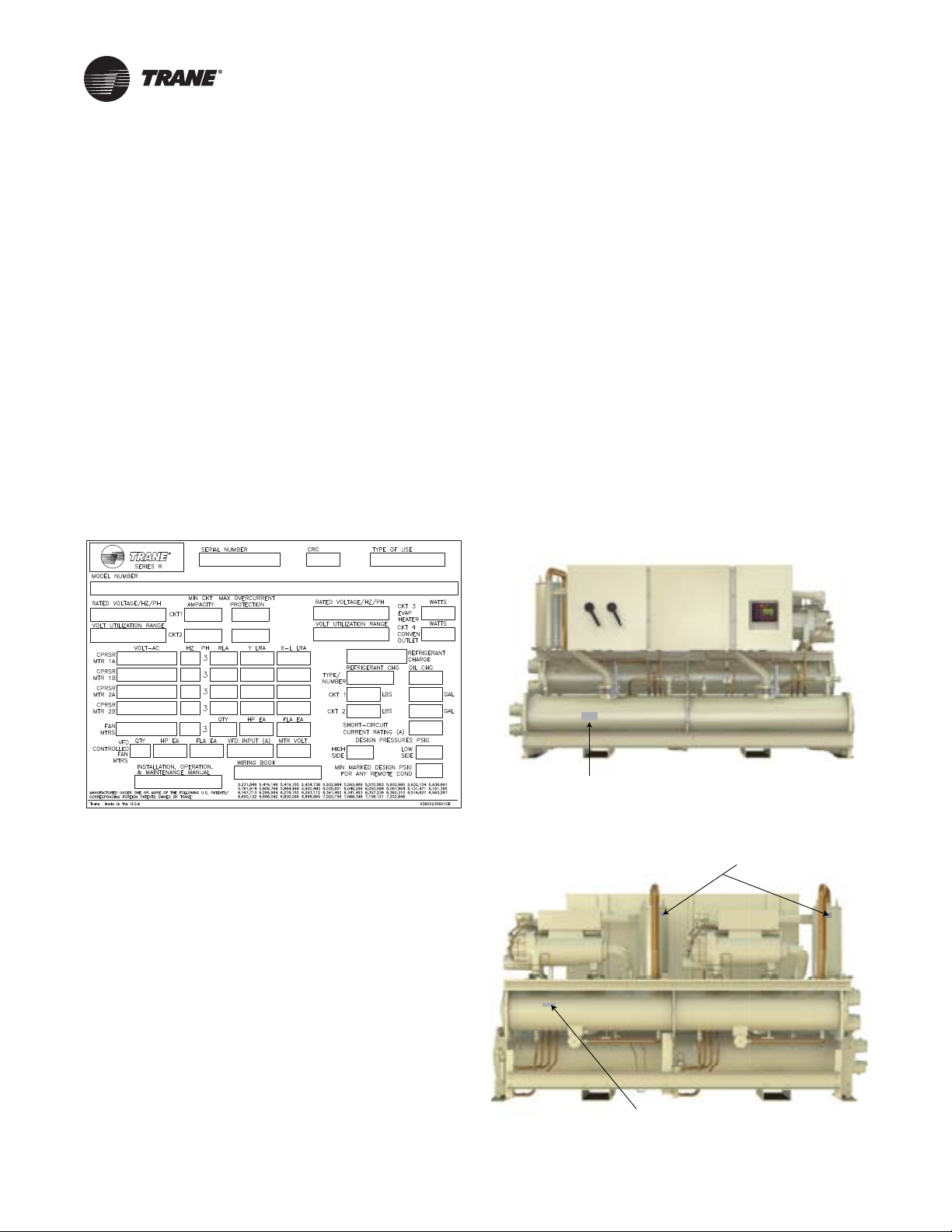
Unit Nameplate
See Figure 1. Unit nameplate includes the following:
• Unit model and size descriptor.
• Unit serial number.
• Identifies unit electrical requirements.
• Lists correct operating charges of R-134a and Oil 48.
• Lists unit test pressures
• Identifies installation, operation and maintenance and
service data literature.
• Lists drawing numbers for unit wiring diagrams.
Figure 1. Unit nameplate
Model Number Coding System
Model numbers for unit and compressors are comprised
of numbers and letter which represent equipment
features.
See “RTWD Model Number,” p. 7and “Compressor Model
Number,” p. 8 for details.
Each position, or group of positions, in a number or letter
is used to represent a feature.For example, from the chart,
we can determine that “F” in digit 8 of unit model number
indicates unit voltage is 460/60/3.
ASME Nameplate
The ASME nameplate is different for the evaporators,
condensers (RTWD only) and oil separators.The
evaporator nameplate is located on the left portion of the
shell.The insulation over the nameplate is intentionally
left unglued, for ease in viewing the nameplate.
The condenser nameplate is on the backside of the
condenser below circuit 2 compressor.
Figure 2. Location of ASME unit nameplate - front
Evaporator ASME Nameplate
%VAPORATOR
Figure 3. Location of ASME unit nameplates - back
Compressor Nameplate
Compressor nameplate includes the following:
Oil Separator
SME Nameplates
/IL3EPARATOR
!3-%NAMEPLATES
• Compressor model number.
• Compressor serial number.
• Compressor electrical characteristics.
• Utilization Range.
• Recommended refrigerant.
#ONDENSER
Condenser
!3-%NAMEPLATES
ASME nameplates (RTWD only)
Condenser ASME Nameplate
(RTWD only)
6 RLC-SVX09H-EN
Page 7

Model Number Descriptions
RTWD Model Number
Digits 1-4— Chiller Model
RTWD= Water Cooled Chiller - Series R
RTUD= Compressor Series R®Chiller
Digits 5-7— Unit Nominal
Tonnage
060 = 60 NominalTons
070 = 70 NominalTons
080 = 80 NominalTons
090 = 90 NominalTons
100 = 100 NominalTons
110 = 110 Nominal Tons
120 = 120 NominalTons
130 = 130 NominalTons
140 = 140 NominalTons
150 = 150 NominalTons
160 = 160 NominalTons
180 = 180 NominalTons
200 = 200 Nominal Tons
220 = 220 NominalTons
250 = 250 NominalTons
Digit 8— Unit Voltage
A = 200/60/3
B = 230/60/3
D = 380/60/3
E = 400/50/3
F = 460/60/3
G = 575/60/3
Digit 9— Manufacturing Plant
2 = Pueblo, USA
Digits 10, 11— Design Sequence
XX = Factory Assigned
Digit 12— UnitType
1 = Standard efficiency/performance
2 = High efficiency/performance
3 = Premium efficiency/performance
Digit 13— Agency Listing
0 = No agency listing
A = UL listed to US and Canadian
safety standards
D = IBC Seismically Rated Unit
E = UL/Canadian and IBC
F = OSHPD Seismically Rated Unit
G = UL/Canadian and OSHPD
Digit 14— Pressure Vessel Code
1 = ASME pressure vessel code
3 = Chinese code-imported pressure
vessel
S = Special
Digit 15— Unit Application
A = Standard condenser
(< 95°F/35°C entering water)
B = High temperature condenser
(>95°F/35°C entering water)
C = Water-to-water heat pump
D = Remote condenser byTrane
E = Remote condenser by others
Digit 16— Pressure ReliefValve
1 = Single relief valve
2 = Dual relief valve with 3-way
isolation valve
Digit 17— Water Connection
®
Type
A = Grooved pipe connection
Digit 18— EvaporatorTubes
A = Internal and External enhanced
Digit 19— Number of
Evaporator Passes
2 = 2-pass evaporator
3 = 3-pass evaporator
Digit 20— Evaporator Water
Side Pressure
A = 150 psi/10.5 bar evaporator
Digit 21— Evaporator
Application
1 = Standard cooling
2 = Low temperature
3 = Ice-making
Digit 22— CondenserTubes
X = Remote condenser
A = Enhanced fin - copper
B = Internally enhanced 90/10 CuNi
Digit 23— Condenser Water
Side Pressure
0 = Remote condenser
1 = 150 psi/10.5 bar condenser water
Digit 24— Compressor Starter
Type
Y = Wye-delta closed transition
X = Across-the-line starter
Digit 25— Incoming Power Line
Connection
1 = Single point power connection
2 = Double point power connection
Digit 26— Power Line
ConnectionType
A = Terminal block
B = Mechanical disconnect switch
D = Circuit breaker
E = High fault rated panel with circuit
Digit 27— Under/Over Voltage
Protection
0 = No under/over voltage
1 = Under/over voltage protection
water pressure
fin
pressure
starter
breaker
protection
Digit 28— Unit Operator
Interface
A = Dyna-View/English
B = Dyna-View/Spanish
C = Dyna-View/Spanish-Mexico
D = Dyna-View/French
E = Dyna-View/German
F = Dyna-View/Dutch
G = Dyna-View/Italian
H = Dyna-View/Japanese
J = Dyna-View/Portuguese-Portugal
K = Dyna-View/Portuguese-Brazil
L = Dyna-View/Korean
M = Dyna-View/Thai
N = Dyna-View/Simplified Chinese
P = Dyna-View/Traditional Chinese
R = Dyna-View/Russian
T = Dyna-View/Polish
U = Dyna-View/Czech
V = Dyna-View/Hungarian
W = Dyna-View/Greek
X = Dyna-View/Romanian
Y = Dyna-View/Swedish
Digit 29— Remote Interface
(Digital Comm)
0 = No remote digital
communication
A = LonTalk/Tracer Summit™
interface
B = Time of day scheduling
4 = Unit Level BACnet
Digit 30— External Water and
Current Limit Setpoint
0 = No external water and current
limit setpoint
A = External water and current limit
setpoint 4-20 mA
B = External water and current limit
setpoint 2-10 Vdc
Digit 31— Ice Making
0 = No ice making
A = Ice making with relay
B = Ice making without relay
Digit 32— Programmable Relays
0 = No programmable relays
A = Programmable relays
Digit 33— Condenser
Refrigerant Pressure Output
Option
0 = No condenser refrigerant output
1 = Condenser water control output
2 = Condenser pressure (%HPC)
output
3 = Differential pressure output
Digit 34— Outdoor AirTemp
Sensor
0 = No outdoor air temp sensor
A = Outdoor air temp sensor - CWR
(low ambient
RLC-SVX09H-EN 7
Page 8

Digit 35— Condenser Leaving
Hot WaterTemp Control
0 = No condenser leaving hot water
temperature control
1 = Condenser leaving hot water
temperature control
Digit 36— Power Meter
0 = No power meter
P = Power meter
Digit 37— Motor Current Analog
Output (%RLA)
0 = No motor current analog output
1 = Motor current analog output
Digit 38— A/C Fan Control
0 = No fan controls (RTWD)
A = Fan control by others
B = Integral fan controls
Digit 39— Low Ambient Fan
ControlType
0 = No low ambient fan control type
(RTWD)
1 = Two speed fan
2 = Variable speed fan with analog
interface
3 = Variable speed fan with PWM
interface
Digit 40— Installation
Accessories
0 = No installation accessories
(shipped with elastomeric pad)
A = Elastomeric (neoprene) isolators
B = Flanged water connection kit
C = Isolators and flanged water
connection kit
Digit 41— Flow Switch
0 = No flow switch
1 = 150 psi NEMA 1; flow switch x 1
2 = 150 psi NEMA 1; flow switch x 2
3 = 150 psi NEMA 4; flow switch x 1
4 = 150 psi NEMA 4; flow switch x 2
7 = Factory installed proof of
evaporator and condenser
8 = Factory installed proof of
evaporator
9 = Factory installed proof of
condenser
Digit 42— 2-Way Water
Regulating Valve
0 = No 2-way water regulating valve
A = 3” 150psi/88.9mm 10.5 bar 115V
B = 3” 150psi/88.9mm 10.5 bar 220V
C = 3” 150psi/114.3mm 10.5bar 115V
D = 3” 150psi/114.3mm 10.5bar 220V
Digit 43— Sound Reduction
Package
0 = No sound reduction package
A = Sound reduction - factory
installed
Digit 44— Insulation
0 = No insulation
1 = Factory insulation, all cold parts
2 = Insulation for high humidity
Digit 45— Factory Charge
0 = Full factory refrigerant charge
(R-134a)
1 = Nitrogen charge
Digit 46— Base Rail Forklifting
0 = No base rail forklifting
B = Base rail forklifting
Digit 47— Label and Literature
Language
B = Spanish
D = English
E = French
G = Chinese - traditional
Digit 48— Special
0 = None
A = Special
Digits 49-55
0 = None (not used)
Digit 56— Shipping Package
0 = No skid (standard)
1 = Skid
2 = Shrink wrap
3 = Skid and shrink wrap
Digits 57-58
x = Factory assigned
Digit 59— PerformanceTest
Options
0 = No performance test
C = 1 point test with report
D = 2 point test with report
E = 3 point test with report
F = 4 point test with report
G = Witness 1 point test with report
H = Witness 2 point test with report
J = Witness 3 point test with report
K = Witness 4 point test with report
Digit 60— Evaporator FluidType
0 = Water
1 = Calcium chloride
2 = Ethylene glycol
3 = Propylene glycol
4 = Methanol
Compressor Model Number
Digits 1-4— Compressor Model
CHHN= Positive displacement,
helical rotary (twin screw)
hermetic compressor
Digits 5-7— Size
0N2= 120 Tons
0N1= 100 Tons
0M2= 85Tons
0M1= 70Tons
0L2 = 60Tons
0L1 = 50Tons
0K2= 40 Tons
0K1= 35 Tons
Digit 8— Unit Voltage
A = 200/60/3
R = 220/50/3
C = 230/60/3
D = 380/60/3
H = 575/60/3
T = 460/60/3 or 400/50/3
Digit 9— Internal Relief
K = 450 psid
Digits 10, 11— Design Sequence
XX = Factory Assigned
Digit 12— Capacity Limit
N = Standard capacity controls
(no capacity limit
Digits 13-15— Motor kW Rating
134 = 134 kW (N2/60Hz)
112 = 112 kW (N2/50Hz)
092 = 092 kW (M2/60Hz)
077 = 077 kW (M2/50Hz)
069 = 069 kW (L2/60Hz)
058 = 058 kW (L2/50Hz)
050 = 050 kW (K2/60Hz)
041 = 041 kW (K2/50Hz)
112 = 112 kW (N1/60Hz)
093 = 093 kW (N1/50Hz)
077 = 077 kW (M1/60Hz)
065 = 065 kW (M1/50Hz)
057 = 057 kW (L1/60Hz)
048 = 048 kW (L1/60Hz)
043 = 043 kW (K1/60Hz)
036 = 036 kW (K1/60Hz)
Digit 16— Volume Ratio
A = High volume ratio
N = Low volume ratio
8 RLC-SVX09H-EN
Page 9

General Information
Unit Description
The RTWD units are helical-rotary type, water-cooled,
liquid chillers, designed for installation indoors.The units
have 2 independent refrigerant circuits, with one
compressor per circuit.The RTWD units are packaged with
an evaporator and condenser.
Note: Each RTWD unit is a completely assembled,
hermetic package that is factory-piped, wired, leak-
tested, dehydrated, charged and tested for proper
control operations prior to shipment.The chilled
water inlet and outlet openings are covered for
shipment.
The RTWD series featuresTrane's exclusive Adaptive
Control logic with CH530 controls. It monitors the control
variables that govern the operation of the chiller unit.
Adaptive Control logic can correct these variables, when
necessary, to optimize operational efficiencies, avoid
chiller shutdown, and keep producing chilled water.
Compressor unloaders are solenoid actuated. Each
refrigerant circuit is provided with filter, sight glass,
electronic expansion valve, and charging valves on the
RTWD.
The evaporator and condenser are manufactured in
accordance with ASME standards.The evaporator is fully
insulated. Both evaporator and condenser are equipped
with water drain and vent connections.
The RTUD units are helical-rotary type compressor
chillers, designed to be most effective when used with the
Levitor II air-cooled condenser.The RTUD unit consists of
an evaporator, two helical rotary compressors (one per
circuit), oil separators, oil coolers, liquid line service
valves, sightglasses, electronic expansion valves and
filter.The discharge line leaving the oil separator and
liquid line entering the filters are capped and brazed. The
unit ships with a full charge of oil and a nitrogen holding
charge.
Accessory/Options Information
Check all the accessories and loose parts which are
shipped with the unit against the original order. Included
in these items will be water vessel drain plugs, rigging
diagrams, electrical diagrams, and service literature,
which are placed inside the control panel and/or starter
panel for shipment. Also check for optional components,
such as flow switches and isolators.
General Data
Table 1. General Data - RTWD - 60 Hz - premium
Compressor L2/M1 M1/M1 M1/M2 M2/M2
Nominal Size 65/70 70/70 70/85 85/85
Evaporator
Water Conn.
Water Storage
Minimum Flow
Water Conn.
Water Storage
Minimum Flow
Condenser
Water Conn.
Water Storage
Minimum Flow
General Unit
Refrig Type R-134a R-134a R-134a R-134a
Refrigerant
Oil Charge
Notes:
1. Data containing information on two circuits is shown as circuit 1/
circuit 2.
2. Flow limits are for water only.
efficiency
Size 150 160 180 200
Quantity 2 2 2 2
2 Pass Arrangement
NPS 6 6 6 6
Size
Maximum
Flow
Size
Maximum
Flow
Size
Maximum
Flow
# Refrig
Circuits
Charge
mm 150 150 150 150
(gal) 27.8 27.8 29.3 31.3
(L) 105.1 105.1 110.9 118.3
(gpm) 174 174 186 202
(L/s) 11.0 11.0 11.8 12.7
(gpm) 639 639 683 739
(L/s) 40.3 40.3 43.1 46.7
3 Pass Arrangement
NPS 4 4 4 4
mm 100 100 100 100
(gal) 27.1 27.1 28.6 30.6
(L) 102.4 102.4 108.3 115.7
(gpm) 116 116 124 134
(L/s) 7.3 7.3 7.8 8.5
(gpm) 426 426 456 493
(L/s) 26.9 26.9 28.7 31.1
NPS 6 6 6 6
mm 150 150 150 150
(gal) 30.0 30.0 32.9 32.9
(L) 113.4 113.4 124.4 124.4
(gpm) 206 206 231 231
(L/s) 13 13 14.6 14.6
(gpm) 755 755 845 845
(L/s) 47.6 47.6 53.3 53.3
2222
174.2/
(lb)
(kg) 79/83 83/83 82/82 81/81
(qts) 10.5/12.4 12.4/12.4 12.4/12.4 12.4/12.4
183.0
(L) 9.9/11.7 11.7/11.7 11.7/11.7 11.7/11.7
183.0/
183.0
180.8/
180.8
178.6/
178.6
RLC-SVX09H-EN 9
Page 10

General Information
Table 2. General Data - RTWD - 60 Hz - standard efficiency
Size 80 90 100 110 120 130 140
Compressor K1/K1 K2/K2 K2/L1 L1/L1 L1/L2 L2/L2 L2/M1
Quantity 2 2 2 2222
Nominal Size 40/40 45/45 45/55 55/55 55/65 65/65 65/70
Evaporator
2 Pass Arrangement
Water Conn. Size NPS 4 4 4 4555
mm 100 100 100 100 125 125 125
Water Storage (gal) 11.2 11.2 12.6 14 15.2 16.2 17.7
(L) 42.2 42.2 47.6 53.0 57.4 61.5 66.8
Minimum Flow (gpm) 77 77 89 101 101 110 122
(L/s) 4.9 4.9 5.6 6.4 6.4 6.9 7.7
Maximum Flow (gpm) 281 281 325 368 368 400 444
(L/s) 17.7 17.7 20.5 23.2 23.2 25.2 28
3 Pass Arrangement
Water Conn. Size NPS 3 3 3 3444
mm 80 80 80 80 100 100 100
Water Storage (gal) 11.2 11.2 12.6 14 15.2 16.2 17.7
(L) 42.2 42.2 47.6 53.0 57.4 61.5 66.8
Minimum Flow (gpm) 52 52 59 67 67 73 81
(L/s) 3.3 3.3 3.8 4.3 4.3 4.6 5.1
Maximum Flow (gpm) 187 187 216 244 244 266 295
(L/s) 11.8 11.8 13.6 15.4 15.4 16.8 18.6
Condenser
Water Conn. Size NPS 5 5 5 5555
mm 125 125 125 125 125 125 125
Water Storage (gal) 12.4 14.2 16.0 16.9 18.5 18.5 20.9
(L) 46.8 53.6 60.4 63.8 70.1 70.1 79.2
Minimum Flow (gpm) 83 99 115 124 135 135 156
(L/s) 5.2 6.3 7.3 7.8 8.5 8.5 9.9
Maximum Flow (gpm) 301 361 421 451 491 491 572
(L/s) 18.9 22.7 26.5 28.4 31.0 31.0 36.0
General Unit
Refrigerant Type R-134a R-134a R-134a R-134a R-134a R-134a R-134a
# Refrig Circuits 2 2 2 2222
Refrigerant Charge (lb) 114.6/114.6 114.6/114.6 112.4/114.6 112.4/112.4 132.3/132.3 130.1/130.1 127.9/132.3
(kg) 52/52 52/52 51/52 51/51 60/60 59/59 58/60
Oil Charge (quarts) 7.2/7.2 7.2/7.2 7.2/10.5 10.5/10.5 10.5/10.5 10.5/10.5 10.5/10.5
(L) 6.8/6.8 6.8/6.8 6.8/9.9 9.9/9.9 9.9/9.9 9.9/9.9 9.9/9.9
Notes:
1. Data containing information on two circuits is shown as circuit 1/circuit 2.
2. Flow limits are for water only.
10 RLC-SVX09H-EN
Page 11

General Information
Table 3. General Data - RTWD - 60 Hz - high efficiency
Size 80 90 100 110 120 130 150 160 180 200 220 250
Compressor K1/K1 K2/K2 K2/L1 L1/L1 L1/L2 L2/L2 L2/M1 M1/M1 M1/M2 M2/M2 M2/N1 N1/N1
Quantity 222222222222
Nominal Size 40/40 45/45 45/55 55/55 55/65 65/65 65/70 70/70 70/85 85/85 85/100 100/100
Evaporator
2 Pass Arrangement
Water Conn.
Water Storage (gal) 9.8 11.9 12.8 15.3 16.4 17.3 19.2 20.3 22.3 24.2 28.6 31.8
Minimum Flow (gpm) 72 92 100 112 123 130 141 151 170 186 211 240
Maximum Flow (gpm) 263 336 364 409 448 476 515 555 622 683 773 879
Water Conn.
Water Storage (gal) 9.8 11.9 12.8 15.3 16.4 17.3 18.8 20.0 22.0 23.8 27.9 31.0
Minimum Flow (gpm) 48 61 67 75 82 87 94 101 113 124 141 160
Maximum Flow (gpm) 175 223 242 271 298 316
Condenser
Water Conn.
Water Storage (gal) 11.9 12.7 14.9 16.6 17.2 18.0 21.6 22.9 24.6 26.2 31.1 39.2
Minimum Flow (gpm) 87 95 117 130 136 145 159 173 189 206 244 325
Maximum Flow (gpm) 317 347 427 473 498 528 584 634 695 755 896 1193
General Unit
Refrigerant Type R-134a R-134a R-134a R-134a R-134a R-134a R-134a R-134a R-134a R-134a R-134a R-134a
# Refrig Circuits 222222222222
Refrigerant
Charge
Oil Charge (qt) 7.2/7.2 7.2/7.2 7.2/10.5
Notes:
1. Data containing information on two circuits is shown as circuit 1/circuit 2.
2. 2. Flow limits are for water only.
NPS445555555566
Size
mm 100 100 100 125 125 125 125 125 125 125 150 150
(L) 37.0 45.2 48.3 57.9 62.3 65.4 72.6 77.0 84.5 91. 108.3 120.3
(L/s) 4.6 5.8 6.3 7.1 7.8 8.2 8.9 9.5 10.7 11.8 13.3 15.1
(L/s) 16.6 21.2 22.9 25.8 28.2 30.0 32.5 35.0 39.2 43.1 48.8 55.5
3 Pass Arrangement
NPS334444444444
Size
mm 80 80 80 100 100 100 100 100 100 100 100 100
(L) 37.0 45.2 48.3 57.9 62.3 65.4 71.2 75.6 83.2 90.1 105.5 117.5
(L/s) 3.1 3.9 4.2 4.7 5.2 5.5 5.9 6.4 7.1 7.8 8.9 10.1
344 370 415 456 515 586
(L/s) 11.0 14.1 15.2 17.1 18.8 19.9
NPS555555666666
Size
mm 125 125 125 125 125 125 150 150 150 150 150 150
(L) 45.1 48.1 56.3 62.7 65.2 68.3 81.7 86.8 93.0 99.2 117.8 148.3
(L/s) 5.5 6.0 7.4 8.2 8.6 9.1 10.1 10.9 12.0 13.0 15.4 20.5
(L/s) 20.0 21.9 26.9 29.8 31.4 33.3 36.8 40.0 43.8 47.6 56.5 75.3
(lb)
(kg) 45/45 44/44 56/57 56/56 55/55 54/54 61/65 64/64 63/63 62/62 81/84 82/82
99.2/
99.2
(L) 6.8/6.8 6.8/6.8 6.8/9.9 9.9/9.9 9.9/9.9 9.9/9.9 9.9/11.7
97/97
123.5/
125.7
123.5/
123.5
10.5/
10.5
121.3/
121.3
10.5/
10.5
119/
119
10.5/
10.5
21.7 23.3 26.2 28.7 32.5 37.0
134.5/
143.3
10.5/
12.4
141.1/
141.1
12.4/
12.4
11.7/
11.7
138.9/
138.9
12.4/
12.4
11.7/
11.7
136.7/
136.7
12.4/
12.4
11.7/
11.7
178.6/
185.2
12.4/
12.4
11.7/
11.7
180.8/
180.8
12.4/
12.4
11.7/
11.7
RLC-SVX09H-EN 11
Page 12

General Information
Table 4. General Data – RTUD – 60 Hz
Size 80 90 100 110 120 130 150 160 180 200 220 250
Compressor K1/K1 K2/K2 K2/L1 L1/L1 L1/L2 L2/L2 L2/M1 M1/M1 M1/M2 M2/M2 M2/N1 N1/N1
Quantity 222222222222
Nominal Size 40/40 45/45 45/55 55/55 55/65 65/65 65/70 70/70 70/85 85/85 85/100 100/100
Evaporator
2 Pass Arrangement
Water Conn.
Water Storage (gal) 9.8 10.6 12.0 14.0 15.3 15.3 16.5 19.2 19.2 20.3 22.3 24.2
Minimum Flow (gpm) 77 79 91 99 111 111 122 140 140 151 169 186
Maximum Flow (gpm) 281 291 335 363 408 408 447 514 514 553 620 681
Water Conn.
Water Storage (gal) 9.5 10.3 11.6 13.7 15.1 15.1 16.1 18.8 18.8 20.0 22.0 23.8
Minimum Flow (gpm) 51 53 61 66 74 74 81 94 94 100 112 124
Maximum Flow (gpm) 187 194 224 242 272 272 298 343 343 368 413 454
General Unit
Refrigerant Type R-134a R-134a R-134a R-134a R-134a R-134a R-134a R-134a R-134a R-134a R-134a R-134a
# Refrig Circuits 222222222222
Refrigerant
Charge
Oil Charge (qt) 7.2/7.2 7.2/7.2 7.2/10.5
Discharge
Connection
Diameter
Connection
Diameter
Notes:
1. Data containing information on two circuits is shown as circuit 1/circuit 2.
2. 2. Flow limits are for water only.
NPS444555555555
Size
mm 100 100 100 125 125 125 125 125 125 125 125 125
(L) 37.1 40.2 45.3 53.0 58.0 58.0 62.4 72.6 72.6 77.0 84.5 91.5
(L/s) 4.9 5.0 5.7 6.2 7.0 7.0 7.7 8.8 8.8 9.5 10.7 11.7
(L/s) 17.7 21.2 23.0 25.8 28.3 30.0 28.2 32.4 32.4 34.9 39.1 43.0
3 Pass Arrangement
NPS333444444444
Size
mm 80 80 80 100 100 100 100 100 100 100 100 100
(L) 36.0 39.0 44.0 52.0 57.0 57.0 61.0 71.2 71.2 75.6 83.2 90.1
(L/s) 3.2 3.3 3.8 4.2 4.7 4.7 5.1 5.9 5.9 6.3 7.1 7.8
(L/s) 11.8 12.2 14.1 15.3 17.2 17.2 18.8 21.6 21.6 23.2 26.1 28.6
(lb) 50/50 49/49 47/47 65/65 64/64 64/64 62/62 66/66 66/66 66/66 63/63 61/61
(kg)
(inch) 2.1 2.1 2.1 2.6 2.6 2.6 2.6 3.1 3.1 3.1 3.1 3.1
Liquid
(inch) 1.1 1.1 1.1 1.4 1.4 1.4 1.4 1.4 1.4 1.4 1.4 1.6
22.7/
22.7
(L) 6.8/6.8 6.8/6.8 6.8/9.9 9.9/9.9 9.9/9.9 9.9/9.9 9.9/9.9 9.9/9.9 9.9/11.7
22.2/
22.2
21.3/
21.3
29.5/
29.5
10.5/
10.5
29.0/
29.0
10.5/
10.5
29.0/
29.0
10.5/
10.5
28.1/
28.1
10.5/
10.5
29.9/
29.9
10.5/
10.5
29.9/
29.9
10.5/
12.4
29.9/
29.9
12.4/
12.4
11.7/
11.7
28.6/
28.6
12.4/
12.4
11.7/
11.7
27.7/
27.7
12.4/
12.4
11.7/
11.7
12 RLC-SVX09H-EN
Page 13

General Information
Table 5. General Data – Condenser byTrane – 60 Hz
Size 80 90 100 110 120 130 150 160 180 200 220 250
Condenser
Condenser
Quantity
Fins/Inch 12 10 10 12 8 10 8/12 12/12 12/8 8/8 8/10 10/10
Coil Length (in) 162 216 216 216 270 270 162/162 162/162 162/216 216/216 216/216 216/216
(mm) 4115 5486 5486 5486 6858 6858
Coil Width (in) 85 85 85 85 85 85 85/85 85/85 85/85 85/85 85/85 85/85
(mm) 2159 2159 2159 2159 2159 2159
Number of Rows 3 3 4 4 4 4 3/3 3/3 3/3 3/3 3/4 4/4
Condenser Fans
Fan Quantity 6 8 8 8 10 10 6/6 6/6 6/8 8/8 8/8 8/8
Diameter (in) 30 30 30 30 30 30 30 30 30 30 30 30
(mm) 762 762 762 762 762 762 762 762 762 762 762 762
Nominal RPM (rpm) 850 850 850 850 850 850 850 850 850 850 850 850
Air Flow (cfm) 56,646 78,280 72,248 69,280 94,490 90,310
Tip Speed (fpm) 6676 6676 6676 6676 6676 6676 6676 6676 6676 6676 6676 6676
Motor HP (hp) 1.5 1.5 1.5 1.5 1.5 1.5 1.5 1.5 1.5 1.5 1.5 1.5
General
Recommended
Refrigerant
Charge¹
Discharge/Liquid
Connection
Diameters
Notes:
1. Data containing information on two condensers is shown as cond 1/cond 2.
2. Data containing information on two circuits is shown as circuit 1/circuit 2.
3. Condenser is not factory charged, the refrigerant must be purchased and charged in
the field.
(lbs) 55/55 92/92 97/97 97/97 98/98 122/122 109/109 109/109 109/146 146/146 146/195 195/195
(kg)
(in) 2.1 2.1 2.1 2.1 2.1 2.1 2.125 2.125 2.125 2.125 2.125 2.125
(mm) 54 54 54 54 54 54 54 54 54 54 54 54
111111222222
24.9/
24.9
41.7/
41.7
44.0/
44.0
44.0/
44.0
44.5/
44.5
55.3/
55.3
4115/
4115
2159/
2159
60,954/
56,646
49.4/
49.4
4115/
4115
2159/
2159
56,646/
56,646
49.4/
49.4
4115/
5486
2159/
2159
56,646/
81,272
49.4/
66.2
5486/
5486
2159/
2159
81,272/
81,272
66.2/
66.2
5486/
5486
2159/
2159
81,272/
72,248
66.2/
88.5
72,248/
72,248
5486/
5486
2159/
2159
88.5/
88.5
RLC-SVX09H-EN 13
Page 14

General Information
Table 6. General Data - RTWD 50 Hz - standard efficiency
Size 70 80 90 100 110 120 130 140 150
Compressor K2/K2 K2/L1 L1/L1 L1/L2 L2/L2 L2/M1 M1/M1 M1/M2 M2/M2
Quantity 2 2 2 222222
Nominal Size 45/45 45/55 55/55 55/65 65/65 65/70 70/70 70/85 85/85
Evaporator
2 Pass Arrangement
Water Conn. Size NPS 4 4 4 445555
mm 100 100 100 100 100 125 125 125 125
Water Storage (gal) 11.2 12.6 14.0 14.0 14.0 16.2 17.7 17.7 19.1
(L) 42.2 47.6 53.0 53.0 53.0 61.5 66.8 66.8 72.2
Minimum Flow (gpm) 77 89 101 101 101 110 122 122 133
(L/s) 4.9 5.6 6.3 6.3 6.3 6.9 7.7 7.7 8.4
Maximum Flow (gpm) 281 324 368 368 368 400 444 444 487
(L/s) 17.7 20.5 23.2 23.2 23.2 25.2 28.0 28.0 30.7
3 Pass Arrangement
Water Conn. Size NPS 3 3 3 334444
mm 80 80 80 80 80 100 100 100 100
Water Storage (gal) 11.2 12.6 14.0 14.0 14.0 16.2 17.7 17.7 19.1
(L) 42.2 47.6 53.0 53.0 53.0 61.5 66.8 66.8 72.2
Minimum Flow (gpm) 52 59 67 67 67 73 81 81 89
(L/s) 3.3 3.8 4.3 4.3 4.3 4.6 5.1 5.1 5.6
Maximum Flow (gpm) 187 216 244 244 244 266 295 295 324
(L/s) 11.8 13.6 15.4 15.4 15.4 16.8 18.6 18.6 20.4
Condenser
Water Conn. Size NPS 5 5 5 555555
mm 125 125 125 125 125 125 125 125 125
Water Storage (gal) 12.4 14.2 16.0 16.9 16.9 18.5 20.9 20.9 22.4
(L) 46.8 53.6 60.4 63.8 63.8 70.1 79.2 79.2 84.8
Minimum Flow (gpm) 83 99 115 124 124 135 156 156 170
(L/s) 5.2 6.3 7.3 7.8 7.8 8.5 9.9 9.9 10.8
Maximum Flow (gpm) 301 361 421 451 451 491 571 571 622
(L/s) 18.9 22.7 26.5 28.4 28.4 31.0 36.0 36.0 39.2
General Unit
Refrigerant Type R134a R134a R134a R134a R134a R134a R134a R134a R134a
# Refrig Circuits 2 2 2 222222
Refrigerant Charge (lb)
(kg) 52/52 51/51 50/50 50/51 51/51 59/59 58/58 58/60 59/59
Oil Charge (quarts) 7.2/7.2 7.2/7.2 7.2/7.2 7.2/10.5 10.5/10.5 10.5/10.5 10.5/10.5 10.5/10.5 10.5/10.5
(L) 6.8/6.8 6.8/6.8 6.8/6.8 6.8/9.9 9.9/9.9 9.9/9.9 9.9/9.9 9.9/9.9 9.9/9.9
Notes:
1. Data containing information on two circuits is shown as circuit 1/circuit 2.
2. Flow limits are for water only.
114.6/
114.6
112.4/
112.4
110.2/
110.2
110.2/
112.4
112.4/
112.4
130.1/
130.1
127.9/
127.9
127.9/
132.3
130.1/
130.1
14 RLC-SVX09H-EN
Page 15

General Information
Table 7. General Data - RTWD 50 Hz - high efficiency
Size 60 70 80 90 100 110 120 130 140 160 180 200 220 250
Compressor K1/K1 K2/K2 K2/L1 L1/L1 L1/L2 L2/L2 L2/M1 M1/M1 M1/M2 M2/M2 M2/N1 N1/N1 N1/N2 N2/N2
Quantity 22222222222222
Nominal Size 40/40 45/45 45/55 55/55 55/65 65/65 65/70 70/70 70/85 85/85 85/100
Evaporator
2 Pass Arrangement
NPS44455555555666
Water
Conn. Size
Storage
Minimum
Maximum
Conn. Size
Storage
Minimum
Maximum
Condenser
Conn. Size
Storage
Minimum
Maximum
General Unit
Refrig Type R-134a R-134a R-134a R-134a R-134a R-134a R134a R-134a R-134a R-134a R134a R-134a R-134a R-134a
# Refrig
Circuits
Refrigerant
Charge
Oil Charge
Notes:
1. Data containing information on two circuits is shown as circuit 1/circuit 2.
2. Flow limits are for water only.
mm 100 100 100 125 125 125 125 125 125 125 125 150 150 150
(gal) 9.8 10.6 11.9 15.3 15.3 16.4 17.3 19.2 20.3 22.3 24.2 28.6 29.9 31.8
Water
(L) 37.0 40.2 45.2 57.9 57.9 62.3 65.4 72.6 77.0 84.5 91.5 108.3 113.3 120.3
(gpm) 72 80 92 112 112 123 130 141 151 170 186 211 223 240
Flow
(L/s) 4.6 5.1 5.8 7.1 7.1 7.8 8.2 8.9 9.5 10.7 11.8 13.3 14.1 15.1
(gpm) 263 291 336 408 408 448 476 515 555 622 683 773 818 879
Flow
(L/s) 16.6 18.3 21.2 25.8 25.8 28.2 30.0 32.5 35.0 39.2 43.1 48.8 51.6 55.5
3 Pass Arrangement
NPS33344444444444
Water
mm 80 80 80 100 100 100 100 100 100 100 100 100 100 100
(gal) 9.8 10.6 11.9 15.3 15.3 16.4 17.3 18.8 20.0 22.0 23.8 27.9 29.2 31.0
Water
(L) 37.0 40.2 45.2 57.9 57.9 62.3 65.4 71.2 75.6 83.2 90.1 105.5 110.5 117.5
(gpm) 48 53 61 75 75 82 86 94 101 113 124 141 149 160
Flow
(L/s) 3.1 3.4 3.9 4.7 4.7 5.2 5.5 5.9 6.4 7.1 7.8 8.9 9.4 10.1
(gpm) 175 193 223 271 271 298 316 344 370 415 456 515 545 586
Flow
(L/s) 11.0 12.2 14.1 17.1 17.1 18.8 19.9 21.7 23.3 26.2 28.7 32.5 34.4 37.0
NPS55555556666666
Water
mm 125 125 125 125 125 125 125 150 150 150 150 150 150 150
(gal) 11.9 11.9 13.8 15.3 16.6 16.6 18.0 21.6 22.9 24.6 26.2 31.1 31.1 35.2
Water
(L) 45.1 45.1 52.2 58.1 62.7 62.7 68.3 81.7 86.8 93.0 99.2 117.8 117.8 133.3
(gpm) 87 87 106 117 130 130 145 159 173 189 206 244 244 286
Flow
(L/s) 5.5 5.5 6.7 7.4 8.2 8.2 9.1 10.0 10.9 11.9 13.0 15.4 15.4 18.0
(gpm) 317 317 387 427 473 473 528 584 634 695 755 896 896 1047
Flow
(L/s) 20.0 20.0 24.4 26.9 29.8 29.8 33.3 36.8 40.0 43.8 47.6 56.5 56.5 66.1
22222222222222
99.2/
(lb)
99.2
(kg) 45/45 45/45 44/44 55/55 55/56 55/55 54/54 61/61 60/62 61/61 60/62 81/81 80/83 82/82
7.2/
(qts)
6.8/
(L)
7.2
6.8
99.2/
99.2
7.2/
7.2
6.8/
6.8
97/97
7.2/
7.2
6.8/
6.8
121.3/
121.3
7.2/
7.2
6.8/
6.8
121.3/
123.5
7.2/
10.5
6.8/
9.9
121.3/
121.3
10.5/
10.5
9.9/
9.9
119/
119
10.5/
10.5
9.9/
9.9
134.5/
134.5
10.5/
10.5
9.9/
9.9
132.3/
136.7
10.5/
10.5
9.9/
9.9
134.5/
134.5
10.5/
10.5
9.9/
9.9
132.3/
136.7
10.5/
12.4
9.9/
11.7
100/
100
178.6/
178.6
12.4/
12.4
11.7/
11.7
100/
120
176.4/
183.0
12.4/
12.4
11.7/
11.7
120/
120
180.8/
180.8
12.4/
12.4
11.7/
11.7
RLC-SVX09H-EN 15
Page 16

General Information
Table 8. General Data - RTWD 50 Hz - premium efficiency
Size 160 180 200
Compressor M2/M2 M2/N1 N1/N1
Quantity 2 2 2
Nominal Size 85/85 85/100 100/100
Evaporator
2 Pass Arrangement
Water Conn. Size NPS 6 6 6
mm 150 150 150
Water Storage (gal) 29.3 31.3 31.8
(L) 110.9 118.3 120.3
Minimum Flow (gpm) 186 202 240
(L/s) 11.8 12.7 15.1
Maximum Flow (gpm) 683 739 879
(L/s) 43.1 46.7 55.5
3 Pass Arrangement
Water Conn. Size NPS 4 4 4
mm 100 100 100
Water Storage (gal) 28.6 30.6 31.0
(L) 108.3 115.7 117.5
Minimum Flow (gpm) 124 134 160
(L/s) 7.8 8.5 10.1
Maximum Flow (gpm) 456 493 586
(L/s) 28.7 31.1 37.0
Condenser
Water Conn. Size NPS 6 6 6
mm 150 150 150
Water Storage (gal) 30.0 34.5 39.2
(L) 113.4 130.6 148.3
Minimum Flow (gpm) 206 244 325
(L/s) 13.0 15.4 20.5
Maximum Flow (gpm) 755 896 1193
(L/s) 47.6 56.5 75.3
General Unit
Refrigerant Type R-134a R-134a R-134a
# Refrig Circuits 2 2 2
Refrigerant Charge (lb) 176.4/176.4 176.6/178.6 176.4/174.2
(kg) 80/80 79/81 80/79
Oil Charge (qts) 10.5/10.5 10.5/12.4 12.4/12.4
(L) 9.9/9.9 9.9/11.7 11.7/11.7
1. Data containing information on two circuits is shown as circuit 1/circuit 2.
2. Flow limits are for water only.
16 RLC-SVX09H-EN
Page 17

Pre-Installation
Inspection Checklist
When the unit is delivered, verify that it is the correct unit
and that it is properly equipped. Compare the information
which appears on the unit nameplate with the ordering
and submittal information. See “Model Number
Descriptions,” p. 7.
Inspect all exteriorcomponents for visibledamage. Report
any apparent damage or material shortage to the carrier
and make a “unit damage” notation on the carrier's
delivery receipt. Specify the extent and type of damage
found and notify the appropriateTrane Sales Office.
Important: Do not proceed with installation of a
damaged unit without sales office approval.
To protect against loss due to damage incurred in transit,
complete the following checklist upon receipt of the unit.
• Inspect the individual pieces of the shipment before
accepting the unit. Check for obvious damage to the
unit or packing material.
• Inspect the unit for concealed damage as soon as
possible after delivery and before it is stored.
Concealed damage must be reported within 15 days.
• If concealed damage is discovered, stop unpacking the
shipment. Do not remove damaged material from the
receiving location.Take photos of the damage, if
possible.The owner must provide reasonable
evidence that the damage did not occur after delivery.
• Notify the carrier's terminal of the damage
immediately, by phone and by mail. Request an
immediate, joint inspection of the damage with the
carrier and the consignee.
• Notify theTrane sales representative and arrange for
repair. Do not repair the unit, however, until damage is
inspected by the carrier's representative.
Unit Storage
If the chiller is to be stored for more than one month prior
to installation, observe the following precautions:
• Do not remove the protective coverings from the
electrical panel.
• Store the chiller in a dry, vibration-free, secure area.
• At least every three months, attach a gauge and
manually check the pressure in the refrigerant circuit.
If the refrigerant pressure is below 71 psigat 70 F (or 46
psig at 50 F), call a qualified service organization and
the appropriateTrane sales office.
Note: Pressure will be approximately 20 psig if shipped
with the optional nitrogen charge.
Installation requirements and Contractor responsibilities
A list of the contractor responsibilities typically associated
with the unit installation process is provided in Table 9.
Note: Unit Start-up must be completed by a qualified
Trane service technician.
Table 9. Installation requirements
Type of
Rqmt
Foundation • Meet foundation
Rigging • Safety chains
Isolation • Isolation
Electrical • Circuit
Water
piping
Relief • Single relief
Insulation • Insulation
Water
Piping
Connection
Componen
ts
Other
Materials
Trane Supplied
breakers or
fusible
disconnects
(optional)
• Unit mounted
starter
• Flow
switches
(optional)
valve
• Dual relief
valves (opt)
• High humidity
insulation (opt)
• Grooved pipe
• Grooved pipe
to flanged
connection
(opt)
Field
Installed
pads or
neoprene
isolators
(opt)
• Flow
switches
(may be
field
supplied)
• Water
regulating
valve
(optional)
• Flow
switches
(may be
field
supplied)
• Water
regulating
valve
(optional)
Field Supplied
Field InstalledTrane Installed
requirements
Clevis connectors
Lifting beam
• Isolation pads or neoprene
isolators (optional)
• Circuit breakers or fusible
disconnects (opt)
• Electrical connections to unit
mounted starter (opt)
• Electrical connections to
remote mounted starter
(opt)
• Wiring sizes per submittal
and NEC
• Terminal lugs
• Ground connection(s)
• BAS wiring (opt)
• Control voltage wiring
• Chilled water pump
contactor and wiring
including interlock
• Condenser water pump
contactor and wiring
including interlock
• Option relays and wiring
• Taps for thermometers and
gauges
• Thermometers
• Strainers (as required)
• Water flow pressure gauges
• Isolation and balancing
valves in water piping
• Vents and drain on waterbox
valves
• Pressure relief valves (for
waterboxes as required)
• Vent line and flexible
connector and vent line from
relief valve to atmosphere
• Insulation
• R-134a refrigerant (1 lb.
max per machine as needed)
• Dry nitrogen (20 psig max
per machine as needed)
RLC-SVX09H-EN 17
Page 18
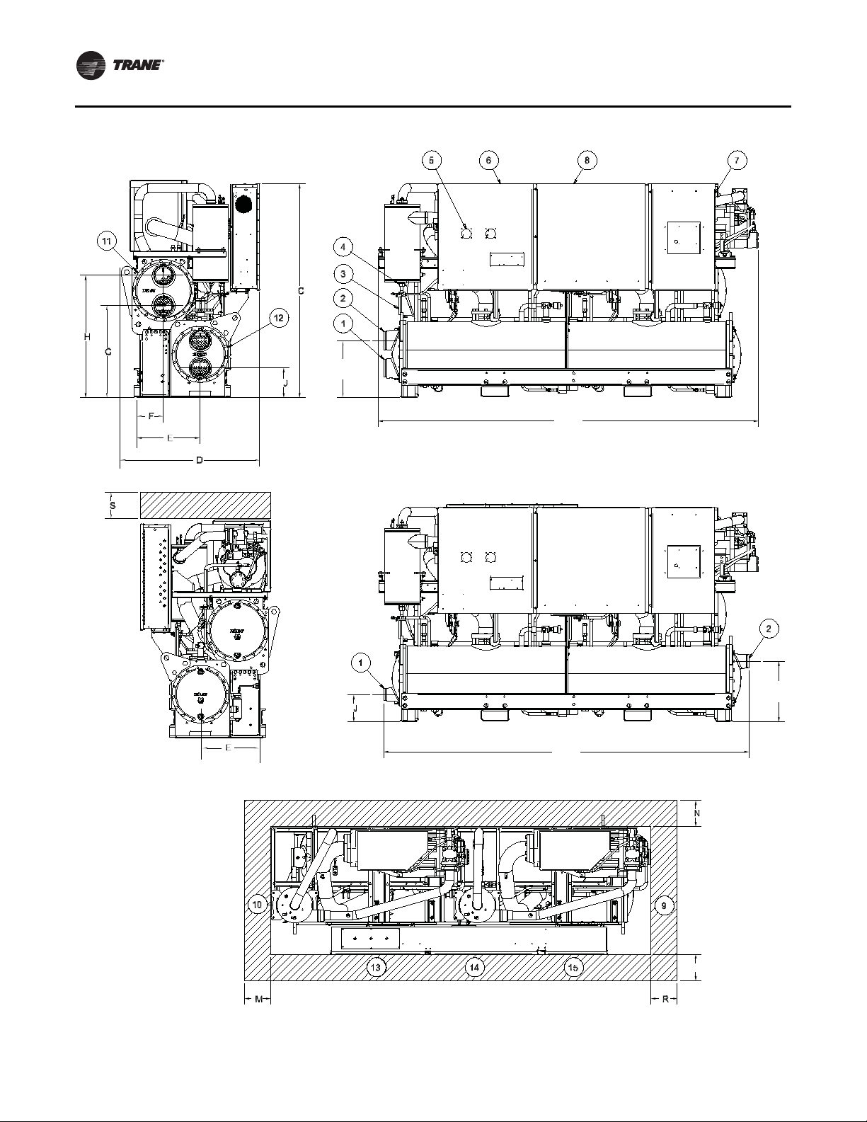
Unit Dimensions/Weights
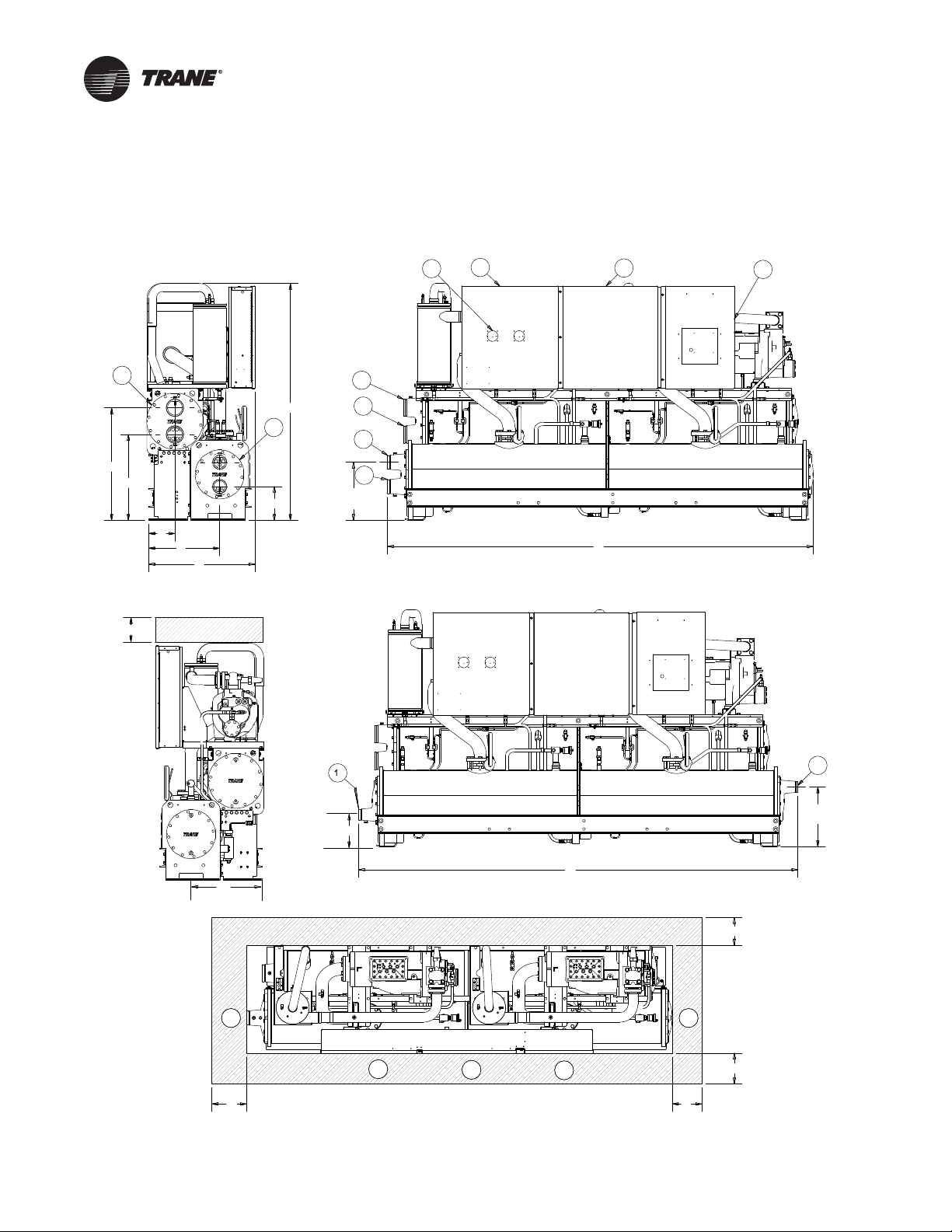
Service Clearances and Dimension
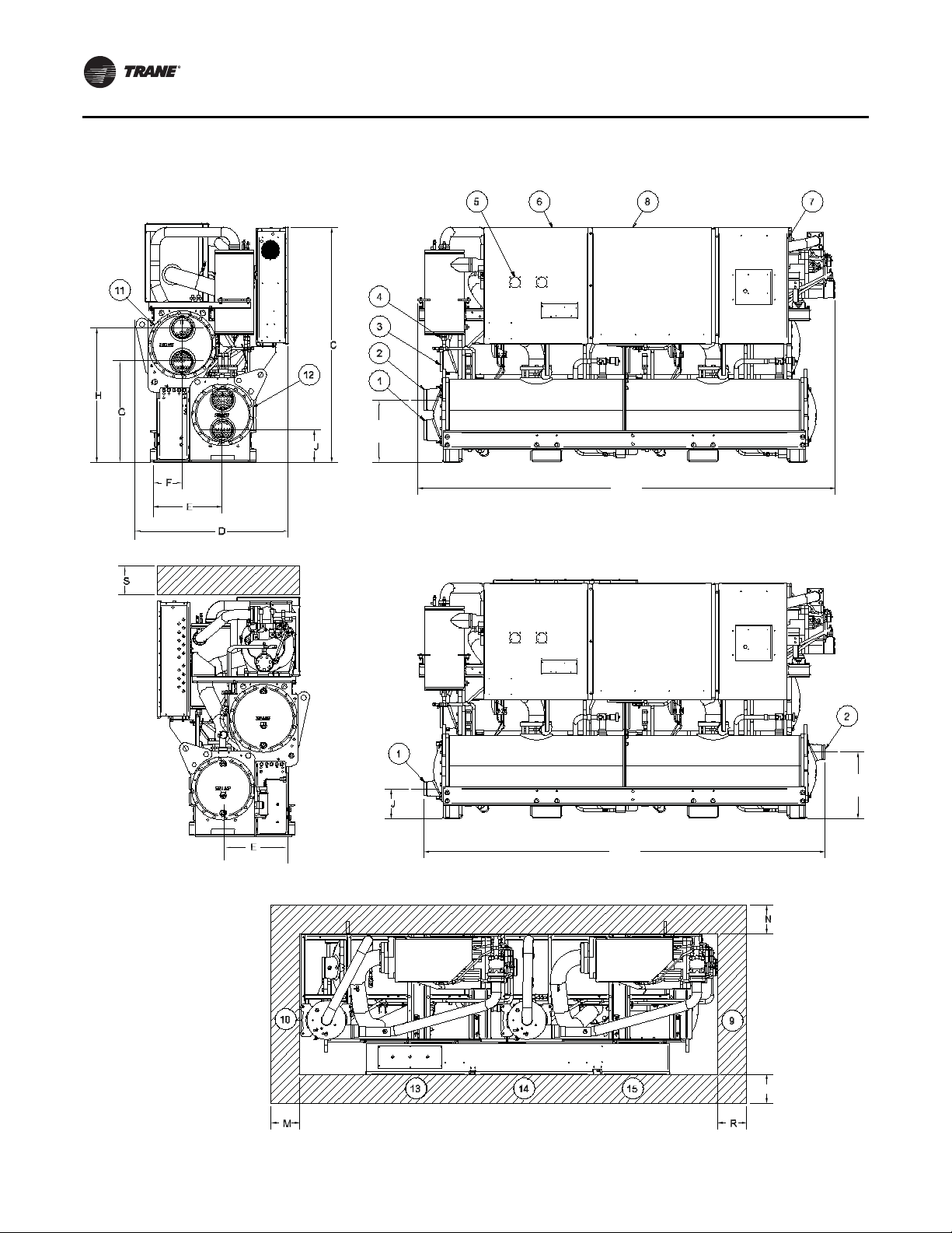
Figure 4. RTWD/RTUD – 60 Hz dimensions – 80-140 ton
5
11
C
12
H
G
J
F
E
D
4
3
2
1
K
(2 pass evap)
2 pass evap
6
8
( 2 pass evap )
A
7
3 pass evap
S
2
L
(3 pass evap)
E
( 3 pass evap )
10
M
1
J
( 3 pass evap )
B
N
9
13
14
15
R
N
18 RLC-SVX09H-EN
Page 19
Unit Dimensions/Weights
Table 10. RTWD/RTUD – 60 Hz dimensions – 80-140 ton
Standard Efficiency RTWD/RTUD - High Efficiency
A (2 pass evap)
B (3 pass evap)
C
D
E
F
G
H
J (2 pass evap)
J (3 pass evap)
K (2 pass evap)
L (3 pass evap)
M
N*
R
S
80,90
inch (mm)
138.2 (3510) 138.2 (3510) 138.8 (3525) 126.4 (3210) 126.9 (3225)
142.6 (3621) 142.6 (3621) 142.6 (3621) 130.8 (3321) 130.7 (3320)
75.9 (1929) 76.9 (1955) 76.9 (1955) 76.1 (1933) 76.9 (1955)
34.3 (871) 34.3 (871) 34.8 (884) 35.1 (890) 35.1 (890)
23.6 (600) 23.6 (600) 23.6 (600) 23.6 (600) 23.6 (600)
9.1 (231) 9.1 (231) 9.1 (231) 9.1 (231) 9.1 (231)
27.9 (709) 27.9 (709) 27.9 (709) 27.9 (709) 27.9 (709)
36.6 (929) 36.6 (929) 36.6 (929) 36.6 (929) 36.6 (929)
11.0 (280) 11.0 (280) 10.6 (268) 10.8 (273) 11.8 (299)
10.4 (265) 10.4 (265) 10.1 (256) 10.2 (258) 11.3 (287)
18.9 (479) 18.9 (479) 19.2 (487) 18.6 (472) 20.4 (519)
19.5 (495) 19.5 (495) 19.5 (496) 19.2 (488) 19.2 (487)
36 (914) 36 (914) 36 (914) 36 (914) 36 (914)
36 (914)* 36 (914)* 36 (914)* 36 (914)* 36 (914)*
127 (3226) 127 (3226) 127 (3226) 115 (2921) 115 (2921)
36 (914) 36 (914) 36 (914) 36 (914) 36 (914)
100,110
inch (mm)
120,130,140
inch (mm)
80,90
inch (mm)
100,110,120,130
inch (mm)
Reference
1
2
3
4
5
6
7
8
9
10
11
12
13
14
15
*
**
Evaporator Water Inlet
Evaporator Water Outlet
Condenser Water Inlet (RTWD only)
Condenser Water Outlet (RTWD only)
Power Disconnect
Power Wire
Control Wire
Control Panel
Condenser Return Waterbox End (RTWD only) - minimum clearance (for tube removal)
Condenser Supply Waterbox End (RTWD only) - minimum clearance (for maintenance)
Condenser (RTWD only)
Evaporator
Panel Power Section - door swing 31.3 inch (796.9 mm)
Panel Power Section - door swing 31.1 inch (790.1 mm)
Panel Control Section - door swing 22.4 inch (568.14 mm)
42 inch (1067 mm) clearance required to other ground parts, two units with panels facing each other or other live parts
require a clearance of 48 inch (1220 mm)
Sound attenuator may increase the footprint - submittal should be used.
RLC-SVX09H-EN 19
Page 20
Unit Dimensions/Weights
Figure 5. RTWD/RTUD – 60 Hz dimensions – 150-250 tons
K
(2 pass evap)
( 2 pass evap )
A
2 pass evap
(3 pass evap)
( 3 pass evap )
B
3 pass evap
L
(3 pass evap)
P
20 RLC-SVX09H-EN
Page 21
Unit Dimensions/Weights
Table 11. RTWD/RTUD – 60 Hz dimensions – 150-250 tons
A (2 pass evap)
B (3 pass evap)
C
D
E
F
G
H
J (2 pass evap)
J (3 pass evap)
K (2 pass evap)
L (3 pass evap)
M
N
P*
R
S
RTWD
High Efficiency Prem Efficiency
150-200
inch (mm)
132.3 (3360) 136.1 (3456) 147.9 (3755) 126.9 (3225) 132.3 (3360) 132.3 (3360)
132.8 (3371) 136.1 (3456) 150.9 (3831) 130.8 (3321) 132.8 (3371) 132.9 (3376)
75.6 (1920) 76.9 (1955) 76.8 (1950) 76.9 (1955) 75.6 (1920) 76.7 (1949)
47.3 (1202) 47.8 (1213) 47.3 (1202) 37.9 (962) 47.4 (1203) 47.4 (1203)
24.6 (624) 24.8 (630) 24.6 (624) 23.5 (599) 24.5 (624) 24.6 (624)
11.1 (282) 11.2 (295) 11.1 (282) - - -
32.7 (830) 33.1 (840) 33.8 (860) - - -
42.4 (1078) 43.9 (1115) 43.6 (1108) - - -
10.1 (256) 10.6 (270) 10.6 (270) 10.2/259 10.1 (256) 11.3 (263)
9.5 (241) 9.7 (247) 9.7 (247) 9.8/247 9.5 (241) 8.8 (223)
19.3 (490) 20.6 (524) 20.6 (524) 18.9/479 19.3 (490) 19.9 (483)
19.9 (505) 21.6 (549) 21.6 (549) 19.8/501 19.9 (505) 20.7 (526)
36.0 (914) 36.0 (914) 36.0 (914) 36.0 (914) 36.0 (914) 36.0 (914)
36.0 (914) 36.0 (914) 36.0 (914) 36.0 (914) 36.0 (914) 36.0 (914)
40 (1016)* 40 (1016)* 40 (1016)* 40 (1016)* 40 (1016)* 40 (1016)*
114.8 (2916) 114.8 (2916) 134.5 (3416) 114.8 (2916) 114.8 (2916) 114.8 (2916)
36.0 (914) 36.0 (914) 36.0 (914) 36.0 (914) 36.0 (914) 36.0 (914)
220, 250
inch (mm)
150-200
inch (mm)
150
inch (mm)
RTUD
160-200
inch (mm)
220,250
inch (mm)
Reference
1
2
3
4
5
6
7
8
9
10
11
12
13
14
15
*
**
Evaporator Water Inlet
Evaporator Water Outlet
Condenser Water Inlet (RTWD only)
Condenser Water Outlet (RTWD only)
Power Disconnect
Power Wire
Control Wire
Control Panel
Condenser Return Waterbox End (RTWD only) - minimum clearance (for tube removal)
Condenser Supply Waterbox End (RTWD only) - minimum clearance (for maintenance)
Condenser (RTWD only)
Evaporator
Panel Power Section - door swing 31.3 inch (796.9 mm)
Panel Power Section - door swing 31.1 inch (790.1 mm)
Panel Control Section - door swing 22.4 inch (568.14 mm)
Control panel clearance is 36 or 40 inch (914 or 1016 mm) depending on voltages, starter type, unit application
and local code; 42 inch (1067 mm) clearance required to other grounded parts; two units with panels facing
each other or other live parts require a clearance of 48 inch (1220 mm).
Sound attenuator may increase the footprint - submittal should be used.
RLC-SVX09H-EN 21
Page 22
Unit Dimensions/Weights
v
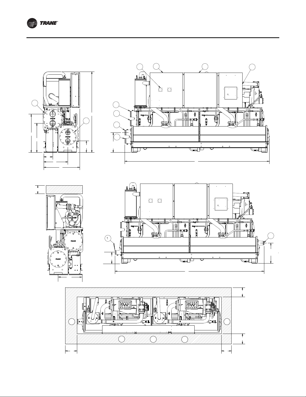
Figure 6. RTWD - 50 Hz dimensions - 70-150 ton SE, 60-120 ton HE
5
11
C
12
H
G
J
F
E
D
4
3
2
1
K
(2 pass evap)
2 pass evap
6
8
( 2 pass evap )
A
7
3 pass evap
S
2
L
(3 pass e
E
( 3 pass evap )
10
M
1
J
( 3 pass evap )
B
N
9
13
14
15
R
N
22 RLC-SVX09H-EN
Page 23
Unit Dimensions/Weights
Table 12. RTWD – 50 Hz – 70-150 ton SE, 60-120 ton HE
RTWD Standard Efficiency High Efficiency
A (2 pass evap)
B (3 pass evap)
C
D
E
F
G
H
J (2 pass evap)
J (3 pass evap)
K (2 pass evap)
L (3 pass evap)
M
N*
R
S
70,80,90,100,110
inch (mm)
138.2 (3510) 138.8 (3525) 126.4 (3210) 127.0 (3225) 127.0 (3225)
142.6 (3621) 145.6 (3621) 130.8 (3321) 130.7 (3320) 130.7 (3320)
75.9 (1929) 76.9 (1955) 76.1 (1933) 76.1 (1933) 76.9 (1955)
34.3 (871) 34.8 (884) 35.1 (890) 35.1 (890) 35.1 (890)
23.6 (600) 23.6 (600) 23.6 (600) 23.6 (600) 23.6 (600)
9.1 (231) 9.1 (231) 9.1 (231) 9.1 (231) 9.1 (231)
27.9 (709) 27.9 (709) 27.9 (709) 27.9 (709) 27.9 (709)
36.6 (929) 36.6 (929) 36.6 (929) 36.6 (929) 36.6 (929)
11.0 (280) 10.6 (268) 10.8 (273) 11.8 (299) 11.8 (299)
10.4 (265) 10.1 (256) 10.2 (258) 11.3 (287) 11.3 (287)
18.9 (479) 19.2 (487) 18.6 (472) 20.4 (519) 20.4 (519)
19.5 (495) 19.5 (496) 19.2 (488) 19.2 (487) 19.2 (487)
36 (914) 36 (914) 36 (914) 36 (914) 36 (914)
36 (914)* 36 (914)* 36 (914)* 36 (914)* 36 (914)*
127 (3226) 127 (3226) 115 (2921) 115 (2921) 115 (2921)
36 (914) 36 (914) 36 (914) 36 (914) 36 (914)
120,130,140,150
inch (mm)
60,70,80
inch (mm)
90
inch (mm)
100,110,120
inch (mm)
Reference
1
2
3
4
5
6
7
8
9
10
11
12
13
14
15
*
**
Evaporator Water Inlet
Evaporator Water Outlet
Condenser Water Inlet
Condenser Water Outlet
Power Disconnect
Power Wire
Control Wire
Control Panel
Condenser Return Waterbox End - minimum clearance (for tube removal)
Condenser Supply Waterbox End - minimum clearance (for maintenance)
Condenser
Evaporator
Panel Power Section - door swing 31.3 inch (796.9 mm)
Panel Power Section - door swing 31.1 inch (790.1 mm)
Panel Control Section - door swing 22.4 inch (568.14 mm)
42 inch (1067 mm) clearance required to other ground parts, two units with panels facing each other or other live parts
require a clearance of 48 inch (1220 mm)
Sound attenuator may increase the footprint - submittal should be used.
RLC-SVX09H-EN 23
Page 24
Unit Dimensions/Weights
Figure 7. RTWD - 50 Hz dimensions - 130-250 ton HE, 160-200 ton PE
K
(2 pass evap)
( 2 pass evap )
A
2 pass evap
3 pass evap
L
(3 pass evap)
( 3 pass evap )
(3 pass evap)
B
P
24 RLC-SVX09H-EN
Page 25

Unit Dimensions/Weights
Table 13. RTWD – 50 Hz dimensions – 130-250 ton HE, 160-200 ton PE
RTWD High Efficiency Premium Efficiency
A (2 pass evap)
B (3 pass evap)
C
D
E
F
G
H
J (2 pass evap)
J (3 pass evap)
K (2 pass evap)
L (3 pass evap)
M
N
P*
R
S
130, 140, 160, 180
inch (mm)
132.3 (3360) 136.1 (3456) 147.9 (3755) 136.1 (3456)
132.8 (3371) 136.1 (3456) 150.8 (3831) 136.1 (3456)
75.6 (1920) 76.8 (1949) 76.8 (1950) 76.9 (1955)
47.3 (1202) 47.8 (1213) 47.3 (1202) 47.8 (1213)
24.6 (624) 24.8 (630) 24.6 (624) 24.8 (630)
11.1 (282) 11.6 (295) 11.1 (282) 11.6 (295)
32.7 (830) 33.1 (840) 33.8 (860) 33.1 (840)
42.4 (1078) 43.9 (1115) 43.6 (1108) 43.9 (1115)
10.1 (256) 10.6 (270) 10.6 (270) 10.6 (270)
9.5 (241) 9.7 (247) 9.7 (247) 9.7 (247)
19.3 (490) 20.6 (524) 20.6 (524) 20.6 (524)
19.9 (505) 21.6 (549) 21.6 (550) 21.6 (549)
36.0 (914) 36.0 (914) 36.0 (914) 36.0 (914)
36.0 (914) 36.0 (914) 36.0 (914) 36.0 (914)
40 (1016)* 40 (1016)* 40 (1016)* 40 (1016)*
114.8 (2916) 114.8 (2916) 134.5 (3416) 134.5 (3416)
36.0 (914) 36.0 (914) 36.0 (914) 36.0 (914)
200, 220, 250
inch (mm)
160, 180
inch (mm)
200
inch (mm)
Reference
1
2
3
4
5
6
7
8
9
10
11
12
13
14
15
*
**
Evaporator Water Inlet
Evaporator Water Outlet
Condenser Water Inlet
Condenser Water Outlet
Power Disconnect
Power Wire
Control Wire
Control Panel
Condenser Return Waterbox End - minimum clearance (for tube removal)
Condenser Supply Waterbox End - minimum clearance (for maintenance)
Condenser
Evaporator
Panel Power Section - door swing 31.3 inch (796.9 mm)
Panel Power Section - door swing 31.1 inch (790.1 mm)
Panel Control Section - door swing 22.4 inch (568.14 mm)
Control panel clearance is 36 or 40 inch (914 or 1016 mm) depending on voltages, starter type, unit application and
local code; 42 inch (1067 mm) clearance required to other grounded parts; two units with panels facing each other
or other live parts require a clearance of 48 inch (1220 mm).
Sound attenuator may increase the footprint - submittal should be used.
RLC-SVX09H-EN 25
Page 26
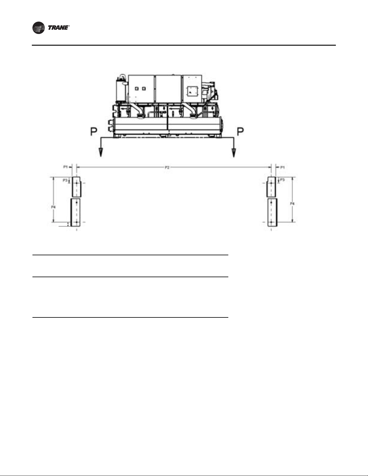
Unit Dimensions/Weights
Figure 8. RTWD/RTUD Unit footprint
P5
Table 14. RTWD/RTUD – unit footprint – all sizes
Standard Efficiency
inch (mm) inch (mm) inch (mm)
P1
P2
P3
P4
P5
Note: Base hole diameters all 0.63 inch (16 mm).
3.68 (93.5) 3.68 (93.5) 3.68 (93.5)
123.78 (3144) 111.97 (2844) 131.65 (3344)
2.43 (61.8) 4.30 (109.3) 4.30 (109.3)
24.93 (633.2) 24.93 (633.2) 24.93 (633.2)
2.5 (64) 2.5 (64) 2.5 (64)
High Efficiency
200 PE (50 Hz)
Premium Efficiency
26 RLC-SVX09H-EN
Page 27
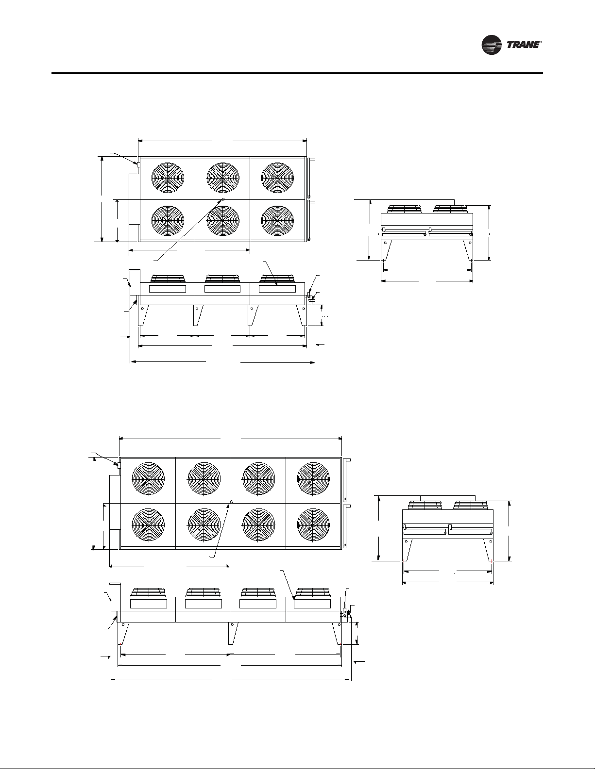
Unit Dimensions/Weights
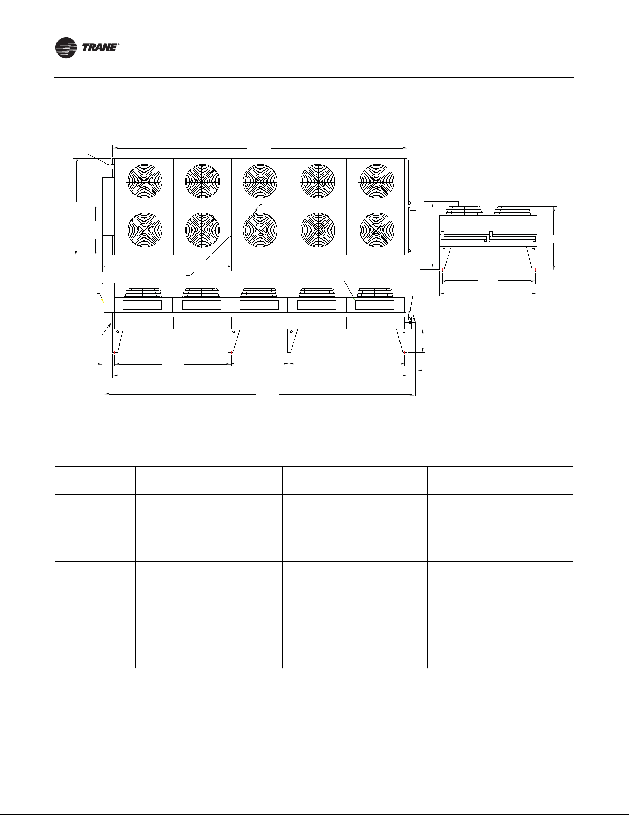
Figure 9. Trane air-cooled condenser -
80T, 150T (cond 1 & 2), 160T (cond 1 & 2), 180T (cond 1)
Disconnect
Approx. center of gravity
Electrical box
split controls
Return bend cover
90.5‚
switch
45.25‚
10.0‚
93.0‚
54.0‚ 54.0‚
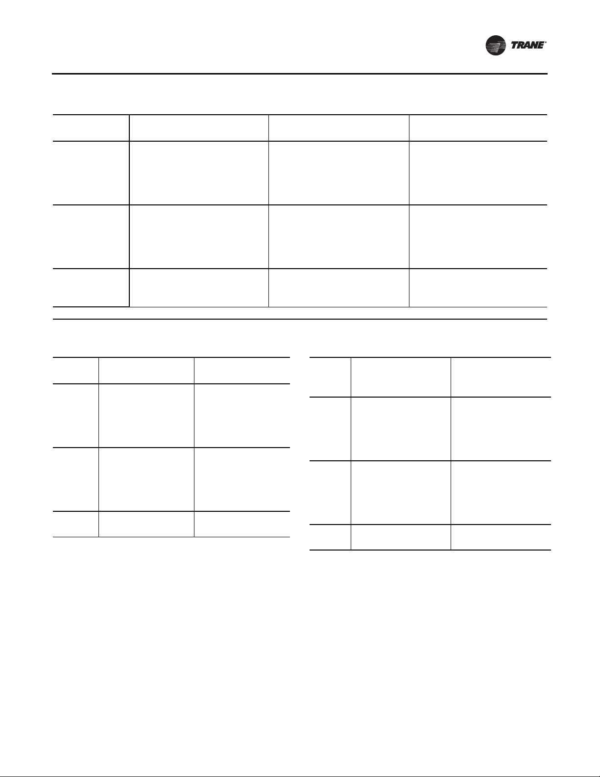
Figure 10. Trane air-cooled condenser -
90T, 100T, 110T, 180T (cond 2), 200T (cond 1 & 2), 220T (cond 1 & 2), 250T (cond1&2)
166.0‚
Service panel
166.0‚
184.0‚
54.0‚
64.0‚
Inlet connection
Outlet connection
22.0‚
8.0‚
58.5‚
86.5‚
90.5‚
0.75 inch anchor holes
Disconnect switch
90.5‚
45.25‚
Electrical box
split controls
Return bend cover
10.0‚
Approx. center of gravity
120.0‚
108.0‚
220.0‚
Service panel
220.0‚
238.0‚
108.0‚
64.0‚
Inlet connection
Outlet connection
22.0‚
8.0‚
0.75 inch anchor holes
58.5‚
86.5‚
90.5‚
RLC-SVX09H-EN 27
Page 28
Unit Dimensions/Weights
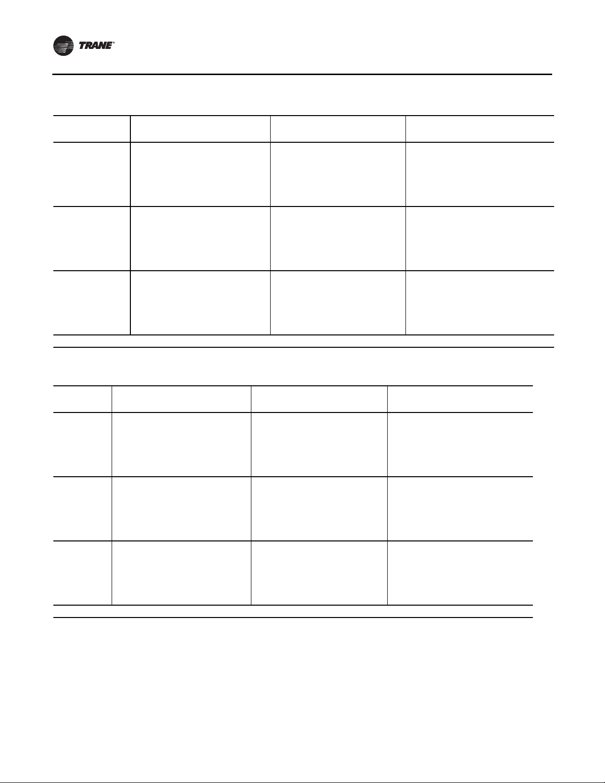
Figure 11. Trane air-cooled condenser - 120T, 130T
Disconnect
switch
90.5‚
45.25‚
Electrical box
split controls
Return
bend cover
10.0‚
Weights
Approx. center of gravity
145.0‚
108.0‚
274.0‚
54.0‚
274.0‚
292.0‚
108.0‚
64.0‚
Inlet connection
Outlet connection
22.0‚
8.0‚
58.5‚
86.5‚
90.5‚
Table 15. Weights - RTWD 60 Hz - IP units
Standard Efficiency High Efficiency Premium Efficiency
Model Operating (lb) Shipping (lb) Operating (lb) Shipping (lb) Operating (lb) Shipping (lb)
80 5900 5703 5732 5551 - -
90 5933 5721 5792 5587 - -
100 6140 5902 6255 6025 - -
110 6332 6074 6475 6208 - -
120 6530 6248 6510 6230 - -
130 6535 6244 6543 6248 - -
140 6971 6649 - - - -
150 - - 7884 7544 8724 8243
160 - - 8395 8036 9171 8691
180 - - 8490 8098 9290 8772
200 - - 8578 8157 9337 8803
220 - - 9493 8995 - -
250 - - 10071 9478 - -
Note: Weights include optional base rail forklifting. Subtract 300 lbs if this option is not selected.
28 RLC-SVX09H-EN
Page 29
Unit Dimensions/Weights
Table 16. Weights - RTWD 60 Hz - SI units
Standard Efficiency High Efficiency Premium Efficiency
Model Operating (kg) Shipping (kg) Operating (kg) Shipping (kg) Operating (kg) Shipping (kg)
80 2676 2587 2600 2518 - -
90 2691 2595 2627 2534 - -
100 2785 2677 2837 2733 - -
110 2872 2755 2937 2816 - -
120 2962 2834 2953 2826 - -
130 2964 2832 2968 2834 - -
140 3162 3016 - - - -
150 - - 3576 3422 3957 3739
160 - - 3808 3645 4160 3942
180 - - 3851 3673 4214 3979
200 - - 3891 3700 4235 3993
220 - - 4306 4080 - -
250 - - 4568 4299 - -
Note: Weights include optional base rail forklifting. Subtract 136.1 kg if this option is not selected.
Table 17. Weights - RTUD - 60 Hz
IP units (lbs) SI units (kg)
Model Operating Shipping Operating Shipping
80 4874 4793 2211 2174
90 4892 4804 2219 2179
100 5073 4974 2301 2256
110 5326 5221 2416 2368
120 5322 5194 2414 2356
130 5322 5194 2414 2356
150 5917 5781 2684 2622
160 6804 6643 3086 3013
180 6876 6715 3119 3046
200 6980 6810 3166 3089
220 7300 7112 3311 3226
250 7602 7401 3448 3357
Note: Weights include optional base rail fork lifting. Subtract 300 lbs if this
option is not selected.
Table 18. Air-Cooled Condenser Weights
RTUD
Tonnage
80 2100 - 953 -
90 2651 - 1202 -
100 2884 - 1308 -
110 2950 - 1338 -
120 4005 - 1817 -
130 4046 - 1835 -
150 2044 2100 927 953
160 2100 2100 953 953
180 2100 2526 953 1146
200 2526 2526 1146 1146
220 2526 2884 1146 1308
250 2884 2884 1308 1308
I-P Units (lbs) SI Units (kg)
Shipping Weight Shipping Weight
Cond 1 Cond 2 Cond 1 Cond 2
RLC-SVX09H-EN 29
Page 30
Unit Dimensions/Weights
Table 19. Weights - RTWD 50 Hz - IP units
Standard Efficiency High Efficiency Premium Efficiency
Model Operating (lb) Shipping (lb) Operating (lb) Shipping (lb) Operating (lb) Shipping (lb)
60 - - 5706 5525 - -
70 5874 5677 5724 5534 - -
80 6030 5807 5893 5680 - -
90 6187 5938 6319 6063 - -
100 6268 6010 6412 6145 - -
110 6332 6014 6495 6220 - -
120 6903 6614 6914 6619 - -
130 7337 7016 8177 7837 - -
140 7342 7020 8245 7884 - -
150 7395 7049 N/A N/A - -
160 - - 8342 7950 9061 8565
180 - - 8770 8351 9579 9030
200 - - 9758 9259 10060 9467
220 - - 9793 9284 - -
250 - - 9958 9398 - -
Note: All weights +/-3%. Weights include optional base rail forklifting. Subtract 300 lbs if this option is not selected.
Table 20. Weights - RTWD 50 Hz - SI units
Standard Efficiency High Efficiency Premium Efficiency
Model Operating (kg) Shipping (kg) Operating (kg) Shipping (kg) Operating (kg) Shipping (kg)
60 - - 2588 2506 - -
70 2664 2575 2596 2510 - -
80 2735 2634 2673 2576 - -
90 2806 2693 2866 2750 - -
100 2843 2726 2908 2787 - -
110 2872 2755 2946 2821 - -
120 3131 3000 3136 3002 - -
130 3328 3182 3709 3555 - -
140 3330 3184 3740 3576 - -
150 3354 3197 - - - -
160 - - 3784 3606 4110 3885
180 - - 3979 3788 4345 4096
200 - - 4426 4200 4563 4294
220 - - 4442 4211 - -
250 - - 4517 4263 - -
Note: Weights include optional base rail forklifting. Subtract 136.1 kg if this option is not selected.
30 RLC-SVX09H-EN
Page 31

Installation - Mechanical
Location Requirements
Noise Considerations
• Refer toTrane Engineering Bulletin -Series R
Sound Ratings and Installation Guide for sound
consideration applications.
• Locate the unit away from sound-sensitive areas.
• Install the isolation pads under the unit. Refer to“Unit
Isolation.”
• Install rubber vibration isolators in all water piping.
• Seal all wall penetrations.
Note: Consult an acoustical engineer for critical
applications.
Foundation
Provide rigid, non-warping mounting pads or a concrete
foundation of sufficient strength and mass to support the
applicable operating weight (i.e., including completed
piping, and full operating charges of refrigerant, oil and
water). See “Unit Dimensions/Weights” chapter for unit
operating weights. Once in place, the unit must be level
within 1/4” (6.4 mm) over its length and width.TheTrane
Company is not responsible for equipment problems
resulting from an improperly designed or constructed
foundation.
Clearances
Provide enough space around the unit to allow the
installation and maintenance personnel unrestricted
access to allservice points. Refer to submittal drawings for
the unit dimensions, to provide sufficient clearance for the
opening of control panel doors and unit service. Refer to
the chapter on “Unit Dimensions/Weights” for minimum
clearances. In all cases, local codes which require
additional clearances will take precedence over these
recommendations.
Note: Required vertical clearance above the unit is 36”
(914.4 mm).There should be no piping or conduit
located over the compressor motor. If the unit
configuration requires a variance to the clearance
dimensions, contact yourTrane Sales Office
Representative. Also refer toTrane Engineering
Bulletins for application information on RTWD/
RTUD chillers.
Chiller
center of gravity dimensions. Refer to the rigging label
attached to the unit for further details.\
WARNING
Heavy Objects!
• Ensure that all the lifting equipment used is properly
rated for the weight of the unit being lifted. Each of
the cables (chains or slings), hooks, and shackles
used to lift the unit must be capable of supporting the
entire weight of the unit.
• Lifting cables (chains or slings) may not be of the
same length. Adjust as necessary for even unit lift.
• The high center of gravity on this unit requires the use
of an anti-rolling cable (chain or sling).To prevent unit
from rolling, attach cable (chain or sling) with no
tension and minimal slack around compressor
suction pipe as shown.
• Do not use fork lift to move or lift unit unless unit has
lifting base with locations marked by caution labels
installed.
Other lifting arrangements could cause equipment or
property damage. Failure to follow instructions above
or properly lift unit could result in unit dropping and
possibly crushing operator/technician which could
result in death or serious injury.
WARNING
Improper Unit Lift!
Test lift unit approximately 24 inches to verify proper
center of gravity lift point. To avoid dropping of unit,
reposition lifting point if unit is not level. Failure to
properly lift unit could result in unit dropping and
possibly crushing operator/technician which could
result in death or serious injury and possible equipment
or property-only damage.
Lifting Procedure
Attach chains or cables to lifting beam, as shown in
Figure .Lifting beam crossbars MUST be positioned so
lifting cables do not contact the sides of the unit. Attach the
anti-rolling cable to the circuit 2 compressor suction pipe.
Adjust as necessary for even level lift.
Rigging
The Model RTWD/RTUD chillershould be moved by lifting,
unless the unit is ordered with the “Base Rail Forklifting”
option. Refer to the unit model number, digit 46, for more
details.
Refer to Table 15, p. 28 thru Table 20, p. 30 for typical unit
lifting weights and Table 30, p. 39 thru Table 35, p. 40 for
RLC-SVX09H-EN 31
Page 32

Installation - Mechanical
Figure 12. RTWD/RTUD rigging
60 Deg. MAX
ANTI-ROLLING CABLE
110” MIN
40” MIN
48” MIN
48” MIN
CG
X
Unit Isolation and Leveling
Mounting
Construct an isolated concrete pad for the unit or provide
concrete footings at each of the four unit mounting points.
Mount the unit directly to the concrete pads or footings.
Level the unit using the base rail as a reference.The unit
must be level within 1/4” over the entire length and width.
Use shims as necessary to level the unit.
Isolation Pads
Note: The elastomeric pads shipped (as standard) are
adequate for most installations. For additional
details on isolation practices, refer toTrane
Engineering Bulletin -Series R
Ratings and Installation Guide, or consult an
acoustical engineer for sound-sensitive
installations.
During final positioning of the unit, place the isolation
pads under the evaporator and condenser tube sheet
supports as shown in Figure 13, p. 33. Level the unit as
described in the next main paragraph.
®
Chiller Sound
CG
Y
Approximate location
of center of gravity
Z
Neoprene Isolator Installation (optional)
Install the optional neoprene isolators at each mounting
location. Isolators are identified by part numberand color.
Refer to submittal drawing for correct isolators.
1. Secure the isolators to the mounting surface, using the
mounting slots in the isolator base plate, as shown in
Figure
. Do not fully tighten theisolator mounting bolts
at this time.
2. Align the mounting holes in the base of the unit, with
the threaded
positioning pins on the top of the isolators.
3. Lower the unit on to the isolators and secure the
isolator to the unit with a nut.
4. Level the unit carefully. Refer to “Leveling”. Fully
tighten the isolator mounting bolts.
32 RLC-SVX09H-EN
Page 33

Installation - Mechanical
Figure 13. Isolator pad placement
Note: Level unit to 1/4” (6.35 mm) across
Figure 14. RTWD/RTUD neoprene isolator
Mounting molded in Neoprene
Note: Level unit to 1/4” (6.35 mm) across
width and length
width and length
L
C
1/2-13NC-2B
A
H (RD)
H (R)
W
D
E
Table 21. Isolator part numbers and dimensions
Isolator Type
Color [Ext]
Max Load-
Model Size Hz Effic. Deflection (in) A B C D E H L W
RTWD
RTWD
RTWD
RTWD
RTUD
RTWD
RTWD
RTWD
RTWD 160, 180, 200 50 PREM
RTUD
(a) See submittal drawing to verify correct isolators.
(b) Part number is X10140305-xx
80, 90, 100, 110,
120, 130, 140
80, 90, 100, 110,
120, 130
70, 80, 90, 100,
110, 120, 130,
140, 150
60,70,80, 90,
100, 110, 120
80, 90, 100, 110,
120, 130
150, 160, 180,
200, 220, 250
150, 160,
180, 200
130, 140, 160,
180, 200, 220,
250
150, 160, 180,
200, 220, 250
60 STD
60 HIGH
50 STD
50 HIGH
60 HIGH
60 HIGH
60 PREM
50 HIGH
60 HIGH
lbs (kg)
RDP-4
Red [62]
2250 (1021)
RDP-4
Green [63]
3000 (1361)
(a)
Maximum Dimension - in (mm)
(b)
3.0
0.50
5.00
5.00
0.56
(14.2)
0.56
(14.2)
0.50
0.50
(76.2)
3.0
(76.2)
(12.7)
0.50
(12.7)
(127.0)
(127.0)
0.38
(9.7)
0.38
(9.7)
2.75
(69.8)
2.75
(69.8)
6.25
(158.8)
6.25
(158.8)
(117.6)
(117.6)
4.63
4.63
RLC-SVX09H-EN 33
Page 34

Installation - Mechanical
Figure 15. Mounting point locations and weights
RTWD - Std efficiency (all)
RTWD - High efficiency, 80-120T (60 Hz), 60-120T (50 Hz)
RTUD - 80-130T
Figure 16. Mounting point locations and weights
RTWD - High efficiency, 150-250T (60Hz), 130-250T (50Hz)
RTWD - Premium efficiency (all)
RTUD - 150-250T
Without panel
With panel
34 RLC-SVX09H-EN
Page 35

Installation - Mechanical
Important: Isolators need to be placed under G1, G2, G3 and G4.
Table 22. RTWD Corner weights, 60 Hz - Figure 15 -lb(kg)
Corner Weights - lb (kg)
Operating Weight-lb (kg)Unit G1 G2 G3 G4
Standard Efficiency
80 1566 (710) 1566 (710) 1385 (628) 1385 (628) 5902 (2676)
90 1571 (713) 1577 (715) 1390 (630) 1396 (633) 5934 (2691)
100 1599 (725) 1617 (733) 1454 (660) 1471 (667) 6141 (2785)
110 1662 (754) 1690 (767) 1477 (670) 1503 (681) 6332 (2872)
120 1689 (766) 1795 (814) 1477 (670) 1569 (712) 6530 (2962)
130 1688 (765) 1797 (815) 1478 (670) 1573 (713) 6536 (2964)
140 1654 (750) 1905 (864) 1586 (719) 1827 (829) 6972 (3162)
High Efficiency
80 1465 (664) 1595 (724) 1279 (580) 1393 (632) 5732 (2600)
90 1479 (671) 1610 (730) 1294 (587) 1409 (639) 5792 (2627)
100 1602 (726) 1704 (773) 1429 (648) 1521 (690) 6256 (2837)
110 1673 (759) 1789 (811) 1457 (661) 1557 (706) 6476 (2937)
120 1680 (762) 1798 (816) 1465 (664) 1569 (711) 6512 (2953)
130 1685 (764) 1808 (820) 1472 (668) 1580 (716) 6545 (2968)
Table 23. RTWD Corner weights, 50 Hz - Figure 15 -lb(kg)
Corner Weights - lb (kg)
Operating Weight-lb (kg)Unit G1 G2 G3 G4
Standard Efficiency
70 1555 (705) 1563 (709) 1375 (624) 1382 (627) 5875 (2664)
80 1560 (708) 1595 (723) 1422 (645) 1454 (659) 6031 (2735)
90 1592 (722) 1655 (751) 1442 (654) 1498 (680) 6187 (2806)
100 1621 (735) 1668 (756) 1468 (666) 1511 (685) 6268 (2843)
110 1662 (754) 1690 (766) 1477 (670) 1503 (681) 6332 (2872)
120 1634 (741) 1872 (852) 1578 (716) 1814 (823) 6905 (3131)
130 1692 (767) 2091 (948) 1590 (721) 1965 (891) 7338 (3328)
140 1696 (769) 2092 (949) 1591 (722) 1964 (891) 7343 (3330)
150 1707 (774) 2107 (956) 1603 (727) 1978 (897) 7395 (3354)
High Efficiency
60 1455 (660) 1592 (722) 1270 (576) 1389 (630) 5706 (2588)
70 1461 (663) 1595 (723) 1275 (578) 1392 (631) 5723 (2596)
80 1468 (666) 1632 (740) 1324 (600) 1471 (667) 5894 (2673)
90 1600 (726) 1747 (792) 1421 (645) 1551 (704) 6320 (2866)
100 1631 (740) 1765 (800) 1448 (657) 1567 (711) 6412 (2908)
110 1678 (761) 1793 (813) 1463 (663) 1563 (709) 6497 (2946)
120 1635 (741) 1894 (859) 1569 (711) 1817 (824) 6914 (3136)
RLC-SVX09H-EN 35
Page 36

Installation - Mechanical
Table 24. RTWD Corner weights, 60 Hz - Figure 16 -lb(kg)
Corner Weights - lb (kg)
Operating Weight-lb (kg)Unit G1 G2 G3 G4
High Efficiency, No Panel
150 1425 (646) 2102 (953) 1482 (672) 2185 (991) 7194 (3262)
160 1524 (691) 2361 (1071) 1498 (680) 2322 (1053) 7706 (3495)
180 1539 (698) 2385 (1081) 1520 (689) 2356 (1068) 7798 (3537)
200 1556 (706) 2410 (1093) 1538 (698) 2383 (1081) 7887 (3577)
220 1712 (777) 2611 (1184) 1769 (802) 2697 (1223) 8789 (3986)
250 1793 (813) 2826 (1282) 1837 (833) 2895 (1313) 9352 (4241)
Premium Efficiency, No Panel
150 1638 (743) 2299 (1043) 1704 (773) 2393 (1085) 8033 (3643)
160 1716 (778) 2525 (1145) 1715 (778) 2524 (1145) 8481 (3846)
180 1736 (787) 2564 (1163) 1737 (788) 2564 (1163) 8601 (3901)
200 1749 (793) 2572 (1166) 1751 (794) 2575 (1168) 8647 (3921)
Table 25. RTWD Corner weights, 60 Hz- Figure 16 -lb(kg)
Corner Weights - lb (kg)
Operating Weight-lb (kg)Unit G1 G2 G3 G4
High Efficiency, With Panel
150 1181 (853) 2010 (911) 1937 (878) 2070 (939) 7897 (3581)
160 1987 (901) 2261 (1025) 1946 (883) 2215 (1004) 8409 (3814)
180 2002 (908) 2284 (1036) 1969 (893) 2246 (1019) 8502 (3856)
200 2020 (916) 2309 (1047) 1989 (902) 2273 (1031) 8590 (3896)
220 2171 (985) 2515 (1141) 2226 (1010) 2579 (1170) 9492 (4305)
250 2256 (1023) 2728 (1237) 2296 (1041) 2776 (1259) 10056 (4560)
Premium Efficiency, With Panel
150 2089 (947) 2195 (996) 2171 (985) 2281 (1035) 8737 (3962)
160 2173 (985) 2416 (1096) 2176 (987) 2420 (1097) 9184 (4165)
180 2194 (995) 2454 (1113) 2198 (997) 2458 (1115) 9304 (4220)
200 2207 (1001) 2461 (1116) 2213 (1004) 2468 (1119) 9350 (4240)
Table 26. RTWD Corner weights, 50 Hz- Figure 16 -lb(kg)
Corner Weights - lb (kg)
Operating Weight-lb (kg)Unit G1 G2 G3 G4
High Efficiency, No Panel
130 1429 (648) 2307 (1046) 1434 (650) 2316 (1050) 7486 (3395)
140 1443 (654) 2328 (1056) 1448 (657) 2336 (1059) 7555 (3426)
160 1465 (664) 2355 (1068) 1469 (666) 2362 (1071) 8069 (3470)
180 1480 (671) 2401 (1089) 1597 (724) 2592 (1175) 8069 (3660)
200 1735 (787) 2724 (1235) 1782 (808) 2798 (1269) 9039 (4099)
220 1748 (793) 2731 (1238) 1794 (814) 2803 (1271) 9075 (4116)
250 1779 (807) 2784 (1263) 1824 (827) 2854 (1294) 9240 (4191)
Premium Efficiency, No Panel
160 1651 (749) 2504 (1136) 1675 (759) 2540 (1152) 8370 (3796)
180 1679 (762) 2590 (1174) 1813 (822) 2796 (1268) 8877 (4026)
200 1785 (809) 2823 (1280) 1833 (831) 2900 (1315) 9341 (4236)
36 RLC-SVX09H-EN
Page 37

Installation - Mechanical
Table 27. RTWD Corner weights, 50 Hz - Figure 16 -lb(kg)
Corner Weights - lb (kg)
Operating Weight-lb (kg)Unit G1 G2 G3 G4
High Efficiency, With Panel
130 1889 (857) 2211 (1003) 1884 (855) 2205 (1000) 8190 (3714)
140 1904 (863) 2231 (1012) 1899 (861) 2225 (1009) 8258 (3745)
160 1927 (874) 2257 (1023) 1921 (871) 2250 (1020) 8355 (3789)
180 1931 (876) 2314 (1049) 2060 (934) 2468 (1119) 8773 (3979)
200 2195 (995) 2628 (1192) 2239 (1015) 2681 (1216) 9743 (4418)
220 2208 (1001) 2635 (1195) 2250 (1021) 2686 (1218) 9779 (4435)
250 2241 (1016) 2686 (1218) 2281 (1035) 2735 (1240) 9943 (4510)
Premium Efficiency, With Panel
160 2106 (955) 2396 (1087) 2138 (970) 2433 (1103) 9073 (4115)
180 2127 (964) 5491 (1130) 2286 (1037) 2677 (1214) 9580 (4345)
200 2245 (1018) 2723 (1235) 2291 (1039) 2778 (1260) 10045 (4555)
Table 28. RTUD Corner weights, 60 Hz - Figure 15 -lb(kg)
Corner Weights - lb (kg)
Operating Weight-lb (kg)Unit G1 G2 G3 G4
High Efficiency
80 1331 (605) 1254 (570) 1173 (533) 1104 (502) 4874 (2211)
90 1338 (608) 1258 (572) 1179 (536) 1109 (504) 4892 (2219)
100 1357 (617) 1280 (582) 1247 (567) 1177 (535) 5073 (2301)
110 1454 (661) 1357 (617) 1296 (589) 1210 (550) 5326 (2416)
120 1468 (666) 1367 (620) 1310 (594) 1219 (553) 5366 (2434)
130 1468 (666) 1367 (620) 1310 (594) 1219 (553) 5366 (2434)
Table 29. RTUD Corner weights, 60 Hz - Figure 16 -lb(kg)
Corner Weights - lb (kg)
Operating Weight-lb (kg)Unit G1 G2 G3 G4
High Efficiency, No Panel
150 964 (438) 1399 (636) 1168 (531) 1698 (772) 5240 (2377)
160 1087 (494) 1775 (807) 1221 (555) 1995 (907) 6089 (2762)
180 1111 (505) 1780 (809) 1252 (569) 2992 (910) 6158 (2793)
200 1162 (528) 1813 (824) 1276 (580) 1991 (905) 6257 (2838)
220 1148 (522) 1837 (835) 1377 (626) 2200 (1000) 6576 (2983)
250 1192 (542) 1956 (889) 1406 (639) 2308 (1049) 6878 (3120)
High Efficiency, With Panel
150 1242 (564) 1549 (704) 1386 (630) 1729 (786) 5917 (2684)
160 1522 (692) 1709 (777) 1676 (762) 1881 (855) 6803 (3086)
180 1549 (704) 1714 (779) 1707 (776) 1890 (859) 6876 (3119)
200 1606 (730) 1745 (793) 1731 (787) 1881 (855) 6980 (3166)
220 1582 (719) 1782 (810) 1844 (838) 2077 (944) 7300 (3311)
250 1628 (740) 1901 (864) 1872 (851) 2185 (993) 7602 (3448)
RLC-SVX09H-EN 37
Page 38

Installation - Mechanical
Center of Gravity
Figure 17. Center of gravity
RTWD - Std efficiency (all)
RTWD - High efficiency, 80-120T (60 Hz), 60-120T (50 Hz)
RTUD - 80-130T
Figure 18. Center of gravity
RTWD - High efficiency, 150-250T (60Hz), 130-250T (50Hz)
RTWD - Premium efficiency (all)
RTUD - 150-250T
Without panel
With panel
38 RLC-SVX09H-EN
Page 39

Installation - Mechanical
Table 30. RTWD Center of gravity, 60Hz - Figure 17 - in (mm)
Standard Efficiency
High Efficiency
Unit X Y Z X Y Z
80 61 (1543) 34 (868) 15 (381) 55 (1393) 35 (879) 16 (394)
90 61 (1544) 34 (868) 15 (381) 55 (1395) 35 (877) 16 (394)
100 62 (1566) 35 (879) 15 (382) 55 (1409) 34 (869) 15 (390)
110 61 (1547) 35 (891) 15 (383) 55 (1391) 35 (880) 15 (391)
120 60 (1534) 34 (876) 15 (390) 55 (1393) 35 (879) 15 (391)
130 60 (1535) 35 (876) 15 (391) 55 (1394) 35 (879) 15 (392)
140 63 (1607) 36 (903) 16 (403) - - -
Table 31. RTWD Center of gravity, 50Hz - Figure 17 - in (mm)
Standard Efficiency
Unit X Y Z X Y Z
60 - - - 55 (1393) 35 (879) 16 (395)
70 61 (1543) 34 (868) 15 (381) 55 (1393) 35 (878) 16 (395)
80 62 (1567) 34 (875) 15 (384) 56 (1416) 35 (885) 16 (397)
90 61 (1562) 35 (882) 15 (387) 55 (1405) 34 (871) 16 (395)
100 61 (1562) 35 (886) 15 (385) 55 (1405) 34 (876) 15 (393)
110 61 (1547) 35 (891) 15 (383) 55 (1393) 35 (879) 15 (391)
120 63 (1612) 36 (905) 16 (403) 57 (1460) 36 (907) 16 (404)
130 63 (1591) 37 (929) 16 (414) 55 (1393) 35 (879) 16 (395)
140 63 (1590) 37 (929) 16 (414) - - -
150 63 (1590) 37 (927) 16 (414) - - -
High Efficiency
Table 32. RTWD Center of gravity, 60Hz - Figure 18 - in (mm)
High Efficiency
Unit X Y Z X Y Z
No Panel
150 60 (1518) 38 (959) 17 (441) 70 (1773) 37 (949) 17 (434)
160 58 (1478) 39 (989) 18 (449) 68 (1740) 39 (980) 17 (441)
180 58 (1481) 39 (987) 18 (449) 68 (1740) 38 (978) 17 (442)
200 58 (1482) 39 (985) 18 (449) 68 (1741) 38 (977) 17 (441)
220 60 (1513) 40 (1006) 18 (446) - - -
250 59 (1507) 40 (1019) 18 (451) - - -
With Panel
150 59 (1511) 39 (995) 15 (391) 70 (1772) 39 (986) 15 (388)
160 58 (1475) 40 (1020) 16 (401) 68 (1741) 40 (1012) 16 (397)
180 58 (1478) 40 (1018) 16 (401) 69 (1742) 40 (1010) 16 (398)
200 58 (1479) 40 (1016) 16 (402) 69 (1742) 40 (1008) 16 (398)
220 59 (1508) 41 (1035) 16 (404) - - -
250 59 (1502) 41 (1046) 16 (411) - - -
Premium Efficiency
RLC-SVX09H-EN 39
Page 40

Installation - Mechanical
Table 33. RTWD Center of gravity, 50Hz - Figure 18 - in (mm)
High Efficiency
Unit X Y Z X Y Z
No Panel
120 59 (1493) 39 (988) 18 (455) - - -
140 59 (1492) 39 (986) 18 (455) - - -
160 59 (1492) 39 (983) 18 (454) 69 (1752) 38 (974) 17 (446)
180 61 (1544) 39 (1002) 18 (456) 71 (1804) 39 (993) 18 (448)
200 59 (1509) 40 (1025) 18 (451) 59 (1509) 40 (1021) 18 (452)
220 59 (1509) 40 (1023) 18 (450) - - -
250 59 (1508) 40 (1020) 18 (450) - - -
With Panel
120 59 (1488) 40 (1020) 16 (405) - - -
140 59 (1488) 40 (1018) 16 (406) - - -
160 59 (1488) 40 (1015) 16 (406) 69 (1752) 40 (1007) 16 (401)
180 60 (1536) 41 (1031) 16 (409) 71 (1800) 40 (1023) 16 (406)
200 59 (1504) 41 (1052) 16 (409) 59 (1504) 41 (1047) 16 (411)
220 59 (1504) 41 (1050) 16 (409) - - -
250 59 (1503) 41 (1047) 16 (409) - - -
Premium Efficiency
Evaporator Piping
Table 34. RTUD Center of gravity, 60Hz- Figure 17-in
(mm)
High Efficiency
Unit X Y Z
80 55 (1400) 35 (895) 15 (371)
90 55 (1400) 35 (894) 15 (371)
100 56 (1430) 36 (906) 15 (372)
110 55 (1408) 36 (909) 15 (370)
120 55 (1408) 36 (908) 15 (369)
130 55 (1408) 36 (908) 15 (369)
Table 35. RTUD Center of gravity, 60Hz- Figure 18-in
(mm)
High Efficiency
Unit X Y Z
No Panel
150 64 (1627) 38 (959) 17 (439)
160 62 (1573) 41 (1034) 18 (457)
180 62 (1574) 41 (1037) 18 (454)
200 61 (1557) 41 (1037) 18 (450)
220 64 (1618) 42 (1055) 18 (454)
250 63 (1607) 42 (1070) 18 (457)
With Panel
150 62 (1568) 38 (973) 16 (416)
160 61 (1558) 42 (1067) 16 (399)
180 61 (1559) 42 (1069) 16 (397)
200 61 (1543) 42 (1069) 16 (394)
220 63 (1599) 43 (1084) 16 (399)
250 63 (1589) 43 (1097) 16 (405)
Thoroughly flush allwaterpiping to the unit before making
the final piping connections to the unit.
Components and layout will vary slightly, depending on
the location of connections and the water source.
NOTICE:
Evaporator Damage!
The chilled water connections to the evaporator are to
be grooved-pipe type connections. Do not attempt to
weld these connections, as the heat generated from
welding can cause microscopic and macroscopic
fractures on the cast iron waterboxes that can lead to
premature failure of the waterbox.To prevent damage
to chilled water components, do not allow evaporator
pressure (maximum working pressure) to exceed 150
psig (10.5 bar).
NOTICE:
Equipment Damage!
If using an acidic commercial flushing solution when
flushing the water piping, construct a temporary
bypass around the unit to prevent damage to internal
components of the evaporator.
NOTICE:
Equipment Damage!
To prevent evaporator or condenser damage, pipe
strainers must be installed in the water supplies to
protect components from water born debris. Trane is
not responsible for equipment-only-damage caused by
water born debris.
40 RLC-SVX09H-EN
Page 41

Installation - Mechanical
NOTICE:
Proper Water Treatment!
The use of untreated or improperly treated water could
result in scaling, erosion, corrosion, algae or slime. It is
recommended that the services of a qualified water
treatment specialist be engaged to determine what
water treatment, if any, is required.Trane assumes no
responsibility for equipment failures which result from
untreated or improperly treated water, or saline or
brackish water.
Drainage
Locate the unit near a large capacity drain for water vessel
drain-down during shutdown or repair. Condensers and
evaporators are provided with drain connections. Refer to
“Water Piping.” All local and national codes apply.
A vent is provided on the top of the evaporator at the
return end. Be sure to provide additional vents at high
points in the piping to bleed air from the chilled water
system. Install necessary pressure gauges to monitor the
entering and leaving chilled water pressures.
Provide shutoff valves in lines to the gauges to isolate
them from the system when they are not in use. Use
rubber vibration eliminators to prevent vibration
transmission through the water lines.
If desired, install thermometers in lines to monitor
entering and leaving water temperatures. Install a
balancing valve in leaving water line to control water flow
balance. Install shutoff valves on both entering and
leaving water lines to isolate evaporator for service.
A pipe strainer must be installed in entering water line to
prevent water-borne debris from entering the evaporator.
Reversing Water Boxes
NOTICE:
Equipment Damage!
Do NOT rotate or swap evaporator or condenser water
boxes end-for-end. Altering water boxes can affect
equipment operation and can cause equipment
damage.
Water boxes on evaporator and condenser can NOT be
rotated or swapped end for end. Altering water boxes will
lead to poor efficiency, poor oil management and possible
freeze-up of evaporator.
Figure 19. RTWD water boxes
Evaporator Piping Components
“Piping components” include all devices and controls
used to provide proper water system operation and unit
operating safety.These components and their general
locations are given below.
Entering Chilled Water Piping - Field Installed
• Air vents (to bleed air from system)
• Water pressure gauges with shutoff valves
• Vibration eliminators
• Shutoff (isolation) valves
• Thermometers (if desired)
• Cleanout tees
• Relief valve
• Pipe strainer
NOTICE:
Water Born Debris!
To prevent evaporator or condenser damage, pipe
strainers must be installed in the water supplies to
protect components from water born debris. Trane is
not responsible for equipment-only-damage caused by
water born debris.
NOTICE:
Evaporator Damage!
The chilled water connections to the evaporator are to
be grooved-pipe type connections. Do not attempt to
weld these connections, as the heat generated from
welding can cause microscopic and macroscopic
fractures on the cast iron waterboxes that can lead to
premature failure of the waterbox.To prevent damage
to chilled water components, do not allow evaporator
pressure (maximum working pressure) to exceed 150
psig (10.5 bar).
Leaving Chilled Water Piping - Field Installed
• Air vents (to bleed air from system)
• Water pressure gauges with shutoff valves
• Vibration eliminators
• Shutoff (isolation) valves
• Thermometers
• Cleanout tees
• Balancing valve
• Flow Switch (not required if factory installed flow
switch option is selected)
Evaporator Flow Switch (Optional)
If factory installed flow switch option is selected, switch is
programmed based on the operating conditions
submitted with the order.The leaving evaporator
temperature, fluid type and fluid concentration affect the
selected flow switch. If the operating conditions on the job
site change, the flow switch may need to be replaced.
RLC-SVX09H-EN 41
Page 42

Installation - Mechanical
The sensor head includes 3 LEDs, two yellow and one
green.Wait 15 seconds after poweris applied to the sensor
before evaluating LEDs for flow status. When wired
correctly and flow is established, only the green LED
should be lit. Following are the LED indicators:
• Green ON, both yellow OFF — Flow
• Green and outside yellow ON — No Flow
• Center yellow ON continuously — Miswire
NOTICE:
Proper Water Treatment!
The use of untreated or improperly treated water in this
equipment could result in scaling, erosion, corrosion,
algae or slime. It is recommended that the services of a
qualified water treatment specialist be engaged to
determine what water treatment, if any, is required.
Trane assumes no responsibility for equipment failures
which result from untreated or improperly treated
water, or saline or brackish water.
Important: If using an acidic commercial flushing
solution, construct a temporary bypass
around the unit to prevent damage to
internal components of the evaporator.
Dirt, scale, products of corrosion and other foreign
material will adversely affect heat transfer between the
water and system components. Foreign matter in the
chilled water system can also increase pressure drop and,
consequently, reduce water flow. Proper water treatment
must be determined locally, depending on the type of
system and local water characteristics.
Neither salt nor brackish water is recommended for use in
Trane air-cooled Series R
to a shortened life to an indeterminable degree.TheTrane
Company encourages the employment of a reputable
water treatment specialist, familiar with local water
conditions, to assist in this determination and in the
establishment of a proper water treatment program.
Using untreated or improperly treated water in these units
may result in inefficient operation and possible tube
damage. Consult a qualified water treatment specialist to
determine whether treatment is needed.
Indexing Flow Switch
To properly index the flow switch, the following
requirements must be met:
• Dot must be at a position no greater than 90° off Index.
• Torque must be between 22 ft-lb min and 74 ft-lb max.
• A minimum distance of 5x pipe diameter must be
maintained between flow switch and any bends,
valves, changes in cross sections, etc.
®
chillers. Use of either will lead
Figure 20. Proper flow switch indexing
To p V ie w
Flow
The flow switch must have the dot in the shaded area
to the left of this line for proper indexing (±90° off Index)
Index
Flow Proving Devices
NOTICE:
Evaporator Damage!
For all RTUD units, chilled water pumps MUST be
controlled by the Trane CH530 to avoid catastrophic
damage to the evaporator due to freezing.
Important: If factory installed flow switch option is not
selected, installer must provide flow
switches or differential pressure switches
with pump interlocks to prove water flow.
To providechillerprotection, install and wire flowswitches
in series with the water pump interlocks, for both chilled
water and condenser water circuits (see “Installation -
Electrical” chapter). Specific connections and schematic
wiring diagrams are shipped with the unit.
Flow switchesmust prevent or stop compressor operation
if either system water flow drops off below the required
minimum shown on the pressure drop curves. Follow the
manufacturer’s recommendations for selection and
installation procedures. Generalguidelines for flowswitch
installation are outlined below.
• Mount the switch upright, with a minimum of 5 pipe
diameters straight, horizontal run on each side.
• Do not install close to elbows, orifices or valves.
Note: The arrow on switch must point in direction of
water flow.
• To prevent switch fluttering, remove all air from water
system.
Note: CH530 provides a 6-sec time delay on flow switch
input before shutting down unit on loss-of-flow
diagnostic. Contact aqualified service organization
if nuisance machine shutdowns persist.
• Adjust switch to open when water flow falls below
minimum. See General Data tables for minimum flow
recommendations. Flow switch is closed on proof of
water flow.
NOTICE:
Evaporator Damage!
To prevent evaporator damage, do not use water flow
switch to cycle the system.
42 RLC-SVX09H-EN
Page 43

Installation - Mechanical
0.0
5.0
10.0
15.0
20.0
25.0
30.0
35.0
40.0
45.0
0.0 50.0 100.0 150.0 200.0 250.0 300.0 350.0 400.0 450.0 500.0
Pressure Drop (ft. H2O)
Water Flow (GPM)
Waterside Pressure Drop - 60 Hz Units - 2 Pass Evaporator
RTWD080 Std
RTWD090 Std
RTWD100 Std
RTWD110 Std
RTWD120 Std
RTWD130 Std
RTWD140 Std
RTWD80 High
RTWD90 High
RTWD100 High &
RTUD110 High
RTWD110 High &
RTUD120, 130 High
RTWD120 High &
RTUD150 High
RTWD130 High
Pressure Drop Curves
For overlapping pressure drop curves, see General Data tables in section “General Information,” p. 9 for limit values.
Figure 21. Evaporator pressure drop curves - 2 pass, 60 Hz - RTWD, RTUD
RLC-SVX09H-EN 43
Page 44

Installation - Mechanical
0.0
5.0
10.0
15.0
20.0
25.0
30.0
35.0
40.0
45.0
50.0
0.0 100.0 200.0 300.0 400.0 500.0 600.0 700.0 800.0 900.0
Pressure Drop (ft. H2O)
Water Flow (GPM)
Waterside Pressure Drop - 60 Hz Units - 2 Pass Evaporator
RTWD150 High
RTWD160 High
RTWD180 High
RTWD200 High
RTWD220 High
RTWD250 High
RTWD150 Prem
RTWD160 Prem
RTWD180 Prem
RTWD200 Prem
Figure 22. Evaporator pressure drop curves - 2 pass, 60 Hz - RTWD, RTUD
44 RLC-SVX09H-EN
Page 45

Installation - Mechanical
0.0
5.0
10.0
15.0
20.0
25.0
30.0
35.0
40.0
45.0
0.0 50.0 100.0 150.0 200.0 250.0 300.0 350.0 400.0 450.0 500.0
Pressure Drop (ft. H2O)
Water Flow (GPM)
Waterside Pressure Drop - RTWD 50Hz/RTUD 60Hz Units - 2 Pass Evaporator
RTWD70 Std 50Hz
RTWD80 Std 50Hz
RTWD90 Std 50Hz
RTWD100 Std 50Hz
RTWD110 Std 50Hz
RTWD120 Std 50Hz
RTWD130 Std 50Hz
RTWD140 Std 50Hz
RTWD150 Std 50Hz
RTWD60 High 50Hz &
RTUD80 High 60Hz
RTWD70 High 50Hz &
RTUD90 High 60Hz
RTWD80 High 50Hz &
RTUD100 High 60Hz
RTWD90 High 50Hz
RTWD100 High 50Hz
RTWD110 High 50Hz
RTWD120 High 50Hz
Figure 23. Evaporator pressure drop curves - 2 pass - RTWD 50 Hz, RTUD 60 Hz
RLC-SVX09H-EN 45
Page 46

Installation - Mechanical
0.0
5.0
10.0
15.0
20.0
25.0
30.0
35.0
40.0
45.0
50.0
50.0 150.0 250.0 350.0 450.0 550.0 650.0 750.0 850.0
Pressure Drop (ft. H2O)
Water Flow (GPM)
Waterside Pressure Drop - 50 Hz Units - 2 Pass Evaporator
RTWD130 High
RTWD140 High
RTWD160 High
RTWD180 High
RTWD200 High
RTWD220 High
RTWD250 High
RTWD160 Prem
RTWD180 Prem
RTWD200 Prem
Figure 24. Evaporator pressure drop curves - 2 pass, 50 hz - RTWD
46 RLC-SVX09H-EN
Page 47

Installation - Mechanical
0.0
10.0
20.0
30.0
40.0
50.0
60.0
70.0
0.0 50.0 100.0 150.0 200.0 250.0 300.0 350.0 400.0
Pressure Drop (ft. H2O)
Water Flow (GPM)
Waterside Pressure Drop - 60 Hz Units - 3 Pass Evaporator
RTWD080 Std
RTWD090 Std
RTWD100 Std
RTWD110 Std
RTWD120 Std
RTWD130 Std
RTWD140 Std
RTWD80 High
RTWD90 High
RTWD100 High &
RTUD110 High
RTWD110 High &
RTUD120, 130 High
RTWD120 High &
RTUD150 High
RTWD130 High
Figure 25. Evaporator pressure drop curves - 3 pass, 60 hz - RTWD, RTUD
RLC-SVX09H-EN 47
Page 48

Installation - Mechanical
0.0
10.0
20.0
30.0
40.0
50.0
60.0
70.0
80.0
0.0 100.0 200.0 300.0 400.0 500.0 600.0
Pressure Drop (ft. H2O)
Water Flow (GPM)
Waterside Pressure Drop - 60 Hz Units - 3 Pass Evaporator
RTWD150 High &
RTUD160, 180 High
RTWD160 High &
RTUD200 High
RTWD180 High &
RTUD 220 High
RTWD200 High &
RTUD 250 High
RTWD220 High
RTWD250 High
RTWD150 Prem
RTWD160 Prem
RTWD180 Prem
RTWD200 Prem
Figure 26. Evaporator pressure drop curves - 3 pass, 60 hz - RTWD, RTUD
48 RLC-SVX09H-EN
Page 49

Installation - Mechanical
0.0
10.0
20.0
30.0
40.0
50.0
60.0
70.0
0.0 50.0 100.0 150.0 200.0 250.0 300.0 350.0 400.0
Pressure Drop (ft. H2O)
Water Flow (GPM)
Waterside Pressure Drop - RTWD 50Hz/RTUD 60 Hz Units - 3 Pass Evaporator
RTWD70 Std 50Hz
RTWD80 Std 50Hz
RTWD90 Std 50Hz
RTWD100 Std 50Hz
RTWD110 Std 50Hz
RTWD120 Std 50Hz
RTWD130 Std 50Hz
RTWD140 Std 50Hz
RTWD150 Std 50Hz
RTWD60 High 50Hz &
RTUD80 High 60Hz
RTWD70 High 50Hz &
RTUD90 High 60Hz
RTWD80 High 50Hz &
RTUD100 High 60Hz
RTWD90 High 50Hz
RTWD100 High 50Hz
RTWD110 High 50Hz
RTWD120 High 50Hz
Figure 27. Evaporator pressure drop curves - 3 pass - RTWD 50 Hz, RTUD 60 Hz
RLC-SVX09H-EN 49
Page 50

Installation - Mechanical
0.0
10.0
20.0
30.0
40.0
50.0
60.0
70.0
80.0
50.0 150.0 250.0 350.0 450.0 550.0
Pressure Drop (ft. H2O)
Water Flow (GPM)
Waterside Pressure Drop - 50 Hz Units - 3 Pass Evaporator
RTWD130 High
RTWD140 High
RTWD160 High
RTWD180 High
RTWD200 High
RTWD220 High
RTWD250 High
RTWD160 Prem
RTWD180 Prem
RTWD200 Prem
Figure 28. Evaporator pressure drop curves - 3 pass, 50 Hz - RTWD
50 RLC-SVX09H-EN
Page 51

Installation - Mechanical
0.0
5.0
10.0
15.0
20.0
25.0
30.0
35.0
40.0
0.0 100.0 200.0 300.0 400.0 500.0 600.0 700.0
Pressure Drop (ft. H2O)
Water Flow (GPM)
Waterside Pressure Drop - 60 Hz Units - Condenser
RTWD080 Std
RTWD090 Std
RTWD100 Std
RTWD110 Std
RTWD120 Std
RTWD130 Std
RTWD140 Std
RTWD80 High
RTWD90 High
RTWD100 High
RTWD110 High
RTWD120 High
RTWD130 High
Figure 29. Condenser pressure drop curves - RTWD 60 Hz
RLC-SVX09H-EN 51
Page 52

Installation - Mechanical
0.0
5.0
10.0
15.0
20.0
25.0
30.0
35.0
40.0
45.0
0.0 200.0 400.0 600.0 800.0 1000.0 1200.0
Pressure Drop (ft. H2O)
Water Flow (GPM)
Waterside Pressure Drop - 60 Hz Units - Condenser
RTWD150 High
RTWD160 High
RTWD180 High
RTWD200 High
RTWD220 High
RTWD250 High
RTWD150 Prem
RTWD160 Prem
RTWD180 Prem
RTWD200 Prem
Figure 30. Condenser pressure drop curves - RTWD 60 Hz
52 RLC-SVX09H-EN
Page 53

Installation - Mechanical
0.0
5.0
10.0
15.0
20.0
25.0
30.0
35.0
40.0
0.0 100.0 200.0 300.0 400.0 500.0 600.0 700.0
Pressure Drop (ft. H2O)
Water Flow (GPM)
Waterside Pressure Drop - 50 Hz Units - Condenser
RTWD70 Std 50Hz
RTWD80 Std 50Hz
RTWD90 Std 50Hz
RTWD100 Std 50Hz
RTWD110 Std 50Hz
RTWD120 Std 50Hz
RTWD130 Std 50Hz
RTWD140 Std 50Hz
RTWD150 Std 50Hz
RTWD60 High 50Hz
RTWD70 High 50Hz
RTWD80 High 50Hz
RTWD90 High 50Hz
RTWD100 High 50Hz
RTWD110 High 50Hz
RTWD120 High 50Hz
Figure 31. Condenser pressure drop curves - RTWD 50 Hz
RLC-SVX09H-EN 53
Page 54

Installation - Mechanical
0.0
5.0
10.0
15.0
20.0
25.0
30.0
35.0
40.0
45.0
100.0 300.0 500.0 700.0 900.0 1100.0
Pressure Drop (ft. H2O)
Water Flow (GPM)
Waterside Pressure Drop - 50 Hz Units - Condenser
RTWD130 High
RTWD140 High
RTWD160 High
RTWD180 High
RTWD200 High
RTWD220 High
RTWD250 High
RTWD160 Prem
RTWD180 Prem
RTWD200 Prem
Figure 32. Condenser pressure drop curves - RTWD 50 Hz
54 RLC-SVX09H-EN
Page 55

Installation - Mechanical
Low Evap Refrigerant Cutout/Percent Glycol Recommendations
The table below shows the low evaporator temperature
cutout for different glycol levels.
Additional glycol beyond the recommendations will
adversely effect unit performance.The unit efficiency will
be reduced and the saturated evaporator temperature will
Table 36. Low evaporator refrigerant temperature cutout (LRTC) and low water temperature cutout (LWTC)
Ethylene Glycol Propylene Glycol
Glycol
Percentage
(%)
0 32.0 28.6 35.0 0 32.0 28.6 35.0
2 31.0 27.6 34.0 2 31.0 27.6 34.0
4 29.7 26.3 32.7 4 29.9 26.5 32.9
5 29.0 25.6 32.0 5 29.3 25.9 32.3
6 28.3 24.9 31.3 6 28.7 25.3 31.7
8 26.9 23.5 29.9 8 27.6 24.2 30.6
10 25.5 22.1 28.5 10 26.4 23.0 29.4
12 23.9 20.5 26.9 12 25.1 21.7 28.1
14 22.3 18.9 25.3 14 23.8 20.4 26.8
15 21.5 18.1 24.5 15 23.1 19.7 26.1
16 20.6 17.2 23.6 16 22.4 19.0 25.4
18 18.7 15.3 21.7 18 20.9 17.5 23.9
20 16.8 13.4 19.8 20 19.3 15.9 22.3
22 14.7 11.3 17.7 22 17.6 14.2 20.6
24 12.5 9.1 15.5 24 15.7 12.3 18.7
25 11.4 8.0 14.4 25 14.8 11.4 17.8
26 10.2 6.8 13.2 26 13.8 10.4 16.8
28 7.7 4.3 10.7 28 11.6 8.2 14.6
30 5.1 1.7 8.1 30 9.3 5.9 12.3
32 2.3 -1.1 5.3 32 6.8 3.4 9.8
34 -0.7 -4.1 5.0 34 4.1 0.7 7.1
35 -2.3 -5.0 5.0 35 2.7 -0.7 5.7
36 -3.9 -5.0 5.0 36 1.3 -2.1 5.0
38 -7.3 -5.0 5.0 38 -1.8 -5.0 5.0
40 -10.8 -5.0 5.0 40 -5.2 -5.0 5.0
42 -14.6 -5.0 5.0 42 -8.8 -5.0 5.0
44 -18.6 -5.0 5.0 44 -12.6 -5.0 5.0
45 -20.7 -5.0 5.0 45 -14.6 -5.0 5.0
46 -22.9 -5.0 5.0 46 -16.7 -5.0 5.0
48 -27.3 -5.0 5.0 48 -21.1 -5.0 5.0
50 -32.1 -5.0 5.0 50 -25.8 -5.0 5.0
Solution
Freeze Point
(°F)
Minimum
Recommended
LRTC (°F)
Minimum
Recommended
LWTC (°F)
be reduced. For some operating conditions this effect can
be significant.
If additional glycol is used, then use the actual percent
glycol to establish the low refrigerant cutout setpoint.
Glycol
Percentage
(%)
Solution
Freeze Point
(°F)
Minimum
Recommended
LRTC (°F)
Minimum
Recommended
LWTC (°F)
RLC-SVX09H-EN 55
Page 56

Installation - Mechanical
Condenser Water Piping (RTWD Units Only)
Condenser water inletand outlet types,sizes and locations
are given in the Unit Dimensions andWeights. Condenser
pressure drops are shown inFigure 29, p. 51 thru
Figure 32, p. 54.
Condenser Piping Components
Condenser piping components and layout vary,
depending on location of connections and water source.
Condenser piping components generally function
identically to those in the evaporator piping system, as
described in "Evaporator Piping" on Page 40. In addition,
cooling tower systems should include a manual or
automatic bypass valve that can alter the water flow rate,
to maintain condensing pressure. Well water (or city
water) condensing systems should include a pressure
reducing valve and a water regulating valve.
Pressure reducing valve should be installed to reduce
water pressure entering the condenser. This is required
only if the water pressure exceeds 150 psig.This is
necessary to prevent damage to the disc and seat of the
water regulating valve that can be caused by excessive
pressure drop throughthe valve andalso due tothe design
of the condenser. Condenser waterside is rated at 150 psi.
NOTICE:
Equipment Damage!
To prevent damage to the condenser or regulating
valve, the condenser water pressure should not exceed
150 psig.
Water Regulating Valve (RTWD Only)
The Condenser Head PressureControl Option provides for
a 0-10V (maximum range - a smaller range is adjustable)
output interface to the customer’s condenser water flow
device. Refer to RLC-PRB021-EN for further details
regarding condenser water temperature control.
The following guidelines must be met in order to ensure
adequate oil circulation throughout the system.
• The RTWD requiresa minimum pressure differential of
25 psid (172.1 kPA) at all load conditions in order to
ensure adequate oil circulation.
• The entering condenser water temperature must be
above 55°F (12.8°C), or between 45°F (7.2°C) and 55°F
(12.8°C) with a 1°F (0.6°C) temperature rise per minute
up to 55°F (12.8°C).
• The leaving condenser water temperature must be
17°F (9.4°C) degrees higher than leaving evaporator
water temperature within 2 minutes of startup. A 25°F
(13.9°C) temperature differential must be maintained
thereafter. (This differential requirement is lessenedby
0.25°F [0.14°C] for every 1°F [0.6°C] that the leaving
condenser water temperature is above 55°F [12.8°C].)
If the above guidelines cannot be met, then some form of
condenser water temperature control must be used.
Note: Plugged tees are installed to provide access for
chemical cleaning of the condenser tubes.
Condenser piping must be in accordance with all
applicable local and national codes.
Condenser Drains
The condenser shells can be drained by removing the
drain plugs from the bottom of the condenser heads. Also,
remove the vent plugs at the top of the condenser heads
to facilitate complete drainage.
When the unit is shipped, the drain plugs are removed
from the condenser and placed in a plastic bag in the
control panel, along with the evaporator drain plug.The
condenser drains may be connected to suitable drains to
permit drainage during unit servicing. If they are not, the
drain plugs must be installed.
Water Treatment
Using untreated or improperly treated water in these units
may result in inefficient operation and possible tube
damage. Consult a qualified water treatment specialist to
determine whether treatment is needed.The following
disclamatory label is provided on each RTWD unit:
NOTICE:
Proper Water Treatment!
The use of untreated or improperly treated water could
result in scaling, erosion, corrosion, algae or slime. It is
recommended that the services of a qualified water
treatment specialist be engaged to determine what
water treatment, if any, is required.Trane assumes no
responsibility for equipment failures which result from
untreated or improperly treated water, or saline or
brackish water.
Water Pressure Gauges
Install field-supplied pressure gauges (with manifolds,
when practical) on the RTWD units. Locate pressure
gauges or taps in a straight run of pipe; avoid placement
near elbows, etc. Install gauges at the same elevation.
To read manifolded pressure gauges, open one valve and
close the other (depending upon the reading desired).This
eliminates errors resulting from differently calibrated
gauges installed at unmatched elevations.
Water Pressure Relief Valves
Install a water pressure relief valve in the condenser and
evaporator leaving chilled water piping.Water vessels
with close coupled shutoff valves havea high potential for
hydrostatic pressure buildup on a water temperature
increase. Refer to applicable codes for relief valve
installation guidelines.
56 RLC-SVX09H-EN
Page 57

Installation - Mechanical
Refrigerant Relief Valve Venting
WARNING
Refrigerant under High Pressure!
System contains oil and refrigerant under high
pressure. Recover refrigerant to relieve pressure before
opening the system. See unit nameplate for refrigerant
type. Do not use non-approved refrigerants, refrigerant
substitutes, or refrigerant additives. Failure to recover
refrigerant to relieve pressure or the use of nonapproved refrigerants, refrigerant substitutes, or
refrigerant additives could result in an explosion which
could result in death or serious injury or equipment
damage.
NOTICE:
Equipment Damage!
To prevent shell damage, install pressure relief
valves in both the evaporator and condenser
water systems.
NOTICE:
Equipment Damage!
To prevent capacity reduction and relief valve
damage, do not exceed vent piping code
specifications.
High Pressure Side Relief Valve Venting
(RTWD-Condenser, RTUD-Oil Separator)
All RTWD units utilize a refrigerant-pressure reliefvalve for
each circuit which must be vented to the outdoor
atmosphere.The valves are located at the top of the
condenser. Relief valve connections are 5/8” MFL. See
Figure 33. Refer to local codes for relief valve vent line
sizing requirements.
All RTUD units utilize a refrigerant-pressure relief valve for
each circuit which must be vented to the outdoor
atmosphere.The valves are located at the top of the oil
separator. Relief valve connections are 3/8” MFL. Refer to
local codes for relief valve vent line sizing requirements.
High side relief valve discharge setpoints are 300 psig for
RTWD, and 350 psig for RTUD units. Once the relief valve
has opened, it will reclose when pressure is reduced to a
safe level.
Figure 33. High pressure side relief valves
Oil Separator Relief Valves (RTUD only)
#ONDENSER
2ELIEF6ALVES
Condenser Relief Valves (RTWD only)
Note: Vent line length must not exceed code
recommendations. If the line length will exceed
code recommendations for the outlet size of the
valve, install a vent line of the next larger pipe size.
Pipe each relief valve on the unit into a common vent line.
Provide access valve located at the low point of the vent
piping, to enable draining of any condensate that may
accumulate in the piping.
If multiple chillers are installed, each unit may have a
separate venting for its relief valves. If multiple relief
valves are vented together, see ASHRAE 15, and/or local
codes for sizing requirements.
Note: RTWD units can be ordered with “Dual Relief
Valve” options. Model number digit 16 is a “2”.
Units with this option will have two valves on each
circuit for a total of four on the condenser. Only two
valves would release at the same time - never all
four.
Low Pressure Side Relief Valve Venting
(Evaporator)
Low-side refrigerant-pressure relief valves are located on
the top of the evaporator shell, one per circuit. Each must
be vented to the outdoor atmosphere. Relief valve
connections are 3/4” NPTFI.
Note: RTWD units can be ordered with “Dual Relief
Valve” option. Model number digit 16 is a “2”. Units
with this option will have two valves on each circuit
for a total of four on the evaporator. Only two
valves would release at the same time - never all
four.
See Figure 33, p. 57 and Table 37, p. 58. Refer to local
codes for relief valve vent line sizing requirements.
RLC-SVX09H-EN 57
Page 58

Installation - Mechanical
Figure 34. Evaporator relief valves
RTUD Installation
The installation of a split system offers a good economic
alternative to satisfy the chilled water demand for cooling
a building, particularly in the case of new construction.
The choice of a completeTrane system, including the
compressor chiller and the condenser offers the designer,
installer and owner the advantages of an optimized
selection and undivided responsibility for the design, the
quality and the operation of the complete system.
Application examples
No Elevation Difference
See Figure 35, p. 59.
%VAPORATOR
Evaporator Relief Valves
2ELEIF6ALVES
Note: Vent line length must not exceed code
recommendations. If the line length will exceed
code recommendations for the outlet size of the
valve, install a vent line of the next larger pipe size.
Low side relief valve discharge setpoints are 200 psig.
Once the relief valve has opened, it will reclose when
pressure is reduced to a safe level.
Pipe each relief valve on the unit into a common vent line.
Provide an accessvalve located at the low point of the vent
piping, to enable draining of any condensate that may
accumulate in the piping.
Summary or Relief Valves - RTWD, RTUD
Table 37. Relief valve descriptions
Condenser Evaporator Oil Separator
Units
Relief Setpoint 300 psig 200 psig 350 psig
Quantity
(standard)
Quantity
(Dual Relief
Valves option -
RTWD only)
Relief Rate
(lb/min)
Field
Connection Size
RTWD
High Pressure
Side
1 per ckt 1 per ckt 1 per ckt
2 per ckt
25.4 28.9 13.3
5/8” MFL 3/4” NPTFI 3/8” MFL
RTWD, RTUD
Low Pressure Side
RTWD - 2 per ckt
(n/a - RTUD units)
RTUD
High Pressure
Side
n/a
Restrictions
• Total distance between components should not
exceed 200 ft (actual) or 300 ft (equivalent).
• Elevation rise of the liquid line must not be more than
15 ft above the base of the air-cooled condenser.
• Discharge line trap is recommended leaving the oil
separator if the discharge piping runs for more than 10
(actual) feet horizontally above the RTUD unit.
Condenser Installed Above Compressor Chiller
See Figure 36, p. 59.
Restrictions
• Total distance between components should not
exceed 200 ft (actual) or 300 ft (equivalent).
• Elevation difference greater than 100 ft (actual) will
result in at least a 2% efficiency decrease.
Condenser Installed Below Compressor Chiller
See Figure 37, p. 60.
Restrictions
• Total distance between components should not
exceed 200 ft (actual) or 300 ft (equivalent).
• Elevation rise of the liquid line must not be more than
15 ft above the base of the air-cooled condenser.
58 RLC-SVX09H-EN
Page 59

Installation - Mechanical
Figure 35. Condenser installed at same elevation as compressor chiller
Figure 36. Condenser above the compressor chiller
Inverted Trap
Height equal to
top of Condenser
Liquid Line
Discharge Line
Trap
RLC-SVX09H-EN 59
Page 60

Installation - Mechanical
Figure 37. Condenser below the compressor chiller
Discharge Line
Liquid Line
15 ft
max
Trap
Remote Air-Cooled Condenser Interconnection Refrigerant Piping
The RTUD compressor chiller is shipped with a full charge
of oil and a nitrogen holding charge.The Levitor II unit is
an air-cooled condenser that is designed for use with the
RTUD unit.The RTUD unit is designed to be most effective
when used with the Levitor II aircooled condenser. Other
air-cooled condensers can be used in place of the Levitor
II condenser, but the overall performance of the system
may be different from that published in the catalogs.The
following section covers the required piping between the
RTUD unit and the appropriate air-cooled condenser.
The RTUD unit consists of an evaporator, two helical rotor
compressors (one per circuit), oil separators, oil coolers,
liquid line service valves (NOT isolation valves), sight
glasses, electronic expansion valves and filter.The
discharge line leaving the oil separator and liquid line
entering the filters are capped and brazed.The installing
contractor need only provide the interconnecting piping,
including liquid line isolation valves, between the RTUD
and the air-cooled condenser.
Important: RTUD units are not shipped with factory
installed liquid line isolation valves. Liquid
line isolation valves must be field installed.
Trane does not approve the use of underground
refrigerant piping. Potential problems include dirt and
moisture in the lines during assembly, condensation of
refrigerant in the lines during off-cycle, which creates
liquid slugs and potential damage to parts or
controllability issues, and vibration/corrosion damage.
For best reliability and performance, the RTUD should be
matched withTrane Levitor II. If a non-Levitor II condenser
is used, overall performance and reliability of the RTUD
may be affected. Depending on the customer'sfan control,
nuisance trips may occur on the RTUD unit, due to head
pressure instability.
If a non-Levitor II condenser is a supplied, it must be
capable of providing a minimum of 5 F subcooling at the
EXV.The RTUD requires subcooled liquid at the expansion
valves. Without a minimum of 5 F subcooling, the RTUD
will not operate as designed.
Piping should be sized and laid out according to the job
plans and specifications.This design shouldbe completed
during system component selection.
Note: Use Type L refrigerant-grade copper tubing only.
The refrigerant lines must be isolated to prevent line
vibration from being transferred to the building. Do not
secure the lines rigidly to the building at any point.
Important: Relieve nitrogen pressure before removing
end caps.
60 RLC-SVX09H-EN
Page 61

Installation - Mechanical
Do not use a saw to remove end caps, as this may allow
copper chips to contaminate the system. Use a tubing
cutter or heat to remove end caps.
WARNING
Hazard of Explosion!
When sweating line connections, always provide
a sufficient purge of dry nitrogen through the
tubing to prevent the formation of oxides/scaling
caused by high temperature from brazing. Use a
pressure regulator in the line between the unit
and the high pressure nitrogen cylinder to avoid
over-pressurization and possible explosion. If any
refrigerant or refrigerant vapors are present a
thorough purge with dry nitrogen will prevent the
possible formation of toxic phosgene gas. Failure
to follow these recommendations could result in
death or serious injury.
See Table 38, p. 61 for the Levitor condenser model
number. Units 150 tons and above will have one
condenser per circuit.The manifold piping for these
condensers is field supplied.
Figure 38. Condenser manifolding, 80-130Ton
48” min clearance
Discharge
for airflow
Ckt 1
Liquid
Ckt 2
24”min clearance
for servcie
48” min clearance
for airflow
Figure 39. Condenser manifolding, 150-250Ton
48” min clearance
for airflow
Discharge
Ckt 1
Control Panel
Local code
dictates
control panel
clearance
(36” min)
Table 38. Levitor Model Numbers
RTUD Size Circuit (s) Levitor Model No.
80 Ton Ckt 1 & 2 LAVC23312
90 Ton Ckt 1 & 2 LAVC24310
100 Ton Ckt 1 & 2 LAVC24410
110 Ton Ckt 1 & 2 LAVC24412
120 Ton Ckt 1 & 2 LAVC25408
130 Ton Ckt 1 & 2 LAVC25410
150 Ton Ckt 1 LAVC23308
150 Ton Ckt 2 LAVC23312
160 Ton Ckt 1 LAVC23312
160 Ton Ckt 2 LAVC23312
180 Ton Ckt 1 LAVC23312
180 Ton Ckt 2 LAVC24308
200 Ton Ckt 1 LAVC24308
200 Ton Ckt 2 LAVC24308
220 Ton Ckt 1 LAVC24308
220 Ton Ckt 2 LAVC24410
250 Ton Ckt 1 LAVC24410
250 Ton Ckt 2 LAVC24410
On units with two separateTrane-supplied condensers
(150-250Ton), a field installed tee is required at the
condenser connections tocombine the twointernal halves
into a single circuit. See Figure 39, p. 61. In this case, each
separate condenser would be a single circuit. If non-Trane
condensers with multiple circuits areused, a field installed
tee may be required to provide two individual circuits.
Important: To prevent excessive pressure drop in tee,
connection for thecombined stream should
not be any smaller than the field run piping.
Liquid
24”min clearance
for servcie
48” min clearance
for airflow
Control Panel
Local code
dictates
control pane
clearance
(36” min)
Ckt 2
Control Panel
Field piping
requires a tee
48” min clearance
for airflow
Condenser by Others Requirement for Stable fan operation at low ambient temperatures
Each circuit of the RTUD chiller is capable of unloading to
approximately 30% of its full load capability at any given
operating point.To guarantee no fan cycling at the
minimum compressor load and an ambient temperature
of 32º, the condenser will require the ability to reduce its
minimum capacity with one fan running to roughly ½ of
that 30%, which implies at least 6 fans minimum. Some
amount of slow fan cycling is acceptable depending onthe
application. Operating with fewer fans at low ambient
temperatures and minimum loads may cause fast and
prolonged fan cycling and may result in large excursions
in condenser pressure and differential pressures and may
lead to either poor leaving water temperature
performance or nuisance tripping. To avoid this problem
in certain low ambienttemperature applications, it may be
necessary to provide that one fan be a variable speed fan
to improve stability and minimal cycling.
RLC-SVX09H-EN 61
Page 62

Installation - Mechanical
System Configuration
The system can be configured in any of the primary
arrangements as shown in Figure 35, p. 59, Figure 36,
p. 59 and Figure 37, p. 60. The configuration and its
associated elevation, along with the total distance
between the RTUD and the air-cooled condenser, plays a
critical role in determining the liquid line and discharge
line sizes.This will also affect the field refrigerant and oil
charges. Consequently, there are physical limits which
must not be violated if the system is to operate as
designed. Please note the following restrictions:
1. The discharge line sizing is different for different
leaving evaporator water temperatures.
2. The total distance between the RTUD and the aircooled condenser must not exceed 200 actual feet or
300 equivalent feet.
3. When theair-cooledcondenser isinstalled atthe same
level or below the compressor-chiller, liquid line risers
must not be more than 15 ft above the base of the
condenser.
4. Discharge line risers cannot exceed an elevation
difference greater than 100 actual feet without a
minimum of 2% efficiency decrease.
5. See Figure 35, Figure 36 and Figure 37. for location of
recommended traps.
6. Circuit #1 on the condenser must be connected to
Circuit#1ontheRTUDunit.
NOTICE:
Equipment Damage!
If circuits are crossed, serious equipment damage
may occur.
Equivalent Line Length
To determine the appropriate size for field installed liquid
and discharge lines, it is first necessary to establish the
equivalent length of pipe foreach line, including the added
flow resistance of elbows, valves, etc. An initial
approximation can be made by assuming that the
equivalent length of pipe is 1.5 times the actual pipe
length.
Note: Table 39, p. 62 states the equivalent length, in feet,
for various non-ferrous valves and fittings. When
calculating the equivalent length, do not include
piping of the unit. Only field piping must be
considered.
Table 39. Equivalent lengths of non-ferrous valves and
fittings
Line Size
OD (in)
1 1/8 87 29 2.7 1.9
1 3/8 102 33 3.2 2.2
1 5/8 115 34 3.8 2.6
2 1/8 141 39 5.2 3.4
2 5/8 159 44 6.5 4.2
3 1/8 185 53 8 5.1
3 5/8 216 66 10 6.3
4 1/8 248 76 12 7.3
Globe
Valve (ft)
Angle
Valve (ft)
Short
Radius
Elbow (ft)
Long
Radius
Elbow (ft)
Liquid Line Sizing
Trane recommends that the liquid line diameter be as
small as possible, while maintaining acceptable pressure
drop.This is necessary to minimize refrigerant charge.The
total length betweenthe components mustnot exceed 200
actual feet or 300 equivalent feet.
The liquid linerisers mustnot exceed 15 feetfrom the base
of the air-cooled condenser.The liquid line does not have
to be pitched. Liquid line sizing for these units when
installed with aTrane Levitor II air-cooled condenser are
shown in Table 40, p. 63 through Table 51, p. 66. Line
sizing for other condensers must be done manually not to
violate the 5°F subcooling requirement at the EXV.
Liquid lines are not typically insulated. However, if the
lines run throughan area ofhigh ambient temperature(eg.
boiler room), subcooling may drop below required levels.
In these situations, insulate the liquid lines.
Use of a liquid line receiver is not recommended because
it adds to the overall refrigerant volume of the circuit.
Note: In case of power failure to the expansion valve, the
amount of liquid refrigerant contained in the
refrigerant system must not exceed the holding
capacity of the evaporator. See Table 64, p. 71 for
the maximum allowable charge in each circuit.
Note: Height in Table 40 through Table 51 is the raise in
elevation of the RTUD unit above the condensing
unit.
62 RLC-SVX09H-EN
Page 63

Installation - Mechanical
Table 40. Liquid line sizing RTUD 80 ton
Height (ft)
Ckt 1
Line
100
Total
Equiv.
Length
(ft)
Ckt 2
Line
Total
Equiv.
Length
(ft)
125
150
175
200
225
250
275
300
100
125
150
175
200
225
250
275
300
Table 41. Liquid line sizing RTUD 90 ton
Ckt 1
Line
100
Total
Equiv.
Length
(ft)
125
150
175
200
225
250
275
300
< 0 3 6 9 12 15
1.125 1.125 1.125 1.125 1.125 1.125
25
50
1.125 1.125 1.125 1.125 1.125 1.125
75
1.125 1.125 1.125 1.125 1.125 1.125
1.125 1.125 1.125 1.125 1.125 1.125
1.125 1.125 1.125 1.125 1.125 1.125
1.125 1.125 1.125 1.125 1.125 1.125
1.125 1.125 1.125 1.125 1.125 1.125
1.125 1.125 1.125 1.125 1.125 1.125
1.125 1.125 1.125 1.125 1.125 1.125
1.125 1.125 1.125 1.125 1.125 1.125
1.125 1.125 1.125 1.125 1.125 1.125
1.125 1.125 1.125 1.125 1.125 1.125
Height (ft)
< 0 3 6 9 12 15
1.125 1.125 1.125 1.125 1.125 1.125
25
50
1.125 1.125 1.125 1.125 1.125 1.125
75
1.125 1.125 1.125 1.125 1.125 1.125
1.125 1.125 1.125 1.125 1.125 1.125
1.125 1.125 1.125 1.125 1.125 1.125
1.125 1.125 1.125 1.125 1.125 1.125
1.125 1.125 1.125 1.125 1.125 1.375
1.125 1.125 1.125 1.125 1.375 1.375
1.125 1.125 1.125 1.375 1.375 1.375
1.125 1.125 1.375 1.375 1.375 1.375
1.125 1.375 1.375 1.375 1.375 1.375
1.375 1.375 1.375 1.375 1.375 1.375
Table 41. Liquid line sizing RTUD 90 ton (continued)
Height (ft)
Ckt 2
Line
Total
Equiv.
Length
(ft)
100
125
150
175
200
225
250
275
300
< 0 3 6 9 12 15
1.125 1.125 1.125 1.125 1.125 1.125
25
50
1.125 1.125 1.125 1.125 1.125 1.125
75
1.125 1.125 1.125 1.125 1.125 1.125
1.125 1.125 1.125 1.125 1.125 1.125
1.125 1.125 1.125 1.125 1.125 1.125
1.125 1.125 1.125 1.125 1.125 1.125
1.125 1.125 1.125 1.125 1.125 1.375
1.125 1.125 1.125 1.125 1.375 1.375
1.125 1.125 1.125 1.375 1.375 1.375
1.125 1.125 1.375 1.375 1.375 1.375
1.125 1.375 1.375 1.375 1.375 1.375
1.375 1.375 1.375 1.375 1.375 1.375
Table 42. Liquid line sizing RTUD 100 ton
Height (ft)
Ckt 1
Line
Total
Equiv.
Length
(ft)
Ckt 2
Line
Total
Equiv.
Length
(ft)
100
125
150
175
200
225
250
275
300
100
125
150
175
200
225
250
275
300
< 0 3 6 9 12 15
1.125 1.125 1.125 1.125 1.125 1.125
25
50
1.125 1.125 1.125 1.125 1.125 1.125
75
1.125 1.125 1.125 1.125 1.125 1.125
1.125 1.125 1.125 1.125 1.125 1.125
1.125 1.125 1.125 1.125 1.125 1.125
1.125 1.125 1.125 1.125 1.125 1.125
1.125 1.125 1.125 1.125 1.125 1.125
1.125 1.125 1.125 1.125 1.125 1.125
1.125 1.125 1.125 1.125 1.125 1.375
1.125 1.125 1.125 1.125 1.375 1.375
1.125 1.125 1.125 1.375 1.375 1.375
1.125 1.125 1.375 1.375 1.375 1.375
< 0 3 6 9 12 15
1.125 1.125 1.125 1.125 1.125 1.125
25
50
1.125 1.125 1.125 1.125 1.125 1.125
75
1.125 1.125 1.125 1.125 1.125 1.125
1.125 1.125 1.125 1.125 1.125 1.125
1.125 1.125 1.125 1.125 1.125 1.125
1.125 1.125 1.125 1.125 1.125 1.125
1.125 1.125 1.125 1.125 1.125 1.125
1.125 1.125 1.125 1.125 1.375 1.375
1.125 1.125 1.125 1.375 1.375 1.375
1.125 1.125 1.375 1.375 1.375 1.375
1.375 1.375 1.375 1.375 1.375 1.375
1.375 1.375 1.375 1.375 1.375 1.375
RLC-SVX09H-EN 63
Page 64

Installation - Mechanical
Table 43. Liquid line sizing RTUD 110 ton
Height (ft)
Ckt 1
Line
100
Total
Equiv.
Length
(ft)
Ckt 2
Line
Total
Equiv.
Length
(ft)
125
150
175
200
225
250
275
300
100
125
150
175
200
225
250
275
300
Table 44. Liquid line sizing RTUD 120 ton
Ckt 1
Line
100
Total
Equiv.
Length
(ft)
125
150
175
200
225
250
275
300
< 0 3 6 9 12 15
1.125 1.125 1.125 1.125 1.125 1.125
25
50
1.125 1.125 1.125 1.125 1.125 1.125
75
1.125 1.125 1.125 1.125 1.125 1.125
1.125 1.125 1.125 1.125 1.125 1.125
1.125 1.125 1.125 1.125 1.125 1.125
1.125 1.125 1.125 1.125 1.125 1.125
1.125 1.125 1.125 1.125 1.375 1.375
1.125 1.125 1.125 1.375 1.375 1.375
1.125 1.375 1.375 1.375 1.375 1.375
1.375 1.375 1.375 1.375 1.375 1.375
1.375 1.375 1.375 1.375 1.375 1.375
1.375 1.375 1.375 1.375 1.375 1.375
< 0 3 6 9 12 15
1.125 1.125 1.125 1.125 1.125 1.125
25
50
1.125 1.125 1.125 1.125 1.125 1.125
75
1.125 1.125 1.125 1.125 1.125 1.125
1.125 1.125 1.125 1.125 1.125 1.125
1.125 1.125 1.125 1.125 1.125 1.125
1.125 1.125 1.125 1.125 1.125 1.125
1.125 1.125 1.125 1.125 1.125 1.375
1.125 1.125 1.125 1.375 1.375 1.375
1.125 1.125 1.375 1.375 1.375 1.375
1.375 1.375 1.375 1.375 1.375 1.375
1.375 1.375 1.375 1.375 1.375 1.375
1.375 1.375 1.375 1.375 1.375 1.375
Height (ft)
< 0 3 6 9 12 15
1.125 1.125 1.125 1.125 1.125 1.125
25
50
1.125 1.125 1.125 1.125 1.125 1.125
75
1.125 1.125 1.125 1.125 1.125 1.375
1.125 1.125 1.125 1.375 1.375 1.375
1.125 1.125 1.375 1.375 1.375 1.375
1.375 1.375 1.375 1.375 1.375 1.375
1.375 1.375 1.375 1.375 1.375 1.625
1.375 1.375 1.375 1.375 1.375 1.625
1.375 1.375 1.375 1.375 1.625 1.625
1.375 1.375 1.375 1.375 1.625 1.625
1.375 1.375 1.375 1.625 1.625 1.625
1.375 1.375 1.375 1.625 1.625 1.625
Table 44. Liquid line sizing RTUD 120 ton (continued)
Height (ft)
Ckt 2
Line
Total
Equiv.
Length
(ft)
100
125
150
175
200
225
250
275
300
< 0 3 6 9 12 15
1.125 1.125 1.125 1.125 1.125 1.125
25
50
1.125 1.125 1.125 1.125 1.125 1.375
75
1.125 1.125 1.125 1.375 1.375 1.375
1.125 1.375 1.375 1.375 1.375 1.375
1.375 1.375 1.375 1.375 1.375 1.625
1.375 1.375 1.375 1.375 1.375 1.625
1.375 1.375 1.375 1.375 1.625 1.625
1.375 1.375 1.375 1.375 1.625 1.625
1.375 1.375 1.375 1.625 1.625 1.625
1.375 1.375 1.625 1.625 1.625 1.625
1.375 1.375 1.625 1.625 1.625 1.625
1.375 1.625 1.625 1.625 1.625 2.125
Table 45. Liquid line sizing RTUD 130 ton
Height (ft)
Ckt 1
Line
Total
Equiv.
Length
(ft)
Ckt 2
Line
Total
Equiv.
Length
(ft)
100
125
150
175
200
225
250
275
300
100
125
150
175
200
225
250
275
300
< 0 3 6 9 12 15
1.125 1.125 1.125 1.125 1.125 1.375
25
50
1.125 1.125 1.125 1.375 1.375 1.625
75
1.125 1.375 1.375 1.375 1.625 1.625
1.375 1.375 1.375 1.375 1.625 2.125
1.375 1.375 1.375 1.625 1.625 2.125
1.375 1.375 1.625 1.625 1.625 2.125
1.375 1.375 1.625 1.625 2.125 2.125
1.375 1.625 1.625 1.625 2.125 2.125
1.625 1.625 1.625 1.625 2.125 2.125
1.625 1.625 1.625 1.625 2.125 2.125
1.625 1.625 1.625 2.125 2.125 2.125
1.625 1.625 1.625 2.125 2.125 2.125
< 0 3 6 9 12 15
1.125 1.125 1.125 1.125 1.125 1.375
25
50
1.125 1.125 1.125 1.375 1.375 1.625
75
1.125 1.375 1.375 1.375 1.375 1.625
1.375 1.375 1.375 1.375 1.625 2.125
1.375 1.375 1.375 1.625 1.625 2.125
1.375 1.375 1.375 1.625 1.625 2.125
1.375 1.375 1.625 1.625 1.625 2.125
1.375 1.625 1.625 1.625 2.125 2.125
1.375 1.625 1.625 1.625 2.125 2.125
1.625 1.625 1.625 1.625 2.125 2.125
1.625 1.625 1.625 2.125 2.125 2.125
1.625 1.625 1.625 2.125 2.125 2.125
64 RLC-SVX09H-EN
Page 65

Installation - Mechanical
Table 46. Liquid line sizing RTUD 150 ton
Height (ft)
Ckt 1
Line
100
Total
Equiv.
Length
(ft)
Ckt 2
Line
Total
Equiv.
Length
(ft)
125
150
175
200
225
250
275
300
100
125
150
175
200
225
250
275
300
Table 47. Liquid line sizing RTUD 160 ton
Ckt 1
Line
100
Total
Equiv.
Length
(ft)
125
150
175
200
225
250
275
300
< 0 3 6 9 12 15
1.125 1.125 1.125 1.125 1.125 1.125
25
50
1.125 1.125 1.125 1.125 1.125 1.125
75
1.125 1.125 1.125 1.125 1.125 1.125
1.125 1.125 1.125 1.125 1.125 1.125
1.125 1.125 1.125 1.125 1.125 1.125
1.125 1.125 1.125 1.125 1.125 1.125
1.125 1.125 1.125 1.125 1.125 1.125
1.125 1.125 1.125 1.125 1.125 1.375
1.125 1.125 1.125 1.375 1.375 1.375
1.125 1.375 1.375 1.375 1.375 1.375
1.375 1.375 1.375 1.375 1.375 1.375
1.375 1.375 1.375 1.375 1.375 1.375
< 0 3 6 9 12 15
1.125 1.125 1.125 1.125 1.125 1.125
25
50
1.125 1.125 1.125 1.125 1.125 1.125
75
1.125 1.125 1.125 1.125 1.125 1.125
1.125 1.125 1.125 1.125 1.125 1.125
1.125 1.125 1.125 1.125 1.125 1.125
1.125 1.125 1.125 1.125 1.375 1.375
1.125 1.375 1.375 1.375 1.375 1.375
1.375 1.375 1.375 1.375 1.375 1.375
1.375 1.375 1.375 1.375 1.375 1.375
1.375 1.375 1.375 1.375 1.375 1.375
1.375 1.375 1.375 1.375 1.375 1.375
1.375 1.375 1.375 1.375 1.375 1.375
Height (ft)
< 0 3 6 9 12 15
1.375 1.375 1.375 1.375 1.375 1.375
25
50
1.375 1.375 1.375 1.375 1.375 1.375
75
1.375 1.375 1.375 1.375 1.375 1.375
1.375 1.375 1.375 1.375 1.375 1.375
1.375 1.375 1.375 1.375 1.375 1.375
1.375 1.375 1.375 1.375 1.375 1.375
1.375 1.375 1.375 1.375 1.375 1.375
1.375 1.375 1.375 1.375 1.375 1.375
1.375 1.375 1.375 1.375 1.375 1.375
1.375 1.375 1.375 1.375 1.375 1.375
1.375 1.375 1.375 1.375 1.375 1.375
1.375 1.375 1.375 1.375 1.375 1.375
Table 47. Liquid line sizing RTUD 160 ton (continued)
Height (ft)
Ckt 2
Line
Total
Equiv.
Length
(ft)
100
125
150
175
200
225
250
275
300
< 0 3 6 9 12 15
1.375 1.375 1.375 1.375 1.375 1.375
25
50
1.375 1.375 1.375 1.375 1.375 1.375
75
1.375 1.375 1.375 1.375 1.375 1.375
1.375 1.375 1.375 1.375 1.375 1.375
1.375 1.375 1.375 1.375 1.375 1.375
1.375 1.375 1.375 1.375 1.375 1.375
1.375 1.375 1.375 1.375 1.375 1.375
1.375 1.375 1.375 1.375 1.375 1.375
1.375 1.375 1.375 1.375 1.375 1.375
1.375 1.375 1.375 1.375 1.375 1.375
1.375 1.375 1.375 1.375 1.375 1.375
1.375 1.375 1.375 1.375 1.375 1.375
Table 48. Liquid line sizing RTUD 180 ton
Height (ft)
Ckt 1
Line
Total
Equiv.
Length
(ft)
Ckt 2
Line
Total
Equiv.
Length
(ft)
100
125
150
175
200
225
250
275
300
100
125
150
175
200
225
250
275
300
< 0 3 6 9 12 15
1.375 1.375 1.375 1.375 1.375 1.375
25
50
1.375 1.375 1.375 1.375 1.375 1.375
75
1.375 1.375 1.375 1.375 1.375 1.375
1.375 1.375 1.375 1.375 1.375 1.375
1.375 1.375 1.375 1.375 1.375 1.375
1.375 1.375 1.375 1.375 1.375 1.375
1.375 1.375 1.375 1.375 1.375 1.375
1.375 1.375 1.375 1.375 1.375 1.375
1.375 1.375 1.375 1.375 1.375 1.375
1.375 1.375 1.375 1.375 1.375 1.375
1.375 1.375 1.375 1.375 1.375 1.375
1.375 1.375 1.375 1.375 1.375 1.375
< 0 3 6 9 12 15
1.375 1.375 1.375 1.375 1.375 1.375
25
50
1.375 1.375 1.375 1.375 1.375 1.375
75
1.375 1.375 1.375 1.375 1.375 1.375
1.375 1.375 1.375 1.375 1.375 1.375
1.375 1.375 1.375 1.375 1.375 1.375
1.375 1.375 1.375 1.375 1.375 1.375
1.375 1.375 1.375 1.375 1.375 1.625
1.375 1.375 1.375 1.375 1.625 1.625
1.375 1.375 1.375 1.625 1.625 1.625
1.375 1.375 1.625 1.625 1.625 1.625
1.375 1.625 1.625 1.625 1.625 1.625
1.625 1.625 1.625 1.625 1.625 1.625
RLC-SVX09H-EN 65
Page 66

Installation - Mechanical
Table 49. Liquid line sizing RTUD 200 ton
Height (ft)
Ckt 1
Line
100
Total
Equiv.
Length
(ft)
Ckt 2
Line
Total
Equiv.
Length
(ft)
125
150
175
200
225
250
275
300
100
125
150
175
200
225
250
275
300
Table 50. Liquid line sizing RTUD 220 ton
Ckt 1
Line
100
Total
Equiv.
Length
(ft)
125
150
175
200
225
250
275
300
< 0 3 6 9 12 15
1.375 1.375 1.375 1.375 1.375 1.375
25
50
1.375 1.375 1.375 1.375 1.375 1.375
75
1.375 1.375 1.375 1.375 1.375 1.375
1.375 1.375 1.375 1.375 1.375 1.375
1.375 1.375 1.375 1.375 1.375 1.375
1.375 1.375 1.375 1.375 1.375 1.375
1.375 1.375 1.375 1.375 1.375 1.625
1.375 1.375 1.375 1.375 1.625 1.625
1.375 1.375 1.375 1.625 1.625 1.625
1.375 1.625 1.625 1.625 1.625 1.625
1.625 1.625 1.625 1.625 1.625 1.625
1.625 1.625 1.625 1.625 1.625 1.625
< 0 3 6 9 12 15
1.375 1.375 1.375 1.375 1.375 1.375
25
50
1.375 1.375 1.375 1.375 1.375 1.375
75
1.375 1.375 1.375 1.375 1.375 1.375
1.375 1.375 1.375 1.375 1.375 1.375
1.375 1.375 1.375 1.375 1.375 1.375
1.375 1.375 1.375 1.375 1.375 1.375
1.375 1.375 1.375 1.375 1.375 1.625
1.375 1.375 1.375 1.375 1.625 1.625
1.375 1.375 1.375 1.625 1.625 1.625
1.375 1.375 1.625 1.625 1.625 1.625
1.625 1.625 1.625 1.625 1.625 1.625
1.625 1.625 1.625 1.625 1.625 1.625
Height (ft)
< 0 3 6 9 12 15
1.375 1.375 1.375 1.375 1.375 1.375
25
50
1.375 1.375 1.375 1.375 1.375 1.375
75
1.375 1.375 1.375 1.375 1.375 1.375
1.375 1.375 1.375 1.375 1.375 1.375
1.375 1.375 1.375 1.375 1.375 1.375
1.375 1.375 1.375 1.375 1.375 1.375
1.375 1.375 1.375 1.375 1.375 1.625
1.375 1.375 1.375 1.375 1.625 1.625
1.375 1.375 1.625 1.625 1.625 1.625
1.375 1.625 1.625 1.625 1.625 1.625
1.625 1.625 1.625 1.625 1.625 1.625
1.625 1.625 1.625 1.625 1.625 1.625
Table 50. Liquid line sizing RTUD 220 ton (continued)
Height (ft)
Ckt 2
Line
Total
Equiv.
Length
(ft)
100
125
150
175
200
225
250
275
300
< 0 3 6 9 12 15
1.375 1.375 1.375 1.375 1.375 1.375
25
50
1.375 1.375 1.375 1.375 1.375 1.375
75
1.375 1.375 1.375 1.375 1.375 1.375
1.375 1.375 1.375 1.375 1.375 1.375
1.375 1.375 1.375 1.375 1.375 1.375
1.375 1.375 1.375 1.375 1.375 1.375
1.375 1.375 1.375 1.375 1.625 1.625
1.375 1.375 1.375 1.625 1.625 1.625
1.375 1.625 1.625 1.625 1.625 1.625
1.625 1.625 1.625 1.625 1.625 1.625
1.625 1.625 1.625 1.625 1.625 1.625
1.625 1.625 1.625 1.625 1.625 1.625
Table 51. Liquid line sizing RTUD 250 ton
Height (ft)
Ckt 1
Line
Total
Equiv.
Length
(ft)
Ckt 2
Line
Total
Equiv.
Length
(ft)
100
125
150
175
200
225
250
275
300
100
125
150
175
200
225
250
275
300
< 0 3 6 9 12 15
1.375 1.375 1.375 1.375 1.375 1.375
25
50
1.375 1.375 1.375 1.375 1.375 1.375
75
1.375 1.375 1.375 1.375 1.375 1.375
1.375 1.375 1.375 1.375 1.375 1.375
1.375 1.375 1.375 1.375 1.375 1.375
1.375 1.375 1.375 1.375 1.375 1.375
1.375 1.375 1.375 1.375 1.625 1.625
1.375 1.375 1.625 1.625 1.625 1.625
1.375 1.625 1.625 1.625 1.625 1.625
1.625 1.625 1.625 1.625 1.625 1.625
1.625 1.625 1.625 1.625 1.625 1.625
1.625 1.625 1.625 1.625 1.625 1.625
66 RLC-SVX09H-EN
Page 67

Installation - Mechanical
Discharge (Hot Gas) Line Sizing
The discharge lines should pitch downward, in the
direction of the hot gas flow, at the rate of 1/2 inch per each
10 feet of horizontal run.
Discharge line size is based on the velocity needed to
obtain sufficient oil return. Basic discharge line sizing is
shown in Table 52, p. 67 throughTable 63, p. 70,
depending on the unit configuration.
Discharge lines are not typically insulated. If insulation is
required, it should be approvedfor use at temperatures up
to 230°F (max discharge temp).
Note: The proper column for leaving evaporator water
temperature must be used to avoid catastrophic
damage to the unit. Column for 10 °F to 37°F can
only be used on units designed for low
temperature applications. Refer to the design
conditions of the unit to determine the correct
column that must be used.
Note: The discharge line should drop well below the
compressor discharge outlet before beginning its
vertical rise.This prevents possible refrigerant
drainage back to the compressor and oil separator
during the unit STOP cycle. See Figure 35, p. 59,
Figure 36, p. 59 and Figure 37, p. 60 for details.
Table 52. Discharge (hot gas) line sizing RTUD 80 ton
Ckt 1
Line
Total
Equiv.
Length
(ft)
Leaving Water
Temperature
38-65°F10-37°FCkt 2
2.125 2.125
25
50
2.125 2.125 50 2.125 2.125
75
2.125 2.125 75 2.125 2.125
100
2.125 2.125 100 2.125 2.125
2.125 2.125 125 2.125 2.125
125
150
2.125 2.125 150 2.125 2.125
175
2.125 2.125 175 2.125 2.125
200
2.125 2.125 200 2.125 2.125
225
2.125 2.125 225 2.125 2.125
250
2.125 2.125 250 2.125 2.125
275
2.125 2.125 275 2.125 2.125
300
2.625 2.125 300 2.625 2.125
Line
Total
Equiv.
Length
(ft)
Leaving Water
Temperature
38-65°F10-37
2.125 2.125
25
Table 53. Discharge (hot gas) line sizing RTUD 90 ton
Leaving Water
Temperature
Ckt 1
Line
Total
Equiv.
Length
(ft)
38-65°F10-37°FCkt 2
2.125 2.125
25
50
2.125 2.125 50 2.125 2.125
75
2.125 2.125 75 2.125 2.125
100
2.125 2.125 100 2.125 2.125
125
2.125 2.125 125 2.125 2.125
150
2.125 2.125 150 2.125 2.125
175
2.125 2.125 175 2.125 2.125
200
2.125 2.125 200 2.125 2.125
225
2.625 2.125 225 2.625 2.125
250
2.625 2.125 250 2.625 2.125
275
2.625 2.125 275 2.625 2.125
300
2.625 2.125 300 2.625 2.125
Line
25
Total
Equiv.
Length
(ft)
Table 54. Discharge (hot gas) line sizing RTUD 100 ton
Leaving Water
Temperature
Ckt 1
Line
°F
Total
Equiv.
Length
(ft)
38-65°F10-37°FCkt 2
2.125 2.125
25
50
2.125 2.125 50 2.125 2.125
75
2.125 2.125 75 2.125 2.125
100
2.125 2.125 100 2.125 2.125
125
2.125 2.125 125 2.125 2.125
150
2.125 2.125 150 2.625 2.125
175
2.125 2.125 175 2.625 2.125
200
2.625 2.125 200 2.625 2.125
225
2.625 2.125 225 2.625 2.625
2.625 2.125 250 2.625 2.625
250
275
2.625 2.125 275 2.625 2.625
300
2.625 2.625 300 2.625 2.625
Line
25
Total
Equiv.
Length
(ft)
Leaving Water
Temperature
38-65°F10-37
°F
2.125 2.125
Leaving Water
Temperature
38-65°F10-37
°F
2.125 2.125
RLC-SVX09H-EN 67
Page 68

Installation - Mechanical
Table 55. Discharge (hot gas) line sizing RTUD 110 ton
Ckt 1
Line
Total
Equiv.
Length
(ft)
Leaving Water
Temperature
38-65°F10-37°FCkt 2
2.125 2.125
25
50
2.125 2.125 50 2.125 2.125
75
2.125 2.125 75 2.125 2.125
100
2.125 2.125 100 2.125 2.125
125
2.125 2.125 125 2.125 2.125
150
2.625 2.125 150 2.625 2.125
175
2.625 2.125 175 2.625 2.125
200
2.625 2.625 200 2.625 2.125
225
2.625 2.625 225 2.625 2.625
250
2.625 2.625 250 2.625 2.625
275
2.625 2.625 275 2.625 2.625
300
2.625 2.625 300 2.625 2.625
Line
Total
Equiv.
Length
(ft)
Leaving Water
Temperature
38-65°F10-37
2.125 2.125
25
Table 56. Discharge (hot gas) line sizing RTUD 120 ton
Ckt 1
Line
Total
Equiv.
Length
(ft)
Leaving Water
Temperature
38-65°F10-37°FCkt 2
2.625 2.125
25
50
2.625 2.125 50 2.625 2.125
75
2.625 2.125 75 2.625 2.125
100
2.625 2.125 100 2.625 2.125
125
2.625 2.125 125 2.625 2.125
150
2.625 2.125 150 2.625 2.125
175
2.625 2.125 175 2.625 2.625
200
2.625 2.625 200 2.625 2.625
2.625 2.625 225 2.625 2.625
225
250
2.625 2.625 250 2.625 2.625
275
2.625 2.625 275 2.625 2.625
300
2.625 2.625 300 2.625 2.625
Line
Total
Equiv.
Length
(ft)
Leaving Water
Temperature
38-65°F10-37
2.625 2.125
25
Table 57. Discharge (hot gas) line sizing RTUD 130 ton
Leaving Water
Temperature
°F
Ckt 1
Line
Total
Equiv.
Length
(ft)
38-65°F10-37°FCkt 2
2.625 2.625
25
50
2.625 2.625 50 2.625 2.125
75
2.625 2.625 75 2.625 2.125
100
2.625 2.625 100 2.625 2.125
125
2.625 2.625 125 2.625 2.125
150
2.625 2.625 150 2.625 2.125
175
2.625 2.625 175 2.625 2.625
200
2.625 2.625 200 2.625 2.625
225
2.625 2.625 225 2.625 2.625
250
2.625 2.625 250 2.625 2.625
275
2.625 2.625 275 2.625 2.625
300
2.625 2.625 300 2.625 2.625
Line
25
Total
Equiv.
Length
(ft)
Table 58. Discharge (hot gas) line sizing RTUD 150 ton
Leaving Water
Temperature
Ckt 1
°F
Line
Total
Equiv.
Length
(ft)
38-65°F10-37°FCkt 2
2.625 2.125
25
50
2.625 2.125 50 2.625 2.625
75
2.625 2.125 75 2.625 2.625
100
2.625 2.125 100 2.625 2.625
125
2.625 2.125 125 2.625 2.625
150
2.625 2.125 150 2.625 2.625
175
2.625 2.625 175 2.625 2.625
200
2.625 2.625 200 2.625 2.625
225
2.625 2.625 225 2.625 2.625
2.625 2.625 250 3.125 2.625
250
275
2.625 2.625 275 3.125 2.625
300
2.625 2.625 300 3.125 2.625
Line
25
Total
Equiv.
Length
(ft)
Leaving Water
Temperature
38-65°F10-37
°F
2.625 2.125
Leaving Water
Temperature
38-65°F10-37
°F
2.625 2.625
68 RLC-SVX09H-EN
Page 69

Installation - Mechanical
Table 59. Discharge (hot gas) line sizing RTUD 160 ton
Ckt 1
Line
Total
Equiv.
Length
(ft)
Leaving Water
Temperature
38-65°F10-37°FCkt 2
2.625 2.625
25
50
2.625 2.625 50 2.625 2.625
75
2.625 2.625 75 2.625 2.625
100
2.625 2.625 100 2.625 2.625
125
2.625 2.625 125 2.625 2.625
150
2.625 2.625 150 2.625 2.625
175
2.625 2.625 175 2.625 2.625
200
2.625 2.625 200 2.625 2.625
225
2.625 2.625 225 2.625 2.625
250
3.125 2.625 250 3.125 2.625
275
3.125 2.625 275 3.125 2.625
300
3.125 2.625 300 3.125 2.625
Line
Total
Equiv.
Length
(ft)
Leaving Water
Temperature
38-65°F10-37
2.625 2.625
25
Table 60. Discharge (hot gas) line sizing RTUD 180 ton
Ckt 1
Line
Total
Equiv.
Length
(ft)
Leaving Water
Temperature
38-65°F10-37°FCkt 2
2.625 2.625
25
50
2.625 2.625 50 2.625 2.625
75
2.625 2.625 75 2.625 2.625
100
2.625 2.625 100 2.625 2.625
125
2.625 2.625 125 2.625 2.625
150
2.625 2.625 150 2.625 2.625
175
2.625 2.625 175 3.125 2.625
200
2.625 2.625 200 3.125 2.625
2.625 2.625 225 3.125 2.625
225
250
3.125 2.625 250 3.125 2.625
275
3.125 2.625 275 3.125 3.125
300
3.125 2.625 300 3.125 3.125
Line
Total
Equiv.
Length
(ft)
Leaving Water
Temperature
38-65°F10-37
2.625 2.625
25
Table 61. Discharge (hot gas) line sizing RTUD 200 ton
Leaving Water
Temperature
°F
Ckt 1
Line
Total
Equiv.
Length
(ft)
38-65°F10-37°FCkt 2
2.625 2.625
25
50
2.625 2.625 50 2.625 2.625
75
2.625 2.625 75 2.625 2.625
100
2.625 2.625 100 2.625 2.625
125
2.625 2.625 125 2.625 2.625
150
2.625 2.625 150 2.625 2.625
175
3.125 2.625 175 3.125 2.625
200
3.125 2.625 200 3.125 2.625
225
3.125 2.625 225 3.125 2.625
250
3.125 3.125 250 3.125 2.625
275
3.125 3.125 275 3.125 3.125
300
3.125 3.125 300 3.125 3.125
Line
25
Total
Equiv.
Length
(ft)
Table 62. Discharge (hot gas) line sizing RTUD 220 ton
Leaving Water
Temperature
°F
Ckt 1
Line
Total
Equiv.
Length
(ft)
38-65°F10-37°FCkt 2
2.625 2.625
25
50
2.625 2.625 50 3.125 3.125
75
2.625 2.625 75 3.125 3.125
100
2.625 2.625 100 3.125 3.125
125
2.625 2.625 125 3.125 3.125
150
2.625 2.625 150 3.125 3.125
175
3.125 2.625 175 3.125 3.125
200
3.125 2.625 200 3.125 3.125
3.125 2.625 225 3.125 3.125
225
250
3.125 3.125 250 3.125 3.125
275
3.125 3.125 275 3.125 3.125
300
3.125 3.125 300 3.625 3.125
Line
25
Total
Equiv.
Length
(ft)
Leaving Water
Temperature
38-65°F10-37
°F
2.625 2.625
Leaving Water
Temperature
38-65°F10-37
°F
3.125 3.125
RLC-SVX09H-EN 69
Page 70

Installation - Mechanical
Table 63. Discharge (hot gas) line sizing RTUD 250 ton
Leaving Water
Temperature
Ckt 1
Line
Total
Equiv.
Length
(ft)
38-65°F10-37°FCkt 2
3.125 3.125
25
50
3.125 3.125 50 3.125 3.125
75
3.125 3.125 75 3.125 3.125
100
3.125 3.125 100 3.125 3.125
125
3.125 3.125 125 3.125 3.125
150
3.125 3.125 150 3.125 3.125
175
3.125 3.125 175 3.125 3.125
200
3.125 3.125 200 3.125 3.125
225
3.125 3.125 225 3.125 3.125
250
3.125 3.125 250 3.125 3.125
275
3.125 3.125 275 3.125 3.125
300
3.625 3.125 300 3.625 3.125
Line
Total
Equiv.
Length
(ft)
Example
Figure 40. Example configuration
2’
Inverted Trap
Height equal to
top of Condenser
Leaving Water
Temperature
38-65°F10-37
3.125 3.125
25
2’
71’
°F
Liquid Line
15.5’
20’
Discharge Line
5’
Trap
70 RLC-SVX09H-EN
Page 71

Installation - Mechanical
Shown in Figure 40, p. 70 are RTUD 100 ton and Trane
Levitor II condenser designed for a leaving evaporator
water temperature of 42°F.This example will show how to
calculate the line sizes for both the liquid and discharge
lines.The discharge line consists of one long radius elbow
and 4 short radius elbows.The liquid line also consists of
one long radius elbow and 4 short radius elbows.
Discharge Line
Actual length of lines=2+5+71+15.5+5 = 98.5 ft.
Total equivalent length = 1.5 x 98.5= 147.75 ft.
Approximate line size for discharge lines
Table 54, p. 67 = 2 1/8”
Equivalent length of one long radius elbow at 2 1/8”
Table 39 = 3.4 ft.
Equivalent length of 4 short radius elbows at 2 1/8”
Table 39 = 4 x 5.2 ft. = 20.8 ft.
Total equivalent length = 98.5+ 3.4 + 20.8 = 122.7 ft.
New line size for discharge lines remains
Table 54
Ckt 1= 2 1/8”
Ckt 2= 2 1/8”
ALL DISCHARGE LINE SIZES ARE = 2 1/8”
Liquid Lines
Actual length of liquid lines=8+75+20+8=111ft.
Total equivalent length = 1.5 X 111 =166.5 ft.
Approximate liquid line size
Table 42, p. 63 = 1 1/8”
Equiv. length of one long radius elbow at 1 1/8”
Table 39=1.9
Equiv. length of 4 short radius elbows at 1 1/8”
Table 39= 4 x 2.7 ft. =10.8 ft.
Total equivalent length = 111 + 1.9 + 10.8 =123.7 ft.
Table 42
Ckt 1= 1 1/8”
Ckt 2= 1 1/8”
ALL LIQUID LINE SIZES ARE = 1 1/8”
Refrigerant Charge Determination
The approximate amount of the refrigerant charge
required by the systemmust be determined by referring to
Table 64 and must be verified by running the system and
checking the liquid line sightglasses.
Table 64. System refrigerant charge - lbs
Condenser RTUD Max. Unit Charge
Ton Ckt 1 Ckt 2 Ckt 1 Ckt 2 Ckt 1 Ckt 2
80 40 40 50 50 318 318
90 52 52 49 49 308 308
100 68 68 47 47 308 308
110 68 68 65 65 359 359
120 85 85 64 64 352 352
130 85 85 64 64 352 352
150 76 76 62 62 347 347
160 76 76 66 66 396 396
180 76 101 66 66 396 396
200 101 101 66 66 391 391
220 101 134 63 63 382 382
250 134 134 61 61 373 373
Note: The maximum charge can reduce the maximum
length of the piping. Due to maximum allowable
refrigerant charge not all units can have 200 feet of
piping.
To determine the approximate charge, first refer to
Table 64 and establish the required charge without the
field-installed piping.Then refer toTable 65, to determine
the charge required for the field-installed piping.The
approximate charge is therefore the sum of the values
from Table 64 and Table 65.
Table 65. Field-installed piping charge
Pipe O.D.
1 1/8 - 41
1 3/8 - 62
1 5/8 - 88
2 1/8 8 154
2 5/8 13 -
3 1/8 18 -
4 1/8 32 -
Discharge Line
(lbs) Liquid Line (lbs)
Note: The amounts of refrigerant listed in Table 65 are
based on 100 feet of pipe. Actual requirements will
be in direct proportion to the actual length of the
piping.
Note: Table 65 assumes: LiquidTemperature = 105°F;
Saturated DischargeTemperature = 125°F;
Discharge Superheat = 30°F.
RLC-SVX09H-EN 71
Page 72

Installation - Mechanical
NOTICE:
Equipment Damage!
Add initial field refrigerant charge only through the
service valve on the liquid line, not the service valves on
the evaporator, and insure that water is flowing through
the evaporator during the charging process. Failure to
do the above could result in equipment damage.
RTUD Chilled Water Flow Control
NOTICE:
Equipment Damage!
ALL RTUD unit chilled water pumps MUST be
controlled by the Trane CH530 to avoid catastrophic
damage to the evaporator due to freezing
Oil Charge Determination
The RTUD unit is factory charged with the amount of oil
required by the system. No additional oil is required for
field installed piping.
Outdoor AirTemperature Sensor Installation Requirements
The outdoor air temperature sensor is optional for the
RTWD water cooled units, but is a required sensor for the
RTUD compressor chiller units.The sensor is required as
an important input to the condenser fan control algorithm
as well as for the low outdoor air ambient lockout feature.
The temperature sensor probe is shipped separately
inside the control panel.
It is necessary for the chiller installer to locate and install
the separate outdoor air sensor probe at the remote air
cooled condenser at a location to sense the coil’s entering
air temperature, while avoiding direct sunlight. It should
be located at least 2” from the coil face and somewhere
“in-between” the two refrigerant circuits. Where the
condenser installation is such that the two refrigerant
circuit’s condensers are physically separate from each
other, or one circuit is more likely to see re-circulated
warmer air, an attempt should be made tolocate the probe
to see an average temperature of the two separate
condensers.
Important: Theprobe provided must not be substituted
with another probe, as the probe and the
electronics are“matched / calibrated”at the
factory for accuracy.
A twisted pair sheathed cable shall be run and connected
between the probe at the remote condenser and its LLID
module in the chiller control panel.The sensor’s circuit is
a class II power limited analog circuit and therefore the
wire should not be run in close proximity to any power or
line voltage wiring.The splices at the condenser end,
should be made to be water tight.The wire run should be
physically supported at equal intervals with consideration
for safety and reliability/durability with wire ties or similar
to meet local codes.
Fan Control for the Remote Air Cooled Condenser
The CH530 Controls for the RTUD compressor chiller
provide as an option, the flexible and full control of 2circuit remote air cooled condenser fans. In addition tothe
option for controlling between 2 to 8 fixed speed fans per
circuit (or multiples thereof), a separate additional option
includes the ability to control either two speed fans or
variable speed fan/drive combinations in conjunction with
other fixed speed fans, to provide low ambient outdoorair
temperature capability.The controls will also provide an
option for a simple per circuit interlock output (in lieu of
actual fan control) to use in the scenario in which
independent fan head pressure or differential pressure
controls (by others)is applied. See "Fan Control By Others"
on Page 164 for more information. It is recommended
however, that for the best overall unit performance, the
integral fan control option is selected.
The controls support control of a remote, air cooled
condenser fan deck,from 2 to 8 fans per circuit (1-8 fans for
variable speed). It supports options to control the
following types of standard ambient outdoor air
temperature fan decks: 1) all fans fixed speed, and 2) all
fans two speed. It will also support the following low
ambient outdoor air temperature fan decks 1) one fan per
circuit isTwo-Speed, (remaining fans fixed speed), and 2)
One fan per circuit is variable speed i.e. variable frequency
drive (VFD), (remaining fans fixed speed). In the variable
fan low ambient outdoor air option theVFD fan and fixed
speed fans are sequenced accordingly to provide
continuous control from 0-100% air flow per circuit. Fan
staging provides the correct combination of fixed speed
fan relay,VFD relay (to enable operation of the VFD), and
speed outputs to provide air flow control commanded by
the fan algorithm running inside the CH530 Main
Processor. The fan deck arrangement is independently
configurable per circuit.
Since the condenseris provided separately fromthe RTUD
compressor chiller, the RTUD electrical panel design does
not provide for condensing unit’s control power
requirements. The chiller’s control power transformer is
not sized to provide the control power for the additional
fan contactor loads. The CH530 controls, when properly
optioned, will provide for pilot duty rated relays, low
voltage binary inputs, and low voltage analog outputs to
control the remote contactors and inverters provided by
others.The CH530 fan control relays located in the chiller
control panel, are intended to control the fan contactors
that are located in the remote air cooled condenser panel.
The Fan Control Relays are rated for up to 7.2 Amps
resistive, 2.88 Amps pilot duty 1/3 HP, 7.2 FLA at 120 VAC,
and up to 5 Amps general purpose at 240 VAC. All wiring
72 RLC-SVX09H-EN
Page 73

Installation - Mechanical
for the field connections to the condenser, will have screw
terminals for termination in the RTUD control panel with
the exception of the outdoor air temperature sensor
(addressed above). Refer to the wiring diagrams.
Separate fan control algorithms are used for fixed speed
and variable speed systems. For the variable speed fan
deck option, the fan control reverts to fixed speed control
if an inverter drive fault is detected through a binary input
interface with the drive. An informational diagnostic is
also provided to indicate the issue.
For more fan control information, see chapter sections
beginning with "Fan Configurations" on Page 163.
RTUD Condenser Elevation Setting
Condenser elevation setting is a require input during
startup of an RTUD chiller, and is accessible inTechView,
Figure 41. RTUD Condenser elevation setting
on the Unit View Screen. Go to the Unit View/ChillerTab,
select Condenser Elevation setting and enter condenser
elevation in appropriate units. See Figure 41.The shipped
default of this setting is 0 and it represents the distance of
the bottom of the condenser, relative to the top of the
evaporator. Use a positive value for the condenser above
the evaporator and a negative value for the condenser
below the evaporator. An estimate to within +/- 3 feet is
required.
Condenser elevation setting allows properEXV operation.
Failure to properly set the elevation can result in low
pressure cutout trips, or low differential pressure trips
during startup or largeload transients, as well as poor EXV
liquid level control during operation.
RLC-SVX09H-EN 73
Page 74

Installation - Mechanical
Shipping Spacers
NOTICE:
Excessive Noise and Vibration!
Failure to remove the spacers could result in excessive
noise and vibration transmission into the building
For RTWD units listed in table below, and all RTUD 80-130
ton units, remove and discard the two shipping spacers
with four bolts, located underneath the oil separator, as
shown in Figure 42, p. 74 before starting unit.
Table 66. RTWD Units that require oil sep spacer removal
Size Hz Efficiency
80, 90, 100, 110, 120, 130, 140 60 STD
80, 90, 100, 110, 120, 130 60 HIGH
70, 80, 90, 100, 110, 120, 130, 140, 150 50 STD
60, 70, 80, 90, 100, 110, 120 50 HIGH
Figure 42. Oil separator spacer removal -
RTWD and RTUD 80-130T
For RTUD 150-250 ton units, remove and discard the four
sets of shipping spacers (each including two spacers and
one bolt), located within the oil separator mounting
brackets, as shown in Figure , p. 74 before starting unit.
Failure to remove the spacers could result in excessive
noise and vibration transmission into the building
Figure 43. Oil sep spacer removal - RTUD 150-250T
Oil Separator
Spacers
74 RLC-SVX09H-EN
Page 75

Installation - Electrical
General Recommendations
All wiring must comply with local codes and the National
Electric Code.Typical field wiring diagrams are included at
the end of the manual. Minimum circuit ampacities and
other unit electrical data are on the unit nameplate and in
Table 67. See the unit order specifications for actual
Use Copper Conductors Only!
Unit terminals are not designed to accept other types
of conductors. Failure to use copper conductors could
result in equipment damage.
electrical data. Specific electrical schematics and
connection diagrams are shipped with the unit. Important: Do not allow conduit to interfere with other
components, structural members or
equipment. Control voltage (115V) wiring in
NOTICE: WARNING
Hazardous Voltage!
Disconnect all electric power, including remote
disconnects before servicing. Follow proper lockout/
tagout procedures to ensure the power can not be
conduit must be separate from conduit
carrying low voltage (<30V) wiring.To
prevent control malfunctions, do not run
low voltage wiring (<30V) in conduit with
conductors carrying more than 30 volts.
inadvertently energized. Failure to disconnect power
before servicing could result in death or serious injury.
Table 67. Electrical Data - RTWD - 60 Hz - standard efficiency - standard condensing temperature
Unit Wiring
Unit
Size
80
90
100
110
120
Single Point Power -
Rated
Voltage
200/60/3 216 300 122/118 200/200 94/94 276/276 912/912
230/60/3 188 250 106/103 175/175 82/82 238/238 786/786
380/60/3 115 150 65/63 110/110 50/50 138/138 456/456
460/60/3 94 125 53/51 90/90 41/41 114/114 376/376
575/60/3 76 100 43/41 70/70 33/33 93/93 308/308
200/60/3 249 350 140/136 225/225 109/109 304/304 1003/1003
230/60/3 217 300 122/119 200/200 95/95 262/262 866/866
380/60/3 130 175 73/71 125/125 57/57 161/161 530/530
460/60/3 110 150 62/60 100/100 48/48 131/131 433/433
575/60/3 87 110 49/48 80/80 38/38 105/105 346/346
200/60/3 291 400 140/178 225/300 109/142 304/355 1003/1137
230/60/3 252 350 122/154 200/250 95/123 262/294 866/942
380/60/3 153 225 73/94 125/150 57/75 161/177 530/566
460/60/3 127 175 62/78 100/125 48/62 131/147 433/471
575/60/3 102 150 49/63 80/110 38/50 105/118 346/377
200/60/3 324 450 182/178 300/300 142/142 355/355 1137/1137
230/60/3 280 400 157/154 250/250 123/123 294/294 942/942
380/60/3 171 225 96/94 150/150 75/75 177/177 566/566
460/60/3 141 200 80/78 125/125 62/62 147/147 471/471
575/60/3 114 150 64/63 110/110 50/50 118/118 377/377
200/60/3 356 500 182/210 300/350 142/168 355/419 1137/1368
230/60/3 309 450 157/183 250/300 123/146 294/367 942/1200
380/60/3 187 250 96/110 150/175 75/88 177/229 566/747
460/60/3 155 225 79/91 125/150 62/73 147/184 471/600
575/60/3 125 175 64/74 110/125 50/59 118/148 377/483
1 Power Connection
MCA MOP MCA MOP RLA LRA YD LRA XL
Dual Point Power -
2 Power Connections Motor Data
NOTICE:
RLC-SVX09H-EN 75
Page 76

Installation - Electrical
Table 67. Electrical Data - RTWD - 60 Hz - standard efficiency - standard condensing temperature (continued)
Unit Wiring
Single Point Power -
Unit
Size
130
140
Notes:
1. Voltage Utilization Range: +/- 10% of rated voltage
Rated voltage (use range): 208/60/3 (187.2-228.8), 230/60/3(208-254), 380/60/3 (342-418), 460/60/3 (414-506), 575/60/3 (516-633)
2. MCA–minimum circuit ampacity
3. MOP–maximum overcurrent protection
4. RLA–rated load amps are rated in accordance with UL Standard 1995.
5. LRA–locked rotor amps are based on full winding starts.
6. LRA YD–Locked Rotor Amps in Wye configuration. LRA XL–Locked Rotor Amps in the Delta configuration.
7. Local codes may take precedence.
8. Data containing information on two circuits shown as follows: circuit 1/circuit 2.
9. Standard condensing temperature option refers to entering condenser water temperatures 95°F (35°C) and below.
Rated
Voltage
200/60/3 382 500 214/210 350/350 168/168 419/419 1368/1368
230/60/3 332 450 186/183 300/300 146/146 367/367 1200/1200
380/60/3 200 250 112/110 200/175 88/88 229/229 747/747
460/60/3 166 225 93/91 150/150 73/73 184/184 600/600
575/60/3 134 175 75/74 125/125 59/59 148/148 483/483
200/60/3 425 600 214/253 350/450 168/202 419/487 1368/1498
230/60/3 368 500 186/219 300/350 146/175 367/427 1200/1314
380/60/3 223 300 112/133 200/225 88/106 229/260 747/801
460/60/3 185 250 93/110 150/175 73/88 184/212 600/652
575/60/3 148 200 75/88 125/150 59/70 148/172 483/528
1 Power Connection
MCA MOP MCA MOP RLA LRA YD LRA XL
Dual Point Power -
2 Power Connections Motor Data
Table 68. Electrical Data - RTWD - 60 Hz - high efficiency - standard condensing temperature
Unit Wiring
Unit
Size
80
90
100
110
Single Point Power -
Rated
Voltage
200/60/3 211 300 119/115 200/200 92/92 276/276 912/912
230/60/3 184 250 104/100 175/175 80/80 238/238 786/786
380/60/3 112 150 63/61 110/110 49/49 138/138 456/456
460/60/3 92 125 52/50 90/90 40/40 114/114 376/376
575/60/3 73 100 32/32 93/93 32/32 93/93 308/308
200/60/3 245 350 138/134 225/225 107/107 304/304 1003/1003
230/60/3 213 300 120/116 200/200 93/93 262/262 866/866
380/60/3 128 175 72/70 125/125 56/56 161/161 530/530
460/60/3 108 150 61/59 100/100 47/47 131/131 433/433
575/60/3 85 110 48/46 80/80 37/37 105/105 346/346
200/60/3 284 400 138/173 225/300 107/138 304/355 1003/1137
230/60/3 247 350 120/150 200/250 93/120 262/294 866/942
380/60/3 149 200 72/91 125/150 56/73 161/177 530/566
460/60/3 124 175 61/75 100/125 47/60 131/147 433/471
575/60/3 98 125 48/60 80/100 37/48 105/118 346/377
200/60/3 315 450 177/173 300/300 138/138 355/355 1137/1137
230/60/3 274 350 154/150 250/250 120/120 294/294 942/942
380/60/3 166 225 93/91 150/150 73/73 177/177 566/566
460/60/3 137 175 77/75 125/125 60/60 147/147 471/471
575/60/3 109 150 61/60 100/100 48/48 118/118 377/377
1 Power Connection
MCA MOP MCA MOP RLA LRA YD LRA XL
Dual Point Power -
2 Power Connections Motor Data
76 RLC-SVX09H-EN
Page 77

Installation - Electrical
Table 68. Electrical Data - RTWD - 60 Hz - high efficiency - standard condensing temperature (continued)
Unit Wiring
Single Point Power -
Unit
Size
120
130
150
160
180
200
220
250
Notes:
1. Voltage Utilization Range: +/- 10% of rated voltage
Rated voltage (use range): 208/60/3 (187.2-228.8), 230/60/3(208-254), 380/60/3 (342-418), 460/60/3 (414-506), 575/60/3 (516-633)
2. MCA–minimum circuit ampacity
3. MOP–maximum overcurrent protection
4. RLA–rated load amps are rated in accordance with UL Standard 1995.
5. LRA–locked rotor amps are based on full winding starts.
6. LRA YD–Locked Rotor Amps in Wye configuration. LRA XL–Locked Rotor Amps in the Delta configuration.
7. Local codes may take precedence.
8. Data containing information on two circuits shown as follows: circuit 1/circuit 2.
9. Standard condensing temperature option refers to entering condenser water temperatures 95°F/35°C) and below.
Rated
Voltage
200/60/3 347 500 177/205 300/350 138/164 355/419 1137/1368
230/60/3 302 400 154/179 250/300 120/143 294/367 942/1200
380/60/3 184 250 93/109 150/175 73/87 177/229 566/747
460/60/3 152 200 77/90 125/150 60/72 147/184 471/600
575/60/3 121 175 61/71 100/125 48/57 118/148 377/483
200/60/3 373 500 209/205 350/350 164/164 419/419 1368/1368
230/60/3 325 450 182/179 300/300 143/143 367/367 1200/1200
380/60/3 198 250 111/109 175/175 87/87 229/229 747/747
460/60/3 164 225 92/90 150/150 72/72 184/184 600/600
575/60/3 130 175 73/71 125/125 57/57 148/148 483/483
200/60/3 414 600 210/245 350/400 164/196 419/487 1368/1498
230/60/3 361 500 183/214 300/350 143/171 367/427 1200/1314
380/60/3 218 300 111/129 175/225 87/103 229/260 747/801
460/60/3 182 250 92/108 150/175 72/86 184/212 600/652
575/60/3 145 200 73/87 125/150 57/69 148/172 483/528
200/60/3 446 600 250/245 400/400 196/196 487/487 1498/1498
230/60/3 389 500 218/214 350/350 171/171 427/427 1314/1314
380/60/3 234 300 131/129 225/225 103/103 260/260 801/801
460/60/3 196 250 110/108 175/175 86/86 212/212 652/652
575/60/3 157 225 88/87 150/150 69/69 172/172 528/528
200/60/3 484 700 250/284 400/500 196/227 487/600 1498/1845
230/60/3 421 600 218/247 350/400 171/197 427/506 1314/1556
380/60/3 256 350 131/150 225/250 103/120 260/316 801/973
460/60/3 213 300 110/125 175/225 86/100 212/252 652/774
575/60/3 171 250 88/100 150/175 69/80 172/205 528/631
200/60/3 515 700 288/284 500/500 227/227 600/600 1845/1845
230/60/3 447 600 250/247 400/400 197/197 506/506 1556/1556
380/60/3 273 350 153/150 250/250 120/120 316/316 973/973
460/60/3 227 300 127/125 225/225 100/100 252/252 774/774
575/60/3 182 250 102/100 175/175 80/80 205/205 631/631
200/60/3 583 800 288/352 500/600 227/281 600/701 1845/2156
230/60/3 509 700 250/308 400/500 197/246 506/571 1556/1756
380/60/3 309 450 153/187 250/300 120/149 316/345 973/1060
460/60/3 256 350 127/154 225/250 100/123 252/285 774/878
575/60/3 204 300 102/123 175/200 80/98 205/229 631/705
200/60/3 637 800 356/352 600/600 281/281 701/701 2156/2156
230/60/3 558 800 312/308 500/500 246/246 571/571 1756/1756
380/60/3 338 450 189/187 300/300 149/149 345/345 1060/1060
460/60/3 279 700 156/154 250/250 123/123 285/285 878/878
575/60/3 222 300 124/123 200/200 98/98 229/229 705/705
1 Power Connection
MCA MOP MCA MOP RLA LRA YD LRA XL
Dual Point Power -
2 Power Connections Motor Data
RLC-SVX09H-EN 77
Page 78

Installation - Electrical
Table 69. Electrical Data - RTWD - 60 Hz - premium efficiency - standard condensing temperature
Unit Wiring
Single Point Power -
Unit
Size
150
160
180
200
Notes:
1. Voltage Utilization Range: +/- 10% of rated voltage
Rated voltage (use range): 208/60/3 (187.2-228.8), 230/60/3(208-254), 380/60/3 (342-418), 460/60/3 (414-506), 575/60/3 (516-633)
2. MCA–minimum circuit ampacity
3. MOP–maximum overcurrent protection
4. RLA–rated load amps are rated in accordance with UL Standard 1995.
5. LRA–locked rotor amps are based on full winding starts.
6. LRA YD–Locked Rotor Amps in Wye configuration. LRA XL–Locked Rotor Amps in the Delta configuration.
7. Local codes may take precedence.
8. Data containing information on two circuits shown as follows: circuit 1/circuit 2.
9. Standard condensing temperature option refers to entering condenser water temperatures 95°F (35°C) and below.
Rated
Voltage
200/60/3 410 600 208/243 350/400 163/194 419/487 1368/1498
230/60/3 360 500 183/213 300/350 143/170 367/427 1200/1314
380/60/3 277 300 110/129 175/225 86/103 229/260 747/801
460/60/3 180 250 91/107 150/175 71/85 184/212 600/652
575/60/3 145 200 74/85 125/150 58/68 148/172 483/528
200/60/3 441 600 247/243 400/400 194/194 487/487 1498/1498
230/60/3 387 500 217/213 350/350 170/170 427/427 1314/1314
380/60/3 234 300 131/129 225/225 103/103 260/260 801/801
460/60/3 194 250 109/107 175/175 85/85 212/212 652/652
575/60/3 155 200 87/85 150/150 68/68 172/172 528/528
200/60/3 481 700 247/283 400/500 194/226 487/600 1498/1845
230/60/3 420 600 217/247 350/400 170/197 427/506 1314/1556
380/60/3 256 350 131/150 225/250 103/120 260/316 801/973
460/60/3 212 300 109/125 175/225 85/100 212/252 652/774
575/60/3 171 250 87/102 150/175 68/81 172/205 528/631
200/60/3 513 700 287/283 500/500 226/226 600/600 1845/1845
230/60/3 447 600 250/247 400/400 197/197 506/506 1556/1556
380/60/3 275 350 153/150 250/250 120/120 316/316 973/973
460/60/3 277 300 127/125 225/225 100/100 252/252 774/774
575/60/3 184 250 103/102 175/175 81/81 205/205 631/631
1 Power Connection
MCA MOP MCA MOP RLA LRA YD LRA XL
Dual Point Power -
2 Power Connections Motor Data
Table 70. Electrical Data - RTWD - 60 Hz - high efficiency - high condensing temperature
Unit Wiring
Single Point Power -
Unit
Size
80
90
Rated
Voltage
200/60/3 263 350 148/144 250/250 115/115 276/276 912/912
230/60/3 229 300 129/125 225/225 100/100 238/238 786/786
380/60/3 139 200 78/76 125/125 61/61 138/138 456/456
460/60/3 114 150 64/63 110/110 50/50 114/114 376/376
575/60/3 91 125 51/50 90/90 40/40 93/93 308/308
200/60/3 319 450 179/175 300/300 140/140 304/304 1003/1003
230/60/3 278 400 156/153 250/250 122/122 262/262 866/866
380/60/3 169 225 95/92 150/150 74/74 161/161 530/530
460/60/3 139 200 78/76 125/125 61/61 131/131 433/433
575/60/3 112 150 63/61 110/110 49/49 105/105 346/346
1 Power Connection
MCA MOP MCA MOP RLA LRA YD LRA XL
78 RLC-SVX09H-EN
Dual Point Power -
2 Power Connections Motor Data
Page 79

Installation - Electrical
Table 70. Electrical Data - RTWD - 60 Hz - high efficiency - high condensing temperature (continued)
Unit Wiring
Unit
Size
100
110
120
130
150
160
180
200
220
Single Point Power -
Rated
Voltage
200/60/3 364 500 179/220 300/350 140/176 304/355 1003/1137
230/60/3 317 450 156/191 250/300 122/153 262/294 866/942
380/60/3 192 250 95/116 150/200 74/93 161/177 530/566
460/60/3 159 225 78/96 125/150 61/77 131/147 433/471
575/60/3 127 175 63/76 110/125 49/61 105/118 346/377
200/60/3 400 500 224/220 400/350 176/176 355/355 1137/1137
230/60/3 348 500 195/191 300/300 153/153 294/294 942/942
380/60/3 211 300 118/116 200/200 93/93 177/177 566/566
460/60/3 175 250 98/96 175/150 77/77 147/147 471/471
575/60/3 139 175 78/76 125/125 61/61 118/118 377/377
200/60/3 436 600 224/256 400/450 176/205 355/419 1137/1368
230/60/3 380 500 195/224 300/400 153/179 294/367 942/1200
380/60/3 230 300 118/135 200/225 93/108 177/229 566/747
460/60/3 191 250 98/113 175/200 77/90 147/184 471/600
575/60/3 152 200 78/90 125/150 61/72 118/148 377/483
200/60/3 N/A N/A 260/256 450/450 205/205 419/419 1368/1368
230/60/3 406 500 227/224 400/400 179/179 367/367 1200/1200
380/60/3 245 350 137/135 225/225 108/108 229/229 747/747
460/60/3 204 250 114/113 200/200 90/90 184/184 600/600
575/60/3 163 225 91/90 150/150 72/72 148/148 483/483
200/60/3 502 700 261/293 450/500 205/234 419/487 1368/1498
230/60/3 438 600 228/255 400/450 179/204 367/427 1200/1314
380/60/3 267 350 138/157 225/250 108/125 229/260 747/801
460/60/3 220 300 115/128 200/225 90/102 184/212 600/652
575/60/3 179 250 92/105 150/175 72/84 148/172 483/528
200/60/3 531 700 297/293 500/500 234/234 487/487 1498/1498
230/60/3 463 600 259/255 450/450 204/204 427/427 1314/1314
380/60/3 284 400 159/157 250/250 125/125 260/260 801/801
460/60/3 232 300 130/128 225/225 102/102 212/212 652/652
575/60/3 191 250 107/105 175/175 84/84 172/172 528/528
200/60/3 591 800 297/353 500/600 234/282 487/600 1498/1845
230/60/3 512 700 259/304 450/500 204/243 427/506 1314/1556
380/60/3 309 450 159/182 250/300 125/145 260/316 801/973
460/60/3 253 350 130/149 225/250 102/119 212/252 652/774
575/60/3 207 300 107/122 175/200 84/97 172/205 528/631
200/60/3 621 800 347/343 600/600 274/274 600/600 1845/1845
230/60/3 551 700 308/304 500/500 243/243 506/506 1556/1556
380/60/3 327 450 183/180 300/300 144/144 316/316 973/973
460/60/3 270 350 151/149 250/250 119/119 252/252 774/774
575/60/3 220 300 123/122 200/200 97/97 205/205 631/631
200/60/3 702 1000 357/415 600/700 282/332 600/701 1845/2156
230/60/3 608 800 308/362 500/600 243/289 506/571 1556/1756
380/60/3 373 500 184/225 300/400 145/180 316/345 973/1060
460/60/3 303 400 151/182 250/300 119/145 252/285 774/878
575/60/3 244 350 123/145 200/250 97/116 205/229 631/705
1 Power Connection
MCA MOP MCA MOP RLA LRA YD LRA XL
Dual Point Power -
2 Power Connections Motor Data
RLC-SVX09H-EN 79
Page 80

Installation - Electrical
Table 70. Electrical Data - RTWD - 60 Hz - high efficiency - high condensing temperature (continued)
Unit Wiring
Single Point Power -
Unit
Size
250
Notes:
1. Voltage Utilization Range: +/- 10% of rated voltage
Rated voltage (use range): 208/60/3 (187.2-228.8), 230/60/3(208-254), 380/60/3 (342-418), 460/60/3 (414-506), 575/60/3 (516-633)MCA–
minimum circuit ampacity
2. MOP–maximum overcurrent protection
3. RLA–rated load amps are rated in accordance with UL Standard 1995.
4. LRA–locked rotor amps are based on full winding starts.
5. LRA YD–Locked Rotor Amps in Wye configuration. LRA XL–Locked Rotor Amps in the Delta configuration.
6. Local codes may take precedence.
7. Data containing information on two circuits shown as follows: circuit 1/circuit 2.
8. High condensing temperature option refers to entering condenser water temperatures above 95°F (35°C).
Rated
Voltage
200/60/3 752 1000 420/415 700/700 332/332 701/701 2156/2156
230/60/3 654 800 365/362 600/600 289/289 571/571 1756/1756
380/60/3 408 500 228/225 400/400 180/180 345/345 1060/1060
460/60/3 329 450 184/182 300/300 145/145 285/285 878/878
575/60/3 263 350 147/145 250/250 116/116 229/229 705/705
1 Power Connection
MCA MOP MCA MOP RLA LRA YD LRA XL
Table 71. Electrical Data - RTWD - 60 Hz - premium efficiency - high condensing temperature
Unit Wiring
Single Point Power -
Unit
Size
150
160
180
200
Notes:
1. Voltage Utilization Range: +/- 10% of rated voltage
Rated voltage (use range): 208/60/3 (187.2-228.8), 230/60/3(208-254), 380/60/3 (342-418), 460/60/3 (414-506), 575/60/3 (516-633)
2. MCA–minimum circuit ampacity
3. MOP–maximum overcurrent protection
4. RLA–rated load amps are rated in accordance with UL Standard 1995.
5. LRA–locked rotor amps are based on full winding starts.
6. LRA YD–Locked Rotor Amps in Wye configuration. LRA XL–Locked Rotor Amps in the Delta configuration.
7. Local codes may take precedence.
8. Data containing information on two circuits shown as follows: circuit 1/circuit 2.
9. High condensing temperature option refers to entering condenser water temperatures above 95°F (35°C).
Rated
Voltage
200/60/3 498 700 252/295 400/500 198/236 419/487 1368/1498
230/60/3 430 600 219/254 350/450 172/203 367/427 1200/1314
380/60/3 266 350 138/155 225/250 108/124 229/260 747/801
460/60/3 218 300 112/128 175/225 88/102 184/212 600/652
575/60/3 178 250 91/105 150/175 71/84 148/172 483/528
200/60/3 536 700 300/295 500/500 236/236 487/487 1498
230/60/3 461 600 258/254 450/450 203/203 427/427 1314/1314
380/60/3 282 400 158/155 250/250 124/124 260/260 801/801
460/60/3 232 300 130/128 225/225 102/102 212/212 652/652
575/60/3 191 250 107/105 175/175 84/84 172/172 528/528
200/60/3 583 800 300/343 500/600 236/274 487/600 1498/1845
230/60/3 511 700 258/304 450/500 203/243 427/506 1314/1556
380/60/3 307 450 158/180 250/300 124/144 260/316 801/973
460/60/3 253 350 130/149 225/250 102/119 212/252 652/774
575/60/3 207 300 107/122 175/200 84/97 172/205 528/631
200/60/3 621 800 347/343 600/600 274/274 600/600 1845/1845
230/60/3 551 700 308/304 500/500 243/243 506/506 1556/1556
380/60/3 327 450 183/180 300/300 144/144 316/316 973/973
460/60/3 270 350 151/149 250/250 119/119 252/252 774/774
575/60/3 220 300 123/122 200/200 97/97 205/205 631/631
1 Power Connection
MCA MOP MCA MOP RLA LRA YD LRA XL
Dual Point Power -
2 Power Connections Motor Data
Dual Point Power -
2 Power Connections Motor Data
80 RLC-SVX09H-EN
Page 81

Installation - Electrical
Table 72. Electrical Data - RTUD - 60 Hz
Single Point Power -
Unit
Size
80
90
100
110
120
130
150
160
180
Rated
Voltage
200/60/3 297 400 167/163 250/250 130/130 276/276 912/912
230/60/3 261 350 147/143 250/250 114/114 238/238 786/786
380/60/3 158 225 89/87 150/150 69/69 138/138 456/456
460/60/3 131 175 74/72 125/125 57/57 114/114 376/376
575/60/3 105 150 59/58 100/100 46/46 93/93 308/308
200/60/3 353 500 198/194 350/300 155/155 304/304 1003/1003
230/60/3 299 400 168/164 250/250 131/131 262/262 866/866
380/60/3 185 250 104/102 175/175 81/81 161/161 530/530
460/60/3 153 200 86/84 150/150 67/67 131/131 433/433
575/60/3 123 175 69/68 110/110 54/54 105/105 346/346
200/60/3 400 500 198/240 350/400 155/192 304/355 1003/1137
230/60/3 344 500 168/209 250/350 131/167 262/294 866/942
380/60/3 210 300 104/127 175/225 81/101 161/177 530/566
460/60/3 174 250 86/105 150/175 67/84 131/147 433/471
575/60/3 140 200 69/84 110/150 54/67 105/118 346/377
200/60/3 437 600 245/240 400/400 192/192 355/355 1137/1137
230/60/3 380 500 213/209 350/350 167/167 294/294 942/942
380/60/3 230 300 129/127 225/225 101/101 177/177 566/566
460/60/3 191 250 107/105 175/175 84/84 147/147 471/471
575/60/3 153 200 86/84 150/150 67/67 118/118 377/377
200/60/3 447 600 245/250 400/450 192/200 355/419 1137/1368
230/60/3 421 600 213/250 350/450 167/200 294/367 942/1200
380/60/3 255 350 129/152 225/250 101/121 177/229 566/747
460/60/3 211 300 107/125 175/225 84/100 147/184 471/600
575/60/3 169 225 86/100 150/175 67/80 118/148 377/483
200/60/3 455 600 255/250 450/450 200/200 419/419 1368/1368
230/60/3 454 600 254/250 450/450 200/200 367/367 1200/1200
380/60/3 275 350 154/152 250/250 121/121 229/229 747/747
460/60/3 227 300 127/125 225/225 100/100 184/184 600/600
575/60/3 182 250 102/100 175/175 80/80 148/148 483/483
200/60/3 542 800 255/338 450/600 200/270 419/487 1368/1498
230/60/3 498 700 254/294 450/500 200/235 367/427 1200/1314
380/60/3 301 400 154/178 250/300 121/142 229/260 747/801
460/60/3 250 350 127/148 225/250 100/118 184/212 600/652
575/60/3 199 250 102/118 175/200 80/84 148/172 483/528
200/60/3 612 800 342/338 600/600 270/270 487/487 1498/1498
230/60/3 553 700 298/294 500/500 235/235 427/427 1314/1314
380/60/3 322 450 180/178 300/300 142/142 260/260 801/801
460/60/3 268 350 150/148 250/250 118/118 212/212 652/652
575/60/3 213 300 119/118 200/200 94/94 172/172 528/528
200/60/3 675 800 342/400 600/700 270/320 487/600 1498/1845
230/60/3 587 800 298/348 500/600 235/278 427/506 1314/1556
380/60/3 355 500 180/210 300/350 142/168 260/316 801/973
460/60/3 284 400 150/164 250/250 118/131 212/252 652/774
575/60/3 235 300 119/139 200/225 94/111 172/205 528/631
1 Power Connection
MCA MOP MCA MOP RLA LRA YD LRA XL
Unit Wiring
Dual Point Power -
2 Power Connections Motor Data
RLC-SVX09H-EN 81
Page 82

Installation - Electrical
Table 72. Electrical Data - RTUD - 60 Hz (continued)
Unit Wiring
Single Point Power -
Unit
Size
200
220
250
Notes:
1. Voltage Utilization Range: +/- 10% of rated voltage
Rated voltage (use range): 208/60/3 (187.2-228.8), 230/60/3(208-254), 380/60/3 (342-418), 460/60/3 (414-506), 575/60/3 (516-633)MCA–
minimum circuit ampacity
2. MOP–maximum overcurrent protection
3. RLA–rated load amps are rated in accordance with UL Standard 1995.
4. LRA–locked rotor amps are based on full winding starts.
5. LRA YD–Locked Rotor Amps in Wye configuration. LRA XL–Locked Rotor Amps in the Delta configuration.
6. Local codes may take precedence.
7. Data containing information on two circuits shown as follows: circuit 1/circuit 2.
8. Standard condensing temperature option refers to entering condenser water temperatures 95°F (35°C) and below.
Rated
Voltage
200/60/3 725 1000 405/400 700/700 320/320 600/600 1845/1845
230/60/3 630 800 352/345 600/600 278/278 506/506 1556/1556
380/60/3 381 500 213/210 350/350 168/168 316/316 973/973
460/60/3 297 400 166/164 250/250 131/131 252/252 774/774
575/60/3 252 350 141/139 250/225 111/111 205/205 631/631
200/60/3 743 1000 405/419 700/700 320/335 600/701 1845/2156
230/60/3 701 1000 352/419 600/700 278/335 506/571 1556/1756
380/60/3 424 600 213/254 350/450 168/203 316/345 973/1060
460/60/3 343 500 166/210 250/350 131/168 252/285 774/878
575/60/3 277 400 141/164 250/250 111/131 205/229 631/705
200/60/3 758 1000 423/419 700/700 335/335 701/701 2156/2156
230/60/3 758 1000 423/419 700/700 335/335 571/571 1756/1756
380/60/3 459 600 256/254 450/450 203/203 345/345 1060/1060
460/60/3 380 500 212/210 350/350 168/168 285/285 878/878
575/60/3 297 400 166/164 250/250 131/131 229/229 705/705
1 Power Connection
MCA MOP MCA MOP RLA LRA YD LRA XL
Dual Point Power -
2 Power Connections Motor Data
Table 73. Electrical Data – Trane Air-Cooled Condenser – 60 Hz
Unit Wiring
Standard Ambient Low Ambient
Unit Size Rated Voltage Fan FLA Fan MCA Fan MOP Fan FLA Fan MCA Fan MOP
208-230/60/3 6 37.5 40 6 37.5 40
RTUD 80
RTUD 90
RTUD 100
RTUD 110
RTUD 120
RTUD 130
460/60/3 3 18.8 20 3 18.8 20
575/60/3 2.5 15.6 15 2.5 16.8 15
208-230/60/3 6 49.5 50 6 49.5 50
460/60/3 3 24.8 25 3 24.8 25
575/60/3 2.5 20.6 20 2.5 21.8 20
208-230/60/3 6 49.5 50 6 49.5 50
460/60/3 3 24.8 25 3 24.8 25
575/60/3 2.5 20.6 20 2.5 21.8 20
208-230/60/3 6 49.5 50 6 49.5 50
460/60/3 3 24.8 25 3 24.8 25
575/60/3 2.5 20.6 20 2.5 21.8 20
208-230/60/3 6 61.5 60 6 61.5 60
460/60/3 3 30.8 30 3 30.8 30
575/60/3 2.5 18.8 25 2.5 24.8 25
208-230/60/3 6 61.5 60 6 61.5 60
460/60/3 3 30.8 30 3 30.8 30
575/60/3 2.5 18.8 25 2.5 24.8 25
82 RLC-SVX09H-EN
Page 83

Installation - Electrical
Table 73. Electrical Data – Trane Air-Cooled Condenser – 60 Hz (continued)
Unit Wiring
Standard Ambient Low Ambient
Unit Size Rated Voltage Fan FLA Fan MCA Fan MOP Fan FLA Fan MCA Fan MOP
208-230/60/3 6 37.5 40 6 37.5 40
RTUD 150
RTUD 160
RTUD 180
RTUD 200
RTUD 220
RTUD 250
Notes:
1. MCA–minimum circuit ampacity
2. MOP–maximum overcurrent protection
3. FLA–fan rated load amps
4. Local codes may take precedence.
5. Information is the same for both circuits unless it is shown as: circuit 1/circuit 2.
460/60/3 3 18.8 20 3 18.8 20
575/60/3 2.5 15.6 15 2.5 16.8 15
208-230/60/3 6 37.5 40 6 37.5 40
460/60/3 3 18.8 20 3 18.8 20
575/60/3 2.5 15.6 15 2.5 16.8 15
208-230/60/3 6 37.5/49.5 40/50 6 37.5/49.5 40/50
460/60/3 3 18.8/24.8 20/25 3 18.8/24.8 20/25
575/60/3 2.5 15.6/20.6 15/20 2.5 16.8/21.8 15/20
208-230/60/3 6 49.5 50 6 49.5 50
460/60/3 3 24.8 25 3 24.8 25
575/60/3 2.5 20.6 20 2.5 21.8 20
208-230/60/3 6 49.5 50 6 49.5 50
460/60/3 3 24.8 25 3 24.8 25
575/60/3 2.5 20.6 20 2.5 21.8 20
208-230/60/3 6 49.5 50 6 49.5 50
460/60/3 3 24.8 25 3 24.8 25
575/60/3 2.5 20.6 20 2.5 21.8 20
Table 74. Electrical Data - RTWD - 50 Hz - standard efficiency - standard condensing temperature
Unit Wiring
Single Point Power -
Unit
Size
70 400/50/3 106 150 60/58 100/100 46/46 129/129 427/427
80 400/50/3 123 175 60/75 100/125 46/60 129/144 427/462
90 400/50/3 137 175 77/75 125/125 60/60 144/144 462/462
100 400/50/3 152 200 77/90 125/150 60/72 144/180 462/589
110 400/50/3 164 225 92/90 150/150 72/72 180/180 589/589
120 400/50/3 180 250 92/106 150/175 72/85 180/217 589/668
130 400/50/3 193 250 108/106 175/175 85/85 217/217 668/668
140 400/50/3 211 300 108/124 175/200 85/99 217/259 668/796
150 400/50/3 225 300 126/124 200/200 99/99 259/259 796/796
Notes:
1. Voltage Utilization Range: +/- 10% of rated voltage
Rated voltage (use range):
2. MOP–maximum overcurrent protection
3. RLA–rated load amps are rated in accordance with UL Standard 1995.
4. LRA–locked rotor amps are based on full winding starts.
5. LRA YD–Locked Rotor Amps in Wye configuration. LRA XL–Locked Rotor Amps in the Delta configuration.
6. Local codes may take precedence.
7. Data containing information on two circuits shown as follows: circuit 1/circuit 2.
8. Standard condensing temperature option refers to entering condenser water temperatures 95°F (35°C) or below.
Rated
Voltage
1 Power Connection
MCA MOP MCA MOP RLA LRA YD LRA XL
400/50/3 (360-440)
Dual Point Power -
2 Power Connections Motor Data
RLC-SVX09H-EN 83
Page 84

Installation - Electrical
Table 75. Electrical Data - RTWD - 50 Hz - high efficiency - standard condensing temperature
Unit Wiring
Single Point Power -
Unit
Size
60 400/50/3 88 125 50/48 80/80 38/38 112/112 370/370
70 400/50/3 103 125 58/56 100/100 45/45 129/129 427/427
80 400/50/3 121 175 58/74 100/125 45/59 129/144 427/462
90 400/50/3 135 175 76/74 125/125 59/59 144/144 462/462
100 400/50/3 150 200 76/89 125/150 59/71 144/180 462/589
110 400/50/3 162 225 91/89 150/150 71/71 180/180 589/589
120 400/50/3 178 250 91/105 150/175 71/84 180/217 589/668
130 400/50/3 192 250 108/105 175/175 84/84 217/217 668/668
140 400/50/3 209 300 108/123 175/200 84/98 217/259 668/796
160 400/50/3 223 300 125/123 200/200 98/98 259/259 796/796
180 400/50/3 247 350 125/147 200/250 98/117 259/291 796/896
200 400/50/3 266 350 149/147 250/250 117/117 291/291 896/896
220 400/50/3 296 400 149/177 250/300 117/141 291/354 896/1089
250 400/50/3 320 450 179/177 300/300 141/141 354/354 1089/1089
Notes:
1. Voltage Utilization Range: +/- 10% of rated voltage. Rated voltage (use range): 400/50/3 (360-440)
2. MCA–minimum circuit ampacity
3. MOP–maximum overcurrent protection
4. RLA–rated load amps are rated in accordance with UL Standard 1995.
5. LRA–locked rotor amps are based on full winding starts.
6. LRA YD–Locked Rotor Amps in Wye configuration. LRA XL–Locked Rotor Amps in the Delta configuration.
7. Local codes may take precedence.
8. Data containing information on two circuits shown as follows: circuit 1/circuit 2.
9. Standard condensing temperature option refers to entering condenser water temperatures 95°F (35°C) or below.
Rated
Voltage
1 Power Connection
MCA MOP MCA MOP RLA LRA YD LRA XL
Dual Point Power -
2 Power Connections Motor Data
Table 76. Electrical Data - RTWD - 50 Hz - high efficiency - high condensing temperature
Unit Wiring
Single Point Power -
Unit
Size
60 400/50/3 110 150 62/60 110/100 48/48 112/112 370/370
70 400/50/3 133 175 75/73 125/125 58/58 129/129 427/427
80 400/50/3 153 225 75/93 125/150 58/74 129/144 427/462
90 400/50/3 169 225 95/93 150/150 74/74 144/144 462/462
100 400/50/3 186 250 95/110 150/175 74/88 144/180 462/589
110 400/50/3 200 250 112/110 200/175 88/88 180/180 589/589
120 400/50/3 215 300 112/125 200/225 88/100 180/217 589/668
130 400/50/3 226 300 128/123 225/200 100/98 217/217 668/668
150 400/50/3 250 350 128/148 225/250 100/118 217/259 668/796
160 400/50/3 268 350 150/148 250/250 118/118 259/259 796/796
180 400/50/3 297 400 150/177 250/300 118/141 259/291 796/896
200 400/50/3 320 450 179/177 300/300 141/141 291/291 896/896
220 400/50/3 352 500 179/209 300/350 141/167 291/354 896/1089
250 400/50/3 378 500 211/209 350/350 167/167 354/354 1089/1089
Notes:
1. Voltage Utilization Range: +/- 10% of rated voltage. Rated voltage (use range): 400/50/3 (360-440)
2. MCA–minimum circuit ampacity
3. MOP–maximum overcurrent protection
4. RLA–rated load amps are rated in accordance with UL Standard 1995.
5. LRA–locked rotor amps are based on full winding starts.
6. LRA YD–Locked Rotor Amps in Wye configuration. LRA XL–Locked Rotor Amps in the Delta configuration.
7. Local codes may take precedence.
8. Data containing information on two circuits shown as follows: circuit 1/circuit 2.
9. High condensing temperature option refers to entering condenser water temperatures above 95°F (35°C).
Rated
Voltage
1 Power Connection
MCA MOP MCA MOP RLA LRA YD LRA XL
Dual Point Power -
2 Power Connections Motor Data
84 RLC-SVX09H-EN
Page 85

Installation - Electrical
Table 77. Electrical Data - RTWD - 50 Hz - premium efficiency - standard condensing temperature
Unit Wiring
Single Point Power -
Unit
Size
160 400/50/3 221 300 124/122 200/200 97/97 259/259 796/796
180 400/50/3 246 350 124/147 200/250 97/117 259/291 796/896
200 400/50/3 266 350 149/147 250/250 117/117 291/291 896/896
Notes:
1. Voltage Utilization Range: +/- 10% of rated voltage. Rated voltage (use range): 400/50/3 (360-440)
2. MCA–minimum circuit ampacity
3. MOP–maximum overcurrent protection
4. RLA–rated load amps are rated in accordance with UL Standard 1995.
5. LRA–locked rotor amps are based on full winding starts.
6. LRA YD–Locked Rotor Amps in Wye configuration. LRA XL–Locked Rotor Amps in the Delta configuration.
7. Local codes may take precedence.
8. Data containing information on two circuits shown as follows: circuit 1/circuit 2.
9. Standard condensing temperature option refers to entering condenser water temperatures 95°F (35°C) or below.
Rated
Voltage
1 Power Connection
MCA MOP MCA MOP RLA LRA YD LRA XL
Table 78. Electrical Data - RTWD - 50 Hz - premium efficiency - high condensing temperature
Unit Wiring
Single Point Power -
Unit
Size
160 400/50/3 268 350 150/148 250/250 118/118 259/259 796/796
180 400/50/3 297 400 150/177 250/300 118/141 259/291 796/896
200 400/50/3 320 450 179/177 300/300 141/141 291/291 896/896
Notes:
1. MCA–minimum circuit ampacity
2. MOP–maximum overcurrent protection
3. RLA–rated load amps are rated in accordance with UL Standard 1995.
4. LRA–locked rotor amps are based on full winding starts.
5. LRA YD–Locked Rotor Amps in Wye configuration. LRA XL–Locked Rotor Amps in the Delta configuration.
6. Local codes may take precedence.
7. Data containing information on two circuits shown as follows: circuit 1/circuit 2.
8. High condensing temperature option refers to entering condenser water temperatures above 95°F (35°C).
Rated
Voltage
1 Power Connection
MCA MOP MCA MOP RLA LRA YD LRA XL
Dual Point Power -
2 Power Connections Motor Data
Dual Point Power -
2 Power Connections Motor Data
Table 79. Customer Wire Selection - RTWD - 60 Hz - standard efficiency - standard condensing temperature
Wire Selection
Main Terminal Block Disconnect Circuit Breaker Hi-Fault Panel Ckt Brkr
Rated
Size
Voltage# Conn
200
230
80
380
460
575
RLC-SVX09H-EN 85
Size Wire Range Size Wire Range Size Wire Range Size Wire Range
Amp XL YD Amp XL YD Amp XL YD Amp XL YD
(a)
1 380 N/A #4-500 250 N/A #6-350 300 N/A 3/0-500
2 175 N/A #14-2/0 250 N/A #6-350 200 N/A #6-350 200 N/A #6-350
1 380 N/A #4-500 250 N/A #6-350 250 N/A #6-350 250 N/A #6-350
2 175 N/A #14-2/0 100 N/A #10–1/0 175 N/A #6-350 175 N/A #6-350
1 380 #4-500 #4-500 250 #6-350 #6-350 150 #6-350 #6-350 150 #6-350 #6-350
2 175 #14-2/0 #14-2/0 100 #10-1/0 #10-1/0 110 #6-350 #6-350 110 #6-350 #6-350
1 380 #4-500 #4-500 100 #10-1/0 #10-1/0 125 #6-350 #6-350 125 #6-350 #6-350
2 175 #14-2/0 #14-2/0 100 #10-1/0 #10-1/0 90 #6-350 #6-350 90 #6-350 #6-350
1 380 #4-500 #4-500 100 #10-1/0 #10-1/0 100 #6-350 #6-350 N/A N/A N/A
2 175 #14-2/0 #14-2/0 100 #10-1/0 #10-1/0 70 #6-350 #6-350 N/A N/A N/A
300 N/A 3/0-500
(a)
Page 86

Installation - Electrical
Table 79. CustomerWire Selection - RTWD - 60 Hz - standard efficiency - standard condensing temperature (continued)
Wire Selection
Main Terminal Block Disconnect Circuit Breaker Hi-Fault Panel Ckt Brkr
Size Wire Range Size Wire Range Size Wire Range Size Wire Range
Amp XL YD Amp XL YD Amp XL YD Amp XL YD
1 380 N/A #4-500 400 N/A 3/0-500
(a)
350 N/A 3/0-500
(a)
350 N/A 3/0-500
2 175 N/A #14-2/0 250 N/A #6-350 225 N/A #6-350 225 N/A #6-350
(a)
1 380 N/A #4-500 250 N/A #6-350 300 N/A 3/0-500
300 N/A 3/0-500
2 175 N/A #14-2/0 250 N/A #6-350 200 N/A #6-350 200 N/A #6-350
1 380 #4-500 #4-500 250 #6-350 #6-350 175 #6-350 #6-350 175 #6-350 #6-350
2 175 #14-2/0 #14-2/0 100 #10-1/0 #10-1/0 125 #6-350 #6-350 125 #6-350 #6-350
1 380 #4-500 #4-500 250 #6-350 #6-350 150 #6-350 #6-350 150 #6-350 #6-350
2 175 #14-2/0 #14-2/0 100 #10-1/0 #10-1/0 100 #6-350 #6-350 100 #6-350 #6-350
1 380 #4-500 #4-500 100 #10-1/0 #10-1/0 110 #6-350 #6-350 N/A N/A N/A
2 175 #14-2/0 #14-2/0 100 #10-1/0 #10-1/0 80 #6-350 #6-350 N/A N/A N/A
1 380 N/A #4-500 400 N/A 3/0-500
175
2
380
N/A
#14-2/0
#4-500
250 N/A #6-350
1 380 N/A #4-500 400 N/A 3/0-500
2 175 N/A #14-2/0 250 N/A #6-350
(a)
400 N/A 3/0-500
225
300
(a)
350 N/A 3/0-500
200
250
N/A
N/A #6-350
#6-350
3/0-500
(a)
400 N/A 3/0-500
225
(a)
300
(a)
350 N/A 3/0-500
200
250
N/A
N/A #6-350
#6-350
3/0-500
1 380 #4-500 #4-500 250 #6-350 #6-350 225 #6-350 #6-350 225 #6-350 #6-350
2 175 #14-2/0 #14-2/0 100 #10-1/0 #10-1/0
125
#6-350 #6-350
150
125
#6-350 #6-350
150
1 380 #4-500 #4-500 250 #6-350 #6-350 175 #6-350 #6-350 175 #6-350 #6-350
2 175 #14-2/0 #14-2/0 100 #10-1/0 #10-1/0
100
#6-350 #6-350
125
100
#6-350 #6-350
125
1 380 #4-500 #4-500 250 #6-350 #6-350 150 #6-350 #6-350 N/A N/A N/A
2 175 #14-2/0 #14-2/0 100 #10-1/0 #10-1/0
1 380 N/A #4-500 400 N/A 3/0-500
2 380 N/A #4-500 250 N/A #6-350 300 N/A 3/0-500
1 380 N/A #4-500 400 N/A 3/0-500
80
#6-350 #6-350 N/A N/A N/A
110
(a)
450 N/A 3/0-500
(a)
400 N/A 3/0-500
(a)
450 N/A 3/0-500
(a)
300 N/A 3/0-500
(a)
400 N/A 3/0-500
2 175 N/A #14-2/0 250 N/A #6-350 250 N/A #6-350 250 N/A #6-350
1 380 #4-500 #4-500 250 #6-350 #6-350 225 #6-350 #6-350 225 #6-350 #6-350
2 175 #14-2/0 #14-2/0 100 #10-1/0 #10-1/0 150 #6-350 #6-350 150 #6-350 #6-350
1 380 #4-500 #4-500 250 #6-350 #6-350 200 #6-350 #6-350 200 #6-350 #6-350
2 175 #14-2/0 #14-2/0 100 #10-1/0 #10-1/0 125 #6-350 #6-350 125 #6-350 #6-350
1 380 #4-500 #4-500 250 #6-350 #6-350 150 #6-350 #6-350 N/A N/A N/A
2 175 #14-2/0 #14-2/0 100 #10-1/0 #10-1/0 110 #6-350 #6-350 N/A N/A N/A
1 380 N/A #4-500 400 N/A 3/0-500
2 380 N/A #4-500 250 N/A #6-350
1 380 N/A #4-500 400 N/A 3/0-500
175
2
380
N/A
#14-2/0
#4-500
250 N/A #6-350
(a)
500 N/A 3/0-500
300
350
(a)
450 N/A 3/0-500
250
300
N/A 3/0-500
N/A
#6-350
3/0-500
(a)
500 N/A 3/0-500
300
(a)
350
(a)
450 N/A 3/0-500
250
(a)
300
N/A 3/0-500
N/A
#6-350
3/0-500
1 380 #4-500 #4-500 250 #6-350 #6-350 250 #6-350 #6-350 250 #6-350 #6-350
2 175 #14-2/0 #14-2/0
250
#10-1/0
#6-350
#10-1/0
#6-350
150
#6-350 #6-350
175
150
#6-350 #6-350
175
100
1 380 #4-500 #4-500 250 #6-350 #6-350 225 #6-350 #6-350 225 #6-350 #6-350
2 175 #14-2/0 #14-2/0 100 #10-1/0 #10-1/0
125
#6-350 #6-350
150
125
#6-350 #6-350
150
1 380 #4-500 #4-500 250 #6-350 #6-350 175 #6-350 #6-350 N/A N/A N/A
2 175 #14-2/0 #14-2/0 100 #10-1/0 #10-1/0
110
#6-350 #6-350 N/A N/A N/A
125
Size
Voltage# Conn
90
100
110
120
Rated
200
230
380
460
575
200
230
380
460
575
200
230
380
460
575
200
230
380
460
575
(a)
(a)
(a)
(a)
(a)
(a)
(a)
(a)
(a)
(a)
(a)
(a)
86 RLC-SVX09H-EN
Page 87

Installation - Electrical
Table 79. CustomerWire Selection - RTWD - 60 Hz - standard efficiency - standard condensing temperature (continued)
Wire Selection
Main Terminal Block Disconnect Circuit Breaker Hi-Fault Panel Ckt Brkr
Rated
Size
Voltage# Conn
200
230
130
380
460
575
200
230
140
380
460
575
Notes:
1. Optional non-fused disconnect and circuit breaker.
2. Copper wire only, based on nameplate minimum circuit ampacity (MCA).
3. Standard condensing temperature option refers to entering condenser water temperatures 95°F (35°C) and below.
4. Circuit two information is the same as circuit one unless listed on a separate line below circuit one values.
5. XL - across-the-line starter and YD - wye-delta starter.
(a) Will accept 2 conduits per phase in this size.
Size Wire Range Size Wire Range Size Wire Range Size Wire Range
Amp XL YD Amp XL YD Amp XL YD Amp XL YD
(a)
1 380 N/A #4-500 400 N/A 3/0-500
500 N/A 3/0-500
2 380 N/A #4-500 250 N/A #6-350 350 N/A 3/0-500
1 380 N/A #4-500 400 N/A 3/0-500
175
2
380
N/A
#14-2/0
#4-500
250 N/A #6-350 300 N/A 3/0-500
(a)
450 N/A 3/0-500
(a)
500 N/A 3/0-500
(a)
350 N/A 3/0-500
(a)
450 N/A 3/0-500
(a)
300 N/A 3/0-500
1 380 #4-500 #4-500 250 #6-350 #6-350 250 #6-350 #6-350 250 #6-350 #6-350
2 175 #14-2/0 #14-2/0 250 #6-350 #6-350
200
#6-350 #6-350
175
200
#6-350 #6-350
175
1 380 #4-500 #4-500 250 #6-350 #6-350 225 #6-350 #6-350 225 #6-350 #6-350
2 175 #14-2/0 #14-2/0 100 #10-1/0 #10-1/0 150 #6-350 #6-350 150 #6-350 #6-350
1 380 #4-500 #4-500 250 #6-350 #6-350 175 #6-350 #6-350 N/A N/A N/A
2 175 #14-2/0 #14-2/0 100 #10-1/0 #10-1/0 125 #6-350 #6-350 N/A N/A N/A
(a)
1 760 N/A #4-500
600 N/A 3/0-500
2 380 N/A #4-500 250 N/A #6-350
1 380 N/A #4-500 400 N/A 3/0-500
2 380 N/A #4-500 250 N/A #6-350
1 380 #4-500 #4-500 250 #6-350 #6-350 300 3/0-500
2 175 #14-2/0 #14-2/0 250 #6-350 #6-350
(a)
600 N/A 3/0-500
350
450
(a)
500 N/A 3/0-500
300
350
200
225
N/A 3/0-500
N/A 3/0-500
#6-350 #6-350
(a)
3/0-500
(a)
600 N/A 3/0-500
350
(a)
450
(a)
500 N/A 3/0-500
300
(a)
350
(a)
300 3/0-500
200
225
N/A 3/0-500
N/A 3/0-500
#6-350 #6-350
(a)
3/0-500
1 380 #4-500 #4-500 250 #6-350 #6-350 250 #6-350 #6-350 250 #6-350 #6-350
2 175 #14-2/0 #14-2/0
100
250
#10-1/0
#6-350
#10-1/0
#6-350
150
#6-350 #6-350
175
150
#6-350 #6-350
175
1 380 #4-500 #4-500 250 #6-350 #6-350 200 #6-350 #6-350 N/A N/A N/A
2 175 #14-2/0 #14-2/0 100 #10-1/0 #10-1/0
125
#6-350 #6-350 N/A N/A N/A
150
(a)
(a)
(a)
(a)
(a)
(a)
(a)
(a)
(a)
Table 80. Customer Wire Selection - RTWD - 60 Hz - high efficiency - standard condensing temperature
Wire Selection
Main Terminal Block Disconnect Circuit Breaker Hi-Fault Panel Ckt Brkr
Rated
Size
Voltage# Conn
200
230
80
380
460
575
RLC-SVX09H-EN 87
Size Wire Range Size Wire Range Size Wire Range Size Wire Range
Amp XL YD Amp XL YD Amp XL YD Amp XL YD
(a)
1 380 N/A #4-500 250 N/A #6-350 300 N/A 3/0-500
300 N/A 3/0-500
2 175 N/A #14-2/0 250 N/A #6-350 200 N/A #6-350 200 N/A #6-350
1 380 N/A #4-500 250 N/A #6-350 250 N/A #6-350 250 N/A #6-350
2 175 N/A #14-2/0 100 N/A #10-1/0 175 N/A #6-350 175 N/A #6-350
1 380 #4-500 #4-500 250 #6-350 #6-350 150 #6-350 #6-350 150 #6-350 #6-350
2 175 #14-2/0 #14-2/0 100 #10-1/0 #10-1/0 110 #6-350 #6-350 110 #6-350 #6-350
1 380 #4-500 #4-500 100 #10-1/0 #10-1/0 125 #6-350 #6-350 125 #6-350 #6-350
2 175 #14-2/0 #14-2/0 100 #10-1/0 #10-1/0 90 #6-350 #6-350 90 #6-350 #6-350
1 380 #4-500 #4-500 100 #10-1/0 #10-1/0 100 #6-350 #6-350 N/A N/A N/A
2 175 #14-2/0 #14-2/0 100 #10-1/0 #10-1/0 70 #6-350 #6-350 N/A N/A N/A
(a)
Page 88

Installation - Electrical
Table 80. Customer Wire Selection - RTWD - 60 Hz - high efficiency - standard condensing temperature (continued)
Wire Selection
Main Terminal Block Disconnect Circuit Breaker Hi-Fault Panel Ckt Brkr
Size Wire Range Size Wire Range Size Wire Range Size Wire Range
Amp XL YD Amp XL YD Amp XL YD Amp XL YD
(a)
1 380 N/A #4-500 250 N/A #6-350 350 N/A 3/0-500
350 N/A 3/0-500
2 175 N/A #14-2/0 250 N/A #6-350 225 N/A #6-350 225 N/A #6-350
(a)
1 380 N/A #4-500 250 N/A #6-350 300 N/A 3/0-500
300 N/A 3/0-500
2 175 N/A #14-2/0 250 N/A #6-350 200 N/A #6-350 200 N/A #6-350
1 380 #4-500 #4-500 250 #6-350 #6-350 175 #6-350 #6-350 175 #6-350 #6-350
2 175 #14-2/0 #14-2/0 100 #10-1/0 #10-1/0 125 #6-350 #6-350 125 #6-350 #6-350
1 380 #4-500 #4-500 250 #6-350 #6-350 150 #6-350 #6-350 150 #6-350 #6-350
2 175 #14-2/0 #14-2/0 100 #10-1/0 #10-1/0 100 #6-350 #6-350 100 #6-350 #6-350
1 380 #4-500 #4-500 100 #10-1/0 #10-1/0 110 #6-350 #6-350 N/A N/A N/A
2 175 #14-2/0 #14-2/0 100 #10-1/0 #10-1/0 80 #6-350 #6-350 N/A N/A N/A
(a)
1 380 N/A #4-500 400 N/A 3/0-500
2 175 N/A #14-2/0 250 N/A #6-350
400 N/A 3/0-500
225
300
N/A
1 380 N/A #4-500 250 N/A #6-350 350 N/A 3/0-500
2 175 N/A #14-2/0 250 N/A #6-350
200
250
N/A #6-350
#6-350
3/0-500
(a)
400 N/A 3/0-500
225
(a)
300
(a)
350 N/A 3/0-500
200
250
N/A
N/A #6-350
1 380 #4-500 #4-500 250 #6-350 #6-350 200 #6-350 #6-350 200 #6-350 #6-350
2 175 #14-2/0 #14-2/0 100 #10-1/0 #10-1/0
125
#6-350 #6-350
150
125
#6-350 #6-350
150
1 380 #4-500 #4-500 250 #6-350 #6-350 175 #6-350 #6-350 175 #6-350 #6-350
2 175 #14-2/0 #14-2/0 100 #10-1/0 #10-1/0
100
#6-350 #6-350
125
100
#6-350 #6-350
125
1 380 #4-500 #4-500 100 #10-1/0 #10-1/0 125 #6-350 #6-350 N/A N/A N/A
2 175 #14-2/0 #14-2/0 100 #10-1/0 #10-1/0
1 380 N/A #4-500 400 N/A 3/0-500
380
2
175
N/A
#4-500
#14-2/0
250 N/A #6-350 300 N/A 3/0-500
1 380 N/A #4-500 400 N/A 3/0-500
80
#6-350 #6-350 N/A N/A N/A
100
(a)
450 N/A 3/0-500
(a)
350 N/A 3/0-500
(a)
450 N/A 3/0-500
(a)
300 N/A 3/0-500
(a)
350 N/A 3/0-500
2 175 N/A #14-2/0 250 N/A #6-350 250 N/A #6-350 250 N/A #6-350
1 380 #4-500 #4-500 250 #6-350 #6-350 225 #6-350 #6-350 225 #6-350 #6-350
2 175 #14-2/0 #14-2/0 100 #10-1/0 #10-1/0 150 #6-350 #6-350 150 #6-350 #6-350
1 380 #4-500 #4-500 250 #6-350 #6-350 175 #6-350 #6-350 175 #6-350 #6-350
2 175 #14-2/0 #14-2/0 100 #10-1/0 #10-1/0 125 #6-350 #6-350 125 #6-350 #6-350
1 380 #4-500 #4-500 250 #6-350 #6-350 150 #6-350 #6-350 N/A N/A N/A
2 175 #14-2/0 #14-2/0 100 #10-1/0 #10-1/0 100 #6-350 #6-350 N/A N/A N/A
(a)
1 760 N/A #4-500
400 N/A 3/0-500
2 380 N/A #4-500 250 N/A #6-350
1 380 N/A #4-500 400 N/A 3/0-500
2 380 N/A #4-500 250 N/A #6-350
(a)
500 N/A 3/0-500
300
350
(a)
400 N/A 3/0-500
250
300
N/A 3/0-500
N/A
#6-350
3/0-500
(a)
500 N/A 3/0-500
300
(a)
350
(a)
400 N/A 3/0-500
250
(a)
300
N/A 3/0-500
N/A
1 380 #4-500 #4-500 250 #6-350 #6-350 250 #6-350 #6-350 250 #6-350 #6-350
2 175 #14-2/0 #14-2/0
250
#10-1/0
#6-350
#10-1/0
#6-350
150
#6-350 #6-350
175
150
#6-350 #6-350
175
100
1 380 #4-500 #4-500 250 #6-350 #6-350 200 #6-350 #6-350 200 #6-350 #6-350
2 175 #14-2/0 #14-2/0 100 #10-1/0 #10-1/0
125
#6-350 #6-350
150
125
#6-350 #6-350
150
1 380 #4-500 #4-500 250 #6-350 #6-350 175 #6-350 #6-350 N/A N/A N/A
2 175 #14-2/0 #14-2/0 100 #10-1/0 #10-1/0
100
#6-350 #6-350 N/A N/A N/A
125
Size
Voltage# Conn
90
100
110
120
Rated
200
230
380
460
575
200
230
380
460
575
200
230
380
460
575
200
230
380
460
575
#6-350
3/0-500
#6-350
3/0-500
(a)
(a)
(a)
(a)
(a)
(a)
(a)
(a)
(a)
(a)
(a)
(a)
88 RLC-SVX09H-EN
Page 89

Installation - Electrical
Table 80. Customer Wire Selection - RTWD - 60 Hz - high efficiency - standard condensing temperature (continued)
Wire Selection
Main Terminal Block Disconnect Circuit Breaker Hi-Fault Panel Ckt Brkr
Size Wire Range Size Wire Range Size Wire Range Size Wire Range
Amp XL YD Amp XL YD Amp XL YD Amp XL YD
(a)
1 380 N/A #4-500 400 N/A 3/0-500
500 N/A 3/0-500
2 380 N/A #4-500 250 N/A #6-350 350 N/A 3/0-500
(a)
1 380 N/A #4-500 400 N/A 3/0-500
450 N/A 3/0-500
2 380 N/A #4-500 250 N/A #6-350 300 N/A 3/0-500
(a)
500 N/A 3/0-500
(a)
350 N/A 3/0-500
(a)
450 N/A 3/0-500
(a)
300 N/A 3/0-500
1 380 #4-500 #4-500 250 #6-350 #6-350 250 #6-350 #6-350 250 #6-350 #6-350
2 175 #14-2/0 #14-2/0 250 #6-350 #6-350 175 #6-350 #6-350 175 #6-350 #6-350
1 380 #4-500 #4-500 250 #6-350 #6-350 225 #6-350 #6-350 225 #6-350 #6-350
2 175 #14-2/0 #14-2/0 100 #10-1/0 #10-1/0 150 #6-350 #6-350 150 #6-350 #6-350
1 380 #4-500 #4-500 250 #6-350 #6-350 175 #6-350 #6-350 N/A N/A N/A
2 175 #14-2/0 #14-2/0 100 #10-1/0 #10-1/0 125 #6-350 #6-350 N/A N/A N/A
(a)
1 760 N/A #4–500
600 N/A 3/0-500
2 380 N/A #4–500 250 N/A #6-350
1 380 N/A #4–500 400 N/A 3/0-500
2 380 N/A #4–500 250 N/A #6-350
1 380 #4-500 #4–500 250 #6-350 #6-350 300 3/0-500 3/0-500
2 175 #14-2/0 #14-2/0 250 #6-350 #6-350
1 380 #4-500 #4–500 250 #6-350 #6-350 250 3/0-500
2 175 #14-2/0 #14-2/0 100 #10-1/0 #10-1/0
(a)
600 N/A 3/0-500
350
400
(a)
500 N/A 3/0-500
300
350
175
225
150
175
N/A 3/0-500
N/A 3/0-500
#6-350 #6-350
#6-350 #6-350
(a)
3/0-500
(a)
600 N/A 3/0-500
350
(a)
400
(a)
500 N/A 3/0-500
300
(a)
350
(a)
300 3/0-500 3/0-500
175
225
(a)
250 3/0-500
150
175
N/A 3/0-500
N/A 3/0-500
#6-350 #6-350
#6-350 #6-350
(a)
1 175 #14-2/0 #14-2/0 250 #6-350 #6-350 200 #6-350 #6-350 N/A N/A N/A
2 175 #14-2/0 #14-2/0 100 #10-1/0 #10-1/0
(a)
1 760 N/A #4-500
600 N/A 3/0-500
2 380 N/A #4-500 250 N/A #6-350 400 N/A 3/0-500
(a)
1 760 N/A #4-500
400 N/A 3/0-500
2 380 N/A #4-500 250 N/A #6-350 350 N/A 3/0-500
1 380 #4-500 #4-500 250 #6-350 #6-350 300 3/0-500
125
#6-350 #6-350 N/A N/A N/A
150
(a)
600 N/A 3/0-500
(a)
500 N/A 3/0-500
(a)
3/0-500
(a)
600 N/A 3/0-500
(a)
400 N/A 3/0-500
(a)
500 N/A 3/0-500
(a)
350 N/A 3/0-500
(a)
300 3/0-500
(a)
2 175 #14-2/0 #14-2/0 250 #6-350 #6-350 225 #6-350 #6-350 225 #6-350 #6-350
1 380 #4-500 #4-500 250 #6-350 #6-350 250 3/0-500
250
2 175 #14-2/0 #14-2/0
100
#6-350
#10-1/0
#6-350
#10-1/0
175 #6-350 #6-350 175 #6-350 #6-350
(a)
3/0-500
(a)
250 3/0-500
(a)
1 175 #14-2/0 #14-2/0 250 #6-350 #6-350 225 #6-350 #6-350 N/A N/A N/A
2 175 #14-2/0 #14-2/0 100 #10-1/0 #10-1/0 150 #6-350 #6-350 N/A N/A N/A
(a)
1 760 N/A #4-500
2 380 N/A #4-500
1 760 N/A #4-500
600 N/A 3/0-500
250
400
(a)
600 N/A 3/0-500
N/A
2 380 N/A #4-500 250 N/A #6-350
1 380 #4-500 #4-500 400 3/0-500
XL 175/
2
YD 175
380
#14-2/0
#4-500
#14-2/0 250 #6-350 #6-350
(a)
1 380 #4-500 #4-500 250 #6-350 #6-350 300 3/0-500
2 175 #14-2/0 #14-2/0 250 #6-350 #6-350
#6-350
3/0-500
3/0-500
(a)
700 N/A #1-500
400
(a)
500
(a)
600 N/A 3/0-500
350
400
(a)
350 3/0-500
225
250
175
225
N/A 3/0-500
N/A 3/0-500
#6-350 #6-350
#6-350 #6-350
(a)
(a)
3/0-500
3/0-500
(b)
700 N/A #1-500
400
(a)
500
(a)
600 N/A 3/0-500
350
(a)
400
(a)
350 3/0-500
225
250
(a)
300 3/0-500
175
225
N/A 3/0-500
N/A 3/0-500
#6-350 #6-350
#6-350 #6-350
(a)
(a)
1 175 #14-2/0 #14-2/0 250 #6-350 #6-350 250 #6-350 #6-350 N/A N/A N/A
2 175 #14-2/0 #14-2/0 100 #10-1/0 #10-1/0
150
#6-350 #6-350 N/A N/A N/A
175
Size
Voltage# Conn
130
150
160
180
Rated
200
230
380
460
575
200
230
380
460
575
200
230
380
460
575
200
230
380
460
575
3/0-500
3/0-500
3/0-500
3/0-500
3/0-500
(a)
(a)
(a)
(a)
(a)
(a)
(a)
(a)
(a)
(a)
(a)
(a)
(a)
(a)
(a)
(a)
(b)
(a)
(a)
(a)
(a)
(a)
RLC-SVX09H-EN 89
Page 90

Installation - Electrical
Table 80. Customer Wire Selection - RTWD - 60 Hz - high efficiency - standard condensing temperature (continued)
Wire Selection
Main Terminal Block Disconnect Circuit Breaker Hi-Fault Panel Ckt Brkr
Rated
Size
Voltage# Conn
200
230
200
380
460
575
200
230
220
380
460
575
200
230
250
380
460
575
Notes:
1. Optional non-fused disconnect and circuit breaker.
2. Copper wire only, based on nameplate minimum circuit ampacity (MCA).
3. Standard condensing temperature option refers to entering condenser water temperatures 95°F (35°C) and below.
4. Circuit two information is the same as circuit one unless listed on a separate line below circuit one values.
5. XL - across-the-line starter and YD - wye-delta starter.
(a) Will accept 2 conduits per phase in this size.
(b) Will accept 3 conduits per phase in this size.
Size Wire Range Size Wire Range Size Wire Range Size Wire Range
Amp XL YD Amp XL YD Amp XL YD Amp XL YD
(a)
1 760 N/A #4-500
600 N/A 3/0-500
2 380 N/A #4-500 400 N/A 3/0-500
(a)
1 760 N/A #4-500
600 N/A 3/0-500
2 380 N/A #4-500 250 N/A #6-350 400 N/A 3/0-500
1 380 #4-500 #4-500 400 3/0-500
XL 380
2
YD 175
#4-500 #14-2/0 250 #6-350 #6-350 250 #6-350 #6-350 250 #6-350 #6-350
(a)
1 380 #4-500 #4-500 250 #6-350 #6-350 300 3/0-500
3/0-500
(a)
700 N/A #1-500 700 N/A #1-500
(a)
500 N/A 3/0-500
(a)
600 N/A 3/0-500
(a)
350 3/0-500
(a)
(a)
3/0-500
3/0-500
(a)
500 N/A 3/0-500
(a)
600 N/A 3/0-500
(a)
400 N/A 3/0-500
(a)
350 3/0-500
(a)
300 3/0-500
(a)
(a)
2 175 #14-2/0 #14-2/0 250 #6-350 #6-350 225 #6-350 #6-350 225 #6-350 #6-350
1 380 #4-500 #4-500 250 #6-350 #6-350 250 3/0-500
(a)
3/0-500
(a)
N/A N/A N/A
2 175 #14-2/0 #14-2/0 100 #10-1/0 #10-1/0 175 #6-350 #6-350 N/A N/A N/A
(a)
1 760 N/A #4-500
600 N/A 3/0-500
2 380 N/A #4-500 400 N/A 3/0-500
1 760 N/A #4-500
2 380 N/A #4-500
1 380 #4-500 #4-500 400 3/0-500
XL 380
2
YD 175
#4-500
380
1 380 #4-500 #4-500 400 3/0-500
XL 175
2
YD 175
380
#14-2/0
#4-500
#14-2/0
(a)
600 N/A 3/0-500
#14-2/0
#4-500
250
400
250 #6-350 #6-350
N/A
(a)
(a)
#14-2/0 250 #6-350 #6-350
1 380 #4-500 #4-500 250 #6-350 #6-350 300 3/0-500
100
2 175 #14-2/0 #14-2/0
1 760 N/A #4-500
(a)
#10-1/0
250
#6-350
700 N/A #1-500
2 380 N/A #4-500 400 N/A 3/0-500
(a)
1 760 N/A #4-500
600 N/A 3/0-500
2 380 N/A #4-500 400 N/A 3/0-500
1 380 #4-500 #4-500 400 3/0-500
(a)
2 380 #4-500 #4-500 250 #6-350 #6-350 300 3/0-500
1 380 #4-500 #4-500 400 3/0-500
XL 380
2
YD 175
#4-500 #14-2/0 250 #6-350 #6-350 250 #6-350 #6-350 250 #6-350 #6-350
(a)
1 380 #4-500 #4-500 250 #6-350 #6-350 300 3/0-500
#6-350
3/0-500
3/0-500
3/0-500
#10-1/0
#6-350
3/0-500
3/0-500
(a)
800 N/A #1-500
500
(a)
600
(a)
700 N/A #1-500
400
(a)
500
(a)
450 3/0-500
250
300
(a)
350 3/0-500
225
250
175
200
(b)
800 N/A #1-500
(a)
600 N/A 3/0-500
(b)
800 N/A #1-500
(a)
500 N/A 3/0-500
(a)
450 3/0-500
(a)
400 3/0-500
N/A 3/0-500
N/A 3/0-500
#6-350
3/0-500
#6-350 #6-350
#6-350 #6-350 N/A N/A N/A
(a)
(a)
(a)
(a)
(a)
(a)
(a)
(a)
3/0-500
#6-350
3/0-500
3/0-500
3/0-500
3/0-500
3/0-500
3/0-500
3/0-500
(b)
800 N/A #1-500
500
(a)
600
(b)
700 N/A #1-500
400
(a)
500
(a)
450 3/0-500
250
(a)
300
(a)
350 3/0-500
225
250
(a)
N/A N/A N/A
(b)
800 N/A #1-500
(a)
600 N/A 3/0-500
(b)
800 N/A #1-500
(a)
500 N/A 3/0-500
(a)
450 3/0-500
(a)
300 3/0-500
(a)
400 3/0-500
(a)
N/A N/A N/A
N/A 3/0-500
N/A 3/0-500
#6-350
3/0-500
#6-350 #6-350
(a)
(a)
(a)
(a)
(a)
(a)
2 175 #14-2/0 #14-2/0 250 #6-350 #6-350 200 #6-350 #6-350 N/A N/A N/A
3/0-500
3/0-500
3/0-500
#6-350
3/0-500
3/0-500
3/0-500
3/0-500
3/0-500
(a)
(a)
(a)
(a)
(a)
(b)
(a)
(b)
(a)
(a)
(a)
(a)
(b)
(a)
(a)
(a)
(a)
(a)
(a)
90 RLC-SVX09H-EN
Page 91

Installation - Electrical
Table 81. Customer Wire Selection - RTWD - 60 Hz - premium efficiency - standard condensing temperature
Wire Selection
Main Terminal Block Disconnect Circuit Breaker Hi-Fault Panel Ckt Brkr
Size Wire Range Size Wire Range Size Wire Range Size Wire Range
Amp XL YD Amp XL YD Amp XL YD Amp XL YD
1 760 N/A #4-500
(a)
600 N/A
2 380 N/A #4-500 250 N/A #6-350
1 380 N/A #4-500 400 N/A
2 380 N/A #4-500 250 N/A #6-350
1 380 #4-500 #4-500 250 #6-350 #6-350 300 3/0-500
2 175 #14-2/0 #14-2/0 250 #6-350 #6-350
3/0-
#500
3/0-
#500
600 N/A 3/0-500
(a)
350
400
500 N/A 3/0-500
(a)
300
350
175
225
N/A 3/0-500
N/A 3/0-500
#6-350 #6-350
(a)
3/0-500
(a)
600 N/A 3/0-500
350
(a)
400
(a)
500 N/A 3/0-500
300
(a)
350
(a)
300 3/0-500
175
225
1 380 #4-500 #4-500 250 #6-350 #6-350 250 #6-350 #6-350 250 #6-350 #6-350
2 175 #14-2/0 #14-2/0 100 #10-1/0 #10-1/0
150
#6-350 #6-350
175
150
175
1 175 #14-2/0 #14-2/0 250 #6-350 #6-350 200 #6-350 #6-350 N/A N/A N/A
2 175 #14-2/0 #14-2/0 100 #10-1/0 #10-1/0
(a)
1 760 N/A #4-500
600 N/A 3/0-500
2 380 N/A #4-500 250 N/A #6-350 400 N/A 3/0-500
(a)
1 760 N/A #4-500
400 N/A 3/0-500
2 380 N/A #4-500 250 N/A #6-350 350 N/A 3/0-500
1 380 #4-500 #4-500 250 #6-350 #6-350 300 3/0-500
125
#6-350 #6-350 N/A N/A N/A
150
(a)
600 N/A 3/0-500
(a)
500 N/A 3/0-500
(a)
3/0-500
(a)
600 N/A 3/0-500
(a)
400 N/A 3/0-500
(a)
500 N/A 3/0-500
(a)
350 N/A 3/0-500
(a)
300 3/0-500
2 175 #14-2/0 #14-2/0 250 #6-350 #6-350 225 #6-350 #6-350 225 #6-350 #6-350
1 380 #4-500 #4-500 250 #6-350 #6-350 250 3/0-500
(a)
3/0-500
(a)
250 3/0-500
2 175 #14-2/0 #14-2/0 100 #10-1/0 #10-1/0 175 #6-350 #6-350 175 #6-350 #6-350
1 175 #14-2/0 #14-2/0 250 #6-350 #6-350 200 #6-350 #6-350 N/A N/A N/A
2 175 #14-2/0 #14-2/0 100 #10-1/0 #10-1/0 150 #6-350 #6-350 N/A N/A N/A
(a)
1 760 N/A #4-500
2 380 N/A #4-500
1 760 N/A #4-500
600 N/A 3/0-500
250
400
(a)
600 N/A 3/0-500
N/A
2 380 N/A #4-500 250 N/A #6-350
1 380 #4-500 #4-500 400 3/0-500
XL 175/
2
YD 175
380
#14-2/0
#4-500
#14-2/0 250 #6-350 #6-350
(a)
1 380 #4-500 #4-500 250 #6-350 #6-350 300 3/0-500
100
2 175 #14-2/0 #14-2/0
250
#10-1/0
#6-350
#6-350
3/0-500
3/0-500
#10-1/0
#6-350
(a)
700 N/A #1-500
400
(a)
500
(a)
600 N/A 3/0-500
350
400
(a)
350 3/0-500
225
250
175
225
N/A 3/0-500
N/A 3/0-500
#6-350 #6-350
#6-350 #6-350
(a)
(a)
3/0-500
3/0-500
(b)
700 N/A #1-500
400
(a)
500
(a)
600 N/A 3/0-500
350
(a)
400
(a)
350 3/0-500
225
250
(a)
300 3/0-500
175
225
1 175 #14-2/0 #14-2/0 250 #6-350 #6-350 250 #6-350 #6-350 N/A N/A N/A
2 175 #14-2/0 #14-2/0 100 #10-1/0 #10-1/0
150
#6-350 #6-350 N/A N/A N/A
175
Size
Voltage# Conn
150
160
180
Rated
200
230
380
460
575
200
230
380
460
575
200
230
380
460
575
N/A 3/0-500
N/A 3/0-500
(a)
3/0-500
#6-350 #6-350
#6-350 #6-350
(a)
3/0-500
(a)
3/0-500
N/A 3/0-500
N/A 3/0-500
(a)
3/0-500
#6-350 #6-350
(a)
3/0-500
#6-350 #6-350
(a)
(a)
(a)
(a)
(a)
(a)
(a)
(a)
(a)
(a)
(a)
(b)
(a)
(a)
(a)
(a)
(a)
RLC-SVX09H-EN 91
Page 92

Installation - Electrical
Table 81. CustomerWire Selection - RTWD - 60 Hz - premium efficiency - standard condensing temperature (continued)
Wire Selection
Main Terminal Block Disconnect Circuit Breaker Hi-Fault Panel Ckt Brkr
Rated
Size
Voltage# Conn
200
230
200
380
460
575
Notes:
1. Optional non-fused disconnect and circuit breaker.
2. Copper wire only, based on nameplate minimum circuit ampacity (MCA).
3. Standard condensing temperature option refers to entering condenser water temperatures 95°F (35°C) and below.
4. Circuit two information is the same as circuit one unless listed on a separate line below circuit one values.
5. XL - across-the-line starter and YD - wye-delta starter.
(a) Will accept 2 conduits per phase in this size.
(b) Will accept 3 conduits per phase in this size.
Size Wire Range Size Wire Range Size Wire Range Size Wire Range
Amp XL YD Amp XL YD Amp XL YD Amp XL YD
(a)
1 760 N/A #4-500
600 N/A 3/0-500
2 380 N/A #4-500 400 N/A 3/0-500
(a)
1 760 N/A #4-500
600 N/A 3/0-500
2 380 N/A #4-500 250 N/A #6-350 400 N/A 3/0-500
1 380 #4-500 #4-500 400 3/0-500
XL 380
2
YD 175
#4-500 #14-2/0 250 #6-350 #6-350 250 #6-350 #6-350 250 #6-350 #6-350
(a)
1 380 #4-500 #4-500 250 #6-350 #6-350 300 3/0-500
3/0-500
(a)
700 N/A #1-500
(a)
500 N/A 3/0-500
(a)
600 N/A 3/0-500
(a)
350 3/0-500
(a)
(a)
3/0-500
3/0-500
(b)
700 N/A #1-500
(a)
500 N/A 3/0-500
(a)
600 N/A 3/0-500
(a)
400 N/A 3/0-500
(a)
350 3/0-500
(a)
300 3/0-500
(a)
(a)
3/0-500
3/0-500
2 175 #14-2/0 #14-2/0 250 #6-350 #6-350 225 #6-350 #6-350 225 #6-350 #6-350
1 380 #4-500 #4-500 250 #6-350 #6-350 250 3/0-500
(a)
3/0-500
(a)
N/A N/A N/A
2 175 #14-2/0 #14-2/0 100 #10-1/0 #10-1/0 175 #6-350 #6-350 N/A N/A N/A
(b)
(a)
(a)
(a)
(a)
(a)
Table 82. Customer Wire Selection - RTWD - 60 Hz - high efficiency - high condensing temperature
Wire Selection
Main Terminal Block Disconnect Circuit Breaker Hi-Fault Panel Ckt Brkr
Size Wire Range Size Wire Range Size Wire Range Size Wire Range
Amp XL YD Amp XL YD Amp XL YD Amp XL YD
1 380 N/A #4-500 400 N/A 3/0-500
(a)
350 N/A 3/0-500
(a)
2 175 N/A #14-2/0 250 N/A #6-350 250 N/A #6-350 250 N/A #6-350
1 380 N/A #4-500 250 N/A #6-350 300 N/A 3/0-500
(a)
2 175 N/A #14-2/0 250 N/A #6-350 225 N/A #6-350 225 N/A #6-350
1 380 #4-500 #4-500 250 #6-350 #6-350 200 #6-350 #6-350 200 #6-350 #6-350
2 175 #14-2/0 #14-2/0 100 #10-1/0 #10-1/0 125 #6-350 #6-350 125 #6-350 #6-350
1 380 #4-500 #4-500 250 #6-350 #6-350 N/A N/A N/A N/A N/A N/A
2 175 #14-2/0 #14-2/0 100 #10-1/0 #10-1/0 110 #6-350 #6-350 110 #6-350 #6-350
1 380 #4-500 #4-500 100 #10-1/0 #10-1/0 125 #6-350 #6-350 N/A N/A N/A
2 175 #14-2/0 #14-2/0 100 #10-1/0 #10-1/0 90 #6-350 #6-350 N/A N/A N/A
1 380 N/A #4-500 400 N/A 3/0-500
380
2
175
N/A
#4-500
#14-2/0
250 N/A #6-350 300 N/A 3/0-500
1 380 N/A #4-500 400 N/A 3/0-500
(a)
450 N/A 3/0-500
(a)
400 N/A 3/0-500
(a)
(a)
(a)
2 175 N/A #14-2/0 250 N/A #6-350 250 N/A #6-350 250 N/A #6-350
1 380 #4-500 #4-500 250 #6-350 #6-350 225 #6-350 #6-350 225 #6-350 #6-350
2 175 #14-2/0 #14-2/0 100 #10-1/0 #10-1/0 150 #6-350 #6-350 150 #6-350 #6-350
1 380 #4-500 #4-500 250 #6-350 #6-350 200 #6-350 #6-350 200 #6-350 #6-350
2 175 #14-2/0 #14-2/0 100 #10-1/0 #10-1/0 125 #6-350 #6-350 125 #6-350 #6-350
1 380 #4-500 #4-500 250 #6-350 #6-350 150 #6-350 #6-350 N/A N/A N/A
2 175 #14-2/0 #14-2/0 100 #10-1/0 #10-1/0 110 #6-350 #6-350 N/A N/A N/A
Size
Voltage# Conn
80
90
Rated
200
230
380
460
575
200
230
380
460
575
350 N/A 3/0-500
300 N/A 3/0-500
450 N/A 3/0-500
300 N/A 3/0-500
400 N/A 3/0-500
(a)
(a)
(a)
(a)
(a)
92 RLC-SVX09H-EN
Page 93

Installation - Electrical
Table 82. Customer Wire Selection - RTWD - 60 Hz - high efficiency - high condensing temperature (continued)
Wire Selection
Main Terminal Block Disconnect Circuit Breaker Hi-Fault Panel Ckt Brkr
Size Wire Range Size Wire Range Size Wire Range Size Wire Range
Amp XL YD Amp XL YD Amp XL YD Amp XL YD
1 380 N/A #4-500 400 N/A 3/0-500
2 380 N/A #4-500 250 N/A #6-350
1 380 N/A #4-500 400 N/A 3/0-500
175
2
380
N/A
#14-2/0
#4-500
250 N/A #6-350
(a)
500 N/A 3/0-500
300
350
(a)
450 N/A 3/0-500
250
300
N/A 3/0-500
N/A
1 380 #4-500 #4-500 250 #6-350 #6-350 250 3/0-500
100
2 175 #14-2/0 #14-2/0
250
#10-1/0
#6-350
#10-1/0
#6-350
150
#6-350 #6-350
200
(a)
#6-350
3/0-500
3/0-500
(a)
500 N/A 3/0-500
300
(a)
350
(a)
450 N/A 3/0-500
250
(a)
300
(a)
250 3/0-500
150
200
N/A 3/0-500
N/A
#6-350 #6-350
1 380 #4-500 #4-500 250 #6-350 #6-350 225 #6-350 #6-350 225 #6-350 #6-350
2 175 #14-2/0 #14-2/0 100 #10-1/0 #10-1/0
125
#6-350 #6-350
150
125
#6-350 #6-350
150
1 380 #4-500 #4-500 250 #6-350 #6-350 175 #6-350 #6-350 N/A N/A N/A
2 175 #14-2/0 #14-2/0 100 #10-1/0 #10-1/0
(a)
1 760 N/A #4-500
600 N/A 3/0-500
2 380 N/A #4-500 250 N/A #6-350
1 380 N/A #4-500 400 N/A 3/0-500
2 380 N/A #4-500 250 N/A #6-350 300 N/A 3/0-500
1 380 #4-500 #4-500 250 #6-350 #6-350 300 3/0-500
110
#6-350 #6-350 N/A N/A N/A
125
(a)
500 N/A 3/0-500
400
350
(a)
500 N/A 3/0-500
N/A 3/0-500
(a)
3/0-500
(a)
500 N/A 3/0-500
400
(a)
350
(a)
500 N/A 3/0-500
(a)
300 N/A 3/0-500
(a)
300 3/0-500
N/A 3/0-500
2 175 #14-2/0 #14-2/0 250 #6-350 #6-350 200 #6-350 #6-350 200 #6-350 #6-350
1 380 #4-500 #4-500 250 #6-350 #6-350 250 #6-350 #6-350 250 #6-350 #6-350
2 175 #14-2/0 #14-2/0 100 #10-1/0 #10-1/0
175
#6-350 #6-350
150
175
#6-350 #6-350
150
1 380 #4-500 #4-500 250 #6-350 #6-350 N/A N/A N/A N/A N/A N/A
2 175 #14-2/0 #14-2/0 100 #10-1/0 #10-1/0 125 #6-350 #6-350 N/A N/A N/A
(a)
1 760 N/A #4-500
600 N/A 3/0-500
2 380 N/A #4-500 250 N/A #6-350
1 760 N/A #4-500
(a)
600 N/A 3/0-500
2 380 N/A #4-500 250 N/A #6-350
1 380 #4-500 #4-500 250 #6-350 #6-350 300 3/0-500
2 175 #14-2/0 #14-2/0 250 #6-350 #6-350
1 380 #4-500 #4-500 250 #6-350 #6-350 250 3/0-500
100
2 175 #14-2/0 #14-2/0
250
#10-1/0
#6-350
1 380 #4-500 #4-500 250 #6-350 #6-350 200 3/0-500
2 175 #14-2/0 #14-2/0 100 #10-1/0 #10-1/0
#10-1/0
#6-350
(a)
600 N/A 3/0-500
400
450
(a)
500 N/A 3/0-500
300
400
200
225
175
200
125
150
N/A 3/0-500
N/A 3/0-500
#6-350 #6-350
#6-350 #6-350
#6-350 #6-350 N/A N/A N/A
(a)
(a)
(a)
3/0-500
3/0-500
3/0-500
(a)
600 N/A 3/0-500
400
(a)
450
(a)
500 N/A 3/0-500
300
(a)
400
(a)
300 3/0-500
200
225
(a)
250 3/0-500
175
200
(a)
N/A N/A N/A
N/A 3/0-500
N/A 3/0-500
#6-350 #6-350
#6-350 #6-350
1 N/A N/A N/A N/A N/A N/A N/A N/A N/A N/A N/A N/A
(a)
2 380 N/A #4-500 250 N/A #6-350 450 N/A 3/0-500
1 760 N/A #4-500
(a)
600 N/A 3/0-500
(a)
500 N/A 3/0-500
2 380 N/A #4-500 250 N/A #6-350 400 N/A 3/0-500
1 380 #4-500 #4-500 400 3/0-500
(a)
3/0-500
(a)
350 3/0-500
(a)
3/0-500
450 N/A 3/0-500
(a)
500 N/A 3/0-500
(a)
400 N/A 3/0-500
(a)
350 3/0-500
2 175 #14-2/0 #14-2/0 250 #6-350 #6-350 225 #6-350 #6-350 225 #6-350 #6-350
1 380 #4-500 #4-500 250 #6-350 #6-350 250 3/0-500
(a)
3/0-500
(a)
250 3/0-500
2 175 #14-2/0 #14-2/0 250 #6-350 #6-350 200 #6-350 #6-350 200 #6-350 #6-350
1 380 #4-500 #4-500 250 #6-350 #6-350 225 #6-350 #6-350 N/A N/A N/A
2 175 #14-2/0 #14-2/0 100 #10-1/0 #10-1/0 150 #6-350 #6-350 N/A N/A N/A
Size
Voltage# Conn
100
110
120
130
Rated
200
230
380
460
575
200
230
380
460
575
200
230
380
460
575
200
230
380
460
575
(a)
(a)
(a)
(a)
(a)
(a)
#6-350
3/0-500
3/0-500
3/0-500
3/0-500
3/0-500
3/0-500
3/0-500
(a)
(a)
(a)
(a)
(a)
(a)
(a)
(a)
(a)
(a)
(a)
(a)
(a)
(a)
(a)
(a)
(a)
(a)
(a)
(a)
(a)
RLC-SVX09H-EN 93
Page 94

Installation - Electrical
Table 82. Customer Wire Selection - RTWD - 60 Hz - high efficiency - high condensing temperature (continued)
Wire Selection
Main Terminal Block Disconnect Circuit Breaker Hi-Fault Panel Ckt Brkr
Size Wire Range Size Wire Range Size Wire Range Size Wire Range
Amp XL YD Amp XL YD Amp XL YD Amp XL YD
1 760 N/A #4-500
2 380 N/A #4-500
1 760 N/A #4-500
2 380 N/A #4-500
1 380 #4-500 #4-500 400 3/0-500
XL 175/
2
YD 175
380
#14-2/0
#4-500
(a)
600 N/A 3/0-500
250
400
(a)
600 N/A 3/0-500
250
400
N/A
N/A
(a)
#14-2/0 250 #6-350 #6-350
1 380 #4-500 #4-500 250 #6-350 #6-350 300 3/0-500
2 175 #14-2/0 #14-2/0 250 #6-350 #6-350
#6-350
3/0-500
#6-350
3/0-500
3/0-500
(a)
700 N/A #1-500
450
(a)
500
(a)
600 N/A 3/0-500
400
(a)
450
(a)
350 3/0-500
225
250
200
225
N/A 3/0-500
N/A 3/0-500
#6-350 #6-350
#6-350 #6-350
(a)
(a)
3/0-500
3/0-500
(b)
700 N/A #1-500
450
(a)
500
(a)
600 N/A 3/0-500
400
(a)
450
(a)
350 3/0-500
225
250
(a)
300 3/0-500
200
225
N/A 3/0-500
N/A 3/0-500
#6-350 #6-350
#6-350 #6-350
1 380 #4-500 #4-500 250 #6-350 #6-350 200 #6-350 #6-350 N/A N/A N/A
100
2 175 #14-2/0 #14-2/0
1 760 N/A #4-500
(a)
#10-1/0
250
#6-350
600 N/A 3/0-500
2 380 N/A #4-500 400 N/A 3/0-500
(a)
1 760 N/A #4-500
600 N/A 3/0-500
2 380 N/A #4-500 400 N/A 3/0-500
1 380 #4-500 #4-500 400 3/0-500
XL 380
2
YD 175
#4-500 #14-2/0 250 #6-350 #6-350 250 #6-350 #6-350 250 #6-350 #6-350
1 380 #4-500 #4-500 400 3/0-500
(a)
(a)
#10-1/0
#6-350
3/0-500
3/0-500
150
#6-350 #6-350 N/A N/A N/A
175
(a)
700 N/A #1-500
(a)
500 N/A 3/0-500
(a)
600 N/A 3/0-500
(a)
450 N/A 3/0-500
(a)
400 3/0-500
(a)
300 3/0-500
(a)
(a)
3/0-500
3/0-500
(b)
700 N/A #1-500
(a)
500 N/A 3/0-500
(a)
600 N/A 3/0-500
(a)
450 N/A 3/0-500
(a)
400 3/0-500
(a)
300 3/0-500
2 175 #14-2/0 #14-2/0 250 #6-350 #6-350 225 #6-350 #6-350 225 #6-350 #6-350
1 380 #4-500 #4-500 250 #6-350 #6-350 250 3/0-500
(a)
3/0-500
(a)
N/A N/A N/A
2 175 #14-2/0 #14-2/0 250 #6-350 #6-350 175 #6-350 #6-350 N/A N/A N/A
1 760 N/A #4-500
(a)
700 N/A #1-500
2 380 N/A #4-500 400 N/A 3/0-500
1 760 N/A #4-500
(a)
600 N/A 3/0-500
2 380 N/A #4-500 400 N/A 3/0-500
1 380 #4-500 #4-500 400 3/0-500
(a)
3/0-500
(b)
800 N/A #1-500
500
(a)
600
(a)
700 N/A #1-500
450
(a)
500
(a)
450 3/0-500 3/0-500
N/A 3/0-500
N/A 3/0-500
(b)
800 N/A #1-500
500
(a)
600
(b)
700 N/A #1-500
450
(a)
500
(a)
450 3/0-500 3/0-500
N/A 3/0-500
N/A 3/0-500
XL 380
YD
2
175/
#4-500
#14-2/0
#4-500
250 #6-350 #6-350
250
300
#6-350
3/0-500
(a)
#6-350
3/0-500
(a)
250
300
#6-350
3/0-500
380
1 380 #4-500 #4-500 400 3/0-500
XL 175/
2
YD 175
380
#14-2/0
#4-500
#14-2/0 250 #6-350 #6-350
(a)
1 380 #4-500 #4-500 250 #6-350 #6-350 300 3/0-500
2 175 #14-2/0 #14-2/0 250 #6-350 #6-350
3/0-500
(a)
350 3/0-500
225
250
175
200
(a)
#6-350 #6-350
(a)
3/0-500
3/0-500
(a)
350 3/0-500
225
#6-350 #6-350
250
(a)
N/A N/A N/A
#6-350 #6-350 N/A N/A N/A
Size
Voltage# Conn
150
160
180
Rated
200
230
380
460
575
200
230
380
460
575
200
230
380
460
575
(a)
(a)
(a)
(a)
(a)
(a)
3/0-500
3/0-500
3/0-500
3/0-500
#6-350
3/0-500
3/0-500
(b)
(a)
(a)
(a)
(a)
(a)
(b)
(a)
(a)
(a)
(a)
(a)
(b)
(a)
(b)
(a)
(a)
(a)
(a)
94 RLC-SVX09H-EN
Page 95

Installation - Electrical
Table 82. Customer Wire Selection - RTWD - 60 Hz - high efficiency - high condensing temperature (continued)
Wire Selection
Main Terminal Block Disconnect Circuit Breaker Hi-Fault Panel Ckt Brkr
Rated
Size
Voltage# Conn
200
230
200
380
460
575
200
230
380
220
460
575
200
230
250
380
460
575
Notes:
1. Optional non-fused disconnect and circuit breaker.
2. Copper wire only, based on nameplate minimum circuit ampacity (MCA).
3. Standard condensing temperature option refers to entering condenser water temperatures 95°F (35°C) and below.
4. Circuit two information is the same as circuit one unless listed on a separate line below circuit one values.
5. XL - across-the-line starter and YD - wye-delta starter.
(a) Will accept 2 conduits per phase in this size.
(b) Will accept 3 conduits per phase in this size.
(c) Will accept 4 conduits per phase in this size.
Size Wire Range Size Wire Range Size Wire Range Size Wire Range
Amp XL YD Amp XL YD Amp XL YD Amp XL YD
(a)
1 760 N/A #4-500
700 N/A #1-500
2 380 N/A #4-500 400 N/A 3/0-500
(a)
1 760 N/A #4-500
600 N/A 3/0-500
2 380 N/A #4-500 400 N/A 3/0-500
1 380 #4-500 #4-500 400 3/0-500
(a)
2 380 #4-500 #4-500 250 #6-350 #6-350 300 3/0-500
1 380 #4-500 #4-500 400 3/0-500
XL 380
2
YD 175
#4-500 #14-2/0 250 #6-350 #6-350 250 #6-350 #6-350 250 #6-350 #6-350
(a)
1 380 #4-500 #4-500 250 #6-350 #6-350 300 3/0-500
3/0-500
3/0-500
(b)
800 N/A #1-500
(a)
600 N/A 3/0-500
(a)
700 N/A #1-500
(a)
500 N/A 3/0-500
(a)
450 3/0-500
(a)
350 3/0-500
(a)
(a)
(a)
(a)
3/0-500
3/0-500
3/0-500
3/0-500
(b)
800 N/A #1-500
(a)
600 N/A 3/0-500
(b)
700 N/A #1-500
(a)
500 N/A 3/0-500
(a)
450 3/0-500
(a)
300 3/0-500
(a)
350 3/0-500
(a)
N/A N/A N/A
2 175 #14-2/0 #14-2/0 250 #6-350 #6-350 200 #6-350 #6-350 N/A N/A N/A
(a)
1 760 N/A #4-500
380
2
760
N/A
#4-500
#4-500
1 760 N/A #4-500
800 N/A #1-500
400
(a)
600
(a)
700 N/A #1-500
N/A 3/0-500
2 380 N/A #4-500 400 N/A 3/0-500
1 380 #4-500 #4-500 400 3/0-500
(a)
2 380 #4-500 #4-500 250 #6-350 #6-350
1 380 #4-500 #4-500 400 3/0-500
2
XL 380
YD175/
380
#4-500
#14-2/0
#4-500
250 #6-350 #6-350
1 380 #4-500 #4-500 400 3/0-500
XL 175/
2
YD 175
1 760 N/A #4-500
2 760 N/A #4-500
1 760 N/A #4-500
380
#14-2/0
#4-500
#14-2/0 250 #6-350 #6-350
(a)
800 N/A #1-500
(a)
600 N/A 3/0-500
(a)
800 N/A #1-500
(a)
(a)
2 380 N/A #4-500 400 N/A 3/0-500
1 760
#4-
500
(a)
#4-500
(a)
600 3/0-500
(a)
2 380 #4-500 #4-500 250 #6-350 #6-350 400 3/0-500
1 380 #4-500 #4-500 400 3/0-500
(a)
2 380 #4-500 #4-500 250 #6-350 #6-350 300 3/0-500
1 380 #4-500 #4-500 400 3/0-500
XL 380
2
YD 175
#4-500 #14-2/0 250 #6-350 #6-350 250 #6-350 #6-350 N/A N/A N/A
(a)
3/0-500
3/0-
(2)500
3/0-500
3/0-500
3/0-500
3/0-500
(b)
1000 N/A 250-500
600
(a)
700
(b)
800 N/A #1-500
500
(a)
600
(a)
500 3/0-500
300
400
400 3/0-500
(a)
250
300
(a)
350 3/0-500
200
250
(b)
1000 N/A 250-500
(a)
700 N/A #1-500
(b)
800 N/A #1-500
(a)
600 N/A 3/0-500
(a)
500 3/0-500
(a)
450 3/0-500
(a)
350 3/0-500
N/A
N/A 3/0-500
3/0-500
#6-350
3/0-500
#6-350 #6-350 N/A N/A N/A
(a)
(a)
(a)
(a)
(a)
(a)
(a)
(a)
(a)
(a)
3/0-500
#1-500
3/0-500
3/0-500
3/0-500
#6-350
3/0-500
3/0-500
3/0-500
3/0-500
3/0-500
3/0-500
3/0-500
(c)
1000 N/A 250-500
(a)
600
(b)
700
(b)
800 N/A #1-500
500
(a)
600
(a)
500 3/0-500
300
(a)
400
(a)
400 3/0-500
250
(a)
300
(a)
N/A N/A N/A
(c)
1000 N/A 250-500
(b)
700 N/A #1-500
(b)
800 N/A #1-500
(a)
600 N/A 3/0-500
(a)
500 3/0-500
(a)
400 3/0-500
(a)
450 3/0-500
(a)
300 3/0-500
(a)
N/A N/A N/A
N/A
N/A 3/0-500
3/0-500
#6-350
3/0-500
(a)
(a)
(a)
(a)
(a)
(a)
(a)
(a)
(a)
(a)
(a)
3/0-500
3/0-500
3/0-500
3/0-500
#1-500
3/0-500
3/0-500
3/0-500
#6-350
3/0-500
3/0-500
3/0-500
3/0-500
3/0-500
(b)
(a)
(b)
(a)
(a)
(a)
(a)
(c)
(a)
(b)
(b)
(a)
(a)
(a)
(a)
(a)
(c)
(b)
(b)
(a)
(a)
(a)
(a)
(a)
RLC-SVX09H-EN 95
Page 96

Installation - Electrical
Table 83. Customer Wire Selection - RTWD - 60 Hz - premium efficiency - high condensing temperature
Wire Selection
Main Terminal Block Disconnect Circuit Breaker Hi-Fault Panel Ckt Brkr
Size Wire Range Size Wire Range Size Wire Range Size Wire Range
Amp XL YD Amp XL YD Amp XL YD Amp XL YD
1 760 N/A #4-500
2 380 N/A #4-500
1 760 N/A #4-500
2 380 N/A #4-500
1 380 #4-500 #4-500 400 3/0-500
XL 175/
2
YD 175
380
#14-2/0
#4-500
(a)
600 N/A 3/0-500
250
400
(a)
600 N/A 3/0-500
250
400
N/A
N/A
(a)
#14-2/0 250 #6-350 #6-350
1 380 #4-500 #4-500 250 #6-350 #6-350 300 3/0-500
2 175 #14-2/0 #14-2/0 250 #6-350 #6-350
#6-350
3/0-500
#6-350
3/0-500
3/0-500
(a)
700 N/A #1-500
400
(a)
500
(a)
600 N/A 3/0-500
350
(a)
450
(a)
350 3/0-500 3/0-500
225
250
175
225
N/A 3/0-500
N/A 3/0-500
#6-350 #6-350
#6-350 #6-350
(a)
3/0-500
(b)
700 N/A #1-500
400
(a)
500
(a)
600 N/A 3/0-500
350
(a)
450
(a)
350 3/0-500 3/0-500
225
250
(a)
300 3/0-500
175
225
1 380 #4-500 #4-500 250 #6-350 #6-350 250 #6-350 #6-350 N/A N/A N/A
100
2 175 #14-2/0 #14-2/0
1 760 N/A #4-500
(a)
#10-1/0
250
#6-350
600 N/A 3/0-500
2 380 N/A #4-500 400 N/A 3/0-500
(a)
1 760 N/A #4-500
600 N/A 3/0-500
2 380 N/A #4-500 400 N/A 3/0-500
1 380 #4-500 #4-500 400 3/0-500
XL 380
2
YD 175
#4-500 #14-2/0 250 #6-350 #6-350 250 #6-350 #6-350 250 #6-350 #6-350
1 380 #4-500 #4-500 400 3/0-500
(a)
(a)
#10-1/0
#6-350
3/0-500
3/0-500
150
#6-350 #6-350 N/A N/A N/A
175
(a)
700 N/A #1-500
(a)
500 N/A 3/0-500
(a)
600 N/A 3/0-500
(a)
450 N/A 3/0-500
(a)
400 3/0-500
(a)
300 3/0-500
(a)
(a)
3/0-500
3/0-500
(b)
700 N/A #1-500
(a)
500 N/A 3/0-500
(a)
600 N/A 3/0-500
(a)
450 N/A 3/0-500
(a)
400 3/0-500
(a)
300 3/0-500
2 175 #14-2/0 #14-2/0 250 #6-350 #6-350 225 #6-350 #6-350 225 #6-350 #6-350
1 380 #4-500 #4-500 250 #6-350 #6-350 250 3/0-500
(a)
3/0-500
(a)
N/A N/A N/A
2 175 #14-2/0 #14-2/0 250 #6-350 #6-350 175 #6-350 #6-350 N/A N/A N/A
(a)
1 760 N/A #4-500
700 N/A #1-500
2 380 N/A #4-500 400 N/A 3/0-500
(a)
1 760 N/A #4-500
600 N/A 3/0-500
2 380 N/A #4-500 400 N/A 3/0-500
1 380 #4-500 #4-500 400 3/0-500
(a)
3/0-500
(b)
800 N/A #1-500
500
(a)
600
(a)
700 N/A #1-500
450
(a)
500
(a)
450 3/0-500 3/0-500
N/A 3/0-500
N/A 3/0-500
(b)
800 N/A #1-500
500
(a)
600
(b)
700 N/A #1-500
450
(a)
500
(a)
450 3/0-500 3/0-500
XL 380
YD
2
175/
#4-500
#14-2/0
#4-500
250 #6-350 #6-350
250
300
#6-350
3/0-500
(a)
#6-350
3/0-500
(a)
250
300
380
1 380 #4-500 #4-500 400 3/0-500
XL 175/
2
YD 175
380
#14-2/0
#4-500
#14-2/0 250 #6-350 #6-350
(a)
1 380 #4-500 #4-500 250 #6-350 #6-350 300 3/0-500
2 175 #14-2/0 #14-2/0 250 #6-350 #6-350
3/0-500
(a)
350 3/0-500
225
250
175
200
(a)
#6-350 #6-350
(a)
3/0-500
3/0-500
(a)
350 3/0-500
225
250
(a)
N/A N/A N/A
#6-350 #6-350 N/A N/A N/A
Size
Voltage# Conn
150
160
180
Rated
200
230
380
460
575
200
230
380
460
575
200
230
380
460
575
N/A 3/0-500
N/A 3/0-500
#6-350 #6-350
(a)
3/0-500
#6-350 #6-350
(a)
3/0-500
(a)
3/0-500
N/A 3/0-500
N/A 3/0-500
#6-350
3/0-500
(a)
(a)
#6-350
3/0-500
3/0-500
#6-350 #6-350
(c)
(a)
(a)
(a)
(a)
(a)
(b)
(a)
(a)
(a)
(a)
(a)
(b)
(a)
(b)
(a)
(a)
(a)
(a)
96 RLC-SVX09H-EN
Page 97

Installation - Electrical
Table 83. Customer Wire Selection - RTWD - 60 Hz - premium efficiency - high condensing temperature (continued)
Wire Selection
Main Terminal Block Disconnect Circuit Breaker Hi-Fault Panel Ckt Brkr
Rated
Size
Voltage# Conn
200
230
200
380
460
575
Notes:
1. Optional non-fused disconnect and circuit breaker.
2. Copper wire only, based on nameplate minimum circuit ampacity (MCA).
3. Standard condensing temperature option refers to entering condenser water temperatures 95°F (35°C) and below.
4. Circuit two information is the same as circuit one unless listed on a separate line below circuit one values.
5. XL - across-the-line starter and YD - wye-delta starter.
(a) Will accept 2 conduits per phase in this size.
(b) Will accept 3 conduits per phase in this size.
(c) Will accept 3 conduits per phase in this size.
Size Wire Range Size Wire Range Size Wire Range Size Wire Range
Amp XL YD Amp XL YD Amp XL YD Amp XL YD
(a)
1 760 N/A #4-500
700 N/A #1-500
2 380 N/A #4-500 400 N/A 3/0-500
(a)
1 760 N/A #4-500
600 N/A 3/0-500
2 380 N/A #4-500 400 N/A 3/0-500
1 380 #4-500 #4-500 400 3/0-500
(a)
2 380 #4-500 #4-500 250 #6-350 #6-350 300 3/0-500
1 380 #4-500 #4-500 400 3/0-500
XL 380
2
YD 175
#4-500 #14-2/0 250 #6-350 #6-350 250 #6-350 #6-350 250 #6-350 #6-350
(a)
1 380 #4-500 #4-500 250 #6-350 #6-350 300 3/0-500
3/0-500
3/0-500
(b)
800 N/A #1-500
(a)
600 N/A 3/0-500
(a)
700 N/A #1-500
(a)
500 N/A 3/0-500
(a)
450 3/0-500
(a)
350 3/0-500
(a)
(a)
(a)
(a)
3/0-500
3/0-500
3/0-500
3/0-500
(b)
800 N/A #1-500
(a)
600 N/A 3/0-500
(b)
700 N/A #1-500
(a)
500 N/A 3/0-500
(a)
450 3/0-500
(a)
300 3/0-500
(a)
350 3/0-500
(a)
N/A N/A N/A
(a)
(a)
(a)
2 175 #14-2/0 #14-2/0 250 #6-350 #6-350 200 #6-350 #6-350 N/A N/A N/A
3/0-500
3/0-500
3/0-500
(b)
(a)
(b)
(a)
(a)
(a)
(a)
Table 84. Customer Wire Selection - RTUD - 60 Hz
Main Terminal Block Disconnect Circuit Breaker Hi-Fault Panel Ckt Brkr
Size Wire Range Size Wire Range Size Wire Range Size Wire Range
Amp XL YD Amp XL YD Amp XL YD Amp XL YD
1 380 N/A #4-500 400 N/A 3/0-500
2 175 N/A #14-2/0 250 N/A #6-350 250 N/A #6-350 250 N/A #6-350
1 380 N/A #4-500 400 N/A 3/0-500
2 175 N/A #14-2/0 250 N/A #6-350 250 N/A #6-350 250 N/A #6-350
1 175 #14-2/0 #14-2/0 250 #6-350 #6-350 225 #6-350 #6-350 225 #6-350 #6-350
2 175 #14-2/0 #14-2/0 100 #10-1/0 #10-1/0 150 #6-350 #6-350 150 #6-350 #6-350
1 175 #14-2/0 #14-2/0 250 #6-350 #6-350 175 #6-350 #6-350 175 #6-350 #6-350
2 175 #14-2/0 #14-2/0 100 #10-1/0 #10-1/0 125 #6-350 #6-350 125 #6-350 #6-350
1 175 #14-2/0 #14-2/0 250 #6-350 #6-350 150 #6-350 #6-350 N/A N/A N/A
2 175 #14-2/0 #14-2/0 100 #10-1/0 #10-1/0 100 #6-350 #6-350 N/A N/A N/A
1 380 N/A #4-500 400 N/A 3/0-500
2 380 N/A #4-500 250 N/A #6-350
1 380 N/A #4-500 400 N/A 3/0-500
2 175 N/A #14-2/0 250 N/A #6-350 250 N/A #6-350 250 N/A #6-350
1 380 #4-500 #4-500 250 #6-350 #6-350 250 3/0-500
2 175 #14-2/0 #14-2/0 250 #6-350 #6-350 175 #6-350 #6-350 175 #6-350 #6-350
1 175 #14-2/0 #14-2/0 250 #6-350 #6-350 200 #6-350 #6-350 200 #6-350 #6-350
2 175 #14-2/0 #14-2/0 100 #10-1/0 #10-1/0 150 #6-350 #6-350 150 #6-350 #6-350
1 175 #14-2/0 #14-2/0 250 #6-350 #6-350 175 #6-350 #6-350 N/A N/A N/A
2 175 #14-2/0 #14-2/0 100 #10-1/0 #10-1/0 110 #6-350 #6-350 N/A N/A N/A
Size
Voltage# Conn
80
90
Rated
200
230
380
460
575
200
230
380
460
575
Wire Selection
(a)
400 N/A 3/0-500
(a)
350 N/A 3/0-500
(a)
500 N/A 3/0-500
350/
300
(a)
400 N/A 3/0-500
N/A 3/0-500
(a)
3/0-500
(a)
400 N/A 3/0-500
(a)
350 N/A 3/0-500
(a)
500 N/A 3/0-500
350/
(a)
300
(a)
400 N/A 3/0-500
(a)
250 3/0-500
N/A 3/0-500
(a)
3/0-500
(a)
(a)
(a)
(a)
(a)
(a)
RLC-SVX09H-EN 97
Page 98

Installation - Electrical
Table 84. Customer Wire Selection - RTUD - 60 Hz (continued)
Main Terminal Block Disconnect Circuit Breaker Hi-Fault Panel Ckt Brkr
Size Wire Range Size Wire Range Size Wire Range Size Wire Range
Amp XL YD Amp XL YD Amp XL YD Amp XL YD
(a)
1 760 N/A #4-500
600 N/A 3/0-500
2 380 N/A #4-500 250 N/A #6-350
1 380 N/A #4-500 400 N/A 3/0-500
175/
2
380
N/A
#14-2/0
#4-500
250 N/A #6-350
1 380 #4-500 #4-500 250 #6-350 #6-350 300 3/0-500
2 175 #14-2/0 #14-2/0 250 #6-350 #6-350
1 175 #14-2/0 #14-2/0 250 #6-350 #6-350 250 #6-350 #6-350 250 #6-350 #6-350
100/
2 175 #14-2/0 #14-2/0
250
#10-1/0
#6-350
1 175 #14-2/0 #14-2/0 250 #6-350 #6-350 200 #6-350 #6-350 N/A N/A N/A
2 175 #14-2/0 #14-2/0 100 #10-1/0 #10-1/0
1 760 N/A
#4-
(2)500
(a)
600 N/A
2 380 N/A #4-500 250 N/A #6-350 400 N/A
1 380 N/A #4-500 600 N/A
2 380 N/A #4-500 250 N/A #6-350 350 N/A
1 380 #4-500 #4-500 400 3/0-(2)500
2 175 #14-2/0 #14-2/0 250 #6-350 #6-350 225 #6-350 #6-350 225 #6-350 #6-350
1 380 #4-500 #4-500 250 #6-350 #6-350 250
2 175 #14-2/0 #14-2/0 250 #6-350 #6-350 175 #6-350 #6-350 175 #6-350 #6-350
1 175 #14-2/0 #14-2/0 250 #6-350 #6-350 200 #6-350 #6-350 N/A N/A N/A
2 175 #14-2/0 #14-2/0 100 #10-1/0 #10-1/0 150 #6-350 #6-350 N/A N/A N/A
1 760 N/A
2 380 N/A #4-500
1 760 N/A
#4-
(2)500
#4-
(2)500
(a)
250/
(a)
600 N/A
400
N/A
600 N/A
2 380 N/A #4-500 250 N/A #6-350
1 380 #4-500 #4-500 400 3/0-(2)500
2 175 #14-2/0 #14-2/0 250 #6-350 #6-350
1 380 #4-500 #4-500 250 #6-350 #6-350 300
2 175 #14-2/0 #14-2/0 250 #6-350 #6-350
1 175 #14-2/0 #14-2/0 250 #6-350 #6-350 225 #6-350 #6-350 N/A N/A N/A
2 175 #14-2/0 #14-2/0 100 #10-1/0 #10-1/0
Size
Voltage# Conn
100
110
120
Rated
200
230
380
460
575
200
230
380
460
575
200
230
380
460
575
Wire Selection
(a)
350/
(a)
250/
175/
#10-1/0
150/
#6-350
110/
3/0-
(a)
(2)500
3/0-
(a)
(2)500
3/0-
(a)
(2)500
3/0-
(a)
(2)500
#6-350
3/0-
(2)500
3/0-
(2)500
400/
(a)
(a)
350/
3/0-
(a)
(2)500
225/
175/
150/
#6-350
3/0-500
3/0-500
3/0-
(2)500
3/0-
(2)500
3/0-
(2)500
3/0-
(2)500
3/0-
(2)500
3/0-
(2)500
3/0-
(2)500
3/0-
(2)500
3/0-
(2)500
3/0-
(2)500
3/0-
(2)500
3/0-
(2)500
(a)
500 N/A 3/0-500
350/
(a)
400
(a)
500 N/A 3/0-500
250/
(a)
350
(a)
300 3/0-500
175/
225
150/
175
600 N/A
(a)
400 N/A
(a)
500 N/A
(a)
350 N/A
(a)
300
(a)
250
(a)
600 N/A
(a)
400/
(a)
450
600 N/A
(a)
350/
(a)
450
350
(a)
225/
250
300
(a)
(2)500
175/
225
500 N/A 3/0-500
400
N/A 3/0-500
500 N/A 3/0-500
350
225
175
150
N/A
(a)
#6-350 #6-350
#6-350 #6-350
#6-350 #6-350 N/A N/A N/A
600 N/A
500 N/A
300
3/0-
(2)500
3/0-
(2)500
600 N/A
450
N/A
600 N/A
450
350
250
225
175
N/A
3/0-
(2)500
#6-350 #6-350
3/0-
(a)
(2)500
#6-350 #6-350
#6-350 #6-350 N/A N/A N/A
N/A 3/0-500
(a)
#6-350
3/0-500
3/0-500
N/A
#6-350 #6-350
#6-350 #6-350
3/0-
(2)500
3/0-
(2)500
3/0-
(2)500
3/0-
(2)500
3/0-
(2)500
3/0-
(2)500
3/0-
(2)500
3/0-
(2)500
3/0-
(2)500
N/A
3/0-
(2)500
3/0-
(2)500
N/A
3/0-
(2)500
3/0-
(2)500
3/0-
(2)500
#6-350 #6-350
(a)
3/0-
(2)500
3/0-
#6-350 #6-350
(a)
(a)
(a)
(a)
(a)
(a)
(a)
(a)
(a)
(a)
(a)
(a)
(a)
(a)
(a)
(a)
(a)
98 RLC-SVX09H-EN
Page 99

Installation - Electrical
Table 84. Customer Wire Selection - RTUD - 60 Hz (continued)
Main Terminal Block Disconnect Circuit Breaker Hi-Fault Panel Ckt Brkr
Size Wire Range Size Wire Range Size Wire Range Size Wire Range
Amp XL YD Amp XL YD Amp XL YD Amp XL YD
1 760 N/A
#4-
(2)500
(a)
600 N/A
2 380 N/A #4-500 400 N/A
1 760 N/A
#4-
(2)500
(a)
600 N/A
2 380 N/A #4-500 250 N/A #6-350 450 N/A
1 380 #4-500 #4-500 400
3/0-
(2)500
(a)
2 175 #14-2/0 #14-2/0 250 #6-350 #6-350 250 #6-350 #6-350 250 #6-350 #6-350
1 380 #4-500 #4-500 250 #6-350 #6-350 300
2 175 #14-2/0 #14-2/0 250 #6-350 #6-350 225 #6-350 #6-350 225 #6-350 #6-350
1 380 #4-500 #4-500 250 #6-350 #6-350 250
2 175 #14-2/0 #14-2/0 100 #10-1/0 #10-1/0 175 #6-350 #6-350 N/A N/A N/A
(a)
1 760 N/A #4-500
700 N/A #1-500
2 380 N/A #4-500 400 N/A 3/0-500
#14-2/0
#4-500
(a)
600 N/A 3/0-500
250/
400
N/A
250 #6-350 #6-350
(a)
(a)
1 760 N/A #4-500
2 380 N/A #4-500
1 380 #4-500 #4-500 400 3/0-500
175/
380
#14-2/0
#4-500
2
1 380 #4-500 #4-500 400 3/0-500
2 175 #14-2/0 #14-2/0 250 #6-350 #6-350
1 380 #4-500 #4-500 250 #6-350 #6-350 250 3/0-500
100/
2 175 #14-2/0 #14-2/0
1 760 N/A #4-500
(a)
#10-1/0
250
#6-350
700 N/A #1-500
2 380 N/A #4-500 400 N/A 3/0-500
1 760 N/A #4-500
(a)
600 N/A 3/0-500
2 380 N/A #4-500 400 N/A 3/0-500
1 380 #4-500 #4-500 400 3/0-500
(a)
2 380 #4-500 #4-500 250 #6-350 #6-350 300 3/0-500
1 380 #4-500 #4-500 400 3/0-500
(a)
2 175 #14-2/0 #14-2/0 250 #6-350 #6-350 250 #6-350 #6-350 250 #6-350 #6-350
1 380 #4-500 #4-500 250 #6-350 #6-350 300 3/0-500
2 175 #14-2/0 #14-2/0 250 #6-350 #6-350 200 #6-350 #6-350 N/A N/A N/A
Size
Voltage# Conn
130
150
160
Rated
200
230
380
460
575
200
230
380
460
575
200
230
380
460
575
Wire Selection
3/0-
(a)
(2)500
3/0-
(a)
(2)500
3/0-
(a)
(2)500
3/0-
(a)
(2)500
(b)
(a)
(a)
#6-350
(a)
3/0-500
(a)
3/0-500
(a)
3/0-500
#10-1/0
#6-350
(b)
(a)
(a)
(a)
(a)
3/0-500
(a)
3/0-500
(a)
(a)
(a)
(a)
(a)
(a)
(a)
(a)
(a)
(a)
3/0-
(2)500
3/0-
(2)500
3/0-
(2)500
3/0-
(2)500
3/0-
(2)500
3/0-
(2)500
3/0-
(2)500
#1-500
3/0-500
3/0-500
#6-350
3/0-500
3/0-500
3/0-500
3/0-500
3/0-500
3/0-500
3/0-500
600 N/A
(a)
450 N/A
(a)
600 N/A
(a)
450 N/A
(a)
350
(a)
300
(a)
N/A N/A N/A
(a)
(b)
800 N/A #1-500
450/
(a)
600
(b)
700 N/A #1-500
700
(b)
450/
(a)
500
(a)
400 3/0-500
250/
(a)
300
3/0-500
(a)
350 3/0-500
225/
250
(a)
N/A N/A N/A
(b)
800 N/A #1-500
(a)
600 N/A 3/0-500
(b)
700 N/A #1-500
(a)
500 N/A 3/0-500
(a)
450 3/0-500
(a)
300 3/0-500
(a)
350 3/0-500
(a)
N/A N/A N/A
600 N/A
450 N/A
600 N/A
350
3/0-
(2)500
3/0-
(2)500
3/0-
(2)500
800 N/A #1-500
450/
600
N/A 3/0-500
700 N/A #1-500
700
450/
N/A
500
400 3/0-500
250/
#6-350
300
3/0-500
350 3/0-500
225/
#6-350 #6-350
250
175/
#6-350 #6-350 N/A N/A N/A
200
800 N/A #1-500
600 N/A 3/0-500
700 N/A #1-500
500 N/A 3/0-500
450 3/0-500
350 3/0-500
3/0-
(2)500
3/0-
(2)500
3/0-
(2)500
3/0-
(2)500
3/0-
(2)500
3/0-
(2)500
(a)
3/0-
(2)500
3/0-
(2)500
N/A 3/0-500
(a)
(a)
(a)
#1-500
3/0-500
3/0-500
#6-350
3/0-500
3/0-500
N/A
#6-350
#6-350 #6-350
(a)
3/0-500
(a)
3/0-500
(a)
3/0-500
(a)
(a)
(a)
(a)
(a)
(a)
(b)
(a)
(b)
(b)
(a)
(a)
(a)
(a)
(b)
(a)
(b)
(a)
(a)
(a)
(a)
RLC-SVX09H-EN 99
Page 100

Installation - Electrical
Table 84. Customer Wire Selection - RTUD - 60 Hz (continued)
Main Terminal Block Disconnect Circuit Breaker Hi-Fault Panel Ckt Brkr
Size Wire Range Size Wire Range Size Wire Range Size Wire Range
Amp XL YD Amp XL YD Amp XL YD Amp XL YD
(a)
1 760 N/A #4-500
380/
2
760
N/A
#4-500/
#4-500
1 760 N/A #4-500
800 N/A #1-500
400 N/A 3/0-500
(a)
(a)
700 N/A #1-500
2 380 N/A #4-500 400 N/A 3/0-500
1 380 #4-500 #4-500 400 3/0-500
(a)
2 380 #4–500 #4–500 250 #6-350 #6-350
1 380 #4-500 #4-500 400 3/0-500
(a)
2 175 #14-2/0 #14-2/0 250 #6-350 #6-350 250 #6-350 #6-350 250 #6-350 #6-350
1 380 #4-500 #4-500 250 #6-350 #6-350 300 3/0-500
2 175 #14-2/0 #14-2/0 250 #6-350 #6-350
(a)
1 760 N/A #4-500
2 760 N/A #4-500
1 760 N/A #4-500
800 N/A #1-500
(a)
400 N/A 3/0-500
(a)
700 N/A #1-500
2 380 N/A #4-500 400 N/A 3/0-500
1 760
#4-
500
(a)
#4-500
(a)
600 3/0-500
(a)
2 380 #4-500 #4-500 250 #6-350 #6-350 350 3/0-500
1 380 #4-500 #4-500 400 3/0-500
(a)
2 175 #14-2/0 #14-2/0 250 #6-350 #6-350 250 #6-350 #6-350 250 #6-350 #6-350
1 380 #4-500 #4-500 400 3/0-500
(a)
2 175 #14-2/0 #14-2/0 250 #6-350 #6-350
(a)
1 760 N/A #4-500
2 760 N/A #4-500
1 760 N/A #4-500
380/
2
760
1 760
N/A
#4-
500
(a)
#4-500/
#4-500
#4-500
800 N/A #1-500
400/
(a)
600
(a)
800 N/A #1-500
400/
(a)
600
(a)
600 3/0-500
N/A 3/0-500
N/A 3/0-500
(a)
2 380 #4-500 #4-500 250 #6-350 #6-350
1 380 #4-500 #4-500 400 3/0-500
175/
380
#14-2/0/
#4-500
2
#14-2/0/
#4-500
250 #6-350 #6-350
1 380 #4-500 #4-500 400 3/0-500
(a)
(a)
2 175 #14-2/0 #14-2/0 250 #6-350 #6-350 250 #6-350 #6-350 N/A N/A N/A
Size
Voltage# Conn
180
200
220
Rated
200
230
380
460
575
200
230
380
460
575
200
230
380
460
575
Wire Selection
(b)
(a)
(b)
(a)
(a)
3/0-500
(a)
3/0-500
(b)
(a)
(b)
(a)
(a)
3/0-500
(a)
3/0-500
(a)
3/0-500
(b)
(a)
(b)
(a)
(a)
3/0-500
(a)
3/0-500
(a)
3/0-500
800 N/A #1-500
600/
700
N/A
3/0-500
#1-500
800 N/A #1-500
500/
600
500 3/0-500
300/
350
400 3/0-500
200/
225
N/A 3/0-500
(a)
3/0-500
(a)
(a)
(a)
3/0-500
3/0-500
3/0-500
3/0-500
#6-350 #6-350 N/A N/A N/A
1000 N/A 250-500
700 N/A #1-500
800 N/A #1-500
600 N/A 3/0-500
500 3/0-500
400 3/0-500
350 3/0-500
250/
225
(a)
3/0-500
(a)
3/0-500
(a)
3/0-500
(a)
3/0-500
#6-350 #6-350 N/A N/A N/A
1000 N/A 250-500
700 N/A #1-500
1000 N/A 250-500
600/
700
600 3/0-500
350/
3/0-500
450
500 3/0-500
250/
#6-350/
350
3/0-500
400 3/0-500
N/A
(a)
(a)
(a)
(a)
(a)
3/0-500
#1-500
3/0-500
3/0-500
3/0-500
#6-350/
3/0-500
3/0-500
(b)
800 N/A #1-500
(a)
/
600/
(b)
700
(b)
800 N/A #1-500
500/
(a)
600
(a)
500 3/0-500
300/
(a)
350
(a)
400 3/0-500
(a)
N/A N/A N/A
(c)
1000 N/A 250-500
(b)
700 N/A #1-500
(b)
800 N/A #1-500
(a)
600 N/A 3/0-500
(a)
500 3/0-500
(a)
350 3/0-500
(a)
400 3/0-500
(a)
N/A N/A N/A
(c)
1000 N/A 250-500
(b)
700 N/A #1-500
(c)
1000 N/A 250-500
(a)
/
600/
(b)
700
(a)
600 3/0-500
350/
(a)
450
(a)
500 3/0-500
250/
(a)
350
(a)
N/A N/A N/A
N/A
N/A 3/0-500
3/0-500
N/A
3/0-500
#6-350/
3/0-500
(a)
(a)
(a)
(a)
(a)
(a)
(a)
(a)
(a)
(a)
3/0-500
#1-500
3/0-500
3/0-500
3/0-500
3/0-500
3/0-500
3/0-500
3/0-500
#1-500
3/0-500
3/0-500
3/0-500
#6-350/
3/0-500
(a)
(a)
(b)
(b)
(b)
(b)
(b)
(b)
(b)
/
(a)
(a)
(a)
(a)
(d)
(a)
(a)
(a)
(a)
(c)
(c)
/
(a)
(a)
(a)
(a)
100 RLC-SVX09H-EN
 Loading...