

Page 1
Installation
Operation
Maintenance
RTAD-SVX01E-E4
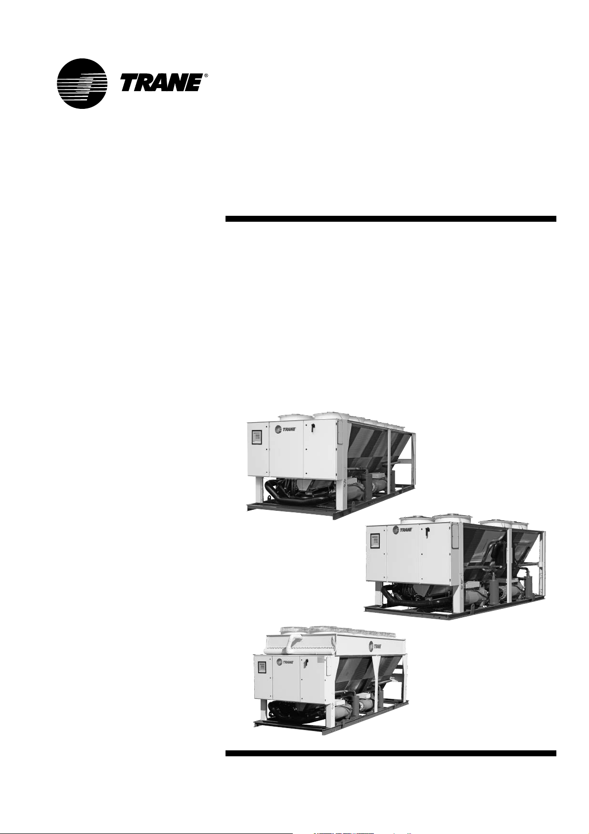
Series R™ Air-Cooled Helical Rotary
Liquid Chiller
RTAD 085 - 180 (50Hz)
Standard, Free Cooling and Heat
Recovery models
Page 2

RTAD-SVX01E-E4
©American Standard Inc. 2006
Foreword
These instructions are given as a
guide to good practice in the
installation, start-up, operation, and
maintenance by the user, of Trane
RTAD chillers. They do not contain
full service procedures necessary for
the continued successful operation of
this equipment. The services of a
qualified technician should be
employed through the medium of a
maintenance contract with a
reputable service company. Read
this manual thoroughly before unit
start-up.
Units are assembled, pressure
tested, dehydrated, charged and run
tested before shipment.
Warnings and cautions
Warnings and Cautions appear at
appropriate sections throughout this
manual. Your personal safety and the
proper operation of this machine
require that you follow them
carefully. The constructor assumes
no liability for installations or
servicing performed by unqualified
personnel.
WARNING! Indicates a potentially
hazardous situation which, if not
avoided, could result in death or
serious injury.
CAUTION! Indicates a potentially
hazardous situation which, if not
avoided, may result in minor or
moderate injury. It may also be used
to alert against unsafe practices or
for equipment or property-damageonly accidents.
Safety recommendations
To avoid death, injury, equipment or
property damage, the following
recommendations should be
observed during maintenance and
service visits:
1. The maximum allowable pressures
for system leak testing on low and
high pressure side are given in the
chapter "Installation". Always
provide a pressure regulator.
2. Disconnect the main power supply
before any servicing on the unit.
3. Service work on the refrigeration
system and the electrical system
should be carried out only by
qualified and experienced
personnel.
Reception
On arrival, inspect the unit before
signing the delivery note.
Reception in France only:
In case of visible damage: The
consignee (or the site representative)
must specify any damage on the
delivery note, legibly sign and date
the delivery note, and the truck
driver must countersign it. The
consignee (or the site representative)
must notify Trane Epinal Operations Claims team and send a copy of the
delivery note. The customer (or the
site representative) should send a
registered letter to the last carrier
within 3 days of delivery.
Note: for deliveries in France, even
concealed damage must be looked
for at deli
very and immediately
treated as visible damage.
General information
Page 3

RTAD-SVX01E-E4 3
General information
Reception in all countries except
France:
In case of concealed damage: The
consignee (or the site representative)
must send a registered letter to the
last carrier within 7 days of delivery,
claiming for the described damage. A
copy of this letter must be sent to
Trane Epinal Operations - Claims
team.
Warranty
Warranty is based on the general
terms and conditions of the
manufacturer. The warranty is void if
the equipment is repaired or
modified without the written
approval of the manufacturer, if the
operating limits are exceeded or if
the control system or the electrical
wiring is modified. Damage due to
misuse, lack of maintenance or
failure to comply with the
manufacturer's instructions or
recommendations is not covered by
the warranty obligation. If the user
does not conform to the rules of this
manual, it may entail cancellation of
warranty and liabilities by the
manufacturer.
Refrigerant
The refrigerant provided by the
manufacturer meets all the
requirements of our units. When
using recycled or reprocessed
refrigerant, it is advisable to ensure
its quality is equivalent to that of a
new refrigerant. For this, it is
necessary to have a precise analysis
made by a specialized laboratory. If
this condition is not respected, the
manufacturer warranty could be
cancelled.
Maintenance contract
It is strongly recommended that you
sign a maintenance contract with
your local Service Agency. This
contract provides regular
maintenance of your installation by
a specialist in our equipment.
Regular maintenance ensures that
any malfunction is detected and
corrected in good time and
minimizes the possibility that
serious damage will occur. Finally,
regular maintenance ensures the
maximum operating life of your
equipment. We would remind you
that failure to respect these
installation and maintenance
instructions may result in immediate
cancellation of the warranty.
Training
To assist you in obtaining the best
use of it and maintaining it in perfect
operating condition over a long
period of time, the manufacturer has
at your disposal a refrigeration and
air conditioning service school. The
principal aim of this is to give
operators and technicians a better
knowledge of the equipment they
are using, or that is under their
charge. Emphasis is particularly
given to the importance of periodic
checks on the unit operating
parameters as well as on preventive
maintenance, which reduces the cost
of owning the unit by avoiding
serious and costly breakdown.
Page 4

Contents
4 RTAD-SVX01E-E4
General Information 2
Unit Inspection 7
Loose Parts Inventory 7
General Data - Standard cooling unit 8
General Data - Free-cooling unit 16
General Data - Heat Recovery unit 18
Unit Dimensions 23
Installation - Mechanical 24
Installation Responsibilities 24
Nameplates 24
Storage 26
Location Requirements 26
Isolation and Sound Emission 26
Neoprene Isolator Installation 26
Noise Considerations 26
Foundation 27
Clearances 27
Drainage 28
Unit Water Piping 28
Unit Piping 28
Entering Chilled Water Piping 29
Leaving Chilled Water Piping 29
Heat Recovery Water Piping 29
Evaporator Drain 29
Evaporator Flow Switch 29
Water Treatment 30
Water Pressure Gauges 41
Water Pressure Relief Valves 41
Freeze Protection 41
Page 5
Installation - Electrical 42
General Recommendations 43
Installer-Supplied Components 48
Power Supply Wiring 48
Control Power Supply 48
Heater Power Supply 48
Water Pump Power Supply 48
Interconnecting Wiring 49
Chilled Water Flow (Pump) Interlock 49
Chilled Water Pump Control 49
Alarm and Status Relay Outputs
(Programmable Relays) 52
Low Voltage Wiring 54
External Emergency Stop 54
External Auto/Stop 54
External Circuit Lockout - Circuit 1 and Circuit 2 54
Ice Making Option 55
External Chilled Water Setpoint (CWS) 55
External Current Limit Setpoint (CLS) 56
Outdoor Air Temperature Sensor 56
Communication Card CSR 57
Communication link connection procedure 57
LonTalk communication interface 58
Operating Principles 64
System schematics 64
Pre-Start Checkout 67
Installation Checklist 67
Receiving 67
Unit Location and Mounting 67
Unit Piping 67
Electrical Wiring 67
General 68
Unit Voltage Power Supply 69
Unit Voltage Imbalance 69
Unit Voltage Phasing 69
Water System Flow Rates 70
Water System Pressure Drop 70
Contents
RTAD-SVX01E-E4 5
Page 6

6 RTAD-SVX01E-E4
Contents
Unit Start-up Procedures 71
Daily Unit Start-Up 71
General 72
Seasonal Unit Start-Up Procedure 73
System Restart After Extended Shutdown 73
Unit Shutdown Procedures 74
Temporary Shutdown And Restart 74
Extended Shutdown Procedure 74
Maintenance 75
General 75
Weekly Maintenance 75
Monthly Maintenance 75
Annual Maintenance 75
Maintenance Procedures 76
Refrigerant Emission Control 76
Refrigerant and Oil Charge Management 77
R134a Field Charging Procedure 77
Refrigerant Charging 77
Isolating the Refrigerant in the High Pressure Side 78
Isolating the Refrigerant in the Low Pressure Side 78
Adding Refrigerant 79
Refrigerant Filter Changing Procedure 79
Lubrication System 80
Oil Charging Procedure 80
Factory (initial) Oil Charging Procedure 81
Field Oil Charging Procedure 82
Evaporator Heat Tape Checkout Procedure 83
Safety recommendations 83
Page 7
RTAD-SVX01E-E4 7
General Information
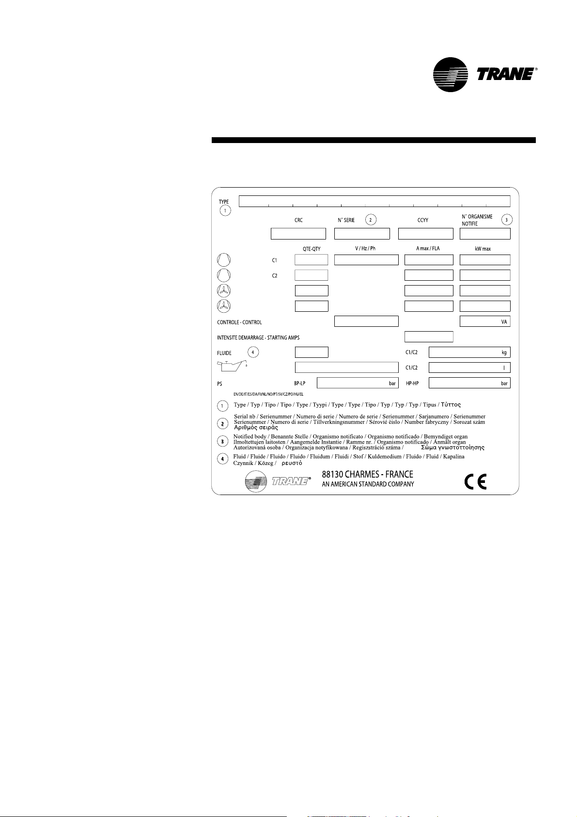
Unit Inspection
When the unit is delivered, verify
that it is the correct unit and that it is
properly equipped. Compare the
information which appears on the
unit nameplate with the ordering
and submittal information. A typical
unit nameplate is shown in Figure 1.
Loose Parts Inventory
Check all the accessories and loose
parts which are shipped with the
unit against the shipping list.
Included in these items will be water
vessel drain plugs, rigging and
electrical diagrams, and service
literature, which are placed inside
the control panel and/or starter
panel for shipment.
Figure 1 - Typical Unit Nameplate
Page 8

8 RTAD-SVX01E-E4
General Information
General Data - SI Units
Table 1 - General Data RTAD Standard
Size 085 100 115 125 145 150 165 180
Compressor Quantity 22222222
Nominal Size (1) (Tons) 40/40 50/50 60/60 70/70 85/70 85/85 100/85 100/100
Evaporator
Evaporator Model EG120 EG140 EG170 EG200 EG200 EG200 EG250 EG250
Water Storage (l) 106 270 222 204 204 204 415 415
Minimum Flow (l/s) 4.1 6.0 7.3 8.8 8.8 8.8 11.6 11.6
Maximum Flow (l/s) 17.3 20.8 24.8 30.7 30.7 30.7 38.0 38.0
Condenser
Qty of Coils 22222222
Coil Length (mm) 2743 3658 3658 3658 4572 4572 5486 5486
Coil Height (mm) 1626 1626 1626 1626 1626 1626 1626 1626
Fin series (Fins/ft) 192 192 192 192 192 192 192 192
Number of Rows 3/3 2/2 3/3 3/3 3/3 3/3 3/3 3/3
Condenser Fans
Quantity (1) 3/3 3/3 3/3 3/3 5/4 5/5 6/5 6/6
Diameter (mm) 762 762 762 762 762 762 762 762
Total Air Flow (m3/s) 23.4 28.5 27.0 27.0 37.0 39.0 44.9 46.8
Nominal RPM 915 915 915 915 915 915 915 915
Tip Speed (m/s) 36.5 36.5 36.5 36.5 36.5 36.5 36.5 36.5
Motor kW (kW) 2.05 2.05 2.05 2.05 2.05 2.05 2.05 2.05
Min Starting/Oper Ambient (2)
Standard Unit (°C) 00000000
Low Ambient Unit (°C) -18 -18 -18 -18 -18 -18 -18 -18
General Unit
Refrigerant HFC 134a HFC 134a HFC 134a HFC 134a HFC 134a HFC 134a HFC 134a HFC 134a
No. Of independent 22222222
Refrigerant Circuits
% Min. Load (3) 17 17 17 17 17 17 17 17
Refrigerant Charge (1) (kg) 24/24 30/32 35/36 36/37 44/48 44/48 61/59 61/61
Oil Charge (1) (l) 6/6 7/7 9/9 10/10 10/10 10/10 15/11 15/15
Operating Weight (4) (kg) 2660 3105 3555 3570 4260 4520 5440 5525
Shipping Weight (4) (kg) 2554 2838 3333 3368 4057 4317 5023 5108
Table 2 - General Data RTAD High Efficiency
Size 085 100 115 125 145 150
Compressor Quantity 222222
Nominal Size (1) (Tons) 40/40 50/50 60/60 70/70 85/70 85/85
Evaporator
Evaporator Model EG140 EG170 EG200 EG200 EG250 EG250
Water Storage (l) 270 222 204 204 415 415
Minimum Flow (l/s) 6.0 7.3 8.8 8.8 11.6 11.6
Maximum Flow (l/s) 20.8 24.8 30.7 30.7 38.0 38.0
Condenser
Qty of Coils 222222
Coil Length (mm) 3658 3658 4572 4572 5486 5486
Coil Height (mm) 1626 1626 1626 1626 1626 1626
Fin series (Fins/ft) 192 192 192 192 192 192
Number of Rows 3/3 3/3 3/3 3/3 3/3 3/3
Condenser Fans
Quantity (1) 3/3 4/4 4/4 5/5 6/5 6/6
Diameter (mm) 762 762 762 762 762 762
Total Air Flow (m3/s) 27.0 31.2 35.0 39.0 44.8 46.8
Nominal RPM 915 915 915 915 915 915
Tip Speed (m/s) 36.5 36.5 36.5 36.5 36.5 36.5
Motor kW (kW) 2.05 2.05 2.05 2.05 2.05 2.05
Min Starting/Oper Ambient (2)
Standard Unit (°C) 000000
Low Ambient Unit (°C) -18 -18 -18 -18 -18 -18
General Unit
Refrigerant HFC 134a HFC 134a HFC 134a HFC 134a HFC 134a HFC 134a
No. Of independent 222222
Refrigerant Circuits
% Min. Load (3) 17 17 17 17 17 17
Refrigerant Charge (1) (kg) 32/34 35/36 42/45 42/45 59/61 59/61
Oil Charge (1) (l) 6/6 7/7 10/10 10/10 11/11 11/11
Operating Weight (4) (kg) 3240 3370 3905 4000 5390 5445
Shipping Weight (4) (kg) 2973 3148 3702 3797 4973 5028
Notes:
(1) Data containing information on two circuits shown as follows: ckt1/ckt2
(2) Minimum start-up/operation ambient based on a 2.22 m/s (5mph) wind across the condenser.
(3) Percent minimum load is for total machine at 10°C (50F) ambient and 7°C (44F) leaving chilled water temp. Not each individual circuit
(4) Weights with aluminium fins, power disconnect switch, isolators and pressure gauges
Page 9

RTAD-SVX01E-E4 9
General Information
Table 3 - General Data RTAD Standard Low Noise
Size 085 100 115 125 145 150 165 180
Compressor Quantity 22222222
Nominal Size (1) (Tons) 40/40 50/50 60/60 70/70 85/70 85/85 100/85 100/100
Evaporator
Evaporator Model EG120 EG140 EG170 EG200 EG200 EG200 EG250 EG250
Water Storage (l) 106 270 222 204 204 204 415 415
Minimum Flow (l/s) 4.1 6.0 7.3 8.8 8.8 8.8 11.6 11.6
Maximum Flow (l/s) 17.3 20.8 24.8 30.7 30.7 30.7 38.0 38.0
Condenser
Qty of Coils 22222222
Coil Length (mm) 2743 3658 3658 3658 4572 4572 5486 5486
Coil Height (mm) 1626 1626 1626 1626 1626 1626 1626 1626
Fin series (Fins/ft) 192 192 192 192 192 192 192 192
Number of Rows 3/3 2/2 3/3 3/3 3/3 3/3 3/3 3/3
Condenser Fans
Quantity (1) 3/3 3/3 3/3 3/3 5/4 5/5 6/5 6/6
Diameter (mm) 762 762 762 762 762 762 762 762
Total Air Flow (m3/s) 18.1 22.4 21.0 21.0 28.7 30.1 34.7 36.2
Nominal RPM 730 730 730 730 730 730 730 730
Tip Speed (m/s) 29.1 29.1 29.1 29.1 29.1 29.1 29.1 29.1
Motor kW (kW) 1.30 1.30 1.30 1.30 1.30 1.30 1.30 1.30
Min Starting/Oper Ambient (2)
Standard Unit (°C) 00000000
Low Ambient Unit (°C) -18 -18 -18 -18 -18 -18 -18 -18
General Unit
Refrigerant HFC 134a HFC 134a HFC 134a HFC 134a HFC 134a HFC 134a HFC 134a HFC 134a
No. Of independent 22222222
Refrigerant Circuits
% Min. Load (3) 17 17 17 17 17 17 17 17
Refrigerant Charge (1) (kg) 24/24 30/32 35/36 36/37 44/48 44/48 61/59 61/61
Oil Charge (1) (l) 6/6 7/7 9/9 10/10 10/10 10/10 15/11 15/15
Operating Weight (4) (kg) 2760 3205 3655 3670 4360 4620 5540 5625
Shipping Weight (4) (kg) 2654 2938 3433 3468 4157 4417 5123 5208
Table 4 - General Data RTAD High Efficiency Low Noise
Size 085 100 115 125 145 150
Compressor Quantity 222222
Nominal Size (1) (Tons) 40/40 50/50 60/60 70/70 85/70 85/85
Evaporator
Evaporator Model EG140 EG170 EG200 EG200 EG250 EG250
Water Storage (l) 270 222 204 204 415 415
Minimum Flow (l/s) 6.0 7.3 8.8 8.8 11.6 11.6
Maximum Flow (l/s) 20.8 24.8 30.7 30.7 38.0 38.0
Condenser
Qty of Coils 222222
Coil Length (mm) 3658 3658 4572 4572 5486 5486
Coil Height (mm) 1626 1626 1626 1626 1626 1626
Fin series (Fins/ft) 192 192 192 192 192 192
Number of Rows 3/3 3/3 3/3 3/3 3/3 3/3
Condenser Fans
Quantity (1) 3/3 4/4 4/4 5/5 6/5 6/6
Diameter (mm) 762 762 762 762 762 762
Total Air Flow (m3/s) 21.0 24.1 27.2 30.1 34.7 36.1
Nominal RPM 690 690 690 690 690 690
Tip Speed (m/s) 27.5 27.5 27.5 27.5 27.5 27.5
Motor kW (kW) 1.30 1.30 1.30 1.30 1.30 1.30
Min Starting/Oper Ambient (2)
Standard Unit (°C) 000000
Low Ambient Unit (°C) -18 -18 -18 -18 -18 -18
General Unit
Refrigerant HFC 134a HFC 134a HFC 134a HFC 134a HFC 134a HFC 134a
No. Of independent 222222
Refrigerant Circuits
% Min. Load (3) 17 17 17 17 17 17
Refrigerant Charge (1) (kg) 32/34 35/36 42/45 42/45 59/61 59/61
Oil Charge (1) (l) 6/6 7/7 10/10 10/10 11/11 11/11
Operating Weight (4) (kg) 3340 3470 40 05 4100 5490 5545
Shipping Weight (4) (kg) 3073 3248 3802 3897 5073 5128
Notes:
(1) Data containing information on two circuits shown as follows: ckt1/ckt2
(2) Minimum start-up/operation ambient based on a 2.22 m/s (5mph) wind across the condenser.
(3) Percent minimum load is for total machine at 10°C (50F) ambient and 7°C (44F) leaving chilled water temp. Not each individual circuit
(4) Weights with aluminium fins, power disconnect switch, isolators and pressure gauges
Page 10

10 RTAD-SVX01E-E4
General Information
Table 5 - General Data RTAD Standard Low Noise with Night Noise Set Back option
Size 085 100 115 125 145 150 165 180
Compressor Quantity 22222222
Nominal Size (1) (Tons) 40/40 50/50 60/60 70/70 85/70 85/85 100/85 100/100
Evaporator
Evaporator Model EG120 EG140 EG170 EG200 EG200 EG200 EG250 EG250
Water Storage (l) 106 270 222 204 204 204 415 415
Minimum Flow (l/s) 4.1 6.0 7.3 8.8 8.8 8.8 11.6 11.6
Maximum Flow (l/s) 17.3 20.8 24.8 30.7 30.7 30.7 38.0 38.0
Condenser
Qty of Coils 22222222
Coil Length (mm) 2743 3658 3658 3658 4572 4572 5486 5486
Coil Height (mm) 1626 1626 1626 1626 1626 1626 1626 1626
Fin series (Fins/ft) 192 192 192 192 192 192 192 192
Number of Rows 3/3 2/2 3/3 3/3 3/3 3/3 3/3 3/3
Condenser Fans
Quantity (1) 2/2 3/3 3/3 3/3 4/4 4/4 5/5 5/5
Diameter (mm) 762 762 762 762 762 762 762 762
Total Air Flow (m3/s) 13.4 20.5 19.3 19.3 25.0 25.0 30.7 30.7
Nominal RPM 550 550 550 550 550 550 550 550
Tip Speed (m/s) 21.9 21.9 21.9 21.9 21.9 21.9 21.9 21.9
Motor kW (kW) 1.05 1.05 1.05 1.05 1.05 1.05 1.05 1.05
Min Starting/Oper Ambient (2)
Standard Unit (°C) 00000000
Low Ambient Unit (°C) -18 -18 -18 -18 -18 -18 -18 -18
General Unit
Refrigerant HFC 134a HFC 134a HFC 134a HFC 134a HFC 134a HFC 134a HFC 134a HFC 134a
No. Of independent 22222222
Refrigerant Circuits
% Min. Load (3) 17 17 17 17 17 17 17 17
Refrigerant Charge (1) (kg) 24/24 30/32 35/36 36/37 44/48 44/48 61/59 61/61
Oil Charge (1) (l) 6/6 7/7 9/9 10/10 10/10 10/10 15/11 15/15
Operating Weight (4) (kg) 2660 3205 3655 3670 4310 4520 5490 5525
Shipping Weight (4) (kg) 2554 2938 3433 3468 4107 4317 5073 5108
Table 6 - General Data RTAD High Efficiency Low Noise with Night Noise Set Back option
Size 085 100 115 125 145 150
Compressor Quantity 222222
Nominal Size (1) (Tons) 40/40 50/50 60/60 70/70 85/70 85/85
Evaporator
Evaporator Model EG140 EG170 EG200 EG200 EG250 EG250
Water Storage (l) 270 222 204 204 415 415
Minimum Flow (l/s) 6.0 7.3 8.8 8.8 11.6 11.6
Maximum Flow (l/s) 20.8 24.8 30.7 30.7 38.0 38.0
Condenser
Qty of Coils 222222
Coil Length (mm) 3658 3658 4572 4572 5486 5486
Coil Height (mm) 1626 1626 1626 1626 1626 1626
Fin series (Fins/ft) 192 192 192 192 192 192
Number of Rows 3/3 3/3 3/3 3/3 3/3 3/3
Condenser Fans
Quantity (1) 3/3 3/3 4/4 4/4 5/5 5/5
Diameter (mm) 762 762 762 762 762 762
Total Air Flow (m3/s) 19.2 19.2 24.9 25.0 30.6 30.6
Nominal RPM 550 550 550 550 550 550
Tip Speed (m/s) 21.9 21.9 21.9 21.9 21.9 21.9
Motor kW (kW) 1.05 1.05 1.05 1.05 1.05 1.05
Min Starting/Oper Ambient (2)
Standard Unit (°C) 000000
Low Ambient Unit (°C) -18 -18 -18 -18 -18 -18
General Unit
Refrigerant HFC 134a HFC 134a HFC 134a HFC 134a HFC 134a HFC 134a
No. Of independent 222222
Refrigerant Circuits
% Min. Load (3) 17 17 17 17 17 17
Refrigerant Charge (1) (kg) 32/34 35/36 42/45 42/45 59/61 59/61
Oil Charge (1) (l) 6/6 7/7 10/10 10/10 11/11 11/11
Operating Weight (4) (kg) 3340 3370 40 05 4000 5440 5445
Shipping Weight (4) (kg) 3073 3148 3802 3797 5023 5028
Notes:
(1) Data containing information on two circuits shown as follows: ckt1/ckt2
(2) Minimum start-up/operation ambient based on a 2.22 m/s (5mph) wind across the condenser.
(3) Percent minimum load is for total machine at 10°C (50F) ambient and 7°C (44F) leaving chilled water temp. Not each individual circuit
(4) Weights with aluminium fins, power disconnect switch, isolators and pressure gauges
Page 11

RTAD-SVX01E-E4 11
General Information
Table 7 - General Data RTAD Standard High External Static Pressure
Size 085 100 115 125 145 150 165 180
Compressor Quantity 22222222
Nominal Size (1) (Tons) 40/40 50/50 60/60 70/70 85/70 85/85 100/85 100/100
Evaporator
Evaporator Model EG120 EG140 EG170 EG200 EG200 EG200 EG250 EG250
Water Storage (l) 106 270 222 204 204 204 415 415
Minimum Flow (l/s) 4.1 6.0 7.3 8.8 8.8 8.8 11.6 11.6
Maximum Flow (l/s) 17.3 20.8 24.8 30.7 30.7 30.7 38.0 38.0
Condenser
Qty of Coils 22222222
Coil Length (mm) 2743 3658 3658 3658 4572 4572 5486 5486
Coil Height (mm) 1626 1626 1626 1626 1626 1626 1626 1626
Fin series (Fins/ft) 192 192 192 192 192 192 192 192
Number of Rows 3/3 2/2 3/3 3/3 3/3 3/3 3/3 3/3
Condenser Fans
Quantity (1) 3/3 3/3 3/3 3/3 5/4 5/5 6/5 6/6
Diameter (mm) 762 762 762 762 762 762 762 762
Total Air Flow (m3/s) 23.7 29.5 27.6 27.6 37.6 39.5 45.5 47.4
Nominal RPM 935 935 935 935 935 935 935 935
Tip Speed (m/s) 37.3 37.3 37.3 37.3 37.3 37.3 37.3 37.3
Motor kW (kW) 2.21 2.21 2.21 2.21 2.21 2.21 2.21 2.21
Min Starting/Oper Ambient (2)
Standard Unit (°C) 00000000
Low Ambient Unit (°C) -18 -18 -18 -18 -18 -18 -18 -18
General Unit
Refrigerant R134a R134a R134a R134a R134a R134a R134a R134a
No. Of independent 22222222
Refrigerant Circuits
% Min. Load (3) 17 17 17 17 17 17 17 17
Refrigerant Charge (1) (kg) 24/24 30/32 35/36 36/37 44/48 44/48 61/59 61/61
Oil Charge (1) (l) 6/6 7/7 9/9 10/10 10/10 10/10 15/11 15/15
Operating Weight (4) (kg) 2660 3105 3555 3570 4260 4520 5440 5525
Shipping Weight (4) (kg) 2554 2838 3333 3368 4057 4317 5023 5108
Table 8 - General Data RTAD High Efficiency High External Static Pressure
Size 085 100 115 125 145 150
Compressor Quantity 222222
Nominal Size (1) (Tons) 40/40 50/50 60/60 70/70 85/70 85/85
Evaporator
Evaporator Model EG140 EG170 EG200 EG200 EG250 EG250
Water Storage (l) 270 222 204 204 415 415
Minimum Flow (l/s) 6.0 7.3 8.8 8.8 11.6 11.6
Maximum Flow (l/s) 20.8 24.8 30.7 30.7 38.0 38.0
Condenser
Qty of Coils 222222
Coil Length (mm) 3658 3658 4572 4572 5486 5486
Coil Height (mm) 1626 1626 1626 1626 1626 1626
Fin series (Fins/ft) 192 192 192 192 192 192
Number of Rows 3/3 3/3 3/3 3/3 3/3 3/3
Condenser Fans
Quantity (1) 3/3 4/4 4/4 5/5 6/5 6/6
Diameter (mm) 762 762 762 762 762 762
Total Air Flow (m3/s) 27.6 31.5 35.6 39.4 45.4 47.3
Nominal RPM 935 935 935 935 935 935
Tip Speed (m/s) 37.3 37.3 37.3 37.3 37.3 37.3
Motor kW (kW) 2.21 2.21 2.21 2.21 2.21 2.21
Min Starting/Oper Ambient (2)
Standard Unit (°C) 000000
Low Ambient Unit (°C) -18 -18 -18 -18 -18 -18
General Unit
Refrigerant R134a R134a R134a R134a R134a R134a
No. Of independent 222222
Refrigerant Circuits
% Min. Load (3) 17 17 17 17 17 17
Refrigerant Charge (1) (kg) 32/34 35/36 42/45 42/45 59/61 59/61
Oil Charge (1) (l) 6/6 7/7 10/10 10/10 11/11 11/11
Operating Weight (4) (kg) 3240 3370 3905 4000 5390 5445
Shipping Weight (4) (kg) 2973 3148 3702 3797 4973 5028
Notes:
(1) Data containing information on two circuits shown as follows: ckt1/ckt2
(2) Minimum start-up/operation ambient based on a 2.22 m/s (5mph) wind across the condenser.
(3) Percent minimum load is for total machine at 10°C (50F) ambient and 7°C (44F) leaving chilled water temp. Not each individual circuit
(4) Weights with aluminium fins, power disconnect switch, isolators and pressure gauges
Page 12

12 RTAD-SVX01E-E4
General Information
English Units
Table 9 - General Data RTAD Standard
Size 085 100 115 125 145 150 165 180
Compressor Quantity 22222222
Nominal Size (1) (Tons) 40/40 50/50 60/60 70/70 85/70 85/85 100/85 100/100
Evaporator
Evaporator Model EG120 EG140 EG170 EG200 EG200 EG200 EG250 EG250
Water Storage (Gallon) 28.0 71.3 58.7 53.9 53.9 53.9 109.6 109.6
Minimum Flow (GPM) 65.2 95.1 115.0 139.2 139.2 139.2 184.0 184.0
Maximum Flow (GPM) 274.6 329.9 393.1 486.4 486.4 486.4 603.0 603.0
Condenser
Qty of Coils 22222222
Coil Length (inch) 108 144 144 144 180 180 216 216
Coil Height (inch) 64 64 64 64 64 64 64 64
Fin series (Fins/ft) 192 192 192 192 192 192 192 192
Number of Rows 3/3 2/2 3/3 3/3 3/3 3/3 3/3 3/3
Condenser Fans
Quantity (1) 3/3 3/3 3/3 3/3 5/4 5/5 6/5 6/6
Diameter (inch) 30 30 30 30 30 30 30 30
Total Air Flow (CFM) 49556 60460 57194 57248 78439 82716 95103 99250
Nominal RPM 915 915 915 915 915 915 915 915
Tip Speed (Ft/s) 119.8 119.8 119.8 119.8 119.8 119.8 119.8 119.8
Motor kW (kW) 2.05 2.05 2.05 2.05 2.05 2.05 2.05 2.05
Min Starting/Oper Ambient (2)
Standard Unit (°F) 32 32 32 32 32 32 32 32
Low Ambient Unit (°F) 00000000
General Unit
Refrigerant HFC 134a HFC 134a HFC 134a HFC 134a HFC 134a HFC 134a HFC 134a HFC 134a
No. Of independent 22222222
Refrigerant Circuits
% Min. Load (3) 17 17 17 17 17 17 17 17
Refrigerant Charge (1) (lbs.) 52.9/52.9 66.1/70.5 77.2/79.4 79.4/81.6 97/105.8 97/105.8 134.5/130.1 134.5/134.5
Oil Charge (1) (Gallon) 1.59/1.59 1.85/1.85 2.38/2.38 2.64/2.64 2.64/2.64 2.64/2.64 3.96/2.91 3.96/3.96
Operating Weight (4) (lbs.) 5864 6845 7837 7871 9392 9965 11993 12181
Shipping Weight (4) (lbs.) 5631 6257 7348 7425 8944 9517 11074 11261
Table 10 - General Data RTAD High Efficiency
Size 085 100 115 125 145 150
Compressor Quantity 222222
Nominal Size (1) (Tons) 40/40 50/50 60/60 70/70 85/70 85/85
Evaporator
Evaporator Model EG140 EG170 EG200 EG200 EG250 EG250
Water Storage (Gallon) 71.3 58.7 53.9 53.9 109.6 109.6
Minimum Flow (GPM) 95.1 115.0 139.2 139.2 184.0 184.0
Maximum Flow (GPM) 329.9 393.1 486.4 486.4 603.0 603.0
Condenser
Qty of Coils 222222
Coil Length (inch) 144 144 180 180 216 216
Coil Height (inch) 64 64 64 64 64 64
Fin series (Fins/ft) 192 192 192 192 192 192
Number of Rows 3/3 3/3 3/3 3/3 3/3 3/3
Condenser Fans
Quantity (1) 3/3 4/4 4/4 5/5 6/5 6/6
Diameter (inch) 30 30 30 30 30 30
Total Air Flow (CFM) 57108 66046 74100 82628 95008 99132
Nominal RPM 915 915 915 915 915 915
Tip Speed (Ft/s) 119.8 119.8 119.8 119.8 119.8 119.8
Motor kW (kW) 2.05 2.05 2.05 2.05 2.05 2.05
Min Starting/Oper Ambient (2)
Standard Unit (°F) 32 32 32 32 32 32
Low Ambient Unit (°F) 000000
General Unit
Refrigerant HFC 134a HFC 134a HFC 134a HFC 134a HFC 134a HFC 134a
No. Of independent 222222
Refrigerant Circuits
% Min. Load (3) 17 17 17 17 17 17
Refrigerant Charge (1) (lbs.) 70.5/75.0 77.2/79.4 92.6/99.2 92.6/99.2 130.1/134.5 130.1/134.5
Oil Charge (1) (Gallon) 1.59/1.59 1.85/1.85 2.64/2.64 2.64/2.64 2.91/2.91 2.91/2.91
Operating Weight (4) (lbs.) 7143 7430 8609 8818 11883 120 04
Shipping Weight (4) (lbs.) 6554 6940 8162 8371 10964 11085
Notes:
(1) Data containing information on two circuits shown as follows: ckt1/ckt2
(2) Minimum start-up/operation ambient based on a 2.22 m/s (5mph) wind across the condenser.
(3) Percent minimum load is for total machine at 10°C (50F) ambient and 7°C (44F) leaving chilled water temp. Not each individual circuit
(4) Weights with aluminium fins, power disconnect switch, isolators and pressure gauges
Page 13

RTAD-SVX01E-E4 13
General Information
Table 11 - General Data RTAD Standard Low Noise
Size 085 100 115 125 145 150 165 180
Compressor Quantity 22222222
Nominal Size (1) (Tons) 40/40 50/50 60/60 70/70 85/70 85/85 100/85 100/100
Evaporator
Evaporator Model EG120 EG140 EG170 EG200 EG200 EG200 EG250 EG250
Water Storage (Gallon) 28.0 71.3 58.7 53.9 53.9 53.9 109.6 109.6
Minimum Flow (GPM) 65.2 95.1 115.0 139.2 139.2 139.2 184.0 184.0
Maximum Flow (GPM) 274.6 329.9 393.1 486.4 486.4 486.4 603.0 603.0
Condenser
Qty of Coils 22222222
Coil Length (inch) 108 144 144 144 180 180 216 216
Coil Height (inch) 64 64 64 64 64 64 64 64
Fin series (Fins/ft) 192 192 192 192 192 192 192 192
Number of Rows 3/3 2/2 3/3 3/3 3/3 3/3 3/3 3/3
Condenser Fans
Quantity (1) 3/3 3/3 3/3 3/3 5/4 5/5 6/5 6/6
Diameter (inch) 30 30 30 30 30 30 30 30
Total Air Flow (CFM) 38246 47434 44514 44568 60751 63878 73628 76644
Nominal RPM 730 730 730 730 730 730 730 730
Tip Speed (Ft/s) 95.6 95.6 95.6 95.6 95.6 95.6 95.6 95.6
Motor kW (kW) 1.3 1.3 1.3 1.3 1.3 1.3 1.3 1.3
Min Starting/Oper Ambient (2)
Standard Unit (°F) 32 32 32 32 32 32 32 32
Low Ambient Unit (°F) 00000000
General Unit
Refrigerant HFC 134a HFC 134a HFC 134a HFC 134a HFC 134a HFC 134a HFC 134a HFC 134a
No. Of independent 22222222
Refrigerant Circuits
% Min. Load (3) 17 17 17 17 17 17 17 17
Refrigerant Charge (1) (Lbs.) 52.9/52.9 66.1/70.5 77.2/79.4 79.4/81.6 97/105.8 97/105.8 134.5/130.1 134.5/134.5
Oil Charge (1) (Gallon) 1.59/1.59 1.85/1.85 2.38/2.38 2.64/2.64 2.64/2.64 2.64/2.64 3.96/2.91 3.96/3.96
Operating Weight (4) (Lbs.) 6085 7066 8058 8091 9612 10185 12214 12401
Shipping Weight (4) (Lbs.) 5851 6477 7568 7646 9165 9738 11294 11482
Table 12 - General Data RTAD High Efficiency Low Noise
Size 085 100 115 125 145 150
Compressor Quantity 222222
Nominal Size (1) (Tons) 40/40 50/50 60/60 70/70 85/70 85/85
Evaporator
Evaporator Model EG140 EG170 EG200 EG200 EG250 EG250
Water Storage (Gallon) 71.3 58.7 53.9 53.9 109.6 109.6
Minimum Flow (GPM) 95.1 115.0 139.2 139.2 184.0 184.0
Maximum Flow (GPM) 329.9 393.1 486.4 486.4 603.0 603.0
Condenser
Qty of Coils 222222
Coil Length (inch) 144 144 180 180 216 216
Coil Height (inch) 64 64 64 64 64 64
Fin series (Fins/ft) 192 192 192 192 192 192
Number of Rows 3/3 3/3 3/3 3/3 3/3 3/3
Condenser Fans
Quantity (1) 3/3 4/4 4/4 5/5 6/5 6/6
Diameter (inch) 30 30 30 30 30 30
Total Air Flow (CFM) 44426 50964 57562 63784 73521 76510
Nominal RPM 690 690 690 690 690 690
Tip Speed (Ft/s) 90.3 90.3 90.3 90.3 90.3 90.3
Motor kW (kW) 1.3 1.3 1.3 1.3 1.3 1.3
Min Starting/Oper Ambient (2)
Standard Unit (°F) 32 32 32 32 32 32
Low Ambient Unit (°F) 000000
General Unit
Refrigerant HFC 134a HFC 134a HFC 134a HFC 134a HFC 134a HFC 134a
No. Of independent 222222
Refrigerant Circuits
% Min. Load (3) 17 17 17 17 17 17
Refrigerant Charge (1) (Lbs.) 70.5/75.0 77.2/79.4 92.6/99.2 92.6/99.2 130.1/134.5 130.1/134.5
Oil Charge (1) (Gallon) 1.59/1.59 1.85/1.85 2.64/2.64 2.64/2.64 2.91/2.91 2.91/2.91
Operating Weight (4) (Lbs.) 7363 7650 8830 9039 12103 12225
Shipping Weight (4) (Lbs.) 6775 7161 8382 8591 11184 11305
Notes:
(1) Data containing information on two circuits shown as follows: ckt1/ckt2
(2) Minimum start-up/operation ambient based on a 2.22 m/s (5mph) wind across the condenser.
(3) Percent minimum load is for total machine at 10°C (50F) ambient and 7°C (44F) leaving chilled water temp. Not each individual circuit
(4) Weights with aluminium fins, power disconnect switch, isolators and pressure gauges
Page 14
14 RTAD-SVX01E-E4
General Information
Table 13 - General Data RTAD Standard Low Noise with Night Noise Set Back option
Size 085 100 115 125 145 150 165 180
Compressor Quantity 22222222
Nominal Size (1) (Tons) 40/40 50/50 60/60 70/70 85/70 85/85 100/85 100/100
Evaporator
Evaporator Model EG120 EG140 EG170 EG200 EG200 EG200 EG250 EG250
Water Storage (Gallon) 28.0 71.3 58.7 53.9 53.9 53.9 109.6 109.6
Minimum Flow (GPM) 65.2 95.1 115.0 139.2 139.2 139.2 184.0 184.0
Maximum Flow (GPM) 274.6 329.9 393.1 486.4 486.4 486.4 603.0 603.0
Condenser
Qty of Coils 22222222
Coil Length (inch) 108 144 144 144 180 180 216 216
Coil Height (inch) 64 64 64 64 64 64 64 64
Fin series (Fins/ft) 192 192 192 192 192 192 192 192
Number of Rows 37318 37289 37318 37318 37318 37318 37318 37318
Condenser Fans
Quantity (1) 2/2 3/3 3/3 3/3 4/4 4/4 5/5 5/5
Diameter (inch) 30 30 30 30 30 30 30 30
Total Air Flow (CFM) 28479 43376 40791 40842 52929 52962 64956 65000
Nominal RPM 550 550 550 550 550 550 550 550
Tip Speed (Ft/s) 72.0 72.0 72.0 72.0 72.0 72.0 72.0 72.0
Motor kW (kW) 1.05 1.05 1.05 1.05 1.05 1.05 1.05 1.05
Min Starting/Oper Ambient (2)
Standard Unit (°F) 32 32 32 32 32 32 32 32
Low Ambient Unit (°F) 00000000
General Unit
Refrigerant HFC 134a HFC 134a HFC 134a HFC 134a HFC 134a HFC 134a HFC 134a HFC 134a
No. Of independent 22222222
Refrigerant Circuits
% Min. Load (3) 17 17 17 17 17 17 17 17
Refrigerant Charge (1) (lbs.) 52.9/52.9 66.1/70.5 77.2/79.4 79.4/81.6 97/105.8 97/105.8 134.5/130.1 134.5/134.5
Oil Charge (1) (Gallon) 1.59/1.59 1.85/1.85 2.38/2.38 2.64/2.64 2.64/2.64 2.64/2.64 3.96/2.91 3.96/3.96
Operating Weight (4) (lbs.) 5864 7066 8058 8091 9502 9965 12103 12181
Shipping Weight (4) (lbs.) 5631 6477 7568 7646 9054 9517 11184 11261
Table 14 - General Data RTAD High Efficiency Low Noise with with Night Noise Set Back option
Size 085 100 115 125 145 150
Compressor Quantity 222222
Nominal Size (1) (Tons) 40/40 50/50 60/60 70/70 85/70 85/85
Evaporator
Evaporator Model EG140 EG170 EG200 EG200 EG250 EG250
Water Storage (Gallon) 71.3 58.7 53.9 53.9 109.6 109.6
Minimum Flow (GPM) 95.1 115.0 139.2 139.2 184.0 184.0
Maximum Flow (GPM) 329.9 393.1 486.4 486.4 603.0 603.0
Condenser
Qty of Coils 222222
Coil Length (inch) 144 144 180 180 216 216
Coil Height (inch) 64 64 64 64 64 64
Fin series (Fins/ft) 192 192 192 192 192 192
Number of Rows 37318 37318 37318 37318 37318 37318
Condenser Fans
Quantity (1) 3/3 3/3 4/4 4/4 5/5 5/5
Diameter (inch) 30 30 30 30 30 30
Total Air Flow (CFM) 40710 40746 52846 52904 64872 64906
Nominal RPM 550 550 550 550 550 550
Tip Speed (Ft/s) 72.0 72.0 72.0 72.0 72.0 72.0
Motor kW (kW) 1.05 1.05 1.05 1.05 1.05 1.05
Min Starting/Oper Ambient (2)
Standard Unit (°F) 32 32 32 32 32 32
Low Ambient Unit (°F) 000000
General Unit
Refrigerant HFC 134a HFC 134a HFC 134a HFC 134a HFC 134a HFC 134a
No. Of independent 222222
Refrigerant Circuits
% Min. Load (3) 17 17 17 17 17 17
Refrigerant Charge (1) (lbs.) 70.5/75.0 77.2/79.4 92.6/99.2 92.6/99.2 130.1/134.5 130.1/134.5
Oil Charge (1) (Gallon) 1.59/1.59 1.85/1.85 2.64/2.64 2.64/2.64 2.91/2.91 2.91/2.91
Operating Weight (4) (lbs.) 7363 7430 8830 8818 11993 12004
Shipping Weight (4) (lbs.) 6775 6940 8382 8371 11074 11085
Notes:
(1) Data containing information on two circuits shown as follows: ckt1/ckt2
(2) Minimum start-up/operation ambient based on a 2.22 m/s (5mph) wind across the condenser.
(3) Percent minimum load is for total machine at 10°C (50F) ambient and 7°C (44F) leaving chilled water temp. Not each individual circuit
(4) Weights with aluminium fins, power disconnect switch, isolators and pressure gauges
Page 15
Table 15 - General Data RTAD Standard High External Static Pressure
Size 085 100 115 125 145 150 165 180
Compressor Quantity 22222222
Nominal Size (1) (Tons) 40/40 50/50 60/60 70/70 85/70 85/85 100/85 100/100
Evaporator
Evaporator Model EG120 EG140 EG170 EG200 EG200 EG200 EG250 EG250
Water Storage (Gallon) 28.0 71.3 58.7 53.9 53.9 53.9 109.6 109.6
Minimum Flow (GPM) 65.2 95.1 115.0 139.2 139.2 139.2 184.0 184.0
Maximum Flow (GPM) 274.6 329.9 393.1 486.4 486.4 486.4 603.0 603.0
Condenser
Qty of Coils 22222222
Coil Length (inch) 108 144 144 144 180 180 216 216
Coil Height (inch) 64 64 64 64 64 64 64 64
Fin series (Fins/ft) 192 192 192 192 192 192 192 192
Number of Rows 37683 37654 37683 37683 37683 37683 37683 37683
Condenser Fans
Quantity (1) 3/3 3/3 3/3 3/3 5/4 5/5 6/5 6/6
Diameter (inch) 30 30 30 30 30 30 30 30
Total Air Flow (CFM) 50118 62540 58514 58578 79569 83640 96363 100368
Nominal RPM 935 935 935 935 935 935 935 935
Tip Speed (Ft/s) 122.4 122.4 122.4 122.4 122.4 122.4 122.4 122.4
Motor kW (kW) 2.21 2.21 2.21 2.21 2.21 2.21 2.21 2.21
Min Starting/Oper Ambient (2)
Standard Unit (°F) 32 32 32 32 32 32 32 32
Low Ambient Unit (°F) 00000000
General Unit
Refrigerant R134a R134a R134a R134a R134a R134a R134a R134a
No. Of independent 22222222
Refrigerant Circuits
% Min. Load (3) 17 17 17 17 17 17 17 17
Refrigerant Charge (1) (lbs.) 52.9/52.9 66.1/70.5 77.2/79.4 79.4/81.6 97/105.8 97/105.8 134.5/130.1 134.5/134.5
Oil Charge (1) (Gallon) 1.59/1.59 1.85/1.85 2.38/2.38 2.64/2.64 2.64/2.64 2.64/2.64 3.96/2.91 3.96/3.96
Operating Weight (4) (lbs.) 5864 6845 7837 7871 9392 9965 11993 12181
Shipping Weight (4) (lbs.) 5631 6257 7348 7425 8944 9517 11074 11261
Table 16 - General Data RTAD High Efficiency High External Static Pressure
Size 085 100 115 125 145 150
Compressor Quantity 222222
Nominal Size (1) (Tons) 40/40 50/50 60/60 70/70 85/70 85/85
Evaporator
Evaporator Model EG140 EG170 EG200 EG200 EG250 EG250
Water Storage (Gallon) 71.3 58.7 53.9 53.9 109.6 109.6
Minimum Flow (GPM) 95.1 115.0 139.2 139.2 184.0 184.0
Maximum Flow (GPM) 329.9 393.1 486.4 486.4 603.0 603.0
Condenser
Qty of Coils 222222
Coil Length (inch) 144 144 180 180 216 216
Coil Height (inch) 64 64 64 64 64 64
Fin series (Fins/ft) 192 192 192 192 192 192
Number of Rows 37683 37683 37683 37683 37683 37683
Condenser Fans
Quantity (1) 3/3 4/4 4/4 5/5 6/5 6/6
Diameter (inch) 30 30 30 30 30 30
Total Air Flow (CFM) 58412 66796 75432 83562 96257 100248
Nominal RPM 935 935 935 935 935 935
Tip Speed (Ft/s) 122.4 122.4 122.4 122.4 122.4 122.4
Motor kW (kW) 2.21 2.21 2.21 2.21 2.21 2.21
Min Starting/Oper Ambient (2)
Standard Unit (°F) 32 32 32 32 32 32
Low Ambient Unit (°F) 000000
General Unit
Refrigerant R134a R134a R134a R134a R134a R134a
No. Of independent 222222
Refrigerant Circuits
% Min. Load (3) 17 17 17 17 17 17
Refrigerant Charge (1) (Lbs.) 70.5/75.0 77.2/79.4 92.6/99.2 92.6/99.2 130.1/134.5 130.1/134.5
Oil Charge (1) (Gallon) 1.59/1.59 1.85/1.85 2.64/2.64 2.64/2.64 2.91/2.91 2.91/2.91
Operating Weight (4) (Lbs.) 7143 7430 8609 8818 11883 120 04
Shipping Weight (4) (Lbs.) 6554 6940 8162 8371 10964 11085
Notes:
(1) Data containing information on two circuits shown as follows: ckt1/ckt2
(2) Minimum start-up/operation ambient based on a 2.22 m/s (5mph) wind across the condenser.
(3) Percent minimum load is for total machine at 10°C (50F) ambient and 7°C (44F) leaving chilled water temp. Not each individual circuit.
(4) Weights with aluminium fins, power disconnect switch, isolators and pressure gauges
RTAD-SVX01E-E4 15
General Information
Page 16

16 RTAD-SVX01E-E4
General Information
Table 17 - General Data RTAD FC Standard
Unit Size 085 100 115 125 145 150 165 180
Number of Compressors 22222222
Nominal Size (1) (Tons) 40/40 50/50 60/60 70/70 85/70 85/85 100/85 100/100
Evaporator
Evaporator Model EG120 EG140 EG170 EG200 EG200 EG200 EG250 EG250
Water Storage (l) 106 270 222 204 204 204 415 415
Minimum Flow (l/s) 4.1 6 7.3 8.8 8.8 8.8 11.6 11.6
Maximum Flow (l/s) 17.3 20.8 24.8 30.7 30.7 30.7 38 38
Free-Cooler
Number of Coils 11111111
Fin series (Fins/ft) 152 152 122 122 152 152 152 152
Number of Rows 44665555
Water Storage (l) 265 481 538 520 531 531 806 806
(Evap+Free-Cooler)
Condenser
Number of Coils 22222222
Fin series (Fins/ft) 192 192 192 192 192 192 192 192
Number of Rows 3/3 2/2 3/3 3/3 3/3 3/3 3/3 3/3
Condenser Fans
Quantity (1) 3/3 3/3 3/3 4/4 5/4 5/5 6/5 6/6
Diameter (mm) 762 762 762 762 762 762 762 762
Total Air Flow (m3/s) 17.9/13.0 21.6/15.7 20.4/14.7 23.5/17.2 28.4/20.6 29/21.2 34.2/24.8 34.7/25.4
Nominal Speed (rpm) 935/740 935/740 935/740 935/740 935/740 935/740 935/740 935/740
Motor kW (kW) 1.7/0.85 1.7/0.85 1.7/0.85 1.7/0.85 1.7/0.85 1.7/0.85 1.7/0.85 1.7/0.85
Min Starting/ (°C) -18 -18 -18 -18 -18 -18 -18 -18
Oper Ambient(2)
General Unit
Refrigerant HFC 134a HFC 134a HFC 134a HFC 134a HFC 134a HFC 134a HFC 134a HFC 134a
No. Of independent 22222222
Refrigerant Circuits
% Min. Load (3) 17 17 17 17 17 17 17 17
Weight. Capacities & Dimensions
Refrigerant Charge (1) (kg) 24/24 30/32 35/36 36/37 44/48 44/48 61/59 61/61
Oil Charge (1) (l) 6/6 7/7 9/9 10/10 10/10 10/10 15/11 15/15
Operating Weight (4) (kg) 3685 4492 5291 5446 6296 6241 7884 7969
Shipping Weight (4) (kg) 3300 3740 4530 4720 5560 5505 6665 6750
Length (mm) 3900 4850 4850 4850 5770 5770 6810 6810
Width (mm) 2420 2420 2420 2420 2420 2420 2460 2460
Height (mm) 2605 2605 2605 2605 2645 2645 2745 2745
Water Connection (mm) 139.7 139.7 139.7 139.7 139.7 139.7 168.3 168.3
Diameter
Water Connection Type Victaulic Victaulic Victaulic Victaulic Victaulic Victaulic Victaulic Victaulic
(1) Data containing information on two circuits shown as follows: ckt1/ckt2
(2) Minimum start-up/operation ambient based on a 2.22 m/s wind across the condenser
(3) Percent minimum load is for total machine at 10°C ambient and 7°C leaving chilled water temp. Not each individual circuit.
(4) Weights with aluminium fins, power disconnect switch, isolators and pressure gauges
Note:
All Free Cooling units must be freeze protected with 30% Ethylene Glycol in the cooling loop circuit which is the most convenient percentage in order
to protect the unit against freezing.
Protection coverage with 30% Ethylene Glycol:
- freezing point without burst effect = -13°C;
- freezing point with burst effect = -50°C.
Page 17
RTAD-SVX01E-E4 17
General Information
Table 18 - General Data RTAD FC High Efficiency
Unit Size 085 100 115 125 145 150
Number of Compressors 222222
Nominal Size (1) (Tons) 40/40 50/50 60/60 70/70 85/70 85/85
Evaporator
Evaporator Model EG 140 EG 170 EG 200 EG 200 EG 250 EG 250
Water Storage (l) 270 222 204 204 415 415
Minimum Flow (l/s) 6 7.3 8.8 8.8 11.6 11.6
Maximum Flow (l/s) 20.8 24.8 30.7 30.7 38 38
Free-Cooler
Number of Coils 111111
Fin series (Fins/ft) 152 122 152 152 152 152
Number of Rows 465555
Water Storage (l) 481 538 531 531 806 806
(Evap+Free-Cooler)
Condenser
Number of Coils 222222
Fin series (Fins/ft) 192 192 192 192 192 192
Number of Rows 3/3 3/3 3/3 3/3 3/3 3/3
Condenser Fans
Quantity (1) 3/3 4/4 4/4 5/5 6/5 6/6
Diameter (mm) 762 762 762 762 762 762
Total Air Flow (m3/s) 20.8/15.1 23.5/17.2 26/18.9 28.9/21.2 34.1/24.8 34.7/25.4
Nominal Speed (rpm) 935/740 935/740 935/740 935/740 935/740 935/740
Motor kW (kW) 1.7/0.85 1.7/0.85 1.7/0.85 1.7/0.85 1.7/0.85 1.7/0.85
Min Starting/ (°C) -18 -18 -18 -18 -18 -18
Oper Ambient (2)
General Unit
Refrigerant HFC 134a HFC 134a HFC 134a HFC 134a HFC 134a HFC 134a
No. Of independent 222222
Refrigerant Circuits
% Min. Load (3) 17 17 17 17 17 17
Weight. Capacities & Dimensions
Refrigerant Charge (1) (kg) 32/34 35/36 42/45 42/45 59/61 59/61
Oil Charge (1) (l) 6/6 7/7 10/10 10/10 11/11 11/11
Operating Weight (4) (kg) 4627 5106 5905 6000 7834 7889
Shipping Weight (4) (kg) 3875 4345 5170 5265 6615 6670
Length (mm) 4850 4850 5770 5770 6810 6810
Width (mm) 2420 2420 2420 2420 2460 2460
Height (mm) 2605 2605 2645 2645 2745 2745
Water Connection (mm) 139.7 139.7 139.7 139.7 168.3 168.3
Diameter
Water Connection Type Victaulic Victaulic Victaulic Victaulic Victaulic Victaulic
(1) Data containing information on two circuits shown as follows: ckt1/ckt2
(2) Minimum start-up/operation ambient based on a 2.22 m/s wind across the condenser
(3) Percent minimum load is for total machine at 10°C ambient and 7°C leaving chilled water temp. Not each individual circuit.
(4) Weights with aluminium fins, power disconnect switch, isolators and pressure gauges
Page 18

18 RTAD-SVX01E-E4
General Information
Table 19 - General Data RTAD Heat Recovery Standard
Unit Size 085 100 115 125 145 150 165 180
Number of Compressors 22222222
Nominal Size (1) (Tons) 40/40 50/50 60/60 70/70 85/70 85/85 100/85 100/100
Evaporator
Evaporator Model EG120 EG140 EG170 EG200 EG200 EG200 EG250 EG250
Water Storage (l) 106 269 223 204 204 204 415 415
Minimum Flow (l/s) 4.1 6 7.3 8.8 8.8 8.8 11.6 11.6
Maximum Flow (l/s) 17.3 20.8 24.8 30.7 30.7 30.7 38.0 38.0
Water Connection Type Victaulic
Water Connection (inch-mm) 6" - 168.3 6" - 168.3 6" - 168.3 6" - 168.3 6" - 168.3 6" - 168.3 6" - 168.3
Diameter
Heat Recovery Heat-Exchanger
Type Brazed Plates
Water connection type Victaulic
PHR
Connection diameter (inch-mm) 2" - 60.3 2" - 60.3 2" - 60.3 2" - 60.3 2" - 60.3 2" - 60.3 2" - 60.3 2" - 60.3
Water Storage capacity (l) 8 8 9 9 11 11 12 12
THR
Connection diameter (inch-mm) -
2" - 60.3 2" - 60.3 2" - 60.3 3" O.D. - 3" O.D. - 3" O.D. - 3" O.D. -
76.1 76.1 76.1 76.1
Water Storage capacity (l) - 10 14 14 16 16 19 19
Condenser
Number of Coils 22222222
Fin series (Fins/ft) 192 192 192 192 192 192 192 192
Number of Rows 3/3 2/2 3/3 3/3 3/3 3/3 3/3 3/3
Condenser Fans
Quantity (1) 3/3 3/3 3/3 3/3 5/4 5/5 6/5 6/6
Diameter (mm) 762 762 762 762 762 762 762 762
Total Air Flow (m3/s) 23.4 28.5 27.0 27.0 37.0 39.0 44.9 46.8
Nominal Speed (rpm) 930 930 930 930 930 930 930 930
Motor kW (kW) 1.72 1.72 1.72 1.72 1.72 1.72 1.72 1.72
Min Starting/Oper Ambient (2)
PHR (°C)00000000
THR (°C) -18 -18 -18 -18 -18 -18 -18 -18
General Unit
Refrigerant HFC 134a HFC 134a HFC 134a HFC 134a HFC 134a HFC 134a HFC 134a HFC 134a
No. Of independent 22222222
Refrigerant Circuits
% Min. Load (3) 17 17 17 17 17 17 17 17
Weight. Capacities & Dimensions
PHR
Refrigerant Charge (1) (kg) 26/26 33/35 38/39 39/40 47/51 47/51 65/63 65/65
Oil Charge (1) (l) 6/6 7/7 9/9 10/10 10/10 10/10 15/11 15/15
Operating Weight (4) (kg) 2736 3176 3635 3650 4345 4605 5535 5622
Shipping Weight (4) (kg) 2622 2899 3403 3437 4130 4390 5108 5195
THR
Refrigerant Charge (1) (kg) - 55 / 52 67 / 64 68 / 64 86 / 84 86 / 84 100 / 95 100 / 98
Oil Charge (1) (l) - 5 / 4 8 / 7 8 / 7 8 / 7 8 / 7 13 / 7 13 / 12
Operating Weight (4) (kg) - 3347 3833 3848 4615 4875 5806 5891
Shipping Weight (4) (kg) - 3061 3589 3623 4382 4642 5359 5444
Dimensions
Length (mm) 3507 4426 4426 4426 5351 5351 6370 6370
Width (mm) 2260 2260 2260 2260 2260 2260 2260 2260
Height (mm) 2095 2095 2095 2095 2115 2115 2215 2215
(1) Data containing information on two circuits shown as follows: ckt1/ckt2
(2) Minimum start-up/operation ambient based on a 2.22 m/s wind across the condenser.
(3) Percent minimum load is for total machine at 10°C ambient and 7°C leaving chilled water temp. Not each individual circuit.
(4) With aluminum fins
5"1/2 O.D.-
139.7
Page 19
RTAD-SVX01E-E4 19
General Information
Table 20 - General Data RTAD Heat Recovery High Efficiency
Unit Size 085 100 115 125 145 150
Number of Compressors 222222
Nominal Size (1) (Tons) 40/40 50/50 60/60 70/70 85/70 85/85
Evaporator
Evaporator Model EG140 EG170 EG200 EG200 EG250 EG250
Water Storage (l) 269 223 204 204 415 415
Minimum Flow (l/s) 6 7.3 8.8 8.8 11.6 11.6
Maximum Flow l/s) 20.8 24.8 30.7 30.7 38.0 38.0
Water Connection Type Victaulic
Water Connection (inch-mm) 6" - 168.3 6" - 168.3 6" - 168.3 6" - 168.3 6" - 168.3 6" - 168.3
Diameter
Heat Recovery Heat-Exchanger
Type Brazed Plates
Water connection type Victaulic
PHR
Connection diameter (inch-mm) 2" - 60.3 2" - 60.3 2" - 60.3 2" - 60.3 2" - 60.3 2" - 60.3
Water Storage capacity (l) 88991111
THR
Connection diameter (inch-mm) 2" - 60.3 2" - 60.3 2" - 60.3 2" - 60.3 3" O.D. - 76.1 3" O.D. - 76.1
Water Storage capacity (l) 10 10 14 14 16 16
Condenser
Number of Coils 222222
Fin series (Fins/ft) 192 192 192 192 192 192
Number of Rows 3/3 3/3 3/3 3/3 3/3 3/3
Condenser Fans
Quantity (1) 3/3 4/4 4/4 5/5 6/5 6/6
Diameter (mm) 762 762 762 762 762 762
Total Air Flow (m3/s) 27.0 31.2 35.0 39.0 44.9 46.8
Nominal Speed (rpm) 930 930 930 930 930 930
Motor kW (kW) 1.72 1.72 1.72 1.72 1.72 1.72
Min Starting/Oper Ambient (2)
PHR (°C) 000000
THR (°C) -18 -18 -18 -18 -18 -18
General Unit
Refrigerant HFC 134a HFC 134a HFC 134a HFC 134a HFC 134a HFC 134a
No. Of independent 222222
Refrigerant Circuits
% Min. Load (3) 17 17 17 17 17 17
Weight. Capacities & Dimensions
PHR
Refrigerant Charge (1) (kg) 35/37 38/39 45/48 45/48 63/65 63/65
Oil Charge (1) (l) 6/6 7/7 10/10 10/10 11/11 11/11
Operating Weight (4) (kg) 3311 3441 3984 4079 5474 5529
Shipping Weight (4) (kg) 2375 2504 3045 3140 4532 4587
THR
Refrigerant Charge (1) (kg) 63 / 60 65 / 62 86 / 84 86 / 84 97 / 95 97 / 95
Oil Charge (1) (l) 5 / 4 5 / 4 8 / 7 8 / 7 8 / 7 8 / 7
Operating Weight (4) (kg) 3494 3624 4238 4333 5731 5786
Shipping Weight (4) (kg) 3208 3384 4013 4108 5287 5342
Dimensions
Length (mm) 4426 4426 5351 5351 6370 6370
Width (mm) 2260 2260 2260 2260 2260 2260
Height (mm) 2095 2095 2115 2115 2215 2215
(1) Data containing information on two circuits shown as follows: ckt1/ckt2
(2) Minimum start-up/operation ambient based on a 2.22 m/s wind across the condenser.
(3) Percent minimum load is for total machine at 10°C ambient and 7°C leaving chilled water temp. Not each individual circuit.
(4) With aluminum fins
Page 20
20 RTAD-SVX01E-E4
General Information
Table 21 - General Data RTAD Heat Recovery Standard Low Noise
Unit Size 085 100 115 125 145 150 165 180
Number of Compressors 22222222
Nominal Size (1) (Tons) 40/40 50/50 60/60 70/70 85/70 85/85 100/85 100/100
Evaporator
Evaporator Model EG120 EG140 EG170 EG200 EG200 EG200 EG250 EG250
Water Storage (l) 106 269 223 204 204 204 415 415
Minimum Flow (l/s) 4.1 6 7.3 8.8 8.8 8.8 11.6 11.6
Maximum Flow (l/s) 17.3 20.8 24.8 30.7 30.7 30.7 38.0 38.0
Water Connection Type Victaulic
Water Connection (inch-mm) 6" - 168.3 6" - 168.3 6" - 168.3 6" - 168.3 6" - 168.3 6" - 168.3 6" - 168.3
Diameter
Heat Recovery Heat-Exchanger
Type Brazed Plates
Water connection type Victaulic
PHR
Connection diameter (inch-mm) 2" - 60.3 2" - 60.3 2" - 60.3 2" - 60.3 2" - 60.3 2" - 60.3 2" - 60.3 2" - 60.3
Water Storage capacity (l) 889911111212
THR
Connection diameter (inch-mm) -
2" - 60.3 2" - 60.3 2" - 60.3 3" O.D. - 3" O.D. - 3" O.D. - 3" O.D. -
76.1 76.1 76.1 76.1
Water Storage capacity (l) - 10 14 14 16 16 19 19
Condenser
Number of Coils 22222222
Fin series (Fins/ft) 192 192 192 192 192 192 192 192
Number of Rows 3/3 2/2 3/3 3/3 3/3 3/3 3/3 3/3
Condenser Fans
Quantity (1) 3/3 3/3 3/3 3/3 5/4 5/5 6/5 6/6
Diameter (mm) 762 762 762 762 762 762 762 762
Total Air Flow (m3/s) 18.1 22.4 21.0 21.0 28.7 30.1 34.7 36.2
Nominal Speed (rpm) 750 750 750 750 750 750 750 750
Motor kW (kW) 1.23 1.23 1.23 1.23 1.23 1.23 1.23 1.23
Min Starting/Oper Ambient (2)
PHR (°C)00000000
THR (°C) -18 -18 -18 -18 -18 -18 -18 -18
General Unit
Refrigerant HFC 134a HFC 134a HFC 134a HFC 134a HFC 134a HFC 134a HFC 134a HFC 134a
No. Of independent 22222222
Refrigerant Circuits
% Min. Load (3) 17 17 17 17 17 17 17 17
Weight. Capacities & Dimensions
PHR
Refrigerant Charge (1) (kg) 26/26 33/35 38/39 39/40 47/51 47/51 65/63 65/65
Oil Charge (1) (l) 6/6 7/7 9/9 10/10 10/10 10/10 15/11 15/15
Operating Weight (4) (kg) 2836 3276 3735 3750 4445 4705 5635 5722
Shipping Weight (4) (kg) 2082 2520 2978 2991 3686 3946 4873 4960
THR
Refrigerant Charge (1) (kg) - 55 / 52 67 / 64 68 / 64 86 / 84 86 / 84 100 / 95 100 / 98
Oil Charge (1) (l) - 5 / 4 8 / 7 8 / 7 8 / 7 8 / 7 13 / 7 13 / 12
Operating Weight (4) (kg) - 3447 3933 3948 4715 4975 5906 5991
Shipping Weight (4) (kg) - 3161 3689 3723 4482 4742 5459 5544
Dimensions
Length (mm) 3507 4426 4426 4426 5351 5351 6370 6370
Width (mm) 2260 2260 2260 2260 2260 2260 2260 2260
Height (mm) 2095 2095 2095 2095 2115 2115 2215 2215
(1) Data containing information on two circuits shown as follows: ckt1/ckt2
(2) Minimum start-up/operation ambient based on a 2.22 m/s wind across the condenser.
(3) Percent minimum load is for total machine at 10°C ambient and 7°C leaving chilled water temp. Not each individual circuit.
(4) With aluminum fins
5"1/2 O.D.-
139.7
Page 21

Table 22 - General Data RTAD Heat Recovery High Efficiency Low Noise
Unit Size 085 100 115 125 145 150
Number of Compressors 222222
Nominal Size (1) (Tons) 40/40 50/50 60/60 70/70 85/70 85/85
Evaporator
Evaporator Model EG140 EG170 EG200 EG200 EG250 EG250
Water Storage (l) 269 223 204 204 415 415
Minimum Flow (l/s) 6 7.3 8.8 8.8 11.6 11.6
Maximum Flow l/s) 20.8 24.8 30.7 30.7 38 38
Water Connection Type Victaulic
Water Connection (inch-mm) 6" - 168.3 6" - 168.3 6" - 168.3 6" - 168.3 6" - 168.3 6" - 168.3
Diameter
Heat Recovery Heat-Exchanger
Type Brazed Plates
Water connection type Victaulic
PHR
Connection diameter 2" - 60.3 2" - 60.3 2" - 60.3 2" - 60.3 2" - 60.3 2" - 60.3
Water Storage capacity (l) 88991111
THR
Connection diameter (inch-mm) 2" - 60.3 2" - 60.3 2" - 60.3 2" - 60.3 3" O.D. - 76.1 3" O.D. - 76.1
Water Storage capacity (l) 10 10 14 14 16 16
Condenser
Number of Coils 222222
Fin series (Fins/ft) 192 192 192 192 192 192
Number of Rows 3/3 3/3 3/3 3/3 3/3 3/3
Condenser Fans
Quantity (1) 3/3 4/4 4/4 5/5 6/5 6/6
Diameter (mm) 762 762 762 762 762 762
Total Air Flow (m3/s) 21.0 24.1 27.2 30.1 34.7 36.2
Nominal Speed (rpm) 750 750 750 750 750 750
Motor kW (kW) 1.23 1.23 1.23 1.23 1.23 1.23
Min Starting/Oper Ambient (2)
PHR (°C) 000000
THR (°C) -18 -18 -18 -18 -18 -18
General Unit
Refrigerant HFC 134a HFC 134a HFC 134a HFC 134a HFC 134a HFC 134a
No. Of independent 222222
Refrigerant Circuits
% Min. Load (3) 17 17 17 17 17 17
Weight. Capacities & Dimensions
PHR
Refrigerant Charge (1) (kg) 35/37 38/39 45/48 45/48 63/65 63/65
Oil Charge (1) (l) 6/6 7/7 10/10 10/10 11/11 11/11
Operating Weight (4) (kg) 3411 3541 4084 4179 5574 5629
Shipping Weight (4) (kg) 2655 2784 3325 3420 4812 4867
THR
Refrigerant Charge (1) (kg) 63 / 60 65 / 62 86 / 84 86 / 84 97 / 95 97 / 95
Oil Charge (1) (l) 5 / 4 5 / 4 8 / 7 8 / 7 8 / 7 8 / 7
Operating Weight (4) (kg) 3594 3724 4338 4433 5831 5886
Shipping Weight (4) (kg) 3308 3484 4113 4208 5387 5442
Dimensions
Length (mm) 4426 4426 5351 5351 6370 6370
Width (mm) 2260 2260 2260 2260 2260 2260
Height (mm) 2095 2095 2115 2115 2215 2215
(1) Data containing information on two circuits shown as follows: ckt1/ckt2
(2) Minimum start-up/operation ambient based on a 2.22 m/s wind across the condenser.
(3) Percent minimum load is for total machine at 10°C ambient and 7°C leaving chilled water temp. Not each individual circuit.
(4) With aluminum fins
RTAD-SVX01E-E4 21RTAD-SVX01E-E4 21
General Information
Page 22
22 RTAD-SVX01E-E4
General Information
The below hydraulic module operating weight must be added to the RTAD operating
weight.
Table 23 - Hydraulic module additional operating weight - SI units (kg)
RTAD 115 HE - RTAD 125 HE RTAD 145 SE - RTAD 150 SE Expansion vessel
Pump type Pump model Without 50 litres 80 litres
LRN 208-13/5.5 - LRN 208-14/7.5 400 460 500
SIL 208-16/11 - SIL 208-17/15 455 515 555
JRN 208-13/5.5 - JRN 208-14/7.5 490 550 590
SIL 208-16/11 - SIL 208-17/15 600 660 700
RTAD 145 HE - RTAD 150 HE RTAD 165 SE - RTAD 180 HE Expansion vessel
LRN 208-13/5.5 - LRN 208-14/7.5 510 570 610
SIL 208-16/11 - SIL 208-17/15 565 625 665
JRN 208-13/5.5 - JRN 208-14/7.5 600 660 700
SIL 208-16/11 - SIL 208-17/15 710 770 810
Hydraulic module addtional operating weight - English units (lbs)
RTAD 115 HE - RTAD 125 HE RTAD 145 SE - RTAD 150 SE Expansion vessel
Pump type Pump model Without 50 litres 80 litres
LRN 208-13/5.5 - LRN 208-14/7.5 882 1014 1102
SIL 208-16/11 - SIL 208-17/15 1003 1135 1224
JRN 208-13/5.5 - JRN 208-14/7.5 1080 1213 1301
SIL 208-16/11 - SIL 208-17/15 1323 1455 1543
RTAD 145 HE - RTAD 150 HE RTAD 165 SE - RTAD 180 HE Expansion vessel
LRN 208-13/5.5 - LRN 208-14/7.5 1124 1257 1345
SIL 208-16/11 - SIL 208-17/15 1246 1378 1466
JRN 208-13/5.5 - JRN 208-14/7.5 1323 1455 1543
SIL 208-16/11 - SIL 208-17/15 1565 1698 1786
Single
Single
Dual
Dual
Single
Single
Dual
Dual
Page 23
RTAD-SVX01E-E4 23
General Information
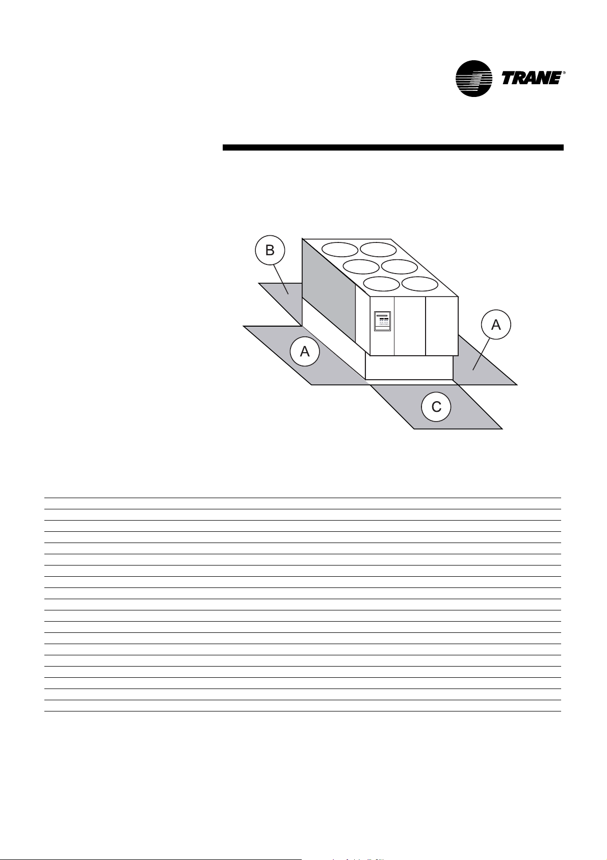
Unit Dimensions
Figure 2 - Unit Dimensions and Minimum Recommended Clearances
Table 24
Note: Size 085 does not exist for Total Heat Recovery option but HE version is available
Unit Dimensions (mm) Minimum clearances (mm)
Length Width Height A B C
Unit Size
Standard, Partial Heat Recovery, and Total Heat Recovery
RTAD 085 3507 2260 2095 1200 1000 1000
RTAD 100-115-125 4426 2260 2095 1200 1000 1000
RTAD 145-150 5351 2260 2115 1200 1000 1000
RTAD 165-180 6370 2260 2215 1200 1000 1000
RTAD 085-100 HE 4426 2260 2095 1200 1000 1000
RTAD 115-125 HE 5351 2260 2115 1200 1000 1000
RTAD 145-150 HE 6370 2260 2215 1200 1000 1000
Free Cooling
RTAD 085 3900 2420 2605 1200 1000 1000
RTAD 100-115-125 4850 2420 2605 1200 1000 1000
RTAD 145-150 5770 2420 2645 1200 1000 1000
RTAD 165-180 6810 2460 2745 1200 1000 1000
RTAD 085-100 HE 4850 2420 2605 1200 1000 1000
RTAD 115-125 HE 5770 2420 2645 1200 1000 1000
RTAD 145-150 HE 6810 2460 2745 1200 1000 1000
Page 24

24 RTAD-SVX01E-E4
Installation - Mechanical
Installation Responsibilities
Generally, the contractor must do
the following when installing an
RTAD unit:
❏ Install unit on a flat foundation,
level (within 1/4" [6 mm] across
the length of the unit), and strong
enough to support unit loading.
❏ Install unit per the instructions
contained in this manual.
❏ Install any optional sensors and
make electrical connections at the
UCM-CLD.
❏Where specified, provide and
install valves in water piping
upstream and downstream of
evaporator water connections to
isolate the evaporator for
maintenance, and to balance/trim
system.
❏ Furnish and install flow switch
and/or auxiliary contacts to prove
chilled water flow.
❏ Furnish and install pressure
gauges in inlet and outlet piping
of the evaporator.
❏ Furnish and install a drain valve to
the bottom of the evaporator shell.
❏ Supply and install a vent cock to
the top of the evaporator shell.
❏ Furnish and install strainers ahead
of all pumps and automatic
modulating valves.
❏ Provide and install field wiring.
❏ Install heat tape and insulate the
chilled water lines and any other
portions of the system, as
required, to prevent sweating
under normal operating conditions
or freezing during low ambient
temperature conditions.
❏ Start unit under supervision of a
qualified service technician.
Nameplates
The RTAD outdoor unit nameplates
(Figure 1) are applied to the exterior
of the control panel. A compressor
nameplate is located on each
compressor.
Outdoor Unit Nameplate
The outdoor unit nameplate
provides the following information:
• Unit model and size description
• Unit serial number
• Identifies unit electrical
requirements
• Lists correct operating charges of
R-134a and refrigerant oil (Trane
OIL00048)
• Lists unit test pressures
Compressor Nameplate
The compressor nameplate provides
following information:
• Compressor model number.
• Compressor serial number.
• Compressor electrical
characteristics.
• Utilization range
• Recommended refrigerant
Page 25
RTAD-SVX01E-E4 25
Installation - Mechanical
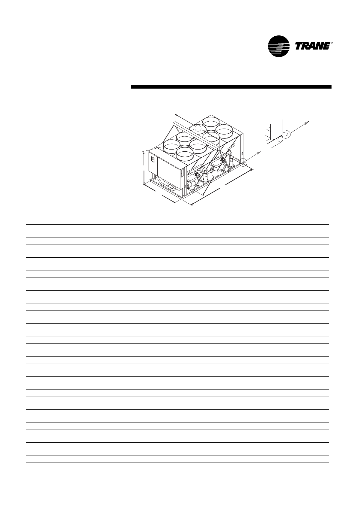
Figure 3 - Rigging the Unit
Table 25
Note: Size 085 does not exist for Total Heat Recovery option but HE version is available
(1) Maximum weight with all options
Unit Size Lengths (mm) Maximum weight (kg)(1)
A B L H max W Aluminium Copper
Standard
RTAD 085 4000 2400 3507 2215 2260 2740 3070
RTAD 100-115-125 4000 2400 4426 2215 2260 3565 4005
RTAD 145-150 4000 2400 5351 2215 2260 4530 4940
RTAD 165-180 4000 2400 6370 2215 2260 5345 5855
RTAD 085-100 HE 4000 2400 4426 2215 2260 3345 3785
RTAD 115-125 HE 4000 2400 5351 2215 2260 4010 4560
RTAD 145-150 HE 4000 2400 6370 2215 2260 5265 5775
Partial Heat Recovery
RTAD 085 4000 2400 3507 2215 2260 2810 3140
RTAD 100-115-125 4000 2400 4426 2215 2260 3635 4075
RTAD 145-150 4000 2400 5351 2215 2260 4605 5015
RTAD 165-180 4000 2400 6370 2215 2260 5430 5940
RTAD 085-100 HE 4000 2400 4426 2215 2260 3405 3845
RTAD 115-125 HE 4000 2400 5351 2215 2260 4080 4630
RTAD 145-150 HE 4000 2400 6370 2215 2260 5340 5850
Total Heat Recovery
RTAD 100 4000 2400 4426 2215 2260 3260 3540
RTAD 115-125 4000 2400 4426 2215 2260 3820 4260
RTAD 145-150 4000 2400 5351 2215 2260 4855 5265
RTAD 165-180 4000 2400 6370 2215 2260 5680 6190
RTAD 085-100 HE 4000 2400 4426 2215 2260 3580 3845
RTAD 115-125 HE 4000 2400 5351 2215 2260 4320 4870
RTAD 145-150 HE 4000 2400 6370 2215 2260 5580 6090
Free Cooling
RTAD 085 4600 2600 3900 2605 2420 3485 RTAD 100-115-125 4600 2600 4850 2605 2420 4920 RTAD 145-150 4600 2600 5770 2645 2420 5720 RTAD 165-180 4600 2600 6810 2745 2460 6985 RTAD 085-100 HE 4600 2600 4850 2605 2420 4540 RTAD 115-125 HE 4600 2600 5770 2645 2420 5480 RTAD 145-150 HE 4600 2600 6810 2745 2460 6905 RTAD 145-150 SE 4000 2400 5351 2215 2260 5265 5675
RTAD 165-180 SE 4000 2400 6370 2215 2260 6145 6655
RTAD 115-125 HE 4000 2400 5351 2215 2260 4740 5150
RTAD 145-150 HE 4000 2400 6370 2215 2260 6145 6655
B
H
A
L
W
Page 26

26 RTAD-SVX01E-E4
Installation - Mechanical
Location Requirements
Isolation and Sound Emission
The most effective form of isolation
is to locate the unit away from any
sound sensitive area. Structurally
transmitted sound can be reduced
by elastomeric vibration eliminators.
Spring isolators are not
recommended. Consult an acoustical
engineer in critical sound
applications. For maximum isolation
effect, isolate water lines and
electrical conduit. Wall sleeves and
rubber isolated piping hangers can
be used to reduce the sound
transmitted through water piping. To
reduce the sound transmitted
through electrical conduit, use
flexible electrical conduit. State and
local codes on sound emissions
should always be considered. Since
the environment in which a sound
source is located affects sound
pressure, unit placement must be
carefully evaluated. Sound power
levels for Trane air-cooled RTAD
chillers are available on request.
For additional reduction of sound
and vibration, install the optional
neoprene isolators. Construct an
isolated concrete pad for the unit or
provide concrete footings at the unit
mounting points. Mount the unit
directly to the concrete pads or
footings. Level the unit using the
base rail as a reference. Use shims
as necessary to level the unit.
Neoprene Isolator (optional)
Installation
Refer to submittals for diagrams.
1 Secure the isolators to the
mounting surface using the
mounting slots in the isolator base
plate. DO NOT fully tighten the
isolator mounting bolts at this
time.
2 Align the mounting holes in the
base of the unit with the threaded
positioning pins on the top of the
isolators.
3 Lower the unit onto the isolators
and secure the isolator to the unit
with a nut. Maximum isolator
deflection should be 1/4 inch
(6 mm).
4 Level the unit carefully. Fully
tighten the isolator mounting
bolts.
Noise Considerations
Locate the outdoor unit away from
sound sensitive areas. If required,
install rubber vibration isolators in
all water piping and use flexible
electrical conduit. Consult an
acoustical engineer for critical
applications. Also refer to Trane
Engineering Bulletins for application
information on RTAD chillers.
Important note for Free-cooling
units:
To reduce sound levels, a sound
enclosure can be mounted around
the compressors. For further sound
level reduction, the fan speed
should be forced onto low speed
(e.g. 740 rpm). This can be done
using the control panel. Make sure
that option 20, shown on the wiring
diagram, is correctly wired.
Storage
Extended storage of the outdoor unit
prior to installation requires the
following precautionary measures:
• Store the outdoor unit in a secure
area.
• At least every three months
(quarterly), check the pressure in
the refrigerant circuits to verify that
the refrigerant charge is intact. If it
is not, contact a qualified service
organization and the appropriate
Trane sales office.
• Close the discharge and liquid line
isolation valves.
CAUTION! Refer to nameplate for
unit weight and additional
installation instructions contained
inside the control panel. Other lifting
arrangements may cause equipment
damage or serious personal injury.
Page 27

RTAD-SVX01E-E4 27
Installation - Mechanical
Foundation
Provide rigid, non-warping mounting
pads or a concrete foundation of
sufficient strength and mass to
support the outdoor unit operating
weight (i.e., including completed
piping, and full operating charges of
refrigerant, oil and water). Refer to
Tables 1-23 for unit operating
weights. Once in place, the outdoor
unit must be level within 1/4" (6 mm)
over its length and width. A base or
foundation is not required if the
selected unit location is level and
strong enough to support the unit's
operating weight. Trane is not
responsible for equipment problems
resulting from an improperly
designed or constructed foundation.
Note: To allow for cleaning under the
condensing coil, it is recommended
that an opening be left between the
unit base and the concrete pad.
Clearances
Refer to Figure 2 for minimum
clearances. Provide enough space
around the outdoor unit to allow the
installation and maintenance
personnel unrestricted access to all
service points. Refer to submittal
drawings for the unit dimensions. A
minimum of four feet is
recommended for compressor
service. Provide sufficient clearance
for the opening of control panel
doors. In all cases, local codes which
require additional clearances will
take precedence over these
recommendations.
Unobstructed flow of condenser air
is essential to maintain chiller
capacity and operating efficiency.
When determining unit placement,
give careful consideration to
assuring a sufficient flow of air
across the condenser heat transfer
surface. Two detrimental conditions
are possible and must be avoided if
optimum performance is to be
achieved: warm air recirculation and
coil starvation. Warm air
recirculation occurs when discharge
air from the condenser fans is
recycled back to the condenser coil
inlet. Coil starvation occurs when
free airflow to (or from) the
condenser is restricted. Both warm
air recirculation and coil starvation
cause reduction in unit efficiency
and capacity due to the increased
head pressures. Debris, trash,
supplies etc. should not be allowed
to accumulate in the vicinity of the
unit. Supply air movement may
draw debris into the condenser coil,
blocking spaces between coil fins
and causing coil starvation. Special
consideration should be given to
low ambient units. Condenser coils
and fan discharge must be kept free
of snow or other obstructions to
permit adequate airflow for
satisfactory unit operation.
Page 28

Unit Water Piping
Thoroughly flush all water piping to
the unit before making the final
piping connections to the unit.
CAUTION! If using an acidic
commercial flushing solution,
construct a temporary bypass
around the unit to prevent damage
to internal components of the
evaporator. To avoid possible
equipment damage, do not use
untreated or improperly treated
system water.
CAUTION! As the unit contains
pressure approved vessels and
sensitive electronic equipment, do
not use arc welding directly on the
unit or even close to the unit. Do
not weld near the Victaulic
connections.
Unit Piping
Components and layout will vary
slightly, depending on the location
of connections and the water source.
Note: The chilled water piping to the
evaporator is to be Victaulic type
connections. For Free Cooling units,
Free Cooling coil connections are
also to be Victaulic
TM
type
connections.
To prevent damage to chilled water
components, do not allow
evaporator pressure (maximum
working pressure) to exceed 16 bar.
Provide shutoff valves in lines to the
gauges to isolate them from the
system when they are not in use.
Use rubber vibration eliminators to
prevent vibration transmission
through the water lines. If desired,
install thermometers in the lines to
monitor entering and leaving water
temperatures. Install a balancing
valve in the leaving water line to
control water flow balance. Install
shutoff valves on both the entering
and leaving water lines so that the
evaporator can be isolated for
service.
CAUTION! A pipe strainer must be
installed in the entering water line.
Failure to do so can allow
waterborne debris to enter the
evaporator.
"Piping components" include all
devices and controls used to provide
proper water system operation and
unit operating safety. These
components and their general
locations are given below.
In situations where equipment must
be installed with less clearance than
recommended, such as frequently
occurs in retrofit and rooftop
applications, restricted airflow is
common. The Main Processor will
direct the unit to make as much
chilled water as possible given the
actual installed conditions. Consult
your Trane sales engineer for more
details.
Note: If the outdoor unit
configuration requires a variance to
the clearance dimensions, contact
your Trane Sales Office
Representative. Also refer to Trane
Engineering Bulletins for application
information on RTAD chillers.
Drainage
Provide a large capacity drain for
water vessel drain-down during
shutdown or repair. The evaporator
is provided with a drain connection.
All local and national codes apply.
The vent on the top of the
evaporator shell is provided to
prevent a vacuum by allowing air
into the evaporator for complete
drainage.
28 RTAD-SVX01E-E4
Installation - Mechanical
Page 29

RTAD-SVX01E-E4 29
Installation - Mechanical
Leaving Chilled Water
Piping
❏ Air vents (to bleed air from
system).
❏Water pressure gauges with
shutoff valves.
❏Vibration eliminators.
❏ Shutoff (isolation) valves.
❏Thermometers.
❏ Clean-out tees.
❏ Balancing valve.
❏ Flow Switch
CAUTION! To prevent evaporator
damage, do not exceed 16 bar
evaporator water pressure.
Heat Recovery Water Piping
Entering:
❏ Air vents
❏Water pressure gauges
❏Vibration eliminator / expansion
compensator
❏ Shutoff valve
❏Thermometers
❏ Pipe strainer
❏ Clean-out tees
Leaving:
❏ Air vents
❏Water pressure gauges
❏Vibration eliminator / expansion
compensator
❏ Shutoff valve
❏Thermometers
❏ Balancing valve
❏ Clean-out tees
Evaporator Drain
A 3/4" drain connection is located
under the evaporator shell. This may
be connected to a suitable drain to
permit evaporator drainage during
unit servicing. A shutoff valve must
be installed on the drain line.
Evaporator Flow Switch
Specific connection and schematic
wiring diagrams are shipped with
the unit. Some piping and control
schemes, particularly those using a
single water pump for both chilled
and hot water must be analyzed to
determine how and or if a flowsensing device will provide desired
operation.
Follow the manufacturer's
recommendations for selection and
installation procedures. General
guidelines for flow switch
installation are outlined below
1. Mount the switch upright, with a
minimum of 5 pipe diameters of
straight horizontal run on each
side. Do not install close to
elbows, orifices or valves.
Note: The arrow on the switch must
point in the direction of flow.
2. To prevent switch fluttering,
remove all air from the water
system.
Note: The UCM-CLD provides a
6-second time delay after a "loss-offlow" diagnostic before shutting the
unit down. Contact a qualified
service representative if nuisance
machine shutdowns persist.
3. Adjust the switch to open when
water flow falls below nominal.
Evaporator data is given in
Tables 1-22. Flow switch contacts are
closed on proof of water flow.
4. Install a pipe strainer in the
entering evaporator water line to
protect components from
waterborne debris.
Entering Chilled Water
Piping
❏ Air vents (to bleed air from
system).
❏Water pressure gauges with
shutoff valves.
❏Vibration eliminators.
❏ Shutoff (isolation) valves.
Thermometers (if desired).
❏ Clean-out tees.
❏ Pipe strainer.
CAUTION! Install strainer in
evaporator water inlet piping. Failure
to do so can result in evaporator
tube damage.
Page 30

Water Treatment
CAUTION! If calcium chloride is used
for water treatment, an applicable
corrosion inhibitor must also be
used. Failure to do so may result in
damage to system components.
Dirt, scale, products of corrosion and
other foreign material will adversely
affect heat transfer between the
water and system components.
Foreign matter in the chilled water
system can also increase pressure
drop and, consequently, reduce
water flow.
Proper water treatment must be
determined locally, depending on
the type of system and local water
characteristics. Neither salt nor
brackish water is recommended for
use in Trane air-cooled Series R™
chillers. Use of either will lead to a
shortened life to an indeterminable
degree. Trane encourages the
employment of a reputable water
treatment specialist, familiar with
local water conditions, to assist in
this determination and in the
establishment of a proper water
treatment program.
Using untreated or improperly
treated water in these units may
result in inefficient operation and
possible tube damage. Consult a
qualified water treatment specialist
to determine whether treatment is
needed. The following disclamatory
label is provided on each RTAD unit:
Note: The use of improperly treated
or untreated water in this equipment
may result in scaling, erosion,
corrosion, algae or slime. The
services of a qualified water
treatment specialist should be
engaged to determine what
treatment, if any, is advisable. Trane
warranty specifically excludes
liability for corrosion, erosion or
deterioration of Trane equipment.
CAUTION! Do not use untreated or
improperly treated water. Equipment
damage may occur.
30 RTAD-SVX01E-E4
Installation - Mechanical
Figure 4 - Evaporator Water Pressure Drop RTAD
1 = 085 STD
2 = 115 STD, 100 HE
3 = 100 STD, 085 HE
4 = 125 STD, 145 STD, 150 STD, 115 HE, 125 HE
5 = 165 STD, 180 STD, 145 HE, 150 HE
Note: Valid for standard, Free-cooling and Heat Recovery versions
kPa
l/s
Page 31

Installation - Mechanical
RTAD-SVX01E-E4 31
Figure 5 - RTAD 115HE - 125HE - 145SE - 150SE
Single pump available static pressure
1 = LRN 208-13/5.5
2 = LRN 208-14/7.5
3 = SIL 208-16/11
4 = SIL 208-17/15
Figure 6 - RTAD 115HE - 125HE - 145SE - 150SE
Dual pump available static pressure
1 = JRN 208-13/5.5
2 = JRN 208-14/7.5
3 = DIL 208-16/11
4 = DIL 208-17/15
1
2
3
4
kPa
l/s
1
2
3
4
kPa
l/s
Page 32

32 RTAD-SVX01E-E4
Installation - Mechanical
Figure 7 - RTAD 145HE - 150HE - 165SE - 180SE
Single Pump Available Static Pressure
1 = LRN 208-13/5.5
2 = LRN 208-14/7.5
3 = SIL 208-16/11
4 = SIL 208-17/15
Figure 8 - RTAD 145HE - 150HE - 165SE - 180SE
Dual pump Available static pressure
1 = JRN 208-13/5.5
2 = JRN 208-14/7.5
3 = DIL 208-16/11
4 = DIL 208-17/15
1
2
3
4
kPa
l/s
kPa
l/s
Page 33

RTAD-SVX01E-E4 33
Installation - Mechanical
Figure 9 - RTAD 115HE - 125HE - 145SE - 150SE
Pump Capacity Curve Single Pump
1 = LRN 208-13/5.5
2 = LRN 208-14/7.5
3 = SIL 208-16/11
4 = SIL 208-17/15
Figure 10 - RTAD 115HE - 125HE - 145SE - 150SE
Pump Capacity Curve Dual Pump
1 = LRN 208-13/5.5
2 = LRN 208-14/7.5
3 = SIL 208-16/11
4 = SIL 208-17/15
kW
l/s
kW
l/s
Page 34

34 RTAD-SVX01E-E4
Installation - Mechanical
Figure 11 - RTAD 145HE - 150HE - 165SE - 180SE
Pump Current Curve Single Pump
1 = JRN 208-13/5.5
2 = JRN 208-14/7.5
3 = DIL 208-16/11
4 = DIL 208-17/15
Figure 12 - RTAD 145HE - 150HE - 165SE - 180SE
Pump Current Curve Dual Pump
1 = JRN 208-13/5.5
2 = JRN 208-14/7.5
3 = DIL 208-16/11
4 = DIL 208-17/15
A
l/s
A
l/s
25
4
20
3
15
A
10
5
0
0 5 10 15 20 25 30 35 40 45
2
1
A
4
3
2
1
Page 35

RTAD-SVX01E-E4 35
Installation - Mechanical
Figure 13 - Water Pressure Drop RTAD Free Cooling - Compressor Mode
Figure 14 - Water Pressure Drop RTAD Free Cooling - Free Cooling Mode
1 = 085 STD
2 = 085 HE, 100 STD
3 = 100 HE, 115 STD
4 = 115 HE, 125 HE, 145 STD, 150 STD
5 = 125 STD
6 = 145 HE, 150 HE, 165 STD, 180 STD
kPa
l/s
kPa
l/s
Page 36

36 RTAD-SVX01E-E4
Installation - Mechanical
Figure 15 - Condenser Water Pressure Drop RTAD Partial Heat Recovery - Heating Mode
1 = 085-100
2 = 115-125
3 = 145-150
4 = 165-180
Figure 16 - Condenser Water Pressure Drop RTAD Total Heat Recovery - Heating Mode
1 = 085-100
2 = 115-125
3 = 145-150
4 = 165-180
l/s
kPa
l/s
kPa
Page 37

Figure 17 - 3-way Valve Pressure Drop RTAD Total Heat Recovery - Heating mode
1 = 085-100-115-125
2 = 145-150-165-180
Figure 18 - Suggested piping for typical RTAD Standard and Heat Recovery evaporator
without hydraulic module
1. Gate valve
2. Water strainer
3. Thermometer (user option)
4. Vibration eliminator
5. Relief valve
6. Valved pressure gauge
7. Ve n t
8. Drain
9. Flow switch (chilled water flow)
10.Balancing valve
7
8
9
10
6
5
4
3
2
1
1
3
4
kPa
l/s
RTAD-SVX01E-E4 37
Installation - Mechanical
Page 38

38 RTAD-SVX01E-E4
Installation - Mechanical
Figure 19 - Suggested piping for typical RTAD with hydraulic module
Figure 20 - Suggested piping for typical RTAD Free Cooling evaporator
1. Gate valve
2. Water strainer
3. Thermometer (user option)
4. Vibration eliminator
5. Relief valve
6. Valved pressure gauge
7. V e n t
8. Drain
9. Flow switch (chilled water flow)
10.Balancing valve
1. Gate valve
2. Water strainer
3. Thermometer (user option)
4. Vibration eliminator
5. Relief valve
6. Pressure gauge
7. Ve n t
8. Drain
9. Flow switch (chilled water flow) Trane-
supplied
10.Balancing valve
11. Pressure port
12. Expansion vessel (option)
7
7
1
12
5
8
9
3
10
11
4
6
2
8
3
1
1
Page 39

RTAD-SVX01E-E4 39
Installation - Mechanical
Figure 21 - Suggested condenser piping for typical RTAD PHR
Figure 22 - Suggested condenser piping for typical RTAD THR with 3-way valve
A. Trane-supplied with 3-way valve
option
1. Gate valve
2. Water strainer
3. Thermometer (user option)
4. Vibration eliminator
5. Relief valve
6. Valved pressure gauge
7. Ve n t
8. Drain
9. Flow switch (warm water flow)
10.Balancing valve
11. Clean out tee
A. Trane-supplied
1. Gate valve
2. Water strainer
3. Thermometer (user option)
4. Vibration eliminator
5. Relief valve
6. Valved pressure gauge
7. Ve n t
8. Drain
9. Flow switch (warm water flow)
10.Balancing valve
11. Clean out tee
Page 40

40 RTAD-SVX01E-E4
Installation - Mechanical
Figure 23 - Suggested condenser piping for typical RTAD THR without 3-way valve
A. Trane-supplied without 3-way valve
option
1. Gate valve
2. Water strainer
3. Thermometer (user option)
4. Vibration eliminator
5. Relief valve
6. Valved pressure gauge
7. Ve n t
8. Drain
9. Flow switch (warm water flow)
10.Balancing valve
11. Clean out tee
Page 41

RTAD-SVX01E-E4 41
Installation - Mechanical
Freeze Protection
If the unit will remain operational at
subfreezing ambient temperatures,
the chilled water system must be
protected from freezing, following
the steps listed below
1 Heaters are factory-installed on the
packaged unit evaporator and will
protect it from freezing in ambient
temperatures down to -18°C (0°F).
2 Install heat tape on all water
piping, pumps, and other
components that may be damaged
if exposed to freezing
temperatures. Heat tape must be
designed for low ambient
temperature applications. Heat
tape selection should be based on
the lowest expected ambient
temperature.
3 Add a non-freezing, low
temperature, corrosion inhibiting,
heat transfer fluid to the chilled
water system. The solution must
be strong enough to provide
protection against ice formation at
the lowest anticipated ambient
temperature. Refer to Tables 1-22
for evaporator water storage
capacities.
Note: Use of glycol type antifreeze
reduces the cooling capacity of the
unit and must be considered in the
design of the system specifications.
Note: All Free Cooling units must be
freeze protected with 30% Ethylene
Glycol in the cooling loop circuit
which is the most convenient
percentage in order to protect the
unit against freezing.
Protection coverage with 30%
Ethylene Glycol:
- freezing point without burst effect
=-13°C;
- freezing point with burst effect
= - 50°C.
In ambient temperatures below
-18°C, the water circuit must be
protected against freezing by the
one of the following methods:
- purge the water circuit or add an
an anti-freeze fluid.
- Activate the heat tapes on the unit
and do not shut the unit down.
Freeze protection with hydraulic
module and dual pump
To protect the chiller against freezing,
there are 5 means of protection:
• Using the proper glycol percentage
in the water (no risk of damage due
to power failure)
• Draining the unit during the cold
season. However, be aware of the
corrosion process when drained.
• Using the heat tape protection
(protect the unit down to -18°C)
• Using freeze protection by pump
activation.
• Using pump activation and heat
protection one being a safety for the
other.
CAUTION!
When using the freeze protection by
pump activation during the cold
season, water must be able to
circulate freely. Check that no closure
valve or other device might block
waterflow.
Note:
For dual pump hydraulic model,
activation of the heat tape is not done
through the thermostat but by the
pump controller.
Single pump hydraulic module does
not provide protection by pump
activation and require the thermostat.
Water Pressure Gauges
Install field-supplied pressure
components as shown in
Figure 18-23. Locate pressure
gauges or taps in a straight run of
pipe; avoid placement near elbows,
etc. Be sure to install the gauges at
the same elevation on each shell if
the shells have opposite-end water
connections.
To read manifolded pressure
gauges, open one valve and close
the other (depending upon the
reading desired). This eliminates
errors resulting from differently
calibrated gauges installed at
unmatched elevations.
Water Pressure Relief
Valves
CAUTION! To prevent shell damage,
install pressure relief valves in the
evaporator water system.
Install a water pressure relief valve
in the evaporator inlet piping
between the evaporator and the inlet
shutoff valve, as shown in
Figures 18-23. Water vessels with
close-coupled shutoff valves have a
high potential for hydrostatic
pressure buildup on a water
temperature increase. Refer to
applicable codes for relief valve
installation guidelines.
Page 42

42 RTAD-SVX01E-E4
Installation - Electrical
% = % ethylene glycol
°C = Brine temperature
1 = Liquid
2 = Freezing without burst effect
3 = Freezing with burst effect
Leaving water temperature (°C)
Glycol (%)
Using glycol with hydraulic module
If the glycol brine percentage is not at
the recommended percentage
(greyed area), corrosion inhibitor
present in the glycol may not be
efficient enough.
For instance, not only a glycol
protection of 15% will only provide
protection to the unit against freezing
down to -5°C but also it might
generate additional corrosion that
could damage the pumps mechanical
seals.
CAUTION!
Some corrosion inhibitors may be
harmful to the mechanical seal or to
the cast iron of the pump.
In case of application with negative
temperature at the evaporator or
usage of another type of fluid, please
contact your local Trane sales
engineer. A relief valve is located at
pump suction limiting water circuit
pressure at 4 bar. Nitrogen pressure
inside of the expansion tank must be
equal to the geometric height of the
installation + 0.5 bar. In order to avoid
air entering in the water circuit,
expansion tank must be inflated with
nitrogen. Pressure must be checked
yearly. For a good pump operation,
pump suction pressure must be
between 0.5 and 3.5 bar when pump
runs.
Heat Recovery Units
The heat recovery condenser(s) is
(are) insulated and a heater is
factory-installed and will protect
from freezing in ambient
temperatures down to -18°C.
Note: The inlet and outlet tubes and
the optional 3-way valve (Total Heat
Recovery units) should be protected
against freezing by one of the
following methods:
-
install heat tape on all water piping
and around the 3-way valve
- add ethylene glycol or equivalent
anti-freeze fluid.
°C
%
Page 43

Installation - Electrical
General Recommendations
WARNING! The warning label shown
in Figure 24 is displayed on the
equipment. Strict adherence to
these warnings must be observed.
Failure to do so may result in
personal injury or death.
All wiring must comply with CE codes.
Typical field wiring diagrams are
included in the unit control panel.
Minimum circuit ampacities and other
unit electrical data are on the unit
nameplate and in the general data
tables. See the unit order specifications
for actual electrical data. Specific
electrical schematics and connection
diagrams are shipped with the unit.
Figure 24 - Warning Label
CAUTION! To avoid corrosion and
overheating at terminal connections,
use copper conductors only. Failure
to do so may result in damage to
the equipment.
Do not allow conduit to interfere
with other components, structural
members or equipment. Control
voltage (115V) wiring in conduit
must be separate from conduit
carrying low voltage (<30V) wiring.
CAUTION! To prevent control
malfunctions, do not run low
voltage wiring (<30V) in conduit
with conductors carrying more than
30 volts.
RTAD-SVX01E-E4 43
Page 44

44 RTAD-SVX01E-E4
Installation - Electrical
Table 26 - Unit Wiring 400/3/50 - Standard cooling unit / Partial Heat Recovery and Total Heat Recovery units
Unit Size
Standard
085 1 242 255 0.90 250 6 x 125 0.217
100 1 282 306 0.88 400 6 x 160 0.217
115 1 323 359 0.89 400 6 x 200 0.217
125 1 387 425 0.90 500 6 x 250 0.217
145 1 437 471 0.90 500 6 x 250 0.217
150 1 477 502 0.89 630 6 x 250 0.217
165 1 527 570 0.89 630 315 + 250 0.217
180 1 576 608 0.89 630 6 x 315 0.217
High Efficiency
085 1 242 255 0.90 250 6 x 125 0.217
100 1 291 315 0.88 400 6 x 160 0.217
115 1 332 368 0.89 400 6 x 200 0.217
125 1 405 443 0.90 500 6 x 250 0.217
145 1 446 480 0.90 500 6 x 250 0.217
150 1 486 511 0.89 630 6 x 250 0.217
High Ambient
085 1 242 255 0.90 400 6 x 160 0.217
100 1 291 315 0.88 400 6 x 200 0.217
115 1 332 368 0.89 400 6 x 250 0.217
125 1 405 443 0.90 500 6 x 250 0.217
145 1 446 480 0.90 630 6 x 250 0.217
150 1 486 511 0.89 630 6 x 315 0.217
165 1 527 570 0.89 630 400 + 315 0.217
180 1 576 608 0.89 800 6 x 400 0.217
Standard Low Noise
085 1 230 243 0.90 250 6 x 125 0.217
100 1 270 294 0.88 400 6 x 160 0.217
115 1 311 347 0.89 400 6 x 200 0.217
125 1 375 413 0.90 500 6 x 250 0.217
145 1 419 453 0.90 500 6 x 250 0.217
150 1 457 482 0.89 630 6 x 250 0.217
165 1 505 548 0.89 630 315 + 250 0.217
180 1 552 584 0.89 630 6 x 315 0.217
High Efficiency Low Noise
085 1 230 243 0.90 250 6 x 125 0.217
100 1 275 299 0.88 400 6 x 160 0.217
115 1 316 352 0.89 400 6 x 200 0.217
125 1 385 423 0.90 500 6 x 250 0.217
145 1 424 458 0.90 500 6 x 250 0.217
150 1 462 487 0.89 630 6 x 250 0.217
Standard Low Noise with Night Noise Set Back option
085 1 226 238 0.90 250 6 x 125 0.217
100 1 270 295 0.88 400 6 x 160 0.217
115 1 312 348 0.89 400 6 x 200 0.217
125 1 376 414 0.90 500 6 x 250 0.217
145 1 417 451 0.90 500 6 x 250 0.217
150 1 453 478 0.89 630 6 x 250 0.217
165 1 503 546 0.89 630 315 + 250 0.217
180 1 548 580 0.89 630 6 x 315 0.217
High Efficiency Low Noise with Night Noise Set Back option
085 1 231 244 0.90 250 6 x 125 0.217
100 1 270 295 0.88 400 6 x 160 0.217
115 1 317 353 0.89 400 6 x 200 0.217
125 1 381 419 0.90 500 6 x 250 0.217
145 1 381 456 0.90 500 6 x 250 0.217
150 1 381 483 0.89 630 6 x 250 0.217
Nbr of Power
Connections
Maximum
Amps (1)
Starting
Amps (2)
Power
Factor (5)
Disconnect
Switch Size (A)
Compressor
Fuse Size (A)
Evaporator
heater (kW)
Page 45

Installation - Electrical
Table 27 - Unit Wiring 400/3/50/ cont - Standard cooling unit / Partial Heat Recovery and Total Heat Recovery units
Unit Size
Standard with High External Static Pressure
085 1 231 244 0.90 250 6 x 125 0.217
100 1 278 302 0.88 400 6 x 160 0.217
115 1 319 355 0.89 400 6 x 200 0.217
125 1 383 421 0.90 500 6 x 250 0.217
145 1 427 461 0.90 500 6 x 250 0.217
150 1 463 488 0.89 630 6 x 250 0.217
165 1 516 559 0.89 630 315 + 250 0.217
180 1 561 593 0.89 630 6 x 315 0.217
High Efficiency with High External Static Pressure
085 1 239 251 0.90 250 6 x 125 0.217
100 1 278 302 0.88 400 6 x 160 0.217
115 1 327 363 0.89 400 6 x 200 0.217
125 1 391 429 0.90 500 6 x 250 0.217
145 1 435 469 0.90 500 6 x 250 0.217
150 1 471 496 0.89 630 6 x 250 0.217
Table 28 - Motor Data 400/3/50 - Standard cooling unit / Partial Heat Recovery and Total Heat Recovery units
(400V)
Unit Size Qty Ckt 1 Ckt 2 Ckt 1 Ckt 2 Ckt 1 Ckt 2 Qty kW FLA size (A) VA A
Standard
085 2 80 80 106 106 144 144 6 2.05 4.5 3 x 50 1600 4
100 2 95 95 125 125 180 180 6 2.05 4.5 3 x 50 1600 4
115 2 111 111 14 6 146 2 1 7 217 6 2 . 0 5 4.5 3 x 5 0 1 6 0 0 4
125 2 135 135 178 178 259 259 6 2.05 4.5 3 x 50 1600 4
145 2 162 135 214 178 291 259 9 2.05 4.5 3 x 63 1600 4
150 2 162 162 214 214 291 291 10 2.05 4.5 3 x 63 1600 4
165 2 196 162 259 214 354 291 11 2.05 4.5 3 x 63 1600 4
180 2 196 196 259 259 354 354 12 2.05 4.5 3 x 63 1600 4
High Efficiency
085 2 80 80 106 106 144 144 6 2.05 4.5 3 x 50 1600 4
100 2 95 95 125 125 180 180 8 2.05 4.5 3 x 50 1600 4
115 2 111 111 14 6 146 2 1 7 217 8 2 . 0 5 4.5 3 x 5 0 1 6 0 0 4
125 2 135 135 178 178 259 259 10 2.05 4.5 3 x 50 1600 4
145 2 162 135 214 178 291 259 11 2.05 4.5 3 x 63 1600 4
150 2 162 162 214 214 291 291 12 2.05 4.5 3 x 63 1600 4
Standard Low Noise
085 2 80 80 106 106 144 144 6 1.30 2.5 3 x 50 1600 4
100 2 95 95 125 125 180 180 6 1.30 2.5 3 x 50 1600 4
115 2 111 111 14 6 146 2 1 7 217 6 1. 3 0 2 . 5 3 x 5 0 1 6 0 0 4
125 2 135 135 178 178 259 259 6 1.30 2.5 3 x 50 1600 4
145 2 162 135 214 178 291 259 9 1.30 2.5 3 x 63 1600 4
150 2 162 162 214 214 291 291 10 1.30 2.5 3 x 63 1600 4
165 2 196 162 259 214 354 291 11 1.30 2.5 3 x 63 1600 4
180 2 196 196 259 259 354 354 12 1.30 2.5 3 x 63 1600 4
High Efficiency Low Noise option
085 2 80 80 106 106 144 144 6 1.30 2.5 3 x 50 1600 4
100 2 95 95 125 125 180 180 8 1.30 2.5 3 x 50 1600 4
115 2 111 111 14 6 146 2 1 7 217 8 1. 3 0 2 . 5 3 x 5 0 1 6 0 0 4
125 2 135 135 178 178 259 259 10 1.30 2.5 3 x 50 1600 4
145 2 162 135 214 178 291 259 11 1.30 2.5 3 x 63 1600 4
150 2 162 162 214 214 291 291 12 1.30 2.5 3 x 63 1600 4
Standard Low Noise with Night Noise Set Back option
085 2 80 80 106 106 144 144 4 1.05 2.6 3 x 50 1600 4
100 2 95 95 125 125 180 180 6 1.05 2.6 3 x 50 1600 4
115 2 111 111 14 6 146 2 1 7 217 6 1. 0 5 2 . 6 3 x 5 0 1 6 0 0 4
125 2 135 135 178 178 259 259 6 1.05 2.6 3 x 50 1600 4
145 2 162 135 214 178 291 259 8 1.05 2.6 3 x 63 1600 4
150 2 162 162 214 214 291 291 8 1.05 2.6 3 x 63 1600 4
165 2 196 162 259 214 354 291 10 1.05 2.6 3 x 63 1600 4
180 2 196 196 259 259 354 354 10 1.05 2.6 3 x 63 1600 4
Nbr of Power
Connections
Maximum
Amps (1)
Starting
Amps (2)
Power
Factor (5)
Disconnect
Switch Size (A)
Compressor
Fuse Size (A)
Evaporator
heater (kW)
RLA Amps Max Amps (3) Starting Amps (4) Fans fuse
Compressor (Each) Fans (Each) Control
RTAD-SVX01E-E4 45
Page 46

46 RTAD-SVX01E-E4
Installation - Electrical
Table 29 - Motor Data 400/3/50/ cont - Standard cooling unit / Partial Heat Recovery and Total Heat Recovery units
Unit Size Qty Ckt 1 Ckt 2 Ckt 1 Ckt 2 Ckt 1 Ckt 2 Qty kW FLA size (A) VA (400V)
High Efficiency Low Noise with Night Noise Set Back option
085 2 80 80 106 106 144 144 6 1.05 2.6 3 x 50 1600 4
100 2 95 95 125 125 180 180 6 1.05 2.6 3 x 50 1600 4
115 2 111 111 14 6 146 2 1 7 217 8 1. 0 5 2 . 6 3 x 5 0 1 6 0 0 4
125 2 135 135 178 178 259 259 8 1.05 2.6 3 x 50 1600 4
145 2 162 135 214 178 291 259 10 1.05 2.6 3 x 63 1600 4
150 2 162 162 214 214 291 291 10 1.05 2.6 3 x 63 1600 4
Standard with High External Static Pressure
085 2 80 80 106 106 144 144 4 2.21 3.9 3 x 50 1600 4
100 2 95 95 125 125 180 180 6 2.21 3.9 3 x 50 1600 4
115 2 111 111 14 6 146 2 1 7 217 6 2 . 2 1 3.9 3 x 5 0 1 6 0 0 4
125 2 135 135 178 178 259 259 6 2.21 3.9 3 x 50 1600 4
145 2 162 135 214 178 291 259 8 2.21 3.9 3 x 63 1600 4
150 2 162 162 214 214 291 291 8 2.21 3.9 3 x 63 1600 4
165 2 196 162 259 214 354 291 10 2.21 3.9 3 x 63 1600 4
180 2 196 196 259 259 354 354 10 2.21 3.9 3 x 63 1600 4
High Efficiency with High External Static Pressure
085 2 80 80 106 106 144 144 6 2.21 3.9 3 x 50 1600 4
100 2 95 95 125 125 180 180 6 2.21 3.9 3 x 50 1600 4
115 2 111 111 14 6 146 2 1 7 217 8 2 . 2 1 3.9 3 x 5 0 1 6 0 0 4
125 2 135 135 178 178 259 259 8 2.21 3.9 3 x 50 1600 4
145 2 162 135 214 178 291 259 10 2.21 3.9 3 x 63 1600 4
150 2 162 162 214 214 291 291 10 2.21 3.9 3 x 63 1600 4
Notes:
1. Maximum Compressors FLA + all fans FLA + control Amps
2. Starting Amps of the circuit with the largest compressor circuit including fans plus RLA of the second circuit including fans + control Amps
3. Maximum FLA per compressor.
4. Compressors starting Amps, Star delta start.
5. Compressor Power Factor
Table 30 - Compressor motor electrical data - 50 Hz - Free Cooling unit
Unit Size Nominal voltage Maximum unit kW Maximum RLA (1) Starting amps Power factor
(V/Ph/Hz) (kW) (A) (A)
RTAD 085 FC STD 400/3/50 149 239 251 0.90
RTAD 085 FC STD 400/3/50 149 239 251 0.90
RTAD 100 FC STD 400/3/50 169 278 302 0.88
RTAD 115 FC STD 400/3/50 199 319 355 0.89
RTAD 125 FC STD 400/3/50 244 391 429 0.90
RTAD 145 FC STD 400/3/50 268 431 465 0.90
RTAD 150 FC STD 400/3/50 291 471 496 0.89
RTAD 165 FC STD 400/3/50 294 520 563 0.89
RTAD 180 FC STD 400/3/50 352 569 601 0.89
RTAD 085 FC HE 400/3/50 149 239 251 0.90
RTAD 100 FC HE 400/3/50 174 286 310 0.88
RTAD 115 FC HE 400/3/50 204 327 363 0.89
RTAD 125 FC HE 400/3/50 249 399 437 0.90
RTAD 145 FC HE 400/3/50 273 439 473 0.90
RTAD 150 FC HE 400/3/50 296 479 504 0.89
(1) To take in account for the sizing of power cables
RLA Amps Max Amps (3) Starting Amps (4) Fans fuse
Compressor (Each) Fans (Each) Control
Page 47

Installation - Electrical
RTAD-SVX01E-E4 47
Table 31 - General electrical data
Unit Size Nominal voltage Control circuit
(V/Ph/Hz) (VA)
RTAD 085 FC STD 400/3/50 150 1600 35
RTAD 100 FC STD 400/3/50 150 1600 35
RTAD 115 FC STD 400/3/50 150 1600 35
RTAD 125 FC STD 400/3/50 150 1600 35
RTAD 145 FC STD 400/3/50 150 1600 35
RTAD 150 FC STD 400/3/50 150 1600 35
RTAD 165 FC STD 400/3/50 150 1600 35
RTAD 180 FC STD 400/3/50 150 1600 35
RTAD 085 FC HE 400/3/50 150 1600 35
RTAD 100 FC HE 400/3/50 150 1600 35
RTAD 115 FC HE 400/3/50 150 1600 35
RTAD 125 FC HE 400/3/50 150 1600 35
RTAD 145 FC HE 400/3/50 150 1600 35
RTAD 150 FC HE 400/3/50 150 1600 35
Table 32 - Electrical connections
Unit Size
RTAD 085 FC STD 6 x 125 250 95 150
RTAD 100 FC STD 6 x 160 400 185 240
RTAD 115 FC STD 6 x 200 400 185 240
RTAD 125 FC STD 6 x 250 500 240 240
RTAD 145 FC STD 6 x 250 500 240 240
RTAD 150 FC STD 6 x 250 630 2 x 150 2 x 300
RTAD 165 FC STD 315 + 250 630 2 x 150 2 x 300
RTAD 180 FC STD 6 x 315 630 2 x 150 2 x 300
RTAD 085 FC HE 6 x 125 250 95 150
RTAD 100 FC HE 6 x 160 400 185 240
RTAD 115 FC HE 6 x 200 400 185 240
RTAD 125 FC HE 6 x 250 500 240 240
RTAD 145 FC HE 6 x 250 500 240 240
RTAD 150 FC HE 6 x 250 630 2 x 150 2 x 300
(1) To take in account for the sizing of power cables
Table 33 - Hydraulic module electrical data
Single or dual pump
Pump 1 Pump 2 Pump 3 Pump 4
Standard Efficiency unit
145 kW (1) 5.0 6.5 9.2 12.1
150 kW (1) 5.1 6.8 9.7 12.7
165 kW (1) 5.1 7.1 10.1 13.2
180 kW (1) 5.2 7.3 10.5 13.6
High Efficiency unit
115 kW (1) 4.7 5.9 8.3 11.0
125 kW (1) 4.9 6.4 9.1 12.0
145 kW (1) 5.0 6.6 9.3 12.2
150 kW (1) 5.1 6.8 9.7 12.6
All sizes
Maximum amps (A) 10.3 13.8 20 26.5
Power factor 0.89 0.89 0.88 0.88
(1) Power input at Eurovent conditions: Ambient temperature 35°C, water temperature 12/7°C
Crankcase heater
Compressor
(W)
Short circuit intensity
(kA)
Compressor
fuse size (1)
(A)
Disconnect
switch size (1)
(A)
Minimum connecting
wire (1)
(mm²)
Maximum connecting
wire (1)
(mm²)
Page 48

48 RTAD-SVX01E-E4
Installation - Electrical
Power Supply Wiring
All power supply wiring must be
sized and selected accordingly by
the project engineer in accordance
with EN 60204.
WARNING! To prevent injury or
death, disconnect all electrical
power sources before completing
wiring connections to the unit.
All wiring must comply with CE
electrical codes. The installing (or
electrical) contractor must provide
and install the system
interconnecting wiring and the
power supply wiring. It must be
properly sized and equipped with
the appropriate fused disconnect
switches. The type and installation
location(s) of the fused disconnects
must comply with all applicable
codes.
CAUTION! Use only copper
conductors for terminal connections
to avoid corrosion or overheating.
Cut holes into the sides of the
control panel for the appropriately
sized power wiring conduits.
The wiring is passed through these
conduits and connected to the
terminal blocks, optional unitmounted disconnects, or circuit
breakers.
To provide proper phasing of
3-phase input, make connections as
shown in field wiring diagrams and
as stated on the Warning label in the
starter panel. For additional
information on proper phasing, refer
to "Unit Voltage Phasing." Proper
equipment ground must be provided
to each ground connection in the
panel (one for each customersupplied conductor per phase).
Control Power Supply
The unit is equipped with a control
power transformer; it is not necessary
to provide additional control power
voltage to the unit. The RTAD units are
factory-connected for 400V/3/50 with a
factory-installed control power
transformer.
Heater Power Supply
The evaporator shell is insulated from
ambient air and protected from
freezing temperatures by electric
heaters. A heater also protects the
heat recovery condenser(s). Whenever
the air temperature drops to
approximately 37°F (2.8°C), the
thermostat energizes the heaters. The
heaters will provide protection from
ambient temperatures down to -18°C
(0°F). The heaters are factory-wired
back to the unit control panel.
As an option, the heater will be
energized by a thermostat when the
temperature drops to approximately
3°C.
CAUTION! Control panel main
processor does not check for loss of
power to the heat tape nor does it
verify thermostat operation. A
qualified technician must verify power
to the heat tape and confirm
operation of the heat tape thermostat
to avoid catastrophic damage to the
evaporator.
Water Pump Power Supply
Provide power supply wiring with
fused disconnect for the chilled
water pump(s).
1. As standard, all units have single
point power connection.
2. LRA (Locked Rotor Amps) - based
on full winding (x-line) start units.
LRA for wye-delta starters is 1/3 of
LRA of x-line units.
3. VOLTAGE UTILIZATION RANGE:
Rated Voltage Utilization Range
400/50/3 340-460
For the RTAD 100 only, the
Utilization Range is 360 - 460 Volts
Installer-Supplied
Components
CAUTION! Customer wiring interface
connections are shown in the
electrical schematics and connection
diagrams that are shipped with the
unit.The installer must provide the
following components if not ordered
with the unit:
❏ Power supply wiring (in conduit)
for all field-wired connections.
❏ All control (interconnecting) wiring
(in conduit) for field supplied
devices.
❏ Fused-disconnect switches or
circuit breakers.
❏ Power factor correction capacitors.
Page 49

RTAD-SVX01E-E4 49
Installation - Electrical
Interconnecting Wiring
Chilled Water Flow (Pump) Interlock
The model RTAD chiller requires a
field-supplied control voltage contact
input through a flow proving switch
6S56 and an auxilary contact 6K51 of
the chilled water pump contactor.
IMPORTANT: Do not turn the chiller
on or off using the chilled-water
interlocks.
When making field connections,
refer to the appropriate field layout,
wiring schematics, and control
diagrams that ship with the unit.
Chilled-water pump control
CAUTION! The chilled-water pump
must operate for a minimum of one
minute after the UCM-CLD receives
a command, through the external
Auto/Stop input, to shut down the
chilled-water system.
On the RTAD units, the controller
will initiate the "Run:Unload" mode
to terminate a cycle from any of the
following:
• Stop key pressed
• Loss of load
• External Auto/Stop input opened
The "Run:Unload" operating mode
commands the compressor to
completely unload, which takes
about ½ minute. This will allow the
compressors to be totally unloaded
for the next start-up. If only the
proof-of-chilled-water-flow interlock
is used, the chiller will shut down
with an immediate (non-friendly)
shutdown and initiate an automatic
reset diagnostic.
1. External Auto/Stop (terminals
A1TB3-3 and -4). This input is
supplied by the field. A contact
closure will start the chiller water
pump and chiller, via the UCMCLD pump control contacts.
Opening the contact will put the
operating compressors into
"Run:Unload" mode and initiate a
timing period (1 to 30 minutes,
adjustable through the Clear
Language Display). This will delay
termination of the chilled-water
pump operation via the UCM
pump control contacts. Examples
of the input terminals 1UTB3-3
and -4 would be a time clock,
ambient thermostat, building
automation system, etc.
2. UCM-CLD Pump Control Contacts
(Terminals A1 TB4-8 and -9)
This output is a set of contacts that
will close, starting the chilled-water
pump when the external Auto/Stop
contacts are closed. When the
contacts are opened, 1 to 30 minutes
later (adjustable through the Clear
Language Display), the UCM-CLD
pump control contacts open.
3. Proof-of-Chilled-Water-Flow
Interlock (Terminals A1 TB3-1
and -2)
This terminal must be field-installed.
Contact closure between the
terminals indicates proof of chilledwater flow. Examples of this are a
pump starter auxiliary contact, flow
switch, differential pressure switch,
or a contact from a building
automation system. Opening of this
contact will immediately shut down
the chiller and initiate an automatic
reset diagnostic, indicating loss of
chilled-water flow.
Page 50

50 RTAD-SVX01E-E4
Installation - Electrical
Specification for Free Cooling units:
1. External Auto/Stop (terminals A70
J8-IDH14 and 6X2-1).
This input is supplied by the field. A
contact closure will start the chiller
water pump and chiller, via the
UCM-CLD and A70 (regulation for
Free Cooling mode) pump control
contacts. Opening the contact will
put the operating compressors into
"Run:Unload" mode and initiate a
timing period (1 to 30 minutes,
adjustable through the Clear
Language Display). This will delay
termination of the chilled-water
pump operation via the UCM pump
control contacts. Examples of the
input terminals 1UTB3-3 and -4
would be a time clock, ambient
thermostat, building automation
system, etc.
2. UCM-CLD and A 70 Pump Control
Contacts (Terminals A70 J14-C7
and -NO7)
This output is a set of contacts
that will close, starting the chilledwater pump when the external
Auto/Stop contacts are closed.
When the contacts are opened,
1 to 30 minutes later (adjustable
through the Clear Language
Display), the UCM-CLD and A70
pump control contacts open.
3. Proof-of-Chilled-Water-Flow
Interlock (Terminals A70 J18-IDC13
and -ID13H)
This terminal must be fieldinstalled. Contact closure between
the terminals indicates proof of
chilledwater flow. Examples of
this are a pump starter auxiliary
contact, flow switch, differential
pressure switch, or a contact from
a building automation system.
Opening of this contact will
immediately shut down the chiller
and initiate an automatic reset
diagnostic, indicating loss of
chilled-water flow.
4. Free Cooling enable input
(terminals A70 J5-IDI and 6X2-4).
This input is supplied by the field.
This is a digital input that
indicates if the Free Cooling mode
is validated, or if only the
Compressor mode must run. If
this input is open, then only the
Compressor mode will be
available. If this input is close,
then the control will select the
best mode (Free Cooling mode or
Compressor mode).
Page 51

RTAD-SVX01E-E4 51
Installation - Electrical
Figure 25 - Control wiring for pump
Specification for Total Heat Recovery
units
The heat recovery mode should be
validated by a dry contact supplied
by the field. The chiller will run in
heat recovery mode if the dry
contact is closed and if there is a
need for cooling. A 3-way valve will
protect the operation of the chiller
when the return hot water
temperature is too low. This 3-way
valve will not be used if a variable
speed pump is used. In this case,
the control module for Heat
Recovery (A70) will provide a 2-10V
output proportional to the water
flow.
Note: the hot water pump should
run at least 3 minutes after heat
recovery mode is off. During these 3
minutes, the water flow through the
heat recovery condenser will
gradually be reduced to switch
smoothly to the conventional
cooling mode. See Figure 25 for
details.
Page 52

52 RTAD-SVX01E-E4
Installation - Electrical
Alarm and Status Relay Output
(Programmable Relays)
Alarm/Running/Maximum Capacity
Outputs Terminals 1 to 7 on terminal
strip TB4 of the A1 board provide a
variety of contact outputs on the
RTAD. These are dependent on the
setting of Programmable Relay
Setup (Service Setting Menu) and its
relationship to diagnostics,
compressors operating, and the
system operating at full
capacity. As shown in Figure 26,
there are three relays.
Notes: For Free Cooling units a
programmable relay output
(terminals A70 J17-C12-NO12 and
-NC12) is available. It provides a
normally close contact. Following
functions are available:
❏ A70 ready to work, or working: the
normally open contact will close
as soon as the controller is
powered and run, without any
sensor(s) or sequence(s) failure.
❏ A70 failure: the normally open
contact will close as long as there
is a failure detect on sensor(s) or
in sequence(s).
❏ Free cooling on: the normally
open contact will close as long as
the unit is making cold water with
free cooling.
Figure 26 - Alarm / Running / Maximum capacity relay output for the RTAD unit.
Page 53

RTAD-SVX01E-E4 53RTAD-SVX01E-E4 53
Installation - Electrical
Table 34 - Alarm / Running / Maximum capacity relay output configuration
Relay output configuration
1 Relay 1 Alarm
Relay 2 Compressor running
Relay 3 Maximum capacity
2 Relay 1 Circuit 1 alarm
Relay 2 Circuit 2 alarm
Relay 3 Maximum capacity
3 Relay 1 Alarm
Relay 2 Circuit 1 running
Relay 3 Circuit 2 running
Table 35 - Alarm / Running / Maximum capacity menu setting
1 1 YES NO NO
2 1 YES YES NO
3 1 YES YES YES
4 1 YES NO YES
5 2 YES NO NO
6 2 YES YES NO
7 2 YES YES YES
8 2 YES NO YES
9 3 YES NO NO
10 3 YES YES NO
11 3 YES YES YES
12 3 YES NO YES
Notes:
MMR: Machine Manual Reset
CMR: Circuit Manual Reset
MAR: Machine Auto Reset
CAR: Circuit Auto Reset
IFW: Informational Warnings
Diagnostic that the Alarm
relay(s) is active
Programmable
Relay Setup Setting
(service setting menu)
Relay Output
Configuration
(Table 26)
MMR / CMR
diag.
MAR / CAR
diag.
IFW
diag.
Page 54

54 RTAD-SVX01E-E4
Installation - Electrical
External Emergency stop
(normal trip)
The Clear Language Display
provides auxiliary control for a
customer-specified or -installed
latching tripout. When this remote
contact 6S2 (furnished by the
customer) is provided, the chiller will
run normally when the contact is
closed. When the contact opens, the
unit will trip off on a manually
resettable diagnostic. This condition
requires manual reset at the chiller
switch on the front of the Clear
Language Display. To connect, first
remove the jumper located between
terminal 3 and 4 of A1 TB1. Refer to
the field diagrams that are shipped
with the unit.
External Auto/Stop
If the unit requires the external
Auto/Stop function, the installer
must provide leads from the
remote contacts 6S1 to the proper
terminals of the module A1 (to A70
for Free-cooling units) terminals
TB3-3 and TB3-4 (J8-IDH14 and 6X21 for Free cooling/Heat Recovery
units), in the control panel.
The chiller will run normally when
the contact is closed. When the
contact opens, the compressor(s), if
operating, will go to the
RUN:UNLOAD operating mode and
cycle off. Unit operation will be
inhibited. Re-closure of the contacts
will permit the unit to automatically
return to normal operation. Fieldsupplied contacts for all low voltage
connections must be compatible
with dry circuit 24VDC for a 12 mA
resistive load. Refer to the field
diagrams that are shipped with the
unit.
External circuit lockout Circuit 1
The UCM provides auxiliary control
of a customer-specified or -installed
contact closure, for individual
operation of circuit number 1. If the
contact is closed, the refrigerant
circuit will not operate. The
refrigerant circuit will run normally
when the contact is opened. External
circuit lockout will only function if
External Circuit Lockout (service
setting Menu) is enabled.
Connections are shown in the field
diagrams that are shipped with the
unit.
External circuit lockout Circuit 2
The UCM provides auxiliary control
of a customer-specified or -installed
contact closure, for individual
operation of circuit number 2. If the
contact is closed, the refrigerant
circuit will not operate. The
refrigerant circuit will run normally
when the contact is opened. External
circuit lockout will only function if
External Circuit Lockout (service
setting Menu) is enabled.
Connections are shown in the field
diagrams that are shipped with the
unit.
Low-voltage wiring
The remote devices described below
require low-voltage wiring. All wiring
to and from these remote analog
devices to the UCM-CLD (and A70
for Free cooling/Heat Recovery
units), as described in this
paragraph, must be made with
shielded, twisted-pair conductors. Be
sure to ground the shielding only at
the Clear Language Display.
CAUTION! To prevent control
malfunction, do not run low-voltage
wiring (<30V) in conduits with
conductors carrying more than 30 V.
Page 55

RTAD-SVX01E-E4 55
Installation - Electrical
Ice-making option
Ice-machine control (Operator
Setting Menu) must be enabled. The
UCM provides auxiliary control for a
customer-specified or installed
contact closure for ice making. When
the remote contact connected to the
module A9, terminals TB1 1 and 2, is
provided, the chiller will run
normally when the contact is open.
Upon contact closure, the UCM will
initiate an ice-building mode, in
which the unit runs fully loaded at
all times. In ice-building, the current
setpoint will be set at 120%. For
example, if the front panel or
external current limit setpoint is set
to 80%, in ice-building the active
current limit is 120%.
If, while in ice-building mode, the
unit gets down to the freezestat
setting (water or refrigerant), the
unit will shut down on a manually
resettable diagnostic, just as in
normal operation.
External chilled-water
setpoint: voltage source
2-10 V (dc), or current
source 4-20 mA
This option allows the external
setting of the chilled-water setpoint
(CWS), independent of the front
panel chilled-water setpoint, by one
of two means:
1 - An isolated voltage input 2-10 V
(dc)
2 - An isolated current loop input
4-20 mA
Note: For Free-Cooling units, this
option will be available only in
Compressor mode.
Isolated 2-10 V (dc) voltage source
input
Set dipswitch SW1-1 of the option
module A9 to "OFF." Connect the
voltage source to terminals 4 (+) and
5 (-) on option module A9 TB1. CWS
is now based on the following
equation:
CWS °C = (V (dc) * 4.88) - 27.56
Sample values for CWS vs. V (dc)
signals are shown in Table 36
Table 36 - Input values vs. External
chilled-water setpoint
3.6 7.2 -10
4.6 9.2 -5
5.6 11.3 0
6.7 13.3 5
7. 7 1 5 .4 1 0
Isolated 4-20 mA current source
input
Set dipswitch SW1-1 of the option
module A9 to "ON."
Connect the current source terminals
4 (+) and 5 (-).
CWS is now based on the following
equation:
Setpoint (°C) = (mA * 2.44) - 27.56
Resulting
chilled-water
setpoint (°C)
Voltage
(V (dc))
Current
(mA)
Page 56

56 RTAD-SVX01E-E4
Installation - Electrical
Minimum setpoint: 40% (2.0 V
(dc)input)
Maximum setpoint: 120% (10.0 V
(dc)input)
4-20 mA Current source input
Set dipswitch SW1-2 of the option
module A9 to "ON." Connect the
current source to terminal 7 (+) and
8 (-) of option module A9. CLS is
now based on the following
equation:
CLS % = (mA * 5) + 20
Sample values for CLS versus mA
signals are shown in Table 29.
Minimum setpoint = 40% (4.0 mA)
Maximum setpoint = 120% (20.0 mA)
Table 37 - Input values vs. external
current-limit setpoint
2.0 4.0 40
3.0 6.0 50
4.0 8.0 60
5.0 10.0 70
6.0 12.0 80
7. 0 1 4 .0 9 0
8.0 16.0 100
9.0 18.0 110
10.0 20.0 120
Outdoor air-temperature
sensor
This sensor is used for low ambient
lockout and chilled-water reset by
outdoor air temperature. This sensor
is optional on the RTAD units.
Remove the sensor from its shipping
location in the control panel and
install it in the fresh-air intake on the
north wall of the building. Protect
the sensor from direct sunlight and
shelter it from the elements. Connect
leads to terminals 1 and 2 from
module A9 TB1. All wiring to and
from the remote sensor must be
made with shielded, twisted-pair
conductors.
Be sure to ground the shielding only
at the UCM-CLD. Apply tape to the
sensor end of the shielding to
prevent it from contacting the
surface.
WARNING! To prevent injury or
death, disconnect the electrical
power source before completing
wiring connections to the unit.
Note: Not available for Free-Cooling
units.
External current limit
setpoint: voltage source
2-10 V (dc) or current
source 4-20 mA.
This option allows the external
setting of the current limit setpoint
(CLS), independent of the front panel
current-limit setpoint, by one of the
two means:
1 - an isolated voltage input 2-10 V
(dc)
2 - an isolated voltage input 4-20 mA
To enable external current-limit
setpoint operation, external currentlimit setpoint (operator setting
menu) should be set to "E" using the
clear language display.
1- 2-10 V (dc) voltage source input
Set dipswitch SW1-2 of the option
module A9 to "OFF."
Connect the voltage source to
terminals 7 (+) and 8 (-) of the option
module A9. CLS is now based on the
following equation:
CLS % = (V (dc)*10) + 20
Sample values for CLS vs.
V(dc)signals are shown in Table 33.
Resulting
chilled-water
setpoint (°C)
Voltage
(V (dc))
Current
(mA)
Page 57

CAUTION! To prevent overheating at
the terminal connections, use
copper conductors only.
Communication card CSR
This option allows the Clear
Language Display in the control
panel on RTAD units to exchange
information (operating setpoints and
Auto/Standby commands) with a
higher-level control device, such as
Tracer. A shielded, twisted-pair
connection establishes the
bidirectional communications link
between the unit control panel and
the Tracer.
Note: The shielded, twisted-pair
conductors must run in a separate
conduit.
CAUTION! To prevent control
malfunction, do not run low-voltage
wiring (<30V) in conduits with
conductors carrying more than
30 volts.
Field wiring for the communication
link must meet the following
requirements:
1. All wiring must be in accordance
with local codes.
2. Communication link wiring must
be shielded, twisted-pair wiring.
3. The maximum total length for
each communication link is
1,500 meters.
4. The communication link cannot
pass between buildings.
5. All UCM-CLD on the
communication link can be
connected in a "daisy chain"
configuration.
Communication-link
connection procedure
1. Refer to the Tracer installation
literature to determine proper
communication-link termination
connections at the Tracer module.
2. Connect the shield of the
communication-link wiring to the
designated shield terminal at the
Tracer module.
3. Connect leads to terminals 1 to 4
of TB2 of the module A9 of the
UCM-CLD to the Tracer. There is no
polarity requirement for the
connection.
4. At the UCM-CLD, the shield
should be cut and taped to
prevent any contact between the
shield and ground.
Note: On multiple-unit installations,
splice the shielding of the twisted
pairs that come into each UCM-CLD
in the "daisy chain" system. Tape the
spliced connections to prevent any
contact between the shield and
ground. At the last Clear Language
Display in the chain, the shield
should be cut and taped off.
5. To get the chiller to communicate
with a Tracer on a multiple-unit
controller, the ICS address under
the "service settings" menu must
be set and the optional A9 module
must be installed. Contact your
local Trane representative for this
matter.
RTAD-SVX01E-E4 57
Installation - Electrical
Page 58

58 RTAD-SVX01E-E4
Installation - Electrical
Network variables
LonTalk uses network variables to
communicate points on a
communication link. LonMark has
defined a list of standard network
variables.
Chiller Functional Profile
LonMark calls their standard list of
variables for chiller control the
Chiller Functional Profile. This profile
is meant to allow interoperability
between control systems and
chillers, regardless of chiller type or
manufacturer.
The LCI-C Extension
The LCI-C Extension is a list of
additional network variables Trane
created that are over and above the
ones defined by the Chiller
Functional Profile. The LCI-C
Extension is considered "open"
because the network variables are
not proprietary. The network
variables in the LCI-C Extension are
defined in the "User defined types"
section.
LCI-C shipment and inspection
The LCI-C is either factory-installed
with the chiller controller or shipped
as an individual part for field
installation.
Storage
If the LCI-C is stored for a period of
time prior to being installed, it must
be protected from the elements. The
temperature of the storage location
should be between -40 °C and 70 °C
and the relative humidity should be
0-95%, non-condensing.
Communications
The Tracer LCI-C controller
communicates via Trane's LonTalk
protocol. Typically, a communication
link is applied between unit
controllers and a building
automation system. Communication
also is possible via Rover service
tool. Peer-to-peer communication
across controllers is possible even
when a building automation system
is not present.
You do not need to observe polarity
for LonTalk communication links.
The LonTalk communications
protocol allows peer to peer
communications between
controllers, which allows controllers
to share information or data. A
communicated variable input such
as setpoint, space temperature, or
outdoor air temperature has priority
over a locally wired input to the
controller.
Example: if the LCI-C controller has a
wired outdoor air temperature
sensor and Tracer Summit or
another LonTalk controller sends it a
communicated outdoor air
temperature, the communicated
value is used by the LCI-C controller.
If a communicated input value is
lost, the LCI-C controller reverts to
using the locally wired sensor input.
Device Addressing
LonTalk devices are given a unique
address by the manufacturer. This
address is called a Neuron ID. Each
LCI-C controller can be identified by
its unique Neuron ID, which is
printed on a label on the controller.
The Neuron ID is also displayed
when communication is established
using Tracer Summit or Rover
service tool. The Neuron ID format is
00-01-64-1C- 2B-00.
LonTalk® Communications
Interface for Chillers (LCI-C)
The unit controller provides an
optional LonTalk Communication
Interface (LCI-C) between the chiller
and a Building Automation System
(BAS). An LCI-C LLID shall be used to
provide "gateway" functionality
between a LonTalk compatible
device and the chiller. The
inputs/outputs include both
mandatory and optional network
variables as established by the
LonMark Functional Chiller Profile
8040.
This section introduces the LCI-C
device for RTAD. For further
information please refer to the
manual ACC-SVN32A-EN.
If you are connecting the LCI-C to a
Tracer Summit™ system, you will
not need the network variable
information given in this part.
If you are connecting the LCI-C to a
non-Trane building automation
system using LonTalk™, Appendixes
A through B will provide you with
the system integration information
you will need regarding network
variables.
LonMark certification
The LonMark organization promotes
LonTalk as an industry standard for
control communication. The LCI-C is
certified to the LonMark Chiller
Functional Profile 8040 Version 1.0,
and follows LonTalk FTT-10A
communications system technology.
Compliance with this technology
means that the LCI-C can provide an
interface for non-Trane LonTalk
networks.
Page 59

RTAD-SVX01E-E4 59
Installation - Electrical
LonTalk Communication Link Wiring
Requirements
The LonTalk communications link is
for connection to a Building LonTalk
Network. The Communications link
wiring is dependent on the network
architecture. It is recommended that
a System Integrator refer to
"LonWorks FTT-10A Free Topology
Transceiver User's Guide" by the
Echelon Corporation for proper wire
selection.
The physical limits are defined in
Chapter 4, Network Cabling and
Connection. This User's Guide is
available on the Echelon Web page.
A typical wire recommendation is
Belden 85102, single twisted pair,
stranded 19/29, unshielded, 150 C.
For additional wiring information,
refer to Trane's "LonTalk Wiring
Installation guide" (BAS-SVN01A-EN.)
Table 38 - Glossary
Comm5 Tranes implementation of the LonTalk protocol.
IPC Acronym for interprocessor communications.
LonMark International LonMark International is a global membership organization created to promote and advance the business of
efficient and effective integration of open, multi-vendor control systems utilizing ANSI/EIA/CEA 709.1 (LonTalk)
and related standards.
LonMark Chiller Functional profile A standard list of network variables, mandatory and optional, that LonMark defines for chiller controller
communications on a LonTalk network.
LonMark communications interface
(LCI)
An interface developed by Trane to allow unit controllers to communicate using LonTalk protocol.
LCI-C Extension software Trane LCI-C software that implements network variables from both the LonMark Chiller Functional Profile and
Trane Chiller Extension.
LonTalk Protocol An interoperable protocol developed by the Echelon Corporation and named as a standard by the Electronics
Industries Alliance (EIA-709.1). It is packaged on a Neuron processor that is on the LCI-C LLID.
LonTalk network A collection of LonTalk devices that communicate and interact with one another.
network variable input (nvi) A controller's input data item that enables it to exchange data values with other devices on the LonTalk network.
This type of data item can be changed and controlled.
network variable output (nvo) A controller's output data item that enables it to exchange data values with other devices on the LonTalk
network. This type of data item is for status only.
network variable type A pre-defined structure for a network variable. A network variable type can be either a standard network variable
type (SNVT) or a user-defined network variable type (UNVT).
Neuron ID A unique 48-bit digital identifying number assigned by Echelon to every Neuron processor produced. This
number is printed on a label that is attached to the LCI-C. Neuron IDs eliminate the need to set addresses with
DIP switches.
Neuron software Software within the LCI-C Neuron processor that defines its program ID and network variables.
Program ID An identifier stored in the LCI-C Neuron processor that identifies the application program that is running. All
controllers with the same Program ID have the same network variable list.
Rover service tool A Trane software program used as a service tool to configure Trane LonTalk controllers, flash download Neuron
software, make LonTalk bindings between network variables, and otherwise install devices on a LonTalk network.
Rover can also be described as a LonTalk network management tool.
SCPT Acronym for standard configuration parameter type. A pre-defined structure for communicating configuration
information.
SNVT Acronym for standard network variable type. See network variable type.
System integration Generally, the ability for products designed independently to communicate with each other by using the same
communications protocol. Specifically in relation to Trane products, the ability for them to monitor and/or control
another vendors equipment by using an open, standard protocol.
Trane Chiller Extension The network variables that Trane provides in addition to the network variables provided by the LonMark Chiller
Functional Profile, 8040 Version 1. (Not all network variables in the Trane Chiller Extension are available for every
chiller type.)
UCPT Acronym for user-defined configuration parameter type. A pre-defined structure for communicating configuration
information.
UNVT Acronym for user-defined network variable type. See network variable type.
Page 60

60 RTAD-SVX01E-E4
Installation - Electrical
Index Network Variable SNVT Type
0 nciLocation SNVT_str_asc(36)
1 nciChillerEnable SNVT_switch(95)
2 nciMinOutTm SNVT_time_sec(107)
3 nciSndHrtBt SNVT_time_sec(107)
4 nciCapacityLim SNVT_lev_percent(81)
5 nciCoolSetpt SNVT_temp_p(105)
6 nciMode SNVT_hvac_mode(108)
7 nciHeatSetpt SNVT_temp_p(105)
8 nciDefaults SNVT_switch(95)
9 nciRcvHrtBt SCPTmaxRcvTime(48)
10 nciRefrigerant UCPT_refrig_type
11 nciMfgLocation UCPT_manufacturing_location
12 nciChillerType UCPT_chiller_type
13 nciDevMajVer SCPTdevMajVer(165)
14 nciDevMinVer SCPTdevMinVer(166)
17 nviChillerEnable SNVT_switch(95)
18 nviCoolSetpt SNVT_temp_p(105)
19 nvoOnOff SNVT_switch(95)
20 nvoActiveSetpt SNVT_temp_p(105)
21 nviCapacityLim SNVT_lev_percent(81)
22 nviMode SNVT_hvac_mode(108)
23 nviHeatSetpt SNVT_temp_p(105)
24 nvoActualCap SNVT_lev_percent(81)
25 nvoCapacityLim SNVT_lev_percent(81)
26 nvoLvgChWTemp SNVT_temp_p(105)
27 nvoEntChWTemp SNVT_temp_p(105)
28 nvoEntCndWTemp SNVT_temp_p(105)
29 nvoLvgCndWTemp SNVT_temp_p(105)
30 nvoAlarmDescr SNVT_str_asc(36)
31 nvoChillerStat SNVT_chlr_status(127)
32 nviRequest SNVT_obj_request(92)
33 nvoStatus SNVT_obj_status(93)
Index Network Variable SNVT Type
34 nviTraneVar2 UNVT
35 nvoTraneVar9 UNVT
36 nvoStatusOutputs SNVT_state(83)
37 nvoCprsrsRunning SNVT_state(83)
38 nvoCondFans SNVT_state(83)
39 nvoEvapWtrPump SNVT_switch(95)
40 nvoEvapWtrFlow SNVT_switch(95)
41 nvoCondWtrPump SNVT_switch(95)
42 nvoCondWtrFlow SNVT_switch(95)
43 nvoOutdoorTemp SNVT_temp_p(105)
44 nvoUnitVoltage UNVT_3phase_volt
45 nvoEvapRfgtPrsC1 SNVT_press_f(59)
46 nvoEvapRfgtPrsC2 SNVT_press_f(59)
47 nvoEvapRfgtTmpC1 SNVT_temp_p(105)
48 nvoEvapRfgtTmpC2 SNVT_temp_p(105)
49 nvoCondRfgtPrsC1 SNVT_press_f(59)
50 nvoCondRfgtPrsC2 SNVT_press_f(59)
51 nvoCondRfgtTmpC1 SNVT_temp_p(105)
52 nvoCondRfgtTmpC2 SNVT_temp_p(105)
53 nvoAirFlowPctC1 SNVT_lev_percent(81)
54 nvoAirFlowPctC2 SNVT_lev_percent(81)
55 nvoOilTempA SNVT_temp_p(105)
56 nvoOilTempB SNVT_temp_p(105)
57 nvoOilTempC SNVT_temp_p(105)
58 nvoOilTempD SNVT_temp_p(105)
59 nvoCurrentA UNVT_3phase_current
60 nvoCurrentB UNVT_3phase_current
61 nvoCurrentC UNVT_3phase_current
62 nvoCurrentD UNVT_3phase_current
63 nvoStartsRunTmA UNVT_starts_runtime
64 nvoStartsRunTmB UNVT_starts_runtime
65 nvoStartsRunTmC UNVT_starts_runtime
66 nvoStartsRunTmD UNVT_starts_runtime
Table 39 - Network Variable List
Page 61

RTAD-SVX01E-E4 61
Installation - Electrical
In many cases, the Trane userdefined types contain standard
network
variable types (SNVTs) to make
them easy to understand.
User defined types
This appendix includes
❏ User-defined network variable
types
❏ User-defined configuration
property types
These user-defined types have been
created by Trane for use by Trane
controllers.
User-defined network variable types
(UNVTs)
UNVT_purge_information
Structure definition
Field in structure Byte Bit definition Description
SNVT_state Byte 0 (MSB) Bits 0-7 (MSB) Validity of bits 8-15 (1=Valid)
Bit 8 Refrigeration Circuit On (1)
Bit 9 Pumping Out (1)
Bit 10 Regenerating (1)
Bits 11-15(LSB) Not Used
SNVT_time_f Byte 1-2 (LSB) Purge 24 Hour
Pumpout Average
UNVT_starts_runtime
Structure definition
Field in structure Definition
SNVT_count_f Compressor Starts
SNVT_time_f Compressor Run Time
SUNVT_3phase_current
Structure definition
Field in structure Definition
SNVT_amp_ac L1 Current (Amps)
SNVT_amp_ac L2 Current (Amps)
SNVT_amp_ac L3 Current (Amps)
SNVT_lev_percent L1 Current (%RLA)
SNVT_lev_percent L2 Current (%RLA)
SNVT_lev_percent L3 Current (%RLA)
UNVT_3phase_volt
Structure definition
Field in structure Definition
SNVT_volt_ac AB Voltage
SNVT_volt_ac BC Voltage
SNVT_volt_ac CA Voltage
Page 62

62 RTAD-SVX01E-E4
Installation - Electrical
UNVT_refrig
Range of enumeration values
Enumeration Definition Description (reference: ARI guideline K)
0 RT_R11 R-11 (Trichlorofluoromethane)
1 RT_R12 R-12 (Dichlorodifluoromethane)
2 RT_R13 R-13 (Chlorotrifluoromethane)
3 RT_R13B1 R-13B1 (Bromotrifluoromethane)
4 RT_R14 R-14
5 RT_R21 R-21
6 RT_R22 R-22 (Chlorodifluoromethane)
7 RT_R23 R-23 (Trifluoromethane)
8 RT_R32 R-32
9 RT_R40 R-40
10 RT_R112 R-112
11 RT_R113 R-113 (Trichlorotrifluoroethane)
12 RT_R114 R-114 (Dichlorotetrafluoroethane)
13 RT_R115 R-115
14 RT_R116 R-116
15 RT_R123 R-123 (Dichlorotrifluoroethane)
16 RT_R124 R-124 (Chlorotetrafluoroethane)
17 RT_R125 R-125
18 RT_R134a R-134a (Tetrafluoroethane)
19 RT_R141B R-141B
20 RT_R142B R-142B
21 RT_R143A R-143A
22 RT_R152A R-152A
23 RT_R401A R-401A (Chlorodifluoromethane, Difluoroethane,
Chlorotetrafluoroethane)
24 RT_R401B R-401B (Chlorodifluoromethane, Difluoroethane,
Chlorotetrafluoroethane)
25 RT_R402A R-402A (Chlorodifluoromethane, Pentafluoro-ethane, Propane)
26 RT_R402B R-402B (Chlorodifluoromethane, Pentafluoro-ethane, Propane)
27 RT_R403B R-403B (Chlorodifluoromethane, Octafluoro-propane, Propane)
28 RT_R404A R-404A (Pentafluoroethane, Trifluoroethane, Tetrafluoroethane)
29 RT_R406A R-406A (Chlorodifluoroethane, Isobutane, Chlorodifluoroethane)
30 RT_R407A R-407A (Difluoromethane, Pentafluoroethane, Tetrafluoroethane)
31 RT_R407B R-407B (Difluoromethane, Pentafluoroethane, Tetrafluoroethane)
32 RT_R407C R-407C (Difluoromethane, Pentafluoroethane, Tetrafluoroethane)
33 RT_R408A R-408A (Chlorodifluoromethane, Trifluoroethane,
Pentafluoroethane)
34 RT_R409A R-409A (Chlorodifluoromethane, Chlorotetrafluo-roethane,
Chlorodifluoroethane)
35 RT_R410A R-410A (Difluoromethane, Pentafluoroethane)
36 RT_R414B R-414B (Chlorodifluoromethane, Chlorotetrafluo-roethane,
Chlorodifluoroethane, Isobutane)
37 RT_R416A R-416A (Tetrafluoroethane, Chlorotetrafluore-thane, Butane)
38 RT_R500 R-500 (Dichlorodifluoromethane, Difluoroethane)
39 RT_R502 R-502 (Chlorodifluoromethane, Chloropentafluo-roethane)
40 RT_R503 R-503 (Chlorotrifluoromethane, Trifluoromethane)
41 RT_R507 R-507 (Pentafluoroethane, Trifluoroethane)
42 RT_R508B R-508B (Trifluoromethane, Hexafluoroethane)
43 RT_R717 R-717
44-254 RT_RESERVED Reserved for future use
0xFF RT_INVALID Invalid (default)
Page 63

RTAD-SVX01E-E4 63
Installation - Electrical
User-defined configuration property types
UCPT_chiller_type
Structure definition
Item Type Bytes Range and meaning
Unsigned 8-bit (enum) 1 Range of enum values in
UCPT_chiller_type
Unit capacity SNVT_power_f 4 Capacity of unit (in watts)
Cooling type Unsigned 8-bit (enum) 1 0 = water-cooled 1 = air-
cooled 2-254 = unused
Number of circuits Unsigned 8-bit 1 0-2; number of circuits on
unit
Number of compressors on circuit 1 Unsigned 8-bit 1 0-3; number of
compressors on circuit 1
Number of compressors on circuit 2 Unsigned 8-bit 1 0-3; number of
compressors on circuit 2
Total length 9
Enumeration definitions for UCPT_chiller_type
Enumeration um n (Trane chiller
model designators)
0 RTA
1 CVH
2 CVG
3 CVR
4 CDH
5 RTH
6 CGW
7 CGA
8 CCA
9 RTW
10 RTX
11 RTU
12-254 Unused
255 Invalid (unknown)
UCPT_manufacturing_location
Range of enumeration values
Enumeration Enumeration definition
0 Field applied
(unknown location)
1 La Crosse, Wisconsin
2 Pueblo, Colorado
3 Charmes, France
4 Rushville, Indiana
5 Macon, Georgia
6 Waco, Texas
7 Lexington, Kentucky
8 Forsyth, Georgia
9 Clarksville, Tennessee
10 Ft. Smith, Arkansas
11 Penang, China
12 Colchester, UK
13 Curitiba, Brazil
14 Taicang, China
15 to 254 Unused
255 Invalid (unknown location)
Model information
(
See enumeration definitions
table below.
)
Page 64

64 RTAD-SVX01E-E4
PZH = High pressure switch
PZL = Low pressure switch
TT = Temperature sensor
TCE = Electric expansion valve
OPT = Option
DL = Discharge line
SL = Suction line
LL = Liquid line
A = Circuit A
B = Circuit B
LA only = Low or wide ambient
temperature only
FSL = Flow switch
(supplied by Trane - option)
PHR = Partial Heat Recovery option
CW = Chilled water
WW = Warm water
1 = Screw compressor
2 = Evaporator
3 = Air-cooled condenser
4 = Evaporator water inlet connection
5 = Evaporator water outlet connection
6 = Oil service valve
7 = Oil separator
8 = Discharge service valve
9 = Liquid shutoff valve
10 = Filter drier
11 = Electric expansion valve
12 = Relief valve
13 = Service valve
PI = Gauge
PT =Pressure transducer
PSH = High pressure relief valve
PSL = Low pressure relief valve
Operating Principles
Figure 27 - System/Oil system schematic for Standard cooling /Partial Heat Recovery units
Page 65

PZH = High pressure switch
PZL = Low pressure switch
TT = Temperature sensor
TCE = Electric expansion valve
OPT = Option
DL = Discharge line
SL = Suction line
LL = Liquid line
A = Circuit A
B = Circuit B
LA only = Low or wide ambient
temperature only
FSL = Flow switch
1 = Screw compressor
2 = Evaporator
3 = Air-cooled condenser
4 = Evaporator water inlet connection
5 = Evaporator water outlet connection
6 = Oil service valve
7 = Oil separator
8 = Discharge service valve
9 = Liquid shutoff valve
10 = Filter drier
11 = Electric expansion valve
12 = Relief valve
13 = Service valve
14 = 3-way valve
PI = Gauge
PT = Pressure transducer
PSH = High pressure relief valve
PSL = Low pressure relief valve
RTAD-SVX01E-E4 65RTAD-SVX01E-E4 65
Operating Principles
Figure 28 - System schematic for Free-Cooling units
DL
LA only
LL
LL
DL
OL
A
OL
LL
OL
SL
B
LA only
DL
OL
DL
Page 66

66 RTAD-SVX01E-E4
Operating Principles
Figure 29 - System schematic for Total Heat Recovery units
1 = Screw compressor
2 = Evaporator
3 = Air-cooled condenser
4 = Evaporator water inlet connection
5 = Evaporator water outlet connection
6 = Oil service valve
7 = Oil separator
8 = Discharge service valve
9 = Liquid shutoff valve
10 = Filter drier
11 = Electric expansion valve
12 = Relief valve
13 = Service valve
14 = 3-way valve
PI = Gauge
PT =Pressure transducer
PSH = High pressure relief valve
PSL = Low pressure relief valve
PZH = High pressure switch
PZL = Low pressure switch
TT = Temperature sensor
TCE = Electric expansion valve
OPT = Option
DL = Discharge line
SL = Suction line
LL = Liquid line
RL = Auxiliary oil cooler refrigerant line
A = Circuit A
B = Circuit B
LA only = Low or wide ambient
temperature only
FSL = Flow switch
LL
Page 67

RTAD-SVX01E-E4 67
Pre-Start Checkout
Unit Piping
❏ Flush all unit water piping before
making final connections to the
unit.
CAUTION! If using an acidic
commercial flushing solution,
construct a temporary bypass
around the unit to prevent damage
to internal components of the
evaporator. To avoid possible
equipment damage, do not use
untreated or improperly treated
system water.
❏ Connect the chilled water piping to
the evaporator.
Note: On Free-Cooling units, the
chilled water piping will be
connected to the evaporator on one
side and to the 3-way valve on the
other side (see Figure 28)
❏ Install pressure gauges and
shutoff valves on the chilled water
inlet and outlet to the evaporator.
❏ Install a water strainer in the
entering chilled water line.
❏ Install a balancing valve and flow
switch (recommended) in the
leaving chilled water line.
❏ Install a drain with shutoff valve or
a drain plug on the evaporator
waterbox.
❏ Vent the chilled water system at
high points in the system piping.
❏ Apply heat tape and insulation, as
necessary, to protect all exposed
piping from freeze-up.
PHR/THR units
❏ Ensure that the heat recovery
water piping is ready to operate,
filled with water and air purged.
❏ Ensure that a water strainer is
installed.
❏ Check the position of
thermometers and manometers.
Electrical Wiring
WARNING! To prevent injury or
death, disconnect electrical power
source before completing wiring
connections to the unit.
CAUTION! To avoid corrosion and
overheating at terminal connections,
use copper conductors only.
❏ Connect the unit power supply
wiring with fused-disconnect to
the terminal block or lugs (or unitmounted disconnect) in the power
section of the control panel.
❏ Connect power supply wiring to
the evaporator heater.
❏ Connect power supply wiring to
the chilled water pump.
❏ Connect power supply wiring to
any auxiliary heat tapes.
❏ Connect the auxiliary contact of
the chilled water pump (6K51) in
series with the flow switch, if
installed, and then connect to the
proper terminals.
❏ For the External Auto/Stop
function, install wiring from
remote contact (6S1) to the proper
terminals on the circuit board.
❏ Check chilled water pumps
interconnection to control panel.
Note: On Free-Cooling units, for free
cooling enable output, install wiring
from remote contact (6S3) to the
proper terminals on the circuit
board.
CAUTION! Information in
Interconnecting Wiring: Chilled Water
Pump Interlock and External
Auto/Stop must be adhered to or
equipment damage may occur.
Heat Recovery units
❏ Ensure that the Heat Recovery
mode input is correctly wired (dry
contact)
❏ Check that the hot water pump
has a 3 minute time delay after the
Heat Recovery mode is switched
off.
Installation Checklist
Complete this checklist as the unit is
installed and verify that all
recommended procedures are
accomplished before the unit is
started. This checklist does not replace
the detailed Instructions given in the
"Installation -Mechanical" and
"Installation -Electrical" sections of
this manual. Read both sections
completely, to become familiar with
the installation procedures, prior to
beginning the work.
Receiving
❏Verify that the unit nameplate data
corresponds to the ordering
information.
❏ Inspect the unit for shipping
damage and any shortages of
materials. Report any damage or
shortage to the carrier.
Unit Location and
Mounting
❏ Inspect the location desired for
installation and verify adequate
service access clearances.
❏ Provide drainage for evaporator
water.
❏ Remove and discard all shipping
materials (cartons, etc.)
❏ Install optional rubber isolators, if
required.
❏ Level the unit and secure it to the
mounting surface.
Units with hydraulic module
CAUTION!
❏ The pump must not be used to fill
the water loop.
❏ The pump must not be activated
until the system is fully filled with
water.
❏ Using the pump with absent or
unsufficient water will end up in
damaging the mechanical seal.
Page 68

3 Check the power supply voltage to
the unit at the main power fuseddisconnect switch. Voltage must be
within the voltage utilization range
and also stamped on the unit
nameplate. Voltage imbalance
must not exceed 3%.
4 Check the unit power phasing L1-
L2-L3 in the starter to be sure that
it has been installed in an "ABC"
phase sequence.
CAUTION! Improper power phasing
can result in equipment damage due
to reverse rotation.
CAUTION! Do not use untreated or
improperly treated water.
Equipment damage may occur.
5 Fill the evaporator chilled water
circuit. Vent the system while it is
being filled. Open the vents on the
top of the evaporator shell while
filling and close when filling is
completed.
Important:The use of improperly
treated or untreated water in this
equipment may result in scaling,
erosion, corrosion, algae or slime.
The services of a qualified water
treatment specialist should be
engaged to determine what
treatment, if any, is advisable.Trane
warranty specifically excludes
liability of corrosion, erosion or
deterioration of Trane equipment.
Trane assumes no responsibilities
for the results of the use of
untreated or improperly treated
water or saline or brackish water.
6 Close the fused-disconnect
switch(es) that supplies power to
the chilled water pump starter.
7 Start the chilled water pump to
begin circulation of the water.
Inspect all piping for leakage and
make any necessary repairs.
8 With water circulating through the
system, adjust water flow and
check water pressure drop through
the evaporator.
9 Adjust the chilled water flow
switch for proper operation.
WARNING! Use extreme caution
when performing the following
procedure with power applied.
Failure to do so can result in
personal injury or death.
10 Reapply power to complete
procedures.
11 Prove all Interlock and
Interconnecting Wiring Interlock
and External as described in the
Electrical Installation section.
12 Check and set, as required, all
UCM-CLD menu items.
Note: On Total Heat Recovery and
Free-Cooling units, also check and
set the A70 module.
13 Stop the chilled water pump.
14 Energize compressor and oil
separators 24 hours prior to unit
start-up.
❏ If alarm and status relay outputs
are used, install leads from the
panel to the proper terminals on
circuit board.
❏ If the emergency stop function is
used, install low voltage leads to
terminals on circuit board.
❏ Connect separate power for the
External Emergency Stop option,
if applicable.
❏ If the ice making-option is used,
install leads on terminals TB1-1
and 2 on module A9.
General
When installation is complete, but
prior to putting the unit into service,
the following pre-start procedures
must be reviewed and verified
correct:
WARNING! Disconnect all electric
power including remote disconnects
before servicing. Failure to
disconnect power before servicing
can cause severe personal injury or
death.
1 Inspect all wiring connections in
the compressor power circuits
(disconnects, terminal block,
contactors, compressor junction
box terminals, etc.). to be sure
they are clean and tight.
CAUTION! Verify all connections are
made. Loose connections can cause
overheating and undervoltage
conditions at the compressor motor.
2 Open all refrigerant valves in the
discharge, liquid, oil and oil return
lines.
CAUTION! Do not operate the unit
with the compressor, oil discharge,
liquid line service valves and the
manual shutoff on the refrigerant
supply to the coolers "CLOSED".
Failure to have these "OPEN" may
cause serious compressor damage.
68 RTAD-SVX01E-E4
Pre-Start Checkout
Page 69

RTAD-SVX01E-E4 69
Pre-Start Checkout
CAUTION! Provide adequate voltage
to the unit. Failure to do so can
cause control components to
malfunction and shorten the life of
relay contact, compressor motors
and contactors.
CAUTION! Power supply with TT or
TN earthing arrangement is not
compatible with IT (Insulated
Neutral) earthing arrangement.
Unit Voltage Imbalance
Excessive voltage imbalance
between the phases of three-phase
system can cause motors to
overheat and eventually fail. The
maximum allowable imbalance is
3 percent. Voltage imbalance is
determined using the following
calculations:
% Imbalance = [(Vx - V ave) x
100]/Vave
V ave = (V1 + V2 + V3)/3
Vx = phase with the greatest
difference from V ave (without
regard to the sign)
For example, if the three measured
voltages are 221, 230, and 227 volts,
the average would be:
(221+230+227)/3 = 226
The percentage of the imbalance is
then:
[100 * (221-226)] / 226 = 2.2%
This exceeds the maximum
allowable (2%) by 0.2 percent.
Unit Voltage Phasing
WARNING! It is imperative that L1,
L2, L3 in the starter be connected in
the A-B-C phase sequence to prevent
equipment damage due to reverse
rotation.
It is important that proper rotation of
the compressors be established
before the unit is started.
Proper motor rotation requires
confirmation of the electrical phase
sequence of the power supply. The
motor is internally connected for
clockwise rotation with the incoming
power supply phased A, B, C.
Basically, voltages generated in each
phase of a polyphase alternator or
circuit are called phase voltages. In
a three-phase circuit, three sine
wave voltages are generated,
differing in phase by 120 electrical
degrees. The order in which the
three voltages of a three-phase
system succeed one another is
called phase sequence or phase
rotation. This is determined by the
direction of rotation of the alternator.
When rotation is clockwise, phase
sequence is usually called "ABC,"
when counterclockwise, "CBA."
This direction may be reversed
outside the alternator by
interchanging any two of the line
wires. It is this possible interchange
of wiring that makes a phase
sequence indicator necessary if the
operator is to quickly determine the
phase rotation of the motor.
Unit Voltage Power Supply
Voltage to the unit must meet the
criteria given in the InstallationElectrical Section. Measure each leg
of the supply voltage at the unit's
main power fused- disconnect. If the
measured voltage on any leg is not
within specified range, notify the
supplier of the power and correct
the situation before operating the
unit.
Page 70

Proper compressor motor electrical
phasing can be quickly determined
and corrected before starting the
unit. Use a quality instrument, such
as the Associated Research Model 45
Phase Sequence Indicator, and
follow this procedure.
1 Press the STOP key on the UCM-
CLD.
2 Open the electrical disconnect or
circuit protection switch that
provides line power to the line
power terminal block(s) in the
starter panel (or to the unitmounted disconnect).
3 Connect the phase sequence
indicator leads to the line Power
terminal block, as follows:
Phase Sequence Lead Terminal
Black (Phase A) L1
Red (Phase B) L2
Yellow (Phase C) L3
4 Turn power on by closing the unit
supply power fused-disconnect
switch.
5 Read the phase sequence on the
indicator. The "ABC" LED on the
face of the phase indicator will
glow if phase is "ABC."
WARNING! To prevent injury or
death due to electrocution, take
extreme care when performing
service procedures with electrical
power energized.
6 If the "CBA" indicator glows
instead, open the unit main power
disconnect and switch two line
leads on the line power terminal
block(s) (or the unit mounted
disconnect). Reclose the main
power disconnect and recheck the
phasing.
CAUTION! Do not interchange any
load leads that are from the unit
contactors or the motor terminals.
Doing so may damage the
equipment.
7 Reopen the unit disconnect and
disconnect the phase indicator.
Water System Flow Rates
Establish a balanced chilled water
flow through the evaporator. The
flow rates should fall between the
minimum and maximum values
given on the pressure drop curves.
Chilled water flow rates below the
minimum values will result in
laminar flow, which reduces heat
transfer and causes either loss of
EXV control or repeated nuisance,
low temperature, cutouts. Flow rates
that are too high can cause tube
damage in the evaporator.
Water System Pressure
Drop
Measure water pressure drop
through the evaporator at the fieldinstalled pressure taps on the
system water piping. Use the same
gauge for each measurement. Do
not include valves, strainers fittings
in the pressure drop readings.
Pressure drop readings should be
approximately those shown in the
pressure drop charts in the
Installation - Mechanical section.
70 RTAD-SVX01E-E4
Pre-Start Checkout
Page 71

RTAD-SVX01E-E4 71
Unit Start-up Procedures
For Free Cooling units only:
At power up, the unit will choose
either if it should start in FreeCooling mode or in Compressor
mode through the Carel
TM
module:
• If only Free-Cooling is available,
then Free-Cooling mode will be
entered immediately at this time.
• If only Compressor mode is
available, then Compressor mode
will be entered immediately at this
time.
• If both modes are available, then
the mode to enter will depend on a
few conditions. If ( (Leaving Water
Temperature) - (Active Chilled
Water Setpoint) > 2 * (Dead band)
), or if Free-Cooling coil cannot
generate more than 5% of its delta
T at current conditions, then the
Compressor mode will be entered
immediately. If these conditions are
false for at least 15 minutes, then
the Free-Cooling mode will be
entered immediately.
To allow the system to operate even
in case of failure on chiller or on free
cooling side, a menu allows the
service technician to choose
between the following modes:
❏ Auto mode:This is the default
mode. If enable by external FreeCooling Enable input (FCE), the
software will choose between
Free-Cooling mode or Compressor
mode. If disable by FCE, the
Compressor mode will always be
enabled. In auto mode the RTAD
Free-Cooling unit will always startup in Compressor mode and then
if conditions to pass in FreeCooling mode are verified for at
least 15 minutes, the Free-Cooling
mode will be enabled.
❏ Compressor mode only:
Compressor mode will always be
enabled.
❏ Free-cooling mode only: Free-
Cooling will always be enabled.
This will allow service on
compressor side of the unit.
WARNING! This menu will enable
function made by the software, but
service technician must remove all
power supply before servicing parts,
especially on moving dangerous
devices.
Daily Unit Start-Up
The time line for sequence of
operation is shown at the end of this
section and depicts the nominal
delays and sequences that a chiller
would experience during a typical
operational cycle. The time line
begins with a power up of the main
power to the chiller. The sequence
assumes a RTAD chiller with no
diagnostics or malfunctioning
components. External events such as
the operator placing the chiller in
Auto or Stop, chilled water flow
through the evaporator, and
application of load to the chilled
water loop causing loop water
temperature increases are depicted
and the chillers responses to those
events are shown, with appropriate
delays noted. The effects of
diagnostics, and other external
interlocks other than evaporator
water flow proving, are not
considered. The response of the CLD
Display is also depicted on the time
line.
Page 72

CAUTION! To prevent compressor
damage, do not operate the unit
until all refrigerant and oil line
service valves are opened.
5 Verify that the chilled water pump
runs for at least one minute after
the chiller is commanded to stop
(for normal chilled water systems).
6 Press the AUTO key. If the chiller
control calls for cooling and all
safety interlocks are closed, the
unit will start. The compressor(s)
will load and unload in response to
the leaving chilled water
temperature.
Once the system has been operating
for approximately 30 minutes and
has become stabilized, complete the
remaining start-up procedures, as
follows:
1 Check the evaporator refrigerant
pressure and the condenser
refrigerant pressure under
Refrigerant Report on the CLD
Module. The pressures are
referenced to sea level (1013 mbar
-14.7 psia).
2 Measure the system discharge
superheat.
3 Measure the system subcooling.
4 A shortage of refrigerant is
indicated if operating pressures
are low and subcooling is also low.
If the operating pressures, sight
glass, superheat and subcooling
readings indicate a refrigerant
shortage, gas-charge refrigerant
into each circuit, as required. With
the unit running, add refrigerant
vapor by connecting the charging
line to the suction charging service
valve port until operating
conditions become normal.
CAUTION! If both suction and
discharge pressures are low but
subcooling is normal, a problem
other than refrigerant shortage
exists. Do not add refrigerant, as this
may result in overcharging the
circuit. Use only refrigerants
specified on the unit nameplate
(HFC 134a) and Trane Oil 00048.
Failure to do so may cause
compressor damage and improper
unit operation.
Note: On Free-Cooling units, in
Compressor mode, the procedure
will remain the same. In Free
Cooling mode, only point 1 needs to
be checked, as the compressors are
not running. To release more cooling
capacity and reduce pressure drop,
Trane recommends using 50%
nominal water flow while in Free
Cooling mode.
General
If the pre-start checkout, as
discussed above, has been
completed, the unit is ready to start.
1 Press the STOP key on the CLD
module.
2 As necessary, adjust the setpoint
values in the UCM-CLD « Operator
Settings » menu.
3 Close the fused-disconnect switch
for the chilled water pump.
Energize the pump(s) to start water
circulation.
4 Check the service valves on the
discharge line, oil line and liquid
line for each circuit. These valves
must be open (backseated) before
starting the compressors.
72 RTAD-SVX01E-E4
Unit Start-up Procedures
Page 73

RTAD-SVX01E-E4 73
Unit Start-up Procedures
Seasonal Unit Start-Up
Procedure
1 Close all valves and re-install the
drain plugs in the evaporator.
2 Service the auxiliary equipment
according to the startup/maintenance instructions
provided by the respective
equipment manufacturers.
3 Close the vents in the evaporator
chilled water circuits.
4 Open all the valves in the
evaporator chilled water circuits.
5 Open all refrigerant valves to
verify they are in the open
condition.
6 If the evaporator was previously
drained, vent and fill the
evaporator and chilled water
circuit. When all air is removed
from the system , re-install the
vent plugs on top of the
evaporator shell.
CAUTION! Ensure that the
compressor and oil separator
heaters have been operating for a
minimum of 24 hours before
starting. Failure to do so may result
in equipment damage.
7 Check the adjustment and
operation of each safety and
operating control.
8 Close all disconnect switches.
9 Refer to the sequence for daily unit
startup for the remainder of the
seasonal startup.
System Restart After
Extended Shutdown
Follow the procedures below to
restart the unit after extended
shutdown:
1 Verify that the liquid line service
valves, oil line, compressor
discharge service valves (when
supplied) are open (backseated).
CAUTION! To prevent damage to the
compressor, be sure that all
refrigerant valves are open before
starting the unit.
2 Check the oil separator oil level
(see Maintenance Procedures
section).
3 Fill the evaporator water circuit.
Vent the system while it is being
filled. Open the vent on the top of
the evaporator while filling and
close when filling is completed.
CAUTION! Do not used untreated or
improperly treated water.
Equipment damage may occur.
4 Close the fused-disconnect
switches that provides power to
the chilled water pump.
5 Start the evaporator water pump
and, while water is circulating,
inspect all piping for leakage.
Make any necessary repairs before
starting the unit.
6 While the water is circulating,
adjust the water flows and check
the water pressure drops through
the evaporator. Refer to "Water
System Flow Rates" and "Water
System Pressure Drop".
7 Adjust the flow switch on the
evaporator piping for proper
operation.
8 Stop the water pump. The unit is
now ready for start-up as
described in "Start-Up
Procedures".
Page 74

Temporary Shutdown And
Restart
To shut the unit down for a short
time, use the following procedure:
1 Press the STOP key on the UCM-
CLD. The compressors will
continue to operate and, after
unloading for 20 seconds, will stop
when the compressor contactors
de-energize.
Note: On Free-Cooling units in Free
Cooling mode, only the fans will
stop. In Compressor mode, there is
no change.
2 Stop the water circulation by
turning off the chilled water pump.
To restart the unit after a
temporary shutdown, enable the
chilled water pump and press the
AUTO key. The unit will start
normally, provided the following
conditions exist:
❏ The control module receives a call
for cooling and the differential-tostart is above the setpoint.
❏ All system operating interlocks
and safety circuits are satisfied.
Extended Shutdown
Procedure
The following procedure is to be
followed if the system is to be taken
out of service for an
extended period of time, e.g.
seasonal shutdown:
1 Test the unit for refrigerant leaks
and repair as necessary.
2 Open the electrical disconnect
switches for the chilled water
pump. Lock the switches in the
"OPEN" position.
CAUTION! Lock the chilled water
pump disconnect Switch in the
"OPEN" position, to prevent pump
damage.
3 Close all chilled water supply
valves. Drain the water from the
evaporator.
4 Open the unit main electrical
disconnect and unit-mounted
disconnect (if installed) and lock on
the "OPEN" position.
CAUTION! Lock the disconnects in
the "OPEN" position to prevent
accidental start-up and damage to
the system when it has been setup
for extended shutdown.
5 At least every three months
(quarterly), check the refrigerant
pressure in the unit to verify that
the refrigerant charge is intact.
Note: For Free-Cooling units, check
the percentage of ethylene glycol in
the water circuit in order to protect
against freeze-up.
74 RTAD-SVX01E-E4
Unit Shutdown Procedures
Page 75

RTAD-SVX01E-E4 75
Maintenance
Weekly Maintenance
While unit is running in stable
conditions.
1 Check UCM-CLD pressure for
Evaporator, Condenser and Oil.
2 The subcooling should never be
less than 3°C (5.4°F) under any
circumstances.
CAUTION! A clear sightglass alone
does not mean that the system is
properly charged. Also check rest of
system operating conditions.
3 Inspect the entire system for
unusual conditions and inspect the
condenser coils for dirt and debris.
If the coils are dirty, refer to coil
cleaning.
Note: On Free-Cooling units, the
Free Cooling coil has to be checked
too.
Monthly Maintenance
1 Perform all weekly maintenance
procedures.
2 Record the system subcooling.
3 Record the system superheat.
4 Make any repairs necessary.
5 Clean the strainer after 2 hours of
operation.
Annual Maintenance
1 Perform all weekly and monthly
procedures.
2 Check oil sump oil level while unit
is off.
Note: Routine changing of the oil is
not required. Use an oil analysis to
determine the condition of the oil.
3 Have a qualified laboratory
perform a compressor oil analysis
to determine system moisture
content and acid level. This
analysis is a valuable diagnostic
tool.
4 Contact a qualified service
organization to leak test the chiller,
to check operating and safety
controls, and to inspect electrical
components for deficiencies.
5 Inspect all piping components for
leakage and damage. Clean out
any inline strainers.
6 Clean and repaint any areas that
show signs of corrosion.
7 Clean the condenser coils.
WARNING! Position all electrical
disconnects in the "Open" position
and lock them to prevent injury or
death due to electrical shock.
Note: On Free-Cooling units, the
Free Cooling coil has to be checked
too.
8 Check and tighten all electrical
connections as necessary.
Pump maintenance
Pumps motor bearings and
mechanical seals have a designed life
expectancy of 20000-25000 hours of
operation. For critical applications it
might be necessary to change the
components as a preventive measure.
General
Perform all maintenance procedures
and inspections at the
recommended intervals. This will
prolong the life of the chiller and
minimize the possibility of costly
failures. Record an operating history
for the unit, which will serve as a
valuable diagnostic tool for service
personnel. By observing trends in
operating conditions, an operator
can anticipate and prevent problem
situations before they occur. After
the unit has been operating for
approximately 30 minutes and the
system has stabilized, check the
operating conditions and complete
the procedures below:
Page 76

Refrigerant Emission
Control
Conservation and emission
reduction can be accomplished by
following recommended Trane
operation, maintenance and service
procedures, with specific attention to
the following:
1 Refrigerant used in any type of air
conditioning or refrigerating
equipment should be recovered for
reuse, recovered and/or recycled
for reuse, or reprocessed
(reclaimed). Never release
refrigerant into the atmosphere.
2 Always determine possible recycle
or reclaim requirements of the
recovered refrigerant before
beginning recovery by any
method.
3 Use approved containment vessels
and safety standards. Comply with
all applicable transportation
standards when shipping
refrigerant containers.
4 To minimize emissions while
recovering refrigerant, use
recycling equipment. Always
attempt to use methods which will
pull the lowest possible vacuum
while recovering and condensing
refrigerant into containment.
5 Refrigeration-system cleanup
methods that use filters and dryers
are preferred. Do not use solvents
that have ozone depletion factors.
Properly dispose of used materials.
6 Take extra care to properly
maintain all service equipment that
directly supports refrigeration
service work, such as gauges,
hoses, vacuum pumps and
recycling equipment.
7 Stay aware of unit enhancements,
conversion refrigerants,
compatible parts and
manufacturer's recommendations
which will reduce refrigerant
emissions and increase equipment
operating efficiencies. Follow
manufacturer's specific guidelines
for conversion of existing systems.
8 In order to assist in reducing
power-generation emissions,
always attempt to improve
equipment performance with
improved maintenance and
operations that will help conserve
energy resources.
All the air-cooled RTAD chillers are
given a complete functional test at the
factory covering sensors, wiring,
electrical components,
microprocessor function,
communication capability, expansion
valve performance and fans. Where
applicable, each unit is factory preset
to the customer's design conditions,
including leaving water temperature
setpoint, current limit, and reset
temperature setpoint.
Note: Free-Cooling units are freezeprotected with 30% ethylene glycol
in the cooling loop circuit which is
the most convenient percentage to
protect the unit against freeze-up.
Protection coverage with 30%
ethylene glycol:
- freezing point without burst effect =
-13°C
- freezing point with burst effect =
- 50°C
It is necessary to regularly check the
percentage of ethylene glycol in the
water circuit (at least every three
months).
76 RTAD-SVX01E-E4
Maintenance Procedures
Page 77

RTAD-SVX01E-E4 77
Maintenance Procedures
Some symptoms of a refrigerant
over charged unit:
- High Subcooling
- Larger than normal condenser
approach temperatures (Entering
Condenser Saturated Temperature
- Entering Air Temperature)
- Condenser Pressure Limit
- High Pressure Cutout diagnostic
- More than normal number of fans
running
- Erratic Fan Control
- Higher than normal compressor
power
- Very low discharge superheat at
startup
- Compressor rattle or grinding
sound at startup
Some symptoms of an oil over
charged unit:
- Larger than normal evaporator
approach temperatures (Leaving
Water Temperature -
Saturated Evaporator Temperature)
- Low Evaporator Refrigerant
Temperature Limit
- Low Refrigerant Temperature
Cutout diagnostic
- Very erratic liquid level control
- Low unit capacity
- Low discharge superheat
(especially at high loads)
- Compressor rattle or grinding
sound
- High oil sump level after normal
shut down
Some symptoms of an oil under
charged unit:
- Compressor rattle or grinding
sound
- Lower than normal pressure drop
through oil system
- Seized or Welded Compressors
- Low oil sump level after normal
shut down
- Lower than normal oil
concentrations in evaporator
R134a Field Charging
Procedure
Be certain that the electrical power
to the unit is disconnected before
performing this procedure.
WARNING! Position all electrical
disconnects in the "OPEN" position
and lock them to prevent injury or
death due to electrocution.
Refrigerant Charging
If the refrigerant charge needs to be
adjusted, be certain to monitor the
subcooling and superheat
measurements. The subcooling
needs to be between 6°C (10°F) and
12°C (20°F) when the unit is running
fully loaded. The ambient
temperature is between 24°C (75°F)
and 38°C (100°F) and the leaving
water temperature is between 5°C
(41°F) and 13°C (55°F).
Refrigerant and Oil Charge
Management
Proper oil and refrigerant charge is
essential for proper unit operation,
unit performance, and
environmental protection. Only
trained and licensed service
personal should service the chiller.
Some symptoms of a refrigerant
under charged unit:
- Low Subcooling
- Larger than normal evaporator
approach temperatures (Leaving
Water Temperature -
Saturated Evaporator Temperature)
- Low Evaporator Refrigerant
Temperature Limit
- Low Refrigerant Temperature
Cutout diagnostic
- Fully open expansion valve
- Possible whistling sound coming
from liquid line (due to high vapor
velocity)
- Possible low discharge superheat
at high loads
- High Condenser + Subcooler
Pressure drop
Page 78

5 Once the compressor stops, close
the discharge service valve on the
compressor (this valve is optional
on RTAD).
6 The remaining refrigerant needs to
be recovered from the suction line
service valve. Attach the inlet of a
recovery system to the port of the
charging valve. Attach the outlet of
the recovery system to the
manifold gauge set that is already
attached to the access port on the
liquid line service valve. The
condenser will be used as a
storage vessel.
7 Complete all necessary repairs.
8 Evacuate out of the suction line
service charging valve.
9 Break the vaccum by adding
refrigerant in the suction line
through the service valve.
10 Open all valves, start the unit and
verify the refrigerant charge by
measuring the subcooling.
Isolating the refrigerant
charge in the low pressure
side for High Side Repairs
If the refrigerant charge needs to be
isolated in the low side of the unit,
perform the following procedures:
1 Press the STOP key and send the
unit to a stopping mode.
2 Close the discharge service valve
(optional on RTAD).
3 Before closing the liquid line
service valve, attach a manifold
gauge set to the liquid line
backseat port.
4 Close the liquid line service valve.
5 Attach the inlet of a liquid transfer
pump to the manifold gauge set
and the outlet of the service valve
mounted on the suction line.
This will transfer the liquid
refrigerant. As the low pressure side
cannot contain all the charge, the
remaining refrigerant will be
transferred to a separate vessel.
6 Remove all of the vapor from the
high side of the system.
7 Complete all necessary repairs.
8 Evacuate the high side through the
access port on the liquid line
service valve.
9 Open all the valves and run the
unit. Verify the refrigerant charge
by measuring the subcooling.
Isolating the refrigerant
charge in the high pressure
side for Low Side Repairs.
To perform this operation the unit
must be equipped with the optional
discharge service valve
If the refrigerant charge needs to be
isolated in the high side of the unit,
perform the following procedures:
1 Press the STOP key and send the
unit to a stopping mode.
2 Place a manifold gauge set on the
backseat port of the liquid line
servive valve before actually
closing the valve.
3 Close the liquid line service valve.
4 While the unit is in the STOP
mode, enable Service Pumpdown
for the specific compressor.
Service Pumpdown is found under
the Service Tests menu of the
UCM-CLD.
Note:Service Pumpdown can only
be enabled for one compressor at a
time. Only one pumpdown per
compressor can be performed, until
the unit has been reset.
With Service Pumpdown enabled,
the Restart inhibit will be ignored,
the EXV will be prepositioned and
the selected compressor will start
and run for one minute.
78 RTAD-SVX01E-E4
Maintenance Procedures
Page 79

RTAD-SVX01E-E4 79
Maintenance Procedures
Table 40 - Refrigerant Charge
per Circuit (kg).
Unit Size Circuit A Circuit B
Standard
Free Cooling
RTAD 085 24 24
RTAD 100 30 32
RTAD 115 35 36
RTAD 125 36 37
RTAD 145 44 48
RTAD 150 44 48
RTAD 165 61 59
RTAD 180 61 61
RTAD 085 HE 32 34
RTAD 100 HE 35 36
RTAD 115 HE 42 45
RTAD 125 HE 42 45
RTAD 145 HE 59 61
RTAD 150 HE 59 61
Partial Heat Recovery
RTAD 085 26 26
RTAD 100 33 35
RTAD 115 38 39
RTAD 125 39 40
RTAD 145 47 51
RTAD 150 47 51
RTAD 165 65 63
RTAD 180 65 65
RTAD 085 HE 35 37
RTAD 100 HE 38 39
RTAD 115 HE 45 48
RTAD 125 HE 45 48
RTAD 145 HE 63 65
RTAD 150 HE 63 65
Total Heat Recovery
RTAD 100 55 52
RTAD 115 67 64
RTAD 125 68 64
RTAD 145 86 84
RTAD 150 86 84
RTAD 165 100 95
RTAD 180 100 98
RTAD 085 HE 63 60
RTAD 100 HE 65 62
RTAD 115 HE 86 84
RTAD 125 HE 86 84
RTAD 145 HE 97 95
RTAD 150 HE 97 95
Note: Size 085 does not exist for Total Heat Recovery
option but HE version is available
Refrigerant Filter Changing
Procedure
A dirty filter is indicated by a
temperature gradient across the
filter, corresponding to a pressure
drop. If the temperature downstream
of the filter is 4.4°C (8°F) lower than
the upstream temperature, the filter
should be replaced. A temperature
drop can also indicate that the unit is
undercharged. Ensure proper
subcooling before taking
temperature readings.
1 With the unit off, verify that the
EXV is closed. Close liquid line
isolation valve. On units with
remote evaporators or oil cooling
circuits, close ball valve on oil
cooler liquid line.
2 Attach vacuum hose to service
port on liquid line filter flange.
3 Evacuate refrigerant from liquid
line and store.
4 Remove vacuum hose.
5 Depress schrader valve to
equalize pressure in liquid line
with atmospheric pressure.
6 Remove bolts that retain filter
flange.
7 Remove old filter element.
8 Inspect replacement filter element
and lubricate o-ring with Trane
OIL00048.
Note: do not use mineral oil. It will
contaminate the system.
9 Install new filter element in filter
housing.
10 Inspect flange gasket and replace
if damaged.
11 Install flange and torque bolts to
19-22 mN (14-16 lb-ft).
12 Attach vacuum hose and
evacuate liquid line.
13 Remove vacuum hose from liquid
line and attach charging hose.
14 Replace stored charge in liquid
line.
15 Remove charging hose.
16 Open liquid line isolation valve.
On units with remote evaporators
or oil cooler circuits, open oil
cooler liquid line ball valve.
Adding Refrigerant
If the entire charge has been
removed, perform the following
procedures to recharge the unit.
1 Open all service valves
2 Establish water flow through the
evaporator. Connect a hose from
the refrigerant bottle to the
backseat port on the liquid line
shutoff valve. Midseat the valve.
CAUTION! The evaporator water
flow needs to be established and
maintained while adjusting the
charge to avoid freezing and
rupturing the tubes.
3 It may not be possible to put the
entire amount of refrigerant charge
required using step 2. If so, start
the unit and add liquid refrigerant
through the liquid line service
valve.
4 Once the unit has been charged
with refrigerant, start the unit.
Measure the subcooling and verify
that the refrigerant charge is
correct.
Page 80

Oil Charging Procedure
Proper charging of the oil system is
critical to the reliability of the
compressor and chiller.
Too little oil can cause the compressor
to run hot and inefficiently. When
taken to an extreme, low oil level may
result in infant failure of the
compressor. Too much oil will result in
high oil- circulation rates, which will
foul the condenser and evaporator
performance. This will result in
inefficient operation of the chiller.
Taken to an extreme, high oil levels
may result in erratic expansion valve
control or shut down of the chiller due
to low evaporator-refrigerant
temperature. Too much oil may
contribute to long-term bearing wear.
Additionally, excessive compressor
wear is probable when the
compressor is started with the oil
lines dry.
Note: The oil system schematics are
represented in Figures 27-29.
The oil system consists of the
following components:
• Compressor
• Oil separator
• Discharge line with optional service
valve
• Oil line from separator to
compressor
• Oil line drain (lowest point in
system)
• Oil cooler
• Oil temperature sensor
• Oil line shut off valve with flare
service connection
• Oil filter (internal to compressor)
with flare fitting service connection
and schrader valve
• Oil flow control valve (internal to
the compressor after the filter)
The standard oil charge for each
circuit size is in Table 41.
Table 41 - Standard oil charge (l) (1)
Unit size Circuit A Circuit B
Standard
Partial Heat Recovery
Free Cooling
RTAD 085 6 6
RTAD 100 7 7
RTAD 115 9 9
RTAD 125-145-150 10 10
RTAD 165 15 11
RTAD 180 15 15
RTAD 085 HE 6 6
RTAD 100 HE 7 7
RTAD 115-125 HE 10 10
RTAD 145-150 HE 11 11
Total Heat Recovery
RTAD 100 5 4
RTAD 115-125-145-150 8 7
RTAD 165 13 7
RTAD 180 13 12
RTAD 085-100 HE 5 4
RTAD 115-125-145-150 HE 8 7
Note: Size 085 does not exist for Total Heat Recovery
option but HE version is available
(1) Including oil charge within compressors.
Recommendation: check the oil level
in the sump using a sight glass
attached to charging hoses.
Lubrication System
The lubrication system has been
designed to keep most of the oil
lines filled with oil as long as there
is a proper oil level in the oil sump.
The total oil charge can be removed
by draining the oil system, oil return
line from the evaporator, the
evaporator, and the compressor.
Very small quantities of oil may be
found in other components.
80 RTAD-SVX01E-E4
Maintenance Procedures
Page 81

RTAD-SVX01E-E4 81
Maintenance Procedures
1 To measure the oil level, use the
oil drain valve on the oil line and a
service valve on the discharge line.
This measurement can only be
made when the circuit is not
running.
Note: the bottom plate of the oil
separator is approximately 25mm
(1'') thick.
2 After the unit has run for a while,
the oil level in the sump can vary
greatly. However, if the unit has
run "normal" conditions for a long
time the level should be between
25 to -100mm (+1" to - 4" )
The field charging procedure
depends on the circumstances that
resulted in the need for oil
charge.
1 Some service procedures may
result in loss of small quantities of
oil that must be replaced (oil
analysis, compressor filter
replacement, re-tubing the
evaporator, and so forth.).
2 Additionally, some maintenance
procedures may result in virtually
all of the oil being removed
(compressor motor burn or total
removal of the charge to trouble
shoot a unit).
3 Finally, leaks may result in a loss
of oil that must be replaced.
Factory (initial) OilCharging Procedure
The initial charging procedure
should be followed any time the unit
is new or has had all of the oil
removed.
1 Add 1 liter oil to the motor cavity
or suction line prior to installing
the compressor into the chiller.
2 The oil-line shutoff valve must be
open to allow the oil to pass into
the oil lines and the oil separator.
3 The oil charging port is a ¼"
(6mm) flare fitting with a schrader
valve that is on the side of the oilfilter housing. This is the port that
must be used to add oil into the
compressor so that the filter and
lines are full at the first start of the
compressor.
4 Oil may be put into the unit using
either of two methods:
CAUTION! Use only Trane Oil 00048
in the RTAD units to avoid any
catastrophic damage to the
compressor or unit.
• Have the unit in vacuum. Hook up
the oil charging hose to oil
charging fitting and submerse the
other end into the oil container. Let
the vacuum draw the required
amount of oil into the unit.
• Have the unit at the same pressure
as the oil. Hook up the oil charging
hose to the oil charging fitting and
the other end to an oil pump. Use
the pump to draw oil out of the oil
container and push the required
amount of oil into the unit.
Note: the compressor filter has an
internal shut off valve that will
prevent oil from entering the
compressor while the compressor is
not running. Therefore, there is no
concern about flooding the
compressor with oil.
Page 82

Note: Ensure that the compressor is
not pressurized.
3 Open the flare fitting on the oil-line
shut off valve.
4 Open the flare fitting on the filter
housing. This is the port that must
be used to put oil into the
compressor.
5 Install charging hose on oil
charging port (with the Schrader
valve) and the other on the oil
canister.
6 Lift the oil canister, or use a pump,
to pour oil into the filter housing.
7 When oil comes out of the flare
fitting on the oil line shut off valve
the filter is full. Stop adding oil.
8 Put the cap on the flare on the oil
line shut off valve, remove the
charging hose and put the cap
back on the flare on the filter
housing.
9 Vacuum the compressor (low side)
and prepare it for inclusion in the
system. There is a service valve on
the suction line. Use these valves
to vacuum the compressor.
10 Open the oil line shut off valve.
Severe damage to the
compressor can result if the oil
line shut off valve is closed when
the compressor is started.
WARNING! Catastrophic damage to
the compressor will occur if the oil
line shut off valve or the isolation
valves are left closed on unit startup.
11 Open the other compressor
isolation valves.
Note: this procedure assumes that
the oil that is put into the filter
housing does not have contaminants
such as non-condensable gases. The
oil forces these gases out of the filter
and oil line shut off valve without
the need to pull a vacuum on this
small volume. If the oil has been in
an open container or is otherwise
contaminated, then this small
volume must be subject to vacuum
as well. However, the filter cavity is
full of oil. Therefore, be sure to use a
flash tank in line with the vacuum
pump to make sure that oil, that is
pulled out of the filter cavity, does
not slug the vacuum pump.
Field Oil-Charging
Procedure
Use the initial charging procedure
when virtually all of the oil has been
removed.
Note: this procedure can be followed
even with the refrigerant charge
isolated in the evaporating section of
the unit.
If small quantities of oil were
removed to service refrigeration
components, such as the
evaporator, simply replace the oil
that was removed into the serviced
component prior to vacuum and
recharge of the refrigerant.
If oil was removed to service a
compressor or change the filter
follow this procedure:
1 If the compressor is a new
compressor or has been removed
from the system and reworked,
add 1 liter oil to the motor cavity
prior to installing the compressor
into the chiller.
2 Install the compressor in the
system. Make sure that the filter
shut off valve is closed.
Other compressor isolation valves
may also be closed depending upon
the service that was completed. For
example, changing the oil filter
would require the compressor to be
isolated and pulled into vacuum.
82 RTAD-SVX01E-E4
Maintenance Procedures
Page 83

RTAD-SVX01E-E4 83
Maintenance Procedures
Evaporator Heat Tape
Checkout Procedure
CAUTION! If the heat tapes wrapped
around the evaporator barrel fail, the
evaporator will freeze causing
catastrophic damage to the entire
unit.
To check the heat tapes wrapped
around the barrel follow the
procedures below.
1 Locate the connection under the
evaporator insulation near the
bottom of the barrel.
CAUTION! Do not cut past the
evaporator insulation. Electrical
damage to the heat tape wires will
occur if cutting of the insulation is
done improperly.
The resistance can be checked with
an ohmmeter to determine if there is
an open or a short. If a heater has
failed, replace as follows:
1 Remove the insulation around the
heater.
2 Remove the old heater.
3 The factory installed heaters have
the wire run under the insulation
of the evaporator. This can be
copied by cutting a small strip of
insulation out and replacing it with
tape.
4 Replace any insulation that was
removed.
5 Wire the heaters into the system
as per the wiring diagram.
6 Recheck the resistance to verify
that they are wired correctly.
Safety recommendations
To avoid accidents and damage, the
following recommendations should
be observed during maintenance
and service visits:
1. The maximum allowable
pressures for system leak testing
on low and high pressure side are
given in the chapter "Installation".
Always provide a pressure
regulator.
2. Disconnect the main supply
before any servicing on the unit.
3. Service work on the refrigeration
system and the electrical system
should be carried out only by
qualified and experienced
personnel.
Page 84

American Standard Europe BVBA
Registered Office: 1789 Chaussée de Wavre, 1160 Brussels - Belgium
www.trane.com
For more information, contact your local
sales office or e-mail us at comfort@trane.com
Trane has a policy of continuous product and product data improvement and reserves the right to change
design and specifications without notice. Only qualified technicians should perform the installation and
servicing of equipment referred to in this publication.
Literature Order Number RTAD-SVX01E-E4
Date 1206
Supersedes RTAD-SVX01D-E4_0106
Stocking Location Europe
 Loading...