

Page 1

Applications
Guide
Engineered Smoke
Control System
for TRACER SUMMIT
™
BAS-APG001-EN
Page 2

Page 3

Applications
Guide
Engineered Smoke
Control System
for TRACER SUMMIT
™
BAS-APG001-EN
September 2006
Page 4

Applications Guide, Engineered Smoke Control System for Tracer Summit
This guide and the information in it are the property of American Standard and may not be used or reproduced in whole or in part,
without the written permission of American Standard. Trane, a business of American Standard, Inc., has a policy of continuous product
and product data improvement and reserves the right to change design and specification without notice.
Use of the software contained in this package is provided under a software license agreement. Unauthorized use of the software or
related materials discussed in this guide can result in civil damages and criminal penalties. The terms of this license are included with
the compact disk. Please read them thoroughly.
Although Trane has tested the hardware and software described in this guide, no guarantee is offered that the hardware and software
are error free.
Trane reserves the right to revise this publication at any time and to make changes to its content without obligation to notify any person of such revision or change.
Trane may have patents or patent applications covering items in this publication. By providing this document, Trane does not imply
giving license to these patents.
The following are trademarks or registered trademarks of American Standard: Rover, Trane, and Tracer Summit.
®
™
The following are trademarks or registered trademarks of their respective companies or organizations: LonTalk and Lon-
®
™
Works from Echelon Corporation, National Electrical Code from the National Fire Protection Association.
™
Printed in the U.S.A.
© 2006 American Standard All rights reserved
BAS-APG001-EN
Page 5

NOTICE:
Warnings and Cautions appear at appropriate sections throughout this manual. Read these carefully:
WARNING
Indicates a potentially hazardous situation, which, if not avoided, could result in death or serious injury.
CAUTION
Indicates a potentially hazardous situation, which, if not avoided, may result in minor or moderate injury.
It may also be used to alert against unsafe practices.
CAUTION
Indicates a situation that may result in equipment damage or property damage.
The following format and symbol conventions appear at appropriate sections throughout this manual:
IMPORTANT
Alerts installer, servicer, or operator to potential actions that could cause the product or system to
operate improperly but will not likely result in potential for damage.
Note:
A note may be used to make the reader aware of useful information, to clarify a point, or to describe
options or alternatives.
BAS-APG001-EN
Page 6

Page 7

Contents
Contents
Chapter 1 Smoke control overview . . . . . . . . . . . . . . . . . . . . . 1
Methods of smoke control . . . . . . . . . . . . . . . . . . . . . . . . . . . . . . . . . . . . . 2
Compartmentation method. . . . . . . . . . . . . . . . . . . . . . . . . . . . . . . . . 2
Dilution method . . . . . . . . . . . . . . . . . . . . . . . . . . . . . . . . . . . . . . . . . . 2
Pressurization method . . . . . . . . . . . . . . . . . . . . . . . . . . . . . . . . . . . . . 2
Airflow method. . . . . . . . . . . . . . . . . . . . . . . . . . . . . . . . . . . . . . . . . . . 4
Buoyancy method . . . . . . . . . . . . . . . . . . . . . . . . . . . . . . . . . . . . . . . . 5
Applications of smoke control methods . . . . . . . . . . . . . . . . . . . . . . . . . . 5
Zoned smoke control . . . . . . . . . . . . . . . . . . . . . . . . . . . . . . . . . . . . . . 5
Stairwell smoke control . . . . . . . . . . . . . . . . . . . . . . . . . . . . . . . . . . . . 7
Elevator shaft smoke control. . . . . . . . . . . . . . . . . . . . . . . . . . . . . . . . 9
Atrium smoke control . . . . . . . . . . . . . . . . . . . . . . . . . . . . . . . . . . . . 10
Underground building smoke control . . . . . . . . . . . . . . . . . . . . . . . 12
Smoke detection and system activation. . . . . . . . . . . . . . . . . . . . . . . . . 12
Zoned smoke control detection and activation . . . . . . . . . . . . . . . . 13
Stairwell smoke control detection and activation . . . . . . . . . . . . . . 13
Elevator smoke control detection and activation . . . . . . . . . . . . . . 13
Atrium smoke exhausting detection and activation . . . . . . . . . . . . 13
Design approaches to smoke control . . . . . . . . . . . . . . . . . . . . . . . . . . . 15
No-smoke approach. . . . . . . . . . . . . . . . . . . . . . . . . . . . . . . . . . . . . . 15
Tenability approach . . . . . . . . . . . . . . . . . . . . . . . . . . . . . . . . . . . . . . 15
Dedicated system approach . . . . . . . . . . . . . . . . . . . . . . . . . . . . . . . 15
Design considerations for smoke control . . . . . . . . . . . . . . . . . . . . . . . . 16
Plugholing. . . . . . . . . . . . . . . . . . . . . . . . . . . . . . . . . . . . . . . . . . . . . . 16
Smoke feedback . . . . . . . . . . . . . . . . . . . . . . . . . . . . . . . . . . . . . . . . . 17
Chapter 2 Pre-installation considerations . . . . . . . . . . . . . . . 19
BAS-APG001-EN i
Zone operating modes . . . . . . . . . . . . . . . . . . . . . . . . . . . . . . . . . . . . . . . 19
Normal mode . . . . . . . . . . . . . . . . . . . . . . . . . . . . . . . . . . . . . . . . . . . 20
Alarm mode . . . . . . . . . . . . . . . . . . . . . . . . . . . . . . . . . . . . . . . . . . . . 20
Adjacent mode . . . . . . . . . . . . . . . . . . . . . . . . . . . . . . . . . . . . . . . . . . 20
Unaffected mode . . . . . . . . . . . . . . . . . . . . . . . . . . . . . . . . . . . . . . . . 20
Associated equipment . . . . . . . . . . . . . . . . . . . . . . . . . . . . . . . . . . . . . . . 20
Fire alarm system equipment . . . . . . . . . . . . . . . . . . . . . . . . . . . . . . 20
Fire alarm control panel. . . . . . . . . . . . . . . . . . . . . . . . . . . . . . . . . . . 22
Page 8

Contents
Smoke control system equipment . . . . . . . . . . . . . . . . . . . . . . . . . . 23
Equipment supervision . . . . . . . . . . . . . . . . . . . . . . . . . . . . . . . . . . . . . . 26
System testing . . . . . . . . . . . . . . . . . . . . . . . . . . . . . . . . . . . . . . . . . . . . . 27
Automatic weekly self-testing . . . . . . . . . . . . . . . . . . . . . . . . . . . . . . 27
Manual periodic testing . . . . . . . . . . . . . . . . . . . . . . . . . . . . . . . . . . . 27
Alarm response. . . . . . . . . . . . . . . . . . . . . . . . . . . . . . . . . . . . . . . . . . . . . 27
Automatic smoke control matrix . . . . . . . . . . . . . . . . . . . . . . . . . . . . . . . 27
Response times. . . . . . . . . . . . . . . . . . . . . . . . . . . . . . . . . . . . . . . . . . . . . 29
Cable distance considerations . . . . . . . . . . . . . . . . . . . . . . . . . . . . . . . . . 29
Chapter 3 Installation diagrams . . . . . . . . . . . . . . . . . . . . . . . 31
Smoke control system overview . . . . . . . . . . . . . . . . . . . . . . . . . . . . . . . 31
System riser diagrams . . . . . . . . . . . . . . . . . . . . . . . . . . . . . . . . . . . . . . . 32
System termination diagrams . . . . . . . . . . . . . . . . . . . . . . . . . . . . . . . . . 33
Tracer MP581 to FSCS wiring . . . . . . . . . . . . . . . . . . . . . . . . . . . . . . 34
Tracer MP581 to FACP wiring . . . . . . . . . . . . . . . . . . . . . . . . . . . . . . 37
Chapter 4 Installing the Tracer Summit BMTX BCU. . . . . . . 39
Mounting the hardware . . . . . . . . . . . . . . . . . . . . . . . . . . . . . . . . . . . . . . 39
Operating environment requirements . . . . . . . . . . . . . . . . . . . . . . . 39
Clearances. . . . . . . . . . . . . . . . . . . . . . . . . . . . . . . . . . . . . . . . . . . . . . 40
Mounting the back of the enclosure . . . . . . . . . . . . . . . . . . . . . . . . . . . . 42
Wiring high-voltage ac power . . . . . . . . . . . . . . . . . . . . . . . . . . . . . . . . . 43
EMI/RFI considerations. . . . . . . . . . . . . . . . . . . . . . . . . . . . . . . . . . . . . . . 46
Checking the earth ground . . . . . . . . . . . . . . . . . . . . . . . . . . . . . . . . 46
Connecting the main circuit board . . . . . . . . . . . . . . . . . . . . . . . . . . . . . 48
Installing the door. . . . . . . . . . . . . . . . . . . . . . . . . . . . . . . . . . . . . . . . . . . 50
Transtector, Ethernet (UUKL nondedicated only), and LonTalk
connections on the BMTX BCU . . . . . . . . . . . . . . . . . . . . . . . . . . . . . . 51
Chapter 5 Installing the Tracer MP581 programmable
controller. . . . . . . . . . . . . . . . . . . . . . . . . . . . . . . . 53
Installation guidelines . . . . . . . . . . . . . . . . . . . . . . . . . . . . . . . . . . . . . . . 53
Specifications . . . . . . . . . . . . . . . . . . . . . . . . . . . . . . . . . . . . . . . . . . . . . . 54
Selecting a mounting location. . . . . . . . . . . . . . . . . . . . . . . . . . . . . . . . . 55
Operating environment requirements . . . . . . . . . . . . . . . . . . . . . . . 55
Clearances and dimensions . . . . . . . . . . . . . . . . . . . . . . . . . . . . . . . 56
Mounting the back of the enclosure . . . . . . . . . . . . . . . . . . . . . . . . . . . . 58
Wiring high-voltage ac power . . . . . . . . . . . . . . . . . . . . . . . . . . . . . . . . . 59
BAS-APG001-EN ii
Page 9

Contents
Circuit requirements . . . . . . . . . . . . . . . . . . . . . . . . . . . . . . . . . . . . . 59
Wiring high-voltage power . . . . . . . . . . . . . . . . . . . . . . . . . . . . . . . . 60
EMI/RFI considerations. . . . . . . . . . . . . . . . . . . . . . . . . . . . . . . . . . . . . . . 62
Checking the earth ground . . . . . . . . . . . . . . . . . . . . . . . . . . . . . . . . 62
Wiring inputs and outputs . . . . . . . . . . . . . . . . . . . . . . . . . . . . . . . . . . . . 64
Input/output wiring guidelines . . . . . . . . . . . . . . . . . . . . . . . . . . . . . 64
Wire routing . . . . . . . . . . . . . . . . . . . . . . . . . . . . . . . . . . . . . . . . . . . . 65
Providing low-voltage power for inputs and outputs . . . . . . . . . . . 65
Screw terminal locations . . . . . . . . . . . . . . . . . . . . . . . . . . . . . . . . . . 66
Wiring universal inputs . . . . . . . . . . . . . . . . . . . . . . . . . . . . . . . . . . . 67
Wiring analog outputs . . . . . . . . . . . . . . . . . . . . . . . . . . . . . . . . . . . . 68
Wiring binary outputs . . . . . . . . . . . . . . . . . . . . . . . . . . . . . . . . . . . . 69
Checking binary inputs . . . . . . . . . . . . . . . . . . . . . . . . . . . . . . . . . . . 70
Checking outputs . . . . . . . . . . . . . . . . . . . . . . . . . . . . . . . . . . . . . . . . . . . 71
Checking binary outputs . . . . . . . . . . . . . . . . . . . . . . . . . . . . . . . . . . 71
Checking 0–10 Vdc analog outputs . . . . . . . . . . . . . . . . . . . . . . . . . . 71
Checking 0–20 mA analog outputs . . . . . . . . . . . . . . . . . . . . . . . . . . 72
Wiring LonTalk to the Tracer MP581 . . . . . . . . . . . . . . . . . . . . . . . . . . . . 74
Installing the circuit board . . . . . . . . . . . . . . . . . . . . . . . . . . . . . . . . . . . . 76
Verifying operation and communication of the Tracer MP581 . . . . . . . 79
Service Pin button . . . . . . . . . . . . . . . . . . . . . . . . . . . . . . . . . . . . . . . 79
Interpreting LEDs . . . . . . . . . . . . . . . . . . . . . . . . . . . . . . . . . . . . . . . . 79
Binary output LEDs . . . . . . . . . . . . . . . . . . . . . . . . . . . . . . . . . . . . . . 80
Service LED. . . . . . . . . . . . . . . . . . . . . . . . . . . . . . . . . . . . . . . . . . . . . 80
Status LED. . . . . . . . . . . . . . . . . . . . . . . . . . . . . . . . . . . . . . . . . . . . . . 81
Comm LED . . . . . . . . . . . . . . . . . . . . . . . . . . . . . . . . . . . . . . . . . . . . . 81
Installing the door. . . . . . . . . . . . . . . . . . . . . . . . . . . . . . . . . . . . . . . . . . . 82
Removing the door . . . . . . . . . . . . . . . . . . . . . . . . . . . . . . . . . . . . . . 82
Chapter 6 Installing the EX2 expansion module. . . . . . . . . . 85
BAS-APG001-EN iii
Storage environment . . . . . . . . . . . . . . . . . . . . . . . . . . . . . . . . . . . . . . . . 86
Mounting location . . . . . . . . . . . . . . . . . . . . . . . . . . . . . . . . . . . . . . . . . . 86
Terminal strips . . . . . . . . . . . . . . . . . . . . . . . . . . . . . . . . . . . . . . . . . . . . . 87
Mounting the metal-enclosure module . . . . . . . . . . . . . . . . . . . . . . . . . 87
AC-power wiring. . . . . . . . . . . . . . . . . . . . . . . . . . . . . . . . . . . . . . . . . . . . 88
Wiring AC-power to the metal-enclosure module. . . . . . . . . . . . . . 89
I/O bus wiring . . . . . . . . . . . . . . . . . . . . . . . . . . . . . . . . . . . . . . . . . . . . . . 91
Setting the I/O bus addresses . . . . . . . . . . . . . . . . . . . . . . . . . . . . . . . . . 93
Input/output terminal wiring . . . . . . . . . . . . . . . . . . . . . . . . . . . . . . . . . . 93
Universal inputs . . . . . . . . . . . . . . . . . . . . . . . . . . . . . . . . . . . . . . . . . 94
Page 10

Contents
Binary outputs. . . . . . . . . . . . . . . . . . . . . . . . . . . . . . . . . . . . . . . . . . . 94
Analog outputs (UUKL nondedicated only) . . . . . . . . . . . . . . . . . . . 94
Analog output and universal input setup . . . . . . . . . . . . . . . . . . . . . . . . 94
Interpreting EX2 LEDs . . . . . . . . . . . . . . . . . . . . . . . . . . . . . . . . . . . . . . . . 96
Binary output LEDs . . . . . . . . . . . . . . . . . . . . . . . . . . . . . . . . . . . . . . . 96
Status LED . . . . . . . . . . . . . . . . . . . . . . . . . . . . . . . . . . . . . . . . . . . . . . 97
Communications LEDs . . . . . . . . . . . . . . . . . . . . . . . . . . . . . . . . . . . . 97
Chapter 7 Programming . . . . . . . . . . . . . . . . . . . . . . . . . . . . . 99
Response times . . . . . . . . . . . . . . . . . . . . . . . . . . . . . . . . . . . . . . . . . . . . . 99
Operational priority . . . . . . . . . . . . . . . . . . . . . . . . . . . . . . . . . . . . . . . . . 100
Subsequent alarms . . . . . . . . . . . . . . . . . . . . . . . . . . . . . . . . . . . . . . . . . 101
Smoke alarm annunciation . . . . . . . . . . . . . . . . . . . . . . . . . . . . . . . . . . 103
Weekly self-test of dedicated systems. . . . . . . . . . . . . . . . . . . . . . . . . . 105
End process verification . . . . . . . . . . . . . . . . . . . . . . . . . . . . . . . . . . . . . 109
Communication watchdog . . . . . . . . . . . . . . . . . . . . . . . . . . . . . . . . . . . 112
Lamp test and audio alarm silence . . . . . . . . . . . . . . . . . . . . . . . . . . . . 116
Nondedicated smoke purge . . . . . . . . . . . . . . . . . . . . . . . . . . . . . . . . . . 118
Variable-air-volume system . . . . . . . . . . . . . . . . . . . . . . . . . . . . . . . . . . 119
Constant-volume system . . . . . . . . . . . . . . . . . . . . . . . . . . . . . . . . . . . . 119
UL-tested programs . . . . . . . . . . . . . . . . . . . . . . . . . . . . . . . . . . . . . . . . . 119
Chapter 8 Network variable bindings . . . . . . . . . . . . . . . . . 121
Overview . . . . . . . . . . . . . . . . . . . . . . . . . . . . . . . . . . . . . . . . . . . . . . . . . 121
Binding network variables . . . . . . . . . . . . . . . . . . . . . . . . . . . . . . . . . . . 121
Tracer MP580/581 bindings . . . . . . . . . . . . . . . . . . . . . . . . . . . . . . . . . . 122
Receiving data. . . . . . . . . . . . . . . . . . . . . . . . . . . . . . . . . . . . . . . . . . 122
Sending data . . . . . . . . . . . . . . . . . . . . . . . . . . . . . . . . . . . . . . . . . . . 122
Heartbeated network variables . . . . . . . . . . . . . . . . . . . . . . . . . . . . 122
Custom bindings . . . . . . . . . . . . . . . . . . . . . . . . . . . . . . . . . . . . . . . . . . . 123
UUKL binding list (watchdog communication) . . . . . . . . . . . . . . . 123
UUKL binding list (smoke alarm status) . . . . . . . . . . . . . . . . . . . . . 126
UUKL binding list (FCSP override control) . . . . . . . . . . . . . . . . . . . 127
UUKL binding list (actuator Open/Close or
On/Off status) . . . . . . . . . . . . . . . . . . . . . . . . . . . . . . . . . . . . . . . . . 128
UUKL binding list (actuator failure status) . . . . . . . . . . . . . . . . . . . 129
UUKL binding list (FSCP control) . . . . . . . . . . . . . . . . . . . . . . . . . . 129
UUKL binding list (automatic self-test trigger and status) . . . . . . 130
Custom binding report . . . . . . . . . . . . . . . . . . . . . . . . . . . . . . . . . . . 130
Understanding bindings . . . . . . . . . . . . . . . . . . . . . . . . . . . . . . . . . . . . . 130
iv BAS-APG001-EN
Page 11

Contents
Node . . . . . . . . . . . . . . . . . . . . . . . . . . . . . . . . . . . . . . . . . . . . . . . . . 131
Binding types . . . . . . . . . . . . . . . . . . . . . . . . . . . . . . . . . . . . . . . . . . 131
Basic binding shapes and the hub/target system . . . . . . . . . . . . . 131
Designing bindings . . . . . . . . . . . . . . . . . . . . . . . . . . . . . . . . . . . . . 133
Appendix A References. . . . . . . . . . . . . . . . . . . . . . . . . . . . . . . 141
BAS-APG001-EN v
Page 12

Contents
vi BAS-APG001-EN
Page 13

Chapter 1
Smoke control overview
Smoke is one of the major problems created by a fire. Smoke threatens
life and property, both in the immediate location of the fire and in
locations remote from the fire. The objectives of smoke control include:
• Maintain reduced-risk escape route environments
• Diminish smoke migration to other building spaces
• Reduce property loss
• Provide conditions that assist the fire service
• Aid in post-fire smoke removal
Smoke consists of airborne solid and liquid particulates, gases formed
during combustion, and the air supporting the particulates and gases.
Smoke control manages smoke movement to reduce the threat to life and
property. This chapter describes:
• Methods of smoke control
• Applications of smoke control methods
• Smoke detection and system activation
• Design approaches to smoke control
• Design considerations for smoke control
BAS-APG001-EN 1
Page 14

Chapter 1 Smoke control overview
Methods of smoke control
Smoke control system designers use five methods to manage smoke. They
use the methods individually or in combination. The specific methods
used determine the standards of design analysis, performance criteria,
acceptance tests, and routine tests. The methods of smoke control consist
of: compartmentation, dilution, pressurization, air flow, and buoyancy.
Compartmentation method
The compartmentation method provides passive smoke protection to
spaces remote from a fire. The method employs walls, partitions, floors,
doors, smoke barriers, smoke dampers, and other fixed and mechanical
barriers. Smoke control system designers often use the compartmentation
method in combination with the pressurization method.
Dilution method
The dilution method clears smoke from spaces remote from a fire. The
method supplies outside air through the HVAC system to dilute smoke.
Using this method helps to maintain acceptable gas and particulate
concentrations in compartments subject to smoke infiltration from
adjacent compartments. In addition, the fire service can employ the
dilution method to remove smoke after extinguishing a fire. Smoke
dilution is also called smoke purging, smoke removal, or smoke
extraction.
Within a fire compartment, however, dilution may not result in any
significant improvement in air quality. HVAC systems promote a
considerable degree of air mixing within the spaces they serve and
building fires can produce very large quantities of smoke. Also, dilution
within a fire compartment supplies increased oxygen to a fire.
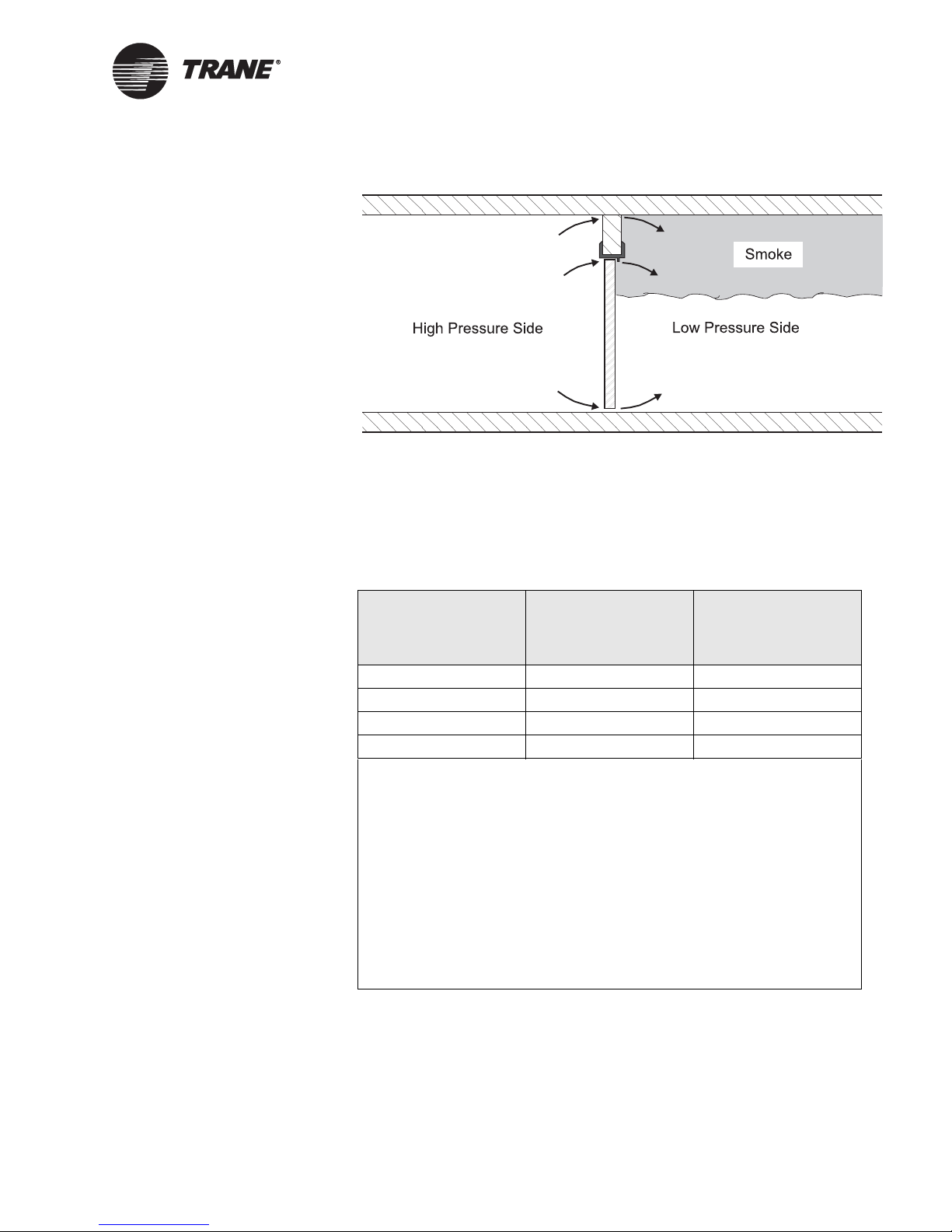
Pressurization method
The pressurization method protects refuge spaces and exit routes. The
method employs a pressure difference across a barrier to control smoke
movement (
either the refuge area or an exit route. The low-pressure side is exposed to
smoke. Airflow from the high-pressure side to the low-pressure side
(through construction cracks and gaps around doors) prevents smoke
infiltration. A path that channels smoke from the low-pressure side to the
outside ensures that gas expansion pressures do not become a problem. A
top-vented elevator shaft or a fan-powered exhaust can provide the path.
2 BAS-APG001-EN
Figure 1 on page 3). The high-pressure side of the barrier is
Page 15
Methods of smoke control
Figure 1: Sample pressure difference across a barrier
Table 1 provides the National Fire Protection Association (NFPA)
recommended minimum pressure difference between the high-pressure
side and the low-pressure side.
Table 1: Recommended minimum pressure difference
Building type
Sprinklered Any 0.05 (12.4)
Non-sprinklered 9 (2.7) 0.10 (24.9)
Non-sprinklered 15 (4.6) 0.14 (34.8)
Non-sprinklered 21 (6.4) 0.18 (44.8)
Notes:
Ceiling height
(ft [m])
Minimum pressure
difference
(In.w.c. [Pa])
• The minimum pressure difference column provides the pressure
difference between the high pressure side and the low-pressure side.
• The minimum pressure difference values incorporate the pressure
induced by the buoyancy of hot smoke.
• A smoke control system should maintain the minimum pressure
differences regardless of stack effect and wind.
• The minimum pressure difference values are based on
recommendations in NFPA 92A (NFPA 2000, Recommended Practice
for Smoke Control Systems).
• In.w.c. is inches of water column.
• Pa is Pascals.
Table 2 on page 4 provides the NFPA recommended maximum allowable
pressure difference across doors. The listed pressure differences take into
account the door closer force and door width.
BAS-APG001-EN 3
Page 16
Chapter 1 Smoke control overview
Table 2: Maximum allowable pressure differences across doors
Door width
(in. [m])
32 (0.813) 36 (0.914) 40 (1.02) 44 (1.12) 46 (1.17)
Door closer force
(lb. [N])
6 (26.7) 0.45 (112.0) 0.40 (99.5) 0.37 (92.1) 0.34 (84.6) 0.31 (77.1)
8 (35.6) 0.41 (102.0) 0.37 (92.1) 0.34 (84.5) 0.31 (77.1) 0.28 (69.7)
10 (44.5) 0.37 (92.1) 0.34 (84.5) 0.30 (74.6) 0.28 (69.7) 0.26 (64.7)
12 (53.4) 0.34 (84.5) 0.30 (74.6) 0.27 (67.2) 0.25 (62.2) 0.23 (57.2)
14 (62.3) 0.30 (74.6) 0.27 (67.2) 0.24 (59.7) 0.22 (45.7) 0.21 (52.2)
Notes:
Pressure difference
(In.w.c. [Pa])
• Total door opening force is 30 lb. (133 N); door height is 80 in. (2.03 m). NFPA 101 (NFPA 2003, Life
Safety Code) recommends the door opening force.
• N is Newton.
• m is meter.
• In.w.c. is inches of water column.
• Pa is Pascal.
• The pressure difference values are based on recommendations in NFPA 92A (NFPA 2000,
Recommended Practice for Smoke Control Systems).
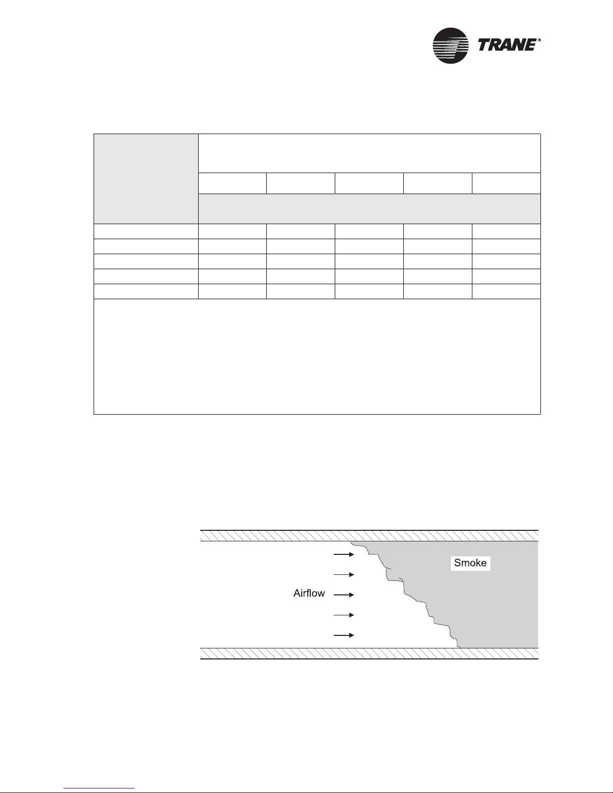
Airflow method
The airflow method controls smoke in spaces that have barriers with one
or more large openings. It is used to manage smoke in subway, railroad,
and highway tunnels. The method employs air velocity across or between
barriers to control smoke movement (
Figure 2).
Figure 2: Sample airflow method
4 BAS-APG001-EN
Page 17

Applications of smoke control methods
A disadvantage of the airflow method is that it supplies increased oxygen
to a fire. Within buildings, the airflow method must be used with great
caution. The airflow required to control a wastebasket fire has sufficient
oxygen to support a fire 70 times larger than the wastebasket fire. The
airflow method is best applied after fire suppression or in buildings with
restricted fuel. For more information on airflow, oxygen, and combustion,
refer to Huggett, C. 1980, Estimation of Rate of Heat Release by Means of
Oxygen Consumption Measurements, Fire and Materials.
Buoyancy method
The buoyancy method clears smoke from large volume spaces with high
ceilings. The method employs paths to the outside and relies on hot
combustion gases rising to the highest level in a space. At the high point,
either a powered smoke exhausting system or a non-powered smoke
venting system clears the smoke.
Applications of smoke control methods
Applying the methods of smoke control to spaces within a building
provides a building smoke control system. Smoke control methods are
most commonly applied to building spaces to provide zoned, stairwell,
elevator shaft, and atrium smoke control.
Note:
It is beyond the scope of this user guide to provide
mathematical design analysis information for smoke control.
For references to design analysis information, see
References.
Appendix A,
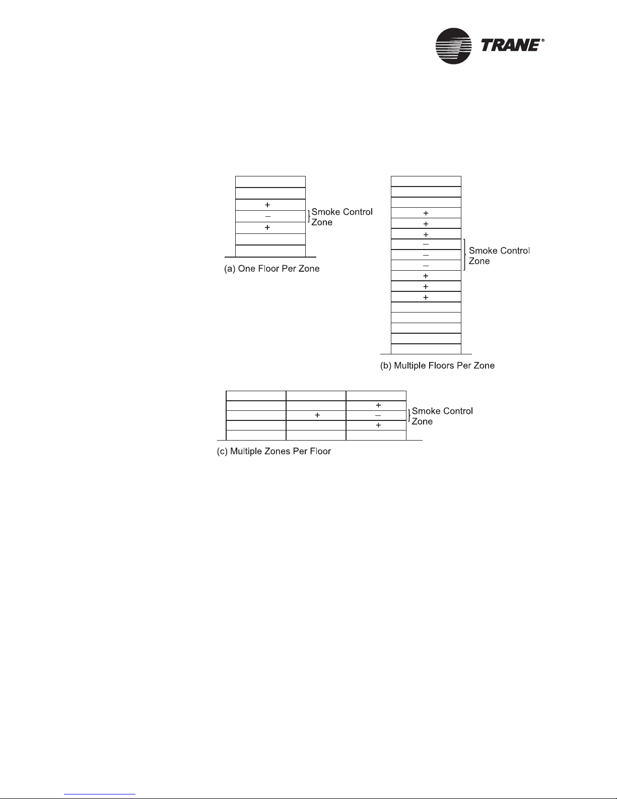
Zoned smoke control
Zoned smoke control uses compartmentation and pressurization to limit
smoke movement within a building. Typically, a building consists of a
number of smoke control zones. Barriers (partitions, doors, ceilings, and
floors) separate the zones. Each floor of a building is usually a separate
zone (
Figure 3 on page 6). However, a zone can consist of more than one
floor, or a floor can consist of more than one zone.
The zone in which the smoke is detected is the smoke control zone. Zones
next to the smoke control zone are adjacent zones. Zones not next to the
smoke control zone are unaffected zones.
Pressure differences produced by fans limit smoke movement to adjacent
and unaffected zones. The system may pressurize adjacent zones and
leave all unaffected zones in normal operation (Figure 3(a) and Figure
3(c),
page 6). Pressurizing adjacent zones creates a pressure sandwich.
Or, the system may pressurize adjacent zones and some unaffected zones
(Figure 3(b),
control zone, putting it at a negative pressure, relative to adjacent zones.
page 6). In either case, the system exhausts the smoke
BAS-APG001-EN 5
Page 18
Chapter 1 Smoke control overview
Zoned smoke control cannot limit the spread of smoke within the smoke
control zone. Consequently, occupants of the smoke control zone must
evacuate as soon as possible after fire detection.
Figure 3: Sample arrangements of smoke control zones
+ : Represents high-pressure zone
– : Represents low-pressure zone
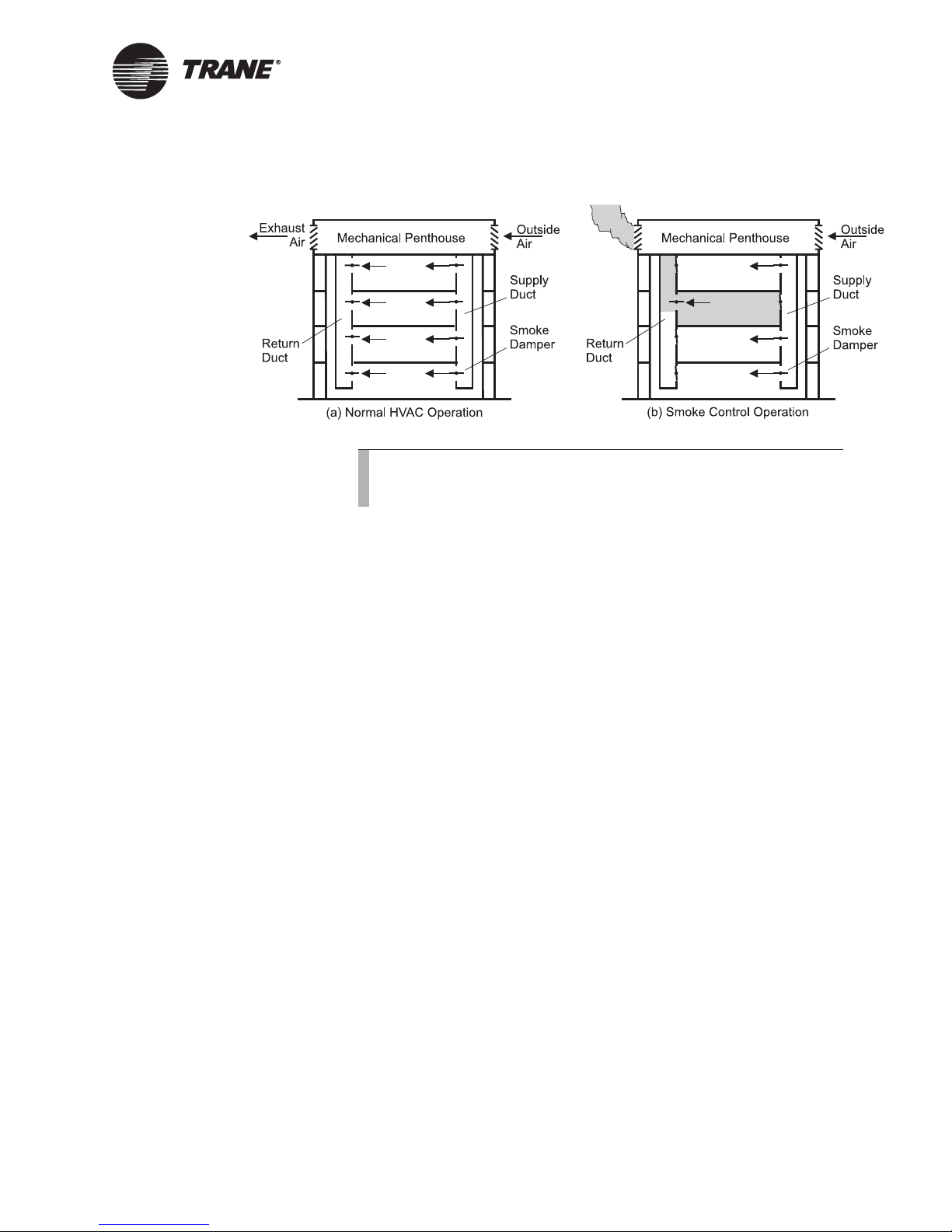
When an HVAC system serves multiple floors (Figure 4 on page 7) and
each floor is a separate zone, the following sequence provides smoke
control:
1. In the smoke control zone, the smoke damper in the supply duct
closes and the smoke damper in the return duct opens.
2. In adjacent and/or unaffected zones, the smoke dampers in the return
ducts close and smoke dampers in the supply ducts open.
3. If the system has a return air damper, it closes.
4. Supply and return fans activate.
6 BAS-APG001-EN
Page 19
Applications of smoke control methods
Figure 4: Sample HVAC operation during smoke control
Note:
For simplicity, Figure 4 does not show the ducts on each floor or
the penthouse equipment.
When an HVAC system serves only one smoke control zone, the following
sequence provides smoke control:
1. In the smoke control zone, the return/exhaust fan activates, the
supply fan deactivates.
2. The return air damper closes, and the exhaust damper opens
(optionally, the outside air damper closes).
3. In the no-smoke zone, the return/exhaust fan deactivates, the supply
fan activates.
4. The return air damper closes, and the outside air damper opens
(optionally, the exhaust air damper closes).
Stairwell smoke control
Stairwell smoke control uses pressurization to prevent smoke migration
through stairwells to floors remote from the source of the smoke.
Secondarily, it provides a staging area for fire fighters.
In the smoke control zone, a pressurized stairwell maintains a positive
pressure difference across closed stairwell doors to limit smoke
infiltration to the stairwell. Stairwell smoke control employs one or more
of these design techniques: compensated pressurization, noncompensated pressurization, single injection pressurization, and multiple
injection pressurization.
Compensated pressurization technique
The compensated stairwell pressurization technique adjusts air pressure
to compensate for various combinations of open and closed stairwell
access doors. The technique maintains constant positive pressure
differences across openings. To compensate for pressure changes, it either
employs modulated supply airflow or over-pressure relief.
BAS-APG001-EN 7
Page 20
Chapter 1 Smoke control overview
If the technique employs modulated supply airflow, a fan provides at least
minimum pressure when all stairwell access doors are open. Either a
single-speed fan with modulating bypass dampers or a variable frequency
drive varies the flow of air into the stairwell to compensate for pressure
changes.
If the technique employs over-pressure relief, a damper or fan relieves air
to the outside to maintain constant pressure in the stairwell. The amount
of air relieved depends on the air pressure in the stairwell. A barometric
damper, a motor-operated damper, or an exhaust fan can be used to
maintain the air pressure.
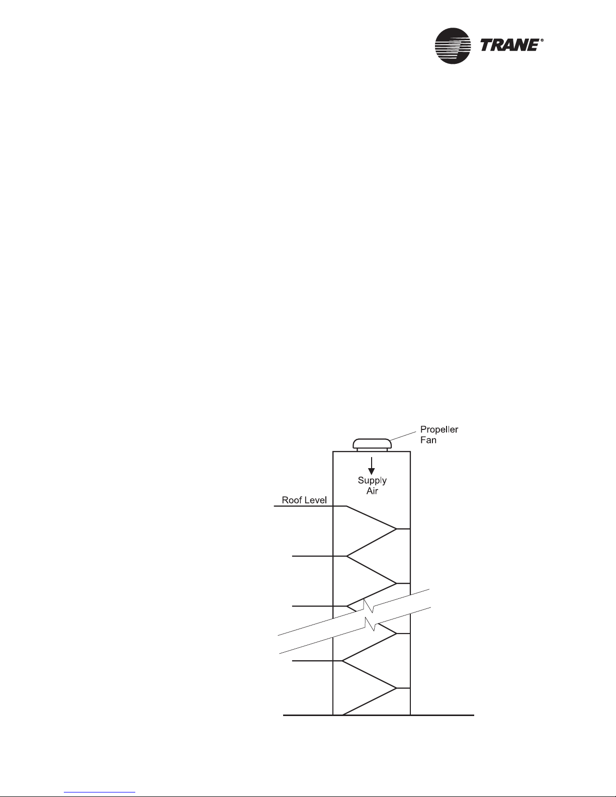
Non-compensated pressurization technique
The non-compensated pressurization technique provides a constant
volume of pressurization air. The level of pressurization depends on the
state of the stairwell access doors. When access doors open, the pressure
in the stairwell lowers. When access doors close, the pressure raises. One
or more single-speed fans provide pressurization air (
Non-compensated stairwell pressurization works best when:
Figure 5).
• Stairwells are in a lightly populated building (for example: telephone
exchanges and luxury apartments).
• Stairwell access doors are usually closed, but when used, remain open
only a few seconds.
Figure 5: Sample non-compensated system
8 BAS-APG001-EN
Page 21
Applications of smoke control methods
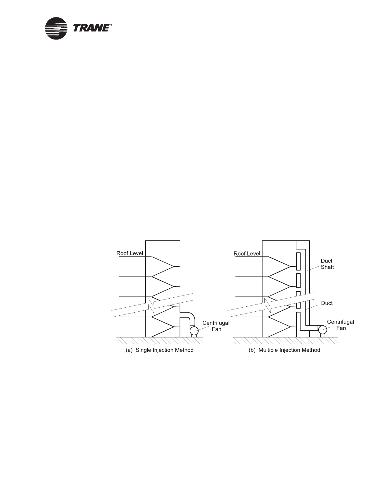
Single and multiple injection pressurization techniques
The single injection and multiple injection techniques provide
pressurization air to a stairwell (
more pressurization fans located at ground level, roof level, or any
location in between.
The single injection technique supplies pressurization air to the stairwell
from one location.
Figure 6). Both techniques use one or
IMPORTANT
The single injection technique can fail when stairwell access doors are
open near the air supply injection point. Pressurization air will escape
and the fan will fail to maintain a positive pressure difference across
access doors farther from the injection point.
The multiple injection technique supplies pressurization air to the
stairwell from more than one location. When access doors are open near
one injection point, pressurization air escapes. However, other injection
points maintain positive pressure differences across the remaining access
doors.
Figure 6: Sample single and multiple injection methods
Elevator shaft smoke control
Elevator shaft smoke control uses pressurization to prevent smoke
migration through elevator shafts to floors remote from the source of the
smoke. Elevator shaft smoke control is similar to stairwell smoke control.
The stairwell pressurization techniques described previously are
applicable to elevator shaft pressurization.
BAS-APG001-EN 9
Designating an elevator as a fire exit route is an acceptable, though not
typical, practice. NFPA 101 (NFPA 2003, Life Safety Code) allows
elevators to be second fire exit routes from air traffic control towers. For
Page 22
Chapter 1 Smoke control overview
more information about elevator shaft smoke control, refer to Klote, J.K.,
and Milke, J.A. (Design of Smoke Management Systems, 1992).
Atrium smoke control
Atrium smoke control uses buoyancy to manage smoke in large-volume
spaces with high ceilings. The buoyancy of hot smoke causes a plume of
smoke to rise and form a smoke layer under the atrium ceiling. NFPA
92B (NFPA 2000, Guide for Smoke Management Systems in Malls, Atria,
and Large Areas) addresses smoke control for atria, malls, and large
areas. Atrium smoke control techniques consist of smoke exhausting,
natural smoke venting, and smoke filling.
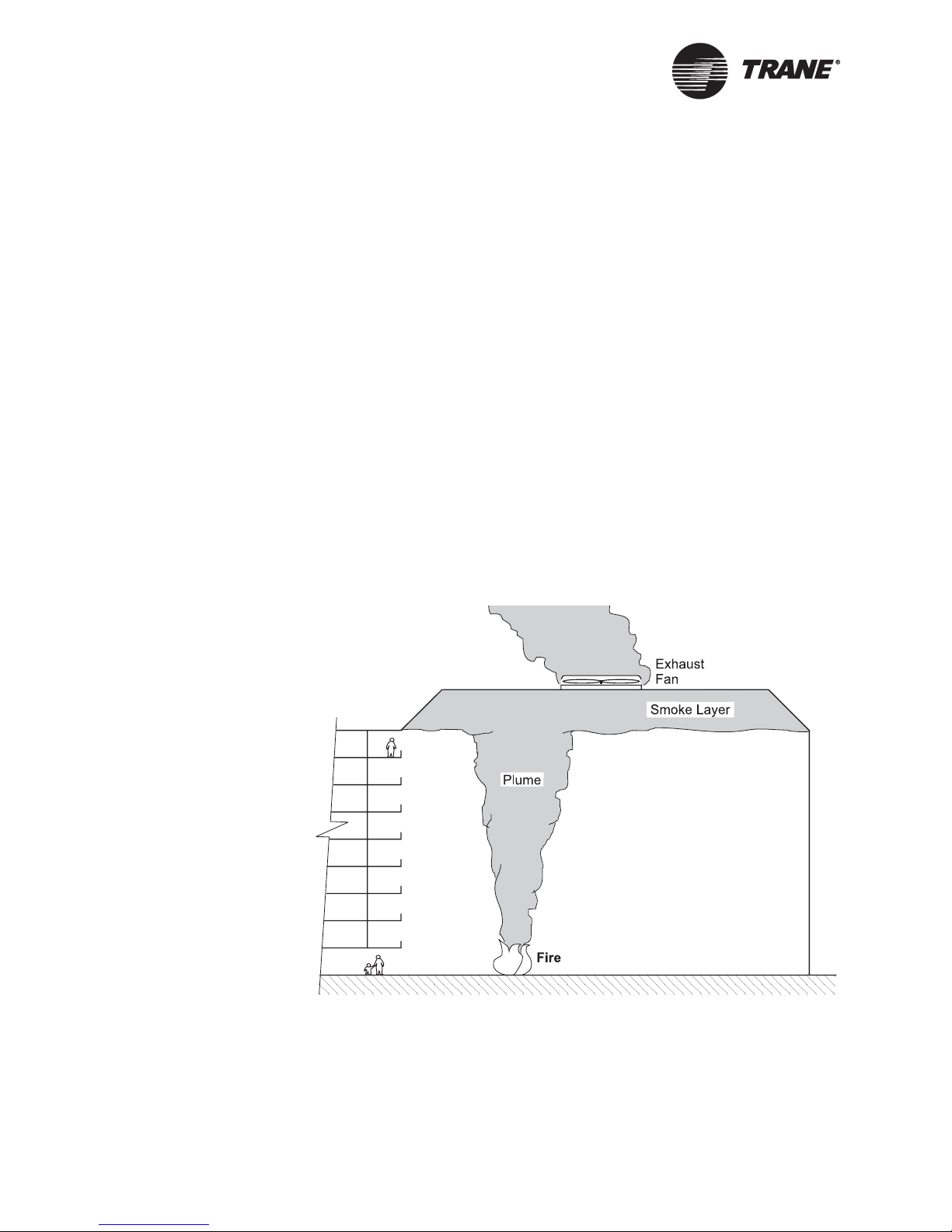
Smoke exhausting technique
The smoke exhausting technique employs fans to exhaust smoke from the
smoke layer under the ceiling. Exhausting prevents the smoke layer from
descending and coming into contact with the occupants of the atrium
(
Figure 7). Effective smoke removal requires providing makeup air to the
space. Makeup air replaces the air that is exhausted by the fans. If
makeup air is not introduced, the space will develop a negative pressure,
which will restrict smoke movement.
Figure 7: Sample atrium smoke exhausting technique
10 BAS-APG001-EN
Page 23
Applications of smoke control methods
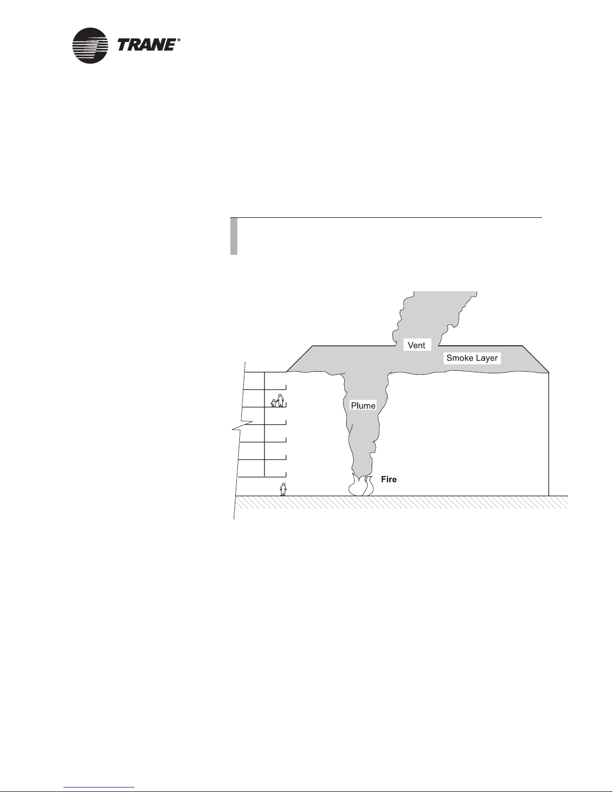
Natural smoke venting technique
The natural smoke venting technique employs vents in the atrium ceiling
or high on the atrium walls to let smoke flow out without the aid of fans
(
Figure 8). The applicability of natural venting depends primarily on the
size of the atrium, the outside temperature, and the wind conditions.
When smoke is detected, all vents open simultaneously. The flow rate
through a natural vent depends on the size of the vent, the depth of the
smoke layer, and the temperature of the smoke.
Note:
Thermally activated vents are not appropriate for natural
venting because of the time delay for opening.
Figure 8: Sample natural smoke venting technique
BAS-APG001-EN 11
Smoke filling technique
The smoke filling technique allows smoke to collect at the ceiling. Without
fans to exhaust the smoke, the smoke layer grows thicker and descends.
Atrium smoke filling is viable when an atrium is of such size that the
time needed for the descending smoke to reach the occupants is greater
than the time needed for evacuation.
People movement calculations determine evacuation time. For
information on people-movement calculations, refer to SFPE 1995, Fire
Protection Engineering Handbook.
Page 24

Chapter 1 Smoke control overview
Underground building smoke control
The smoke control objective for underground buildings is to contain and
remove smoke from the alarm zone. The smoke control system fully
exhausts the alarm zone and provides makeup air to replace the
exhausted air.
Setup and zoning of the smoke detectors is part of the fire alarm system
engineering effort. The fire alarm system signals the smoke control
system to start automatic smoke control operations.
In NFPA 101 (NFPA 2003, Life Safety Code), chapter 11.7 states that an
underground building with over 100 occupants must have an automatic
smoke venting system. Chapter 14.3, for new educational occupancies,
provides smoke zoning requirements. Chapter 12.4.3.3 states that
automatic smoke control must be initiated when two smoke detectors in a
smoke zone activate. Chapter 12.4.3.3 states that the system must be
capable of at least 6 air changes per hour.
Smoke detection and system activation
The appropriate smoke detection and system activation approach
depends on the specifics of the smoke control system and on the code
requirements. Automatic activation has the advantage over manual
activation. Automatic activation provides fast and accurate response.
Each smoke control application has detection and activation
requirements:
• Zoned smoke control
• Stairwell smoke control
• Elevator smoke control
• Atrium smoke exhaust
12 BAS-APG001-EN
Note:
Smoke detectors located in HVAC ducts should not be the
primary means of smoke control activation. Duct detectors have
long response times and exhibit degraded reliability when
clogged by airborne particles. However, a duct detector signal
may be used in addition to a primary means of activation. For
more information, refer to Tamura, G.T., Smoke Movement &
Control in High-Rise Buildings.
Page 25

Smoke detection and system activation
Zoned smoke control detection and activation
Zoned smoke control activation occurs on a signal from either a sprinkler
water flow switch or a heat detector. For maximum benefit, the zoned
smoke control system should only respond to the first alarm. Two design
techniques that prevent detection of smoke in zones other than the first
zone reporting are:
• Not activating smoke control on smoke detector signals
• Activating smoke control on signals from two separate smoke
detectors located in the same zone
Note:
Zoned smoke control should not activate on a signal from a
manual pull station (pull box). If pull box activation does not
occur in the zone that contains the fire, activation incorrectly
identifies the smoke zone.
Stairwell smoke control detection and activation
Stairwell smoke control activation occurs on an alarm signal from any
device, including sprinkler water flow switches, heat detectors, smoke
detectors, and manual pull stations (pull boxes). Most stairwell smoke
control systems operate in the same manner regardless of the source of
the alarm signal.
Elevator smoke control detection and activation
Elevator smoke control activation occurs on an alarm signal from any
device, including sprinkler water flow switches, heat detectors, smoke
detectors, and manual pull stations (pull boxes). Most elevator smoke
control systems operate in the same manner regardless of the source of
the alarm signal.
Note:
The description of elevator smoke control detection and
activation does not apply to pressurization systems for
elevators intended for occupant evacuation.
Atrium smoke exhausting detection and activation
Atrium smoke exhausting activation occurs on a signal from a beam
smoke detector. A beam smoke detector consists of a light beam
transmitter and a light beam sensor. Typically, the transmitter and the
sensor are located apart from each other. However, when located together,
the transmitter sends its beam to the opposite side of the atrium. At the
opposite side, the beam reflects back to the sensor.
Note:
Atrium smoke control should not activate on a signal from a
manual pull station (pull box). Atrium smoke exhaust systems
have different operating modes depending on fire location.
BAS-APG001-EN 13
Page 26
Chapter 1 Smoke control overview
Note:
Atrium smoke control should not activate on signals from
sprinkler water flow switches or heat detectors. Since the
temperature of a smoke plume decreases with height,
activation by these devices may not provide reliable results.
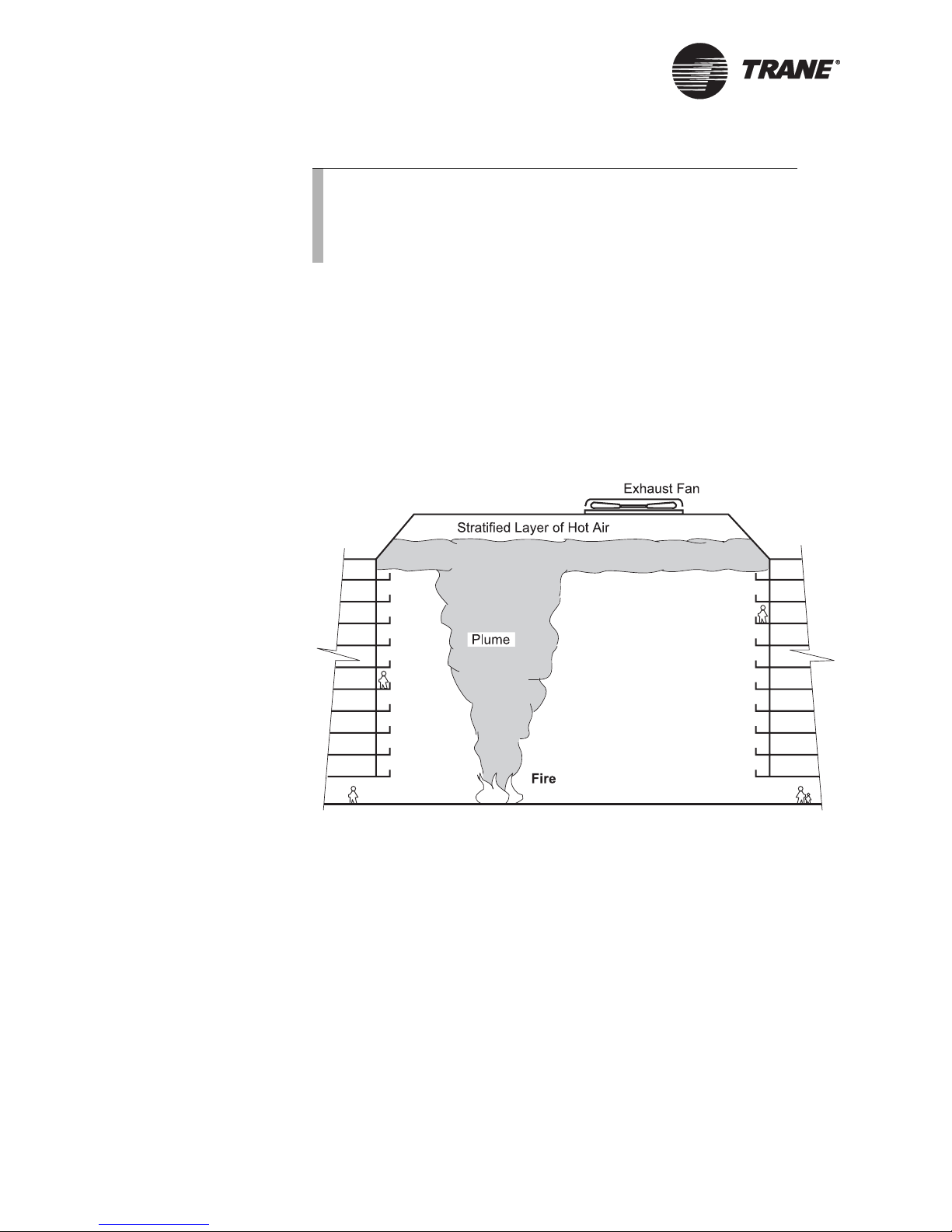
Beam smoke detectors minimize interference problems created by
stratified hot air under atrium ceilings. On hot days or days with a high
solar load on the atrium roof, a hot layer of air may form under the
ceiling. The layer can exceed 120
fire may not be hot enough to penetrate the layer and reach ceilingmounted smoke detectors (
Beam-detector installation typically conforms to one of two
configurations: vertical grid or horizontal grid.
Figure 9: Sample stratification
° F (50° C). The smoke from an atrium
Figure 9).
Vertical grid
The vertical grid is the most common beam detector configuration. A
number of beam detectors, located at different levels under the ceiling,
detect the formation and thickening of a smoke layer. The bottom of the
grid is at the lowest expected smoke stratification level.
Horizontal grid
The horizontal grid is an alternate beam detector configuration A number
of beam detectors, located at different levels under the ceiling, detect the
rising smoke plume. Beam detectors are located:
• Below the lowest expected smoke stratification level
• Close enough to each other to ensure intersection with the plume
14 BAS-APG001-EN
Page 27

Design approaches to smoke control
Design approaches to smoke control
Smoke control methods provide a mechanical means of directing smoke
movement in an enclosed space. The application of one or more methods
to a building provides a building smoke control system. Design
approaches to smoke control include the no smoke, tenability, and
dedicated system approaches.
No-smoke approach
The no-smoke approach provides a smoke control system that prevents
smoke from coming into contact with people or property. Almost all smoke
control systems are based on the no-smoke approach.
While the objective is to eliminate all smoke, some smoke occurs in
protected spaces. By molecular diffusion, minute quantities of smoke
travel against pressurization and airflow. These very low concentrations
of airborne combustion products are detected by their odor. These and
higher levels of diffused contaminants may not result in high-risk
conditions.
Tenability approach
The tenability approach provides a smoke control system that allows
smoke to come into contact with occupants. However, in this approach,
the smoke control system dilutes the by-products of combustion before
they come into contact with people. In atria applications, the natural
mixing of air into a smoke plume can result in significant dilution.
Tenability criteria vary with the application but may include:
• Exposure to toxic gases
• Exposure to heat
• Visibility
Dedicated system approach
The dedicated system approach, such as stairwell and elevator smoke
control, provides a system that has the sole purpose of managing smoke.
It does not function during normal building comfort control.
The advantages of the dedicated system approach include:
• The interface is simple, since there are few components to bypass.
• Modification of controls after installation is unlikely.
• Easy operation and control.
• Limited reliance on other building systems.
The disadvantages of the dedicated system approach include:
• Component failures may go undiscovered since they do not affect
normal building comfort control.
• Building systems may require more physical space.
BAS-APG001-EN 15
Page 28
Chapter 1 Smoke control overview
Design considerations for smoke
control
Two occurrences will hinder smoke control:
• Plugholing
• Smoke feedback
Smoke control systems should be designed to address the problems that
are caused by plugholing and smoke feedback.
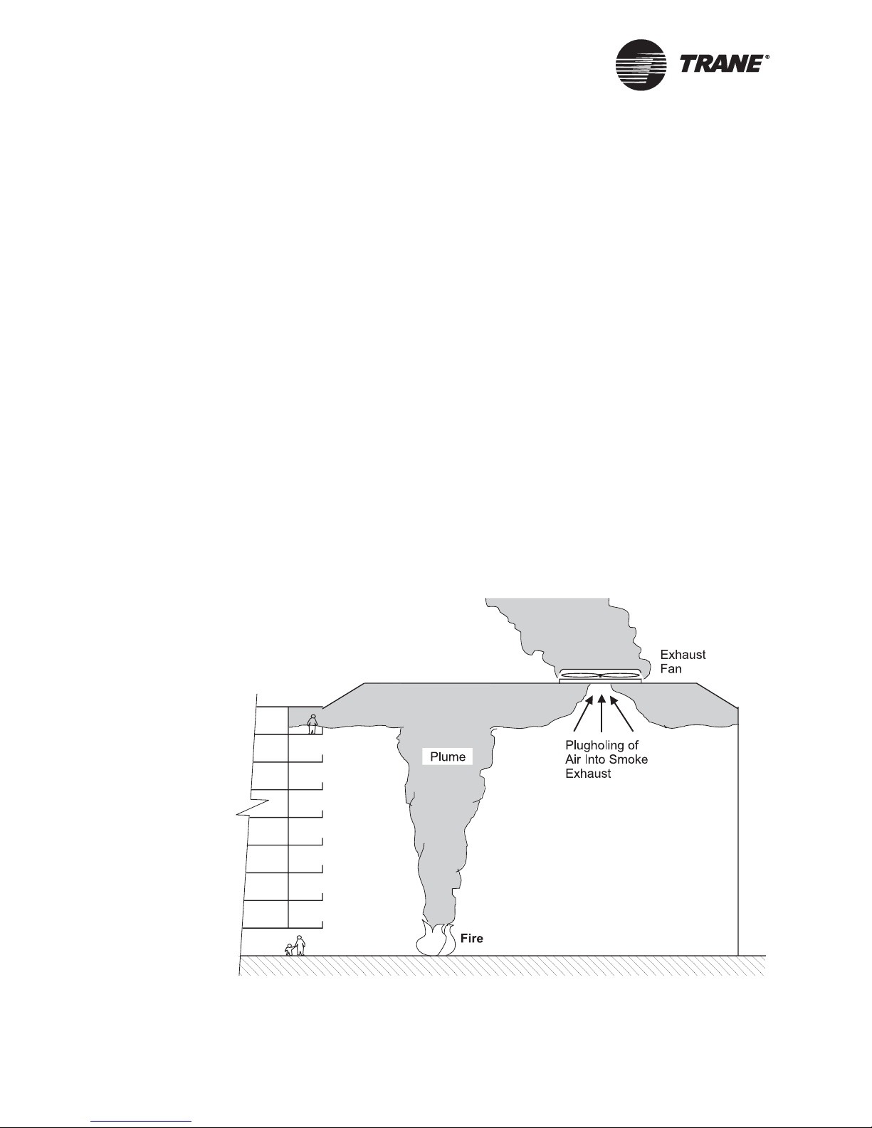
Plugholing
Plugholing occurs when an exhaust fan pulls fresh air into the smoke
exhaust (
increases the smoke layer depth. It has the potential of exposing
occupants to smoke.
The maximum flow of smoke (Q
depends on the depth of the smoke layer and the temperature of the
smoke. If the required total smoke exhaust is greater than Q
additional exhaust vents will eliminate plugholing. The distance between
vents must be great enough that the air and smoke flow near one vent
does not affect the air and smoke flow near another vent.
Figure 10). Plugholing decreases the smoke exhaust and
) exhausted without plugholing
max
,
max
Figure 10: Sample plugholing
16 BAS-APG001-EN
Page 29

Design considerations for smoke control
Smoke feedback
Smoke feedback occurs when smoke enters a pressurization fan intake
and flows into protected spaces. Design techniques reduce the probability
of smoke feedback:
• Supply air intakes located below openings from which smoke might
flow, such as building exhausts, smoke shaft outlets and elevator
vents.
• Automatic shutdown capability to stop the system in the event of
smoke feedback.
For more information on smoke feedback, refer to SFPE 1995, Fire
Protection Engineering Handbook.
BAS-APG001-EN 17
Page 30

Chapter 1 Smoke control overview
18 BAS-APG001-EN
Page 31

Chapter 2
Pre-installation
considerations
This chapter provides considerations that must be given prior to
installing an engineered smoke control system. The pre-installation
considerations are:
• Zone operating modes
• Associated equipment
• Equipment supervision
• System testing
• Alarm response
• Automatic smoke control matrix
• Response times
Note:
In this chapter, the application of the smoke control system as a
zoned system is for general practice and conforms to national
codes and publications. In all cases, the local authority having
jurisdiction (AHJ) has the authority to modify requirements.
IMPORTANT
The local AHJ must approve the proposed system before installation
begins.
Zone operating modes
Zone operating modes are a pre-installation consideration. The design of
a building smoke control system is the responsibility of the building
architects and engineers. In the National Fire Protection Association
(NFPA) publication NFPA 101 (NFPA 2003, Life Safety Code), chapter
11.8 provides general high rise building requirements. Chapter 12–42
provides high-rise building requirements based on type of occupancy.
Both chapters may apply to a specific building.
Understanding the smoke control system operating modes enables the
effective layout of system controls. One of four operating modes governs
each zone: normal, alarm, adjacent, or unaffected.
BAS-APG001-EN 19
Page 32

Chapter 2 Pre-installation considerations
Normal mode
A zone is in normal mode when no fire, smoke, or sprinkler alarms are
present in the building. In some zoning systems, a zone may be in normal
mode if an alarm condition is present in the building but the zone is not
affected. In normal mode, the smoke control system is inactive.
Alarm mode
A zone is in alarm mode when it is the origin of the first fire, smoke, or
sprinkler alarm. In alarm mode, the smoke control system operates fans
and dampers to protect adjacent and unaffected zones and provide a
smoke exhaust route for the alarm zone.
Adjacent mode
A zone is in adjacent mode when it is next to the alarm zone. However, in
some zoning systems, zones that are not next to the alarm zone may be
designated as adjacent zones. Other zoning systems may designate all
non-alarm zones as adjacent zones. Codes do not state which zones are
adjacent. In adjacent mode, the smoke control system sets fans and
dampers to pressurize adjacent zones in order to contain the smoke in the
alarm zone.
Unaffected mode
A zone is in unaffected mode when it is neither the alarm zone nor an
adjacent zone and an alarm is present in the building. In large buildings,
there may be many zones that are not near the alarm zone. Codes do not
state which zones are unaffected. In unaffected mode, the smoke control
system may shut down and isolate unaffected zones. Or, the smoke
control system may allow unaffected zones to operate in normal mode.
Actual system operation depends on the design of the smoke control
system.
Associated equipment
Equipment associated with the smoke control system design is a preinstallation consideration prior to setting up the smoke control system
controls. Associated equipment includes: fire alarm system equipment,
fire alarm control panel, firefighter’s smoke control station, and smoke
control system equipment.
Fire alarm system equipment
The building fire alarm system is responsible for detecting an alarm
condition, alerting occupants by audible and visual means, and signaling
the smoke control system. Fire alarm system equipment includes: area,
20 BAS-APG001-EN
Page 33

Associated equipment
beam, and duct smoke detectors; manual pull stations; and sprinkler flow
devices.
Note:
Fire alarm system equipment is neither furnished nor installed
by Trane.
Area smoke detectors
Area smoke detectors detect the presence of smoke at the ceiling. When
activated, an area smoke detector signals the fire alarm system. The
zoning of area smoke detectors must reflect the zoning of the building.
Note:
Under certain conditions, heat detectors or heat with rate of
rise detectors are preferable to area smoke detectors.
Beam smoke detectors
Beam smoke detectors detect the presence of smoke beneath the ceiling.
When activated, a beam smoke detector signals the fire alarm system. In
atrium applications, beam detectors may replace area smoke detectors.
Beam smoke detectors minimize interference problems created by
stratified hot air under the atrium ceiling.
Duct smoke detectors
Duct smoke detectors detect smoke in building air-distribution system
ductwork. When smoke is present, a signal from the detector deactivates
the fans in the system in which the detector is installed. However, smoke
control system commands must override fan deactivation by a duct smoke
detector.
In NFPA 90A (NFPA 2002, Standard for the Installation of Air
Conditioning and Ventilating Systems), section 6.4.2.1 provides the
requirements for duct smoke detectors. Supply duct smoke detectors must
be located downstream of the system filters and ahead of any branch
connection. In mixing systems, this is usually after the return air
connection. Duct smoke detectors may be required in the supply duct of
all air-handling systems greater than 2000 cubic feet per minute (CFM)
and at each floor with a return air volume greater than 15,000 CFM.
Two exceptions limit the use of duct smoke detectors:
• Duct smoke detectors are not required in 100% exhaust air systems.
• Duct smoke detector use is limited if area smoke detectors cover the
entire space served by the return air distribution. Since area smoke
detectors usually cover entire floors, the typical system only requires
one duct smoke detector in the common return duct.
Manual pull stations
Manual pull stations enable occupants to report a fire. When activated, a
manual pull station signals the fire alarm system. A manual pull station
alarm must not initiate the automatic operation of the smoke control
BAS-APG001-EN 21
Page 34

Chapter 2 Pre-installation considerations
system, since a pull station is not necessarily activated in the zone that
contains the smoke or fire.
Sprinkler flow devices
Fire alarm system equipment may include two types of sprinkler flow
devices: sprinkler flow switches and tamper switches.
Sprinkler flow switches, installed in fire sprinkler lines, notify the fire
alarm control panel (FACP) of flow in the sprinkler lines. The FACP
transmits an alarm to the smoke control system. The smoke control
system may initiate automatic smoke control from the alarm. Sprinkler
zones must coincide with the zone layout of the building and the zoning of
the FACP.
Tamper switches are installed on manual shutoff valves in the fire
sprinkler system. The switches provide a supervisory alarm signal to the
fire alarm system if the shutoff valve closes. Alarms activated by tamper
switches must not initiate the automatic operation of the smoke control
system.
Fire alarm control panel
The FACP receives alarm signals. If the FACP receives an alarm, it
notifies the smoke control system of the alarm and the alarm location.
The zone layout of the FACP must match the zone layout of the building
to ensure that the FACP is capable of sending accurate signals to the
smoke control system. The mechanical and electrical consulting engineers
coordinate the building zone layout to the FACP layout to ensure a proper
interface.
Firefighter’s smoke control station
The firefighter’s smoke control station (FSCS) enables firefighters to take
manual control of the smoke control system. The FSCS must be located in
an easily accessible but secure location. The normal location is near the
FACP.
IMPORTANT
The FSCS must be listed by Underwriters Laboratories (UL) as suitable
for enabling firefighters to take manual control of the smoke control
system.
Commands from the FSCS control panel are the highest priority
commands in the system. They override automatic control of smoke
control system components.
The FSCS provides a graphic representation of the building. It shows
smoke control zones and associated smoke control mechanical equipment.
The panel includes: lights, an audible trouble LED, and manual switches.
22 BAS-APG001-EN
Page 35

Associated equipment
Lights
The FSCS provides lights that show the mode of each zone and the status
of each piece of smoke control mechanical equipment. The status lights
must conform to a specific color code scheme (
Table 3).
Table 3. Pilot lamp color codes
Color Description
Green Fan On or damper Open
Red Fan Off or damper Closed
Yellow (or Amber) Verification of Operation Status light. Fan or
damper not in commanded position.
Audible trouble indicator
The FSCS may provide an audible trouble indicator with a silence switch.
If provided, the indicator alerts personnel to system trouble.
Manual switches
The FSCS provides manual switches that operate smoke control system
fans and dampers. Normally, there is one manual switch for each piece of
equipment. However, in complex smoke control systems that have very
large fan systems, one switch may operate more than one piece of
equipment. This allows the smoke control system to coordinate smoke
control functions without damaging equipment. For example, the manual
switches that control large central fan systems may also operate the
mixing dampers to prevent tripping the high- and low-pressure cutouts.
Manual switches at the FSCS are either 2- or 3-position switches. Labels
show the current state of each switch (
Table 4).
BAS-APG001-EN 23
Table 4. Switch state descriptions
Switch state Equipment
ON-AUTO-OFF Fans controlled by the smoke control system or
other automatic control system
OPEN-AUTO-CLOSE Dampers controlled by the smoke control
system or other automatic control system
ON-OFF Fans only controlled from the FSCS
OPEN-CLOSE Dampers only controlled from the FSCS
Smoke control system equipment
The smoke control system receives alarm signals from the FACP and
manual command signals from the FSCS. On receiving alarm signals
and/or manual commands, the smoke control system controls the
mechanical smoke control equipment. Manual command signals from the
FSCS take priority over alarm signals.
Page 36

Chapter 2 Pre-installation considerations
The smoke control system controls fans and positions dedicated and
nondedicated dampers, both in the smoke control zones and at the airhandling systems. It may also position dampers or air modulation devices
such as variable-air-volume (VAV) boxes serving the smoke control zones.
Equipment associated with the smoke control system includes: dampers,
fans, verification of operation equipment, and the Tracer™ MP581
programmable controller.
For VAV-based systems, there must be some form of duct pressure relief
on each floor or in each smoke control zone. In smoke control mode, all
return and supply dampers will be set to 100% open. If the VAV dampers
are closed when this occurs, the duct pressure may be enough to damage
duct work. To avoid this possibility, duct pressure relief dampers, either
DDC or mechanically controlled, should be installed in the ductwork for
each smoke control zone.
It should be noted that careful sizing of smoke control supply air damper
and relief damper is necessary to use smoke purge and protect dampers.
In contrast to a VAV system, it is not necessary to provide separate duct
pressure relief in constant volume as this is a form of dedicated smoke
purge with supply and return/exhaust dampers already open. Supply
dampers should be sized such that any one damper can spill an adequate
amount of air.
Outdoor air, return air, relief, and exhaust dampers
A nondedicated comfort control system controls outdoor air, return air,
relief, and exhaust dampers. In normal operation, the return damper
operates in opposition to the outdoor air damper. However, during smoke
control system activation, all three dampers may be closed
simultaneously to isolate the air-handling system for smoke control
operations.
An elevator shaft damper, located at the top of a hoistway, relieves
pressure generated during elevator operation. Since elevator shaft
dampers are usually open, the natural stack effect of the building will
tend to distribute smoke through the building via the elevator shafts.
Some codes require a key-operated switch at the main floor lobby to close
the elevator shaft damper. With local approval, this switch can be located
at the FSCS.
Smoke dampers
A smoke damper is located in any duct that penetrates a smoke zone
perimeter. Smoke dampers that are listed by Underwriters Laboratories
(UL) are subject to more stringent leakage tests than are standard
control dampers. The listing usually includes the control actuator as part
of the smoke damper assembly, but does not include the end switches.
IMPORTANT
Smoke dampers must have a Underwriters Laboratories (UL) listing for
smoke control applications (UL 555S).
24 BAS-APG001-EN
Page 37

Associated equipment
Smoke dampers are ordered as a complete assembly. They are typically
two-position dampers and have end switches that indicate the fully open
and fully closed position. The switches are installed in the field. Dampers
actuate with two types of control: pneumatic actuation and electrical
actuation.
Note:
Switches that are part of the actuator do not provide an
acceptable indication of actual damper travel. They only show
the operation of the actuator and not the actual position of the
damper.
For pneumatically actuated smoke dampers, the operating pressure
range (spring range) and the normal position of the damper must be
specified. Typically, the normal position will be closed (normally closed).
The spring range must be high (8–13 lbs) to give the most close-off force.
Uniform Building Code 905.10.2 requires hard drawn, type L, copper
pneumatic piping for smoke control system components. The air source
must have automatic isolation valves separating it from pneumatic
control devices not used for smoke control. Since the smoke control
system will open and close smoke dampers, it may require an air pressure
monitoring switch. If air pressure is lost in the smoke damper control
lines, the switch transmits a Trouble indication.
For electrically actuated smoke dampers, the operating voltages are
24
Vac a nd 12 0 Vac. It is usually not possible to get actuators with DC
operating voltages. A spring on the actuator positions the damper if
power is lost. The power-loss position is typically the actuator closed
(normally closed) position.
The electrical power that operates the smoke damper must be from an
emergency power source and is monitored at a point after the last
disconnect. The loss of electrical power initiates a Trouble indication.
BAS-APG001-EN 25
Fans
Fans need additional control components for smoke control operation.
Supply/return fan systems require independent control of fans. Multiple
fan system Start and Stop points bypass some safety devices.
VAV systems require the smoke control system to be capable of either
commanding the fans to full capacity or a higher capacity than comfort
controls would command. High-pressure safeties are not bypassed in
smoke control operation. Care must be taken to ensure that increased
capacities do not trip high-pressure cutout devices. Excess pressures
could deactivate fan systems, making them unusable for smoke control.
Verification of operation equipment
Codes require that the smoke control system provide verification of
operation status indications at the FSCS. To accomplish this, the smoke
control system provides devices that monitor the actual operation of fans
Page 38

Chapter 2 Pre-installation considerations
and dampers: status switches, differential pressure switches, airflow
paddle switches, current-sensing relays, limit switches, and end switches.
Status switches at fans and dampers monitor the operation of the devices.
Multiple binary inputs at the Tracer MP581s verify the On and Off status
of fans and the Open and Closed status of dampers. If a status switch
does not confirm the commanded (automatic or manual) operation, a Fail
indicator activates at the FSCS. Failure detection must incorporate a
time delay to give the devices time to function.
Differential pressure switches, airflow paddle switches, and currentsensing relays monitor fan operations. Differential switches piped across
fan and paddle switches in the air stream can give erroneous indications.
IMPORTANT
A current-sensing relay is the preferred way to confirm the operating
status of a fan.
Limit switches and end switches monitor dampers. The switches activate
damper Open and Closed signals for the FSCS. The damper blades
activate the switches. Some codes require two switches in order to sense
both the fully opened and fully closed position of the damper.
Tracer MP581 programmable controller
The Tracer MP581 must have multiple binary inputs to verify the On and
Off operation of fans. It must also have multiple binary inputs to verify
the Open and Closed positions of dampers.
Equipment supervision
Equipment supervision is a pre-installation consideration. Smoke control
equipment must be supervised to ensure it is operational. Supervision
techniques consist of confirming communications among system control
panels, confirming operation in normal use situations, and performing
weekly self-tests.
Confirming communications among all system control panels is a
supervision technique that monitors basic system integrity. If any panel
loses its communications, a Trouble alert is sent to the FSCS.
Normal use operations confirm the integrity of field point wiring for
nondedicated equipment. Nondedicated equipment provides conditioned
air to the building daily. When nondedicated equipment is not
operational, comfort conditions deteriorate and building tenants notify
maintenance personnel.
26 BAS-APG001-EN
Page 39

System testing
System testing
System testing is a pre-installation consideration. To verify proper
operation, the smoke control system must include provisions for:
automatic weekly self-testing and manual periodic testing.
Automatic weekly self-testing
As UL requires, the smoke control system provides automated weekly
self-tests for dedicated smoke control system components. The self-tests
activate components and monitor operation. They provide verification of
operation status indications to the FSCS that show if the component
passed or failed the test. Automatic weekly self-tests do not function if a
smoke or fire alarm is present.
Manual periodic testing
As NFPA 92A (NFPA 2000, Recommended Practice for Smoke Control
Systems), chapter 5.4 requires, the smoke control system provides a
manual testing capability. It provides annual tests for nondedicated
system components and semi-annual tests for dedicated system
components. The semi-annual tests are required in addition to the
automated weekly self-tests for dedicated smoke control system
components. Building maintenance personnel schedule and conduct the
tests.
The manual periodic tests verify smoke control system responses to alarm
zone inputs. Some of the manual testing must be performed with the
system operating on emergency power, if applicable. An alarm must be
generated in each zone. The system and equipment responses must be
verified and recorded. Manual periodic testing should occur when the
building is not occupied.
BAS-APG001-EN 27
Alarm response
Alarm response is a pre-installation consideration. NFPA 92A (NFPA
1996, Recommended Practice for Smoke Control Systems), section 3.4.5.5
requires the automatic response to an alarm to be based on the location of
the first alarm. Subsequent alarms from other zones must be ignored for
the purposes of automatic response.
Automatic smoke control matrix
An automatic smoke control matrix (Table 5 on page 28, dedicated;
Table 6 on page 28, nondedicated) shows each piece of mechanical
equipment and each building zone. The matrix shows the automatic
response of each piece of equipment to an initial alarm for each smoke
zone. It also shows the mode of each zone based on an alarm in another
zone. Commands from the FSCS may override the automatic responses.
The matrix must be engineered for a specific project.
Page 40

Chapter 2 Pre-installation considerations
Table 5. Sample automatic smoke control matrix (dedicated)
Equipment
Zone 1 Zone 2 Zone 3 Zone 4
Main sup fan On On On On
Main R/E fan On On On On
Stair press fan On On On On
1st flr sup dmpr Close Open Close Close
1st flr ret dmpr Open Close Close Close
2nd flr sup dmpr Open Close Open Close
2nd flr ret dmpr Close Open Close Close
3rd flr sup dmpr Close Open Close Open
3rd flr ret dmpr Close Close Open Close
4th flr sup dmpr Close Close Open Close
4th flr ret dmpr Close Close Close Open
Smoke zone 1 Alarm Adjacent Unaffected Unaffected
Smoke zone 2 Adjacent Alarm Adjacent Unaffected
Smoke zone 3 Unaffected Adjacent Alarm Adjacent
Smoke zone 4 Unaffected Unaffected Adjacent Alarm
First smoke zone in alarm
Table 6. Sample automatic smoke control matrix (nondedicated)
Equipment
Zone 1 Zone 2 Zone 3 Zone 4
Main sup fan On On On On
Main R/E fan On On On On
Stair press fan On On On On
1st flr sup dmpr Open Open Open Open
1st flr ret dmpr Open Open Open Open
2nd flr sup dmpr Open Open Open Open
2nd flr ret dmpr Open Open Open Open
3rd flr sup dmpr Open Open Open Open
3rd flr ret dmpr Open Open Open Open
4th flr sup dmpr Open Open Open Open
4th flr ret dmpr Open Open Open Open
Smoke zone 1 Alarm Adjacent Open Open
Smoke zone 2 Adjacent Alarm Adjacent Open
Smoke zone 3 Open Adjacent Alarm Adjacent
Smoke zone 4 Open Open Adjacent Alarm
First smoke zone in alarm
28 BAS-APG001-EN
Page 41

Response times
Response times
Response times are a pre-installation consideration. For a discussion of
response time requirements for smoke control systems, refer to NFPA
92A (NFPA 2000, Recommended Practice for Smoke Control Systems),
section 3.4.3.3 and NFPA 92B (NFPA 2000, Guide for Smoke Management
Systems in Malls, Atria, and Large Areas), section 4.4.4. The activation
sequence should be accomplished so as to avoid damage to the equipment.
For example, the dampers should be opened before starting the fans.
Table 7 shows the required response times, as published in the referenced
NFPA documentation.
Ta b l e 7. NFPA response time requirements
Component Response time
Damper operation to desired state
(open or closed)
Fan operation to desired state
(on or off)
Note:
Some building codes such as the Uniform Building Code have
much more stringent response times. As with all of the
considerations discussed in this chapter, the local authority
having jurisdiction (AHJ) has the final word.
75 seconds
60 seconds
Cable distance considerations
Table 8 on page 30 given cabling distance requirements for data of two
different types:
• Hardware based, such as from analog or binary inputs and outputs
• Communication based, such as from the Lontalk communication link
or I/O bus (EX2)
The table also presents different cabling distance requirements
depending on whether the data path is monitored or unmonitored.
There are no stated distance limitations for monitored information paths.
The maximum distance allowed is the same as the manufacturer’s stated
maximum distance for that particular data type. A data path is
considered monitored if some notification for opens, ground-shorts, and
conductor shorts is available and used (NFPA 72A [2002] section 4.4.7.1).
BAS-APG001-EN 29
Page 42

Chapter 2 Pre-installation considerations
Note:
Process verification, sometimes referred to as end-to-end testing, can
be considered a means of monitoring data (NFPA 92A [2000] section
3.4.6). Communicated values are an example of process verification.
A communication link can be monitored for quality, and the system
can be notified if there is a communications failure.
Distance limitations for unmonitored data paths are severely limited.
Table 8. Cabling practices and restraints
Monitored data paths
Refer to the best wiring practices
given in BMTX-SVN01A-EN for
installing Lontalk communication
links.
Refer to the wiring requirements
given in CNT-SVN01C-EN for the I/O
bus wiring between the Tracer
MP580/581 and the EX2s.
Unmonitored data paths
3 ft (1 m)
(NFPA 72A [2002] section 6.15.2.2)
20 ft (6 m) and in conduit
(NFPA 72A [2002] section 4.4.7.1.8)
Note: Questions regarding this information given in this table should be
directed to the authority having jurisdiction (AHJ), if possible.
Maximum distance Ty p e
Trane LonTalk communication link
Tracer MP580/581 EX2 I/O bus communication link
Unmonitored distance from pilot
relay or controller output to actuator
FACP to Tracer MP581/EX2 interface
wiring
FSCS to Tracer MP581/EX2 interface
wiring
30 BAS-APG001-EN
Page 43

Chapter 3
Installation diagrams
Smoke control system overview
An engineered smoke control system can be added on to a Tracer
Summit
requirements, and capacities for smoke control applications differ from
Tracer Summit systems that do not employ smoke control.
A smoke control installation includes a Trane building control unit
(BCU), the Tracer MP581 programmable controller, and wiring. These
devices should be wired on the smoke control communication link.
Devices that are a part of the Tracer Summit system, but are not used by
the smoke control system, must be on a separate communication link.
™
building automation system. The system layout, wiring
IMPORTANT
For dedicated smoke control system, only Tracer MP581s used for
smoke control are allowed on the LonTalk communication link. Tracer
MP581s and other LonTalk UCMs not involved in smoke control must
be connected to other BCUs. A nondedicated smoke control system can
have other LonTalk devices connected to the communication link.
Installation diagrams consist of system riser and system termination
diagrams. These diagrams provide requirements and restrictions to the
installer.
BAS-APG001-EN 31
Page 44

Chapter 3 Installation diagrams
System riser diagrams
System riser diagrams (Figure 11) show panel locations, power
requirements, power sources, and interconnecting wiring requirements.
They also show the wiring that must be in conduit.
Figure 11. Sample system riser diagram
32 BAS-APG001-EN
Page 45

System termination diagrams
System termination diagrams
System termination diagrams show wire terminations at panels and field
devices. Guidelines for creating system termination diagrams include:
• Diagrams for Tracer MP581 panels may be formatted as lists.
• Diagrams for field devices show: normal state, expected operation,
and voltage requirements. An example of a normal state notation is
normally open. An example of an expected operation description is
closed contact opens damper.
• Diagrams for field devices not furnished by Trane are created during
installation. After installation, the diagrams become part of the asbuilt documentation.
• Diagrams for the control of starters and variable flow devices (VFDs)
must show the required relays and connections for the hierarchy of
control (
to bypass some safety devices and the local manual switches. Also,
manual controls from the firefighter’s smoke control station (FSCS)
must be wired to give them the highest priority of control.
Figure 12. Sample fan starter wiring diagram
Figure 12 on page 33). Relays must enable starters and VFDs
Note: Pressure cutouts, duct smoke detectors and auto shutdown are two-pole.
BAS-APG001-EN 33
Page 46

Chapter 3 Installation diagrams
Tracer MP581 to FSCS wiring
The FSCS panel is designed for a specific smoke control system
(
Figure 13). The FSCS panel comes from a listed vendor and is provided
as part of the smoke control system. Before ordering the panel, UL must
approve front panel drawings that show lights and switches.
Figure 13. Sample FSCS panel
34 BAS-APG001-EN
Page 47

System termination diagrams
The wiring between a Tracer MP581 and the FSCS is non-supervised and
power limited. Additional requirements are:
• Tracer MP581 and FSCS must be in the same room.
• Wiring between the Tracer MP581 and FSCS must be in conduit.
• Wiring distance cannot exceed 20 ft.
• Wire must be #18 AWG.
The number of wires needed between the Tracer MP581(s) and the FSCS
is determined by the total number of zones and manual override switches
at the FSCS. Multiple Tracer MP581 panels may be required to monitor
and control the FSCS. One Tracer MP581 controls the trouble LED and
the Sonalert audible alarm of the FSCS, as well as supplying 24 Vac
power to operate the lamp test relay(s).
Table 9 shows wires for a typical Tracer MP581 that controls the FSCS
trouble LED and the Sonalert audible alarm.
Figure 14 on page 36 shows Tracer MP581 to FSCS wiring.
Table 9. Wires for a Tracer MP581 that control FSCS trouble LED and
Sonalert alarm
Cables per
Tracer
MP581
1–22 24 Vac Binary output to light LED on FSCS
1 24 Vac Binary output controlling trouble LED
1 24 Vac Binary output controlling Sonalert alarm LED
1 24 Vac Binary output controlling Sonalert alarm
1 24 Vac “Hot” power wire for the FSCS lamp test relays
1 24 Vac Common
1–36 22 Vdc Two binary input wires per FSCS switch (up to
1 22 Vdc Binary input wire for lamp test signal
1 22 Vdc Common
Ty p e o f
wiring
Function
36 switches per Tracer MP581)
BAS-APG001-EN 35
Page 48

Chapter 3 Installation diagrams
Figure 14. Tracer MP581 to FSCS wiring
36 BAS-APG001-EN
Page 49

System termination diagrams
Tracer MP581 to FACP wiring
The wiring between the Tracer MP581 and the FACP is non-supervised
and power limited. In addition:
• Tracer MP581 and FACP must be in the same room.
• Wiring between the Tracer MP581 and FACP must be in conduit.
• Wiring distance cannot exceed 20 ft.
• Wire must be #18 AWG.
The number of wires needed between the Tracer MP581(s) and the FACP
is determined by the total number of zones in the fire alarm system.
Multiple Tracer MP581 panels may be required to monitor and control
the FACP.
Table 10 gives wiring information for a typical Tracer MP581 that
communicates to an FACP.
Figure 15 on page 38 shows the details for wiring a Tracer MP581 to an
FACP.
Ta b l e 10 . Wiring for a typical Tracer MP581 that communicates to an
FAC P
Cables
per Tracer
MP581
1–36 22 Vdc Two binary input wires per FSCS switch
1 22 Vdc Common
Type of
wiring
Function
(up to 36 per Tracer MP581)
BAS-APG001-EN 37
Page 50

Chapter 3 Installation diagrams
Figure 15. Tracer MP581 to FACP wiring
38 BAS-APG001-EN
Page 51

Chapter 4
Installing the Tracer Summit
BMTX BCU
Mounting the hardware
Make sure that the selected location meets the operating environment
requirements described in this section and clearance requirements
described in this
indoors. Trane recommends locating it:
• Near the controlled equipment to reduce wiring costs
• Where service personnel have easy access
• Where it is easy to see and to interact with the operator display
• Where public access is restricted to minimize the possibility of
tampering or vandalism
CAUTION
Figure 16 on page 40. The BCU must be installed
Avoid equipment damage!
Install the BCU in a location that is out of direct sunlight. Failure to do
so may cause it to overheat.
Operating environment requirements
Make sure that the operating environment conforms to the specifications
listed in
page 41.
Ta b l e 11 . Operating environment specifications
Temperature From 32°F to 120°F (0°C to 49°C)
Humidity 10–90% non-condensing
Power requirements North America: 120 Vac
Weight Mounting surface must be able to support 60 lb (28 kg)
Dimensions 16 ½ in. × 14 ¾ in. × 5 ½ in.
Altitude 6500 ft (2000 m)
Installation Category 3
Pollution Degree 2
Table 11. Enclosure dimensions are illustrated in Figure 17 on
1 A maximum, 1 phase, 50 or 60 Hz
(418 mm × 373 mm × 140 mm)
BAS-APG001-EN 39
Page 52

Chapter 4 Installing the Tracer Summit BMTX BCU
Clearances
Make sure that the mounting location has enough room to meet the minimum clearances shown in Figure 16.
Figure 16. Minimum clearances for the BMTX BCU enclosure
12 in. (30 cm)
24 in. (60 cm)
to fully open door
12 in. (30 cm)
12 in. (30 cm)
50 in. (130 cm) recommended
36 in. (90 cm)
40 BAS-APG001-EN
Page 53
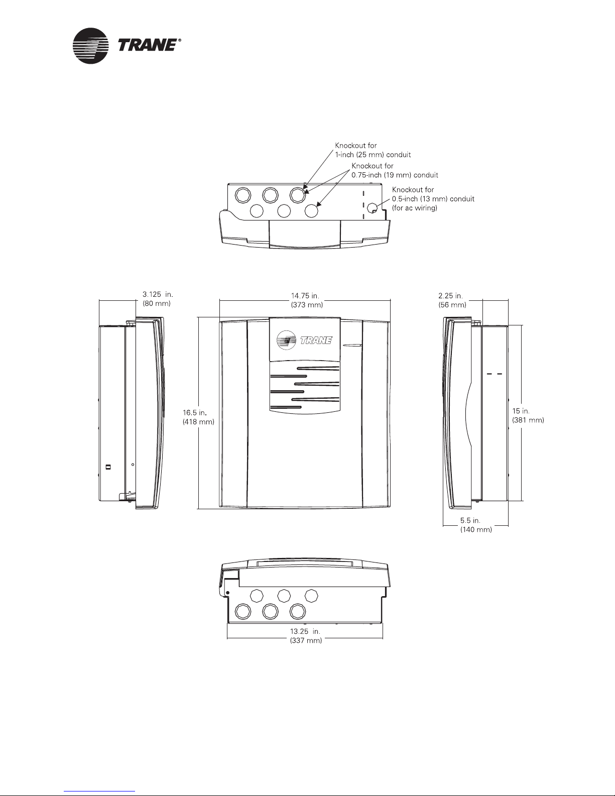
Figure 17. BMTX BCU enclosure dimensions
Top view
Mounting the hardware
Left view
Note: Six of the twelve knockouts are dual-
sized knockouts for 1-inch (25 mm) and
0.75-inch (19 mm) conduit.
BAS-APG001-EN 41
Front view
Right view
Bottom view
Page 54

Chapter 4 Installing the Tracer Summit BMTX BCU
Mounting the back of the enclosure
The back of the enclosure is shipped with the termination board installed
inside it.
IMPORTANT
The termination board should be shipped with the grounding screw
installed. Verify this by checking the location shown in
The enclosure door is shipped separately. If the door has already been
attached to the enclosure back, remove it.
To mount the back of the enclosure:
1. Using the enclosure back as a template, mark the location of the four
mounting holes on the mounting surface (see
Figure 18. Enclosure mounting holes
Figure 18.
Figure 18).
Termination board
grounding screw
(must be installed)
Mounting holes
42 BAS-APG001-EN
Page 55

Wiring high-voltage ac power
2. Set the enclosure back aside and drill holes for the screws at the
marked locations.
Drill holes for #10 (5 mm) screws or #10 wall anchors. Use wall
anchors if the mounting surface is dry wall or masonry.
3. Insert wall anchors if needed.
4. Secure the enclosure back to the mounting surface with the supplied
#10 (5 mm) screws.
Wiring high-voltage ac power
Verifying model number for local power requirements
Table 12 lists the available BMTX BCU model. You can find the model
number on the shipping label or on the product label inside the enclosure.
Table 12. BMTX BCU model number
Model Description
BMTX001DAB000 BMTX BCU, 120 Vac, UUKL listed
To ensure proper operation of the BMTX BCU, install the power supply
circuit in accordance with the following guidelines:
• The BCU must receive power from a dedicated power circuit. Failure
to comply may cause control malfunctions.
• A disconnect switch for the dedicated power circuit must be near the
controller, within easy reach of the operator, and marked as the dis
connecting device for the controller.
-
• High-voltage power-wire conduits or wire bundles must not contain
input/output wires. Failure to comply may cause the controller to mal
function due to electrical noise.
• High-voltage power wiring must comply with the National Electrical
Code (NEC) and applicable local electrical codes.
• High-voltage wiring requires three-wire 120/230 Vac service (line,
neutral, ground).
Note:
The transformer voltage utilization range is 120 Vac. T h e pane l
automatically detects whether the current is 50 or 60 cycle.
To connect high-voltage power wires:
WARNING
-
BAS-APG001-EN 43
Hazardous voltage!
Before making electrical connections, lock open the supply-power disconnect switch. Failure to do so may cause death or serious injury.
Page 56

Chapter 4 Installing the Tracer Summit BMTX BCU
CAUTION
Use copper conductors only!
Unit terminals are designed to accept copper conductors only. Other
conductors may cause equipment damage.
1. Lock open the supply-power disconnect switch.
2. At the top-right corner of the enclosure, remove the knockout for ½ in
(13
mm) conduit.
3. Open or remove the enclosure door if it has already installed.
4. Inside of the enclosure at the top-right corner, remove the high-voltage area cover plate.
5. Feed the high-voltage power wire into the enclosure.
6. Connect the line wire to the L terminal as shown in Figure 19 on page
45.
7. Connect the neutral wire to the N terminal.
8. Connect the green ground wire to the chassis ground screw. The
ground wire must be continuous back to the circuit breaker panel.
9. Replace the cover plate.
WARNING
Hazardous voltage!
The cover plate must be in place when the BCU is operating. Failure to
replace the cover plate could result in death or serious injury.
10. On a label, record the location of the circuit breaker panel and the
electrical circuit. Attach the label to the cover plate.
44 BAS-APG001-EN
Page 57
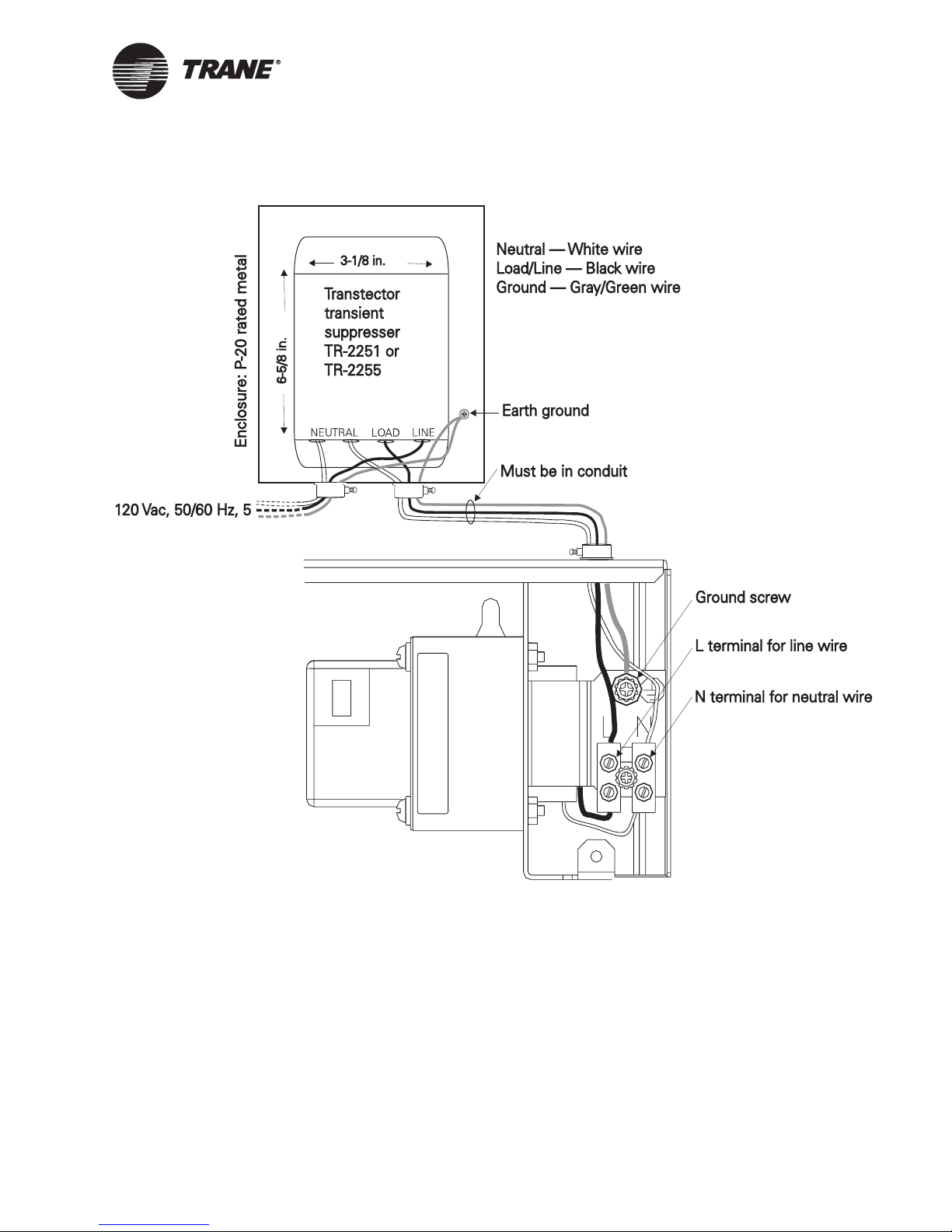
Figure 19. AC wiring
Wiring high-voltage ac power
BAS-APG001-EN 45
Page 58

Chapter 4 Installing the Tracer Summit BMTX BCU
EMI/RFI considerations
Take care to isolate HVAC controllers from electromagnetic interference
(EMI) and radio frequency interference (RFI). Such interference can be
caused by radio and TV towers, hospital diagnostic equipment, radar
equipment, electric power transmission equipment, and so on. In addi
tion, take care to prevent the BMTX BCU from radiating EMI and/or RFI.
The BMTX BCU is equipped with EMI/RFI filters that trap RFI to
ground. In most situations, a good earth ground will reduce EMI/RFI
problems by acting as a drain for EMI and RFI. If the BMTX BCU is
receiving or radiating interference, make sure that the earth ground is
good. Do not assume that the building conduit is an adequate ground.
Checking the earth ground
Though a proper earth ground is especially important in areas of high
EMI or RFI, always check the quality of the ground, regardless of
location.
WARNING
Hazardous voltage!
The cover plate must be in place when the BCU is operating. Failure to
replace the cover plate could result in death or serious injury.
If the earth ground has a voltage of more than 4 Vac, use a different
ground. Failure to do so could result in death or serious injury.
-
To check the quality of the earth ground:
1. Open the enclosure door.
2. Inside of the enclosure at the top-right corner, remove the high-voltage area cover plate.
3. Measure the ac voltage between the earth ground and the neutral terminal, as shown in Figure 20 on page 47.
Ideally, the voltage should be 0 Vac. Find a different ground if the
voltage exceeds 4 Vac. A higher voltage may result in:
• Danger to people touching the enclosure
• Erratic communications
• Erratic equipment operation (Because noise may affect voltage
levels at the inputs—the controller interprets input noise as
changes in temperature, humidity, pressure, and so on.)
4. Replace the cover plate.
46 BAS-APG001-EN
Page 59

Figure 20. Checking the earth ground
EMI/RFI considerations
BAS-APG001-EN 47
Page 60

Chapter 4 Installing the Tracer Summit BMTX BCU
Connecting the main circuit board
The main circuit board is attached to a plastic frame. It is shipped
separately. The board can be kept in the office and programmed while the
back of the enclosure is mounted and the termination board, which is
attached to the back of the enclosure, is wired. After programming has
been completed, connect the circuit board to the termination board as
shown in the following procedure.
To connect the circuit board:
1. Verify that the 24 Vac power cable is not connected to the termination
board.
2. Hold the circuit board frame at a 90° angle to the back of the
enclosure, as shown in
3. Connect the circuit board’s 60-pin ribbon cable to the termination
board’s 60-pin slot. The connector is keyed to the slot. To avoid
difficulty, make sure that the key is lined up with the slot.
Figure 21. Connecting the circuit board ribbon cable
Figure 21.
1. Align the snaps on the circuit board frame with the mounting locks at
2. Using the tabs that are at both ends of the top frame, push the two
48 BAS-APG001-EN
opposite ends of the enclosure back, as shown in
frames together. You will hear a click when the frames connect.
Figure 22 on page 49.
Page 61

Figure 22. Connecting the frames
Connecting the main circuit board
3. Connect the 24 Vac power cable to the termination board. The sevensegment LED display should light
up.
4. Connect the Ethernet cable to the Ethernet connector on the circuit
board (this step applies to UUKL nondedicated systems only).
BAS-APG001-EN 49
Page 62

Chapter 4 Installing the Tracer Summit BMTX BCU
Installing the door
To install the enclosure door:
1. Unpack the door and check for missing or damaged parts.
Check to make sure that the magnetic latches are installed. Check for
any cracks in the plastic.
2. Hold the door at a 90° angle from the enclosure back as shown in Figure 23.
3. Align the hinge pegs on the door with the hinge holes on the enclosure.
4. Gently lower the door until it rests securely in the hinge holes.
5. Verify that the door swings freely on the hinges and that the magnetic
latches hold the door securely when it is closed.
Figure 23. Installing the door
50 BAS-APG001-EN
Page 63

Transtector, Ethernet (UUKL nondedicated only), and LonTalk connections on the BMTX BCU
Transtector, Ethernet (UUKL
nondedicated only), and LonTalk
connections on the BMTX BCU
To comply with UUKL, a protection device must be wired to the BMTX
BCU to reduce transients in the ac power.
an ac power transient protection device to a BMTX BCU.
Figure 24. AC power transient protection wiring to the BMTX BCU
Figure 24 describes connecting
BAS-APG001-EN 51
Page 64

Chapter 4 Installing the Tracer Summit BMTX BCU
Figure 25 shows the Ethernet LAN connection (UUKL nondedicated only)
and the LonTalk connection to the BMTX BCU.
Figure 25. Ethernet (UUKL nondedicated only) and LonTalk connection
locations on the BMTX BCU
LonTalk connections
{
52 BAS-APG001-EN
Ethernet connection
Note:
A fully configured BCU draws a maximum of 25 VA from the
power transformer. No other devices may be powered from the
transformer.
Page 65

Chapter 5
Installing the Tracer MP581
programmable controller
Installation guidelines
Guidelines for installing a Tracer MP581 include:
• A Tracer MP581 that monitors the fire alarm control panel for
consistency (FACP) must be installed in the same room as the FACP.
It must be installed within 20 feet of the FACP. Cables between the
FACP and the Tracer MP581 must be in conduit.
• A Tracer MP581 that monitors and controls the fire smoke control
system (FSCS) must be installed in the same room as the FSCS. It
must be installed within 20 feet of the FSCS. Cables between the
FACP and Tracer MP581 must be in conduit.
▲IMPORTANT
Wiring between the Tracer MP581 and the FACP and between the Tracer
MP581 and the FSCS (point wiring) must be in conduit. The conduit
requirement is necessary, since the binary inputs to the Tracer MP581
are not supervised.
• Wiring from a Tracer MP581 to field sensors and relays is not
supervised. Installation of this wiring must conform to more stringent
requirements when a Tracer MP581 is part of a smoke control system
than when it is part of a standard mechanical system control.
BAS-APG001-EN 53
Page 66

Chapter 5 Installing the Tracer MP581 programmable controller
Specifications
The Tracer MP581 conforms to the specifications shown in Table 13.
Table 13. Tracer MP581 specifications
Weight 15 lb (7 kg)
Operating temperature From –40°F to 120°F (–40°C to 49°C)
Storage temperature From –58°F to 203°F (–50°C to 95°C)
Humidity 10–90% non-condensing
Altitude 6500 ft (2000 m)
Installation Category 3
Pollution Degree 2
High-voltage power requirements
Weight Mounting surface must be able to support
Analog to digital conversion
Digital to analog conversion
Microprocessor
Processor clock speed:
Memory RAM: 256 kB (16-bit word)
Clock Crystal controlled 32.768 kHz
Battery None required
North America: 120 Vac, 1 A maximum, 1
phase
25 lb (12 kg)
12 bit
12 bit
Motorola MC68332
20 MHz
EEPROM: 256 kB (8-bit word)
Flash: 1 MB (16-bit word)
54 BAS-APG001-EN
Page 67

Selecting a mounting location
Selecting a mounting location
Make sure that the location meets the operating environment requirements and clearance requirements described in the following sections.
The Tracer MP581 controller must be installed indoors. Trane recom
mends locating the Tracer MP581 controller in the same room (within 20
ft) of the controlled equipment to reduce wiring costs.
CAUTION
Equipment damage!
Install the Tracer MP581 in a location that is out of direct sunlight. Failure to do so may cause the Tracer MP581 to overheat.
Operating environment requirements
Make sure that the operating environment conforms to the specifications
listed in
Table 14. Operating environment specifications
Temperature From –40°F to 120°F (–40°C to 49°C)
Humidity 10–90% non-condensing
Altitude 6500 ft (2000 m)
High-voltage power
requirements
Weight Mounting surface must be able to support 25 lb (12 kg)
Table 14.
North America: 98–132 Vac, 1 A maximum, 1 phase
-
BAS-APG001-EN 55
Page 68

Chapter 5 Installing the Tracer MP581 programmable controller
Clearances and dimensions
Make sure that the mounting location has enough room to meet the minimum clearances shown in Figure 26. Figure 27 on page 57 shows the
dimensions of the Tracer MP581 enclosure.
Figure 26. Minimum clearances for enclosure
12 in. (30 cm)
24 in. (60 cm)
to fully open door
12 in. (30 cm)
12 in. (30 cm)
50 in. (130 cm) recommended
36 in. (90 cm)
56 BAS-APG001-EN
Page 69

Selecting a mounting location
Figure 27. Tracer MP581 enclosure dimensions
Top view
Left view
BAS-APG001-EN 57
Front view
Right view
Bottom view
Note:
Six of the twelve knockouts are dual-sized knockouts for 1-inch
(25 mm) and 0.75-inch (19 mm) conduit.
Page 70

Chapter 5 Installing the Tracer MP581 programmable controller
Mounting the back of the enclosure
The back of the enclosure is shipped with the termination board installed
inside it.
IMPORTANT
The termination board should be shipped with the grounding screw
installed. Verify this by checking the location shown in
The enclosure door is shipped separately. If the door has already been
attached to the enclosure back, remove it.
To mount the enclosure:
1. Using the enclosure as a template, mark the location of the four
mounting holes on the mounting surface (see
Figure 28. Enclosure mounting holes
Termination board
grounding screw
(must be installed)
Figure 28.
Figure 28).
Mounting hole
(four locations)
58 BAS-APG001-EN
Page 71

Wiring high-voltage ac power
2. Set the enclosure aside and drill holes for the screws at the marked
locations.
Drill holes for #10 (5 mm) screws or #10 wall anchors. Use wall
anchors if the mounting surface is dry wall or masonry.
3. Insert wall anchors if needed.
4. Secure the enclosure to the mounting surface with the supplied
#10 (5 mm) screws.
Wiring high-voltage ac power
Table 15 lists the available Tracer MP581 model. You can find the model
number on the shipping label or on the product label inside the enclosure.
Table 15. Tracer MP581 models
Model Number Description
BMTM000DAB00 Tracer MP581 controller, 120 Vac, UUKL
Circuit requirements
To ensure proper operation of the Tracer MP581, install the power supply
circuit in accordance with the following guidelines:
• The Tracer MP581 must receive high-voltage power from a dedicated
power circuit. Failure to comply may cause control malfunctions.
• A disconnect switch for the dedicated power circuit must be near the
controller, within easy reach of the operator, and marked as the dis
connecting device for the controller.
• High-voltage power-wire conduits or wire bundles must not contain
input/output wires. Failure to comply may cause the controller to mal
function due to electrical noise.
• High-voltage power wiring must comply with the National Electrical
Code (NEC) and applicable local electrical codes.
• High-voltage power wiring requires three-wire 120/230 Vac service.
Use copper conductors only.
Note:
The voltage utilization range for the Tracer MP581 transformer
is 120 Vac. The panel detects whether the current is 50 or 60
cycle.
-
-
BAS-APG001-EN 59
Page 72

Chapter 5 Installing the Tracer MP581 programmable controller
Wiring high-voltage power
WARNING
Hazardous voltage!
Before making electrical connections, lock open the supply-power disconnect switch. Failure to do so could result in death or serious injury.
CAUTION
Use copper conductors only!
Unit terminals are designed to accept copper conductors only. Other
conductors may cause equipment damage.
To connect high-voltage power wires:
1. Lock open the supply-power disconnect switch.
2. At the top right corner of the enclosure, remove the knockout and
install 0.5-inch (13 mm) conduit (see
Figure 29. Knockout for high-voltage power wires
Figure 29).
Power wire entry through
knockout for 0.5-inch conduit
3. Open or remove the Tracer MP581 door if it is already installed.
4. Inside of the enclosure at the top-right corner, remove the high-voltage area cover plate.
5. Feed the high-voltage power wires into the enclosure.
6. Connect the line wire to the L terminal as shown in Figure 30 on page
61.
7. Connect the neutral wire to the N terminal.
8. Connect the green ground wire to the chassis ground screw. The
ground wire must be continuous back to the circuit-breaker panel.
9. Replace the cover plate.
60 BAS-APG001-EN
Page 73
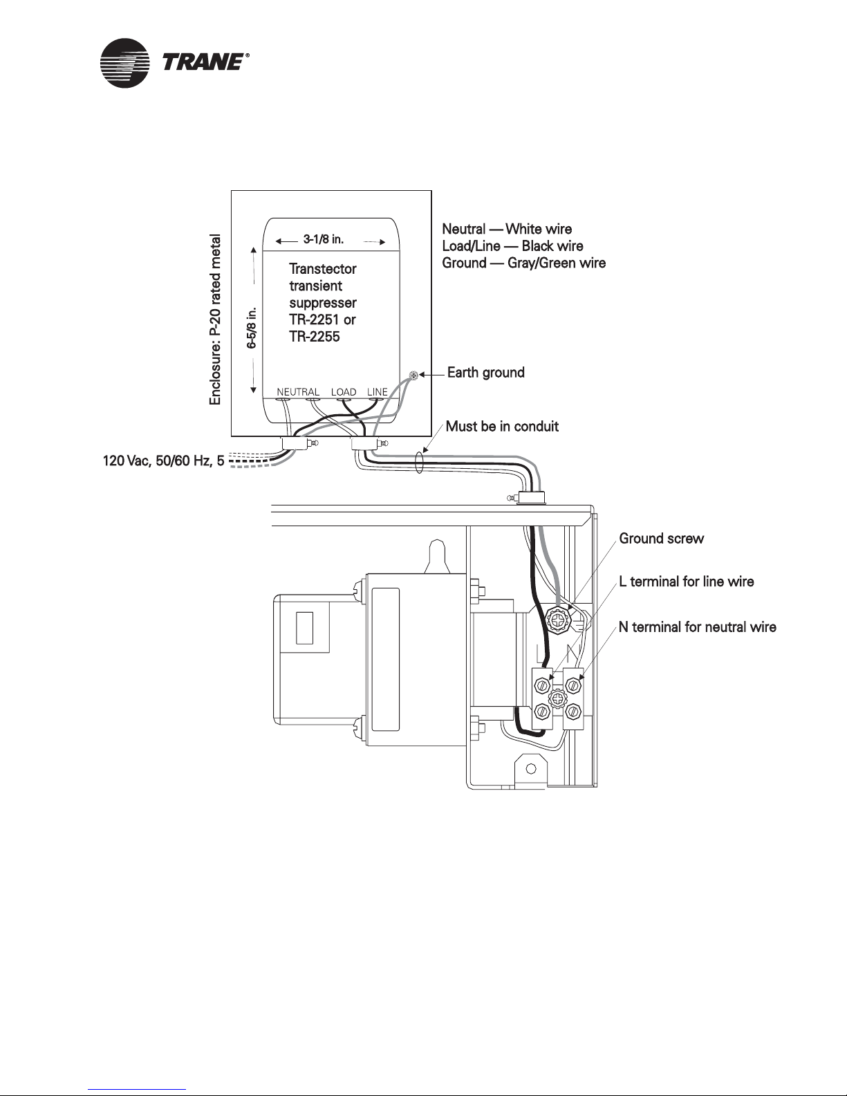
Wiring high-voltage ac power
Figure 30. Terminal block for high-voltage power wires
BAS-APG001-EN 61
WARNING
Hazardous voltage!
The cover plate must be in place when the controller is operating. Failure to replace the cover plate could result in death or serious injury.
10. On a label, record the location of the circuit-breaker panel and the
electrical circuit. Attach the label to the cover plate.
Page 74

Chapter 5 Installing the Tracer MP581 programmable controller
EMI/RFI considerations
Take care to isolate HVAC controllers from electromagnetic interference
(EMI) and radio frequency interference (RFI). Such interference can be
caused by radio and TV towers, hospital diagnostic equipment, radar
equipment, electric power transmission equipment, and so on. In addi
tion, take care to prevent the Tracer MP581 controller from radiating
EMI and/or RFI.
The Tracer MP581 is equipped with EMI/RFI filters that trap RFI to
ground. In most situations, a good earth ground will reduce EMI/RFI
problems by acting as a drain for EMI and RFI. If the Tracer MP581 is
receiving or radiating interference, make sure that the earth ground is
good. Do not assume that the building conduit is an adequate ground.
Checking the earth ground
Though a proper earth ground is especially important in areas of high
EMI or RFI, always check the quality of the ground, regardless of
location.
WARNING
-
Hazardous voltage!
The cover plate must be in place when the controller is operating. Failure to replace the cover plate could result in death or serious injury.
If the earth ground has a voltage of more than 4 Vac, use a different
ground. Failure to do so could result in death or serious injury.
To check the quality of the earth ground:
1. Open the enclosure door.
2. Inside of the enclosure at the top-right corner, remove the high-voltage area cover plate.
3. Measure the ac voltage between the earth ground and the neutral terminal, as shown in Figure 31 on page 63.
Ideally, the voltage should be 0 Vac. Find a different ground if the
voltage exceeds 4 Vac. A higher voltage may result in:
• Danger to people touching the enclosure
• Erratic communications
• Erratic equipment operation (Because noise may affect voltage
levels at the inputs—the controller interprets input noise as
changes in temperature, humidity, pressure, and so on.)
4. Replace the cover plate.
62 BAS-APG001-EN
Page 75

Figure 31. Checking the earth ground
EMI/RFI considerations
BAS-APG001-EN 63
Page 76

Chapter 5 Installing the Tracer MP581 programmable controller
Wiring inputs and outputs
The Tracer MP581 enclosure is designed to simplify the wiring and configuration of inputs and outputs by providing a large space for routing
wires and by eliminating the need to manipulate jumpers.
Tracer MP581 inputs and outputs.
Table 16. Inputs and outputs
Ty p e Number Description
Universal inputs 12 Dry-contact binary, thermistor,
Static pressure
input
Binary outputs 6 Powered relay contacts, 6 VA at 24 Vac
Analog outputs 6 0–10 Vdc or 0–20 mA
1 Differential pressure sensor, 5 Vdc,
Table 16 lists
0–20 mA, 0–10 Vdc, linear resistance.
The first four inputs can be used
directly with resistance temperature
detectors (RTDs).
0–5 in. wc
Input/output wiring guidelines
Input/output wiring must meet the following guidelines:
• Wiring must conform with the National Electrical Code and local elec-
trical codes.
• Use only 18 AWG twisted-pair wire with stranded, tinned-copper con-
ductors.
• Binary input/output wires must not exceed 1,000 ft (300 m).
• Analog input wires must not exceed 300 ft (100 m) for thermistors
and 0–10 Vdc inputs and 1,000 ft (300 m) for 0–20 mA inputs.
• Analog output wires must not exceed 1,000 ft (300 m) for 0–10 Vdc
outputs and 0–20 mA outputs.
• Do not run input/output wires in the same wire bundle with high-
voltage power wires. Running input/output wires with 24 Vac power
wires is acceptable, but the input wire must be shielded.
• Terminate input/output wires before installing the main circuit board
(see
“Installing the circuit board” on page 76).
64 BAS-APG001-EN
Page 77

Wire routing
Figure 32 shows how to route input/output wires through the enclosure.
It also shows the locations of wire-tie brackets. See Figure 27 on page 57
for knockout locations and dimensions. Metal conduit may be required by
local codes when running input/output wires.
Figure 32. Wire routing
Brackets for wire
ties (9 locations)
Wiring inputs and outputs
BAS-APG001-EN 65
Recommended
communication wire route
Providing low-voltage power for inputs and outputs
The Tracer MP581 controller can provide low-voltage power to inputs and
outputs.
terminals on the termination board. The following limitations apply:
• Four 24 Vdc screw terminals supply a total of up to 250 mA of power.
• Two 24 Vac screw terminals supply a total of up to 17 VA of power.
Note that more than one input or output can receive power from a given
screw terminal. The only limitation is the total amount of power supplied.
Figure 33 on page 66 shows the location of the low-voltage screw
The 50
terminals and binary outputs.
VA of available power supplies both the 24 Vac screw
Page 78

Chapter 5 Installing the Tracer MP581 programmable controller
Screw terminal locations
Figure 33 shows screw terminal locations on the termination board. The
top row of screw terminals is for signal wires, and the bottom row of screw
terminals is for common wires. To make sure that the wires lie flat, use
the wire strip guide on the termination board to strip input/output wires
to the correct length.
Figure 33. Screw-terminal locations
Common terminals
Signal terminals
24 Vac power
connector
Binary outputs
24 Vac power
Analog outputs
Wire strip guide
Universal inputs
(IN1–IN4 can
accept RTDs)
inputs
24 Vdc power
LonTalk screw terminals
LonTalk jack for Rover service tool
I/O bus for EX2 expansion modules
66 BAS-APG001-EN
Duct-static pressure connector
Page 79

Wiring inputs and outputs
Wiring universal inputs
The Tracer MP581 controller has 12 universal inputs. Use the Rover service tool to configure inputs for analog or binary operation.
The common terminals on the Tracer MP581 termination board are connected to the metal enclosure by means of a ground screw. Shield wires
should be connected to a common terminal.
Tracer MP581 places on sensors.
Ta b l e 17. Load placed on sensors
Input type Load on sensor
Vdc (linear) 21 kΩ
mA (linear) 221 Ω
Wiring binary inputs
Use binary inputs to monitor statuses, such as fan on/off and alarm
resets.
To wire a binary input:
1. Connect the common wire to a common terminal as shown in
Figure 34.
Table 17 shows the load the
Binary switch
Signal
Common
Note that, because the common terminals are in parallel, you can
wire the common wire to any available common terminal.
2. Connect the shield wire to a common terminal at the termination
board and tape it back at the input device.
3. Connect the signal wire to an available input terminal (IN1–IN12).
4. Use the Rover service tool to configure the input for binary operation.
Figure 34. Wiring a binary input
< 1000 ft
(300 m)
Tape back shield
Shield
NOTE: To reduce the potential for transients, locate input
devices in the same room with the Tracer MP581.
BAS-APG001-EN 67
Page 80

Chapter 5 Installing the Tracer MP581 programmable controller
Wiring analog outputs
The Tracer MP581 controller has six analog outputs. These outputs can
be either 0–10 Vdc outputs or 0–20
actuators and secondary controllers.
To wire an analog output:
1. For three-wire applications, use a 3-conductor cable with a shield. For
two-wire applications, use a 2-conductor cable with a shield. Connect
the shield to a common terminal at the termination board and tape it
back at the output device (see
as the common connection.
2. Connect the signal wire to an available analog output terminal
(AO1–AO6).
3. Connect the supply wire to a 24 Vac terminal as required.
4. Use the Rover service tool to configure the analog output.
Figure 35. Wiring analog outputs
Ac powered actuator
24 Vac
mA outputs. Analog outputs control
Figure 35). Do not use the shield wire
Signal
Common
Signal
Common
0–10 Vdc output
Load > 500 Ω
Signal
Common
0–20 mA output
Load < 500 Ω
< 1000 ft
(300 m)
< 1000 ft
(300 m)
< 300 ft
(100 m)
Tape back shield
NOTE: To reduce the potential for transients, locate output
devices in the same room with the Tracer MP581.
68 BAS-APG001-EN
Page 81

Wiring inputs and outputs
Wiring binary outputs
The Tracer MP581 controller has six binary outputs. These are powered
outputs, not dry-contact outputs.
IMPORTANT
Use pilot relays for dry-contact outputs when the load is greater than
6
VA or has a current draw of greater than 0.25 A. Use powered outputs
when the load is less than 6
0.25
A.
Note:
When controlling coil-based loads, such as pilot relays, do not
forget to account for “inrush” current. Inrush current can be
three (or more) times greater than the operating current. You
can find information on inrush current for specific types of out
puts in their product specifications.
To wire a binary output:
1. Connect the common wire to a common terminal as shown in
Figure 36.
2. Connect the shield wire to a common terminal at the termination
board and tape it back at the output device.
3. Connect the signal wire to an available binary output terminal
(BO1–BO6).
VA or has a current draw of less than
-
4. Use the Rover service tool to configure the binary output.
BAS-APG001-EN 69
Page 82
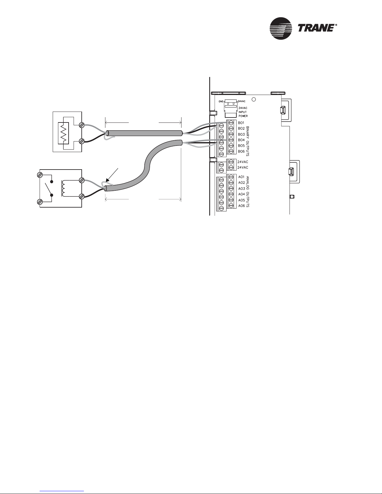
Chapter 5 Installing the Tracer MP581 programmable controller
Figure 36. Wiring binary outputs
Powered output
Signal
Common
Pilot relay
24 Vac coil
NOTE: To reduce the potential for transients, locate output
devices in the same room with the Tracer MP581.
Tape back shield
Signal
Common
< 1000 ft
(300 m)
< 1000 ft
(300 m)
Checking binary inputs
To check binary inputs for proper operation:
1. Make sure that the sensor is connected and closed.
2. Set the multi-meter to measure Vac, then measure the voltage across
the input connections at the signal and common screw terminals.
The measured voltage should be less than 0.1 Vac. If the voltage is
greater than this, the input readings may change erratically.
3. Set the multi-meter to measure Vdc, then measure the voltage across
the input at the signal and common screw terminals.
The measured voltage should be less than 0.1 Vdc. If the voltage is
greater than this, the input readings may be offset.
CAUTION
Equipment damage!
Continue to step 4 only if you completed steps 2 and 3 successfully.
Measuring resistance may damage the meter if the voltage is too high.
4. Set the multi-meter to measure resistance. If you completed steps 2
and 3 successfully, measure the resistance across the input.
The resistance should be less than 200 Ω when the binary input is
closed and greater than 1 kΩ when it is open.
70 BAS-APG001-EN
Page 83

Checking outputs
Checking outputs
Follow the procedures in this section to test outputs for proper operation.
IMPORTANT
Perform the tests in this section before providing power to the termination board or installing the main circuit board. Failure to do so will
result in incorrect multi-meter readings.
To test outputs for proper operation, you need the following tools:
• Digital multi-meter
• Small flat-tip screwdriver
Checking binary outputs
To check binary outputs for proper operation:
1. Set the multi-meter to measure Vac, then measure the voltage across
the binary output at the common and signal screw terminals.
The measured voltage should be less than 0.1 Vac. If the voltage is
greater than this, the load may turn on and off unexpectedly. Check
for the following problems:
• A shared power supply may be incorrectly connected. Check the
wire to make sure that no additional connections have been made.
• The wire may have an induced voltage somewhere along its
length.
2. Set the multi-meter to measure Vdc, then measure the voltage across
the binary output at the common and signal screw terminals.
The measured voltage should be less than 0.1 Vdc. If the it is greater
than this, a shared power supply may be incorrectly connected. Check
the wire to make sure that no additional connections have been made.
CAUTION
Equipment damage!
Continue to step 3 only if you completed steps 1 and 2 successfully.
Measuring resistance may damage the meter if the voltage is too high.
3. Set the multi-meter to measure resistance. If you completed steps 1
and 2 successfully, measure the resistance across the binary output to
confirm that there are no shorts and no open circuits.
Resistance is load dependent. Pilot relays have a relatively low resistance of less than 1 kΩ, but some actuators have a high resistance.
Check to see what kind of binary output is connected before checking
for open and short circuits.
BAS-APG001-EN 71
Checking 0–10 Vdc analog outputs
To check 0–10 Vdc analog outputs for proper operation:
Page 84

Chapter 5 Installing the Tracer MP581 programmable controller
1. Make sure that the actuator is connected but powered off.
2. Set the multi-meter to measure Vac, then measure the voltage across
the analog output at the signal and common screw terminals.
The measured voltage should be less than 0.1 Vac. If the voltage is
greater than this, the load may turn on and off unexpectedly. Check
for the following problems:
• A shared power supply may be incorrectly connected. Check along
the wire to make sure that no additional connections have been
made.
• The wire may have an induced voltage somewhere along its
length.
3. Set the multi-meter to measure Vdc, then measure the voltage across
the analog output at the signal and common screw terminals.
The measured voltage should be less than 0.1 Vdc. If the voltage is
greater than this, a shared power supply may be incorrectly con
nected. Check along the wire to make sure that no additional connections have been made.
CAUTION
-
Equipment damage!
Continue to step 4 only if you completed steps 2 and 3 successfully.
Measuring resistance may damage the meter if the voltage is too high.
4. Set the multi-meter to measure resistance. If you completed steps 2
and 3 successfully, measure the resistance across the analog output at
the signal and common screw terminals.
The resistance should be greater than 500 Ω. (The analog output will
not be able to reach 10 Vdc if the load resistance is less than 500 Ω
.)
Checking 0–20 mA analog outputs
To check 0–20 mA analog outputs for proper operation:
1. Make sure that the actuator is connected but powered off.
2. Set the multi-meter to measure Vac, then measure the voltage across
the analog output at the signal and common screw terminals.
The measured voltage should be less than 0.1 Vac. If the voltage is
greater than this, the load may turn on and off unexpectedly. Check
for the following problems:
• A shared power supply may be incorrectly connected. Check along
the wire to make sure that no additional connections have been
made.
• The wire may have an induced voltage somewhere along its
length.
72 BAS-APG001-EN
Page 85

Checking outputs
3. Set the multi-meter to measure Vdc, then measure the voltage across
the analog output at the signal and common screw terminals.
The measured voltage should be less than 0.1 Vdc. If the voltage is
greater than this, a shared power supply may be incorrectly con
nected. Check along the wire to make sure that no additional connections have been made.
BAS-APG001-EN 73
Page 86

Chapter 5 Installing the Tracer MP581 programmable controller
Wiring LonTalk to the Tracer MP581
IMPORTANT
When installing the Tracer MP581 controller in areas of high electromagnetic interference (EMI) and radio frequency interference (RFI), follow the additional installation instructions in “EMI/RFI considerations”
on page 62.
Note:
Although LonTalk links are not polarity sensitive, we recommend that you keep polarity consistent throughout the site.
To wire the LonTalk link:
1. At the first Tracer MP581 on the link, complete the following steps:
• Connect the white wire to the first (or third) LonTalk screw termi-
nal as shown in Figure 37.
• Connect the black wire to the second (or fourth) LonTalk screw
terminal.
• If this is the first LonTalk controller on the daisy chain, place a
105
Ω termination resistor across the LonTalk screw terminals.
Figure 37. Wiring the first device to the LonTalk connection on the
termination board
Note: Place a 105 Ω termination
resistor at the first and last LonTalk
device on the daisy chain. Termination
resistors require insulation, such as
heat shrink tubing, to avoid accidental
shorts to other conductors.
2. At the next Tracer MP581 (or other LonTalk controller) on the link:
• Connect the white wires to the first and third LonTalk screw ter-
minals (as shown in Figure 38 on page 75).
• Connect the black wires to the second and fourth LonTalk screw
terminals.
74 BAS-APG001-EN
Page 87
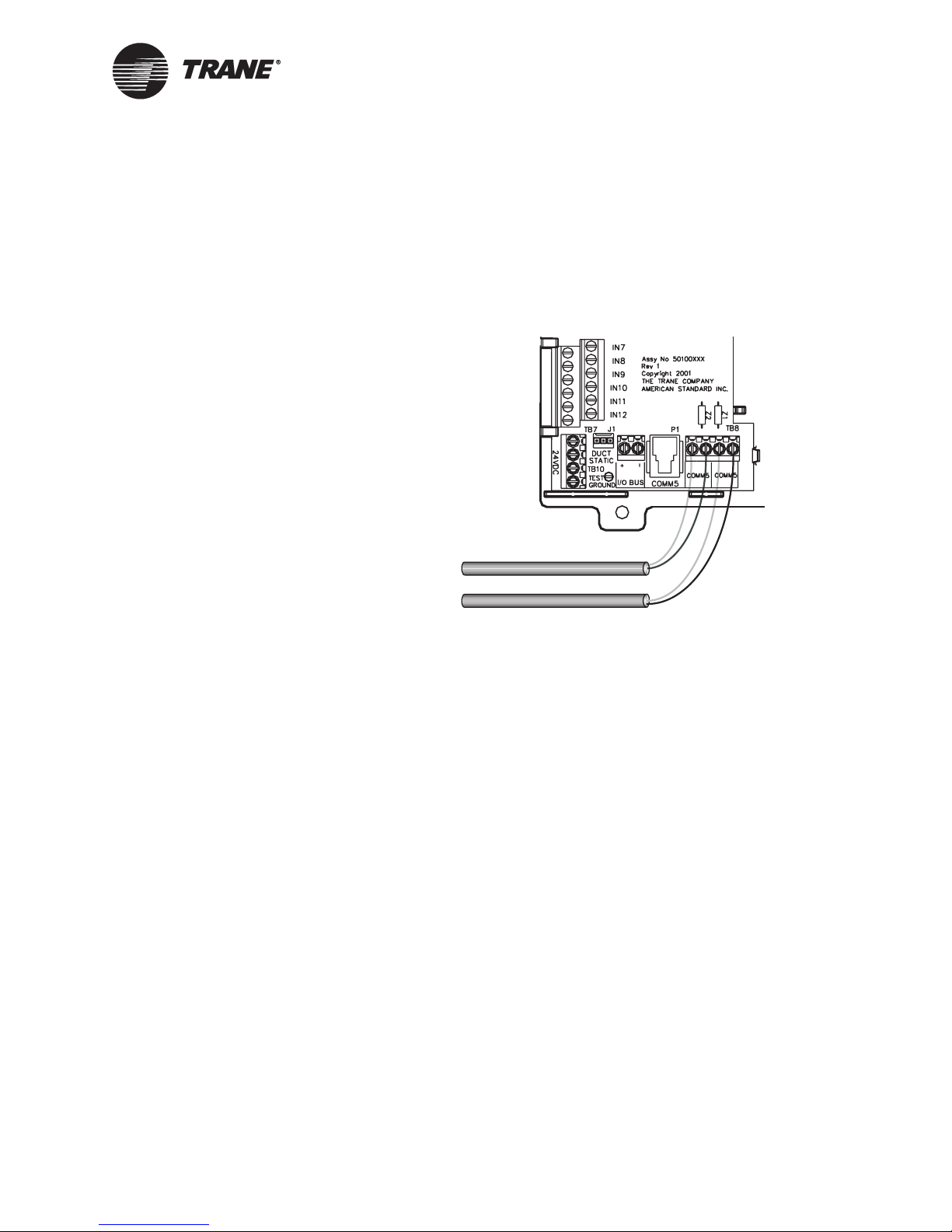
Wiring LonTalk to the Tracer MP581
3. At the last controller on the LonTalk link:
• Connect the white wire to the first LonTalk screw terminal.
• Connect the black wire to the second LonTalk screw terminal.
• Place a 105 Ω termination resistor across the LonTalk screw
terminals.
Figure 38. Wiring the next device to the LonTalk connection on the
termination board
BAS-APG001-EN 75
Page 88
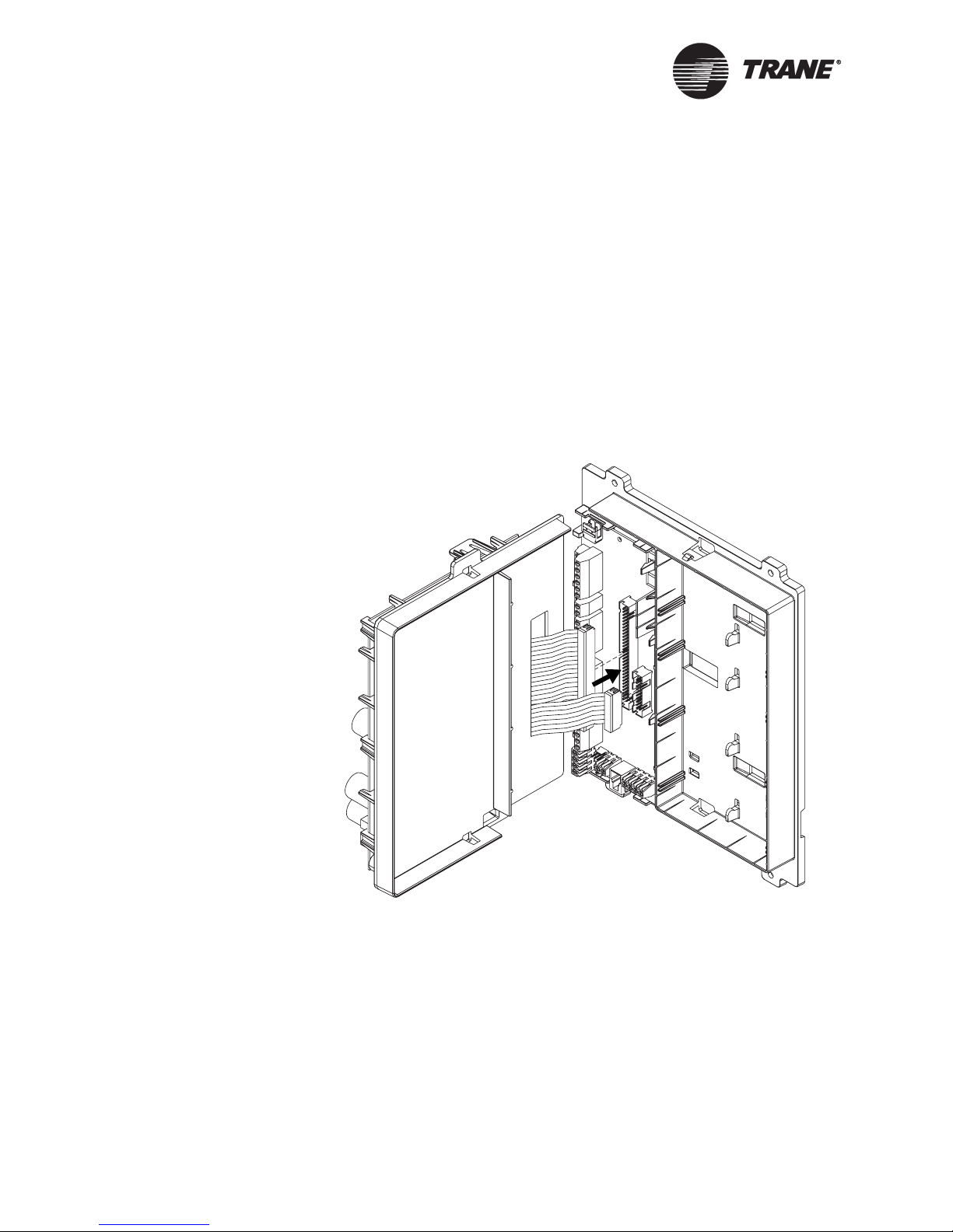
Chapter 5 Installing the Tracer MP581 programmable controller
Installing the circuit board
The main circuit board is not installed in the Tracer MP581 enclosure
when it ships. You can store the circuit board in the office while the enclo
sure is mounted and wired. After wiring has been completed, connect the
circuit board to the termination board.
To install the circuit board:
1. Open the enclosure door.
2. Verify that the 24 Vac power cable is not connected to the termination
board (see
3. Hold the top plastic frame, which holds the circuit board, at a 90°
angle to the bottom frame as shown in
Figure 39. Connecting the cables
Figure 41 on page 78).
-
Figure 39.
4. Connect the 60-pin cable to the 60-pin slot, then connect the 20-pin
76 BAS-APG001-EN
cable to the 20-pin slot.
The connectors fit only one way. If you have difficulty connecting
them, make sure that the plastic grooves line up with the slots.
Page 89

Installing the circuit board
5. Align the snaps on the top frame with the mounting locks on the bottom frame, as shown in Figure 40, then push the two frames together.
You will hear a click when the frames connect.
Figure 40. Connecting the frames
BAS-APG001-EN 77
6. Locate the 24 Vac power connector on the termination board (see
Figure 41 on page 78). Remove the mating plug with screw terminals.
7. Attach the 24 Vac power-supply cable to the screw terminals on the
mating plug.
8. Connect the mating plug to the 24 Vac power connector on the termination board. The green status LED should light up.
9. Check status LEDs according to the information given in “Interpreting LEDs” on page 79.
Page 90

Chapter 5 Installing the Tracer MP581 programmable controller
Figure 41. 24 Vac power-supply cable connection
24 Vac power connector
78 BAS-APG001-EN
Page 91

Verifying operation and communication of the Tracer MP581
Verifying operation and communication
of the Tracer MP581
This chapter describes the location and function of the Service Pin button
and the light-emitting diodes (LEDs) on the Tracer MP581 controller.
Service Pin button
The Service Pin button is located on the main circuit board as shown in
Figure 42. Use the Service Pin button in conjunction with a service tool or
BAS to:
• Identify a device
• Add a device to the active group
• Verify PCMCIA communications
• Make the green Status LED “wink” to verify that the controller is
communicating on the link
Refer to the Rover Operation and Programming guide,
EMTX-SVX01D-EN, for information on how to use the Service Pin button.
Interpreting LEDs
The information in this section will help you interpret LED activity. The
location of each LED is shown in
Figure 42. Service Pin button and LED locations
Figure 42.
BO1–BO6 LEDs (green)
Service LED (red)
Service Pin button
Comm LED (yellow)
Status LED (green)
BAS-APG001-EN 79
Page 92

Chapter 5 Installing the Tracer MP581 programmable controller
Binary output LEDs
The BO1–BO6 LEDs indicate the status of the six binary outputs.
Table 18 describes binary output LED activity.
Note:
Each binary output LED reflects the status of the output relay on the
circuit board. It may or may not reflect the status of the equipment
the binary output is controlling. Field wiring determines whether the
state of the binary output LED also applies to the status of the end
device.
Table 18 describes the LED states.
Ta b l e 18 . Binary output LEDs
LED activity Explanation
LED is on continuously The relay output is energized.
LED is off continuously The relay output is de-energized or there is no
Service LED
The red Service LED indicates whether the controller is operating normally. Table 19 describes Service LED activity.
power to the board.
Ta b l e 19 . Red Service LED
LED activity Explanation
LED is off continuously
when power is applied to
the controller
LED is on continuously
when power is applied to
the controller
LED flashes once every
second
1
Restore the controller to normal operation using the Rover service tool. Refer to
EMTX-SVX01D-EN for more information.
The controller is operating normally.
The controller is not working properly, or
someone is pressing the Service Pin button.
The controller is not executing the application
software because the network connections
and addressing have been removed.
1
80 BAS-APG001-EN
Page 93

Verifying operation and communication of the Tracer MP581
Status LED
The green Status LED indicates whether the controller has power applied
to it.
Table 20 describes Status LED activity.
Table 20. Green Status LED
LED activity Explanation
LED is on continuously Power is on (normal operation).
LED blinks (¼ second on,
¼ second off for 10 seconds)
LED blinks rapidly Flash download is being received.
LED is off continuously Either the power is off or the controller has
1
By sending a request from the Rover service tool, you can request the controller’s
green LED to blink (“wink”), a notification that the controller received the signal and
is communicating.
The auto-wink option is activated, and the
controller is communicating.
malfunctioned.
1
Comm LED
The yellow Comm LED indicates the communication status of the Tracer
MP581 controller.
Table 21 describes Comm LED activity.
Table 21. Yellow Comm LED
LED activity Explanation
LED is off continuously The controller is not detecting any communica-
tion (normal for stand-alone applications).
LED blinks The controller detects communication (normal
for communicating applications, including data
sharing).
LED is on continuously The LED may flash so fast that it looks as if it is
on continuously. If this LED activity occurs at any
time other than discovery, it indicates an abnor
mal condition. For example, the site may have
excessive radio frequency interference (RFI).
-
BAS-APG001-EN 81
Page 94

Chapter 5 Installing the Tracer MP581 programmable controller
Installing the door
To install the enclosure door:
1. Unpack the door and check for missing or damaged parts.
Check to make sure that the magnetic latches and touch screen (if
ordered) are installed. Check for any cracks in the plastic.
2. Hold the door at a 90° angle from the enclosure as shown in Figure 43
on page 82.
Figure 43. Aligning the enclosure door
3. Align the hinge pegs on the door with the hinge holes on the
4. Gently lower the door until it rests securely in the hinge holes.
5. Verify that the door swings freely on the hinges and that the magnetic
Removing the door
Remove the door to simplify wiring or when upgrading the controller with
a door-mounted operator display.
To remove the enclosure door:
1. Open the door to a 90° angle from the enclosure.
82 BAS-APG001-EN
enclosure.
latches hold the door securely when it is closed.
Page 95

Installing the door
2. For doors with an operator display, disconnect the operator-display
cable from operator display.
3. Lift the door to pull the hinges from the hinge holes.
BAS-APG001-EN 83
Page 96

Chapter 5 Installing the Tracer MP581 programmable controller
84 BAS-APG001-EN
Page 97

Chapter 6
Installing the EX2 expansion
module
The EX2 is a field-installed expansion module for the Tracer MP581 programmable controller. Up to four EX2s with metal enclosure, model number 4950 0523, can be connected to a Tracer MP581. Each EX2 adds the
following inputs and outputs to a Tracer MP581:
• Six universal inputs
• Four binary outputs
• Four analog outputs
The enclosure package includes:
• EX2 circuit board fastened to the back piece of a metal enclosure
• Removable metal cover
Make sure that the operating environment conforms to the specifications
listed in
on page 86.
Table 22. Dimensions and clearances are illustrated in Figure 44
Table 22. Operating environment specifications
Temperature From –40°F to 120°F (–40°C to 49°C)
Humidity 5–93%, non-condensing
Power 24 Vac, 50/60 Hz, 10 VA main board and 6 VA max per
binary output
Mounting Weight
(frame-mount)
Mounting Weight
(metal enclosure)
Altitude 6,500 ft (2,000 m)
Installation Category 3
Pollution Degree 2
Mounting surface must be able to support 2 lb (1 kg)
Mounting surface must be able to support 8 lb (4 kg)
BAS-APG001-EN 85
Page 98

Chapter 6 Installing the EX2 expansion module
Figure 44. Dimensions and clearances for metal-enclosure EX2
1 in.
(25 mm)
9 in.
(229 mm)
2 in.
(51 mm)
(178 mm)
2 in.
(51 mm)
7 in.
1.875 in.
(48 mm)
6.5 in.
(165 mm)
0.28 in.
(7 mm)
9 in.
(229 mm)
24 in.
(610 mm)
10. 37 in .
(263 mm)
width with
cover
Clearances
Dimensions
1 in.
(25 mm)
1 in.
(25 mm)
10. 25 in .
2.25 in.
(58 mm)
(260 mm)
width without cover
Storage environment
The storage environment must meet the following requirements:
• Temperature: From –40°F to 185°F (–40°C to 85°C)
• Relative humidity: 5–93%, non-condensing
Mounting location
Trane recommends locating the EX2 module:
• In an environment protected from the elements
• Where public access is restricted to minimize the possibility of tam-
pering or vandalism
• Near the controlled equipment to reduce wiring costs
• Where it is easily accessible for service personnel
• In conduit, in the same room, and no more than 20 ft (6.1 m) from the
FACP
86 BAS-APG001-EN
Page 99

Terminal strips
Te rm i n a l s t r i p s
The EX2 module is shipped with terminal strips already in place
(
Figure 45). If you need to replace the circuit board, you can transfer the
terminal strips to the new board without rewiring.
Figure 45. Terminal strip locations
Binary outputs
Universal inputs
terminal strip
terminal strip
Analog outputs
terminal strip
Mounting the metal-enclosure module
To mount the enclosure:
1. Unscrew the two screws on the front of the enclosure and remove the
cover.
2. Using the enclosure as a template, mark the location of the four
mounting holes on the mounting surface (
3. Set the enclosure aside and drill holes for the screws at the marked
locations.
4. Drill holes for #10 (5 mm) screws or #10 wall anchors. Use wall
anchors if the mounting surface is dry wall or masonry.
5. Insert wall anchors if needed.
6. Secure the enclosure to the mounting surface with #10 (5 mm) screws
(not included).
Figure 46 on page 88).
BAS-APG001-EN 87
Page 100

Chapter 6 Installing the EX2 expansion module
Figure 46. Mounting the metal-enclosure EX2
AC-power wiring
Use 16 AWG copper wire for ac-power wiring. All wiring must comply
with National Electrical Code and local codes. Use a UL-listed Class 2
power transformer supplying a nominal 24 Vac. The transformer must be
sized to provide adequate power to the EX2 module (10
(a maximum of 6 VA per binary output).
Please read the warnings and cautions before proceeding.
WARNING
Hazardous voltage!
Before making line voltage electrical connections, lock open the supplypower disconnect switch. Failure to do so could result in death or seri
ous injury.
WARNING
Hazardous voltage!
Make sure that the 24 Vac transformer is properly grounded. Failure to
do so could result in death or serious injury.
VA) a nd o utpu ts
-
88 BAS-APG001-EN
 Loading...