

Trane CLCH-SVX02C-EN, Energy Wheels Installation Operation & Maintenance

Installation
Operation
Maintenance
Energy Wheels
for M-Series Climate Changer™ Air
Handlers
February 2004 CLCH-SVX02C-EN

General
Information
Use this manual to install, startup, operate, and maintain the energy wheel
module for M-Series Climate Changer™ air handlers. Carefully review the
procedures discussed in this manual to minimize installation and startup
difficulties. The startup and adjustment procedures discussed in this manual
should be done by qualified, experienced HVAC technicians.
Your personal safety and the proper operation of this machine depend upon
the strict observance of these precautions.
Warnings and Cautions
NOTICE: Warnings and Cautions appear at appropriate sections
throughout this literature. Read these carefully.
WARNING: Indicates a potentially hazardous situation which, if not
avoided, could result in death or serious injury.
CAUTION: Indicates a potentially hazardous situation which, if not
avoided, may result in minor or moderate injury. It may also be used to
alert against unsafe practices.
CAUTION: Indicates a situation that may result in equipment or property-damage only accidents.
© 2004 American Standard Inc. All rights reserved CLCH-SVX02C-EN

Contents
Introduction
General Information .......................................................2
Description
How the Modules Arrive at the Job Site....................... 4
Receiving Inspection.......................................................5
Storage ............................................................................ 5
Contractors’ Responsibilities ......................................... 5
Installation
Service Clearance ...........................................................6
Rigging/Lifting.................................................................6
Assembly.........................................................................7
Actuator Installation ....................................................... 7
Module-to-Module Assembly ........................................8
Wiring
Energy Wheel Motor....................................................... 9
Options ............................................................................ 9
Operation
Energy Wheel Startup .................................................. 10
Routine Maintenance
Cleaning the Energy Wheel.......................................... 11
Segment Removal/Replacement ................................. 11
Cleaning the Energy Wheel Motor .............................. 14
Cleaning the Module .................................................... 15
Bearing and Motor Lubrication.................................... 15
Energy Wheel Drive Belt Adjustment.......................... 15
Air Filters ....................................................................... 15
Service and Repair
Bearing/Drive Belt Replacement.................................. 16
Seal Adjustment............................................................17
Drive Motor and Pulley Replacement .........................18
Troubleshooting
Probable Causes/Actions..............................................19
CLCH-SVX02C-EN 3
Description
The M-Series Climate Changer™ air
handler energy wheel module is an
efficient, low-maintenance energy
recovery device. It is an integral part
of an entire air-handling system. The
module consists of the energy wheel
cassette assembly and access on
either side of the energy wheel.
All energy wheel modules feature
removable individual segments for
cleaning and replacement.
M-Series air handlers sizes 3 to 8 are
designed for the energy wheel
cassette to slide out of the module
for changing bearings, motors, and
belts. A removable panel is provided
on both sides for this purpose (see
Figure 1).
Figure 1. M-Series air handler
energy wheel module with
removable access panel, size 3 to 8
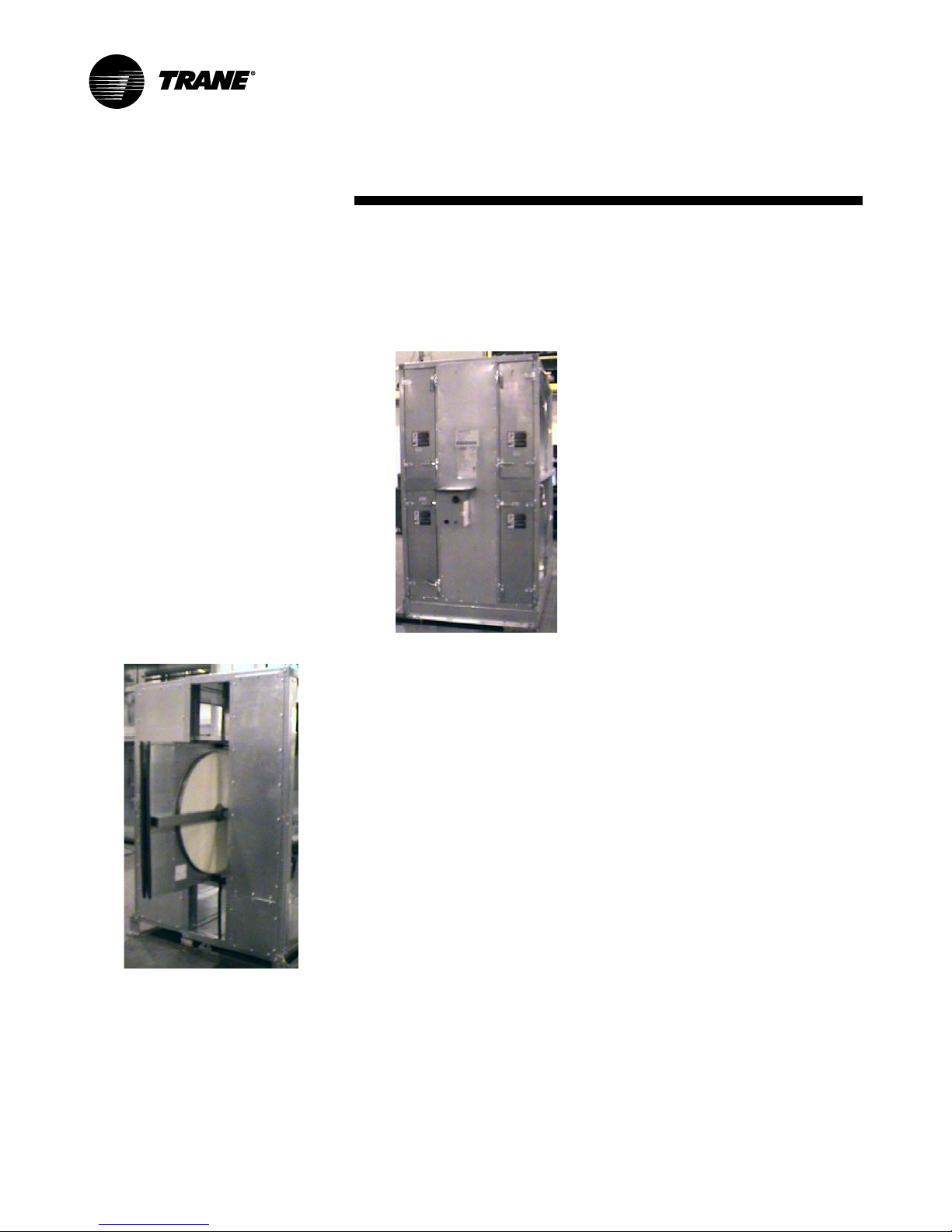
The energy wheel cassette in unit
sizes 10 to 50 is permanently
installed in the module. Four access
doors are provided for cleaning and
maintenance (see Figure 2).
.
Figure 2. M-Series air handler
energy wheel module with four
access doors, sizes 10 to 50
Optional air bypass dampers may
ship with the module. If ordered,
these dampers are factory-installed
in the same bulkhead wall as the
energy wheel cassette. Optional
actuators may be attached to the
dampers.
How the Module
Arrives at the Job
Site
No Base Rail Option If the optional
base rail was not ordered, the energy
wheel module will arrive mounted to
a wood skid. The module is held on
to the skid with steel bands and/or
screws. Leave the module mounted
to the wood skid until it is ready to
install in the equipment room to help
protect it from damage during
rigging and handling. Note: The
mounting legs will be pre-installed to
the module and attached to the skid.
Take care that the legs are not
discarded. Refer to the instruction
sheets in the ship-with kit.
Base Rail Option The base rail is an
optional steel channel frame that is
used to elevate the module off the
floor or to suspend it from the
ceiling. If ordered, the base rail is
attached for unit sizes 3 to 40. The
energy wheel module will arrive
mounted on the base rail. For unit
size 50, the base rail is shipped
banded to a separate skid for field
installation. If separate, wood skid
boards are attached to the bottom of
the base channels. Leave the wood
skid boards attached to the base rail
until it is ready to install in the
equipment room to protect it from
damage during rigging and
handling.
®
Amowrap
openings of the module are
protected by Amowrap reinforced
plastic covering. The Amowrap
covering is held on to the module
with a wood frame and sheet metal
screws. Leave the Amowrap
covering attached to the module until
it is ready to install in the equipment
room to prevent debris from entering
the module.
Hardware Kit Hardware kits ship
inside the module. The kits contain
gasketing, brackets, and screws,
which are used when fastening the
module to the air handler. Keep the
hardware kit with the energy wheel
module until it is ready to install in
the equipment room.
Access Doors
secured for shipment with a bracket.
Remove and discard bracket when
the module arrives.
Covering The large
Access doors are
4 CLCH-SVX02C-EN

Description
Receiving
Inspection
Upon receipt of the module, inspect
it for damage that may have occurred
during shipment. Report damage
immediately to the freight company
and make a note on the shipping tally
sheet.
• Remove the access door
shipping clamps (flat brackets)
and check for internal, hidden
damage. Concealed damage
must be reported within 15
days of receipt. Trane is not
responsible for shipping
damage.
• Locate the bags containing the
hardware kits.
• Examine the energy wheel
motor, drive, and energy
transfer segments for damage.
• Cut the banding loose from the
skid. Do not remove the module
from the skid at this time.
• Manually rotate the energy
wheel to ensure free movement
of the bearings and drive.
Storage
Trane recommends indoor storage of
the module. If outdoor storage is
necessary, select a solid, welldrained area. Concrete or black top
surfaces are recommended. If
concrete or black top is not available,
set the module on wood timbers to
prevent dirt, mud, snow, etc. from
getting into the module. Cover the
module with a canvas tarp. Covering
the module with clear or black plastic
sheeting is not recommended as this
material traps condensed moisture,
which can cause equipment damage
due to rust and corrosion. If
equipped with a factory-installed
starter, it will be covered with plastic
during shipping. The plastic covering
must be removed before outdoor
storage. Trane warranty does not
cover equipment damage due to
negligence during storage.
Contractors’
Responsibilities
Installing Contractor
• Unpack the module and remove
the skid or skid boards.
• Remove the Amowrap
protective covering.
Electrical and/or Controls
Contractor
• Provide high voltage power to
the energy wheel. For voltage
requirements, see Table 3 in
“Wiring” on page 9.
• Provide and install a starter or
starting contactor, disconnect,
fuses, etc. (as required by local
codes) for the energy wheel
motor if a factory-installed
starter is not provided.
• Provide, install, and connect
damper actuators if the module
is equipped with optional air
bypass dampers less the
actuators.
• Provide, install, and connect
temperature sensors for energy
wheel controls if the module is
not equipped with factoryinstalled sensors.
• Provide, install, and connect
required control devices for
energy wheel controls if the
module is not equipped with
factory-installed devices, or
connect to factory-installed
devices that were not ordered
factory-wired.
CLCH-SVX02C-EN 5
• Rig and/or move the module
into the equipment room. The
contractor must provide slings,
spreader bars, clevis hooks,
pins, etc., for rigging.
• Provide a reasonably level floor,
pad, or ceiling suspension
system for the air handler.
• Assemble the energy wheel
module to the air-handling
system.
Installation
WARNI NG
Improper Unit Lift!
Do not lift the unit from top! Lift from
lifting lugs only located at bottom of
unit. Test lift unit approximately 24
inches to verify proper center of
gravity lift point. To avoid dropping
of unit, reposition lifting point if unit
is not level. Failure to properly lift
unit could result in death or serious
injury or possible equipment or
property-only damage.
WARNI NG
Heavy Objects!
Follow good lifting practices before
lifting the unit, such as estimating
center of gravity and test lifting the
unit to check for balance and
stability.
or slings) used to lift the unit must be
capable of supporting the entire
weight of the unit. Lifting cables
(chains or slings) may not be of the
same length. Adjust as necessary for
even unit lift. Other lifting
arrangements could cause
equipment or property-only damage.
Failure to properly lift unit could
result in death or serious injury.
Each of the cables (chains
Service Clearance
Recommendations
For unit sizes 3 to 8, locate the
module to allow removal of the
energy wheel cassette through the
access panel. Typically, the minimum
clearance is equal to the module
width plus 12 inches.
Rigging/Lifting
Refer to the M-Series air handler
installation and maintenance
manual, CLCH-SVX03B-EN, for
instructions on equipment rigging
and lifting. This manual ships inside
the air handler fan module.
Module Weights and
For unit sizes 10 to 50, locate the
module to allow all access doors to
open fully. Make provisions for
temporary access on either side of
the module for complete removal of
the cassette/wheel frame. This would
be required if complete replacement
of the entire cassette/wheel
assembly were needed. The
minimum recommended clearance
for this is equal to the module width
plus 12 inches.
Local electrical code clearance
requirements must be considered
when a factory-installed starter is
provided.
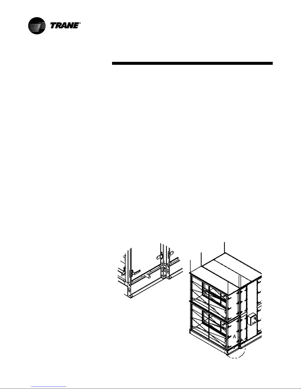
.
Figure 3. Use all lifting lugs when suspending energy wheel modules
Dimensions
Refer to Trane catalog CLCH-PRC006EN or equipment submittals for
module weights and dimensions.
Suspending Modules with
Base Rails
When suspending an energy wheel
module, it is required to suspend it
from all lifting lungs on both the
energy wheel module and any
adjoining modules (see Figure 3).
6 CLCH-SVX02C-EN
 Loading...