

Page 1
Engineering Bulletin
Starters, Drives, and Electrical Components
for CenTraVac™ Chillers
Models: CVHE, CVHF, CVHG, CDHF, CDHG
Only qualified personnel should install and service the equipment. The installation, starting up, and
servicing of heating, ventilating, and air-conditioning equipment can be hazardous and requires specific
knowledge and training. Improperly installed, adjusted or altered equipment by an unqualified person could
result in death or serious injury.When working on the equipment, observe all precautions in the literature
and on the tags, stickers, and labels that are attached to the equipment.
December 2011 CTV-PRB004-EN
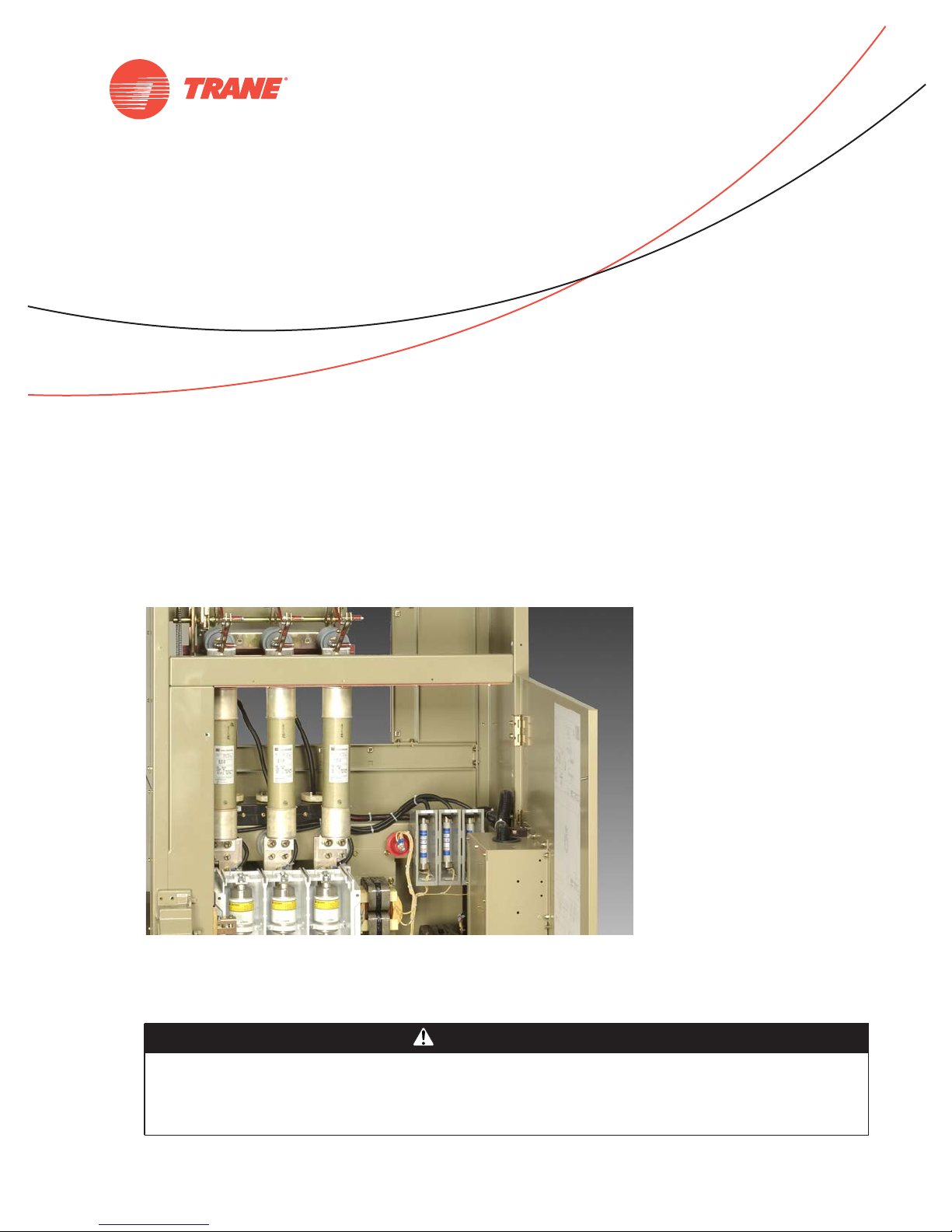
SAFETY WARNING
Page 2

Warnings, Cautions and Notices
Warnings, Cautions and Notices. Note that warnings, cautions and notices appear at
appropriate intervals throughout this manual.Warnings are provided to alert installing contractors
to potential hazards that could result in death or personal injury. Cautions are designed to alert
personnel to hazardous situations that could result in personal injury, while notices indicate a
situation that could result in equipment or property-damage-only accidents.
Your personal safety and the proper operation of this machine depend upon the strict observance
of these precautions.
Read this manual thoroughly before operating or servicing this unit.
ATTENTION: Warnings, Cautions and Notices appear at appropriate sections throughout this
literature. Read these carefully:
WARNING
CAUTIONs
NOTICE:
Indicates a potentially hazardous situation which, if not avoided, could result in
death or serious injury.
Indicates a potentially hazardous situation which, if not avoided, could result in
minor or moderate injury. It could also be used to alert against unsafe practices.
Indicates a situation that could result in equipment or property-damage only
accidents.
Important
Environmental Concerns!
Scientific research has shown that certain man-made chemicals can affect the earth’s naturally
occurring stratospheric ozone layer when released to the atmosphere. In particular, several of the
identified chemicals that may affect the ozone layer are refrigerants that contain Chlorine, Fluorine
and Carbon (CFCs) and those containing Hydrogen, Chlorine, Fluorine and Carbon (HCFCs). Not all
refrigerants containing these compounds have the same potential impact to the environment.
Trane advocates the responsible handling of all refrigerants-including industry replacements for
CFCs such as HCFCs and HFCs.
Responsible Refrigerant Practices!
Trane believes that responsible refrigerant practices are important to the environment, our
customers, and the air conditioning industry. All technicians who handle refrigerants must be
certified.The Federal Clean Air Act (Section 608) sets forth the requirements for handling,
reclaiming, recovering and recycling of certain refrigerants and the equipment that is used in these
service procedures. In addition, some states or municipalities may have additional requirements
that must also be adhered to for responsible management of refrigerants. Know the applicable
laws and follow them.
Proper Field Wiring and Grounding Required!
All field wiring MUST be performed by qualified personnel. Improperly installed and grounded
field wiring poses FIRE and ELECTROCUTION hazards. To avoid these hazards, you MUST
follow requirements for field wiring installation and grounding as described in NEC and your
local/state electrical codes. Failure to follow code could result in death or serious injury.
© 2011Trane All rights reserved CTV-PRB004-EN
WARNING
Page 3

Warnings, Cautions and Notices
WARNING
Personal Protective Equipment (PPE) Required!
Installing/servicing this unit could result in exposure to electrical, mechanical and chemical
hazards.
• Before installing/servicing this unit, technicians MUST put on all Personal Protective
Equipment (PPE) recommended for the work being undertaken. ALWAYS refer to appropriate
MSDS sheets and OSHA guidelines for proper PPE.
• When working with or around hazardous chemicals, ALWAYS refer to the appropriate MSDS
sheets and OSHA guidelines for information on allowable personal exposure levels, proper
respiratory protection and handling recommendations.
• If there is a risk of arc or flash, technicians MUST put on all Personal Protective Equipment
(PPE) in accordance with NFPA 70E or other country-specific requirements for arc flash
protection, PRIOR to servicing the unit.
Failure to follow recommendations could result in death or serious injury.
Trademarks
Adaptive Frequency, CenTraVac, Duplex,TOPSS,Tracer AdaptiView,Tracer Summit,Trane, and the
Trane logo are trademarks or registered trademarks ofTrane in the United States and other
countries.Trane is a business of Ingersoll Rand. All trademarks referenced in this document are the
trademarks of their respective owners.
Cutler-Hammer is a registered trademark of Eaton Corporation.
CTV-PRB004-EN 3
Page 4

Table of Contents
Introduction ............................................................ 6
About Starters .......................................................... 7
What a Starter Does ................................................ 7
Motor Types and Voltage Classes ........................................ 8
Voltage Classes .................................................... 8
Motors ........................................................... 8
Chiller Selection and Electrical Specification ............................. 10
Standard Components of Trane Starters ............................. 10
Chiller Selection Report ............................................ 10
Motor Protection ...................................................... 13
Low-Voltage Starter Types ............................................. 17
Low Voltage—Wye-Delta ........................................... 18
Low Voltage—Solid-State .......................................... 22
Low Voltage—Unit-Mounted Adaptive Frequency Drive ................ 25
Low Voltage—Remote-Mounted Adaptive Frequency Drive ............. 28
Wye-Delta Starters ........................................... 18
Solid-State Starters ........................................... 22
Medium-Voltage Starter Types (2,300–6,600 Volts) ....................... 31
Medium Voltage—Across-the-Line (2.3–6.6 kV) .......................32
Across-the-Line Starter (2,300–6,600 volts) ........................ 32
Medium Voltage—Primary Reactor (2.3–6.6 kV) ....................... 35
Primary Reactor Starter (2,300–6,600 volts) ....................... 35
Medium Voltage—Autotransformer (2.3–6.6 kV) ...................... 38
Autotransformer Starter (2,300–6,600 volts) .......................38
Unit-Mounted Starter Top Hat—NEC 2005 Code Requirement ........ 40
Medium Voltage—Remote-Mounted Adaptive Frequency Drive ......... 42
Chiller Unit Control Features for the AFD ......................... 43
Medium-Voltage Starter Types (10,000–13,800 Volts) .....................45
Medium Voltage—Across-the-Line (10–13.8 kV) ....................... 45
Across-the-Line Starter (10,000–13,800 volts) ...................... 45
Medium Voltage—Primary Reactor (10–13.8 kV) ...................... 47
Primary Reactor Starter (10,000–13,800 volts) ..................... 47
Medium Voltage—Autotransformer (10–13.8 kV) ...................... 48
Autotransformer Starter (10,000–13,800 volts) .....................48
Electrical System—Ratings ............................................. 49
Electrical System—Design Guidelines ................................... 52
4 CTV-PRB004-EN
Page 5

Disconnect Means ............................................ 52
Short-Circuit Interruption ...................................... 53
Power Circuit Requirements ....................................54
Electrical System–Power Wire Sizing .................................... 56
Starter Options ........................................................ 61
Multiple Starter Lineups (2,300–6,600 volts) ....................... 61
Industrial-Grade Starters ...................................... 63
Glossary .............................................................. 73
CTV-PRB004-EN 5
Page 6

Introduction
This document explains key electrical concepts and starter product information relating toTrane
water chillers.Topics include voltage classes, motors, motor protection, starter types, variablefrequency drives, wire sizing, power factor correction, and electrical term definitions.
Information in this document changes frequently.To make sure you are viewing the most recent
version, be sure to download the latest copy available on e-Library.
Dimensional data
Job specific submittals are always the best source of dimensional data. General starter dimensions
are shown with the descriptions of each starter type in this document.
Wiring information
The best source for additional information is the Installation, Operation, and Maintenance manual
shipped with the chiller. Field connection diagrams are also available on the website.
All unit-mounted starters are designed for top-entry line power only. Remote starters are typically
designed for top-entry line power and a bottom exit for load wires.The medium-voltage starter
submittals show conduit space for alternate wiring options. Additional wiring options may be
available.
For your convenience, power wire sizing charts for various voltages and conduit combinations are
provided.
Fuse and circuit breaker sizing
Proper sizing of fuses and circuit breakers upstream of the starter is the responsibility of the
customer or the electrical engineer. Disconnects and circuit breakers are options that can be
installed within theTrane
or local code requirements for installation of overcurrent devices.
Important: Trane, in presenting electrical information and system design and application
concepts, assumes no responsibility for the performance or desirability of any
resulting system design. Design of the HVAC and related electrical system is the
prerogative and responsibility of the engineering professional.Trane has a policy of
continuous product and product information improvement and reserves the right to
changedesign and specifications without notice. Consult the chiller submittal for the
most up-to-date information as applied to the specific chiller under consideration.
®
starters. WhatTrane would install may not necessarily satisfy UL, NEC,
®
6 CTV-PRB004-EN
Page 7

About Starters
What a Starter Does
Electric, centrifugal, water-cooled chillers use relatively large induction motors to drive the
compressors.These motors use a control device to connect to and disconnect from the electrical
power source.These control devices are referred to as combination controllers or, most commonly,
as motor starters. Variable-frequency drives or Adaptive Frequency™ Drives (AFDs) also serve as
motor starters, but their capabilities extend beyond starting and stopping the motor.
There are three main functions of the motor starter.The first function is to serve as the link between
the chiller’s motor and the electrical distribution system. It is used during the starting and stopping
sequence.
Starting an induction motor from standstill causes a large electrical current draw for a few seconds.
The extra current is used to develop the required torque to get the compressor motor running at
full speed.The initial rush of current decreases as the compressor motor ramps up to full speed,
and is commonly referred to as inrush current.
The second function of the starter is to keep the initial current inrush below a specified level.Third,
the starter communicates with the unit controller to coordinate motor protection.
Starters can be as simple or as complex as necessary to meet various engineering specifications
and/or customer needs. A variable-speed drive can provide starter functions, among other things
(see “Low Voltage—Unit-Mounted Adaptive Frequency Drive,” p. 25 and “Medium Voltage—
Remote-Mounted Adaptive Frequency Drive,” p. 42). It will be classified as a starter type for the
purposes of this document.
Several voltage classes and starter types are available as indicated on the chart below. Each one
is described in greater detail in this document.
Table 1. Trane CenTraVac chiller starter choices
Low Voltage (208–600 V) Medium Voltage (2,300–6,600 V)
Remote-Mounted Unit-Mounted Remote-Mounted Unit-Mounted Remote-Mounted
Wye-Delta
Up to 1,700 amps
Solid-State
(Up to 1,120 amps with
disconnect or circuit breaker
required)
Adaptive Frequency
Drive
460/480/575/600 V
Up to
1,360 amps (460/480 V)
1,120 amps (575/600 V)
Wye-Delta
Up to 1,316 amps
(Up to 1,120 amps with
disconnect/circuit breaker
option)
Solid-State
(Up to 1,120 amps with
disconnect or circuit breaker
required)
Adaptive Frequency
Drive
Up to 1,210 amps
Circuit breaker standard
460–480 V
Across-the-Line
Up to 360 amps
Isolation switch, power
fuses standard
Primary Reactor
Up to 360 amps
Isolation switch, power
fuses standard
Autotransformer
Up to 360 amps
Isolation switch, power
fuses standard
Adaptive Frequency
Drive
Up to 250 amps
Isolation switch, power
fuses standard
Across-the-Line
Up to 288 amps
Isolation switch, power
fuses standard
Primary Reactor
Up to 205 amps
Isolation switch, power
fuses standard
Autotransformer
Up to 205 amps
Isolation switch, power
fuses standard
Medium Voltage
(10–13.8 kV)
Across-the-Line
Up to 94 amps
Isolation switch, power
fuses standard
Primary Reactor
Up to 94 amps
Isolation switch, power
fuses standard
Autotransformer
Up to 94 amps
Isolation switch, power
fuses standard
CTV-PRB004-EN 7
Page 8
MotorTypes and Voltage Classes
Voltage Classes
There are two primary voltage classes typically used in the water-cooled chiller industry: low and
medium. For centrifugal chillers this is generally restricted to three-phase power only.
Low voltage ranges from 208 to 600 volts. Starters and frequency drives in this voltage range
include sizes up to 1,700 amps.
Medium voltage has two main voltage groups. One ranging from 2,300 to 6,600 volts and the other
ranging from 10,000 to 13,800 volts. Starters in this class have sizes up to 360 amps and 94 amps
respectively.
For a given power (kW), the higher the voltage the lower the amperage.The voltage is typically
established prior to creating the job plans and specifications.
Motors
A centrifugal motor is a relatively simple motor. Specifically, it is referred to as a three-phase,
squirrel-cage, 3,600-rpm, alternating-current induction motor with two-pole construction.
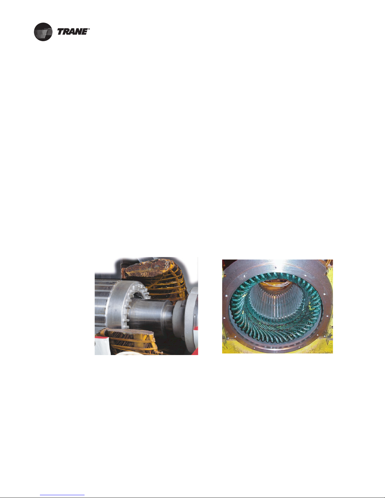
The squirrel-cage motor consists of a fixed frame, or stator, carrying the stator windings and a
rotating member called the rotor. Figure 1 shows a cutaway of a typical low-voltage motor.The
rotor is built by rigidly mounting steel laminations to the motor shaft.The motor winding consists
of aluminum bars that are die-cast into slots in the rotor.The aluminum bars are connected at each
end by a continuous ring.This skeleton of rotor bars with end rings looks like a squirrel cage and
gives the motor its name.
Figure 1. Low-voltage motor Figure 2. Medium-voltage motor
Stator
Stator
Squirrel-cage
Squirrel-cage
Rotor shaft
Rotor shaft
Stator
Stator
In a three-phase motor, three windings on the stator connect to a motor terminal board, and
ultimately to the power grid via the starter.When the polyphase alternating current flows through
the stator winding it produces a rotating magnetic field.The resulting magnetic forces exerted on
the rotor bars cause the rotor to spin in the direction of the stator field.The motor accelerates until
a speed is reached corresponding to the slip necessary to overcome windage and friction losses.
This speed is referred to as the no-load speed.
Low-voltage motors typically have six motor terminals to electrically connect the motor in a wye
(star) or delta configuration. Most low-voltage motors are random-wound motors, but larger
amperage higher horsepower motors are form wound for better heat dissipation. Connecting links
can be used to convert the six motor electrical connections to three connections.
Medium-voltage motors (2,300–6,600 V) have three motor terminals. Figure 2 shows a typical
medium-voltage motor minus the rotor shaft.You can visually compare most low- and medium-
8 CTV-PRB004-EN
Page 9

MotorTypes and Voltage Classes
voltage motors. Medium-voltage motors are always form wound and you can see that the
insulation is thicker and the windings are more evenly spaced.
Figure 3. Ceramic insulators on medium-voltage motor (10-13.8 kV)
Medium-voltage motors (10–13.8 kV) have the same design and construction attributes as other
medium-voltage motors with some externally visible differences. Ceramic insulators and larger
spacing of the motor terminals are commonly found on typical 10–13. kV medium-voltage motors.
Internally, these motors are form wound and structurally similar to other medium-voltage motors.
The ceramic insulators combined with the larger spacing between the motor terminals help
prevent electrical arcing.
Higher voltage motors and starters are being used in large chiller plants where incoming line power
makes 10–13.8 kV accessible. In some cases, higher voltage chillers allow for the elimination of
electrical components with their associated space requirements and energy losses. In particular,
chiller installations with on-site or dedicated power generation, such as district cooling, higher
education, hospitals, industrials, and airports have opportunities for electrical distribution system
simplification and energy savings.
Benefits of 10,000–13,800 volts include:
• No need for step-down transformer
• No transformer losses
• Higher uncorrected power factor
• Reduced electrical design and labor
• Reduced mechanical room space
Note: Motors and starters at 10,000–13,800 volts typically cost more, and the motor efficiency is
lower than 2,300–6,600-volt motors.
Motors are available in specific power sizes, which are rated in kilowatts or horsepower.The
TOPSS™ computer software selection program selects the proper motor to meet the specific
cooling duty of the application.
CTV-PRB004-EN 9
Page 10

Chiller Selection and Electrical Specification
Standard Components of Trane Starters
• A 4 kVA control-power transformer (CPT) supports all of the chiller auxiliary power needs—
3 kVA control-power transformer supplied with AFDs.
• Primary and secondary current transformers (CTs) support the overload and momentary power
loss protection functions of the unit controller.This allows amps per phase and percent amps
to be displayed at the unit controller.
• Potential transformers (PTs) support motor protection functions such as under/overvoltage
within the unit controller.This allows voltage per phase, kilowatts, and power factor to be
displayed at the unit controller.
• Grounding provisions are standard.
• A terminal block for line power connection is standard. Load-side lugs are standard for remote
starters.The lug sizes and configuration are shown on the submittal drawing.TheTrane
has a circuit breaker as standard. Medium-voltage starters have provisions for a bolted
connection.
Chiller Selection Report
The following terms are found on a typicalTOPSS product report. Review the example selection
output report shown in Figure 4, p. 12.
Electrical information
Usually the primary RLA (incoming line), compressor motor RLA, and kW of the chiller are used as
nameplate values. In this section, we will review the typical electrical data presented on the
selection report.
®
AFD
A. Motor size (kW). The motor size is listed on the program report based on its output kW.The
output kW is the motor’s full, rated power capacity.There is an amperage draw associated with the
motor size called full-load amps (FLA). FLA is the amperage the motor would draw if it were loaded
to its full rated capacity, i.e. the motor size. The FLA is not available from the chiller selection
program, but it can be obtained from motor data sheets upon request.
B. Primary power (kW). The primary power is the power the chiller uses at its design cooling
capacity.The primary power will always be less than or equal to the motor size.
C. Motor locked-rotor amps (LRA). There is a specific locked-rotor amperage value associated
with each specific motor.This is the current draw that would occur if the rotor shaft were
instantaneously held stationary within a running motor. LRA is typically six to eight times the motor
full-load amps (FLA). LRA is also used commonly in discussing different starter types and the
inrush amperages associated with the motor start. For example, a wye-delta starter will typically
draw approximately 33 percent of the motor LRA to start. A solid-state starter will draw
approximately 45 percent of the motor LRA to start.
D. Primary rated-load amps (RLA [incoming line]). The RLA is also commonly referred to as
the selection RLA or unit RLA.This is the amperage that is drawn on the line side when the chiller
is at full cooling capacity. Nameplate RLA (usually the same as primary RLA [incoming line]) is the
key number used to size the starter, disconnects, and circuit breaker. Primary RLA (incoming line)
is also the value used to determine the minimum circuit ampacity (MCA) for sizing conductors.
Primary RLA (incoming line) is always less than or equal to the motor full-load amps (FLA).
E. Compressor motor RLA. This is the amperage between the motor and starter or AFD. If the
unit is a starter, the compressor motor RLA will be almost identical to the primary RLA (incoming
line). If the unit is an AFD, typically, the compressor motor RLA will be larger.This value is used
to size the AFD.The primary RLA (incoming line) is lower due to the improved power factor of the
AFD.
10 CTV-PRB004-EN
Page 11

Chiller Selection and Electrical Specification
F. Minimum circuit ampacity (MCA). This term appears on the chiller nameplate and is used
by the electrical engineer to determine the size and number of conductors needed to bring power
to the starter.
MCA = 1.25 x (Primary RLA [incoming line])+
… with this number rounded up to the next whole number. Said another way, the MCA is
125 percent of the motor design primary RLA (incoming line) plus 100 percent of the amperage of
other loads (sump heater, oil pump, purge, etc.).The MCA is listed on the chiller selection report.
Power cable sizes and conduits are discussed in “Electrical System–PowerWire Sizing,” p. 56. If the
AFD is a remote, free-standing AFD, the MCA will be based on the compressor motor RLA.
(
4000
volts
motor
)
G. Maximum overcurrent protection (MOP or MOCP). The MOP appears on the chiller
nameplate.The electrical engineer often wants to know the MOP when the chiller is selected for
sizing fuses and upstream circuit breakers. Understand that the MOP is a maximum, NOT a
recommended fuse size. Improperly sized circuit breakers or fuses can result in nuisance trips
during the starting of the chiller or insufficient electrical protection. MOP is also NOT used to size
incoming power wiring—the MCA is used for this purpose.
CTV-PRB004-EN 11
Page 12
Chiller Selection and Electrical Specification
8QLW,QIRUPDWLRQ
&9+(
+]
+]
\
6
6
7(&8
7(&8
7ZRSDVVHYDSZDWHUER[
7ZRSDVVFRQGZDWHUER[
'HVLJQ,QIRUPDWLRQ
WRQV
\
OE
N:
OE
N:WRQ
\
OE
N:WRQ
1R
1R
8QLWPRXQWHGORZYROWDJH$)'
$
6WDQGDUGFRROLQJ
0%K
0%K
$
(YDSRUDWRU,QIRUPDWLRQ
)
S
S
IW+2
JSP
ZDWHU
)
1$
JSPWRQ
\
QRQPDULQH
SVLJ
KUVTIWGHJ)%WX
&RQGHQVHU,QIRUPDWLRQ
)
IW+2
JSP
ZDWHU
)
S
1$
JSPWRQ
QRQPDULQH
KUVTIWGHJ)%WX
SVLJ
(OHFWULFDO,QIRUPDWLRQ
$
$
$
\
$
$
Figure 4. Excerpt from chiller selection report
0RGHO
,PSHOOHUVL]H
0RWRUVL]H
0RWRUIUHTXHQF\
,QFRPLQJOLQHIUHTXHQF
(YDSVKHOOVL]H
(YDSEXQGOHVL]H
(YDSWXEHW\SH
(YDSWXEHWKLFNQHVV
(YDSSDVVHV
A
&RROLQJFDSDFLW
3ULPDU\SRZHU
3ULPDU\HIILFLHQF
13/9
/RZYROWDJH$)'W\SH
B
&RPSUHVVRUVL]H
2ULILFHVL]H
0RWRUYROWDJH
,QFRPLQJOLQHYROWDJH
&RQGVKHOOVL]H
&RQGEXQGOHVL]H
&RQGWXEHW\SH
&RQGWXEHWKLFNQHVV
&RQGSDVVHV
+&)&UHIULJHUDQWFKDUJH
6KLSSLQJZHLJKW
2SHUDWLQJZHLJKW
)UHHFRROLQJRSWLRQ
*UHHQ6HDOFHUWLILFDWLRQ
8QLWKHDWUHMHFWHGWRDPELHQW
)'KHDWUHMHFWHGWRDPELHQW
(YDSOHDYLQJWHP
(YDSIORZUDWH
(YDSHQWHULQJWHPS
(YDSIORZFDSDFLW
(YDSIRXOLQJIDFWRU
&RQGHQWHULQJWHPS
&RQGIORZUDWH
&RQGOHDYLQJWHP
&RQGIORZFDSDFLW\
&RQGIRXOLQJIDFWRU
0RWRU/5$
3ULPDU\5/$,QFRPLQJOLQH
8QFRUUHFWHGSRZHUIDFWRU
SSOLFDWLRQW\SH
(YDSSUHVVXUHGUR
(YDSIOXLGW\SH
(YDSIOXLGFRQFHQWUDWLRQ
(YDSZDWHUER[W\SH
(YDSZDWHUER[SUHVVXUH
C
D
&RQGSUHVVXUHGURS
&RQGIOXLGW\SH
&RQGIOXLGFRQFHQWUDWLRQ
&RQGZDWHUER[W\SH
&RQGZDWHUER[SUHVVXUH
&RPSUHVVRUPRWRU5/$
0LQFLUFXLWDPSDFLW
0D[RYHUFXUUHQWSURWHFWLRQ
E
F
G
12 CTV-PRB004-EN
Page 13

Motor Protection
Historically, motor protection was provided in the starter by some type of monitoring system.
Starter manufacturers usually provide a full range of optional equipment mounted on the starter.
Eaton Cutler-Hammer
Today,Trane provides most of the key motor protection and metering functions (see Table 2, first
column) within the chiller microprocessor control panel as standard. Having the motor control and
chiller control in one panel provides better integration and optimization of the two control systems.
For example, the chiller controller can unload the chiller when approaching an overload “trip”
point, so that the chiller stays online.
Table 2 and Table 3, p. 14 can be used to compare the standard electrical features of the chiller
controller with those of other common Eaton Cutler-Hammer
Additional starter-mounted metering and motor protection may not be required and could be
considered redundant.These devices are not available for AFDs.
Table 2. Protection and functions by motor packages
®
offers IQ metering and motor protection products for their starters.
®
starter-only-mounted devices.
Protection Functions
Communications Optional Optional Optional Optional
Ground fault Optional
Long acceleration Standard Standard N/A N/A
Maximum number of starts Standard Standard N/A N/A
Momentary power loss (distribution fault) Standard N/A N/A N/A
Motor overload Standard Standard N/A N/A
Motor winding temperature Standard
Over temperature Standard N/A N/A N/A
Overvoltage Standard
Phase imbalance Standard Standard N/A Standard
Phase loss Standard Standard N/A Standard
Phase reversal Standard N/A N/A Standard
Run timer Standard Standard N/A N/A
Separate alarm levels
Surge capacitor/lightning arrestor Optional N/A N/A N/A
Undervoltage Standard
(a)The MP 3000 features Intel-I-Trip overload protection, enhanced custom trip curve development, UL 1053 ground fault, and advanced data logging and
diagnostics.
(b)For low voltage, a Trane-supplied circuit breaker or non-fused disconnect is also required when ground fault is specified.
(c) The chiller controller monitors the motor temperatures of all three phases with one resistance temperature detector (RTD) per phase
(d)For this option, add one or two sets (three RTDs per set) of 100-ohm platinum RTDs to the motor. Contact La Crosse Field Sales Support.
(e) Under/over phase-voltage sensors include volts per phase, kW, power factor, kWh, and under/overvoltage. A required pick on medium-voltage starters.
(f) Three alarm levels are used: warning only, nonlatching (auto-reset), and latching (manual reset required).
(f)
Tracer
AdaptiView MP 3000
(b)
(c)
(e)
Standard Standard N/A N/A
(e)
Standard N/A N/A
Optional
N/A N/A Standard
N/A N/A Standard
(d)
(a)
IQ 150 IQ DP 4130
N/A N/A
CTV-PRB004-EN 13
Page 14

Motor Protection
Table 3. Starter ONLY: metering functions and accuracies
Metering Functions Tracer AdaptiView MP 3000
Ampere demand N/A N/A Standard (±0.25%) Standard (±0.3%)
Current (%RLA) Standard (±3% to ±7%) Standard N/A N/A
Current (3-phase) Standard (±3%) Standard Standard (±0.25%) Standard (±0.3%)
Voltage (3-phase) Standard
Frequency N/A N/A Standard Standard
Harmonic distortion current N/A N/A N/A Standard (31
Harmonic distortion voltage N/A N/A N/A Standard (31
Kilowatt Standard
Power factor Standard
VA (volt-amperes) N/A N/A Standard (±0.5%) Standard (±0.6%)
VA demand N/A N/A Standard (±0.5%) Standard (±0.6%)
VA hours N/A N/A Standard (±0.5%) Standard
VARs (volt-amperes reactive) N/A N/A Standard (±0.5%) Standard (±0.6%)
VAR demand N/A N/A Standard (±0.5%) Standard (±0.6%)
VAR-hours N/A N/A Standard (±0.5%) Standard
Watt, see Kilowatt Standard
Watt demand Standard N/A Standard (±0.5%) Standard (±0.6%)
Watt-hours Standard N/A Standard (±0.5%) Standard
(a)The MP 3000 features Intel-I-Trip overload protection, enhanced custom trip curve development, UL 1053 ground fault, and advanced data logging and
diagnostics.
(b)Under/over phase-voltage sensors include volts per phase, kW, power factor, kWh, and under/overvoltage. A required pick on medium-voltage starters.
(b)
(±2%) N/A Standard (±0.25%) Standard (±0.3%)
(b)
(±5%) N/A N/A N/A
(b)
(±5%) N/A Standard Standard
(b)
N/A Standard (±0.5%) Standard (±0.6%)
(a)
IQ 150 IQ DP 4130
st
)
st
)
Overload protection
Overload or overcurrent protection shields the motor from small levels of overcurrent ranging from
107 to 140 percent of the primary RLA of the chiller. In contrast, fuses and circuit breakers are used
to protect against short-circuit currents which may range to well over 100,000 amps.
Inductive loads, such as a chiller motor, behave differently than resistive loads such as electric
heaters.Their current draw is greatest at startup and corresponds to the existing load when
running. In other words, a motor operating normally draws rated amps (RLA) at rated load, fewer
amps at less-than-rated load and more amps at greater-than-rated load. It is the latter condition that
requires overload protection.
Adding an overload protection device prevents the motor from drawing more than its rated
amperage for an extended period. Basic overload devices simply open the circuit when current
draw reaches the “trip” point. More sophisticated devices attempt to restore normal motor
operating conditions by reducing the load, but will disconnect the motor if overloading persists.
As with most overload devices, the chiller controller determines the “trip time” by measuring the
magnitude of the overload. It then compares the overload to the programmed RLA “time-to-trip”
curve. At startup, the standard overload protection is bypassed for the starter’s acceleration time,
or until the motor is up to speed. Refer to Figure 5, p. 15 for the chiller controller’s overload timeto-trip curve.
14 CTV-PRB004-EN
Page 15
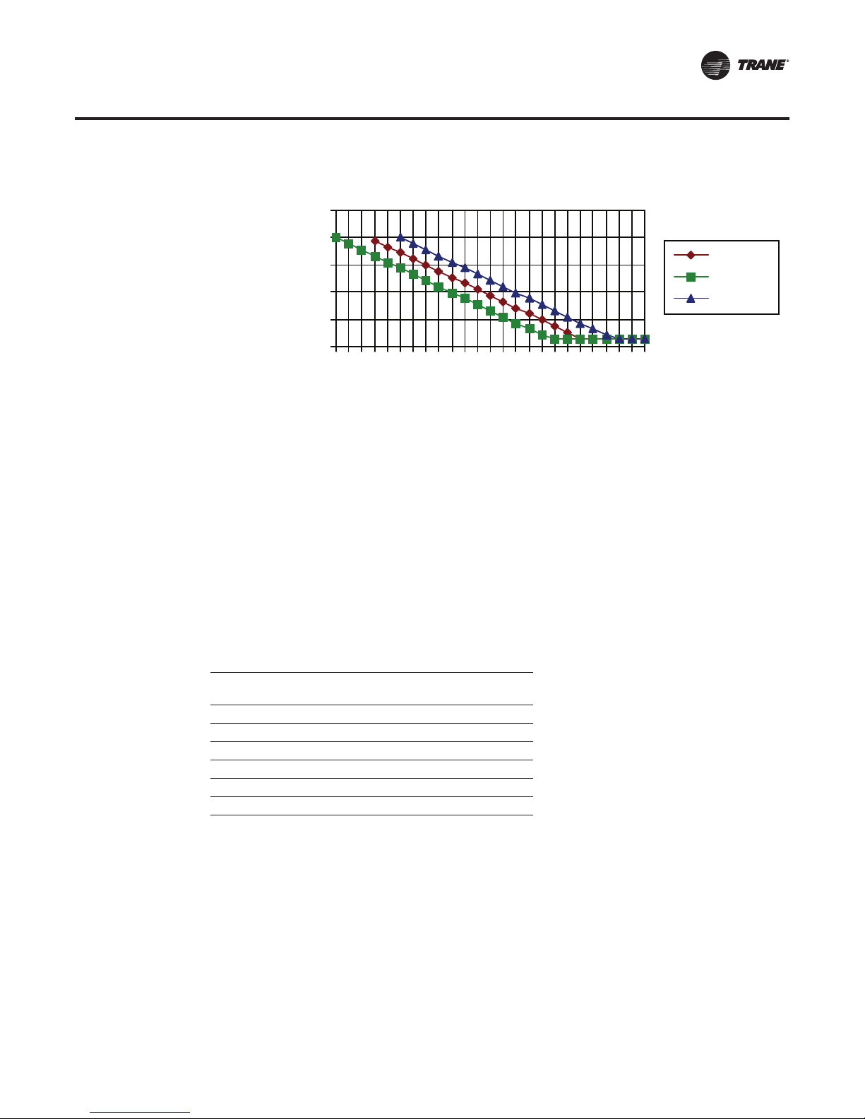
Figure 5. Tracer AdaptiView chiller controller overload time-to-trip curves
25
20
Overload Trip
Time (sec)
15
10
5
0
Motor Protection
Nominal
Minimum
Maximum
108
102
Overload situations, left unchecked by protection, can cause excessive motor heat, that can
permanently damage the windings and lead to motor failure.The time until motor damage
depends mainly on the magnitude of the overcurrent and has an inverse time versus current
relationship.The greater the overcurrent, the less time it takes to cause motor damage.
Overcurrent can be the result of motor overload, low line voltage, unbalanced line voltage, blocked
load (rotor cannot freely rotate), single phasing, bad connections, broken leads, or other causes.
It can occur in any one winding, a set of windings, or in all the motor windings.
The threshold of overcurrent is generally the primary RLA, which may be raised for service factor
or lowered due to any derating factor, such as ambient temperature or line-voltage imbalance.
Overload protection is bypassed during a start due to the high currents associated with locked rotor
and motor acceleration. Maximum allowed acceleration times per the AdaptiView unit controller
are listed in Table 4.
Table 4. Long acceleration protection
Starting Method
(starter type)
Wye-Delta 27
Solid-State 27
Variable-Frequency Drive 12
Across-the-Line 6
Primary Reactor 16
Autotransformer 16
Maximum Setting for the
Acceleration Timer (sec)
114
120
126
132
% Run-Load Amps
138
144
150
Motor overheat protection
The unit controller monitors the motor winding temperatures in each phase and terminates chiller
operation when the temperature is excessive.This feature also prevents the chiller from starting
if the motor temperature is too high.
Momentary power loss protection (distribution fault)
Momentary power losses longer than two or three line cycles will be detected and cause the chiller
to shut down, typically within six cycles. The chiller can also shut down due to excessive or rapid
voltage sags. Shutting down the chiller prevents power from being reapplied with different motor
phasing.
CTV-PRB004-EN 15
Page 16

Motor Protection
Phase failure/loss protection
The chiller will shut down if any of the three-phases of current feeding the motor drop below
10 percent RLA for 2.5 seconds.
Phase imbalance protection
Based on an average of the three phases of current, the ultimate phase-imbalance trip point is
30 percent.The RLA of the motor can be derated depending on the percent of this imbalance.The
phase-imbalance trip point varies based on the motor load.
Phase reversal protection
Detects reverse-phase rotation and shuts the chiller down (backwards rotation).
Under/overvoltage protection
The chiller is shut down with an automatic reset due to excessive line voltage ±10 percent of the
design voltage.
Short cycling protection
Prevents excessive wear on the motor and starter due to heating from successive starts.The unit
controller uses an algorithm based on a motor heating constant and a background timer
(measuring the running time since the last start).
Supplemental motor protection
This is a set of optional motor protection features, offered as a option in addition to the Enhanced
Electrical Protection Package (see “SMP, Supplemental Motor Protection—Medium voltage only
(Enhanced Electrical Protection Package option),” p. 66).
16 CTV-PRB004-EN
Page 17

Low-Voltage StarterTypes
Table 5 shows the most common low-voltage starter types available and lists their advantages and
disadvantages.Typical inrush acceleration profiles for these starters are shown in Figure 6, p. 18.
It is very uncommon to see a full-voltage starter in a low-voltage application due to the high inrush
current; however, it is represented on the chart to provide a frame of reference.
Which starter type is best?
The wye-delta starter has been around a long time and, except for an AFD, it draws the lowest
inrush current.Wye-delta starters are electromechanical and service technicians are typically more
comfortable with them.The solid-state starter is a relatively newer design compared to the wyedelta, and has a slightly higher inrush current in chiller applications.The solid-state starter inrush
can be set lower (the starter takes longer to get the motor up to speed), but it must be above the
minimum inrush required to develop the proper starting torque.The solid-state starter is
comparable in price to the wye-delta starter and has a smoother inrush curve without any current
spikes.The wye-delta’s transition spike is not long enough to set utility demand ratchets or reduce
the life of the motor.The starter type chosen ultimately depends on the application.
Table 5. Comparison of low-voltage starter types
Starter Type
(closed-transition
Wye-Delta
(Star-Delta)
Solid-State ~45 33 15%
Adaptive Frequency
Drive (AFD)
Inrush
Current
% LRA
33 33 60%
<13
(<RLA)
Percent
Rated
Torque
varies 25%
How
Often
Used Advantages Disadvantages
Trane Adaptive Frequency Drives provide motor control, but they are much more than just starters.
They also control the operating speed of the compressor-motor by regulating output voltage in
proportion to output frequency. Varying the speed of the compressor-motor can translate into
significant energy savings.
Applications that favor the use of an AFD exhibit increased operating hours at reduced condenser
water temperatures and high energy costs. However, it is important to recognize that all variablespeed drives, including theTraneAFD, require more energy near full-load design conditions, often
coinciding with the peak electrical demand of the building.This may result in higher demand
chargesand diminish the overall energy savings.An analysis of the full-year operation of the chiller
plant using an hour-by-hour simulation program that does not use blended kW and kWh energy
rates will help determine whether an AFD is appropriate for a specific application and location.
• Equal reduction of torque and
inrush current
• Low cost
• Can be unit mounted
• Gradual inrush/ramp up
• No “spike” at transition
• Price comparable to the wyedelta
• Lowest inrush current
• Better chiller efficiency at
reduced lift
• Only applicable up to
600 volts
• “Spike” at transition
• Higher level of service
expertise than wye-delta
• Higher inrush current than
wye-delta
• Starting harmonics may be an
issue
• Most expensive
• Efficiency loss at full load
• Harmonics may be an issue
Typical
Acceleration
Time
(seconds)
5–12
5–12
8–30
Unit or remote mounted?
Unit-mounted starters can save on installed cost and space, and they can be tested in the factory
and shipped on the chiller in a NEMA 1 enclosure. Remote-mounted starters provide more options
for multiple starter lineups, and may be chosen in order to implement some of the industrial starter
options such as high-fault and NEMA 12/3R.
CTV-PRB004-EN 17
Page 18
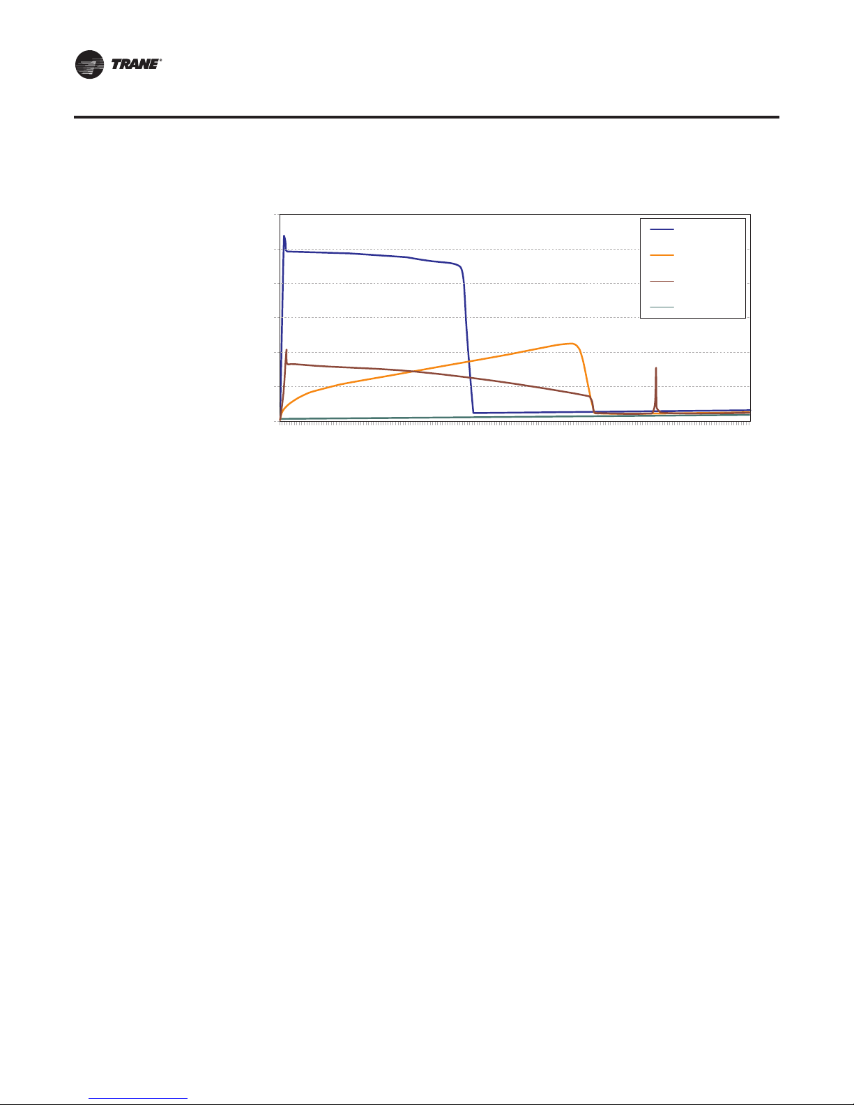
Low-Voltage StarterTypes
Figure 6. Comparison of low-voltage starting current
120
100
80
60
% LRA
40
20
0
0
Low Voltage—Wye-Delta
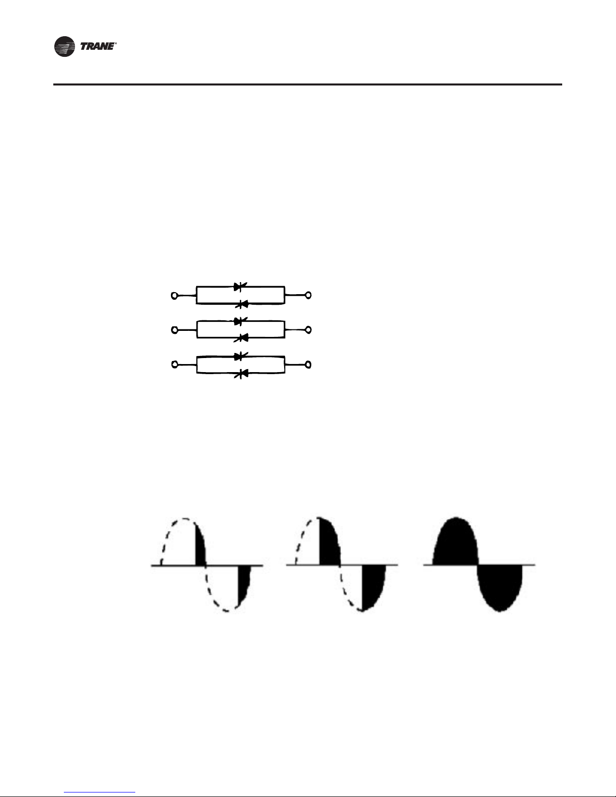
Wye-Delta Starters
One of the most common starters in the industry is the wye/star-delta. It is an electromechanical
starter initially set up in a “wye” or “star” configuration, then it transitions to a “delta”
configuration during the starting sequence.To illustrate a typical starting sequence using a generic
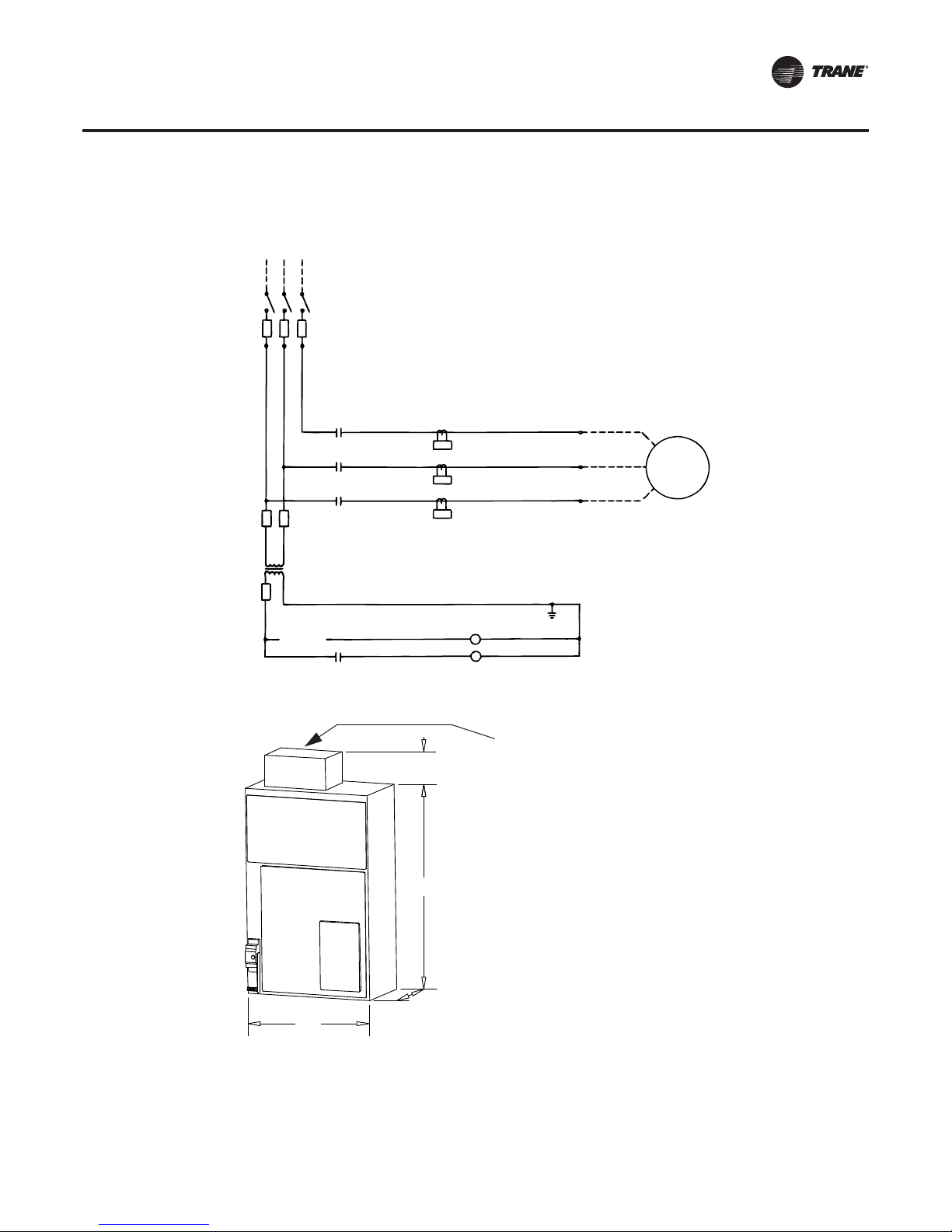
(non-Trane) schematic, refer to Figure 7, p. 19 and its “Starting sequence,” p. 19.
X-Line
Solid-State
Wye-Delta
AFD
123456789
Time (seconds)
10
18 CTV-PRB004-EN
Page 19
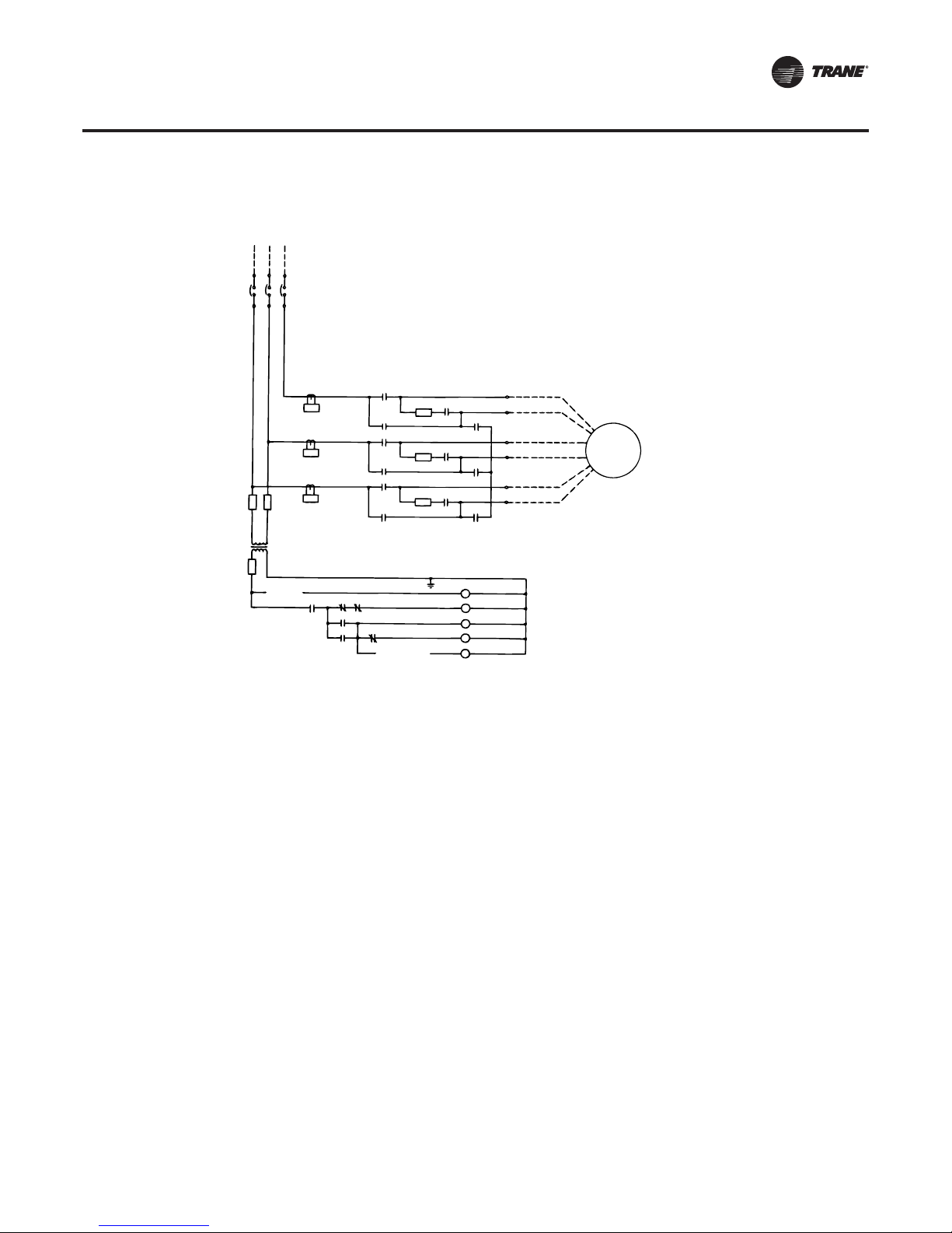
Figure 7. Simplified wye-delta wiring schematic
LINE
VOLTAGE
WYE-DELTA
STARTER WIRING
Low-Voltage StarterTypes
1A
1M
S
2M
S
1M
2M
1M
2M
1M
2M
TRANSITION
1A
R
R
R
S
1A
S
1A
S
PR
S
1M
2M
1A
MOTOR
OL
OL
OL
F
CPT
F
START-
STOP
PR
Starting sequence
1. The “start” signal from the CenTraVac controller energizes the pilot relay (PR).
2. The PR contacts close to energize the star contactor (S).
3. The S contacts close to connect the motor in the star configuration.
4. An S interlock closes to energize the start contactor (1M).
5. The 1M contacts close to connect the motor to the line.
6. A time delay relay or current monitoring device initiates transition by energizing the resistor
contactor
. 1A contacts close to connect the resistors to the line in the star configuration and in parallel with
7
the compressor
8. A 1A interlock now opens to de-energize the S contactor.
9. The S contacts open to connect the resistors and motor windings in series in the delta
configuration.
10. An S interlock closes to energize the run contactor (2M).
11. The 2M contacts close to bypass the resistors and connect the compressor motor directly to the
line
(1A).
motor.
in
the delta configuration.
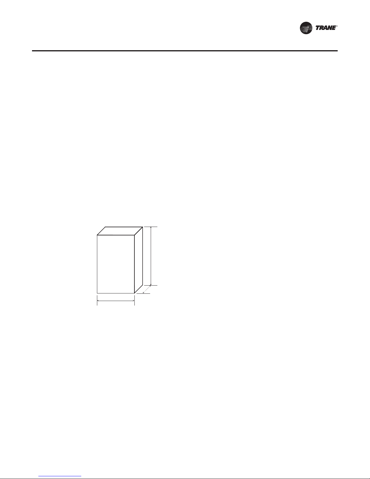
Dimensions
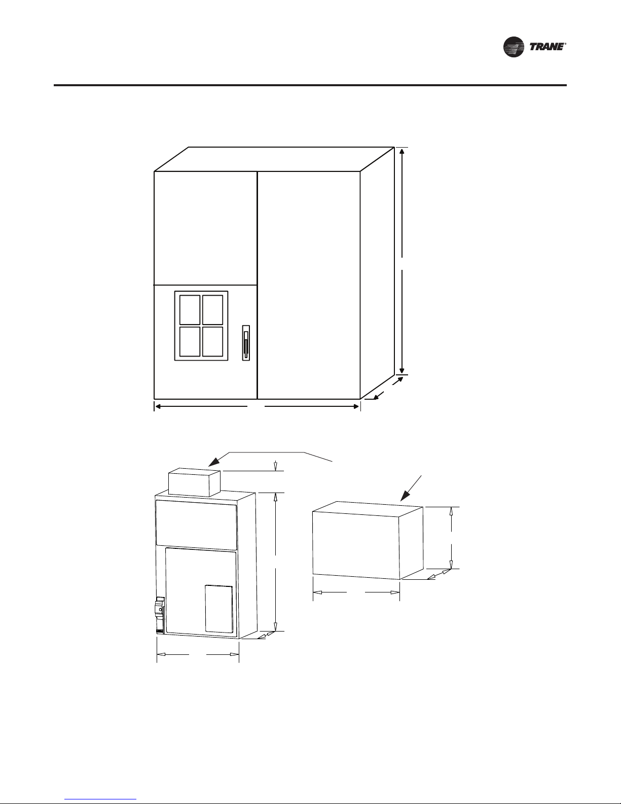
The typical unit-mounted wye-delta starter size is shown in Figure 9, p. 20. Typical remote-
mounted one-, two- and three-door starter sizes are shown in Figure 10, p. 20, Figure 11, p. 20, and
Figure 12, p. 21. Always consult the submittal drawings for as-built dimensions.
CTV-PRB004-EN 19
Page 20
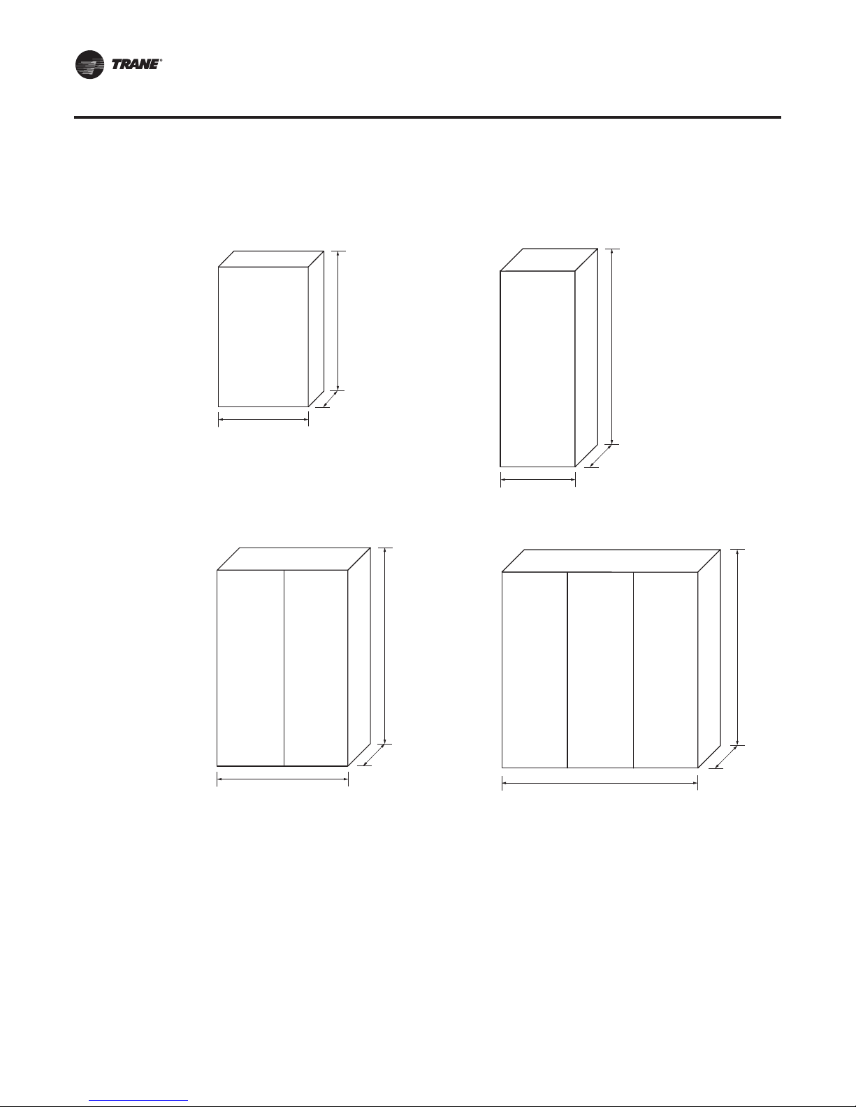
Low-Voltage StarterTypes
The one-door remote-mounted starter size is generally used for 155- to 606-amp starters with no
disconnect.The two-door size is used for 640- to 1,700-amp starters with no disconnect.The threedoor size is used for 1,385- to 1,700-amps when disconnects are included.
Figure 8. Unit-mounted WD Figure 9. Remote 1-door WD
Stator
Squirrel-cage
60”
84”
Rotor shaft
13.5”
38.5”
32”
Figure 10. Remote 2-door WD Figure 11. Remote 3-door WD
Stator
19.3”
Stator
Squirrel-cage
84”
Rotor shaft
Stator
84”
56”
20 CTV-PRB004-EN
19.3”
19.3”
84”
Page 21
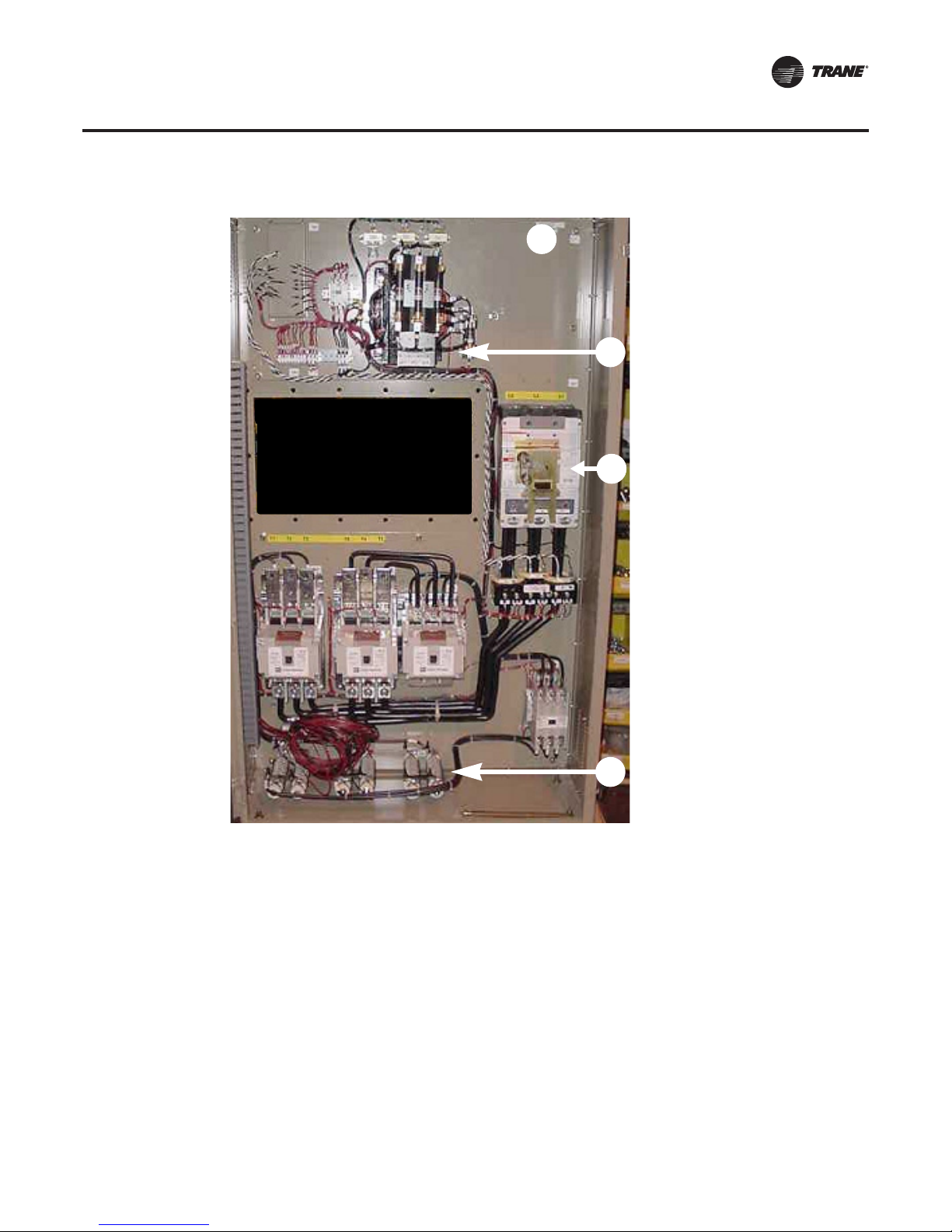
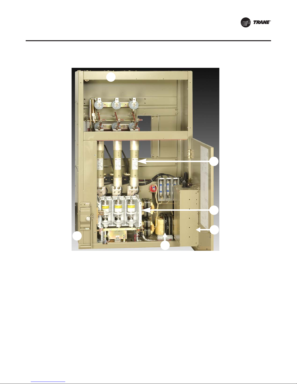
Figure 12. Unit-mounted, wye-delta starter
2
Low-Voltage StarterTypes
1. Top-entry power only
1
2
3
2. 4 kVA control-power
transformer
3. Circuit breaker (optional)
4. Transition resistors
4
Standard features
• Unit or floor mounted
• Control-power transformer
• Padlock tab for additional locking of the starter door
• Line-side connection terminal block/main lug only
• UL and CUL certified
• Environmental specification
• Designed, developed, and tested in accordance with UL 508
• NEMA 1 enclosure as standard
• Operation from sea level to 6,000 ft (1,829 m)
• Operating ambient temperature range 32°F to 104°F (0°C to 40°C)
• Relative humidity, non-condensing 5 percent to 95 percent
• Non-operating ambient temperature range -40°F to 158°F (-40°C to 70°C)
• Voltage utilization range ±10 percent
CTV-PRB004-EN 21
Page 22
Low-Voltage StarterTypes
Low Voltage—Solid-State
Solid-State Starters
TheTrane®solid-state starter produces a soft start with a gradual inrush current and no transition
spikes. It controls the starting characteristics of a motor by controlling the voltage to the motor. It
does so through the use of silicon controlled rectifiers (SCRs), which are solid-state switching
devices, and an integral bypass contactor for power control. An SCR will conduct current in one
direction only when a control signal (gate signal) is applied. Because solid-state starters use
alternating current (AC), two SCRs per phase are connected in parallel, opposing each other so that
current may flow in both directions. For three-phase loads, a full six-SCR configuration is used, as
shown in Figure 13.
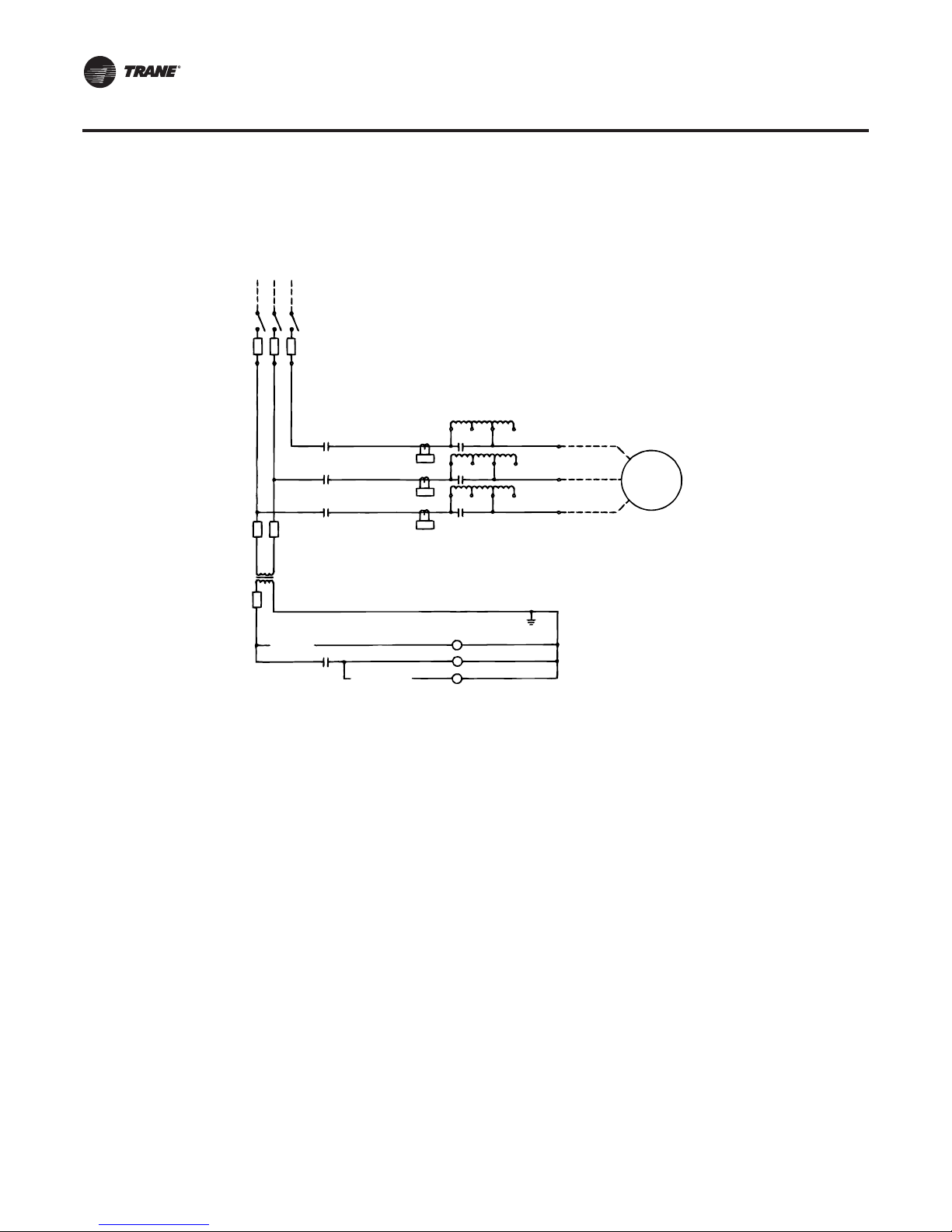
Figure 13. Six-SCR arrangement
L1
L2
L3
T1
T2
T3
Starting sequence
During starting, control of current or acceleration time is achieved by gating the SCRs “on” at
different times within the half-cycle.The gate pulses are originally applied late in the half-cycle and
then gradually applied sooner in the half-cycle. If the gate pulse is applied late in the cycle, only a
small increment of the wave form is passed through, and the output is low. If the gate pulse is
applied sooner in the cycle, a greater increment of the wave form is passed through, and the output
is increased. By controlling the SCRs ’ output voltage, the motor’s acceleration characteristic and
current inrush are controlled as illustrated in Figure 14.
Figure 14. Starting sequence wave forms
25% voltage 50% voltage full voltage
When the SCRs are fully “phased on,” the integral bypass contactors are energized.The current
flow is transferred from the power pole to the contactors.This reduces the energy loss associated
with the power pole, and extends contactor life.When the starter is given the stop command, the
SCRs are gated “full voltage” and the bypass contactor is de-energized.The current flow is
transferred from the contactors back to the power poles. Less than one second later, the SCRs are
turned off and the current flow stops.
22 CTV-PRB004-EN
Page 23
Low-Voltage StarterTypes
Features
• Unit- and floor-mounted models are available
• Control-power transformer
• Starting current is factory set and field adjustable
• Starting torque is factory set and adjustable via a voltage “notch” setting
• Six-SCR power section
• Air-cooled design with bypass contactor eliminates need for a water-cooling circuit, pump, and
heat exchanger
• Bypass contactor rated to carry 100 percent of the full-load motor phase current
• Protection from shorted SCRs and high starter heatsink temperature
• Protection from transient voltage through resistor-capacitor (RC) snubbers across SCRs and
metal oxide varistors (MOVs)
• Padlock tab for additional locking of starter door
• Line-side connection terminal block/main lug only
• UL and CUL certified
Dimensions
Typical dimensions for unit- or remote-mounted solid-state starters are shown in Figure 15. Always
consult the submittal drawings for as-built dimensions.
Figure 15. Solid-state dimensions
38.5"
60"
13.5"
CTV-PRB004-EN 23
Page 24
Low-Voltage StarterTypes
Figure 16. Unit-mounted, solid-state starter
1. Top-entry line power
1
2. Intelligent technology (IT)
controller
3. Starter control board
4. Potential transformers
5. 4 kVA control-power
transformer
2
3
4
5
Environmental specification
• Designed, developed, and tested in accordance with UL 508
• NEMA 1 enclosure as standard
• Operation from sea level to 6,000 ft (1,829 m)
• Operating ambient temperature range 32°F to 104°F (0°C to 40°C)
• Relative humidity, non-condensing 5% to 95%
• Non-operating ambient temperature range -40°F to 158°F (-40°C to 70°C)
• Voltage utilization range ±10%
24 CTV-PRB004-EN
Page 25
Low-Voltage StarterTypes
Low Voltage—Unit-Mounted Adaptive Frequency Drive
TheTrane Adaptive Frequency Drive is a refrigerant-cooled, microprocessor controlled design.The
AFD is used in lieu of a constant-speed starter and is currently available for use with 460 or 480 volts
only. Adaptive Frequency is a trademarked term for theTrane
proprietary control logic and made toTrane specifications.
About the Trane AFD
The AFD is unit-mounted and ships completely assembled, wired, and tested from the factory.The
AFD controller is designed to interface with the chiller controller. It adapts to the operating ranges
and specific characteristics of the chiller.The optimum chiller efficiency is created by coordinating
the compressor-motor speed with the compressor inlet guide vanes.The chiller controller and the
AFD controller work together to maintain the chilled-water setpoint and avoid surge. If surge is
detected, the chiller controller’s surge-avoidance logic in the chiller controller makes the proper
adjustments to move the operating point away from surge.
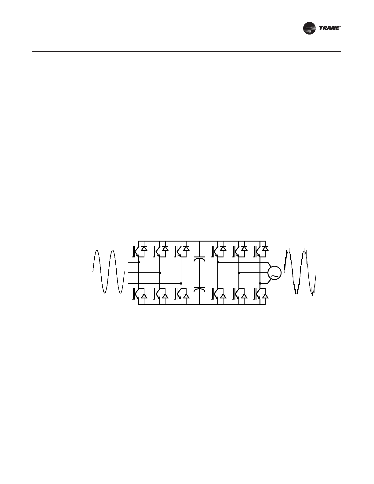
How it works
The frequency drive regulates output voltage in proportion to output frequency to maintain ideal
motor flux and constant torque-producing capability.Or put simply, a variable-speed drive controls
load-side frequency and voltage to adjust the compressor motor speed.The AFD is a voltagesource, pulse-width modulated (PWM) design. It consists of three primary power sections as
shown in Figure 17: the active rectifier, the DC bus, and the inverter.
®
variable-speed drive, using
Figure 17. AFD power sections
M
M
Rectifier DC Bus Inverter
Rectifier DC Bus Inverter
Determines line-side harmonics Determines load-side harmonics
Determines line-side harmonics Determines load-side harmonics
Rectifier (active). Takes incoming AC power, filters it with an LCL filter (not shown), and then
converts it to a fixed DC voltage. The insulated-gate bipolar transistor (IGBT) active rectifier
significantly reduces the amount of line-side harmonic levels and the amount of ripple on the DC
bus.The active rectifier also has some traditional post-generation filtering capabilities to further
smooth out remaining line-side harmonics.
DC bus. Capacitors store the DC power provided by the rectifier until it is needed by the inverter.
Inverter. Converts the DC voltage into a synthesized AC output voltage.This synthesized output
controls both the voltage and the frequency.The synthesized output waveform consists of a series
of pulses, hence the “pulse” in PWM.
Starting sequence
Trane AFDs are programmed to start the compressor motor using low frequency and low voltage,
thereby minimizing the inrush current.The motor is then brought up to speed by gradually
increasing both frequency and voltage at the same time.Thus, current and torque are much lower
during startup and motor acceleration than the high current, high torque associated with acrossthe-line or even reduced-voltage starters; refer to the inrush current vs. time graph (Figure 6, p. 18).
CTV-PRB004-EN 25
Page 26

Low-Voltage StarterTypes
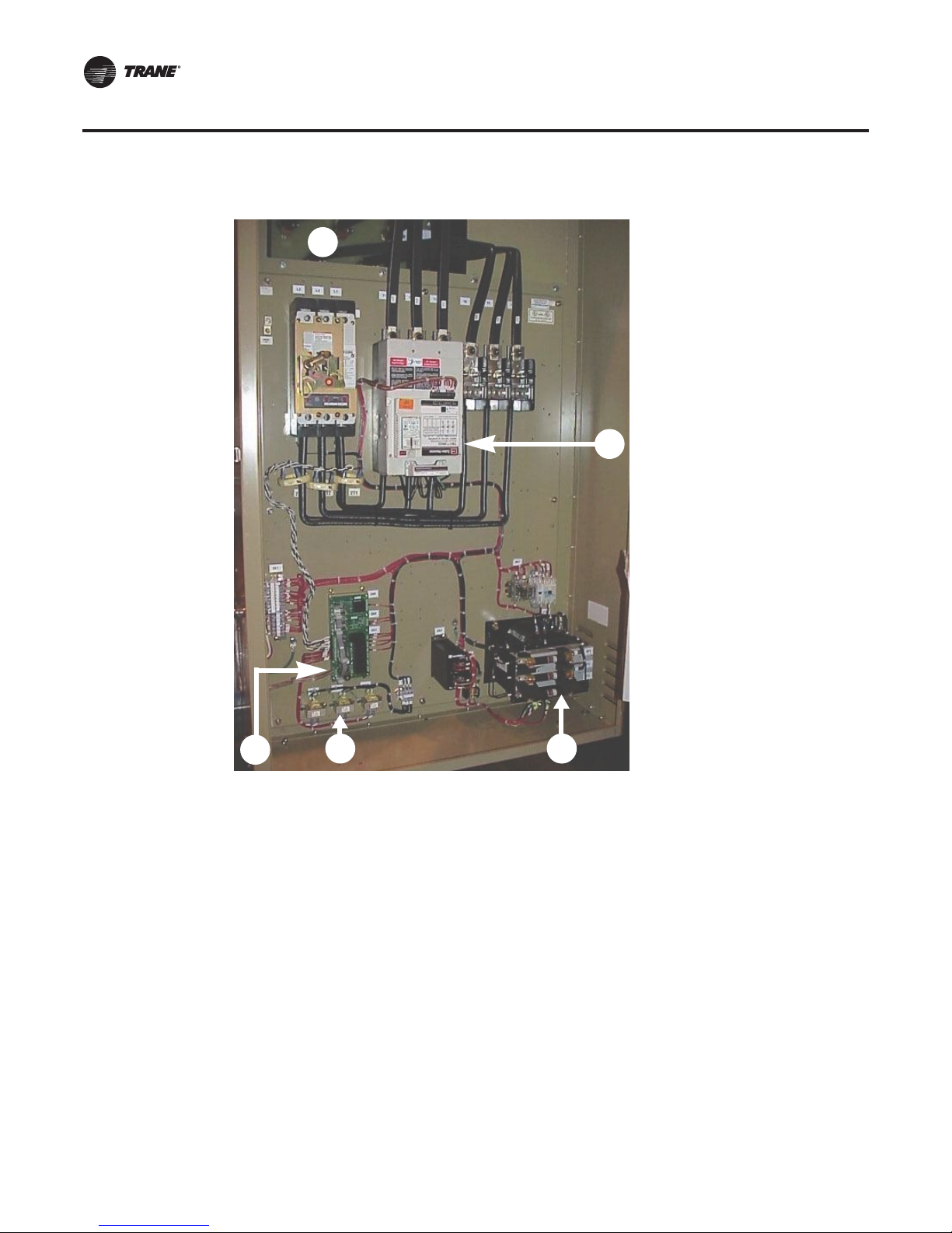
Figure 18. Trane AFD
1
2
4
• The AFD is rated by output current and is limited to a maximum of 100-percent continuous RLA
(rated-load amps) by theTrane
results in 100-percent torque generated by the motor.
®
chiller unit controller. A 100-percent output current capability
1. Pre-charge contactor
2. Inductor (behind the panel)
3. Adjustable-speed drive
5
(inverter)
4. Circuit breaker (standard)
5. Active rectifier
6. 3 kVA control-power
transformer
3
6
Features
The standard design features for the AFD include:
• NEMA 1, ventilated enclosure with a hinged door, tested to a short-circuit current rating of
65,000 amps.
• Padlock-able, door-mounted circuit breaker/shunt trip with an AIC rating of 65,000 amps.
• SCCR/AIC rating of 100,000 amps available as a design special.
• UL/CUL listed as a package.
• Simple, modular construction.
• 480/60/3 input power ±10 percent, with drive overload capability of 100 percent continuous to
150 percent for five seconds.
Note: For voltages other than 460/480 V, a transformer is currently needed to produce
460/480 V.
• Motor thermal overload protection 102 percent continuous, 108 percent for 60 seconds,
140 percent for 1.5 seconds.
• Minimum efficiency of 97 percent at rated load and 60 hertz.
• Soft-start, controlled acceleration, coast-to-stop.
• Adjustable frequency from 38 to 60 hertz.
• Control circuit voltages physically and electrically isolated from power circuit voltage.
• 150 percent instantaneous torque available for improved surge control.
• Output line-to-line and line-to-ground short-circuit protection.
• Ground fault protection (UL listed).
26 CTV-PRB004-EN
Page 27

Low-Voltage StarterTypes
Environmental specification
• 32°F to 104°F (0°C to 40°C) operating ambient temperature.
• Altitude to 3,300 feet (1,000 m), amperage derate of 1 percent per every 300 feet above
3,300 feet.
• Humidity, 95 percent non-condensing.
Dimensions
Typical dimensions for the unit-mounted Adaptive Frequency Drive are shown in Figure 19 and
Figure 20. Always consult the submittal drawings for as-built dimensions.
Figure 19. AFD dimensions
(405- and 608-amp design)
Figure 20. AFD dimensions
(900- and 1,210-amp design)
Door
swing
62"
Each door
swing
75"
32.5" & 24.5"
from front
of AFD
18"
is 31
"
from front
of AFD
26"
60"
98"
Motor-AFD mutual protection
The chiller unit-controller capabilities allow the control/configuration interface to, and the retrieval/
display of AFD-related data. AFD standard design features controlled through theTracer
AdaptiView™ include:
• Current limited to 100 percent.
• Motor overload protection.
• Motor over-temperature protection.
• Phase loss, phase reversal, and phase imbalance protection.
• Undervoltage and overvoltage protection.
• Output speed reference via IPC3 communication bus from the chiller controller to the AFD.
Digital data display
The following points are digitally displayed at the chiller controller:
• Output speed in hertz
• Output speed in rpm
• Input frequency
• Input/output line voltage
• Input/output kW
• Input/output current
• Average output current in percent RLA
• Load-side power factor
• AFD transistor temperature
• Fault
CTV-PRB004-EN 27
Page 28

Low-Voltage StarterTypes
Harmonics
Harmonics has become a frequently used term in the power quality arena. Of all the power quality
issues encountered today, harmonics is the least understood and most feared; unfortunately, this
has resulted in overstating the impact of harmonics.
Harmonics is not a “thing” but a way to define current or voltage distortion on a power line.
Harmonics can be directly linked to nonlinear loading of a power system. Nonlinear loads are
created by devices connected to a given power system that draw current from the power source
with a waveform that is not a pure sine wave.
All nonlinear loads, including variable-frequency drives, will create current and voltage distortion.
Typically harmonics is not an insurmountable issue when applying an AFD on a centrifugal chiller.
Harmonic attenuation
Harmonic attenuation is standard on the unit-mounted refrigerant-cooled AFDs and includes:
• Integrated active rectification control of the building AC power assures low line-generated
harmonics back to the user’s power grid.This results in less than 5 percent current harmonic
distortion (TDD) as measured at the AFD.
• Active input rectifier will regulate to a displacement power factor of 0.98 or better at full load
and a value of 0.96 at part load.
• Full motor voltage is applied regardless of the input voltage.
Note: TDD is a direct affect of variable-frequency drives and is a larger and more critical value than
the amount of total harmonic distortion (THD). As measured at the AFD, the amount ofTHD
will be less than theTDD.
IEEE 519
It is important to recognize that IEEE 519 relates to the entire system, not specifically to any one load
or product. IEEE 519 establishes requirements at the point of common coupling (PCC) where the
building connects to the utility system.The standard contains no specific requirements for the
internal electrical loads.
Even thoughTrane AFD-equipped chillers will attenuate their own harmonics, other nonlinear
loads on the same system could still create harmonic problems. In buildings where harmonics
might be a concern,Trane recommends conducting a power-distribution system analysis to
determine if there is a need to further attenuate harmonics at the system level.
Low Voltage—Remote-Mounted Adaptive Frequency Drive
Depending on the application,Trane also offers a remote free standing Adaptive Frequency Drive
(AFD).The remote AFD comes as a complete, free-standing package that includes the necessary
controls, control power and programming needed for operation. EachTrane Adaptive Frequency
Drive arrives completely programmed with all chiller control communication logic installed. Input
voltage options include 460, 480, 575, and 600 volts. Most of the low-voltage AFDs in the industry
are designed to work at 460/480 volts only. In HVAC applications were the voltage is 575/600, a
transformer would be need to apply an AFD. With theTrane remote AFD, a transformer would not
be needed, thereby eliminating the associated extra design time, space requirements, installation
costs and energy losses.
The design
The remoteAFD design is a voltage-source, pulse-width modulated (PWM) type. It consists of three
primary power sections.
Rectifier. Constructed of silicon controlled rectifiers (SCR), which convert the incoming utility AC
sine wave into DC voltage that will be stored in the DC Bus section
DC Bus Section. A capacitor bank that is used to store energy for use within the inverter section
28 CTV-PRB004-EN
Page 29

Low-Voltage StarterTypes
Inverter IGBTs. Use the pulse width modulation (pwM) method to convert the DC voltage from
the capacitor bank into a synthesized output AC voltage that controls both the voltage and
frequency applied to the motor
Figure 21. Front view, remote-mounted AFD
Features
The standard design features for the AFD include:
• Free standing NEMA 1, ventilated enclosure with a hinged door, tested to a short-circuit current
rating of 65,000 amps. Enclosure locking provisions are standard.
• Lockable, door-mounted circuit breaker/shunt trip with an AIC rating of 65,000.
• Amps, and enclosure short circuit rating of 65,000 amps standard.
• UL/CUL listed as a package.
• Simple, front access only design.
• 460/480/60/3 input power ±10 percent.
• 575/600/60/3 input power ±10 percent.
• Minimum efficiency of 97 percent at rated load and 60 hertz.
• Displacement power factor at 0.96 at all loads.
• Soft-start, linear acceleration, coast-to-stop.
• Adjustable frequency from 38 to 60 hertz.
• 150 percent instantaneous torque available for improved surge control.
• Output line-to-line and line-to-ground short-circuit protection.
• Ground fault protection (UL listed).
Optional Items
• NEMA 12 enclosure.
• 100,000 amp enclosure short-circuit current rating (SCCR) with 100,000-amp AIC circuit breaker
available as a design special.
CTV-PRB004-EN 29
Page 30

Low-Voltage StarterTypes
Environmental specification
• Operating temperature: 32°F to 104°F (0°C to 40°C).
• Storage temperature: -4°F to 149°F (-20°C to 65°C).
• Humidity: 95 percent non-condensing.
• Maximum elevation: 3280 ft (1000 m) rated output current.
• Derate 4 percent/3280 ft over rated altitudes up to 9840 ft (30 00 m).
Dimensions
Table 6 provides some basic reference dimensions and weights for the remote AFD. Always refer
and use theTrane submittals for actual dimensions.
Table 6. Remote AFD dimensions
460 Vac 575 Vac
Frame
D3/D4 150–350 394 150–400 356 48 24 86 1220
E2 450–600 649 450 400 56 24 90 1635
N/A N/A 500–650 560 64 24 90 1680
F3 650–750 791 750–1050 840 127 24 90 2885
950–1050 1031 N/A N/A 127 24 90 3185
F4 1150–1350 1360 1150–1550 1258 150 24 90 3720
Width (in.) Depth (in.) Height (in.) Weight (lb)Power (hp) Max. Amps Power (hp) Max. Amps
Digital data display
The following points are digitally displayed at the chiller controller:
• Frequency command
• Input line voltage
• Load-side amps
Harmonics
The remote AFD is a standard six pulse design. Therefore the harmonic level is ~35 percent total
demand distortionTDD as measured at the AFD input. If lower levels of attenuation are required,
upstream filtering would be required.
30 CTV-PRB004-EN
Page 31

Medium-Voltage Starter Types (2,300–6,600 Volts)
Table 7 shows the most common medium-voltage starter types available and compares inrush
current, torque, frequency of use, advantages and disadvantages, and typical acceleration time.
The inrush profiles are shown in Figure 22.
Which starter type is best?
One question often asked is: “Which is better, full voltage or reduced voltage?” Because mediumvoltage starters by nature use less current than low voltage, and therefore have significantly less
current inrush. Across-the-line medium-voltage starters are more commonly used; however, in
certain applications reduced voltage will be used to minimize starting strain on the electrical
system.
Table 7. Comparison of medium-voltage starters (2,300–6,600 volts)
Starter Type
(closed-transition)
Across-the-Line
(Full Voltage)
Primary Reactor
65% TAP
Autotransformer
65% TAP
AFD
Inrush
Current
% LRA
100 100 27%
65 42 49%
45 42 22%
<13
(<RLA)
Percent
Rated
Torque
Varies 2%
How
Often
Used Advantages Disadvantages
• Low cost
• Least complex
• Least maintenance
• Good compromise between
first cost and inrush current
reduction
• Almost equal reduction of
torque and inrush current
• Lowest inrush current
• Efficiency at part lift
• Power factor
Figure 22. Comparison of medium-voltage starting current
120
100
80
60
% LRA
40
• Draws highest inrush current
at startup
• More expensive than Acrossthe-Line
• Larger than Across-the-Line
• Most expensive
• Larger than Across-the-Line
• Very expensive
• Large and heavy
• Complex
Across-the-Line
Primary Reactor (65% tap)
Autotransformer (65% tap)
AFD
Typical
Acceleration
Time
(seconds)
3–5
5–12
5–12
5–12
20
0
01
Unit- or remote-mounted?
Unit-mounted medium-voltage starters can save on installed cost and space.They are tested in the
factory and are shipped on the chiller. Remote-mounted starters are sometimes bussed together
in various configurations as shown in “Multiple Starter Lineups (2,300–6,600 volts),” p. 61. Remote-
mounted starters fromTrane can have special NEMA options, whereas unit-mounted starters are
NEMA 1. All starters conform to ANSI/NEMA ICS-6 enclosure standards unless otherwise noted.
CTV-PRB004-EN 31
2345678910
Time (seconds)
Page 32

Medium-Voltage StarterTypes (2,300–6,600 Volts)
Other options for remote-mounted starters are available in the Enhanced Electrical Protection
Package (see “Industrial-Grade Starters,” p. 63.)
NEC 2005 changes for medium-voltage (2,300–6,600 volt) wire
NEC code for 2005 requires that medium-voltage cable is shielded. This affects the power wire
selection and connection provisions to the chiller, and between the chiller and starter when it is
remote mounted. When you use shielded cable, you must also use stress cones at the termination
points (motor terminal connection, remote starter, or unit-mounted starter connection). Stress
cones are composed of electrical shielding wrap and are typically 9–12 inches in length. Stress
cones are used to confine the dielectric field and reduce electrical stresses at the termination point.
®
Trane
that is shown in our as-built submittal drawings.The top hat is enclosed in the starter cabinet
during shipment and then reversed for field installation. Motor terminal boxes and remotemounted starters are designed to accommodate stress cones without an additional enclosure.
Refer to the appropriate submittals drawings to verify that the starter has sufficient connection
space for your requirements. For more information regarding the top hat, refer to “Unit-Mounted
StarterTop Hat—NEC 2005 Code Requirement,” p. 40.
unit-mounted medium-voltage starters now ship with a field-installed accessory “top hat”
Medium Voltage—Across-the-Line (2.3–6.6 kV)
Across-the-Line Starter (2,300–6,600 volts)
Figure 23, p. 33 shows a schematic for the most basic starter type; the across-the-line (X-Line)
starter, which is also known as a full-voltage starter.To illustrate a typical starting sequence using
a generic (non-Trane) schematic, refer to Figure 23, p. 33 and the starting sequence below.
Starting sequence
1. A “start” signal from the chiller controller energizes the pilot relay (PR).
2. The PR contacts close to energize the start/run contactor (1M).
3. The 1M contacts close to connect the compressor motor directly to the line.
32 CTV-PRB004-EN
Page 33
Medium-Voltage StarterTypes (2,300–6,600 Volts)
Figure 23. Simplified across-the-line wiring diagram
LINE
VOLTAGE
ACROSS-THE-LINE
STARTER WIRING
1M
1M
1M
F
CPT
F
START-
STOP
PR
OL
OL
OL
PR
1M
Figure 24. Unit-mounted, across-the-line starter dimensions
Top Hat
9.13"
MOTOR
27"
38"
Standard features
• Control-power transformer
• Primary and secondary current transformers (CTs)
• Potential transformers (PTs)
CTV-PRB004-EN 33
60"
26.2"
40"
20"
Page 34
Medium-Voltage StarterTypes (2,300–6,600 Volts)
• Grounding provisions
• Bolted line-power connections
• Bolted load-side connections for remote starters
• Standard motor protection
Environmental specification
• Designed, developed, and tested in accordance with UL 347
• NEMA 1 enclosure as standard
• Operation from sea level to 6,000 ft (1,829 m)
• Operating ambient temperature range 32°F to 104°F (0°C to 40°C)
• Relative humidity, non-condensing 5 percent to 95 percent
• Non-operating ambient temperature range -40°F to 158°F (-40°C to 70°C)
• Voltage utilization range ±10 percent
Dimensions
Typical dimensions for unit- and remote-mounted across-the-line starters are shown in Figure 24,
p. 33 and Figure 25, p. 34. Always consult the submittal drawings for as-built dimensions.
Figure 25. Remote-mounted XL
80"
30"
36"
34 CTV-PRB004-EN
Page 35
Medium-Voltage StarterTypes (2,300–6,600 Volts)
Figure 26. Unit-mounted, across-the-line, medium-voltage starter
1
1. Top-entry power
connection
2. Current-limited
power fuses
3. Vacuum
contactors
4. Low-voltage
section
5. Isolation switch
(provision for one
lock)
6. Control-power
transformer
2
5
6
Medium Voltage—Primary Reactor (2.3–6.6 kV)
Primary Reactor Starter (2,300–6,600 volts)
One of the most common starters in the industry is the primary reactor.To illustrate a typical
starting sequence using a generic (non-Trane) schematic, refer to Figure 27, p. 36 and the starting
sequence below.
Starting sequence
1. A “start” signal from the chiller controller energizes the pilot relay (PR).
2. The PR contacts close to energize the start contactor (1M).
3. The 1M contacts close to connect the compressor motor to the line with the motor in series with
the reactor
4. A time delay or current monitoring device initiates transition by energizing the run contactor
(2M).
.
3
4
CTV-PRB004-EN 35
Page 36
Medium-Voltage StarterTypes (2,300–6,600 Volts)
5. The 2M contacts close to bypass the reactor and connect the compressor motor directly to the
line.
Figure 27. Simplified primary reactor wiring diagram
LINE
VOLTAGE
PRIMARY REACTOR
80%
1M
OL
2M
65%
50%
1M
1M
F
CPT
F
START-
STOP
PR
TRANSITION
OL
OL
2M
2M
MOTOR
PR
1M
2M
Standard features
• Control-power transformer
• Primary and secondary current transformers (CTs)
• Potential transformers (PTs)
• Grounding provisions
• Bolted line-power connections
• Bolted load-side connections for remote starters
• Standard motor protection
Environmental specification
• Designed, developed, and tested in accordance with UL 347
• NEMA 1 enclosure as standard
• Operation from sea level to 6,000 ft (1,829 m)
• Operating ambient temperature range 32°F to 104°F (0°C to 40°C)
• Relative humidity, non-condensing 5% to 95%
• Non-operating ambient temperature range -40°F to 158°F (-40°C to 70°C)
• Voltage utilization range ±10%
Dimensions
Typical dimensions for remote-mounted primary reactor starters are shown in Figure 28, p. 37.
Unit-mounted primary reactor starter dimensions are shown in Figure 29, p. 37. Always consult the
submittal drawings for as-built dimensions.
36 CTV-PRB004-EN
Page 37
Medium-Voltage StarterTypes (2,300–6,600 Volts)
Figure 28. Remote-mounted, reduced-voltage starter dimensions
80"
30"
72"
Figure 29. Reduced-voltage, unit-mounted starter dimensions
Top Hat
9.13"
60"
40"
20"
38"
Reduced-Voltage
Section (mounted
on the condenser)
27"
26.2"
CTV-PRB004-EN 37
Page 38
Medium-Voltage StarterTypes (2,300–6,600 Volts)
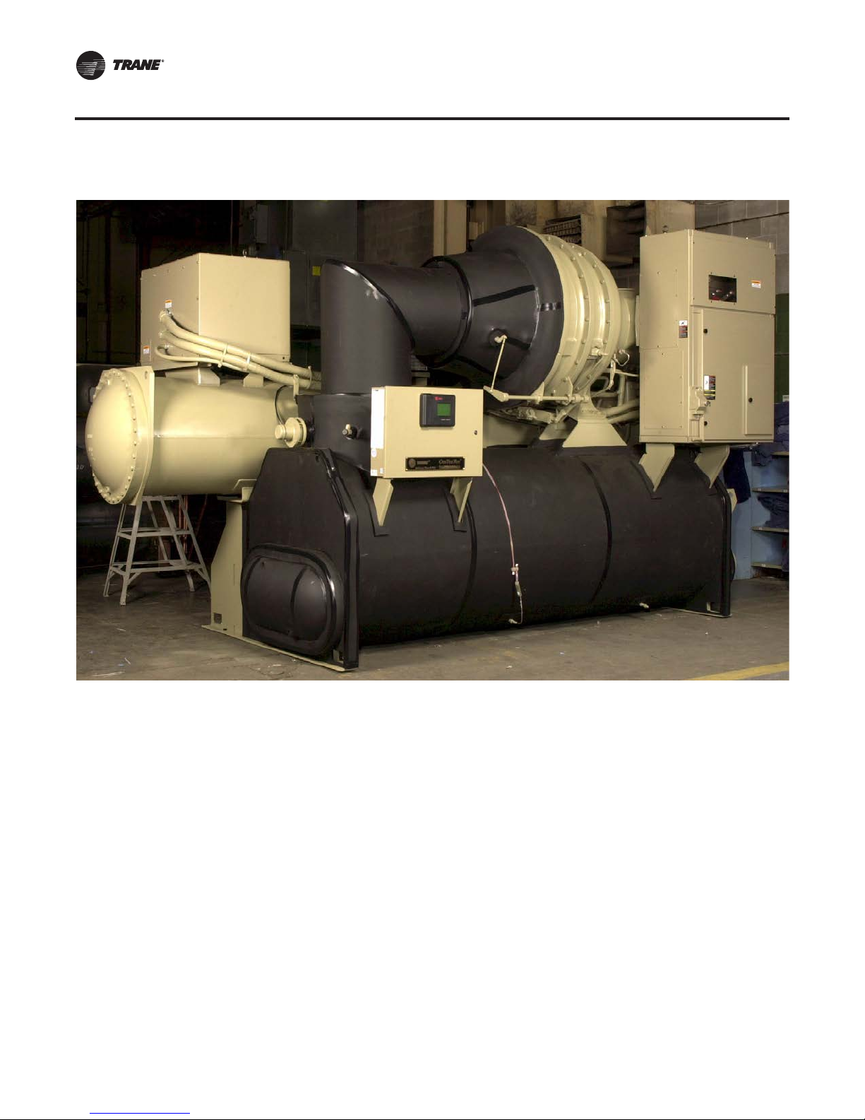
Figure 30. CenTraVac with a reduced-voltage autotransformer starter (CH530 unit controller)
Medium Voltage—Autotransformer (2.3–6.6 kV)
Autotransformer Starter (2,300–6,600 volts)
Another medium-voltage starter type is the autotransformer.To illustrate a typical starting
sequence using a generic (non-Trane) schematic, refer to Figure 31, p. 39 and the starting sequence
below.
Starting sequence
1. A “start” signal from the chiller controller energizes the pilot relay (PR).
2. The pilot relay contacts close to energize the shorting contactor (S).
3. The S contacts close to complete the autotransformer circuit.
4. An S interlock closes to energize the start contactor (1M).
5. The 1M contacts close to connect the compressor motor to the line with the motor in series with
autotransformer.
the
6. A time-delay relay or current-monitoring device initiates transition by energizing the transition
relay (T).
. TheT contacts open to de-energize the S contactor.
7
38 CTV-PRB004-EN
Page 39

Medium-Voltage StarterTypes (2,300–6,600 Volts)
8. The S contacts open to open the autotransformer circuit.
9. The autotransformer is now connected as a series reactor with the motor.
10. Now, a secondT interlock and a second S interlock both close to energize the run contactor (2M).
11. The 2M contacts close to bypass the transformer and connect the compressor motor directly
the line.
to
Figure 31. Simplified autotransformer wiring diagram
LINE
VOLTAGE
AUTO-TRANSFORMER
1M
1M
1M
F
CPT
F
START-
STOP
2M
T
PR
S
1M
TRANSITION
S
T
2M
OL
80%
S
S
100%
OL
2M
OL
50%
65%
PR
S
1M
T
2M
Standard features
• Control-power transformer
• Primary and secondary current transformers (CTs)
• Potential transformers (PTs)
• Grounding provisions
• Bolted line-power connections
• Bolted load-side connections for remote starters
• Standard motor protection
MOTOR
Environmental specification
• Designed, developed, and tested in accordance with UL 347
• NEMA 1 enclosure as standard
• Operation from sea level to 6,000 ft (1,829 m)
• Operating ambient temperature range 32°F to 104°F (0°C to 40°C)
• Relative humidity, non-condensing 5% to 95%
• Non-operating ambient temperature range -40°F to 158°F (-40°C to 70°C)
• Voltage utilization range ±10%
CTV-PRB004-EN 39
Page 40

Medium-Voltage StarterTypes (2,300–6,600 Volts)
Dimensions
Typical dimensions for both unit-mounted and remote-mounted autotransformer starters are the
same as the primary reactor starters shown in Figure 28, p. 37 and Figure 29, p. 37. A chiller with
a unit-mounted autotransformer starter is pictured in Figure 30, p. 38. Always consult the submittal
drawings for as-built dimensions.
Solid state medium-voltage starters
If you look at the medium-voltage chiller industry, there are three primary electro-mechanical
starter types commonly used: 1) Full Voltage (X-Line), 2) Primary Reactor, and 3) AutoTransformer.
Of these, X-Line and Primary Reactor make up a majority of the business.The balance is in
AutoTransformer and some solid state. Cost increases as you move from X-Line to
AutoTransformer, as does the relative complexity, and size.These starters are considered simple
to begin with in comparison to solid state starters; however, we always want to use the simplest
design if the performance (inrush level) meets the requirements of the application.This is why the
X-Line type is often used at this voltage, because the amps are generally low to begin with based
on the voltage class (i.e., 4,160 volts). Trane has shipped thousands of chillers and starters with
these electromechanical starter types. We know of no better way to offer the highest reliability,
lowest inrush, and still meet the 30-year life expectancy.
Over the years solid state starters have been available, however when the pros and cons are
evaluated, a traditional electro-mechanical is typically the best choice. Many claim that the solid
state is a “soft starter.” What does this really mean? For most, this means a ramped inrush profile
with no transients; however, because we are dealing with large induction motors, the ramp-up is
quick to enable the required torque.We think you need to look at the inrush magnitude, and when
you review the starter types, the primary reactor is very comparable to a solid state. However, the
cost of the primary reactor is typically less, it is simpler, more reliable, does not have harmonic
aspects to consider, and is easier to service and maintain. In the end, the decision is up to the
customer.
Unit-Mounted Starter Top Hat—NEC 2005 Code Requirement
As outlined in “Unit-Mounted StarterTop Hat—NEC 2005 Code Requirement,” p. 40, NEC 2005
code requirements specify the use of shielded cables and stress cones for medium-voltage wiring.
ForTrane
Medium voltage only (Enhanced Electrical Protection Package option),” p. 66) a supplementary
enclosure, or top hat, is shipped in the starter cabinet in order to fully enclose the incoming wire
and stress cones terminated at the starter.The top hat is shipped inverted in the starter cabinet to
avoid damage and must be properly configured in the field. The unit-mounted top hat is shown in
Figure 32, p. 41.
®
unit-mounted medium-voltage starters (and “SMP, Supplemental Motor Protection—
40 CTV-PRB004-EN
Page 41

Figure 32. Top Hat placement for shipment and installation
Sheet Metal “Top Hat” Section
(allows space for shielded cable/stress cones—field provided)
Medium-Voltage StarterTypes (2,300–6,600 Volts)
Stowed for Shipment Installed for Stress Cones
CTV-PRB004-EN 41
Page 42

Medium-Voltage StarterTypes (2,300–6,600 Volts)
Medium Voltage—Remote-Mounted Adaptive Frequency Drive
TheTrane AFD is a remote-mounted air-cooled, microprocessor based pulse width modulation
PWM design.The AFD use a “direct to drive” design that connects the power supply directly to the
medium voltage drive with out the use of an isolation transformer.The AFD is a current source
inverter that uses Symmetrical Gate Commutated Thyristors (SGCTs) power semi-conductor
switches in both the rectifier and inverter sections.The active front end rectifier and common mode
choke blocks any common mode voltages, smooths the DC current, and mitigates the motor neutral
to ground voltage. Because there is no negligible common mode voltages and currents, no special
compressor bearing provisions are required.The design does not generate dv/dt or reflected wave
voltage that can stress the motors. As a result, standard duty medium voltage motors can be used
with the AFD.
The AFD includes a line starter contactor and current limiting power fuses and a lockable non-load
break isolation switch as standard.The fuses are installed via fuse clips and can be replaced without
special tools. An integral common mode choke with iron core eliminates the need for semiconductor fuses which reduce nuisance trips. The AFD ships as a single, free-standing enclosure
(with a small exception of small top hat sections), wired, and tested to the job site.
Figure 33. Front view, medium voltage remote-mounted AFD
Remote AFD Design Features
• NEMA 1 ventilated, gasketed enclosure with hinged doors.
• Design access from the front only.The patented PowerCage inverter and rectifier module
allows easy access to main power components without the use of special hardware. Power
switch components are replaceable without removal of the entire power module.
• Paint—All exterior metal parts are painted with hybrid epoxy powder paint ANSI 49 medium
grey.The low voltage section is color coded black for safety.
• The entire package is UL/CUL listed.
Other AFD features include:
• Simple modular design.
• Compact, light weight design.
• Designed for minimum availability of 99.9 percent.
• Typical mean time between failure is 180,000 hours.
• Minimum predicted life expectancy is 20 years.
• The AFD is rated for the nominal chiller voltage ±10 percent.
42 CTV-PRB004-EN
Page 43

Medium-Voltage StarterTypes (2,300–6,600 Volts)
• Displacement power factor is 0.96 at all loads.
• Efficiency is 97.7 percent at rated load, 60 Hz.
• Soft-start; linear acceleration; coast to stop.
• All control circuit voltages are physically and electrically isolated from the power circuit
voltage.
• 110 percent instantaneous torque available for improved surge control.
• Output line-to-line and line-to-ground short circuit protection.
• Input protection via surge arrestors.
• Kirk key for interlocking the system which prevents unsafe access to doors.
• General AFD protection—The AFD includes a comprehensive set of protection features
segmented into the following three categories: 1) Line side level, 2) System level, and 3) Load
side level. For more information, refer to the Installation, Operation, and Maintenance manual.
• Near sinusoidal voltage and current waveforms to the motor at all speeds and loads. Output
currentTHD is less than 5 percent.
• The control power monitoring system monitors all power.
• Power switch device diagnostics detect and protect against device short, over or under gate
voltage loss, of gating, loss of diagnostic feedback, heat sink temperature feedback as well as
overload monitoring and protection.
• The drive system shall provide controlled speed over the range from 38 to 60 Hz.
• The AFD has a “normal duty” rating of 100 percent continuous current with a short time duty
rating of 110 percent overload for one minute, once every 10 minutes.
Chiller Unit Control Features for the AFD
The chiller unit control panel capabilities provide for the control/configuration interface to—and the
retrieval/display of—AFD-related data. AFD standard design features controlled through Tracer
AdaptiView include:
• Current limited to 100 percent at start, no inrush, true soft start
• Motor overload protection
• AFD over temperature protection
• Phase loss, phase reversal, and phase imbalance protection
• Overvoltage and undervoltage protection
Digitally-displayed AFD parameters on the AdaptiView panel: output speed in hertz, output speed
in rpm, input frequency, input/output voltage, input/output kW, output/load amps, average input
current, average current in % RLA, load power factor, fault, AFD temperature
In addition, on the AFD enclosure there is a 16-line, 40-character LCD display that can be utilized
by operators as needed. It includes a full comprehensive list of AFD performance parameters. refer
to the Installation, Operation, and Maintenance manual and the AFD manufacturer’s
documentation.
The AFD is designed for top entry line power and top or bottom load power exit.The power cable
connections are bolted type. Lugs are not provided. Use copper conductors only for terminal
connections. Failure to do so may cause corrosion or overheating, and AFD damage.
Environmental Ratings
• -40°F (-40°C) to 158°F (70°C) storage ambient temperature range.
• 32°F (0°C) to 104°F (40°C) operating ambient temperature range.
• Altitude to 3280 ft (1000 m), amperage derate output current above rated altitude up to 9840 ft
(3000 m).
• Humidity, 95 percent non-condensing.
Design Notes
The AFD should be located within 150 ft of the chiller. If this distance must be exceeded due to
application requirements, contact your localTrane representative.
CTV-PRB004-EN 43
Page 44

Medium-Voltage StarterTypes (2,300–6,600 Volts)
The AFD is designed for a maximum operating temperature of 104°F. However, optimal operation
and design life will be experienced if the ambient temperatures are kept well below this maximum.
The maximum AFD heat rejection is listed on the AFD submittal drawing in this package. Additional
equipment room cooling provisions may be required.
For all remote medium voltage AFDs, note that 4 kVA at 120-volt control power must be provided
to the chiller control panel, and this is customer supplied. Refer to the wiring diagrams in the
submittal package.
On some larger Frame B AFDs, note that the AFD itself requires a separate 8 kVA at 480-volt power
supply.This is in addition to the main power supply voltage.
Installation Notes
The AFD ships as a single enclosure, except for some “top hat” enclosures.These top hat sections
must be field installed. Refer to the AFD drawings for more information.
It is suggested that the AFD be placed on a housekeeping pad; anchoring the AFD to the ground
is not a manufacturer’s requirement. Consult local codes.
Refer to the AFD installation, operation, and maintenance manual, AFDJ-SVU01A-EN (Installation,
Operation, and Maintenance: Remote-Mounted Medium Voltage Air-Cooled Adaptive Frequency
Drive withTracer AdaptiView Control), or the most recent revision, for more detailed information
on AFD installation, operation and maintenance requirements.
Dimensions
See the specific submittals for the application. In general, for the the 4,160-volt class, the geometry
is as follows for the two frame sizes:
A Frame. RLA from 61–140 amps nominal at 4,160 V
94” wide X 40” deep X 105” high
B Frame. RLA from 160–250 amps nominal at 4,160 V
182” wide X 40” deep X 105” high
Digital data display
The following points are digitally displayed at the chiller controller:
• Output speed in hertz
• Output speed in rpm
• Input frequency
• Input/output voltage
• Input/output kW, load side amps
• Average output current in % RLA
• Average input current
• Load side power factor
• AFD temperature
• Fault
Harmonics
• Harmonic currents on the line side—Harmonics are minimized through the use of a common
mode choke and active rectifier.The AFD will meet a current harmonic distortion level of
5 percent or less in total demand distortionTDD as measured at the input to the AFD.
44 CTV-PRB004-EN
Page 45

Medium-Voltage Starter Types (10,000–13,800 Volts)
Table 7, p. 31, shows the available medium-voltage starter types for 10,000–13,800 volts.These are
identical in nature to their 2,300–6,600-volt counterparts in terms of inrush current, starting torque,
and their inherent advantages/disadvantages. Enclosure sizes are larger due to incoming line
provisions, internal components, and electrical shielding.These starters are available in remotemounted options only due to electrical restrictions associated with these higher voltages.
Note: UL certification of these starters is not available due to AC voltage ranges exceeding
7,200 volts as specified in UL Standard 347.This includes all chiller starter manufacturers
selling 10–13.8 kV refrigeration equipment. Low-voltage sections of the starters are UL rated
as applicable.
Which starter type is best?
In terms of starting torque and inrush current, these starters share the same advantages and
disadvantages similar to the 2,300–6,600-volt starters.The major difference for 10–13.8 kV starters
is the increased floor space required. If PFCCs are required, the dimensions will further increase
because the capacitors require their own separate enclosure. All starters are NEMA 1 rated as
standard and conform to ANSI/NEMA ICS-6 enclosure standards unless otherwise noted.
Medium Voltage—Across-the-Line (10–13.8 kV)
Across-the-Line Starter (10,000–13,800 volts)
Starting sequence
Refer to the across-the-line starting sequence (“Starting sequence,” p. 32).
Standard features
• 4 kVA control-power transformer
• Primary and secondary current transformers (CTs)
• Potential transformers (PTs)
• Grounding provisions
• Bolted line-power connections
• Bolted load-side connections for remote starters
• Standard motor protection
Dimensions
Typical dimensions for a remote-mounted across-the-line starter are shown in Figure 34, p. 46.
PFCCs, if required, are housed in a 36-inch wide auxiliary cabinet (not shown). Always consult the
submittal drawings for as-built dimensions.
Environmental specification
• Designed, developed and tested in accordance with IEC 60470, 62271-200
• NEMA 1 enclosure as standard
• Operation from sea level to 6,000 ft (1,829 m)
• Operating ambient temperature range 32°F to 104°F (0°C to 40°C)
• Relative humidity, non-condensing 5 percent to 95 percent
• Non-operating ambient temperature range -40°F to 158°F (-40°C to 70°C)
• Voltage utilization range ±10 percent
CTV-PRB004-EN 45
Page 46

Medium-Voltage StarterTypes (10,000–13,800 Volts)
Figure 34. Remote-mounted, across-the-line dimensions
MAIN BUS
INCOMING
LINE
LOW-VOLTAGE
SECTION
95"
36"
60"
Figure 35. Remote-mounted, 11-kV, across-the-line starter
1
1. Current-limiting power fuses
2. Isolation switch (provision for one
lock)
3. Control-power transformer
4. Vacuum contactors
3
46 CTV-PRB004-EN
2
4
Page 47

Medium-Voltage StarterTypes (10,000–13,800 Volts)
Medium Voltage—Primary Reactor (10–13.8 kV)
Primary Reactor Starter (10,000–13,800 volts)
Starting sequence
1. Refer to the primary reactor starting sequence (“Starting sequence,” p. 35).
Standard features
• 4 kVA control-power transformer
• Primary and secondary current transformers (CTs)
• Potential transformers (PTs)
• Grounding provisions
• Bolted line-power connections
• Bolted load-side connections for remote starters
• Standard motor protection
Dimensions
Typical dimensions for remote-mounted primary reactor starters are shown in Figure 36, p. 47.
PFCCs, if required, are housed in a 36-inch wide auxiliary cabinet (not shown). Always consult the
submittal drawings for as-built dimensions.
Environmental specification
• Designed, developed and tested in accordance with IEC 60470, 62271-200
• NEMA 1 enclosure as standard
• Operation from sea level to 6,000 ft (1,829 m)
• Operating ambient temperature range 32°F to 104°F (0°C to 40°C)
• Relative humidity, non-condensing 5 percent to 95 percent
• Non-operating ambient temperature range -40°F to 158°F (-40°C to 70°C)
• Voltage utilization range ±10 percent
Figure 36. Remote-mounted, primary reactor dimensions
MAIN BUS
INCOMING
LINE
LOW-VOLTAGE
SECTION
132"
CTV-PRB004-EN 47
MAIN BUS
MAIN BUS
96"
36"
Page 48
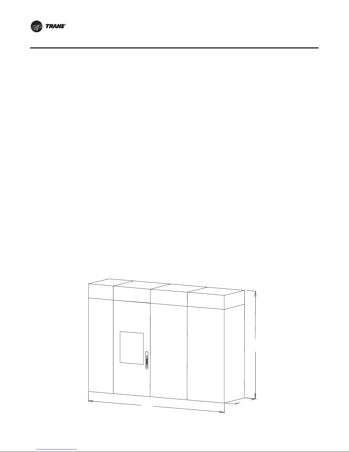
Medium-Voltage StarterTypes (10,000–13,800 Volts)
Medium Voltage—Autotransformer (10–13.8 kV)
Autotransformer Starter (10,000–13,800 volts)
Starting sequence
Refer to the autotransformer starting sequence (“Starting sequence,” p. 38).
Standard features
• 4 kVA control-power transformer
• Primary and secondary current transformers (CTs)
• Potential transformers (PTs)
• Grounding provisions
• Bolted line-power connections
• Bolted load-side connections for remote starters
• Standard motor protection
Dimensions
Typical dimensions for remote-mounted autotransformer starters are shown in Figure 37, p. 48.
PFCCs, if required, are housed in a 36-inch wide auxiliary cabinet (not shown). Always consult the
submittal drawings for as-built dimensions.
Environmental specification
• Designed, developed and tested in accordance with IEC 60470, 62271-200
• NEMA 1 enclosure as standard
• Operation from sea level to 6,000 ft (1,829 m)
• Operating ambient temperature range 32°F to 104°F (0°C to 40°C)
• Relative humidity, non-condensing 5 percent to 95 percent
• Non-operating ambient temperature range -40°F to 158°F (-40°C to 70°C)
• Voltage utilization range ±10 percent
Figure 37. Remote-mounted, autotransformer dimensions
MAIN BUS
INCOMING
LINE
LOW-VOLTAGE
SECTION
132"
48 CTV-PRB004-EN
MAIN BUS
MAIN BUS
96"
36"
Page 49

Electrical System—Ratings
“Normal” and “overload” conditions … “fault current” … “interrupt” versus “short-circuit”
ratings” … “current-limiting.” Knowing what these terms mean and applying them correctly are
fundamental to designing safe, reliable electrical distribution systems.This is especially true in
light of more stringent code enforcement and the current design trend to deliver energy savings
by selecting low-impedance transformers: How does this influence safety? Lower transformer
impedances result in higher short-circuit currents.
Simply choosing a circuit breaker with a high-interrupt rating won't assure adequate protection
under short-circuit conditions. An “ounce of prevention” helps avoid the code official’s “red tag”
at the next system startup. The following section reviews the meaning of terms, defines some of
the issues related specifically to HVAC motor starter applications, and identifies practical effective
solutions.
Normal operation
“Normal operation” describes the full-load (or rated) conditions of each system component. For
motors, it includes the amps initially drawn at startup, i.e. inrush current, as well as the full- or ratedload amps drawn while running.The magnitude of inrush current for a particular application
depends on the motor, voltage, and type of starter used.
Normal operating conditions determine wire and transformer sizing.They are also used in
conjunction with “fault conditions” to select overcurrent protection devices such as circuit
breakers and fuses. Rating factors are applied, based on the type and number of connected loads,
to assure that the devices selected adequately protect the motor as it starts and while it is running.
The size of the interconnecting wires between the transformer and starter reflects the type and
rated amperage draw of the load, i.e. the chiller motor. Sizing the wires on this basis assures that
they can carry the inrush current at startup without overheating.
Available Fault Current (AFC)
Refer to Figure 39, p. 52, for the reference points or label locations of each rating. AFC is the
calculated potential short-circuit current at a point just upstream of the starter. It is calculated by
the electrical engineer and is a function of the electrical distribution system—including the
transformers.
Imagine a wrench inadvertently left in a starter after servicing. Touching two power phases, it
completes the circuit between them when the panel is energized. This results in a potentially
dangerous situation, or “fault condition,” caused by the low-impedance phase-to-phase or phaseto-ground connection … a “short circuit”.
Fault current, also called “short-circuit current” (I
a short. It passes through all components in the affected circuit. Fault current is generally very large
and, therefore, hazardous. Only the combined impedance of the object responsible for the short,
the wiring, and the transformer limits the fault current.
One objective of electrical distribution system design is to minimize the effect of a fault, i.e. its
extent and duration, on the uninterrupted part of the system. Coordinating the sizes of circuit
breakers and fuses assures that these devices isolate only the affected circuits. Put simply, it
prevents a short at one location from shutting down power to the entire building.
Calculating the magnitude of short-circuit current is a prerequisite to selecting the appropriate
breakers and fuses. If the distance between the transformer and starter is short, the calculation can
be simplified by ignoring the impedance of the interconnecting wiring… a simplification that errs
on the side of safety. One can also assume that the source of the fault has zero impedance, i.e. a
“bolted” short. Given these assumptions, only the transformer impedance remains. (Impedance
upstream of the transformer is usually negligible.)
Suppose a 1,500-kVA, 480-volt transformer has impedance of 5.75 percent. With this value, use the
equation below to determine how much fault current a short circuit will produce.The resulting I
shows that a short would force the wiring to carry more than 30,000 amps when it was designed
to handle only 400 amps!
), describes the amount of current flow during
sc
sc
CTV-PRB004-EN 49
Page 50

Electrical System—Ratings
I
I
Short-circuit current is often two orders of magnitude greater than normal operating current.
Unless a circuit breaker or fuse successfully interrupts the fault, this enormous amperage rapidly
heats components to very high temperatures that destroy insulation, melt metal, start fires … even
cause an explosion if arcing occurs or components disintegrate.The inherent likelihood of severe
equipment and property damage, as well as the risk of personal injury or death, underscores the
importance of sufficient electrical-distribution system protection.
1,500 kVA x 1000/k
=
SC
480 V x 1.73 x 0.0575
= 31,400 amps
SC
Ampere-Interrupt Current (AIC)
Determined under standard conditions, the “interrupt rating” specifies the maximum amount of
current a protective device can cut off safely … i.e. without harm to personnel or resulting damage
to equipment, the premises or the device itself. For example, a circuit breaker that trips “safely”
successfully interrupts the fault, can be reset, and will function properly afterward.
A common misconception is, “An overcurrent protection device with a comparatively highinterrupt rating limits current to other components.” Not so, not unless it is also a true currentlimiting device. Even though the device successfully breaks the circuit, all components in the circuit
will be exposed to the full magnitude of fault current (as well as the severe thermal and magnetic
stresses that accompany it) for the small amount time it takes the device to respond.
Short-Circuit Current Rating (SCCR)
Sometimes referred to as the short-circuit withstand rating (SCWR), the short-circuit current rating
(SCCR) is probably the most critical rating for short-circuit protection that the electrical engineer
must obtain from the starter supplier.The term “withstand” is no longer used by NEC and UL.The
entire assembled starter enclosure has an SCCR.
The short-circuit current rating is the maximum fault current that the starter withstood during
testing by Underwriters Laboratories, Inc. UL 508 defines the short-circuit test methods and
parameters for HVAC equipment, and therefore the SCCR is mainly a low-voltage issue. Essentially,
the test simulates an actual fault current in the starter enclosure, e.g. 50,000 amps. If the doors blow
open or if the starter emits debris, the enclosure fails the test. For those that pass, it is “acceptable,”
and even probable, that the internal components will be damaged beyond repair. Given the
destructiveness and expense of this test, it is not surprising that most manufacturers prefer not to
pursue higher-than-normal short-circuit current ratings for their equipment unless there is a
documented need.
Recall that when a fault occurs, all components in the circuit experience the brunt of the short circuit
until it is interrupted.Therefore, it is important to assure that all components “at risk” can
withstand a fault condition without causing personal injury or damaging the surroundings.The
National Electric Code (NEC) states this requirement in Section 110.10, “Circuit Impedance and
Other Characteristics”:
The overcurrent protective devices, the total impedance, the component short-circuit
[withstand] ratings, and other characteristics of the protected circuit shall be selected and
coordinated to permit the used circuit protective devices to clear a fault without extensive
damage to the circuit’s electrical components.This fault is assumed to be either between two
or more of the circuit conductors, or between any circuit conductor and the grounding
conductor or enclosing metal raceway. Listed products applied in accordance with their listing
shall be considered to meet the requirements of this section.
Commentary in the 1996 National Electrical Code™ Handbook further explains Section 110.10:
50 CTV-PRB004-EN
Page 51
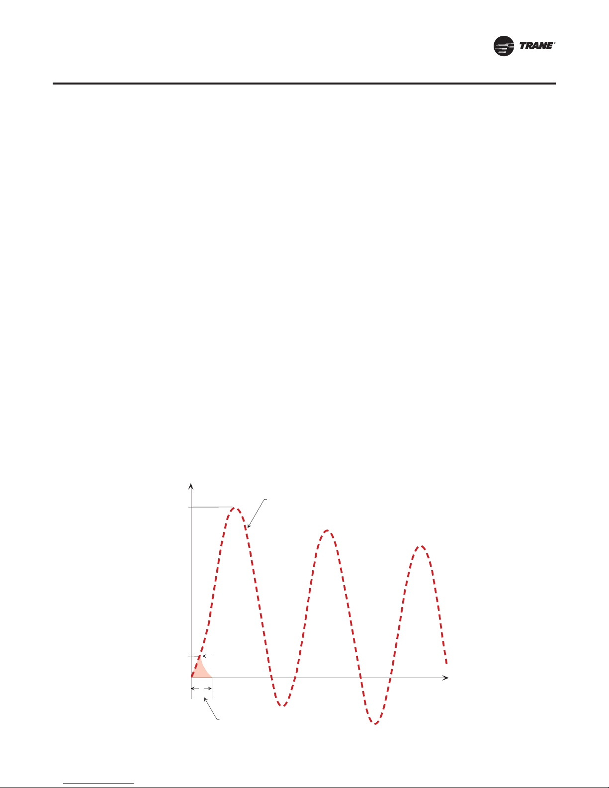
Electrical System—Ratings
Overcurrent protective devices (such as fuses and circuit breakers) should be selected to ensure
that the short-circuit withstand rating of the system components will not be exceeded should
a short circuit or high-level ground fault occur.
System components include wire, bus structures, switching, protection and disconnect
devices, distribution equipment, etc., all of which have limited short-circuit current ratings and
would be damaged or destroyed if these short-circuit current ratings are exceeded. Merely
providing overcurrent protective devices with sufficient interrupting ratings will not ensure
adequate short-circuit protection for the system components. When the available short-circuit
current exceeds the withstand rating of an electrical component, the overcurrent protective
device must limit the let-through energy to within the rating of that electrical component.
To comply with this section of NEC without additional current-limiting devices, most chiller-motor
configurations will require a short-circuit current rating well above UL’s standard ratings.
Let-Through Current (LTC)
This is the fault current that passes through the circuit breaker before the circuit breaker trip
element has time to respond, typically equal to or less than the available fault current and lasting
three-quarter of an electrical cycle.
Current limiting
All components and wiring in an electrical distribution system offer some degree of resistance.
Under normal conditions, the heat produced when current flows against this resistance readily
dissipates to the surroundings; however, the enormous current generated during a short circuit
produces damaging heat at a much faster rate than can be safely dissipated. Interrupt the current
and you stop adding heat to the system. As Figure 38 suggests, time is a critical determinant of the
amount of heat (energy) added. An electrical short that lasts three cycles, for example, adds six
times the energy of an electrical short lasting just one-half cycle. It is in this sense that all circuit
breakers and fuses “limit” current.
Figure 38 also shows the effect of a current-limiting device. To be truly current limiting, the
interrupting device must open the circuit within one-quarter cycle (1/240 second), i.e. before the
fault current peaks.
Figure 38. Illustration of short-circuit current
100,000
Current
Peak Fuse
10,000
0
CTV-PRB004-EN 51
“Let-Thru”
Current
t
c
Total Fuse Clearing Time
Prospective available short-circuit current
that would flow when a fuse is not used.
Time
Page 52
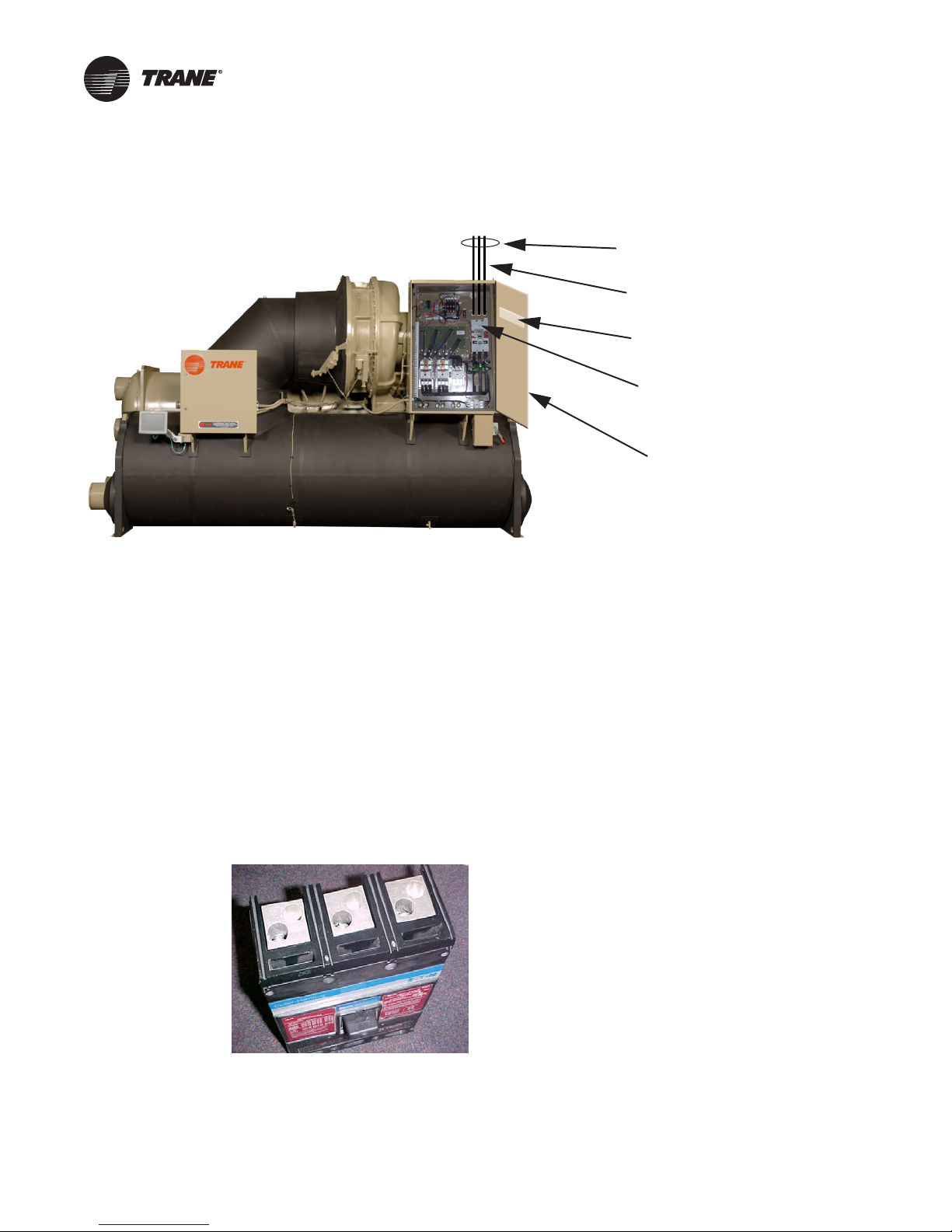
Electrical System—Design Guidelines
Figure 39. Electrical rating label locations
There are three functions that electrical engineers must address when designing electrical systems
that include chiller motors and the associated starters:
1. Means of disconnect
2. Means for short circuit interruption
3. Making sure that the starter enclosure has an adequate short-circuit current rating for the
available fault
current (low voltage) or properly sized fuses (medium voltage)
AFC—available fault current
Three-phase line power
SCCR—starter short-circuit
current rating
AIC—circuit breaker
ampere-interrupting rating
Starter door
Disconnect Means
Low-voltage disconnect
Low-voltage starters from Trane do not have a disconnect means as standard. The standard line
power connection is a terminal block (i.e., main lug only) connection. An optional non-fused
disconnect switch, in a molded case as shown in Figure 40, can be installed. These non-fused
disconnect switches typically have locking provisions to allow the switch to be locked open; often
with up to three different padlocks.
Figure 40. Non-fused disconnect
A non-fused disconnect switch is used when servicing the chiller to protect someone from personal
injury, and it can also be used as a load-break switch in an emergency. Since the disconnect switch
is a non-fused device, current limiting protection must be installed upstream of the chiller by
others.
52 CTV-PRB004-EN
Page 53
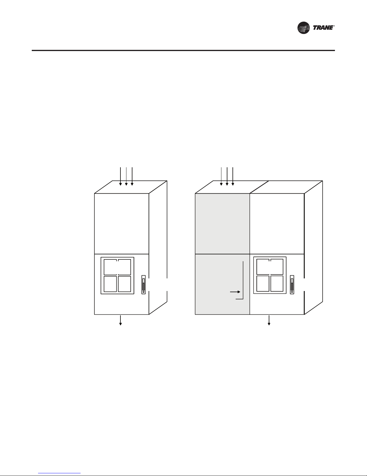
Electrical System—Design Guidelines
Medium-voltage disconnect
All medium-voltage starters have an isolation switch as standard.This switch is a non-load-break
switch that is not designed to be opened under load, i.e. while the chiller is operating. All mediumvoltage starters have a mechanical interlock to prevent opening the isolation switch while the main
contactor is closed and the compressor is running.
In order to open the medium-voltage compartment door,the compressor must be turned off before
the isolation switch can be opened. Then the isolation switch stabs can be separated from the
medium-voltage bus. Baffles slide over the stab slots and the medium-voltage bus is completely
isolated behind shielding panels. Now the medium-voltage compartment door can be opened
safely. After servicing, the medium-voltage compartment door must be secured before the
isolation switch can be closed.
Figure 41. Isolation switch Figure 42. Load-break switch
incoming line power
incoming line power
load-break
switch section
Low
Volts
isolation
switch
outgoing load power
If there is a requirement to be able to open the circuit while under load, a load-break disconnect
switch may be furnished as a special option on medium-voltage starters.The load-break switch is
mounted in an additional section of the starter-cabinet assembly. See Figure 41 and Figure 42 for
a comparison of the two options. A switch spring is loaded, or “charged,” as the handle is moved.
When spring pressure is sufficient, a device releases the switch mechanism.The spring loading
provides a rapid, positive opening and closing of the contacts.
Note: Medium-voltage circuit breakers are not available throughTrane.
load-break
switch
X-Line starter
Low
Volts
isolation
switch
outgoing load power
Short-Circuit Interruption
Low-voltage short-circuit interruption
When a circuit breaker is specified, it serves both as the short-circuit interrupt protector and the
disconnect switch. Unlike the non-fused disconnect, a circuit breaker does have an interrupting
rating. Because a circuit breaker is constructed to safely interrupt the high level of current caused
CTV-PRB004-EN 53
Page 54

Electrical System—Design Guidelines
by a short circuit (fault current), it may be opened safely at any time. A low-voltagestarter door may
be opened only if the circuit breaker is in the “off” or open position.
Circuit breakers of various interrupt ratings are offered as options.The interrupting capacity of a
circuit breaker must also be considered. An analysis of an installation is usually done by the
electrical engineer to calculate the maximum available fault current (AFC) that could be delivered
if a short circuit occurred.
When a low-voltage starter is ordered with a circuit breaker, the starter manufacturer furnishes a
standard circuit breaker sized at approximately 125 percent of compressor RLA or larger.The trip
current of a circuit breaker is adjustable so that it will not trip during starting and acceleration, but
will trip instantaneously (typically within one cycle) if a short circuit occurs.
Short-Circuit Current Rating (SCCR)
The disconnect means and the short-circuit protection discussed above are either supplied and
installed by the customer upstream of the starter or they can be supplied as options with theTrane
starter. However, the starter’s SCCR must be communicated to the electrical engineer early in the
project to ensure that the starter short-circuit current rating will meet the requirements. If the SCCR
is not high enough, the electrical engineer will have to look for solutions upstream of the starter.
Each low-voltageTrane
size of the starter as well as the type of disconnect or circuit breaker included. See the appropriate
submittal drawings for the starter short-circuit current rating.
Note: Don’t confuse short-circuit current rating (SCCR) with silicone controlled rectifier (SCR)—
utilized in solid-state starters and AFDs.
®
starter or frequency drive has a short-circuit current rating, based on the
®
Medium-voltage short circuit interruption
All medium-voltage starters contain current-limiting fuses for short circuit protection.The currentlimiting fuses and isolation switch, which is furnished as standard, fulfill the request for a fused
disconnect. If you need more detail on the fuses for a particular starter contact CenTraVac Field
Sales Support.
It turns out that the starter short-circuit current rating is not an issue with medium-voltage starters.
BecauseTrane
and provided as standard, and the starter short-circuit current rating no longer applies. Mediumvoltage starters fromTrane have an interrupt rating based on the standard current-limiting fuses.
At 4,160 volts, the NEMA E2 fused-interrupt rating is 50,000 amperes or 400 MVA.
Medium voltage fuse coordination suggestions
Proper sizing of fuses and circuit breakers upstream of the starter is the responsibility of the
customer or the electrical engineer.
Power Circuit Requirements
Starter Applications
When applying a starter to a chiller motor on a specified power circuit, the power circuit has to meet
minimum criteria to allow for a successful chiller start without an immediate shutdown or safety
trip.This applies to utility power, local or smaller-scale facility power, and backup or peak-shaving
generator power.
The following are some considerations for motor starter power quality requirements:
• Size of the power circuit
• Source and/or total system impedance
• System regulation
• Inrush characteristics of the starter type
• Acceleration time
• Maximum voltage sag
• Maximum voltage swell
®
medium-voltage starters meet UL 347, current-limiting power fuses are required
54 CTV-PRB004-EN
Page 55

Electrical System—Design Guidelines
• Additional (non-chiller) loads on the power circuit
When evaluating a power system for a chiller-compressor motor with a specified starter type,
calculations must be done in order to size or “correct” the power circuit properly in order to
successfully start the motor and keep the motor-starter combination online during operation.
Table 9 and Table 10, p. 55 show specific starter characteristics and minimum power requirements.
Table 9. Sizing requirements
(a)
Percent
Rated
Torque
Inrush
Current
Starter Type Voltage Range
Wye-Delta 208–600 V 33 27 33
Solid-State 208–600 V ~45 27 33
X-Line 2.3–13.8 kV 100 6 100
Primary Reactor 2.3–13.8 kV 65 16 42
Autotransformer 2.3–13.8 kV 45 16 42
AFD 460–600 V <13 12 Varies
(a)The Chiller Controller Maximum Acceleration Time Setpoint is the maximum allowable acceleration time;
if the chiller has not started within this time, a diagnostic will be set.
% LRA
Chiller Controller
Maximum Acceleration
Time Setpoint (sec)
Table 10. Motor starter operational voltage range—during a start
Maximum
Line-to-Line
Starter Size Starter Description
155–606 amps Unit- and Remote-Mounted
607–1,316 amps Unit-Mounted
607–1,856 amps Remote-Mounted
185–1,120 amps Unit- and Remote-Mounted
180–960 amps Remote-Mounted,
961–1,600 amps Remote-Mounted,
155–1530 amps Unit- and Remote-Mounted
94, 187, 205/288 amps
(205 reduced voltage, 288
full voltage)
94, 187, 360 amps Remote-Mounted
94 amps Remote-Mounted
61–250 amps @ 4,160 V Remote Medium-Voltage AFD 25% 10%
Wye-Delta
Wye-Delta
Wye-Delta
Solid-State
High-Fault Solid-State
High-Fault Wye-Delta
Low Voltage AFD
(460–600 V)
Unit-Mounted
Medium Voltage
(2.3–6.6 kV)
Medium Voltage
(2.3–6.6 kV)
Medium Voltage
(10–13.8 kV)
RMS Voltage Sag
25% 15%
25% 15%
20% 15%
25% 15%
25% 15%
25% 15%
25% 10%
25%
(20% w/additional
protection)
25%
(20% w/additional
protection)
25%
(20% w/additional
protection)
Maximum
Line-to-Line
RMS Voltage Swell
15%
15%
15%
Note: The maximum allowable under/overvoltage during normal operation is ±10 percent.
CTV-PRB004-EN 55
Page 56

Electrical System–Power Wire Sizing
This section provides guidance for sizing the power conductors forTrane CenTraVac water chillers
including wiring from the distribution system to the starter, and wiring from the starter to the
compressor motor.The information provided does not constitute a design manual and does not
supersede local code requirements or National Electric Code (NEC) recommendations. Final wire
size selection must be verified by the Engineer of Record for the installation.
Wire size and count should be coordinated with the starter selection so the starter can be ordered
with the proper terminal lugs. The starter is shipped with standard lugs as shown on the as-built
submittals. Alternate lugs are often available and can be purchased locally. Standard lugs accept
a wide range of wire sizes, but not all possible combinations.
General wiring requirements
• When more than one lead per phase is used (paralleled conductors), the leads must be of the
same size and length so that they share the load equally. Paralleled conductors are only
permitted for wire sizes of 1/0 and larger.
• When two or more conduits are used, all three phases must be equally represented in each
conduit to
Specific requirements for distribution system to starter wiring
• Wiring to the starter must be copper. A discussion of why aluminum should not be used can
be found in the Glossary (“Aluminum conductors,” p. 73).
• Wiring to all starters must be in multiples of three.
Specific requirements for starter to motor wiring
• All wiring to the CenTraVac motor must be copper. The UL listing on the CenTraVac requires
copper conductors, and the terminal blocks on the motor studs are only compatible with copper
wire.
• Wiring to motors used with variable frequency drive, across-the-line, autotransformer, or
primary reactor
the procedure used for sizing supply wire from the distribution system to the starter.
• Wiring to motors used with wye-delta (also referred to as star-delta) or inside-the-delta solidstate star
are only applicable to the inside-the-delta solid-state starter designs offered for CenTraVac
chillers shipped since June 1999. All other solid-state starter designs should follow the acrossthe-line
• A minimum of three feet of flexible conduit is required at the connection to the motor junction
box
avoid overheating.
starters must be in multiples of three. Wire for these starters is sized following
ters must be in multiples of six.The solid-state starter wire sizing tables included here
sizing tables.
wire
to provide vibration isolation.
Wire size guidelines
The following information is based on the 2011 National Electric Code (NEC). Most local codes are
based on the NEC; however, local codes may vary from the NEC on specific details. Final wire size
selection must be verified by the Engineer of Record for the installation.
Various factors are involved in selecting the proper wire including amperage draw of the load, type
of load, voltage, temperature rating of the wire, number of conductors within a conduit, and
ambient temperature. In addition, the wires connecting the starter to the motor may need to be
sized differently than the wires that connect the distribution system to the starter.
Good circuit design also involves checking the voltage drop of the distribution circuit.The NEC does
not require this step, but does suggest that 3 percent voltage drop on a branch circuit feeder and
5 percent overall will provide “reasonable efficiency of operation”.
The NEC requires HVAC manufacturers to calculate and include “minimum supply circuit
conductor ampacity” (also referred to as Minimum Circuit Ampacity [MCA]) on the unit name plate
(section 440.4 [B]). MCA is equal to 1.25 times the RLA of the largest motor plus 100 percent of all
56 CTV-PRB004-EN
Page 57

Electrical System–PowerWire Sizing
other electrical loads. Branch circuit wires supplying the unit must have an ampacity greater than
the MCA.
Table 11, p. 58 through Table 16, p. 60 are based on the 2011 NEC conductor ampacities tables for
copper wire, run in conduit, in air, for several common wire types and configurations. Where
required by the NEC the values in the tables have been adjusted for more than three wires in a
conduit.
Table 11, p. 58 through Table 14, p. 59 are for 0–2000 V applications where the ambient
temperature around the conduit is between 78°F–86°F (26°C–30°C); Table 15, p. 60 and Table 16,
p. 60 are for 2,001 V–35 kV applications where the ambient temperature around the conduits is
104°F (40°C) or less. Installations with ambient temperatures outside these ranges require an
additional ampacity adjustment for proper wire selection.
The tables provide an easy way to estimate wire size. Enter the appropriate table, knowing the
nameplate MCA of the chiller; a table value greater than the MCA indicates a valid wire/conduit
selection (for the conditions described earlier in this section).
Example
The example chiller has a remote-mounted wye-delta starter and the nameplate indicates an RLA
of 300 and an MCA of 384 at 460 volts.
If 75°C conductors are used, the supply leads from the distribution system to the starter are sized
using Table 11, p. 58. Comparing the MCA to the table values indicates the conductors could be any
of the following combinations:
• one conduit containing three 600 MCM conductors
• one conduit containing six 250 MCM conductors
• two conduits containing three 3/0 conductors each, and so on
Because this is a wye-delta starter the leads from the starter to the motor are sized differently than
supply leads to the starter. If 75°C conductors are used the leads from the starter to the motor
the
are sized using Table 12, p. 58. Comparing the MCA to the table indicates the following
combinations are allowed:
• one conduit containing six 300 MCM conductors
• two conduits containing three 4/0 conductors each
• two conduits containing six 1/0 conductors each
Conductor ampacity tables
The wire selection tables (Table 11, p. 58 through Table 16, p. 60) may be used for estimating
conductor and conduit combinations that will support the amperage draw of CenTraVac chillers.
Wire sizes are given in units of AWG (American wire gauge) or kcmil (thousands of circular mils),
also referred to as MCM or KCM.
Find the appropriate table based on voltage, wire temperature rating, and where the wire will be
used. A table value greater than the nameplate MCA indicates a valid wire/conduit selection (for
the conditions described earlier in this section).Then check that the selected combination will fit
in the starter lugs by reviewing the starter submittal data. Final wire size selection must be
confirmed by the Engineer of Record for the installation.
CTV-PRB004-EN 57
Page 58

Electrical System–PowerWire Sizing
Table 11. MCA look-up table for 75°C copper conductors rated for 0–2,000 Volts
(a)
Note: Use this table to select supply leads for all starters, and motor leads for remote-mounted across-the-
line, primary reactor, autotransformer, and Adaptive Frequency Drives. Value in table must be larger
than the MCA to use the wire combination.
Wire Size
850
665
485
3 100
2 115
1 130
0 150 240 300 450 480 600 750 900
00 175 280 350 525 560 700 875 1050
000 200 320 400 600 640 800 1000 1200
0000 230 368 460 690 736 920 1150 1380
250 255 408 510 765 816 1020 1275 1530
300 285 456 570 855 912 1140 1425 1710
350 310 496 620 930 992 1240 1550 1860
400 335 536 670 1005 1072 1340 1675 2010
500 380 608 760 1140 1216 1520 1900 2280
600 420 672 840 1260 1344 1680 2100 2520
(a)Based on 2011 NEC Table 310.15(B)(16)
3 Wires
1 Conduit
1 Conduit
6 Wires
2 Conduits
3 Wires ea.
3 Conduits
3 Wires ea.
2 Conduits
6 Wires ea.
4 Conduits
3 Wires ea.
5 Conduits
3 Wires ea.
6 Conduits
3 Wires ea.
Table 12. MCA look-up table for 75°C copper conductors rated for 0–2,000 Volts
(a)
Note: Use this table to select motor leads for remote-mounted wye-delta and solid-
state starters (inside-the-delta designs only).Value in table must be larger
than the MCA to use the wire combination.
Wire Size
869 86
6 89 112
4 117 146
3 137 172
2 158 198
1 179 224
0 206 258 413 517 620 775
00 241 301 482 603 724 905
000 275 344 551 689 827 1034
0000 317 396 634 793 951 1189
250 351 439 703 879 1055 1319
300 393 491 786 982 1179 1474
350 427 534 855 1069 1282 1603
400 462 577 924 1155 1386 1732
500 524 655 1048 1310 1572 1965
600 579 724 1158 1448 1737 2172
(a)Based on 2011 NEC Table 310.15(B)(16)
6 Wires
1 Conduit
2 Conduits
3 Wires ea.
2 Conduits
6 Wires ea.
4 Conduits
3 Wires ea.
3 Conduits
6 Wires ea.
6 Conduits
3 Wires ea.
58 CTV-PRB004-EN
Page 59

Electrical System–PowerWire Sizing
Table 13. MCA look-up table for 90°C copper conductors rated for 0–2,000 Volts
Wire Size
855
675
495
3 115
2 130
1 145
0 170 272 340 510 544 680 850 1020
00 195 312 390 585 624 780 975 1170
000 225 360 450 675 720 900 1125 1350
0000 260 416 520 780 832 1040 1300 1560
250 290 464 580 870 928 1160 1450 1740
300 320 512 640 960 1024 1280 1600 1920
350 350 560 700 1050 1120 1400 1750 2100
400 380 608 760 1140 1216 1520 1900 2280
500 430 688 860 1290 1376 1720 2150 2580
600 475 760 950 1425 1520 1900 2375 2850
Note: Use this table to select supply leads for all starters and motor leads for remote-mounted across-the-line, primary reactor, autotransformer, and
Adaptive Frequency Drives. Value in table must be larger than the MCA to use the wire combination.
(a), Based on 2011 NEC Table 310.15(B)(16)
3 Wires
1 Conduit
1 Conduit
6 Wires
2 Conduits
3 Wires ea.
3 Conduits
3 Wires ea.
2 Conduits
6 Wires ea.
(a)
4 Conduits
3 Wires ea.
5 Conduits
3 Wires ea.
6 Conduits
3 Wires ea.
Table 14. MCA look-up table for 90°C copper conductors rated for 0–2,000 Volts
Wire Size
875 94
6 103 129
4 131 163
3 158 198
2 179 224
1 200 250
0 234 293 469 586 703 879
00 269 336 537 672 806 1008
000 310 387 620 775 931 1163
0000 358 448 717 896 1075 1344
250 400 500 800 1000 1200 1500
300 441 551 882 1103 1324 1655
350 482 603 965 1206 1448 1810
400 524 655 1048 1310 1572 1965
500 593 741 1186 1482 1779 2224
600 655 819 1310 1637 1965 2456
Note: Use this table to size motor leads from remote-mounted wye-delta and solid-state starters (inside-the-delta
designs only). Value in table must be larger than the MCA to use the wire combination.
(a)Based on 2011 NEC Table 310.15(B)(16)
6 Wires
1 Conduit
2 Conduits
3 Wires ea.
2 Conduits
6 Wires ea.
4 Conduits
3 Wires ea.
3 Conduits
6 Wires ea.
(a)
6 Conduits
3 Wires ea.
CTV-PRB004-EN 59
Page 60

Electrical System–PowerWire Sizing
Table 15. MCA look-up table for 90°C copper conductors rated for 2,001–5,000 Volts
Wire Size
855
675
497
2 130
1 155
0 180 360 540
00 205 410 615
000 240 480 720
0000 280 560 840
250 315 630 945
350 385 770 1155
500 475 950 1425
750 600 1200 1800
Note: Use this table to select line-side wiring to the starter and load-side wiring between the starter and the motor. Value in
table must be larger than the MCA to use the wire combination.
(a)Based on 2011 NEC Table 310.60(C)(73)
3 Wires
1 Conduit
2 Conduits
3 Wires ea.
3 Conduits
3 Wires ea.
Table 16. MCA look-up table for 90°C copper conductors rated for 5,001–35,000 Volts
Wire size
683
4 110
2 150
1 170
0 195 390 585
00 225 450 675
000 260 520 780
0000 295 590 885
250 330 660 990
350 395 790 1185
500 480 960 1440
750 585 1170 1755
Note: Use this table to select line-side wiring to the starter and load-side wiring between the starter and the motor. Value in
table must be larger than the MCA to use the wire combination.
(a)Based on 2011 NEC Table 310.60(C)(73)
3 Wires
1 Conduit
2 Conduits
3 Wires ea.
3 Conduits
3 Wires ea.
(a)
(a)
60 CTV-PRB004-EN
Page 61

Starter Options
Starter Options
Customers often look for methods to reduce the installed cost and space requirements associated
with electrical equipment. In addition, they may have specific electrical distribution requirements
and the starters must have the flexibility to address these needs.
Configured options
There are many starter options available for low- and medium-voltage starters.These include, but
are not limited to:
• Power factor correction capacitors (208 through 4,160 volts, 60 Hz)
• Digital meters
• Surge protection/lightning arrestors
• Ground fault protection
• Enhanced Electrical Protection Package
These options are directly selectable in the order configuration system.The next section will
explain several of them in greater detail.
Design specials
There are also many design-special starter options that can be offered by contacting CenTraVac
Field Sales Support.These include but are not limited to:
• Power factor correction capacitors (all 50 Hz, and 60 Hz from 4,800 to 6,600 volts)
• NEMA 12, NEMA 3R, or NEMA 4 enclosures, remote starters only
• Wattmeter
• Watt-hour meter, add for demand register and pulse initiator
• Watt transducer
• Current transducer
• Voltage transducer
• MP 3000 motor protection package
• Communications cards for meters/motor protection packages
• IQ Analyzer motor protection/metering package
• Emergency stop button
• Extra control relays
• Main bus sections including ground bus (typically for medium voltage)
• Load-break switch (medium voltage only), formerly referred to as an ADM (AMPGARD
Disconnect) switch
Multiple Starter Lineups (2,300–6,600 volts)
Side-by-side starters
Several design special options are available with remote-mounted medium-voltage starters.These
reduce the installed cost and space requirements associated with the electrical equipment or to
comply with special electrical distribution requirements.
Figure 43, p. 62 shows two across-the-line starters “bussed” together.This option has a single line
power feed for the starter “line-up.” Additional starters can be added to the lineup as long as each
starter has the top-mounted main bus section. Each starter has its own load wires that will run out
to the chillers.
CTV-PRB004-EN 61
Page 62

Starter Options
Figure 43. Top-entry, multiple, across-the-line starter arrangement (2.3–6.6 kV)
incoming line power
12"
18"
pull box
main bus
X- Line starterX- Line starter
80"
30"
72"
Bottom-entry line power
Figure 44, p. 63 shows the same concept as above; however, it uses what is called an auxiliary
section that allows the customer to bring wires in from the bottom to power the main bus.
62 CTV-PRB004-EN
Page 63

Starter Options
Figure 44. Bottom-entry, multiple, across-the-line starter arrangement (2.3–6.6 kV)
main bus
auxiliary
section
24"
incoming line power
main bus
X- Line starterX- Line starter
92"
30"
72"
Multiple starter lineups for 10–13.8 kV starters
Side-by-side starter lineups are available for 10–13.8 kV starters. Contact CenTraVac Field Sales
Support for dimensions and availability.
Industrial-Grade Starters
High-fault starters can be selected independently of the Enhanced Electrical Protection Package.
High-fault, remote, solid-state starters (IHRS)
• NEMA 12 960 amps
• Flanged disconnect
• 100,000 amps short-circuit current rating
• SAE HS-1738
• Up to 600 volts
High-fault, remote, wye-delta starters (HRWD)
• NEMA 1,961 to 1,600 amps
• Non-flanged disconnect
• 85,000 amps short-circuit current rating
• Up to 480 volts
Medium-voltage remote starters (2,300–6,600 volts)
• Across-the-line, primary reactor, and autotransformer
• NEMA 12 option
• SAE HS-1738 option
• Flanged disconnect
CTV-PRB004-EN 63
Page 64
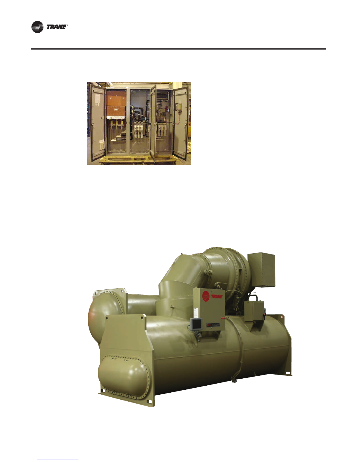
Starter Options
Figure 45. High-fault wye-delta starter
Enhanced Electrical Protection Package
Applications that require the utmost reliability and rugged construction may prompt the selection
of the Enhanced Electrical Protection Package. CenTraVac chillers equipped with the Enhanced
Electrical Protection Package are constructed to NEMA 4 guidelines and feature completely
enclosed wiring in seal-tight conduits and junction boxes.The Enhanced Electrical Protection
Package control panel also includes some additional installation features and layout
improvements.The purge is also upgraded to NEMA 4 construction.The entire chiller is silicone-
friendly—all silicone is encapsulated and non-volatile so it does not affect any industrial and/or
chemical processes.
Figure 46. CenTraVac with Enhanced Electrical Protection Package (AdaptiView unit controller)
Note: Unit shown with optional, unit-mounted control power transformer (below motor terminal
box).
64 CTV-PRB004-EN
Page 65
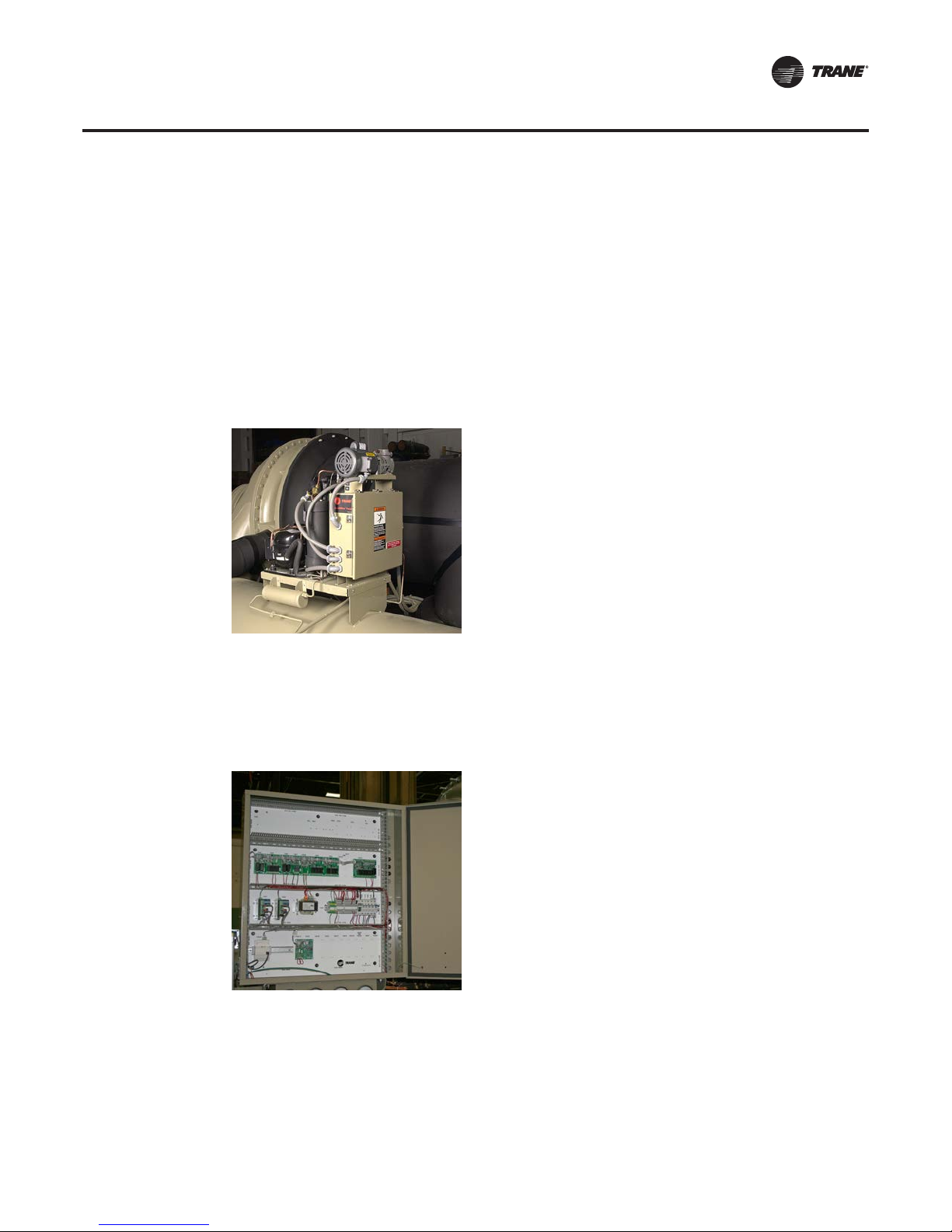
Starter Options
These and other features listed in the following section allow the CenTraVac to meet or exceed the
rigorous criteria of the Society of Automotive Engineers “Standard for Electrical Equipment for
Automotive Industrial Machinery, 2002 Edition” (SAE HS-1738). HS-1738 provides requirements
and recommendations relating to the electrical equipment of machines so as to promote:
• safety of persons and property
• consistency of control response
• ease of maintenance
Enhanced Electrical Protection Package Purge
• NEMA 4 construction
• Seal-tight conduits
• Sealed motor terminal box
• Totally Enclosed Fan Cooled (TEFC) pumpout motor
Enhanced Electrical Protection Package Control Panel
• NEMA 4 construction
• accessory port circuit breaker
• screw-type terminal block connections
• welded seam construction
Enhanced Electrical Protection Package Chiller Enhancements
• SAE HS-1738
• Warning markings
• Phenolic (permanent) labels on control devices
• Silicone-friendly to industrial processes—all utilized silicone is encapsulated and non-volatile
• Polycarbonate junction boxes listed NEMA 4X
CTV-PRB004-EN 65
Page 66
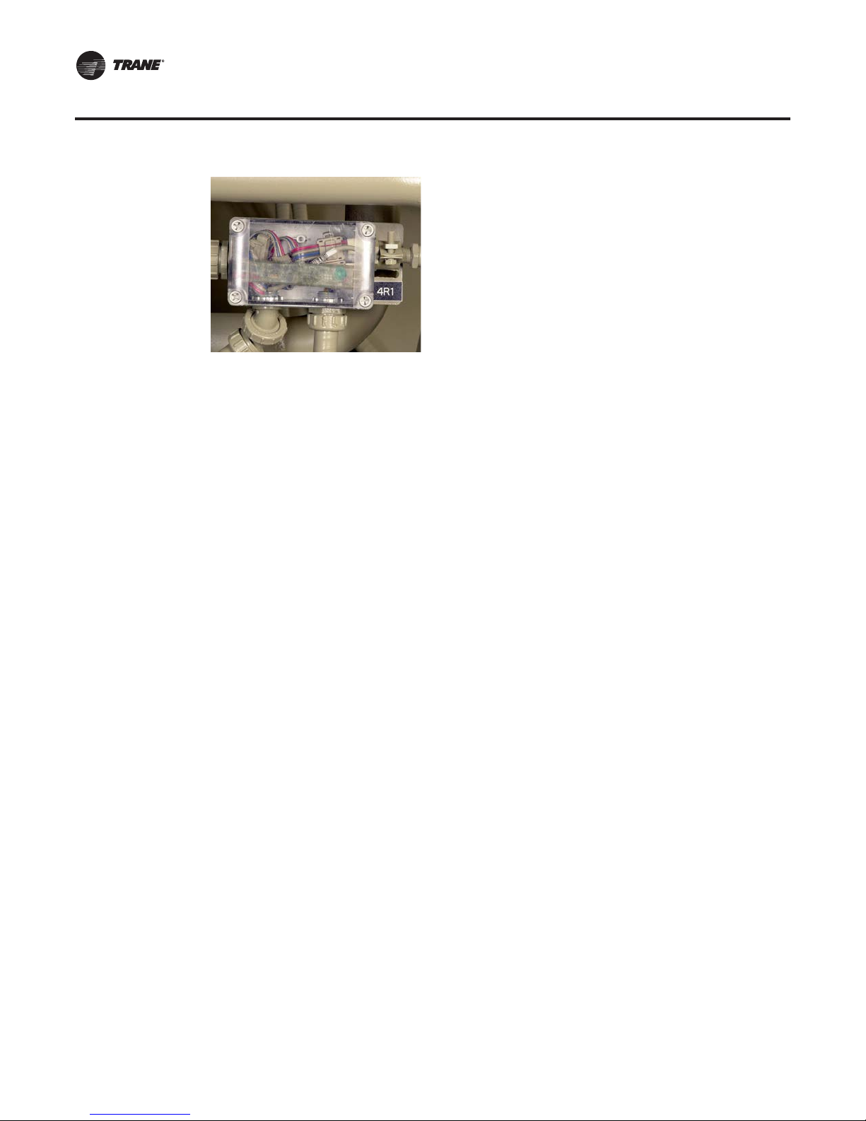
Starter Options
Enhanced Protection (EPRO)
The Enhanced Electrical Protection Package includes the EPRO package, which includes sensors
and transducers that enable the following chiller protection features:
Enhanced condenser-limit control. Factory-installed condenser-pressure transducer with
interconnecting piping and wiring provides enhanced high-pressure cutout avoidance by
energizing a relay to initiate head relief.
Note: This protection is in addition to the standard high refrigerant-pressure safety contact.
Compressor-discharge refrigerant temperature protection. Factory-installed sensor and
safety cutout on high compressor-discharge temperature allows Tracer AdaptiView to monitor
compressor discharge temperature and display the temperature at the chiller controller and at
Tracer Summit™.
Bearing oil temperatures. Factory-installed sensors allow high-temperature safety cutouts to
monitor the leaving bearing oil temperatures and display the temperatures at the chiller controller
and atTracer Summit.
The high bearing-temperature cutout is fixed at 180°F (82.2°C). If either bearing temperature
violates the cutout, a latching (manual reset) diagnostic is generated.
Enhanced Electrical Protection Package Options
In addition to the above standard elements, customers who purchase the Enhanced Electrical
Protection Package have additional options.These options can be applied to remote-mounted
medium-voltage starters, both from Trane and from other starter manufacturers.
CPTR, Control-Power Transformer (Enhanced Electrical Protection Package option). 4
kVA control-power transformer mounted on the chiller (480 to 115 volts)
• Flanged disconnect
• Fused primary and secondary power
• Secondary fuse status indictor (blown or not-blown)
• UL 508Type 12 construction
• Unit-mounted and factory-wired
SMP, Supplemental Motor Protection—Medium voltage only (Enhanced Electrical
Protection Package option). A separate enclosure mounted to the motor includes:
• Surge capacitors
• Lightning arrestors
• Zero-sequence ground fault
Other features:
• UL 347 tested Type 12 construction
• Field-accessible terminal block for trouble-shooting via panel
• Unit-mounted and factory-wired
66 CTV-PRB004-EN
Page 67
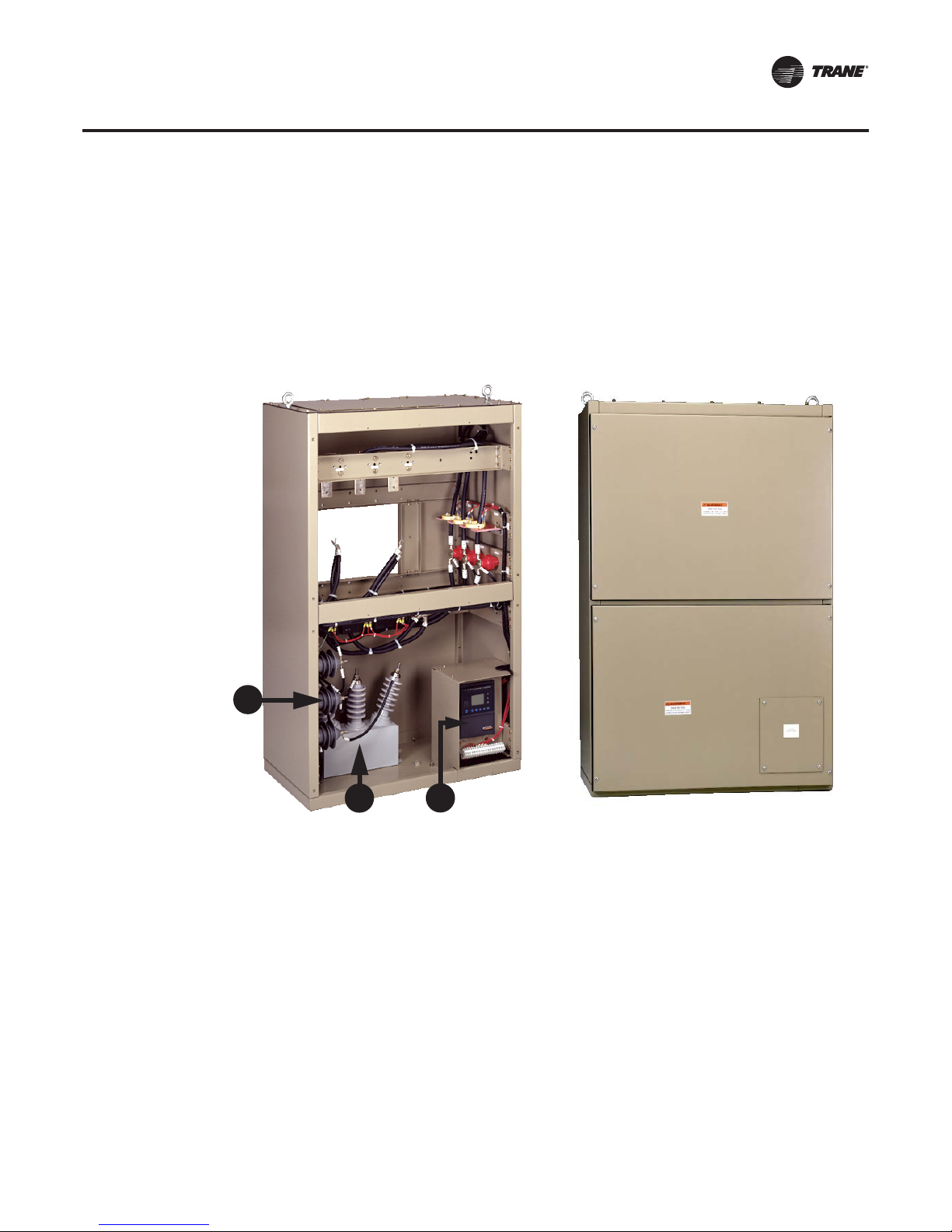
Starter Options
When the SMP option is selected, the medium voltage starter must be remote.
Note: Additional “top hat” provisions may need to be field-supplied to allow for shielded cable
with stress cones (field-provided).
DMP, Differential Motor Protection (selectable with the SMP option). DMP replaces the
zero-sequence ground fault protection. Instead, it uses a flux-summation, self-compensating
differential protection scheme for a quicker and more precise removal of line power during a fault
(see “Differential motor protection,” p. 75).
Note: DMP is available only for 1,062 kW and larger motor sizes up to 5,000 volts.
Figure 47. Supplemental motor protection enclosure with DMP option
1
2
1. Lightning arrestors
2. Surge capacitors
3. SEPAM module (Square D Electrical Protection and Metering)
3
Implications of the Enhanced Electrical Protection Package and SMP option on
customer-supplied starters (SBO). Most of the accommodations that would need to be met by
the customer who wishes to use a non-Trane starter are provided with the Enhanced Electrical
Protection Package and the SMP option.
Note: Trane-supplied starters already include these items.
The supplemental motor-protection enclosure will include:
• Primary, single-stage current transformer in lieu of primary and secondary CTs
The oversized control panel will include:
• Second-stage PTs, 115 to 30 volts, for medium-voltage applications only
• Three-pole disconnect
• Industrial terminal block for field control and control-power connections
CTV-PRB004-EN 67
Page 68

Starter Options
The customer is still responsible for providing primary potential transformers for medium voltage.
Criteria for the Enhanced Electrical Protection Package. The Enhanced Electrical Protection
Package may be selected for CenTraVac chillers that meet the following criteria:
• Single compressor (no Duplex™)
• 60 Hz only
• 080, 142, 210, and 250 shells in all short, long, and extended combinations
• Motor frame sizes 440E, 5000, 5800, and 5800L, which correspond to approximate chiller
capacities from 450 to 2,000 tons
• NEMA 1 unit-mounted starters can be accommodated. Contact CenTraVac Field Sales Support
for details.
Refer to CTV-PRC007-EN (Product Catalog: EarthWise™ CenTraVac™Water-Cooled Liquid Chillers)
for information on possible special configurations.
Note: Placing a unit-mounted starter on an chiller equipped with the Enhanced Electrical
Protection Package negates the chiller’s NEMA 4 rating and changes it back to a standard
NEMA 1 rating.
Industrial paint. Trane offers a two component, catalyzed, executive beige high-solids epoxy
coating paint system to meet or exceed the performance of the US Department of Defense
(USDOD) military specification MIL-PRF-22750F.This paint has a volatile organic compound (VOC)
content less than 2.8 lb/gal (335.6 g/L). It offers protection and resistance to fluids, adhesives,
solvents, heat, and weather. We recommend that it be used with the “Enhanced Electrical
Protection Package,” p. 64; it is priced separately.
Starters by Other Manufacturers (SBO)
Occasionally a customer chooses to reuse an existing starter or purchase a starter directly from a
starter manufacturer. While this can be accommodated, it requires careful coordination between
theTrane sales representative and the owner, engineer, and starter manufacturer because generic
or existing starters are not compatible with theTrane
Non-Trane starters must be modified with the proper components and control wiring before they
®
are connected to aTrane
chiller. Existing starters should be modified by the owner’s
representative; new starters should modified by the starter manufacturer.Trane assumes no
responsibility for the design, construction, compatibility, installation, startup, long-term support,
and will not maintain records or drawings for the resulting starter.
Trane provides a Starter by Others specification, which provides the information required for
others to build a starter that is compatible withTrane
When a non-Trane-provided starter is used, it must be modified to conform to the appropriateTrane
Starter by Others specification. SBO specifications are revised on a regular basis, so it is important
to obtain the correct version before building or modifying a starter by others.
It is also important to include the cost of conversion when determining the total cost of a non-Trane
starter; therefore, the owner should be provided with the appropriate SBO specification before the
decision is made to reuse or purchase a non-Trane starter. Components required for conversion
include but are not limited to:
• 4 kVA control-power transformer (1)
• Primary current transformers (3)
• Secondary current transformers (3)
• Primary potential transformer (1) for medium-voltage starters
• Secondary potential transformers (3) for medium-voltage starters
• Other optional starter equipment, e.g. power factor correction capacitors, as required by the
specification
TheTrane
®
chiller control panel integrates the chiller, motor, and starter into a single control and
protection system.Therefore, non-Trane starters do not require an additional motor-starter
protection package. If a non-Trane starter includes a protection package, the protection package
®
chiller control panel.
®
centrifugal compressor motors and controls.
68 CTV-PRB004-EN
Page 69

Starter Options
must be disabled or the sensitivity of all the starter trip levels must be readjusted so that theTrane
control panel acts as the primary protection for both the chiller and the starter.
Chillers used with non-Trane starters must ship with a special control panel to accommodate the
non-Trane starter. It is the responsibility of theTrane sales representative to select the “Starter by
Others (SBO)” option when pricing the chiller and to assure that the non-Trane starter is built
according to the proper “Starter by Others” specification.
Note: The Enhanced Electrical Protection Package can simplify the procedure for using a non-
Trane starter; see “Implications of the Enhanced Electrical Protection Package and SMP option
on customer-supplied starters (SBO),” p. 67.
In summary, when a customer wants to buy a starter from a manufacturer other than Eaton CutlerHammer
®
, the procedure is as follows:
1. Price the appropriate customer-supplied starter.
2. Provide a copy of the “Starter by Others” (SBO) specification S6516-0513 from CenTraVac Field
Sales Support to the customer/starter manufacturer.This specification lists the allowable
starter types.
3. Inform the customer that Trane assumes no responsibility for
the design, construction,
compatibility, installation, startup, long-term support, and will not maintain records or
drawings for the resulting starter.
Power Factor and CenTraVac Chiller Motors
CenTraVac squirrel-cage induction motors normally have an uncorrected full-load power factor of
88 to 92 percent. The power factor decreases slowly as the motor’s torque output drops from full
load to approximately 50 percent, and then falls more rapidly at lower loads. If the full-load power
factor is corrected to 95 percent, the entire curve shifts upward and the corrected power factor
remains at a high value (Figure 48, p. 70). The current (amps) for a motor with a corrected power
factor is lower than the current for a motor with an uncorrected power factor.
In some cases, a power factor greater than 95 percent is specified for “all load ratios above
40 percent” or at a particular operating point. Multiple-capacitor arrangements with an elaborate
switching mechanism can provide this level of correction without overcorrecting by “cycling”
various capacitor combinations on and off as motor loading dictates; however, this arrangement
is complex and its cost may be prohibitive.
Typically, specifications stipulate a corrected power factor of 95 percent at full load.This results in
an economical application that balances the fir st cost of the capacitors with the benefits of a higher
power factor.
Several equations are helpful:
®
ApparentPower(kVA) =
ActualPower(kW) =
CTV-PRB004-EN 69
ActualPower(kW)
PowerFactor 1000
=
Volts x Amps x 3xPF
1000
Volts x Amps x 3
Page 70
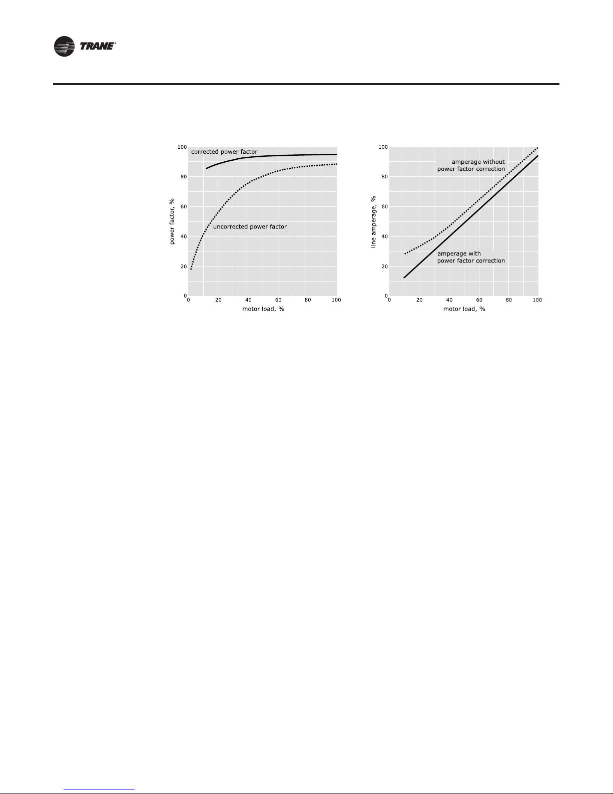
Starter Options
Figure 48. Typical CenTraVac chiller-motor power factor
PFCC Placement and Sizing. PFCCs may be installed at various locations in the power supply
network. Utility companies install capacitor banks on their distribution feeders and substation
buses.These capacitors correct for the utility’s reactive loads and for other large reactive loads,
such as those found in business or industrial areas.
When utility customers correct for the reactive loads in their facilities, they usually install PFCCs
at the facility’s electrical service entrance or at the individual loads within the facility. Connecting
the PFCCs at the service entrance corrects reactive loads throughout the facility.This strategy can
be advantageous if the facility contains a large number of small reactive loads—but it can also be
costly. Successful implementation requires expensive hardware to monitor the power factor as
loads are added to and removed from the distribution system, then switch capacitors on- and
offline accordingly.To avoid this expense, PFCCs are most commonly installed near each piece of
switchgear that supplies a reactive load.
EngineeringToolbox. Trane has a program called EngineeringToolbox, available online or
throughTrane Desktop Manager, that can be used to calculate the kilovolt-amperes reactive (kVAR)
of correction needed.Toolbox can calculate kVAR using information from the motor data sheets
without adjustments at 60 and 50 Hz. Contact yourTrane sales representative for more information.
PFCC Application Guidelines. Three “rules” govern the application of capacitors dedicated to
a specific reactive load and its switchgear:
• “Rule 1”—Simultaneously disconnect capacitors and load from line power
• “Rule 2”—Size motor overload protection to account for capacitor-supplied current
• “Rule 3”—Accurately size PFCCs that remain connected to the motor when it is offline
These guidelines are explained on the following pages.
Rule 1—Simultaneously disconnect capacitors and load from line power.
If the capacitors are not switched offline when the load is disconnected, they continue to add
capacitance to the electrical distribution system. A “leading” power factor—too much capacitance
may eventually develop.This overcorrection causes poor voltage regulation, i.e., voltage is high
when the circuit is unloaded, then drops as loads are added.
Rule 2—Size motor overload protection to account for capacitor-supplied current.
Overloads are typically set to measure the total current drawn by the motor.When PFCCs are used,
they become another source for a part of that current. If the current they provide is not “seen” by
the overload protectors, potentially damaging amperage can reach the motor.The simplest way
to ensure that the overloads “see” all current supplied to the motor is to position the PFCCs
upstream of the overloads as shown in Figure 49.
70 CTV-PRB004-EN
Page 71

Starter Options
Figure 49. PFCCs installed downstream of starter contactor, upstream of overloads
or
Motor Starter
Contactor
Enclosed
Capacitor Unit
3-Phase
Capacitor
Overload
Protectors
Fuses
Motor
Power
Circuit
1
2
3
Fusible
Safety Switch
Suitable Breaker
If the capacitor connection points are downstream of the overload devices, route the PFCC leads
through the overloads as shown in Figure 50, p. 71.This assures that the overloads register both
line- and capacitor-supplied current.
Figure 50. PFCC wires routed through overload protectors
Fusible
Safety Switch
Suitable Breaker
1
2
or
Overload
Protectors
Motor
3
Power
Circuit
Enclosed
Capacitor Unit
3-Phase
Capacitor
Fuses
Motor
Starter
Contactor
Rule 3—Accurately size PFCCs that remain connected to the motor when it is offline.
Connecting PFCCs to the load side of the motor-starter contactor is commonly used as a simple,
low-cost way to comply with “Rule 1.” However, the motor may be damaged if the PFCCs are too
large. As a “rule of thumb,” the maximum corrected power factor is 95 percent for a CenTraVac
chiller motor operating at full load.
Failure to comply with this rule can cause significant damage due to voltage regeneration. The
manufacturers of CenTraVac chiller motors place maximum limits on both the corrected power
factor and the capacitor size. PFCCs that remain connected to the motor when it is offline must not
exceed the motor manufacturer’s maximum limit.
CTV-PRB004-EN 71
Page 72
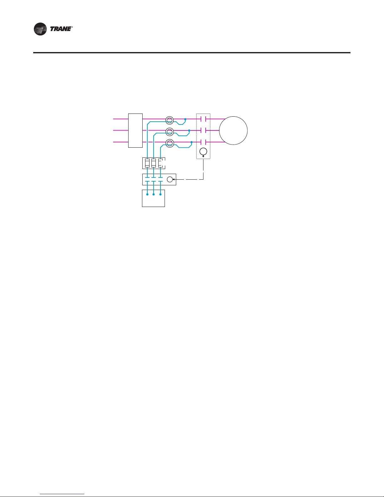
Starter Options
Figure 51. PFCCs with separately controlled motor contactor
Fusible
Safety Switch
Suitable Breaker
1
or
Overload
Protectors
2
3
Power
Circuit
Fuses
Enclosed 3-Phase
Capacitor Unit
PR
C
Motor
Motor Starter
Contactor
or
Silicon-Controlled
Rectifiers (SCRs)
Line-side PFCC placement. Figure 51, depicts an arrangement that provides an alternative to
installing capacitors downstream of the motor-starter contactor. While this configuration can be
used with any type of starter, it is mandatory for all solid-state starters. Notice that the PFCCs are
connected to the line side of the main contactor (or other switching device) via a separately
controlled contactor.Thisseparate contactor is governed by a pilot relay (PR) at/in the motor-starter
contactor or silicon controlled rectifiers (SCRs, solid-state starter applications) to switch the
capacitors on- and offline with the load.
By connecting the PFCCs through a separate contactor they do not remain connected to the motor
or the line when the motor is disconnected.This configuration prevents voltage-feedback problems
and can be used for cases where correction beyond 95 percent is desirable. Correction beyond the
manufacturer’smaximum limit should not be done without consulting the manufacturer regarding
the application.
If the PFCC connections are downstream of the overloads, the capacitor leads must be routed
through the overloads as Figure 51, p. 72 illustrates. Notice that the capacitors are not connected
to the motor when it is disconnected from the line.This prevents the “motor-generated voltage
buildup” described in “Rule 3”, p. 71.
72 CTV-PRB004-EN
Page 73

Glossary
A
Acceleration time
The time it takes a motor to reach full design speed from
the moment power is applied. Typical CenTraVac motor
acceleration times associated with various starter types
are listed in Table 5, p. 17 (low voltage) and Table 7, p . 31
(medium voltage).
Advanced motor protection system
Standard motor protection provided by the CenTraVac
microprocessor-based control panel. By monitoring
current and voltage in each of the three motor power
phases, the panel provides protection throughout the
motor starting and running modes from the adverse
effects of phase imbalance, phase failure, phase reversal,
overvoltage, undervoltage, and electrical distribution fault
(momentary power loss). Sensing any of these faults, the
panel trips-out the motor instantaneously and provides a
diagnostic display. The chiller controller also protects
“adaptively” for overcurrent. By reducing the load, it may
be able to avoid a shutting down the chiller once it reaches
the current limit.
Automatic restart is provided after restoration of power
when
the
stoppage is caused by distribution fault or
extended power loss.
Air break
Contacts exposed to open air that rely on an air gap to
keep an electrical circuit open. Air break contactors are an
obsolete technology that has been replaced by vacuum
break contactors. See “Vacuum break,” p. 81.
Aluminum conductors
Trane requires that power wiring to the motor use copper
conductors. Aluminum conductors are not suitable for the
following reasons:
•UL requirements
•Galvanic corrosion
•Higher probability of connection failure
•Terminal block design
Galvanic corrosion occurs
present at an aluminum-copper connection. The resulting
electrolysis process causes the loss of aluminum at the
interface of the dissimilar metals.
Another reason to use copper conductors is the
decreased
connections require greater care at initial installation as
well as periodic maintenance and inspection because of
probabilit
when
air and moisture are
y of connection failure. Aluminum
oxidation, torque requirements, cold flow, and thermal
expansion coefficients.
Greater care in connecting aluminum wire is required
since
an aluminum
penetrated before a reliable aluminum joint can be made.
This oxide film insulates the aluminum and increases joint
resistance.
Torque requirements are
connections are made. It is difficult to ensure that these
requirements will be met at the time of installation.
Cold flow or
lower modulus of elasticity than copper and tends to
creep away from a stressed area when under pressure.
The resulting loosened connection can increase joint
resistance and lead to failure of the connection. Periodic
maintenance and inspection is required to assure good
connections.
Aluminum and copper have different thermal
coefficients. Aluminum expands 36 percent more than
copper under
connections are subjected to a large temperature change,
a gap may open between the aluminum cable and the
copper lug. This, combined with cold flow, can result in a
very high resistance joint and lead to failure of the
connection.
The final reason to use copper conductors is terminal
bloc
k
design. Because aluminum electrical conductivity is
about 60 percent that of copper, larger aluminum cables
are required
These larger cable sizes may not fit terminals designed for
copper. It is also possible that the block itself may not be
suitable for use with aluminum wire as determined by the
block manufacturer.
oxide film must be removed or
critical
when aluminum
“creep”
thermal cycling. When the terminals and
to conduct the same amount of current.
results because aluminum has a
e
xpansion
Amps, motor full-load amps (FLA)
FLA is the amperage the motor would draw if it was
loaded to its full rated capacity, i.e. motor size kW. The
FLA is not available from the selection program; however,
it can be obtained from CenTraVac Field Sales Support.
Amps, motor locked-rotor amps (LRA)
Once a motor has been selected, there is a specific locked
rotor amperage value associated with the specific motor.
This is the current draw that would occur if a motor was
running, and then the rotor shaft was instantaneously held
stationary. LRA is typically 6–8 times that of the motor fullload
discussing different starter types and the amperages
associated with the start.
(FLA). LRA is also used commonly in
amps
CTV-PRB004-EN 73
Page 74

Glossary
Amps, primary rated-load amps (RLA)
Commonly referred to as the selection RLA or the unit
RLA. This is the amperage that is drawn when the chiller
is at full cooling capacity in terms of cooling tons (kW).
RLA is listed on the nameplate, and it is the key number
used to size the starter, disconnects, circuit breakers, and
Adaptive Frequency Drives (AFD) for a typical chiller. It is
also the value used to determine the minimum circuit
ampacity (MCA) for sizing conductors. Primary RLA is
always less than or equal to the motor full-load amps
(FLA).
Anti-recycle protection
A control method that limits the number of compressor
starts within a given time period. Prior to 2000, the
CenTraVac was limited to one start every 30 minutes
(30 minutes from start-to-start).
Today, a more flexible protection system called restart
inhibit
allowed before a time limit is set. The time limit, if
enforced due to several rapid restarts, is dependent on
motor winding temperature, unit size, and an adjustable
delay time constant.
This protection is a standard feature of the CenTraVac
control
utilized. Typically several rapid restarts are
is
panel.
Available fault current (AFC)
Electrical engineers usually calculate and design to a
potential short-circuit current that originally comes from
the utility power system. They call this term the available
fault current because they take the potential fault current
and then evaluate it via computer programs to determine
an available fault current just upstream of the chiller
starter or frequency drive. The starter short-circuit current
rating should be greater than or equal to the available fault
current to safely contain starter components should a
short-circuit occur.
B
Bus
A bar of conductive material—usually copper—used to
carry large electrical currents to supply multiple circuits or
components. A bus is typically used to connect several
medium-voltage starters together and thereby require
only a single power connection for incoming line power.
C
California code
Available on CenTraVac chillers with low-voltage starters
(UL as standard) with disconnects or circuit breakers. Low-
voltage starters with terminal blocks require a special
configuration which is available as a standard option in the
order system. On medium voltage, the standard UL
certification satisfies California Code requirements.
Circuit breaker
A device that protects a circuit by opening its contacts
when a current responsive element senses overcurrent or
short-circuit current. A circuit breaker protects electrical
components from further damage if any one component
within that system experiences a short circuit. Circuit
breakers are used on low-voltage starters only.The
overload function is not used; overload is accomplished by
the chiller controller. Circuit breakers are sized based on
the primary RLA from the nameplate, the required AIC of
the breaker, and the required SCCR of the starter
enclosure.
Contactor
A multi-pole relay whose contacts are rated to carry line
current. The contactor connects and disconnects a motor
to and from line power.The coil of a contactor may be
operated by line voltage, control voltage, or through a
rectifier (DC voltage).
Control-power transformer (CPT)
A device that reduces incoming line voltage to control
voltage (i.e., 480 Vto120V). The control-power
transformer
transformer is provided as standard in CenTraVac
starters—3 kVA transformer provided with AFDs. The
Enhanced Electrical
to mount the CPT separately on the side of the chiller.This
transformer takes care of the chiller’s auxiliary power
needs such as the purge, oil pump, heater, etc.
is usually located in the starter. A 4 kVA
Protection Package provides an option
Corona
A visible pale glow surrounding an insulated conductor
typically carrying over 2000 volts. Ozone odor is present
and the
in voltage may cause the corona effect of adjacent wires
to increase until spark-over occurs. See “Stress cone
(stress relief cone),” p. 80.
air around the wire becomes ionized. An increase
Current-limiting fuse
A current-limiting fuse is a fuse that recognizes the rate of
current increase and will melt its element and open the
circuit in less than one-quarter of an electrical cycle in the
event of a short circuit. Thus, the total short-circuit current
available never passes through the current-limiting fuse.
CenTraVac medium-voltage starters contain three currentlimiting fuses as standard.
74 CTV-PRB004-EN
Page 75

Glossary
Current transformer
A device that produces a reduced current signal that is
proportional to the primary current. A current transformer
may resemble a square or round doughnut. Each motor
lead passes through the center of a current transformer
and a reduced proportional current signal is obtained at
the current transformer leads. There is no direct electrical
connection between the motor lead and the current
transformer. The voltage in the output circuit of a current
transformer will be whatever voltage is necessary to drive
the output current through the load with the voltage
limited only by the line power or saturation level of the
current transformer; therefore, the secondary of a current
transformer must never see an open circuit.
D
Differential motor protection
Means of detecting current leakage in a motor from
winding-to-winding or from winding-to-ground. Differential
motor protection requires a six lead motor. Three current
transformers, one for each motor phase, monitor the
current in and out of each of the motor windings. If, due to
leakage or some fault within the motor, the current in and
the current out are not identical in each winding, a current
will be induced in the secondary of one or more of the
current transformers. This induced current will energize a
differential relay which will open a contactor and deenergize the motor.
Differential protection is available as part of the Enhanced
Electrical
protection option. Differential protection is not applicable
to Trane’s standard, low-voltage wye-delta starters.
Differential relay
Current sensitive relay that has three coils, each
connected to one of the current transformers used for
differential protection. Energizing any one of the three
coils will operate the relay. A differential relay is furnished
with the differential protection option.
Disconnect
A device for manually isolating an electrical circuit.
Distribution fault
Transient power losses longer than 2 or 3 cycles will be
detected and cause the chiller to shut down, typically
within 6 cycles. The chiller can also shut down due to
ex
cessive or rapid voltage sags. Shutting down the chiller
prevents the motor having power reapplied with different
phasing. Utility power outages are not considered
P
rotection Package’s supplemental motor
distribution faults—Trane refers to this type of fault as a
momentary power loss (MPL).
E
Enclosure
The sheet metal structure and access door that surrounds
the starter.The standard enclosure is NEMA Type 1,
which
means general purpose indoor with a gasketed
access door. Other enclosure classifications to meet
requirements of different environments are available as
special options. See “NEMA 1,” p. 78.
F
Full-load amps (FLA)
See “Amps, motor full-load amps (FLA)”, p. 73.
Fuse
A device that protects a circuit by fusing (melting) open its
current-responsive element due to an overcurrent or
short-circuit current. A fuse protects electrical
components from further damage if any one component
within that system experiences a short circuit.
Fuse - dual element
A dual element fuse is a single cartridge fuse having two
different current-responsive elements in series. A dual
element fuse is required to carry 500 percent of its
current
current-responsiv
characteristics while the other element will handle larger
currents without intentional time delay. Since most
CenTraVacs draw inrush currents in excess of this rated
minimum ampacity during acceleration, all low-voltage
CenTraVacs with fuse protection must use dual element
fuses.
rating for a minimum of 10 seconds. One of the
e elements will have inverse time
Fuse rating
NEC code allows a maximum fuse rating that is
175 percent of the RLA. To prevent blowing fuses during
motor acceleration
increase up to 225 percent of the RLA. CenTraVac dual
element fuses
RLA.
this maximum value is allowed to
are sized at 150–195 percent of the chiller
G
Ground fault
A leakage of line current to ground. Ground faults are
typically caused by the breakdown or cracking of wire
insulation.
CTV-PRB004-EN 75
Page 76

Glossary
Ground fault protection—low voltage
Low voltage ground fault protection consists of a ground
fault sensor, a ground fault relay, and a disconnect device
(circuit breaker or non-fused disconnect switch) equipped
with a shunt trip device.
The ground fault sensor is a specially rated current
transf
relay. Ground fault sensors cannot be used with any other
equipment.
The ground fault relay is designed to work with a ground
f
sensor. The current level required to activate the
ault
ground fault relay is adjustable. The response speed (time
delay) is also adjustable to avoid nuisance trips. All ground
fault relays require a manual reset. The time-current
tripping curve of a ground fault relay is nearly
instantaneous when the current setting and time delay
have been exceeded.The contacts of the ground fault
relay energize a shunt trip device to open the circuit and
isolate the ground.
The shunt trip device is a circuit breaker with a shunt trip
coil.
Suc
opened by its current sensing element (short circuit), or
opened by energizing its shunt trip coil. A circuit breaker is
used to open the circuit because it is capable of
successfully interrupting fault current; the current to
ground may be catastrophic.
The minimum setting of the ground fault protection
sy
stem
a 1
0-cycle time delay.
and must be applied only with a ground fault
ormer
h a circuit breaker can either be opened manually,
should be 20 percent of the disconnect rating with
Ground fault protection—medium voltage
Medium voltage ground fault protection consists of a
ground fault sensor and ground fault relay.The ground
fault relay interrupts control power to the main contactors
causing them to open. All medium-voltage starters are
equipped with current-limiting fuses. In the event of a
catastrophic ground, the current-limiting fuses would
react much faster than the ground fault protection relay;
therefore, the fuses would perform the act of interrupting
the circuit and isolating the ground.
The minimum setting of the ground fault protection
sy
a 1
should be 20 percent of the disconnect rating with
stem
0-cycle time delay.
Grounding
Electrical refrigeration components such as motors and
control panels must be grounded for the protection of
maintenance and service personnel.
Equipment ground connection bolts are provided in the
control
all CenTraVacs. On those CenTraVacs where the control
panel is isolated, grounding straps are installed to ground
the control panel to the chiller frame. Thus, all pieces of a
CenTraVac are provided with an individual equipment
ground.
It is the responsibility of the inst alling contractor to ground
the
CenT
local codes.
the motor junction box, and in the starter of
panel,
raVac equipment to an earth ground per NEC and
“Gutless” circuit breaker
See “Non-fused disconnect”, p. 78.
I
Inrush current
The current drawn by a motor during acceleration. Inrush
current for various types of starters (in percent of LRA) is
given in Figure 6, p. 18 (low voltage) and Figure 22, p. 31
(medium voltage).
Interlock, electrical
Auxiliary contacts on a contactor, typically used in control
voltage circuits, to monitor the position of the contactor.
These auxiliary contacts may be normally open, normally
closed, or convertible.
Interlock, mechanical
Bars, levers, or catches that physically prevent operation
of a device under certain circumstances. (i.e. a CenTraVac
starter door may not be opened if a circuit breaker is
closed)
Interrupting capacity
The rated maximum current that a device can successfully
interrupt without damage to itself. This applies to a circuit
breaker or a fuse only. It is not proper to refer to a starter
as having an interrupting capacity. Starters have an overall
short-circuit current rating. See “Short-circuit current
rating (SCCR)”, p. 79.
Ionization
Insulated conductors carrying over 2000 volts are subject
to ionization. Ionization results in the formation of gas
pockets between the insulation layers.These gas pockets
form areas of unequal stress that may lead to premature
breakdown of the insulation. See “Stress cone (stress
relief cone)”, p. 80.
IQ digital meters
This is a starter mounted meter that digitally displays
many parameters. It is a st arter option, however most
76 CTV-PRB004-EN
Page 77

Glossary
functions are displayed as standard on the unit controller.
See the comparison tables (Table 2, p. 13 and Table 3,
p. 14).
Isolation switch
A device used to connect and disconnect a load to and
from line power for servicing. Isolation switches are nonload break and cannot be opened under load. Trane
medium-voltage starters have a mechanical interlock that
prevents the isolation switch from being opened while the
chiller is running. This is a standard item on Trane
medium-voltage starters.
®
®
K
Kirk key
A locking arrangement between a remote disconnect
switch and a starter that is designed to prevent closing the
remote switch and powering the starter that is being
serviced.
A single key is used and it is held captive in the disconnect
switc
locked open. The kirk key may then be removed and used
to unlock the starter.The key remains captive in the
starter until the starter door is closed and locked. The key
may then be removed and used to unlock the disconnect
switch.The switch may then be closed.
The disconnect switch must be opened and then
h.
voltage starters when customers want Trane to provide a
load-break switch. The standard isolation switch that
comes with medium-voltage starters is non-load break.
The load-break switch is a design special. The switch is
housed within a 90" high, 36" wide, and 30" deep
enclosure. A circuit breaker or non-fused disconnect on
low-voltage starters can be used as a load-break switch.
Locked-rotor amps (LRA)
See “Amps, motor locked-rotor amps (LRA)”, p. 73.
Lug
A device used to mechanically connect a conductor (wire)
to a piece of electrical equipment. Lugs are furnished by
the starter vendor.The number of wires per phase and
range of wire sizes that the lugs will accept are listed in
the starter submittals. The range of wire sizes indicates
the maximum size wire that will fit into the lug hole and
the minimum wire size that the screw can securely clamp
in place. Optional lugs that accommodate different
number of wires per phase and size are generally available
for every starter.These can be purchased through a local
vendor if required.
Note:Wire sizes “pulled” by contractor that are different
from
the
lug sizes shown on the starter submittal
will impact the lug sizes needed. In this case, the
correct lug sizes must be obtained locally.
L
Lightning arrester
A device that protects electrical equipment from high
voltage spikes by providing a high resistance path (an air
gap) to ground—essentially an air gap small enough to
allow a spark-over to occur for voltages much larger than
the chiller’s operating voltage. The device provides
protection by consistently conducting to ground when the
magnitude of the voltage exceeds a predetermined value.
Although lightning arresters may be used alone, they are
used
usually
capacitors.
The function of a lightning arrester is to limit the
magnit
capacitor is to limit the rate of rise of a voltage spike. See
“Surge capacitor,” p. 80.
Lightning arresters are a starter option.
Load-break switch (LBS)
A manual switch that has an interrupting rating and can be
used to safely interrupt a live circuit. It is sometimes called
an ADM switch.This term is typically used with medium-
in conjunction with surge protection
of a voltage spike. The function of a surge
ude
M
Maximum overcurrent protection (MOP)
The maximum overcurrent protection (MOP, or sometimes
abbreviated as MOCP) appears on the chiller nameplate.
The electrical engineer often wants to know the MOP
when selections are being made. It is used to assist in the
sizing of fuses and circuit breakers. MOP is an output of
the TOPSS selection program. Also see the discussion on
fuse and circuit breaker sizing (“Electrical System—
Ratings,”p
Guidelines,”p.
breakers can result in nuisance trips during the starting of
the c
value used to size incoming wire (see MCA).
Minimum circuit ampacity (MCA)
This term appears on the chiller nameplate and is used by
electrical engineers to determine the size and number of
conductors bringing power to the starter. The formula for
MCA is 1.25 x (Primary RLA) + (4000/motor voltage),
rounded up to the next whole number. The formula is
125 percent of the motor design RLA plus 100 percent of
the
.49 and “Electrical
52). Use of improperly sized circuit
hiller. For CenTraVac chillers the MOP is NOT the
amperage
of other loads (control-power transformer,
System—Design
CTV-PRB004-EN 77
Page 78

Glossary
oil pump motor, and purge etc.) MCA is an output of the
TOPSS selection program. Table 11 , p. 58 through
Table 16, p. 60 show power wire sizing based on the
MCA.
Molded case switch
See “Non-fused disconnect”, p. 78.
Momentary power loss (MPL)
See “Distribution fault”, p. 75.
Motor FLA
See “Amps, motor full-load amps (FLA)”, p. 73.
Motor LRA
See “Amps, motor locked-rotor amps (LRA)”, p. 73.
Motor size in kilowatts (kW)
The motor size is listed on the program output in kW. This
is the motor’s full, rated capacity.There is an amperage
draw associated with power draw at full capacity called
full-load amps (FLA). FLA is the amperage the motor
would draw if it is loaded to its full rated capacity i.e.
motor size kW.The FLA is not available from the TOPSS
selection program, however can be obtained from
CenTraVac Field Sales Support.
Usually the selection RLA and kW are used as the
nameplate
decide to specify slightly higher RLA as the nameplate
data to provide “extra” capability for the chiller. The higher
kW and RLA cannot exceed the motor size (kW), the
starter size (RLA), or the disconnect/circuit breaker size
(RLA).
and kW. Occasionally, an engineer may
RLA
N
NEMA 1
Enclosures are intended for indoor use primarily to provide
a degree of protection against limited amounts of falling
dirt.
NEMA 12
Enclosures are intended for indoor use primarily to provide
a degree of protection against circulating dust, falling dirt,
and dripping non-corrosive liquids.
NEMA 3R
Enclosures are intended for outdoor use primarily to
provide a degree of protection against rain, sleet, and
damage from external ice formation.
NEMA 4
Enclosures are intended for indoor or outdoor use
primarily to provide a degree of protection against
windblown dust and rain, splashing water, hose-directed
water, and damage from external ice formation.
NEMA 4X
Enclosures are intended for indoor or outdoor use
primarily to provide a degree of protection against
corrosion, windblown dust and rain, splashing water,
hose-directed water, and damage from external ice
formation.
Non-fused disconnect
A circuit breaker without a thermal or magnetic
overcurrent element. It is used solely as a manual
disconnect means. This is also called a “gutless” circuit
breaker or molded case switch.
O
Overload protection
A scheme or device that monitors motor current and
interrupts control power to the main contactor(s),
disconnecting the motor from the line, if motor current
exceeds preset limits of current and time. Motor current
may be monitored directly or through current
transformers.
Overload relay
A device that senses current flow to a motor. The relay
can be set to trip at a certain value. If the motor attempts
to draw current in excess of this value, the relay will trip,
de-energizing the contactor coil, disconnecting the motor
from the line.
P
Phase failure
An opening in one of the three main power leads caused
by a blown fuse or broken conductor.This results in only
one phase being delivered to the load. Thus, phase failure
is the same as single phasing. Phase failure protection is
standard on CenTraVac chillers with microprocessor-based
chiller control panels and was available as a starter option
on older CenTraVacs.
Phase imbalance
An imbalance in the current level or voltage level among
the three phases. Phase imbalance can cause motor
overheating.
Phase reversal
A change in the desired electrical phase relationship.
Phase reversal causes motors to rotate in the wrong
direction.
78 CTV-PRB004-EN
Page 79

Glossary
Phase failure/phase reversal relay
A device that monitors the phase relationship and opens a
contact to stop the compressor motor in the event of
phase failure, phase reversal or phase imbalance.
The advanced motor protection provided by the chiller
controller
reversal relay.
orms the functions of a phase failure/phase
perf
Pilot relay
A term describing the fact that all CenTraVac starters start
and stop the compressor by means of a relay that
responds to commands from the CenTraVac control panel.
Push-to-start push-buttons or any other forms of manual
starting of the compressor are not allowed. The CenTraVac
safeties in the control panel must not be bypassed.
Power factor
The ratio of real power (watts) to apparent power (volt-
amperes). Induction motors, such as CenTraVac
compressor motors, require some energy for magnetizing
that does no actual work and is not registered on a
wattmeter.
Power factor correction capacitor (PFCC)
May be used to improve the power factor of a CenTraVac
by furnishing some of the wattless magnetizing energy
required by the motor.
Power factor correction capacitors are a starter option.
T
y are mounted in or on the starter and are typically
he
wired to the load side of the compressor contactor. Since
the capacitors are wired in parallel with the motor, the
maximum capacitor size is determined by the motor.
The capacitors furnished as a starter option will correct
the
compressor
95.5 percent power factor at full load.
motor to approximately 93.5 to
Power wiring
Refer to Table 11 , p . 58 through Table 16, p. 60 for wire
sizing for line and load wire associated with CenTraVac
starters.
Primary power
The performance number called primary power is the kW
usage at chillers full cooling capacity. The primary power
will always be less than the motor size. See “Motor size in
kilowatts (kW)”, p. 78.
Primary RLA
See “Amps, primary rated-load amps (RLA)”, p. 74 .
R
Rated-load amps or running-load amps (RLA)
See “Amps, primary rated-load amps (RLA)”, p. 74 .
Relay
An electrically-operated device whose contacts switch
electrical circuits. A relay is always used as a switching
device within a control circuit.
Resistance temperature detector (RTD)
A device whose electrical resistance varies with its
temperature. RTDs may be used to monitor motor
winding temperature.
Every CenTraVac motor has three RTDs buried within its
st
windings. These RTDs are connected to the
ator
CenTraVac control panel. There, a device monitors the
resistance (hence, the temperature) of the RTDs and will
stop the compressor if the motor winding temperature
exceeds a preset level. These are dedicated RTDs and
cannot be used for any additional functions.
If motor winding RTDs are required for any other function,
the
R
TDs required must be described and ordered as a
design special. Then, a specially built motor will be
provided.
S
Short circuit
An unintentional direct electrical connection from phaseto-phase or from phase to ground resulting in low
resistance and very high current flow. Short circuits can
result in destruction of conductors and components. Short
circuits are caused by the breakdown of insulation, poor
wiring, or a conductive piece of metal that accidentally
comes in contact with multiple phases or between a
phase and ground (i.e. tools and service equipment). See
“Available fault current (AFC)”, p. 74 .
Short-circuit current rating (SCCR)
When a short circuit occurs, there is a period of time that
the short-circuit current passes to the shorted circuit
before the protection device (circuit breaker or fuse) can
open. This time can be as long as 0.020 seconds (1 cycle).
The
short-circuit current rating of a starter is the maximum
short-circuit current that it can pass safely. Components
within the starter may be destroyed, but the starter
cabinet will safely contain any sparks or flying debris. UL
listed starters have a listed short-circuit current rating.
Short-circuit withstand rating (SCWR)
See “Short-circuit current rating (SCCR),” p. 79.
CTV-PRB004-EN 79
Page 80

Glossary
Shunt trip
A tripping coil added to a circuit breaker or non-fused
disconnect to provide a means of tripping the circuit
breaker with an external signal. See “Ground fault
protection–low voltage”, p. 76 .
Silicone controlled rectifier (SCR)
A solid state signal controlled, one-way power switching
device commonly used in solid-state starters and variablefrequency drives.
Single phase (single phasing)
See “Phase failure”, p. 78.
Solid-state starter
A starter that starts and accelerates a motor at a preset
acceleration rate and current limit. A solid state starter
performs this function by modulating the current/voltage
wave form delivered to the motor with silicon controlled
rectifiers (SCRs). For more information on this starter
type, refer to CTV-SLB017-EN (Solid-State Starters for
Trane Chillers ).
Starter
A device consisting of both a contactor and an overload
protection system or device whose purpose is to start and
stop a motor and protect the motor from overcurrent.
Variable-frequency drives are also classified as starters.
Stress cone (stress relief cone)
Cables carrying above 200 0 volts must have a metallic
shield unless the cable is specifically listed or approved for
non-shielded use. Shielding is necessary because of the
danger of corona or ionization. The purpose of shielding a
cable is to confine its dielectric field to the inside of the
cable or conductor insulation. The shielding must be
grounded at one end.
Stress cones are used to reduce and control longitudinal
and
radial
electrical stresses at the cable end to values
within safe working limits for the material used to makeup the termination. An oversized junction box at the motor
may be required to accommodate stress cones.
Surge capacitor
A device that protects electrical equipment from high
voltage spikes by absorbing the peak energy of the spike
and then releasing it into the tail of the spike.
Although surge capacitors may be used alone, they are
usually
“Lightning arrester”, p. 77.
Surge capacitors are a starter option.
in conjunction with lightning arresters. See
used
Switchgear
A switchgear type starter is an across-the-line low-voltage
starter that uses a circuit breaker to connect and
disconnect the compressor motor to and from the line.
Usually a separate power source (i.e., 125 Vdc from a
batter
y bank) is used to open and close the circuit breaker
on demand.
Switchgear starters should be used with caution. Some
switc
breaker if auxiliary power is lost. Others do not contain
this auxiliary power monitoring relay. It may then be
impossible to automatically disconnect the compressor
motor from the line in case of a compressor, chiller or
starter fault, if auxiliary power is lost while the compressor
is running.
starters contain a relay that will trip the circuit
hgear
T
Top hat
A supplementary sheet-metal enclosure provided with
unit-mounted medium-voltage starters and SMP cabinets
to help accommodate the space requirements of stress
cones.
Transducer
A device that converts a control signal from one form to
another. For example, conversion of a 0–20 psig
pneumatic control
control signal.
Transition
Transition is the action taken by a starter when changing
from one configuration to another, such as changing
(transitioning) from the wye/star configuration to the delta
configuration.
Open transition …
disconnected from the line, transition is performed and
then the motor is reconnected to the line.
Closed transition …
remains connected to the line during transition.
All CenTraVac st arters are closed transition. All SBO
st
starters cause stresses in the motor windings that
shorten motor life.
Inrush current is nearly constant during acceleration and
then
reaches full speed. Starters using the Trane
microprocessor controller monitor motor current
continuously and initiate transition when the motor
current drops below 85 percent of RLA.
must be closed transition. Open transition
arters
quickly to less than RLA when the motor
drops
signal to a 4–20 milliampere electrical
term indicating that the motor is
a
term indicating that the motor
a
®
80 CTV-PRB004-EN
Page 81

Glossary
Trip unit
Device that opens the operating mechanism within the
circuit breaker in the event of a prolonged overload or
short-circuit current. To accomplish this, an internal
electronic rating plug is provided, which tells the trip unit
when to open the mechanism. Rating plugs are factory
set within specific ranges to meet motor performance
requirements and are field-adjustable.
U
Unit controller
The microprocessor controller mounted on the chiller. Also
referred to as the control panel.
Vacuum break
Contacts that are encapsulated in an evacuated, ceramic
bottle. Since the contacts operate in a vacuum, arcs are
quickly extinguished because there are no ionized gases
present to support conduction. The claimed advantages
are no contact maintenance, long contact life and safety,
since there is no exposed arcing . All medium- voltage
starters used by Trane have vacuum break contactors.
Vacuum break contactors are used typically only on
medium-v
olt
age starters.
V
Voltage
The following voltages apply to CenTraVacs:
The chiller controller provides under/overvoltage
protection as
standard.
Voltage monitoring relays, adjustable undervoltage
relay
A relay and an adjustable line voltage monitor that will
stop a chiller if line voltage drops below a preset value.
This undervoltage monitoring system is a lock-out system
that requires manual reset at the starter.
The chiller controller provides under/overvoltage
protection
standard.
as
W
Wattmeter
A device that displays instantaneous power (watts) in the
form of a dial meter or a digital display. When a wattmeter
is ordered for a starter, the wattmeter option includes all
necessary transformers.
Watt-hour demand register
An option on a watt-hour meter that indicates the total
power used per time period (i.e., 15 minutes). The value
display
ed is proportional to the electrical energy used in
the unit's time period. The watt-hour demand value will
only increase when the power demand in a new time
period exceeds the power demand in any previous time
period; thus, the demand register indicates the largest
power demand in any time period. The demand register
may be manually reset to zero to monitor a new series of
time periods.
Control Voltage 120 Vac
Lo
w Voltage 208–600 Vac
Medium Voltage 601–13,800 Vac
The electrical power industry refers to 2,000 through
69,000 volts as medium voltage.
Voltage monitoring relays, overvoltage relay
A relay and an adjustable line voltage monitor that will
stop the chiller if the line voltage exceeds a preset value.
This overvoltage monitoring system is a lock-out type that
requires manual reset at the starter.
The chiller controller provides under/overvoltage
protection
standard.
as
Watt-hour meter
A device that measures and registers the cumulative
amount of electrical energy used in terms of watt-hours
(or kilowatt-hours). This is a standard feature on the unit
control panel.
When a watt-hour meter is ordered for a starter, this
option
includes
all necessary transformers.
Watt-hour meter pulse initiator
A device that generates pulses (contact closures)
proportional to a definite energy value (watt-hours per
pulse). Output contacts of pulse initiators are normally
connected to pulse-operated demand recorders or used to
feed energy consumption information to computers and
load controllers.
Voltage monitoring relays, undervoltage relay
A nonadjustable relay that is powered directly by line
voltage. If line voltage drops below 55 percent nominal
volt
age, the undervoltage relay will stop the chiller. This
relay requires a manual reset at the starter.
CTV-PRB004-EN 81
When ordering pulse initiators, the type of pulses and the
pulse
rate
the end devices will accept must be indicated.
Withstand rating
See “Short-circuit current rating (SCCR)”, p. 79.
Page 82

Trane optimizes the performance of homes and buildings around the world. A business of Ingersoll Rand, the
leader in creating and sustaining safe, comfortable and energy efficient environments, Trane offers a broad
portfolio of advanced controls and HVAC systems, comprehensive building services, and parts.
For more information, visit www.Trane.com.
Trane has a policy of continuous product and product data improvement and reserves the right to change design and specifications without notice.
© 2011 Trane All rights reserved
CTV-PRB004-EN 19 Dec 2011
Supersedes CTV-PRB004-EN (17 Sep 2010)
We are committed to using environmentally
conscious print practices that reduce waste.
 Loading...