

Trane ECOWISE RTAF SE, ECOWISE RTAF HE, ECOWISE RTAF XE, ECOWISE RTAF HSS, ECOWISE RTAF HSE Installation Operation & Maintenance
Page 1
RLC-SVX19E-GB
RTAF SE/HE/XE/HSS/HSE
Air-cooled
Helical-rotary chillers
300 - 1600 kW
Installation
Operation
Maintenance
Sintesis chillers are part of the Ingersoll Rand EcoWise™ portfolio
of products that are designed to lower their environmental
impact with next-generation, low global warming potential
(GWP) refrigerants and high effi ciency operation.
Original instructions
Page 2

Table of Contents
RLC-SVX19E-GB
2
© 2015 Trane
Introduction .......................................................................................................4
Unit Model Number Description ..................................................................... 5
General Data .....................................................................................................7
Table 1 – General Data RTAF 090 - 205 Standard Efficiency - Standard and low Noise ................................. 7
Table 2 – General Data RTAF 090 - 205 Standard Efficiency - Extra Low Noise ............................................... 9
Table 3 – General Data RTAF 090 - 205 High Efficiency - Standard and Low Noise ...................................... 11
Table 4 – General Data RTAF 090 - 205 Extra Efficiency - Standard and Low Noise ..................................... 13
Table 5 – General Data RTAF 090 - 205 Extra Efficiency - Extra Low Noise ................................................... 15
Table 6 – General data RTAF 090-245 High Seasonal Efficiency - Standard and Low Noise ........................ 17
Table 7 – General data RTAF 090-245 High Seasonal Efficiency - Extra Low Noise ...................................... 19
Table 8 – General Data RTAF 090 - 205 High Seasonal Efficiency short - Standard and Low Noise ............ 21
Table 9 – General Data RTAF 090 - 205 High Seasonal Efficiency short - Extra Low Noise .......................... 23
Table 10 – General Data RTAF 250 - 410 Standard Efficiency - Standard and low Noise .............................. 25
Table 11 – General Data RTAF 250 - 410 standard efficiency Extra Low Noise ..............................................27
Table 12 – General Data RTAF 250 - 410 High Efficiency - Standard and Low Noise ....................................29
Table 13 – General Data RTAF 250 - 415 Extra Efficiency - Standard and Low Noise ...................................31
Table 14 – General Data RTAF 250 - 415 Extra Efficiency - Extra Low Noise ..................................................33
Table 15 – General Data RTAF 250 - 410 High Seasonal Efficiency Short - Standard and Low Noise ......... 35
Table 16 – General Data RTAF 250 - 410 High Seasonal Efficiency Short - Extra Low Noise ........................ 37
Table 17 – General Data RTAF 250 - 450 High Seasonal Efficiency - Standard Noise and Low Noise ......... 39
Table 18 – General Data RTAF 250 - 450 High Seasonal Efficiency - Extra Low Noise .................................. 41
Operating Map ................................................................................................ 43
Installation Requirements ..............................................................................44
Dimensional Data ............................................................................................47
Chilled Water Piping Recommendations ....................................................... 51
Evaporator Piping ............................................................................................ 52
Optional Integrated Pump Package ............................................................... 56
Partial Heat Recovery ...................................................................................... 67
Total Heat Recovery .........................................................................................68
Optional Free-Cooling .....................................................................................70
Evaporator Waterside ...................................................................................... 88
General Electrical Recommendations ......................................................... 104
Installer-Supplied Components ................................................................... 106
Operating Principles ..................................................................................... 108
Controls ..........................................................................................................110
Tracer TD7 Operator Interface .......................................................................110
Pre-Start Checkout ........................................................................................111
Unit Start Up Procedures ............................................................................. 11 3
Periodic Maintenance ................................................................................... 115
Condenser Coils MCHE Maintenance .......................................................... 121
Integrated Pump Maintenance (Optional with Pump Package) ................ 122
Log Check Sheet ........................................................................................... 123
Page 3

RLC-SVX19E-GB
3
Page 4

RLC-SVX19E-GB
4
Introduction
Foreword
These instructions are given as a guide to good practice in
the installation, start-up, operation, and maintenance by
the user, of Trane RTAF chillers, manufactured in France. A
separate manual is available for the use and maintenance
of the unit’s control, Tracer™ UC800. They do not contain full
service procedures necessary for the continued successful
operation of this equipment. The services of a qualified
technician should be employed through the medium of a
maintenance contract with a reputable service company.
Read this manual thoroughly before unit start-up.
Units are assembled, pressure tested, dehydrated, charged
and tested in accordance with factory standard before
shipment.
Warnings and Cautions
Warnings and Cautions appear at appropriate sections
throughout this manual. Your personal safety and the
proper operation of this machine require that you follow
them carefully. The constructor assumes no liability
for installations or servicing performed by unqualified
personnel.
WARNING: Indicates a potentially hazardous situation
which, if not avoided, could result in death or serious injury.
CAUTION: Indicates a potentially hazardous situation
which, if not avoided, may result in minor or moderate
injury. It may also be used to alert against unsafe practices
or for equipment or property-damage-only accidents.
Safety Recommendations
To avoid death, injury, equipment or property damage, the
following recommendations should be observed during
maintenance and service visits:
1. The maximum allowable pressures for system leak testing
on low and high pressure side are given in the chapter
“Installation”. Insure to do not exceed test pressure by using
appropriate device.
2. Disconnect all power supplies before any servicing on
the unit.
3. Service work on the refrigeration system and the
electrical system should be carried out only by qualified and
experienced personnel.
4. To avoid any risk, it is recommended to place the unit on
an area with limited access.
Reception
On arrival, inspect the unit before signing the delivery note.
Specify any visible damage on the delivery note, and send
a registered letter of protest to the last carrier of the goods
within 7 days of delivery.
Notify the local TRANE sales office at the same time.
The delivery note must be clearly signed and countersigned
by the driver.
Any concealed damage shall be notified by a registered
letter of protest to the last carrier of the goods within 7 days
of delivery. Notify the local TRANE sales office at the same
time.
Important notice: No shipping claims will be accepted by
TRANE if the above mentioned procedure is not respected.
For more information, refer to the general sales conditions
of your local TRANE sales office.
Note: Unit inspection in France. Delay to send registered
letter in case of visible and concealed damage is only
72 hours.
Loose Parts Inventory
Check all the accessories and loose parts that are shipped
with the unit against the shipping list. Included in these
items will be the water vessel drain plugs, rigging and
electrical diagrams, service literature, which are placed
inside the control panel and/or starter panel for shipment.
If optional elastomeric isolators are ordered with the unit
(model number digit 42 =1) they are shipped mounted on
the horizontal support frame of the chiller. The isolators’
location and distribution weight diagram is placed with
the service literature inside the starter/control panel.
Warranty
Warranty is based on the general terms and conditions of
the manufacturer. The warranty is void if the equipment is
repaired or modified without the written approval of the
manufacturer, if the operating limits are exceeded or if the
control system or the electrical wiring is modified. Damage
due to misuse, lack of maintenance or failure to comply
with the manufacturer’s instructions or recommendations
is not covered by the warranty obligation. If the user does
not conform to the rules of this manual, it may entail
cancellation of warranty and liabilities by the manufacturer.
Unit Description
The Sintesis RTAF units are helical-rotary type, air-cooled
chillers designed for outdoor installation. The refrigerant
circuits are factory-piped, leak tested and dehydrated. Every
unit is electrically tested for proper control operation before
shipment.
Chilled water inlet and outlet openings are covered for
shipment. The Sintesis RTAF features Trane’s exclusive
Adaptive Control™ logic, which monitors the control
variables that govern the operation of the chiller unit.
Adaptive control logic can adjust capacity variables to avoid
chiller shutdown when necessary, and keep producing
chilled water. The units feature two independent refrigerant
circuits. On the HSE HSS version, 1 compressor per circuit
is controlled by a dedicated variable speed Adaptive
Frequency Drive. Each refrigerant circuit is provided
with filter, sight glass, electronic expansion valve, and
charging valves. The shell-and-tube CHIL™ (Compact-High
performance-Integrated design-Low charge) evaporator is
manufactured in accordance with the Pressure Equipment
Directive (PED) code. Each evaporator is fully insulated and
equipped with water drain and vent connection.
Units are generally shipped with full oil and
refrigerant charge.
Page 5

RLC-SVX19E-GB
5
Digit 1, 2, 3, 4 – Unit model
RTAF = Air-Cooled Chiller
Digit 5 to 7 - Nominal Tonnage
090 = 90 tons
105 = 105 tons
125 = 125 tons
145 = 145 tons
155 = 155 tons
175 = 175 tons
190 = 190 tons
205 = 205 tons
245 = 245 tons
250 = 250 tons
280 = 280 tons
310 = 310 tons
350 = 350 tons
380 = 380 tons
410 = 410 tons
415 = 415 tons
450 = 450 tons
Digit 8 – Unit voltage
D = 400V/50Hz/3ph
Digit 9 – Manufacturing Location
E = Europe
Digit 10, 11 – Design sequence
A0 = Factory assigned
Digit 12 - Efficiency
N = Standard Efficiency
H = High Efficiency
A = Extra Efficiency
U = High Seasonal Short (HSS)
V = High Seasonal Efficiency
Digit 13 – Agency listing
C = CE Marking
Digit 14 – Pressure vessel code
2 = PED (Pressure equipment directive)
D = Australian code
Digit 15 – Acoustic level
X = Standard noise (SN)
L = Low noise (LN)
Q = Low Noise with Night Noise SetBack (NNSB)
E = Extra Low Noise (XLN)
Digit 16 – Operating map : airside
X = Standard ambient
L = Low ambient
H = High ambient
Digit 17 – Relief valve option
L = Single Relief Valve High Pressure side
D = Dual Relief Valve with 3 way valve High Pressure side
Digit 18 – Water connection
X = Grooved pipe connection
W = Grooved pipe with coupling and pipe stub
Digit 19 – Operating map water side
N = Comfort cooling (above 4.4°C)
P = Process cooling (below 4.4°C)
C = Ice Making (-7°C to 20°C)
Digit 20 – Evaporator Configurations
2 = Standard pass evaporator
T = Standard Pass Evaporator + Turbulators
Digit 21 – Thermal Insulation
N = Standard
H = High performance
X = None
Digit 22 – Condenser Coating
N = Aluminum Micro Channel
C = E-Coated Micro Channel (Free Cooling excluded)
Digit 23 - Heat Recovery
X = No Heat Recovery
P = Partial Heat Recovery
T = Total Heat Recovery (full equipment)
V = Total Heat Recovery (no piping connection)
Digit 24 – Hydraulic module
X = Pump signal On/Off
1 = Dual pump standard pressure
3 = Dual pump high pressure
Digit 25 - Free Cooling
X = No Free Cooling
F = Total Free-Cooling Direct
G = Partial Free-cooling Direct
H = Total Free Cooling Glycol Free
J = Partial Free Cooling Glycol Free
Digit 26 – Disconnect switch
F = With Fuse
B = With circuit breaker
Digit 27 – Under/Over Voltage
X = None
1 = Included
2 = Included with ground fault protection
Unit Model Number Description
Page 6

RLC-SVX19E-GB
6
Digit 28 – Human Interface language
C = Spanish
D = German
E = English
F = French
H = Dutch
I = Italian
M = Swedish
P = Polish
R = Russian
T = Czech
U = Greek
V = Portuguese
2 = Romanian
6 = Hungarian
8 = Turkish
Digit 29 – Smart com protocol
X = None
B = Bacnet interface
M = Modbus interface
L = LonTalk interface
Digit 30 – Communication customer
X = None
A = External set point & capacity outputs
Digit 31 – Flow switch
X = None
F = Field installed flow switch
Digit 32 – Electrical Panel Protection
X = Enclosure with deadfront protection
1 = Enclosure with IP 20 internal protection
Digit 33 – Master Slave
X = Open for Future Use
Digit 34 – Unit User Interface
L = Standard, Local UI supplied (TD7)
Digit 35 – Energy meter
X = No energy meter
M = Energy meter installed
Digit 36 – Open for future use = X
Digit 37 – Variable Primary Flow
X = None
F = Constant Speed Pump -VFD Adjustment
P = Variable Speed Pump - Constant delta P
T = Variable Speed Pump - Constant delta T
Digit 38 – Open for future use = X
Digit 39 – Open for future use = X
Digit 40 – Power socket
X = None
P = Included (230V - 100W)
Digit 41 – Factory tests
X = No final performances test
B = Test A+Visual Inspection
E = Performance test w/o customer
Digit 42 – Installation accessory
X = None
1 = Neoprene Isolators
4 = Neoprene pads
Digit 43 – Literature language
B = Bulgarian
C = Spanish
D = German
E = English
F = French
H = Dutch
I = Italian
K = Finnish
L = Danish
M = Swedish
N = Norvegian
P = Polish
R = Russian
T = Czech
U = Greek
V = Portuguese
Z = Slovenian
2 = Romanian
3 = Serbian
4 = Slovak
5 = Croatian
6 = Hungarian
8 = Turkish
Digit 44 – Shipping package
X = Standard protection
A = Containerization package
Digit 45 – Refrigerant
1 = R134a
3 = R513A
Digit 46 – Open for future use = X
Digit 47 – Open for future use = X
Digit 48 – Design special
X = none
S = special
Unit Model Number Description
Page 7

RLC-SVX19E-GB
7
General Data
Table 1 – General Data RTAF 090 - 205 Standard Efficiency - Standard and low Noise
RTAF RTAF RTAF RTAF RTAF RTAF RTAF RTAF
090 105 125 145 155 175 190 205
Cooling Capacity (1) (kW) 326 375 440 522 564 615 675 732
Unit electrical data (2) (3) (5)
Maximum Power input in cooling (kW) 136.4 157.6 185.8 217.7 240.1 263.0 289.1 312.0
Unit rated amps (Max compr +Fan+Control) (A) 229 267 317 375 410 449 492 531
Unit start up amps (Starting Amps of the largest
compr+RLA of 2nd compr+RLA of all fans+ control)
(A) 276 331 442 500 563 574 645 645
Unit Power factor 0.87 0.86 0.85 0.84 0.85 0.85 0.85 0.85
Max power cable cross section (mm²) 1x240 1x240 1x240 2x300 2x300 2x300 2x300 2x300
Disconnect switch size (A) 400 400 500 630 630 630 800 800
Compressor
Quantity # 2 2 2 2 2 2 2 2
Type Screw Screw Screw Screw Screw Screw Screw Screw
Model (9) 45/45 50/50 70/50 70/70 85/70 100/70 100/85 100/100
Max Compr Power input Circuit 1/Circuit 2 kW 60/60 71/71 99/71 99/99 121/99 144/99 144/121 144/144
Max Amps Circuit1 / Circuit 2 (3) (5) (A) 97/97 116/116 166/116 166/166 201/166 240/166 240/201 240/240
Start up Amps Circuit1 / Circuit 2 (3) (5) (A) 144/144 180/180 291/180 291/291 354/291 354/291 354/354 354/354
Motor RPM (rpm) 3000 3000 3000 3000 3000 3000 3000 3000
Oil sump heater Circuit1 / Circuit 2 (W) 150/150 150/150 150/150 150/150 150/150 150/150 150/150 150/150
Evaporator
Quantity # 1 1 1 1 1 1 1 1
Type Flooded shell and tube heat exchanger
Evaporator model 115B 115A 165B 165B 165A 200B 200B 250C
Evaporator Water Content volume (l) 51 58 74 74 78 99 99 109
Antifreeze Heater (W) 1640 1640 1640 1640 1640 2040 2040 2040
Two pass evaporator
Evap. Water Flow rate - Minimum (l/s) 8.0 9.4 11.6 11.6 12.4 14.2 14.2 16.2
Evap. Water Flow rate - Maximum (6) (l/s) 29.6 34.7 43.1 43.1 46.0 52.6 52.6 60.3
Nominal water connection size (Grooved coupling)
(in) (DN)
4" - 100 4" - 100 5" - 125 5" - 125 5" - 125 6" - 150 6" - 150 6" - 150
Two pass with turbulator evaporator
Evap. Water Flow rate - Minimum (6) (l/s) 6.6 7.8 9.7 9.7 10.3 11.8 11.8 13.5
Evap. Water Flow rate - Maximum (l/s) 26.6 31.2 38.7 38.7 41.3 47.2 47.2 54.1
Nominal water connection size (Grooved coupling)
(in) (mm)
4" - 100 4" - 100 5" - 125 5" - 125 5" - 125 6" - 150 6" - 150 6" - 150
Hydraulic Module Components
Standard head pressure pump option
Available Head Pressure (1) (kPa) 140 128 142 119 177 173 154 143
Max Motor Power input (kW) 5.5 5.5 7.5 7.5 11.0 11.0 11.0 11.0
Max Amps (A) 11.0 11.0 14.0 14.0 21.0 21.0 21.0 21.0
High head pressure pump option
Available Head Pressure (1) (kPa) 252 239 223 244 235 231 264 254
Max Motor Power input (kW) 11.0 11.0 11.0 15.0 15.0 15.0 18.5 18.5
Max Amps (A) 21.0 21.0 21.0 28.0 28.0 28.0 35.0 35.0
Expansion Tank Volume (l) 80 80 80 80 80 80 80 80
Max User water loop Volume for factory mounted
expansion tank (1)
(l) 6000 6000 6000 6000 6000 6000 6000 6000
Max. Water-side Operating Pressure without pump
package
(kPa) 1000 1000 1000 1000 1000 1000 1000 1000
Max. Water-side Operating Pressure with pump package (kPa) 450 450 450 450 450 450 450 450
Antifreeze Heater with pump package (W) 840 840 840 840 840 840 840 840
Condenser
Type Full aluminum Micro channel heat exchanger
Quantity # 4/4 4/4 4/4 5/5 5/5 6/4 6/6 6/6
Face area per coil (m²) 2.4 2.4 2.4 2.4 2.4 2.4 2.4 2.4
Condenser Fan
Quantity # 4/4 4/4 4/4 5/5 5/5 6/4 6/6 6/6
Diameter (mm) 800 800 800 800 800 800 800 800
Standard / High ambient fan option
Fan / motor Type Propeller fan / Fixed speed - AC motor
Airow per Fan (m3/h) 20000 20000 20000 20000 20000 20000 20000 20000
Max Power input per Motor (kW) 1.85 1.85 1.85 1.85 1.85 1.85 1.85 1.85
Max Amps per Motor (A) 4.0 4.0 4.0 4.0 4.0 4.0 4.0 4.0
Motor RPM (rpm) 932 932 932 932 932 932 932 932
Page 8

RLC-SVX19E-GB
8
RTAF RTAF RTAF RTAF RTAF RTAF RTAF RTAF
090 105 125 145 155 175 190 205
Low ambient fan option
Fan / motor Type Propeller fan / Variable speed - EC motor
Airow per Fan (m3/h) 20000 20000 20000 20000 20000 20000 20000 20000
Max Power input per Motor (kW) 1.95 1.95 1.95 1.95 1.95 1.95 1.95 1.95
Max Amps per Motor (A) 3.0 3.0 3.0 3.0 3.0 3.0 3.0 3.0
Motor RPM (rpm) 910 910 910 910 910 910 910 910
System data (5)
Nb of refrigerant circuit # 2 2 2 2 2 2 2 2
Minimum cooling load % (4) (7) % 30 30 30 30 30 30 30 30
Standard unit
R134a/R513A refrigerant charge Circuit1 / Circuit 2 (5) (kg) 41 / 39 40 / 38 42 / 38 45 / 43 47 / 41 57 / 43 59 / 53 63 / 59
Oil charge Circuit 1 / Circuit 2 (8) (l) 6 / 6 6 / 6 6 / 6 6 / 6 7 / 6 7 / 6 7 / 7 8 / 8
POE Oil type OIL048E or OIL023E
(1) Indicative performance at Evaporator water temperature: 12°C / 7°C - Condenser air temperature 35°C - for detailed performances consult
Order Write Up.
(2) Under 400V/3/50Hz.
(3) Rated Condition without Pump Package.
(4) Percent minimum load may be adjusted around 15%-20% according to operating conditions by local sales office.
(5) Electrical & system data are indicative and subject to change without notice. Please refer to unit nameplate data.
(6) Not applicable for Glycol application - see tables with Minimum Flow with Glycol.
(7) Max speed - range is 60% to 100% of max speed.
(8) Refrigerant charge may vary according to option - for instance +20% for process (digit 19=P). For real value refer to unit nameplate.
(9) Data containing information on two circuits shown as follows: ckt1/ckt2.
Table 1 – General Data RTAF 090 - 205 Standard Efficiency - Standard and low Noise (continued)
General Data
Page 9

RLC-SVX19E-GB
9
Table 2 – General Data RTAF 090 - 205 Standard Efficiency - Extra Low Noise
RTAF RTAF RTAF RTAF RTAF RTAF RTAF RTAF
090 105 125 145 155 175 190 205
Cooling Capacity (1) (kW) 326 376 440 522 564 616 676 732
Unit electrical data (2) (3) (5)
Maximum Power input in cooling (kW) 137.2 158.4 186.6 218.7 241.1 264.0 290.8 313.2
Unit rated amps (Max compr +Fan+Control) (A) 221 259 309 365 400 439 480 519
Unit start up amps (Starting Amps of the largest
compr+RLA of 2nd compr+RLA of all fans+ control)
(A) 268 323 434 490 553 564 633 633
Unit Power factor 0.90 0.89 0.87 0.87 0.87 0.87 0.87 0.87
Max power cable cross section (mm²) 240 240 240 2*300 2*300 2*300 2*300 2*300
Disconnect switch size (A) 400 400 500 630 630 630 800 800
Compressor
Quantity # 2 2 2 2 2 2 2 2
Type Screw Screw Screw Screw Screw Screw Screw Screw
Model (11) 45/45 50/50 70/50 70/70 85/70 100/70 100/85 100/100
Max Compr Power input Circuit 1/Circuit 2 kW 60/60 71/71 99/71 99/99 121/99 144/99 144/121 144/144
Max Amps Circuit1 / Circuit 2 (3) (5) (A) 97/97 116/116 166/116 166/166 201/166 240/166 240/201 240/240
Start up Amps Circuit1 / Circuit 2 (3) (5) (A) 144/144 180/180 291/180 291/291 354/291 354/291 354/354 354/354
Motor RPM (rpm) 3000 3000 3000 3000 3000 3000 3000 3000
Oil sump heater Circuit1 / Circuit 2 (W) 150/150 150/150 150/150 150/150 150/150 150/150 150/150 150/150
Evaporator
Quantity # 1 1 1 1 1 1 1 1
Type Flooded shell and tube heat exchanger
Evaporator model 115B 115A 165B 165B 165A 200B 200B 250C
Evaporator Water Content volume (l) 51 58 74 74 78 99 99 109
Antifreeze Heater (W) 1640 1640 1640 1640 1640 2040 2040 2040
Two pass evaporator
Evap. Water Flow rate - Minimum (l/s) 8.0 9.4 11.6 11.6 12.4 14.2 14.2 16.2
Evap. Water Flow rate - Maximum (6) (l/s) 29.6 34.7 43.1 43.1 46.0 52.6 52.6 60.3
Nominal water connection size (Grooved coupling)
(in) (DN)
4" - 100 4" - 100 5" - 125 5" - 125 5" - 125 6" - 150 6" - 150 6" - 150
Two pass with turbulator evaporator
Evap. Water Flow rate - Minimum (6) (l/s) 6.6 7.8 9.7 9.7 10.3 11.8 11.8 13.5
Evap. Water Flow rate - Maximum (l/s) 26.6 31.2 38.7 38.7 41.3 47.2 47.2 54.1
Nominal water connection size (Grooved coupling)
(in) -
(mm)
4" - 100 4" - 100 5" - 125 5" - 125 5" - 125 6" - 150 6" - 150 6" - 150
Hydraulic Module Components
Standard head pressure pump option
Available Head Pressure (1) (kPa) 141 130 146 124 181 178 158 148
Max Motor Power input (kW) 5.5 5.5 7.5 7.5 11.0 11.0 11.0 11.0
Max Amps (A) 11.0 11.0 14.0 14.0 21.0 21.0 21.0 21.0
High head pressure pump option
Available Head Pressure (1) (kPa) 253 242 227 247 238 235 268 259
Max Motor Power input (kW) 11.0 11.0 11.0 15.0 15.0 15.0 18.5 18.5
Max Amps (A) 21.0 21.0 21.0 28.0 28.0 28.0 35.0 35.0
Expansion Tank Volume (l) 80 80 80 80 80 80 80 80
Max User water loop Volume for factory mounted
expansion tank (1)
(l) 6000 6000 6000 6000 6000 6000 6000 6000
Max. Water-side Operating Pressure without pump
package
(kPa) 1000 1000 1000 1000 1000 1000 1000 1000
Max. Water-side Operating Pressure with pump package (kPa) 450 450 450 450 450 450 450 450
Antifreeze Heater with pump package (W) 840 840 840 840 840 840 840 840
Condenser
Type Full aluminum Micro channel heat exchanger
Quantity # 4/4 4/4 4/4 5/5 5/5 6/4 6/6 6/6
Face area per coil (m²) 2.4 2.4 2.4 2.4 2.4 2.4 2.4 2.4
Condenser Fan
Quantity # 4/4 4/4 4/4 5/5 5/5 6/4 6/6 6/6
Diameter (mm) 800 800 800 800 800 800 800 800
Standard / High ambient fan option
Fan / motor Type Propeller fan / Variable speed - EC motor
Airow per Fan (m3/h) 20000 20000 20000 20000 20000 20000 20000 20000
Max Power input per Motor (kW) 1.95 1.95 1.95 1.95 1.95 1.95 1.95 1.95
Max Amps per Motor (A) 3.0 3.0 3.0 3.0 3.0 3.0 3.0 3.0
Motor RPM (rpm) 860 860 860 860 860 860 860 860
General Data
Page 10

RLC-SVX19E-GB
10
RTAF RTAF RTAF RTAF RTAF RTAF RTAF RTAF
090 105 125 145 155 175 190 205
Low ambient fan option
Fan / motor Type Propeller fan / Variable speed - EC motor
Airow per Fan (m3/h) 20000 20000 20000 20000 20000 20000 20000 20000
Max Power input per Motor (kW) 1.95 1.95 1.95 1.95 1.95 1.95 1.95 1.95
Max Amps per Motor (A) 3.0 3.0 3.0 3.0 3.0 3.0 3.0 3.0
Motor RPM (rpm) 860 860 860 860 860 860 860 860
Partial Heat recovery (PHR) option
Heat-Exchanger Type Stainless steel Copper Brazed plate Heat exchanger
Nominal water connection size (Grooved coupling)
(in) (DN)
2" - DN50 2" - DN50 2" - DN50 2" - DN50 2" - DN50 2" - DN50 2" - DN50 2" - DN50
Water content volume (l) 9.7 9.7 9.7 9.7 12.3 12.3 12.3 12.3
System data (5)
Nb of refrigerant circuit # 2 2 2 2 2 2 2 2
Minimum cooling load % (4) (7) % 30 30 30 30 30 30 30 30
Standard unit
R134a/R513A refrigerant charge Circuit1 / Circuit 2 (5) (kg) 41 / 39 40 / 38 42 / 38 45 / 43 47 / 41 57 / 43 59 / 53 63 / 59
Oil charge Circuit 1 / Circuit 2 (8) (l) 6 / 6 6 / 6 6 / 6 6 / 6 7 / 6 7 / 6 7 / 7 8 / 8
POE Oil type OIL048E or OIL023E
(1) Indicative performance at Evaporator water temperature: 12°C / 7°C - Condenser air temperature 35°C - for detailed performances consult
Order Write Up.
(2) Under 400V/3/50Hz.
(3) Rated Condition without Pump Package.
(4) Percent minimum load may be adjusted around 15%-20% according to operating conditions by local sales office.
(5) Electrical & system data are indicative and subject to change without notice. Please refer to unit nameplate data.
(6) Not applicable for Glycol application - see tables with Minimum Flow with Glycol.
(7) Max speed - range is 60% to 100% of max speed.
(8) Refrigerant charge may vary according to option - for instance +20% for process (digit 19=P). For real value refer to unit nameplate.
(9) Data containing information on two circuits shown as follows: ckt1/ckt2.
General Data
Table 2 – General Data RTAF 090 - 205 Standard Efficiency - Extra Low Noise (continued)
Page 11

RLC-SVX19E-GB
11
General Data
Table 3 – General Data RTAF 090 - 205 High Efficiency - Standard and Low Noise
RTAF RTAF RTAF RTAF RTAF RTAF RTAF RTAF
090 105 125 145 155 175 190 205
Cooling Capacity (1) (kW) 331 383 452 532 577 632 689 751
Unit electrical data (2) (3) (5)
Total Power input in cooling (kW) 140.1 161.3 189.5 221.4 243.8 266.7 292.8 315.7
Unit rated amps (Max compr +Fan+Control) (A) 237 275 325 383 418 457 500 539
Unit start up amps (Starting Amps of the largest
compr+RLA of 2nd compr+RLA of all fans+ control)
(A) 284 339 450 508 571 582 653 653
Unit Power factor 0.86 0.85 0.85 0.84 0.85 0.85 0.85 0.85
Max power cable cross section (mm²) 240 240 240 2*300 2*300 2*300 2*300 2*300
Disconnect switch size (A) 400 400 500 630 630 630 800 800
Compressor
Quantity # 2 2 2 2 2 2 2 2
Type Screw Screw Screw Screw Screw Screw Screw Screw
Model (11) 45/45 50/50 70/50 70/70 85/70 100/70 100/85 100/100
Max Compr Power input Circuit 1/Circuit 2 kW 60/60 71/71 99/71 99/99 121/99 144/99 144/121 144/144
Max Amps Circuit1 / Circuit 2 (3) (5) (A) 97/97 116/116 166/116 166/166 201/166 240/166 240/201 240/240
Start up Amps Circuit1 / Circuit 2 (3) (5) (A) 144/144 180/180 291/180 291/291 354/291 354/291 354/354 354/354
Motor RPM (rpm) 3000 3000 3000 3000 3000 3000 3000 3000
Oil sump heater Circuit1 / Circuit 2 (W) 150/150 150/150 150/150 150/150 150/150 150/150 150/150 150/150
Evaporator
Quantity # 1 1 1 1 1 1 1 1
Type Flooded shell and tube heat exchanger
Evaporator model 115B 115A 165B 165B 165A 200B 200B 250B
Evaporator Water Content volume (l) 51 58 74 74 78 99 99 118
Antifreeze Heater (W) 1640 1640 1640 1640 1640 2040 2040 2040
Two pass evaporator
Evap. Water Flow rate - Minimum (l/s) 8.0 9.4 11.6 11.6 12.4 14.2 14.2 17.9
Evap. Water Flow rate - Maximum (6) (l/s) 29.6 34.7 43.1 43.1 46.0 52.6 52.6 66.5
Nominal water connection size (Grooved coupling)
(in) -
(DN)
4" - 100 4" - 100 5" - 125 5" - 125 5" - 125 6" - 150 6" - 150 6" - 150
Two pass with turbulator evaporator
Evap. Water Flow rate - Minimum (6) (l/s) 6.6 7.8 9.7 9.7 10.3 11.8 11.8 14.9
Evap. Water Flow rate - Maximum (l/s) 26.6 31.2 38.7 38.7 41.3 47.2 47.2 59.7
Nominal water connection size (Grooved coupling)
(in) (mm)
4" - 100 4" - 100 5" - 125 5" - 125 5" - 125 6" - 150 6" - 150 6" - 150
Hydraulic Module Components
Standard head pressure pump option
Available Head Pressure (1) (kPa) 139 126 137 115 174 169 150 144
Max Motor Power input (kW) 5.5 5.5 7.5 7.5 11.0 11.0 11.0 11.0
Max Amps (A) 11.0 11.0 14.0 14.0 21.0 21.0 21.0 21.0
High head pressure pump option
Available Head Pressure (1) (kPa) 250 237 219 242 232 226 261 256
Max Motor Power input (kW) 11.0 11.0 11.0 15.0 15.0 15.0 18.5 18.5
Max Amps (A) 21.0 21.0 21.0 28.0 28.0 28.0 35.0 35.0
Expansion Tank Volume (l) 80 80 80 80 80 80 80 80
Max User water loop Volume for factory mounted
expansion tank (1)
(l) 6000 6000 6000 6000 6000 6000 6000 6000
Max. Water-side Operating Pressure without pump
package
(kPa) 1000 1000 1000 1000 1000 1000 1000 1000
Max. Water-side Operating Pressure with pump package (kPa) 450 450 450 450 450 450 450 450
Antifreeze Heater with pump package (W) 840 840 840 840 840 840 840 840
Condenser
Type Full aluminum Micro channel heat exchanger
Quantity # 5/5 5/5 5/5 6/6 6/6 7/5 7/7 7/7
Face area per coil (m²) 2.4 2.4 2.4 2.4 2.4 2.4 2.4 2.4
Condenser Fan
Quantity # 5/5 5/5 5/5 6/6 6/6 7/5 7/7 7/7
Diameter (mm) 800 800 800 800 800 800 800 800
Standard / High ambient fan option
Fan / motor Type Propeller fan / Fixed speed - AC motor
Airow per Fan (m3/h) 20000 20000 20000 20000 20000 20000 20000 20000
Max Power input per Motor (kW) 1.85 1.85 1.85 1.85 1.85 1.85 1.85 1.85
Max Amps per Motor (A) 4.0 4.0 4.0 4.0 4.0 4.0 4.0 4.0
Motor RPM (rpm) 932 932 932 932 932 932 932 932
Page 12

RLC-SVX19E-GB
12
General Data
RTAF RTAF RTAF RTAF RTAF RTAF RTAF RTAF
090 105 125 145 155 175 190 205
Low ambient fan option
Fan / motor Type Propeller fan / Variable speed - EC motor
Airow per Fan (m3/h) 20000 20000 20000 20000 20000 20000 20000 20000
Max Power input per Motor (kW) 1.95 1.95 1.95 1.95 1.95 1.95 1.95 1.95
Max Amps per Motor (A) 3.0 3.0 3.0 3.0 3.0 3.0 3.0 3.0
Motor RPM (rpm) 860 860 860 860 860 860 860 860
System data (5)
Nb of refrigerant circuit # 2 2 2 2 2 2 2 2
Minimum cooling load % (4) (9) % 30 30 30 30 30 30 30 30
Standard unit
R134a/R513A refrigerant charge Circuit1 / Circuit 2 (5) (kg) 43 / 41 42 / 40 45 / 41 48 / 46 50 / 44 60 / 46 62 / 56 66 / 62
Oil charge Circuit 1 / Circuit 2 (8) (l) 6 / 6 6 / 6 6 / 6 6 / 6 7 / 6 7 / 6 7 / 7 8 / 8
POE Oil type OIL048E or OIL023E
(1) Indicative performance at Evaporator water temperature: 12°C / 7°C - Condenser air temperature 35°C - for detailed performances consult
Order Write Up.
(2) Under 400V/3/50Hz.
(3) Rated Condition without Pump Package.
(4) Percent minimum load may be adjusted around 15%-20% according to operating conditions by local sales office.
(5) Electrical & system data are indicative and subject to change without notice. Please refer to unit nameplate data.
(6) Not applicable for Glycol application - see tables with Minimum Flow with Glycol.
(7) Max speed - range is 60% to 100% of max speed.
(8) Refrigerant charge may vary according to option - for instance +20% for process (digit 19=P). For real value refer to unit nameplate.
(9) Data containing information on two circuits shown as follows: ckt1/ckt2.
Table 3 – General Data RTAF 090 - 205 High Efficiency - Standard and Low Noise (continued)
Page 13

RLC-SVX19E-GB
13
General Data
Table 4 – General Data RTAF 090 - 205 Extra Efficiency - Standard and Low Noise
RTAF RTAF RTAF RTAF RTAF RTAF RTAF RTAF
090 105 125 145 155 175 190 205
Cooling Capacity (1) (kW) 326 380 447 526 569 633 690 752
Unit electrical data (2) (3) (5)
Maximum Power input in cooling (kW) 141.1 162.3 190.5 222.6 245.0 267.9 294.2 317.1
Unit rated amps (Max compr +Fan+Control) (A) 227 265 315 371 406 445 486 525
Unit start up amps (Starting Amps of the largest
compr+RLA of 2nd compr+RLA of all fans+ control)
(A) 274 329 440 496 559 570 639 639
Unit Power factor 0.90 0.89 0.88 0.87 0.87 0.87 0.88 0.87
Max power cable cross section (mm²) 240 240 240 2*300 2*300 2*300 2*300 2*300
Disconnect switch size (A) 400 400 500 630 630 630 800 800
Compressor
Quantity # 2 2 2 2 2 2 2 2
Type Screw Screw Screw Screw Screw Screw Screw Screw
Model (11) 45/45 50/50 70/50 70/70 85/70 100/70 100/85 100/100
Max Compr Power input Circuit 1/Circuit 2 kW 60/60 71/71 99/71 99/99 121/99 144/99 144/121 144/144
Max Amps Circuit1 / Circuit 2 (3) (5) (A) 97/97 116/116 166/116 166/166 201/166 240/166 240/201 240/240
Start up Amps Circuit1 / Circuit 2 (3) (5) (A) 144/144 180/180 291/180 291/291 354/291 354/291 354/354 354/354
Motor RPM (rpm) 3000 3000 3000 3000 3000 3000 3000 3000
Oil sump heater Circuit1 / Circuit 2 (W) 150/150 150/150 150/150 150/150 150/150 150/150 150/150 150/150
Evaporator
Quantity # 1 1 1 1 1 1 1 1
Type Flooded shell and tube heat exchanger
Evaporator model 115B 115A 165B 165B 165A 200B 200B 250B
Evaporator Water Content volume (l) 51 58 74 74 78 99 99 118
Antifreeze Heater (W) 1640 1640 1640 1640 1640 2040 2040 2040
Two pass evaporator
Evap. Water Flow rate - Minimum (l/s) 8.0 9.4 11.6 11.6 12.4 14.2 14.2 17.9
Evap. Water Flow rate - Maximum (6) (l/s) 29.6 34.7 43.1 43.1 46.0 52.6 52.6 66.5
Nominal water connection size (Grooved coupling)
(in) -
(DN)
4" - 100 4" - 100 5" - 125 5" - 125 5" - 125 6" - 150 6" - 150 6" - 150
Two pass with turbulator evaporator
Evap. Water Flow rate - Minimum (6) (l/s) 6.6 7.8 9.7 9.7 10.3 11.8 11.8 14.9
Evap. Water Flow rate - Maximum (l/s) 26.6 31.2 38.7 38.7 41.3 47.2 47.2 59.7
Nominal water connection size (Grooved coupling)
(in) (mm)
4" - 100 4" - 100 5" - 125 5" - 125 5" - 125 6" - 150 6" - 150 6" - 150
Hydraulic Module Components
Standard head pressure pump option
Available Head Pressure (1) (kPa) 141 128 142 121 179 172 153 149
Max Motor Power input (kW) 5.5 5.5 7.5 7.5 11.0 11.0 11.0 11.0
Max Amps (A) 11.0 11.0 14.4 14.4 20.8 20.8 20.8 20.8
High head pressure pump option
Available Head Pressure (1) (kPa) 253 239 224 245 237 230 264 260
Max Motor Power input (kW) 11.0 11.0 11.0 15.0 15.0 15.0 18.5 18.5
Max Amps (A) 20.8 20.8 20.8 28.0 28.0 28.0 34.5 34.5
Expansion Tank Volume (l) 80 80 80 80 80 80 80 80
Max User water loop Volume for factory mounted
expansion tank (1)
(l) 6000 6000 6000 6000 6000 6000 6000 6000
Max. Water-side Operating Pressure without pump
package
(kPa) 1000 1000 1000 1000 1000 1000 1000 1000
Max. Water-side Operating Pressure with pump package (kPa) 450 450 450 450 450 450 450 450
Antifreeze Heater with pump package (W) 840 840 840 840 840 840 840 840
Condenser
Type Full aluminum Micro channel heat exchanger
Quantity # 5/5 5/5 5/5 6/6 6/6 7/5 7/7 7/7
Face area per coil (m²) 2.4 2.4 2.4 2.4 2.4 2.4 2.4 2.4
Condenser Fan
Quantity # 5/5 5/5 5/5 6/6 6/6 7/5 7/7 7/7
Diameter (mm) 800 800 800 800 800 800 800 800
Standard / High ambient fan option
Fan / motor Type Propeller fan / Variable speed - EC motor
Airow per Fan (m3/h) 15000 17400 17400 17400 17400 20000 20000 20000
Max Power input per Motor (kW) 1.95 1.95 1.95 1.95 1.95 1.95 1.95 1.95
Max Amps per Motor (A) 3.0 3.0 3.0 3.0 3.0 3.0 3.0 3.0
Motor RPM (rpm) 710 810 810 810 810 910 910 910
Page 14

RLC-SVX19E-GB
14
General Data
RTAF RTAF RTAF RTAF RTAF RTAF RTAF RTAF
090 105 125 145 155 175 190 205
Low ambient fan option
Fan / motor Type Propeller fan / Variable speed - EC motor
Airow per Fan (m3/h) 15000 17400 17400 17400 17400 20000 20000 20000
Max Power input per Motor (kW) 1.95 1.95 1.95 1.95 1.95 1.95 1.95 1.95
Max Amps per Motor (A) 3.0 3.0 3.0 3.0 3.0 3.0 3.0 3.0
Motor RPM (rpm) 710 810 810 810 810 910 910 910
System data (5)
Nb of refrigerant circuit # 2 2 2 2 2 2 2 2
Minimum cooling load % (4) (9) % 30 30 30 30 30 30 30 30
Standard unit
R134a/R513A refrigerant charge Circuit1 / Circuit 2 (5) (kg) 43 / 41 42 / 40 45 / 41 48 / 46 50 / 44 60 / 46 62 / 56 66 / 62
Oil charge Circuit 1 / Circuit 2 (8) (l) 6 / 6 6 / 6 6 / 6 6 / 6 7 / 6 7 / 6 7 / 7 8 / 8
POE Oil type OIL048E or OIL023E
(1) Indicative performance at Evaporator water temperature: 12°C / 7°C - Condenser air temperature 35°C - for detailed performances consult
Order Write Up.
(2) Under 400V/3/50Hz.
(3) Rated Condition without Pump Package.
(4) Percent minimum load may be adjusted around 15%-20% according to operating conditions by local sales office.
(5) Electrical & system data are indicative and subject to change without notice. Please refer to unit nameplate data.
(6) Not applicable for Glycol application - see tables with Minimum Flow with Glycol.
(7) Max speed - range is 60% to 100% of max speed.
(8) Refrigerant charge may vary according to option - for instance +20% for process (digit 19=P). For real value refer to unit nameplate.
(9) Data containing information on two circuits shown as follows: ckt1/ckt2.
Table 4 – General Data RTAF 090 - 205 Extra Efficiency - Standard and Low Noise (continued)
Page 15

RLC-SVX19E-GB
15
General Data
Table 5 – General Data RTAF 090 - 205 Extra Efficiency - Extra Low Noise
RTAF RTAF RTAF RTAF RTAF RTAF RTAF RTAF
090 105 125 145 155 175 190 205
Cooling Capacity (1) (kW) 326 380 447 526 569 633 689 752
Unit electrical data (2) (3) (5)
Maximum Power input in cooling (kW) 141.1 162.3 190.5 222.6 245.0 267.9 294.2 317.1
Unit rated amps (Max compr +Fan+Control) (A) 227 265 315 371 406 445 486 525
Unit start up amps (Starting Amps of the largest
compr+RLA of 2nd compr+RLA of all fans+ control)
(A) 274 329 440 496 559 570 639 639
Unit Power factor 0.90 0.89 0.88 0.87 0.87 0.87 0.88 0.87
Max power cable cross section (mm²) 240 240 240 2*300 2*300 2*300 2*300 2*300
Disconnect switch size (A) 400 400 500 630 630 630 800 800
Compressor
Quantity # 2 2 2 2 2 2 2 2
Type Screw Screw Screw Screw Screw Screw Screw Screw
Model (11) 45/45 50/50 70/50 70/70 85/70 100/70 100/85 100/100
Max Compr Power input Circuit 1/Circuit 2 kW 60/60 71/71 99/71 99/99 121/99 144/99 144/121 144/144
Max Amps Circuit1 / Circuit 2 (3) (5) (A) 97/97 116/116 166/116 166/166 201/166 240/166 240/201 240/240
Start up Amps Circuit1 / Circuit 2 (3) (5) (A) 144/144 180/180 291/180 291/291 354/291 354/291 354/354 354/354
Motor RPM (rpm) 3000 3000 3000 3000 3000 3000 3000 3000
Oil sump heater Circuit1 / Circuit 2 (W) 150/150 150/150 150/150 150/150 150/150 150/150 150/150 150/150
Evaporator
Quantity # 1 1 1 1 1 1 1 1
Type Flooded shell and tube heat exchanger
Evaporator model 115B 115A 165B 165B 165A 200B 200B 250B
Evaporator Water Content volume (l) 51 58 74 74 78 99 99 118
Antifreeze Heater (W) 1640 1640 1640 1640 1640 2040 2040 2040
Two pass evaporator
Evap. Water Flow rate - Minimum (l/s) 8.0 9.4 11.6 11.6 12.4 14.2 14.2 17.9
Evap. Water Flow rate - Maximum (6) (l/s) 29.6 34.7 43.1 43.1 46.0 52.6 52.6 66.5
Nominal water connection size (Grooved coupling)
(in) (DN)
4" - 100 4" - 100 5" - 125 5" - 125 5" - 125 6" - 150 6" - 150 6" - 150
Two pass with turbulator evaporator
Evap. Water Flow rate - Minimum (6) (l/s) 6.6 7.8 9.7 9.7 10.3 11.8 11.8 14.9
Evap. Water Flow rate - Maximum (l/s) 26.6 31.2 38.7 38.7 41.3 47.2 47.2 59.7
Nominal water connection size (Grooved coupling)
(in) (mm)
4" - 100 4" - 100 5" - 125 5" - 125 5" - 125 6" - 150 6" - 150 6" - 150
Hydraulic Module Components
Standard head pressure pump option
Available Head Pressure (1) (kPa) 142 128 143 122 179 172 153 149
Max Motor Power input (kW) 5.5 5.5 7.5 7.5 11.0 11.0 11.0 11.0
Max Amps (A) 11.0 11.0 14.4 14.4 20.8 20.8 20.8 20.8
High head pressure pump option
Available Head Pressure (1) (kPa) 253 240 224 245 237 230 264 260
Max Motor Power input (kW) 11.0 11.0 11.0 15.0 15.0 15.0 18.5 18.5
Max Amps (A) 20.8 20.8 20.8 28.0 28.0 28.0 34.5 34.5
Expansion Tank Volume (l) 80 80 80 80 80 80 80 80
Max User water loop Volume for factory mounted
expansion tank (1)
(l) 6000 6000 6000 6000 6000 6000 6000 6000
Max. Water-side Operating Pressure without pump
package
(kPa) 1000 1000 1000 1000 1000 1000 1000 1000
Max. Water-side Operating Pressure with pump package (kPa) 450 450 450 450 450 450 450 450
Antifreeze Heater with pump package (W) 840 840 840 840 840 840 840 840
Condenser
Type Full aluminum Micro channel heat exchanger
Quantity # 5/5 5/5 5/5 6/6 6/6 7/5 7/7 7/7
Face area per coil (m²) 2.4 2.4 2.4 2.4 2.4 2.4 2.4 2.4
Condenser Fan
Quantity # 5/5 5/5 5/5 6/6 6/6 7/5 7/7 7/7
Diameter (mm) 800 800 800 800 800 800 800 800
Standard / High ambient fan option
Fan / motor Type Propeller fan / Variable speed - EC motor
Airow per Fan (m3/h) 15000 17400 17400 17400 17400 20000 20000 20000
Max Power input per Motor (kW) 1.95 1.95 1.95 1.95 1.95 1.95 1.95 1.95
Max Amps per Motor (A) 3.0 3.0 3.0 3.0 3.0 3.0 3.0 3.0
Motor RPM (rpm) 660 760 760 760 760 860 860 860
Page 16

RLC-SVX19E-GB
16
General Data
RTAF RTAF RTAF RTAF RTAF RTAF RTAF RTAF
090 105 125 145 155 175 190 205
Low ambient fan option
Fan / motor Type Propeller fan / Variable speed - EC motor
Airow per Fan (m3/h) 15000 17400 17400 17400 17400 20000 20000 20000
Max Power input per Motor (kW) 1.95 1.95 1.95 1.95 1.95 1.95 1.95 1.95
Max Amps per Motor (A) 3.0 3.0 3.0 3.0 3.0 3.0 3.0 3.0
Motor RPM (rpm) 660 760 760 760 760 860 860 860
System data (5)
Nb of refrigerant circuit # 2 2 2 2 2 2 2 2
Minimum cooling load % (4) (9) % 30 30 30 30 30 30 30 30
Standard unit
R134a/R513A refrigerant charge Circuit1 / Circuit 2 (5) (kg) 43 / 41 42 / 40 45 / 41 48 / 46 50 / 44 60 / 46 62 / 56 66 / 62
Oil charge Circuit 1 / Circuit 2 (8) (l) 6 / 6 6 / 6 6 / 6 6 / 6 7 / 6 7 / 6 7 / 7 8 / 8
POE Oil type OIL048E or OIL023E
(1) Indicative performance at Evaporator water temperature: 12°C / 7°C - Condenser air temperature 35°C - for detailed performances consult
Order Write Up.
(2) Under 400V/3/50Hz.
(3) Rated Condition without Pump Package.
(4) Percent minimum load may be adjusted around 15%-20% according to operating conditions by local sales office.
(5) Electrical & system data are indicative and subject to change without notice. Please refer to unit nameplate data.
(6) Not applicable for Glycol application - see tables with Minimum Flow with Glycol.
(7) Max speed - range is 60% to 100% of max speed.
(8) Refrigerant charge may vary according to option - for instance +20% for process (digit 19=P). For real value refer to unit nameplate.
(9) Data containing information on two circuits shown as follows: ckt1/ckt2.
Table 5 – General Data RTAF 090 - 205 Extra Efficiency - Extra Low Noise (continued)
Page 17

RLC-SVX19E-GB
17
General Data
Table 6 – General data RTAF 090-245 High Seasonal Efficiency - Standard and Low Noise
RTAF RTAF RTAF RTAF RTAF RTAF RTAF RTAF RTAF
090 105 125 145 155 175 190 205 245
Cooling Capacity (1) (kW) 330 383 452 534 576 638 695 755 875
Unit electrical data (2) (3) (4)
Maximum Power input in cooling (kW) 143.5 165.1 193.9 226.6 249.5 272.8 299.6 322.9 339.0
Unit rated amps (Max compr +Fan+Control) (A) 220 253 296 346 381 416 457 493 517
Unit start up amps (Starting Amps of the largest
compr+RLA of 2nd compr+RLA of all fans+ control)
(A) 220 253 296 346 381 416 457 493 517
Unit Power factor 0.95 0.95 0.95 0.95 0.95 0.95 0.95 0.95 0.95
Max power cable cross section (mm²) 240 240 240 2*300 2*300 2*300 2*300 2*300 2*300
Disconnect switch size (A) 400 400 500 630 630 630 800 800 800
Compressor
Quantity # 2 2 2 2 2 2 2 2 2
Type Screw Screw Screw Screw Screw Screw Screw Screw Screw
Model (11) 45/45 50/50 70/50 70/70 85/70 100/70 100/85 100/100 120/120
Max Compr Power input Circuit 1/Circuit 2 kW 61/61 72/72 101/72 101/101 124/101 147/101 147/124 147/147 156/156
Max Amps Circuit1 / Circuit 2 (3) (4) (A) 93/93 110/110 153/110 153/153 188/153 224/153 224/188 224/224 236/236
Start up Amps Circuit1 / Circuit 2 (3) (4) (A) 93/93 110/110 153/110 153/153 188/153 224/153 224/188 224/224 236/236
Motor RPM (rpm) 3000 3000 3000 3000 3000 3000 3000 3000 3000
Oil sump heater Circuit1 / Circuit 2 (W) 150/150 150/150 150/150 150/150 150/150 150/150 150/150 150/150 150/150
Evaporator
Quantity # 1 1 1 1 1 1 1 1 1
Type Flooded shell and tube heat exchanger
Evaporator model 115B 115A 165B 165B 165A 200B 200B 250B 250B
Evaporator Water Content volume (l) 51 58 74 74 78 99 99 118 118
Antifreeze Heater (W) 1640 1640 1640 1640 1640 2040 2040 2040 2040
Two pass evaporator
Evap. Water Flow rate - Minimum (l/s) 8.0 9.4 11.6 11.6 12.4 14.2 14.2 17.9 17.9
Evap. Water Flow rate - Maximum (5) (l/s) 29.6 34.7 43.1 43.1 46.0 52.6 52.6 66.5 66.5
Nominal water connection size (Grooved coupling)
(in) (DN)
4" - 100 4" - 100 5" - 125 5" - 125 5" - 125 6" - 150 6" - 150 6" - 150 6" - 150
Two pass with turbulator evaporator
Evap. Water Flow rate - Minimum (5) (l/s) 6.6 7.8 9.7 9.7 10.3 11.8 11.8 14.9 14.9
Evap. Water Flow rate - Maximum (l/s) 26.6 31.2 38.7 38.7 41.3 47.2 47.2 59.7 59.7
Nominal water connection size (Grooved coupling)
(in) -
(mm)
4" - 100 4" - 100 5" - 125 5" - 125 5" - 125 6" - 150 6" - 150 6" - 150 6" - 150
Hydraulic Module Components
Standard head pressure pump option
Available Head Pressure (1) (kPa) 141 128 142 121 179 172 153 149 149
Max Motor Power input (kW) 4.9 5.1 6.5 6.9 9.3 9.6 9.8 10.0 10.0
Max Amps (A) 5.5 5.5 7.5 7.5 11.0 11.0 11.0 11.0 11.0
High head pressure pump option 11 11 14 14 21 21 21 21 21
Available Head Pressure (1) (kPa) 253 239 224 245 237 230 264 260 260
Max Motor Power input (kW) 11.0 11.0 11.0 15.0 15.0 15.0 18.5 18.5 18.5
Max Amps (A) 20.8 20.8 20.8 28.0 28.0 28.0 34.5 34.5 34.5
Expansion Tank Volume (l) 80 80 80 80 80 80 80 80 80
Max User water loop Volume for factory mounted
expansion tank (1)
(l) 6000 6000 6000 6000 6000 6000 6000 6000 6000
Max. Water-side Operating Pressure without pump
package
(kPa) 1000 1000 1000 1000 1000 1000 1000 1000 1000
Max. Water-side Operating Pressure with pump package (kPa) 450 450 450 450 450 450 450 450 450
Antifreeze Heater with pump package (W) 840 840 840 840 840 840 840 840 840
Condenser
Type Full aluminum Micro channel heat exchanger
Quantity # 5/5 5/5 5/5 6/6 6/6 7/5 7/7 7/7 7/7
Face area per coil (m²) 2.4 2.4 2.4 2.4 2.4 2.4 2.4 2.4 2.4
Condenser Fan
Quantity # 5/5 5/5 5/5 6/6 6/6 7/5 7/7 7/7 7/7
Diameter (mm) 800 800 800 800 800 800 800 800 800
Standard / High ambient fan option
Fan / motor Type Propeller fan / Variable speed - EC motor
Airow per Fan (m3/h) 15000 17400 17400 17400 17400 20000 20000 20000 20000
Max Power input per Motor (kW) 1.95 1.95 1.95 1.95 1.95 1.95 1.95 1.95 1.95
Max Amps per Motor (A) 3.0 3.0 3.0 3.0 3.0 3.0 3.0 3.0 3.0
Motor RPM (rpm) 710 810 810 810 810 910 910 910 910
Page 18

RLC-SVX19E-GB
18
General Data
RTAF RTAF RTAF RTAF RTAF RTAF RTAF RTAF RTAF
090 105 125 145 155 175 190 205 245
Low ambient fan option
Fan / motor Type Propeller fan / Variable speed - EC motor
Airow per Fan (m3/h) 15000 17400 17400 17400 17400 20000 20000 20000 20000
Max Power input per Motor (kW) 1.95 1.95 1.95 1.95 1.95 1.95 1.95 1.95 1.95
Max Amps per Motor (A) 3.0 3.0 3.0 3.0 3.0 3.0 3.0 3.0 3.0
Motor RPM (rpm) 710 810 810 810 810 910 910 910 910
System data (4)
Nb of refrigerant circuit # 2 2 2 2 2 2 2 2 2
Minimum cooling load % (6) % 15 15 15 15 15 15 15 15 15
Standard unit
R134a/R513A refrigerant charge Circuit1 / Circuit 2 (4) (kg) 43 / 41 42 / 40 45 / 41 48 / 46 50 / 44 60 / 46 62 / 56 66 / 62 66 / 62
Oil charge Circuit 1 / Circuit 2 (7) (l) 6 / 6 6 / 6 6 / 6 6 / 6 7 / 6 7 / 6 7 / 7 8 / 8 8 / 8
POE Oil type OIL00317 or OIL00311
(1) Indicative performance at Evaporator water temperature: 12°C / 7°C - Condenser air temperature 35°C - for detailed performances consult
Order Write Up.
(2) Under 400V/3/50Hz.
(3) Rated Condition without Pump Package.
(4) Electrical & system data are indicative and subject to change without notice. Please refer to unit nameplate data.
(5) Not applicable for Glycol application - see tables with Minimum Flow with Glycol.
(6) Max speed - range is 60% to 100% of max speed.
(7) Refrigerant charge may vary according to option - for instance +20% for process (digit 19=P). For real value refer to unit nameplate.
(8) Data containing information on two circuits shown as follows: ckt1/ckt2.
Table 6 – General data RTAF 090-245 High Seasonal Efficiency - Standard and Low Noise (continued)
Page 19

RLC-SVX19E-GB
19
General Data
Table 7 – General data RTAF 090-245 High Seasonal Efficiency - Extra Low Noise
RTAF RTAF RTAF RTAF RTAF RTAF RTAF RTAF RTAF
090 105 125 145 155 175 190 205 245
Cooling Capacity (1) (kW) 330 383 451 533 575 638 694 755 875
Unit electrical data (2) (3) (4)
Maximum Power input in cooling (kW) 143.5 165.1 193.9 226.6 249.5 272.8 299.6 322.9 339.0
Unit rated amps (Max compr +Fan+Control) (A) 220 253 296 346 381 416 457 493 517
Unit start up amps (Starting Amps of the largest
compr+RLA of 2nd compr+RLA of all fans+ control)
(A) 220 253 296 346 381 416 457 493 517
Unit Power factor 0.95 0.95 0.95 0.95 0.95 0.95 0.95 0.95 0.95
Max power cable cross section (mm²) 240 240 240 2*300 2*300 2*300 2*300 2*300 2*300
Disconnect switch size (A) 400 400 500 630 630 630 800 800 800
Compressor
Quantity # 2 2 2 2 2 2 2 2 2
Type Screw Screw Screw Screw Screw Screw Screw Screw Screw
Model (11) 45/45 50/50 70/50 70/70 85/70 100/70 100/85 100/100 120/120
Max Compr Power input Circuit 1/Circuit 2 kW 61/61 72/72 101/72 101/101 124/101 147/101 147/124 147/147 156/156
Max Amps Circuit1 / Circuit 2 (3) (4) (A) 93/93 110/110 153/110 153/153 188/153 224/153 224/188 224/224 236/236
Start up Amps Circuit1 / Circuit 2 (3) (4) (A) 93/93 110/110 153/110 153/153 188/153 224/153 224/188 224/224 236/236
Motor RPM (rpm) 3000 3000 3000 3000 3000 3000 3000 3000 3000
Oil sump heater Circuit1 / Circuit 2 (W) 150/150 150/150 150/150 150/150 150/150 150/150 150/150 150/150 150/150
Evaporator
Quantity # 1 1 1 1 1 1 1 1 1
Type Flooded shell and tube heat exchanger
Evaporator model 115B 115A 165B 165B 165A 200B 200B 250B 250B
Evaporator Water Content volume (l) 51 58 74 74 78 99 99 118 118
Antifreeze Heater (W) 1640 1640 1640 1640 1640 2040 2040 2040 2040
Two pass evaporator
Evap. Water Flow rate - Minimum (l/s) 8.0 9.4 11.6 11.6 12.4 14.2 14.2 17.9 17.9
Evap. Water Flow rate - Maximum (5) (l/s) 29.6 34.7 43.1 43.1 46.0 52.6 52.6 66.5 66.5
Nominal water connection size (Grooved coupling)
(in) (DN)
4" - 100 4" - 100 5" - 125 5" - 125 5" - 125 6" - 150 6" - 150 6" - 150 6" - 150
Two pass with turbulator evaporator
Evap. Water Flow rate - Minimum (5) (l/s) 6.6 7.8 9.7 9.7 10.3 11.8 11.8 14.9 14.9
Evap. Water Flow rate - Maximum (l/s) 26.6 31.2 38.7 38.7 41.3 47.2 47.2 59.7 59.7
Nominal water connection size (Grooved coupling)
(in) -
(mm)
4" - 100 4" - 100 5" - 125 5" - 125 5" - 125 6" - 150 6" - 150 6" - 150 6" - 150
Hydraulic Module Components
Standard head pressure pump option
Available Head Pressure (1) (kPa) 142 128 143 122 179 172 153 149 149
Max Motor Power input (kW) 5.5 5.5 7.5 7.5 11.0 11.0 11.0 11.0 11.0
Max Amps (A) 11.0 11.0 14.4 14.4 20.8 20.8 20.8 20.8 20.8
High head pressure pump option
Available Head Pressure (1) (kPa) 253 240 224 245 237 230 264 260 260
Max Motor Power input (kW) 11.0 11.0 11.0 15.0 15.0 15.0 18.5 18.5 18.5
Max Amps (A) 20.8 20.8 20.8 28.0 28.0 28.0 34.5 34.5 34.5
Expansion Tank Volume (l) 80 80 80 80 80 80 80 80 80
Max User water loop Volume for factory mounted
expansion tank (1)
(l) 6000 6000 6000 6000 6000 6000 6000 6000 6000
Max. Water-side Operating Pressure without pump
package
(kPa) 1000 1000 1000 1000 1000 1000
1000 1000 1000
Max. Water-side Operating Pressure with pump package (kPa) 450 450 450 450 450 450 450 450 450
Antifreeze Heater with pump package (W) 840 840 840 840 840 840 840 840 840
Condenser
Type Full aluminum Micro channel heat exchanger
Quantity # 5/5 5/5 5/5 6/6 6/6 7/5 7/7 7/7 7/7
Face area per coil (m²) 2.4 2.4 2.4 2.4 2.4 2.4 2.4 2.4 2.4
Condenser Fan
Quantity # 5/5 5/5 5/5 6/6 6/6 7/5 7/7 7/7 7/7
Diameter (mm) 800 800 800 800 800 800 800 800 800
Standard / High ambient fan option
Fan / motor Type Propeller fan / Variable speed - EC motor
Airow per Fan (m3/h) 15000 17400 17400 17400 17400 20000 20000 20000 20000
Max Power input per Motor (kW) 1.95 1.95 1.95 1.95 1.95 1.95 1.95 1.95 1.95
Max Amps per Motor (A) 3.0 3.0 3.0 3.0 3.0 3.0 3.0 3.0 3.0
Motor RPM (rpm) 660 760 760 760 760 860 860 860 860
Page 20

RLC-SVX19E-GB
20
General Data
RTAF RTAF RTAF RTAF RTAF RTAF RTAF RTAF RTAF
090 105 125 145 155 175 190 205 245
Low ambient fan option
Fan / motor Type Propeller fan / Variable speed - EC motor
Airow per Fan (m3/h) 15000 17400 17400 17400 17400 20000 20000 20000 20000
Max Power input per Motor (kW) 1.95 1.95 1.95 1.95 1.95 1.95 1.95 1.95 1.95
Max Amps per Motor (A) 3.0 3.0 3.0 3.0 3.0 3.0 3.0 3.0 3.0
Motor RPM (rpm) 660 760 760 760 760 860 860 860 860
System data (4)
Nb of refrigerant circuit # 2 2 2 2 2 2 2 2 2
Minimum cooling load % (6) % 15 15 15 15 15 15 15 15 15
Standard unit
R134a/R513A refrigerant charge Circuit1 / Circuit 2 (4) (kg) 43 / 41 42 / 40 45 / 41 48 / 46 50 / 44 60 / 46 62 / 56 66 / 62 66 / 62
Oil charge Circuit 1 / Circuit 2 (7) (l) 6 / 6 6 / 6 6 / 6 6 / 6 7 / 6 7 / 6 7 / 7 8 / 8 8 / 8
POE Oil type OIL00317 or OIL00311
(1) Indicative performance at Evaporator water temperature: 12°C / 7°C - Condenser air temperature 35°C - for detailed performances consult
Order Write Up.
(2) Under 400V/3/50Hz.
(3) Rated Condition without Pump Package.
(4) Electrical & system data are indicative and subject to change without notice. Please refer to unit nameplate data.
(5) Not applicable for Glycol application - see tables with Minimum Flow with Glycol.
(6) Max speed - range is 60% to 100% of max speed.
(7) Refrigerant charge may vary according to option - for instance +20% for process (digit 19=P). For real value refer to unit nameplate.
(8) Data containing information on two circuits shown as follows: ckt1/ckt2.
Table 7 – General data RTAF 090-245 High Seasonal Efficiency - Extra Low Noise (continued)
Page 21

RLC-SVX19E-GB
21
General Data
Table 8 – General Data RTAF 090 - 245 High Seasonal Efficiency short - Standard and Low Noise
RTAF RTAF RTAF RTAF RTAF RTAF RTAF RTAF RTAF
090 105 125 145 155 175 190 205 245 (9)
Cooling Capacity (1) (kW) 330 378 445 529 571 621 681 736 849
Unit electrical data (2) (3) (4)
Maximum Power input in cooling (kW) 139.6 161.2 190.0 222.7 245.6 268.9 295.7 319.0 337.0
Unit rated amps (Max compr +Fan+Control) (A) 214 247 290 340 375 410 451 487 514
Unit start up amps (Starting Amps of the largest
compr+RLA of 2nd compr+RLA of all fans+ control)
(A) 214 247 290 340 375 410 451 487 514
Unit Power factor 0.95 0.95 0.95 0.95 0.95 0.95 0.95 0.95 0.95
Max power cable cross section (mm²) 240 240 240 2*300 2*300 2*300 2*300 2*300 2*300
Disconnect switch size (A) 400 400 500 630 630 630 800 800 800
Compressor
Quantity # 2 2 2 2 2 2 2 2 2
Type Screw Screw Screw Screw Screw Screw Screw Screw Screw
Model (11) 45/45 50/50 70/50 70/70 85/70 100/70 100/85 100/100 120/120
Max Compr Power input Circuit 1/Circuit 2 kW 61/61 72/72 101/72 101/101 124/101 147/101 147/124 147/147 156/156
Max Amps Circuit1 / Circuit 2 (3) (4) (A) 93/93 110/110 153/110 153/153 188/153 224/153 224/188 224/224 236/236
Start up Amps Circuit1 / Circuit 2 (3) (4) (A) 93/93 110/110 153/110 153/153 188/153 224/153 224/188 224/224 236/236
Motor RPM (rpm) 3000 3000 3000 3000 3000 3000 3000 3000 3000
Oil sump heater Circuit1 / Circuit 2 (W) 150/150 150/150 150/150 150/150 150/150 150/150 150/150 150/150 150/150
Evaporator
Quantity # 1 1 1 1 1 1 1 1 1
Type Flooded shell and tube heat exchanger
Evaporator model 115B 115A 165B 165B 165A 200B 200B 250C 250C
Evaporator Water Content volume (l) 51 58 74 74 78 99 99 109 109
Antifreeze Heater (W) 1640 1640 1640 1640 1640 2040 2040 2040 2040
Two pass evaporator
Evap. Water Flow rate - Minimum (l/s) 8.0 9.4 11.6 11.6 12.4 14.2 14.2 16.2 16.2
Evap. Water Flow rate - Maximum (5) (l/s) 29.6 34.7 43.1 43.1 46.0 52.6 52.6 60.3 60.3
Nominal water connection size (Grooved coupling)
(in) -
(DN)
4" - 100 4" - 100 5" - 125 5" - 125 5" - 125 6" - 150 6" - 150 6" - 150 6" - 150
Two pass with turbulator evaporator
Evap. Water Flow rate - Minimum (5) (l/s) 6.6 7.8 9.7 9.7 10.3 11.8 11.8 13.5 13.5
Evap. Water Flow rate - Maximum (l/s) 26.6 31.2 38.7 38.7 41.3 47.2 47.2 54.1 54.1
Nominal water connection size (Grooved coupling)
(in) -
(mm)
4" - 100 4" - 100 5" - 125 5" - 125 5" - 125 6" - 150 6" - 150 6" - 150 6" - 150
Hydraulic Module Components
Standard head pressure pump option
Available Head Pressure (1) (kPa) 141 128 142 121 179 172 153 148 148
Max Motor Power input (kW) 5.5 5.5 7.5 7.5 11.0 11.0 11.0 11.0 11.0
Max Amps (A) 11.0 11.0 14.4 14.4 20.8 20.8 20.8 20.8 20.8
High head pressure pump option
Available Head Pressure (1) (kPa) 253 239 224 245 237 230 264 259 259
Max Motor Power input (kW) 11.0 11.0 11.0 15.0 15.0 15.0 18.5 18.5 18.5
Max Amps (A) 20.8 20.8 20.8 28.0 28.0 28.0 34.5 34.5 34.5
Expansion Tank Volume (l) 80 80 80 80 80 80 80 80 80
Max User water loop Volume for factory mounted
expansion tank (1)
(l) 6000 6000 6000 6000 6000 6000 6000 6000 6000
Max. Water-side Operating Pressure without pump
package
(kPa) 1000 1000 1000 1000 1000 1000
1000 1000 1000
Max. Water-side Operating Pressure with pump package (kPa) 450 450 450 450 450 450 450 450 450
Antifreeze Heater with pump package (W) 840 840 840 840 840 840 840 840 840
Condenser
Type Full aluminum Micro channel heat exchanger
Quantity # 4/4 4/4 4/4 5/5 5/5 6/4 6/6 6/6 6/6
Face area per coil (m²) 2.4 2.4 2.4 2.4 2.4 2.4 2.4 2.4 2.4
Condenser Fan
Quantity # 4/4 4/4 4/4 5/5 5/5 6/4 6/6 6/6 6/6
Diameter (mm) 800 800 800 800 800 800 800 800 800
Standard / High ambient fan option
Fan / motor Type Propeller fan / Variable speed - EC motor
Airow per Fan (m3/h) 20000 20000 20000 20000 20000 20000 20000 20000 20000
Max Power input per Motor (kW) 1.95 1.95 1.95 1.95 1.95 1.95 1.95 1.95 1.95
Max Amps per Motor (A) 3.0 3.0 3.0 3.0 3.0 3.0 3.0 3.0 3.0
Motor RPM (rpm) 910 910 910 910 910 910 910 910 910
Page 22

RLC-SVX19E-GB
22
General Data
RTAF RTAF RTAF RTAF RTAF RTAF RTAF RTAF RTAF
090 105 125 145 155 175 190 205 245 (9)
Low ambient fan option
Fan / motor Type Propeller fan / Variable speed - EC motor
Airow per Fan (m3/h) 20000 20000 20000 20000 20000 20000 20000 20000 20000
Max Power input per Motor (kW) 1.95 1.95 1.95 1.95 1.95 1.95 1.95 1.95 1.95
Max Amps per Motor (A) 3.0 3.0 3.0 3.0 3.0 3.0 3.0 3.0 3.0
Motor RPM (rpm) 910 910 910 910 910 910 910 910 910
System data (4)
Nb of refrigerant circuit # 2 2 2 2 2 2 2 2 2
Minimum cooling load % (6) % 15 15 15 15 15 15 15 15 15
Standard unit
R134a/R513A refrigerant charge Circuit1 / Circuit 2 (4) (kg) 41 / 39 40 / 38 42 / 38 45 / 43 47 / 41 57 / 43 59 / 53 63 / 59 63 / 59
Oil charge Circuit 1 / Circuit 2 (7) (l) 6 / 6 6 / 6 6 / 6 6 / 6 7 / 6 7 / 6 7 / 7 8 / 8 8 / 8
POE Oil type OIL00317 or OIL00311
(1) Indicative performance at Evaporator water temperature: 12°C / 7°C - Condenser air temperature 35°C - for detailed performances consult
Order Write Up.
(2) Under 400V/3/50Hz.
(3) Rated Condition without Pump Package.
(4) Electrical & system data are indicative and subject to change without notice. Please refer to unit nameplate data.
(5) Not applicable for Glycol application - see tables with Minimum Flow with Glycol.
(6) Max speed - range is 60% to 100% of max speed.
(7) Refrigerant charge may vary according to option - for instance +20% for process (digit 19=P). For real value refer to unit nameplate.
(8) Data containing information on two circuits shown as follows: ckt1/ckt2.
(9) 245 HSS is available in low and standard ambient (not available in high ambient).
Table 8 – General Data RTAF 090 - 245 High Seasonal Efficiency short - Standard and Low Noise (continued)
Page 23

RLC-SVX19E-GB
23
General Data
Table 9 – General Data RTAF 090 - 245 High Seasonal Efficiency short - Extra Low Noise
RTAF RTAF RTAF RTAF RTAF RTAF RTAF RTAF RTAF
090 105 125 145 155 175 190 205 245 (9)
Cooling Capacity (1) (kW) 330 378 445 529 570 621 681 735 848
Unit electrical data (2) (3) (4)
Maximum Power input in cooling (kW) 139.6 161.2 190.0 222.7 245.6 268.9 295.7 319.0 337
Unit rated amps (Max compr +Fan+Control) (A) 214 247 290 340 375 410 451 487 514
Unit start up amps (Starting Amps of the largest
compr+RLA of 2nd compr+RLA of all fans+ control)
(A) 214 247 290 340 375 410 451 487 514
Unit Power factor 0.95 0.95 0.95 0.95 0.95 0.95 0.95 0.95 0.95
Max power cable cross section (mm²) 240 240 240 2*300 2*300 2*300 2*300 2*300 2*300
Disconnect switch size (A) 400 400 500 630 630 630 800 800 800
Compressor
Quantity # 2 2 2 2 2 2 2 2 2
Type Screw Screw Screw Screw Screw Screw Screw Screw Screw
Model (11) 45/45 50/50 70/50 70/70 85/70 100/70 100/85 100/100 120/120
Max Compr Power input Circuit 1/Circuit 2 kW 61/61 72/72 101/72 101/101 124/101 147/101 147/124 147/147 156/156
Max Amps Circuit1 / Circuit 2 (3) (4) (A) 93/93 110/110 153/110 153/153 188/153 224/153 224/188 224/224 236/236
Start up Amps Circuit1 / Circuit 2 (3) (4) (A) 93/93 110/110 153/110 153/153 188/153 224/153 224/188 224/224 236/236
Motor RPM (rpm) 3000 3000 3000 3000 3000 3000 3000 3000 3000
Oil sump heater Circuit1 / Circuit 2 (W) 150/150 150/150 150/150 150/150 150/150 150/150 150/150 150/150 150/150
Evaporator
Quantity # 1 1 1 1 1 1 1 1 1
Type Flooded shell and tube heat exchanger
Evaporator model 115B 115A 165B 165B 165A 200B 200B 250C 250C
Evaporator Water Content volume (l) 51 58 74 74 78 99 99 109 109
Antifreeze Heater (W) 1640 1640 1640 1640 1640 2040 2040 2040 2040
Two pass evaporator
Evap. Water Flow rate - Minimum (l/s) 8.0 9.4 11.6 11.6 12.4 14.2 14.2 16.2 16.2
Evap. Water Flow rate - Maximum (5) (l/s) 29.6 34.7 43.1 43.1 46.0 52.6 52.6 60.3 60.3
Nominal water connection size (Grooved coupling)
(in) (DN)
4" - 100 4" - 100 5" - 125 5" - 125 5" - 125 6" - 150 6" - 150 6" - 150 6" - 150
Two pass with turbulator evaporator
Evap. Water Flow rate - Minimum (5) (l/s) 6.6 7.8 9.7 9.7 10.3 11.8 11.8 13.5 13.5
Evap. Water Flow rate - Maximum (l/s) 26.6 31.2 38.7 38.7 41.3 47.2 47.2 54.1 54.1
Nominal water connection size (Grooved coupling)
(in) -
(mm)
4" - 100 4" - 100 5" - 125 5" - 125 5" - 125 6" - 150 6" - 150 6" - 150 6" - 150
Hydraulic Module Components
Standard head pressure pump option
Available Head Pressure (1) (kPa) 142 128 143 122 179 172 153 148 148
Max Motor Power input (kW) 5.5 5.5 7.5 7.5 11.0 11.0 11.0 11.0 11.0
Max Amps (A) 11.0 11.0 14.4 14.4 20.8 20.8 20.8 20.8 20.8
High head pressure pump option
Available Head Pressure (1) (kPa) 253 240 224 245 237 230 264 259 259
Max Motor Power input (kW) 11.0 11.0 11.0 15.0 15.0 15.0 18.5 18.5 18.5
Max Amps (A) 20.8 20.8 20.8 28.0 28.0 28.0 34.5 34.5 34.5
Expansion Tank Volume (l) 80 80 80 80 80 80 80 80 80
Max User water loop Volume for factory mounted
expansion tank (1)
(l) 6000 6000 6000 6000 6000 6000 6000 6000 6000
Max. Water-side Operating Pressure without pump
package
(kPa) 1000 1000 1000 1000 1000 1000
1000 1000 1000
Max. Water-side Operating Pressure with pump package (kPa) 450 450 450 450 450 450 450 450 450
Antifreeze Heater with pump package (W) 840 840 840 840 840 840 840 840 840
Condenser
Type Full aluminum Micro channel heat exchanger
Quantity # 4/4 4/4 4/4 5/5 5/5 6/4 6/6 6/6 6/6
Face area per coil (m²) 2.4 2.4 2.4 2.4 2.4 2.4 2.4 2.4 2.4
Condenser Fan
Quantity # 4/4 4/4 4/4 5/5 5/5 6/4 6/6 6/6 6/6
Diameter (mm) 800 800 800 800 800 800 800 800 800
Standard / High ambient fan option
Fan / motor Type Propeller fan / Variable speed - EC motor
Airow per Fan (m3/h) 20000 20000 20000 20000 20000 20000 20000 20000 20000
Max Power input per Motor (kW) 1.95 1.95 1.95 1.95 1.95 1.95 1.95 1.95 1.95
Max Amps per Motor (A) 3.0 3.0 3.0 3.0 3.0 3.0 3.0 3.0 3.0
Motor RPM (rpm) 860 860 860 860 860 860 860 860 860
Page 24

RLC-SVX19E-GB
24
General Data
RTAF RTAF RTAF RTAF RTAF RTAF RTAF RTAF RTAF
090 105 125 145 155 175 190 205 245 (9)
Low ambient fan option
Fan / motor Type Propeller fan / Variable speed - EC motor
Airow per Fan (m3/h) 20000 20000 20000 20000 20000 20000 20000 20000 20000
Max Power input per Motor (kW) 1.95 1.95 1.95 1.95 1.95 1.95 1.95 1.95 1.95
Max Amps per Motor (A) 3.0 3.0 3.0 3.0 3.0 3.0 3.0 3.0 3.0
Motor RPM (rpm) 860 860 860 860 860 860 860 860 860
System data (4)
Nb of refrigerant circuit # 2 2 2 2 2 2 2 2 2
Minimum cooling load % (6) % 15 15 15 15 15 15 15 15 15
Standard unit
R134a/R513A refrigerant charge Circuit1 / Circuit 2 (4) (kg) 41 / 39 40 / 38 42 / 38 45 / 43 47 / 41 57 / 43 59 / 53 63 / 59 63 / 59
Oil charge Circuit 1 / Circuit 2 (7) (l) 6 / 6 6 / 6 6 / 6 6 / 6 7 / 6 7 / 6 7 / 7 8 / 8 8 / 8
POE Oil type OIL00317 or OIL00311
(1) Indicative performance at Evaporator water temperature: 12°C / 7°C - Condenser air temperature 35°C - for detailed performances consult
Order Write Up.
(2) Under 400V/3/50Hz.
(3) Rated Condition without Pump Package.
(4) Electrical & system data are indicative and subject to change without notice. Please refer to unit nameplate data.
(5) Not applicable for Glycol application - see tables with Minimum Flow with Glycol.
(6) Max speed - range is 60% to 100% of max speed.
(7) Refrigerant charge may vary according to option - for instance +20% for process (digit 19=P). For real value refer to unit nameplate.
(8) Data containing information on two circuits shown as follows: ckt1/ckt2.
(9) 245 HSS is available in low and standard ambient (not available in high ambient).
Table 9 – General Data RTAF 090 - 245 High Seasonal Efficiency short - Extra Low Noise (continued)
Page 25

RLC-SVX19E-GB
25
General Data
Table 10 – General Data RTAF 250 - 410 Standard Efficiency - Standard and low Noise
RTAF RTAF RTAF RTAF RTAF RTAF
250 280 310 350 380 410
Cooling Capacity (1) (kW) 859 972 1074 1194 1322 1446
Unit electrical data (2) (3) (5)
Maximum Power input in cooling (kW) 371 420 466 522 572 621
Unit rated amps (Max compr +Fan+Control) (A) 628 710 788 880 966 1052
Unit start up amps (Starting Amps of the largest
compr+RLA of 2nd compr+RLA of all fans+ control)
(A) 781 863 902 1033 1119 1166
Unit Power factor 0.85 0.85 0.85 0.86 0.86 0.85
Max power cable cross section (mm²) 4*300 4*300 4*300 4*300 4*300 4*300
Disconnect switch size (A) 1250 1250 1250 1250 1250 1250
Compressor
Quantity # 3 3 3 4 4 4
Type Screw Screw Screw Screw Screw Screw
Model (11) 85-85/70 85-100/85 100-100/100 85-85/85-85
85-100/
85-100
100-100/
100-100
Max Compr Power input Circuit 1/Circuit 2 kW 121-121/99 121-144/121 144-144/144
121-121/
121-121
121-144/
121-144
144-144/
144-144
Max Amps Circuit1 / Circuit 2 (3) (5) (A) 201-201/166 201-240/201 240-240/240
201-201/
201-201
201-240/
201-240
240-240/
240-240
Start up Amps Circuit1 / Circuit 2 (3) (5) (A) 354-354/291 354-354/354 354-354/354
354-354/
354-354
354-354/
354-354
354-354/
354-354
Motor RPM (rpm) 3000 3000 3000 3000 3000 3000
Oil sump heater Circuit1 / Circuit 2 (W) 300/150 300/150 300/150 300/300 300/300 300/300
Evaporator
Quantity # 1 1 1 1 1 1
Type Flooded shell and tube heat exchanger
Evaporator model 300D 300B 300A 500D 500C 500B
Evaporator Water Content volume (l) 97 108 120 146 159 170
Antifreeze Heater (W) 2240 2240 2240 2440 2440 2440
One pass evaporator
Evap. Water Flow rate - Minimum (l/s) 17.7 20.1 22.8 25.0 27.8 30.3
Evap. Water Flow rate - Maximum (6) (l/s) 65.8 74.5 84.8 92.8 103.0 112.5
Nominal water connection size (Grooved coupling)
(in) (DN)
6" - 150 6" - 150 6" - 150 8" - 200 8" - 200 8" - 200
One pass with turbulator evaporator
Evap. Water Flow rate - Minimum (6) (l/s) 14.8 16.7 19.0 20.8 23.1 25.3
Evap. Water Flow rate - Maximum (l/s) 59.1 66.9 76.1 83.4 92.5 101.1
Nominal water connection size (Grooved coupling)
(in) (mm)
6" - 150 6" - 150 6" - 150 8" - 200 8" - 200 8" - 200
Hydraulic Module Components
Standard head pressure pump option
Available Head Pressure (1) (kPa) 167 118 95 146 134 120
Max Motor Power input (kW) 15 15 15 22 22 22
Max Amps (A) 28 28 28 39.7 39.7 39.7
High head pressure pump option
Available Head Pressure (1) (kPa) 223 229 193 N/A N/A N/A
Max Motor Power input (kW) 18.5 22 22 N/A N/A N/A
Max Amps (A) 34.5 39.7 39.7 N/A N/A N/A
Expansion Tank Volume (l) 80 160 160 160 160 160
Max User water loop Volume for factory mounted expansion
tank (1)
(l) 4000 8000 8000 8000 8000 8000
Max. Water-side Operating Pressure without pump package (kPa) 1000 1000 1000 1000 1000 1000
Max. Water-side Operating Pressure with pump package (kPa) 450 450 450 450 450 450
Antifreeze Heater with pump package (W) 1060 1060 1060 1060 1060 1060
Condenser
Type Full aluminum Micro channel heat exchanger
Quantity # 10/4 10/6 10/6 10/8 10/10 12/10
Face area per coil (m²) 2.4 2.4 2.4 2.4 2.4 2.4
Condenser Fan
Quantity # 10/4 10/6 10/6 10/8 10/10 12/10
Diameter (mm) 800 800 800 800 800 800
Page 26

RLC-SVX19E-GB
26
General Data
RTAF RTAF RTAF RTAF RTAF RTAF
250 280 310 350 380 410
Standard / High ambient fan option
Fan / motor Type Propeller fan / Fixed speed - AC motor
Airow per Fan (m3/h) 20000 20000 20000 20000 20000 20000
Max Power input per Motor (kW) 1.85 1.85 1.85 1.85 1.85 1.85
Max Amps per Motor (A) 4.0 4.0 4.0 4.0 4.0 4.0
Motor RPM (rpm) 932 932 932 932 932 932
Low ambient fan option
Fan / motor Type Propeller fan / Variable speed - EC motor
Airow per Fan (m3/h) 20000 20000 20000 20000 20000 20000
Max Power input per Motor (kW) 1.95 1.95 1.95 1.95 1.95 1.95
Max Amps per Motor (A) 3.0 3.0 3.0 3.0 3.0 3.0
Motor RPM (rpm) 910 910 910 910 910 910
System data (5)
Nb of refrigerant circuit # 2 2 2 2 2 2
Minimum cooling load % (4) (7) % 15 15 15 15 15 15
Standard unit
R134a/R513A refrigerant charge Circuit1 / Circuit 2 (5) (kg) 108/47 111/55 113/56 110/103 114/113 125/118
Oil charge Circuit 1 / Circuit 2 (8) (l) 16/8 16/8 16/8 16/16 16/16 16/16
POE Oil type OIL048E or OIL023E
(1) Indicative performance at Evaporator water temperature: 12°C / 7°C - Condenser air temperature 35°C - for detailed performances consult
Order Write Up.
(2) Under 400V/3/50Hz.
(3) Rated Condition without Pump Package.
(4) Percent minimum load may be adjusted around 15%-20% according to operating conditions by local sales office.
(5) Electrical & system data are indicative and subject to change without notice. Please refer to unit nameplate data.
(6) Not applicable for Glycol application - see tables with Minimum Flow with Glycol.
(7) Max speed - range is 60% to 100% of max speed.
(8) Refrigerant charge may vary according to option - for instance +20% for process (digit 19=P). For real value refer to unit nameplate.
(9) Data containing information on two circuits shown as follows: ckt1/ckt2.
Table 10 – General Data RTAF 250 - 410 Standard Efficiency - Standard and low Noise (continued)
Page 27

RLC-SVX19E-GB
27
General Data
Table 11 – General Data RTAF 250 - 410 standard efficiency Extra Low Noise
RTAF RTAF RTAF RTAF RTAF RTAF
250 280 310 350 380 410
Cooling Capacity (1) (kW) 860 973 1075 1195 1324 1447
Unit electrical data (2) (3) (5)
Maximum Power input in cooling (kW) 371 420 466 522 572 621
Unit rated amps (Max compr +Fan+Control) (A) 614 694 772 862 946 1030
Unit start up amps (Starting Amps of the largest
compr+RLA of 2nd compr+RLA of all fans+ control)
(A) 767 847 886 1015 1099 1144
Unit Power factor 0.87 0.88 0.87 0.88 0.87 0.87
Max power cable cross section (mm²) 4*300 4*300 4*300 4*300 4*300 4*300
Disconnect switch size (A) 1250 1250 1250 1250 1250 1250
Compressor
Quantity # 3 3 3 4 4 4
Type Screw Screw Screw Screw Screw Screw
Model (11) 85-85/70 85-100/85 100-100/100 85-85/85-85
85-100/
85-100
100-100/
100-100
Max Compr Power input Circuit 1/Circuit 2 kW 121-121/99 121-144/121 144-144/144
121-121/
121-121
121-144/
121-144
144-144/
144-144
Max Amps Circuit1 / Circuit 2 (3) (5) (A) 201-201/166 201-240/201 240-240/240
201-201/
201-201
201-240/
201-240
240-240/
240-240
Start up Amps Circuit1 / Circuit 2 (3) (5) (A) 354-354/291 354-354/354 354-354/354
354-354/
354-354
354-354/
354-354
354-354/
354-354
Motor RPM (rpm) 3000 3000 3000 3000 3000 3000
Oil sump heater Circuit1 / Circuit 2 (W) 300/150 300/150 300/150 300/300 300/300 300/300
Evaporator
Quantity # 1 1 1 1 1 1
Type Flooded shell and tube heat exchanger
Evaporator model 300D 300B 300A 500D 500C 500B
Evaporator Water Content volume (l) 97 108 120 146 159 170
Antifreeze Heater (W) 2240 2240 2240 2440 2440 2440
One pass evaporator
Evap. Water Flow rate - Minimum (l/s) 17.7 20.1 22.8 25.0 27.8 30.3
Evap. Water Flow rate - Maximum (6) (l/s) 65.8 74.5 84.8 92.8 103.0 112.5
Nominal water connection size (Grooved coupling)
(in) (DN)
6" - 150 6" - 150 6" - 150 8" - 200 8" - 200 8" - 200
One pass with turbulator evaporator
Evap. Water Flow rate - Minimum (6) (l/s) 14.8 16.7 19.0 20.8 23.1 25.3
Evap. Water Flow rate - Maximum (l/s) 59.1 66.9 76.1 83.4 92.5 101.1
Nominal water connection size (Grooved coupling)
(in) (mm)
6" - 150 6" - 150 6" - 150 8" - 200 8" - 200 8" - 200
Hydraulic Module Components
Standard head pressure pump option
Available Head Pressure (1) (kPa) 167 118 95 146 134 120
Max Motor Power input (kW) 15 15 15 22 22 22
Max Amps (A) 28 28 28 39.7 39.7 39.7
High head pressure pump option
Available Head Pressure (1) (kPa) 223 229 193 N/A N/A N/A
Max Motor Power input (kW) 18.5 22 22 N/A N/A N/A
Max Amps (A) 34.5 39.7 39.7 N/A N/A N/A
Expansion Tank Volume (l) 80 160 160 160 160 160
Max User water loop Volume for factory mounted expansion
tank (1)
(l) 4000 8000 8000 8000 8000 8000
Max. Water-side Operating Pressure without pump package (kPa) 1000 1000 1000 1000 1000 1000
Max. Water-side Operating Pressure with pump package (kPa) 450 450 450 450 450 450
Antifreeze Heater with pump package (W) 1060 1060 1060 1060 1060 1060
Condenser
Type Full aluminum Micro channel heat exchanger
Quantity # 10/4 10/6 10/6 10/8 10/10 12/10
Face area per coil (m²) 2.4 2.4 2.4 2.4 2.4 2.4
Condenser Fan
Quantity # 10/4 10/6 10/6 10/8 10/10 12/10
Diameter (mm) 800 800 800 800 800 800
Page 28

RLC-SVX19E-GB
28
General Data
RTAF RTAF RTAF RTAF RTAF RTAF
250 280 310 350 380 410
Standard / High ambient fan option
Fan / motor Type Propeller fan / Variable speed - EC motor
Airow per Fan (m3/h) 20000 20000 20000 20000 20000 20000
Max Power input per Motor (kW) 1.95 1.95 1.95 1.95 1.95 1.95
Max Amps per Motor (A) 3.0 3.0 3.0 3.0 3.0 3.0
Motor RPM (rpm) 860 860 860 860 860 860
Low ambient fan option
Fan / motor Type Propeller fan / Variable speed - EC motor
Airow per Fan (m3/h) 20000 20000 20000 20000 20000 20000
Max Power input per Motor (kW) 1.95 1.95 1.95 1.95 1.95 1.95
Max Amps per Motor (A) 3.0 3.0 3.0 3.0 3.0 3.0
Motor RPM (rpm) 860 860 860 860 860 860
System data (5)
Nb of refrigerant circuit # 2 2 2 2 2 2
Minimum cooling load % (4) (7) % 15 15 15 15 15 15
Standard unit
R134a/R513A refrigerant charge Circuit1 / Circuit 2 (5) (kg) 108/47 111/55 113/56 110/103 114/113 125/118
Oil charge Circuit 1 / Circuit 2 (8) (l) 16/8 16/8 16/8 16/16 16/16 16/16
POE Oil type OIL048E or OIL023E
(1) Indicative performance at Evaporator water temperature: 12°C / 7°C - Condenser air temperature 35°C - for detailed performances consult
Order Write Up.
(2) Under 400V/3/50Hz.
(3) Rated Condition without Pump Package.
(4) Percent minimum load may be adjusted around 15%-20% according to operating conditions by local sales office.
(5) Electrical & system data are indicative and subject to change without notice. Please refer to unit nameplate data.
(6) Not applicable for Glycol application - see tables with Minimum Flow with Glycol.
(7) Max speed - range is 60% to 100% of max speed.
(8) Refrigerant charge may vary according to option - for instance +20% for process (digit 19=P). For real value refer to unit nameplate.
(9) Data containing information on two circuits shown as follows: ckt1/ckt2.
Table 11 – General Data RTAF 250 - 410 standard efficiency Extra Low Noise (continued)
Page 29

RLC-SVX19E-GB
29
General Data
Table 12 – General Data RTAF 250 - 410 High Efficiency - Standard and Low Noise
RTAF RTAF RTAF RTAF RTAF RTAF
250 280 310 350 380 410
Cooling Capacity (1) (kW) 875 992 1113 1238 1362 1469
Unit electrical data (2) (3) (5)
Maximum Power input in cooling (kW) 373 423 474 528 579 627
Unit rated amps (Max compr +Fan+Control) (A) 636 718 804 896 982 1060
Unit start up amps (Starting Amps of the largest
compr+RLA of 2nd compr+RLA of all fans+ control)
(A) 789 871 949 1049 1135 1205
Unit Power factor 0.85 0.86 0.86 0.86 0.86 0.86
Max power cable cross section (mm²) 4*300 4*300 4*300 4*300 4*300 4*300
Disconnect switch size (A) 1250 1250 1250 1250 1250 1250
Compressor
Quantity # 3 3 3 4 4 4
Type Screw Screw Screw Screw Screw Screw
Model (11) 85-85/70 85-100/85 100-100/100 85-85/85-85
85-100/
85-100
100-100/
100-100
Max Compr Power input Circuit 1/Circuit 2 kW 121-121/99 121-144/121 144-144/144
121-121/
121-121
121-144/
121-144
144-144/
144-144
Max Amps Circuit1 / Circuit 2 (3) (5) (A) 201-201/166 201-240/201 240-240/240
201-201/
201-201
201-240/
201-240
240-240/
240-240
Start up Amps Circuit1 / Circuit 2 (3) (5) (A) 354-354/291 354-354/354 354-354/354
354-354/
354-354
354-354/
354-354
354-354/
354-354
Motor RPM (rpm) 3000 3000 3000 3000 3000 3000
Oil sump heater Circuit1 / Circuit 2 (W) 300/150 300/150 300/150 300/300 300/300 300/300
Evaporator
Quantity # 1 1 1 1 1 1
Type Flooded shell and tube heat exchanger
Evaporator model 300D 300B 300A 500D 500C 500B
Evaporator Water Content volume (l) 97 108 120 146 159 170
Antifreeze Heater (W) 2240 2240 2240 2440 2440 2440
One pass evaporator
Evap. Water Flow rate - Minimum (l/s) 17.7 20.1 22.8 25.0 27.8 30.3
Evap. Water Flow rate - Maximum (6) (l/s) 65.8 74.5 84.8 92.8 103.0 112.5
Nominal water connection size (Grooved coupling)
(in) (DN)
6" - 150 6" - 150 6" - 150 8" - 200 8" - 200 8" - 200
One pass with turbulator evaporator
Evap. Water Flow rate - Minimum (6) (l/s) 14.8 16.7 19.0 20.8 23.1 25.3
Evap. Water Flow rate - Maximum (l/s) 59.1 66.9 76.1 83.4 92.5 101.1
Nominal water connection size (Grooved coupling)
(in) -
(mm)
6" - 150 6" - 150 6" - 150 8" - 200 8" - 200 8" - 200
Hydraulic Module Components
Standard head pressure pump option
Available Head Pressure (1) (kPa) 160 106 115 139 127 116
Max Motor Power input (kW) 15 15 15 22 22 22
Max Amps (A) 28 28 28 39.7 39.7 39.7
High head pressure pump option
Available Head Pressure (1) (kPa) 216 220 174 N/A N/A N/A
Max Motor Power input (kW) 18.5 22 22 N/A N/A N/A
Max Amps (A) 34.5 39.7 39.7 N/A N/A N/A
Expansion Tank Volume (l) 80 160 160 160 160 160
Max User water loop Volume for factory mounted expansion
tank (1)
(l) 4000 8000 8000 8000 8000 8000
Max. Water-side Operating Pressure without pump package (kPa) 1000 1000 1000 1000 1000 1000
Max. Water-side Operating Pressure with pump package (kPa) 450 450 450 450 450 450
Antifreeze Heater with pump package (W) 1060 1060 1060 1060 1060 1060
Condenser
Type Full aluminum Micro channel heat exchanger
Quantity # 12/4 12/6 14/6 12/10 12/12 12/12
Face area per coil (m²) 2.4 2.4 2.4 2.4 2.4 2.4
Condenser Fan
Quantity # 12/4 12/6 14/6 12/10 12/12 12/12
Diameter (mm) 800 800 800 800 800 800
Page 30

RLC-SVX19E-GB
30
General Data
RTAF RTAF RTAF RTAF RTAF RTAF
250 280 310 350 380 410
Standard / High ambient fan option
Fan / motor Type Propeller fan / Fixed speed - AC motor
Airow per Fan (m3/h) 20000 20000 20000 20000 20000 20000
Max Power input per Motor (kW) 1.85 1.85 1.85 1.85 1.85 1.85
Max Amps per Motor (A) 4.0 4.0 4.0 4.0 4.0 4.0
Motor RPM (rpm) 932 932 932 932 932 932
Low ambient fan option
Fan / motor Type Propeller fan / Variable speed - EC motor
Airow per Fan (m3/h) 20000 20000 20000 20000 20000 20000
Max Power input per Motor (kW) 1.95 1.95 1.95 1.95 1.95 1.95
Max Amps per Motor (A) 3.0 3.0 3.0 3.0 3.0 3.0
Motor RPM (rpm) 860 860 860 860 860 860
System data (5)
Nb of refrigerant circuit # 2 2 2 2 2 2
Minimum cooling load % (4) (7) % 15 15 15 15 15 15
Standard unit
R134a/R513A refrigerant charge Circuit1 / Circuit 2 (5) (kg) 113/47 116/55 122/56 114/107 118/117 125/122
Oil charge Circuit 1 / Circuit 2 (8) (l) 16/8 16/8 16/8 16/16 16/16 16/16
POE Oil type OIL048E or OIL023E
(1) Indicative performance at Evaporator water temperature: 12°C / 7°C - Condenser air temperature 35°C - for detailed performances consult
Order Write Up.
(2) Under 400V/3/50Hz.
(3) Rated Condition without Pump Package.
(4) Percent minimum load may be adjusted around 15%-20% according to operating conditions by local sales office.
(5) Electrical & system data are indicative and subject to change without notice. Please refer to unit nameplate data.
(6) Not applicable for Glycol application - see tables with Minimum Flow with Glycol.
(7) Max speed - range is 60% to 100% of max speed.
(8) Refrigerant charge may vary according to option - for instance +20% for process (digit 19=P). For real value refer to unit nameplate.
(9) Data containing information on two circuits shown as follows: ckt1/ckt2.
Table 12 – General Data RTAF 250 - 410 High Efficiency - Standard and Low Noise (continued)
Page 31

RLC-SVX19E-GB
31
General Data
Table 13 – General Data RTAF 250 - 415 Extra Efficiency - Standard and Low Noise
RTAF RTAF RTAF RTAF RTAF RTAF RTAF
250 280 310 350 380 410 415
Cooling Capacity (1) (kW) 872 986 1102 1233 1353 1456 1479
Unit electrical data (2) (3) (5)
Maximum Power input in cooling (kW) 374 424 473 530 580 625 629
Unit rated amps (Max compr +Fan+Control) (A) 620 700 784 874 958 1036 1036
Unit start up amps (Starting Amps of the largest
compr+RLA of 2nd compr+RLA of all fans+ control)
(A) 773 853 898 1027 1111 1150 1181
Unit Power factor 0.87 0.88 0.87 0.88 0.88 0.87 0.88
Max power cable cross section (mm²) 4*300 4*300 4*300 4*300 4*300 4*300 4*300
Disconnect switch size (A) 1250 1250 1250 1250 1250 1250 1250
Compressor
Quantity # 3 3 3 4 4 4 4
Type Screw Screw Screw Screw Screw Screw Screw
Model (11) 85-85/70 85-100/85 100-100/100 85-85/85-85
85-100/
85-100
100-100/
100-100
100-100/
100-100
Max Compr Power input Circuit 1/Circuit 2 kW 121-121/99 121-144/121 144-144/144
121-121/
121-121
121-144/
121-144
144-144/
144-144
145-145/
145-145
Max Amps Circuit1 / Circuit 2 (3) (5) (A) 201-201/166 201-240/201 240-240/240
201-201/
201-201
201-240/
201-240
240-240/
240-240
240-240/
240-240
Start up Amps Circuit1 / Circuit 2 (3) (5) (A) 354-354/291 354-354/354 354-354/354
354-354/
354-354
354-354/
354-354
354-354/
354-354
385-385/
385-385
Motor RPM (rpm) 3000 3000 3000 3000 3000 3000 3000
Oil sump heater Circuit1 / Circuit 2 (W) 300/150 300/150 300/150 300/300 300/300 300/300 300/300
Evaporator
Quantity # 1 1 1 1 1 1 1
Type Flooded shell and tube heat exchanger
Evaporator model 300D 300B 300A 500D 500C 500B 500B
Evaporator Water Content volume (l) 97 108 120 146 159 170 170
Antifreeze Heater (W) 2240 2240 2240 2440 2440 2440 2440
One pass evaporator
Evap. Water Flow rate - Minimum (l/s) 17.7 20.1 22.8 25.0 27.8 30.3 30.3
Evap. Water Flow rate - Maximum (6) (l/s) 65.8 74.5 84.8 92.8 103.0 112.5 112.5
Nominal water connection size (Grooved coupling)
(in) (DN)
6" - 150 6" - 150 6" - 150 8" - 200 8" - 200 8" - 200 8" - 200
One pass with turbulator evaporator
Evap. Water Flow rate - Minimum (6) (l/s) 14.8 16.7 19.0 20.8 23.1 25.3 25.3
Evap. Water Flow rate - Maximum (l/s) 59.1 66.9 76.1 83.4 92.5 101.1 101.1
Nominal water connection size (Grooved coupling)
(in) -
(mm)
6" - 150 6" - 150 6" - 150 8" - 200 8" - 200 8" - 200 8" - 200
Hydraulic Module Components
Standard head pressure pump option
Available Head Pressure (1) (kPa) 160 106 115 139 127 116 116
Max Motor Power input (kW) 15 15 15 22 22 22 22
Max Amps (A) 28 28 28 39.7 39.7 39.7 39.7
High head pressure pump option
Available Head Pressure (1) (kPa) 216 220 174 N/A N/A N/A N/A
Max Motor Power input (kW) 18.5 22 22 N/A N/A N/A N/A
Max Amps (A) 34.5 39.7 39.7 N/A N/A N/A N/A
Expansion Tank Volume (l) 80 160 160 160 160 160 160
Max User water loop Volume for factory mounted
expansion tank (1)
(l) 4000 8000 8000 8000 8000 8000 8000
Max. Water-side Operating Pressure without pump
package
(kPa) 1000 1000 1000 1000 1000 1000 1000
Max. Water-side Operating Pressure with pump
package
(kPa) 450 450 450 450 450 450 450
Antifreeze Heater with pump package (W) 1060 1060 1060 1060 1060 1060 1060
Condenser
Type Full aluminum Micro channel heat exchanger
Quantity # 12/4 12/6 14/6 12/10 12/12 12/12 12/12
Face area per coil (m²) 2.4 2.4 2.4 2.4 2.4 2.4
2.4
Condenser Fan
Quantity # 12/4 12/6 14/6 12/10 12/12 12/12 12/12
Diameter (mm) 800 800 800 800 800 800 800
Page 32

RLC-SVX19E-GB
32
General Data
RTAF RTAF RTAF RTAF RTAF RTAF RTAF
250 280 310 350 380 410 415
Standard / High ambient fan option
Fan / motor Type Propeller fan / Variable speed - EC motor
Airow per Fan (m3/h) 20000 20000 20000 20000 20000 20000 20000
Max Power input per Motor (kW) 1.95 1.95 1.95 1.95 1.95 1.95 1.95
Max Amps per Motor (A) 3.0 3.0 3.0 3.0 3.0 3.0 3.0
Motor RPM (rpm) 910 910 910 910 910 910 910
Low ambient fan option
Fan / motor Type Propeller fan / Variable speed - EC motor
Airow per Fan (m3/h) 20000 20000 20000 20000 20000 20000 20000
Max Power input per Motor (kW) 1.95 1.95 1.95 1.95 1.95 1.95 1.95
Max Amps per Motor (A) 3.0 3.0 3.0 3.0 3.0 3.0 3.0
Motor RPM (rpm) 910 910 910 910 910 910 910
System data (5)
Nb of refrigerant circuit # 2 2 2 2 2 2 2
Minimum cooling load % (4) (7) % 15 15 15 15 15 15 15
Standard unit
R134a/R513A refrigerant charge Circuit1 / Circuit 2
(5)
(kg) 113/47 116/55 122/56 114/107 118/117 125/122 125/122
Oil charge Circuit 1 / Circuit 2 (8) (l) 16/8 16/8 16/8 16/16 16/16 16/16 16/16
POE Oil type OIL048E or OIL023E
(1) Indicative performance at Evaporator water temperature: 12°C / 7°C - Condenser air temperature 35°C - for detailed performances consult
Order Write Up.
(2) Under 400V/3/50Hz.
(3) Rated Condition without Pump Package.
(4) Percent minimum load may be adjusted around 15%-20% according to operating conditions by local sales office.
(5) Electrical & system data are indicative and subject to change without notice. Please refer to unit nameplate data.
(6) Not applicable for Glycol application - see tables with Minimum Flow with Glycol.
(7) Max speed - range is 60% to 100% of max speed.
(8) Refrigerant charge may vary according to option - for instance +20% for process (digit 19=P). For real value refer to unit nameplate.
(9) Data containing information on two circuits shown as follows: ckt1/ckt2.
Table 13 – General Data RTAF 250 - 415 Extra Efficiency - Standard and Low Noise (continued)
Page 33

RLC-SVX19E-GB
33
General Data
Table 14 – General Data RTAF 250 - 415 Extra Efficiency - Extra Low Noise
RTAF RTAF RTAF RTAF RTAF RTAF RTAF
250 280 310 350 380 410 415
Cooling Capacity (1) (kW) 876 993 1114 1237 1363 1470 1470
Unit electrical data (2) (3) (5)
Maximum Power input in cooling (kW) 374 424 473 530 580 625 629
Unit rated amps (Max compr +Fan+Control) (A) 620 700 784 874 958 1036 1036
Unit start up amps (Starting Amps of the largest
compr+RLA of 2nd compr+RLA of all fans+ control)
(A) 773 853 898 1027 1111 1150 1181
Unit Power factor 0.87 0.88 0.87 0.88 0.88 0.87 0.88
Max power cable cross section (mm²) 4*300 4*300 4*300 4*300 4*300 4*300 4*300
Disconnect switch size (A) 1250 1250 1250 1250 1250 1250 1250
Compressor
Quantity # 3 3 3 4 4 4 4
Type Screw Screw Screw Screw Screw Screw Screw
Model (11) 85-85/70 85-100/85 100-100/100 85-85/85-85
85-100/
85-100
100-100/
100-100
100-100/
100-100
Max Compr Power input Circuit 1/Circuit 2 kW 121-121/99 121-144/121 144-144/144
121-121/
121-121
121-144/
121-144
144-144/
144-144
144-144/
144-144
Max Amps Circuit1 / Circuit 2 (3) (5) (A) 201-201/166 201-240/201 240-240/240
201-201/
201-201
201-240/
201-240
240-240/
240-240
240-240/
240-240
Start up Amps Circuit1 / Circuit 2 (3) (5) (A) 354-354/291 354-354/354 354-354/354
354-354/
354-354
354-354/
354-354
354-354/
354-354
354-354/
354-354
Motor RPM (rpm) 3000 3000 3000 3000 3000 3000 3000
Oil sump heater Circuit1 / Circuit 2 (W) 300/150 300/150 300/150 300/300 300/300 300/300 300/300
Evaporator
Quantity # 1 1 1 1 1 1 1
Type Flooded shell and tube heat exchanger
Evaporator model 300D 300B 300A 500D 500C 500B 500B
Evaporator Water Content volume (l) 97 108 120 146 159 170 170
Antifreeze Heater (W) 2240 2240 2240 2440 2440 2440 2440
One pass evaporator
Evap. Water Flow rate - Minimum (l/s) 17.7 20.1 22.8 25.0 27.8 30.3 30.3
Evap. Water Flow rate - Maximum (6) (l/s) 65.8 74.5 84.8 92.8 103.0 112.5 112.5
Nominal water connection size (Grooved coupling)
(in) -
(DN)
6" - 150 6" - 150 6" - 150 8" - 200 8" - 200 8" - 200 8" - 200
One pass with turbulator evaporator
Evap. Water Flow rate - Minimum (6) (l/s) 14.8 16.7 19.0 20.8 23.1 25.3 25.3
Evap. Water Flow rate - Maximum (l/s) 59.1 66.9 76.1 83.4 92.5 101.1 101.1
Nominal water connection size (Grooved coupling)
(in) (mm)
6" - 150 6" - 150 6" - 150 8" - 200 8" - 200 8" - 200 8" - 200
Hydraulic Module Components
Standard head pressure pump option
Available Head Pressure (1) (kPa) 160 106 115 139 127 116 116
Max Motor Power input (kW) 15 15 15 22 22 22 22
Max Amps (A) 28 28 28 39.7 39.7 39.7 39.7
High head pressure pump option
Available Head Pressure (1) (kPa) 216 220 174 N/A N/A N/A N/A
Max Motor Power input (kW) 18.5 22 22 N/A N/A N/A N/A
Max Amps (A) 34.5 39.7 39.7 N/A N/A N/A N/A
Expansion Tank Volume (l) 80 160 160 160 160 160 160
Max User water loop Volume for factory mounted
expansion tank (1)
(l) 4000 8000 8000 8000 8000 8000 8000
Max. Water-side Operating Pressure without pump
package
(kPa) 1000 1000 1000 1000 1000 1000 1000
Max. Water-side Operating Pressure with pump
package
(kPa) 450 450 450 450 450 450 450
Antifreeze Heater with pump package (W) 1060 1060 1060 1060 1060 1060 1060
Condenser
Type Full aluminum Micro channel heat exchanger
Quantity # 12/4 12/6 14/6 12/10 12/12 12/12 12/12
Face area per coil (m²) 2.4 2.4 2.4 2.4 2.4 2.4
2.4
Condenser Fan
Quantity # 12/4 12/6 14/6 12/10 12/12 12/12 12/12
Diameter (mm) 800 800 800 800 800 800 800
Page 34

RLC-SVX19E-GB
34
General Data
RTAF RTAF RTAF RTAF RTAF RTAF RTAF
250 280 310 350 380 410 415
Standard / High ambient fan option
Fan / motor Type Propeller fan / Fixed speed - EC motor
Airow per Fan (m3/h) 20000 20000 20000 20000 20000 20000 20000
Max Power input per Motor (kW) 1.95 1.95 1.95 1.95 1.95 1.95 1.95
Max Amps per Motor (A) 3.0 3.0 3.0 3.0 3.0 3.0 3.0
Motor RPM (rpm) 860 860 860 860 860 860 860
Low ambient fan option
Fan / motor Type Propeller fan / Variable speed - EC motor
Airow per Fan (m3/h) 20000 20000 20000 20000 20000 20000 20000
Max Power input per Motor (kW) 1.95 1.95 1.95 1.95 1.95 1.95 1.95
Max Amps per Motor (A) 3.0 3.0 3.0 3.0 3.0 3.0 3.0
Motor RPM (rpm) 860 860 860 860 860 860 860
System data (5)
Nb of refrigerant circuit # 2 2 2 2 2 2 2
Minimum cooling load % (4) (7) % 15 15 15 15 15 15 15
Standard unit
R134a/R513A refrigerant charge Circuit1 / Circuit 2
(5)
(kg) 113/47 116/55 122/56 114/107 118/117 125/122 125/122
Oil charge Circuit 1 / Circuit 2 (8) (l) 16/8 16/8 16/8 16/16 16/16 16/16 16/16
POE Oil type OIL048E or OIL023E
(1) Indicative performance at Evaporator water temperature: 12°C / 7°C - Condenser air temperature 35°C - for detailed performances consult
Order Write Up.
(2) Under 400V/3/50Hz.
(3) Rated Condition without Pump Package.
(4) Percent minimum load may be adjusted around 15%-20% according to operating conditions by local sales office.
(5) Electrical & system data are indicative and subject to change without notice. Please refer to unit nameplate data.
(6) Not applicable for Glycol application - see tables with Minimum Flow with Glycol.
(7) Max speed - range is 60% to 100% of max speed.
(8) Refrigerant charge may vary according to option - for instance +20% for process (digit 19=P). For real value refer to unit nameplate.
(9) Data containing information on two circuits shown as follows: ckt1/ckt2.
Table 14 – General Data RTAF 250 - 415 Extra Efficiency - Extra Low Noise (continued)
Page 35

RLC-SVX19E-GB
35
General Data
Table 15 – General Data RTAF 250 - 410 High Seasonal Efficiency Short - Standard and Low Noise
RTAF RTAF RTAF RTAF RTAF RTAF
250 280 310 350 380 410
Cooling Capacity (1) (kW) 866 979 1077 1200 1330 1450
Unit electrical data (2) (3) (4)
Maximum Power input in cooling (kW) 375 425 471 527 577 627
Unit rated amps (Max compr +Fan+Control) (A) 588 668 739 836 920 997
Unit start up amps (Starting Amps of the largest
compr+RLA of 2nd compr+RLA of all fans+ control)
(A) 741 782 853 989 1034 1111
Unit Power factor 0.92 0.92 0.92 0.91 0.91 0.91
Max power cable cross section (mm²) 4*300 4*300 4*300 4*300 4*300 4*300
Disconnect switch size (A) 1250 1250 1250 1250 1250 1250
Compressor
Quantity # 3 3 3 4 4 4
Type Screw Screw Screw Screw Screw Screw
Model (11) 85-85/70 85-100/85 100-100/100 85-85/85-85
85-100/
85-100
100-100/
100-100
Max Compr Power input Circuit 1/Circuit 2 kW 124-121/101 124-144/124 147-144/147
124-121/
124-121
124-144/
121-144
147-144/
147-144
Max Amps Circuit1 / Circuit 2 (3) (4) (A) 188-201/153 188-240/188 224-240/224
188-201/
188-201
188-240/
188-240
238-240/
238-240
Start up Amps Circuit1 / Circuit 2 (3) (4) (A) 188-354/153 188-354/188 224-354/224
188-354/
188-354
188-354/
188-354
224-354/
224-354
Motor RPM (rpm) 3000 3000 3000 3000 3000 3000
Oil sump heater Circuit1 / Circuit 2 (W) 300/150 300/150 300/150 300/300 300/300 300/300
Evaporator
Quantity # 1 1 1 1 1 1
Type Flooded shell and tube heat exchanger
Evaporator model 300D 300B 300A 500D 500C 500B
Evaporator Water Content volume (l) 97 108 120 146 159 170
Antifreeze Heater (W) 2240 2240 2240 2440 2440 2440
One pass evaporator
Evap. Water Flow rate - Minimum (l/s) 17.7 20.1 22.8 25.0 27.8 30.3
Evap. Water Flow rate - Maximum (5) (l/s) 65.8 74.5 84.8 92.8 103.0 112.5
Nominal water connection size (Grooved coupling)
(in) (DN)
6" - 150 6" - 150 6" - 150 8" - 200 8" - 200 8" - 200
One pass with turbulator evaporator
Evap. Water Flow rate - Minimum (5) (l/s) 14.8 16.7 19.0 20.8 23.1 25.3
Evap. Water Flow rate - Maximum (l/s) 59.1 66.9 76.1 83.4 92.5 101.1
Nominal water connection size (Grooved coupling)
(in) -
(mm)
6" - 150 6" - 150 6" - 150 8" - 200 8" - 200 8" - 200
Hydraulic Module Components
Standard head pressure pump option
Available Head Pressure (1) (kPa) 167 118 95 146 134 120
Max Motor Power input (kW) 15 15 15 22 22 22
Max Amps (A) 28 28 28 39.7 39.7 39.7
High head pressure pump option
Available Head Pressure (1) (kPa) 223 229 193 N/A N/A N/A
Max Motor Power input (kW) 18.5 22 22 N/A N/A N/A
Max Amps (A) 34.5 39.7 39.7 N/A N/A N/A
Expansion Tank Volume (l) 80 160 160 160 160 160
Max User water loop Volume for factory mounted expansion
tank (1)
(l) 4000 8000 8000 8000 8000 8000
Max. Water-side Operating Pressure without pump package (kPa) 1000 1000 1000 1000 1000 1000
Max. Water-side Operating Pressure with pump package (kPa) 450 450 450 450 450 450
Antifreeze Heater with pump package (W) 1060 1060 1060 1060 1060 1060
Condenser
Type Full aluminum Micro channel heat exchanger
Quantity # 10/4 10/6 10/6 10/8 10/10 12/10
Face area per coil (m²) 2.4 2.4 2.4 2.4 2.4 2.4
Condenser Fan
Quantity # 10/4 10/6 10/6 10/8 10/10 12/10
Diameter (mm) 800 800 800 800 800 800
Page 36

RLC-SVX19E-GB
36
General Data
RTAF RTAF RTAF RTAF RTAF RTAF
250 280 310 350 380 410
Standard / High ambient fan option
Fan / motor Type Propeller fan / Variable speed - EC motor
Airow per Fan (m3/h) 20000 20000 20000 20000 20000 20000
Max Power input per Motor (kW) 1.95 1.95 1.95 1.95 1.95 1.95
Max Amps per Motor (A) 3.0 3.0 3.0 3.0 3.0 3.0
Motor RPM (rpm) 910 910 910 910 910 910
Low ambient fan option
Fan / motor Type Propeller fan / Variable speed - EC motor
Airow per Fan (m3/h) 20000 20000 20000 20000 20000 20000
Max Power input per Motor (kW) 1.95 1.95 1.95 1.95 1.95 1.95
Max Amps per Motor (A) 3.0 3.0 3.0 3.0 3.0 3.0
Motor RPM (rpm) 910 910 910 910 910 910
System data (4)
Nb of refrigerant circuit # 2 2 2 2 2 2
Minimum cooling load % (6) % 10 10 10 10 10 10
Standard unit
R134a/R513A refrigerant charge Circuit1 / Circuit 2 (4) (kg) 108/47 111/55 113/56 110/103 114/113 125/118
Oil charge Circuit 1 / Circuit 2 (7) (l) 16/8 16/8 16/8 16/16 16/16 16/16
POE Oil type OIL00317 or OIL00311
(1) Indicative performance at Evaporator water temperature: 12°C / 7°C - Condenser air temperature 35°C - for detailed performances consult
Order Write Up.
(2) Under 400V/3/50Hz.
(3) Rated Condition without Pump Package.
(4) Minimum start-up/operation ambient based on a 2.22 m/s wind across the condenser.
(5) Maximum ambient operation is for unit at 12°C / 7°C.
(6) Electrical & system data are indicative and subject to change without notice. Please refer to unit nameplate data.
(7) Not applicable for Glycol application - see tables with Minimum Flow with Glycol.
(8) Max speed - range is 60% to 100% of max speed.
(9) Refrigerant charge may vary according to option - for instance +20% for process (digit 19=P). For real value refer to unit nameplate.
(10) Data containing information on two circuits shown as follows: ckt1/ckt2.
Table 15 – General Data RTAF 250 - 410 High Seasonal Efficiency Short - Standard and Low Noise (continued)
Page 37

RLC-SVX19E-GB
37
General Data
Table 16 – General Data RTAF 250 - 410 High Seasonal Efficiency Short - Extra Low Noise
RTAF RTAF RTAF RTAF RTAF RTAF
250 280 310 350 380 410
Cooling Capacity (1) (kW) 866 979 1076 1199 1329 1450
Unit electrical data (2) (3) (4)
Maximum Power input in cooling (kW) 375 425 471 527 577 627
Unit rated amps (Max compr +Fan+Control) (A) 588 668 739 836 920 997
Unit start up amps (Starting Amps of the largest
compr+RLA of 2nd compr+RLA of all fans+ control)
(A) 741 782 853 989 1034 1111
Unit Power factor 0.92 0.92 0.92 0.91 0.91 0.91
Max power cable cross section (mm²) 4*300 4*300 4*300 4*300 4*300 4*300
Disconnect switch size (A) 1250 1250 1250 1250 1250 1250
Compressor
Quantity # 3 3 3 4 4 4
Type Screw Screw Screw Screw Screw Screw
Model (11) 85-85/70 85-100/85 100-100/100 85-85/85-85
85-100/
85-100
100-100/
100-100
Max Compr Power input Circuit 1/Circuit 2 kW 124-121/101 124-144/124 147-144/147
124-121/
124-121
124-144/
121-144
147-144/
147-144
Max Amps Circuit1 / Circuit 2 (3) (4) (A) 188-201/153 188-240/188 224-240/224
188-201/
188-201
188-240/
188-240
224-240/
224-240
Start up Amps Circuit1 / Circuit 2 (3) (4) (A) 188-354/153 188-354/188 224-354/224
188-354/
188-354
188-354/
188-354
224-354/
224-354
Motor RPM (rpm) 3000 3000 3000 3000 3000 3000
Oil sump heater Circuit1 / Circuit 2 (W) 300/150 300/150 300/150 300/300 300/300 300/300
Evaporator
Quantity # 1 1 1 1 1 1
Type Flooded shell and tube heat exchanger
Evaporator model 300D 300B 300A 500D 500C 500B
Evaporator Water Content volume (l) 97 108 120 146 159 170
Antifreeze Heater (W) 2240 2240 2240 2440 2440 2440
One pass evaporator
Evap. Water Flow rate - Minimum (l/s) 17.7 20.1 22.8 25.0 27.8 30.3
Evap. Water Flow rate - Maximum (5) (l/s) 65.8 74.5 84.8 92.8 103.0 112.5
Nominal water connection size (Grooved coupling)
(in) (DN)
6" - 150 6" - 150 6" - 150 8" - 200 8" - 200 8" - 200
One pass with turbulator evaporator
Evap. Water Flow rate - Minimum (5) (l/s) 14.8 16.7 19.0 20.8 23.1 25.3
Evap. Water Flow rate - Maximum (l/s) 59.1 66.9 76.1 83.4 92.5 101.1
Nominal water connection size (Grooved coupling)
(in) -
(mm)
6" - 150 6" - 150 6" - 150 8" - 200 8" - 200 8" - 200
Hydraulic Module Components
Standard head pressure pump option
Available Head Pressure (1) (kPa) 167 118 95 146 134 120
Max Motor Power input (kW) 15 15 15 22 22 22
Max Amps (A) 28 28 28 39.7 39.7 39.7
High head pressure pump option
Available Head Pressure (1) (kPa) 223 229 193 N/A N/A N/A
Max Motor Power input (kW) 18.5 22 22 N/A N/A N/A
Max Amps (A) 34.5 39.7 39.7 N/A N/A N/A
Expansion Tank Volume (l) 80 160 160 160 160 160
Max User water loop Volume for factory mounted expansion
tank (1)
(l) 4000 8000 8000 8000 8000 8000
Max. Water-side Operating Pressure without pump package (kPa) 1000 1000 1000 1000 1000 1000
Max. Water-side Operating Pressure with pump package (kPa) 450 450 450 450 450 450
Antifreeze Heater with pump package (W) 1060 1060 1060 1060 1060 1060
Condenser
Type Full aluminum Micro channel heat exchanger
Quantity # 10/4 10/6 10/6 10/8 10/10 12/10
Face area per coil (m²) 2.4 2.4 2.4 2.4 2.4 2.4
Condenser Fan
Quantity # 10/4 10/6 10/6 10/8 10/10 12/10
Diameter (mm) 800 800 800 800 800 800
Page 38

RLC-SVX19E-GB
38
General Data
RTAF RTAF RTAF RTAF RTAF RTAF
250 280 310 350 380 410
Standard / High ambient fan option
Fan / motor Type Propeller fan / Variable speed - EC motor
Airow per Fan (m3/h) 20000 20000 20000 20000 20000 20000
Max Power input per Motor (kW) 1.95 1.95 1.95 1.95 1.95 1.95
Max Amps per Motor (A) 3.0 3.0 3.0 3.0 3.0 3.0
Motor RPM (rpm) 860 860 860 860 860 860
Low ambient fan option
Fan / motor Type Propeller fan / Variable speed - EC motor
Airow per Fan (m3/h) 20000 20000 20000 20000 20000 20000
Max Power input per Motor (kW) 1.95 1.95 1.95 1.95 1.95 1.95
Max Amps per Motor (A) 3.0 3.0 3.0 3.0 3.0 3.0
Motor RPM (rpm) 860 860 860 860 860 860
System data (4)
Nb of refrigerant circuit # 2 2 2 2 2 2
Minimum cooling load % (6) % 10 10 10 10 10 10
Standard unit
R134a/R513A refrigerant charge Circuit1 / Circuit 2 (4) (kg) 108/47 111/55 113/56 110/103 114/113 125/118
Oil charge Circuit 1 / Circuit 2 (7) (l) 16/8 16/8 16/8 16/16 16/16 16/16
POE Oil type OIL00317 or OIL00311
(1) Indicative performance at Evaporator water temperature: 12°C / 7°C - Condenser air temperature 35°C - for detailed performances consult
Order Write Up.
(2) Under 400V/3/50Hz.
(3) Rated Condition without Pump Package.
(4) Electrical & system data are indicative and subject to change without notice. Please refer to unit nameplate data.
(5) Not applicable for Glycol application - see tables with Minimum Flow with Glycol.
(6) Max speed - range is 60% to 100% of max speed.
(7) Refrigerant charge may vary according to option - for instance +20% for process (digit 19=P). For real value refer to unit nameplate.
(8) Data containing information on two circuits shown as follows: ckt1/ckt2.
Table 16 – General Data RTAF 250 - 410 High Seasonal Efficiency Short - Extra Low Noise (continued)
Page 39

RLC-SVX19E-GB
39
General Data
Table 17 – General Data RTAF 250 - 450 High Seasonal Efficiency - Standard Noise and Low Noise
RTAF RTAF RTAF RTAF RTAF RTAF RTAF
250 280 310 350 380 410 450
Cooling Capacity (1) (kW) 882 999 1118 1243 1369 1473 1586
Unit electrical data (2) (3) (4)
Maximum Power input in cooling (kW) 379 429 479 535 585 631 651
Unit rated amps (Max compr +Fan+Control) (A) 594 674 751 848 932 1003 1033
Unit start up amps (Starting Amps of the largest
compr+RLA of 2nd compr+RLA of all fans+ control)
(A) 747 788 865 1001 1046 1117 1147
Unit Power factor 0.92 0.92 0.92 0.91 0.91 0.91 0.91
Max power cable cross section (mm²) 4*300 4*300 4*300 4*300 4*300 4*300 4*300
Disconnect switch size (A) 1250 1250 1250 1250 1250 1250 1600
Compressor
Quantity # 3 3 3 4 4 4 4
Type Screw Screw Screw Screw Screw Screw Screw
Model (11) 85-85/70 85-100/85 100-100/100 85-85/85-85
85-100/
85-100
100-100/
100-100
120-100/
120-100
Max Compr Power input Circuit 1/Circuit 2 kW 124-121/101 124-144/124 147-144/147
124-121/
124-121
124-144/
121-144
147-144/
147-144
157-144/
157-144
Max Amps Circuit1 / Circuit 2 (3) (4) (A) 188-201/153 188-240/188 224-240/224
188-201/
188-201
188-240/
188-240
224-240/
224-240
238-240/
238-240
Start up Amps Circuit1 / Circuit 2 (3) (4) (A) 188-354/153 188-354/188 224-354/224
188-354/
188-354
188-354/
188-354
224-354/
224-354
238-354/
238-354
Motor RPM (rpm) 3000 3000 3000 3000 3000 3000 3000
Oil sump heater Circuit1 / Circuit 2 (W) 300/150 300/150 300/150 300/300 300/300 300/300 300/300
Evaporator
Quantity # 1 1 1 1 1 1
Type Flooded shell and tube heat exchanger
Evaporator model 300D 300B 300A 500D 500C 500B 500B
Evaporator Water Content volume (l) 97 108 120 146 159 170 170
Antifreeze Heater (W) 2240 2240 2240 2440 2440 2440 2440
One pass evaporator
Evap. Water Flow rate - Minimum (l/s) 17.7 20.1 22.8 25.0 27.8 30.3 30.3
Evap. Water Flow rate - Maximum (5) (l/s) 65.8 74.5 84.8 92.8 103.0 112.5 112.5
Nominal water connection size (Grooved coupling)
(in) (DN)
6" - 150 6" - 150 6" - 150 8" - 200 8" - 200 8" - 200 8" - 200
One pass with turbulator evaporator
Evap. Water Flow rate - Minimum (5) (l/s) 14.8 16.7 19.0 20.8 23.1 25.3 25.3
Evap. Water Flow rate - Maximum (l/s) 59.1 66.9 76.1 83.4 92.5 101.1 101.1
Nominal water connection size (Grooved coupling)
(in) (mm)
6" - 150 6" - 150 6" - 150 8" - 200 8" - 200 8" - 200 8" - 200
Hydraulic Module Components
Standard head pressure pump option
Available Head Pressure (1) (kPa) 160 106 115 139 127 116 100
Max Motor Power input (kW) 15 15 15 22 22 22 30.0
Max Amps (A) 28 28 28 39.7 39.7 39.7 54.1
High head pressure pump option
Available Head Pressure (1) (kPa) 216 220 174 N/A N/A N/A N/A
Max Motor Power input (kW) 18.5 22 22 N/A N/A N/A N/A
Max Amps (A) 34.5 39.7 39.7 N/A N/A N/A N/A
Expansion Tank Volume (l) 80 160 160 160 160 160 160
Max User water loop Volume for factory mounted expansion
tank (1)
(l) 4000 8000 8000 8000 8000 8000 8000
Max. Water-side Operating Pressure without pump package (kPa) 1000 1000 1000 1000 1000 1000 1000
Max. Water-side Operating Pressure with pump package (kPa) 450 450 450 450 450 450 450
Antifreeze Heater with pump package (W) 1060 1060 1060 1060 1060 1060 1060
Condenser
Type Full aluminum Micro channel heat exchanger
Quantity # 12/4 12/6 14/6 12/10 12/12 12/12 12/12
Face area per coil (m²) 2.4 2.4 2.4 2.4 2.4 2.4 2.4
Condenser Fan
Quantity
# 12/4 12/6 14/6 12/10 12/12 12/12 12/12
Diameter (mm) 800 800 800 800 800 800 800
Page 40

RLC-SVX19E-GB
40
General Data
RTAF RTAF RTAF RTAF RTAF RTAF RTAF
250 280 310 350 380 410 450
Standard / High ambient fan option
Fan / motor Type Propeller fan / Variable speed - EC motor
Airow per Fan (m3/h) 20000 20000 20000 20000 20000 20000 20000
Max Power input per Motor (kW) 1.95 1.95 1.95 1.95 1.95 1.95 1.95
Max Amps per Motor (A) 3.0 3.0 3.0 3.0 3.0 3.0 3.0
Motor RPM (rpm) 910 910 910 910 910 910 910
Low ambient fan option
Fan / motor Type Propeller fan / Variable speed - EC motor
Airow per Fan (m3/h) 20000 20000 20000 20000 20000 20000 20000
Max Power input per Motor (kW) 1.95 1.95 1.95 1.95 1.95 1.95 1.95
Max Amps per Motor (A) 3.0 3.0 3.0 3.0 3.0 3.0 3.0
Motor RPM (rpm) 910 910 910 910 910 910 910
System data (4)
Nb of refrigerant circuit # 2 2 2 2 2 2 2
Minimum cooling load % (6) % 10 10 10 10 10 10 10
Standard unit
R134a/R513A refrigerant charge Circuit1 / Circuit 2 (4) (kg) 113/47 116/55 122/56 114/107 118/117 125/122 125/122
Oil charge Circuit 1 / Circuit 2 (7) (l) 16/8 16/8 16/8 16/16 16/16 16/16 16/16
POE Oil type OIL00317 or OIL00311
(1) Indicative performance at Evaporator water temperature: 12°C / 7°C - Condenser air temperature 35°C - for detailed performances consult
Order Write Up.
(2) Under 400V/3/50Hz.
(3) Rated Condition without Pump Package.
(4) Electrical & system data are indicative and subject to change without notice. Please refer to unit nameplate data.
(5) Not applicable for Glycol application - see tables with Minimum Flow with Glycol.
(6) Max speed - range is 60% to 100% of max speed.
(7) Refrigerant charge may vary according to option - for instance +20% for process (digit 19=P). For real value refer to unit nameplate.
(8) Data containing information on two circuits shown as follows: ckt1/ckt2.
Table 17 – General Data RTAF 250 - 450 High Seasonal Efficiency - Standard Noise and Low Noise (continued)
Page 41

RLC-SVX19E-GB
41
General Data
Table 18 – General Data RTAF 250 - 450 High Seasonal Efficiency - Extra Low Noise
RTAF RTAF RTAF RTAF RTAF RTAF RTAF
250 280 310 350 380 410 450
Cooling Capacity (1) (kW) 882 999 1117 1243 1369 1472 1585
Unit electrical data (2) (3) (4)
Maximum Power input in cooling (kW) 379 429 479 535 585 631 651
Unit rated amps (Max compr +Fan+Control) (A) 594 674 751 848 932 1003 1033
Unit start up amps (Starting Amps of the largest
compr+RLA of 2nd compr+RLA of all fans+ control)
(A) 747 788 865 1001 1046 1117 1147
Unit Power factor 0.92 0.92 0.92 0.91 0.91 0.91 0.91
Max power cable cross section (mm²)
Disconnect switch size (A)
Compressor
Quantity # 3 3 3 4 4 4 4
Type Screw Screw Screw Screw Screw Screw Screw
Model (11) 85-85/70 85-100/85 100-100/100 85-85/85-85
85-100/
85-100
100-100/
100-100
120-100/
120-100
Max Compr Power input Circuit 1/Circuit 2 kW 124-121/101 124-144/124 147-144/147
124-121/
124-121
124-144/
121-144
147-144/
147-144
157-144/
157-144
Max Amps Circuit1 / Circuit 2 (3) (4) (A) 188-201/153 188-240/188 224-240/224
188-201/
188-201
188-240/
188-240
224-240/
224-240
238-240/
238-240
Start up Amps Circuit1 / Circuit 2 (3) (4) (A) 188-354/153 188-354/188 224-354/224
188-354/
188-354
188-354/
188-354
224-354/
224-354
238-354/
238-354
Motor RPM (rpm) 3000 3000 3000 3000 3000 3000 3000
Oil sump heater Circuit1 / Circuit 2 (W) 300/150 300/150 300/150 300/300 300/300 300/300 300/300
Evaporator
Quantity # 1 1 1 1 1 1
Type Flooded shell and tube heat exchanger
Evaporator model 300D 300B 300A 500D 500C 500B 500B
Evaporator Water Content volume (l) 97 108 120 146 159 170 170
Antifreeze Heater (W) 2240 2240 2240 2440 2440 2440 2440
One pass evaporator
Evap. Water Flow rate - Minimum (l/s) 17.7 20.1 22.8 25.0 27.8 30.3 30.3
Evap. Water Flow rate - Maximum (5) (l/s) 65.8 74.5 84.8 92.8 103.0 112.5 112.5
Nominal water connection size (Grooved coupling)
(in) -
(DN)
6" - 150 6" - 150 6" - 150 8" - 200 8" - 200 8" - 200 8" - 200
One pass with turbulator evaporator
Evap. Water Flow rate - Minimum (5) (l/s) 14.8 16.7 19.0 20.8 23.1 25.3 25.3
Evap. Water Flow rate - Maximum (l/s) 59.1 66.9 76.1 83.4 92.5 101.1 101.1
Nominal water connection size (Grooved coupling)
(in) (mm)
6" - 150 6" - 150 6" - 150 8" - 200 8" - 200 8" - 200 8" - 200
Hydraulic Module Components
Standard head pressure pump option
Available Head Pressure (1) (kPa) 160 106 115 139 127 116 100
Max Motor Power input (kW) 15 15 15 22 22 22 30.0
Max Amps (A) 28 28 28 39.7 39.7 39.7 54.1
High head pressure pump option
Available Head Pressure (1) (kPa) 216 220 174 N/A N/A N/A N/A
Max Motor Power input (kW) 18.5 22 22 N/A N/A N/A N/A
Max Amps (A) 34.5 39.7 39.7 N/A N/A N/A N/A
Expansion Tank Volume (l) 80 160 160 160 160 160 160
Max User water loop Volume for factory mounted expansion
tank (1)
(l) 4000 8000 8000 8000 8000 8000 8000
Max. Water-side Operating Pressure without pump package (kPa) 1000 1000 1000 1000 1000 1000 1000
Max. Water-side Operating Pressure with pump package (kPa) 450 450 450 450 450 450 450
Antifreeze Heater with pump package (W) 1060 1060 1060 1060 1060 1060 1060
Condenser
Type Full aluminum Micro channel heat exchanger
Quantity # 12/4 12/6 14/6 12/10 12/12 12/12 12/12
Face area per coil (m²) 2.4 2.4 2.4 2.4 2.4 2.4 2.4
Condenser Fan
Quantity # 12/4 12/6 14/6 12/10 12/12 12/12 12/12
Diameter (mm) 800 800 800 800
800 800 800
Page 42

RLC-SVX19E-GB
42
General Data
RTAF RTAF RTAF RTAF RTAF RTAF RTAF
250 280 310 350 380 410 450
Standard / High ambient fan option
Fan / motor Type Propeller fan / Variable speed - EC motor
Airow per Fan (m3/h) 20000 20000 20000 20000 20000 20000 20000
Max Power input per Motor (kW) 1.95 1.95 1.95 1.95 1.95 1.95 1.95
Max Amps per Motor (A) 3.0 3.0 3.0 3.0 3.0 3.0 3.0
Motor RPM (rpm) 860 860 860 860 860 860 860
Low ambient fan option
Fan / motor Type Propeller fan / Variable speed - EC motor
Airow per Fan (m3/h) 20000 20000 20000 20000 20000 20000 20000
Max Power input per Motor (kW) 1.95 1.95 1.95 1.95 1.95 1.95 1.95
Max Amps per Motor (A) 3.0 3.0 3.0 3.0 3.0 3.0 3.0
Motor RPM (rpm) 860 860 860 860 860 860 860
System data (4)
Nb of refrigerant circuit # 2 2 2 2 2 2 2
Minimum cooling load % (6) % 10 10 10 10 10 10 10
Standard unit
R134a/R513A refrigerant charge Circuit1 / Circuit 2 (4) (kg) 113/47 116/55 122/56 114/107 118/117 125/122 125/122
Oil charge Circuit 1 / Circuit 2 (7) (l) 16/8 16/8 16/8 16/16 16/16 16/16 16/16
POE Oil type OIL00317 or OIL00311
(1) Indicative performance at Evaporator water temperature: 12°C / 7°C - Condenser air temperature 35°C - for detailed performances consult
Order Write Up.
(2) Under 400V/3/50Hz.
(3) Rated Condition without Pump Package.
(4) Electrical & system data are indicative and subject to change without notice. Please refer to unit nameplate data.
(5) Not applicable for Glycol application - see tables with Minimum Flow with Glycol.
(6) Max speed - range is 60% to 100% of max speed.
(7) Refrigerant charge may vary according to option - for instance +20% for process (digit 19=P). For real value refer to unit nameplate.
(8) Data containing information on two circuits shown as follows: ckt1/ckt2.
Table 18 – General Data RTAF 250 - 450 High Seasonal Efficiency - Extra Low Noise (continued)
Page 43

RLC-SVX19E-GB
43
RTAF Operating Map
To check unit configuration versus ambient, refer
to operating map figure below: Standard ambient,
High ambient or Low ambient.
− Standard ambient units:
-10°C ≤ Air temperature ≤ 46°C
− Low ambient units:
-20°C ≤ Air temperature ≤ 46°C
− High ambient units:
-10°C ≤ Air temperature ≤ 55°C
Figure 1 – RTAF Operating Map
-20
-15
-10
-5
0
5
10
15
20
25
30
35
40
45
50
55
60
-16-12 -8 -4 04812162
02
4
Entering Air Temp [C]
Leaving Water Temp [C]
Standard ambient
Low ambient
High ambient
Part load
Notes:
- Minimum start-up/operation at low ambient air
temperature based on wind speed lower than 2m/s.
- Maximum ambient operation is for unit at 12°C/7°C
operating conditions.
- It is not possible to have a unit operating low and high
ambient. For specific application with wide ambient
contact Trane sales office.
- For RTAF 250 to 450 with a single pass evaporator,
Leaving Water Temperature cannot exceed 18.3°C.
Operating Map
Page 44

RLC-SVX19E-GB
44
Installation Requirements
Installation Responsibilities
Generally contractor must do the following items when
installing an RTAF unit:
1. Install the unit on a flat foundation strong enough to
support unit loading and level (within 5 mm across
the length and width of the unit).
2. Install the units as per instructions contained in this
manual.
3. Where specified, provide and install valves in
the water piping upstream and downstream of
the evaporator water connections, to isolate the
evaporator for maintenance, and to balance and trim
the system.
4. Furnish and install a water flow prove device and/or
auxiliary contacts to prove chiller water flow.
5. Furnish and install water pressure gauges in the inlet
and outlet of the evaporator water box.
6. Supply and install an air vent cock to the top of the
evaporator water box.
7. Furnish and install strainers ahead of all pumps and
automatic modulating valves.
8. Provide and install field wiring according to
schematics provided in the control panel.
9. Install heat tape and insulate the chilled water lines
and any other portion of the system, as required, to
prevent sweating under normal operating conditions
or freezing during low ambient temperature
conditions.
10. Ensure that the compressor and oil separator
heaters have been operating for a minimum of
24 hours before starting. Failure to do so may
result in equipment damage.
11. Start the unit under supervision of a qualified service
technician.
Nameplates
The RTAF outdoor unit nameplates are applied to the
exterior of the control panel. A compressor nameplate is
located on each compressor.
Outdoor Unit Nameplate
The outdoor unit nameplate provides the following
information:
• Unit model and size description
• Unit serial number
• Identifies unit electrical requirements
• Lists correct operating charges of R-134a and
refrigerant oil
• Lists unit test pressures
Compressor Nameplate
The compressor nameplate provides following
information:
• Compressor model number.
• Compressor serial number.
• Compressor electrical characteristics.
• Utilization range
• Recommended refrigerant
Storage
Extended storage of the unit prior to the installation
requires the following precautions:
1. Store the unit in a secured area, to avoid intentional
damages.
2. Close the suction, discharge and liquid-line isolation
valves.
3. At least every three months, connect a gauge and
manually check the pressure in the refrigerant circuit.
If the refrigerant pressure is below 13 Bar at 20°C (or
10 Bar at 10°C), call a qualified service organization
and the appropriate Trane sales office.
Note: if the unit is stored before servicing near a
construction site it is highly recommended to protect
micro channel coils from any concrete and iron element.
Failure to do so may considerably reduce reliablity of
the unit.
Lifting and Moving Instructions
A specific lifting method is recommended, which can be
described as follow:
1. Lifting points are built into the unit, see lifting
instruction label on the unit.
2. Slings and spreader bar must be provided by crane
operator and attached on the lifting points.
3. Use the 4 or 8 rigging points (according to unit size)
which are built into the unit.
4. The minimum lifting capacity of each sling as well as
the spreader bar must be higher than the tabulated
unit shipping weight.
5. CAUTION! Lift and handle with care. Avoid shocks
while handling.
Page 45
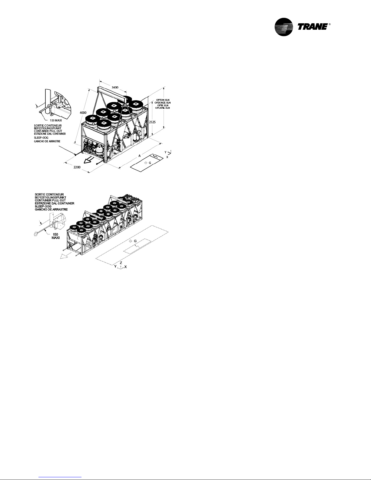
RLC-SVX19E-GB
45
Installation Requirements
Figure 2a – Lifting RTAF 090 – 205
Figure 2b – Lifting RTAF 250 – 450
Dimension and Weights
See lifting weight on the submittal on the unit for complete
information.
Center of Gravity
See instructions on lifting drawings available on request.
WARNING! Heavy Objects!
Ensure that all the lifting equipment used is properly
rated for weight of the unit being lifted. Each of the cables
(chains or slings), hooks, and shackles used to lift the
unit must be capable of supporting the entire weight
of unit. Lifting cables (chains or slings) may not be the
same length. Adjust as necessary for even unit lift. Other
lifting arrangements could cause equipment or property
damage. Failure to follow instructions above or properly
lift unit could result in unit dropping and possibly crushing
operator/technician which could result in death or serious
injury.
WARNING! Improper Unit Lift!
Test lift unit approximately 10 cm to verify proper center of
gravity lift point. To avoid dropping of unit, reposition lifting
point if unit is not level. Failure to properly lift unit could
result in unit dropping and possibly crushing operator/
technician which could result in death or serious injury and
possible equipment or property- only damage.
Clearances
When installing the unit, provide enough space around the
unit to allow the installation and maintenance personnel
unrestricted access to all service points.
Unobstructed flow of condenser air is essential to maintain
chiller capacity and operating efficiency. When determining
unit placement, give careful consideration to ensuring a
sufficient air flow across the condenser coils heat-transfer
surface.
In case of enclosure around the unit, the height of the
enclosure must not be higher than the unit itself. If the
enclosure is higher than the unit, restrictive airflow louvers
should be fitted to ensure fresh air supply.
Unit Isolation and Leveling
Provide a foundation with sufficient strength and mass
to support the unit operating weight (that is, including
completed piping, full operating charges of refrigerant and
oil, and water). Refer to unit operating weights. The unit
must be leveled within 5 mm over its length and width.
Use shims as necessary to level the unit. For additional
reduction of sound and vibration, install the optional
elastomeric isolators.
Sound consideration
The most effective form of acoustical isolation is to locate
the unit away from any sound sensitive area. Structurally
transmitted sound can be reduced by elastomeric vibration
eliminators. Spring isolators are not recommended. Consult
an acoustical engineer in critical sound applications.
For maximum isolation effect, isolate water lines and
electrical conduit. Rubber isolated piping hangers can be
used to reduce the sound transmitted through water piping.
To reduce sound transmitted through electrical conduit, use
flexible electrical conduit.
EU and Local Regulations codes on sound emissions should
always be considered. Since the environment in which a
sound source is located affects the sound pressure, unit
placement must be carefully evaluated.
Page 46

RLC-SVX19E-GB
46
Installation Requirements
Elastomeric Isolators Installation
(Optional)
Isolators are ready to install. Mountings have to
be placed on a rigid and level foundation. External
equipment should not transmit additional vibration to
the chiller. The position of elastomeric isolator and
weight per point are given in the Neoprene isolators
installation drawing which is supplied with the chiller.
Wrong placement along the unit may result in excessive
deflection.
1. Secure the isolators to the mounting surface
using the mounting slots in the isolator’s base
plate. Do NOT fully tighten the isolators mounting
bolts at this time. See the isolators submittals for
isolators location, maximum weights, and isolators
diagrams.
2. Align the mounting holes in the base of the unit
with the threaded positioning pins on the top of the
isolators.
3. Install the unit on the isolators and secure the
isolators to the unit with a nut. The maximum
isolators deflection should be 13 mm.
4. Level the unit carefully. Fully tighten the isolator
mounting bolts.
Figure 3 – Elastomeric Isolator
117.6
14.2
127 159
16
63.5
70
12.7
9.6
40.6
Isolator Pads Installation (Optional)
Isolators are ready to install. Mountings have to
be placed on a rigid and level foundation. External
equipment should not transmit additional vibration to
the chiller. The position of pads isolator is given in the
pad isolators installation or selection drawing which is
supplied with the chiller.
Figure 4 – Isolator pads
450
90
8
Page 47

RLC-SVX19E-GB
47
Dimensional Data
The dimensional data below are given for reference only. Dimensions details, dimensions of hydraulic connections,
electrical connections, isolator positioning, specific features for heat recovery and free cooling are included in
submittals and diagrams provided in documentation package.
Figure 5 – Units RTAF 090 to 205 SE HE XE
Operating weight (kg)
090 105 125 145 155 175 190 205
SN LN unit
SE 3295 3330 3510 3970 4240 4400 4820 4845
HE_XE 3595 3630 3810 4220 4485 4640 5075 5210
Hydraulic module DPSP
SE 3645 3690 3910 4410 4780 4945 5365 5390
HE_XE 3975 4020 4240 4660 5025 5180 5615 5750
Hydraulic module DPHP
SE 3730 3760 3955 4575 4840 4995 5420 5445
HE_XE 4055 4090 4285 4820 5090 5240 5680 5810
XLN unit
SE +80 +80 +80 +10 0 +10 0 +10 0 +120 +120
XE + 100 +10 0 +10 0 +120 +120 +120 +140 +140
Hydraulic module VPF SE-HE-XE +70
DPSP: Dual Pump Standard Pressure
DPHP: Dual Pump High Pressure
Important! Additional space is required to remove evaporator tubes.
For RTAF 090 to 245: 2.5 m in front of the unit (evaporator side).
Page 48

RLC-SVX19E-GB
48
Dimensional Data
Figure 6 – Units RTAF 090 to 245 HSE HSS
DPSP: Dual Pump Standard Pressure
DPHP: Dual Pump High Pressure
Important! Additional space is required to remove evaporator tubes.
For RTAF 090 to 245: 2.5 m in front of the unit (evaporator side).
Operating weight (kg)
090105 125145 155175 190205 245
HSS340034353615407543404610507051005205
HSE370037353915432045854850532554605460
HSS375037954015451548855160562056455755
HSE408041254345476051255390586560006000
HSS383538654060468049455210567557005810
HSE416041954390492551905450593060606060
HSS+80 +80+80 +100 +100 +100 +120 +120 +120
HSE+100+100 +100 +120 +120 +120 +140 +140 +140
+70
SN LN unit
Hydraulic module DPSP
Hydraulic module DPHP
XLN unit
Hydraulic module VPF
Page 49

RLC-SVX19E-GB
49
Dimensional Data
Figure 7 – RTAF 250-410 SE HE XE
Operating weight (kg)
250 280 310 350 380 410 450
SN-LN unit
HSS 6685 7275 7325 8700 9070 9425 -----
HSE 7005 7575 7945 9345 9650 9715 9715
Option XLN
HSS +140 +160 +160 +180 +200 +220 -----
HSE +160 +180 +200 +220 +240 +240 +240
Hydraulic Module DPSP
HSS 7354 8264 8314 9929 10299 10654 -----
HSE 7678 8564 8934 10 574 10879 10944 10944
Hydraulic Module DPHP
HSS 7379 8053 8103 ----- ----- ----- -----
HSE 7703 8353 8103 ----- ----- ----- -----
Hydraulic Module VPF HSS_HSE +70
Important! Additional space is required to remove evaporator tubes.
For RTAF sizes 250 to 450 : 4.5 meter in front of the unit (evaporator outlet side at the right of the electrical panel).
Page 50

RLC-SVX19E-GB
50
Dimensional Data
Figure 8 – RTAF 250-450 HSS HSE
Operating weight (kg)
250 280 310 350 380 410 450
SN LN unit
HSS 6685 7275 7325 8700 9070 9425 ----
HSE 7005 7575 7945 9345 9650 9715 9715
Hydraulic module
HSS +140 +160 +160 +180 +200 +220 ----
HSE +160 +180 +200 +220 +240 +240 +240
Important! Additional space is required to remove evaporator tubes.
For RTAF sizes 250 to 450 : 4.5 meter in front of the unit (evaporator outlet side at the right of the electrical panel).
Page 51

RLC-SVX19E-GB
51
Chilled Water Piping Recommendations
Drainage
A large capacity drain must be provided for water vessel
drain-down during shutdown or repair. The evaporator is
provided with drain connections. An air vent on top of the
evaporator water box prevents vacuum by removing air
from evaporator for complete drainage.
Water Treatment
In the evaporator the following material are in contact
with water:
• Water boxes are made of cast iron (GJL250 EN-code)
• Tube plates are made of steel (P265GH code)
• Tubes are made of copper
• Turbulators when present in evaporator tubes are made
of phosphorous brass.
When the unit is supplied with hydraulic module, the
following additional materials are in contact with water:
• Pump frame and connections are made of cast iron
• Water pipes are made of iron
• Pipe sealings are made of EPDM rubber (ethylene
propylene diene monomer rubber)
• Pump sealings are made of silicon carbide
• Strainer is made of stainless steel
Dirt, scale, products of corrosion, and other foreign
material will adversely affect heat transfer between the
water and system components. Foreign matter in the
chilled-water system can also increase pressure drop and
consequently, reduce water flow. Proper water treatment
must be determined locally, depending on the type of
system and local water characteristics.
Neither salt nor brackish water is recommended for use
in Trane air-cooled chillers. Use of either will lead to an
unpredictably shorter life cycle. Trane encourages the
employment of a reputable water treatment specialist,
familiar with local water conditions, to assist in this
determination and in the establishment of a proper water
treatment program.
CAUTION! If using an acidic commercial flushing
solution, construct a temporary bypass around the
unit to prevent damage to internal components of
the evaporator. Trane assumes no responsibility for
equipment failures which results from untreated or
improperly treated water or saline or brackish water.
If calcium chloride is used for water treatment, an
applicable corrosion inhibitor must also be used. Failure
to do so may result in damage to system components. Do
not use untreated or improperly treated water. Equipment
damage may occur.
Page 52

RLC-SVX19E-GB
52
Evaporator Piping
Evaporator water connections are grooved.
Thoroughly flush all water piping to the unit before
making the final piping connections to the unit.
Components and layout will vary slightly, depending on
the location of connections and the water sources.
An air vent is located on top of the evaporator at the
chiller water outlet. Be sure to provide additional air vents
at the highest points in the piping to remove air from the
chilled water system. Install necessary pressure gauges to
monitor the entering and leaving chilled water pressure.
Provide shut off valves in lines to the gauges to isolate
them from the system when they are not in use. Use
rubber vibration eliminators to prevent vibration
transmission through the water lines.
If desired, install thermometers in the lines to monitor
entering and leaving water line to control water flow
balance. Install shutoff valves on both the entering and
leaving water lines so that the evaporator can be isolated
for service.
CAUTION! The chilled-water connections to the
evaporator are to be “grooved pipe” type connections.
Do not attempt to weld these connections, because the
heat generated from welding can cause microscopic
and macroscopic fractures on the cast iron water boxes
that can lead to premature failure of the water box. An
optional grooved pipe stub and coupling is available for
welding on flanges.
To prevent damage to chilled-water components, do not
allow evaporator pressure (maximum working pressure)
to exceed 10 Bar. The maximum service pressure depends
on free cooling type and potential pump package option.
The value of max service pressure is indicated on unit
nameplate.
A pipe strainer must be installed in the entering water
line. Failure to do so can allow waterborne debris to enter
the evaporator.
Page 53

RLC-SVX19E-GB
53
Evaporator Piping
Evaporator Piping Components
Piping components include all devices and controls used to provide proper water system operation and unit
operating safety. A typical RTAF evaporator piping is shown below.
Figure 9 – Typical RTAF evaporator water piping
1 = Isolation valve
2 = Vibration isolators
3 = Evaporator – End view (2-pass)
4 = Evaporator Waterbox
5 = Vent
6 = Strainer
7 = Drain
Entering Chilled Water Piping
• Air vents to bleed the air from the system (to be placed
on the highest point)
• Water pressure gauges with shutoff valves
• Vibration eliminators
• Shutoff (isolation) valves
• Thermometers if desired (temperature readings
available on chiller controller display)
• Clean-out tees
• Pipe strainer
Pi = Pressure gauge
FT = Water Flow Switch
T1 = Evaporator Water Inlet Temperature Sensor
T2 = Evaporator Water Outlet Temperature Sensor
A = Isolate unit for initial water loop cleaning
B = Vent must be installed at the high point of the line
C = Drain must be installed at the low point of the line
Leaving Chilled Water Piping
• Air vents to bleed the air from the system (to be placed
on the highest point)
• Water pressure gauges with shut off valves
• Vibration eliminators
• Shutoff (isolation) valves
• Thermometers (temperature readings available on the
chiller controller display)
• Clean-out tees
• Balancing valve
• Flow Proving Device
1
1
2
2
6
7
5
3
4
1
1
A
A
B
7
C
Page 54

RLC-SVX19E-GB
54
Evaporator Piping
Drains
RTAF chillers are equipped with 2 drain connections with valves: one located on the input box and the other on the
back box of evaporator.
Figure 10 – Drain and vent position on evaporator
Figure 11 – Drain and air vent fitting location on the evaporator water side
In case of winter water drainage for freeze protection, it is mandatory to disconnect the evaporator’s heaters
to protect them from burning due to overheat. It is also mandatory to fulfill the drainage, using pressurized air,
and ensure that no water stay in the evaporator during winter season. This operation needs to be performed also
on unit just delivered by factory.
Page 55

RLC-SVX19E-GB
55
Evaporator Piping
Pressure Gauges
Install field-supplied pressure components as shown in
Figure 6. Locate pressure gauges or taps in a straight run
of pipe; avoid placing them near elbow (at least at 10 pipe
diameter from discontinuity).
To read manifold pressure gauges, open one valve and
close the other (depending on the side of the desired
reading), this eliminate errors resulting from differently
calibrated gauges installed at unmatched elevations.
Pressure Relief Valves
Install a water pressure relief valve in the evaporator inlet
piping between evaporator and the inlet shutoff valve.
Water vessels with close-coupled shutoff valves have
high potential for hydrostatic pressure buildup on a water
temperature increase. Refer to applicable local codes for
relief valve installation.
Evaporator Flow Switch
Specific connection and schematic wiring diagram
are shipped within the unit. Some piping and control
schemes, particularly those using a single water pump
for both chilled and hot water, must be analyzed to
determine how and/or if a flow sensing device will
provide the desired operation.
Flow Switch Installation – Typical Requirements
1. Mount the switch upright, with a minimum of 5 pipes
diameters of straight horizontal run on each side. Do
not install close to elbows, orifices, or valves. The
arrow on the switch must point in the direction of the
flow.
2. To prevent switch fluttering, remove all air from the
water system. Tracer UC800 provides a 6 second time
delay after a “loss-of-flow” diagnostic before shutting
the unit down. Contact a Trane service representative
if nuisance machine shutdowns persist.
3. Adjust the switch to open when water flow falls
below nominal values. Evaporator data is given
on the General Information Section. Flow Switch
contacts are closed on proof of water flow.
4. Install a pipe strainer in the entering evaporatorwater line to protect components.
CAUTION! Control voltage from the chiller to the flow
proving device is 110V AC.
Page 56

RLC-SVX19E-GB
56
Optional Integrated Pump Package
Installation – Mechanical
On chiller sizes 090, 105, 125 and 250 standard efficiency; the suction pipe is not installed on the pump flange for
shipping purpose. This operation will have to be done once the chiller is delivered on job site according to the
following figure. Fasteners and gaskets are fixed to the pipe assembly.
Figure 12 – Shipping arrangement and Operational arrangement
Unit size 090-125
Inlet pipe assembly
locaon for shipping
To be installed on
the pump flange
Unit size 250
The heater cable will be routed along the frame cross member to be connected to the heater terminal block located
inside the junction box according to the following figure.
Page 57

RLC-SVX19E-GB
57
Figure 13 – The junction box
Optional Integrated Pump Package
Page 58

RLC-SVX19E-GB
58
Optional Integrated Pump Package
Pump Curves
In the figures below are described Pump Curves with a combination of Standard Head - High Head with standard
tubes and turbulators inside the evaporator for the whole unit range, sizes 090 to 245 and sizes 250 to 450.
Figure 14 – Pump Curve - Sizes 090-245 - Standard Head - Standard Tube
Standard Tube - Standard Head
Page 59

RLC-SVX19E-GB
59
Optional Integrated Pump Package
Figure 15 – Pump Curve - Sizes 090-245 - High Head - Standard Tube
Standard Tube - High Head
0
50
100
150
200
250
300
350
400
0 5 10 15 20 25 30 35 40 45 50 55 60 65
Availab le Pressure (kPa)
Water flow r ates (l/ s)
1. RTAF 090 SE-HE-XE-H SS-HSE
2. RTAF 105 SE-HE-XE-H SS-HSE
3. RTAF 125 SE-HE-XE-H SS-HSE
4. RTAF 145 SE-HE-XE-H SS-HSE
5. RTAF 155 SE-HE-XE-H SS-HSE
6. RTAF 175 SE-HE-XE-H SS-HSE
7. RTAF 190 SE-HE-XE-H SS-HSE
8. RTAF 205 SE-HSS
9. RTAF 205 HE-XE-H SE /
245 HSE
1
2
3
4
5
6
7
8
9
Page 60
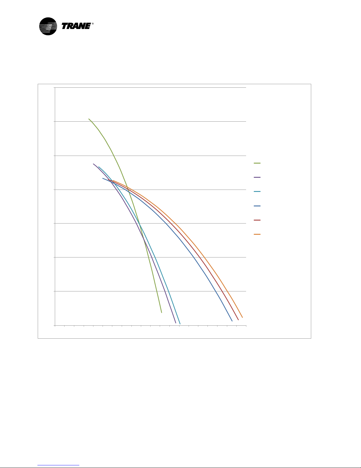
RLC-SVX19E-GB
60
Figure 16
–
Pump Curve - Sizes 250 - 450 - Standard Head - Standard Tubes
Standard Tube - Standard Head
0
50
100
150
200
250
300
350
0 5 10 15 20 25 30 35 40 45 50 55 60 65 70 75 80 85 90 95 100
Availab le Pressure (kPa)
Water flow r ates (l/ s)
1. RTAF 250 SE-HSS-HE-XE -HSE
2. RTAF 280 SE-HSS-HE-XE -HSE
3. RTAF 310 SE-HSS-HE-
XE-HSE
4. RTAF 350 SE-HSS-HE-XE -HSE
5. RTAF 380 SE-HSS-HE-XE -HSE
6. RTAF 410 SE-HSS-HE-XE -HSE
/RTAF 415 XE/ RTAF 450 HSE
1
2
3
4
5
6
Optional Integrated Pump Package
Page 61

RLC-SVX19E-GB
61
Optional Integrated Pump Package
Figure 17
– Pump Curve - Sizes 250 - 280 - 310 - High Head - Standard Tubes
(no high head for sizes 350 - 380 - 410 - 415 and 450)
Standard Tube - High Head
Page 62

RLC-SVX19E-GB
62
Figure 18 – Pump Curve - Sizes 090-245 - Standard Head - Tube with Turbulators
Tubulator Tube - Standard Head
0
50
100
150
200
250
0 5 10 15 20 25 30 35 40 45
Availab le Pressure (kPa)
Water flow r ates (l/ s)
1. RTAF 090 SE-HE-XE-H SS-HSE
2. RTAF 105 SE-HE-XE-H SS-HSE
3. RTAF 125 SE
-HE-XE-HSS-H SE
4. RTAF 145 SE-HE-XE-H SS-HSE
5. RTAF 155 SE-HE-XE-H SS-HSE
6. RTAF 175 SE-HE-XE-H SS-HSE
7. RTAF 190 SE-HE-XE-H SS-HSE
8. RTAF 205 SE-HSS
9. RTAF 205 HE-XE-H SE /
245 HSE
1
2
3
4
5
6-7
8
9
Optional Integrated Pump Package
Page 63

RLC-SVX19E-GB
63
Figure 19 – Pump Curve - Sizes 090-245 - High Head - Tube with Turbulators
Tubulator Tube - High Head
Optional Integrated Pump Package
Page 64

RLC-SVX19E-GB
64
Optional Integrated Pump Package
Figure 20 – Pump Curve - Sizes 250 - 450 - Standard Head - Tubes with Turbulators
Tubulator Tube - Standard Head
0
50
100
150
200
250
300
350
0 5 10 15 20 25 30 35 40 45 50 55 60 65 70 75 80 85 90
Availab le Pressure (kPa)
Water flow r ates (l/ s)
1. RTAF 250 SE-HSS-HE-XE -HSE
2. RTAF 280 SE-HSS-HE-XE -HSE
3. RTAF 310 SE-HSS-HE-XE -HSE
4. RTAF 350 SE-HSS-HE-XE -HSE
5. RTAF 380 SE-HSS-HE-XE -HSE
6. RTAF 410 SE-HSS-HE-XE -HSE
/RTAF 415 XE/ RTAF 450 HSE
1
2
3
4
5
6
Page 65

RLC-SVX19E-GB
65
Figure 21 – Pump Curve - Sizes 250 - 280 - 310 - High Head - Standard Tubes
(no high head for sizes 350 - 380 - 410 - 415 and 450)
Tubulator Tube - High Head
Optional Integrated Pump Package
Page 66

RLC-SVX19E-GB
66
Optional Integrated Pump Package
Figure 22 – Hydraulic module water chart
1 = Twin centrifugal pump
2 = Water strainer
3 = Balancing valve
4 = Drain valve
5 = Valve for pressure point
6 = Expansion tank
7 = Pressure relief valve
8 = Antifreeze protection
9 = Evaporator
Pi = Gauge
TT = Temperature sensor
Chiller can be ordered with an optional integrated
hydraulic module. In this case, chiller will be provided
with the following components factory mounted and
tested:
• Twin centrifugal water pump, Low pressure or High
pressure (option)
• Water strainer to protect the pump against impurities in
the circuit
• Expansion module with expansion vessel and pressure
relief valve sufficient to ensure the expansion of the
water loop ability
• Thermal insulation for antifreeze protection
• Balancing valve for equilibrate the flow of water circuit
• Drain valve
• Temperature sensor
Note: A pressure switch device to detect lack of water
is not included in the pump package. Installation of this
type of device is highly recommended to avoid sealing
damage due to operation of pump without enough water.
CHILLED WATER
5
Pi
1
23 4 4
5
6
7
9
TT
TT
8
88
8
8
45
5
Page 67

RLC-SVX19E-GB
67
Heat recovery option is made with a plate heat exchanger in series with the air-cooled condenser. This heat
exchanger benefits the discharge gas superheat as well as a part of the condensing gas heat to be transferred to hot
water system.
All Submittals, lifting diagrams, neoprene pads positioning and wiring diagrams have been supplied with the chiller
order.
PHR General data
PHR RTAF RTAF RTAF RTAF RTAF RTAF RTAF RTAF RTAF
090 105 125 145 155 175 190 205 245 (2)
Heating capacity (1)
Gross heating Capacity (1) (kW) 82 94 110 131 141 154 169 183 220
Condenser
Type Stainless steel Copper Brazed plate Heat exchanger
Circuit 1 BPHE
B3-095
28pl
B3-095
28pl
B3-095
28pl
B3-095
28pl
B3-095
40pl
B3-095
40pl
B3-095
40pl
B3-095
40pl
B3-095
40pl
Circuit 2 BPHE
B3-095
28pl
B3-095
28pl
B3-095
28pl
B3-095
28pl
B3-095
40pl
B3-095
40pl
B3-095
40pl
B3-095
40pl
B3-095
40pl
Nominal water connection
size (Grooved coupling)
(in) (mm)
2’’ - 50mm 2’’ - 50mm 2’’ - 50mm 2’’ - 50mm 2’’ - 50mm 2’’ - 50mm 2’’ - 50mm 2’’ - 50mm 2’’ - 50mm
Water content volume (l) 10.0 10.0 10.0 10.0 12.0 12.0 12.0 12.0 12.0
RTAF RTAF RTAF RTAF RTAF RTAF RTAF RTAF
250 280 310 350 380 410 415 450 (2)
Heating capacity (1)
Gross heating Capacity (1) (kW) 215 244 269 300 332 363 363 398
Condenser - Water Cooled (PHR)
Type Stainless steel Copper Brazed Plates Heat Exchanger
Circuit 1 BPHE
B3-095
70pl
B3-095
70pl
B3-095
70pl
B3-095
70pl
B3-095
70pl
B3-095
70pl
B3-095
70pl
B3-095
70pl
Circuit 2 BPHE
B3-095
40pl
B3-095
40pl
B3-095
40pl
B3-095
70pl
B3-095
70pl
B3-095
70pl
B3-095
70pl
B3-095
70pl
Nominal water connection
size (Grooved coupling)
(in) -
(mm)
2” - 50mm 2” - 50mm 2” - 50mm 2” - 50mm 2” - 50mm 2” - 50mm 2” - 50mm 2” - 50mm
Water content volume (l) 30 30 30 35 35 35 35 35
(1) Indicative performance at Evaporator water temperature : 12°C / 7°C - Condenser air temperature 35°C - Condenser water temperature 40°C/45°C .
For accurate value refer to OWU
(2) Variable speed compressor only
Figure 23 – Water pressure drop - heat recovery heat exchanger
1.00
10.00
100.00
1 10
Pressure drop (kPa)
Wate r flow (L/s)
1 = RTAF 90/105/125/145
2 = RTAF 155/175/190/205/245
3 = RTAF 250/280/310
4 = RTAF 350/380/410/415/450
1
2
3
4
Partial Heat Recovery
Page 68

RLC-SVX19E-GB
68
Total Heat Recovery
All submittals, Refrigerant schematics, lifting diagrams, neoprene pads positioning and wiring diagrams have been
supplied with the chiller order.
PHR General data
THR RTAF RTAF RTAF RTAF RTAF RTAF RTAF RTAF RTAF
090 105 125 145 155 175 190 205 245 (2)
Heating capacity (1)
Gross heating Capacity (1) (kW) 372 432 513 596 664 732 791 863 1045
Condenser
Type Stainless steel Copper Brazed plate Heat exchanger
Circuit 1 BPHE
B56N-W
112pl
B56N-W
112pl
B56N-W
112pl
B56N-W
112pl
B56N-W
176pl
B56N-W
176pl
B56N-W
176pl
B56N-W
176pl
B56N-W
176pl
Circuit 2 BPHE
B56N-W
112pl
B56N-W
112pl
B56N-W
112pl
B56N-W
112pl
B56N-W
176pl
B56N-W
176pl
B56N-W
176pl
B56N-W
176pl
B56N-W
176pl
Nominal water connection
size (Grooved coupling)
(in) (mm)
4'' -
100mm
4'' -
100mm
4'' -
100mm
4'' -
100mm
5'' -
125mm
5'' -
125mm
5'' -
125mm
5'' -
125mm
5'' -
125mm
Water content volume (l) TBD TBD TBD TBD TBD TBD TBD TBD TBD
Antifreeze Heater (W) 900.0 900.0 900.0 900.0 900.0 900.0 900.0 900.0 900.0
BPHE heaters (W) 132.0 132.0 132.0 132.0 132.0 132.0 132.0 132.0 132.0
RTAF RTAF RTAF RTAF RTAF RTAF RTAF RTAF
250 280 310 350 380 410 415 450 (2)
Heating capacity (1)
Gross heating Capacity (1) (kW) 1021 1152 1288 1440 1578 1717 1685 1893
Condenser - Water Cooled (PHR)
Type Stainless steel Copper Brazed Plates Heat Exchanger
Circuit 1 BPHE
B427L
318pl
B427L
318pl
B427L
318pl
B427L
318pl
B427L
318pl
B427L
318pl
B427L
318pl
B427L
318pl
Circuit 2 BPHE
B56N-W
176pl
B56N-W
176pl
B56N-W
176pl
B427L
318pl
B427L
318pl
B427L
318pl
B427L
318pl
B427L
318pl
Nominal water connection
size (Grooved coupling)
(in) -
(mm)
6" -
150mm
6" -
150mm
6" -
150mm
6" -
150mm
6" -
150mm
6" -
150mm
6" -
150mm
6" -
150mm
Water content volume (l) 200 200 200 230 230 230 230 230
Antifreeze Heater (W) 900 900 900 900 900 900 900 900
BPHE heaters (W) 165 165 165 200 200 200 200 200
(1) Indicative performance at Evaporator water temperature : 12°C / 7°C - Condenser air temperature 35°C - Condenser water temperature 40°C/45°C .
For accurate value refer to OWU
(2) Variable speed compressor only
2 versions:
- Digit 23=T Full equipment (BPHE + Water lines + 3-ways water valve + heaters + flow-switch + insulation)
- Digit 23=V Naked (BPHE + insulation)
- This type of unit remains an air-cooled chiller before modification into a Total Heat Recovery unit. Start up and Shut
down are always carried out in chiller mode. (freeze protection by standard tank)
- All Free cooling options exclude Total Heat Recovery and not developed for high ambient.
- Operating map : Maximum water temperature depends on compressor load and operating conditions. It may vary
from 30°C to 61°C. For details performance consult Order Write Up.
- Flow-switch : The flow-switch is fitted on water line to monitor a to low water flow through the Total Heat Recovery
heat Exchanger.
- Heaters are placed on water piping to heat the whole Total Heat Recovery system (water piping, water 3-ways valve,
BPHE).
- To protect the Total Heat Recovery circuit during winter or off mode, circuit must be filled by by glycol with at least a
concentration of 35%.
- Introduction of an expansion tank and safety valve is recommended on the water circuit.
- The water valve is a safety device to allow a limited water flow below 25°C of THR entering water. Above 25°C,
the 3-ways water valve is full open.
Page 69

RLC-SVX19E-GB
69
Total Heat Recovery
Figure 24 – THR pressure drop - Heat Exchanger Only
10
100
10 100
Pressure drop (kPa)
Wat er flow (L /s)
THR pressure drop - Only Heat Exchangers
1 = RTAF 090/105/125/145
2 = RTAF
155/175/190/205/245
3 = RTAF 250/280/310
4 = RTAF
350/380/410/415/450
2
1
3
4
Figure 25 – THR pressure drop - PHE=3 ways valve (full package)
10
100
10 100
Pressure drop (kPa)
Wat er flow (L /s)
THR pressure drop -BPHE + 3-ways valve + Water piping
1 = RTAF 090/105/125/145
2 = RTAF
155/175/190/205/245
3 = RTAF 250/280/310
4 = RTAF
350/380/410/415/450
1
2
3
4
Page 70

RLC-SVX19E-GB
70
Optional Free-Cooling
Table 19 – General data for free cooling option
RTAF RTAF RTAF RTAF RTAF RTAF RTAF RTAF RTAF
090 105 125 145 155 175 190 205 245
General
Heat-Exchanger Type Aluminum heat exchanger
Fan type (1) (SE-SN/HE-SN/HE-LN) AC AC AC AC AC AC AC AC N/A
Power per Motor (kW) 1.79 1.79 1.79 1.79 1.79 1.78 1.79 1.78 N/A
Motor RPM (rpm) 932 932 932 932 932 932 932 932 N/A
Fan type (2) SE-LN/XE-SN/XE-LN/HSS-SN/
HSS-LN/HSE-SN/HSE-LN
EC EC EC EC EC EC EC EC EC
Power per Motor (kW) 1.47 1.47 1.47 1.47 1.47 1.47 1.47 1.47 1.48
Motor RPM (rpm) 910 910 910 910 910 910 910 910 910
Fan type (3) SE-XLN/XE-XLN/HSS-SN/
HSS-XLN/HSE-XLN
ECXLN ECXLN ECXLN ECXLN ECXLN ECXLN ECXLN ECXLN ECXLN
Power per Motor (kW) 1.21 1.21 1.21 1.21 1.21 1.21 1.21 1.21 1.22
Motor RPM (rpm) 860 860 860 860 860 860 860 860 860
Input water connection size
(Grooved coupling)
(in) (DN)
4'' - 100 4" - 100 5" - 125 5" - 125 5" - 125 6" - 150 6" - 150 6" - 150 6" - 150
Output water connection size
(Grooved coupling)
(in) (DN)
4'' - 100 4" - 100 5" - 125 5" - 125 5" - 125 6" - 150 6" - 150 6" - 150 6" - 150
Direct Free Cooling Option (4)
Total Free Cooling Option
Coils quantity SE-SN/SE-LN/SE-XLN/
HSS-SN/HSS-LN/HSS-XLN (5)
# 7 7 7 9 9 9 11 11 N/A
Coils quantity HE-SN/HE-LN/XE-SN/XE-LN/
XE-XLN/HSE-SN/HSE-LN/HSE-XLN (6)
# 9 9 9 11 11 11 13 13 13
Summer nominal water ow (L/s) 15.8 18.4 21.4 25.6 27.5 30.4 33.4 36.0 42.2
Summer unit pressure drop (kPa) 74 88 100 82 90 95 115 117 159
Winter unit pressure drop (kPa) 143 165 187 182 197 204 204 209 247
Free Cooling weight (5) (kg) 502 502 502 648 653 694 782 779 N/A
Additional water content (without Evap.) (5) (L) 183 183 185 231 231 262 301 301 N/A
Free Cooling weight (6) (kg) 607 607 655 742 742 782 862 869 869
Additional water content (without Evap.) (6) (L) 223 223 231 270 270 301 338 338 338
Partial Free Cooling type
Coils quantity # 4 4 4 6 6 6 6 6 6
Summer nominal water ow (L/s) 16.1 18.6 21.6 26.0 28.0 30.8 33.8 36.6 43.1
Summer unit pressure drop (kPa) 75 89 76 85 92 97 117 119 166
Winter unit pressure drop (kPa) 132 150 165 149 159 167 191 196 244
Additional Free Cooling weight
(without water) (5)
(kg) 393 393 395 548 548 584 580 580 N/A
Additional water content (without Evap.) (5) (L) 134 134 135 183 183 216 214 214 N/A
Additional Free Cooling weight
(without water) (6)
(kg) 397 397 435 540 544 580 577 577 577
Additional water content (without Evap.) (6) (L) 137 137 140 181 181 214 218 218 218
Glycol Free Option
Total Free Cooling type
Coils quantity (5) # 7 7 7 9 9 9 11 11 N/A
Coils quantity (6) # 9 9 9 11 11 11 13 13 13
Summer nominal water ow (L/s) 14.8 17.2 20.1 23.9 25.7 28.3 31.1 33.6 39.2
Summer & Winter unit pressure drop (kPa) 63.9 74.5 79.9 77.9 84.4 89.3 90.4 90.1 117.3
Glycol Pump Max Power input (kW) (kW) 5.5 5.5 11 11 11 11 11 11 11
Glycol Pump Max Amps @ 110 V (A) 10.2
10.2 20.5 20.5 20.5 20.5 20.5 20.5 20.5
Freeze protection - Max Power input kW 0.72 0.72 0.72 0.9 0.9 0.9 0.9 1.02 1.02
Freeze protection - Max Amps A 1.8 1.8 1.8 2.25 2.25 2.25 2.25 2.55 2.55
Additional Free Cooling weight
(without water) (5)
(kg) 1032 1032 1069 1320 1307 1326 1467 1473 N/A
Additional Free Cooling weight
(without water) (6)
(kg) 1125 1125 1227 1395 1395 1414 1561 1561 1561
Additional water content (without Evap.) (5) (L) 69 69 88 109 109 111 126 126 N/A
Additional water content (without Evap.) (6) (L) 69 69 88 109 109 111 126 126 126
Glycol content (5) (L) 238 238 238 304 304 306 360 360 N/A
Glycol content (6) (L) 279 279 283 342 342 345 396 396 396
Additional baseframe length (5) (m) / / / / / / / / /
Additional baseframe length (6) (m) / / / / / / / / /
Page 71

RLC-SVX19E-GB
71
Optional Free-Cooling
RTAF RTAF RTAF RTAF RTAF RTAF RTAF RTAF RTAF
090 105 125 145 155 175 190 205 245
Partial Free Cooling type
Coils quantity (5) # 4 4 4 6 6 6 6 6 N/A
Coils quantity (6) # 4 4 4 6 6 6 6 6 6
Summer nominal water ow (L/s) 15.1 17.5 20.3 24.3 26.1 28.7 31.5 34.2 40.0
Summer & Winter unit pressure drop (kPa) 51 57 58 82 88 65 77 75 98
Glycol Pump Max Power input (kW) (kW) 4.0 4.0 4.0 4.0 4.0 5.5 5.5 5.5 5.5
Glycol Pump Max Amps @ 110 V (A) 7.8 7.8 7.8 7.8 7.8 10.2 10.2 10.2 10.2
Freeze protection - Max Power input kW 0.66 0.66 0.66 0.66 0.66 0.72 0.72 0.72 0.72
Freeze protection - Max Amps A 1.65 1.65 1.65 1.65 1.65 1.80 1.80 1.80 1.8
Additional Free Cooling weight
(without water) (5)
(kg) 777 777 789 928 928 1027 1023 1023 N/A
Additional Free Cooling weight
(without water) (6)
(kg) 785 785 801 918 924 1023 1019 1019 1019
Additional water content (without Evap.) (5) (L) 54 54 73 73 73 90 90 90 N/A
Additional water content (without Evap.) (6) (L) 785 785 801 918 924 1023 1019 1019 1019
Glycol content (5) (L) 175 175 173 219 219 239 238 238 N/A
Glycol content (6) (L) 279 279 283 342 342 345 396 396 396
Additional baseframe length (5) (m) 1.125 1.125 1.125 / / / / / N/A
Additional baseframe length (6) (m) / / / / / / / / /
(1) SE-SN/HE-SN/HE-LN
(2) SE-LN/XE-SN/XE-LN/HSS-SN/HSS-LN/HSE-SN/HSE-LN
(3) SE-XLN/XE-XLN/HSS-SN/HSS-XLN/HSE-XLN
(4) Max Speed - range is 60% to 100% of max speed
(5) SE-SN/SE-LN/SE-XLN/HSS-SN/HSS-LN/HSS-XLN
(6) HE-SN/HE-LN/XE-SN/XE-LN/XE-XLN/HSE-SN/HSE-LN/HSE-XLN
Table 19 – General data for free cooling option (continued)
Page 72

RLC-SVX19E-GB
72
Optional Free-Cooling
Table 19 – General data for free cooling option (continued)
RTAF RTAF RTAF RTAF RTAF RTAF RTAF RTAF
250 (4) 280 310 350 380 410 415 450
General
Heat-Exchanger Type Aluminum heat exchanger
Fan type (1) (SE-SN/HE-SN/HE-LN) AC AC AC AC AC AC N/A N/A
Power per Motor (kW) 1.78 1.79 1.78 1.79 1.79 1.79 N/A N/A
Motor RPM (rpm) 932 932 932 932 932 932 N/A N/A
Fan type (2) SE-LN/XE-SN/XE-LN/HSS-SN/HSS-LN/
HSE-SN/HSE-LN
EC EC EC EC EC EC EC EC
Power per Motor (kW) 1.47 1.47 1.47 1.47 1.47 1.47 2.04 2.04
Motor RPM (rpm) 910 910 910 910 910 910 1020 1020
Fan type (3) SE-XLN/XE-XLN/HSS-SN/HSS-XLN/HSEXLN
ECXLN ECXLN ECXLN ECXLN ECXLN ECXLN N/A ECXLN
Power per Motor (kW) 1.21 1.21 1.21 1.21 1.21 1.21 N/A 1.21
Motor RPM (rpm) 860 860 860 860 860 860 N/A 860
Input water connection size (Grooved coupling)
(in) -
(DN)
6" - 150 6" - 150 6" - 150 8" - 200 8" - 200 8" - 200 8" - 200 N/A
Output water connection size (Grooved coupling)
(in) -
(DN)
6" - 150 6" - 150 6" - 150 8" - 200 8" - 200 8" - 200 8" - 200 N/A
Direct Free Cooling Option
Total Free Cooling Option
Coils quantity SE-SN/SE-LN/SE-XLN/HSS-SN/HSS-LN/
HSS-XLN (6)
# 14 16 16 18 20 22 N/A N/A
Coils quantity HE-SN/HE-LN/XE-SN/XE-LN/XE-XLN/
HSE-SN/HSE-LN/HSE-XLN (7)
# 16 18 20 22 24 24 24 24
Summer nominal water ow (L/s) 42.0 47.6 52.7 58.6 64.8 70.1 72.0 76.0
Summer unit pressure drop (kPa) 93 106 118 98 109 119 123 142
Winter unit pressure drop (kPa) 207 215 229 205 210 219 220 240
Free Cooling weight (6) (kg) 1090 1239 1373 1425 1522 1629 N/A N/A
Additional water content (without Evap.) (6) (L) 602 663 663 765 829 892 N/A N/A
Free Cooling weight (7) (kg) 1239 1350 1596 1627 1757 1760 1760 1760
Additional water content (without Evap.) (7) (L) 663 726 787 892 956 956 956 956
Partial Free Cooling type
Coils quantity # 8 8 10 10 10 12 12 12
Summer nominal water ow (L/s) 42.5 48.0 53.3 59.9 65.9 71.5 72.8 77.6
Summer unit pressure drop (kPa) 94.2 107.2 119.5 101.0 111.9 122.9 124.4 148.1
Winter unit pressure drop (kPa) 180.5 201.7 184.4 204.6 224.3 209.1 215.3 236.0
Additional Free Cooling weight (without water) (6) (kg) 786 807 1084 993 1049 1086 N/A N/A
Additional water content (without Evap.) (6) (L) 413 416 479 518 532 578 N/A N/A
Additional Free Cooling weight (without water) (7) (kg) 807 804 1081 993 1049 1112 1112 1112
Additional water content (without Evap.) (7) (L) 416 413 476 518 532 582 582 582
Free Cooling Glycol Free Option
Total Free Cooling type
Coils quantity (6) # N/A 16 16 18 20 22 N/A N/A
Coils quantity (7) # 16 18 20 22 24 24 24 24
Summer nominal water ow (L/s) 39.7 44.4 49.2 54.7 60.5 65.4 67.2 70.7
Summer & Winter unit pressure drop (kPa) 77 84 92 101 98 107 112 124
Glycol Pump Max Power input (kW) (kW) 22 22 22 22 22 22 22 22
Glycol Pump Max Amps @ 110 V (A) 38 38 38 38 38 38 38 38
Freeze protection - Max Power input kW 1.8 1.8 1.8 1.8 1.8 2.04 2.04 2.04
Freeze protection - Max Amps A 4.5 4.5 4.5 4.5 4.5 5.1 5.1 5.1
Additional Free Cooling weight (without water) (6) (kg) N/A 2354 2354 2541 2752 2869 N/A N/A
Additional Free Cooling weight (without water) (7) (kg) 2354
2475 2595 2762 3009 3013 3013 3013
Additional water content (without Evap.) (6) (L) N/A 245 245 281 311 311 N/A N/A
Additional water content (without Evap.) (7) (L) 2354 2475 2595 2762 3009 3013 311 311
Glycol content (6) (L) N/A 765 765 825 918 982 N/A N/A
Glycol content (7) (L) 765 828 888 952 1045 1045 1045 1045
Additional baseframe length (6) (m) N/A 1.125 1.125 1.125 1.125 1.125 N/A N/A
Additional baseframe length (7) (m) 1.125 1.125 / 1.125 / / / /
Page 73

RLC-SVX19E-GB
73
Optional Free-Cooling
RTAF RTAF RTAF RTAF RTAF RTAF RTAF RTAF
250 (4) 280 310 350 380 410 415 450
Partial Free Cooling type (11)
Coils quantity (6) # N/A 8 10 10 10 12 N/A N/A
Coils quantity (7) # 8 8 10 10 10 12 12 12
Summer nominal water ow (L/s) 40.2 44.8 49.8 55.9 61.6 66.8 68.0 72.2
Summer & Winter unit pressure drop (kPa) 96 78 85 80 87 94 98 109
Glycol Pump Max Power input (kW) (kW) 11.0 11.0 11.0 11.0 11.0 11.0 11.0 11.0
Glycol Pump Max Amps @ 110 V (A) 20.5 20.5 20.5 20.5 20.5 20.5 20.5 20.5
Freeze protection - Max Power input kW 1.32 1.32 1.32 1.44 1.44 1.44 1.44 1.44
Freeze protection - Max Amps A 3.30 3.30 3.30 3.60 3.60 3.60 3.60 3.60
Additional Free Cooling weight (without water) (6) (kg) N/A 1422 1551 1675 1736 1775 N/A N/A
Additional Free Cooling weight (without water) (7) (kg) 1348 1419 1547 1675 1736 1803 1803 1803
Additional water content (without Evap.) (6) (L) N/A 132 132 182 182 182 N/A N/A
Additional water content (without Evap.) (7) (L) 111 132 132 182 182 182 182 182
Glycol content (6) (L) N/A 496 560 575 589 635 N/A N/A
Glycol content (7) (L) 475 493 556 575 589 639 639 639
Additional baseframe length (6) (m) N/A 1.125 1.125 1.125 1.125 1.125 N/A N/A
Additional baseframe length (7) (m) 1.125 1.125 / 1.125 / / / /
(1) SE-SN/HE-SN/HE-LN
(2) SE-LN/XE-SN/XE-LN/HSS-SN/HSS-LN/HSE-SN/HSE-LN
(3) SE-XLN/XE-XLN/HSS-SN/HSS-XLN/HSE-XLN
(4) Option is not define for size 250 option SE-SN/SE-LN/SE-XLN/HSS-LN/HSS-XLN
(5) Max Speed - range is 60% to 100% of max speed
(6) SE-SN/SE-LN/SE-XLN/HSS-SN/HSS-LN/HSS-XLN
(7) HE-SN/HE-LN/XE-SN/XE-LN/XE-XLN/HSE-SN/HSE-LN/HSE-XLN
Table 19 – General data for free cooling option (continued)
Page 74

RLC-SVX19E-GB
74
Chiller integrated free-cooling operation mode
The power of chiller integrated free-cooling relies on the chiller control to maximize the use of free-cooling when
outdoor temperatures are favorable. The choice between compressor refrigeration and Free-Cooling refrigeration will
be made and activated depending on three temperature measurements:
• The ambient air temperature
• The evaporator entering and leaving temperature
• The chilled water set point
Free-cooling coils are fit in series with the evaporator, and a set of water regulation valves allows the coils to be bypassed when they are no longer needed due to outdoor temperatures which are favorable for free-cooling.
Three operating modes can be differentiated:
1. Summer operation or Compressor refrigeration mode
In this operation mode, ambient temperature is higher than the temperature of the fluid entering the evaporator.
Free-cooling is not activated, compressors are running, and control is done in function of the fan/compressor logic of
operation.
2. Mid-season operation or combined refrigeration + Free-cooling mode
In this operation mode, free-cooling will be enabled whenever the outdoor temperature is below the evaporator
entering water temperature. The operating logic is described below. The free-cooling system operates combined with
the mechanical compressor refrigeration. Most of the time, free-cooling will only partially cover the required cooling
duty. In other words, mechanical refrigeration will complete what has already been delivered by free-cooling.
3. Winter operation or Full free-cooling mode
Below a certain ambient temperature, and depending on the chilled water set point requested, the entire cooling
duty is delivered by the free-cooling system. Compressors do not operate, since the free-cooling coils will be able to
deliver the requested chilled water temperature. The regulation of the capacity is described in the next section. In this
mode, only fans are running.
General information
The chiller integrated free-cooling system fluid based consist in a set of “Macro-channels” or “Radiators” coils,
fit in the same frame than the MCHE condenser coils of the chiller refrigerant circuit. Free-cooling coils will be full
aluminum, flat radiator design type, with low air pressure drop to avoid fan performances degradation.
Free-cooling coils are fit in series with the evaporator, and a set of water regulation valves ensures the system to
reach the required free-cooling capacity.
Optional Free-Cooling
Page 75

RLC-SVX19E-GB
75
Figure 26 – Flow chart – Free-Cooling – Direct free cooling version
123
4
A
B
ITEM DESIGNATION
1 DRY COOLER COILS
2 WATER STRAINER
3 MODULATING VALVE
4 DRAIN VALVE
5 VALVE FOR PRESSURE POINT
6 SERVICE VALVE
7 PRESSURE RELIEF VALVE
8 ANTIFREEZE PROTECTION
9 EVAPORATOR
ITEM DESIGNATION
TT TEMPERATURE SENSOR
TT
TT
TT
24 4
55
4
7
1
9
3
3
4
6
8
Optional Free-Cooling
Page 76

RLC-SVX19E-GB
76
Figure 27 – Total and Partial Free-Cooling option
If there is a need to get a definition for partial heat recovery coil distribution, please contact the Trane Sales office.
Free-Cooling Enabling Conditions
To get the free cooling active, condition is to have unit in active cooling mode and that Outdoor temperature low
enough according to figure below.
The free cooling function is enabled when outdoor air temperature is below Active chilled water cooling set point
minus FC_offset.
A hysteresis should also apply to avoid short cycling of Free Cooling enabling logic. The Free Cooling offset is an
adjustable parameter to make free cooling active.
If free cooling function is enabled, free cooling becomes the 1st stage of cooling. Free cooling is the first stage to
engage for cooling capacity loading and the last stage to consider in capacity unloading.
In order to maximize tandem operation of free cooling with compressor the following logic is applied:
When unit is configured in “Partial free cooling”, when free cooling reaches its full capacity and there is a call for
compressor start, then the first circuit to start shall be circuit 2 (if available).This also means compressor balancing
function is disabled in these conditions.
Note: UC800 will not lockout compressor below free cooling change over point, but the compressor are lockout when
outdoor air is below “low ambient limit” set at -10°C. So FC will be the only source of cooling below -10°C.
Figure 28 – Free-cooling enabling conditions
Free Cooling Target Offset
Free Cooling Active
Free Cooling Inactive
Outdoor Air Temperature
Chiller Entering Water Temperature
1 deg. C
Free Cooling Activation Target
Optional Free-Cooling
Page 77

RLC-SVX19E-GB
77
Optional Free-Cooling
Figure 29 – Flow chart - Free cooling - Glycol free version
123
4
A
B
ITEM DESIGNATION
1 DRY COOLER COILS
2 PUMP
3 MODULATING VALVE
4 DRAIN VALVE
5 BPHE
6 EXPANSION TANK
7 PRESSURE RELIEF VALVE
8 ANTIFREEZE PROTECTION
9 EVAPORATOR
10
BYPASS MANUAL VALVE
(PARTIAL FREE COOLING ONLY)
ITEM DESIGNATION
TT TEMPERATURE SENSOR
TT TT
TT
4
4
7
1
9
3
4
TT
TT
8
2
6
5
8
10
Note: glycol free cooling chilled water setpoint should be in the range of [4°C - 20° C].
Page 78

RLC-SVX19E-GB
78
Note for installation
The maximum pressure of the Glycol side when unit is equipped with free cooling is 400 kPa for Glycol free option
or 600kPa for Direct free cooling except on evaporator side for glycol free 1000 kPa Refer to unit nameplate for rated
value.
Pump operation with Glycol free : it is requested to have a minimum water side pressure of 250 kPa to avoid
cavitation.
Glycol free option : To avoid component damage, a filter (1 mm mesh) must be supplied by the customer and
installed at the unit inlet.
All Free-cooling units must be freeze-protected with at least 30% Ethylene Glycol in the cooling loop circuit which is
the most convenient percentage in order to protect the unit against freezing.
Protection coverage with 30% Ethylene Glycol:
- Freezing point without burst effect = -13°C
- Freezing point with burst effect = -50°C.
Water can be trapped in BPHE and specific care must be taken to remove it completly from BPHE during off mode.
IMPORTANT – WATER QUALITY
Glycol or brine must be carefully chosen with the help of a reputable water treatment specialist. The additional
materials to the evaporator circuit are made with Carbon Steel, Copper, Zinc, Synthetic rubber, Aluminum AA3102,
AA3003, and AA4045. Water should be free from foreign solid particules.
All Submittal, lifting diagram, neoprene pads positioning and wiring diagrams have been supplied with chiller order.
Free cooler by-pass valve adjustment
For intervention on free cooler by-pass valve it is recommended to consult the valve service literature.
For every new referencing of the motor end travel, an adaptation of the motor should be done by pushing button 2
To change the bypass percentage follows below procedure:
− No tuning is needed on free cooling valve which always stays on full opening/closure.
− For bypass valve Belimo, minimum opening can be adjusted by pushing the release button (4) and by
turning handle 5 to 50% opening for instance (45°)
Optional Free-Cooling
Page 79

RLC-SVX19E-GB
79
Optional Free-Cooling
With a Phillips screwdriver, move the end of travel. Fix it to always keep an opening between 100% and the minimum
desired (50%) in example below.
If the minimum opening is modified after the first powering, motor re-calibration is needed to validate the new
operating range. When motor is powered, push green led button (2). Motor memorizes the new reference of end of
travel position on its signal (2…10 VDC)
Page 80

RLC-SVX19E-GB
80
Water Pressure Drops - Coils
The free cooling water pressure drops given in charts below (coil + valve) should be added to evaporator pressure
drop to get full unit pressure drop.
Figure 30 – Water pressure drop - Partial Free-Cooling - Sizes 090-245
10
100
1000
1 10 100
Pressure drop (kPa)
Water flow r ates (l/ s)
A. RTAF 090 SE, H SS
B. RTAF 090 HE, XE, HSE
C. R TAF 10 5 SE, HSS
D. RTAF 105 HE, XE, HSE
E. RTAF 12 5 SE, HSS
F. RTAF 125 HE, XE, HSE
G. RTAF 145 SE, H SS
H. RTAF 145 HE, XE, HSE
I. RTAF 155 SE, H SS
J. RTAF 155 HE, XE, HSE
K. RTAF 175 SE, H SS
L. RTAF 175 HE, XE, HSE
M. R TAF 19 0 SE, HSS
N. RTAF 190 HE, XE, HSE
O. R TAF 20 5 SE, HSS
P. RTAF 205 HE , XE, HSE
RTAF 245 HSE
A B C D E F
G H I J K L M N O P
Optional Free-Cooling
Page 81

RLC-SVX19E-GB
81
Figure 31 – Water pressure drop -Partial Free-Cooling - Direct Free Cooling version - Sizes 250-450
10
100
1000
10 100 1000
Pressure drop (kPa)
Water flow rates (l/s)
Paral Free Cooling
A. RTAF 250 SE, HSS
B. RTAF 250 HE, XE, HSE
C. RTAF 280 SE, HSS
D. RTAF 280 HE, XE, HSE
E. RTAF 310 SE, HSS
F. RTAF 310 HE, XE, HSE
I. RTAF 380 SE, HSS
J. RTAF 380 HE, XE, HSE
K. RTAF 410 SE, HSS
L. RTAF 410 HE, XE, HSE / RTAF 415 XE
RTAF 450 HSE
A-B
I-J
-
E-F
Optional Free-Cooling
Page 82

RLC-SVX19E-GB
82
Figure 32 – Water pressure drop - Total Free Cooling - Direct Free cooling version - Sizes 090 -245
10
100
1000
10 100 1000
Pressure drop (kPa)
Water flow rates (l/s)
Total Free Cooling
A. RTAF 250 SE, HSS
B. RTAF 250 HE, XE, HSE
C. RTAF 280 SE, HSS
D. RTAF 280 HE, XE, HSE
E. RTAF 310 SE, HSS
F. RTAF 310 HE, XE, HSE
G. RTAF 350 SE, HSS
H. RTAF 350 HE, XE, HSE
I. RTAF 380 SE, HSS
J. RTAF 380 HE, XE, HSE
K. RTAF 410 SE, HSS
L. RTAF 410 HE, XE, HSE / RTAF 415 XE
RTAF 450 HSE
A
H
B-C -E
D
F
I
K
J
L
Optional Free-Cooling
Page 83

RLC-SVX19E-GB
83
Figure 33 – Water pressure drop - Total Free Cooling - Direct Free Cooling Version- Sizes 250-450
10
100
1000
10 100 1000
Pressure drop (kPa)
Water flow ra tes (l/s)
A. RTAF 250 SE, HSS
B. RTAF 250 HE, XE, HSE
C. RTAF 280 SE , HSS
D. RTAF 280 HE, XE, HSE
E. RTAF 310 SE, HSS
F. R TAF 310 HE, XE, HSE
G. RTAF 350 SE, HSS
H. RTAF 350 HE, XE, HSE
I. RTAF 380 SE, HSS
J. RTAF 380 HE, XE, HSE
K. RTAF 410 SE, HSS
L. RTAF 410 HE, XE, HSE
RTAF 450 HSE
A
H
B-C -E
D
F
I
K
J
L
Optional Free-Cooling
Page 84

RLC-SVX19E-GB
84
Figure 34 – Water Pressure Drop - Glycol Free - Partial Free Cooling - Sizes 90-245
10
100
1000
11
01
00
Pressure drop (kPa)
Water flow rates (l/s)
Paral Free Cooling
A. RTAF 090
B. RTAF 105
C. RTAF 125
D. RTAF 145
E. RTAF 155
F. RTAF 175
G. RTAF 190
H. RTAF 205
A-B -C -D -E
F -G -H
Optional Free-Cooling
Page 85

RLC-SVX19E-GB
85
Figure 35 – Water Pressure Drop - Glycol Free - Total Free Cooling - Sizes 90-245
1
10
100
1000
11
01
00
Pressure drop (kPa)
Water flow rates (l/s)
Total Free Cooling
A. RTAF 090
B. RTAF 105
C. RTAF 125
D. RTAF 145
E. RTAF 155
F. RTAF 175
G. RTAF 190
H. RTAF 205
A -B-C
D -E
-
F
G
-H
Optional Free-Cooling
Page 86

RLC-SVX19E-GB
86
Figure 36 – Water Pressure Drop - Glycol Free - Partial Free Cooling - Sizes 250- 415
10
100
1000
10 10
01
000
Pressure drop (kPa)
Water flow rates (l/s)
Paral Free Cooling
A. RTAF 250
B. RTAF 280
C. RTAF 310
D. RTAF 350
E. RTAF 380
F. RTAF 410
D -E -F
B
C
A
Optional Free-Cooling
Page 87

RLC-SVX19E-GB
87
Figure 37 – Water Pressure Drop - Glycol Free - Total Free Cooling - Sizes 250-415
10
100
1000
10 100 1000
Pressure drop (kPa)
Water flow rates (l/s )
Total Free Cooling
A. RTAF 250
B. RTAF 280
C. RTAF 310
D. RTAF 350
E. RTAF 380
F. RTAF 410
A -B -C -D
E -F
Optional Free-Cooling
Page 88

RLC-SVX19E-GB
88
Figure 38a – Evaporator water pressure drop with standard tubes - Sizes 090-245
1
10
100
1000
11
01
00
Pressure drop (kPa)
Water flow rates (l/s)
1. RTAF 090 SE-HE-XE-HSS-HSE
2. RTAF 105 SE-HE-XE-HSS-HSE
3. RTAF 125 SE-HE-XE-HSS-HSE /
RTAF 145 SE-HE-XE-HSS-HSE
4. RTAF 155 SE-HE-XE-HSS-HSE
5. RTAF 175 SE-HE-XE-HSS-HSE /
RTAF 190 SE-HE-XE-HSS-HSE
6. RTAF 205 SE-HSS
7. RTAF 205 HE-XE-HSE /
245 HE-XE-HSE
1
2
3
4
5
6 7
Evaporator Waterside
Page 89

RLC-SVX19E-GB
89
Figure 38b – Evaporator water pressure drop with standard tubes - Sizes 250-450 (continued)
1
10
100
1000
110100 1000
Pressure drop (kPa)
Water flow rates (l/s)
1. RTAF 250 SE-HSS-HE-XE-HSE
2. RTAF 280 SE-HSS-HE-XE-HSE
3. RTAF 310 SE-HSS-HE-XE-HSE
4. RTAF 350 SE-HSS-HE-XE-HSE
5. RTAF 380 SE-HSS-HE-XE-HSE
6. RTAF 410 SE-HSS-HE-XE-HSE /
415 XE/ RTAF 450 HSE
1
2
3
4
5
6
Evaporator Waterside
Page 90

RLC-SVX19E-GB
90
Figure 39a – Evaporator water pressure drop with Turbulators - Sizes 090-245
1
10
100
1000
11
01
00
Pressure drop (kPa)
Water flow rates (l/s)
1. RTAF 090 SE-HE-XE-HSS-HSE
2. RTAF 105 SE-HE-XE-HSS-HSE
3. RTAF 125 SE-HE-XE-HSS-HSE /
RTAF 145 SE-HE-XE-HSS-HSE
4. RTAF 155 SE-HE-XE-HSS-HSE
5. RTAF 175 SE-HE-XE-HSS-HSE /
RTAF 190 SE-HE-XE-HSS-HSE
6. RTAF 205 SE-HSS
7. RTAF 205 HE-XE-HSE /
245 HE-XE-HSE
1
2
3
4
5
6
7
Evaporator Waterside
Page 91

RLC-SVX19E-GB
91
Figure 39b – Evaporator water pressure drop with Turbulators - Sizes 250-450 (continued)
1
10
100
1000
110100 1000
Pressure drop (kPa)
Water flow rates (l/s)
1. RTAF 250 SE-HSS-HE-XE-HSE
2. RTAF 280 SE-HSS-HE-XE-HSE
3. RTAF 310 SE-HSS-HE-XE-HSE
4. RTAF 350 SE-HSS-HE-XE-HSE
5. RTAF 380 SE-HSS-HE-XE-HSE
6. RTAF 410 SE-HSS-HE-XE-HSE /
415 XE/ RTAF 450 HSE
1
2
3
4
5
6
Evaporator Waterside
Page 92

RLC-SVX19E-GB
92
Freeze Protection
Depending on the ambient temperature the unit may be
exposed to freeze, there are multiple options for freeze
protection. They are listed in order of highest ambient
(least freeze protection) to the lowest ambient (most
freeze protection).
For all chiller running with water under cold ambient
temperature (below 0°C), it is extremely important to
keep full water flow in the evaporator for an extended
time after last compressor stops. This will protect
evaporator tube from freezing by refrigerant migration.
This is why evaporator water pump output relay must
be used to control the chilled water pump. This is not
mandatory if glycol is used with protection down to
lowest ambient expected.
1. Water pump and heaters
a. Heaters are factory installed on water boxes and
evaporator shell. They will protect it from freezing
in ambient temperatures down to -20°C.Heaters are
installed on the water piping and on the pumps of
units equipped with hydraulic module.
b. Install heat tape on all water piping, pumps, and other
components that may be damaged if exposed to
freezing temperatures. Heat tape must be designed
for low ambient temperature applications. Heat tape
selection should be based on the lowest expected
ambient temperature.
c. Tracer™ UC800 controller can start the pump(s) when
freezing conditions are detected. For this option the
pumps must be controlled by the RTAF unit and this
function validated on the chiller controller.
d. Water circuit valves need to stay open at all times.
Note: Water pump control and heater combination will
protect the evaporator down to any ambient temperature
provided power is available to the pump and the UC800
controller. This option will NOT protect the evaporator
in the event of power failure to the chiller unless backup
power is supplied to the necessary components.
Note: When no chiller operation is possible and the pump
is already off, UC800 pump control function for freeze
protection will command the pump to turn on:
•ON if the average of the evaporator entering water
temperature, evaporator leaving temperature, and the
evaporator refrigerant pool temperature is less than
Low Evaporator Refrigerant Temperature Cutout (LERTC)
+ 2.2°C for a period of time
•OFF again if the evaporator refrigerant pool temperature
rise above LERTC + 3.3°C for a period of time
Note: The period of time referenced for ON and OFF
conditions above described is dependent on past running
conditions and present temperature measured.
•ON if entering OR leaving water temperature < LWTC
for 16.2°C-sec
•OFF again if water temperature > LWTC for 30 min
OR
2. Freeze inhibitor
a. Freeze protection can be accomplished by adding
sufficient glycol to protect against freezing down to the
lowest ambient expected.
b. See “evaporator glycol requirement” section for
guidance on determining the glycol concentration.
Note: Use of glycol type antifreeze reduces the cooling
capacity of the unit and must be considered in the design
of the system specifications.
OR
3. Drain water circuit
For ambient temperatures below -20°C and for those
installation not including either option 1 or 2 above
described
a. Shut off power supply to unit and to all heaters.
b. Purge the water circuit
c. Blow out the evaporator to ensure that no liquid is left
inside the evaporator and the water lines. Drain the
pump.
CAUTION! Evaporator damage!
If insufficient concentration or no glycol is used, the
evaporator water pumps must be controlled by the
UC800 to avoid severe damage to the evaporator due
to freezing. A power loss of 15 minutes during freezing
can damage the evaporator. It is the responsibility of the
installing contractor and/or the customer to ensure that a
pump will start when called upon by the chiller controls.
Please consult the table named “Recommended Low
Evaporator Refrigerant Cutout (LRTC) and % Glycol for
RTAF chillers”.
With factory-fitted disconnect switch option, evaporator
trace heating is taken from the live side of the isolator.
As a consequence, the heaters are energized as long as
the main switch is closed. Supply voltage to the heating
tapes is 400V.
The warranty will be void, in case of freezing due to the
lack of use of either of these protections.
Evaporator Waterside
Page 93

RLC-SVX19E-GB
93
Evaporator Waterside (not for free cooling version)
Evaporator Glycol Requirement
Table 20 – Leaving water temperature cutout & glycol mass percent recommended for RTAF chillers with
Standard tubes
Ethylene Glycol
Unit type HE/XE/HSE Units
∆T evaporator
coolant (K)
2 3 4 5 6 7 8 2 3 4 5 6 7 8
LWT (°C)
LWTC
(°C)
%wt
Glycol
%wt
Glycol
%wt
Glycol
%wt
Glycol
%wt
Glycol
%wt
Glycol
%wt
Glycol
%wt
Glycol
%wt
Glycol
%wt
Glycol
%wt
Glycol
%wt
Glycol
%wt
Glycol
%wt
Glycol
4 1.2 - 4 4 4 4 4 5 13 4 4 4 4 4 5
2 -0.8 - 8 8 9 10 12 - 18 8 8 9 10 12 -
0 -2.8 13 13 13 15 19 - - 22 13 13 15 19 - -
-2 -4.8 18 18 19 - - - - 24 18 19 - - - -
-4 -6.8 22 22 - - - - - 25 22 - - - - -
-5 -7.8 24 25 - - - - - 27 25 - - - - -
-6 -8.8 25 29 - - - - - 29 29 - - - - -
-7 -9.8 27 - - - - - - 31 - - - - - -
-8 -10.8 29 - - - - - - - - - - - - -
-9 -11.8 31 - - - - - - - - - - - - -
-10 -12.8 - - - - - - - - - - - - - -
-11 -13.8 - - - - - - - - - - - - - -
-12 -14.8 - - - - - - - - - - - - - -
Table 21 – Leaving water temperature cutout & glycol mass percent recommended for RTAF chillers with
Standard tubes
Monopropylene Glycol
Unit type SE/HSS Units HE/XE/HSE Units
∆T evaporator
coolant (K)
2 3 4 5 6 7 8 2 3 4 5 6 7 8
LWT (°C)
LWTC
(°C)
%wt
Glycol
%wt
Glycol
%wt
Glycol
%wt
Glycol
%wt
Glycol
%wt
Glycol
%wt
Glycol
%wt
Glycol
%wt
Glycol
%wt
Glycol
%wt
Glycol
%wt
Glycol
%wt
Glycol
%wt
Glycol
4 1.2 - 4 4 4 4 5 - - 4 4 4 4 5 -
2 -0.8 10 9 10 12 - - - 10 9 10 12 - - -
0 -2.8 15 16 21 - - - - 15 16 21 - - - -
-2 -4.8 20 - - - - - - 20 - - - - - -
-4 -6.8 27 - - - - - - 27 - - - - - -
-5 -7.8 - - - - - - - - - - - - - -
-6 -8.8 - - - - - - - - - - - - - -
-7 -9.8 - - - - - - - - - - - - - -
-8 -10.8 - - - - - - - - - - - - - -
The table above is for RTAF sizes 090 to 245. For RTAF sizes 250 to 450, please consult your local Trane Sales Office.
Page 94

RLC-SVX19E-GB
94
Evaporator Waterside
Table 22 – Leaving water temperature cutout & glycol mass percent recommended for RTAF chillers with Turbulators
Ethylene Glycol
Unit type SE/HSS Units HE/XE/HSE Units
∆T evaporator
coolant (K)
2 3 4 5 6 7 8 2 3 4 5 6 7 8
LWT (°C)
LWTC
(°C)
%wt
Glycol
%wt
Glycol
%wt
Glycol
%wt
Glycol
%wt
Glycol
%wt
Glycol
%wt
Glycol
%wt
Glycol
%wt
Glycol
%wt
Glycol
%wt
Glycol
%wt
Glycol
%wt
Glycol
%wt
Glycol
4 1.2 - 3 3 3 3 4 4 - 3 3 3 3 4 4
2 -0.8 - 8 8 9 9 10 11 - 8 8 9 9 10 11
0 -2.8 - 13 13 14 15 15 16 - 13 13 14 15 15 16
-2 -4.8 17 18 19 19 19 20 - 18 18 19 19 19 20 -
-4 -6.8 21 22 22 24 23 24 - 21 22 23 23 23 24 -
-5 -7.8 23 24 24 25 25 - - 23 24 24 25 25 - -
-6 -8.8 25 26 26 27 27 - - 25 26 26 27 27 - -
-7 -9.8 27 27 28 28 29 - - 27 27 28 28 29 - -
-8 -10.8 28 29 29 30 31 - - 28 29 29 30 31 - -
-9 -11.8 30 30 31 32 - - - 30 30 31 32 - - -
-10 -12.8 31 32 33 34 - - - 31 32 33 34 - - -
-11 -13.8 33 33 35 - - - - 33 33 35 36 - - -
-12 -14.8 34 35 - - - - - 34 35 - - - - -
Table 23 – Leaving water temperature cutout & Ethylene Glycol mass percent recommended for RTAF chillers with
standard tubes with turbulators
Monopropylene Glycol
Unit type SE/HSS Units HE/XE/HSE Units
∆T evaporator
coolant (K)
2 3 4 5 6 7 8 2 3 4 5 6 7 8
LWT (°C)
LWTC
(°C)
%wt
Glycol
%wt
Glycol
%wt
Glycol
%wt
Glycol
%wt
Glycol
%wt
Glycol
%wt
Glycol
%wt
Glycol
%wt
Glycol
%wt
Glycol
%wt
Glycol
%wt
Glycol
%wt
Glycol
%wt
Glycol
4 1.2 - 3 3 3 4 4 6 - 3 3 3 4 4 6
2 -0.8 - 9 10 11 12 13 13 - 9 10 11 12 13 13
0 -2.8 - 16 17 18 18 19 20 - 16 17 18 18 19 -
-2 -4.8 20 22 22 23 24 25 - 20 22 22 23 24 25 -
-4 -6.8 25 26 27 28 30 - - 25 26 27 28 30 - -
-5 -7.8 27 28 29 31 - - - 27 28 29 31 - - -
-6 -8.8 29 30 32 - - - - 29 30 32 - - - -
-7 -9.8 31 32 - - - - - 31 32 - - - - -
-8 -10.8 32 34 - - - - - 33 34 - - - - -
The table above is for RTAF sizes 090 to 245. For RTAF sizes 250 to 450, please consult your local Trane Sales Office.
Page 95

RLC-SVX19E-GB
95
Evaporator Minimum Flow with Glycol application
Table 24
–
RTAF 90 SE/HSS/HE/XE/HSE
SIZE RTAF 90 SE/HSS/HE/XE/HSE
EVAP 115B
Min Coolant Flow (m
3
/h)
AWT (°C) %Wt Mono Propylene Glycol
20% 25% 30% 35% 40%
4 16 19 23 28 34
2 17 21 25 31 38
0 19 23 28 34 42
-2 22 26 31 38 48
-4 25 29 35 43 54
-6 28 33 40 49 61
-8 38 46 56 70
-10 53 64 80
-12 61 74 93
AWT (°C) %Wt Ethylene Glycol
20% 25% 30% 35% 40%
4 12 14 16 18 21
2 13 15 17 20 23
0 14 16 18 21 25
-2 15 17 20 23 27
-4 16 19 22 25 29
-6 18 20 24 27 32
-8 19 22 26 30 35
-10 24 28 33 39
-12 31 37 43
Table 25
–
RTAF 105 SE/HSS/HE/XE/HSE
SIZE RTAF 105 SE/HSS/HE/XE/HSE
EVAP 115A
Min Coolant Flow (m
3
/h)
AWT (°C) %Wt Mono Propylene Glycol
20% 25% 30% 35% 40%
4 18 22 26 32 40
2 20 24 29 36 45
0 23 27 33 40 50
-2 26 30 37 45 56
-4 29 34 41 51 63
-6 33 39 47 57 72
-8 45 54 65 82
-10 62 75 94
-12 72 87 109
AWT (°C) %Wt Ethylene Glycol
20% 25% 30% 35% 40%
4 14 16 18 21 24
2 15 17 20 23 26
0 16 19 22 25 29
-2 18 20 23 27 31
-4 19 22 25 29 34
-6 21 24 28 32 38
-8 22 26 30 35 41
-10 29 33 39 46
-12 37 43 50
AWT: Average Water Temperature which is the average of Leaving Water Temperature and Entering Water Temperature.
Evaporator Waterside
Page 96

RLC-SVX19E-GB
96
Table 26
–
RTAF 125 SE/HSS/HE/XE/HSE - RTAF 145 SE/HE/XE/HSS/HSE
SIZE
RTAF 125 SE/HE/XE/HSS/HSE
RTAF 145 SE/HE/XE/HSS/HSE
EVAP 165B
Min Coolant Flow (m
3
/h)
AWT (°C) %Wt Mono Propylene Glycol
20% 25% 30% 35% 40%
4 23 27 33 40 50
2 25 30 36 45 55
0 28 33 40 50 62
-2 32 38 45 56 69
-4 36 43 51 63 78
-6 42 48 58 71 89
-8 56 67 81 102
-10 77 93 117
-12 89 108 135
AWT (°C) %Wt Ethylene Glycol
20% 25% 30% 35% 40%
4 17 20 23 26 30
2 19 21 25 28 33
0 20 23 27 31 36
-2 22 25 29 34 39
-4 24 27 32 37 43
-6 26 30 34 40 47
-8 28 32 38 44 51
-10 36 41 48 57
-12 46 53 63
Table 27
–
RTAF 155 SE/HSS/HE/XE/HSE
SIZE RTAF 155 SE/HE/XE/HSS/HSE
EVAP 165A
Min Coolant Flow (m
3
/h)
AWT (°C) %Wt Mono Propylene Glycol
20% 25% 30% 35% 40%
4 24 29 35 43 53
2 27 32 39 48 59
0 30 36 43 53 66
-2 34 40 48 59 74
-4 39 45 55 67 84
-6 44 52 62 76 95
-8 60 71 87 108
-10 82 100 125
-12 95 116 144
AWT (°C) %Wt Ethylene Glycol
20% 25% 30% 35% 40%
4 19 21 24 28 32
2 20 23 26 30 35
0 21 25 29 33 38
-2 23 27 31 36 42
-4 25 29 34 39 45
-6 27 32 37 43 50
-8 30 35 40 47 55
-10 38 44 52 60
-12 49 57 67
AWT: Average Water Temperature which is the average of Leaving Water Temperature and Entering Water Temperature.
Evaporator Waterside
Page 97

RLC-SVX19E-GB
97
Table 28
–
RTAF 175 SE/HSS/HE/XE/HSE - RTAF 190 SE/HSS/HE/XE/HSE
SIZE
RTAF 175 SE/HE/XE/HSS/HSE
RTAF 190 SE/HE/XE/HSS/HSE
EVAP 200B
Min Coolant Flow (m
3
/h)
AWT (°C) %Wt Mono Propylene Glycol
20% 25% 30% 35% 40%
4 28 33 40 49 61
2 31 37 44 54 67
0 34 41 49 61 75
-2 39 46 55 68 85
-4 44 52 62 77 96
-6 51 59 71 87 109
-8 68 81 99 124
-10 94 114 142
-12 109 132 165
AWT (°C) %Wt Ethylene Glycol
20% 25% 30% 35% 40%
4 21 24 28 32 37
2 23 26 30 35 40
0 25 28 33 38 44
-2 27 31 35 41 47
-4 29 33 39 45 52
-6 31 36 42 49 57
-8 34 40 46 54 63
-10 43 51 59 69
-12 56 65 76
Table 29
–
RTAF 205 SE/HSS
SIZE RTAF 205 SE/HSS
EVAP 250C
Min Coolant Flow (m
3
/h)
AWT (°C) %Wt Mono Propylene Glycol
20% 25% 30% 35% 40%
4 32 38 46 56 69
2 35 42 51 62 77
0 39 47 57 70 86
-2 44 53 63 78 97
-4 50 59 72 88 110
-6 58 68 81 100 124
-8 78 93 114 142
-10 107 131 163
-12 125 151 189
AWT (°C) %Wt Ethylene Glycol
20% 25% 30% 35% 40%
4 24 28 32 37 42
2 26 30 35 40 46
0 28 32 37 43 50
-2 30 35 41 47 54
-4 33 38 44 51 59
-6 36 42 48 56 65
-8 39 45 53 61 72
-10 50 58 68 79
-12 64 75 87
AWT: Average Water Temperature which is the average of Leaving Water Temperature and Entering Water Temperature.
Evaporator Waterside
Page 98

RLC-SVX19E-GB
98
Table 30
–
RTAF205 HE/XE/HSE - RTAF 245
SIZE
RTAF 205 HE/XE/HSE
RTAF 245 HE/XE/HSE
EVAP 250B
Min Coolant Flow (m
3
/h)
AWT (°C) %Wt Mono Propylene Glycol
20% 25% 30% 35% 40%
4 35 42 51 62 77
2 39 46 56 69 85
0 43 52 62 77 95
-2 49 58 70 86 107
-4 56 66 79 97 121
-6 64 75 90 110 137
-8 86 103 125 157
-10 118 144 180
-12 138 167 208
AWT (°C) %Wt Ethylene Glycol
20% 25% 30% 35% 40%
4 27 31 35 41 47
2 29 33 38 44 51
0 31 36 41 48 55
-2 34 39 45 52 60
-4 36 42 49 56 66
-6 40 46 53 62 72
-8 43 50 58 68 79
-10 55 64 75 87
-12 70 82 96
Table 31
–
RTAF 250 SE/HSS/HE/XE/HSE
SIZE RTAF 250 SE/HE/XE/HSS/HSE
EVAP 300D
Min Coolant Flow (m
3
/h)
AWT (°C) %Wt Mono Propylene Glycol
20% 25% 30% 35% 40%
4 35 41 50 61 76
2 38 46 55 68 84
0 43 51 62 76 94
-2 48 57 69 85 106
-4 55 65 78 96 120
-6 63 74 89 109 136
-8 85 101 124 155
-10 117 143 178
-12 136 165 206
AWT (°C) %Wt Ethylene Glycol
20% 25% 30% 35% 40%
4 26 30 35 40 46
2 28 33 38 43 50
0 31 35 41 47 54
-2 33 38 44 51 59
-4 36 42 48 56 65
-6 39 45 53 61 71
-8 43 49 58 67 78
-10 54 63 74 86
-12 70 81 95
AWT: Average Water Temperature which is the average of Leaving Water Temperature and Entering Water Temperature.
Evaporator Waterside
Page 99

RLC-SVX19E-GB
99
Table 32 – RTAF 280 SE/HSS/HE/XE/HSE
SIZE RTAF 280 SE/HE/XE/HSS/HSE
EVAP 300B
Min Coolant Flow (m
3
/h)
AWT (°C) %Wt Mono Propylene Glycol
20% 25% 30% 35% 40%
4 39 47 57 70 86
2 43 52 63 77 96
0 49 58 70 86 107
-2 55 65 78 96 120
-4 62 73 88 109 135
-6 72 84 100 123 154
-8 96 115 141 176
-10 133 162 202
-12 154 187 233
AWT (°C) %Wt Ethylene Glycol
20% 25% 30% 35% 40%
4 30 34 40 45 52
2 32 37 43 49 57
0 35 40 46 53 62
-2 38 43 50 58 67
-4 41 47 55 63 74
-6 44 51 60 69 81
-8 48 56 65 76 89
-10 61 72 84 98
-12 79 92 108
Table 33
–
RTAF310 SE/HSS/HE/XE/HSE
SIZE RTAF 310 SE/HE/XE/HSS/HSE
EVAP 300A
Min Coolant Flow (m
3
/h)
AWT (°C) %Wt Mono Propylene Glycol
20% 25% 30% 35% 40%
4 45 53 65 79 98
2 49 59 72 88 109
0 55 66 80 98 121
-2 62 74 89 110 136
-4 71 84 101 124 154
-6 82 95 114 140 175
-8 110 131 160 200
-10 151 184 229
-12 175 213 265
AWT (°C) %Wt Ethylene Glycol
20% 25% 30% 35% 40%
4 34 39 45 52 60
2 37 42 49 56 65
0 40 46 53 61 70
-2 43 49 57 66 77
-4 46 54 62 72 84
-6 50 58 68 79 92
-8 55 64 74 86 101
-10 70 81 95 111
-12 90 105 123
AWT: Average Water Temperature which is the average of Leaving Water Temperature and Entering Water Temperature.
Evaporator Waterside
Page 100

RLC-SVX19E-GB
100
Table 34
–
RTAF 350 SE/HSS/HE/XE/HSE
SIZE RTAF 350 SE/HE/XE/HSS/HSE
EVAP 500D
Min Coolant Flow (m
3
/h)
AWT (°C) %Wt Mono Propylene Glycol
20% 25% 30% 35% 40%
4 49 58 71 87 107
2 54 65 78 96 119
0 61 72 87 107 133
-2 68 81 98 120 149
-4 78 91 110 135 169
-6 89 104 125 153 192
-8 120 143 175 219
-10 165 201 251
-12 192 233 290
AWT (°C) %Wt Ethylene Glycol
20% 25% 30% 35% 40%
4 37 43 49 57 65
2 40 46 53 61 71
0 43 50 58 66 77
-2 47 54 62 72 84
-4 51 59 68 79 92
-6 55 64 74 86 100
-8 60 70 81 95 110
-10 76 89 104 122
-12 98 115 135
Table 35
–
RTAF 380 SE/HSS/HE/XE/HSE
SIZE RTAF 380 SE/HE/XE/HSS/HSE
EVAP 500C
Min Coolant Flow (m
3
/h)
AWT (°C) %Wt Mono Propylene Glycol
20% 25% 30% 35% 40%
4 54 65 79 96 119
2 60 72 87 107 132
0 67 80 97 119 148
-2 76 90 108 133 166
-4 86 102 122 150 187
-6 99 116 139 170 213
-8 133 159 194 243
-10 183 223 279
-12 213 259 322
AWT (°C) %Wt Ethylene Glycol
20% 25% 30% 35% 40%
4 41 48 55 63 72
2 45 51 59 68 78
0 48 55 64 74 85
-2 52 60 69 80 93
-4 56 65 75 88 102
-6 61 71 82 96 111
-8 67 77 90 105 123
-10 85 99 116 135
-12 109 127 150
AWT: Average Water Temperature which is the average of Leaving Water Temperature and Entering Water Temperature.
Evaporator Waterside
 Loading...