


Installation, Operation, and Maintenance
E50 Series
Compact Power and Energy Meter
BACnet TP E50H2-T2
PN: X13690276002
SSAAFFEETTYY WWAARRNNIINNGG
Only qualified personnel should install and service the equipment. The installation, starting up, and servicing of heating, ventilating, and air-conditioning
equipment can be hazardous and requires specific knowledge and training. Improperly installed, adjusted or altered equipment by an unqualified person
could result in death or serious injury. When working on the equipment, observe all precautions in the literature and on the tags, stickers, and labels that
are attached to the equipment.
April 2021
BBAASS--SSVVXX007766CC--EENN

Introduction
WARNING
CAU
TION
NOTICE
The E50H2-T2 DIN rail power meter provides a solution for measuring energy data with a single
device. Inputs include control power, CT, and 3-phase voltage. The E50H2-T2 supports BACnet TP
protocol. The E50H2-T2 has one pulse contact input and a phase loss alarm output. The LCD
screen on the faceplate allows instant output viewing.
The meter is housed in a plastic enclosure suitable for installation on T35 DIN rail according to
EN50022. It can be mounted with any orientation over the entire ambient temperature range,
either on a DIN rail or in a panel. The E50H2-T2 meters are not sensitive to CT orientation,
reducing installation errors.
Copyright
This document and the information in it are the property of Trane, and may not be used or
reproduced in whole or in part without written permission. Trane reserves the right to revise this
publication at any time, and to make changes to its content without obligation to notify any
person of such revision or change.
Trademarks
All trademarks referenced in this document are the trademarks of their respective owners.
Warnings, Cautions, and Notices
Safety advisories appear throughout this manual as required. Your personal safety and the
proper operation of this machine depend upon the strict observance of these precautions.
The three types of advisories are defined as follows:
Indicates a potentially hazardous situation which, if not avoided, could result in
death or serious injury.
Indicates a potentially hazardous situation which, if not avoided, could result in
minor or moderate injury. It could also be used to alert against unsafe practices.
Indicates a situation that could result in equipment or property-damage only
accidents.
Important Environmental Concerns
Scientific research has shown that certain man-made chemicals can affect the earth’s naturally
occurring stratospheric ozone layer when released to the atmosphere. In particular, several of the
identified chemicals that may affect the ozone layer are refrigerants that contain Chlorine,
Fluorine and Carbon (CFCs) and those containing Hydrogen, Chlorine, Fluorine and Carbon
(HCFCs). Not all refrigerants containing these compounds have the same potential impact to the
environment. Trane advocates the responsible handling of all refrigerants-including industry
replacements for CFCs and HCFCs such as saturated or unsaturated HFCs and HCFCs.
Important Responsible Refrigerant Practices
Trane believes that responsible refrigerant practices are important to the environment, our
customers, and the air conditioning industry. All technicians who handle refrigerants must be
certified according to local rules. For the USA, the Federal Clean Air Act (Section 608) sets forth
the requirements for handling, reclaiming, recovering and recycling of certain refrigerants and
the equipment that is used in these service procedures. In addition, some states or municipalities
may have additional requirements that must also be adhered to for responsible management of
refrigerants. Know the applicable laws and follow them.
©2021 Trane
BAS-SVX076C-EN

IInnttrroodduuccttiioonn
WWAARRNNIINNGG
PPrrooppeerr FFiieelldd WWiirriinngg aanndd GGrroouunnddiinngg RReeqquuiirreedd!!
FFaaiilluurree ttoo ffoollllooww ccooddee ccoouulldd rreessuulltt iinn ddeeaatthh oorr sseerriioouuss iinnjjuurryy..
AAllll ffiieelldd wwiirriinngg MMUUSSTT bbee ppeerrffoorrmmeedd bbyy qquuaalliiffiieedd ppeerrssoonnnneell.. IImmpprrooppeerrllyy iinnssttaalllleedd aanndd
ggrroouunnddeedd ffiieelldd wwiirriinngg ppoosseess FFIIRREE aanndd EELLEECCTTRROOCCUUTTIIOONN hhaazzaarrddss.. TToo aavvooiidd tthheessee hhaazzaarrddss,,
yyoouu MMUUSSTT ffoollllooww rreeqquuiirreemmeennttss ffoorr ffiieelldd wwiirriinngg iinnssttaallllaattiioonn aanndd ggrroouunnddiinngg aass ddeessccrriibbeedd iinn
NNEECC aanndd yyoouurr llooccaall//ssttaattee//nnaattiioonnaall eelleeccttrriiccaall ccooddeess..
WWAARRNNIINNGG
PPeerrssoonnaall PPrrootteeccttiivvee EEqquuiippmmeenntt ((PPPPEE)) RReeqquuiirreedd!!
FFaaiilluurree ttoo wweeaarr pprrooppeerr PPPPEE ffoorr tthhee jjoobb bbeeiinngg uunnddeerrttaakkeenn ccoouulldd rreessuulltt iinn ddeeaatthh oorr sseerriioouuss
iinnjjuurryy..
TTeecchhnniicciiaannss,, iinn oorrddeerr ttoo pprrootteecctt tthheemmsseellvveess ffrroomm ppootteennttiiaall eelleeccttrriiccaall,, mmeecchhaanniiccaall,, aanndd
cchheemmiiccaall hhaazzaarrddss,, MMUUSSTT ffoollllooww pprreeccaauuttiioonnss iinn tthhiiss mmaannuuaall aanndd oonn tthhee ttaaggss,, ssttiicckkeerrss,, aanndd
llaabbeellss,, aass wweellll aass tthhee iinnssttrruuccttiioonnss bbeellooww::
•• BBeeffoorree iinnssttaalllliinngg//sseerrvviicciinngg tthhiiss uunniitt,, tteecchhnniicciiaannss MMUUSSTT ppuutt oonn aallll PPPPEE rreeqquuiirreedd ffoorr
tthhee wwoorrkk bbeeiinngg uunnddeerrttaakkeenn ((EExxaammpplleess;; ccuutt rreessiissttaanntt gglloovveess//sslleeeevveess,, bbuuttyyll gglloovveess,,
ssaaffeettyy ggllaasssseess,, hhaarrdd hhaatt//bbuummpp ccaapp,, ffaallll pprrootteeccttiioonn,, eelleeccttrriiccaall PPPPEE aanndd aarrcc ffllaasshh
ccllootthhiinngg)).. AALLWWAAYYSS rreeffeerr ttoo aapppprroopprriiaattee SSaaffeettyy DDaattaa SShheeeettss ((SSDDSS)) aanndd OOSSHHAA
gguuiiddeelliinneess ffoorr pprrooppeerr PPPPEE..
•• WWhheenn wwoorrkkiinngg wwiitthh oorr aarroouunndd hhaazzaarrddoouuss cchheemmiiccaallss,, AALLWWAAYYSS rreeffeerr ttoo tthhee
aapppprroopprriiaattee SSDDSS aanndd OOSSHHAA//GGHHSS ((GGlloobbaall HHaarrmmoonniizzeedd SSyysstteemm ooff CCllaassssiiffiiccaattiioonn aanndd
LLaabbeelllliinngg ooff CChheemmiiccaallss)) gguuiiddeelliinneess ffoorr iinnffoorrmmaattiioonn oonn aalllloowwaabbllee ppeerrssoonnaall eexxppoossuurree
lleevveellss,, pprrooppeerr rreessppiirraattoorryy pprrootteeccttiioonn aanndd hhaannddlliinngg iinnssttrruuccttiioonnss..
•• IIff tthheerree iiss aa rriisskk ooff eenneerrggiizzeedd eelleeccttrriiccaall ccoonnttaacctt,, aarrcc,, oorr ffllaasshh,, tteecchhnniicciiaannss MMUUSSTT ppuutt
oonn aallll PPPPEE iinn aaccccoorrddaannccee wwiitthh OOSSHHAA,, NNFFPPAA 7700EE,, oorr ootthheerr ccoouunnttrryy--ssppeecciiffiicc
rreeqquuiirreemmeennttss ffoorr aarrcc ffllaasshh pprrootteeccttiioonn,, PPRRIIOORR ttoo sseerrvviicciinngg tthhee uunniitt.. NNEEVVEERR PPEERRFFOORRMM
AANNYY SSWWIITTCCHHIINNGG,, DDIISSCCOONNNNEECCTTIINNGG,, OORR VVOOLLTTAAGGEE TTEESSTTIINNGG WWIITTHHOOUUTT PPRROOPPEERR
EELLEECCTTRRIICCAALL PPPPEE AANNDD AARRCC FFLLAASSHH CCLLOOTTHHIINNGG.. EENNSSUURREE EELLEECCTTRRIICCAALL MMEETTEERRSS AANNDD
EEQQUUIIPPMMEENNTT AARREE PPRROOPPEERRLLYY RRAATTEEDD FFOORR IINNTTEENNDDEEDD VVOOLLTTAAGGEE..
BAS-SVX076C-EN
WWAARRNNIINNGG
FFoollllooww EEHHSS PPoolliicciieess!!
FFaaiilluurree ttoo ffoollllooww iinnssttrruuccttiioonnss bbeellooww ccoouulldd rreessuulltt iinn ddeeaatthh oorr sseerriioouuss iinnjjuurryy..
•• AAllll TTrraannee ppeerrssoonnnneell mmuusstt ffoollllooww tthhee ccoommppaannyy’’ss EEnnvviirroonnmmeennttaall,, HHeeaalltthh aanndd SSaaffeettyy
((EEHHSS)) ppoolliicciieess wwhheenn ppeerrffoorrmmiinngg wwoorrkk ssuucchh aass hhoott wwoorrkk,, eelleeccttrriiccaall,, ffaallll pprrootteeccttiioonn,,
lloocckkoouutt//ttaaggoouutt,, rreeffrriiggeerraanntt hhaannddlliinngg,, eettcc.. WWhheerree llooccaall rreegguullaattiioonnss aarree mmoorree
ssttrriinnggeenntt tthhaann tthheessee ppoolliicciieess,, tthhoossee rreegguullaattiioonnss ssuuppeerrsseeddee tthheessee ppoolliicciieess..
•• NNoonn--TTrraannee ppeerrssoonnnneell sshhoouulldd aallwwaayyss ffoollllooww llooccaall rreegguullaattiioonnss..
3

Table of Contents
Product Identification, Specifications, and Data Outputs . . . . . . . . . . . . . . . . .. . . . . . 5
Unit Dimensions. . . . . . . . . . . . . . . . . . . . . . . . . . . . . . . . . . . . . . . . . . . . . . . . . . . . . . . . . . . . . 7
Product Diagram and Screen Display . . . . . . . . . . . . . . . . . . . . . . . . . . . . . . . . . . . . . . . . . . 8
Installation. . .. . . . . . . . .. . . . . . . .. . . . . . . . . . . . . . . . . .. . . . . . . .. . . . . . . . . .. . . . . . . .. . . . . 9
Supported Systems. . . . . . . .. . . . . . . .. . . . . . . . . . . . . . . . .. . . . . . . .. . . . . . . . . . . . . . . . . . 11
Wiring . . . . . . . . . . . .. . . . . . . .. . . . . . . . .. . . . . . . .. . . . . . . . . . . . . . . . . . .. . . . . . . .. . . . . . . . 12
Wiring Symbolism . . . . . . . . . . . . . . . . . . . . . . . . . . . . . . . . . . . . . . . . . . . . . . . . . . . . . . . . . . 12
Wiring Diagrams. . . . . . . . . . . . . . . . . . . . . . . . . . . . . . . . . . . . . . . . . . . . . . . . . . . . . . . . . . . . 14
Fuse Recommendations . . . . . . . . . . . . . . . . . . . . . . . . . . . . . . . . . . . . . . . . . . . . . . . . . 15
Navigating Screens and Setting Parameters . . . . . . . . . . . . .. . . . . . . .. . . . . . . . .. . . . 16
Pulse Contact Input . . . . . . . . . . . . . . . . .. . . . . . . .. . . . . . . . .. . . . . . . . .. . . . . . . . . . . . . . . . 17
User Interface. . . . . . . . . . . . . . . . .. . . . . . . .. . . . . . . . . .. . . . . . . .. . . . . . . . . . . . . . . . . .. . . . 18
RS-485 Communications . . . . . .. . . . . . . . .. . . . . . . .. . . . . . . . .. . . . . . . .. . . . . . . . .. . . . 23
Standard BACnet Default Settings . . . . . . . . . . . . . . . .. . . . . . . .. . . . . . . . .. . . . . . . .. . . 24
BACnet Programming . .. . . . . . .. . . . . . . . . . . . . . . . . .. . . . . . . . . . . . . . . . .. . . . . . . . .. . . 25
BACnet Programming Overview . . . . . . . . . . . . . . . . . . . . . . . . . . . . . . . . . . . . . . . . . . . . . 25
BACnet Programming Objects . . . . . . . . . . . . . . . . . . . . . . . . . . . . . . . . . . . . . . . . . . . . . . . 26
Device Object . . . . . . . . . . . . . . . . . . . . . . . . . . . . . . . . . . . . . . . . . . . . . . . . . . . . . . . . . . . 27
Analog Value (AV) Objects . . . . . . . . . . . . . . . . . . . . . . . . . . . . . . . . . . . . . . . . . . . . . . . 27
Analog Input (AI) Objects . . . . . . . . . . . . . . . . . . . . . . . . . . . . . . . . . . . . . . . . . . . . . . . . 28
Binary Input (BI) Objects . . . . . . . . . . . . . . . . . . . . . . . . . . . . . . . . . . . . . . . . . . . . . . . . . 31
Troubleshooting . .. . . . . . . .. . . . . . . . . . . . . . . . .. . . . . . . .. . . . . . . . .. . . . . . . . . .. . . . . . . . 32
China RoHS Compliance. . . . . .. . . . . . . .. . . . . . . . . . . . . . . . . .. . . . . . . . . . . . . . . . . .. . . . 33
Additional Resources . . . . .. . . . . . . .. . . . . . . . .. . . . . . . .. . . . . . . . .. . . . . . . .. . . . . . . . . . 34
4
BAS-SVX076C-EN

Product Identification, Specifications, and Data Outputs
Product Identification
Model: E50H2-T2
Description: BACnet TP Protocol Output
Output: Alarm Output, Full Data Set, Pulse Input
Measurement Accuracy
Real Power and Energy:
Reactive Power and Energy:
Current:
Voltage:
Sample Rate: 2520 samples per second
Data Update Rate:
Type of Measurement:
Input Voltage Characteristics:
IEC 62053-22 Class 0.2S, ANSI C12.20 0.2%
IEC 62053-23 Class 2, 2%
0.4% (+0.015% per °C deviation from 25°C) from 5% to 100%
of range; 0.8% (+0.015% per °C deviation from 25°C) from 1%
to 5% of range
0.4% (+0.015% per °C deviation from 25°C) from 90 V
600 Vac
L-L
1 sec
True RMS up to the 21st harmonic 60 Hz; One to three phase AC
system
L-N
to
Input Current Characteristics
Control Power
External DC current limiting is required.
Input
Output
Measured AC Voltage:
Metering Over Range:
Impedance:
Frequency Range:
CT Scaling: Primary: Adjustable from 5 A to 32,000 A
Measurement Input Range:
Impedance: 10.6 kΩ (1/3 V mode) or 32.1 kΩ (1 V mode)
Ride-through Time:
Pulse:
Minimum Pulse Width: 20 milliseconds
Alarm Contacts:
• Minimum 90 V
• U.L. Maximum: 600 V
• CE Maximum: 300V
+20%
2.5M Ω
45 Hz to 65 Hz
0 to 0.333 Vac or 0 to 1.0 Vac (+20% over-range), rated for use
with Class 1 voltage inputs
• 5 VA max.; 90 V min.
AC:
• UL Maximum: 600 V
• CE Maximum: 300V
DC:
• 3 W maximum
• U.L and CE: 125 Vdc to 300 Vdc
100 milliseconds at 120 Vac
Solid-state or mechanical contacts (current less than 1 mA), 1
pulse input.
N.C., static output (30 Vac/DC, 100 mA maximum @ 25°C,
derate 0.56 mA per °C above 25°C)
L-N
/5M Ω
L-L
L-N
(156 V
L-L
L-N
L-L
L-N
) for stated accuracy
L-L
(347 V
(347 V
L-N
L-N
)
)
BAS-SVX076C-EN
5

PPrroodduucctt IIddeennttiiffiiccaattiioonn,, SSppeecciiffiiccaattiioonnss,, aanndd DDaattaa OOuuttppuuttss
Mechanical Characteristics:
IP40 Degree of Protection (IEC60529): IP40 front display; IP20 Meter
Operating Conditions:
Agency Compliance
Data Outputs (Only BACnet TP)
RS-485 Port:
Weight: 0.62 LB. (0.28 kg)
Display Characteristics:
Terminal Block Screw Torque: 0.37 ft-lb (0.5 N·m) nominal/0.44 ft-lb (0.6 N·m) maximum
Terminal Block Wire Size:
Operating Temp: -30°C to 70°C (-22°F to 158°F)
Storage Temp: -40° to 85°C (-40° to 185°F)
Humidity Range: <95% RH (non-condensing)
Altitude of Operation:
U.S. and Canada:
Dielectric Withstand:
Conducted/Radiated Emissions:
Conducted/Radiated Immunity: U.L. EN61000 Class A (heavy industrial)
U.S./Canada (cULus) U.L. 508 (open type device)/CSA 22.2 No. 14-05
Europe (CE):
2 wire, 9600 to 115.2 kbaud, BACnet TP
Backlit blue LCD
2
24 AWG to 14 AWG (0.2 to 2.1 mm
T35 (35 mm) DIN Rail per EN50022
Rail:
3000 m
• CAT III;
• Pollution Degree 2
• For distribution systems up to 347 V
• CAT III;
CE:
• Pollution Degree 2
• For distribution systems up to 300 V
Per U.L. 508, EN61010
FCC part 15 Class B, EN55011/EN61000 Class B (residential and
light industrial)
U.L. EN61010-1
)
/600 Vac
L-N
L-N
L-L
• Power (kW), Energy (kWh)
• Configurable for CT & PT ratios, system type, and passwords
• Diagnostic alerts
• Current/Volts are both 3-phase average
• Volts by phase Line-Line and Line-Neutral
Full Data Set:
6
• Power: real, reactive, and apparent 3-phase total and per
phase
• Power factor: 3-phase average and per phase
• Frequency
• Power demand: most recent and peak
• Demand configuration: fixed, rolling block, and external
sync
• Real time clock uses BACnet time synchronization services
BAS-SVX076C-EN

Unit Dimensions
4.2 in
(107mm)
3.6 in
(91mm)
1.5 in
(39mm)
2.3 in
(59mm)
1.9 in
(48mm)
1.8 in
(45mm)
3.6 in
(91 mm)
4.2 in
(107 mm)
0.2 in
(4 mm)
3.9 in
(99 mm)
2.4 in
(61 mm)
++
+
4.3 in
(109 mm)
1.2 in
(31 mm)
0.3 in
(8 mm)
0.4 in
(10 mm)
DIN Rail Mount Configuration
(Bottom View)
Overall Dimension
Screw Mount Configuration
(Bottom View)
PPrroodduucctt IIddeennttiiffiiccaattiioonn,, SSppeecciiffiiccaattiioonnss,, aanndd DDaattaa OOuuttppuuttss
BAS-SVX076C-EN
7

Alarm Energy
CONTROL POWER
0.1A 50/60 Hz
A B C N 1 2
+ - S
CT Inputs 1 or 0.333 Vac
VA
VB
VC
Neutral
Earth
Control
Power
Phase Loss
Alarm Output
Phase Loss
Alarm Output
Phase Loss
Alarm Output
Shiled
UL: 90V
L-N
- 600V
L-L
CE: 90V
L-N
- 300V
L-N
VOLTAGE INPUTS
CAT III 50/60 Hz
+
–
(X2) A (X1) (X2) B (X1) (X2) C (X1)
IA
IB
IC
X2 X1 X2 X1 X2 X1
Interface display text:
• Top row alphanumeric
• Bottom row numeric only
The red alarm LED lights when any of
the 3 phase voltages drop below the
selected threshold.:
00.0.0.0
8.8.8.8.8
T
x
Rx
ER
R
Screen Name
or Units
Diagnostic
Alert
Numeric Data
Alive Indicator
LCD Screen
Buttons
(Up)
Select
(Right)
Next
(Down)
Select
(Left)
Back
+
–
Transmit Data
Receive Data
Receive Data Error
PPrroodduucctt IIddeennttiiffiiccaattiioonn,, SSppeecciiffiiccaattiioonnss,, aanndd DDaattaa OOuuttppuuttss
Product Diagram and Screen Display
8
BAS-SVX076C-EN
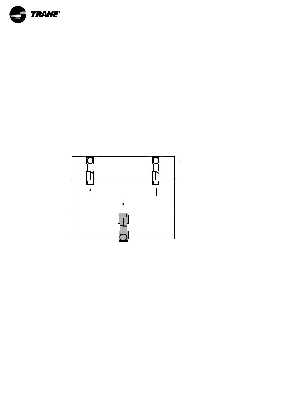
Installation
Clip flush with
outside edge
Snap onto
DIN rail
Insert clips from inside
Read the following guidelines before starting installation.
• Disconnect power prior to installation.
• Reinstall any covers displaced during installation before re-powering unit.
• Mount the meter in an appropriate electrical enclosure near equipment to be monitored.
• Do not install the load side of a variable frequency drive (VFD).
Mount the meter using one of the following two methods:
1. DIN Rail Mount
a. Attach mounting clips to the underside of housing by sliding them into the slots from the
inside.
NNoottee:: The stopping pegs must face the housing and the outside edge of the clip must be
flush with the outside edge of the housing.
b. Snap the clips onto the DIN rail.
BAS-SVX076C-EN
2. Screw Mount
a. Attach mounting clips to the underside of housing by sliding them into the slots from the
inside.
NNoottee:: The stopping pegs must face the housing and the outside edge of the clip must be
flush with the outside edge of the housing.
9

Clip flush with
outside edge
Snap onto
DIN rail
Insert clips from inside
Screw holes
exposed for
mounting
Insert clips from outside
IInnssttaallllaattiioonn
b. Use three (3) #8 screws (not supplied) to mount the meter to the insdie of the enclosure.
10
BAS-SVX076C-EN

Supported Systems
The E50H2-T2 meter has a number of different possible system wiring configurations (Refer to
the table below and next section, Wiring Diagrams). To configure the meter, set the System Type
via the User Interface or by writing the Present_Value of AV2 with the system type value listed in
the following table. The system type tells the meter which of its current and voltage inputs are
valid, which are to be ignored, and if neutral is connected. Setting the correct system type
prevents unwanted energy accumulation on unused inputs, selects the formula to calculate the
Theoretical Maximum System Power, and determines which phase loss algorithm is to be used.
The phase loss algorithm is configured as a percent of the Line-to-Line System Voltage (except
when in System Type 10). In addition, it calculates the expected Line-to-Neutral voltages for
system types that have Neutral (12 & 40). Values that are not valid in a particular System Type
display as ———— on the User Interface or as QQNNAANN in the BACnet objects.
NNoottee:: To avoid distortion, use parallel wires for control power and voltage inputs.
CTs
#
Wires
Single-Phase Wiring
2 1 A 2
2 1 A 2
3 2
Three-Phase Wiring
3 3
4 3
Qty
ID
A,B
A, B, C
A, B, C
Voltage Connections System Type
BACnet
Qty
3
3
4
ID
A, N
A, B
A, B,NL-L w/
A, B, C
A, B,
C, N
Type
L-N 10 1L+1n AN 1
L-L 11 2L AB 2
N 12 2L+1n AB
Delta 31 3L
Grounded
Wye
Object
AV2
40 3L-1n
User
Interface
(SETUP>S
SYS)
Phase Loss Measurement
Bal-
VLL VLN
AN,
AB
AB,
BC,
CA
AB,
BC,
CA
AN,
BN,
CN
ance
ANAB 3
ABBCCA 4
ANBNCN
and
ABBCCA
Wiring
Diagram
Wiring
#
5,6
BAS-SVX076C-EN
11
Wiring
X2
X1
X2
X2
X1
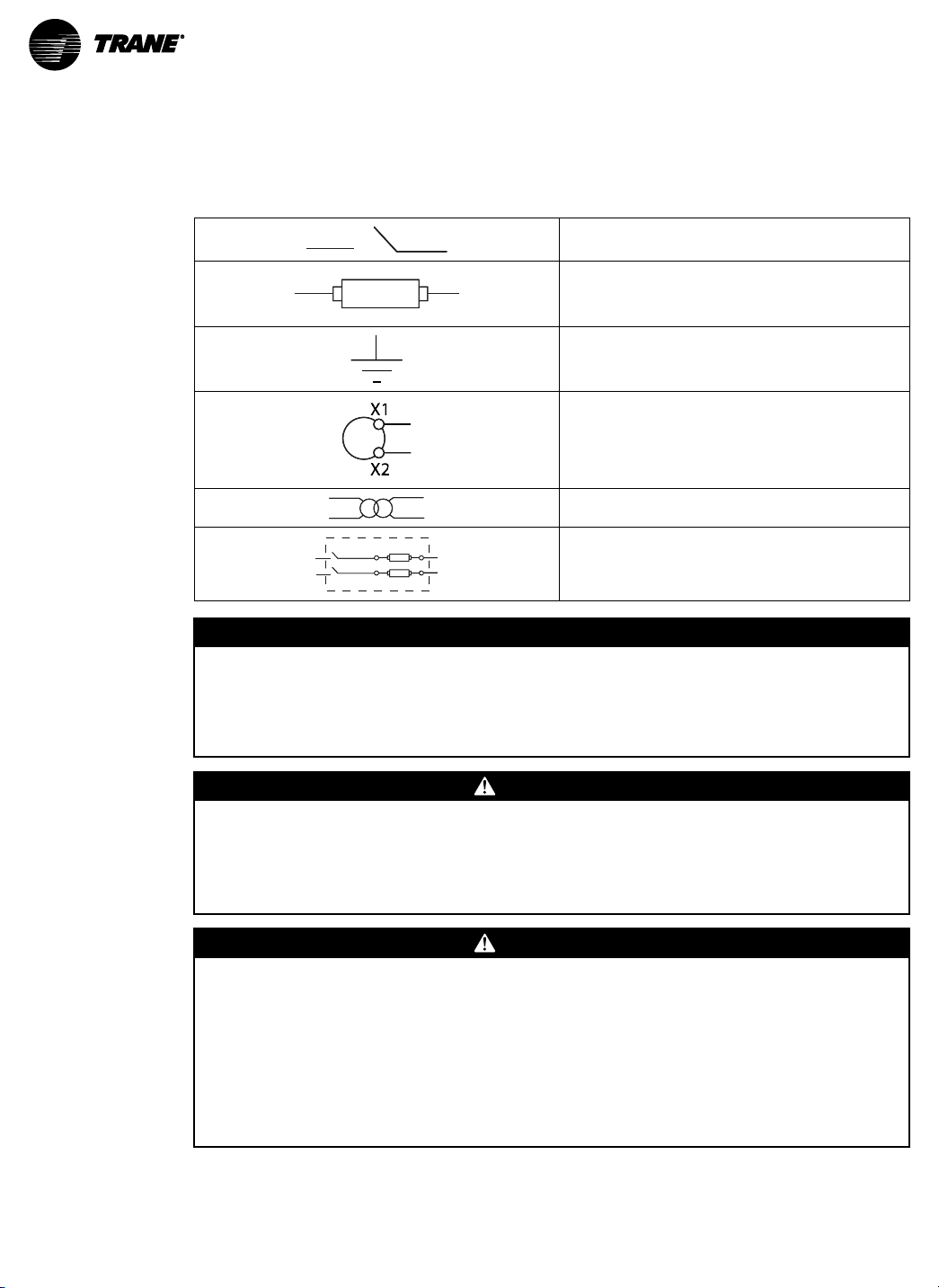
Wiring Symbolism
Refer to the following symbols used in the wiring diagrams.
EEqquuiippmmeenntt DDaammaaggee!!
FFaaiilluurree ttoo ffoollllooww iinnssttrruuccttiioonnss bbeellooww ccoouulldd rreessuulltt iinn oovveerrhheeaattiinngg aanndd ppeerrmmaanneenntt
eeqquuiippmmeenntt ddaammaaggee..
TThhiiss pprroodduucctt iiss ddeessiiggnneedd oonnllyy ffoorr uussee wwiitthh 11 VVoolltt oorr 00..333333 VVoolltt ccuurrrreenntt ttrraannssdduucceerrss.. DDoo nnoott
uussee ccuurrrreenntt oouuttppuutt CCTTss oonn tthhiiss pprroodduucctt..
Voltage Disconnect Switch
Fuse
Note: Installer is responsible for ensuring compliance
with local requirements.
Earth Ground
Current Transducer
Potential Transformer
Protection containing a voltage disconnect switch with
a fuse or disconnect circuit breaker. The protection
device must be rated for the available short circuit
current at the connection point.
NNOOTTIICCEE
12
WWAARRNNIINNGG
HHaazzaarrddoouuss VVoollttaaggee!!
FFaaiilluurree ttoo ddiissccoonnnneecctt ppoowweerr bbeeffoorree sseerrvviicciinngg ccoouulldd rreessuulltt iinn ddeeaatthh oorr sseerriioouuss iinnjjuurryy..
DDiissccoonnnneecctt aallll eelleeccttrriicc ppoowweerr,, iinncclluuddiinngg rreemmoottee ddiissccoonnnneeccttss bbeeffoorree sseerrvviicciinngg.. FFoollllooww
pprrooppeerr lloocckkoouutt//ttaaggoouutt pprroocceedduurreess ttoo eennssuurree tthhee ppoowweerr ccaann nnoott bbee iinnaaddvveerrtteennttllyy
eenneerrggiizzeedd.. VVeerriiffyy tthhaatt nnoo ppoowweerr iiss pprreesseenntt wwiitthh aa vvoollttmmeetteerr..
WWAARRNNIINNGG
HHaazzaarrddoouuss VVoollttaaggee aanndd EEqquuiippmmeenntt DDaammaaggee!!
FFaaiilluurree ttoo ffoollllooww iinnssttrruuccttiioonnss bbeellooww ccoouulldd rreessuulltt iinn ddeeaatthh oorr sseerriioouuss iinnjjuurryy..
CCTT tteerrmmiinnaallss aarree rreeffeerreenncceedd ttoo nneeuuttrraall oonn tthhee mmeetteerr aanndd mmaayy bbee aatt eelleevvaatteedd vvoollttaaggeess.. DDoo
nnoott ccoonnttaacctt mmeetteerr tteerrmmiinnaallss wwhhiillee tthhee uunniitt iiss ccoonnnneecctteedd.. DDoo nnoott ccoonnnneecctt oorr sshhoorrtt ootthheerr
cciirrccuuiittss ttoo tthhee CCTT tteerrmmiinnaallss..
DDiissccoonnnneecctt aallll eelleeccttrriicc ppoowweerr,, iinncclluuddiinngg rreemmoottee ddiissccoonnnneeccttss bbeeffoorree sseerrvviicciinngg.. FFoollllooww
pprrooppeerr lloocckkoouutt//ttaaggoouutt pprroocceedduurreess ttoo eennssuurree tthhee ppoowweerr ccaann nnoott bbee iinnaaddvveerrtteennttllyy
eenneerrggiizzeedd.. VVeerriiffyy tthhaatt nnoo ppoowweerr iiss pprreesseenntt wwiitthh aa CCAATT IIIIII oorr IIVV vvoollttmmeetteerr rraatteedd ppeerr NNFFPPAA
7700EE..
BAS-SVX076C-EN

WWiirriinngg
WWAARRNNIINNGG
EElleeccttrriiccaall SShhoocckk,, EExxpplloossiioonn,, oorr AArrcc FFllaasshh HHaazzaarrdd!!
FFaaiilluurree ttoo ffoollllooww tthheessee iinnssttrruuccttiioonnss ccoouulldd rreessuullttss iinn ddeeaatthh oorr sseerriioouuss iinnjjuurryy..
IInnssttaallll tthhee pprroodduucctt iinn aann aapppprroopprriiaattee eelleeccttrriiccaall//ffiirree eenncclloossuurree ppeerr llooccaall rreegguullaattiioonnss.. DDoo nnoott
iinnssttaallll tthhee pprroodduucctt iinn hhaazzaarrddoouuss oorr ccllaassssiiffiieedd llooccaattiioonnss..
DDoo nnoott uussee tthhee pprroodduucctt ffoorr lliiffee oorr ssaaffeettyy aapppplliiccaattiioonnss..
DDoo nnoott eexxcceeeedd tthhee pprroodduucctt rraattiinnggss oorr mmaaxxiimmuumm lliimmiittss.. PPrroodduuccttss rraatteedd oonnllyy ffoorr bbaassiicc
iinnssuullaattiioonn mmuusstt bbee iinnssttaalllleedd oonn iinnssuullaatteedd ccoonndduuccttoorrss..
CCuurrrreenntt ttrraannssffoorrmmeerr sseeccoonnddaarriieess ((ccuurrrreenntt mmooddee)) mmuusstt bbee sshhoorrtteedd oorr ccoonnnneecctteedd ttoo aa
bbuurrddeenn aatt aallll ttiimmeess..
RReemmoovvee aallll wwiirree ssccrraappss,, ttoooollss,, rreeppllaaccee aallll ddoooorrss,, ccoovveerrss aanndd pprrootteeccttiivvee ddeevviicceess bbeeffoorree
ppoowweerriinngg tthhee eeqquuiippmmeenntt..
BAS-SVX076C-EN
13

N L1
X2
X1
White
Black
A
B
C
N
X1
X2
X1
X2
X1
X2
A
B
C
L1 L2
X2
X1
A
B
C
N
A
B
C
White
Black
X1
X2
X1
X2
X1
X2
L1 L2
X2
X1
X2
X1
A
B
C
N
A
B
C
N
White
Black
White
Black
X1
X2
X1
X2
X1
X2
L1 L2 L3
X2
X1
A
B
C
N
A
B
C
X2
X1
X2
X1
White
Black
White
Black
White
Black
X1
X2
X1
X2
X1
X2
L1N L2 L3
X2
X1
A
B
C
N
A
B
C
X2
X1
X2
X1
White
Black
White
Black
White
Black
X1
X2
X1
X2
X1
X2
White
Black
White
Black
White
Black
L1N L2 L3
X2
X1
A
B
C
N
A
B
C
X2
X1
X2
X1
X1
X2
X1
X2
X1
X2
#1: 1-Phase, Line-to-Neutral, 2-Wire System, 1 CT
Use System Type 10 (1L+1n)
#2: 1-Phase, Line-to-Line, 2-Wire System, 1 CT
Use System Type 11 (2L)
#3: 1-Phase, Direct Voltage Connection, 2 CT
Use System Type 12 (2L+1n)
#5: 3-Phase, 4-Wire, Direct Voltage Input Connection, 3 CT
Use System Type 40 (3L+1n)
#6: 3-Phase, 4-Wire Wye Connection, 3 CT, 3 PT
Use System Type 40 (3L+1n)
#4: 3-Phase, 3-Wire System, 3 CT, No PT
Use System Type 31 (3L)
WWiirriinngg
Wiring Diagrams
Figure 1. 1–Phase and 3–Phase Diagrams
14
BAS-SVX076C-EN

Figure 2. Control Power Diagrams
L1
1 2G
L2 L3
L1N L2 L3
1 2G
1 2G
L1N L2 L3
1 2G
#1: Direct Connect Control Power, Line-to-Line #2: Line-to-Neutral from 90 Vac to
347 Vac (UL) or 300 Vac (CE)
#3: DC Control power from 125 VDC
to 300 VDC (UL and CE max)
Line-to-Line from 90 Vac to 600 Vac (UL). In UL
installations the lines may be floating (such as
a delta). If any lines are tied to an earth (such as
a corner grounded delta), refer to the
Line-to-Neutral installation limits. In CE
compliant installations, the lines must be
neutral (earth) referenced at less than 300 Vac
L-N
#4: Control power transformer may be wired
L-N or L-L. Output to meet meter
input requirements
WWiirriinngg
Fuse Recommendations
Keep the fuses close to the power source. For selecting fuses and circuit breakers, use the
following criteria:.
• Select current interrupt capacity based on the installation category and fault current
capability
• Select over-current protection with a time delay.
• Use a voltage rating sufficient for the input voltage applied.
• Provide over-current protection and disconnecting means to protect the wiring.
• Use the earth connection (G) for electromagnetic compatibility (EMC), not a protective earth
NNoottee:: . For AC installations, use Trane AH04 or equivalent. For DC installations, provide
external circuit protection. Suggested: 0.5A, time delay fuses rated for DC operation at
or above the supply voltage
ground.
BAS-SVX076C-EN
15

Navigating Screens and Setting Parameters
Buttons
(Up)
Select
(Right)
Next
(Down)
Select
(Left)
Back
+
–
These instructions assume the meter is set to factory defaults. If it has been previously
configured, all optional values should be checked.
1. To Navigate to the Setup Screens:
a. Press the + or – button repeatedly until SSEETTUUPP screen displays.
b. Press –>. to advance to the PPAASSWWDD screen.
c. Press –>. through the digits. Press + or – buttons to select the password (the default is
0000000000). Exit the screen to the right.
d. Press –> to advance to the first setup screen (SS BBAACC).
e. Press + or – to select the desired parameter screen to set. After setting parameters, press
+ or – to select the next setup screen or <- to exit and return to SSEETTUUPP.
2. To Enter BACnet Communication Parameters:
a. Press + or – repeatedly until the SETUP screen displays.. . Press -> to accept the value and
advance to the BAUD screen. Press + or – to select the baud rate (default is 19200). Press
-> to advance to the PAR screen. Press + or – to select the parity (default is NONE). Press
-> to return to the S COM screen.
b. Press -> to advance to the S COM (Set Communications) setup screen.
c. Press -> to advance to the MAC screen and through the address digits. Press + or – to
select the BACnet MAC address (default is 000011).
d. Press -> to accept the value and advance to the KBAUD scrfeen. Press + or – to select the
baud rate (default is 7766..88 kk).
e. Press -> to advance to the ID1 screen and through the upper four digits of the Device
Instance. Press + or – to select the ID digits. The setup screen splits the Device ID into two
parts— the most significant four digits (ID1) and the least significant three digits (ID2). The
E50HxA supports BACnet Device ID values from 1 to 4,193,999. Units are shipped with a
factory default setting that is pseudo-randomly generated in the range from 1,000,000 to
3,097,151.
f. Press -> to accept the value and advance to the ID2 screen and through the lower three
digits of the Device Instance. Press + or – to select the ID digits.
g. Press -> to accept the value and to return to the S BAC screen.
3. To Enter the CT Output Voltage and Input Current Ranges:
a. Press –> to advance to the CCTT SSZZ screen and through the digits. Press + or – buttons to
select the CT size in amps (default is 110000).
b. Press –> to return to the SS CCTT screen.
16
4. To Enter the Service Type to Monitor:
a. Press –> to advance to the SS SSYYSS (Set System) screen.
b. Press –> to advance to the SSYYSSTTMM screen. Press + or – buttons to select the configuration
(default is 33LLNN--11NN).
c. Press –> to return to the SS SSYYSS screen.
BAS-SVX076C-EN

Pulse Contact Input
SComm
Output
+
~10 kΩ
Comm
Ground
4-10 VDC
nominal
Equivalent
Circuit
Pulse Input Contacts
The E50H2-T2 has one input with pulse accumulator as described above, and one phase loss
alarm output terminal.
Figure 3. Pulse Contact Input
BAS-SVX076C-EN
17

User Interface
The user can set the display mode to either IEC or IEEE notation in the SETUP menu.
Table 1. User Interface Menu Abbreviations
Main Menu Main Menu
IEC IEEE Description IEC IEEE Description
D D Demand F ERR F ERR Frequency Error
MAX M Maximum
P W Present Real
Q VAR Present
S VA Present
A A Amps ALERT ALERT Diagnostic Alert
UAB, UBC,
UAC
V VLN Voltage Line
PF PF Power Factor OS OS Operating System
U VLL Voltage Line-
HZ HZ Frequency SN SN Serial Number
KSh KVAh Accumulated
KQh KVARh Accumulated
KPh KWh Accumulated
PLOSS PLOSS Phase Loss DEMND DEMND Reset Demand
LOWPF LOWPF Low Power
VAB, VBC,
VAC
Demand
Power
Reactive
Power
Apparent
Power
Voltage Lineto-Line
to Neutral
to-Line
Apparent
Reactive
Real Energy
Factor Error
I OVR I OVR Over Current
V OVR V OVR Over Voltage
PULSE PULSE kWh Pulse Output
_PHASE _PHASE Summary Data for
INFO INFO
MODEL MODEL Model Number
RS RS Reset System
RESET RESET Reset Data
PASWD PASWD Enter Reset or
ENERG ENERG Reset Energy
Overrun
(configuration
error)
1, 2, or 3 active
phases
Status
Unit Information
Setup Password
Accumulators
Maximums
18
BAS-SVX076C-EN

Figure 4. Data Configuration
UUsseerr IInntteerrffaaccee
BAS-SVX076C-EN
19
UUsseerr IInntteerrffaaccee
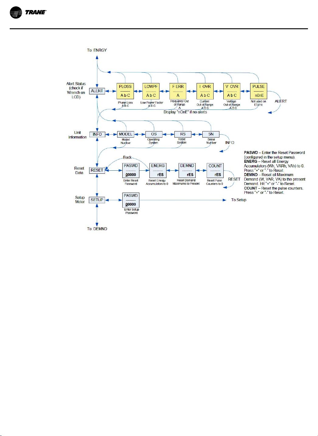
Figure 5. Alert and Reset Information
20
BAS-SVX076C-EN

Figure 6. User Interface for Setup
UUsseerr IInntteerrffaaccee
BAS-SVX076C-EN
21

UUsseerr IInntteerrffaaccee
Figure 7. User Interface for Setup (continued)
22
BAS-SVX076C-EN

RS-485 Communications
–
+
S
Shielded Wire
120 Ω terminators on the first/last devices of daisy chain
Notes:
• The voltage and current ratings on the terminals are compliant with the requirements
of the EIA RS-485 communications standard.
• The RS-485 transceivers are ¼ unit load or less.
• RS-485+ has a 47 kΩ pull up to +5V, and RS-485- has a 47 kΩ pull down to
Shield (RS-485 signal ground).
• Wire the RS-485 Bus as a daisy chain from device-to-device, without any stubs.
Use 120 Ω termination resistors at each end of the bus (not included).
• Shield is not internally connected to Earth Ground.
• Connect Shield to Earth Ground somewhere on the RS-485 bus (only at one point).
For all terminals on E50 meters:
• When tightening terminals, apply the correct torque: 0.37-0.44 ft·lb (0.5-0.6 N·m).
• Use 14-24 gauge (2.1-0.2 mm
2
) wire.
The RS-485 secondary port allows the power meter to be connected in a daisy chain with up to
63, 2–wire devices.
BAS-SVX076C-EN
23

Standard BACnet Default Settings
Setting
Setup Password 00000 —
Reset Password 00000 —
System Type 40 (3+N) Wye AV2
CT Primary Ratio 100 amp AV3
PT Ratio 1:1 (none) AV5
System Voltage 600 V L-L AV6
Maximum Theoretical Power Calculated from AV2, AV3, AV4,
Display Mode 1 (IEEE) AV7
Phase Loss Voltage Threshold
Demand: Number of sub-intervals
length
Demand: Sub-interval Length 900 sec (15 min)- AV11 default
BACnet MAC Address 001 —
BACnet TP Baud Rate 76.8 kBaud —
BACnet TP Max_Requestor 127 Device
BACnet Device_ID
BACnet Device Location Installed location not yet identified Device
(a)
Default values are preset at the factory. Once changed, defaults can no longer be automatically reset- they must be restored
individually. The baud rate and MAC address are set through the user-interface screens, and all other values are set by rewriting each Object.
Default Values
AV5, and AV6 (with default settings,
power is 103.92 kW
• 10% of system voltage
• 25% phase-to-phase imbalance
1 (block mode) AV10
value is 90000 [1/100 seconds]
Pseudo-random value from
1,000,000 to 3,097,151
(a)
BACnet Object
AI45
• AV8
• AV9
AV11
Device
24
BAS-SVX076C-EN

BACnet Programming
BACnet Programming Overview
The E50H2-T2 is programmable via BACnet protocol and can easily be connected to a BACnet TP
network using an off-the shelf BACnet router. It uses five types of BACnet objects. A standard
PICS (below) describes the required characteristics of the BACnet implementation, but this
additional descriptive context may be helpful to the integrator.
In addition to the required properties, the device object utilizes some optional properties to
support other functionality, Time Synchronization (primarily used for data/trend logging on the
device) and Description and Location properties to simplify installation and maintenance.
Configure all of the meter’s functions, other than data logging and writable Device Properties, by
writing the Present_Value of the 11 Analog_Value objects. These values (except for the
configuration register, AV1, which always returns zero when read) are all readable and stored in
nonvolatile memory so that they are retained if power to the device is interrupted.
Data values are accessed by reading the Present_Value of the 52 Analog_Input objects. Most of
these values are instantaneous readings of measured service parameters. Some of them, (AI1,
AI26, AI27, AI37-AI45, AI47, AI50 and AI51) represent accumulated values and are stored in
nonvolatile memory as well. If power to the device is interrupted, these values are retained, but
no additional information accumulates until the device completes its re-initialization.
Alerts are used to indicate conditions of potential concern to the installer or the system, such as
input voltage or current on any phase that exceeds the meter’s measurement range, phase
voltage below the Phase Loss Threshold set by the user, or Power Factor below 0.5 on any phase.
Alerts are accessible individually by reading the Present_Value of the Binary_Input objects or as a
group by reading the Present_Value of Analog_Input object 52. Alerts are not latched and do not
generate events to system. They indicate presence of these conditions at the time they are read,
but the device does not latch and store them until they are read (if the condition changes before
they are read, the alert will go away).
All Analog_Value, Analog_Input, and Binary_Input objects implement the reliability property and
use it to indicate that the Present_Value properties are functional, valid and current. For complete
assurance, check the Reliabilty property for a No_Fault_ Detected status before reading the
Present_Value of any AV, AI or BI objects.
• BACnet Protocol Implementation Conformance Statement (PICS)
– Date: January 1, 2013
– Vendor Name: Veris Industries, LLC
– Product Name: E50Hx Energy Meter
– Product Model Number: E50Hx
– Applications Software Version: 1
– Firmware Revision: x.xxx
– BACnet Protocol Revision: 4
– Product Description: 3-phase electrical energy meter
• BACnet Standardized Device Profile (Annex L)
– BACnet Application Specific Controller (B-ASC)
• List all BACnet Interoperability Building Blocks Supported (Annex K)
– DS-RP-B, DS-RPM-B, DS-WP-B, DM-DDB-B, DM-DOB-B, DM-DCC-B, DM-TS-B, DM-RD-B
• Segmentation Capability
– Segmentation not supported
• Standard Object Types Supported
NNoottee:: No dynamic Creation or Deletion supported; no proprietary properties or object types.
– Device Object
BAS-SVX076C-EN
25

BBAACCnneett PPrrooggrraammmmiinngg
– Analog_Input Objects
– Analog_Value Objects
• Data Link Layer Options
– EIA-485 Token Passing, Requestor (Clause 9), Baud Rate(s): 9600, 19200, 38400, 76800,
• Device Address Binding
– Static device binding is not supported. No client functionality is included.
• Networking Options
– None
• Character Sets Supported
– ANSI X3.4
• Optional Properties Supported: Max_Requestor, Max_Info_Frames, Description,
Location, Local_Time, Local_Date Writable Properties: Object_Identifier, Object_Name,
Max_Requestor, Location Property Range Restrictions: Object_Identifier – May only
write values from 1 to 4,193,999; Location – (limited to 64 characters); Max_Requestor
– May only write values from 1 to 127
• Optional Properties Supported: Description, Reliability No Writable Properties
• Optional Properties Supported: Description, Reliability
• Writable Properties: Only the Present_Value is writable
• Property Range Restrictions
• AV1: May only write 30078, 21211, 21212 and 16498
• AV2: May only write 10, 11, 12, 31 and 40
• AV3: May only write values from 5 to 5000
• AV4: May only write value 32768
• AV5: May only write values from 0.01 to 320.0
• AV6: May only write values such that AV6/AV5 is from 82 to 660 (absolute range is
82-32000). To ensure AV6 accepts/rejects the proper values, set AV5 first.
• AV7: May only write values 0 and 1
• AV8: May only write values from 1 to 99
• AV9: May only write values from 1 to 99
• AV10: May only write values from 1 to 6
• AV11: May only write the value 0 or a value from 1000 to 3276700 in multiples of
100
• Binary_Input Objects
• Optional Properties Supported: Description, Reliability
• No writable properties
115200.
BACnet Programming Objects
The following tables provide information about BACnet object types and descriptions.
Legend:
• R = Read, R/W= Read or Write
• NV= Value is stored in non-volatile memory. The value(s) is still available in the event of
power loss or reset.
• Units= Lists the physical units that a register holds.
26
BAS-SVX076C-EN

Device Object
BBAACCnneett PPrrooggrraammmmiinngg
Figure 8. Device Object
Figure 9. Device Object (continued)
Analog Value (AV) Objects
Use the Present_Value property of the Analog_Value object for all writable variables in the meter
other than those used specifically for BACnet configuration, Time Synchronization (in the Device
Object).
Values are checked when written, and errors are returned for invalid entries. This table describes
how the meter uses those variables, what values are valid, and what their defaults are. When
writing values to the Present_Value properties of Analog_Value BACnet objects, there is a delay
of up to about two seconds to validate and store the new value. An immediate read of the same
property before that delay has elapsed can return the prior value (even if the new value was
accepted). To read a value immediately after writing it, check the Reliability property first. When
it reports a No_Fault_Detected status, the Present_Value of the object is current. These objects
BAS-SVX076C-EN
27

BBAACCnneett PPrrooggrraammmmiinngg
support the Description and Reliability object properties and all required Analog_Value object
properties, but Present_Value is the only writable property.
Figure 10. Analog Values (AV)
Figure 11. Analog Values (AV) [continued]
Analog Input (AI) Objects
Use the Present_Value property of the Analog_Input objects for all read-only numeric variables in
the meter other than those used specifically for device configuration (in the Device Object). .
These objects support the Description and Reliability object properties and all required Analog_
Input object properties. None of them are writable. The values that are not instantaneous (i.e.,
Accumulated Energy, Max Demand, Pulse Input Counts) are non-volatile. They are not updated
while control power is inactive, but their past values are retained when power is restored. The
Present_Value of the accumulated data objects (AI1, AI26-AI27 and AI42-AI44) use floating-point
28
BAS-SVX076C-EN
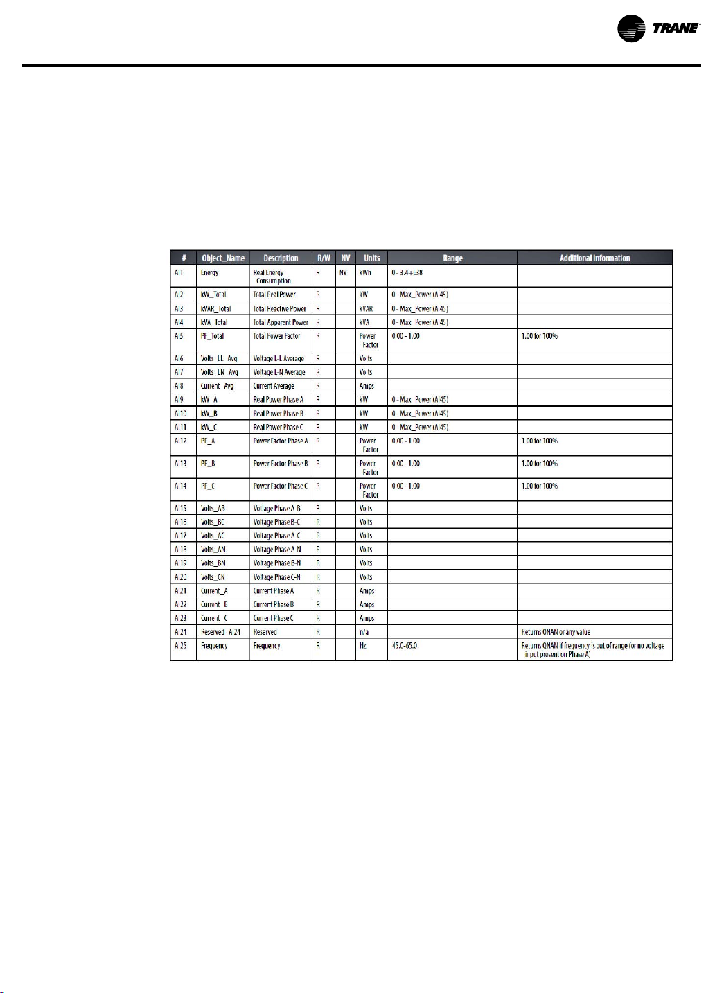
BBAACCnneett PPrrooggrraammmmiinngg
data types (all AI objects use floating point data points). The resolution of the accumulated values
decreases as the value grows larger over time and more of the significant digits precede the
decimal point. If the size of the value limits the resolution unacceptably, read and store the
current value offline and reset the accumulators to restore finer resolution.
NNoottee:: As a best practice, verify the Reliabilty property for a No_Fault_Detected status before
reading the Present_Value. If the line voltage or input frequency of the system being
monitored falls out of the supported range, the corresponding alert bits (BI1-BI7) are set
and the reliability property of any values that cannot be accurately measured under those
conditions returns Unreliable_Other.
Figure 12. Analog Inputs (AI)
BAS-SVX076C-EN
29

BBAACCnneett PPrrooggrraammmmiinngg
Figure 13. Analog Inputs (AI) [continued]
30
BAS-SVX076C-EN
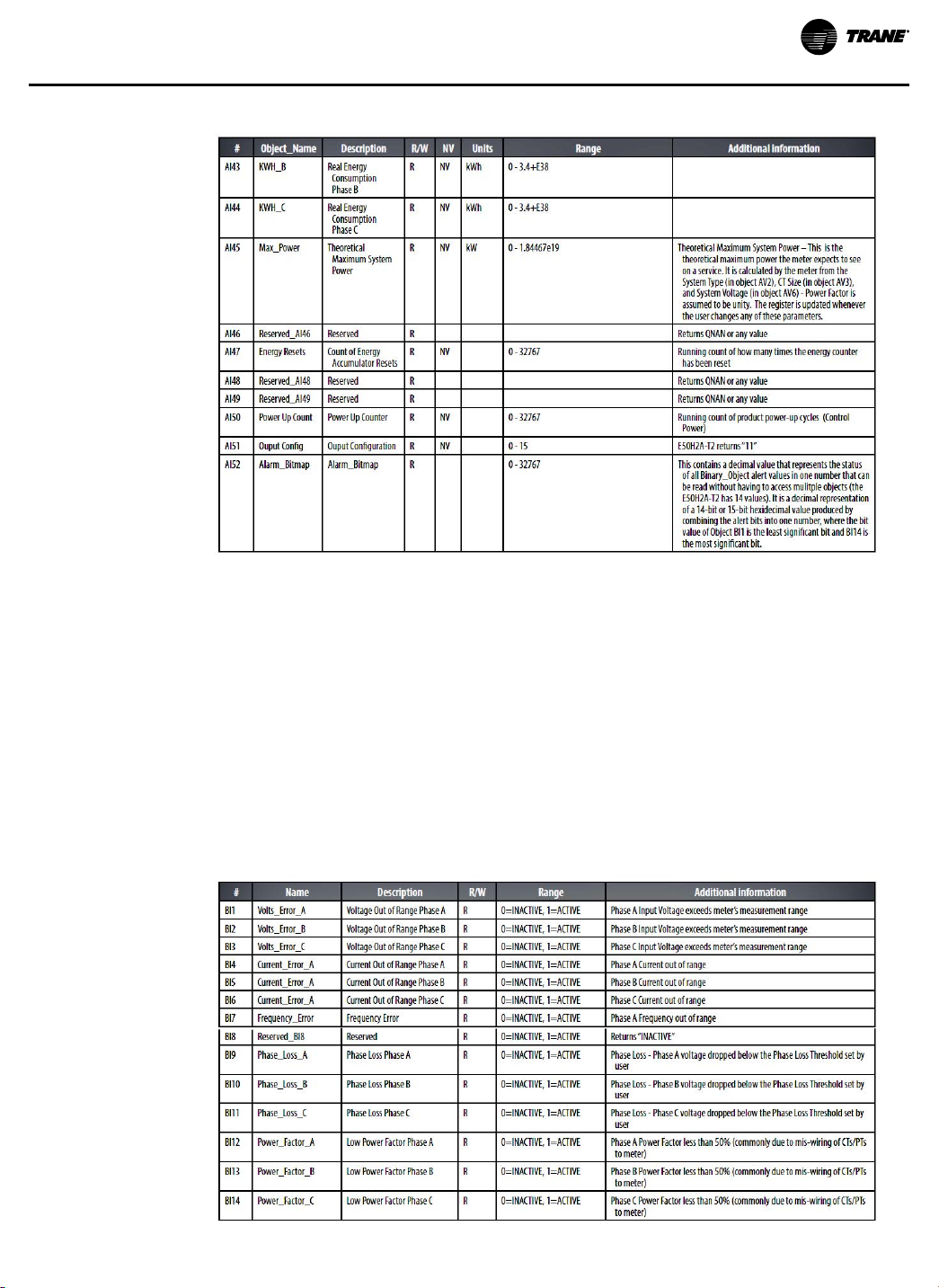
Figure 14. Analog Inputs (AI) [continued]
BBAACCnneett PPrrooggrraammmmiinngg
Binary Input (BI) Objects
Use the Present_Value properties of the Binary_Input objects as alerts for conditions of potential
concern regarding to the system measurement. These values are dynamic and are not latched,
so if the condition is resolved, the alert goes inactive, whether it has been read or not.
These objects support the Description and Reliability object properties and all required Binary_
Input object properties. None of them are writable. For complete assurance, check the Reliabilty
property for a No_Fault_Detected status before reading the Present_Value.
To test the meter’s alert status, read the Present_Value of each of the Binary_Input objects
representing the alert bits of interest, or read the Present_Value of AI52, which combines all these
bits into a single decimal value. AI52 represents the status of all 14 Binary_Object alert values in
one number that can be read without having to access mulitple objects. The bit value of Object
BI1 is the least significant bit and BI14 is the most significant bit.
Figure 15. Binary Inputs (BI)
BAS-SVX076C-EN
31

Troubleshooting
Problem Cause Solution
The
maintenance
wrench icon
appears in the
power meter
display.
There is a problem with the inputs
to the power meter.
Refer to the Alert sub-menu or Diagnostic Alert Modbus
Register 146.
The display is
blank after
applying.
The data
displayed is
inaccurate.
Cannot
communicate
with power
meter from a
remote
personal
computer.
The meter is not receiving adequate
power.
Incorrect setup values.
Incorrect voltage inputs.
Power meter is wired improperly.
Power meter address is incorrect.
Power meter baud rate is incorrect.
Communications lines are
improperly connected.
• Verify that the meter control power are receiving the
required voltage.
• Verify that the heart icon is blinking.Check the fuse.
Verify the values entered for power meter setup
parameters (CT and PT ratings, system type, etc.).
Check power meter voltage input terminals to verify
adequate voltage.
Check all CTs and PTs to verify correct connection to the
same service, PT polarity, and adequate powering.
Verify that the meter is correctly addressed.
Verify that the baud rate of the meter matches that of all
other devices on its communications link.
• Verify the terminating resistors are properly installed
on both ends of a chain of units. Units in the middle of
a chain should not have a terminator.
• Verify the power meter communications connections.
• Verify the shield ground is connected between all
units.
32
BAS-SVX076C-EN

China RoHS Compliance
Hazardous Substances
Part Name Pb
(a)
Electronic
(a)
X indicates that concentration of hazardous substance in at least one of the homogeneous materials used for this part is
above the limit as stipulated in GB/T 26572.
(b)
O indicates that the concentration of hazardous substance in all of the homogeneous materials for this part is below the limit
as stipulated in GB/T 26572.
X
Hg
O
Cd
(b)
O O O O
Cr, VI
PBB PBDE
BAS-SVX076C-EN
33

Additional Resources
• E50 Series Compact Power and Energy Meter, BBAACCnneett ((EE5500HH22--TT22)) and Modbus (E50C2-T2),
Installation Instructions (X39641310001)
• Product Data Sheet Enhanced Power and Energy Meters E50 Series Models, Product Data
Sheet (BAS-PRD035)
• Quick Installation Guide (Z207411-0A 0217)
34
BAS-SVX076C-EN

NNootteess
BAS-SVX076C-EN
35

Trane - by Trane Technologies (NYSE: TT), a global innovator - creates comfortable, energy efficient
indoor environments for commercial and residential applications. For more information, please visit
trane.com or tranetechnologies.com.
Trane has a policy of continuous product and product data improvements and reserves the right to change design and specifications without
notice. We are committed to using environmentally conscious print practices.
BAS-SVX076C-EN 22 Apr 2021
Supersedes BAS-SVX076B-EN (April 2020)
©2021 Trane
 Loading...