

Trane Duplex Water-Cooled Hermetic CenTraVac Installation Manual
Installation
Duplex Water-Cooled
™
Hermetic CenTraVac
CH530 Controller
With
Cooling Only
Direct Drive with CH530 Control Panel
X39640669020
CDHF-SVN01B-EN

Warnings and
Cautions
Warnings and Cautions
Notice that warnings and cautions
appear at appropriate intervals
throughout this manual. Warnings
are provided to alert installing
contractors to potential hazards that
could result in personal injury or
death, while cautions are designed
to alert personnel to conditions that
could result in equipment damage.
Your personal safety and the proper
operation of this machine depend
upon the strict observance of these
precautions.
NOTICE:
Warnings and Cautions appear at appropriate sections throughout this manual.
Read these carefully.
WARNING – Indicates a potentially hazardous situation which, if not avoided, could result in
death or serious injury.
CAUTION – Indicates a potentially hazardous situation which, if not avoided, may result in
minor or moderate injury. It may also be used to alert against unsafe practices.
CAUTION – Indicates a situation that may result in equipment or property-damage-only accidents.
© 2005 American Standard Inc. All rights reserved. CDHF-SVN01B-EN

Contents
Warnings and Cautions
General Information
Water Piping
Vent Line Piping
Insulation
Electrical Information
Trane Supplied Starter
Customer Supplied Starter
Line Power Supply
PFCC
PFCC and Unit Mounted Starters
Remote Starter
2
4
25
35
41
43
44
45
47
48
50
51
CDHF-SVN01B-EN
Starter to UCP Control Wiring
Control Circuit Wiring
System Control Wiring
Wiring Diagrams
53
54
56
59
3

General Information
About this Manual
Original date of manual:
This manual contains information
regarding installation of Models
CDHF 60 Hz and CDHG 50 Hz chillers
equipped with Tracer CH530
controller. Reference is made to the
CDHF. All installation procedures
described for the CDHF apply also to
the CDHG. By carefully reviewing the
information in this manual and
following the instructions given
along with the submittal package
provided for the unit will assure that
the chiller is installed correctly.
Product Description Block
Trane 60 Hz. Model CDHF hermetic
CenTraVac
product definition and selection
system (PDS). Each unit is defined by
the product description block which
appears on the unit nameplate. An
explanation of the PDS product code
is provided in the unit operation and
maintenance literature.
™
units are defined by the
4
CDHF-SVN01B-EN

General Information
Commonly Used Acronyms
ASME = American Society of
Mechanical Engineers
ASHRAE = American Society of
Heating, Refrigerant and Air
Conditioning Engineers
BAS = Building Automation System
LBU = La Crosse Business Unit
CABS = Auxiliary Condenser TubeBundle Size
CDBS = Condenser Bundle Size
CDSZ = Condenser Shell Size
CWR = Chilled Water Reset
DTFL = Delta-T at Full Load (i.e., the
difference between entering and
leaving chilled water temperatures at
design load)
EVBS = Evaporator Bundle Size
EVSZ = Evaporator Shell Size
GPM = Gallons-per-Minute
HVAC = Heating, Ventilating, and Air
Conditioning
IE = Internally Enhanced Tubes
IPC = Interprocessor Communication
PFCC = Power Factor Correction
Capacitor
PSID = Pounds-per-Square-Inch
(differential pressure)
PSIG = Pounds-per-Square-Inch
(gauge pressure)
UCP = Chiller Control Panel
CH530 = Tracer CH530 Chiller
Controller
Warnings and Cautions
Notice that WARNINGS and
CAUTIONS appear at appropriate
intervals throughout this manual.
WARNINGS are provided to alert
installing contractors to potential
hazards that could result in personal
injury or death, while CAUTIONS are
designed to alert personnel to
conditions that could result in
equipment damage.
Your personal safety and the proper
installation of this machine depend
upon the strict observance of these
precautions.
Unit Nameplate
The CDHF unit nameplate is located
on the left side of the left hand unit
control panel (UCP). A typical unit
nameplate is illustrated in Figure 1.
The following information is
provided on the CDHF unit
nameplate.
- Unit model and size descriptor
- Unit serial number
- Unit electrical requirements
- Correct operating charge and type
of refrigerant.
- Unit test pressures and maximum
operating pressures
- Unit Installation and Operation and
Maintenance manuals
- Product description block (identifies
all unit components and unit
“design sequence” used to order
literature and make other inquiries
about the unit).
CDHF-SVN01B-EN
Metric Conversion
The following conversions apply for
tables and charts in this manual,
In. x 2.54 = cm
Ft. x 30.48 = cm.
Lb. x .453 = kg.
5

General Information
Figure 1 – Information from a Typical CDHF Unit Nameplate
MODEL: CDHF2000 DATE OF MFG (DD/MM/YY): @TODAY05
MODEL NO:
CDHF2000KR0TA2802745B0A106B0A1CFFRR10W4C0010330001S
SERIAL NO: S.O. NO: SAMPLE
RATED VOLTAGE: 4160 VOLTS 60 HZ 3 PH
VOLTAGE UTILIZATION RANGE: 3744-4576 VAC
LH CIRCUIT RH CIRCUIT
MINIMUM CIRCUIT AMPACITY: 96 AMPS 103 AMPS
MAXIMUM OVERCURRENT
PROTECTIVE DEVICE: 150 AMPS 175 AMPS
COMPRESSOR MOTOR MAX
VOLTS-AC HZ PH RLA KW LRAY
LH CIRCUIT 4160 60 3 75 480 400
RH CIRCUIT 4160 60 3 82 523 473
VOLT HZ PH
OIL TANK HEATER (LH&RH): 115 60 1 750 WATTS
CONTROL CIRCUIT (LH&RH): 115 60 1 4000 VA MAX
CARBON TANK HEATER (LH&RH):115 60 1 1.7 RLA
PUMPOUT COMPRESSOR(LH&RH): 115 60/50 1 1.55 RLA
PURGE COMP MTR(LH&RH): 115/110 60/50 1 8RLA 34.6LRA
WHEN MOTOR CONTROLLER PROVIDED BY OTHERS
TRANE ENGINEERING SPEC. S6516-0513 APPLIES
REFRIGERANT SYSTEM LH RH
FIELD CHARGED WITH: 1850 1850 LBS. OF R-123
ACTUALLY CHARGED WITH: LBS. OF R-123
MAXIMUM WORKING PRESSURE: 15 15 PSIG HIGH SIDE
MAXIMUM WORKING PRESSURE: 15 15 PSIG LOW SIDE
FACTORY TEST PRESSURE:
HIGH SIDE 45 PSIG LOW SIDE 45 PSIG
FIELD LEAK TEST PRESSURE 8 PSIG MAX.
TESTED AT PSIG
MANUFACTURED UNDER ONE OR MORE OF THE FOLLOWING
U.S. PATENTS: 4232533 4686834 4689967 4715190
4751653 4800732 5031410 5056032 5058031 5355691
5434738 5537830 5553997 5563489 5600960 5675978
5836382 5848538 6065297 6098422 6250101
SERVICE LITERATURE
INSTALLATION MANUAL: CDHF-SVN01A-EN
OPERATION/MAINTENANCE MANUAL: CDHF-SVU01A-EN
PRODUCT DESCRIPTION:
TVSQ 1 PTON 1975 VTR1 165 VTR2 165
CTM1 75 CTM2 100 MAC1 6 MAC2 6
MODL CDHF DSEQ R0 NTON 2000 VOLT 4160
HRTZ 60 CPM1 512 CPD1 280 CPM2 588
CPD2 274 EVSZ 210D EVBS 1850 EVTM TECU
EVTH 35 EFLD WATE EVWT MAR EVWP 1
EVWC STD EVPR 150 EVCO VICT EVWA RRLR
CDSZ 210D CDBS 1900 CDTM TECU CDTH 35
CFLD WATE CDWT MAR CDWP 1 CDWC STD
CDPR 150 CDCO VICT CDWA LFRF ORC1 1265
ORC2 1265 AGLT UL TEST CWSP TTOL SPCL
WCNM BNMP CNIF CH53 OPST YES WPSR WFC
TRMM TRM4 EPRO YES CDRP YES SPKG DOM
ASCL OUTS APTY STD SRT1 CXL SRT2 CXL
SOPT 3RTD GENR NO
6
CDHF-SVN01B-EN

General Information
Responsibilities of Installing
Contractors
For your convenience, a summary of
the contractor responsibilities
typically associated with the chiller
installation process is provided
below. Table 1 further categorizes
these responsibilities by
differentiating between Tranesupplied and field-supplied and field
installed components.
Refer to the Installation section of
this manual for more detailed
instructions.
• Locate and maintain the loose
parts, i.e. isolators, bulb wells,
temperature sensors, flow sensors
or other factory-ordered field
installed options, for installation as
required. Loose parts are located in
the starter panel on units with
factory-installed unit-mounted
starters or in the motor terminal
box for units with remote-mounted
starters.
• Install unit on a foundation with flat
support surfaces level within 1/16”,
and of sufficient strength to
support concentrated loading.
Place manufacturer-supplied
isolation pad assemblies under
unit. (Use spring isolators for upper
floor installations).
• Install unit per applicable Trane
installation manual.
• Complete all water piping and
electrical connections.
Note: Field-piping must be arranged
and supported to avoid stress on the
equipment. It is strongly
recommended that the piping
contractor refrain from piping closer
than 3’-0” minimum to the
equipment. This will allow for proper
fit-up upon arrival of the unit at the
jobsite. Any adjustment that is
necessary can be made to the piping
at that time.
• Where specified, supply and install
valves in water piping upstream
and downstream of evaporator and
condenser water boxes to isolate
shells for maintenance, and to
balance/trim system.
• Supply and install flow switches (or
equivalent devices) in both chilled
water and condenser water piping.
Interlock each switch with proper
pump starter to ensure unit can
only operate when water flow is
established.
• Supply and install taps for
thermometers and pressure
gauges in water piping adjacent to
inlet and outlet connections of both
evaporator and condenser.
• Supply and install drain valves on
each water box.
• Supply and install vent cocks on
each water box.
• Where specified, supply and install
strainers ahead of all pumps and
automatic modulating valves.
• Supply and install pressure relief
piping from pressure-relief rupture
disc to atmosphere.
• If necessary, supply sufficient
Refrigerant-HCFC-22 (maximum of
1 lb. per machine) and dry nitrogen
(8 psig per machine) for pressure
testing under manufacturer’s
supervision.
• Start unit under supervision of a
qualified service technician.
• Where specified, supply and
insulate evaporator and any other
portions of machine as required to
prevent sweating under normal
operating conditions.
• Unit-Mounted Starters Only,
remove top of starter panel and cut
access area for line-side wiring;
front left quadrant of top provides
recommended access to starter
lugs.
• Supply and install wire terminal
lugs to starter.
• Unit-Mounted Starters Only,
Supply and install field wiring to
line-side lugs of starter.
• Supply and install a Refrigerant
Monitor per ASHRAE 15
specifications. Reference the
compliance to ASHRAE Standard
15 as shown on the “Model
CenTraVac
Request for Serviceman”.
To obtain a copy of “Model
CenTraVac
for Serviceman” (Form 1-27.08-6)
order from your local Trane office.
™
Checksheet and
™
Checksheet and Request
CDHF-SVN01B-EN
7
General Information
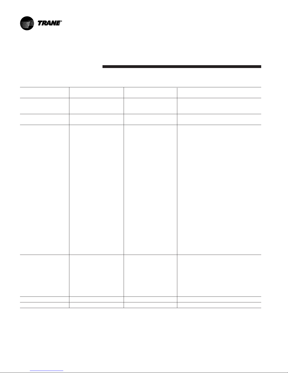
Table 1 – Installation Requirements
Type of Trane-Supplied Trane-Supplied Field-Supplied
Requirement Trane-Installed Field-Installed Field-Installed
Rigging A. Safety chains
B. Clevis connectors
C. Lifting beam
Isolation A. Isolation pads or A. Isolation pads or spring isolators
spring isolators
Electrical A. Circuit breakers or A. Jumper bars A. Circuit breakers or fusible
fusible disconnects B. Temperature sensor disconnects (optional)
(optional) (optional outdoor air) B. Remote-mounted starter
B. Unit-mounted C. Flow switches (may C. PFCCs (Remote-mounted
starter (optional) be field supplied) starter option only)
C. PFCCs (optional) D. Terminal lugs
E. Ground connection(s)
F. Jumper bars
G. BAS wiring (optional)
H. IPC wiring (remote-
mounted starters only
I. Control voltage wiring
(remote-mounted starters only)
J. Oil pump interlock wiring
(remote-mounted
starters only)
K. High condenser pressure
interlock wiring
(remote-mounted starters only).
L. Chilled water pump contactor
and wiring
M.Condenser water pump
contactor and wiring
N. Option relays and wiring
(See Table 14 & 16)
Water Piping A. Flow switches (May A. Thermometers
be field supplied) B. Water flow pressure gauges
C. Isolation and balancing valves
water piping
D. Vents and drain valves
(1 each per class)
E. Pressure-relief valves
(for water boxes as required)
Rupture Disc A. Rupture disc assy A. Vent line and flexible connector
Insulation A. Insulation (Optional) A. Insulation
8
CDHF-SVN01B-EN

General Information
Unit Shipment
Each chiller ships from the factory as
a hermetically assembled package; it
is factory piped, wired and tested. All
openings are covered or plugged to
prevent contamination during
shipment and handling.
See Figure 2 for an illustration of a
typical unit and its components. As
soon as the unit arrives at the job
site, inspect it thoroughly for
damage and material shortages. In
addition:
1. Verify the chiller’s hermetic
integrity by checking the
evaporator pressure for an
indication of holding charge
pressure.
Note: Since there are two refrigerant
circuits both must be checked.
To prevent damaging moisture from
entering the unit and causing
corrosion, each chiller is pressurized
with dry nitrogen before shipment.
Note: The holding charge should
register approximately 5 psig (at sea
level) on the gauge. If the charge has
escaped, contact your local Trane
sales office for instructions.
2. Check the oil sump sight glasses
to verify that the sump was
factory-charged with 9 gallons of
oil. If no oil level is visible, contact
your local Trane sales office.
3. Compare the unit nameplate data
(including electrical characteristics)
with the corresponding ordering
and shipping information to verify
that the correct unit was shipped
to the job site.
If a thorough inspection of the
chiller reveals damage or material
shortages, be sure to file these
claims with the carrier
immediately. Specify the extent
and type of damage found, and
notify the appropriate Trane sales
representative. Do not install a
damaged unit without the sales
representative’s approval!
Storage
If the chiller will be stored at the job
site for an extended period of time
before it is installed, exercise these
precautionary measures to protect
the unit from damage:
1. Do not remove the protective
coverings factory-installed on the
control panel and compressor
inlet vane actuator for shipment.
2. Store the chiller in a dry vibration
free and secure area. If factory
insulated, protect chiller from
prolonged exposure to sunlight.
CAUTION
Insulation Damage!
To prevent damage to the factoryinstalled insulation, do not allow
excessive exposure to sunlight.
3. Periodically check the condenser
and evaporator pressure to verify
that the 5 psig dry nitrogen at 72°F
ambient holding charge is still in
the chiller. If this charge escapes,
contact a qualified service
organization and the Trane sales
engineer that handled the order.
Note: The storage range for the
microcomputer-based devices in the
unit control panel is -40°F to 158°F
(-40°C to 70°C).
CDHF-SVN01B-EN
9
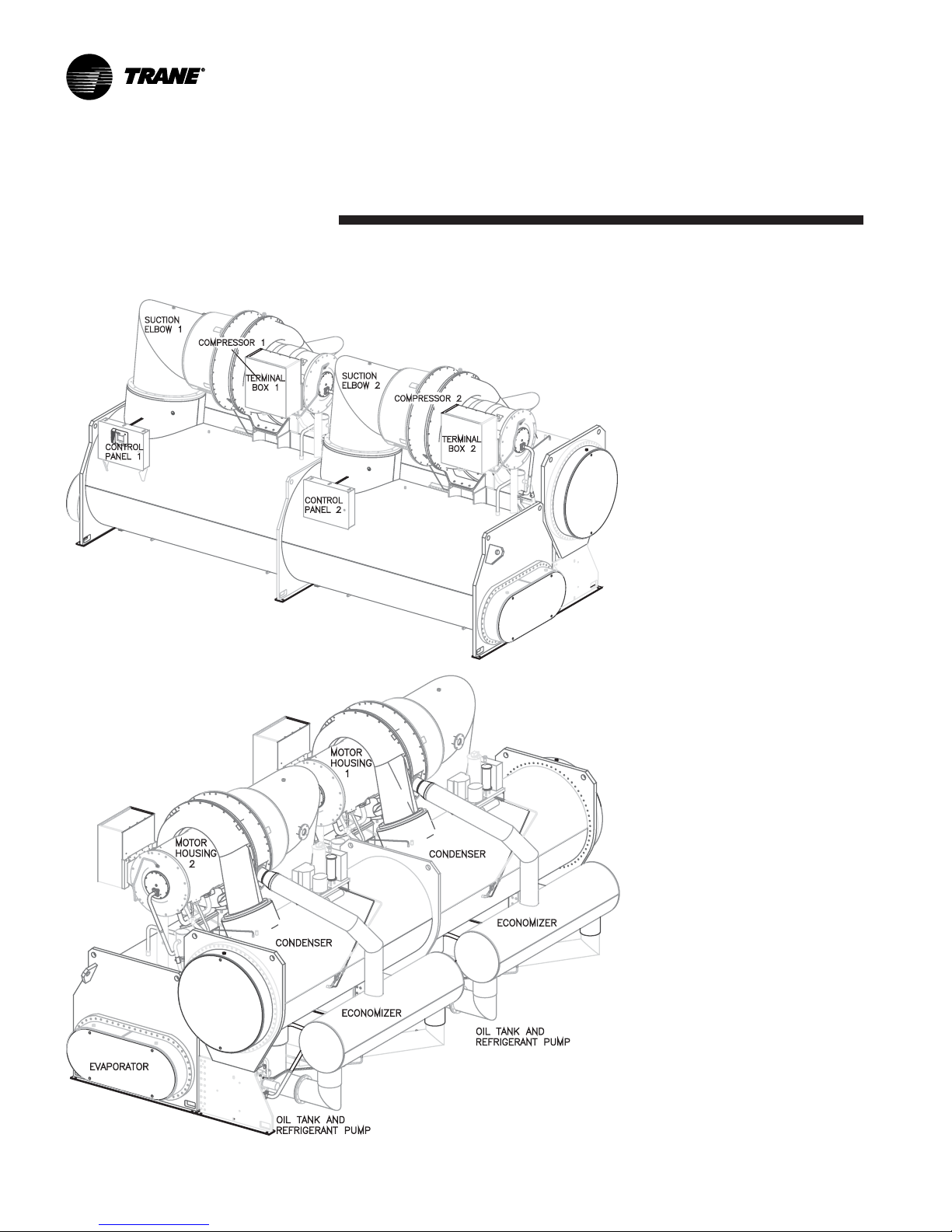
Figure 2 – Typical CDHF Chiller
General Information
10
CDHF-SVN01B-EN

General Information
Recommended Unit
Clearances
Adequate clearance around and
above the chiller is required to allow
sufficient access for service and
maintenance operations.
Figure 3 illustrates the
recommended clearances for units
with and without options. Figure 4
shows tube bundle locations. Notice
that, in each instance, the minimum
vertical clearance above the chiller is
3-feet.
In addition, be sure to provide at
least 3-feet of working space in front
of the unit control panel to satisfy the
National Electrical Code, and/or local
codes.
Important! Do not install piping or
conduit above the compressor
motor assembly or behind the
suction elbow!
Note: Specific unit clearance
requirements are also indicated in
the submittal package provided for
your unit.
Operating Environment
Besides assuring that the site
selected for chiller installation
provides the necessary clearances,
consider the equipment’s operating
environment.
To assure that electrical components
operate properly, do not locate the
chiller in an area exposed to dust,
dirt, corrosive fumes, or excessive
heat and humidity. Note that the
maximum ambient temperature for
chiller operation is 95 to 100°F (35° 38° C).
CAUTION
Equipment Failure!
CDHF operation at ambient
temperatures exceeding 100°F
(38°C) can fatigue the unit’s rupture
disc, causing it to break at a reduced
refrigerant pressure (i.e., <15 psig).
Starter component damage can also
occur because of the panel’s inability
to dissipate heat adequately.
If any of these adverse operating
conditions are present, take
whatever action is necessary to
improve the equipment room
environment.
Foundation Requirements
Provide rigid, non-warping
mounting pads or a concrete
foundation as a mounting surface for
the chiller. Ensure that the base is of
sufficient strength and mass to
properly support the chiller at its full
operating weight (i.e., including
completed piping, and full operating
charges of refrigerant, oil and water).
For your convenience, a summary of
standard unit shipping and operating
weights is provided in Table 2.
Notice that the floor loading for all
sizes of chillers is 60 pounds per
square inch.
To assure proper unit operation, the
chiller must be level within 1/16”
over its length and width when set
into place on the mounting surface.
Trane will not assume responsibility
for equipment problems resulting
from an improperly designed or
constructed foundation.
CDHF-SVN01B-EN
11
General Information
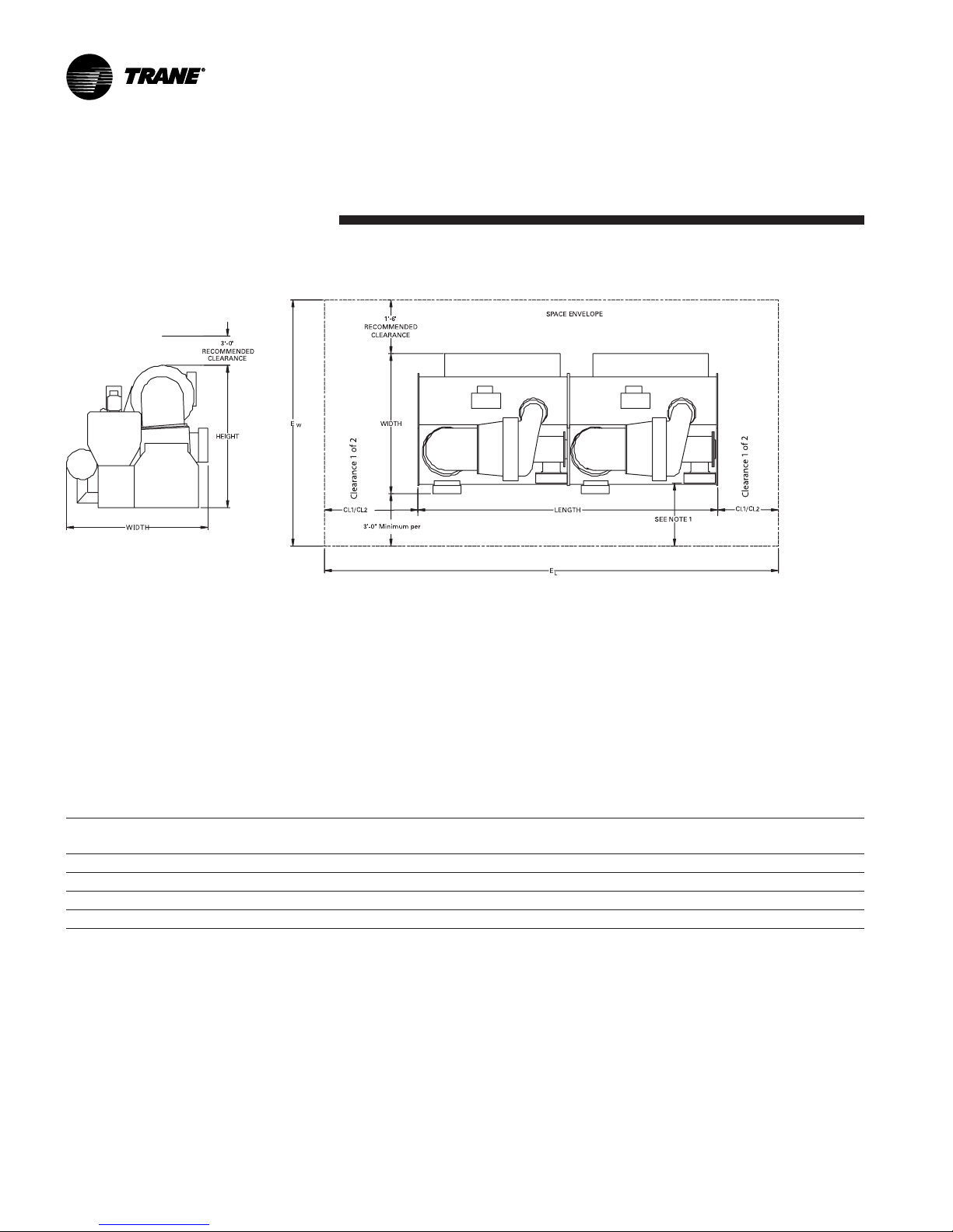
Figure 3 – Clearance Requirements for Standard CDHF
Notes:
1. Per NEC Article 110 - Unit mounted starters from 0-600V require 42" clearance; 601-2500V require 48" clearance;
2501-9000V require 60" clearance.
2. Clearance 1 can be at either end of machine and is required for tube pull clearance
Clearance 2 is always at the opposite end of machine from Clearance1 and is required for service clearance
3. Clearance requirement for evaporator tube removal does not include water box. Add water box dimension to this
figure.
UCP Clearance Requirements for Standard CDHF
CL1 CL2
Shell Width Entire Width Height Length Entire Length Clearance 1 Clearance 2
210 D 130.875 184.875 132.750 258.000 606.000 264.000 84.000
250 D 142.625 196.625 136.875 258.000 606.000 264.000 84.000
250 M 142.625 196.625 141.375 312.000 714.000 318.000 84.000
250 X 142.625 196.625 141.375 360.000 810.000 366.000 84.000
12
CDHF-SVN01B-EN
General Information
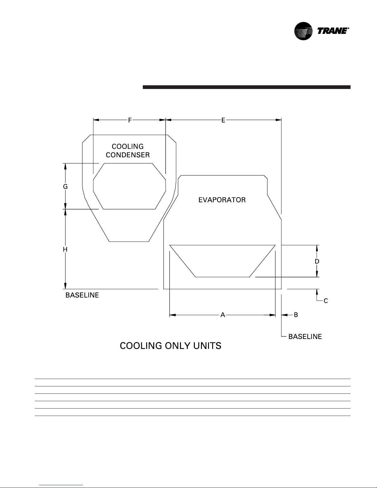
Figure 4 – Tube Bundle Locations for Model CDHF Units
Cooling Only and Free Cooling Units
EVSZ CDSZ A B C D E F G H
210 D 210 D 4’-5-7/16" 5"-3/8" 7’-9/16" 1’-4-1/4" 5’-0-1/8" 3’-5-1/4" 2’-5" 3’-10-3/16"
250 D 250 D 5’-0-3/4" 5"-1/4 6"-1/2 1’-7-1/4" 5’-8-3/4" 3’-10-5/8" 2’-4-1/8" 3’-11-5/8"
250 M 250 M 5’-0-3/4" 5"-1/4 6"-1/2 1’-7-1/4" 5’-8-3/4" 3’-10-5/8" 2’-4-1/8" 3’-11-5/8"
250 X 250 X 5’-0-3/4" 5"-1/4 6"-1/2 1’-7-1/4" 5’-8-3/4" 3’-10-5/8" 2’-4-1/8" 3’-11-5/8"
CDHF-SVN01B-EN
13
General Information
Table 2 – Typical Shipping and Operating Weights
Operating Weight Shipping Weight
TYPE NTON CPKW EVSZ CDSZ (lbs) (kg) (lbs) (kg)
CDHF 1500-2000 957 210D 210D 80171 36366 68629 31130
CDHF 2100-2500 1228 250D 250D 93186 42269 79213 35931
CDHG 1250-1750 716 210D 210D 82349 37354 70807 32118
CDHG 2150 892 210D 210D 89680 197710 78288 172595
CDHG 2150 892 250D 250D 96964 43983 82991 37645
CDHF 3000 1340 250M 250M 106659 48381 89425 40563
CDHF 3500 1340 250X 250X 114445 51912 95077 43127
Notes:
Weights shown above are accurate within +/- 3% and are based on the following
Operating weights include refrigerant, oil charge and water
Shells are with largest bundles and TECU .028 wall tubes
Compressor weight with medium voltage motor and above CPKW
Starter weights not included
Waterboxes are 1 pass, 150 psig Non-Marine
For other configurations refer to submittal package
14
CDHF-SVN01B-EN

General Information
Note: Immediately report any unit
damage incurred during handling or
installation at the job site to the
Trane sales office.
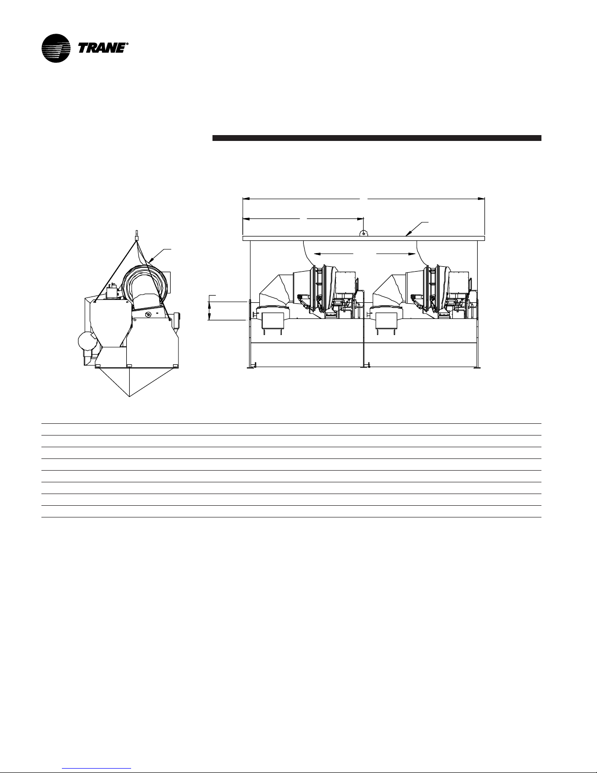
Rigging
Lifting is the recommended method
for moving chillers. Suggested lifting
arrangements for standard units are
illustrated in Figure 5.
Note that each of the cables used to
lift the unit must be capable of
supporting the entire weight of the
chiller. (See Table 2 for unit shipping
and operating weights.) Notice that
the lifting beam used to lift the unit
must be at least 23 feet long.
See Figure 5 and Table 2 for
guidance in selecting cable or sling
lengths.
WARNING
Test Lift!
Verify chiller remains horizontal.
To avoid serious injury and possible
equipment damage, lift the chiller
horizontally; use the lifting
arrangement and rigging shown in
Figure 5. Failure to lift unit as
recommended could result in death
or serious injury or lead to
equipment damage.
To lift the chiller properly, insert
clevis connections at the points
indicated in Figure 5; a 2-1/2”
diameter lifting hole is provided at
each of these points. Next, attach the
lifting cables or slings.
Once the lifting cables are in place,
attach a safety cable or sling
between the first-stage casting of the
compressor and the lifting beam. To
do this, remove a retaining bolt from
the compressor first-stage casting
and replace it with an eyebolt, or
swivel clevis.
Note: There should not be tension
on this safety cable; it is used only to
prevent the unit from rolling during
the lift.
When the lift is completed, detach
the clevis connections and safety
chain, then remove the eyebolt that
was used to secure the safety chain
to the compressor, and reinstall the
retaining bolt in its place. If the chiller
cannot be moved using the
conventional rigging method just
described, consider these points.
1. If job site conditions require
rigging of the chiller at an angle
greater than 45° from horizontal
(end-to-end), dowel-pin the compressor and remove it from the
unit. Be sure to contact a qualified
service organization for specific
rigging instructions.
2. When lifting the chiller is either
impractical or undesirable, attach
cables or chains to the jacking
slots shown in Figure 5; then push
or pull the unit across a smooth
surface. Should the chiller be on a
shipping skid, it is not necessary to
remove the shipping skid from the
chiller before moving it into place.
CAUTION
Equipment Damage!
To prevent possible equipment
damage, do not use a fork lift to
move the chiller!
CAUTION
Compressor Alignment!
Lifting the compressor/motor
assembly from the shells without
factory-installed doweling in the
compressor casting flanges may
result in misalignment of the
compressor castings.
3. Position isolator pads (or spring
isolators) beneath the chiller feet;
see “Unit Isolation” section for
instructions.
4. Once the isolators are in place,
lower the chiller; again, work from
end to end in small increments to
maintain stability.
CDHF-SVN01B-EN
CAUTION
Oil Loss!
To prevent oil migration out of the
oil tank during lifting procedures,
remove the oil from the oil tank if
the unit will be lifted at any angle
greater than 15° from horizontal
end-to-end. If oil is allowed to run
out of the oil tank into other areas of
the chiller, it will be extremely
difficult to return the oil to the oil
tank even during operation.
15
General Information
Figure 5 – Recommended Lifting Arrangements for CDHF
Y
B
Jacking
A
Points
Safety
C
Chain
X
Safety
Chain
H
LIFTING
BEAM
TYPE NTON EVSZ CDSZ X Y H
CDHF 1500-2000 210D 210D 143 in. 23 ft 24.75 in
CDHF 2100-2500 250D 250D 143 in. 23 ft 24.75 in
CDHG 1250-1750 210D 210D 143 in. 23 ft 24.75 in
CDHG 2150 210D 210D 143 in. 23 ft 24.75 in
CDHG 2150 250D 250D 143 in. 23 ft 24.75 in
CDHF 3000 250M 250M 172 in. 27.5 ft 24.75 in
CDHF 3500 250X 250X 199 in. 31.5 ft 24.75 in
Notes:
1. Lifting chains (or cables) are not the same length between point A and B, or between points A and C. Adjust as
necessary for an even lift.
2. Lifting holes provided on chillers to attach chains are 2 1/2 inch in diameter.
3. Attach safety chain (or cable) as shown, and without tension. The safety chain is not used for lifting, but is there to
prevent the unit from rolling.
4. Do not fork-lift the unit.
16
CDHF-SVN01B-EN
General Information
Unit Isolation
To minimize sound and vibration
transmission through the building
structure - and to assure proper
weight distribution over the
mounting surface, always install
isolation pads or spring isolators
under the chiller feet.
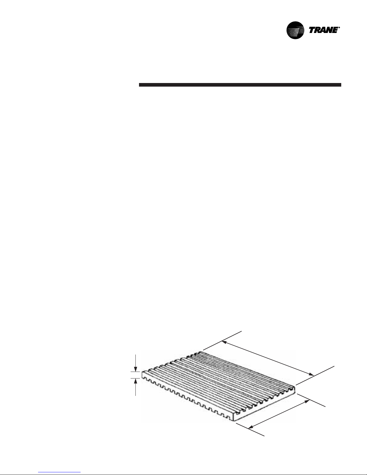
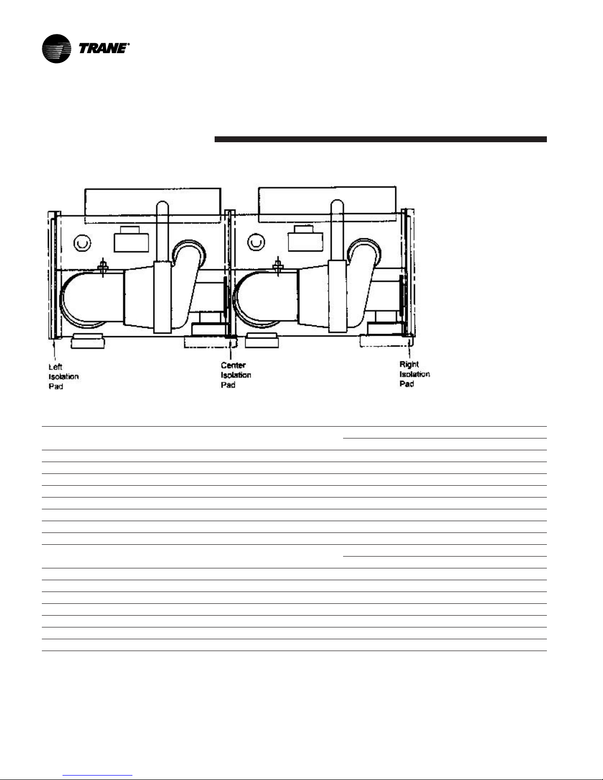
Note: Isolation pads (Figure 6) are
provided with each chiller unless
spring isolators are specified on the
sales order.
Note: The center support is
approximately 1/2" shorter (higher)
than the end supports. After unit
leveling, shim the center isolator
pads. If spring isolators are used,
shim the isolators for the center
support. See Figure 7.
Specific isolator loading data is
provided in the unit submittal
package. If necessary, contact your
local Trane sales office for further
information.
Important! When determining
placement of isolation pads or spring
isolators, remember that the control
panel side of the unit is always
designated as the unit front.
Isolation Pads
When the unit is ready for final
placement, position isolation pads
under the chiller feet as shown in
Figure 7.
Remember that the chiller must be
level within 1/16” over its length and
width after it is lowered onto the
isolation pads. In addition, all piping
connected to the chiller must be
properly isolated and supported so
that it does not place any stress on
the unit.
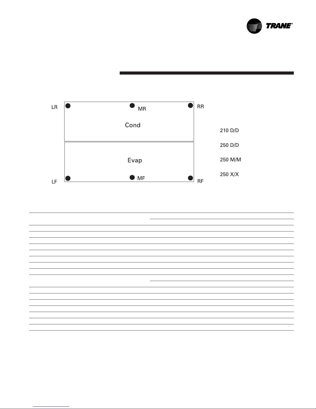
Spring Isolators
Spring isolators should be
considered whenever chiller
installation is planned for an upper
story location. Base isolator selection
and placement on the information
presented in Figures 8-10a. (Notice
that 3 types of spring isolators - each
with its own maximum loading
characteristics are used with CDHF
chillers).
Spring isolators typically ship
assembled and ready for installation.
To install and adjust the isolators
properly, follow the instructions
given.
Note: Do not adjust the isolators
until the chiller is piped and charged
with refrigerant and water.
1. Position the spring isolators under
the chiller as shown in Figures 8
and 9. Make sure that each isolator
is centered in relation to the tube
sheet.
Note: Spring isolators shipped with
the chiller are not identical! Be sure
to compare the data provided in the
unit submittal package and Figures 8
through 10a to determine proper
isolator placement.
2. Set the isolators on the sub-base;
shim as necessary to provide a
flat, level surface at the same
elevation for the end supports,
and approximately 1/2" higher for
the center support. Be sure to
support the full underside of the
isolator base plate; do not straddle
gaps or small shims.
[8-10 mm]
CDHF-SVN01B-EN
Figure 6 – Isolation Pad
18"
[457 mm]
5/16-3/8"
6"
[152.4 mm]
17
General Information
Figure 7 – Isolation Pad Placement - CDHF, CDHG
Important:
Center support is 1/2" (13mm) shorter than end supports. Requires 1/2" steel shim under pad for Center
Support at installation after leveling.
Isolation Pad Loading (lb)
TYPE NTON CPKW EVSZ CDSZ Left Pad Center Pad Right Pad
CDHF 1500-2000 957 210D 210D 25150 26718 28304
CDHF 2100-2500 1228 250D 250D 29292 31056 32838
CDHG 1250-1750 716 210D 210D 25997 27446 28907
CDHG 2150 892 210D 210D 26507 29850 33322
CDHG 2150 892 250D 250D 20680 32316 33967
CDHF 3000 1340 250M 250M 33527 35546 37586
CDHF 3500 1340 250X 250X 35975 38140 40330
TYPE NTON CPKW EVSZ CDSZ Left Pad Center Pad Right Pad
CDHF 1500-2000 957 210D 210D 11408 12119 12839
CDHF 2100-2500 1228 250D 250D 13287 14087 14895
CDHG 1250-1750 716 210D 210D 11792 12449 13112
CDHG 2150 892 210D 210D 58438 65808 73462
CDHG 2150 892 250D 250D 13916 14659 15407
CDHF 3000 1340 250M 250M 15208 16123 17049
CDHF 3500 1340 250X 250X 16318 17300 18294
Notes:
Isolator pad loading is based on the following
Operating weights include refrigerant, oil charge and water
Shells are with largest bundles and TECU .028 wall tubes
Compressor weight with medium voltage motor and above CPKW
Starter weights not included
Waterboxes are 1 pass, 150 psig Non-Marine
For other configurations refer to submittal package
18
Isolation Pad Loading (kg)
CDHF-SVN01B-EN
General Information
Figure 8 – Spring Isolator Placement - CDHF, CDHG
Estimated Spring Isolator Loading (lb)
TYPE NTON CPKW EVSZ CDSZ LF MF RF LR MR RR
CDHF 1500-2000 957 210D 210D 14120 14948 15785 11029 11770 12519
CDHF 2100-2500 1228 250D 250D 13861 14721 15591 15431 16334 17247
CDHG 1250-1750 716 210D 210D 14432 15193 15960 11564 12253 12947
CDHG 2150 892 210D 210D 15623 17428 19299 10884 12422 14023
CDHG 2150 892 250D 250D 14413 15209 16012 16267 17108 17955
CDHF 3000 1340 250M 250M 15865 16850 17845 17663 18696 19741
CDHF 3500 1340 250X 250X 17023 18080 19148 18952 20060 21182
Estimated Spring Isolator Loading (kg)
TYPE NTON CPKW EVSZ CDSZ LF MF RF LR MR RR
CDHF 1500-2000 957 210D 210D 6405 6780 7160 5003 5339 5679
CDHF 2100-2500 1228 250D 250D 6287 6678 7072 7000 7409 7823
CDHG 1250-1750 716 210D 210D 6546 6892 7239 5246 5558 5873
CDHG 2150 892 210D 210D 34443 38422 42547 23995 27386 30915
CDHG 2150 892 250D 250D 6538 6899 7263 7379 7760 8145
CDHF 3000 1340 250M 250M 7196 7643 8095 8012 8480 8954
CDHF 3500 1340 250X 250X 7722 8201 8686 8597 9099 9608
Notes:
Vibration isolator loading is based on the following
Operating weights include refrigerant, oil charge and water
Shells are with largest bundles and TECU .028 wall tubes
Compressor weight with medium voltage motor and above CPKW
Starter weights not included
Waterboxes are 1 pass, 150 psig Non-Marine
For other configurations refer to submittal package
CDHF-SVN01B-EN
19
General Information
Figure 9 – Chiller Foot/Isolator Orientation
Side View of Unit
Center tube sheet
support leg
Center of
Isolator Spring
Note: The spring isolator must be centered in relation
to the tube sheet. Do not align the isolator with the
flat part of the chiller foot, because the tube sheet is
often off-center.
3. If required, bolt the isolators to the
floor through the slots provided,
or cement the pads.
Note: Fastening the isolators to the
floor is not necessary unless
specified.
4. If the chiller must be fastened to
the isolators, insert capscrews
through the chiller base and into
the holes tapped in the upper
housing of each isolator. However,
do not allow the screws to
protrude below the underside of
the isolator upper housing. An
alternative method of fastening
the chiller to the isolators is to
cement the neoprene pads.
5. Set the chiller on the isolators;
refer to “Rigging” for lifting
instructions.
The weight of the chiller will force
the upper housing of each isolator
down, perhaps causing it to rest
on the isolator’s lower housing.
(Figure 10, 10a illustrates spring
isolator construction.)
6. Check the clearance (labeled X in
Figure 10, 10a ) on each isolator. If
this dimension is less than 1/4” on
any isolator, use a wrench to turn
the adjusting bolt one complete
revolution upward.
Note: When the load is applied to
the isolators (Step 5), the top plate
of each isolator moves down to
compress the springs until either:
a. The springs support the load; or
b. The top plate rests on the
bottom housing of the isolator.
1. If the springs are supporting
End View of Unit
Outside edge of
tube sheet
Note: Place isolator near outside
edge of tube sheet as shown.
the load, screwing down on
the adjusting bolt (Step 7) will
immediately begin to raise
the chiller.
End of tube
sheet
7. Turn the adjusting bolt on each of
the remaining isolators to obtain
the required minimum clearance
at X (Figure 10, 10a ) of 1/4”.
8. Once the minimum required
clearance is obtained on each of
the isolators, level the chiller by
turning the adjusting bolt on each
of the isolators on the low side of
the unit. Be sure to work from one
isolator to the next. Remember
that the chiller must be level to
within 1/16”: over its length and
width, and that clearance X of
each isolator must be at least 1/4
inch.
20
CDHF-SVN01B-EN
General Information
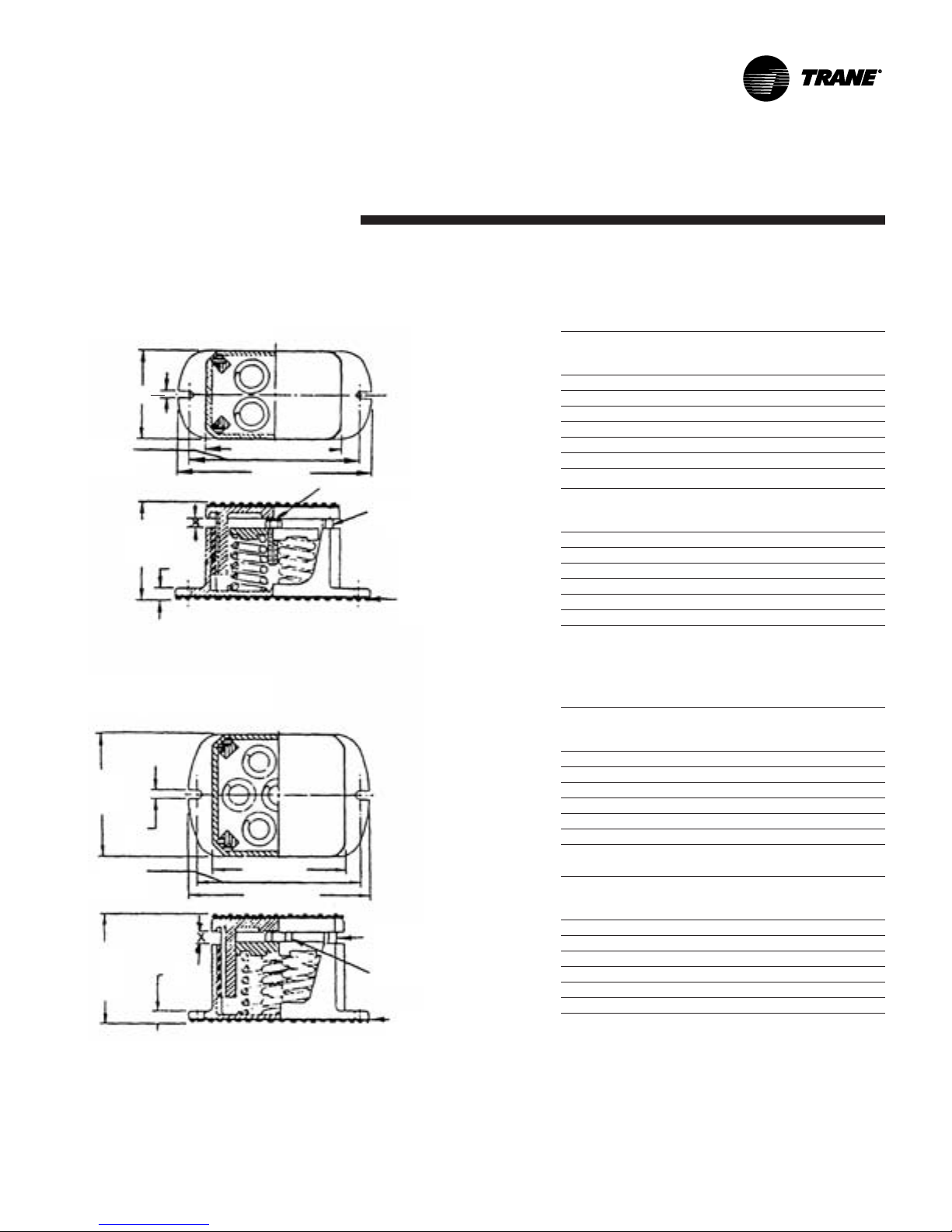
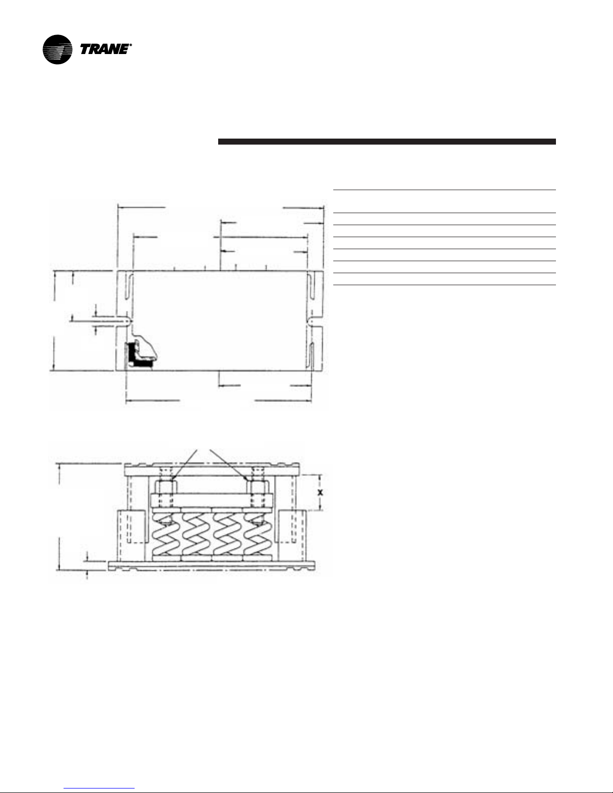
Figure 10 – Typical Spring Isolator Types and Construction
Type CT-4 Spring Isolators
5/8" [16 mm]
9-1/4"
[235 mm]
C-C
foundation
bolts
6-1/2" [165 mm]
Free Height
7-1/2" [191 mm]
10-1/4"
[260 mm]
Adjusting Bolt
Adjust the isolator so
that the upper
housing clears the
lower housing by at
least 1/4” [6 mm]
Acoustical nonskid
neoprene pad (top
and bottom)
Isolator Maximum Spring
Type Load Deflection Color
and Size (lbs.) (Inches) Coding
CT-4-25 1,800 1.22 Red
CT-4-26 2,400 1.17 Purple
CT-4-27 3,000 1.06 Orange
CT-4-28 3,600 1.02 Green
CT-4-31 4,400 0.83 Gray
CT-4-32 5,200 0.74 White
Isolator Maximum Spring
Type Load Deflection Color
and Size (Kg) (mm) Coding
CT-4-25 816 31 Red
CT-4-26 1,089 30 Purple
CT-4-27 1,361 27 Orange
CT-4-28 1,633 26 Green
CT-4-31 1,996 21 Gray
CT-4-32 2,359 19 White
Type CT-7 Spring Isolators
5/8"
[16 mm]
8-3/4" [222
mm] C-C
foundation
bolts
6-5/8" [168
mm] Free
Height
5/8"
[16 mm]
7-1/4"
[184 mm]
9-3/4"
[248 mm]
Adjust the isolator so that
the upper housing clears the
lower housing by at least
1/4” [6 mm]
Adjusting Bolt
Acoustical nonskid
neoprene pad (top
and bottom)
Isolator Maximum Spring
Type Load Deflection Color
and Size (lbs.) (Inches) Coding
CT-7-25 3,150 1.22 Red
CT-7-26 4,200 1.17 Purple
CT-7-27 5,250 1.06 Orange
CT-7-28 6,300 1.02 Green
CT-7-31 7,700 0.83 Gray
CT-7-32 9,100 0.74 White
Isolator Maximum Spring
Type Load Deflection Color
and Size (Kg) (mm) Coding
CT-7-25 1,429 31 Red
CT-7-26 1,905 30 Purple
CT7-27 2,381 27 Orange
CT-7-28 2,858 26 Green
CT-7-31 3,493 21 Gray
CT-7-32 4,128 19 White
CDHF-SVN01B-EN
21
General Information
Figure 10A – Typical Spring Isolator Types and Construction
CT-12 Spring Isolators
14-3/4" [375 mm]
7-3/8" [187 mm]
6-1/2"
[165 mm]
6-5/8"
[168 mm]
7"
[178
mm]
3-1/2"
[89 mm]
5/8"
[16 mm]
12-1/2"
[318 mm]
13-1/4" [337 mm]
Isolator Max Deflection Spring
Type/Size Load lb (kg) inches (mm) Color Code
CT-12-25 5,400 1.22 Red
CT-12-26 7,200 1.17 Purple
CT-12-27 9,000 1.06 Orange
CT-12-28 10,800 1.02 Green
CT-12-31 13,200 0.83 Gray
CT-12-32 15,600 0.74 White
8-1/8" [206
mm] Free
Height
5/8"
[16 mm]
(2) Adjusting Bolts
Adjust the isolator so that
the upper housing clears the
lower housing by at least
1/4” [6.4 mm]
Acoustical nonskid
neoprene pad (top
and bottom)
22
CDHF-SVN01B-EN

CT-16 and CT20
Spring Isolators
General Information
Isolator Max Deflection Spring
Type/Size Load lb (kg) inches (mm) Color Code
CT 16-26 9600 (4355) 1.17 (29.7) Purple
CT 16-27 12000 (5443) 1.06 (26.9) Orange
CT 16-28 14400 (6532) 1.02 (25.9) Green
CT 16-31 17600 (7983) 0.83 (21.1) Gray
CT 16-32 20800 (9435) 0.74 (18.8) White
Isolator Max Deflection Spring
Type/Size Load lb (kg) inches (mm) Color Code
CT 20-26 12000 (5443) 1.17 (29.7) Purple
CT 20-27 15000 (6804) 1.06 (26.9) Orange
CT 20-28 18000 (8165) 1.02 (25.9) Green
CT 20-31 22000 (9979) 0.83 (21.1) Gray
CT 20-32 26000 (11794) 0.74 (18.8) White
CDHF-SVN01B-EN
23
General Information
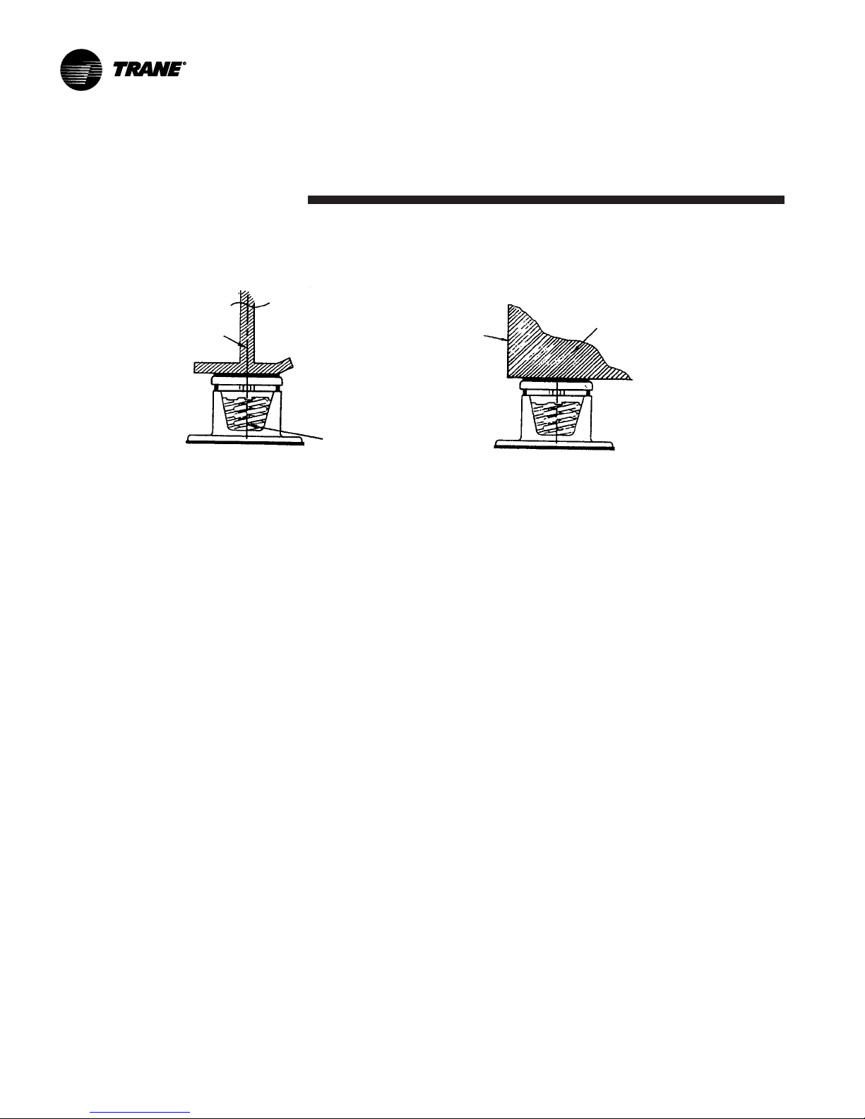
Unit Leveling
Follow the instructions outlined
below and illustrated in Figure 11 to
determined whether or not the
chiller is set level.
1. Measure an equal distance up
from each foot of the chiller
(identified as X in Figure 11) and
make a punch mark at each
measured distance.
2. Suspend a clear plastic tube along
the length of the chiller as shown
in Figure 11.
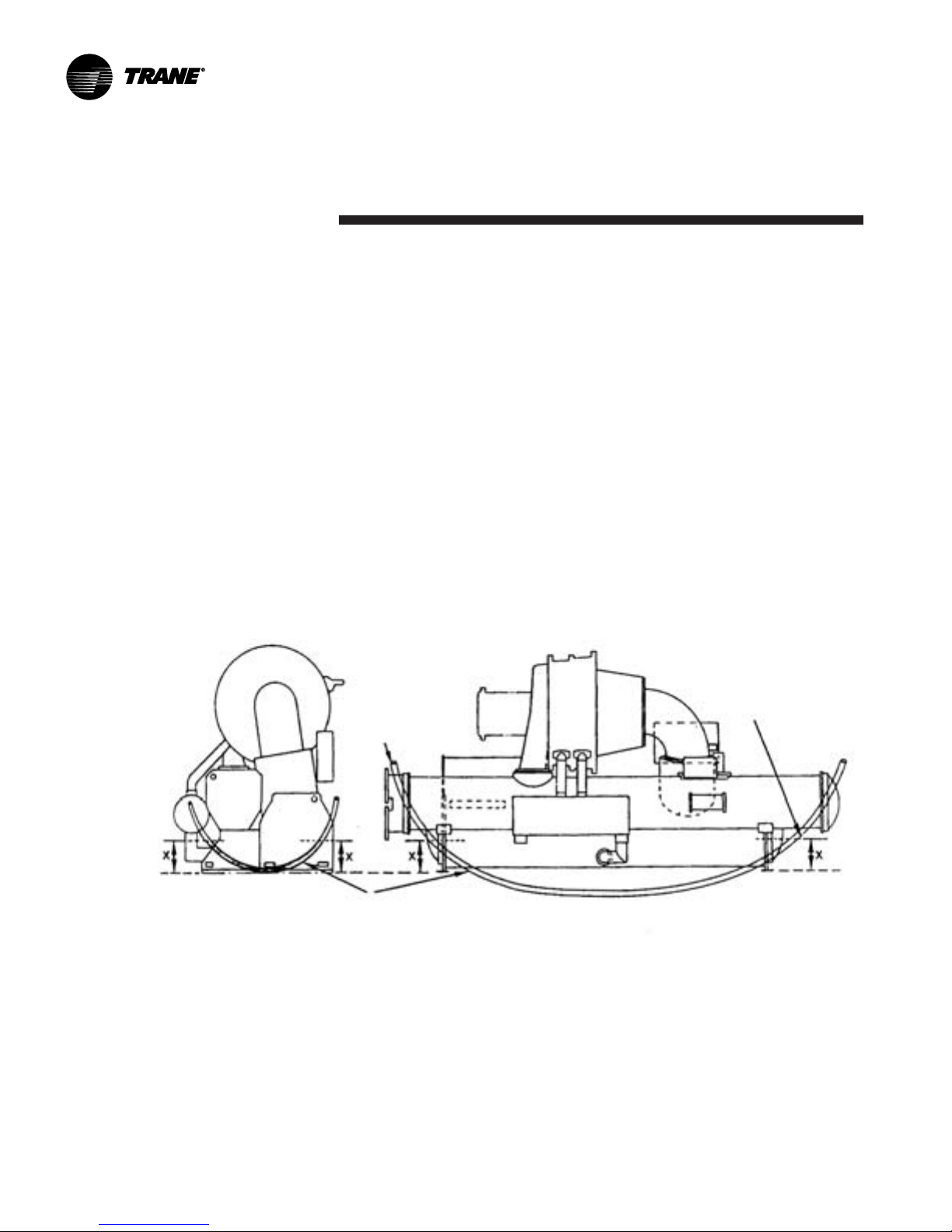
Figure 11 – Checking Unit Levelness
Raise chiller at one
end to align match
marks with water
level.
3. Fill the tube with water until the
level aligns with the punch mark at
one end of the chiller; then check
the water level at the opposite
mark.
If the water level does not align
with the punch mark, use fulllength shims to raise one end of
the chiller until the water level at
each end of the tube aligns with
the punch marks at both ends of
the chiller
4. Once the unit is level across its
length, repeat Steps 1 through 3 to
see if unit is level across the width.
5. If isolation pads have been used,
shim the center support.
Measure and mark
an equal distance
up from each
chiller foot.
Clear Plastic Tube
(Fill tube with water to punch mark.)
24
CDHF-SVN01B-EN
 Loading...