

Page 1

Installation
Operation
Maintenance
CLCH
QuantumClimate Changer
Air Handling Units
CLCH-SVX05A-GB
Page 2

CLCH-SVX05A-GB
General
Information
©American Standard Inc. 2002
Foreword
These installation, operation, and
maintenance instructions are given as a
guide to good practice in the installation,
commissioning into service, operation,
and periodic maintenance by the user, of
CLCH Air Handling Units. They do not
contain the full service procedures
necessary for the continued successful
operation of this equipment. The services
of a qualified service technician should be
employed through the medium of a
maintenance contract with a reputable
service company.
Warranty
Trane’s standard warranty covers the
equipment. It does not cover damage due
to misuse, lack of maintenance, or failure
to comply with the manufacturer's
instructions or recommendations.
Receiving/Handling
On arrival, inspect the unit before signing
the delivery note. Specify any damage on
the delivery note, and send a registered
letter of protest to the last carrier of the
goods within 72 hours of delivery. Notify
the local Trane sales office at the same
time. The unit should be totally inspected
within 15 days of delivery. If any
concealed damage is discovered, stop
unpacking the shipment. Take photos of
the damaged material if possible. Notify
the carrier immediately by phone and
registered mail. Notify the local Trane
sales office. Concealed damage must be
reported within 15 days of delivery.
About This Manual
Warnings appear at appropriate places in
this instruction manual. Your personal
safety and the correct operation of this
machine require that you follow the
warnings carefully. The manufacturer
assumes no liability for installations or
servicing undertaken by unqualified
personnel.
About The Unit
The information contained in this manual
applies to units designated CLCH
Page 3

4
3
Contents
5
7
9
18
23
1. Introduction
2. Delivery Check On Arrival/Off-Loading
and Movement To The Site
3. Foundations and Erection
4. Assembly and Installation
5. Commissioning Procedure
6. Maintenance
7. Troubleshooting
15
CLCH-SVX05A-GB
Page 4

CLCH-SVX05A-GB
4
1. Introduction
Please pay particular attention to the
instructions on the unit in accordance with
the identification label, assembly
drawings, and special warnings or advice
labels.
Page 5

CLCH-SVX05A-GB
5
2. Delivery Check On
Arrival/Off-Loading and
Movement To The Site
2.1 Delivery Check
Check the delivery contents on arrival of
CLCH units in respect of completeness,
and note any damage which may have
occurred. In the event of any damage
being noted, a claim must be made by
return. Only by compliance with this
procedure is it possible to submit an
insurance claim. Any damage must be
noted on the delivery documentation,
dated and signed in the presence of the
delivery driver, and signalled by
registered letter to the last forwarder.
Claims in respect of obvious transport
damage or incompleteness of delivery
cannot be accepted in retrospect. In
the event of any complaints, please
notify the relevant Trane office
immediately, and in writing within 72
hours.
2.1.1. Identification
All Trane CLCH units are identified by the
sales number and manufacturer's works
order number given on the unit ID label.
Be sure to refer to the information given
on the unit identification label when
ordering replacement parts or requesting
service. The nameplate (see Figure 1) is
mounted on the fan-section access side,
and a manufacturer's plate (see Figure 2)
is fixed inside the fan section.
Figure 2 – Manufacturers Plate
2.2 Off Loading
A specific lifting method for offloading the
units is recommended as follows (see
Figure 3):
1) 52 mm-diameter lifting holes, or
certified lifting lugs, are provided on the
unit base frame.
2) ALL LIFTING POINTS in one axis of
the unit must be used when offloading
and moving the unit.
3) Slings and spreader bars are to be
provided by the rigger and attached to
ALL LIFTING POINTS.
4) The minimum rated lifting capacity
(vertical) of each sling and spreader
bar should be no less than the shipping
weight.
5) The unit must be lifted with care,
avoiding shock load by lifting the unit
slowly and evenly.
2.3 Moving To Position On
Site
Trane units are supplied in sections
modules, flat packed, or as a complete
unit, in accordance with the relevant
assembly drawings. Any necessary use
of force during unloading or movement of
the units must only be applied via the unit
base frame or shipping pallet.
NEVER LIFT THE UNITS BY COIL
CONNECTIONS OR BY ANY OTHER
PROTRUSIONS.
THE ROOF IS NOT DESIGNED TO BE
WALKED ON, BUT IF THIS IS
UNAVOIDABLE, ENSURE A MORE
EVEN WEIGHT DISTRIBUTION BY
THE USE OF BOARDS.
FAILURE TO DO SO MAY RESULT IN
SEVERE PERSONAL INJURY OR
DEATH.
WARNING
Figure 3
Figure 1 – Nameplate
ENSURE SLINGS DO NOT FOUL ON
UNIT PROTRUSIONS.
THE CENTRE OF GRAVITY WILL
VARY PER UNIT…POSITION THE
SLINGS AND SPREADER BARS
CAREFULLY TO COMPENSATE FOR
THIS.
FAILURE TO DO SO MAY RESULT IN
SEVERE PERSONAL INJURY OR
DEATH.
WARNING
Page 6

6
2. Delivery Check On
Arrival/Off-Loading and
Movement To The Site
2.4 Forklift Trucks
The forks must only be applied under the
unit base frame and not against the unit
base frame. The lift point should be as
near as possible to the centre of gravity
(see Figures 4 and 4a). In the case of
larger units the use of several forklift
trucks may be required.
2.4.1. Roller Movement
Units fitted with base frames may be
moved on roller trolleys or tubular rollers
(see Figure 5).
Figure 4
Figure 4A
Figure 5
CLCH-SVX05A-GB
Page 7

7
3. Foundations and
Erection
3.1 Foundation
When selecting and preparing the unit
site, follow these guidelines:
1. Ensure that the site can support the
total weight of the unit. Unit weight
figures only provide total gross weights
and do not include the additional
weight for water in any coils.
2. Confirm that the foundation of the
mounting platform is large enough to
include the unit dimensions plus
service plus service access.
3. The floor or foundation must be level
for correct coil drainage and
condensate flow.
4. Provide adequate lighting for
maintenance personnel to perform
maintenance duties.
5. When the unit is positioned on site,
there must be sufficient space around
the unit to ensure that correct operation
and effective maintenance can be
carried out. Figure 6 gives
recommended space allowances.
•
On the designated access side of the
unit, working areas must be equal to the
width of the unit, dimension “P.”
•
Allowance for coil connections,
dimension “C” must be dimension “P” +
200 mm.
•
A clear unobstructed area before and
after an air intake or discharge is
required to ensure correct air
movement. The width of the area must
be >= the width of the unit, and the
depth (dimension "L") must be >= 0.5 x
the overall unit height.
Complete reinforced concrete
foundations are suitable or strip
foundations may also be used (see
Figure 7).
In the case of strip foundations, concrete
or steel supports are permissible, but
support is required under breakpoints and
every 2 m along the unit base.
Figure 7 – Air Handling Unit Steels Foundation
Figure 6
L
P
C
CLCH-SVX05A-GB
Page 8

8
3. Foundations and
Erection
Figure 8 – Air Handling Unit Plinth Foundation
FAILURE TO PROVIDE A LEVEL
PLINTH OR SUPPORT WILL RESULT
IN DOORS JAMMING AND AIR LEAKS
FROM THE CASING.
3.2 Erection
To minimize noise transmission,
insulation material such as cork slabbing
(TICO pads) may be placed between the
unit base and the foundation (see Figure
8).
IMPORTANT
CLCH-SVX05A-GB
Page 9

9
4. Assembly and
Installation
4.1 Break Point and General
Unit Assembly
Instructions
Ensure that all the air-handling unit
sections are positioned in the correct
order.
Each section will display a unit drawing
with its position OUTLINED.
1. Each of the unit sections should be
placed on a level foundation and within
200 mm of its adjoining section.
2. Remove any supports and bracing
which are supplied with the unit for
transport. All such supports will be
clearly marked:
“FOR TRANSPORT ONLY –
REMOVE BEFORE ASSEMBLY”
3. Remove 4 M6 fixing bolts (A) from the
protruding portion of the 4 framework
joining bars (see Figure 9), then loosen
the remaining 4 bolts that are located
on the fixed side of the break point
joining bars.
Pull together the sections of the unit,
ensuring that the joiner bar in each of
the 4 corners is fitted into its adjoining
section and the plastic “T” section
sealing strip locates over the adjoining
panel.
The 52-mm diameter holes provided in
the unit base frame should be used to
manoeuvre the sections together.
Greased skid plates will greatly assist
the whole assembly operation.
4. Secure the break point joint externally
by replacing the 4 M6 bolts and
washers, which were previously
removed in step (3). Retighten the 8
bolts located on both sides of the break
point joint.
Where applicable, complete the
assembly of the unit as follows:
4.1.3. Fan sections
Bolt the outlet of the fan to the flexible
connection using the M8 bolts provided.
4.1.4. Damper sections
Pop-rivet through the damper spigot and
the adjoining plastic “J” section into the
adjacent fixed panel using 5-mmdiameter rivets.
4.1.5. Coil sections (with drip pans)
Fix through the top of the drip pan into the
box section using the self-drilling screws,
which are provided. Then seal along all
joints with a waterproof “silicone” based
sealant. We recommend “Siloflex.”
4.1.6. Weatherproof roofs
Slide on the “Doby” cleats, which are
provided, and then fix in position at the
ends with the cleat clips on the roof return
edge using 5mm diameter rivets.
2
1
2
1
CLCH-SVX05A-GB
Figure 9
Figure Notes:
1. Part 1
2.Part 2
3. Break Point
4. Bolts “A”
5. Fixed bolts
6. 52 mm diameter holes
7. 8 x M6 bolts (2 per join)
1
2
5
4
7
6
1
2
3
Page 10

10
4. Assembly and
Installation
4.2 Stacked Units (Top and
Bottom)
Lower the top unit into position on top of
the bottom unit, taking care not to
damage the sealing gaskets.
Fit the self-tapping screws to the fixing
brackets, which are already positioned on
the top edge of the bottom unit,drilling into
the top unit section (10A) or base frame
(10B) depending on product, in order to
secure the top unit to the bottom unit (see
Figure 10).
Fix into position any internal joining strips
and/or brackets that are provided, and
then seal up any common sections in the
top and bottom units.
4.2.1. Stacked units (Side by Side)
Manoeuvre the two units into their correct
positions, taking care not to damage any
sealing gaskets.
Fix through the fixing brackets which are
located at both ends of the units in order
to secure the units together. Also fix into
position any base frame, unit end, and
roof joining brackets that are provided.
Fix into position any internal joining strips
and/or brackets that are provided, and
then seal up any common sections in
both of the units.
If you require further assistance or have
any questions please contact your local
Trane sales office.
4.3 Assembly of Flatpacked
Units
The unit is fully assembled in the factory
on a flat and level surface. Prior to
disassembly for flat packing (see Figure
11) all items are marked
alphanumerically. All items marked “A”
are joined at the fixing indicated at this
point. These markings are on labels on
internal surfaces so they are not evident
upon completion. DO NOT remove labels
until assembly is complete.
We would recommend opening one unit
at a time to avoid confusion.
Figure 10 A/B
Figure Notes:
1. Self tapping screws
2. Bottomframework of TOP unit
3. Fixing bracket
4. Top framework of BOTTOM unit
Figure 11
CLCH-SVX05A-GB
Figure 10A
Figure 10B
1
2
4
3
Page 11

11
4. Assembly and
Installation
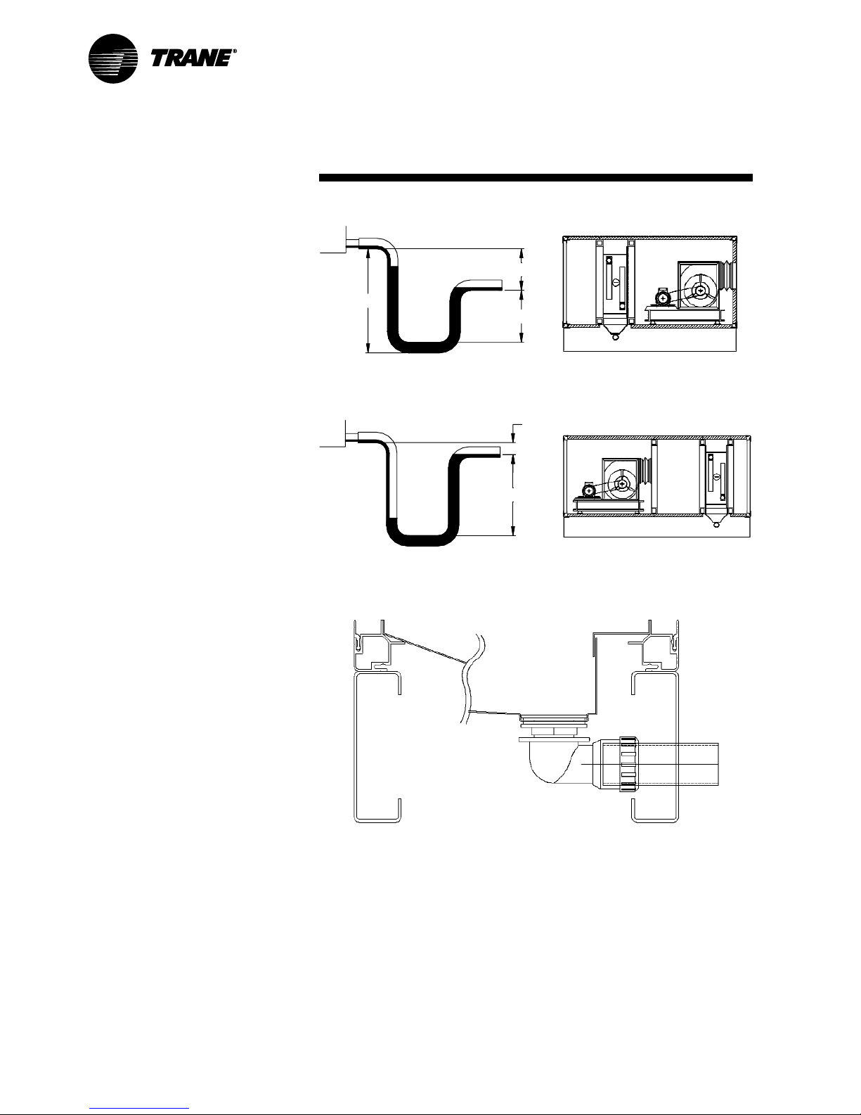
4.4 Condensate Drain From
Drain Pan
Correctly-sized traps must be fitted
immediately after the drip pan outlet (see
Figures 12, 13 and 14).
An “air break,” by means of a tun dish,
must be fitted immediately after the trap.
Figure 12 – Typical Air Conditioning Plant Drain
Figure 12 Notes:
1. Cooling coil, humidifier, or chilled battery.
2. Vented drainage stack
3. Fall
4. Air break
5. Swept connection
6. Trap with water seal (with filling cap)
7. Open tun dish or floor gully/channel
8. Trap with water seal
1
2
3
4
3
5
8
7
6
CLCH-SVX05A-GB
Page 12
12
4. Assembly and
Installation
Figure 13 – Negative Pressure Trap (Draw Through)
Figure 14 – Positive Pressure Trap (Blow Through)
Figure Notes:
1. 25 mm for each 250 Pa of maximum
negative static pressure + 25 mm
2. 0.5 x dimension 1
3. Dimensions 1 + 2 + pipe diameter +
insulation
Figure Notes:
1. Minimum of 12 mm
2. 12 mm + maximum total static pressure
Figure 15 – Drip Pans
1
1
2
2
3
4.5 Drip Pans
A UPVC elbow and 1-1/2" [38 mm]
diameter (internal dimension) discharge
pipe is supplied as standard (3.2 mm wall
thickness).
A copper elbow and 35 mm diameter
discharge pipe is available as an option
(1.2 mm wall thickness).
Drip pans (see Figure 15) are not
designed to be walked on.
CLCH-SVX05A-GB
Page 13

13
4. Assembly and
Installation
4.6 Pipework Layout
A correct pipework installation is essential
for trouble-free coil operation. Figure 16
gives an example for piping water coils.
(The diagram does not limit the type of
control system used.)
All pipework must be supported
independently from the coils.
All connections must be made in such a
way that the expansion and contraction of
pipes do not impose forces on the coil
headers. Failure to do so may result in
coil damage.
Figure 16 – Fluid Pipework
Figure Notes:
1. Gate Valve
2. Automatic or Manual Drain and Vent
3. Automatic Three-Way Valve
4. Main Supply Water
5. Main Return Water
CLCH-SVX05A-GB
Page 14

14
4. Assembly and
Installation
4.7 Water Coils
The air venting of the system should not
be carried out through the coil. Air venting
should be allowed for in the pipework and
any coil vent should be for the sole
purposes of venting the coil itself. When
incoming air temperature may be colder
than 0°C, do not modulate the water flow
as this may cause freezing and damage
to the coil.
4.7.1. Steam Coils
Overhead condensate-return systems
should not be used; allow for vacuum
breakers as close as possible to the coil.
Include a float or thermodynamic trap on
all steam coils (following trap
manufacturer recommendations).
CORRECT TRAPPING IS VERY
IMPORTANT. FAILURE TO PROPERLY
REMOVE CONDENSATE WILL
RESULT IN WATER HAMMER AND
POSSIBLE COIL FAILURE.
4.7.2. Refrigerant Coils
Refrigerant pipework installation requires
specialist design and trained refrigeration
engineers for correct installation.
If you have any queries, please contact
your local Trane sales office.
4.8 Electrical Connections
The electrical work must be carried out in
accordance with all international, national,
and local regulations.
Electrical connections passing through
the casing to the fan motor should be
carried out in a flexible conduit.
Cables passing through the casing must
be made with a gland or grommet.
All wiring to other accessories must be
carried out in the same manner.
PLEASE REFER TO THE UNIT
MOUNTED CONTROLS IOM.
Motor connection details are contained in
the cover of the motor terminal box.
If you have any queries, please contact
your local Trane sales office.
4.8.1. Duct Connections
To reduce noise transmission, the fitting
of an intermediate flexible connection of
at least 140 mm width, between the
ducting and the unit flange, is
recommended. This should be
unstressed when initially positioned.
Compliance with the Codes of Practice in
duct assembly and acoustic layout are
essential, to ensure the best possible
performance of the unit whilst avoiding
excessive pressure loss in the duct
system and minimizing airstream noise.
4.8.2. Motor Connection
Safety measures need to be taken on site
against overload, short circuit, high or low
voltage, and excessively high ambient
temperatures.
Special care must be taken in the
connection of motors, especially if twospeed motors are supplied with the unit.
The connection must be carried out in
accordance with the nameplate and the
wiring diagrams as shown on the inside
of the motor terminal box.
Following the connection of the motor, a
test run must be carried out in order to
check motor performance and rotational
direction.
Please see the section on commissioning
procedures for additional information.
IMPORTANT
CLCH-SVX05A-GB
Page 15
15
5. Commissioning
Procedure
5.1 Preparations
Initially the complete CLCH unit and all
components should be thoroughly
cleaned and all dust and other deposits
completely removed. The unit must be
maintained in a clean condition.
Prior to despatch, each unit is thoroughly
checked. Nevertheless, as part of the
commissioning procedure, it is imperative
to recheck certain items as listed below.
Some of the settings on the unit may
have changed during transport and
during the installation process.
Make sure that the dampers move freely
and that all transport packing has been
removed.
Table 1 – Torque Settings
Bush Size 1008 1108 1210 1610 2012 2517 3020 3525 4030 4535 5040
Screw Tightening Torque (Nm) 5.6 5.6 20 20 30 50 90 115 170 190 270
Screw Details Quantity 22222 223 3 33
Size (BSW) 1/4" 1/4" 3/8" 3/8" 1/16" 1/2" 5/8" 1/2" 5/8" 3/4" 7/8"
Hexagon Socket Size (mm) 335556810121414
Large End Diameter (mm) 35.0 38.0 47.5 57.0 70.0 85.5 108.0 127.0 146.0 162.0 177.5
Approximate Mass (kg) 0.1 0.1 0.2 0.3 0.7 1.5 2.7 3.8 5.6 7.5 11.1
Fenner is a registered trademark of J H Fenner & Co Ltd.
Taper Lock and P B (Precision Built) are registered trademarks of F P T Group.
Reproduced with permission of F P T Group.
5.2 Fan/Motor
Check that the fan revolves freely by
turning the impeller manually.
Check the tension of the fan belt and the
alignment of the pulleys (see the section
on maintenance for additional
information).
Check that the grub screws in the taper
locks are tightened to the torque settings
in Table 1.
Check the motor connections and make
sure that the correct voltage supply is
being used.
Where a standby motor has been
supplied, only connect one motor to the
power source.
Please refer to the individual supplier's
installation, operation, and maintenance
manual for additional information.
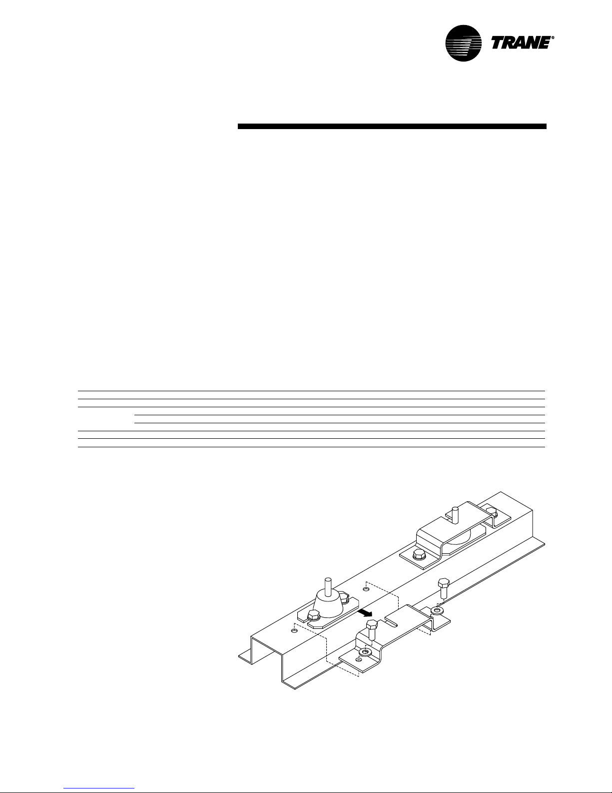
5.3 Anti-Vibration Mount
Brackets
For transport, the fan/motor base antivibration mounts are fitted with retaining
brackets. These must be removed before
the unit is started (see Figure 17).
Figure 17 – Anti-Vibration Transport Bracket Removal
CLCH-SVX05A-GB
Page 16

5.7 Steam Operating Filling
Open the system air vent and drain valve
gradually on the condensate drain.
Open the steam valve a small amount
until steam penetrates through the
condensate drain valve and air vent.
Close the condensate drain valve and air
vent, and open the steam valve fully.
Vent regularly during operations.
If the installation is occasionally on
standby, condensate must not be
allowed to remain in the pipes on
account of freezing and corrosion risk.
To prevent overheating coils, the fan
stop must be delayed by 3 to 5
minutes after the steam valve has
been closed.
5.8 Electric Heaters
Electric heaters are fitted with thermal
cutouts. These must be connected to the
control panel on site, to prevent
overheating of the unit. The fan is fitted
with an overrun for a period of 3 to 5
minutes.
5.9 Filters
Check that the filters are correctly fitted,
with the working side of the filter exposed
to the contaminated air stream. Refer to
the data sheets with regard to the
clean/dirty pressure drop readings.
Ensure that any pressure testing devices
are fitted correctly and that they are
zeroed to the right values (clean/dirty
pressure drops).
Over time, the liquid in the pressuretesting device will fade.
16
5. Commissioning
Procedure
5.4 Unit Connections
All electrical, water, and ductwork
connections of the unit must be
completed by a qualified person.
To avoid damaging the coil
connections it is essential to grip the
hexagonal pipe connection whilst
applying counter pressure to tighten
the joint (see Figure 18).
Figure 18
Completely stress-free connections are
essential. The pipework of the coils
should be arranged to facilitate easy
removal of the coil for any required
maintenance purposes.
5.5 Coils
Check that the coil connections and
valves are not leaking. If there are leaks,
rectify the problem.
Cooling medium refrigerant Freon.
When direct condensers or air-cooled
condensers are fitted, the system
must be filled with refrigerant.
In this case a refrigerant engineer
must carry out the installation and
pipework.
5.6 Operating
In general, heating and cooling coils
should be filled with water containing
additives to protect against freezing and
corrosion:
Open the air vents.
Open the water supply valve a little so
that the heater battery fills slowly. This
avoids thermal stress.
As soon as the battery heater is full, close
the air vent.
Open the water valve fully and switch on
the fan.
Finally, the entire pipe system must be
completely vented.
All traps connected to the AHU drip trays
must be primed prior to operating the unit.
CAUTION
IMPORTANT IMPORTANT
CLCH-SVX05A-GB
Page 17

17
5. Commissioning
Procedure
5.10 Humidifiers and Water
Quality
The humidifier water supply quality is very
important to ensure correct operation.
The use of incorrectly treated or
untreated water in this equipment may
result in scaling, erosion, corrosion,
algae, or slime.
The services of a qualified water
treatment specialist should be
engaged to determine what treatment,
if any, is required. The Trane warranty
specifically excludes liability for
corrosion or deterioration. Trane
assumes no responsibility for
equipment damage or failure that
results from the use of treated water,
or saline, or brackish water.
Please refer to the individual supplier's
installation, operation, and maintenance
manual for additional information.
5.11 Gas Burners
The gas burner supplier will commission
this equipment when installed on site.
Please refer to the individual supplier's
installation, operation, and maintenance
manual for additional information.
5.12 HEPA Filters
The HEPAfilter section is supplied with
complete front withdrawal framework.
HEPAfilters are supplied in original
packaging with the unit.
A specialist sealing company must be
employed to seal up the filter framework,
fit and seal the HEPAfilters, and complete
a DOP test or equivalent.
5.13 Inverters
The inverter needs to be set up and run in
accordance with the supplier's IOM.
Please refer to the individual supplier's
installation, operation, and maintenance
manual for additional information.
5.14 Controls
See controls IOM and wiring diagrams.
Please refer to the individual supplier's
installation, operation, and maintenance
manual for additional information.
5.15 Test Run
Following the completion of all
preparatory work, the unit is started up for
a test run.
To conduct a test run that involves the
measurement of motor and fan
performance, the unit must be
connected to the complete installation.
All access doors must all be closed to
avoid pressure loss in the installation,
which may result in motor damage.
Before staring the fan, open ALL
dampers. The fan must not be started
if the dampers are closed. When
starting the fan, open the dampers.
The fan should not work against
closed dampers.
After switching on, check that the
direction of the rotation is correct. In
addition, the running power consumption
should be checked on all phases and
compared with the power data on the
nameplate. If the running power is too
high, there is probably a faulty connection
and the unit must be switched off
immediately. Check the fan and motor
bearings for undue noise. Measure the air
volume and external pressure.
The following situations may arise:
1. The air volume is lower, as the system
pressure is much higher than
designed.
2. The air volume is higher, as the system
pressure is much lower than designed.
Increasing the fan speed should only
be carried out after careful study of the
measured point on the appropriate fan
curve.
In extreme cases exchanging the motor,
fan and drive may be necessary.
The adjustment of variable belt-drive
pulleys is carried out with the system at
rest, ensuring that the system is not
restarted unexpectedly. Remove the
pulley safety screws and turn through half
of the pulley circumference to carry this
out. Then retighten the screws and
readjust the pulley belt tension.
Following any change in the pulley ratio,
the motor power consumption must be
rechecked.
The nominal output rating quoted on the
nameplate must not be exceeded.
In all cases of airflow not conforming to
the specifications, please contact your
sales office.
CAUTION
IMPORTANT
IMPORTANT
IMPORTANT
CLCH-SVX05A-GB
Page 18

18
6. Maintenance
The maintenance interval periods are
stated, guidelines only. Any large
deviations in the pattern of usage may
necessitate further maintenance
attention.
During maintenance operations the
unit must be completely isolated and
precautions taken to prevent any
premature restart.
6.1 Fan
If the fan/motor assembly is going to be
stored for over two weeks before use, the
fan should be rotated by hand at weekly
intervals to avoid bearing damage.
If storage will be over one month it is
recommended that the belts be
slackened as well.
Check for soiling, damage, corrosion, and
any tendency to bind. Clean as
necessary.
Check that the flexible connections are
securely fixed.
Check the function of all antivibration
mounts.
Check for any obstructions or blockages
of all the air intakes and discharges.
Check the traps for leaks or blockages
and prime as necessary.
6.2 Bearing Test
Check that the fan bearing is tightened
and is not unduly noisy, by sounding it
using a metal bar as a conductor.
Where a belt guard has been supplied,
check that it is fitted correctly.
If there is any irregular noise or knocking,
renew both bearings. Fan bearings are
greased for life, but larger units with
standard bearings require annual
lubrication. These have grease line
extensions. In the case of extreme
running conditions, lubricate in
accordance with the following
recommendations:
Recommended lubricants;
ALVANIA
GREASE 3 (SHELL)
MOBILUX 3 (MOBIL)
BEACON 3 (ESSO)
SKF 28 (BALL BEARING
GREASE)
Do not overlubricate bearings.
Excessive pressure caused by
overlubrication can displace bearing
grease seals or cause grease to
overheat the bearing, resulting in
premature bearing failure.
6.3 Motor
Check the state of cleanliness of the
motor and clean it if necessary. Check the
noise level of the motor bearing by
listening to it with a metal conductor. If
there is any irregularity or undue noise,
the bearing should be changed or the
motor replaced.
6.4 Belt Drive
Belts that are split or have frayed edges
or any other signs of damage must be
replaced. Rubber shred on the fan
section floor is a sign of abnormal wear.
6.5 Belt Drive Tensioning
Tensioning of the drive belt is achieved by
moving the motor in relation to the fan
(see Figure 19).
The motor is moved on slide rails.
Figure 19
Figure Notes:
1. Slide rails
2. Lock nut
3. Tensioning screw
4. Tensioning pad
Loosening the motor retaining bolt and
then turning the tensioning screw carries
out the adjustment. It is important to
maintain the precise alignment of the
pulleys.
This should be checked with a straight
edge following each adjustment.
Following completion of the adjustment,
retighten the motor retaining bolts.
The belt tension should be checked by
using a proprietary instrument such as
the Browning belt-tension checker.
The belt drive must be retensioned
after the first 10 hours of operation.
The high performance of Fenner
Precision Built belts requires correct
tension; we recommend using the Fenner
Belt Tension Indicator.
IMPORTANT
IMPORTANT
CLCH-SVX05A-GB
Page 19

19
6. Maintenance
Method of Belt Tensioning using
Fenner Belt Tension Indicator.
1. Calculate the deflection distance in
mm, on a basis of 16 mm per meter, of
centre distance (see Figure 20).
Centre distance (m) x 16 = deflection
(mm).
2. Set the lower marker ring at the
deflection distance required in mm on
the lower scale.
3. Set the upper marker ring against the
bottom edge of the top tube.
4. Place the belt tension indicator on the
top of the belt at the centre of the span.
Apply a force at right angles to the belt,
deflecting it to the point where the
lower marker ring is level with the top of
the adjacent belt.*
5. Read off the force value indicated by
the top edge of the upper marker ring.
6. Compare this force to the kgf value
shown in Table 2.
*NOTE:
For a single belt drive, a straight edge
should be placed across the two pulleys
to act as a datum for measuring the
amount of deflection.
Fenner is a registered trademark of J H Fenner & Co Ltd.
Taper Lock and P B (Precision Built) are registered trademarks of F P T Group.
Table 2 – Tensioning Forces (Force required to deflect belt 16 mm per metre of span)
Belt Section SPZ SPA SPB SPC Z A B C
Small Pull Diameter (mm) 56 100 80 140 112 236 224 375 56 80 125 200
to to to to to to to to to to to to
95 130 132 200 224 315 355 560 100 140 200 400
Newton (N) 13 20 25 35 45 65 85 115 5 10 20 40
to to to to to to to to to to to to
20 25 35 45 65 85 115 150 7.5 15 30 60
Kilogram-Force (kgf) 1-3 2-0 2-5 3-6 4-6 6-6 8-7 11-7 0-5 1-0 2-0 4-1
to to to to to to to to to to to to
2-0 2-5 3-6 4-6 6-6 8-7 11-7 15-3 0-8 1-5 3-1 6-1
Deflection in mm Deflection Force in kg
Reproduced with permission of F P T Group.
If the measurement force falls within the
values given, the drive should be
satisfactory. A measured force below the
lower value indicates undertensioning.
A new drive should be tensioned to a
higher value to allow for the normal drop
in tension during the running-in period.
After the drive has been running for 30
minutes, the tension should be checked
and readjusted to the higher value, if
necessary.
Figure 20
Fenner is a registered trademark of J H
Fenner & Co Ltd.
Taper Lock and P B (Precision Built) are
registered trademarks of F P T Group.
Reproduced with permission of F P T
Group.
Figure 20 Notes:
1. 1/2 Centres
2. Force
3. 16 mm deflection / 1 m of centre distance
4. Centre Distance
Damage to the motor and fan bearings
can result from the belt being
overtensioned.
In the event of the belt adjustment
being too slack, undue wear and
slippage may result.
1
2
3
4
IMPORTANT
CLCH-SVX05A-GB
Page 20

20
6. Maintenance
6.6 Belt Replacement
Where a belt guard has been supplied,
please remove the belt guard before
starting work.
To change the belt (or belts), first move
the motor towards the fan by a sufficient
amount to enable the old belts to be
taken off the pulleys and the new belts to
be put on.
If the belt drive has more than one belt,
replace all belts at the same time (see
Figure 21). In such cases, use matched
belts, such as sets in which all belts are
exactly the same lengths.
Tension the belts as per Section 6.5.
Figure 21
Fenner is a registered trademark of J H
Fenner & Co Ltd.
Taper Lock and P B (Precision Built) are
registered trademarks of F P T Group.
Reproduced with permission of F P T
Group.
TO INSTALL
1. Remove the protective coating from
the bore and outside of bush, and bore
of hub. After ensuring that the mating
tapered surfaces are completely clean
and free from oil or dirt, insert bush in
hub so that holes line up.
2. Sparingly oil thread and point of grub
screws, or thread and under head of
cap screws. Place screws loosely in
holes threaded in hub.
3. Clean shaft and fit hub to shaft as one
unit and locate in position desired,
remembering that bush will nip the
shaft first and then hub will be slightly
drawn onto the bush.
4. Using a hexagon wrench, tighten
screws gradually and alternately to the
torques shown in Table 3.
5. Hammer against large end of bush,
using a block of sleeve to prevent
damage. (This will ensure that the bush
is seated squarely in the bore.) Screws
will now turn a little more. Repeat this
alternate hammering and screw
tightening once or twice to achieve
maximum grip on the shaft.
6. If a key is to be fitted, place it in the
shaft keyway before fitting the bush. It
is essential that it is a parallel key and
side fitting only, and has TOP
CLEARANCE.
7. After the drive has been running under
load for a short time, stop and check
tightness of the screws.
8. Fill empty holes with grease to exclude
dirt.
TO REMOVE
1. Slacken all screws by several turns.
Remove one or two according to the
number of jacking off holes. Insert
screws in jacking off holes after oiling
thread and point of grub screws or
thread and under head of cap screws.
2. Tighten screws alternatively until bush
is loosened in hub and assembly is
free on shaft.
3. Remove assembly from shaft.
Table 3 – Torque Settings
Bush Size 1008 1108 1210 1610 2012 2517 3020 3525 4030 4535 5040
Screw Tightening Torque (Nm) 5.6 5.6 20 20 30 50 90 115 170 190 270
Screw Details Quantity 22222 223 3 33
Size (BSW) 1/4" 1/4" 3/8" 3/8" 1/16" 1/2" 5/8" 1/2" 5/8" 3/4" 7/8"
Hexagon Socket Size (mm) 335556810121414
Large End Diameter (mm) 35.0 38.0 47.5 57.0 70.0 85.5 108.0 127.0 146.0 162.0 177.5
Approximate Mass (kg) 0.1 0.1 0.2 0.3 0.7 1.5 2.7 3.8 5.6 7.5 11.1
Fenner is a registered trademark of J H Fenner & Co Ltd.
Taper Lock and P B (Precision Built) are registered trademarks of F P T Group.
Reproduced with permission of F P T Group.
CLCH-SVX05A-GB
Page 21

21
6. Maintenance
6.7 Filter Sections
During system start-up, filters are likely to
become rapidly blocked.
Filter sections may be supplied with a
manometer, which gives a visual
indication of filter conditions and pressure
drop.
Throw-away panel filters and bag filters
must be replaced each time or when the
pressure drop reaches the indicated dirty
condition. Permanent synthetic or metallic
filters must be cleaned periodically.
Filters must be installed following the
direction of the airflow arrow.
Bag filter pockets should be vertical
when installed.
6.8 Coil Sections
In the event of coils being out of
commission for some time, it is advisable
to completely drain down the coil. On
each occasion when refilling is
undertaken, check that the coil is
effectively vented.
Periodic cleaning of the coils is required.
Dirty coils have increased airside
pressure drops and reduced heat
transfer, thus unbalancing the cooling or
heating system.
6.8.1. Cleaning
In the event that fin edges have been
bent, they can be straightened with the
aid of a coil comb.
The cleaning is carried out with the unit
intact using a powerful vacuum cleaner
on the dust-contaminated side. If the unit
is very dirty it will need to be removed and
wet cleaned.
If required, soft cleaning brushes may be
used ensuring that the heat exchanger
fins are not damaged.
6.8.2. Frost protection
Check that frost protection is working
before the commencement of each winter
period. Ensure that the frost sensor is
correctly installed and fitted and is
working within the correct temperature
range.
6.8.3. Drop eliminator
Check the cleanliness of the droplet
separator section and the blades
annually. If the blades are dirty, remove
and clean them. Contamination can result
in damage through water droplets in the
system and to a reduction in the system's
performance. Ensure that the blades are
correctly repositioned and that they are
not distorted.
6.8.4. Steam heater coils
In the case of steam heater batteries,
arrange for automatic steam shutoff when
the unit is at rest, and check the function
of the fan overrun in this context.
6.8.5. Direct expansion coils
Never use hot water or steam to clean
these coils. During normal operation, the
fin block must not ice up. If this occurs,
check the refrigeration system.
6.9 Electric Heaters
Check the heater for any dirt
accumulation. If required, clean the
heating elements with a soft brush. Check
safety controls and fan overrun controls.
6.10 Steam Humidifier
Maintain in accordance with the
manufacturer directions. The following
details are general purpose instructions:
Check the steam distributor and ensure
there are no undesirable deposits.
Check that the steam feeds do not leak.
Check that the condensate drain is
functioning.
6.10.1. Evaporative Humidifier
Any evaporative modules that are
strongly encrusted with calcium deposits
should be replaced. Trane cannot be
responsible for the proper cleaning of
evaporative humidifiers.
In order to avoid excess clogging of the
evaporative humidifiers, it is advisable to
interlock the spray pipe operation with the
fan operation.
6.11 Dampers
Check for dirt deposits, damage, or signs
of corrosion. Clean with high-pressure air
or with a steam jet.
6.12 Sound Attenuators
Silencer modules are basically
maintenance free. Within the framework
of wider maintenance programmes,
check for any dust deposits and vacuum
as necessary.
6.13 Weather Louvres/
Hoods
Check for any obstructions or blockages
in all of the air intakes and discharges.
6.14 Plate Heat Exchangers
Plate type heat exchangers are
aluminum; their service life is virtually
unlimited. Maintenance is limited to
cleaning operations. Clean the
condensate drain, check the trap, and top
up as necessary.
Any accumulation of fibres or dust at the
exchanger point-of-entry may be
removed with a brush or vacuum.
Any oil or greasy deposits must be
removed. If a bypass is fitted, maintain as
you would for dampers.
6.15 Heat Wheel
The drive unit should be maintained in
line with the manufacturer
recommendations. The construction of
the matrix is such that it is virtually
completely self-cleaning. The rotor may
be cleaned with pressurized air, water, or
steam jet and domestic detergents as
necessary.
IMPORTANT
CLCH-SVX05A-GB
Page 22

22
6.16 Maintenance Plan for Air Handling Units
The following table (see Table 4) gives recommended maintenance intervals for the CLCH unit. Intervals are based upon normal
running conditions, in a moderate climate, and assuming 24-hour running.
Units operating outside these guidelines may require shorter or longer maintenance intervals.
Table 4 – Recommended Maintenance Intervals
Component Check the Following Weekly Monthly 3-6 Monthly Annually
(see section) (see section) (see section) (see section)
Fan / Motor Fan In General Yes (6.1)
For Corrosion Yes (6.1)
Flexible Connection Yes (6.1)
Anti-Vibration Mounts Yes (6.1)
Inlet Guide Vane Controller Yes
Drainage Yes (6.1)
Fan Bearing Yes (6.2)
Motors In General Yes (6.3)
Motor Bearing Yes (6.3)
Belt Drive In General Yes (6.5)
Filters Panel Or Bag Filters Yes (6.7)
Roll Filters Yes
Absolute Filters Yes
Coils Fin Block Yes (6.8.1.)
Frost Protection Yes (6.8.2.)
Drainage Yes
Drop Eliminator Yes (6.8.3.)
Steam Coils Yes (6.8.4.)
Humidifiers Scaling Yes (6.10)
Condensate Drain Yes (6.10)
Dampers Dampers Yes (6.11)
Attenuators Scilencers Yes (6.12)
Inlet / Outlet Hoods And Louvers Yes (6.13)
Energy Recovery Components Plate Heat Exchangers Yes (6.14)
Thermal Wheel Yes (6.15)
Controls Control Box And Wiring Yes
6. Maintenance
CLCH-SVX05A-GB
Page 23

23
Symptom Probable Cause Recommended Action
Bearing is excessively hot Overtensioned belts. Retension belts.
No lubricant (plummer block type). Apply grease.
Overlubrication. Clean surface of grease and purge.
Misaligned bearing. Correct alignment and check that shaft is level.
Motor stalls Short circuit, phase to earth. Check line phases and terminal block connection.
Overloaded motor. Reduce system load, fan driven speed or increase motor
capacity.
Motor overheats Overloaded motor. Reduce load or replace with larger motor.
Motor fan damaged. Replace motor fan/clean.
Excessive vibration Poor pulley alignment. Check pulley alignment.
Transport brackets not removed. Remove items used for transport only.
Overtensioned belts. Retension belts.
Fan/unit vibration isolator collapsed. Replace vibration isolator.
Excessive motor noise Motor mounting bolts loose. Tighten motor mounting bolts.
Worn motor bearings. Replace bearings and seals.
Excessive fan noise Fan rubbing on inlet cone or guard. Remove item and repair.
Worn fan bearings. Replace bearings and seals.
Loose impeller. Retighten hub.
Premature belt wear Incorrect tension or alignment. Re-tension and align.
Dirt or grease on belts. Clean belts and pulleys; check for grease leaks.
Belts rubbing. Remove obstruction.
Odd belts being fitted. Replace with full set.
Filters collapsing Blocked with dirt. Change at advised dirty condition.
Air velocity too high. Check unit running conditions.
Filters wrong size. Replace with filter sizes as supplied
from Trane.
Damper seizing Blade bent. Repair or replace blade.
Spindle or mechanism loose. Tighten lever fixings.
Actuator loose. Refit actuator correctly.
Low coil capacity Incorrect airflow. Check fan operating conditions.
Incorrect water flow. Check water pumps, valves, and lines for obstructions.
Incorrect water temperature. Provide correct water temperature.
Coil tubes are blocked. Clean and unblock tubes.
Expansion valve not operating DX. Check sensing-bulb location and valve operation.
Poor refrigerant distribution DX. Check for blockage in distributor and tubes.
Leaking coil Header/exposed pipe damage. Repair damaged part.
Cracks in joints due to strain of Check support and alignment of pipework and rectify.
pipework on headers.
Swelling of joints due to frost. Check frost protection method and correct, improve.
(Water-hammer Steam Coils) Trapping of steam supply.
Drain pan overflow Incorrect hydraulic trapping. Resize/fit trap and check air break arrangement.
Blockage in trap. Clean trap and refit.
7. Troubleshooting
CLCH-SVX05A-GB
Page 24

Trane
An American Standard Company
www.trane.com
For more information contact
your local sales office or
e-mail us at comfort@trane.com
Literature Order Number
File Number
Supersedes
Stocking Location
Since The Trane Company has a policy of continuous product and product data improvement,
it reserves the right to change design and specifications without notice.
Only qualified technicians should perform the installation and servicing of equipment referred to in this publication.
Société Trane – Société Anonyme au capital de 61 005 000 Euros – Siège Social: 1 rue des Amériques – 88190
Golbey – France – Siret 306 050 188-00011 – RSC Epinal B 306 050 188
Numéro d’identification taxe intracommunautaire: FR 83 3060501888
CLCH-SVX05A-GB
SV-RF-CLCH-SVX05A-GB-1102
New
Colchester UK
 Loading...