

Page 1
Tracer CH530™
Chiller Control System
CGWN/CCUN 205-211
CGAN 209-214
User Guide
CG-SVU02B-E4
Page 2

General information
CG-SVU02B-E42
Foreword
These instructions are given as a
guide to good practice in the
installation, start-up, operation, and
maintenance by the user, of Trane
CH530 chiller control system on
CGWN/CCUN and CGAN 209-214
chillers. They do not contain full
service procedures necessary for
the continued successful operation
of this equipment. The services of a
qualified technician should be
employed through the medium of a
maintenance contract with a
reputable service company. Read
this manual thoroughly before unit
start-up.
Warnings and cautions
Warnings and Cautions appear at
appropriate sections throughout
this manual. Your personal safety
and the proper operation of this
machine require that you follow
them carefully. The constructor
assumes no liability for installations
or servicing performed by
unqualified personnel.
WARNING! : Indicates a potentially
hazardous situation which, if not
avoided, could result in death or
serious injury.
CAUTION! : Indicates a potentially
hazardous situation which, if not
avoided, may result in minor or
moderate injury. It may also be
used to alert against unsafe
practices or for equipment or
property-damage-only accidents.
Safety recommendations
To avoid death, injury, equipment or
property damage, the following
recommendations should be
observed during maintenance and
service visits:
1. Disconnect the main power
supply before any servicing on
the unit.
2. Service work should be carried
out only by qualified and
experienced personnel.
Reception
On arrival, inspect the unit before
signing the delivery note.
Reception in France only:
In case of visible damage: The
consignee (or the site
representative) must specify any
damage on the delivery note,
legibly sign and date the delivery
note, and the truck driver must
countersign it. The consignee (or the
site representative) must notify
Trane Epinal Operations - Claims
team and send a copy of the
delivery note. The customer (or the
site representative) should send a
registered letter to the last carrier
within 3 days of delivery.
Reception in all countries except
France:
In case of concealed damage: The
consignee (or the site
representative) must send a
registered letter to the last carrier
within 7 days of delivery, claiming
for the described damage. A copy of
this letter must be sent to Trane
Epinal Operations - Claims team.
Note: for deliveries in France, even
concealed damage must be looked
for at deli
very and immediately
treated as visible damage.
Page 3

General information
3CG-SVU02B-E4
Warranty
Warranty is based on the general
terms and conditions of the
manufacturer. The warranty is void
if the equipment is repaired or
modified without the written
approval of the manufacturer, if the
operating limits are exceeded or if
the control system or the electrical
wiring is modified. Damage due to
misuse, lack of maintenance or
failure to comply with the
manufacturer's instructions or
recommendations is not covered by
the warranty obligation. If the user
does not conform to the rules of
this manual, it may entail
cancellation of warranty and
liabilities by the manufacturer.
Maintenance contract
It is strongly recommended that you
sign a maintenance contract with
your local Service Agency. This
contract provides regular
maintenance of your installation by
a specialist in our equipment.
Regular maintenance ensures that
any malfunction is detected and
corrected in good time and
minimizes the possibility that
serious damage will occur. Finally,
regular maintenance ensures the
maximum operating life of your
equipment. We would remind you
that failure to respect these
installation and maintenance
instructions may result in
immediate cancellation of the
warranty.
Training
To assist you in obtaining the best
use of it and maintaining it in
perfect operating condition over a
long period of time, the
manufacturer has at your disposal a
refrigeration and air conditioning
service school. The principal aim of
this is to give operators and
technicians a better knowledge of
the equipment they are using, or
that is under their charge. Emphasis
is particularly given to the
importance of periodic checks on
the unit operating parameters as
well as on preventive maintenance,
which reduces the cost of owning
the unit by avoiding serious and
costly breakdown.
Page 4

Contents
CG-SVU02B-E44
General Information 2
Overview 5
DynaView Interface 6
Display Screens 6
TechView Interface 19
Software Download 20
Diagnostics 22
Page 5

Overview
5CG-SVU02B-E4
The Trane CH530 control system
that runs the chiller consists of
several elements:
• The main processor collects
data, status, and diagnostic
information and communicates
commands to the
LLID (for Low
Level Intelligent Device)
bus. The
main processor has an integral
display (DynaView).
•
LLID bus
. The main processor
communicates to each input and
output device (e.g. temperature
and pressure sensors, low
voltage binary inputs, analog
input/output) all connected to a
four-wire bus, rather than the
conventional control architecture
of signal wires for each device.
• The
communication interface
to
a building automation system
(BAS).
•A
service tool
to provide all
service/maintenance capabilities.
Main processor and service tool
(TechView) software is
downloadable from
www.Trane.com
. The process is
discussed later in this section
under TechView Interface.
DynaView provides bus
management. It has the task of
restarting the link, or filling in for
what it sees as "missing" devices
when normal communications
has been degraded. Use of
TechView may be required.
The CH530 uses the IPC3 protocol
based on RS485 signal technology
and communicating at 19.2 Kbaud
to allow 3 rounds of data per
second on a 64-device network.
Most diagnostics are handled by the
DynaView. If a temperature or
pressure is reported out of range by
a LLID, the DynaView processes this
information and calls out the
diagnostic. The individual LLIDs are
not responsible for any diagnostic
functions.
Note:
It is imperative that the CH530
Service Tool (TechView) be used to
facilitate the replacement of any
LLID or reconfigure any chiller
component
.
Controls Interface
DynaView (picture on cover)
Each chiller is equipped with the
DynaView interface. DynaView has
the capability to display additional
information to the advanced
operator including the ability to
adjust settings. Multiple screens are
available and text is presented in
multiple languages as factoryordered or can be easily
downloaded online.
TechView
TechView can be connected to the
DynaView module and provides
further data, adjustment
capabilities, diagnostics
information, downloadable
software, and downloadable
languages.
Page 6
DynaView Interface
CG-SVU02B-E46
The display on DynaView is a
1/4 VGA display with a resistive
touch screen and an LED backlight.
The display area is approximately
4 inches wide by 3 inches high
(102mm x 60mm).
CAUTION!
Equipment Damage! Putting
excessive pressure on the touch
screen could cause damage. It takes
less than 7 kg of force to break the
screen.
In this touch screen application, key
functions are determined
completely by software and change
depending upon the subject matter
currently being displayed. The basic
touch screen functions are outlined
below.
Radio Buttons
Radio buttons show 1 menu choice
among 2 or more alternatives, all
visible. The possible selections are
each associated with a button. The
selected button is darkened,
presented in reverse video to
indicate it is the selected choice. The
full range of possible choices as
well as the current choice is always
in view.
Spin Value Buttons
Spin values are used to allow a
variable setpoint to be changed,
such as leaving water setpoint. The
value increases or decreases by
touching the (+) or (-) arrows.
Action Buttons
Action buttons appear temporarily
and provide the user with a choice
such as Enter or Cancel.
File Folder Tabs
File folder tabs are used to select a
screen of data. The tabs are in 1 row
across the top of the display. The
user selects a screen of information
by touching the appropriate tab.
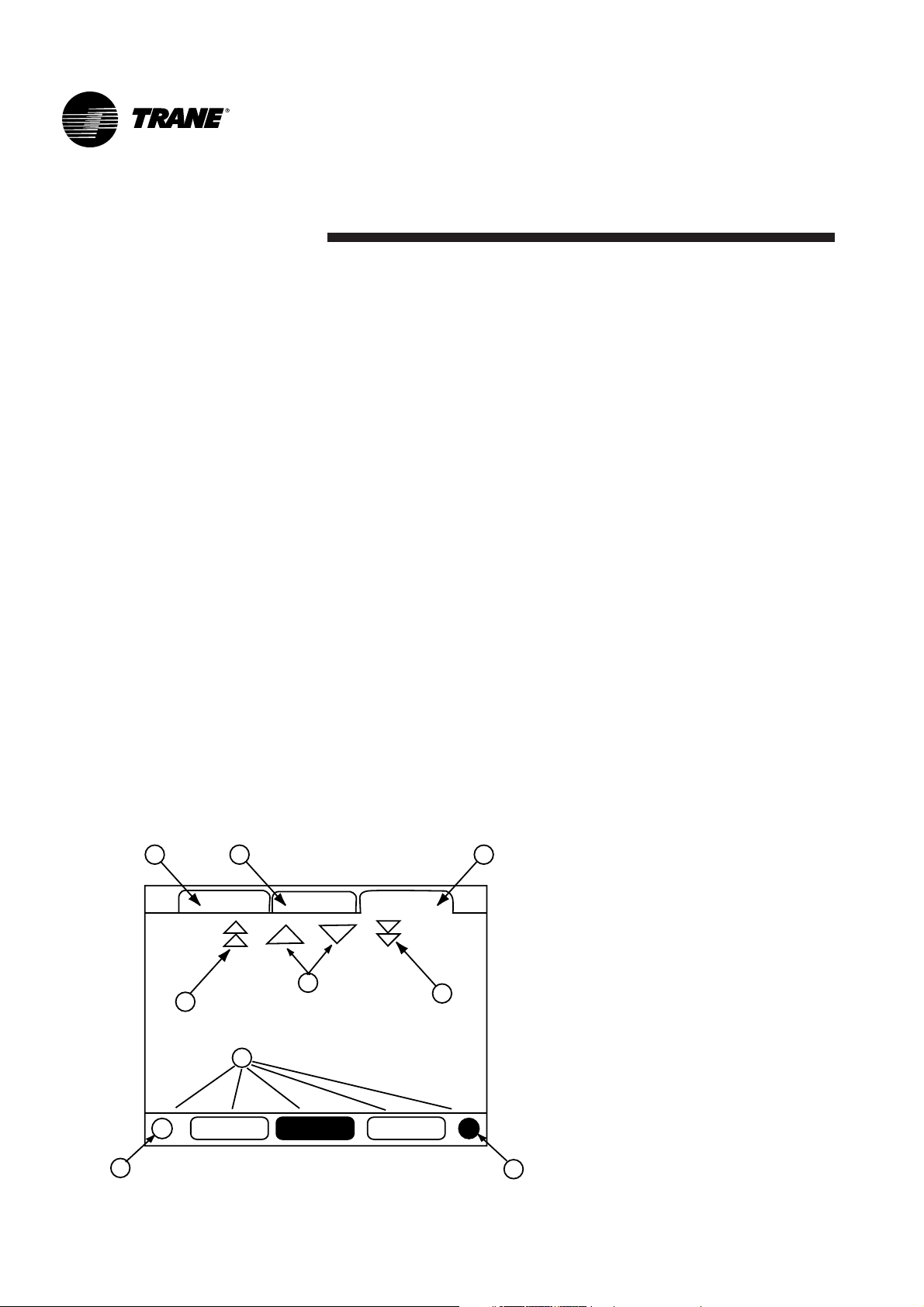
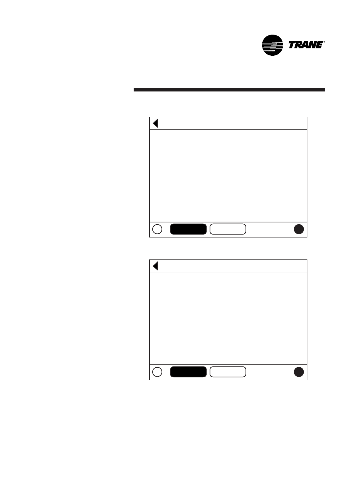
Display Screens
The main body of the screen is used
for description text, data, setpoints,
or keys (touch sensitive areas). The
Chiller Mode is displayed here.
A double arrow pointing to the right
indicates more information is
available about the specific item on
that same line. Pressing it will bring
you to a sub-screen that will present
the information or allow changes to
settings.
Figure 1 - Basic Screen Format
1 2 3
Main Reports Settings
4
5
6
7
Auto Stop Alarms
8
9
Page 7
DynaView Interface
7CG-SVU02B-E4
The bottom of the screen (7) is
present in all screens and contains
the following functions. The contrast
(8,9) may require re-adjustment at
ambient temperatures significantly
different from those present at last
adjustment. The other functions are
critical to machine operation. The
AUTO and STOP keys are used to
enable or disable the chiller. The key
selected is in black (reverse video).
The chiller will stop when the STOP
key is touched and after completing
the Run Unload mode.
Touching the AUTO key will enable
the chiller if no diagnostic is
present. (A separate action must be
taken to clear active diagnostics.)
The AUTO and STOP keys take
precedence over the Enter and
Cancel keys. (While a setting is
being changed, AUTO and STOP
keys are recognized even if Enter or
Cancel has not been pressed.) The
ALARMS button appears only when
an alarm is present, and blinks (by
alternating between normal and
reverse video) to draw attention to a
diagnostic condition. Pressing the
ALARMS button takes you to the
corresponding tab for additional
information.
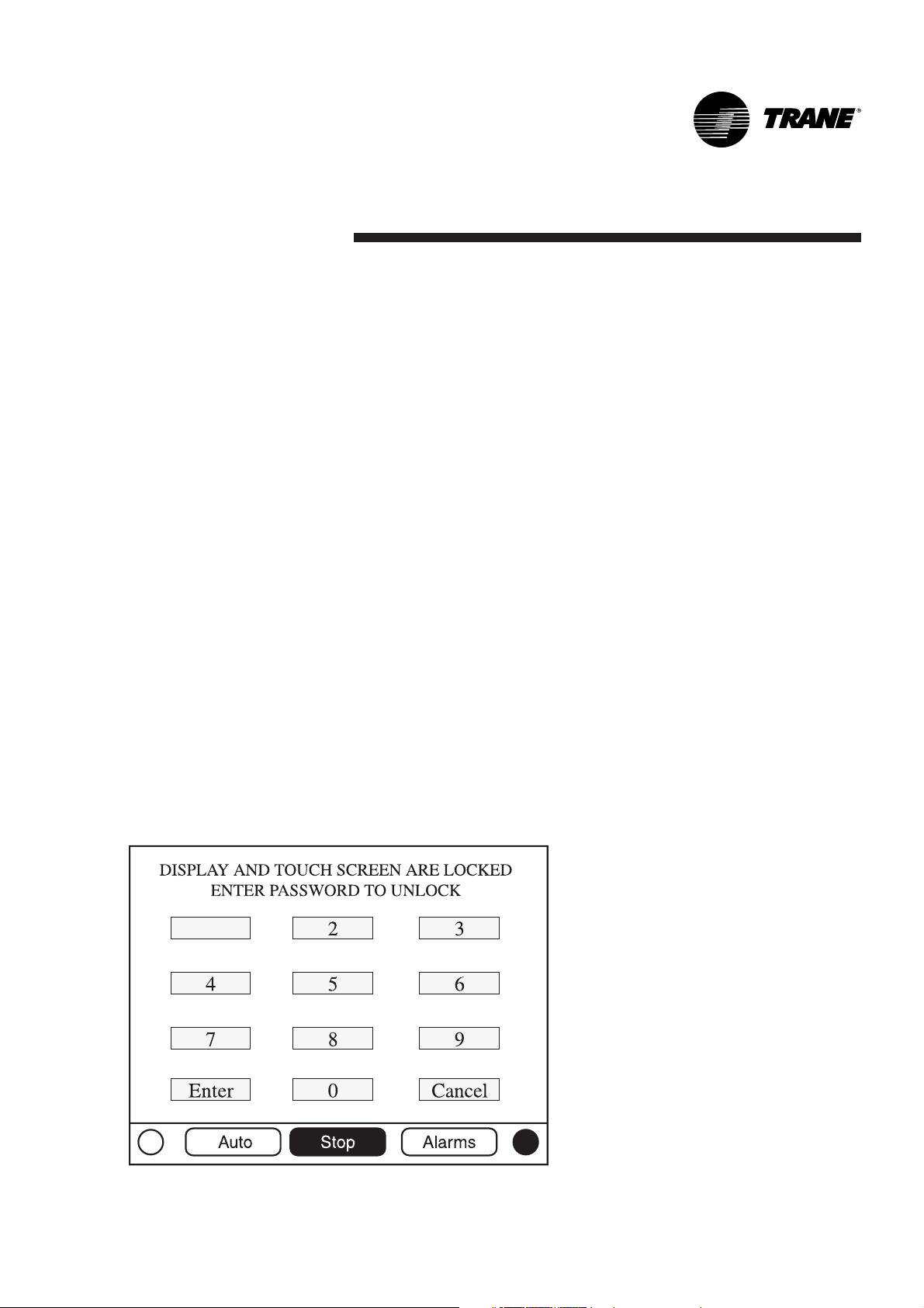
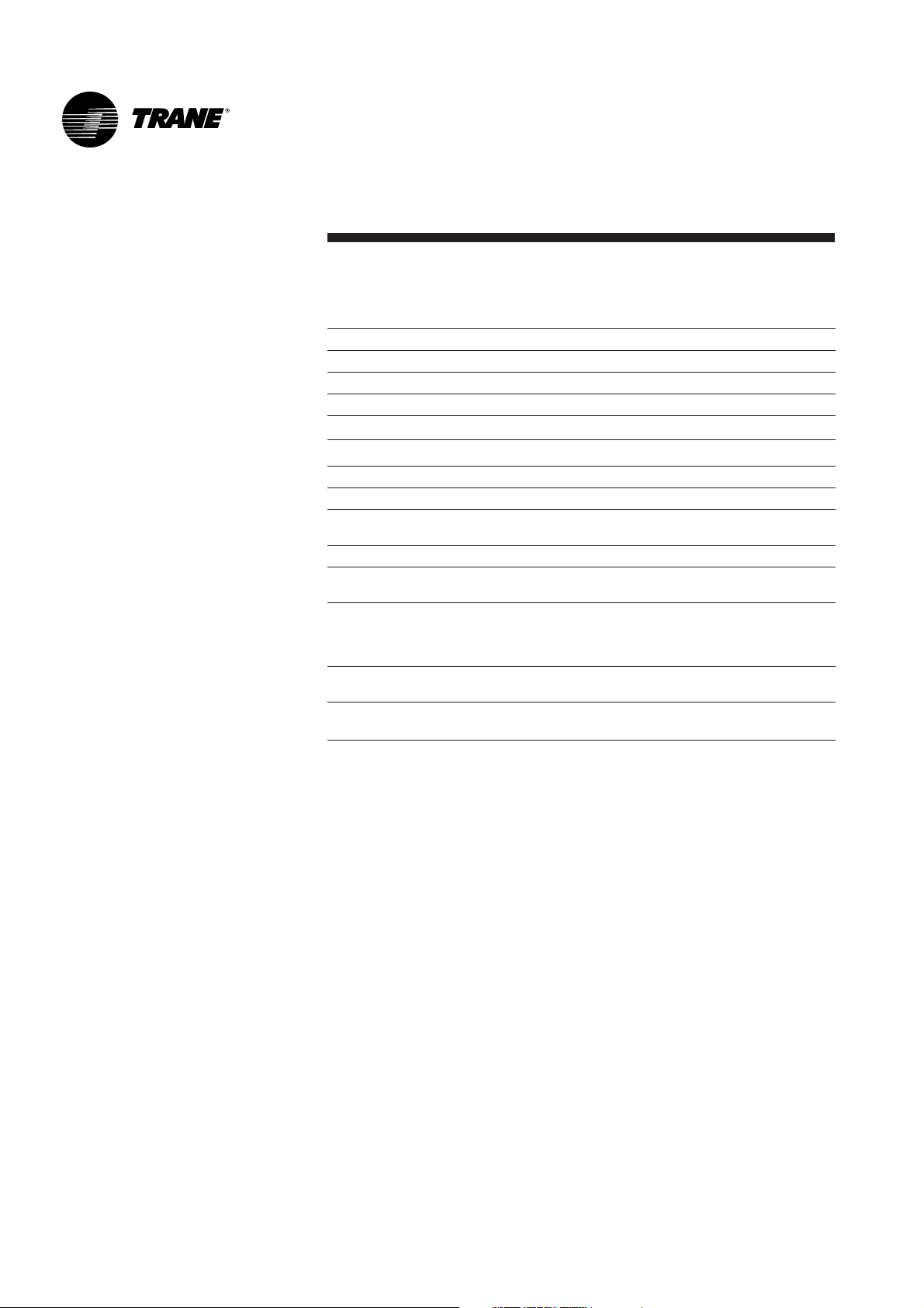
Keypad/Display Lockout
Feature
Note:
The DynaView display and
Touch Screen Lock screen is shown
above. This screen is used if the
Display and touch screen and lock
feature is enabled. Thirty minutes
after the last keystroke, this screen
is displayed and the Display and
Touch Screen is locked out until the
sequence "159 <ENTER>" is
pressed.
Until the proper password
is entered, there will be no access
to the DynaView screens including
all reports, setpoints, and
Auto/Stop/Alarms/Interlocks. The
password "159" can not be changed
from either DynaView or TechView.
For setting changes, use the
password "314 <ENTER>".
Figure 2 - Keypad
1
Page 8
DynaView Interface
CG-SVU02B-E48
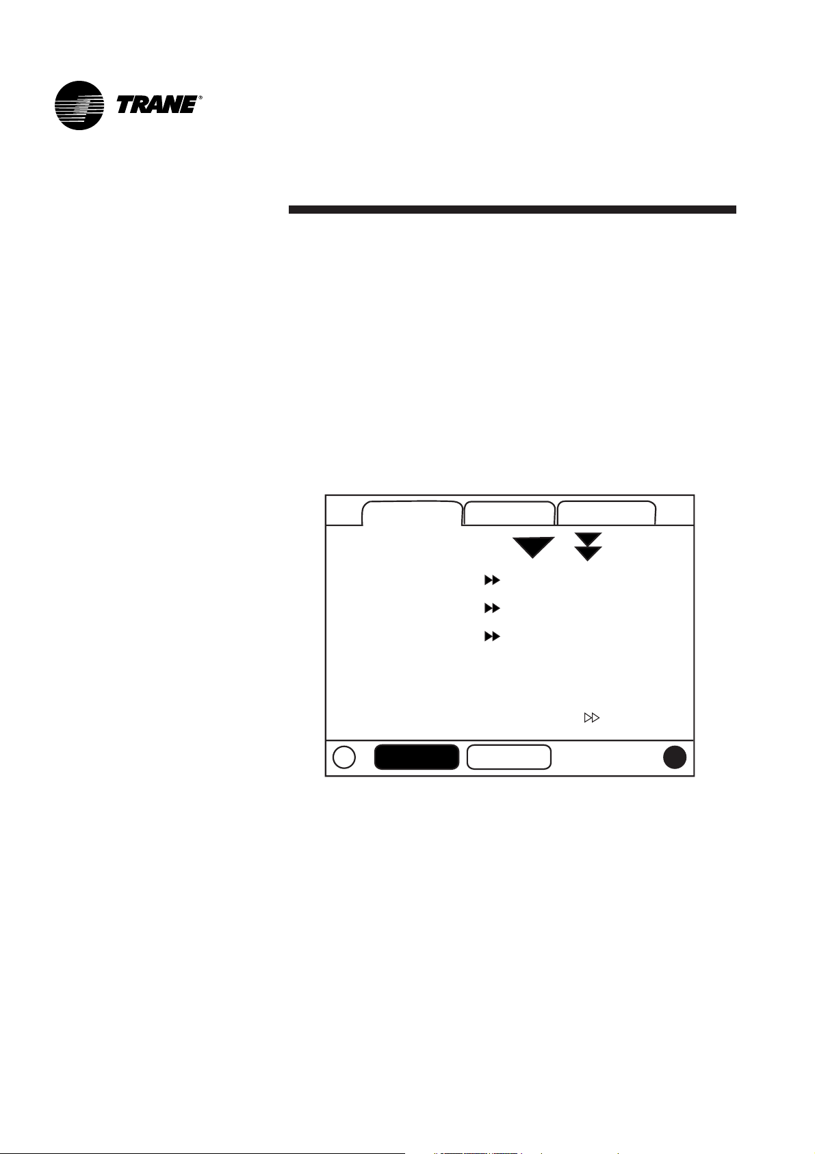
Main Screens
The Main screen shall be the default
screen. After an idle time of
30 minutes the CH530 shall display
the Main screen with the first data
fields. The remaining items (listed in
the following table) will be viewed
by selecting the up/down arrow
icons.
Figure 3 - Main screen
Main
Reports
Settings
Auto
Stop
Main
Reports
Chiller Mode:
Circuit 1 Mode:
Circuit 2 Mode:
Evap Ent / Lvg Water Temp:
Cond Ent / Lvg Water Temp:
Active Chilled Water Setpoint:
Auto
Stop
Settings
Running
Running - Limit
Auto
12 / 7 C
30 / 35 C
7 C
Page 9
DynaView Interface
9CG-SVU02B-E4
Figure 4 - Main screen menu, Chiller Operating Modes - Sub Level
Figure 5 - Main screen menu, Chiller Operating Modes - Sub Level
Auto
Stop
Auto
Stop
Back
Chiller Mode: Running
Maximum Capacity
Capacity Control Softloading
Ice Building
Auto
Back
Circuit 1 Mode: Running - Limit
Low Evaporator Pressure Start
Auto
Stop
Stop
Page 10
DynaView Interface
CG-SVU02B-E410
Table 1 - Main screen menu, Chiller Operating Modes - Top Level
Chiller Level Mode
Top Level Mode Description
MP Resetting The main processor is going through reset.
MP Resetting Sub Modes Description
No Chiller Sub-Modes
Chiller Level Mode
Top Level Mode Description
Stopped The chiller is not running either circuit, and cannot run without
intervention.
Stopped Sub Modes Description
Local Stop Chiller is stopped by the DynaView Stop button command-
cannot be remotely overridden.
Immediate Stop Chiller is stopped by the DynaView Immediate Stop (by
pressing the Stop then Immediate Stop buttons in
succession) - previous shutdown was manually commanded
to shutdown immediately.
No Circuits Available The entire chiller is stopped by circuit diagnostics or lockouts
that may automatically clear.
Diagnostic Shutdown - Manual Reset The chiller is stopped by a diagnostic that requires manual
intervention to reset.
Page 11

DynaView Interface
11CG-SVU02B-E4
Chiller Level Mode
Top Level Mode Description
Run Inhibit The chiller is currently being inhibited from starting (and
running), but may be allowed to start if the inhibiting or
diagnostic condition is cleared.
Run Inhibit Sub Modes Description
Ice Building Is Complete The chiller is inhibited from running as the Ice Building
process has been normally terminated on the evaporator
entering temperature. The chiller will not start unless the ice
building command (hardwired input or Building Automation
System command) is removed or cycled.
Start Inhibited by BAS Chiller is stopped by Tracer or other BAS system.
Start Inhibited by External Source The chiller is inhibited from starting or running by the "external
stop" hardwired input.
Diagnostic Shutdown - Auto Reset The entire chiller is stopped by a diagnostic that may
automatically clear.
Waiting for BAS Communications The chiller is inhibited because of lack of communication with
the BAS. This is only valid 15 minutes after power up.
Start Inhibited by Low Ambient Temp The chiller is inhibited based on the outdoor air temperature.
Chiller Level Mode
Top Level Mode Description
Auto The chiller is not currently running but can be expected to
start at any moment given that the proper conditions and
interlocks are satisfied.
Auto Sub Modes Description
Waiting For Evaporator Water Flow The chiller will wait a user adjustable time in this mode for
evaporator water flow to be established per the flow switch
hardwired input.
Waiting For A Need To Cool The chiller will wait indefinitely in this mode, for an evaporator
leaving water temperature higher than the Chilled Water
Setpoint plus some control dead-band.
Waiting For A Need To Heat For water cooled (CGWN), the chiller will wait indefinitely in
this mode, for a condenser leaving water temperature lower
than the Hot Water Setpoint plus some control dead-band. For
a reversible (CXAN) the chiller will wait indefinitely in this
mode, for an evaporator leaving water temperature lower than
the Hot Water Setpoint plus some control dead-band.
Power Up Delay Inhibit: MIN:SEC On Power up, the chiller will wait for the Power Up Delay
Timer to expire.
Page 12

DynaView Interface
CG-SVU02B-E412
Chiller Level Mode
Top Level Mode Description
Waiting to Start The chiller is going through the necessary steps to allow the
lead circuit to start.
Waiting to Start Sub Modes Description
Waiting For Condenser Water Flow The chiller will wait a user adjustable time in this mode for
condenser water flow to be established per the flow switch
hardwired input.
Chiller Level Mode
Top Level Mode Description
Running At least one circuit on the chiller is currently running.
Running Sub Modes Description
Maximum Capacity The chiller is operating at its maximum capacity.
Capacity Control Softloading The control is limiting the chiller loading due to capacity based
softloading setpoints.
Unit is Building Ice The chiller is Building Ice, and will terminate on the Ice
Termination Setpoint based on the Entering Evap Water
Temperature sensor.
Chiller Level Mode
Top Level Mode Description
Running - Limit At least one circuit on the chiller is currently running, but the
operation of the chiller as a whole is being actively limited by
the controls. The sub modes that apply to the Running top
modes may also be displayed along with the following limit
specific modes.
Running - Limit Sub Modes Description
Demand Limit The number of compressors allowed to operate is being
limited to less than the available number of compressors by
either the BAS system, the front panel demand limit setpoint
or the external demand limit input.
Page 13

DynaView Interface
13CG-SVU02B-E4
Chiller Level Mode
Top Level Mode Description
Shutting Down The chiller is still running but shutdown is imminent. The
chiller is going through a compressor run-unload.
Shutting Down Sub Modes Description
The Evaporator pump is executing the pump off delay timer.
The Condenser pump is executing the pump off delay timer.
Chiller Level Mode
Top Level Mode Description
Misc. These sub modes may be displayed in most of the top level
chiller modes
Misc. Sub Modes Description
Cond Fans Inhibited By Low Pressure The condenser fans are being inhibited from running because
the ambient temperature was below 10°C and the suction
pressure status is not good at startup for each circuit.
Hot Water Control For water cooled (CGWN) the chiller is controlling to the
leaving condenser water temperature. For a reversible (CXAN)
the reversing valve is in the heating position. This sub-mode is
mutually exclusive with the Chilled Water Control mode.
Chilled Water Control For water cooled (CGWN) the chiller is controlling to the
leaving evaporator water temperature. For a reversible (CXAN)
the reversing valve is in the cooling position. This sub-mode is
mutually exclusive with the Hot Water Control mode
Manual Evaporator Pump Override The evaporator water pump relay is on due to a manual
command.
Diagnostic Evap Pump Override The evaporator water pump relay is on due to a diagnostic.
Diagnostic Condenser Fan Override The condenser fan relays are on due to a diagnostic.
Manual Condenser Pump Override The condenser water pump relay is on due to a manual
command.
Manual Compressor Control Signal Chiller capacity control is being controlled by DynaView or
Te ch Vi e w.
Anti-Freeze Heater On The anti-freeze heater is on.
Evaporator Water Pump Off Delay:
MIN:SEC
Condenser Water Pump Off Delay:
MIN:SEC
Page 14

DynaView Interface
CG-SVU02B-E414
Table 2 - Circuit Level Operating Modes:
Circuit Level Mode
Top Level Mode Description
Stopped The circuit is not running, and cannot run without
intervention.
Stopped Sub Modes Description
Diagnostic Shutdown - Manual Reset The circuit has been shutdown on a latching diagnostic.
Front Panel Circuit Lockout The circuit is manually locked out by the circuit lockout setting
- the nonvolatile lockout setting is accessible through either
the DynaView or TechView.
Circuit Level Mode
Top Level Mode Description
Run Inhibit The given circuit is currently being inhibited from starting (and
running), but may be allowed to start if the inhibiting or
diagnostic condition is cleared.
Run Inhibit Sub Modes Description
Diagnostic Shutdown - Auto Reset The circuit has been shutdown on a diagnostic that may clear
automatically.
Condenser Pressure Limit The circuit is being inhibited from starting due to high
condenser pressure.
Circuit Level Mode
Top Level Mode Description
Auto The circuit is not currently running but can be expected to
start at any moment given that the proper conditions are
satisfied.
Auto Sub Modes Description
No Circuit Sub-Modes
Circuit Level Mode
Top Level Mode Description
Waiting to Start The chiller is going through the necessary steps to allow the
lead circuit to start.
Waiting to Start Sub Modes Description
No Circuit Sub-Modes
Circuit Level Mode
Top Level Mode Description
Running The compressor on the given circuit is currently running.
Running Sub Modes Description
No Circuit Sub-Modes
Page 15

DynaView Interface
15CG-SVU02B-E4
Circuit Level Mode
Top Level Mode Description
Running - Limit The compressor on the given circuit is currently running in a
limit mode.
Running - Limit Sub Modes Description
Hot Start Limit Additional stages on a given circuit are being held off based
on leaving evaporator temperature.
Condenser Pressure Limit The circuit is being inhibited from loading due to high
condenser pressure.
Low Evaporator Pressure Limit The circuit is being inhibited from loading due to low
evaporator pressure.
Circuit Level Mode
Top Level Mode Description
Preparing Shutdown The circuit is preparing to de-energize the compressor.
Preparing Shutdown Sub Modes Description
Operational Pumpdown The operational pumpdown is enabled and the circuit is
shutting down.
Circuit Level Mode
Top Level Mode Description
Shutting Down The chiller is going through the necessary steps after de-
energizing the compressor.
Shutting Down Sub Modes Description
No Circuit Sub-Modes
Circuit Level Mode
Top Level Mode Description
Misc. These sub modes may be displayed in most of the top level
circuit modes
Misc. Sub Modes Description
Defrosting The circuit is in a defrost operational mode.
Service Pumpdown The circuit is currently performing a service pumpdown.
Compressor X Running A specific compressor is running where X is A or B.
Restart Time Inhibit Cprsr X: MIN:SEC If there is accumulated Restart Inhibit Time, it must expire
before the compressor is allowed to start. X is denoted as
compressor A or B.
Page 16

DynaView Interface
CG-SVU02B-E416
Figure 6 - Reports screen
Table 3 - Reports screen
Description Units Resolution
Evaporator
Evap Entering Water Temp Temperature + or -XXX.X
Evap Leaving Water Temp Temperature + or -XXX.X
Evap Water Flow Switch Status (Flow, No Flow)
Circuit Evaporator
Evap Sat Rfgt Temp Temperature + or -XXX.X
Suction Pressure Temperature + or -XXX.X
Evap Approach Temp Temperature + or -XXX.X
Condenser
Cond Entering Water Temp Temperature + or -XXX.X
Cond Leaving Water Temp Temperature + or -XXX.X
Cond Water Flow Switch Status Enumeration (Flow, No Flow)
Outdoor Air Temperature Temperature + or -XXX.X
Circuit Condenser
Cond Sat Rfgt Temp Temperature + or -XXX.X
Discharge Pressure Temperature + or -XXX.X
Cond Approach Temp Temperature + or -XXX.X
Compressor
Chiller Running Time hr:min XXXX:XX
Circuit Compressor
Compressor Starts Integer XXXX
Compressor Running Time: hr:min XXXX:XX
Reports Screen
The Reports tab will allow a user to
select from a list of possible reports
headings.
Each report will generate a list of
status items as defined in the
following tables.
Main Reports Settings
Evaporator
Condenser
Compressor
Chiller Log
Auto Stop Alarms
Page 17

DynaView Interface
17CG-SVU02B-E4
ASHRAE Chiller Log
Current Time/Date Date / Time XX:XX mmm dd, yyyy
Chiller Mode Text
Active Chilled Water Setpoint Temperature XXX.X
Evap Entering Water Temp Temperature XXX.X
Evap Leaving Water Temp Temperature XXX.X
Evap Water Flow Switch Status Text
Cond Entering Water Temp Temperature XXX.X
Cond Leaving Water Temp Temperature XXX.X
Cond Water Flow Switch Status Text
Outdoor Air Temp Temperature XXX.X
Circuit ASHRAE Log
Circuit Mode Text
Evap Sat Rfgt Temp Temperature XXX.X
Suction Pressure Pressure X
Evap Approach Temp Temperature XXX.X
Cond Sat Rfgt Temp Temperature XXX.X
Discharge Pressure Pressure X
Cond Approach Temp Temperature XXX.X
Compressor A Starts Integer XXXX
Compressor A Running Time Hours:Minute XX:XX
Compressor B Starts Integer XXXX
Compressor B Running Time Hours:Minute XX:XX
Historic Diagnostics
Page 18

DynaView Interface
CG-SVU02B-E418
Settings Screen
The Settings screen provides a user
the ability to adjust settings justified
to support daily tasks. The layout
provides a list of sub-menus,
organized by typical subsystem.
This organization allows each
subscreen to be shorter in length
which should improve the users
navigation.
Figure 7 - Settings screen
Table 4 - Settings screen
Description Units Resolution, Default
Chiller
Front Panel Chilled Water Setpt Temperature + or - XXX.X
Low Refrigerant Temp Cutout Temperature + or - XXX.X
Front Panel Demand Limit Percent X
Front Panel Ice Build Cmd Text On/Auto
Front Panel Ice Termn Setpt Temperature XXX.X
Design Delta Temp Temperature XXX.X
Setpoint Source Text (BAS/Ext/FP, Ext/ Front Panel,
Front Panel), BAS/Ext/FP
Leaving Water Temp Cutout Temperature XX.X
Circuit Staging Option Text Bal Starts/Hrs, Circuit 1 Lead,
Circuit 2 Lead), Bal Starts/Hrs
Compressor Staging Option Text (Fixed, Bal Starts/Hrs), Fixed
Main Reports Settings
Chiller
Feature Settings
Mode Overrides
Display Settings
Auto Stop Alarms
Page 19

DynaView Interface
19CG-SVU02B-E4
Feature Settings
Chilled Water Reset Text (Constant, Outdoor, Return,
Disable), Disable
Return Reset Ratio Percent XXX
Return Start Reset Temperature XXX.X
Return Maximum Reset Temperature XXX.X
Outdoor Reset Ratio Percent XXX
Outdoor Start Reset Temperature XXX.X
Outdoor Maximum Reset Temperature XXX.X
Ext Chilled Water Setpoint Text (Enable, Disable), Disable
Ice Building Text (Enable, Disable), Disable
LCI-C Diag Encoding Text (Text, Code), Text
LCI-C Diag Language Text XX
System Manual Control Settings
Evap Water Pump Text (Auto, On), Auto
Cond Water Pump Text (Auto, On), Auto
Clear Restart Inhibit Timer Time X:XX
Capacity Control Text Auto
Circuit Manual Control Settings
Cprsr A Pumpdown Text Status: (Avail, Not Avail,
Pumpdown) Override Subscreen
command buttons: (Abort,
Pumpdown) - button is either
greyed out or not shown if not
available
Cprsr B Pumpdown Text Status: (Avail, Not Avail,
Pumpdown) Override Subscreen
command buttons: (Abort,
Pumpdown) - button is either
greyed out or not shown if not
available
Front Panel Ckt Lockout Text (Not Locked Out, Locked Out),
Not Locked Out
Display Settings
Date Format Text ("mmm dd, yyy", "dd-mmm-yyyy"),
"mmm dd, yyy
Date Text xxx
Time Format Text (12-hour, 24-hour), 12-hour
Time of Day Text 00:00
Keypad/Display Lockout Text (Enable, Disable), Disable
Display Units Text (SI, English), English
Pressure Units Text (Absolute, Gauge), Gauge
Language Text (English, ...), English
Page 20

DynaView Interface
CG-SVU02B-E420
Diagnostics Screen
The diagnostic screen is accessible
by depressing the Alarms
enunciator A scrollable list of the
last (up to 20) active diagnostics will
be presented.
Performing a Reset All Active
Diagnostics will reset all active
diagnostics regardless of type,
machine or refrigerant circuit.
Compressor diagnostics, which hold
off only one compressor, will be
treated as circuit diagnostics,
consistent with the circuit to which
they belong.
The scrollable list will be sorted by
time of occurrence. If a diagnostic
of severity = warning is present, the
"Alarms" key will be present but not
flashing. If a diagnostic of severity =
shutdown (normal or immediate) is
present, the "Alarm" key will display
that is flashing. If no diagnostics
exist, the "Alarm" key will not be
present.
The "Operating Mode At Last
Diagnostic" text above the most
recent diagnostic will display a subscreen listing the operating mode
and submodes at the time of the
last diagnostic.
Figure 8 - Diagnostics screen
Main Reports Settings
Chiller Mode:
[01] 8:32 AM Nov 16, 2001
Comm Loss: Emergency Stop
[02] 8:29 AM Nov 16, 2001
MP: Reset Has Occurred
Auto Stop Alarms
Reset Diags
Stopped
Page 21

TechView Interface
21CG-SVU02B-E4
TechView is the PC (laptop) based
tool used for servicing Tracer CH530.
Technicians that make any chiller
control modification or service any
diagnostic with Tracer CH530 must
use a laptop running the software
application "TechView." TechView is
a Trane application developed to
minimize chiller downtime and aid
the technicians' understanding of
chiller operation and service
requirements.
CAUTION:
Performing any Tracer
CH530 service functions should be
done only by a properly trained
service technician. Please contact
your local Trane service agency for
assistance with any service
requirements.
TechView software is
available via Trane.com.
(http://www.trane.com/commercial/s
oftware/tracerch530/) This download
site provides a user the TechView
installation software and CH530
main processor software that must
be loaded onto your PC in order to
service a CH530 main processor.
The TechView service tool is used to
load software into the Tracer CH530
main processor.
Minimum PC requirements to install
and operate TechView are:
• Pentium II or higher processor
• 128Mb RAM
• 1024 x 768 resolution of display
• CD-ROM
• 56K modem
• 9-pin RS-232 serial connection
• Operating system Windows 2000
• Microsoft Office (MS Word,
MS Access, MS Excel)
• Parallel Port (25-pin) or USB Port
Note:
TechView was designed for
the proceeding listed laptop
configuration. Any variation will
have unknown results. Therefore,
support for TechView is limited to
only those operating systems that
meet the specific configuration
listed here. Only computers with a
Pentium II class processor or better
are supported; Intel Celeron, AMD,
or Cyrix processors are not
supported.
TechView is also used to perform
any CH530 service or maintenance
function.
Servicing a CH530 main processor
includes:
• Updating main processor
software
• Monitoring chiller operation
• Viewing and resetting chiller
diagnostics
• Low Level Intelligent Device
(LLID) replacement and binding
• Main processor replacement and
configuration modifications
• Setpoint modifications
• Service overrides
Page 22

TechView Interface
CG-SVU02B-E422
Software Download
Instructions for First Time TechView
Users
This information can also be found at
http://www.trane.com/commercial/s
oftware/tracerch530/.
1. Create a folder called "CH530" on
your C:\ drive. You will select and
use this folder in subsequent
steps so that downloaded files
are easy to locate.
2. Download the Java Runtime
installation utility file onto your
PC in the CH530 folder (please
note that this does not install
Java Runtime, it only downloads
the installation utility).
• Click on the latest version of
Java Runtime shown in the
TechView Download table.
• Select "Save this program to
disk" while downloading the files
(do not select "Run this program
from its current location").
3. Download the TechView
installation utility file onto your
PC in the CH530 folder (please
note that this does not install
TechView, it only downloads the
installation utility).
• Click on the latest version of
TechView shown in the TechView
Download table.
• Select "Save this program to
disk" while downloading the files
(do not select "Run this program
from its current location").
4. Remember where you
downloaded the files (the
"CH530" folder). You will need to
locate them to finish the
installation process.
5. Proceed to "Main Processor
Software Download" page and
read the instructions to
download the latest version of
main processor installation files.
Note: you will first select the chiller
type to obtain the available file
versions.
Page 23

TechView Interface
23CG-SVU02B-E4
6. Select the product family. A table
with the download link will
appear for that product family.
7. Download the main processor
software onto your PC in the
CH530 folder (please note that
this does not install the main
processor, it only downloads the
installation utility).
• To do this, click on the latest
version of the main processor.
• Select "Save this program to
disk" while downloading the files
(do not select "Run this program
from its current location").
8. Remember where you
downloaded the files (the
"CH530" folder). You will need to
locate them to finish the
installation process.
9. To complete the installation
process, locate the installation
utilities you downloaded into the
CH530 folder. If necessary, use
your PC's file manager to locate
the downloaded files.
10.Install the applications in the
following order by doubleclicking on the install program
and following the installation
prompts:
• Java Runtime Environment
(JRE_VXXX.exe)
Note: During the Java Runtime
Environment installation, you may
be prompted to "select the default
Java Runtime for the system
browsers...". Do not select any
system browsers at this step. There
should be no default browsers
selected for proper operation.
• TechView (6200-0347-VXXX.exe)
• The main processor
(6200-XXXX-XX-XX.exe).
- The main processor program will
self extract to the proper folder
within the TechView program
directory, provided the TechView
program is properly installed on
the C:\ drive.
11. Connect your PC to the CH530
main processor using a standard
9-pin male/9-pin female RS-232
cable.
12.Run the TechView software by
selecting the TechView icon
placed on your desktop during
the installation process. The
"Help...About" menu can be
viewed to confirm proper
installation of latest versions.
Page 24

Diagnostics
CG-SVU02B-E424
The following diagnostic table
contains all the diagnostics
possible. Not all data is available
unless tech view is connected.
Code: Three digit hexadecimal code
used on all past products to
uniquely identify diagnostics.
Diagnostic Name: Name of
Diagnostic and its source. Note that
this is the exact text used in the
User Interface and/or Service Tool
displays.
Severity: Defines the severity of the
above effect. Immediate means
immediate shutdown of the effected
portion, Normal means normal or
friendly shutdown of the effected
portion, Special Mode means a
special mode of operation (limp
along) is invoked, but without
shutdown, and Info means an
Informational Note or Warning is
generated.
Persistence: Defines whether or not
the diagnostic and its effects are to
be manually reset (Latched), or can
be either manually or automatically
reset (Nonlatched).
Criteria: Quantitatively defines the
criteria used in generating the
diagnostic and, if nonlatching, the
criteria for auto reset. If more
explanation is necessary a hot link
to the Functional Specification is
used.
Reset Level: Defines the lowest level
of manual diagnostic reset
command which can clear the
diagnostic. The manual diagnostic
reset levels in order of priority are:
Local and Remote. A diagnostic that
has a reset level of Local, can only
be reset by a local diagnostic reset
command, but not by the lower
priority remote Reset command
whereas a diagnostic listed as
Remote reset can be reset by either.
Page 25

Diagnostics
25CG-SVU02B-E4
Table 5 - Main Processor Diagnostics
Diagnostic Name Effects Severity Persistence
Active
Modes
[Inactive
Modes]
Criteria
Reset
Level
MP: Reset Has Occurred Chiller Warning NonLatch All The main processor has successfully come out of a reset and
built its application. A reset may have been due to a power up,
installing new software or configuration. This diagnostic is
immediately and automatically cleared and thus can only be
seen in the historic diagnostic list.
NA
Low Pressure Cutout Circuit Immediate Latch Starting and
Running
[Stop, See
criteria]
The suction refrigerant pressure (gauge) fell below the given
threshold for the refrigerant installed:
• 0.7 bar for R22 and R407c
• 0.3 bar for R134a
• 1.0 bar for R410a
Local
High Motor Temp/Overload Cprsr Immediate Latch All • The High Motor Temperature or the Compressor Overload
switch remained open for more than 35 minutes.
• Five compressor fault diagnostics have occurred within the
last 210 minutes.
Local
Compressor Fault Cprsr Immediate NonLatch All The High Motor Temperature or the Compressor Overload
switch input is open.
Local
BAS Failed to Establish
Communication
Chiller Special NonLatch At power-up The BAS was setup as "installed" and the BAS did not
communicate with the MP within 15 minutes after power-up.
Remote
BAS Communication Lost Chiller Special NonLatch All The BAS was setup as "installed" at the MP and the Comm
3 LLID lost communications with the BAS for 15 continuous
minutes after it had been established. The chiller follows the
value of the Tracer Default Run Command which can be
previously written by Tracer and stored nonvolatilely by the MP
(either use local or shutdown).
Remote
External Chilled/Hot Water
Setpoint
Chiller Warning NonLatch All a. Function Not "Enabled": no diagnostics.
b. "Enabled ": Out-Of-Range Low or Hi or bad LLID, set
diagnostic, default CWS/HWS to next level of priority (e.g.
Front Panel SetPoint). This Warning diagnostic will automatically
reset if the input returns to the normal range.
Remote
External Demand Limit
Setpoint
Chiller Warning NonLatch All a. Function Not "Enabled": no diagnostics.
b. "Enabled ": Out-Of-Range Low or Hi or bad LLID, set
diagnostic, default DLS to next level of priority (e.g. Front Panel
SetPoint). This Warning diagnostic will automatically reset if the
input returns to the normal range.
Remote
Circuit Pumpdown
Terminated
Circuit Warning Latch Operational/
Service
Pumpdown
[All Except
Operational
and Service
Pumpdown]
Going below the low pressure setting + 0.2 bar shall terminate
Service Pumpdown. This indicates that the suction pressure of
circuit 1 or 2 did not go below the low pressure setting + 0.2
bar within 1 minute from the start of Service Pumpdown.
Remote
Chilled Water Flow (Entering
Wate r Temp )
Chiller Immediate Latch Any Ckt(s)
Energized
[No Ckt(s)
Energized]
The entering evaporator water temperature fell below the
leaving evaporator water temperature by more than 1.7°C for
37°C sec while at least 1 compressor was running.
Remote
Page 26

Diagnostics
CG-SVU02B-E426
Evaporator Entering Water
Temp Sensor
Chiller Normal Latch All Bad Sensor or LLID Remote
Evaporator Leaving Water
Temp Sensor
Chiller Normal Latch All Bad Sensor or LLID Remote
Condenser Entering Water
Temp Sensor
Chiller Warning Latch All Bad Sensor or LLID Remote
Condenser Leaving Water
Temp Sensor
Chiller Warning Latch All Bad Sensor or LLID Remote
Discharge Pressure
Transducer
Circuit Normal Latch All Bad Sensor or LLID Remote
Suction Pressure Transducer Circuit Immediate Latch All Bad Sensor or LLID Remote
Suction Temperature Sensor Circuit Normal Latch All Bad Sensor or LLID Remote
Evaporator Protection Water
Temp Sensor
Circuit Normal Latch All Bad Sensor or LLID Remote
Low Evap Leaving Water
Temp: Unit Off
Chiller or
Circuit
Warning
and Special
Action
NonLatch Unit in Stop
Mode, or in
Auto Mode
and No
Ckt(s)
Energized
[Any Ckt
Energized]
a) The leaving chilled water temperature fell below the leaving
water temp cutout setting for 16.6°C- seconds while the Chiller
is in the Stop mode, or in Auto mode with no compressors
running. Energize Evap Water pump Relay until diagnostic auto
resets, then return to normal evap pump control. Automatic
reset occurs when the temp rises 1.1°C above the cutout
setting for 30 minutes. When this diagnostic is active AND
Leaving Water Temperature sensor diagnostic (loss of comm or
out of range) the Evap Water pump relay shall be de-energized.
b) If evaporator protection temperature sensors are installed,
the effect is on the appropriate circuit. Else, the effect is on the
chiller.
Remote
Low Evap Leaving Water
Temp: Unit On
Chiller or
Circuit
Immediate
and Special
Action
NonLatch Any Ckt[s]
Energized
[No Ckt(s)
Energizd]
a) The chilled water temperature fell below the cutout setpoint
for 16.6°C-seconds while a compressor was running.
Automatic reset occurs when the temperature rises 1.1°C
above the cutout setting for 2 minutes. This diagnostic shall not
de-energize the Evaporator Water Pump Output. If this
diagnostic is active the Low Evap Leaving Water Temp: Unit Off
diagnostic shall be suppressed.
b) If evaporator protection temperature sensors are installed,
the effect is on the appropriate circuit. Else, the effect is on the
chiller.
Remote
Low Refrigerant
Temperature
Circuit Immediate Latch All except
[Service
Pumpdown]
The Evaporator Saturated Refrigerant Temperature dropped
below the Low Refrigerant Temperature Cutout Setpoint for
16.6°C-seconds.
Local
Page 27

Diagnostics
27CG-SVU02B-E4
High Evaporator Water
Te m p e r a t u r e
Chiller Immediate NonLatch All The evaporator leaving water temperature is above 46°C. This
diagnostic shall clear once the evaporator leaving water
temperature falls below 43.3°C. This diagnostic protects the
rupture disk. The evaporator water pump shall not run when
this diagnostic is active.
Local
High Pressure Cutout Circuit Immediate Latch All The high pressure cutout switch was open for more than one
second.
Local
Emergency Stop Chiller Immediate Latch All Emergency Stop input is open. Local
Outdoor Air Temp Sensor Chiller Warning
and Special
Action
Latch All Bad Sensor or LLID. If configured as an air-cooled this
diagnostic shall use a minimum low refrigerant temperature
ignore time of 30 seconds.
Remote
MP: Non-Volatile Memory
Reformatted
None Warning Latch All MP has determined there was an error in a sector of the Non-
Volatile memory and it was reformatted. Check settings.
Remote
Check Clock Platform Warning Latch All The real time clock had detected loss of its oscillator at some
time in the past. Check / replace battery? This diagnostic can
be effectively cleared only by writing a new value to the chillers
time clock using the TechView or DynaViews set chiller time
functions.
Remote
MP: Could not Store Starts
and Hours
Platform Warning Latch All MP has determined there was an error with the previous
power down store. Starts and Hours may have been lost for
the last 24 hours.
Remote
MP: Non-Volatile Block Test
Error
Platform Warning Latch All MP has determined there was an error with a block in the Non-
Volatile memory. Check settings.
Starts/Hours Modified Cprsr Warning NonLatch All A counter for compressor starts or hours has been modified by
TechView. This diagnostic is immediately and automatically
cleared and thus can only be seen in the historic diagnostic
list.
NA
Page 28

Diagnostics
CG-SVU02B-E428
Evaporator Water
Flow Lost Pump 1
(or Pump 2)
Chiller Warning and
Special Action
NonLatch Evap pump
commanded on
After flow had been proven the chilled water flow input
was open for more than 4 continuous seconds. The
evaporator pump control will switch control to the
redundant pump. If redundant pump is not available,
diagnostic will clear when flow is established.
Remote
Evaporator Water
Flow Overdue
Pump 1 (or
Pump 2)
Chiller Warning and
Special Action
NonLatch Estab. Evap. Water
Flow on going from
STOP to AUTO.
Evaporator water flow was not proven within a user
adjustable time of the evaporator water pump relay being
energized. Diagnostic is reset with return of evaporator
water flow.
Remote
Fault Detected:
Evaporator Water
Pump 1 (or
Pump 2)
Chiller Warning and
Special Action
NonLatch All Detection of a pump fault will cause pump control to
switch to the redundant pump.
Remote
Condenser Water
Flow Lost Pump 1
(or Pump 2)
Chiller Warning and
Special Action
NonLatch Start and All Run
Modes
After flow had been proven the condenser water flow
input was open for more than 4 continuous seconds. This
diagnostic is automatically cleared once all circuits are deenergized.
Remote
Condenser Water
Flow Overdue
Pump 1 (or
Pump 2)
Chiller Warning and
Special Action
NonLatch Estab Cond Water
Flow
Condenser water flow was not proven within a user
adjustable time of the condenser water pump relay being
energized.
Remote
Fault Detected:
Condenser Water
Pump 1 (or
Pump 2)
Chiller Warning and
Special Action
NonLatch All Detection of a pump fault will cause pump control to
switch to the redundant pump.
Remote
Fan Fault Circuit Warning NonLatch All The fan fault input was open for more than 5 seconds. Local
High Condensing
Pressure Pump
Add
Chiller Warning Latch Running When running in parallel pump control, with one pump
on, a high condensing pressure will force add the second
pump. It will latch on to prevent pump cycling.
Remote
Page 29

Diagnostics
29CG-SVU02B-E4
Table 6 - Communication Diagnostics
Notes:
1. The following communication
loss diagnostics will not occur
unless that input or output is
required to be present by the
particular configuration and
installed options for the chiller.
2. Communication diagnostics
(with the exception of "Excessive
Loss of Comm" are named by
the Functional Name of the input
or output that is no longer being
heard from by the Main
Processor.
Many LLIDs, such as the Quad
Relay LLID, have more than one
functional output associated with
it. A comm loss with such a
multiple function board will
generate multiple diagnostics.
Refer to the Chiller's wiring
diagrams to relate the
occurrence of multiple
communication diagnostics back
to the physical llid boards that
they have been assigned to
(bound).
Diagnostic Name Effects Severity Persistence Active
Modes
[Inactive
Modes]
Criteria Reset
Level
Excessive Loss of Comm Chiller Immediate Latch All Loss of comm with 20% or more of the llids configured for the
system has been detected. This diagnostic will suppress the
callout of all subsequent comm loss diagnostics. Check power
supply(s) and power disconnects - troubleshoot LLIDS buss
using TechView
Remote
Comm Loss:
External Auto/Stop
Chiller Normal Latch All Continual loss of communication between the MP and the
Functional ID has occurred for a 35-40 second period.
Remote
Comm Loss:
Emergency Stop
Chiller Normal Latch All Continual loss of communication between the MP and the
Functional ID has occurred for a 35-40 second period.
Remote
Comm Loss:
Ext Ice Building Ctrl Input
Chiller Warning Latch All Continual loss of communication between the MP and the
Functional ID has occurred for a 35-40 second period. Chiller
shall revert to normal (non-ice building) mode regardless of last
state.
Remote
Comm Loss:
Outdoor Air Temperature
Chiller Warning Latch All Continual loss of communication between the MP and the
Functional ID has occurred for a 35-40 second period. If
configured as an air-cooled this diagnostic shall turn on all fans
and use a minimum LPC ignore time of 30 seconds.
Remote
Comm Loss:
Evap Leaving Water Temp
Chiller Normal Latch All Continual loss of communication between the MP and the
Functional ID has occurred for a 35-40 second period.
Remote
Comm Loss:
Evap Entering Water Temp
Chiller Normal Latch All Continual loss of communication between the MP and the
Functional ID has occurred for a 35-40 second period.
Remote
Comm Loss:
Condenser Leaving Water
Te mp
Chiller Warning Latch All Continual loss of communication between the MP and the
Functional ID has occurred for a 35-40 second period.
Remote
Comm Loss:
Condenser Entering Water
Te mp
Chiller Warning Latch All Continual loss of communication between the MP and the
Functional ID has occurred for a 35-40 second period.
Remote
Comm Loss:
Discharge Pressure
Transducer
Circuit Normal Latch All Continual loss of communication between the MP and the
Functional ID has occurred for a 35-40 second period.
Remote
Page 30

Diagnostics
CG-SVU02B-E430
Comm Loss:
Suction Pressure Transducer
Circuit Immediate Latch All Continual loss of communication between the MP and the
Functional ID has occurred for a 35-40 second period.
Remote
Comm Loss:
Ext Chilled/Hot Wtr Setpoint
Chiller Warning
and Special
Action
Latch All Continual loss of communication between the MP and the
Functional ID has occurred for a 35-40 second period. Chiller
shall discontinue use of the External Chilled/Hot Water
Setpoint source and revert to the next higher priority for
setpoint arbitration
Remote
Comm Loss:
External Demand Limit
Setpoint
Chiller Warning
and Special
Action
Latch All Continual loss of communication between the MP and the
Functional ID has occurred for a 35-40 second period. Chiller
shall discontinue use of the External Demand Limit Setpoint
source and revert to the next higher priority for setpoint
arbitration
Remote
Comm Loss:
Auxiliary Setpoint Command
Chiller Warning
and Special
Action
Latch All Continual loss of communication between the MP and the
Functional ID has occurred for a 35-40 second period. Chiller
shall discontinue use of the Auxiliary Setpoint and revert to the
Chilled Water Setpoint based on setpoint arbitration
Remote
Comm Loss:
High Pressure Cutout Switch
Chiller Immediate Latch All Continual loss of communication between the MP and the
Functional ID has occurred for a 35-40 second period.
Remote
Comm Loss:
Evaporator Water Flow Switch
Chiller Immediate Latch All Continual loss of communication between the MP and the
Functional ID has occurred for a 35-40 second period.
Remote
Comm Loss:
Condenser Water Flow Switch
Chiller Immediate Latch All Continual loss of communication between the MP and the
Functional ID has occurred for a 35-40 second period.
Remote
Comm Loss:
Local BAS Interface
Chiller Warning
and Special
Action
NonLatch All Continual loss of communication between the MP and the
Functional ID has occurred for a 35-40 second period. Use the
last values sent from BAS
Remote
Comm Loss:
Solenoid Valve
Circuit Normal Latch All Continual loss of communication between the MP and the
Functional ID has occurred for a 35-40 second period.
Remote
Comm Loss:
Motor Temp/Overload
Cprsr Immediate Latch All Continual loss of communication between the MP and the
Functional ID has occurred for a 35-40 second period.
Remote
Comm Loss:
Compressor Run Command
Cprsr Immediate Latch All Continual loss of communication between the MP and the
Functional ID has occurred for a 35-40 second period.
Remote
Comm Loss:
Protection Module Cprsr
Circuit Warning Latch All Continual loss of communication between the MP and the
Functional ID has occurred for a 35-40 second period.
Remote
Page 31

Diagnostics
31CG-SVU02B-E4
Comm Loss:
Condenser Fan Control Relays
Circuit Immediate Latch All Continual loss of communication between the MP and the
Functional ID has occurred for a 35-40 second period.
Remote
Comm Loss:
Fan Fault
Chiller Warning Latch All Continual loss of communication between the MP and the
Functional ID has occurred for a 35-40 second period.
Remote
Comm Loss:
Op Status Programmable
Relays
Chiller Warning Latch All Continual loss of communication between the MP and the
Functional ID has occurred for a 35-40 second period.
Remote
Comm Loss:
Anti-Freeze Heater Relay
Chiller Warning
and Special
Action
Latch All Continual loss of communication between the MP and the
Functional ID has occurred for a 35-40 second period.
Remote
Comm Loss:
Evap Protection Water Temp
Circuit Normal Latch All Continual loss of communication between the MP and the
Functional ID has occurred for a 35-40 second period.
Remote
Comm Loss:
Evaporator Water Pump 1 (or
Pump 2) Relay
Chiller Warning
and Special
Action
Latch All Continual loss of communication between the MP and the
Functional ID has occurred for a 35-40 second period. For
multi-pump systems, control switches to redundant pump.
Failure of both pump systems results in a normal shutdown.
Remote
Comm Loss:
Condenser Water Pump 1 (or
Pump 2) Relay
Chiller Warning
and Special
Action
Latch All Continual loss of communication between the MP and the
Functional ID has occurred for a 35-40 second period. For
multi-pump systems, control switches to redundant pump.
Failure of both pump systems results in a normal shutdown.
Remote
Comm Loss:
Evaporator Pump 1 (or
Pump 2) Fault Input
Chiller Warning
and Special
Action
Latch All Continual loss of communication between the MP and the
Functional ID has occurred for a 35-40 second period. For
multi-pump systems, control switches to redundant pump.
Failure of both pump systems results in a normal shutdown.
Remote
Comm Loss:
Condenser Pump 1 (or
Pump 2) Fault Input
Chiller Warning
and Special
Action
Latch All Continual loss of communication between the MP and the
Functional ID has occurred for a 35-40 second period. For
multi-pump systems, control switches to redundant pump.
Failure of both pump systems results in a normal shutdown.
Remote
Page 32

Diagnostics
CG-SVU02B-E432
Comm Loss: Suction
Temperature
Circuit Normal Latch All Continual loss of communication between the MP and the
Functional ID has occurred for a 35-40 second period.
Remote
Comm Loss: Compressor
Staging Relay
Circuit Normal Latch All Continual loss of communication between the MP and the
Functional ID has occurred for a 35-40 second period.
Remote
Comm Loss: Heat/Cool
Switch
Chiller Normal Latch All Continual loss of communication between the MP and the
Functional ID has occurred for a 35-40 second period.
Remote
Comm Loss: Condenser
Speed Signal
Chiller Normal Latch All Continual loss of communication between the MP and the
Functional ID has occurred for a 35-40 second period.
Remote
Comm Loss: Electronic
Expansion Valve
Circuit Normal Latch All Continual loss of communication between the MP and the
Functional ID has occurred for a 35-40 second period.
Remote
Table 7 - Main Processor - Boot Messages and Diagnostics
DynaView Display Message Description
Troubleshooting
Boot Software Part Numbers:
LS Flash
--> 6200-0318-XX
MS Flash
--> 6200-0319-XX
The "boot code" is the portion of the code that is resident in all MPs regardless of what application code (if any) is loaded. Its
main function is to run power up tests and provide a means for downloading application code via the MP's serial connection.
The Part numbers for the code are displayed in the lower left-hand corner of the DynaView during the early portion of the
power up sequence and during special programming and converter modes. See below.
Err2: RAM Pattern 1 Failure There were RAM errors detected in RAM Test Pattern #1. Recycle power, if the error persists, replace MP.
Err2: RAM Pattern 2 Failure There were RAM errors detected in RAM Test Pattern #2. Recycle power, if the error persists, replace MP.
Err2:
RAM Addr Test #1 Failure
There were RAM errors detected in RAM Address Test #1. Recycle power, if error persists, replace MP.
Err2:
RAM Addr Test #2 Failure
There were RAM errors detected in RAM Address Test #2. Recycle power, if the error persists, replace MP.
No Application Present
Please Load Application...
No Main Processor Application is present - There are no RAM Test Errors. Connect a TechView Service Tool to the MP's serial
port, provide chiller model number (configuration information) and download the configuration if prompted by TechView. Then
proceed to download the most recent application or specific version as recommended by Technical Service.
MP: Invalid Configuration MP has an invalid configuration based on the current software installed
MP Application Memory CRC
Error
App software inside the MP failed its own checksum test. Possible causes: application software in the MP is not complete software download to the MP was not completed successfully - or MP hardware problem. Note: User should attempt to
reprogram the MP if this diagnostic occurs.
App Present. Running
Selftest.Selftest Passed
An application has been detected in the Main Processor's nonvolatile memory and the boot code is proceeding to run a check
on its entirety. 8 seconds later, the boot code had completed and passed the (CRC) test. Temporary display of this screen is
part of the normal power up sequence.
App Present. Running
SelftestErr3: CRC Failure
An application has been detected in Main Processor's nonvolatile memory and the boot code is proceeding to run a check on
its entirety. A few seconds later, the boot code had completed but failed the (CRC) test.
Connect a TechView Service Tool to the MP's serial port, provide chiller model number (configuration information) and
download the configuration if prompted by TechView. Then proceed to download the most recent application or specific
version as recommended by Technical Service. Note that this error display may also occur during the programming process, if
the MP never had a valid application any time prior to the download. If the problem persists, replace the MP.
Page 33

Diagnostics
33CG-SVU02B-E4
A Valid Configuration is
Present
A valid configuration is present in the MP's nonvolatile memory. The configuration is a set of variables and settings that
define the physical makeup of this particular chiller. These include: number/airflow and type of fans, number/and size of
compressors, special features, characteristics, and control options. Temporary display of this screen is part of the normal
power up sequence.
Err4: UnHandled
InterruptRestart Timer:
[3 sec countdown timer]
An unhandled interrupt has occurred while running the application code. This event will normally cause a safe shutdown of
the entire chiller. Once the countdown timer reaches 0, the processor will reset, clear diagnostics, and attempt to restart the
application and allow a normal restart of chiller as appropriate. This condition might occur due to a severe electro-magnetic
transient such as a near lightening strike. Such events should be rare or isolated and if no damage results to the CH530
control system, the Chiller will experience a shutdown and restart. If this occurs more persistently it may be due to an
MP hardware problem. Try replacing the MP. If replacement of the MP proves ineffective, the problem may be a result of
extremely high radiated or conducted EMI. Contact Technical Service.If this screen occurs immediately after a software
download, attempt to reload both the configuration and the application. Failing this, contact Technical Service.
Err5: Operating System
ErrorRestart Timer:
[3 sec countdown timer]
An Operating System error has occurred while running the application code. This event will normally cause a safe shutdown
of the entire chiller. Once the countdown timer reaches 0, the processor will reset, clear diagnostics, and attempt to restart
the application and allow a normal restart of chiller as appropriate.See Err 4.
Err6: Watch Dog Timer
ErrorRestart Timer:
[3 sec countdown timer]
A Watch Dog Timer Error has occurred while running the application code. This event will normally cause a safe shutdown of
the entire chiller. Once the countdown timer reaches 0, the processor will reset, clear diagnostics, and attempt to restart the
application allowing a normal restart of chiller as appropriate.
Err7: Unknown ErrorRestart
Timer:
[3 sec countdown timer]
An unknown Error has occurred while running the application code. This event will normally cause a safe shutdown of the
entire chiller. Once the countdown timer reaches 0, the processor will reset, clear diagnostics, and attempt to restart the
application allowing a normal restart of chiller as appropriate
Err8: Held in Boot by User Key
Press
[3 sec countdown timer]
A touch was detected during boot indicating the user wanted to stay in boot mode. This mode can be used to recover from a
fatal software error in the application code. Cycle power on the MP to clear this error if it was unintentional.
Converter Mode A command was received from the Service Tool (Tech View) to stop the running application and run in the "converter mode".
In this mode the MP acts as a simple gateway and allows the TechView service computer to talk to all the LLIDS on the
IPC3 bus.
Programming Mode A command was received by the MP from the Tech View Service Tool and the MP is in the process of first erasing and then
writing the program code to its internal Flash (nonvolatile) Memory. Note that if the MP never had a prior application already
in memory, the error code "Err3"will be displayed instead of this, during the programming download process.
Design Note: In general, all failures/comm loss due to CH530 components should have a latching diagnostic and effect. All customer inputs failures (out of range, etc) are
generally nonlatching.
Page 34

Diagnostics
CG-SVU02B-E434
Programmable Relays
(Alarms and Status)
CH530 provides a flexible alarm or
chiller status indication to a remote
location through a hard wired
interface to a dry contact closure.
Four relays are available for this
function, and they are provided
(generally with a Quad Relay Output
LLID) as part of the Alarm Relay
Output Option.
The events/states that can be
assigned to the programmable
relays are listed in the following
table and through a TechView
configuration.
Event/state Description
Alarm - Latching This output is true whenever there is any active diagnostic that requires a manual reset to clear, that affects the chiller, the
circuit, or any of the compressors on a circuit. This classification does not include informational diagnostics.
Alarm - Auto reset This output is true whenever there is any active diagnostic that could automatically clear that affects the chiller, the circuit or
any of the compressors on a circuit. This classification does not include informational diagnostics. If all of the auto resetting
diagnostics were to clear, this output would return to a false condition.
Alarm This output is true whenever there is any diagnostic affecting any component, whether latching or automatically clearing. This
classification does not include informational diagnostics.
Warning This output is true whenever there is any informational diagnostic affecting any component, whether latching or automatically
clearing.
Chiller Limit Mode This output is true whenever the chiller has been running in one of the Unloading types of limit modes (Condenser,
Evaporator, Current Limit or Phase Imbalance Limit) continuously for the last 20 minutes. A given limit or overlapping of
different limits must be in effect continuously for 20 minutes prior to the output becoming true. It will become false, if no
Unload limits are present for 1 minute. The filter prevents short duration or transient repetitive limits from indicating. The
chiller is considered to be in a limit mode for the purposes of front panel display and annunciation, on if it is fully inhibiting
loading by virtue of being in either the "hold" or "forced unload" regions of the limit control, excluding the "limited loading
region". In previous designs, the "limit load" region of the limit control was included in the criteria for the limit mode call out
on the front panel and annunciation outputs.
Compressor Running The output is true whenever any compressors are started or running on the chiller and false when no compressors are either
starting or running on the chiller. This status may or may not reflect the true status of the compressor in Service Pumpdown
if such a mode exists for a particular chiller.
Maximum Capacity The output is true whenever the chiller has reached maximum capacity continuously for the Max Capacity Relay debounce
time. The output is false when the chiller does not have all its available compressors running continuously for the debounce
time.
Default setting Event/Status
Output relay 1 Compressor running
Output relay 2 Latching alarm
Output relay 3 Chiller limit mode
Output relay 4 Warnings
Table 8 - Chiller events/status descriptions
Table 9 - Default settings
Page 35

Notes
35CG-SVU02B-E4
Page 36

Literature Order Number CG-SVU02B-E4
Date 0805
New CG-SVU02A_0405
Literature Stocking Location Europe
Trane has a policy of continuous product and product data improvement and reserves the right to
change design and specifications without notice. Only qualified technicians should perform the
installation and servicing of equipment referred to in this publication.
www.trane.com
For more information, contact your local
sales office or e-mail us at comfort@trane.com
American Standard Europe BVBA
Registered Office: 1789 Chaussée de Wavre, 1160 Brussels - Belgium
 Loading...