

Trane CGAF 100 SE, CGAF 90 SE, CGAF 130 SE, CGAF 150 SE, CGAF 140 SE Installation Operation & Maintenance
...Page 1
Installation
Operation
Maintenance
CGAF / CXAF
Air-cooled Scroll Chillers and Heat Pumps
260 - 670 kW
CG-SVX039B-GB
Original instructions
Page 2

Table of Contents
General Information ............................................................................................................... 3
Unit Description ...................................................................................................................... 5
Unit Model Number ............................................................................................................... 6
Pre-Installation ........................................................................................................................ 8
General Data ......................................................................................................................... 10
Table 1 – General data CGAF 090-190 standard efficiency ...........................................................................................................................10
Table 2 – General data CGAF 080-190 high efficiency ..................................................................................................................................13
Table 3 – General data CGAF 080-190 extra efficiency .................................................................................................................................16
Table 4 – General data CGAF 090-150 standard efficiency (shell & tube) ...................................................................................................18
Table 5 – General data CXAF 080-190 standard efficiency ...........................................................................................................................21
Table 6 – General data CXAF 080-190 high efficiency ...................................................................................................................................24
Typical CGAF / CXAF Components location ...................................................................... 27
Installation Requirements ................................................................................................... 29
Evaporator Piping ................................................................................................................. 31
Installation Mechanical ........................................................................................................ 34
Schematic pump package .................................................................................................... 35
Evaporator Waterside ........................................................................................................... 37
General Electrical Recommendations ................................................................................. 40
Installer-Supplied Components ........................................................................................... 42
Operating Principles ............................................................................................................. 43
Operating Map ...................................................................................................................... 47
Total Heat Recovery (THR) Optional .................................................................................. 48
Table 7 – General data Total Heat Recovery (THR) CGAF 080-190 ................................................................................................................48
Table 9 – Refrigerant Charge (THR Option) CGAF 080-190 ...........................................................................................................................50
Partial Heat Recovery Optional .......................................................................................... 51
Table 10/11/12 – General data for Partial Heat Recovery CGAF 080-190 SE/HE/XE .....................................................................................52
Optional Free-Cooling .......................................................................................................... 53
Table 13 – General data Free Cooling Option 080-190 ..................................................................................................................................53
Controls / Tracer TD7 Operator Interface............................................................................. 60
Pre-Start Checkout ............................................................................................................... 61
Unit Start Up Procedures ..................................................................................................... 63
Periodic Maintenance ........................................................................................................... 65
Compressor Service Information ........................................................................................ 68
Condenser Coils MCHE Maintenance ................................................................................. 70
Integrated Pump Maintenance ............................................................................................ 71
BPHE Evaporator Maintenance ........................................................................................... 72
Log Check Sheet ................................................................................................................... 73
Recommended service routine frequencies ....................................................................... 74
Additional services ............................................................................................................... 75
2 © 2019 Trane
CG-SVX039B-GB
Page 3
General Information
Foreword
These instructions are given as a guide to good practice
in the installation, start-up, operation, and maintenance
by the user, of Trane CGAF - Chillers and CXAF – Heat
Pumps manufactured in France.
A separate manual is available for the use and
maintenance of the unit’s control, Tracer™ UC800. They
do not contain full service procedures necessary for the
continued successful operation of this equipment. The
services of a qualified technician should be employed
through the medium of a maintenance contract with a
reputable service company. Read this manual thoroughly
before unit start-up.
Note: All the Chiller / Heat Pump Units are assembled,
pressure tested, dehydrated, charged and tested in
accordance with factory standard before shipment.
Warnings and Cautions
Warnings and Cautions appear at appropriate sections
throughout this manual. Your personal safety and the
proper operation of this machine require that you follow
them carefully. The constructor assumes no liability
for installations or servicing performed by unqualified
personnel.
WARNING: Indicates a potentially hazardous situation
which, if not avoided, could result in death or serious
injury.
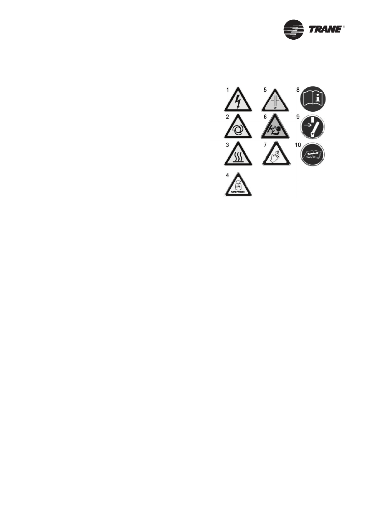
Figure 1 – Warning pictograms
1 = Risk that unit is powered up
2 = Risk hazard due to fan rotation
3 = Risk hazard of burns on compressors or refrigeration
piping
4 = Unit contains refrigerant gas. See specific warnings.
5 = Risk of residual voltage when speed drive, capacitor or
softstarter options are present
6 = Unit under pressure
7 = Risk to cut, particularly on heat exchanger fins
8 = Read instructions before installation
9 = Disconnect all electric power before servicing
10 = Read technical instructions
CAUTION: Indicates a potentially hazardous situation
which, if not avoided, may result in minor or moderate
injury. It may also be used to alert against unsafe
practices or for equipment or property-damage-only
accidents.
Safety Recommendations
To avoid death, injury, equipment or property damage,
the following recommendations should be observed
during maintenance and service visits:
1. The maximum allowable pressures for system
leak testing on low and high pressure side are
given in the chapter “Installation”. Ensure that the
pressures are within the specified limits by using
appropriate devices.
2. Disconnect all power supplies before the start of
any service activity on the unit.
3. Service work on the refrigeration system and the
electrical system should be carried out only by
qualified and experienced personnel.
4. To avoid any risk, it is recommended to place the
unit on an area with limited access.
The following pictograms can be found on the unit. Take
necessary precautions to avoid damage and injury.
Reception
On arrival,
• Inspect the unit before signing the delivery note.
• Specify any visible damage on the delivery note.
• Notify the local TRANE sales office at the same time.
Note: The delivery note must be clearly signed after
inspection and countersigned by the driver.
Also send a registered letter of protest to the last carrier
of the goods within 7 days of delivery.
Concealed damage also shall be notified by a registered
letter of protest to the last carrier of the goods within 7
days of delivery. Notify the local TRANE sales office at
the same time.
Important notice: No shipping claims will be accepted
by TRANE if the above mentioned procedure is not
respected.
For more information, refer to the general sales
conditions of your local TRANE sales office.
Note: For unit’s delivered in France, scheduled time for
unit inspection and notifying through registered letter in
case of visible and concealed damage is only 72 hours.
CG-SVX039B-GB
3
Page 4

General Information
Loose Parts Inventory
Check all the accessories and loose parts that are
shipped with the unit against the shipping list. Included
in these items will be the water vessel drain plugs,
rigging and electrical diagrams, service literature,
which are placed inside the control panel and/or starter
panel for shipment. If optional elastomeric isolators
are ordered with the unit they are shipped mounted on
the horizontal support frame of the chiller / heat pump.
The isolators’ location and distribution weight diagram
is placed with the service literature inside the starter/
control panel.
Warranty
Warranty is based on the general terms and conditions
of the manufacturer. The warranty is void if the
equipment is repaired or modified without the written
approval of the manufacturer, if the operating limits are
exceeded or if the control system or the electrical wiring
is modified. Damage due to misuse, lack of maintenance
or failure to comply with the manufacturer’s instructions
or recommendations is not covered by the warranty
obligation. If the user does not conform to the rules of
this manual, it may entail cancellation of warranty and
liabilities by the manufacturer.
Startup MUST be performed by Trane, or an authorized
agent of Trane, to VALIDATE this WARRANTY.
Training
To assist you in obtaining the best use of it and
maintaining it in perfect operating condition over a long
period of time, the manufacturer has at your disposal
a refrigeration and air conditioning service school. The
principal aim of this is to give operators and technicians
a better knowledge of the equipment they are using,
or that is under their charge. Emphasis is particularly
given to the importance of periodic checks on the
unit operating parameters as well as on preventive
maintenance, which reduces the cost of owning the unit
by avoiding serious and costly breakdown.
Refrigerant
The refrigerant provided by the manufacturer meets
all the requirements of our units. When using recycled
or reprocessed refrigerant, it is advisable to ensure its
quality is equivalent to that of a new refrigerant. For
this, it is necessary to have a precise analysis made by
a specialized laboratory. If this condition is not respected,
the manufacturer warranty could be cancelled.
Maintenance contract
It is strongly recommended that you sign a maintenance
contract with your local Service Agency.
This contract provides regular maintenance of your
installation by a specialist in our equipment. Regular
maintenance ensures that any malfunction is detected
and corrected in good time and minimizes the possibility
that serious damage will occur. Finally, regular
maintenance ensures the maximum operating life of
your equipment. We would remind you that failure to
respect these installation and maintenance instructions
may result in immediate cancellation of the warranty.
4
CG-SVX039B-GB
Page 5

Sintesis Advantage Chillers CGAF and Heat pumps
CXAF are air cooled scroll compressor units designed
for outdoor Installation. The CGAF units are cooling only
units and CXAF units are reversible and can work in
cooling and heating mode.
The units have two independent refrigerant circuits, two
or three compressors per circuit. Units are packaged
with an evaporator and condenser.
Each Unit is completely assembled, hermetic packaged,
refrigerant circuit factory piped, electrical components
wired, leak tested, dehydrated, charged and tested.
The chilled water inlet and outlet openings are covered
for shipment.
Units feature Trane’s exclusive Tracer UC800 Control
logic and controls. It monitors the control variables
that govern the operation of the unit. Control logic can
correct these variables, when necessary, to optimize
operational efficiencies, avoid unit shut down, and keep
producing chilled or hot Water.
These units comes with various options and can be
customized depending on Capacity, efficiencies, acoustic
levels, applications requirements at the time of order
placement.
Unit received and its options can be cross-checked with
the serial and model number provided in unit name
plate and description provided under unit model number
description provided in manual.
Unit Description
Nameplates
The CGAF / CXAF outdoor unit nameplates are applied
to the exterior of the control panel. A compressor
nameplate is located on each compressor.
Unit Nameplate
The unit nameplate provides the following information:
• Unit model and size description
• Unit serial number
• Identifies unit electrical requirements
• Lists correct operating charges of refrigerant and
refrigerant oil
• Lists unit test pressures
Compressor Nameplate
The compressor nameplate provides following
information:
• Compressor model number.
• Compressor serial number.
• Compressor electrical characteristics.
• Utilization range.
• Recommended refrigerant.
CG-SVX039B-GB
5
Page 6

Unit Model Number Description
Digit 1, 2, 3, 4 – Unit model
CGAF = Air-Cooled Scroll – Chiller
CXAF = Air-Cooled Scroll – Heat Pump
Digit 5-7 – Unit Nominal Tonnage
080 = 80 Tons
090 = 90 Tons
100 = 100 Tons
110 = 110 Tons
130 = 130 Tons
140 = 140 Tons
150 = 150 Tons
165 = 165 Tons
180 = 180 Tons
190 = 190 Tons
Digit 8 – Unit voltage
D = 400V/50Hz/3ph
G = 400V/50Hz/3ph Compatible with IT Neutral
Digit 9 – Manufacturing Location
E = Europe
Digit 10, 11 – Design sequence
** = Factory assigned
Digit 12 – Efficiency
N = Standard Efficiency
H = High Efficiency
A = Extra Efficiency
Digit 13 – Agency listing
C = CE Marking
Digit 14 – Pressure vessel code
2 = PED (Pressure equipment directive)
Digit 15 – Acoustic level
X = Standard noise (SN)
L = Low noise (LN)
E = Extra Low Noise (XLN)
Digit 16 – Unit Application
X = Standard Ambient [-10°C; +46°C]
L = Low Ambient [-20°C; +46°C]
H = High Ambient [-10°C; +52°C]
D = Wide Ambient [-20°C; + 52°C]
1 = Comfort application, cooling mode [10°C; 46°C] and
heating mode [-15°C; 20°C]
3 = Process application, cooling mode [-20°C; 46°C]
Heating mode [-15°C; 35°C]
Digit 17 – Relief valve option
W = Without
Digit 20 – Evaporator Configurations
B = Brazed plate heat exchanger
T = Shell & Tube heat exchanger
Digit 21 – Thermal Insulation
N = Standard
Digit 22 – Condenser Coating
N = Aluminum Micro Channel
C = E-Coated Micro Channel
B = Aluminum Fin w/o slit
E = Epoxy Coated Aluminum Fin
Digit 23 – Heat Recovery
X = No Heat Recovery
P = Partial Heat Recovery
T = Total Heat Recovery (full equipment)
Digit 24 – Hydraulic module
X = Pump signal On/Off
1 = Dual pump standard pressure
2 = Single pump standard pressure
3 = Dual pump high pressure
4 = Single pump high pressure
Digit 25 – Free Cooling
X = No Free Cooling
F = Total Free-Cooling Direct
H = Total Free-Cooling Glycol free
Digit 26 – Disconnect switch
B = With circuit breaker
Digit 27 – Under/Over Voltage
X = None
1 = Included
2 = Included with ground fault protection
Digit 28 – Human Interface language
C = Spanish
D = German
E = English
F = French
H = Dutch
I = Italian
M = Swedish
P = Polish
R = Russian
T = Czech
U = Greek
V = Portuguese
2 = Romanian
6 = Hungarian
8 = Turkish
Digit 18 – Water connection
X = Grooved pipe connection
W = Grooved pipe + welded coupling
2 = Grooved pipe with coupling and Flange adapter
Digit 19 – Evaporator Application
N = Standard cooling [4°C; 20°C]
P = Low Temperature process [-12°C; 4°C]
C = Ice Making [-7°C; 20°C] with hardwired interface
6
Digit 29 – Smart com protocol
X = None
B = BACnet interface
M = Modbus interface
L = LonTalk interface
Digit 30 – Communication customer
X = None
A = External set point & capacity outputs
CG-SVX039B-GB
Page 7

Unit Model Number Description
Digit 31 – Flow switch
X = None
F = Field installed flow switch
Digit 32 – Electrical Panel Protection
X = Enclosure with deadfront protection
1 = Enclosure with IP 20 internal protection
Digit 33 – Master Slave
X = Without
A = With
Digit 34 – Unit User Interface
L = Standard, Local UI supplied (TD7)
Digit 35 – Energy meter
X = No energy meter
M = Energy meter installed
Digit 36 – Mini Chiller Plant Control
X = No Mini PC
Digit 37 – Variable Primary Flow
X = Constant speed pump (no AFD)
A = Pump flow controlled by 3 ways Duty Valve
F = Constant Speed Pump -AFD Adjustment
T = Variable Speed Pump - Constant delta T
Digit 38 – Open for future use = X
Z = Slovenian
2 = Romanian
3 = Serbian
4 = Slovak
5 = Croatian
6 = Hungarian
8 = Turkish
Digit 44 – Shipping package
X = Standard protection
A = Containerization package
Digit 45 – Refrigerant
X = None
A = R410A Factory full Refrigerant charge
8 = R410A Factory Refrigerant Pre-Charge
Digit 46 – Isolator Valve per Manifold Compressor
X = None
Digit 47 – Power Factor Correction Capacitors
A = With
X = None
Digit 48 – Open for future use = X
Digit 49 – Freeze Protection (Factory Installed)
X = None
2 = With freeze protection
Digit 39 – Open for future use = X
Digit 40 – Power socket
X = None
P = Included (230V - 100W)
Digit 41 – Factory tests
X = No final performances test
B = Visual inspection with customer
E = Performance test without customer
Digit 42 – Installation accessory
X = None
1 = Neoprene Isolators
4 = Neoprene pads
Digit 43 – Literature language
B = Bulgarian
C = Spanish
D = German
E = English
F = French
H = Dutch
I = Italian
K = Finnish
L = Danish
M = Swedish
N = Norwegian
P = Polish
R = Russian
T = Czech
U = Greek
V = Portuguese
Digit 50 – Buffer Tank
X = No Tank
1 = With Tank
Digit 51 – Water Strainer
X = No strainer
A = Factory installed strainer
Digit 52 – Louvered panels
X = None
Digit 53 – Open for future use = X
Digit 54 – Starter type
A = Across the line starter/Direct On Line
B = Soft starter
Digit 55 – Annunciation Relay
X = None
A = With
Digit 56 – Fan type
1 = AC fan
2 = EC fan
3 = EC with Axitop
Digit 57 – Night Noise Setback (NNSB)
X = Without
1 = With NNSB
Digit 58 – Design special
X = Standard
S = Special requirement
CG-SVX039B-GB
7
Page 8

Pre-Installation
Inspection checklist
When the unit is delivered, verify that it is the correct
unit and that it is properly equipped. Compare the
information which appears on the unit nameplate with
the ordering and submittal information.
Inspect all exterior components for visible damage.
Report any apparent damage or material shortage to
the carrier and make a “unit damage” notation on the
carrier’s delivery receipt. Specify the extent and type of
damage found and notify the appropriate Trane Sales
Office. Do not proceed with installation of a damaged
unit without sales office approval.
Mandatory Start-up Checklist
This checklist is not intended to be a substitution for
the contractor’s installation instruction. This checklist is
intended to be a guide for the Trane technician just prior
to unit ‘start-up’. Many of the recommended checks and
actions could expose the technician to electrical and
mechanical hazards. Refer to the appropriate sections in
the unit manual for appropriate procedures, component
specifications and safety instructions.
Except where noted; it is implied that the technician is to
use this checklist for inspection / verification of prior task
completed by the general contractor at installation.
1. Unit clearances adequate for service and to avoid
air recirculation, etc
2. Unit exterior inspected. CGAF / CXAF condenser
coil will not be obstructed at any time by snow or
ice during winter conditions
3. Unit properly grounded
4. Crankcase heaters working for 24 hours prior to
arrival of Trane technician performing start up
5. Correct voltage supplied to unit and electric
heaters (imbalance not to exceed 2%)
6. Unit power phasing (A-B-C sequence) proper for
compressor rotation
7. Copper power wiring meets sizing requirement in
job submittal
8. All automation and remote controls installed/
wired
9. All wiring connections tight
10. Prove chilled water side Interlock and
Interconnecting
11. Wiring Interlock and externals (chilled water
pump)
12. Field installed control wiring landed on correct
terminals (external start/stop, emergency stop,
chilled water reset…)
13. Verify all refrigerant and oil valves are open/back
seated
14. Compressor oil levels (1/2 -3/4 high in glass)
proper
15. Verify chilled water strainer is clean and free of
debris and evaporator chilled water circuits are
filled
16. A pressure switch device to detect lack of water
is not included in the pump package. Installation
of this type of device is highly recommended to
avoid sealing damage due to operation of pump
without enough water
1 7. Close the fused-disconnect switches that supplies
power to the chilled water pump starter
18. Start the chilled water pump to begin circulation
of the water. Inspect piping for leaks and repair
as necessary. Check the physical presence of the
water pressure switch
19. With water circulating through the system, adjust
water flow and check water pressure drop through
evaporator
20. Return chilled water pump to auto
21. Verify all the chiller controller Menu Items
22. All panels/doors secured prior to start-up
23. All coil fins inspected and straightened
24. Rotate fans before starting unit to inspect for
potential audible and visual signs of rubbing.
Start unit
25. Press AUTO key. The unit will start if the chiller
control calls for cooling and the safety interlocks
are closed
26. Check the evaporator and the condenser
refrigerant pressure on the chiller controller
27. Confirm Superheat and sub-cooling values are
normal
28. Compressor operation normal and within
amperage rating
29. Operating log completed
30. Press stop key
31. Inspect fans again after being under load to
ensure no signs or rubbing exist
32. Verify the chilled water pump runs for at least
1 minute (possibility to configure maxi 10 mn)
after the chiller is commanded to stop (for normal
chilled water systems)
Unit storage
If the chiller is to be stored for more than one month
prior to installation, observe the following precautions:
• Store the unit in a secured area, to avoid intentional
damages.
• Close the suction, discharge and liquid-line isolation
valves.
• Store the chiller in a dry, vibration-free, secure area.
• At least every three months, attach a gauge and
manually check the pressure in the refrigerant circuit.
• If the refrigerant pressure is below 13 bar at 20°C
(or 10 bar at 10°C), call a qualified service organization
and the appropriate Trane sales office.
Note: If the unit is stored before servicing near a
construction site it is highly recommended to protect
micro channel coils from any concrete and iron element.
Failure to do so may considerably reduce reliability of
the unit.
8
CG-SVX039B-GB
Page 9
Pre-Installation
Installation requirements and contractor responsibilities
A list of the contractor responsibilities typically associated with the unit installation process is provided.
Type of requirement
Foundation • Meet foundation requirements
Rigging
Isolation
Electrical
Water piping
Insulation • Insulation • Insulation (Piping)
Water piping connection elements • Grooved pipe
Trane-supplied
Trane-installed
• Disconnect
Switch
• Unit mounted
starter
• Flow Switch
• Water Strainer
(Optional)
Trane-supplied
Field-installed
• Neoprene Pads
• Isolators
(Optional)
• Grooved pipe
couplings (or)
Flanged Adopters
Field-supplied
Field-installed
• Safety chains
• Clevis connectors
• Lifting beams
• Neoprene Pads
• Isolators (Customer Supplied)
• Wiring sizes per submittals and local codes and
regulations
• Terminal lugs
• Ground connection(s)
• BAS Wiring (optional)
• Control voltage wiring
• Chilled water pump contactor and wiring
including interlock
• Option relays and wiring
• Taps for thermometers and gauges
• Thermometers
• Water ow pressure gauges
• Isolation and balancing valves in water piping
• Vents and drains
• Pressure relief valves
• Pressure switch device to detect lack of water
CG-SVX039B-GB
9
Page 10

General Data
Table 1 – General data CGAF 090-190 Standard Efficiency
CGAF CGAF CGAF CGAF CGAF CGAF CGAF CGAF CGAF
90 100 110 130 140 150 165 180 190
SE SE SE SE SE SE SE SE SE
Net Cooling Capacity (1) (kW) 318 351 391 431 473 519 558 621 661
Net Total Power input (1) (kW) 105 120 138 157 160 183 202 211 230
Unit electrical data (2) (3) (4)
Short Circuit Unit Capacity (9) (kA) 15 15 15 15 15 15 15 15 15
Power Cable Cross Section (max) mm² 1*240 1*240 1*240 1*240 2*300 2*300 2*300 2*300 2*300
Disconnect switch size (A) 400 400 500 500 630 630 630 800 800
Digit 56=1
Maximum Power input (kW) 142.6 162.2 176.0 189.9 221.9 241.5 255.4 272.1 286.0
Max. amps (A) 237.8 270.0 292.1 314.2 368.9 401.1 423.2 451.2 473.3
Unit start up amps (w/o soft starter digit 54=A) (4)
Unit start up amps (with soft starter Digit 54=B) (4)
Displacement power factor (dpf) 0.87 0.87 0.87 0.87 0.87 0.87 0.87 0.87 0.87
Digit 56=2 or Digit 56=3
Maximum Power input (kW) 145.7 165.2 179.1 193.0 226.0 245.6 259.5 277.2 291.1
Max. amps (A) 238.4 270.6 292.7 314.8 369.7 401.9 424.0 452.2 474.3
Unit start up amps (w/o soft starter Digit 54=A) (4)
Unit start up amps (with soft starter Digit 54=B) (4)
Displacement power factor (dpf) 0.88 0.88 0.88 0.88 0.88 0.88 0.88 0.88 0.89
Compressor
Compressor Number per Circuit # 2 2 2 2 3 3 3 3 3
Type Scroll Scroll Scroll Scroll Scroll Scroll Scroll Scroll Scroll
Model Circuit 1 / Circuit 2
Max Comp Power input Circuit 1 / Circuit 2 kW
Rated Amps Circuit 1 / Circuit 2
(Digit 56=1) (4)
Rated Amps Circuit 1 / Circuit 2
(Digit 56=2 or Digit 56=3) (4)
Locked Rotor Amps Circuit 1 / Circuit 2 (4) (A)
Motor RPM (rpm) 2900 2900 2900 2900 2900 2900 2900 2900 2900
Oil sump heater Circuit 1 / Circuit 2 (W) 112/112 112/112 112/112 112/112 168/168 168/168 168/168 168/168 168/168
Evaporator
Quantity # 1 1 1 1 1 1 1 1 1
Type Stainless steel Copper Brazed plate Heat exchanger
Evaporator model
Evaporator Water Content volume (l) 31.0 35.7 40.4 48.6 48.6 56.7 64.9 73.1 81.3
Nominal water connection size
(Grooved coupling) - Without HYM
Nominal water connection size
(Grooved coupling) - With HYM
Hydraulic Module Components
Single pump - Standard head pressure option
Max available Head Pressure (kPa) 123 115 98 92 142 137 124 164 155
Motor Power (kW) 5.5 5.5 7.5 7.5 7.5 7.5 11.0 11.0 11.0
Rated Amps (A) 11.0 11.0 14.4 14.4 14.4 14.4 20.8 20.8 20.8
Single pump - High head pressure option
Max available Head Pressure (kPa) 251 247 234 232 249 252 245 234 226
Motor Power (kW) 11.0 11.0 11.0 11.0 15.0 15.0 15.0 15.0 15.0
Rated Amps (A) 20.8 20.8 20.8 20.8 28.0 28.0 28.0 28.0 28.0
Twin pump - Standard head pressure option
Max available Head Pressure (kPa) 123 115 98 92 142 137 124 164 155
Motor Power (kW) 5.5 5.5 7.5 7.5 7.5 7.5 11.0 11.0 11.0
Rated Amps (A) 11.0 11.0 14.4 14.4 14.4 14.4 20.8 20.8 20.8
(A) 495.1 527.3 631.4 653.5 626.3 658.5 762.5 790.4 812.6
(A) 367.1 399.3 466.2 488.3 498.3 530.5 597.3 625.2 647.4
(A) 495.7 527.9 632.0 654.1 627.1 659.3 763.3 791.4 813.6
367.7 399.9 466.8 488.9 499.1 531.3 598.1 626.2 648.4
25+30/
25+30
28.4+38.2/
28.4+38.2
35.4+46.0/
(A)
35.4+46.0
35.1+45.5/
35.1+45.5
260+320/
260+320
DFX650x106 DFX650x122 DFX650x138 DFX650x166 DFX650x166 DFX650x194 DFX650x222 DFX650x250 DFX650x278
(in) (mm)
(in) (mm)
4" -
114.3
4" -
114.3
30+30/
30+30
38.2+38.2/
38.2+38.2
47.0+47.0/
47.0+47.0
46.5+46.5/
46.5+46.5
320+320/
320+320
4" -
114.3
4" -
114.3
30+40/
30+40
38.2+45.2/
38.2+45.2
48.3+59.8/
48.3+59.8
47.7+59.0/
47.7+59.0
320+413/
320+413
4" -
114.3
4" -
114.3
40+40/
40+40
45.2+45.2/
45.2+45.2
61.7+61.7/
61.7+61.7
60.7+60.7/
60.7+60.7
413+413/
413+413
4" -
114.3
4" -
114.3
25+30+30/
25+30+30
28.4+38.2+38.2/
28.4+38.2+38.2
35.5+48.1+48.1/
35.5+48.1+48.1
35.1+47.5+47.5/
35.1+47.5+47.5
260+320+320/
260+320+320
5" -
139.7
5" -
139.7
30+30+30/
30+30+30
38.2+38.2+38.2/
38.2+38.2+38.2
48.2+48.2+48.2/
48.2+48.2+48.2
47.5+47.5+47.5/
47.5+47.5+47.5
320+320+320/
320+320+320
5" -
139.7
5" -
139.7
30+30+40/
30+30+40
38.2+38.2+45.2/
38.2+38.2+45.2
49.2+49.2+61.0/
49.2+49.2+61.0
48.5+48.5+60.1/
48.5+48.5+60.1
320+320+413/
320+320+413
5" -
139.7
5" -
139.7
30+40+40/
30+40+40
38.2+45.2+45.2/
38.2+45.2+45.2
47.6+59.0+59.0/
47.6+59.0+59.0
47.1+58.2+58.2/
47.1+58.2+58.2
320+413+413/
320+413+413
5" -
139.7
5" -
139.7
40+40+40/
40+40+40
45.2+45.2+45.2/
45.2+45.2+45.2
60.1+60.1+60.1/
60.1+60.1+60.1
59.2+59.2+59.2/
59.2+59.2+59.2
413+413+413/
413+413+413
5" -
139.7
5" -
139.7
10
CG-SVX039B-GB
Page 11
General Data
Table 1 – General data CGAF 090-190 Standard Efficiency (continued)
CGAF CGAF CGAF CGAF CGAF CGAF CGAF CGAF CGAF
90 100 110 130 140 150 165 180 190
SE SE SE SE SE SE SE SE SE
Twin pump - High head pressure option
Max available Head Pressure (kPa) 251 247 234 232 249 252 245 234 226
Motor Power (kW) 11.0 11.0 11.0 11.0 15.0 15.0 15.0 15.0 15.0
Rated Amps (A) 20.8 20.8 20.8 20.8 28.0 28.0 28.0 28.0 28.0
Expansion Tank Volume (l) 50 50 50 50 50 50 50 50 50
Max User water loop Volume for factory
mounted expansion tank (1)
Optional water Buffer tank volume (l) 607 607 607 607 777 777 777 777 777
Antifreeze Heater without pump package
and without buffer tank
Antifreeze Heater with pump package and
without buffer tank
(Single Water Pump digit 24=2 or 4 / Dual
Water Pump digit 24=1 or 3)
Antifreeze Heater with pump package and
with buffer tank
(Single Water Pump digit 24=2 or 4 / Dual
Water Pump digit 24=1 or 3)
Condenser
Type Full aluminum Micro channel heat exchanger
Quantity of coil # 6 6 6 6 8 8 8 10 10
Face area per circuit (m²) 8.88 8.88 8.88 8.88 11.84 11.84 11.84 14.80 14.80
Condenser Fan
Quantity # 6 6 6 6 8 8 8 10 10
Diameter (mm) 800
Fan / motor Type Propeller fan : Fixed speed AC motor / Variable speed EC motor
Digit 56=1
Fan / motor Type Fixed speed AC motor
Airow per fan m3/h 15859 15778 15680 15580 15686 15684 15609 15730 15670
Max Power Input per Motor Kw 1.44 1.44 1.44 1.44 1.44 1.44 1.44 1.44 1.44
Max Amps per Motor A 2.9 2.9 2.9 2.9 2.9 2.9 2.9 2.9 2.9
Motor RPM (rpm) 900 900 900 900 900 900 900 900 900
Digit 56=2 or Digit 56 =3
Fan / motor Type Variable speed EC motor
Airow per fan m3/h 17411 17331 17235 17136 17240 17239 17165 17283 17225
Max Power Input per Motor Kw 1.95 1.95 1.95 1.95 1.95 1.95 1.95 1.95 1.95
Max Amps per Motor A 3.0 3.0 3.0 3.0 3.0 3.0 3.0 3.0 3.0
Motor RPM (SN - Digit 15=X or LN Digit 15=L and Digit 56=2)
Motor RPM (XLN - Digit 15=E and
Digit 56=2)
Motor RPM (SN - Digit 15=X or LN Digit 15=L and Digit 56=3)
Motor RPM (XLN - Digit 15=E and
Digit 56=3)
Dimensions
Unit Length (mm) 3395 3395 3395 3395 4520 4520 4520 5645 5645
Unit Width (mm) 2200 2200 2200 2200 2200 2200 2200 2200 2200
Std Unit Height (mm) 2526 2526 2526 2526 2526 2526 2526 2526 2526
Axitop EC Fan Unit - (Additional height
conguration)
Pump Package Option - (Additional length
conguration)
(l) 1750 1750 1750 1750 1750 1750 1750 1750 1750
(W) 360 420 420 420 540 640 640 640 640
1000 /
(W)
1060
1880 /
(W)
1940
(rpm) 850 850 860 920 860 900 940 890 920
840 840 840 840 840 840 840 840 840
850 850 880 940 860 920 960 900 940
800 800 800 800 800 800 800 800 800
(mm) +146 +146 +146 +146 +146 +146 +146 +146 +146
(mm) +425 +425 +425 +425 +370 +370 +370 +370 +370
1060 /
1120
1940 /
2000
1060 /
1120
1940 /
2000
1060 /
1120
1940 /
2000
1240 /
1300
2690 /
2750
1340 /
1400
2790 /
2850
1340 /
1400
2790 /
2850
1340 /
1400
2790 /
2850
1340 /
1400
2790 /
2850
CG-SVX039B-GB
11
Page 12
General Data
Table 1 – General data CGAF 090-190 Standard Efficiency (continued)
CGAF CGAF CGAF CGAF CGAF CGAF CGAF CGAF CGAF
90 100 110 130 140 150 165 180 190
SE SE SE SE SE SE SE SE SE
Weights
Shipping Weight (3) (kg) 2085 2195 2260 2325 2835 3010 3075 3440 3515
Operating Weight (3) (kg) 2145 2260 2330 2400 2915 3100 3175 3550 3630
Option Additional shipping weight
Single pump - Standard head pressure (kg) 215 220 225 225 230 230 295 310 305
Single pump - High head pressure (kg) 260 265 265 260 305 305 305 320 320
Twin pump - Standard head pressure (kg) 300 305 325 320 325 325 440 450 450
Twin pump - High head pressure (kg) 385 390 385 385 460 460 465 480 475
Axitop option (kg) 60 60 60 60 80 80 80 100 100
XLN option (kg) 115 115 115 115 150 150 150 150 150
Pump VFD option (kg) 70 70 70 70 70 70 70 70 70
Partial heat recovery option
(Digit 19 = N)
Partial heat recovery option
(Digit 19 = P)
Water Buffer tank option (kg) 250 250 250 250 330 330 330 330 330
System data
Nb of refrigerant circuit # 2 2 2 2 2 2 2 2 2
Minimum cooling load % (6) % 23 25 21 25 15 17 15 14 17
Standard/Partial Heat Recovery Unit
R410A refrigerant charge
Circuit 1 / Circuit 2
Oil charge Circuit 1 / Circuit 2 (l)
POE Oil type OIL058E / OIL057E
(kg) 45.00 45.00 65.00 65.00 75.00 75.00 75.00 75.00 75.00
(kg) 45.00 45.00 45.00 45.00 75.00 75.00 75.00 75.00 75.00
(kg) 18 / 18 19 / 19
13.4 /
13.4
13.4 /
13.4
19.5 /
19.5
13.4 /
13.4
20.5 /
20.5
13.4 /
13.4
30 / 30 32 / 32 33 / 33 38 / 38 39 / 38
23.1 /
22.1
23.1 /
23.1
23.1 /
23.1
23.1 /
23.1
23.1 /
23.1
(1) Indicative performance at Evaporator water temperature : 12°C / 7°C - Condenser air temperature 35°C - for detailed performances, on a given unit,
consult Order Write Up.
(2) Under 400V/3/50Hz.
(3) Rated Condition without Pump Package.
(4) Electrical & system data are indicative and subject to change without notice. Please refer to unit nameplate data.
(5) If the power line of the unit is protected by fuses gG of the same size as the disconnect switch.
12
CG-SVX039B-GB
Page 13
General Data
Table 2 – General data CGAF 080-190 High Efficiency
CGAF CGAF CGAF CGAF CGAF CGAF CGAF CGAF CGAF CGAF
80 90 100 110 130 140 150 165 180 190
HE HE HE HE HE HE HE HE HE HE
Net Cooling Capacity (1) (kW) 293 334 371 416 459 498 548 587 641 682
Net Total Power input (1) (kW) 90 102 115 132 149 155 176 193 205 222
Unit electrical data (2) (3) (4)
Short Circuit Unit Capacity (9) (kA) 15 15 15 15 15 15 15 15 15 15
Power Cable Cross Section (max) mm² 1*240 1*240 1*240 1*240 1*240 2*240 2*300 2*300 2*300 2*300
Disconnect switch size (A) 315 400 400 500 500 630 630 630 800 800
Digit 56=1
Maximum Power input (kW) 123.0 145.5 165.0 178.9 192.8 224.8 244.4 258.3 275.0 288.9
Max. amps (A) 205.6 243.6 275.8 297.9 320.0 374.7 406.9 429.0 457.0 479.1
Unit start up amps (w/o soft starter Digit 54=A) (4)
Unit start up amps (with soft starter Digit 54=B) (4)
Displacement power factor (dpf) 0.86 0.86 0.86 0.87 0.87 0.87 0.87 0.87 0.87 0.87
Digit 56=2
Maximum Power input (kW) 126.1 149.6 169.1 183.0 196.9 229.9 249.5 263.4 281.1 295.0
Max. amps (A) 206.2 244.4 276.6 298.7 320.8 375.7 407.9 430.0 458.2 480.3
Unit start up amps (w/o soft starter Digit 54=A) (4)
Unit start up amps (with soft starter Digit 54=B) (4)
Power factor 0.88 0.88 0.88 0.88 0.89 0.88 0.88 0.88 0.89 0.89
Compressor
Compressor Number per Circuit # 2 2 2 2 2 3 3 3 3 3
Type Scroll Scroll Scroll Scroll Scroll Scroll Scroll Scroll Scroll Scroll
Model Circuit 1 / Circuit 2
Max Comp Power input Circuit 1 / Circuit 2 kW
Rated Amps Circuit 1 / Circuit 2
(Digit 56=1) (4)
Rated Amps Circuit 1 / Circuit 2
(Digit 56=2) (4)
Locked Rotor Amps Circuit 1 / Circuit 2 (4) (A)
Motor RPM (rpm) 2900 2900 2900 2900 2900 2900 2900 2900 2900 2900
Oil sump heater Circuit 1 / Circuit 2 (W) 112/112 112/112 112/112 112/112 112/112 168/168 168/168 168/168 168/168 168/168
Evaporator
Quantity # 1 1 1 1 1 1 1 1 1 1
Type Stainless steel Copper Brazed plate Heat exchanger
Evaporator model
Evaporator Water Content volume (l) 40.4 40.4 48.6 56.7 64.9 73.1 81.3 81.3 81.3 86.0
Nominal water connection size (Grooved
coupling) - Without HYM
Nominal water connection size (Grooved
coupling) - With HYM
Hydraulic Module Components
Single pump - Standard head pressure option
Max available Head Pressure (kPa) 155 136 119 103 92 146 134 122 161 149
Motor Power (kW) 5.5 5.5 5.5 7.5 7.5 7.5 7.5 11.0 11.0 11.0
Rated Amps (A) 11.0 11.0 11.0 14.4 14.4 14.4 14.4 20.8 20.8 20.8
Single pump - High head pressure option
Max available Head Pressure (kPa) 280 266 254 242 237 257 253 249 231 220
Motor Power (kW) 11.0 11.0 11.0 11.0 11.0 15.0 15.0 15.0 15.0 15.0
Rated Amps (A) 20.8 20.8 20.8 20.8 20.8 28.0 28.0 28.0 28.0 28.0
Twin pump - Standard head pressure option
Max available Head Pressure (kPa) 155 136 119 103 92 146 134 122 161 149
Motor Power (kW) 5.5 5.5 5.5 7.5 7.5 7.5 7.5 11.0 11.0 11.0
Rated Amps (A) 11.0 11.0 11.0 14.4 14.4 14.4 14.4 20.8 20.8 20.8
(A) 419.0 500.9 533.1 637.2 659.3 632.1 664.3 768.3 796.2 818.4
(A) 315.0 372.9 405.1 472.0 494.1 504.1 536.3 603.1 631.0 653.2
(A) 419.6 501.7 533.9 638.0 660.1 633.1 665.3 769.3 797.4 819.6
315.6 373.7 405.9 472.8 494.9 505.1 537.3 604.1 632.2 654.4
(A)
(in) -
(mm)
(in) -
(mm)
25+25/
25+25
28.4+28.4/
28.4+28.4
34.9+34.9/
34.9+34.9
34.6+34.6/
34.6+34.6
260+260/
260+260
DFX650
x138
4" -
114.3
4" -
114.3
25+30/
25+30
28.4+38.2/
28.4+38.2
34.1+44.3/
34.1+44.3
34.0+44.1/
34.0+44.1
260+320/
260+320
DFX650
x138
4" -
114.3
4" -
114.3
30+30/
30+30
38.2+38.2/
38.2+38.2
44.9+44.9/
44.9+44.9
44.6+44.6/
44.6+44.6
320+320/
320+320
DFX650
x166
4" -
114.3
4" -
114.3
30+40/
30+40
38.2+45.2/
38.2+45.2
45.9+56.6/
45.9+56.6
45.4+56.1/
45.4+56.1
320+413/
320+413
DFX650
x194
4" -
114.3
4" -
114.3
40+40/
40+40
45.2+45.2/
45.2+45.2
57.9+57.9/
57.9+57.9
57.3+57.3/
57.3+57.3
413+413/
413+413
DFX650
x222
4” -
114.3
4” -
114.3
25+30+30/
25+30+30
28.4+38.2+38.2/
28.4+38.2+38.2
34.4+46.2+46.2/
34.4+46.2+46.2
34.2+45.8+45.8/
34.2+45.8+45.8
260+320+320/
260+320+320
DFX650
x250
5" -
139.7
5" -
139.7
30+30+30/
30+30+30
38.2+38.2+38.2/
38.2+38.2+38.2
46.2+46.2+46.2/
46.2+46.2+46.2
45.8+45.8+45.8/
45.8+45.8+45.8
320+320+320/
320+320+320
DFX650
x278
5" -
139.7
5" -
139.7
30+30+40/
30+30+40
38.2+38.2+45.2/
38.2+38.2+45.2
47.0+47.0+58.1/
47.0+47.0+58.1
46.4+46.4+57.4/
46.4+46.4+57.4
320+320+413/
320+320/
413
DFX650
x278
5" -
139.7
5" -
139.7
30+40+40/
30+40+40
38.2+45.2+45.2/
38.2+45.2+45.2
46.1+56.9+56.9/
46.1+56.9+56.9
45.6+56.3+56.3/
45.6+56.3+56.3
320+413+413/
320+413+413
DFX650
x278
5" -
139.7
5" -
139.7
40+40+40/
40+40+40
45.2+45.2+45.2/
45.2+45.2+45.2
57.7+57.7+57.7/
57.7+57.7+57.7
57.1+57.1+57.1/
57.1+57.1+57.1
413+413+413/
413+413+413
DFX650
x294
5" -
139.7
5" -
139.7
CG-SVX039B-GB
13
Page 14
General Data
Table 2 – General data CGAF 080-190 High Efficiency (continued)
CGAF CGAF CGAF CGAF CGAF CGAF CGAF CGAF CGAF CGAF
80 90 100 110 130 140 150 165 180 190
HE HE HE HE HE HE HE HE HE HE
Twin pump - High head pressure option
Max available Head Pressure (kPa) 280 266 254 242 237 257 253 249 231 220
Motor Power (kW) 11.0 11.0 11.0 11.0 11.0 15.0 15.0 15.0 15.0 15.0
Rated Amps (A) 20.8 20.8 20.8 20.8 20.8 28.0 28.0 28.0 28.0 28.0
Expansion Tank Volume (l) 50 50 50 50 50 50 50 50 50 50
Max User water loop Volume for factory
mounted expansion tank (1)
Optional water Buffer tank volume (l) 607 607 607 607 607 777 777 777 777 777
Antifreeze Heater without pump package
and without buffer tank
Antifreeze Heater with pump package and
without buffer tank
(Single Water Pump digit 24=2 or 4 / Dual
Water Pump digit 24=1 or 3)
Antifreeze Heater with pump package and
with buffer tank
(Single Water Pump digit 24=2 or 4 / Dual
Water Pump digit 24=1 or 3)
Condenser
Type Full aluminum Micro channel heat exchanger
Quantity of coil # 6 8 8 8 8 10 10 10 12 12
Face area per circuit (m²) 8.88 11.84 11.84 11.84 11.84 14.80 14.80 14.80 17.76 17.76
Condenser Fan
Quantity # 6 8 8 8 8 10 10 10 12 12
Diameter (mm) 800
Fan / motor Type Propeller fan : Fixed speed AC motor / Variable speed EC motor
Digit 56=1
Fan / motor Type Fixed speed AC motor
Airow per fan m3/h 15925 16020 15956 15879 15803 15840 15839 15782 15858 15809
Max Power Input per Motor Kw 1.44 1.44 1.44 1.44 1.44 1.44 1.44 1.44 1.44 1.44
Max Amps per Motor A 2.9 2.9 2.9 2.9 2.9 2.9 2.9 2.9 2.9 2.9
Motor RPM (rpm) 900 900 900 900 900 900 900 900 900 900
Digit 56=2
Fan / motor Type Variable speed EC motor
Airow per fan
(SN - Digit 15=X or LN - Digit 15=L)
Airow per fan (XLN - Digit 15=E) m3/h 17360 17453 17390 17315 17240 17276 17276 17220 17294 17246
Max Power Input per Motor Kw 1.95 1.95 1.95 1.95 1.95 1.95 1.95 1.95 1.95 1.95
Max Amps per Motor A 3 3 3 3 3 3 3 3 3 3
Motor RPM (SN - Digit 15=X or LN Digit 15=L)
Motor RPM (XLN - Digit 15=E) 840 840 840 840 840 840 840 840 840 840
Dimensions
Unit Length (mm) 3395 4520 4520 4520 4520 5645 5645 5645 6770 6770
Unit Width (mm) 2200 2200 2200 2200 2200 2200 2200 2200 2200 2200
Std Unit Height (mm) 2526 2526 2526 2526 2526 2526 2526 2526 2526 2526
Axitop EC Fan Unit - (Additional height
conguration)
Pump Package Option - (Additional length
conguration)
Weights
Shipping Weight (3) (kg) 2015 2410 2540 2615 2675 3205 3385 3425 3790 3855
Operating Weight (3) (kg) 2085 2480 2615 2700 2770 3315 3500 3540 3910 3975
Option Additional shipping weight
Single pump - Standard head pressure (kg) 215 230 225 235 235 245 240 305 330 325
Single pump - High head pressure (kg) 265 275 270 270 270 320 315 315 340 340
Twin pump - Standard head pressure (kg) 305 315 315 335 335 345 340 450 475 470
Twin pump - High head pressure (kg) 385 400 395 395 395 480 475 475 500 495
XLN option (kg) 115 115 115 115 115 150 150 150 150 150
Pump VFD option (kg) 70 70 70 70 70 70 70 70 70 70
(l) 1750 1750 1750 1750 1750 1750 1750 1750 1750 1750
(W) 420 420 420 520 520 640 640 640 640 640
1060 /
(W)
1120
1940 /
(W)
2000
(rpm) 850 850 850 860 920 860 900 940 890 920
(mm) +146 +146 +146 +146 +146 +146 +146 +146 +146 +146
(mm) +425 +425 +425 +425 +425 +370 +370
1060 /
1120
1940 /
2000
1060 /
1120
1940 /
2000
1160 /
1220
2040 /
2100
1160 /
1220
2040 /
2100
1340 /
1400
2790 /
2850
1340 /
1400
2790 /
2850
1340 /
1400
2790 /
2850
+370 +370 +370
1340 /
1400
2790 /
2850
1340 /
1400
2790 /
2850
14
CG-SVX039B-GB
Page 15

General Data
Table 2 – General data CGAF 080-190 High Efficiency (continued)
CGAF CGAF CGAF CGAF CGAF CGAF CGAF CGAF CGAF CGAF
80 90 100 110 130 140 150 165 180 190
HE HE HE HE HE HE HE HE HE HE
Partial heat recovery option
(Digit 19 = N) / (Digit 19 = P)
Water Buffer tank option (kg) 250 250 250 250 250 330 330 330 330 330
System data
Nb of refrigerant circuit # 2 2 2 2 2 2 2 2 2 2
Minimum cooling load % (6) % 25 23 25 21 25 15 17 15 14 17
Standard/Partial Heat Recovery Unit
R410A refrigerant charge
Circuit 1 / Circuit 2
Oil charge Circuit 1 / Circuit 2 (l)
POE Oil type OIL058E / OIL057E
(1) Indicative performance at Evaporator water temperature: 12°C / 7°C - Condenser air temperature 35°C - for detailed performances, on a given unit, consult
Order Write Up.
(2) Under 400V/3/50Hz.
(3) Rated Condition without Pump Package.
(4) Electrical & system data are indicative and subject to change without notice. Please refer to unit nameplate data.
(5) If the power line of the unit is protected by fuses gG of the same size as the disconnect switch.
(kg)
(kg)
45.00 /
45.00
22.0 /
22.0
13.4 /
13.4
45.00 /
45.00
27.5 /
27.5
13.4 /
13.4
45.00 /
45.00
27.5 /
27.5
13.4 /
13.4
65.00 /
45.00
28.5 /
28.5
13.4 /
13.4
65.00 /
45.00
29 / 29 39 / 39 39 / 39 39 / 39 43 / 43
13.4 /
13.4
75.00 /
75.00
23.1 /
22.1
75.00 /
75.00
23.1 /
23.1
75.00 /
75.00
23.1 /
23.1
75.00 /
75.00
23.1 /
23.1
75.00 /
75.00
43.5 /
43.5
23.1 /
23.1
CG-SVX039B-GB
15
Page 16
General Data
Table 3 – General data CGAF 080-190 Extra Efficiency
CGAF CGAF CGAF CGAF CGAF CGAF CGAF CGAF CGAF CGAF
80 90 100 110 130 140 150 165 180 190
XE XE XE XE XE XE XE XE XE XE
Net Cooling Capacity (1) (kW) 295 335 373 419 464 502 553 593 647 689
Net Total Power input (1) (kW) 87 99 112 128 145 151 172 188 200 216
Unit electrical data (2) (3) (4)
Short Circuit Unit Capacity (9) (kA) 15 15 15 15 15 15 15 15 15 15
Power Cable Cross Section (max) mm21*240 1*240 1*240 1*240 1*240 2*300 2*300 2*300 2*300 2*300
Disconnect switch size (A) 315 400 400 500 500 630 630 630 800 800
Maximum Power input (kW) 126.1 149.6 169.1 183.0 196.9 229.9 249.5 263.4 281.1 295.0
Unit rated amps (A) 206.2 244.4 276.6 298.7 320.8 375.7 407.9 430.0 458.2 480.3
Unit start up amps
(w/o soft starter - Digit 54=A) (4)
Unit start up amps
(with soft starter - Digit 54=B) (4)
Displacement power factor (dpf) 0.88 0.88 0.88 0.88 0.89 0.88 0.88 0.88 0.89 0.89
Compressor
Compressor Number per Circuit # 2 2 2 2 2 3 3 3 3 3
Type Scroll Scroll Scroll Scroll Scroll Scroll Scroll Scroll Scroll Scroll
Model Circuit 1 / Circuit 2
Max Comp Power input Circuit 1 / Circuit 2 kW
Rated Amps Circuit 1 / Circuit 2 (4) (A)
Locked Rotor Amps Circuit 1 / Circuit 2 (4) (A)
Motor RPM (rpm) 2900 2900 2900 2900 2900 2900 2900 2900 2900 2900
Oil sump heater Circuit 1 / Circuit 2 (W) 112/112 112/112 112/112 112/112 112/112 168/168 168/168 168/168 168/168 168/168
Evaporator
Quantity # 1 1 1 1 1 1 1 1 1 1
Type Stainless steel Copper Brazed plate Heat exchanger
Evaporator model
Evaporator Water Content volume (l) 40.4 40.4 48.6 56.7 64.9 73.1 81.3 81.3 81.3 86.0
Nominal water connection size (Grooved
coupling) - Without HYM
Nominal water connection size (Grooved
coupling) - With HYM
Hydraulic Module Components
Single pump - Standard head pressure option
Max available Head Pressure (kPa) 155 136
Motor Power (kW) 5.5 5.5 5.5 7.5 7.5 7.5 7.5 11.0 11.0 11.0
Rated Amps (A) 11.0 11.0 11.0 14.4 14.4 14.4 14.4 20.8 20.8 20.8
Single pump - High head pressure option
Max available Head Pressure (kPa) 280 266 254 241 232 252 257 245 229 218
Motor Power (kW) 11.0 11.0 11.0 11.0 11.0 15.0 15.0 15.0 15.0 15.0
Rated Amps (A) 20.8 20.8 20.8 20.8 20.8 28.0 28.0 28.0 28.0 28.0
Twin pump - Standard head pressure option
Max available Head Pressure (kPa) 155 136 119 102 87 141 137 115 159 146
Motor Power (kW) 5.5 5.5 5.5 7.5 7.5 7.5 7.5 11.0 11.0 11.0
Rated Amps (A) 11.0 11.0 11.0 14.4 14.4 14.4 14.4 20.8 20.8 20.8
Twin pump - High head pressure option
Max available Head Pressure (kPa) 280 266 254 241 232 252 257 245 229 218
Motor Power (kW) 11.0 11.0 11.0 11.0 11.0 15.0 15.0 15.0 15.0 15.0
Rated Amps (A) 20.8 20.8 20.8 20.8 20.8 28.0 28.0 28.0 28.0 28.0
Expansion Tank Volume (l) 50 50 50 50 50 50 50 50 50 50
Max User water loop Volume for factory
mounted expansion tank (1)
Optional water Buffer tank volume (l) 607 607 607 607 607 777 777 777 777 777
Antifreeze Heater without pump package
and without buffer tank
Antifreeze Heater with pump package and
without buffer tank
(Single Water Pump digit 24=2 or 4 / Dual
Water Pump digit 24=1 or 3)
(A) 419.6 501.7 533.9 638.0 660.1 633.1 665.3 769.3 797.4 819.6
315.6 373.7 405.9 472.8 494.9 505.1 537.3 604.1 632.2 654.4
(in) -
(mm)
(in) -
(mm)
25+25/
25+25
28.4+28.4/
28.4+28.4
34.6+34.6/
34.6+34.6
260+260/
260+260
DFX650
x138
4" -
114.3
4" -
114.3
25+30/
25+30
28.4+38.2/
28.4+38.2
33.9+44.1/
33.9+44.1
260+320/
260+320
DFX650
x138
4" -
114.3
4" -
114.3
30+30/
30+30
38.2+38.2/
38.2+38.2
44.6+44.6/
44.6+44.6
320+320/
320+320
DFX650
x166
4" -
114.3
4" -
114.3
30+40/
30+40
38.2+45.2/
38.2+45.2
45.4+56.1/
45.4+56.1
320+413/
320+413
DFX650
x194
4" -
114.3
4" -
114.3
40+40/
40+40
45.2+45.2/
45.2+45.2
57.2+57.2/
57.2+57.2
413+413/
413+413
DFX650
x222
4” -
114.3
4” -
114.3
25+30+30/
25+30+30
28.4+38.2+38.2/
28.4+38.2+38.2
34.2+45.7+45.7/
34.2+45.7+45.7
260+320+320/
260+320+320
DFX650
x250
5" -
139.7
5" -
139.7
30+30+30/
30+30+30
38.2+38.2+38.2/
38.2+38.2+38.2
45.7+45.7+45.7/
45.7+45.7+45.7
320+320+320/
320+320+320
DFX650
x278
5" -
139.7
5" -
139.7
30+30+40/
30+30+40
38.2+38.2+45.2/
38.2+38.2+45.2
46.4+46.4+57.3/
46.4+46.4+57.3
320+320+413/
320+320/413
DFX650
x278
5" -
139.7
5" -
139.7
30+40+40/
30+40+40
38.2+45.2+45.2/
38.2+45.2+45.2
45.6+56.3+56.3/
45.6+56.3+56.3
320+413+413/
320+413+413
DFX650
x278
5" -
139.7
5" -
139.7
119 102 87 141 137 115 159 146
(l) 1750 1750 1750 1750 1750 1750 1750 1750 1750 1750
(W) 420 420 420 520 520 640 640 640 640 640
(W)
1060 /
1120
1060 /
1120
1060 /
1120
1160 /
1220
1160 /
1220
1340 /
1400
1340 /
1400
1340 /
1400
1340 /
1400
40+40+40/
40+40+40
45.2+45.2+45.2/
45.2+45.2+45.2
57.0+57.0+57.0/
57.0+57.0+57.0
413+413+413/
413+413+413
DFX650
x294
5" -
139.7
5" -
139.7
1340 /
1400
16
CG-SVX039B-GB
Page 17
General Data
Table 3 – General data CGAF 080-190 Extra Efficiency (continued)
CGAF CGAF CGAF CGAF CGAF CGAF CGAF CGAF CGAF CGAF
80 90 100 110 130 140 150 165 180 190
XE XE XE XE XE XE XE XE XE XE
Antifreeze Heater with pump package and
with buffer tank
(Single Water Pump digit 24=2 or 4 / Dual
Water Pump digit 24=1 or 3)
Condenser
Type Full aluminum Micro channel heat exchanger
Quantity of coil # 6 8 8 8 8 10 10 10 12 12
Face area per circuit (m²) 8.88 11.84 11.84 11.84 11.84 14.80 14.80 14.80 17.76 17.76
Condenser Fan
Quantity # 6 8 8 8 8 10 10 10 12 12
Diameter (mm) 800
Fan / motor Type Propeller fan : Variable speed EC motor
Airow per fan m3/h 17476 17569 17506 17430 17355 17392 17391 17335 17410 17362
Max Power Input per Motor Kw 1.95 1.95 1.95 1.95 1.95 1.95 1.95 1.95 1.95 1.95
Max Amps per Motor A 3 3 3 3 3 3 3 3 3 3
Motor RPM (SN - Digit 15=X or LN Digit 15=L)
Motor RPM (XLN - Digit 15=E) (rpm) 800 800 800 800 800 800 800 800 800 800
Dimensions
Unit Length (mm) 3395 4520 4520 4520 4520 5645 5645 5645 6770 6770
Unit Width (mm) 2200 2200 2200 2200 2200 2200 2200 2200 2200 2200
Std Unit Height (mm) 2526 2526 2526 2526 2526 2526 2526 2526 2526 2526
Axitop EC Fan Unit - (Additional height
conguration)
Pump Package Option - (Additional length
conguration)
Weights
Shipping Weight (3) (kg) 2075 2490 2620 2695 2755 3305 3485 3525 3910 3975
Operating Weight (3) (kg) 2145 2560 2695 2780 2850 3415 3600 3640 4030 4095
Option Additional shipping weight
Single pump - Standard head pressure (kg) 215 230 225 235 235 245 240 305 330 325
Single pump - High head pressure (kg) 265 275 270 270 270 320 315 315 340 340
Twin pump - Standard head pressure (kg) 305 315 315 335 335 345 340 450 475 470
Twin pump - High head pressure (kg) 385 400 395 395 395 480 475 475 500 495
XLN option (kg) 115 115 115 115 115 150 150 150 150 150
Pump VFD option (kg) 70 70 70 70 70 70 70 70 70 70
Partial heat recovery option
(Digit 19 = N)
Partial heat recovery option
(Digit 19 = P)
Water Buffer tank option (kg) 250 250 250 250 250 330 330 330 330 330
System data
Nb of refrigerant circuit # 2 2 2 2 2 2 2 2 2 2
Minimum cooling load % (6) % 25 23 25 21 25 15 17 15 14 17
Standard/Partial Heat Recovery Unit
R410A refrigerant charge
Circuit 1 / Circuit 2
Oil charge Circuit 1 / Circuit 2 (l)
POE Oil type OIL058E / OIL057E
1940/
(W)
2000
(rpm) 850 850 850 880 940 860 920 960 900 940
(mm) +146 +146 +146 +146 +146 +146 +146 +146 +146 +146
(mm) +425 +425 +425 +425 +425 +370 +370 +370 +370 +370
(kg) 45.00 45.00 45.00 65.00 65.00 75.00 75.00 75.00 75.00 75.00
45.00 45.00 45.00 45.00 45.00 75.00 75.00 75.00 75.00 75.00
22.0 /
(kg)
22.0
13.4 /
13.4
1940/
2000
27.4 /
27.4
13.4 /
13.4
1940/
2000
27.6 /
27.6
13.4 /
13.4
1940/
2000
28.4 /
28.4
13.4 /
13.4
2040/
2100
29.4 /
29.4
13.4 /
13.4
2040/
2100
39.0 /
39.0
23.1 /
22.1
2790/
2850
39.0 /
39.0
23.1 /
23.1
2790/
2850
39.0 /
39.0
23.1 /
23.1
2790/
2850
43.0 /
43.0
23.1 /
23.1
2790/
2850
43.5 /
43.5
23.1 /
23.1
(1) Indicative performance at Evaporator water temperature: 12°C / 7°C - Condenser air temperature 35°C - for detailed performances, on a given unit,
consult Order Write Up.
(2) Under 400V/3/50Hz.
(3) Rated Condition without Pump Package.
(4) Electrical & system data are indicative and subject to change without notice. Please refer to unit nameplate data.
(5) If the power line of the unit is protected by fuses gG of the same size as the disconnect switch.
CG-SVX039B-GB
17
Page 18
General Data
Table 4 – General data CGAF 090-150 Standard Efficiency – Shell & Tube
CGAF CGAF CGAF CGAF CGAF CGAF
90 100 110 130 140 150
SE SE SE SE SE SE
Net Cooling Capacity (1) (kW) 319 349 384 418 483 510
Net Total Power input in cooling (1) (kW) 105 120 139 159 168 184
Unit electrical data (1) (2) (3) (4)
Short Circuit Unit Capacity (9) (kA) 15 15 15 15 15 15
Power Cable Cross Section (max) mm
Disconnect switch size (A) 400 400 500 500 630 630
Digit 56=1
Maximum Power input (kW) 154.6 174.2 188.1 201.9 228.2 257.5
Unit rated amps (A) 258.8 291.0 313.1 335.2 381.0 429.3
Unit start up amps (w/o soft starter digit 54=A) (4)
Unit start up amps (with soft starter Digit 54=B) (4)
Displacement power factor (dpf) 0.87 0.87 0.87 0.87 0.87 0.87
Digit 56=2 or Digit 56=3
Maximum Power input (kW) 156.7 176.2 190.1 204.0 231.2 260.6
Max. amps (A) 259.4 291.4 313.5 335.6 381.6 430.0
Unit start up amps (w/o soft starter Digit 54=A) (4)
Unit start up amps (with soft starter Digit 54=B) (4)
Displacement power factor (dpf) 0.88 0.88 0.88 0.88 0.88 0.88
Compressor
Compressor Number per Circuit # 2 2 2 2 3 3
Type Scroll Scroll Scroll Scroll Scroll Scroll
Model Circuit 1 / Circuit 2
Max Comp Power input Circuit 1 / Circuit 2 kW
Rated Amps Circuit 1 / Circuit 2
(Digit 56=1) (4)
Rated Amps Circuit 1 / Circuit 2
(Digit 56=2 or Digit 56=3) (4)
Locked Rotor Amps Circuit 1 / Circuit 2 (4) (A)
Motor RPM (rpm) 2900 2900 2900 2900 2900 2900
Oil sump heater Circuit 1 / Circuit 2 (W) 112/112 112/112 112/112 112/112 168/168 168/168
Evaporator
Quantity # 1 1 1 1 1 1
Type Shell & Tube Heat exchanger
Evaporator model 3511 3511 3511 3511 3519 3519
Evaporator Water Content volume (l) -- -- -- -- -- --
Unit Connections
Without pump package and no strainer
Inlet / Outlet 8" / 8" 8" / 8" 8" / 8" 8" / 8" 8" / 8" 8" / 8"
Without pump package but strainer
Inlet / Outlet 4" / 8" 4" / 8" 4" / 8" 4" / 8" 5" / 8" 5" / 8"
With pump package but no balance valve
Inlet / Outlet 4" / 8" 4" / 8" 4" / 8" 4" / 8" 5" / 8" 5" / 8"
With pump package and balance valve
Inlet / Outlet 4" / 4" 4" / 4" 4" / 4" 4" / 4" 5" / 5" 5" / 5"
Hydraulic Module Components
Single pump - Standard head pressure option
Max available Head Pressure (kPa) 124 109 147 130 122 107
Motor Power (kW) 5.5 5.5 7.5 7.5 7.5 7.5
Rated Amps (A) 11 11 14.4 14.4 14.4 14.4
Single pump - High head pressure option
Max available Head Pressure (kPa) 254 242 223 205 234 224
Motor Power (kW) 11 11 11 11 15 15
Rated Amps (A) 20.8 20.8 20.8 20.8 28 28
2
1*240 1*240 1*240 1*240 2*300 2*300
(A) 516.1 548.3 652.4 674.5 638.4 686.7
(A) 388.1 420.3 487.2 509.3 510.4 558.7
(A) 516.5 548.7 652.8 674.9 639.0 687.3
388.5 420.7 487.6 509.7 511.0 559.3
(A)
25+30/
25+30
28.4+38.2/
28.4+38.2
35.4+46.0/
35.4+46.0
35.1+45.5/
35.1+45.5
260+320/
260+320
30+30/
30+30
38.2+38.2/
38.2+38.2
47.0+47.0/
47.0+47.0
46.5+46.5/
46.5+46.5
320+320/
320+320
30+40/
30+40
38.2+45.2/
38.2+45.2
48.3+59.8/
48.3+59.8
47.7+59.0/
47.7+59.0
320+413/
320+413
40+40/
40+40
45.2+45.2/
45.2+45.2
61.7+61.7/
61.7+61.7
60.7+60.7/
60.7+60.7
413+413/
413+413
25+30+30/
25+30+30
28.4+38.2+38.2/
28.4+38.2+38.2
35.5+48.1+48.1/
35.5+48.1+48.1
35.1+47.5+47.5/
35.1+47.5+47.5
260+320+320/
260+320+320
30+30+30/
30+30+30
38.2+38.2+38.2/
38.2+38.2+38.2
48.2+48.2+48.2/
48.2+48.2+48.2
47.5+47.5+47.5/
47.5+47.5+47.5
320+320+320/
320+320+320
18
CG-SVX039B-GB
Page 19
General Data
Table 4 – General data CGAF 090-150 Standard Efficiency – Shell & Tube (continued)
CGAF CGAF CGAF CGAF CGAF CGAF
90 100 110 130 140 150
SE SE SE SE SE SE
Twin pump - Standard head pressure option
Max available Head Pressure (kPa) 124 109 147 130 122 107
Motor Power (kW) 5.5 5.5 7.5 7.5 7.5 7.5
Rated Amps (A) 11 11 14.4 14.4 14.4 14.4
Twin pump - High head pressure option
Max available Head Pressure (kPa) 254 242 223 205 234 224
Motor Power (kW) 11 11 11 11 15 15
Rated Amps (A) 20.8 20.8 20.8 20.8 28 28
Expansion Tank Volume (l) 50 50 50 50 50 50
Max User water loop Volume for factory
mounted expansion tank (1)
Antifreeze Heater without pump package
Without lter option (digit 51=X) (W) 200 200 200 200 200 200
With lter option (digit 50=A) (W) 320 320 320 320 440 440
Antifreeze Heater with single pump package
With balance valve (Digit 37=A) (W) 1160 1160 1160 1160 1340 1340
Without balance valve (Digit 37=X) (W) 900 900 900 900 1020 1020
Antifreeze Heater with dual pump package
With balance valve (Digit 37=A) (W) 1220 1220 1220 1220 1140 1140
Without balance valve (Digit 37=X) (W) 960 960 960 960 1080 1080
Condenser
Type Full aluminum Micro channel heat exchanger
Quantity of coil # 6 6 6 6 8 8
Face area per circuit (m²) 8.88 8.88 8.88 8.88 11.84 11.84
Condenser Fan
Quantity # 6 6 6 6 8 8
Diameter (mm) 800
Fan / motor Type
Digit 56=1
Fan / motor Type Fixed speed AC motor
Airow per fan m3/h 15859 15778 15680 15580 15686 15684
Max Power Input per Motor Kw 1.44 1.44 1.44 1.44 1.44 1.44
Max Amps per Motor A 2.9 2.9 2.9 2.9 2.9 2.9
Motor RPM (rpm) 900 900 900 900 900 900
Digit 56=2
Fan / motor Type Variable speed EC motor
Airow per fan m3/h 17295 17215 17120 17021 17125 17124
Max Power Input per Motor Kw 1.95 1.95 1.95 1.95 1.95 1.95
Max Amps per Motor A 3.0 3.0 3.0 3.0 3.0 3.0
Motor RPM (rpm) 840 840 840 840 840 840
Digit 56 = 3
Fan / motor Type Variable speed EC motor with Axitop
Airow per fan m3/h 17411 17331 17235 17136 17240 17239
Max Power Input per Motor Kw 1.95 1.95 1.95 1.95 1.95 1.95
Max Amps per Motor A 3 3 3 3 3 3
Motor RPM (rpm) 800 840 840 840 840 840
Dimensions
Unit Length (mm) 3395 3395 3395 3395 4520 4520
Unit Width (mm) 2200 2200 2200 2200 2200 2200
Std Unit Height (mm) 2526 2526 2526 2526 2526 2526
Axitop EC Fan Unit - (Additional height
conguration)
Pump Package Option - (Additional length
conguration)
(l) 1750 1750 1750 1750 1750 1750
Propeller fan : Fixed speed AC motor / Variable speed EC motor / Variable speed EC
motor with Axitop
(mm) +146 +146 +146 +146 +146 +146
(mm) +425 +426 +427 +428 +370 +370
CG-SVX039B-GB
19
Page 20

General Data
Table 4 – General data CGAF 090-150 Standard Efficiency – Shell & Tube (continued)
CGAF CGAF CGAF CGAF CGAF CGAF
90 100 110 130 140 150
SE SE SE SE SE SE
Weights
Shipping Weight (3) (kg) 2375 2475 2525 2555 3235 3380
Operating Weight (3) (kg) 2470 2570 2620 2650 3379 3524
Standard/Partial Heat Recovery Unit
R410A refrigerant charge
Circuit 1 / Circuit 2
Oil charge Circuit 1 / Circuit 2 (l) 12.8 / 12.8 12.8 / 12.8 12.8 / 12.8 12.8 / 12.8 23.1 / 23.1 23.1 / 23.1
POE Oil type OIL058E / OIL057E
(1) Indicative performance at Evaporator water temperature: 12°C / 7°C - Condenser air temperature 35°C - for detailed performances, on a given unit,
consult Order Write Up.
(2) Under 400V/3/50Hz.
(3) Rated Condition without Pump Package.
(4) Electrical & system data are indicative and subject to change without notice. Please refer to unit nameplate data.
(5) If the power line of the unit is protected by fuses gG of the same size as the disconnect switch.
(kg) 20 / 20 20 / 20 20 / 20 20 / 20 30 / 30 30 / 30
20
CG-SVX039B-GB
Page 21
General Data
Table 5 – General data CXAF 080-190 Standard Efficiency
CXAF CXAF CXAF CXAF CXAF CXAF CXAF CXAF CXAF CXAF
080 090 100 110 130 140 150 165 180 190
SE SE SE SE SE SE SE SE SE SE
Net Cooling / Heating Capacity (1) (kW)
278 /
276
Net Total Power input (1) (kW) 87 102 117 133 151 164 179 196 209 225
Unit electrical data (2) (3) (4)
Short Circuit Unit Capacity (9) (kA) 15 15 15 15 15 15 15 15 15 15
Power Cable Cross Section (max) mm² 1*240 1*240 1*240 1*240 1*240 1*240 2*300 2*300 2*300 2*300
Disconnect switch size (A) 315 400 400 400 500 500 630 630 630 800
Digit 56=1
Maximum Power input (kW) 122 141 161 179 193 225 244 258 275 289
Max. amps (A) 154 175 201 223 252 274 300 329 347 375
Unit start up amps (w/o soft starter Digit 54=A) (4)
Unit start up amps (with soft starter Digit 54=B) (4)
(A) 419 495 528 637 659 632 664 768 796 818
(A) 315 367 400 472 494 504 536 603 631 653
Displacement power factor (dpf) 0.84 0.84 0.84 0.86 0.86 0.86 0.86 0.85 0.86 0.86
Digit 56=2 or Digit 56 =3
Maximum Power input (kW) 130 150 169 183 197 230 249 263 281 295
Unit rated amps (A) 153 173 196 223 250 272 298 326 342 369
Unit start up amps (w/o soft starter Digit 54=A) (4)
Unit start up amps (with soft starter Digit 54=B) (4)
(A) 426 502 534 638 660 633 665 769 797 820
322 374 406 473 495 505 537 604 632 654
Displacement power factor (dpf) 0.83 0.84 0.85 0.86 0.86 0.86 0.86 0.86 0.87 0.87
Compressor
Compressor Number per Circuit # 2 2 2 2 2 3 3 3 3 3
Type Scroll Scroll Scroll Scroll Scroll Scroll Scroll Scroll Scroll Scroll
(A)
25+25/
25+25
28.4+28.4/
28.4+28.4
35.4+35.4/
35.4+35.4
35.1+35.1/
35.1+35.1
260+260/
260+260
Model Circuit 1 / Circuit 2
Max Comp Power input Circuit 1 / Circuit 2 kW
Rated Amps Circuit 1 / Circuit 2
(Digit 56=1) (4)
Rated Amps Circuit 1 / Circuit 2
(Digit 56=2 or Digit 56=3) (4)
Locked Rotor Amps Circuit 1 / Circuit 2 (4) (A)
Motor RPM (rpm) 2900 2900 2900 2900 2900 2900 2900 2900 2900 2900
Oil sump heater Circuit 1 / Circuit 2 (W) 112/112 112/112 112/112 112/112 112/112 168/168 168/168 168/168 168/168 168/168
Evaporator
Quantity # 1 1 1 1 1 1 1 1 1 1
Type Stainless steel Copper Brazed plate Heat exchanger
Evaporator model
DFX650
x138
Evaporator Water Content volume (l) 40.4 40.4 48.6 56.7 64.9 73.1 81.3 81.3 81.3 86
Nominal water connection size (Grooved
coupling) - Without HYM
Nominal water connection size (Grooved
coupling) - With HYM
(in) -
(mm)
(in) -
(mm)
4" -
114.3
4" -
114.3
Hydraulic Module Components
Single pump - Standard head pressure option
Max available Head Pressure (kPa) 153 141 137 166 157 141 143 182 163 154
Motor Power (kW) 5.5 5.5 5.5 7.5 7.5 7.5 7.5 11 11 11
Rated Amps (A) 11 11 11 14.4 14.4 14.4 14.4 20.8 20.8 20.8
Single pump - High head pressure option
Max available Head Pressure (kPa) 266 254 252 242 232 252 258 249 230 221
Motor Power (kW) 11 11 11 11 11 15 15 15 15 15
Rated Amps (A) 20.8 20.8 20.8 20.8 20.8 28 28 28 28 28
Twin pump - Standard head pressure option
Max available Head Pressure (kPa) 153 141 137 166 157 141 143 182 163 154
Motor Power (kW) 5.5 5.5 5.5 7.5 7.5 7.5 7.5 11 11 11
Rated Amps (A) 11 11 11 14.4 14.4 14.4 14.4 20.8 20.8 20.8
306 /
313
25+30/
25+30
28.4+38.2/
28.4+38.2
35.4+46.0/
35.4+46.0
35.1+45.5/
35.1+45.5
260+320/
260+320
DFX650
x138
4" -
114.3
4" -
114.3
338 /
343
30+30/
30+30
38.2+38.2/
38.2+38.2
47.0+47.0/
47.0+47.0
46.5+46.5/
46.5+46.5
320+320/
320+320
DFX650
x166
4" -
114.3
4" -
114.3
384 /
389
30+40/
30+40
38.2+45.2/
38.2+45.2
48.3+59.8/
48.3+59.8
47.7+59.0/
47.7+59.0
320+413/
320+413
DFX650
x194
4" -
114.3
4" -
114.3
421 /
421
40+40/
40+40
45.2+45.2/
45.2+45.2
61.7+61.7/
61.7+61.7
60.7+60.7/
60.7+60.7
413+413/
413+413
DFX650
x222
4” -
114.3
4” -
114.3
467 /
481
25+30+30/
25+30+30
28.4+38.2+38.2/
28.4+38.2+38.2
35.5+48.1+48.1/
35.5+48.1+48.1
35.1+47.5+47.5/
35.1+47.5+47.5
260+320+320/
260+320+320
DFX650
x250
5" -
139.7
5" -
139.7
496 /
508
30+30+30/
30+30+30
38.2+38.2+38.2/
38.2+38.2+38.2
48.2+48.2+48.2/
48.2+48.2+48.2
47.5+47.5+47.5/
47.5+47.5+47.5
320+320+320/
320+320+320
DFX650
x278
5" -
139.7
5" -
139.7
527 /
538
30+30+40/
30+30+40
38.2+38.2+45.2/
38.2+38.2+45.2
49.2+49.2+61.0/
49.2+49.2+61.0
48.5+48.5+60.1/
48.5+48.5+60.1
320+320+413/
320+320/413
DFX650
x278
5" -
139.7
5" -
139.7
585 /
599
30+40+40/
30+40+40
38.2+45.2+45.2/
38.2+45.2+45.2
47.6+59.0+59.0/
47.6+59.0+59.0
47.1+58.2+58.2/
47.1+58.2+58.2
320+413+413/
320+413+413
DFX650
x278
5" -
139.7
5" -
139.7
619 /
631
40+40+40/
40+40+40
45.2+45.2+45.2/
45.2+45.2+45.2
60.1+60.1+60.1/
60.1+60.1+60.1
59.2+59.2+59.2/
59.2+59.2+59.2
413+413+413/
413+413+413
DFX650
x294
5" -
139.7
5" -
139.7
CG-SVX039B-GB
21
Page 22
General Data
Table 5 – General data CXAF 080-190 Standard Efficiency (continued)
CXAF CXAF CXAF CXAF CXAF CXAF CXAF CXAF CXAF CXAF
080 090 100 110 130 140 150 165 180 190
SE SE SE SE SE SE SE SE SE SE
Twin pump - High head pressure option
Max available Head Pressure (kPa) 266 254 252 242 232 252 258 249 230 221
Motor Power (kW) 11 11 11 11 11 15 15 15 15 15
Rated Amps (A) 20.8 20.8 20.8 20.8 20.8 28 28 28 28 28
Expansion Tank Volume (l) 50 50 50 50 50 50 50 50 50 50
Max User water loop Volume for factory
mounted expansion tank (1)
Optional water Buffer tank volume (l) 607 607 607 607 607 777 777 777 777 777
Antifreeze Heater without pump package
and without buffer tank
Antifreeze Heater with pump package and
without buffer tank
(Single Water Pump digit 24=2 or 4 / Dual
Water Pump digit 24=1 or 3)
Antifreeze Heater with pump package and
with buffer tank
(Single Water Pump digit 24=2 or 4 / Dual
Water Pump digit 24=1 or 3)
Condenser
Type Fin-tube heat exchanger
Quantity of coil # 8 8 8 8 8 10 10 10 12 12
Face area per circuit (m²) 9.3 9.3 9.3 9.29 9.29 11.61 11.61 11.61 13.93 13.93
Condenser Fan
Quantity # 8 8 8 8 8 10 10 10 12 12
Diameter (mm) 800
Digit 56=1
Fan / motor Type Fixed speed AC motor
Airow per fan m3/h
Max Power Input per Motor Kw 0.89 0.89 0.89 1.44 1.44 1.44 1.44 1.44 1.44 1.44
Max Amps per Motor A 2.22 2.22 2.22 2.9 2.9 2.9 2.9 2.9 2.9 2.9
Motor RPM (rpm) 686 686 686 900 900 900 900 900 900 900
Digit 56=2
Fan / motor Type Variable speed EC motor
Airow per fan m3/h
Max Power Input per Motor Kw 1.95 1.95 1.95 1.95 1.95 1.95 1.95 1.95 1.95 1.95
Max Amps per Motor A 3 3 3 3 3 3 3 3 3 3
Motor RPM (rpm) 700 770 820 860 890 900 900 900 960 960
Digit 56=3
Fan / motor Type Variable speed EC motor with Axitop
Airow per fan m3/h
Max Power Input per Motor Kw 1.95 1.95 1.95 1.95 1.95 1.95 1.95 1.95 1.95 1.95
Max Amps per Motor A 3 3 3 3 3 3 3 3 3 3
Motor RPM (rpm) 660 730 780 820 850 860 860 860 910 910
Dimensions
Unit Length (mm) 4520 4520 4520 4520 4520 5645 5645 5645 6770 6770
Unit Width (mm) 2200 2200 2200 2200 2200 2200 2200 2200 2200 2200
Std Unit Height (mm) 2526 2526 2526 2526 2526 2526 2526 2526 2526 2526
Axitop EC Fan Unit - (Additional height
conguration)
Pump Package Option - (Additional length
conguration)
Weights
Shipping Weight (3) (kg) 2765 2864 2999 3081 3141 3768 3944 3984 4438 4507
Operating Weight (3) (kg) 2835 2934 3078 3168 3235 3876 4060 4100 4554 4628
(l) 1750 1750 1750 1750 1750 1750 1750 1750 1750 1750
(W) 420 420 420 520 520 640 640 640 640 640
1060 /
(W)
1120
1940 /
(W)
2000
(mm) 146 146 146 146 146 146 146 146 146 146
(mm) 425 425 425 425 425
1060 /
1120
1940 /
2000
1060 /
1120
1940 /
2000
1060 /
1220
2040 /
2100
1060 /
1220
2040 /
2100
1340 /
1400
2790 /
2850
1340 /
1400
2790 /
2850
370 370 370 370 370
1340 /
1400
2790 /
2850
1340 /
1400
2790 /
2850
1340 /
1400
2790 /
2850
22
CG-SVX039B-GB
Page 23
General Data
Table 5 – General data CXAF 080-190 Standard Efficiency (continued)
CXAF CXAF CXAF CXAF CXAF CXAF CXAF CXAF CXAF CXAF
080 090 100 110 130 140 150 165 180 190
SE SE SE SE SE SE SE SE SE SE
Option Additional shipping weight
Single pump - Standard head pressure (kg) 225 225 225 235 235 245 245 310 325 325
Single pump - High head pressure (kg) 270 270 270 270 270 320 320 320 335 335
Twin pump - Standard head pressure (kg) 315 315 315 335 335 345 345 455 470 470
Twin pump - High head pressure (kg) 395 395 395 395 395 480 480 480 495 495
Axitop option (kg) 80 80 80 80 80 100 100 100 120 120
XLN option (kg) 115 115 115 115 115 150 150 150 150 150
Pump VFD option (kg) 70 70 70 70 70 70 70 70 70 70
Water Buffer tank option (kg) 250 250 250 250 250 330 330 330 330 330
System data
Nb of refrigerant circuit # 2 2 2 2 2 2 2 2 2 2
Minimum cooling load % (6) % 25 23 25 22 25 15 17 15 14 17
Standard/Partial Heat Recovery Unit
R410A refrigerant charge
Circuit 1 / Circuit 2
Oil charge Circuit 1 / Circuit 2 (l) 14 / 14 14 / 14 14 / 14
POE Oil type OIL058E / OIL057E
(1) Indicative performance at Evaporator water temperature : 12°C / 7°C - Condenser air temperature 35°C for cooling & Condenser water temperature:
40°C / 45°C - Evaporator air temperature 7°C (6°C) - for detailed performances, on a given unit, consult Order Write Up.
(2) Under 400V/3/50Hz.
(3) Rated Condition without Pump Package.
(4) Electrical & system data are indicative and subject to change without notice. Please refer to unit nameplate data.
(5) If the power line of the unit is protected by fuses gG of the same size as the disconnect switch.
(kg) 42 / 42 42 / 42 42 / 42 43 / 43 43 / 43 59 / 58 60 / 59 60 / 59 69 / 68 69 / 68
14.1 /
14.1
14.2 /
14.2
21 / 21 21 / 21
21.1 /
21.1
21.2 /
21.2
21.3 /
21.3
CG-SVX039B-GB
23
Page 24

General Data
Table 6 – General data CXAF 080-190 High Efficiency
CXAF CXAF CXAF CXAF CXAF CXAF CXAF CXAF CXAF CXAF
080 090 100 110 130 140 150 165 180 190
HE HE HE HE HE HE HE HE HE HE
Net Cooling / Heating Capacity (1) (kW)
278 /
278
Net Total Power input (1) (kW) 87 102 117 132 150 164 179 194 206 223
Unit electrical data (2) (3) (4)
Short Circuit Unit Capacity (9) (kA) 15 15 15 15 15 15 15 15 15 15
Power Cable Cross Section (max) mm21*240 1*240 1*240 1*240 1*240 1*240 2*300 2*300 2*300 2*300
Disconnect switch size (A) 315 400 400 400 500 500 630 630 630 800
Digit 56=1
Maximum Power input (kW) 122 141 161 179 193 225 244 258 275 289
Unit rated amps (A) 153 178 204 226 255 278 304 332 351 379
Unit start up amps
(w/o soft starter - Digit 54=A) (4)
Unit start up amps
(with soft starter - Digit 54=B) (4)
(A) 419 495 528 637 659 632 664 768 796 818
315 367 400 472 494 504 536 603 631 653
Displacement power factor (dpf) 0.84 0.84 0.84 0.86 0.86 0.86 0.86 0.85 0.86 0.86
Digit 56=2 or Digit 56 =3
Maximum Power input (kW) 130 150 169 183 197 230 249 263 281 295
Unit rated amps (A) 153 176 200 226 253 276 301 329 346 373
Unit start up amps
(w/o soft starter - Digit 54=A) (4)
Unit start up amps
(with soft starter - Digit 54=B) (4)
(A) 426 502 534 638 660 633 665 769 797 820
322 374 406 473 495 505 537 604 632 654
Displacement power factor (dpf) 0.83 0.84 0.85 0.86 0.86 0.86 0.86 0.86 0.87 0.87
Compressor
Compressor Number per Circuit # 2 2 2 2 2 3 3 3 3 3
Type Scroll Scroll Scroll Scroll Scroll Scroll Scroll Scroll Scroll Scroll
(A)
(A)
25+25/
28.4+28.4/ 25+30/
35.3+35.3/
35.3+35.3
35.2+35.2/
35.2+35.2
260+260/
260+260
Model Circuit 1 / Circuit 2
Max Comp Power input Circuit 1 / Circuit 2 kW
Rated Amps
Circuit 1 / Circuit 2 (Digit 56=1)(4)
Rated Amps Circuit 1 / Circuit 2
(Digit 56=2 or Digit 56=3) (4)
Locked Rotor Amps
Circuit 1 / Circuit 2 (4)
Motor RPM (rpm) 2900 2900 2900 2900 2900 2900 2900 2900 2900 2900
Oil sump heater Circuit 1 / Circuit 2 (W) 112/112 112/112 112/112 112/112 112/112 168/168 168/168 168/168 168/168 168/168
Evaporator
Quantity # 1 1 1 1 1 1 1 1 1 1
Type Stainless steel Copper Brazed plate Heat exchanger
Evaporator model
DFX650
x138
Evaporator Water Content volume (l) 40.4 40.4 48.6 56.7 64.9 73.1 81.3 81.3 81.3 86
Nominal water connection size (Grooved
coupling) - Without HYM
Nominal water connection size (Grooved
coupling) - With HYM
Maximum pressure on water side without
pump package
(in) (mm)
(in) (mm)
4" -
114.3
4" -
114.3
(BarA) 10 10 10 10 10 10 10 10 10 10
Hydraulic Module Components
Single pump - Standard head pressure option
Max available Head Pressure (kPa) 153 141 137 166 157 141 143 182 163 154
Motor Power (kW) 5.5 5.5 5.5 7.5 7.5 7.5 7.5 11 11 11
Rated Amps (A) 11 11 11 14.4 14.4 14.4 14.4 20.8 20.8 20.8
Single pump - High head pressure option
Max available Head Pressure (kPa) 266 254 252 242 232 252 258 249 230 221
Motor Power (kW) 11 11 11 11 11 15 15 15 15 15
Rated Amps (A) 20.8 20.8 20.8 20.8 20.8 28 28 28 28 28
Twin pump - Standard head pressure option
Max available Head Pressure (kPa) 153 141 137 166 157 141 143 182 163 154
Motor Power (kW) 5.5 5.5 5.5 7.5 7.5 7.5 7.5 11 11 11
Rated Amps (A) 11 11 11 14.4 14.4 14.4 14.4 20.8 20.8 20.8
307 /
315
25+30/
25+30
36.1+46.8/
36.1+46.8
35.6+46.2/
35.6+46.2
260+320/
260+320
DFX650
x138
4" -
114.3
4" -
114.3
338 /
346
30+30/
30+30
38.2+38.2/
38.2+38.2
48.0+48.0/
48.0+48.0
46.8+46.8/
46.8+46.8
320+320/
320+320
DFX650
x166
4" -
114.3
4" -
114.3
384 /
401
30+40/
30+40
38.2+45.2/
38.2+45.2
47.9+59.2/
47.9+59.2
47.8+59.1/
47.8+59.1
320+413/
320+413
DFX650
x194
4" -
114.3
4" -
114.3
421 /
436
40+40/
40+40
45.2+45.2/
45.2+45.2
60.7+60.7/
60.7+60.7
60.3+60.3/
60.3+60.3
413+413/
413+413
DFX650
x222
4” -
114.3
4” -
114.3
466 /
495
25+30+30/
25+30+30
28.4+38.2+38.2/
28.4+38.2+38.2
36.5+47.4+47.4/
36.5+47.4+47.4
36.3+47.0+47.0/
36.3+47.0+47.0
260+320+320/
260+320+320
DFX650
x250
5" -
139.7
5" -
139.7
493 /
523
30+30+30/
30+30+30
38.2+38.2+38.2/
38.2+38.2+38.2
48.1+48.1+48.1/
48.1+48.1+48.1
47.7+47.7+47.7/
47.7+47.7+47.7
320+320+320/
320+320+320
DFX650
x278
5" -
139.7
5" -
139.7
525 /
557
30+30+40/
30+30+40
38.2+38.2+45.2/
38.2+38.2+45.2
48.9+48.9+60.6/
48.9+48.9+60.6
48.5+48.5+60.0/
48.5+48.5+60.0
320+320+413/
320+320+413
DFX650
x278
5" -
139.7
5" -
139.7
581 /
617
30+40+40/
30+40+40
38.2+45.2+45.2/
38.2+45.2+45.2
47.9+59.2+59.2/
47.9+59.2+59.2
47.1+58.3+58.3/
47.1+58.3+58.3
320+413+413/
320+413+413
DFX650
x278
5" -
139.7
5" -
139.7
615 /
651
40+40+40/
40+40+40
45.2+45.2+45.2/
45.2+45.2+45.2
60.+60.2+60.2/
60.2+60.2+60.2
59.2+59.2+59.2/
59.2+59.2+59.2
413+413+413/
413+413+413
DFX650
x294
5" -
139.7
5" -
139.7
24
CG-SVX039B-GB
Page 25

General Data
Table 6 – General data CXAF 080-190 High Efficiency (continued)
CXAF CXAF CXAF CXAF CXAF CXAF CXAF CXAF CXAF CXAF
080 090 100 110 130 140 150 165 180 190
HE HE HE HE HE HE HE HE HE HE
Twin pump - High head pressure option
Max available Head Pressure (kPa) 266 254 252 242 232 252 258 249 230 221
Motor Power (kW) 11 11 11 11 11 15 15 15 15 15
Rated Amps (A) 20.8 20.8 20.8 20.8 20.8 28 28 28 28 28
Expansion Tank Volume (l) 50 50 50 50 50 50 50 50 50 50
Max User water loop Volume for factory
mounted expansion tank (1)
Maximum pressure on water side without pump package
Optional water Buffer tank volume (l) 607 607 607 607 607 777 777 777 777 777
Antifreeze Heater without pump package
and without buffer tank
Antifreeze Heater with pump package and
without buffer tank
(Single Water Pump digit 24=2 or 4 / Dual
Water Pump digit 24=1 or 3)
Antifreeze Heater with pump package and
with buffer tank
(Single Water Pump digit 24=2 or 4 / Dual
Water Pump digit 24=1 or 3)
Condenser
Type Fin-tube heat exchanger
Quantity of coil # 8 8 8 8 8 10 10 10 12 12
Face area per circuit (m²) 9.3 9.3 9.3 9.29 9.29 11.61 11.61 11.61 13.93 13.93
Condenser Fan
Quantity # 8 8 8 8 8 10 10 10 12 12
Diameter (mm) 800
Digit 56=1
Fan / motor Type Fixed speed AC motor
Airow per fan m3/h
Max Power Input per Motor Kw 0.89 0.89 0.89 1.44 1.44 1.44 1.44 1.44 1.44 1.44
Max Amps per Motor A 2.22 2.22 2.22 2.9 2.9 2.9 2.9 2.9 2.9 2.9
Motor RPM (rpm) 686 686 686 900 900 900 900 900 900 900
Digit 56=1
Fan / motor Type
Airow per fan m3/h
Max Power Input per Motor Kw 1.95 1.95 1.95 1.95 1.95 1.95 1.95 1.95 1.95 1.95
Max Amps per Motor A 3 3 3 3 3 3 3 3 3 3
Motor RPM (rpm) 700 770 820 860 890 900 900 900 960 960
Digit 56=3
Fan / motor Type
Airow per fan m3/h
Max Power Input per Motor Kw 1.95 1.95 1.95 1.95 1.95 1.95 1.95 1.95 1.95 1.95
Max Amps per Motor A 3 3 3 3 3 3 3 3 3 3
Motor RPM (rpm) 660 730 780 820 850 860 860 860 910 910
Dimensions
Unit Length (mm) 4520 4520 4520 4520 4520 5645 5645 5645 6770 6770
Unit Width (mm) 2200 2200 2200 2200 2200 2200 2200 2200 2200 2200
Std Unit Height (mm) 2526 2526 2526 2526 2526 2526 2526 2526 2526 2526
Axitop EC Fan Unit - (Additional height
conguration)
Pump Package Option - (Additional length
conguration)
Weights
Shipping Weight (3) (kg) 2815 2914 3059 3141 3201 3848 4024 4064 4523 4592
Operating Weight (3) (kg) 2885 2984 3138 3228 3295 3956 4140 4180 4639 4713
Option Additional shipping weight
Single pump - Standard head pressure (kg) 225 225 225 235 235 245 245 310 325 325
Single pump - High head pressure (kg) 270 270 270 270 270 320 320 320 335 335
Twin pump - Standard head pressure (kg) 315 315 315 335 335 345 345 455 470 470
Twin pump - High head pressure (kg) 395 395 395 395 395 480 480 480 495 495
(l) 1750 1750 1750 1750 1750 1750 1750 1750 1750 1750
(W) 420 420 420 520 520 640 640 640 640 640
1060/
(W)
1120
1940/
(W)
2000
(mm) 146 146 146 146 146 146 146 146 146 146
(mm) 425 425 425 425 425 370
1060/
1120
1940/
2000
1060/
1120
1940/
2000
1160/
1220
2040/
2100
Variable speed EC motor with Axitop
1160/
1220
2040/
2100
Variable speed EC motor
1340/
1400
2790/
2850
1340/
1400
2790/
2850
370 370 370 370
1340/
1400
2790/
2850
1340/
1400
2790/
2850
1340/
1400
2790/
2850
CG-SVX039B-GB
25
Page 26

General Data
Table 6 – General data CXAF 080-190 High Efficiency (continued)
CXAF CXAF CXAF CXAF CXAF CXAF CXAF CXAF CXAF CXAF
080 090 100 110 130 140 150 165 180 190
HE HE HE HE HE HE HE HE HE HE
Axitop option (kg) 80 80 80 80 80 100 100 100 120 120
XLN option (kg) 115 115 115 115 115 150 150 150 150 150
Pump VFD option (kg) 70 70 70 70 70 70 70 70 70 70
Water Buffer tank option (kg) 250 250 250 250 250 330 330 330 330 330
System data
Nb of refrigerant circuit # 2 2 2 2 2 2 2 2 2 2
Minimum cooling load % (6) % 25 23 25 22 25 15 17 15 14 17
Standard/Partial Heat Recovery Unit
R410A refrigerant charge
Circuit 1 / Circuit 2
Oil charge Circuit 1 / Circuit 2 (l) 14 / 14 14 / 14 14 / 14
POE Oil type OIL058E / OIL057E
(1) Indicative performance at Evaporator water temperature : 12°C / 7°C - Condenser air temperature 35°C for cooling & Condenser water temperature:
40°C / 45°C - Evaporator air temperature 7°C (6°C) - for detailed performances, on a given unit, consult Order Write Up.
(2) Under 400V/3/50Hz.
(3) Rated Condition without Pump Package.
(4) Electrical & system data are indicative and subject to change without notice. Please refer to unit nameplate data.
(5) If the power line of the unit is protected by fuses gG of the same size as the disconnect switch.
(kg) 49 / 49 49 / 49 49 / 49 50 / 50 50 / 50 67 / 70 68 / 71 68 / 71 77 / 80 78 / 81
14.1 /
14.1
14.2 /
14.2
21 / 21 21 / 21
21.1 /
21.1
21.2 /
21.2
21.3 /
21.3
26
CG-SVX039B-GB
Page 27

Typical CGAF / CXAF Components location
Top view
CG-SVX039B-GB
27
Page 28
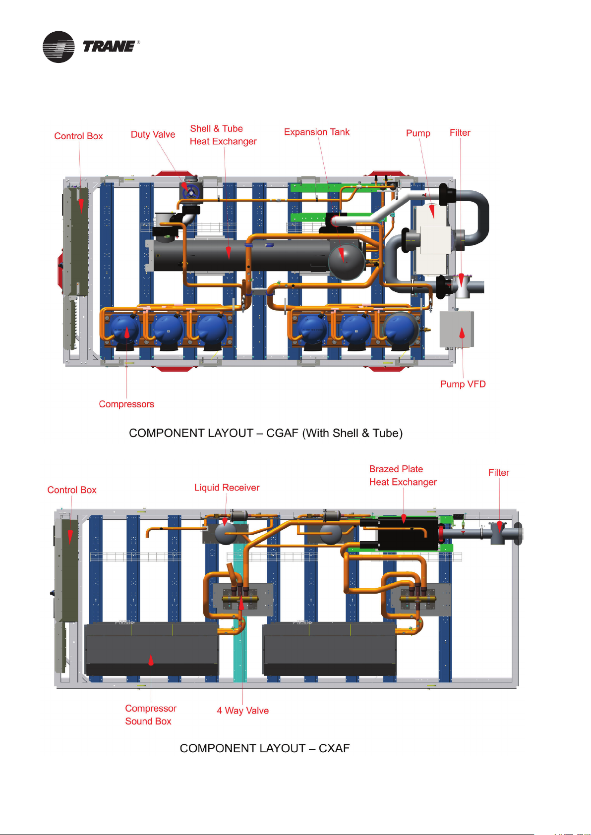
Typical CGAF / CXAF Components location
28
CG-SVX039B-GB
Page 29

Installation Requirements
Location Requirements
Sound consideration
The most effective form of acoustical isolation is to
locate the unit away from any sound sensitive area.
Structurally transmitted sound can be reduced by
elastomeric vibration eliminators. Spring isolators are not
recommended. Consult an acoustical engineer in critical
sound applications.
For maximum isolation effect, isolate water lines and
electrical conduit. Rubber isolated piping hangers can
be used to reduce the sound transmitted through water
piping. To reduce sound transmitted through electrical
conduit, use flexible electrical conduit.
EU and Local Regulations codes on sound emissions
should always be considered. Since the environment
in which a sound source is located affects the sound
pressure, unit placement must be carefully evaluated.
Clearances
When installing the unit, provide enough space around
the unit to allow the installation and maintenance
personnel unrestricted access to all service points.
Unobstructed flow of condenser air is essential to
maintain chiller capacity and operating efficiency. When
determining unit placement, give careful consideration to
ensuring a sufficient air flow across the condenser coils
heat-transfer surface.
In case of enclosure around the unit, the height of the
enclosure must not be higher than the unit itself. If the
enclosure is higher than the unit, restrictive airflow
louvers should be fitted to ensure fresh air supply.
Installation Responsibilities
Generally contractor must do the following Items when
installing a CGAF / CXAF unit:
1. Install the unit on a flat foundation strong enough
to support unit loading and level (within 5 mm
across the length and width of the unit).
2. Install the units as per instructions contained in
this manual.
3. Where specified, provide and install valves in
the water piping upstream and downstream of
the evaporator water connections, to isolate the
evaporator for maintenance, and to balance and
trim the system.
4. Furnish and install a water flow prove device and/
or auxiliary contacts to prove chiller water flow.
5. Furnish and install water pressure gauges in the
inlet and outlet of the evaporator water box.
6. Supply and install an air vent cock to the top of
the evaporator or evaporator piping.
7. Furnish and install strainers ahead of all pumps
and automatic modulating valves.
8. Provide and install field wiring according to
schematics provided in the control panel.
9. Install heat tape and insulate the chilled water
lines and any other portion of the system, as
required, to prevent sweating under normal
operating conditions or freezing during low
ambient temperature conditions.
10. Ensure that the compressor and compressor
heaters have been operating for a minimum of
24 hours before starting. Failure to do so may
result in equipment damage.
11. Start the unit under supervision of a qualified
service technician.
Lifting and Moving Instructions
A specific lifting method is recommended, which can be
described as follow:
1. Lifting points are built into the unit, see lifting
instruction label on the unit.
2. Slings and spreader bar must be provided by
crane operator and attached on the lifting points.
3. Use the 4 rigging points which are built into the
unit.
4. The minimum lifting capacity of each sling as
well as the spreader bar must be higher than the
tabulated unit shipping weight.
CAUTION! Lift and handle with care. Avoid shocks while
handling.
Details of lifting instruction and container pull out are
given in the drawings specific for lifting and handling
shipped with the unit.
WARNING! Heavy Objects! Ensure that all the lifting
equipment used is properly rated for weight of the
unit being lifted. Each of the cables (chains or slings),
hooks, and shackles used to lift the unit must be capable
of supporting the entire weight of unit. Lifting cables
(chains or slings) may not be the same length. Adjust as
necessary for even unit lift. Other lifting arrangements
could cause equipment or property damage. Failure
to follow instructions above or properly lift unit could
result in unit dropping and possibly crushing operator/
technician which could result in death or serious injury.
WARNING! Improper Unit Lift! Test lift unit approximately
10 cm to verify proper center of gravity lift point. To avoid
dropping of unit, reposition lifting point if unit is not level.
Failure to properly lift unit could result in unit dropping
and possibly crushing operator/technician which could
result in death or serious injury and possible equipment
or property- only damage.
CG-SVX039B-GB
29
Page 30

Installation Requirements
117.6
159
9.6
Dimension and Weights
Dimensions details, dimensions of hydraulic
connections, electrical connections, isolator positioning,
specific features for heat recovery and free cooling
are included in submittals and diagrams provided in
documentation package.
Center of Gravity
See instructions on lifting drawings available on request.
Unit Isolation and Leveling
Provide a foundation with sufficient strength and mass
to support the unit operating weight (that is, including
completed piping, full operating charges of refrigerant
and oil, and water). Refer to unit operating weights.
The unit must be leveled within 5 mm over its length
and width. Use shims as necessary to level the unit. For
additional reduction of sound and vibration, install the
optional elastomeric isolators.
Elastomeric Isolators Installation
(Optional)
Isolators are ready to install. Mountings have to
be placed on a rigid and level foundation. External
equipment should not transmit additional vibration to
the chiller. The position of elastomeric isolator and
weight per point are given in the Neoprene isolators
installation drawing which is supplied with the chiller.
Wrong placement along the unit may result in excessive
deflection.
Isolator Pads Installation (Optional)
Isolators are ready to install. Mountings have to
be placed on a rigid and level foundation. External
equipment should not transmit additional vibration to
the chiller. The position of pads isolator is given in the
pad isolators installation or selection drawing which is
supplied with the chiller.
Figure 3 – Isolator pads
90
450
8
1. Secure the isolators to the mounting surface using
the mounting slots in the isolator’s base plate.
Do NOT fully tighten the isolators mounting bolts at
this time. See the isolators submittals for isolators
location, maximum weights, and isolators diagrams.
2. Align the mounting holes in the base of the unit
with the threaded positioning pins on the top of the
isolators.
3. Install the unit on the isolators and secure the
isolators to the unit with a nut. The maximum
isolators deflection should be 13 mm.
4. Level the unit carefully. Fully tighten the isolator
mounting bolts.
Figure 2 – Elastomeric Isolator
40.6
127
63.5
14.2
16
70
12.7
30
CG-SVX039B-GB
Page 31

Evaporator Piping
Evaporator water connections are grooved. Thoroughly
flush all water piping to the unit before making the final
piping connections to the unit.
Components and layout will vary slightly, depending on
the location of connections and the water sources.
CAUTION Equipment Damage! If using an acidic
commercial flushing solution, construct a temporary
bypass around the unit to prevent damage to internal
components of the evaporator.
CAUTION Proper Water Treatment! The use of untreated
or improperly treated water in a chiller may result
in scaling, erosion, corrosion, algae or slime. It is
recommended that the service of a qualified water
treatment specialist be engaged to determine what
water treatment, if any, is required. Trane assumes
no responsibility for equipment failures which results
from untreated or improperly treated water or saline or
brackish water.
Drainage
Locate the unit near a large capacity drain for water
vessel draining down during shutdown or repair.
Condensers and evaporators are provided with drain
connections. Refer to “Water Piping.” All local and
national codes apply.
Water Treatment
In the evaporator the following material are in contact
with water:
• Plate material: AISI 316 EN 10028-7 - 1.4401
+2B/2R
• Connection: AISI 316 EN 10272 -
1.4401/1.4404/1.4435/1.4436 - 1E
• Braze alloy: EN-13388, ISO Copper CU-HCP
In Shell and Tube evaporator the following material are
in contact with water:
• Copper tube
• Carbon steel
• Polypropylene baffles
• EPDM rubber gaskets on baffles
• Stainless steel rivets
• Tie rod in carbon steel with galvanized finish
For the heater, the copper ring gasket’s.
When the unit is supplied with hydraulic module, the
following additional materials are in contact with water:
• Pump frame and connections are made of cast
iron
• Water pipes are made of carbon steel
• Pipe sealings are made of EPDM rubber
(ethylene propylene diene monomer rubber)
• Pump sealings are made of silicon carbide
• Straine
r is made of stainless steel
Dirt, scale, products of corrosion, and other foreign
material will adversely affect heat transfer between the
water and system components. Foreign matter in the
chilled-water system can also increase pressure drop and
consequently, reduce water flow. Proper water treatment
must be determined locally, depending on the type of
system and local water characteristics.
Neither salt nor brackish water is recommended for use
in Trane air-cooled chillers. Use of either will lead to an
unpredictably shorter life cycle. Trane encourages the
employment of a reputable water treatment specialist,
familiar with local water conditions, to assist in this
determination and in the establishment of a proper water
treatment program.
If calcium chloride is used for water treatment, an
applicable corrosion inhibitor must also be used. Failure
to do so may result in damage to system components.
Do not use untreated or improperly treated water.
Equipment damage may occur.
Piping
Piping components include all devices and controls
used to provide proper water system operation and
unit operating safety. A typical CGAF / CXAF evaporator
piping is shown below.
Figure 4 – Unit typical water circuit
1 = Pressure gauges: show entering and leaving water
pressure
2 = Balancing valve: adjusts water flow.
3 = Air purge allows to remove the air from the water
circuit during fill up.
4 = Stop valves: isolate chillers and water circuiting
pump during maintenance operations.
5 = Thermometers: indicate chilled water entering and
leaving temperatures.
6 = Expansion compensators: avoid mechanical stress
between chiller and piping installation.
7 = Stop valve located on the outlet connection: used
to measure the water pressure inlet or outlet of
evaporator.
CG-SVX039B-GB
31
Page 32

Evaporator Piping
8 = Strainer: avoid to get heat exchangers dirty. All
installation must be equipped with efficient strainer
in order that only clean water enters into exchanger.
If there is no strainer, reserve will be formulated by
the Trane technician at the start-up of the unit. The
trainer used must be able to stop all particles with a
diameter greater than 1 mm.
9 = Draining: used as the draining the plate heat
exchanger.
10 = Do not start the unit with low water volume or not
enough pressurized circuit.
Note: A pressure switch device to detect lack of water
is not included in the pump package. Installation of this
type of device is highly recommended to avoid sealing
damage due to operation of pump without enough
water.
An air vent is located on top of the evaporator at the
chiller water outlet. Be sure to provide additional air
vents at the highest points in the piping to remove air
from the chilled water system. Install necessary pressure
gauges to monitor the entering and leaving chilled water
pressure.
Provide shut off valves in lines to the gauges to isolate
them from the system when they are not in use. Use
rubber vibration eliminators to prevent vibration
transmission through the water lines.
If desired, install thermometers in the lines to monitor
entering and leaving water temperatures.
Install a balancing valve in the leaving water line to
control water flow balance.
Install shutoff valves on both the entering and leaving
water lines so that the evaporator can be isolated for
service.
It is mandatory to place a flow switch device at the outlet
of the unit and to link it with the control of the unit (see
wiring diagrams shipped with the unit).
CAUTION! The chilled-water connections to the
evaporator are to be “grooved pipe” type connections.
Do not attempt to weld these connections, because the
heat generated from welding can cause microscopic and
macroscopic fractures on the heat exchanger connection
that can lead to premature failure of the connection. An
optional grooved pipe stub and coupling should be used
for welding on flanges.
Entering Chilled Water Piping
• Air vents to bleed the air from the system (to be placed
on the highest point)
• Water pressure gauges with shutoff valves
• Vibration eliminators
• Shutoff (isolation) valves
• Thermometers if desired (temperature readings
available on chiller controller display)
• Clean-out tees
• Pipe strainer
Leaving Chilled Water Piping
• Air vents to bleed the air from the system (to be placed
on the highest point)
• Water pressure gauges with shut off valves
• Vibration eliminators
• Shutoff (isolation) valves
• Thermometers (temperature readings available on the
chiller controller display)
• Clean-out tees
• Balancing valve
• Flow Proving Device
Pressure Gauges
Install field-supplied pressure components. Locate
pressure gauges or taps in a straight run of pipe; avoid
placing them near elbow (at least at 10 pipe diameter
from discontinuity).
To read manifold pressure gauges, open one valve and
close the other (depending on the side of the desired
reading), this eliminate errors resulting from differently
calibrated gauges installed at unmatched elevations.
Evaporator Flow Switch
Specific connection and schematic wiring diagram
are shipped within the unit. Some piping and control
schemes, particularly those using a single water pump
for both chilled and hot water, must be analyzed to
determine how and/or if a flow sensing device will
provide the desired operation.
To prevent damage to chilled-water components, do not
allow evaporator pressure (maximum working pressure)
to exceed 10 Bar. The maximum service pressure
depends on free cooling type and potential pump
package option. The value of max service pressure is
indicated on unit nameplate.
32
CG-SVX039B-GB
Page 33

Evaporator Piping
Flow Switch Installation – Typical
Requirements
1. Mount the switch upright, with a minimum of
10 pipes diameters of straight horizontal run on
each side. Do not install close to elbows, orifices,
or valves. The arrow on the switch must point in the
direction of the flow. For additional information,
consult the flow switch information sheet coming
with the part.
2. To prevent switch fluttering, remove all air from the
water system. Tracer UC800 provides a 6 second
time delay after a “loss-of-flow” diagnostic before
shutting the unit down. Contact a Trane service
representative if nuisance machine shutdowns
persist.
3. Adjust the switch to open when water flow falls
below nominal values. Evaporator data is given
on the General Information Section. Flow Switch
contacts are closed on proof of water flow.
CAUTION! Control voltage from the chiller to the flow
proving device is 110V AC.
Note: In case of winter water drainage for freeze
protection, it is mandatory to disconnect the
evaporator’s heaters to protect them from burning due
to overheat. It is also mandatory to fulfill the drainage,
using pressurized air, and ensure that no water stays in
the evaporator during winter season.
The minimum volume can be determined by using the
following formula:
Volume = Cooling capacity x Time x highest capacity step
(%) / Specific heat / Dead band
Minimum operating time = 120 seconds
Specific heat = 4.18 kJ / kg
Average Dead band = 3°C (or 2°C)
Note: To estimate the biggest step, it is usually
more reliable to make a selection at lower ambient
temperature where efficiency is higher and compressors
steps bigger. It is also essential to take into account the
brine specific heat, in case of the use of glycol.
Process applications will need more water volume to
minimize the water temperature fluctuation at part load.
Expansion tank (option)
The factory-installed expansion tank initial pressure
should be adjusted about 0.2 bar lower than the static
pressure of the circuit at the pump inlet. The expansion
tank volume has been selected for typical loop volume.
It is recommended to check the expansion tank volume
with the installation information.
The following data is required:
C = Water capacity of the circuit
e = Expansion coeffi cient (difference between max and
min water temperature, in operation or not)
Pi = Initial pressure of the expansion tank
Pf = Final pressure: Max is given by the pressure relief
valve
Minimal installation water content
The water volume is an important parameter because
it allows as table chilled water temperature and avoids
short cycle operation of the compressors.
Parameters which influence the water temperature
stability
− Water loop volume
− Load fluctuation
− Number of capacity steps
− Compressors rotation
− Dead band (adjusted on chiller controller)
− Minimum time between 2 starts of a
compressor
Minimum water volume for a
comfort application
For comfort application we can allow water temperature
fluctuation at part load. The parameter to take into
account is the minimum operating time of the
compressor. In order to avoid lubrication problem
on a scroll compressor it must run at least 2 minutes
(120 seconds) before it stops.
Minimum Volume of expansion tank = (C x e)/(1-Pi/Pf)
Expansion coefficient of water various temperatures
°C e
0 0.00013
10 0.00027
20 0.00177
30 0.00435
40 0.00728
50 0.01210
Water loop and expansion tank volume
- Water loop CGAF 080 HE/XE, CGAF 090: 607 l
- Water loop CGAF 140-190: 777 l
Expansion tank volume (option): 50 l
Note: Maximum pressure of the circuit is 400 kPa with
pump package and 1000 kPa without.
CG-SVX039B-GB
33
Page 34

Installation - Mechanical
5
25
125
5 50
Evaporator Pressure Drop (kPa)
Water Flow Rates (L/s)
Evaporator Water Pressure Drop
1-106
2-122
3-138
4-166
5-194
6-222
7-250
8-278
9-294
10-3511
11-3519
1
7
4
3
5
8
9
10
2
6
20
3025 4015
10
15
20
50
75
100
BPHE - 1 to 9 - DFX650 Number of plates
Shell & Tube - 10 & 11
1
7
4
3
5
8
9
10
2
6
20
3025 4015
10
15
20
50
75
100
BPHE - 1 to 9 - DFX650 Number of plates
Shell & Tube - 10 & 11
1
7
4
3
5
8
9
10
2
6
20
3025 4015
10
15
20
50
75
100
BPHE - 1 to 9 - DFX650 Number of plates
Shell & Tube - 10 & 11
1
7
4
3
5
8
9
10
2
6
20
3025 4015
10
15
20
50
75
100
BPHE - 1 to 9 - DFX650 Number of plates
Shell & Tube - 10 & 11
Figure 5 – CGAF / CXAF Evaporator Water Pressure Drop (BPHE, Shell & Tube)
Note: Water pressure drop are for pure water. Limit of water flow are limit of the curves.
34
CG-SVX039B-GB
Page 35

Schematic pump package
Installation – Mechanical
Chiller can be ordered with an optional integrated hydraulic module. In this case, chiller will be provided with the
following components factory mounted and tested:
• Centrifugal water pump, Low pressure or High pressure (option)
• Water strainer to protect the pump against impurities in the circuit
• Expansion module with expansion vessel and pressure relief valve sufficient to ensure the expansion of the water
loop ability
• Thermal insulation for antifreeze protection
• Balancing valve (Optional) for equilibrate the flow of water circuit
• Drain valve
• Temperature sensor
Note: A pressure switch device to detect lack of water is not included in the pump package. Installation of this type of
device is highly recommended to avoid sealing damage due to operation of pump without enough water.
Pump package schematics is supplied in the documentation set shipped with the unit.
CG-SVX039B-GB
35
Page 36

Schematic pump package
0
50
100
150
200
250
5 10 15 20 25 30 35 40 45 50
Avaiable Pressure(kPa)
Water Flow Rates (L/s)
Standard Head - Standard Efficiency
1. 80-90SE
2. 100SE
3. 110SE
4. 130-140SE
5. 150SE
6. 165SE
7. 180SE
8. 190SE
9. 90/100-SE-T
10. 110/130-SE-T
11. 140/150-SE-T
Max Flow 80SE
6
7
8
9
10
11
Max Flow 80SE
6
7
8
9
10
11
1
2
3
4
5
1 to 8 - BPHE Evaporat or
9 to 11 - Shell & Tube Evaporator
50
100
150
200
250
300
350
5 10 15 20 25 30 35 40 45 50
Avaiable Pressure(kPa)
Water Flow Rates (L/s)
High Head - Standard Efficiency
1. 80-090SE
2. 100SE
3, 110SE
4. 130SE
5. 140SE
6. 150SE
7. 165SE
8. 180SE
9. 190SE
10. 90/100/110/130-SE-T
11. 140/150-SE-T
1
8
5
7
6
2
3
4
9
Max Water Flow 80SE
11
10
1
8
5
7
6
2
3
4
9
Max Water Flow 80SE
11
10
10
1 to 9
- BPHE Evaporator
10 & 11 - Shell & Tube Evaporator
Pump Curves
In the figures below are described pump curves (Standard Head and High head) for the whole CGAF / CXAF unit
range.
Figure 6 – Pump Curve - Sizes 090-190 –Standard / High Head - BPHE / Shell & Tube Evaporator
36
CG-SVX039B-GB
Page 37

Evaporator Waterside
Freeze Protection
Depending on the ambient temperature the unit may be
exposed to freeze, there are multiple options for freeze
protection. They are listed in order of highest ambient
(least freeze protection) to the lowest ambient (most
freeze protection).
For all chiller running with water under cold ambient
temperature (below 0°C), it is extremely important to
keep full water flow in the evaporator for an extended
time after last compressor stops. This will protect brazed
plate evaporator from freezing by refrigerant migration.
This is why evaporator water pump output relay must
be used to control the chilled water pump. This is not
mandatory if glycol is used with protection down to
lowest ambient expected.
1. Water pump and heaters
a. Heaters are factory installed on brazed plates
evaporator. They will protect it from freezing in
ambient temperatures down to -18°C.Heaters are
installed on the water piping and on the pumps of
units equipped with hydraulic module.
b. Install heat tape on all water piping, pumps, and other
components that may be damaged if exposed to
freezing temperatures. Heat tape must be designed
for low ambient temperature applications. Heat tape
selection should be based on the lowest expected
ambient temperature.
c. Tracer™ UC800 controller can start the pump(s) when
freezing conditions are detected. For this option the
pumps must be controlled by the CGAF / CXAF unit
and this function validated on the chiller / Heat pump
controller.
d. Water circuit valves need to stay open at all times.
Note: Water pump control and heater combination
will protect the evaporator down to any ambient
temperature provided power is available to the
pump and the UC800 controller. This option will NOT
protect the evaporator in the event of power failure
to the chiller unless backup power is supplied to the
necessary components.
OR
2. Freeze inhibitor
a. Freeze protection can be accomplished by adding
sufficient glycol to protect against freezing down to
the lowest ambient expected.
b. See “evaporator glycol requirement” section for
guidance on determining the glycol concentration.
Note: Use of glycol type antifreeze reduces the cooling
capacity of the unit and must be considered in the
design of the system specifications.
CG-SVX039B-GB
CAUTION! When using freeze inhibitor, never fill the
system with pure glycol.
Always fill the system with diluted solution. Maximum
concentration of glycol is 40%. Higher glycol
concentration will damage pump seal.
OR
3. Drain water circuit
For ambient temperatures below -20°C and for those
installation not including either option 1 or 2 above
described
a. Shut off power supply to unit and to all heaters.
b. Purge the water circuit
c. Blow out the evaporator to ensure that no liquid is left
inside the evaporator and the water lines. Drain the
pump.
Note: It is not recommended to drain the water circuit
for the following reasons.
1. The water circuit will rust and its lifetime could be
reduced.
2. Water will remain in the bottom of the plate heat
exchangers and freeze damage could occur
CAUTION! Evaporator damage!
If insufficient concentration or no glycol is used, the
evaporator water pumps must be controlled by the
UC800 to avoid severe damage to the evaporator due
to freezing. A power loss of 15 minutes during freezing
can damage the evaporator. It is the responsibility of
the installing contractor and/or the customer to ensure
that a pump will start when called upon by the chiller
controls. Please consult TRANE service for unit setting
and % of glycol required.
With factory-fitted disconnect switch option, evaporator
trace heating is taken from the live side of the isolator.
As a consequence, the heaters are energized as long as
the main switch is closed. Supply voltage to the heating
tapes is 400V.
• Avoid the use of very low or near minimum chilled
fluid flow rates through the chiller. Higher velocity
chilled fluid flow reduces freeze risk in all situations.
• Flow rates below limits have increased freeze potential
and have not been considered by freeze protection
algorithms.
• Avoid applications and situations that result in a
requirement for rapid cycling or repeated starting and
stopping of the chiller. Keep in mind that chiller control
algorithms may prevent a rapid compressor restart
after shutting down when the evaporator has been
operating near or below the LERTC (Low Refrigerant
Temperature Cutout) limit.
• Maintain refrigerant charge at appropriate levels. If
charge is in question, contactTrane service. A reduced
or low level of charge can increase the likelihood of
freezing conditions in the evaporator and/or LERTC
diagnostic shutdowns.
The warranty will be void, in case of freezing due to the
lack of use of either of these protections.
37
Page 38

Evaporator Waterside (not for free cooling version)
Low refrigeration temperature setpoint
and antifreeze setpoint on CGAF unit
control
CAUTION! The chiller is provided with standard factory
settings. It can be necessary to modify the Low Pressure
saturation Temperature and the Antifreeze Setpoint on
the unit control. Based on the following examples, it is
necessary to modify on the unit control the following
settings:
• The LP saturation temperature
• The antifreeze setpoint
Examples for:
• 7°C, the LP setting must be -4°C where the antifreeze
setting shall be 2°C
• 2°C, the LP setting must be -9°C where the antifreeze
setting shall be -4°C
• -12°C, the LP setting must be -23°C where the
antifreeze setting shall be -17°C
Figure 7 – LP setting Vs. Leaving Water Temperature setpoint
Freeze protection with glycol
It is mandatory to use a freeze inhibitor for leaving
water setpoint less or equal to 5°C. On the glycol
recommended concentration figure, you must select
concentration on or above the curve. For example, for
-4°C brine temperature, a concentration of 25% ethylene
glycol is not sufficient. The concentration must be 28%
ethylene glycol or 33% propylene glycol.
Using glycol with hydraulic module
If the glycol brine percentage is not at the recommended
percentage (greyed area), corrosion inhibitor present
in the glycol may not be efficient enough. For instance,
a glycol concentration of 15% will provide freeze
protection to the unit down to -5°C, but it might generate
additional corrosion.
Lp setting -
2
Lp setting
Lp setting
15
38
CG-SVX039B-GB
Page 39

Evaporator Waterside (not for free cooling version)
Figure 8 – Glycol percentage recommendation curve
1 = Critical risks of freezing
2 = Efficient freeze protection
3 = Ethylene glycol
4 = Propylene glycol
% = Glycol percentage (mass concentration)
°C = Glycol or water temperature
CAUTION!
1. Additional glycol beyond the recommendations will adversely affect unit performance. The unit efficiency will be
reduced and the saturated evaporator temperature will be reduced. For some operating conditions this effect can
be significant.
2. If additional glycol is used, then use the actual % glycol to establish the low refrigerant cutout set point with Trane
service advice.
3. The minimum low refrigerant cutout set point allowed is - 20.6°C. This minimum is established by the solubility
limits of the oil in the refrigerant.
4. With glycol application, ensure that there is no fluctuation of brine flow versus Order Write Up value, as a
reduction of flow will adversely affect unit performance and behaviour.
5. Full unit simulation is required for proper prediction of unit performance for specific operating conditions.
For information on specific conditions, contact Trane.
CG-SVX039B-GB
39
Page 40

General Electrical Recommendations
Electrical Parts
When reviewing this manual keep in mind.
• All field-installed wiring must be in
accordance with local regulations, CE
directives and guidelines. Be sure to satisfy
proper equipment grounding requirements
according CE
• The following standardized values - Maximum
Amps - Short Circuit Amps - Starting Amps are
displayed on unit nameplate.
• All field-installed wiring must be checked for
proper terminations, and for possible shorts or
grounds.
Note: Always refer to wiring diagrams shipped with
chiller or unit submittal for specific electrical schematic
and connection information.
Important: To prevent control malfunctions, do not run
low voltage wiring (<30V) in conduit with conductors
carrying more than 30 volts.
WARNING! Hazardous Voltage with Capacitor!
Disconnect all electric power, including remote
disconnects and discharge all motor start/run and
AFD (Adaptive Frequency TM Drive) capacitors before
servicing. Follow proper lockout/tagout procedures to
ensure the power cannot be inadvertently energized.
• For variable frequency drives or other energy
storing components provided by Trane or
others, refer to the appropriate manufacturer’s
literature for allowable waiting periods
for discharges capacitors. Verify with an
appropriate voltmeter that all capacitors have
discharged
• DC bus capacitors retain hazardous voltages
after input power has been disconnected.
Follow proper lockout/tagout procedures to
ensure the power cannot be inadvertently
energized
• After disconnecting input power, wait five (5)
minutes for units which are equipped with EC
fans and wait twenty (20) minutes for units
which are equipped with variable frequency
drive (0V DC) before touching any internal
components.
• Failure to follow these instructions could result
death or serious injury
For additional information regarding the safe discharge
of capacitors, see “Adaptive Frequency™ Drive (AFD3)
Capacitor Discharge” and BAS-SVX19B-E4.
Hazardous Voltage – Pressurized Burning Fluid!
Before removing compressor terminal box cover for
servicing, or servicing power side of control panel,
CLOSE COMPRESSOR DISCHARGE SERVICE VALVE
and disconnect all electric power including remote
disconnects. Discharge all motor start/run capacitors.
Follow lockout/tagout procedures to ensure the
power cannot be inadvertently energized. Verify with
an appropriate voltmeter that all capacitors have
discharged.
The compressor contains hot, pressurized refrigerant.
Motor terminals act as a seal against this refrigerant.
Care should be taken when servicing NOT to damage or
loosen motor terminals.
Do not operate compressor without terminal box cover
in place.
Failure to follow all electrical safety precautions could
result in death or seriously injure.
CAUTION! To avoid corrosion, overheating or general
damage, at terminal connections, unit is designed for
copper mono-conductors only. In case of multiconductor
cable, an intermediate connection box must be
added. For cable with alternative material, bi-material
connecting devices are mandatory. Cable routing inside
control panel should be made case by case by installer.
Do not allow conduit to interfere with other components,
structural members or equipment. Control voltage
(115V) wiring in conduit must be separate from conduit
carrying low voltage (<30V) wiring. To prevent control
malfunctions, do not run low voltage wiring (<30V) in
conduit with conductors carrying more than 30V.
WARNING! The Warning Label is displayed on the
equipment and shown on wiring diagrams and
schematics. Strict adherence to these warnings must be
observed. Failure to do so may result in personal injury
or death.
CAUTION! Units must not be linked to the neutral
wiring of the installation. Units are compatible with the
following neutral operating conditions:
TNS IT TNC TT
Standard Standard** Special Standard*
* Differential protection should be suited for industrial
machinery with current leak which can be higher than
500 mA (several motors and frequency drives).
** Filter RFI disconnect on VPF and EC fan.
40
CG-SVX039B-GB
Page 41

General Electrical Recommendations
Electrical data
To get the following electrical data details: Refer to General Data tables for each unit configuration and size.
− Maximum Power input (kW)
− Unit rated amps (Max comp + Fan + Control)
− Unit start up amps (Starting Amps of the largest comp + RLA of 2nd comp + RLA of all fans+ control)
− Compressor Power factor
− Disconnect switch size (A)
− Short Circuit Rating for all sizes =15 kA
Wiring diagrams are shipped with unit and can be found in the unit control panel.
Note: Rating is made for 400 V, 3 phases, 50 Hz power supply.
CG-SVX039B-GB
41
Page 42

Installer-Supplied Components
Customer wiring interface connections are shown in
the electrical schematics and connection diagrams that
are shipped with the unit. The installer must provide the
following components if not ordered with the unit:
• Power supply wiring (in conduit) for all fieldwired connections
• All control (interconnecting) wiring (in conduit)
for field supplied devices
• Fused-disconnect switches
Power Supply Wiring
All power supply wiring must be sized and selected
accordingly by the project engineer in accordance
with standard IEC 60364. All wiring must comply with
local codes. The installing (or electrical) contractor
must provide and install the system interconnecting
wiring, as well as-the power supply wiring. It must be
properly sized and equipped with the appropriate fusedisconnect switches. The type and installation location(s)
of the fused-disconnect switches must comply with all
applicable codes.
Cut holes into the sides of the control panel for the
appropriately-sized power wiring conduits. The wiring
is passed through these conduits and connected to the
terminal blocks.
To provide proper phasing of 3 phase input, make
connections as shown in field wiring diagrams and as
stated on the yellow WARNING label in the starter panel.
Proper equipment grounds must be provided to each
ground connection in the panel.
CAUTION! Customer wiring interface connections are
shown in the electrical schematics and connection
diagrams that are shipped with the unit. The installer
must provide the following components if not ordered
with the unit.
WARNING! To prevent injury or death, disconnect all
electrical power sources before completing wiring
connections to the unit.
CAUTION! The use of copper mono-conductors is the
preferred solution to avoid corrosion and overheating
at terminal connections.
Control Power Supply
Chiller is provided with control power transformer, it
is not necessary to provide additional control power
voltage to the unit.
Heater Power Supply
The evaporator shell is insulated from ambient air and
protected from freezing for temperature down to -20°C
by two thermostatically-controlled immersion heaters
combined with evaporator pumps activation through
Tracer UC800. Whenever the ambient temperature
drops below 0°C the thermostat energizes the heaters
and the Tracer UC800 activates the pumps. If ambient
42
temperatures below -20°C are expected, contact your
Trane local office.
CAUTION! The control panel main processor does
not check for loss of power to the heat tape nor does
it verify thermostat operation. A qualified technician
must frequently verify power to the heat tape and
confirm operation of the heat tape thermostat, to avoid
catastrophic damage to the evaporator.
CAUTION! With factory-fitted disconnect switch, trace
heating is taken from the live side of the isolator so
power remains on. Supply voltage to the heating tapes
is 400V.
Don’t energize heaters without water. In case of winter
water drainage for freeze protection, it is compulsory to
disconnect the evaporator heaters to protect them from
burning due to overheat.
Water Pump Power Supply
Provide power-supply wiring with fused disconnect
switch(es) for the chilled water pump(s).
Interconnecting Wiring
Chilled-Water Flow (Pump) Interlock
CGAF/CXAF requires a field-supplied, control-voltage
contact input through a flow proving switch (6S51) and
an auxiliary contact (6K51). Connect the proving switch
and auxiliary contact to terminal 2 connector J2 cards
(1A11). Refer to the field wiring diagram for details.
Chilled-Water Pump Control
An evaporator water-pump output relay closes when
the chiller is given a signal to go into the AUTO mode
of operation from any source. The contact is opened to
turn off the pump in the event of most machine-level
diagnostics, to prevent the buildup of pump heat.
CAUTION! The evaporator water pump output relay
must be used to control the chilled water pump and to
benefit from the water pump timer function at startup
and shutdown of the chiller. This is required when
the chiller is in operation under freezing conditions,
especially if the chilled water loop does not contain
glycol.
CAUTION! Refer to Freeze Protection section for
information about the evaporator circulating pump.
Alarm and Status Relay Outputs
(Programmable Relays)
See CGAF / CXAF User Guide for alarm and status relay
outputs.
EDLS and ECWS Analog Input Signal
Wiring Details
See CGAF / CXAF User Guide for EDLS and ECWS.
CG-SVX039B-GB
Page 43

Operating Principles
This section contains an overview of the operation
of CGAF / CXAF air-cooled liquid chiller / Heat Pump
equipped with microcomputer-based control systems.
It describes the overall operating principles of the CGAF
chiller / CXAF Heat Pump.
Note: To ensure proper diagnosis and repair, contact a
qualified service organization if a problem could occur.
General
The Model CGAF / CXAF units are scroll compressor(s),
single or dual circuit, air-cooled liquid chillers. These
units are equipped with unit-mounted starter/control
panels and operate with R410A refrigerant.
The basic components of a CGAF / CXAF unit are:
• Unit-mounted panel containing starter and
Tracer UC800 controller and Input/Output
LLIDS
• Scroll compressors
• Brazed plate / Shell & Tube evaporator
• Air-cooled MCHE / Fin & tube condenser with
sub cooler
• Electronic Expansion Valve (EEXV)
• Related interconnecting piping
Refrigerant Cycle
The refrigeration cycle of the Model CGAF chiller / CXAF
Heat Pump is conceptually similar to other Trane aircooled chiller products. The CGAF chiller / CXAF Heat
Pump uses a brazed plate / Shell & Tube evaporator
and an air-cooled MCHE / Fin & tube condenser. The
compressors use suction gas cooled motors and an
oil management system to provide almost oil-free
refrigerant to the condenser and evaporator for
maximum heat transfer while lubricating and sealing
compressor rotors and bearings. The lubrication system
helps to assure long compressor life and contributes to
quiet operation.
Refrigerant condenses in the MCHE / Fin & tube
air-cooled heat exchanger. Liquid refrigerant is metered
into the brazed plate or Shell and Tube evaporator
using an electronic expansion valve to maximize chiller
efficiency at full and part load operation.
The CGAF chiller / CXAF Heat Pump is equipped with a
unit-mounted starter and control panel. Microprocessor
based unit control modules (Trane Tracer™UC800)
provide accurate chilled water control and providing
monitoring, protection and adaptive limit functions.
The adaptive nature of the controls intelligently prevent
the chiller from operating outside of its limits, or
compensates for unusual operating conditions while
keeping the chiller running rather than simply shutting
off the chiller. If problems do occur, the UC800 controls
provide diagnostic messages to help the operator in
troubleshooting.
Oil System
The oil is efficiently separated inside the scroll
compressor and will remain in the scroll compressor
during all run cycles. Between 1-2% of the oil circulates
around with the refrigerant.
See compressor section for oil level information.
Condenser and Fans
The air cooled micro-channel condenser coils use
all aluminum brazed fin construction and Fin & tube
condenser coils use Copper tube and aluminum fin
construction.
The MCHE coil is composed of three components: the
flat micro channel tube, the fins located between the
micro-channel tubes, and two refrigerant manifolds.
Coils can be cleaned with high pressure water (see
Condenser Coils maintenance for instructions).
Whereas Fin & Tube coil is composed of four
components: the holding frame, Circular tube, U-bends
joining the tube ends, the aluminum fins located above
the tubes, and two refrigerant Headers. Coils can be
cleaned with high pressure water (see Condenser Coils
maintenance for instructions).
The condenser coils has an integral sub-cooling circuit.
Condensers are factory proof and leak tested at 45 bars.
Direct-drive vertical-discharge airfoil condenser AC/EC
fans are dynamically balanced.
CG-SVX039B-GB
43
Page 44

Operating Principles
This section describes the overall flow chart principle for CGAF / CXAF. Detailed information for a given order is
supplied with order package documentation.
Figure 9 – Example of Typical Refrigerant System Schematic & Oil Lube Circuit Schematic for CGAF - BPHE
44
CG-SVX039B-GB
Page 45

Operating Principles
Figure 10 – Example of Typical Refrigerant System Schematic & Oil Lube Circuit Schematic for CGAF S&T
CG-SVX039B-GB
45
Page 46

Operating Principles
Figure 11 – Example of Typical Refrigerant System Schematic & Oil Lube Circuit Schematic for CXAF - BPHE
46
CG-SVX039B-GB
Page 47

Figure 12 – Operating Map for CGAF / CXAF
-30
-20
-10
0
10
20
30
40
50
60
-20 -10 0 10 20
Ambient Temperature/C
Leaving Water Temperature / C
CXAF - Cooling Map SE/HEat
EC Fan
AC Fa n
AC/EC Fan Min.Load
-20
-15
-10
-5
0
5
10
15
20
25
30
35
40
5 10 15 20 25 30 35 40 45 50 55 60
Ambient Temperature/C
Leaving Water Temperature / C
CXAF - Heating Map Full Load
SE EC Fan
SE AC Fan
HE at AC & EC Fa n
HEat
-20
-15
-10
-5
0
5
10
15
20
25
30
35
40
5 10 15 20 25 30 35 40 45 50 55 60 65
Ambient Temperature/C
Leaving Water Temperature / C
CXAF - Heating Map Min. Load
SE EC Fan
SE AC Fan
HEa t AC & E C Fan
HEat
Operating Map
Notes:
- Minimum start-up/operation at low ambient air temperature based on wind speed lower than 2m/s.
- Maximum ambient operation is for unit at 12°C/7°C operating conditions.
- The curve of limit current may vary from one machine size to another, but it will always be a parallel curve to that
CG-SVX039B-GB
shown in the operating map.
47
Page 48

Total Heat Recovery
The total heat recovery option includes:
− A Common braze plate heat exchanger for both
refrigeration circuits installed in serial between
with the compressor discharge and air-cooled
condenser, allowing mix of liquid and gas at the
outlet leaving to condenser coil.
− MCHE Condenser coil with EC fan motor only to
maintain the discharge pressure above the THR
water outlet condensing temperature.
CAUTION! Discharge gas temperature can reach 130°C,
may resulting in overheating of the heat recovery water
if there is no appropriate flow.
CAUTION! For the first start, Total Heat Recovery water
temperature sensors should be checked to make sure
that they are not reversed.
CAUTION! A field-installed safety or relief valve on the
water side is required with the total heat recovery to
prevent risks resulting from a failure of the unit control.
− A 3-way modulating valve factory installed on
the water side to manage the leaving water
temperature and required high discharge
pressure.
− Two temperature sensors for inlet and outlet hot
water temperature control.
− Freeze protection heaters (option).
Piping recommendations
A 1 to 1.6 mm strainer must be installed close to the
total heat recovery heat exchanger entering water line to
protect the heat exchanger.
Insulate water lines and other portions of the heat
recovery water loop to prevent heat loss and potential
injury due to exposure to a hot surface.
The heat exchanger is used both as a desuperheater and
a condenser of compressors discharge gas. Refrigerant
leaves the total heat recovery braze plates heat
exchanger as a mixture of gas and liquid. The air-cooled
condenser is used to finalize the condensation and
provide a subcooled refrigerant to the expansion valve.
Main stream of refrigerant flow in these units is through
filter drier keeping bypass opening to 10% with THR Off.
This avoid oil distillation in dead branch. During THR
operation bypass valve open 100% allowing 65% of
refrigerant flow via bypass line to maintain pressure.
The heating capacity is driven by the cooling demand on
the chiller, the ambient temperature and the temperature
of the heat recovery loop. The heating capacity is
Do not use untreated or improperly treated water in the
heat recovery water loop since it will cause inefficient
operation and potential damage to the unit such as:
reduced heat transfer between water and refrigerant,
increased water pressure drop and reduced water flow.
CAUTION! : Proper Water Treatment! The use of
untreated or improperly treated water in a chiller may
result in scaling, erosion, corrosion, algae, or slime. It
is recommended that the services of a qualified water
treatment specialist be engaged to determine what
water treatment, if any, is required. Trane assumes no
responsibility for equipment failures which result from
untreated or improperly treated water, or saline or
brackish water.
optimized by a smart control of the condensing
temperature using the fans.
Water circulating inside the heat recovery heat
exchanger should never be used in food processing or as
drinking water. It must be used through a direct loop to
heat or preheat water.
Note: Ambient temperature shall be lower than THR
leaving water temperature set point to operate allowing
45% up to 116% evaporator heat recovery
Note: If the total heat recovery heat exchanger is
drained, the heater must be turned off to avoid
damaging the total heat recovery heat exchanger. The
heater should only be on when the heat recovery heat
exchanger has water in it.
Freeze protection (option)
The heat recovery condenser is insulated and a factoryinstalled heater is installed and will protect the heat
exchanger from freezing in ambient temperatures
down to -18°C. When the ambient temperature drops
to approximately 5°C, the main controller energizes the
heaters.
Note: The inlet and outlet piping should be protected
against freezing by one of the following methods:
− Install heat tape on all field installed water
piping.
− Add freeze inhibit fluid to the total heat recovery
water loop.
Table 7 – General Data for Total Heat recovery (THR) Option CGAF 080-190
CGAF CGAF CGAF CGAF CGAF CGAF CGAF CGAF CGAF CGAF
080 090 100 110 130 140 150 165 180 190
Heat Exchanger Type Stainless steel Copper Brazed plate Heat exchanger
THR Heat Exchanger model DB400
Water connection size (in) -
(mm)
Water content volume L 15.2 15.2 18.5 18.5 18.5 25.3 25.3 25.3 31.2 31.2
Additional Shipping Weight kg 155 155 165 165 165 210 210 210 245 265
Freeze protection – Electric heater
Max Power input (kW) 0.28 0.28 0.28 0.34 0.34 0.34 0.34 0.34 0.34 0.34
Max Amps (A) 0.7 0.7 0.7 0.85 0.85 0.85 0.85 0.85 0.85 0.85
3"OD –
x74
76.1
DB400
x74
3"OD –
76.1
DB400
x90
3"OD –
76.1
DB400
x90
3"OD –
76.1
DB400
x90
3"OD –
76.1
DB400
x122
3"OD –
76.1
DB400
x122
3"OD –
76.1
DB400
x122
3"OD –
76.1
DB400
x150
3"OD –
76.1
DB400
x150
3"OD –
76.1
48
CG-SVX039B-GB
Page 49

Total Heat Recovery
30 , 33.0
49 , 52.0
55 , 52.0
55 , 7.2
30 , 7.2
-
10.0
20.0
30.0
40.0
50.0
60.0
25 30 35 40 45 50 55 60
Amb Temperat ure (C)
THR LWT (C)
Figure 13 – Refrigerant Schematic THR option
THR should not be used for glycol application
on evaporator side. Minimum THR start-up water
temperature should be higher than 5°C. THR should be
used when leaving evaporator temperature is between 5
and 15.5°C.
Table 8 – Operating Map (THR) CGAF 080-190
Standard
Application
Min. outdoor air temperature 7.2 7.2
Max. outdoor air temperature 49 52
Min. leaving evaporator water
temperature
Max. leaving evaporator
water temperature
Min. leaving THR water
temperature
Max. leaving THR water
temperature
ambient
(°C) (°C)
4.4 4.4
15.6 15.6
30 30
55 55
High ambient
THR 3-way valve description
The 3-way valve is divided into 2 mains parts: the
actuator and the valve body.
Valve body
2 types of valve are used (DN50, DN65) with a Kvs
respectively of 40, **.
Kvs –value is showing the capacity of media flow of a
valve, it characterizes the volume flow (m3/h) of water
by measuring a differential pressure (bar). This value is
related to full stroke.
The 3-way valve body is connected to the system in 3
points A, B, AB as below:
Actuator overview
- Supply voltage: 24 Vac
- Actuator setting
• W1(input signal failure): 100%, actuator will
adjust to 100% position when signal input fails
(THR BP bypassed)
• W2(input signal range): LED “OFF” for 2~10V
• W3 (direction of action): LED “ON” 2V for A-AB
close, 10V for A-AB full open
Figure 14 – Total Heat Recovery Operation Map
CG-SVX039B-GB
49
Page 50

Total Heat Recovery
10
50
250
2 4 8 16 32
Pressure Drop (kPa)
Water Flow Rates (L/s)
TOTAL HEAT RECOVERY (THR) & BPHE (THR) - CGAF SE/HE/XE
1 - 080/090 - SE /HE/XE
2 - 100/110/130 - SE/HE/XE
3 - 140/150/165 - SE/HE/XE
4 - 180/190 SE/HE/XE
5 - BPH E 080/090/100/110/130/140/1
50/165/180/190 - SE /HE/XE
2
1
3
4
5
1 to 4 - Total THR Pressure Drop
5 - BPHE (THR) Pressure Drop
Refrigerant charge
When a total heat recovery is installed, refrigerant charge (kg) are as shown in the table below.
Table 9 – Refrigerant Charge (THR Option) CGAF 080-190
Refrigerant charge THR Option
CGAF-CXAF sizes 80 90 100 110 130 140 150 165 180 190
SE 45=A Quantity circuit 1/2 -- 36 34 34 36 43 45 46 60 61
HE/XE 45=A Quantity circuit 1/2 36 40 41 41 42 61 61 61 63 64
Figure 15 – Total heat recovery water loop pressure drop Total THR & BPHE (THR) Curve
Figure 16 – Partial / Total heat recovery pipe recommendations
50
CG-SVX039B-GB
Page 51

Partial Heat Recovery Option
Heat recovery option is made with a plate heat
exchanger in series with the air-cooled condenser.
This heat exchanger benefits the discharge gas
superheat as well as a part of the condensing gas heat
to be transferred to hot water system. The chiller can
simultaneously produce chilled water and hot water.
The heating capacity is driven by the cooling demand on
the chiller, the ambient temperature and the temperature
of the heat recovery loop.
The partial heat recovery includes:
• One common brazed plate heat exchanger for
both refrigerant circuit.
• Two temperature sensors to read the inlet/
outlet hot water temperature information on
the unit control display.
• Freeze protection heater (option).
Note: Unit can recover only the compressor power input
in Partial heat recovery mode.
Water circulating inside the heat recovery heat
exchanger should never be used for food process or
drinking water. It must be used through a direct loop to
heat or preheat water.
Note: If the partial heat recovery heat exchanger
is drained, the heater must be turned off to avoid
damaging the partial heat recovery heat exchanger. The
heater should only be on when the heat recovery heat
exchanger has water in it.
CAUTION! Discharge gas temperature can reach 130°C,
may resulting in overheating of the heat recovery water
if there is no appropriate flow.
Note: Trane assumes no responsibility for equipment
failures which result from untreated or improperly
treated water, or saline or brackish water.
Partial heat recovery freeze protection
(option)
The heat recovery condenser is insulated and a factoryinstalled heater is installed and will protect the heat
exchanger from freezing in ambient temperatures
down to -18°C. When the ambient temperature drops
to approximately 5°C, the main controller energizes the
heaters.
Note: The inlet and outlet piping should be protected
against freezing by one of the following methods:
• Install heat tape on all field installed water
piping
• Add freeze inhibit fluid to the partial heat
recovery water loop.
Figure 17 – Water pressure drop - heat recovery heat
exchanger
Partial heat recovery piping
A field-installed safety or relief valve on the water side
is required with the partial heat recovery to prevent risks
resulting from a failure of the thermostat.
A 1 to 1.6 mm strainer must be installed close to the
partial heat recovery heat exchanger entering water line
to protect the heat exchanger.
The partial heat recovery water temperature entering the
unit should be at least 40°C.
Insulate water lines and other portions of the heat
recovery water loop to prevent heat loss and potential
injury due to exposure to a hot surface.
For recommended partial heat recovery piping, see
figure.
Do not use untreated or improperly treated water in the
heat recovery water loop since it will cause inefficient
operation and potential damage to the unit such as:
reduced heat transfer between water and refrigerant,
increased water pressure drop and reduced water flow.
CAUTION!: Proper Water Treatment! The use of untreated
or improperly treated water in a chiller may result
in scaling, erosion, corrosion, algae, or slime. It is
recommended that the services of a qualified water
treatment specialist be engaged to determine what water
treatment, if any, is required.
CG-SVX039B-GB
51
Page 52

Partial Heat Recovery Option
Table 10 – General Data for Partial Heat recovery CGAF 090-190 Standard Efficiency
CGAF CGAF CGAF CGAF CGAF CGAF CGAF CGAF CGAF
90 100 110 130 140 150 165 180 190
SE SE SE SE SE SE SE SE SE
Partial Heat recovery (PHR) option
Heat-Exchanger Type Stainless steel Copper Brazed plate Heat exchanger
Digit 19=N or C
Heat-Exchanger Model
Water connection size (Thread connection)
Water content volume (l) 2.40 2.40 4.32 4.32 5.76 5.76 5.76 5.76 5.76
Digit 19=P
Heat-Exchanger Model
Water connection size (Thread connection)
Water content volume (l) 1.44 1.44 1.44 1.80 4.32 4.32 4.32 4.32 4.32
Antifreeze Heater Max Power Input (Standard
Digit 19=N or C / Process Digit 19=P)
Antifreeze Heater Max Amps (Standard Digit 19=N
or C / Process Digit 19=P)
B12MT/
(in) -
2” - 60.3 2” - 60.3 2” - 60.3 2” - 60.3
(mm)
B12MT/
(in) -
1”1/2 -
(mm)
(W) 60 / 60 60 / 60 120 / 60 120 / 60
0.15 /
(A)
Table 11 – General Data for Partial Heat recovery CGAF 080-190 High Efficiency
CGAF CGAF CGAF CGAF CGAF CGAF CGAF CGAF CGAF CGAF
80 90 100 110 130 140 150 165 180 190
HE HE HE HE HE HE HE HE HE HE
Partial Heat recovery (PHR) option
Heat-Exchanger Type Stainless steel Copper Brazed plate Heat exchanger
Digit 19=N or C
Heat-Exchanger Model
Water connection size (Thread connection)
Water content volume (l) 1.80 2.40 2.40 4.32 4.32 5.76 5.76 5.76 5.76 5.76
Digit 19=P
Heat-Exchanger Model
Water connection size (Thread connection)
Water content volume (l) 1.44 1.44 1.44 1.44 1.80 4.32 4.32 4.32 5.76 5.76
Antifreeze Heater Max Power Input (Standard
Digit 19=N or C / Process Digit 19=P)
Antifreeze Heater Max Amps (Standard Digit 19=N
or C / Process Digit 19=P)
B12MT/
D-60
(in) -
1"1/2 -
(mm)
B12MT/
D-48
(in) -
1"1/2 -
(mm)
(W) 60 / 60 60 / 60 60 / 60 120 / 60 120 / 60 120 / 120120 / 120120 / 120120 / 120120 / 120
0.15 /
(A)
B12MT/
D-80
B12MT/
D-48
1”1/2 -
48.3
0.15
B12MT/
D-80
2" - 60.3 2" - 60.3 2" - 60.3 2" - 60.3
48.3
B12MT/
D-48
1"1/2 -
48.3
48.3
0.15
0.15
/0.15
D-80
D-48
48.3
0.15 /
0.15
B35TM4/
D-48
B12MT/
D-48
1”1/2 -
48.3
0.3 /
0.15
B12MT/
D-80
B12MT/
D-48
1"1/2 -
48.3
0.15
/0.15
B35TM4/
B12MT/
1"1/2 -
B35TM4/
B12MT/
2” - 60.3 2” - 60.3 2” - 60.3 2” - 60.3
D-48
D-48
48.3
0.3 /
0.15
B35TM4/
D-48
B35TM4/
D-60
0.3 /
0.3 / 0.3 0.3 / 0.3 0.3 / 0.3 0.3 / 0.3 0.3 / 0.3
0.15
B35TM4/
D-48
B12MT/
D-60
2" - 60.3 2" - 60.3 2" - 60.3 2" - 60.3
0.3 /
0.15
B35TM4/
D-64
2”1/2 -
76.1
B35TM4/
D-64
120 /
120
B35TM4/
D-64
2"1/2 -
76.1
B35TM4/
D-48
0.3 /0.3 0.3 /0.3 0.3 / 0.3 0.3 / 0.3 0.3 / 0.3
D-64
2”1/2 -
76.1
D-64
120 /
120
B35TM4/
D-64
2"1/2 -
76.1
B35TM4/
D-48
B35TM4/
D-64
2”1/2 -
76.1
B35TM4/
D-64
120 /
120
B35TM4/
B35TM4/
D-64
2"1/2 -
76.1
D-48
B35TM4/
D-64
2”1/2 -
76.1
B35TM4/
D-64
2”1/2 -
76.1
120 /
120
B35TM4/
D-64
2"1/2 -
76.1
B35TM4/
D-64
2"1/2 -
76.1
B35TM4/
D-64
2”1/2 -
76.1
B35TM4/
D-64
2”1/2 -
76.1
120 /
120
B35TM4/
D-64
2"1/2 -
76.1
B35TM4/
D-64
2"1/2 -
76.1
Table 12 – General Data for Partial Heat recovery CGAF 080-190 Extra Efficiency
CGAF CGAF CGAF CGAF CGAF CGAF CGAF CGAF CGAF CGAF
80 90 100 110 130 140 150 165 180 190
XE XE XE XE XE XE XE XE XE XE
Partial Heat recovery (PHR) option
Heat-Exchanger Type Stainless steel Copper Brazed plate Heat exchanger
Digit 19=N or C
B12MT/
B12MT/
B12MT/
B35TM4/
Heat-Exchanger Model
Water connection size (Thread connection)
Water content volume (l) 1.80 2.40 2.40 4.32 4.32 5.76 5.76 5.76 5.76 5.76
Digit 19=P
Heat-Exchanger Model
Water connection size (Thread connection)
Water content volume (l) 1.44 1.44 1.44 1.44 1.80 4.32 4.32 4.32 5.76 5.76
Antifreeze Heater Max Power Input (Standard
Digit 19=N or C / Process Digit 19=P)
Antifreeze Heater Max Amps (Standard Digit 19=N
or C / Process Digit 19=P)
D-60
D-80
D-80
(in) -
1"1/2 -
(mm)
(in) -
(mm)
(W) 60 / 60 60 / 60 60 / 60 120 / 60 120 / 60 120 / 120120 / 120120 / 120120 / 120120 / 120
(A)
2" - 60.3 2" - 60.3 2" - 60.3 2" - 60.3
48.3
B12MT/
B12MT/
D-48
1"1/2 -
48.3
0.15
/0.15
B12MT/
D-48
1"1/2 -
48.3
0.15
/0.15
D-48
1"1/2 -
48.3
0.15 /
0.15
B35TM4/
D-48
B12MT/
D-48
1"1/2 -
2" - 60.3 2" - 60.3 2" - 60.3 2" - 60.3
48.3
0.3 /
0.15
52
B35TM4/
B35TM4/
D-48
D-64
2"1/2 -
76.1
B12MT/
B35TM4/
D-60
D-48
0.3 /
0.3 /0.3 0.3 /0.3 0.3 / 0.3 0.3 / 0.3 0.3 / 0.3
0.15
D-64
2"1/2 -
76.1
B35TM4/
D-48
B35TM4/
D-64
2"1/2 -
76.1
B35TM4/
D-48
B35TM4/
D-64
2"1/2 -
76.1
B35TM4/
D-64
2"1/2 -
76.1
CG-SVX039B-GB
B35TM4/
D-64
2"1/2 -
76.1
B35TM4/
D-64
2"1/2 -
76.1
Page 53

Optional Free-Cooling
Table 13 – General data for free cooling option sizes 080-190
CGAF CGAF CGAF CGAF CGAF CGAF CGAF CGAF CGAF CGAF
080 090 100 110 130 140 150 165 180 190
Free Cooling Heat-Exchanger Type Full aluminum Micro channel heat exchanger
Fan / motor Type Propeller fan : Fixed speed AC motor / Variable speed EC motor
Digit 56=1
Fan / motor Type Propeller fan : Fixed speed AC motor
Power per Motor kW 1.49 1.49 1.49 1.49 1.49 1.49 1.49 1.49 1.49 1.49
Motor RPM RPM 900 900 900 900 900 900 900 900 900 900
Digit 56=2
Fan / motor Type Propeller fan : Variable speed EC motor
Power per Motor (Digit12 = N) kW 2.27 2.27 2.27 2.27 2.27 2.27 2.27 2.27 2.27 2.27
Motor RPM (Digit12 = N) RPM 1000 1000 1000 1000 1000 1000 1000 1000 1000 1000
Power per Motor (Digit12 = H) kW 2.28 1.67 1.67 2.28 2.28 2.28 2.28 2.28 2.28 2.28
Motor RPM (Digit12 = H) RPM 1000 910 910 1000 1000 1000 1000 1000 1000 1000
Digit 56=3
Fan / motor Type Propeller fan : Variable speed EC motor
Power per Motor kW 2.07 1.61 1.61 2.07 2.07 2.07 2.07 2.07 2.07 2.07
Motor RPM RPM 1000 1000 1000 1000 1000 1000 1000 1000 1000 1000
Water connection size
Additional Width mm 245 245 245 245 245 245 245 245 245 245
Direct Free Cooling Option (4)
Total Free Cooling Option Total Free Cooling (Digit 25 = F)
Digit 12=N
Coils quantity - 4 4 4 4 6 6 6 8 8
FC Pump Max Motor Power kW - 2.3 2.3 2.3 2.3 2.56 2.56 2.56 3 3
FC Pump Rated Amps A - 4.3 4.3 4.3 4.3 5.8 5.8 5.8 6.15 6.15
Summer nominal water ow L/s - 16.0 17.6 19.5 21.4 23.7 25.9 27.8 31.1 33.0
Summer unit pressure drop kPa - 117.5 118.8 126.1 126.4 106.7 105.0 104.1 115.0 118.0
Direct Free Cooling Capacity kW - 215.0 215.3 215.8 214.8 337.2 337.3 337.5 464.0 489.7
Winter customer pressure drop kPa - 88.0 85.1 87.3 66.7 75.2 68.1 62.3 60.7 55.6
Antifreeze Heater** W - 240 240 240 240 240 240 240 240 240
Additional shipping weight kg - 325 325 325 325 455 455 455 565 565
Additional water content L - 67.33 67.33 67.33 67.33 81.09 81.09 81.09 94.86 94.86
Digit 12=H or Digit 12=A
Coils quantity 4 6 6 6 6 8 8 8 10 10
FC Pump Max Motor Power kW 2.3 2.56 2.56 2.56 2.56 3 3 3 3 3
FC Pump Rated Amps A 4.3 5.8 5.8 5.8 5.8 6.15 6.15 6.15 6.15 6.15
Summer nominal water ow L/s 14.8 17.0 18.8 21.0 23.1 25.1 27.6 29.4 32.3 34.3
Summer unit pressure drop kPa 75.3 97.1 98.8 107.4 117.5 77.1 83.8 94.9 113.2 121.4
Direct Free Cooling Capacity kW 214.8 332.3 332.9 333.6 332.1 463.8 463.8 463.9 558.3 558.5
Winter customer pressure drop kPa 48.9 60.1 55.5 56.6 45.2 40.8 40.4 45.8 54.6 56.2
Antifreeze Heater** W
Additional shipping weight kg 325 415 415 415 415 565 565 565 660 660
Additional water content L 67.33 81.09 81.09 81.09 81.09 94.86 94.86 94.86 108.62 108.62
Glycol Free Option
Total Free Cooling type Total Free Cooling (Digit 25 = H)
Digit 12=N
Coils quantity - 4 4 4 4 6 6 6 8 8
Summer nominal water ow L/s - 14.8 16.3 18.0 19.8 21.9 23.9 25.6 28.7 30.5
Summer & winter unit pressure drop kPa - 118.5 125.7 139.1 97.0 89.3 90.1 91.3 85.4 87.6
Glycol Free - Free Cooling Capacity kW - 175.5 176.6 177.6 174.6 265.6 268.3 270.2 374.0 380.1
Glycol Pump Motor Power kW - 2.3 2.3 2.3 2.3 2.56 2.56 2.56 3 3
Glycol Pump Rated Amps A - 4.3 4.3 4.3 4.3 5.8 5.8 5.8 6.15 6.15
FC BPHE Model -
Antifreeze Heater** W - 480 480 480 480 480 480 480 640 640
Additional shipping weight kg - 405 405 405 405 555 555 555 720 720
Additional water content L - 23.895 23.895 23.895 23.895 30.78 30.78 30.78 52.65 52.65
Glycol content L - 51.42 51.42 51.42 51.42 72.07 72.07 72.07 107.71 107.71
(in) (mm)
4" -
114.3
240 240 240 240 240 240 240 240 240 240
4" -
114.3
B427M2+
M1x118
4" -
114.3
B427M2+
M1x118
4" -
114.3
B427M2+
M1x118
4" -
114.3
B427M2+
M1x118
5" -
139.7
B427M2+
M1x152
5" -
139.7
B427M2+
M1x152
5" -
139.7
B427M2+
M1x152
5" -
139.7
B427H+
M2x260
139.7
B427H+
M2x260
5" -
CG-SVX039B-GB
53
Page 54

Optional Free-Cooling
Table 13 – General data for free cooling option sizes 080-190 (continued)
CGAF CGAF CGAF CGAF CGAF CGAF CGAF CGAF CGAF CGAF
080 090 100 110 130 140 150 165 180 190
Digit 12=H or Digit 12=A
Coils quantity 4 6 6 6 6 8 8 8 10 10
Summer nominal water ow L/s 13.7 15.7 17.4 19.4 21.3 23.2 25.4 27.2 29.8 31.6
Summer & winter unit pressure drop kPa 83.3 90.7 96.0 107.6 76.0 57.6 62.6 70.8 78.3 83.6
Glycol Free - Free Cooling Capacity kW 174.4 261.9 264.6 267.1 260.4 363.7 368.5 371.6 445.7 449.2
Glycol Pump Motor Power kW 2.3 2.56 2.56 2.56 2.56 3 3 3 3 3
Glycol Pump Rated Amps A 4.3 5.8 5.8 5.8 5.8 6.15 6.15 6.15 6.15 6.15
FC BPHE Model
Antifreeze Heater** W 480 480 480 480 480 640 640 640 640 640
Additional shipping weight kg 405 520 520 520 520 720 720 720 835 835
Additional water content L 23.895 30.78 30.78 30.78 30.78 52.65 52.65 52.65 59.535 59.535
Glycol content L 51.42 72.07 72.07 72.07 72.07 107.71 107.71 107.71 128.36 128.36
B427M2+
M1x118
(1) FC winter mode condition: EWT=20C, Amb T=0C
(2) 30% EG is used in glycol loop for GFFC
(3) ** = No heater on BPHE water inlet, Antifreeze Heater (W) minus 60W for 080 to140 Units & 120W from 150 to 190 Units.
B427M2+
M1x152
B427M2+
M1x152
B427M2+
M1x152
B427M2+
M1x152
B427H+
M2x260
B427H+
M2x260
B427H+
M2x260
B427H+
M2x294
B427H+
M2x294
54
CG-SVX039B-GB
Page 55

Optional Free-Cooling
Chiller integrated free-cooling
operation mode
The power of chiller integrated free-cooling relies on
the chiller control to maximize the use of free-cooling
when outdoor temperatures are favorable. The choice
between compressor refrigeration and Free-Cooling
refrigeration will be made and activated depending on
three temperature measurements:
• The ambient air temperature
• The evaporator entering and leaving
temperature
• The chilled water set point
Free-cooling coils are fit in series with the evaporator,
and a set of water regulation valves allows the coils
to be by-passed when they are no longer needed due
to outdoor temperatures which are favorable for freecooling.
Three operating modes can be differentiated:
1. Summer operation or Compressor refrigeration
mode
In this operation mode, ambient temperature is
higher than the temperature of the fluid entering
the evaporator. Free-cooling is not activated,
compressors are running, and control is done in
function of the fan/compressor logic of operation.
2. Mid-season operation or combined refrigeration +
Free-cooling mode
In this operation mode, free-cooling will be
Figure 18 – Total Free Cooling option
enabled whenever the outdoor temperature is
below the evaporator entering water temperature.
The operating logic is described below. The
free-cooling system operates combined with the
mechanical compressor refrigeration. Most of
the time, free-cooling will only partially cover the
required cooling duty. In other words, mechanical
refrigeration will complete what has already been
delivered by free-cooling.
3. Winter operation or full free-cooling mode
Below a certain ambient temperature, and
depending on the chilled water set point requested,
the entire cooling duty is delivered by the freecooling system. Compressors do not operate, since
the free-cooling coils will be able to deliver the
requested chilled water temperature. The regulation
of the capacity is described in the next section.
In this mode, only fans are running.
General information
The chiller integrated free-cooling system fluid based
consist in a set of “Macro-channels” or “Radiators” coils,
fit in the same frame than the MCHE condenser coils
of the chiller refrigeration circuit. Free-cooling coils will
be full aluminum, flat radiator design type, with low air
pressure drop to avoid fan performance degradation.
Free-cooling coils are fit in series with the evaporator,
and a set of water regulation valves ensures the system
to reach the required free-cooling capacity.
If there is a need to get a definition for partial heat recovery coil distribution, please contact the TRANE sales office.
CG-SVX039B-GB
55
Page 56

Optional Free-Cooling
Free-Cooling Enabling Conditions:
To get the free cooling active, condition is to have unit in
active cooling mode and that Outdoor temperature low
enough according to figure below.
The free cooling function is enabled when outdoor air
temperature is below Active chilled water cooling set
point minus FC offset.
A hysteresis should also apply to avoid short cycling of
Free Cooling enabling logic. The Free Cooling offset is an
adjustable parameter to make free cooling active.
If free cooling function is enabled, free cooling becomes
the 1st stage of cooling. Free cooling is the first stage to
engage for cooling capacity loading and the last stage to
consider in capacity unloading.
Figure 19 – Free-Cooling enabling conditions
In Order to maximize tandem operation of free cooling
with compressor the following logic is applied:
When unit is configured in “Partial free cooling”, when
free cooling reached its full capacity and there is a
call for compressor start, the first circuit to start shall
be circuit2 (if available). This also means compressor
balancing function is disabled in these conditions.
Note: UC800 will not lockout compressor below free
cooling change over point, but the compressor is locked
out when outdoor air is below “low ambient limit” set
at -10°C. So FC will be the only source of cooling below
-10°C.
Note for installation: All Submittal, lifting diagram,
neoprene pads positioning, and wiring diagrams have
been supplied with chiller order.
The maximum pressure for unit with Glycol free and
Direct free cooling is 400kPa. Refer to unit nameplate for
rated value.
Pump Operating with Glycol Free: It is requested to
have a minimum water side pressure of 250kPa to avoid
cavitation.
Glycol free Option: To avoid component damage, a filter
(1mm mesh) must be supplied by the customer and
installed at the unit inlet.
Unit is shipped without glycol content on the free
cooling circuit.
Free cooling loop venting must be performed by using
manual overload mode to run the free cooling pump and
opening free cooling and closing bypass valve.
At 10 to 20°C ambient, the expansion shall be
pressurized at 250kPa. It should be checked when glycol
loop is not yet filled or glycol pressure is near zero.
All Free-cooling units must be freeze-protected with at
least 30% Ethylene Glycol and to minimum ambient
temperature in the cooling loop circuit in order to protect
the unit against freezing. Upon receipt, make sure that
there is no remaining test water in the free cooling circuit
as it may freeze during winter periods.
Water can be trapped in BPHE and specific care must
be taken to remove it completely from BPHE during off
mode if drainage is the winter protection chosen.
The free cooling option circuit consists of copper,
carbon steel, cast iron, zinc, synthetic rubber, brass,
and Aluminum AA3102, AA3003, AA4045 in addition
to other materials that may be in the building loop
connected to the chiller. The inhibited glycol solution
should be selected at desired concentration to ensure
adequate inhibitor content. It is not advised to dilute a
stronger concentrate due to inhibitor dilution. Glycol
fluid should be free from foreign solid particles. A
maintenance schedule should be selected per the
glycol manufacturer’s requirements to insure adequate
protection during product usage.
Note: Equipment Damage! Failure to follow instructions
below could cause equipment damage.
DO NOT USE UNTREATED WATER. Glycol solution must
be utilized with Free Cooling option. Glycol percentage
should be based on freeze avoidance requirements.
The glycol solution requires an inhibitor package to
be carefully chosen with the aid of a qualified water
treatment specialist to abate corrosion in a mixed metal
system.
The building glycol loop should not be vented to
atmosphere. A closed system is required to limit
oxidation potential within the loop.
Make-up water should be avoided.
56
CG-SVX039B-GB
Page 57

Figure 20 – Schematic – Free cooling option
Optional Free-Cooling
Free Cooling bypass valve Settings
Position 1: 0% - Closed – Free Cooling
Position 2: 10%
Position 3: 20%
…..
Position 10: 100% - Fully Open – No Free Cooling
Open position: Water flow is directed to evaporator and
there will not be any free cooling.
Closed position: All the water flow is directed to free
cooling exchanger or decoupling bottle. In Free cooling
mode water flow will see highest pressure drop.
Slightly open: 0% to 30% will direct the some portion of
water through free cooling exchanger and the remaining
to evaporator.
Refer the settings table for more details.
Table 14 – Direct Free Cooling Setting
DIRECT FC 80 90 100 110 130 140 150 165 180 190
% open 0% 0% 0% 0% 20% 30% 30% 30% 40% 40%
Position 1/2* 1/2 1/2 1/2 3 4 4 4 5 5
Table 15 – Glycol Free Free Cooling Setting
DIRECT FC 80 90 100 110 130 140 150 165 180 190
% open 0% 0% 0% 0% 20% 20% 20% 30% 30% 30%
Position 1/2 1/2 1/2 1/2 3 3 4 4 4 4
Note for maintenance: Check glycol circuit pressure before free cooling operation season starts. Run glycol pump
few minutes in manual override during monthly maintenance operation when free cooling is continuously OFF to
avoid possible glycol crystallization. Pump Override function is located in TD7 via Button Settings -> Manual Control
Settings -> Free cooling Pump Override.
CG-SVX039B-GB
57
Page 58

Operating Principles
Figure 21 – Example of Hydronic Group Schematic Pump Package / Free Cooling for CGAF
Note: Glycol free - free cooling chilled water set point should be in the range of (4°C-20°C). Water Glycol mixing is
filled on the free cooling coils on valve item 11.
58
CG-SVX039B-GB
Page 59

Option Free Cooling
-25
-20
-15
-10
-5
0
5
10
15
20
25
-15 - 10 -5 0 5 10 15 20 25 30
Ambient Temperature/C
Customer EnteringTemperature / C
Glycol Free Free Cooling Operation Map
EC FAN
AC FAN
-25
-20
-15
-10
-5
0
5
10
15
20
25
-15 - 10 -5 0 5 10 15 20 25 30
Ambient Temperature/C
Customer EnteringTemperature / C
Direct Free Cooling Operation Map
EC FAN
AC FAN
5
10
20
40
80
160
320
4 8 16 32 64
Pressure Drop (kPa)
Water Flow Rates (L/s)
Glycol Free - Free Cooling (CGAF SE/HE/XE)
1- SE-90/100/110/130
HE/XE-80
2- SE-140/150/165
HE/XE-90/100/ 110/130
3- SE-180/190
HE/ XE-140/150/165
4- HE/XE-180/190
1
2
3
4
5
10
20
40
80
160
4 8 16 32 64
Pressure Drop (kPa)
Water Flow Rates (L/s)
Direct Free Cooling - CGAF SE/HE/XE
1 - SE-90/100/110/130
HE/XE-80
2 - HE-90/100/110/130
3- SE-140/150/165
4 - SE-180/190
HE/XE-140/ 150/165
5 - HE/XE-180/190
2
3
1
4
5
2
3
1
4
5
Figure 22 – Free Cooling Operating Maps
Figure 23 – Free Cooling Water pressure drop
The free cooling water pressure drops given in charts below (coil + valve) should be added to evaporator pressure
drop to get full unit pressure drop.
CG-SVX039B-GB
59
Page 60

Controls/Tracer TD7 Operator Interface
Controls Overview
Sintesis CGAF / CXAF units use the following control/interface components:
• Tracer™ UC800 Controller
• Tracer TD7 Operator Interface
Communication Interfaces
There are four connections on the UC800 that support the communication interface. See CGAF / CXAF User Guide to
locate the following ports: “Wiring and Ports Description” section.
• BACnet MS/TP
• MODBUS Slave
• LonTalk using LCI-C (from the IPC3 bus)
See User Guide for information on communication interface.
Tracer TD7 Operator Interface
Operator Interface
Information is tailored to operators, service technicians and owners. When operating a chiller, there is specific information
you need on a day-to-day basis, like setpoints, limits, diagnostic information, and reports.
Day-to-day operational information is presented at the display. Logically organized groups of information-chiller mode of
operation, active diagnostics, settings and reports put information conveniently at your fingertips.
Tracer™ TU
The TD7 operator interface allows for daily operation tasks and set point changes. However to adequately service Sintesis
CGAF chillers / CXAF Heat Pump, Tracer™TU service tool is required (Non-Trane personnel, contact your local Trane office
for software purchase information). Tracer TU adds a level of sophistication that improves service technician effectiveness
and minimizes chiller downtime. This portable PC-based service-tool software supports service and maintenance tasks.
60
CG-SVX039B-GB
Page 61

Pre-Start Checkout
Installation Checklist
Complete this checklist as the unit is installed, and verify
that all recommended procedures are accomplished before
the unit is started. This checklist does not replace the
detailed instructions given in the “Installation Mechanical”
and “Installation Electrical” sections of this manual. Read
both sections completely, to become familiar with the
installation procedures, prior beginning the work.
General
When installation is complete, before starting the unit,
the following prestart procedures must be reviewed and
verified:
Caution : Follow proper lockout/tagout procedures to
ensure the power can not be inadvertently energized.
Failure to disconnect power before servicing could result
in death or serious injury
WARNING Live Electrical Components!
During installation, testing, servicing and
troubleshooting of this product, it may be necessary to
work with live electrical components. Have a qualified
licensed electrician or other individual who has been
properly trained in handling live electrical components
perform these tasks.Failure to follow all electrical safety
precautions when exposed to live electrical components
could result indeath or serious injury.
1. Inspect all wiring connections in the compressor
power circuits (disconnects, terminal block,
contactors, compressor junction box terminals and
so forth) to ensure they are clean and tight.
2. Verify that all refrigerant valves in the discharge,
liquid, and oil return lines are “OPEN”.
3. Check the power-supply voltage to the unit at the
main-power fused-disconnect switch. Voltage must
be within the voltage use range and also stamped
on the unit nameplate. Voltage fluctuation must not
exceed 10%.Voltage imbalance must not exceed 2%
4. Check the unit power phasing L1-L2-L3 in the starter
to ensure that it has been installed in a “A-B-C”
phase sequence.
5. Fill the evaporator chilled-water circuit. Vent the
system while it is being filled. Open the vents on the
top of the evaporator during filling and close when
filling is completed.
6. Close the fused-disconnect switch(es) that supplies
power to the chilled-water pump starter.
7. Start the chilled-water pump to begin circulation of
the water. Inspect all piping for leakage and make
any necessary repairs.
8. With water circulating through the system, adjust
the water flow and check the water pressure drop
through the evaporator.
9. Adjust the chilled-water flow switch for proper
operation.
10. Reapply power to complete the procedures
11. Prove all Interlock and Interconnecting Wiring
Interlock and External as described in the Electrical
Installation section.
12. Check and set, as required, all UC800 TD7 menu
items.
13. Stop the chilled-water pump.
14. Energize the compressor and oil separator heaters
24 hours, prior to unit start up.
Unit Voltage Power Supply
Unit voltage must meet the criteria given in the
installation Electrical Section. Measure each lead of
the supply voltage at the main power fused-disconnect
switch for the unit. If the measured voltage on any lead
is not within the specified range, notify the supplier of
the power and correct the situation before operating the
unit.
Unit Voltage Imbalance
Excessive voltage imbalance between the phases of a
three-phase system can cause motors to overheat and
eventually fail. The maximum allowable unbalance is
2%. Voltage imbalance is determined using the following
calculations:
% Imbalance = [(Vx – Vave) x 100/Vave]
Vave = (V1 + V2 + V3)/3
Vx = phase with greatest difference from Vave (without
regard to the sign)
Unit Voltage Phasing
It is important that proper rotation of the compressors
be established before the unit is started. Proper motor
rotation requires confirmation of the electrical phase
sequence of the power supply. The motor is internally
connected for clockwise rotation with the incoming
power supply phases A-B-C.
When rotation is clockwise, the phase sequence is
usually called “ABC”, when counterclockwise “CBA”
This direction may be reversed by interchanging any two
of the line wires.
1. Stop the unit from TD7/UC800.
2. Open the electrical disconnect or circuit protection
switch that provides line power to the line power
terminal block(s) in the starter panel (or to the unit
mounted disconnect).
3. Connect the phase-sequence indicator leads to the
line power terminal block (L1-L2-L3).
4. Turn power on by closing the unit supply-power
fused-disconnect switch.
5. Read the phase sequence on the indicator. The ABC
LED of the phase indicator will glow.
CG-SVX039B-GB
61
Page 62

Pre-Start Checkout
WARNING! It is imperative that L1, L2, and L3 in the
starter be connected in the A-BC phase sequence to
prevent equipment damage due to reverse rotation.
WARNING!To prevent injury or death due to
electrocution, take extreme care when performing
service procedures with electrical power energized.
CAUTION! Do not interchange any load leads that are
from the unit contactors or the motor terminals. Doing
so may damage the equipment.
Water System Flow Rates
Establish a balanced chilled-water flow through the
evaporator. The flow rates should be between the
minimum and maximum values given on the pressure
drop curves.
Water System Pressure Drop
Measure the water-pressure drop through the evaporator
on the field installed pressure taps on the system water
piping. Use the same gauge for each measurement. Do
not include valves, strainers, or fittings in the pressure
drop readings.
Integrated Pump Package (Optional)
Before starting up the pump, the pipe system must be
thoroughly cleaned, flushed and filled with clean water.
Do not start the pump until it has been vented. To ensure
correct venting, open the vent screw located on the
pump housing on the suction side (see next figure).
If the chiller is installed in a humid environment or a
location with high air humidity, the bottom drain hole
on the pump motor should be opened. The enclosure
class of the motor is then changed from IP55 to IP44. The
function of the drain holes is to drain off water which has
entered the stator housing with air humidity.
Tracer UC800 Set-Up
Using Tracer TU service tool, adjust the settings. Refer to
Tracer TU manual and UC800 user guide for instruction
on settings.
CAUTION! To prevent compressor damage, do not
operate the unit until all refrigerant valves and oil-line
service valves are opened.
IMPORTANT! A clear sight glass alone does not mean
that the system is properly charged. Also check system
discharge superheat, approach temperature and unit
operating pressures.
Figure 24 – Pump Package
CAUTION! When using freeze inhibitor, never fill the
system with pure glycol; this will damage the shaft seal.
Always fill the system with diluted solution. Maximum
concentration of glycol is 40% for unit with pump
package.
CAUTION! Failure to operate pump w/o water or insert
high glycol concentration will lead to premature seal
damage and void the warranty.
62
CG-SVX039B-GB
Page 63

Unit Start Up Procedures
Daily Unit Start Up
The timeline for the sequence of operation begins with a
power-up of the main power to the chiller. The sequence
assumes 2 circuits, 2 compressors, Sintesis air cooled
CGAF chiller with no diagnostics or malfunctioning
components. External events such as the operator
placing the chiller in AUTO or STOP, chilled water flow
through the evaporator, and application of load to the
chilled-water loop causing loop water-temperature
increases, are depicted and the chiller responses to those
events are shown, with appropriate delays noted. The
effects of diagnostics, and other external interlocks other
than evaporator water-flow proving, are not considered.
Note: unless the UC800 TD7 and building automation
system are controlling the chilled-water pump, the
manual unit start sequence is as follows. Operator
actions are noted.
General
If the present checkout, as discussed above, has been
completed, the unit is ready to start.
1. Press the STOP key on the TD7 display.
2. As necessary, adjust the set point values on the
TD7 menus using Tracer TU.
3. Close the fused-disconnect switch for the chilledwater pump. Energize the pump(s) to start water
circulation
4. Check the service valves on the discharge line,
suction line, oil line, and liquid line for each circuit.
These valves must be open (back seated) before
starting the compressors.
5. Verify that chilled-water pump runs for at least one
minute after the chiller is commanded to stop (for
normal chilled-water systems).
6. Press the AUTO key. If the chiller control calls for
cooling, and all safety interlocks are closed, the unit
will start. The compressor(s) will load and unload in
response to the leaving chilled – water temperature.
After the system has been operating for approximately
30 minutes and has become stabilized, complete the
remaining start up procedures, as follows:
1. Check the evaporator refrigerant pressure and the
condenser refrigerant pressure under Refrigerant
Report on the TD7.
2. Check the EXV sight glasses after enough time has
elapsed to stabilize the chiller. The refrigerant flow
through the sight glasses should be clear. Bubbles in
the refrigerant indicate either low refrigerant charge
or excessive pressure drop in the liquid line, or an
expansion valve that is stuck open. A restriction in
the line can sometimes be identified by a noticeable
temperature differential between the two sides of
the restriction. Frost will often form on the line at
this point. Proper refrigerant charges are shown in
the General Information Section.
Seasonal Unit Startup Procedure
1. Close all valves and reinstall the drain plugs in the
evaporator.
2. Service the auxiliary equipment according to the
startup and maintenance instructions provided by
the respective equipment manufacturers.
3. Close the vents in the evaporator chilled-water
circuits.
4. Open all the valves in the evaporator chilled-water
circuits.
5. Open all refrigerant valves.
6. If the evaporator was previously drained, vent and
fill the evaporator and chilled-water circuit. When
all air is removed from the system (including each
pass), install the vent plugs in the evaporator water
boxes.
7. Check the adjustment and operation of each safety
and operating control.
8. Close all disconnect switches.
9. Refer to the sequence for daily unit start up for the
remainder of the seasonal start up.
CAUTION! Ensure that the compressor and heaters
have been operating for a minimum of 24 hours before
starting. Failure to do so may result in equipment
damage.
System Restart after Extended
Shutdown
1. Verify that the liquid-line service valves, compressor
discharge service valves, and optional suction
service valves are open (back seated).
2. Check the oil level (see Maintenance procedures
section).
3. Fill the evaporator water circuit. Vent the system
while it is being filled. Open the vent on the top of
the evaporator while filling, and close it when filling
is completed.
4. Close the fused-disconnect switches that provide
power to the chilled-water pump.
5. Start the evaporator water pump and, while water is
circulating, inspect all piping for leakage. Make any
necessary repairs before starting the unit.
6. While the water is circulating, adjust the water flow
and check the water pressure drops through the
evaporator. Refer to “water-system flow rates” and
“water-system pressure drop”.
7. Adjust the flow switch on the evaporator piping for
proper operation.
8. Stop the water pump. The unit is now ready for
startup as described “Startup procedures”.
CG-SVX039B-GB
63
Page 64

Unit Start Up Procedures
CAUTION! To prevent damage to the compressor, ensure
that all refrigerant valves are open before starting the
unit. Do not use untreated or improperly treated water.
Equipment damage may occur.
Temporary Shutdown and Restart
Temporary Shutdown is used for control operation,
maintenance or to repair the unit typically less than one
week.
To shut the unit down for a short time, use the following
procedure:
1. Press the STOP key on the TD7. The compressors will
stop when the compressor contactors de-energize.
2. Stop the water circulation by turning off the chilled
water pump at least one minute after the stop of the
compressors.
To restart the unit after a temporary shutdown, enable
the chilled-water pump and press the AUTO key.
The unit will start normally, provided the following
conditions exist:
• The UC800 receives a call for cooling and the
differential-to-start is above the set point.
• All system operating interlocks and safety circuits are
satisfied.
During an extended shutdown period, especially over
the winter season, the evaporator must be drained of
water, if the chilled water loop does not contain glycol,
to prevent any risk of evaporator freeze-up.
CAUTION! Under freezing conditions, the chilled water
pump must remain in operation during the full shutdown
period of the chiller if the chilled water loop does
not contain glycol, to prevent any risk of evaporator
freeze-up.
Extended Shutdown Procedure
The following procedure is to be followed if the system
is to be taken out of service for an extended period of
time (i.e. seasonal shutdown):
1. Test the unit for refrigerant leaks and repair as
necessary.
2. Open the electrical disconnect switches for the
chilled-water pump. Lock the switches in the “OPEN”
position.
3. Close all chilled-water supply valves. Drain the water
from the evaporator.
4. Open the unit main electrical disconnect and unitmounted disconnect (if installed) and lock in the
“OPEN” position.
5. At least every three months (quarterly), check
the refrigerant pressure in the unit to verify the
refrigerant charge integrity.
CAUTION! Lock the chilled-water pump disconnects
open to prevent pump damage. Lock the disconnect
switch in the “OPEN” position to prevent accidental
startup and damage to the system when it has been set
up for extended shutdown.
64
CG-SVX039B-GB
Page 65

Periodic Maintenance
General
Perform all maintenance procedures and inspections at
the recommended intervals. This will increase the life of
the chiller and minimize the possibility of serious and
costly breakdown.
Use an “Operator’s Log” to record the unit’s operating
history. The log serves as a valuable diagnostic tool for
service personnel. By observing trends in operating
conditions, an operator can anticipate and prevent
problem situations before they occur. If the unit is not
operating properly during maintenance inspections,
consult the “Diagnostic and Troubleshooting” section
of this manual. Proper servicing of the service valves is
required. Use a backup wrench as shown in Figure when
loosening or tightening the service valve cap.
Figure 25 – Servicing of service valves
Weekly Maintenance
After the unit has been operating for approximately
30 minutes and the system has stabilized, check the
operating conditions and complete the procedures
below:
1. Check on the TD7 pressure for evaporator,
condenser, and intermediate oil.
Note: Pressures are referenced at sea level.
2. Inspect the entire system for unusual conditions and
inspect the condenser coils for dirt and debris. If the
coils are dirty, refer to coil cleaning.
Check the electronic expansion valve sight glasses.
Note: The electronic expansion valve is commanded
closed at unit shutdown and if the unit is off, there will
be no refrigerant flow through the sight glasses. Only
when a circuit is running will refrigerant flow be present.
The refrigerant flow through the sight glasses should
be clear. Bubbles in the refrigerant indicate either
low refrigerant charge or excessive pressure drop in
the liquid line. A restriction in the line can sometimes
be identified by a noticeable temperature differential
between the two sides of the restriction. Frost may often
form on the liquid line at this point. Correct refrigerant
charges is shown in nameplate.
NOTICE: A clear sight glass alone does not mean that
the system is properly charged. Also check the system
superheat, subcooling and unit operating pressures.
NOTICE: Use only manifold gauge sets designed for use
with R410A refrigerant.
Use only recovery units and cylinders designed for the
higher pressure of R410A refrigerant and POE oil.
NOTICE: R410A must be charged in a liquid state.
Check the system superheat, subcooling, evaporator
temperature drop (Delta-T), evaporator water flow,
evaporator approach temperature, compressor discharge
superheat, and compressor RLA.
Normal operating conditions at ISO conditions are:
Evaporator pressure: 8 bars
Evaporator Approach: 3-5°C
Evaporator Superheat: 6-7°C
Note: In Case of Optional Service valve with CXAF,
ensure the re-opening of the oil return valve (Item
13 in Refrigerant system schematic & Oil lube circuit
schematic for CXAF – BPHE) after refrigerant transfer.
Note: If the superheat is unstable, check the suction
temperature sensor. The suction temperature sensor
should be well inserted into the well and thermal grease
should be used to ensure a good contact between the
sensor and the well.
Electronic Expansion Valve: 30-50 percent open
Evaporator Temperature Drop (Delta-T): 5°C
Condensing Pressure: 28-32 bars
Condensing Approach Temperature: 14-18°C
System Subcooling: 8-12°C
If operating pressures and sight glass conditions seem
to indicate a refrigerant shortage, measure the system
superheat and subcooling.
Refer to “System Superheat” and “System Subcooling.”
If operating conditions indicate a refrigerant overcharge,
remove refrigerant at the liquid line service valve.
Allow refrigerant to escape slowly to minimize oil loss.
Use a refrigerant recovery cylinder and do not discharge
refrigerant into the atmosphere.
WARNING! Do no allow refrigerant to directly contact
skin as injury from frostbite may result.
CG-SVX039B-GB
65
Page 66

Periodic Maintenance
Monthly Maintenance
1. Perform all weekly maintenance procedures.
2. Manually rotate the condenser fans to ensure
that there is proper clearance on the fan shroud
openings.
3. Check water pump (option): Manually rotate the
pump. Remove plastic plug located at the bottom
of the motor frame to drain any condensation
which can occur in the motor.
4. Check and clean air filter of the control panel
(option).
5. In case of Twin-pump, make sure there is no pump
motor fault.
Note: pump operation will be alternated at each
new request of water flow or when a pump fault is
detected.
WARNING! Position all electrical disconnects in the
“OPEN” position and lock them to prevent injury
of death due to electrical shock or moving parts.
When electrical panels are ventilated, you need to
change the fan filter.
6. Make any repairs necessary.
Annual Maintenance
1. Perform all weekly and monthly procedures.
2. Check the oil sump oil level and refrigerant charge
while the unit is off.
Note: Routine changing of the oil is not required. Make
an oil analysis to determine the condition of the oil.
1. Have TRANE or another qualified laboratory
perform a compressor oil analysis to determine
system moisture content and acid level. This
analysis is a valuable diagnostic tool.
2. Contact a qualified service organization to leaktest the chiller, to check operating and safety
controls, and to inspect electrical components for
deficiencies.
3. Inspect all piping components for leakage and
damage.
4. Clean all water strainers.
NOTICE: If the CGAF chiller / CXAF Heat pump
evaporator is drained of water, the freeze
protection heater must be de-energized. Failure to
de-energize the heater might cause it to burn out.
5. Clean and repaint any areas that show signs of
corrosion.
6. Clean the condenser coils.
7. Check and tighten all electrical connections as
necessary.
8. Clean the condenser fans. Check the fan
assemblies for proper clearance in the fan shroud
openings and for motor shaft misalignment or
abnormal end-play, vibration and noise.
Refrigerant Emission Control
Conservation and emission reduction can be
accomplished by following recommended Trane
operation, maintenance, and service procedures,
with specific attention to the following:
1. Refrigerant used in any type of air-conditioning or
refrigerating equipment should be recovered and/or
recycled for reuse, reprocessed (reclaimed). Never
release refrigerant into the atmosphere.
2. Always determine possible recycle or reclaim
requirements of the recovered refrigerant before
beginning recovery by any method.
3. Use approved containment vessels and safety
standards. Comply with all applicable transportation
standards when shipping refrigerant containers.
4. To minimize emissions while recovering refrigerant,
use recycling equipment. Always attempt to use
methods that will pull the lowest possible vacuum
while recovering and condensing refrigerant into
containment.
5. Refrigerant-system cleanup methods that use filters
and dryers are preferred. Do not use solvents that
have ozone depletion factors. Properly dispose of
used materials.
6. Take extra care to properly maintain all service
equipment that directly supports refrigeration
service work, such as gauges, hoses, vacuum
pumps, and recycling equipment.
7. Stay aware of unit enhancements, conversion
refrigerants, compatible parts, and manufacturer’s
recommendations that will reduce refrigerant
emissions and increase equipment operating
efficiencies. Follow the manufacturer’s specific
guidelines for conversion of existing system.
8. In order to assist in reducing power-generation
emissions, always attempt to improve equipment
performances with improved maintenance and
operations that will help conserve energy resources.
CAUTION! A clear sight glass alone does not mean that
the system is properly charged. Also check the rest of the
system operating conditions.
WARNING! Position all electrical disconnects in the
“Open” position and lock them to prevent injury or death
due to electrical shock.
66
CG-SVX039B-GB
Page 67

Refrigerant and Oil-charge
Management
Proper oil and refrigerant charge is essential for proper
unit operation, unit performances, and environmental
protection. Only trained and licensed service personnel
should service the chiller.
Some of the symptoms of a refrigerant under-charged
unit:
• Larger-than-normal evaporator approach temperatures
(leaving water temperature – saturated evaporator
temperature). If the refrigerant charge is correct the
approch temperature is 5°C.These values are given
for units running at full load and with water without
antifreeze
• Low Evaporator-refrigerant temperature limit
• Low Refrigerant-Temperature cutout diagnostic
• Fully-open expansion valve
• Possible whistling sound coming from liquid line
(due to high vapor velocity)
• High condenser + Subcooler pressure drop
Periodic Maintenance
Some of the symptoms of a refrigerant over-charged unit
• Condenser Pressure Limit
• High –Pressure Cutout diagnostic
• More-than-normal number of fans running
• Erratic fan control
• Higher-than-normal compressor power
Some of the symptoms of an oil over-charged unit
• Larger-than-normal evaporator approach temperatures
(Leaving-water-temperature – Saturated Evaporator
Temperature)
• Low Evaporator-refrigerant Temperature limit
• Low Refrigerant – Temperature Cutout diagnostic
• Low unit capacity
• High oil-sump level after normal shutdown
Some of the symptoms of an oil under-charged unit
• Seized or Welded compressors
• Low oil-sump level after normal shutdown
CG-SVX039B-GB
67
Page 68

Compressor Service Information
Compressor Electrical Connections
It is very important that DSH compressors used in Trane
Model CGAF chillers and CXAF Heat Pumps are wired
correctly for proper rotation. These compressors will not
tolerate reverse rotation. Verify correct rotation/phasing
using a rotation meter.
Proper phasing is clockwise, A-B-C. If wired incorrectly
a DSH compressor will make excessive noise, will not
pump and will draw about half the normal current. It will
also become very hot if allowed to run for an extended
period.
Notice: Do not “bump” the compressor to check rotation
as incorrect rotation could cause compressor motor
failure in as little as 4 to 5 seconds!
Oil Level
To check compressor oil level, refer to the label near the
compressor sight glass. The compressor(s) must be off.
Wait three minutes. With tandem or triple compressors
the oil level will equalize after shutdown. Compressor
oil level should be no lower than the bottom of the
sight glass and no more than a full sight glass. When
operating, each compressor in a tandem or trio set may
have a different oil level. The oil level may not be in the
sight glass, but it must be visible through the sight glass.
Oil Fill, Removal and Capacity
The Model DSH compressors have an oil charging
valve with a dip tube that goes to the bottom of the
compressor. This can be used to add or remove oil from
the compressor.
Care must be taken to prevent moisture from entering
the systems when adding oil. Note that the POE oil used
in this product is very hygroscopic and easily absorbs
and retains moisture. Moisture is very difficult to remove
from oil using vacuum. Also note that once the seal on a
container of POE oil is opened, the oil must be used.
Use only Trane OIL0057 (3.8 l) or OIL00058E (18.9 l).
These are the same oil but different container size.
Do not use any other POE oil.
NOTE: Never reuse oil.
Oil Testing
We recommend performing a complete oil analysis at
least once a year with the Trane laboratory specifically
dedicated to oil analysis for Trane equipment. It
provides an in-depth view of both compressor and
refrigerant circuit conditions including presence of water,
wear particles, viscosity, acidity or dielectric data. If
unacceptable wear conditions develop, a change in the
characteristics of the oil will be evident. Minor problems
can be detected and repaired before they become major
problems.
Oil Equalizer Line
DSH Compressors
The oil equalizer line is equipped with a Rotolock fitting
for easy removal. Torque value for tightening these fitting
is 145 N.m. Recover the system refrigerant charge and
Drain the oil to a level below the oil equalizer tube fitting
before removing the oil equalizer line. This must be done
on both compressors. Use the oil drain valve on the
compressor. If the oil is drained below the level of the
oil level sight glass, it will be below the oil equalizer line
level. Pressurize the low side of the compressor using
nitrogen to help drain the oil. No more than 70 kPa of
pressure will be needed.
Tandem and Triple Compressor
Suction Restrictors
Since most tandem and triple compressor sets use
unequal size compressors, these combinations require
the use of a restrictor in the suction line of one or more
compressors in order to provide correct oil level balance
between compressors when they are operating.
Compressor Replacement
If the CGAF chiller / CXAF Heat Pump suffers a failed
compressor, use these steps for replacement:
Each compressor has lifting eyes. Both lifting eyes must
be used to lift the failed compressor. DO NOT LIFT A
COMPRESSOR USING A SINGLE LIFTING EYE. Use
proper lifting techniques, a spreader bar and rigging as
for lifting both compressors simultaneously.
After a mechanical failure of a compressor, it is
necessary to change the oil in the remaining compressor
and also replace the liquid line filter drier. After an
electrical failure of a compressor, it will also be
necessary to change the oil in the remaining compressor,
replace the liquid line filter drier and add a suction filter
drier with clean-up cores.
Note: Do not alter the refrigerant piping in any way as
this can affect compressor lubrication.
Refrigerant System Open Time
Model CGAF chillers / CXAF Heat Pump use POE oil and
therefore refrigerant system open time must be kept to a
minimum. The following procedure is recommended:
• Leave a new compressor sealed until it is
ready to be installed in the unit. Maximum
system open time is dependent upon ambient
conditions, but do not exceed one hour open
time.
• Plug the open refrigerant line to minimize
moisture absorption. Always change the liquid
line filter drier.
• Evacuate the system to 500 microns or below.
• Do not leave POE oil containers open to the
atmosphere. Always keep them sealed.
68
CG-SVX039B-GB
Page 69

Mechanical Compressor Failure
Replace the failed compressor(s) and change the oil in
the remaining compressor(s) along with the refrigerant
system liquid line filter drier.
Electrical Compressor Failure
Replace the failed compressor and change the oil in
the other compressor(s). Also add a suction filter with
cleanup cores and change the liquid line filter drier.
Change filters and oil until the oil no longer test acidic.
See “Oil Testing.”
Compressor Motor Megging
Motor megging determines the electrical integrity of the
compressor motor winding insulation. Use a 500 volt
megger. A less than 1 meg-ohm reading is acceptable
and 1000 ohms per nameplate volts is required to safely
start the compressor.
Compressor Current Imbalance
Normal current imbalance could be 4 to 15 percent
with balanced voltage due to motor design. Each phase
should register 0.3 to 1.0 ohms and each phase should
be within 7 percent of the other two phases. Phase to
ground resistance must be infinity.
NOTICE: Maximum allowable voltage imbalance is
2 percent.
Compressor Service Information
Compressor Electrical Terminal Box
Be sure to protect the terminal box when unbrazing or
brazing compressor refrigerant piping connections.
Compressor Crankcase Heaters
Compressor crankcase heaters must be energized at
least eight hours before starting the CGAF / CXAF chiller.
This is required to boil refrigerant out of the oil before
startup. Ambient temperature (except 20°C and above)
is not a factor and the crankcase heaters must always be
energized prior to startup.
Refrigerant Piping
The compressor suction and discharge connections
and piping are copper clad steel for easy brazing. In
most instances, piping may be reused. If piping is not
reusable, order the correct service parts. Cut all tubing
with a tubing cutter to prevent copper filings from
entering the system. Cut the tubing in a straight length
of pipe after the compressor connection has been
unsweated. The line can then be reinstalled using a slip
coupling and brazing.
NOTICE: The compressor suction line configuration
must not be changed in any way. Changing compressor
suction line configuration will compromise proper oil
return to the compressor(s).
CG-SVX039B-GB
69
Page 70

Condenser Coils MCHE Maintenance
Cleaning Procedures
It is mandatory to clean regularly the coils for a proper
unit operation. Eliminate pollution and other residual
material help to extend the life of the coils and the unit
CAUTION! Equipment Damage! Do not use coil cleaning
agents to clean uncoated CGAF / CXAF coils. Use clean
water only. Use of coil cleaning agents on uncoated
CGAF / CXAF coils could cause damage to coils.
Regular coil maintenance, including frequent cleaningenhances the unit’s operating efficiency by minimizing
compressor head pressure and amperage draw. The
condenser coil (non-coated and e-coated) should be
cleaned at least once each quarter or more if the unit is
located in a “dirty” or corrosive environment. Cleaning
with cleansers or detergents is strongly discouraged due
to the all-aluminum construction; straight water should
prove sufficient. Any breach in the tubes can result in
refrigerant leaks.
Important: Only in extreme cases should any type of
chemical cleaner or detergent be used on micro channel
coils. If it becomes absolutely necessary because water
alone did not clean the coil, specify a cleaner that is:
• A is pH neutral cleaner.
• An alkaline cleaner that is no higher than 8 on
the pH scale.
• An acidic cleaner that is no lower than 6 on the
pH scale.
• Does not contain any hydrofluoric acids.
Be sure to follow the instructions provided with any
cleaner chosen. Keep in mind that it is still MANDATORY
that the coils are thoroughly rinsed with water after the
application of the cleaner even if the instructions specify
a “No Rinse” cleaner. Cleaners or detergents that are
left on the coil due to improper rinsing will significantly
increase the possibility of corrosion damage on the
micro channel coil.
Note: Quarterly cleaning (or more for harsh
environment) is essential to extend the life of a MCHE
coil and is required to maintain warranty coverage.
Failure to clean a MCHE coil will void the warranty and
may result in reduced efficiency and durability in the
environment.
WARNING! Hazardous Voltage! Disconnect all electric
power, including remote disconnects before servicing.
Follow proper lockout/ tagout procedures to ensure the
power cannot be inadvertently energized. Failure to
disconnect power before servicing could result in death
or serious injury.
1. Disconnect Power to the unit.
2. Wear proper personal protection equipment such
as a face shield, gloves and waterproof clothing.
3. Remove enough panels from the unit to gain safe
access to the microchannel coil.
Note: It is better to clean the coil from the opposite
direction of normal air flow (inside of unit out) because
this allows the debris to be pushed out rather than
forced further into the coil.
1. Use a soft brush or vacuum to remove base debris
or surface loaded fibers from both sides of the coil.
Note: Remove solid residue is essential to preserve
performance of the coil and avoid corrosion over the
length of the product life.
2. Using a sprayer and water ONLY, clean the coil
following the guidelines below.
a. Sprayer nozzle pressure should not exceed
40 bars.
b. The maximum source angle should not exceed
25 degrees (Figure 22) to the face of the coil.
For best results spray the micro channel
perpendicular to face of the coil.
c. Spray nozzle should be approximately 5 to
10 cm from the coil surface.
d. Use at least a 15º fan type of spray nozzle.
Figure 26 – Sprayer source angle
To avoid damage from the spray wand contacting the
coil, make sure the 90º attachment does not come in
contact with the tube and fin as abrasion to the coil
could result.
Maintenance of Flanges Connection
It is mandatory to apply marine grease all around the
coil flange connections to the piping on a regular basis
(for instance twice a year) to avoid traps of moisture and
dirt in the gasket recess.
Repair / Replacement of
Microchannel Coil
Microchannel coils are considerably more robust in
design than tube and fin condenser coils, however they
are not indestructible. When damage or a leak occurs in
the field, it is possible to temporarily repair the coil until
another coil can be ordered.
If the leak is found to be within the tube area of the coil,
a field repair kit (KIT16112) is available through your
local Trane parts center. Because of the all-aluminum
construction and aluminum’s high thermal expansion
rate, a leak located at or on the header assembly cannot
be repaired.
70
CG-SVX039B-GB
Page 71

Integrated Pump Maintenance
Water Pump Maintenance
WARNING! Before starting work on the pump, make sure
that the power supply has been switched off and that it
cannot be accidentally switched on.
CAUTION! The lifting eyebolts of the motor are suitable
for the weight of the motor only. It is not allowed to carry
the complete pump on the lifting eyebolts of the motor.
It is important to keep the motor clean in order to ensure
adequate cooling of the motor. If the pump is installed
in dusty environments, it must be cleaned and checked
regularly. Take the enclosure class of the motor into
account when cleaning.
If the water loop must be emptied during period of frost,
the pump has to be drained to avoid damage. Remove
the filling and drain plugs. Do not refit the plugs until the
pump is taken into operation again.
Lubrication
The bearings of motors 5.5kW and 7.5kW are greased
for life and require no lubrication. Increasing bearing
noise and undue vibration indicate a worn bearing. The
bearing or the complete motor then needs replacement.
The bearing of motors 11kW and up must be greased
every 4000 hours or at yearly service. The required
grease quantity is 10g per bearing. The motor must run
during lubrication. Use lithium-based grease.
The pump shaft seal does not require any special
maintenance. Visual leakage check are however required.
Distinctly visible leakage will require an exchange of the
seal.
For further details about pump maintenance please
consult the pump supplier website.
Figure 27 – Motor bearings
CG-SVX039B-GB
71
Page 72

BPHE Evaporator Maintenance
BPHE Evaporator Maintenance
The Trane Model CGAF / CXAF chiller and Heat Pump
uses a brazed plate heat exchanger (BPHE) (or) a Shell &
tube evaporator with factory installed flow switch that is
positioned in the evaporator water pipe. The evaporator
inlet also includes a water strainer that must be kept in
place to keep debris out of the evaporator.
Note: Strainer maintenance is critical to proper operation
and reliability. Any particles larger than 1.6 mm entering
the BPHE evaporator may cause the evaporator to fail,
requiring replacement.
Acceptable BPHE evaporator water flow rate is 1.4 to
4.2 l/ min per nominal unit kW capacity. To maintain
12-7°C in/out chilled water temperatures, the nominal
water flow rate is 2.8 l/min per cooling kW.
Minimum water flow rate must be maintained to avoid
laminar flow, potential evaporator freezing, scaling and
poor temperature control.
Maximum water flow is 6 m/s. Flow rates greater than
this will cause excessive erosion.
The BPHE evaporator is difficult to clean should it
become plugged with debris. Indications of a plugged
BPHE evaporator include “wet” suction due to lack of
heat exchange, loss of superheat control, discharge
superheat less than 35°C, compressor oil dilution and/or
starvation and premature compressor failure.
BPHE Evaporator replacement
If the CGAF / CXAF BPHE evaporator requires
replacement, it is very important that the new evaporator
be replaced correctly and with the correct refrigerant and
water piping connections. The refrigerant inlet/ liquid
connection is at the bottom of the evaporator and the
refrigerant outlet/ suction connection is at the top of the
evaporator and both are on the same side. Pay particular
attention to evaporators with dual circuits. Avoid crosscircuiting when installing the new evaporator.
72
CG-SVX039B-GB
Page 73

Log Check Sheet
The operator log sheet are included for use as appropriate, for installation completion verification before
Trane Start-up is scheduled, and for reference during the Trane Start-up.
Operator Log
Sintesis CGAF chiller with UC800 Controller - Tracer AdaptiView Reports - Log Sheet
Start 15 minutes 30 minutes 1 hour
Active Chilled Water Setpoint
Entering Water Temperature
Leaving Water Temperature
Saturated Refrigerant Temperature (°C)
Refrigerant Pressure (kPa)
Approach Temperature (°C)
Water ow Status
EXV % Open
Saturated Refrigerant Temperature (°C)
Refrigerant Pressure (psia)
Approach Temperature (°C)
Water ow Status
EXV % Open
Outdoor Temperature
Air ow (%)
Saturated Refrigerant Temperature (°C)
Refrigerant Pressure (kPa)
Subcooling in °C
Air ow (%)
Saturated Refrigerant Temperature (°C)
Refrigerant Pressure (kPa)
Subcooling in °C
Running Status
Starts
Running Time (Hr:min)
Oil Pressure (kPa)
Running Status
Starts
Running Time (Hr:min)
Oil Pressure (kPa)
Running Status
Starts
Running Time (Hr:min)
Oil Pressure (psia)
Running Status
Starts
Running Time (Hr:min)
Oil Pressure (psia)
Running Status
Starts
Running Time (Hr:min)
Oil Pressure (psia)
Running Status
Starts
Running Time (Hr:min)
Oil Pressure (psia)
Date:
Technician:
Owner:
Ckt 1
Ckt 2
Ckt 1
Ckt 2
Evaporator
Condenser
Compressor 1A
Compressor 1B
Compressor 2A
Compressor 2B
Compressor 3A
Compressor 3B
CG-SVX039B-GB
73
Page 74

Recommended service routine frequencies
As a commitment to our customers, we have created a wide service network staffed with experienced factoryauthorized technicians. At Trane we offer all the benefits of after sales service direct from the manufacturer and we
are committed to our mission statement to provide efficient customer care.
We would be delighted to discuss your individual requirement with you. For further information regarding Trane
maintenance agreements please contact your local TRANE sales office.
Year
10 x x x x x xxx x
over 10
Commis-
sioning
1 x x x x x xx
2 x x x x xxx
3 x x x x xxx
4 x x x x xxx
5 x x x x x xxx x
6 x x x x x xxx
7 x x x x x xxx
8 x x x x x xxx
9 x x x x x xxx
Inspec-
tion visit
Seasonal
shut
down
every
year
Seasonal
start up
every
year
Oil
analysis
(2)
every
year (2)
Vibration
analysis
(3)
x
Annual
mainte-
nance
every
year
Preven-
tive
mainte-
nance
3 every
year
Tube
analysis
(1)
every 3
years
This timetable is applicable to units operating in normal conditions with an average of 4000 hours per year.
If operating conditions are abnormally severe, an individual timetable must be made for that unit.
Com-
pressor
R’newal
(4)
40000 h
(1) Tube testing required if aggressive water conditions exist. Applies to condensers only on water cooled units.
(2) Schedule as per previous analysis result or at least once a year.
(3) Year 1 to define equipment baseline. Subsequent year based on oil analysis results or schedule as per
vibration analysis.
(4) Recommended at 40 000 run hours or 100 000 equivalent operating hours whichever comes first.
Schedule also depends on results from oil analysis / vibration analysis.
Seasonal start up and shutdown are mainly recommended for comfort air conditioning. Annual and preventive
maintenance are mainly recommended for Process applications.
74
CG-SVX039B-GB
Page 75

Additional services
Oil analysis
Trane Oil Analysis is a predictive tool used to detect
minor issues before they become major problems. It also
reduces failure detection time and allows planning for
appropriate maintenance. Oil changes can be reduced
by half resulting in lower operating costs and a lower
impact on the environment.
Vibration analysis
Vibration analysis is required when oil analysis reveals
the presence of wear indicating the start of possible
bearing or motor failure. Trane oil analysis has the ability
to identify the type of metallic particles in the oil which,
when combined with the vibration analysis, will clearly
point out the failing components.
Vibration analysis should be performed on a regular
basis to build a vibration trend of the equipment and
avoid unplanned downtime and costs.
System upgrade
This Service provides a consulting service. Upgrading
your equipment will increase the unit reliability and can
reduce the operating costs by optimizing the controls.
A list of solutions / recommendations to the system will
be explained to the customer Actual upgrade for the
system will be costed separately.
Water treatment
This Service provides all of the necessary chemicals
to properly treat each water system for the period
designated.
The inspections will be conducted at agreed upon
intervals and Trane Service First will submit a written
report to the customer after each inspection.
These reports will indicate any corrosion, scaling, and
alga growth in the system.
Refrigerant analysis
This Service includes a thorough analysis for
contamination and solution upgrade.
It is recommended that this analysis be performed every
six months.
Annual cooling tower maintenance
This Service includes the inspection and maintenance of
the cooling tower at least once a year.
This involves checking the motor.
24 hours duty
This service includes emergency calls outside of the
office normal working hours.
This Service is only available with a Maintenance
Contract, where available.
Trane Select Agreements
Trane Select Agreements are programs tailored to
your needs, your business and your application. They
offer four different levels of coverage. From preventive
maintenance plans to fully comprehensive solutions, you
have the option of selecting the coverage that best suits
your requirements.
5 years motor-compressor warranty
This Service will provide a 5 years part and labor
warranty for the motor compressor only.
This Service is only available for units covered by a
5 years Maintenance Contract.
Tube analysis (Shell & Tube)
- Eddy Current Tube Testing for prediction of tube failure/
wear
- Frequency - every 5 years for first 10 years (depending
on the water quality), then every 3 years thereafter.
Energy enhancement
With Trane Building Advantage you can now explore cost
effective ways to optimize the energy efficiency of your
existing system and generate immediate savings. Energy
management solutions are not only for new systems
or buildings. Trane Building Advantage offers solutions
designed to unlock energy savings in your existing
system.
CG-SVX039B-GB
75
Page 76

Trane optimizes the performance of homes and buildings around the world. A business of Ingersoll Rand, the leader
in creating and sustaining safe, comfortable and energy efficient environments, Trane offers a broad portfolio
of advanced controls and HVAC systems, comprehensive building services and parts. For more information visit
www.Trane.com
© 2019 Trane All rights reserved
CG-SVX039B-GB July 2019
New
We are committed to using environmentally
conscious print practices that reduce waste.
 Loading...