

Page 1
Air-Cooled
Condensers
20 to 120 Tons
April 200 1
ACDS-PRC00 1 -EN
Page 2
Introduction
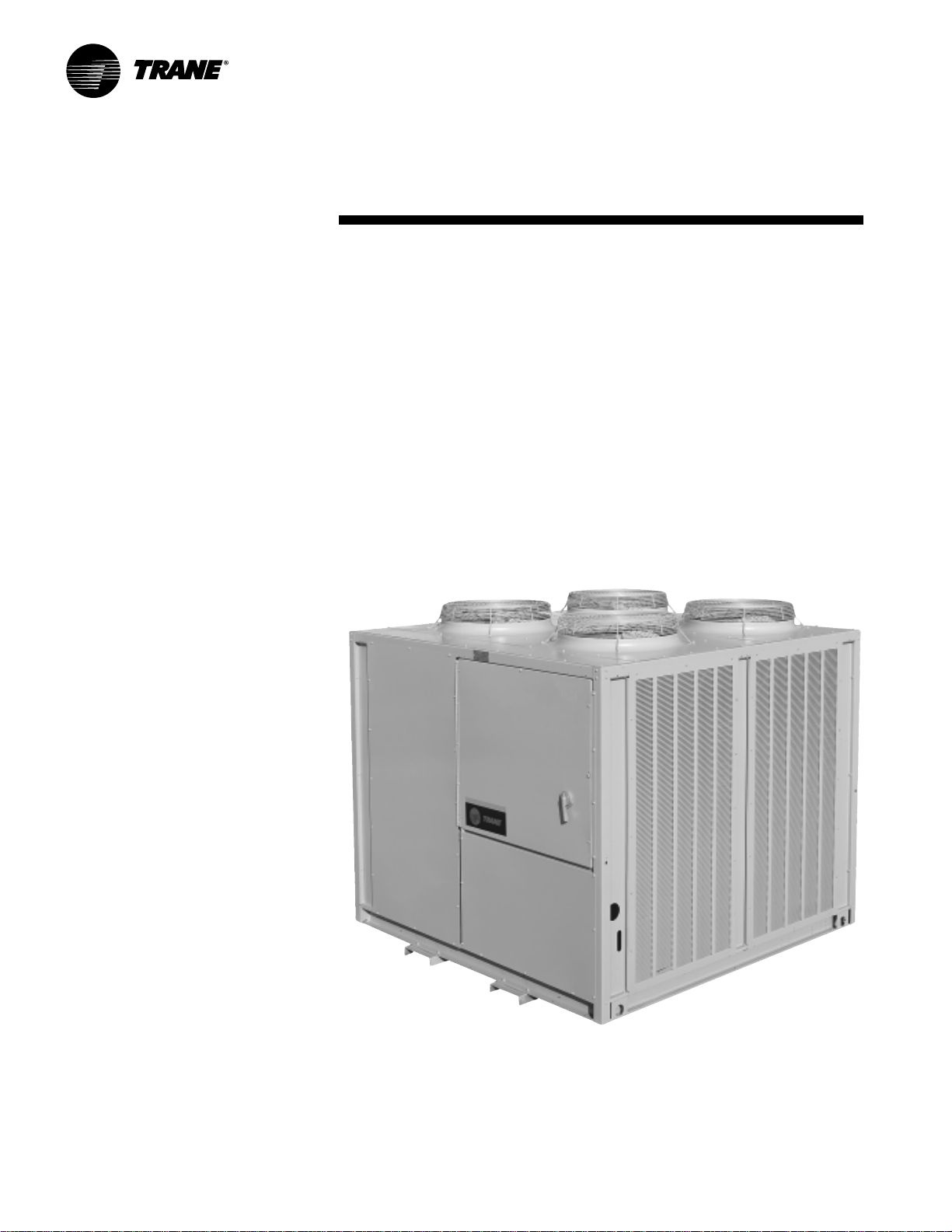
Air-Cooled Condensers
Built for Every Need
Trane has the r ight condenser...If you are
designing a new system or replacing an
existing air -cooled condenser , T rane can
satisfy virtually any application need.
Whether coupled with an industrial
compressor, a single zone commercial
self-contained unit, compressor chiller
or a Cold Generator
the right air -cooled condenser for the
job. When teamed with any one of a
®
chiller , T rane has
wide range of compressor -evaporator
combinations, Trane air-cooled
condensers, available in 20 to 120 tons,
are ideal for multistory office buildings,
hotels, schools, municipal and
industrial facilities.
©American Standard Inc. 2001
ACDS-PRC001-EN
Page 3
Contents
Introduction
Featur es and Benefits
Application Considerations
Selection Procedur e
Model Number Description
General Data
P erformance Data
Performance Adjustment Factors
Electric P o wer
Dimension and Weights
Mechanical Specifications
2
4
5
6
8
9
11
10
12
13
23
ACDS-PRC001-EN
3
Page 4

Features and Benefits
20 to 120 T on Units
T rane 20 to 120 ton air-cooled
condensers have an operating range of
40 F to 115 F, with a low ambient option
down to 0 F.
The control panel is factory-installed
and wired to prevent potential damage
and to provide weathertight protection.
The control panel contains:
• fan motor contactors.
• fan cycling controls.
• terminal point connection for
compressor interlock.
• 115-volt control power transformer .
These standard features reduce
installation costs and provide easy
interface with control logic.
Application
All Trane air-cooled condenser coils are
tube-in-sheet construction with copper
tubing mechanically bonded to
configurated aluminum fins. 20 to 30
ton condensers are single circuit; 40 to
120 ton units are dual circuited; all
feature integral subcooling.
Copper coils are optional.
Durable Construction
T rane 20 to 120 ton condensers are
built for long life. The unit frame is
constructed of 14 gauge g alvanized
steel. Louvered panels provide
excellent coil protection while
enhancing unit appearance and
strength. The unit surface is
phosphatized and finished with T rane
Slate Grey air -dry paint. This air drypaint finish exceeds 500 consecutive
hour salt spray resistance in
accordance with AS TM B117.
Considerations
Certain application constraints should be
considered when sizing, selecting, and
installing air -cooled condensers. Unit
and system reliability depends on
properly and completely acknowledging
these considerations. Consult your local
T rane sales engineer if your application
varies from these guidelines.
Setting the Unit
A base or foundation is not required if
the selected unit location is level and
strong enough to support the operating
weight. Refer to the Weights section for
the weight of individual units.
Isolation and Sound Emission
The most effective method of noise
isolation is proper unit location. Units
should be placed away from noise
sensitive areas. Structurally transmitted
noise can be reduced with the use of
spring isolators and they are
recommended for acoustically sensitive
applications. Flexible electrical conduit,
for maximum isolation effectiveness, will
reduce sound transmitted through
electrical conduit.
State and local codes on sound
emissions should always be
considered. Since the environment in
which a sound source is located affects
sound pressure, unit placement must
be carefully evaluated.
Servicing
Recommended minimum space
envelopes for servicing are located in
the Dimensional Data section and
serve as guidelines for providing
adequate clearance. The minimum
space envelopes also allow for control
panel door swing and routine
maintenance requirements.
ACDS-PRC001-EN4
Page 5
Application
Considerations
Unit Location
Unobstructed flow of condenser air is
essential to maintaining capacity and
operating efficiency . When determining
unit placement, careful consideration
must be given to assure a sufficient flow
of air across the condenser heat transfer
surface. Two detrimental conditions are
possible and must be avoided: Warm air
recirculation and coil starvation.
Warm air recirculation occurs when
discharge air from the condenser fans is
recycled back at the condenser coil inlet.
Coil starvation occurs when free airflow
to the condenser is restricted.
Both warm air recirculation and coil
starvation cause reductions in unit
efficiency and capacity because of the
higher head pressures associated with
them. In more severe cases, nuisance
unit shutdowns will result from
excessive head pressures.
Cross winds, those perpendicular to the
condenser, tend to aid ef ficient operation
in warmer ambient conditions.
However, they tend to be detrimental to
operation in lower ambients or when hot
gas bypass is used due to the
accompanying loss of adequate head
pressure. As a result, it is advisable to
protect air -cooled condensers from
continuous direct winds exceeding 10
miles per hour.
Debris, trash, supplies, etc., should not
be allowed to accumulate in the vicinity
of the air -cooled condenser. Supply air
movement may draw debris into the
condenser coil, blocking spaces between
coil fins and causing coil starvation.
Special consideration should be given to
low ambient units. Condenser coils and
fan discharge must be kept free of snow
or other obstructions to permit
adequate airflow for satisfactory unit
operation.
Clearance
V ertical condenser air discharge must be
unobstructed. While it is dif ficult to
predict the degree of warm air
recirculation, a unit installed with a
ceiling or other obstruction above it will
lose capacity and the maximum ambient
operation will be reduced. Nuisance
high head pressure tripouts may also
occur.
The inlet to the coil must also be
unobstructed. A unit installed closer
than the minimum recommended
distance to a wall or other vertical riser
may experience a combination of coil
starvation and warm air recirculation,
resulting in unit capacity and efficiency
reductions, as well as possible excessive
head pressures. The recommended
lateral distances are listed in the
Dimensional Data section.
V oltag e
Nominal voltage is the nameplate rating
voltage. The actual range of line voltages
at which the equipment can
satisfactorily operate is given below:
Nominal Voltage
Voltage Utilization Range
200/220 180-220 or 208-254
460 416-508
575 520-635
200/230-volt units ship from the factory
set for operation in the 180 through 220volt range. By c hanging leads on unit
transformers, the unit will operate in the
208 through 254-volt range.
Effects of Altitude
The tables in the Performance Data
section are for use at sea level. At
elevations substantially above sea level,
the decreased air density will decrease
condenser capacity. R efer to the
Performance Adjustment F actors section
to correct performance at other altitudes.
Ambient Limitations
T rane condensers are designed for yeararound applications in ambients from 0 F
through 115 F. For operation below 0 F or
above 115 F, contact the local Trane sales
office.
Start-up and operation of Trane
condensers at lower ambient
temperatures require that sufficient head
pressure be maintained for proper
operation. Minimum operating ambient
temperatures for standard unit
selections and units with hot gas bypass
are shown in the General Data section.
These temperatures are based on still
conditions (winds not exceeding five
mph.) Greater wind velocities will result
in a drop in head pressure, therefore,
increasing the minimum starting and
operating ambient temperatures.
Units with the low ambient option are
capable of starting and operating in
ambients down to 0 F, 10 F with hot gas
bypass. Optional low ambient units use
a condenser fan damper arrangement
that controls condenser capacity by
modulating in response to head
pressure.
Maximum cataloged ambient
temperature operation of a standard
condenser is 115 F. Operation at design
ambients above 115 F can result in
excessive head pressures. For operation
above 115 F, contact the local Trane sales
office.
5ACDS-PRC001-EN
Page 6
Selection
Pr ocedures
When selecting a combination of
equipment, it becomes necessary to
match the compressor and condenser
performance. The following procedure
should be used in determining the
correct condenser .
First:
Determine the total cooling load and the
evaporator sst and compressor required.
Example:
Given – Total cooling load = 96 tons
The compressor was selected from
COM-DS-1 catalog according to the sst
and maximum acceptable condensing
temperature for adequate compressor
capacity.
a
Plot at least two gross compressor
capacities (less subcooling) at the design
suction temperature and different
condensing temperatures. (subcooling
factor is .047% per deg. F subcooling, 16
F for CU AB-D10E)
Example:
(From COM-DS-1)
CUAB-D1 0E Compressor at 45 F sst.
With:
1 15 F condensing temperature = 113.5
tons divided by 1.075 subcooling factor =
105.6 tons.
With:
125 F condensing temperature = 105.1
tons divided by 1.075 subcooling factor =
97.8 tons
b
Plot two gross condenser heat rejection
points on chart PD-1 divided by the
compressor N factor (Table PD-1 to PD-3)
at different condensing temperatures.
Example: Anticipating 100 ton
condenser to meet design load of 96
tons.
Cond.
Temp ITD (MBh) = Tons ÷ N F actor = Tons
11 5 at 20 = 830 = 69.2 ÷ 1.25* = 55.4
125 at 30 = 1285 = 107.1 ÷ 1.30* = 82.3
– Ambient temp = 95 F
– Evaporator sst = 45 F
– Compressor – CUAB-D1 0E
Gross Heat
of Rejection
c
T ransfer the results from the compressor
and condenser plots to Chart SP-1 and do
the following. Draw a line through the
two points representing gross heat
compressor capacities less subcooling
(1 05.6 and 82.3). Draw a line through the
two points representing condenser gross
heat of rejection (55.4 and 82.3).
d
At the point of intersection of the
compressor and condenser lines draw
dashed lines to the left and bottom
margins of Chart SP-1. The end points of
these lines will show a resultant gross
condenser capacity of 93.8 tons at 129.4 F
condensing temperature.
e
From c hart PD-2 calculate the percent
increase in capacity due to subcooling.
Example:
At 95 F ambient and 129.4 F condensing
temperature there is a 10.1% increase in
capacity due to subcooling. This yields a
system net capacity of 93.8 tons x 110%
= 1 03.2 tons.
f
If necessary use the values in Table PD-4
to adjust the system capacity for altitude.
g
Compare this result with the design
capacity and condensing temperature.
The required cooling load is 96 tons,
therefore, the CAUC-D1 0 is the proper
selection.
Repeat the process steps B through G as
necessary to achieve the most economic
condenser selection.
*N factor corrected from Table PD-2
sst – saturated suction temperature
F – degree Fahrenheit
N – compressor factor
ITD – initial temperature difference
ACDS-PRC001-EN6
Page 7
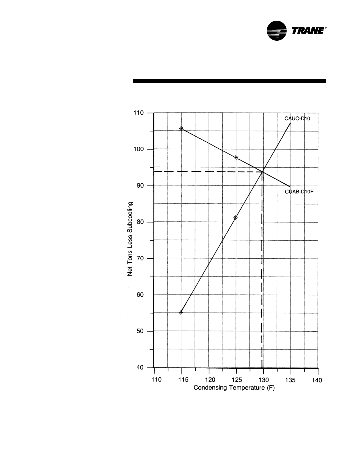
Selection Example
Chart SP-1 — Selection Example
7ACDS-PRC001-EN
Page 8
Model Number Description
20 To 60 Ton Model Nomenclature
Digit 1 — Unit Type
C = Condenser
Digit 2 — Condenser
A = Air-Cooled
Digit 3 — Airflow
U = Upflow
C A U C C20 4 1 * 0 3 H 0
1 2 3 4 5,6,7 8 9 10 11 12 13 14
Digit 4 — Development Sequence
C = Third
Digit s 5,6,7 — Nominal Capacity
C20 = 20 Tons C40 = 40 Tons
C25 = 25 Tons C50 = 50 Tons
C30 = 30 Tons C60 = 60 Tons
Digit 8 — Power Supply
G = 200/230/60/3 XL
4 = 460/60/3 XL
5 = 575/60/3 XL
Digit 9 — Condenser Circuit
1 = Single (20-30 Ton)
2 = Dual (40-60 Ton)
Digit 10 — Design Sequence
* = Factory Assigned
Digit 1 1 — Ambient Control
0 = Standard
1=0 F
Digit 12 — Agency Approval
0 = None
3 = UL/CSA
Digits 13, 14 — Miscellaneous
H = Copper Fins
1 = Spring Isolators
2 = Rubber Isolators
1
80 T o 120 Ton Model Nomenclature
C A U C C80 4 2 A 0 3 H 0
1 2 3 4 5,6,7 8 9 10 11 12 13 14
Digit 1 — Unit Type
C = Condenser
Digit 2 — Condenser
A = Air-Cooled
Digit 3 — Airflow
U = Upflow
1. The service digit for each model number contains 14 digits; all 14 digits must be referenced.
Digit 4 — Development Sequence
C = Third
Digits 5,6,7 — Nominal Capacity
C80 = 80 Tons
D10 = 100 Tons
D12 = 120 Tons
Digit 8 — Power Supply
F = 230/60/3
4 = 460/60/3
5 = 575/60/3
E = 200/60/3
Digit 9 — Condenser Circuit
2 = Dual Circuit
Digit 10 — Design Sequence
A = First
1
Digit 1 1 — Ambient Control
0 = Standard
1 = 0 F
Digit 12 — Agency Approval
0 = None
2 = CSA
3 = UL/CSA
Digits 13, 14 — Miscellaneous
H = Copper Fins
1 = Spring Isolators
ACDS-PRC001-EN8
Page 9

General Data
Table GD-1 — General Data
20 T on 25 T on 30 T on 40 T on 50 T on 60 T on 80 T on 100 T on 120 T on
Model Number CAUC-C20 CAUC-C25 CAUC-C30 CAUC-C40 CAUC-C50 CAUC-C60 CAUC-C80 CAUC-D10 CAUC-D12
Gross Heat Rejection (MBh)
Condenser Fan Data
Number/Size/T ype 2/26”/Prop 3/26”/Prop 3/26”/Prop 4/26”/Prop 6/26”/Prop 6/26”/Prop 8/26”/Prop 12/26”/Prop 12/26”/P rop
Fan Drive Direct Direct Direct Direct Direct Direct Direct Direct Direct
No. of Motors/Hp (Each) 2/1.0 3/1.0 3/1.0 4/1.0 6/1.0 6/1.0 8/1 .0 12/1.0 12/1 .0
Nominal Cfm 12,400 16,700 19,000 24,800 33,400 38,000 49,600 66,800 76,000
Condenser Coil Data
No./Size (In.) 1/63x71 1/71x71 1/45x71 2/65x70 2/51x96 2/66x90 4/65x70 4/51x96 4/66x90
Face Area (Sq. Ft.) 31.0 35.0 46.1 63.2 67.1 88.0 126.4 136.0 165.0
Rows/Fins Per Ft. 3/168 3/156 3/168 3/168 3/156 3/168 3/168 3/156 3/168
General Data
No. Refrigerant Circuits 1 1 1222 222
Operating Charge
Condenser Storage Capacity367 76 96 136 142 184 272 284 368
Ambient Temperature Operating Range
Standard Ambient (F) 40-115 40-115 40-11 5 40-115 40-1 1 5 40-115 40-1 15 40-115 40-1 15
Low Ambient Option (F) 0-115 0-115 0-115 0-115 0-115 0-1 15 0-115 0-11 5 0-1 15
Notes:
1. Gross Heat Rejection is at a 30 F ITD (Intial Temperature Difference) between condensing temperature and ambient air entering condenser (includes the effect of
subcooling).
2. Operating charge is for entire unit.
3. At conditions of 95 F ambient, condenser is 95 percent full.
2
(Lbs of R-22) 25 28 37 52 56 74 104 112 148
1
301 373 455 614 712 888 1244 1425 181 9
1/49x71
9ACDS-PRC001-EN
Page 10

P erformance Adjustment Factors
Chart PD-2— Compressor-Condenser Capacity Incr ease Due T o Subcooling (R-22)
Table PD-1 –- N Factor –- Semihermetic Compr essors
Cond.
Temp. 30 35 40 45 50
110 1 .34 1.32 1.29 1.27 1.25
115 1.36 1.34 1.31 1.29 1.27
120 1.40 1 .37 1.34 1.32 1.30
125 1.43 1 .40 1.37 1.34 1.32
130 1.48 1 .44 1.40 1.38 1.35
135 1.52 1 .48 1.44 1.41 1.38
140 1.58 1 .54 1.49 1.45 1.42
145 1.65 1 .59 1.54 1.49 1.46
Note:
1. In order to determine N factor for CUAB units, find proper factor corresponding with the proper
suction and condensing temperature from Table 9-1. This factor should be adjusted by adding or
subtracting the correction value from Table 9-2.
Saturated Suction Temperature (F)
Table PD-2–- N Factor –- Open Compressors
Cond.
Temp. 30 35 40 45 50
110 1.245 1 .225 1 .21 5 1.195 1.175
115 1 .260 1.240 1.230 1.210 1.190
120 1.275 1.255 1.245 1.225 1.205
125 1.290 1.270 1.260 1.240 1.220
130 1.305 1.285 1.275 1.255 1.235
135 1.320 1.300 1.290 1.270 1.250
140 1 .335 1.315 1.305 1.285 1.265
Saturated Suction Temperature (F)
Table PD-3 –- Altit ude Corr ection Multiplier F or Cooling Capacity –- Air -Cooled Condenser
Altitude (Ft) 2,000 4,000 6,000 8,000 10,000
Correction Multiplier 0.977 0.949 0.917 0.881 0.843
Table PD-4 –- N Factor Corr ection –- Compressor
Compressor Correction Factor
CUAB-015M + 0.02
020M –––
025M – 0.01
030M + 0.01
040R – 0.02
050R – 0.04
060R – 0.04
075E – 0.02
100E – 0.04
ACDS-PRC001-EN10
Page 11

P erformance
Data
Chart PD-1 — Condenser Heat Rejection (R-22), 20-120 Ton
11ACDS-PRC001-EN
Page 12

Electrical Data
Table ED-1 — Electrical Data
Unit Characteristics Condenser Fan Motor
Nominal Electrical Voltage Ampacity Size No./HP (Ea.) (Ea.) (Ea.)
T ons Model No. Characteristics Range (3),(5) (2),(5) (1) (1) (1) (1),(4)
20 CAUC-C204 460/60/3 416-508 4.1 15 2/1 .0 1 .8 9.0 0.9
25 CAUC-C254 460/60/3 416-508 5.9 15 3/1.0 1.8 9.0 0.9
30 CAUC-C304 460/60/3 416-508 5.9 15 3/1.0 1.8 9.0 0.9
40 CAUC-C404 460/60/3 416-508 7.7 15 4/1.0 1.8 9.0 0.9
50 CAUC-C504 460/60/3 416-508 11.3 15 6/1.0 1.8 9.0 0.9
60 CAUC-C604 460/60/3 416-508 11.3 15 6/1.0 1.8 9.0 0.9
80 CAUC-C80F 230/60/3 208-254 34 40 8/1.0 4.1 20.7 0.9
100 CAUC-D10F 230/60/3 208-254 50 60 12/1.0 4.1 20.7 0.9
120 CAUC-D12F 230/60/3 208-254 50 60 12/1.01 4.1 20.7 0.9
Notes:
1. Electric information is for each individual motor.
2. Maximum fuse size is permitted by NEC 440-22 is 300 percent of one motor RLA plus the RLA of the remaining motors.
3. Minimum circuit ampacity equals 125 percent of the RLA of one motor plus the RLA of the remaining motors.
4. All Kw values taken at conditions of 45 F saturated suction temperature at the compressor and 95 F ambient.
5. Local codes may take precedence.
CAUC-C20G 200-230/60/3 180-220/208-254 9.2 15 2/1 .0 4.1 20.7 0.9
CAUC-C205 575/60/3 520-635 3.2 15 2/1.0 1.4 7.2 0.9
CAUC-C25G 200-230/60/3 180-220/208-254 13.3 20 3/1.0 4.1 20.7 0.9
CAUC-C255 575/60/3 520-635 4.6 15 3/1.0 1.4 7.2 0.9
CAUC-C30G 200-230/60/3 180-220/208-254 13.3 20 3/1 .0 4.1 20.7 0.9
CAUC-C305 575/60/3 520-635 4.6 15 3/1.0 1.4 7.2 0.9
CAUC-C40G 200-230/60/3 180-220/208-254 17.4 20 4/1.0 4.1 20.7 0.9
CAUC-C405 575/60/3 520-635 6.0 15 4/1.0 1.4 7.2 0.9
CAUC-C50G 200-230/60/3 180-220/208-254 25.6 30 6/1.0 4.1 20.7 0.9
CAUC-C505 575/60/3 520-635 8.8 15 6/1.0 1.4 7.2 0.9
CAUC-C60G 200-230/60/3 180-220/208-254 25.6 30 6/1.0 4.1 20.7 0.9
CAUC-C605 575/60/3 520-635 8.8 15 6/1.0 1.4 7.2 0.9
CAUC-C80E 200/60/3 180-220 34 40 8/1.0 4.1 20.7 0.9
CAUC-C804 460/60/3 416-508 15 20 8/1.0 1.8 9.0 0.9
CAUC-C805 575/60/3 520-635 12 15 8/1.0 1.4 7.2 0.9
CAUC-D10E 200/60/3 180-220 50 60 12/1.0 4.1 20.7 0.9
CAUC-D104 460/60/3 416-508 22 25 12/1.0 1.8 9.0 0.9
CAUC-D105 575/60/3 520-635 17 20 12/1.0 1.4 7.2 0.9
CAUC-D12E 200/60/3 180-220 50 60 12/1.0 4.1 20.7 0.9
CAUC-D124 460/60/3 416-508 22 25 12/1.0 1.8 9.0 0.9
CAUC-D125 575/60/3 520-635 17 20 12/1.0 1.4 7.2 0.9
Allowable Circuit Fuse FLA LRA KW
Minimum Maximum
ACDS-PRC001-EN12
Page 13

Dimensional (20 Ton)
Data
Figure DD-1 — CAUC-C20 Unit Dimensions, Recommended Clearances, Mounting Locations, Electr ic and Refr ig erant Connection Siz es and Locations
13ACDS-PRC001-EN
Page 14

Dimensional (25 Ton)
Data
Figure DD-2 — CAUC-C25 Unit Dimensions, Recommended Clearances, Mounting Locations, Electric and Refr ig er ant Connection Sizes and Locations
ACDS-PRC001-EN14
Page 15

Dimensional (30 Ton)
Data
Figure DD-3 — CAUC-C30 Unit Dimensions, Recommended Clearances, Mounting Locations, Electr ic and Refrig er ant Connection Sizes and Locations
15ACDS-PRC001-EN
Page 16

Dimensional (40 Ton)
Data
Figure DD-4 — CAUC-C40 Unit Dimensions, Recommended Clearances, Mounting Locations, Electric and Refrigerant Connection Sizes and Locations
ACDS-PRC001-EN16
Page 17

Dimensional (50 Ton)
Data
Figure DD-5 — CAUC-C50 Unit Dimensions, Recommended Clearances, Mounting Locations, Electr ic and Refrig er ant Connection Sizes and Locations
17ACDS-PRC001-EN
Page 18
Dimensional (60 Ton)
Data
Figure DD-6 — CAUC-C60 Unit Dimensions, Recommended Clearances, Mounting Locations, Electric and Refr ig er ant Connection Sizes and Locations
ACDS-PRC001-EN18
Page 19

Dimensional (80 Ton)
Data
Figure DD-7 — CAUC-C80 Unit Dimensions, Recommended Clearances, Mounting Locations, Electric and Refriger ant Connection Sizes and Locations
NOTES:
1. HOT GAS DISCHARGE AND LIQUID LINE CONNECTION LOCATIONS
SHOWN IN THE FRONT VIEW DO NOT REPRESENT HOLES IN THE UNIT PANEL.
ACCESS TO THESE CONNECTIONS ARE PROVIDED BY THE CUSTOMERS.
2. DIMENSIONAL TOLERANCE +/- 1/8”.
19ACDS-PRC001-EN
Page 20

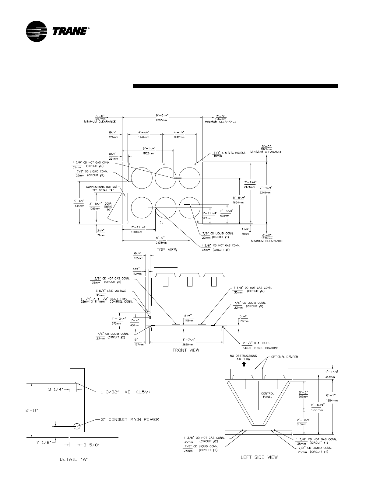
Dimensional (1 00 Ton)
Data
Figure DD-9 — CAUC-C100 Unit Dimensions, Recommended Clear ances, Mounting Locations, Electric and Refr ig er ant Connection Sizes and Locations
ACDS-PRC001-EN20
Page 21

Dimensional (120 Ton)
Data
Figure DD-1 0 — CAUC-C120 Unit Dimensions, Recommended Clearances, Mounting Locations, Electr ic and Refr ige rant Connection Sizes and Locations
NOTES:
1. HOT GAS DISCHARGE AND LIQUID LINE CONNECTION LOCATIONS
SHOWN IN THE FRONT VIEW DO NOT REPRESENT HOLES IN THE UNIT PANEL.
ACCESS TO THESE CONNECTIONS ARE PROVIDED BY THE CUSTOMERS.
2. DIMENSIONAL TOLERANCE +/- 1/8”.
21ACDS-PRC001-EN
Page 22

Weights
Figure W -1 — 20-30 Tons
Figure W -2 — 40-60 Tons
Top View (Mounting Locations)
T able W-1 — 20 to 60 Ton Weights (Lbs./Kg.)
Nominal Model Weight Loc. 1 Loc. 2 Loc. 3 Loc. 4 Loc. 5 Loc. 6
Tons Number AL CU AL CU AL CU AL CU AL CU AL CU AL CU
20 CAUC-C20 Lb. 1146 1348 320 371 326 365 248 306 252 301 –– –– –– ––
25 CAUC-C25 Lb. 1190 1394 329 378 337 381 259 315 265 319 –– –– –– ––
30 CAUC-C30 Lb. 1302 1585 353 414 371 444 282 355 296 381 –– –– –– ––
40 CAUC-C40 Lb. 2048 2366 363 406 347 392 349 404 334 389 335 401 320 387
50 CAUC-C50 Lb. 2280 2664 407 464 392 449 387 453 373 438 367 441 354 427
60 CAUC-C60 Lb. 2465 3010 433 515 420 505 417 511 405 501 401 507 389 497
Operating Weight On Isolator At Mounting Locations
Kg. 519.8 611.5 145.2 168.3 147.9 165.6 112.5 138.8 114.3 136.5
Kg. 539.8 632.3 149.2 171.5 152.9 172.8 117.5 142.9 120.2 144.7
Kg. 590.6 719.0 160.1 187.8 168.3 201.4 127.9 161.0 134.3 172.8
Kg. 929.0 1073.2 164.7 184.2 157.4 177.8 158.3 183.3 151.5 176.5 152.0 181.9 145.2 175.5
Kg. 1034.2 1208.4 184.6 210.5 177.8 203.7 175.5 205.5 169.2 198.7 166.5 200.0 160.6 193.7
Kg. 1118.1 1365.3 196.4 233.6 190.5 229.1 189.2 231.8 183.7 227.3 181.9 230.0 176.5 225.4
Figure W -3 — 80-120 Tons
Top View (Mounting Locations)
T able W-2 — 80 to 120 Ton Weights (Lbs./Kg.)
Nominal Model Coil Operating Weight On Isolator At Mounting Points
Tons Number Fin Weight Loc. 1 Loc. 2 Loc. 3 Loc. 4 Loc. 5 Loc. 6 Loc.7 Loc.8
80 CAUC-C80 Kg. 1830.7 233.2 216.8 236.8 220.0 237.7 220.9 241.3 224.1
100 CAUC-D10 Kg. 2227.6 286.2 272.2 285.8 271.3 285.3 271.3 284.9 270.8
120 CAUC-D12 Kg. 2482.1 316.6 302.1 317.5 303.0 317.5 303.0 318.4 303.9
AL Lb. 4036 514 478 522 485 524 487 532 494
CU Lb. 4542 603 571 600 569 600 568 597 566
Kg. 2060.3 273.5 259.0 272.2 258.1 272.2 257.6 270.8 256.7
AL Lb. 4911 631 600 630 598 629 598 628 597
CU Lb. 5371 586 549 597 560 600 562 611 572
Kg. 2436.3 265.8 249.0 270.8 254.0 272.2 254.9 277.1 259.5
AL Lb. 5472 698 666 700 668 700 668 702 670
CU Lb. 5971 774 742 779 747 780 748 786 753
Kg. 2708.4 351.1 336.6 353.4 338.8 353.8 339.3 356.5 341.6
ACDS-PRC001-EN22
Page 23

Mec hanical
Specifications
General
Factory-assembled and wired air cooled
condensing unit. The unit frame is
constructed of 14 gauge welded
galvanized steel. P anels and access
doors are 14 or 16 gauge galvaniz ed
steel. Unit surface is phosphatized and
finished with Trane Slate Gray air-dry
paint. This paint finish exceeds ASTMB117 500 hour continuous salt spray test.
The unit coils are protected with steel
louvered panels. These panels add
strength to the cabinet and an
aesthetically pleasing appearance to the
unit.
Refriger ation Circuits and Contr ol
The 20 to 30 ton units are single circuit.
The 40 to 120 ton units are dual circuited.
All the necessary controls to run the unit
fans are provided. The control panel
contains fan motor contactors, terminal
point connection for compressor
interlock and 115 volt control power
transformer. Standard units will operate
from 40 to 115 F. All units shipped with
factory installed liquid line service
valves.
Condenser Coils and Fans
Condenser coils have configurated
aluminum fins mechanically bonded to
copper tubing with integralsubcooler.
The coils are underwater burst/leak
tested at 450 psi. Direct
drive condenser fan motors have
permanently lubricated ball bearings
and thermal overload protection.
Low Ambient Operation
Standard ambient control allows
operation down to 40 F with cycling of
condenser fans. Optional low ambient
allows operation down to 0 F with
external damper assembly for head
pressure control. Refer to Options
section for details.
Options
Low Ambient Control
Low ambient allows operation down to
0 F through the use of fan cycling and
head pressure control dampers. The
control consists of a heavy gauge
damper assembly, R-22 operator , tubing
and grommet. All components are
factory-mounted for both production
and Pac ked Stoc k Plus units. Lo w
ambient control must be ordered when
the air -cooled condenser is matched
with a CCKC heat recovery chiller.
Copper Finned Condenser Coil
Copper fins are mechanically bonded to
copper tubes for use in corrosive
atmospheres. Nominal unit capacity
remains the same.
Spring Isolation Pa ck age
Spring isolators reduce transmission of
noise and vibration to building structure,
equipment, and adjacent spaces.
Isolators consist of a cast, spring loaded,
telescoping housing as the isolation
medium. Mountings include built-in
leveling bolts, resilient inserts that act as
centering guides, and ribbed neoprene
acoustical pads bonded to the bottom of
the isolator. The kit includes instructions
for field installation.
Neoprene-in-shear Isolation P ack age
Neoprene isolators reduce transmission
of noise and vibration to building
structure, equipment, and adjacent
spaces. Isolators have a steel plate and
base completely imbedded in neoprene.
Mountings have a 1/4-inch deflection.
The kit includes instructions for field
installation. A vailable on 20 to 60-ton
units only.
23ACDS-PRC001-EN
Page 24

The T rane Company
Unitary Products Group
2701 Wilma Rudolph Blvd.
Clarksville, TN 37040
www.trane.com
An American Standard Company
Literature Order Number ACDS-PRC001-EN
File Number PL-RF -A CDS-PRC0001-EN-04-200 1
Supersedes ACDS-DS-1 07/00
Stocking Location Inland-LaCrosse
Since The Trane Company has a policy of continuous product and product data improvement, it reserves the
right to change design and specifications without notice.
 Loading...