

TRANE Belt Maintenance Manual
Maintenance
Fan Belt Adjustment—Belt Drive
Units
WARNI NG
Rotating Components!
During installation, testing, servicing and
troubleshooting of this product it may be necessary to
measure the speed of rotating components. Have a
qualified or licensed service individual who has been
properly trained in handling exposed rotating
components, perform these tasks. Failure to follow all
safety precautions when exposed to rotating
components could result in death or serious injury.
The fan belts must be inspected periodically to assure
proper unit operation.
Replacement is necessary if the belts appear frayed or
worn. Units with dual belts require a matched set of belts
to ensure equal belt length.
When removing or installing the new belts, do not stretch
them over the sheaves. Loosen the belts using the belt
tension adjustment bolts on the motor mounting base.
Once the new belts are installed, using a Browning or
Gates tension gauge (or equivalent) illustrated in
Figure 31; adjust the belt tension as follows:
1. To determine the appropriate belt deflection:
a. Measure the center-to-center shaft distance (in
inches) between the fan and motor sheaves.
b. Divide the distance measured in Step 1a by 64; the
resulting value represents the amount of belt
deflection that corresponds to the proper belt
tension.
2. Set the large O-ring on the belt tension gauge at the
deflection value determined in Step 1b.
3. Set the small O-ring at zero on the force scale of the
gauge plunger.
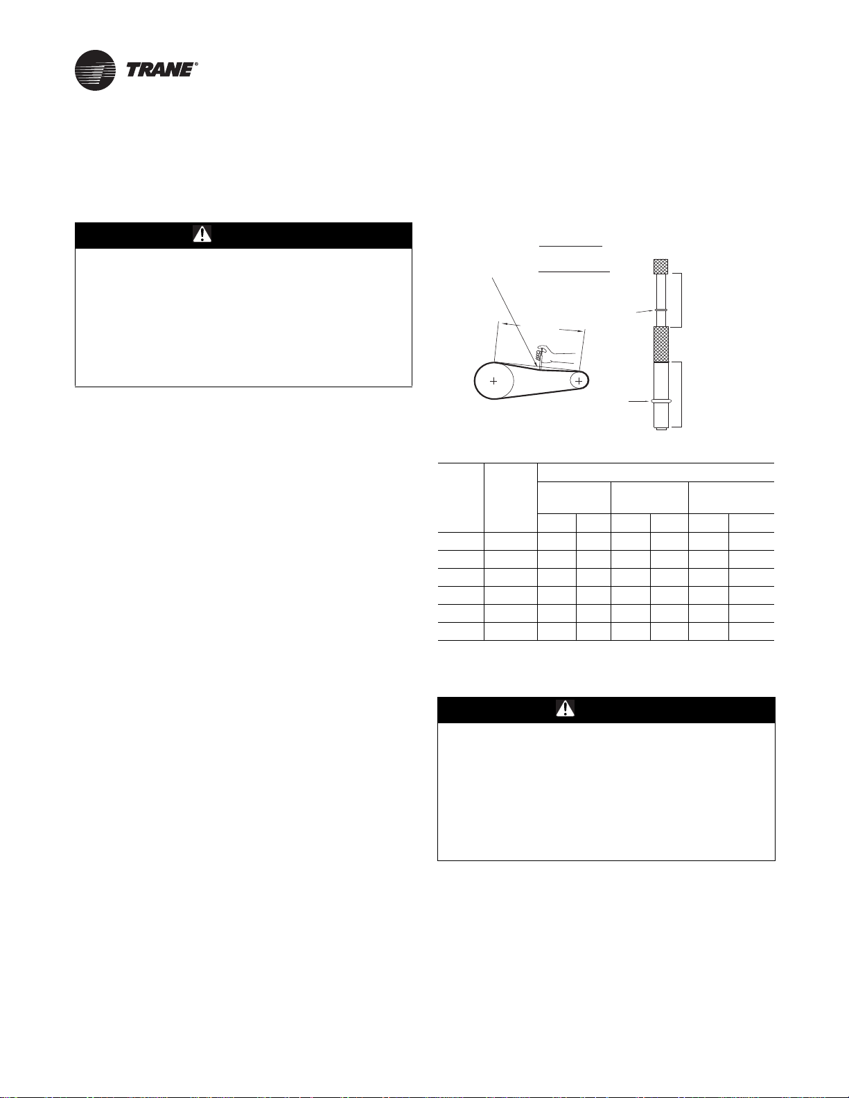
4. Place the large end of the gauge at the center of the belt
span; then depress the gauge plunger until the large
O-ring is even with the top of the next belt or even with
a straightedge placed across the fan and motor
sheaves. Refer to Figure 9.
5. Remove the belt tension gauge. The small O-ring now
indicates a number other than zero on the plunger’s
force scale. This number represents the force (in
pounds) required to give the needed deflection.
6. Compare the “force” scale reading (Step 5) with the
appropriate “force” value listed in Ta b le 10 . If the
“force” reading is outside the range, readjust the belt
tension.
Note: Actual belt deflection “force” must not exceed the
maximum “force” value shown in Ta b le 10 .
7. Recheck the belt tension at least twice during the first
2 to 3 days of operation. Belt tension may decrease
until the new belts are “run in”.
Figure 31. Belt tension gauge
Deflection =
Deflection =
Belt Span (in)
64
Belt Span (mm)
152
Belt
Span
Small
O-Ring
Large
O-Ring
Force Scale
Span Scale
Table 10. Belt tension measurement and deflection
Deflection Force (Lbs)
Belts
Cross-
Section
Small
P.D.
Range
3.0–3.6 3 4 1/2 3 7/8 5 1/2 3 1/4 4
A 3.8–4.8 3 1/2 5 4 1/2 6 1/4 3 3/4 4 3/4
5.0–7.0 4 5 1/2 5 6 7/8 4 1/4 5 1/4
3.4–4.2 4 5 1/2 5 3/4 8 4 1/2 5 1/2
B 4.4–5.6 5 1/8 7 1/8 6 1/2 9 1/8 5 3/4 7 1/4
5.8–8.8 6 3/8 8 3/4 7 3/8 10 1/8 7 8 3/4
Super
Gripbelts Gripnotch
Min. Max. Min. Max. Min. Max
Steel Cable
Gripbelts
Monthly Maintenance
WARNI NG
Rotating Components!
During installation, testing, servicing and
troubleshooting of this product it may be necessary to
measure the speed of rotating components. Have a
qualified or licensed service individual who has been
properly trained in handling exposed rotating
components, perform these tasks. Failure to follow all
safety precautions when exposed to rotating
components could result in death or serious injury.
Before completing the following checks, turn the unit OFF
and lock the main power disconnect switch open.
Filters
Inspect the return air filters. Clean or replace them if
necessary. Refer to the unit Service Facts for filter
information.
34 RT-SVX38C-EN
Maintenance
Condensate Overflow Switch
During maintenance, the switch float (black ring) must be
checked to ensure free movement up and down.
Cooling Season
• Check the unit’s drain pans and condensate piping to
ensure that there are no blockages.
• Inspect the evaporator and condenser coils for dirt,
bent fins, etc. If the coils appear dirty, clean them
according to the instructions described in “Coil
Cleaning” later in this section.
• Manually rotate the condenser fan(s) to ensure free
movement and check motor bearings for wear. Verify
that all of the fan mounting hardware is tight.
• Inspect the F/A-R/A damper hinges and pins to ensure
that all moving parts are securely mounted. Keep the
blades clean as necessary.
• Verify that all damper linkages move freely; lubricate
with white grease, if necessary.
• Check supply fan motor bearings; repair or replace the
motor as necessary.
• Check the fan shaft bearings for wear. Replace the
bearings as necessary.
• Check the supply fan belt. If the belt is frayed or worn,
replace it. Refer to the “Fan Belt Adjustment” section
for belt replacement and adjustments.
• Verify that all wire terminal connections are tight.
• Remove any corrosion present on the exterior surfaces
of the unit and repaint these areas.
• Generally inspect the unit for unusual conditions (e.g.,
loose access panels, leaking piping connections, etc.)
• Make sure that all retaining screws are reinstalled in
the unit access panels once these checks are complete.
• With the unit running, check and record the ambient
temperature, compressor suction and discharge
pressures (each circuit), and superheat (each circuit).
• Record this data on an “operator’s maintenance log”
like the one shown in Table 11, p. 37. If the operating
pressures indicate a refrigerant shortage, measure the
system superheat. For guidelines, refer to the
“Compressor Start-Up” section.
Note: Do not release refrigerant to the atmosphere! If
adding or removing refrigerant is required, the
service technician must comply with all federal,
state and local laws.
Heating Season
• Inspect the unit’s air filters. If necessary, clean or
replace them.
• Check supply fan motor bearings; repair or replace the
motor as necessary.
• Inspect both the main unit control panel and heat
section control box for loose electrical components
and terminal connections, as well as damaged wire
insulation. Make any necessary repairs.
• Clean burner area; verify gas heat system operates
properly.
Coil Cleaning
Regular coil maintenance, including annual cleaning,
enhances the unit’s operating efficiency by minimizing:
• Compressor head pressure and amperage draw
• Evaporator water carryover
• Fan brake horsepower, due to increased static
pressure losses
• Airflow reduction
At least once each year, or more often if the unit is located
in a “dirty” environment, clean the evaporator and
condenser coils using the instructions outlined below. Be
sure to follow these instructions as closely as possible to
avoid damaging the coils.
Note: For units equipped with hail guards follow removal
procedure listed below.
Hail Guard Removal
• Unlatch hail guard.
• Pull the top of the hail guard outward until the fastener
studs are free of the retaining nuts.
• Lift the hail guard from the lower retaining bracket and
set aside.
To clean refrigerant coils, use a soft brush and a sprayer
(either a garden pump-up type or a high-pressure sprayer).
A high-quality detergent is also required; suggested
brands include SPREX A.C., OAKITE 161, OAKITE 166, and
COILO. If the detergent selected is strongly alkaline (ph
value exceeds 8.5), add an inhibitor.
WARNI NG
Hazardous Chemicals!
Coil cleaning agents can be either acidic or highly
alkaline. Handle chemical carefully. Proper handling
should include goggles or face shield, chemical
resistant gloves, boots, apron or suit as required. For
personal safety refer to the cleaning agent
manufacturer’s Materials Safety Data Sheet and follow
all recommended safe handling practices. Failure to
follow all safety instructions could result in death or
serious injury.
1. Remove enough panels from the unit to gain access to
the coil.
2. Protect all electrical devices such as motors and
controllers from any over spray.
3. Straighten any bent coil fins with a fin comb.
RT-SVX38C-EN 35
Maintenance
4. Mix the detergent with water according to the
manufacturer’s instructions. If desired, heat the
solution BUT DO NOT EXCEED 150°F maximum to
improve its cleansing capability.
WARNI NG
Hazardous Pressures!
Coils contain refrigerant under pressure. When cleaning
coils, maintain coil cleaning solution temperature under
150°F to avoid excessive pressure in the coil. Failure to
follow these safety precautions could result in coil
bursting, which could result in death or serious injury.
5. Pour the cleaning solution into the sprayer. If a
high-pressure sprayer is used:
a. Do not allow sprayer pressure to exceed 600 psi.
b. The minimum nozzle spray angle is 15 degrees.
c. Maintain a minimum clearance of 6" between the
sprayer nozzle and the coil.
d. Spray the solution perpendicular (at 90 degrees) to
the coil face.
6. Spray the leaving-airflow side of the coil first; then
spray the opposite side of the coil. Allow the cleaning
solution to stand on the coil for 5 minutes.
7. Rinse both sides of the coil with cool, clean water.
8. Inspect both sides of the coil; if it still appears to be
dirty, repeat Steps 6 and 7.
9. Reinstall all of the components and panels removed in
Step 1 and any protective covers installed in Step 2.
Note: For units equipped with hail guards follow
reinstallation procedure listed below.
Annual Maintenance
• Clean and repaint any corroded surface.
Hail Guard Reinstallation
1. To reinstall the hail guard, locate the bottom of the hail
guard in the lower bracket and secure it to the upper
unit bracket with the attached fasteners.
Note: Secure hail guard latches.
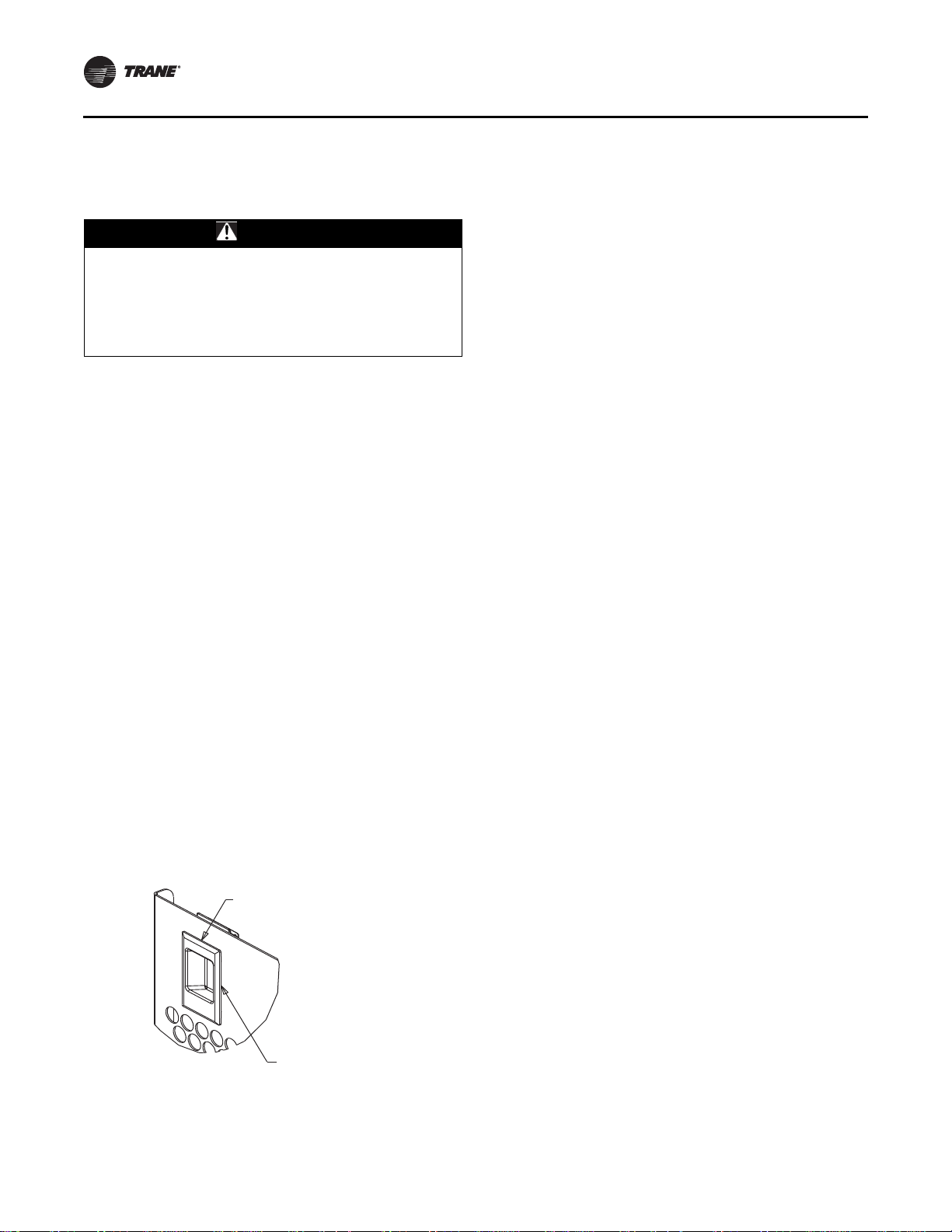
Figure 32. Slide latch
Slide Latch
Detail A
2. Restore the unit to its operational status and check
system operation.
36 RT-SVX38C-EN
Pull down to
disengage guard
 Loading...