

Page 1
Installation, Operation, and
Maintenance
Blower Coil Air Handler
Air Terminal Devices - 400 to 3000 cfm
Models BCHC and BCVC
“AO” and later design sequence
April 2008
BCXC-SVX01B-EN
Page 2

Warnings, Cautions and Notices
Warnings, Cautions and Notices. Note that warnings, cautions and notices appear at
appropriate intervals throughout this manual. Warnings are provide to alert installing contractors
to potential hazards that could result in personal injury or death. Cautions are designed to alert
personnel to hazardous situations that could result in personal injury, while notices indicate a
situation that may result in equipment or property-damage-only accidents.
Your personal safety and the proper operation of this machine depend upon the strict observance
of these precautions.
ATTENTION: Warnings, Cautions and Notices appear at appropriate sections throughout this
literature. Read these carefully.
WARN ING – Indicates a potentially hazardous situation which, if not avoided, could result in
death or serious injury.
CAUTION – Indicates a potentially hazardous situation which, if not avoided, could result in
minor or moderate injury. It could also be used to alert against unsafe practices.
NOTICE – Indicates a situation that could result in equipment or property-damage only accidents.
Important
Environmental Concerns!
Scientific research has shown that certain man-made chemicals can affect the earth's naturally
occurring stratospheric ozone layer when released to the atmosphere. In particular, several of the
identified chemicals that may affect the ozone layer are refrigerants that contain Chlorine, Fluorine
and Carbon (CFCs) and those containing Hydrogen, Chlorine, Fluorine and Carbon (HCFCs). Not all
refrigerants containing these compounds have the same potential impact to the environment.
Trane advocates the responsible handling of all refrigerants-including industry replacements for
CFCs such as HCFCs and HFCs.
Responsible Refrigerant Practices!
Trane believes that responsible refrigerant practices are important to the environment, our
customers, and the air conditioning industry. All technicians who handle refrigerants must be
certified. The Federal Clean Air Act (Section 608) sets forth the requirements for handling,
reclaiming, recovering and recycling of certain refrigerants and the equipment that is used in these
service procedures. In addition, some states or municipalities may have additional requirements
that must also be adhered to for responsible management of refrigerants. Know the applicable
laws and follow them.
WARNING
Refrigerant warning information!
System contains oil and refrigerant under high pressure. Recover refrigerant to relieve pressure
before opening the system. See unit nameplate for refrigerant type. Do not use non-approved
refrigerants, refrigerant substitutes, or refrigerant additives.
Failure to follow proper procedures or the use of non-approved refrigerants, refrigerant
substitutes, or refrigerant additives could result in death or serious injury or equipment damage.
© 2008 Trane All rights reserved BCXC-SVX01B-EN
Page 3

Warnings, Cautions and Notices
WARNING
Hazard of Explosion and Deadly Gases!
Never solder, braze or weld on refrigerant lines or any unit components that are above
atmospheric pressure or where refrigerant may be present. Always remove refrigerant by
following the guidelines established by the EPA Federal Clean Air Act or other state or local
codes as appropriate. After refrigerant removal, use dry nitrogen to bring system back to
atmospheric pressure before opening system for repairs. Mixtures of refrigerants and air under
pressure may become combustible in the presence of an ignition source leading to an explosion.
Excessive heat from soldering, brazing or welding with refrigerant vapors present can form
highly toxic gases and extremely corrosive acids. Failure to follow all proper safe refrigerant
handling practices could result in death or serious injury.
BCXC-SVX01B-EN 3
Page 4

Introduction
About This Manual
Use this manual for commercial blower coil models BCHC and BCVC. This is the second version
of this manual; this manual supercedes BCXB-SVX01A-EN. It provides specific installation,
operation, and maintenance instructions for “AO” and later design sequences.
For previous design sequence information, contact your local Trane representative.
Trademarks
Trane, the Trane logo, Frostat, Integrated Comfort, Rover, Tracer, and Tracer Summit are trademarks
of Trane in the United States and other countries. All trademarks referenced in this document are
the trademarks of their respective owners.
4 BCXC-SVX01B-EN
Page 5

Table of Contents
Model Number Description . . . . . . . . . . . . . . . . . . . . . . . . . . . . . . . . . . . . . . . . . . . . . . 7
General Information . . . . . . . . . . . . . . . . . . . . . . . . . . . . . . . . . . . . . . . . . . . . . . . . . . . . 9
Pre-Installation . . . . . . . . . . . . . . . . . . . . . . . . . . . . . . . . . . . . . . . . . . . . . . . . . . . . . . . . 11
Receiving and Handling . . . . . . . . . . . . . . . . . . . . . . . . . . . . . . . . . . . . . . . . . . . . 11
Pre-Installation Checklist . . . . . . . . . . . . . . . . . . . . . . . . . . . . . . . . . . . . . . . . . . . 14
Dimensions and Weights . . . . . . . . . . . . . . . . . . . . . . . . . . . . . . . . . . . . . . . . . . . . . . . 15
Jobsite Storage Recommendations . . . . . . . . . . . . . . . . . . . . . . . . . . . . . . 11
Installation Preparation . . . . . . . . . . . . . . . . . . . . . . . . . . . . . . . . . . . . . . . . 12
Service Access . . . . . . . . . . . . . . . . . . . . . . . . . . . . . . . . . . . . . . . . . . . . . . . 12
Rigging and Handling . . . . . . . . . . . . . . . . . . . . . . . . . . . . . . . . . . . . . . . . . 13
Unit Location Recommendations . . . . . . . . . . . . . . . . . . . . . . . . . . . . . . . . 13
Skid Removal . . . . . . . . . . . . . . . . . . . . . . . . . . . . . . . . . . . . . . . . . . . . . . . . 14
Horizontal Blower Coil . . . . . . . . . . . . . . . . . . . . . . . . . . . . . . . . . . . . . . . 15
Vertical Blower Coil . . . . . . . . . . . . . . . . . . . . . . . . . . . . . . . . . . . . . . . . . . 16
Angle Filter and Mixing Box . . . . . . . . . . . . . . . . . . . . . . . . . . . . . . . . . . . 17
Bottom or Top Access Filter Box . . . . . . . . . . . . . . . . . . . . . . . . . . . . . . . 18
Electric Heat . . . . . . . . . . . . . . . . . . . . . . . . . . . . . . . . . . . . . . . . . . . . . . . . 19
Steam Coil . . . . . . . . . . . . . . . . . . . . . . . . . . . . . . . . . . . . . . . . . . . . . . . . . 20
Coil Connections . . . . . . . . . . . . . . . . . . . . . . . . . . . . . . . . . . . . . . . . . . . . . 21
Piping Packages . . . . . . . . . . . . . . . . . . . . . . . . . . . . . . . . . . . . . . . . . . . . . . 22
Installation Controls . . . . . . . . . . . . . . . . . . . . . . . . . . . . . . . . . . . . . . . . . . . . . . . . . . . 25
Installing Wall Mounted Controls . . . . . . . . . . . . . . . . . . . . . . . . . . . . . . . 25
Zone Sensor Installation . . . . . . . . . . . . . . . . . . . . . . . . . . . . . . . . . . . . . . . 25
Communication Wiring . . . . . . . . . . . . . . . . . . . . . . . . . . . . . . . . . . . . . . . . 26
Tracer Summit Communication Wiring . . . . . . . . . . . . . . . . . . . . . . . . . . 27
Installation Electrical . . . . . . . . . . . . . . . . . . . . . . . . . . . . . . . . . . . . . . . . . . . . . . . . . . . 28
Unit Wiring Diagrams . . . . . . . . . . . . . . . . . . . . . . . . . . . . . . . . . . . . . . . . . 28
Supply Power Wiring . . . . . . . . . . . . . . . . . . . . . . . . . . . . . . . . . . . . . . . . . 28
Electrical Connections . . . . . . . . . . . . . . . . . . . . . . . . . . . . . . . . . . . . . . . . . 28
Electrical Grounding Restrictions . . . . . . . . . . . . . . . . . . . . . . . . . . . . . . . . 29
Installation Mechanical . . . . . . . . . . . . . . . . . . . . . . . . . . . . . . . . . . . . . . . . . . . . . . . . . 33
Installing the Unit . . . . . . . . . . . . . . . . . . . . . . . . . . . . . . . . . . . . . . . . . . . . 33
Heating Coil Option . . . . . . . . . . . . . . . . . . . . . . . . . . . . . . . . . . . . . . . . . . . 35
Mixing Box Option . . . . . . . . . . . . . . . . . . . . . . . . . . . . . . . . . . . . . . . . . . . 35
Condensate Drain Connections . . . . . . . . . . . . . . . . . . . . . . . . . . . . . . . . . 36
Duct Connections . . . . . . . . . . . . . . . . . . . . . . . . . . . . . . . . . . . . . . . . . . . . 37
Installation Piping . . . . . . . . . . . . . . . . . . . . . . . . . . . . . . . . . . . . . . . . . . . . . . . . . . . . . 38
Water Coil Connections . . . . . . . . . . . . . . . . . . . . . . . . . . . . . . . . . . . . . . . 38
Piping Packages . . . . . . . . . . . . . . . . . . . . . . . . . . . . . . . . . . . . . . . . . . . . . . 38
Refrigerant Coil Piping . . . . . . . . . . . . . . . . . . . . . . . . . . . . . . . . . . . . . . . . 38
Field-Installing Evaporator Piping . . . . . . . . . . . . . . . . . . . . . . . . . . . . . . . 40
BCXC-SVX01B-EN 5
Page 6

Steam Piping . . . . . . . . . . . . . . . . . . . . . . . . . . . . . . . . . . . . . . . . . . . . . . . . 41
Controls Interface . . . . . . . . . . . . . . . . . . . . . . . . . . . . . . . . . . . . . . . . . . . . . . . . . . . . . . 43
Control Options . . . . . . . . . . . . . . . . . . . . . . . . . . . . . . . . . . . . . . . . . . . . . . 43
Tracer Controllers . . . . . . . . . . . . . . . . . . . . . . . . . . . . . . . . . . . . . . . . . . . . 43
Rover Service Software . . . . . . . . . . . . . . . . . . . . . . . . . . . . . . . . . . . . . . . 44
Pre-Start . . . . . . . . . . . . . . . . . . . . . . . . . . . . . . . . . . . . . . . . . . . . . . . . . . . . . . . . . . . . . . 46
Start-Up . . . . . . . . . . . . . . . . . . . . . . . . . . . . . . . . . . . . . . . . . . . . . . . . . . . . . . . . . . . . . . 48
Sequence of Operation . . . . . . . . . . . . . . . . . . . . . . . . . . . . . . . . . . . . . . . . . . . . 48
Tracer ZN Controller Sequence of Operation . . . . . . . . . . . . . . . . . . . . . . 48
Cooling Operation . . . . . . . . . . . . . . . . . . . . . . . . . . . . . . . . . . . . . . . . . . . . 50
Fan Mode Operation . . . . . . . . . . . . . . . . . . . . . . . . . . . . . . . . . . . . . . . . . . 52
Two- and Four-Pipe Changeover Operation . . . . . . . . . . . . . . . . . . . . . . . 55
Electric Heat Operation . . . . . . . . . . . . . . . . . . . . . . . . . . . . . . . . . . . . . . . . 56
Economizer Damper (Tracer ZN520 Only) . . . . . . . . . . . . . . . . . . . . . . . . . 56
Tracer Dehumidification (Tracer ZN520 Only) . . . . . . . . . . . . . . . . . . . . . 57
Data Sharing (Tracer ZN510 or ZN520 Only) . . . . . . . . . . . . . . . . . . . . . . 57
Binary Inputs . . . . . . . . . . . . . . . . . . . . . . . . . . . . . . . . . . . . . . . . . . . . . . . . 57
Analog Inputs . . . . . . . . . . . . . . . . . . . . . . . . . . . . . . . . . . . . . . . . . . . . . . . 59
Binary Outputs . . . . . . . . . . . . . . . . . . . . . . . . . . . . . . . . . . . . . . . . . . . . . . . 59
Zone Sensor . . . . . . . . . . . . . . . . . . . . . . . . . . . . . . . . . . . . . . . . . . . . . . . . . 60
Maintenance . . . . . . . . . . . . . . . . . . . . . . . . . . . . . . . . . . . . . . . . . . . . . . . . . . . . . . . . . . 63
Maintenance Procedures . . . . . . . . . . . . . . . . . . . . . . . . . . . . . . . . . . . . . . 63
Coil Maintenance . . . . . . . . . . . . . . . . . . . . . . . . . . . . . . . . . . . . . . . . . . . . . 69
Periodic Maintenance Checklists . . . . . . . . . . . . . . . . . . . . . . . . . . . . . . . . 70
Diagnostics . . . . . . . . . . . . . . . . . . . . . . . . . . . . . . . . . . . . . . . . . . . . . . . . . . . . . . . . . . . 72
Troubleshooting . . . . . . . . . . . . . . . . . . . . . . . . . . . . . . . . . . . . . . . . . . . . . . . . . . 72
LED Activity . . . . . . . . . . . . . . . . . . . . . . . . . . . . . . . . . . . . . . . . . . . . . . . . . 72
Manual Output Test . . . . . . . . . . . . . . . . . . . . . . . . . . . . . . . . . . . . . . . . . . . 73
Diagnostics . . . . . . . . . . . . . . . . . . . . . . . . . . . . . . . . . . . . . . . . . . . . . . . . . . . . . . 74
Translating Multiple Diagnostics . . . . . . . . . . . . . . . . . . . . . . . . . . . . . . . . 74
Resetting Diagnostics . . . . . . . . . . . . . . . . . . . . . . . . . . . . . . . . . . . . . . . . . 75
Common Diagnostics . . . . . . . . . . . . . . . . . . . . . . . . . . . . . . . . . . . . . . . . . 78
Wiring Diagrams . . . . . . . . . . . . . . . . . . . . . . . . . . . . . . . . . . . . . . . . . . . . . . . . . . . . . . 81
6 BCXC-SVX01B-EN
Page 7

Model Number Description
Following is a complete description of
the blower coil model number. Each
digit in the model number has a
corresponding code that identifies
specific unit options.
Digits 1, 2, 3, 4 — Unit Model
BCHC= horizontal blower coil
BCVC= vertical blower coil
Digits 5, 6, 7 — Unit Size
012 024 054
018 036 072 090
Digit 8 — Unit Voltage
A = 115/60/1 H = 575/60/3
B = 208/60/1 J = 220/50/1
C = 230/60/1 K = 240/50/1
D = 277/60/1 L = 380/50/3
E = 208/60/3 M = 415/50/3
F = 230/60/3 N = 190/50/3
G = 460/60/3 P = two-speed,
115/60/1
0 = no motor, ctrls, elec ht.
Digit 9 —Insulation Type
1 = 1” matte-faced
2 = 1” foil-faced
Digits 10, 11 — Design Sequence
A0
Digit 12 — Motor, Drive, and
Control Box Location
A = same side as coil connections,
horizontal or counterswirl only
B = opposite side from coil
connections, horizontal or
counterswirl only
C = same side as coil connections,
pre-swirl only
D = opposite side from coil
connections, pre-swirl only
R = right-hand access
L = left-hand access
Digit 13 — Drain Pan Type, Coil
& Drain Connection Side
0 = none
1 = polymer drain pan & right-hand
connections
2 = polymer drain pan & left-hand
connections
3 = stainless steel drain pan & right-
hand connections
4 = stainless steel drain pan & left-
hand connections
Digit 14 — Unit Coil #1*
Note: All coils are hydronic unless stated
otherwise.
0 = none
A = 1-row preheat
L = 2-row hydronic high-capacity
preheat
F = 4-row hydronic
G = 6-row hydronic
J = 4-row hydronic, autochangeover
K = 6-row hydronic, autochangeover
M = 4-row hydronic high-capacity
N = 6-row hydronic high-capacity
R = 4-row hydronic high-capacity,
autochangeover
T = 6-row hydronic high-capacity,
autochangeover
1 = 3-row DX, 3/16” distributor
(0.032)
2 = 4-row DX, 3/16” distributor
(0.032)
3 = 6-row DX, 3/16” distributor
(0.032)
4 = 3-row DX, 3/16” distributor
(0.049)
5 = 4-row DX, 3/16” distributor
(0.049)
6 = 6-row DX, 3/16” distributor
(0.049)
Digit 15 — Unit Coil #2*
Note: All coils are hydronic unless stated
otherwise.
0 = none
A = 1-row reheat
L = 2-row hydronic high-capacity
reheat
F = 4-row hydronic
G = 6-row hydronic
H = 2-row hydronic, autochangeover
J = 4-row hydronic, autochangeover
K = 6-row hydronic, autochangeover
M = 4-row hydronic high-capacity
N = 6-row hydronic high-capacity
P = 2-row hydronic high-capacity,
autochangeover
R = 4-row hydronic high-capacity,
autochangeover
T = 6-row hydronic high-capacity,
autochangeover
1 = 3-row DX, 3/16” distributor
(0.032)
2 = 4-row DX, 3/16” distributor
(0.032)
3 = 6-row DX, 3/16” distributor
(0.032)
4 = 3-row DX, 3/16” distributor
(0.049)
5 = 4-row DX, 3/16” distributor
(0.049)
6 = 6-row DX, 3/16” distributor
(0.049)
Digit 16 — Motor Horsepower
0 = none 4 = 1 hp
1 = 1/3 hp 5 = 1-1/2 hp
2 = 1/2 hp 6 = 2 hp
3 = 3/4 hp 7 = 3 hp
Digit 17 — Motor Drives
0 = none
A = 390–552 rpm / 60 Hz
B = 478–678 rpm / 60 Hz
C = 540–765 rpm / 60 Hz
D = 619–878 rpm / 60 Hz
E = 727–1029 rpm / 60 Hz
F = 879–1245 rpm / 60 Hz
G = 1000–1417 rpm / 60 Hz
H = 1200–1700 rpm / 60 Hz
J = 1313–1859 rpm / 60 Hz
K = 1615–2288 rpm / 60 Hz
L = 678–877 rpm / 60 Hz
M = 765–990 rpm / 60 Hz
N = 878–1136 rpm / 60 Hz
P = 1029–1332 rpm / 60 Hz
R = 1245–1611 rpm / 60 Hz
T = 1174–1519 rpm / 50 Hz
Digit 18 — Electric Heat Stages
0 = none
1=1-stage
2 = 2-stage
Digits 19, 20, 21 — Electric Heat
000 = none 100 = 10.0 kW
010 = 1.0 kW 110
015 = 1.5 kW 120
020 = 2.0 kW 130 = 13.0 kW
025 = 2.5 kW 140 = 14.0 kW
030 = 3.0 kW 150 = 15.0 kW
035 = 3.5 kW 160 = 16.0 kW
040 = 4.0 kW 170 = 17.0 kW
045 = 4.5 kW 180 = 18.0 kW
050 = 5.0 kW 190 = 19.0 kW
055 = 5.5 kW 200 = 20.0 kW
060 = 6.0 kW 210 = 21.0 kW
065 = 6.5 kW 220 = 22.0 kW
070 = 7.0 kW 240 = 24.0 kW
075 = 7.5 kW 260 = 26.0 kW
080 = 8.0 kW 280 = 28.0 kW
090 = 9.0 kW 300 = 30.0 kW
=
=
11.0 kW
12.0 kW
Digit 22 — Electric Heat Controls
0 = none
A = 24 volt magnetic contactors
B = 24 volt mercury contactors
Digit 23 — Electric Heat Options
0 = none
A = electric heat with heater fuse
B = electric heat interlocking non-
C=A & B
fused disconnect
BCXC-SVX01B-EN 7
Page 8

Model Number Description
Digit 24 — Filters
0 = none
A = 1” throwaway
B = 2” pleated throwaway
Digit 25 — Accessory Section
0 = none
A = mixing box only
B = angle filter box
C = angle filter/mixing box
D = top access filter box
E = bottom access filter
F = A & D L = C & H
G = A & E M = D & H
H = steam coil N = E & H
J = A & H P = A, D, & H
K = B & H R = A, E, & H
Digit 26 — Control Type
0 = no controls (4 x 4 junction box)
1 = control interface
2 = Tracer™ ZN010
3 = Tracer ZN510
4 = Tracer ZN520
Digit 27 — Unit Coil #1 Control
Valve
0 = none
A = 2-way, 2-position, n.c.
B = 2-way, 2-position, n.o.
C = 3-way, 2-position, n.c.
D = 3-way, 2-position, n.o.
E = 2-way modulating
F = 3-way modulating
G = field-supplied valve, 2-pos., n.c.
H = field-supplied valve, 2-pos., n.o.
J = field-supplied modulating valve
Digit 28 — Unit Coil #1 Control
Valve Cv
0 = none
A = 3.3 Cv, 1/2” valve & pipe
B = 3.3 Cv, 1/2” valve & 3/4” pipe
C = 3.8 Cv, 1/2” valve & 3/4” pipe
D = 6.6 Cv, 1” valve & pipe
E = 7.4 Cv, 1” modulating valve &
pipe
F = 8.3 Cv, 1-1/4” modulating valve &
pipe
G = 3.5 Cv, 1/2” valve & pipe
H = 4.4 Cv, 1/2” valve & pipe
J = 7.0 Cv, 3-way valve
OR 6.0 Cv, 2-way valve, 1” valve
& pipe
K = 8.0 Cv, 1” valve & pipe
L = 7.4 Cv, 1” 2-position valve & pipe
M = 8.3 Cv, 1-1/4” 2-position valve &
pipe
Q = 1.3 Cv, 1/2” valve, 3/4” pipe
R = 1.8 Cv, 1/2” valve, 3/4” pipe
T = 2.3 Cv, 1/2” valve, 3/4” pipe
U = 2.7 Cv, 1/2” valve, 3/4” pipe
Digit 29 — Unit Coil #1 Piping
Package
0 = none
1 = basic piping package
2 = deluxe piping package
Digit 30 — Unit Coil #2 Control
Val ve
0 = none
A = 2-way, 2-position, n.c.
B = 2-way, 2-position, n.o.
C = 3-way, 2-position, n.c.
D = 3-way, 2-position, n.o.
E = 2-way modulating
F = 3-way modulating
G = field-supplied valve, 2-pos., n.c.
H = field-supplied valve, 2-pos., n.o.
J = field-supplied modulating valve
Digit 31 — Unit Coil #2 Control
Val ve C v
0 = none
A = 3.3 Cv, 1/2” valve & pipe
B = 3.3 Cv, 1/2” valve & 3/4” pipe
C = 3.8 Cv, 1/2” valve & 3/4” pipe
D = 6.6 Cv, 1” valve & pipe
E = 7.4 Cv, 1” modulating valve &
pipe
F = 8.3 Cv, 1-1/4” modulating valve &
pipe
G = 3.5 Cv, 1/2” valve & pipe
H = 4.4 Cv, 1/2” valve & pipe
J = 7.0 Cv, 3-way valve
OR 6.0 Cv, 2-way valve, 1” valve
& pipe
K = 8.0 Cv, 1” valve & pipe
L = 7.4 Cv, 1” 2-position valve & pipe
M = 8.3 Cv, 1-1/4” 2-position valve &
pipe
Q = 1.3 Cv, 1/2” valve, 3/4” pipe
R = 1.8 Cv, 1/2” valve, 3/4” pipe
T = 2.3 Cv, 1/2” valve, 3/4” pipe
U = 2.7 Cv, 1/2” valve, 3/4” pipe
Digit 32 — Unit Coil #2 Piping
Package
0 = none
1 = basic piping package
2 = deluxe piping package
Digit 33 — Remote Heat Options
0 = none
1 = staged electric heat
2 = 2-position hot water, n.c.
Digit 34 — Mixing Box Damper
Actuator
Note: The back damper is the control
damper when actuators are
ordered. The back damper is n.c.
(normally closed) or n.o. (normally
open) as selected.
0 = none
1 = 2-position, n.o., ship loose
2 = modulating, n.c.
3 = modulating, n.o.
4 = modulating, ship loose
5 = field-supplied 2-position, n.o.
6 = field-supplied 2-position, n.c.
7 = field-supplied modulating
Digit 35 — Factory Mounted
Control Options
0 = none
A = fan status
C = condensate overflow
D = low limit
F = A & C K = C & D
G = A & D N = A, C, & D
Digit 36 — Control Options 2
0 = none
A = outside air sensor, field-mounted
B = discharge air sensor
C=A & B
Digit 37 — Control Options 3
0 = none
A = dehumidification with
communicated value
B = dehumidification with local
humidity sensor
Digit 38 — Zone Sensors
0 = none
1 = off/auto, setpoint knob, on/cancel,
COMM
2 = off/auto/high/low, setpoint knob,
on/cancel, COMM
3 = wall mtd. zone sensor (set point,
occ, COMM)
4 = wall mtd. zone sensor (occ,
COMM)
5 = wall mtd. zone temp sensor
A = digital zone sensor (O, A, H, L; SP;
OCC; COMM)
B = digital zone sensor (CPS; OCC;
COMM)
C = wireless zone sensor (setpoint
only)
Digit 39 — Extra Belt
0 = none
1 = ship loose extra belt
Digit 40 — Extra Filter
0 = none
1 = ship loose extra 1” throwaway
filter
2 = ship loose extra 2” pleated
throwaway
8 BCXC-SVX01B-EN
Page 9
General Information
Blower Coil General Information
Blower coil units are draw-thru air handlers for cooling load conditions of 400–3000 cfm. Units are
available in either horizontal (model BCHC) or vertical (model BCVC) configurations. Horizontal
units are typically ceiling suspended via threaded rods. Knockouts are provided in all four corners
to pass the rods through the unit. Horizontal units can also be floor mounted. Vertical units are
typically floor mounted. They have a side inlet for easy duct connection, and do not require a field
fabricated inlet plenum. Vertical units ship in two pieces and can be set up in either a pre-swirl or
counter-swirl configuration.
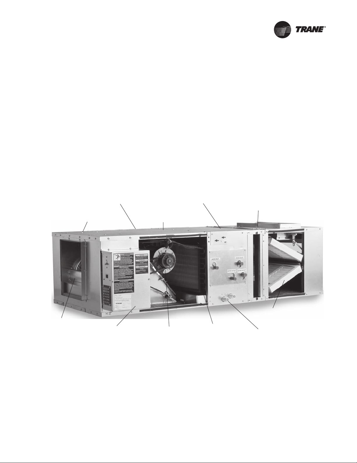
Basic unit components consist of a water coil, condensate drain pan, filter, duct collars, one fan
wheel, and motor with drive. See Figure 1. Drive components consist of sheaves, belt, and motor.
The coil, drain pan, and motor/drive assembly can easily be field-converted from right hand to left
hand configurations or vice versa.
Figure 1. Blower coil air handler unit components (model BCHC, horizontal unit)
Main coil with copper
tubes and enhanced
aluminum fins in 2-, 4-,
Unit sizes 12, 18, 24, 36,
54, 72, and 90 MBh
Knockouts in all four
corners for hanger rods
Galvanized steel
cabinet in 14-, 18-, 22-,
and 28-inch heights
or 6-row hydronic or 3-,
4-, or 6-row DX
Internal filter frame
accommodates 1- or
2-inch filters
Angle filter option and/or
Forward curved fan
Control options
include control
interface, Tracer™
ZN010, ZN510, or
ZN520
1/3 to 3 hp motor
with drive
selections from
390 to 1611 rpm
Internal 1- or
2-row auxiliary
coil in preheat
or reheat position
mixing box accommodates
2-inch filters
Main and auxiliary
drain connections on
same side of unit
Two, four, or six-row main coils are available for either hydronic cooling or heating. Three, four, or
six-row direct expansion (DX) coils are also available for cooling. An optional one, two, four, or sixrow heating coil is available factory-installed in either the preheat or reheat position. Also, a onerow preheat steam is available.
All units have an internal flat filter frame for one or two-inch filters. An optional angle filter box (two
inch only), mixing box, bottom/top filter access box, or combination angle filter mixing box is
available.
In addition, all units are available with either a basic or deluxe piping package option that includes
a variety of control valve sizes in two or three-way configurations. The basic package consists of
BCXC-SVX01B-EN 9
Page 10

General Information
a control valve and stop (ball) valves. The deluxe package consists of a control valve, a stop (ball)
valve, a circuit setter, and strainer.
Belt-drive motors range from 1/3 to 3 horsepower in a wide range of voltages. All motors have
internal thermal and current overloads, permanently sealed ball bearings, and a resilient cradle
mount to reduce noise and vibration transmission.
Variable pitch sheave drive kit options help make it possible to more accurately select design static
pressure. For additional flexibility, 115 volt single phase, two speed motors are optional.
Note: Sheaves are factory set in the middle of the range. Field adjustment of sheaves, motor, and
Units may have no controls (4 x 4 junction box) or any of four different control types:
1. control interface
2. Tracer™ ZN010
3. Tracer ZN510
4. Tracer ZN520
All control options are factory-installed and tested.
belt are required to arrive at desired rpm. Refer to the original sales order and Table 35, p. 68
for drive information.
10 BCXC-SVX01B-EN
Page 11

Pre-Installation
Receiving and Handling
Blower coil units are packaged for easy handling and storage on the job site. Upon delivery, inspect
all components for possible shipping damage. See the “Receiving Checklist” section (below) for
detailed instructions. Trane recommends leaving units and accessories in their shipping packages/
skids for protection and handling ease until installation.
Shipping Package
Blower coil air handlers ship assembled on skids with protective coverings over the coil and
discharge openings.
Ship-Separate Accessories
Field-installed sensors ship separately inside the unit’s main control panel. Piping packages,
mixing boxes, ship separately packaged on the same skid as the unit.
Receiving Checklist
Complete the following checklist immediately after receiving unit shipment to detect possible
shipping damage.
Inspect individual cartons before accepting. Check for rattles, bent carton corners, or other visible
indications of shipping damage.
If a unit appears damaged, inspect it immediately before accepting the shipment. Manually
rotate the fan wheel to ensure it turns freely. Make specific notations concerning the damage on
the freight bill. Do not refuse delivery.
Inspect the unit for concealed damage before it is stored and as soon as possible after delivery.
Report concealed damage to the freight line within the allotted time after delivery. Check with the
carrier for their allotted time to submit a claim.
Do not move damaged material from the receiving location. It is the receiver’s responsibility to
provide reasonable evidence that concealed damage did not occur after delivery.
Do not continue unpacking the shipment if it appears damaged. Retain all internal packing,
cartons, and crate. Take photos of damaged material if possible.
Notify the carrier’s terminal of the damage immediately by phone and mail. Request an
immediate joint inspection of the damage by the carrier and consignee.
Notify your Trane representative of the damage and arrange for repair. Have the carrier inspect
the damage before making any repairs to the unit.
Compare the electrical data on the unit nameplate with the ordering and shipping information
to verify the correct unit is received.
Jobsite Storage Recommendations
This unit is intended for indoor use only. To protect the unit from damage due to the elements and
prevent it from possibly becoming a contaminant source for IAQ problems, store the unit indoors.
If indoor storage is not possible, the Trane Company makes the following provisions for outdoor
storage:
1. Place the unit(s) on a dry surface or raised off the ground to assure adequate air circulation
beneath unit and to assure that no portion of the unit contacts standing water at any time.
2. Cover the entire unit with a canvas tarp only. Do not use clear, black, or plastic tarps as they
may cause excessive moisture condensation and equipment damage.
Note: Wet interior unit insulation can become an amplification site for microbial growth (mold),
which may cause odors and health-related indoor air quality problems. If there is visible
evidence of microbial growth (mold) on the interior insulation, remove and replace the
insulation prior to operating the system.
BCXC-SVX01B-EN 11
Page 12

Pre-Installation
Installation Preparation
Before installing the unit, perform the following procedures to ensure proper unit operation.
1. Verify the floor or foundation is level. Shim or repair as necessary. To ensure proper unit
operation, install the unit level (zero tolerance) in both horizontal axes. Failure to level the unit
properly can result in condensate management problems, such as standing water inside the
unit. Standing water and wet surfaces inside units can result in microbial growth (mold) in the
drain pan that may cause unpleasant odors and serious health-related indoor air quality
problem.
2. Allow adequate service and code clearances as recommended in the “Service Access” section
(below). Position the unit and skid assembly in its final location. Test lift the unit to determine
exact unit balance and stability before hoisting it to the installation location.
Service Access
See Ta b le 1 , below, and Figure 2, p. 13 for recommended service and code clearances.
WARNING
Hazardous Voltage!
Disconnect all electric power, including remote disconnects before servicing. Follow proper
lockout/tagout procedures to ensure the power can not be inadvertently energized. Failure to
disconnect power before servicing could result in death or serious injury.
Table 1. Service requirements, in. (cm)
Unit size Dimension A
12 20 (50.8)
18 25 (63.5)
24 25 (63.5)
36 37 (94.0)
54 37 (94.0)
72 45 (114.3)
90 45 (114.3)
12 BCXC-SVX01B-EN
Page 13
Pre-Installation
Figure 2. Top view of blower coil unit showing recommended service and code clearances
3
3
Rigging and Handling
Before preparing the unit for lifting, estimate the approximate center of gravity for lifting safety.
Because of placement of internal components, the unit weight may be unevenly distributed, with
more weight in the coil area. Approximate unit weights are given in “Dimensions and Weights,”
p. 15. Also, you may reference the unit weight on the unit nameplate.
Before hoisting the unit into position, use a proper rigging method such as straps, slings, or
spreader bars for protection and safety. Always test-lift the unit to determine the exact unit balance
and stability before hoisting it to the installation location.
WARNING
Improper Unit Lift!
Test lift unit approximately 24 inches to verify proper center of gravity lift point. To avoid
dropping of unit, reposition lifting point if unit is not level. Failure to properly lift unit could
result in death or serious injury or possible equipment or property-only damage.
Unit Handling Procedure
1. Position rigging sling under wood skid using spreader bars to avoid unit damage.
2. Use a forklift with caution to prevent unit damage. The fork length must be at least 68 inches
long to safely fork the unit from front or back.
3. The unit center of gravity will fall within the center of gravity block at various locations
depending on unit options.
4. See unit nameplate for unit weight.
Unit Location Recommendations
When selecting and preparing the unit installation location, consider the following
recommendations.
BCXC-SVX01B-EN 13
Page 14

Pre-Installation
1. Consider the unit weight. Reference the unit weight on the unit nameplate or in “Dimensions
and Weights,” p. 15.
2. Allow sufficient space for the recommended clearances, access panel removal, and
maintenance access. Refer to Figure 2, p. 13.
3. The installer must provide threaded suspension rods for ceiling mounted units. All units must
be installed level.
4. Coil piping and condensate drain requirements must be considered.
Allow room for proper ductwork and electrical connections. Support all piping and ductwork
independently of unit to prevent excess noise and vibration.
Skid Removal
The unit ships on skids that provide forklift locations from the front or rear. The skid allows easy
maneuverability of the unit during storage and transportation. Remove the skids before placing the
unit in its permanent location.
Remove the skids using a forklift or jack. Lift one end of the unit off of the skids. Vibration isolators
for external isolation are field supplied.
Pre-Installation Checklist
Complete the following checklist before beginning unit installation.
Verify the unit size and tagging with the unit nameplate.
Make certain the floor or foundation is level, solid, and sufficient to support the unit and
accessory weights. Refer to “Dimensions and Weights,” p. 15. Level or repair the floor before
positioning the unit if necessary.
Allow minimum recommended clearances for routine maintenance and service. Refer to unit
submittals for dimensions.
Allow one and one half fan diameters above the unit for the discharge ductwork.
14 BCXC-SVX01B-EN
Page 15
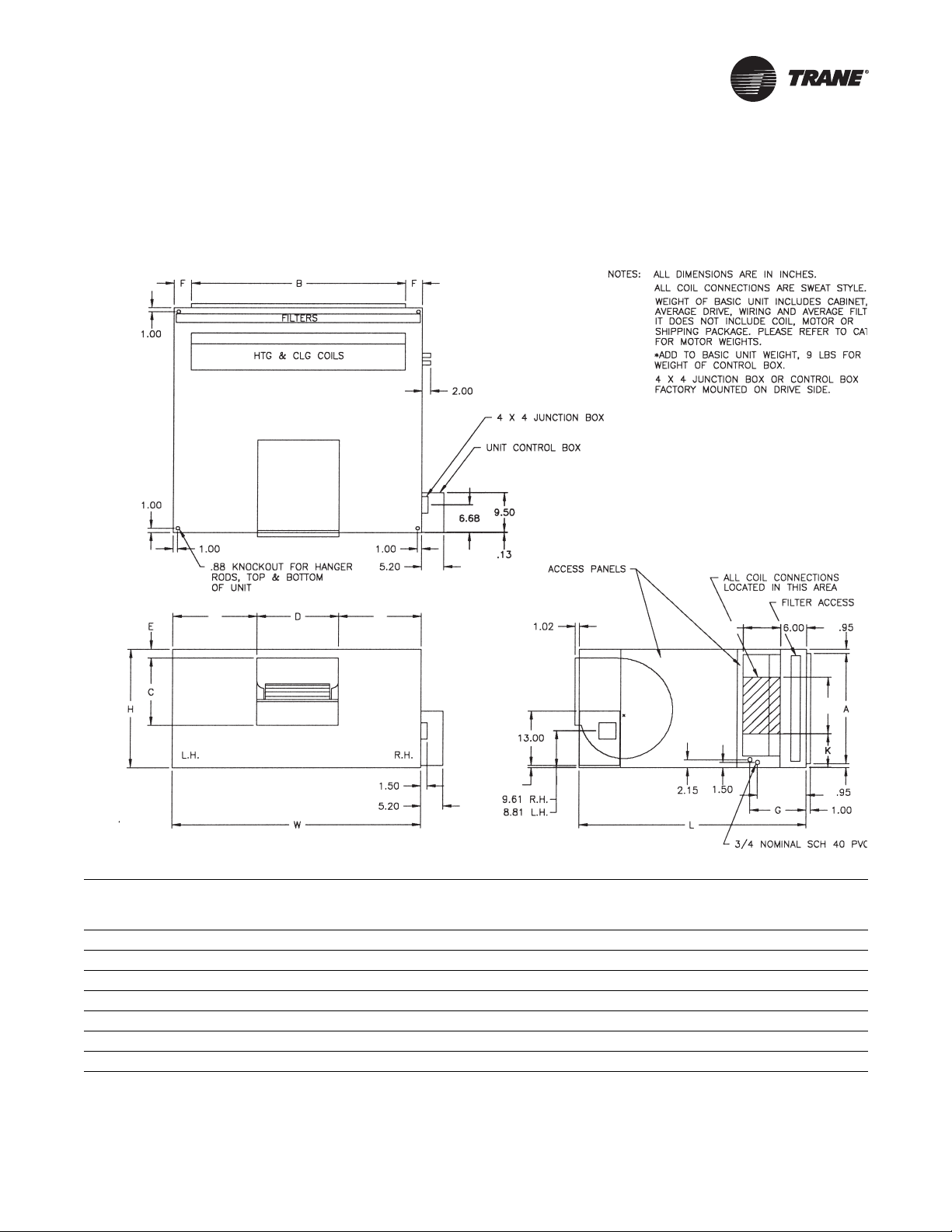
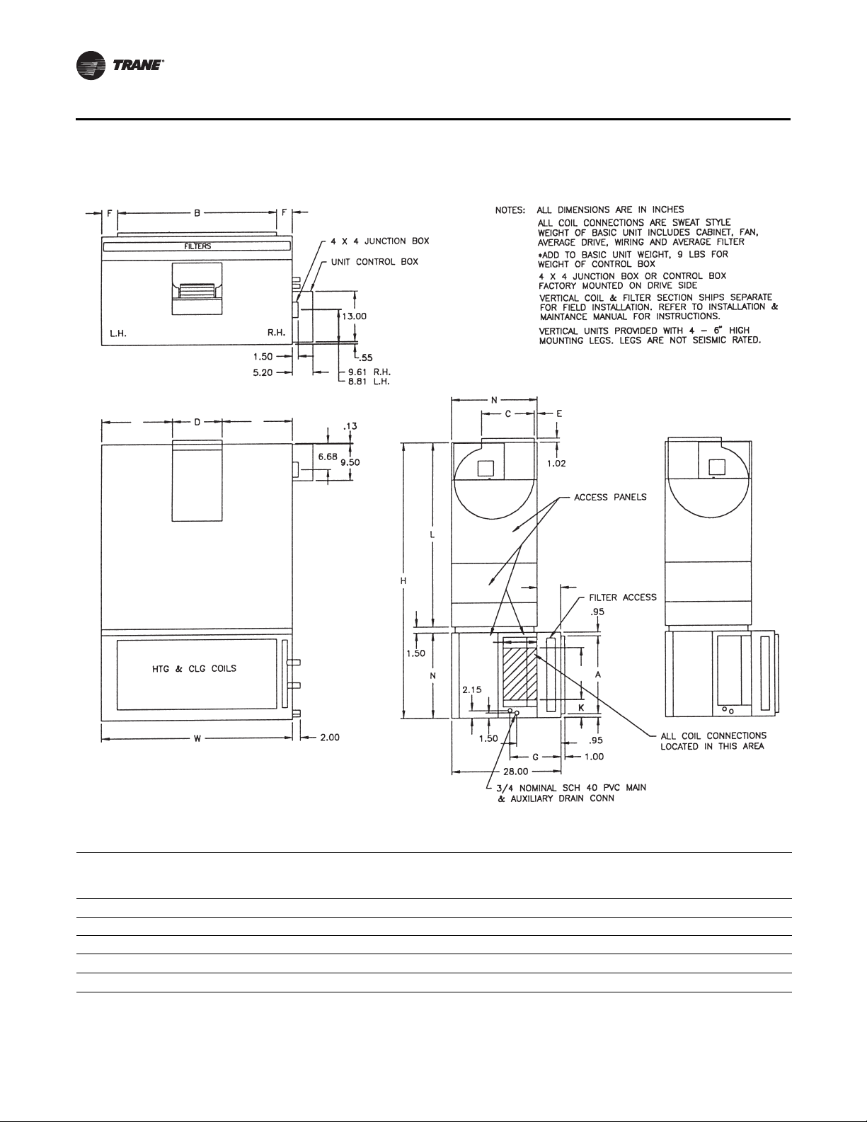
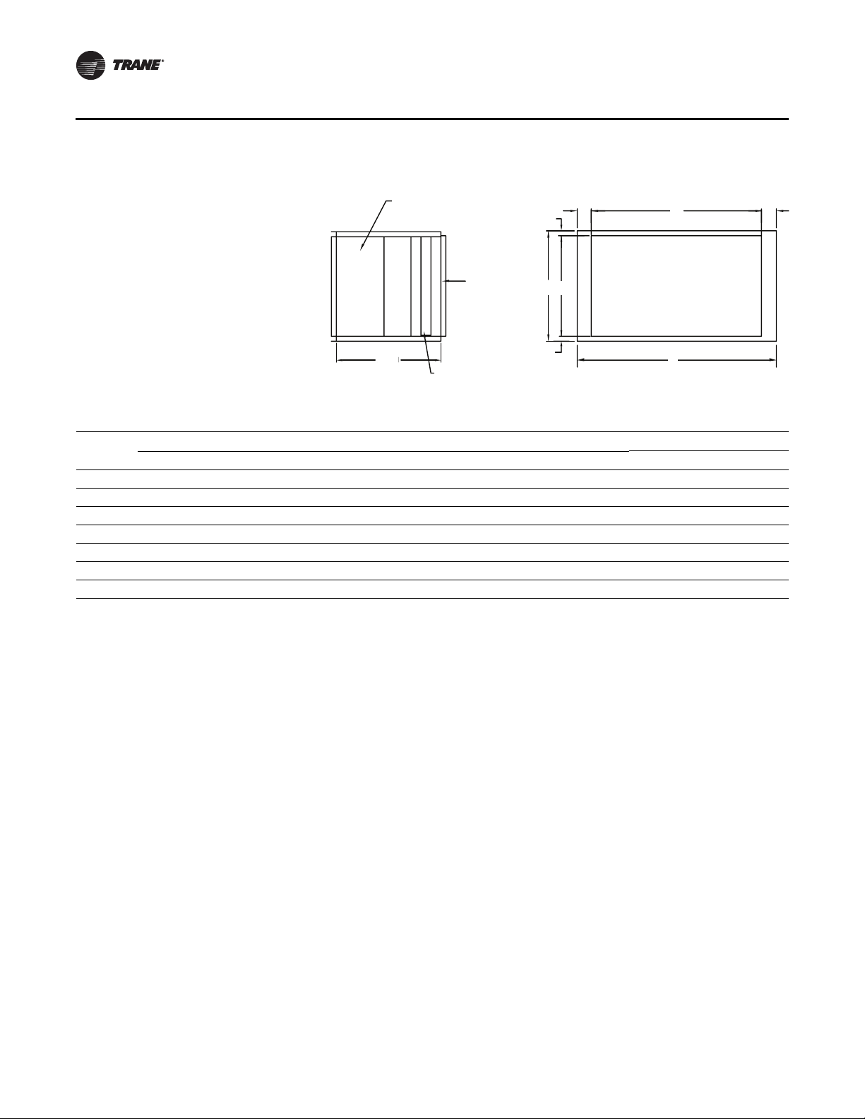
Dimensions and Weights
Horizontal Blower Coil
top view
M
M
M
*NOTE: ON UNITS WITHOUT A
BOTTOM FILTER ACCESS SECTION
P
P
Q
Q
1.5
front view
J
J
Table 2. Horizontal blower coil dimensions (in.) and weights (lb)
Unit
size H W L A B C D E FG (RH)G (LH)J (RH)J (LH) K M P Q
12 14.00 24.00 39.75 12.09 18.00 10.56 7.09 0.55 3.00 11.42 13.42 9.42 11.42 4.20 8.46 9.00 5.75 70.40
18 14.00 28.00 39.75 12.09 22.00 10.56 7.09 0.55 3.00 11.42 13.42 9.42 11.42 4.20 10.46 9.00 5.75 76.10
24 18.00 28.00 44.00 16.09 22.00 13.56 12.56 1.30 3.00 11.42 13.42 9.42 11.42 6.20 7.72 9.00 5.75 98.90
36 18.00 40.00 44.00 16.09 34.00 13.56 12.56 1.30 3.00 11.42 13.42 9.42 11.42 6.20 13.72 9.00 5.75 116.10
54 22.00 40.00 49.00 20.09 34.00 13.56 12.56 0.72 3.00 11.42 13.42 9.42 11.42 7.43 13.72 11.00 7.27 138.90
72 22.00 48.00 49.00 20.09 40.00 13.56 12.56 0.72 4.00 11.42 13.42 9.42 11.42 7.43 17.72 11.00 7.27 152.20
90 28.00 48.00 52.00 26.09 40.00 13.56 12.56 1.66 4.00 12.79 14.79 10.79 12.79 8.24 17.72 11.25 11.64 174.80
Basic
weight
unit
BCXC-SVX01B-EN 15
Page 16
Dimensions and Weights
Vertical Blower Coil
M
M
top view
front view
vertical counter swirl
configuration
*NOTE; ON UNITS WITHOUT A
TOP FILTER ACCESS SECTION
vertical preswirl
M
6.00
6.00
P
Q
J
configuration
Table 3. Vertical blower coil dimensions (in.) and weights (lb)
Unit
size H W L A B C D E FG (RH)G (LH)J (RH)J (LH) K M N P Q R
24 63.50 28.00 44.00 16.09 22.00 13.56 12.56 1.30 3.00 11.42 13.42 9.42 11.42 6.20 5.50 18.00 9.00 5.50 28.00 150.30
36 63.50 40.00 44.00 16.09 34.00 13.56 12.56 1.30 3.00 11.42 13.42 9.42 11.42 6.20 5.50 18.00 9.00 5.50 28.00 180.40
54 72.50 40.00 47.00 20.09 34.00 13.56 12.56 0.72 3.00 11.42 13.42 9.42 11.42 4.21 10.43 22.00 11.00 7.27 30.00 206.40
72 72.50 48.00 47.00 20.09 40.00 13.56 12.56 0.72 4.00 11.42 13.42 9.42 11.42 4.18 10.43 22.00 11.00 7.27 30.00 228.20
90 81.50 48.00 50.00 26.09 40.00 13.56 12.56 1.66 4.00 12.79 14.79 10.79 12.79 4.81 15.61 28.00 11.25 11.64 30.00 258.40
16 BCXC-SVX01B-EN
Basic
unit
weight
Page 17
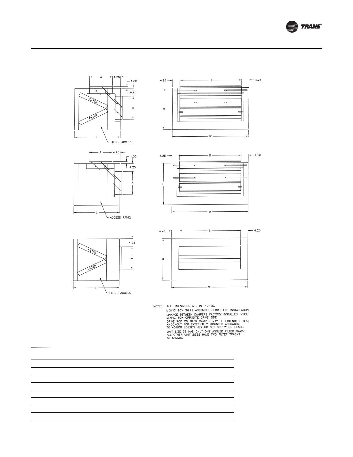
Angle Filter and Mixing Box
combination angle filter
& mixing box
mixing box
Dimensions and Weights
angle filter box
Table 4. Angle filter and mixing box dimensions (in.) and weights (lb)
Unit size H L W A B Weight
12 14.12 22.00 24.11 7.06 15.56 36.0
16 14.12 22.00 28.11 7.06 19.56 41.0
24 18.12 19.50 28.11 7.06 19.56 43.0
36 18.12 24.50 40.11 7.06 31.56 56.0
54 22.12 23.50 40.11 12.81 31.56 72.0
72 22.00 23.50 48.00 12.81 32.56 72.5
90 27.90 27.56 48.00 12.85 31.56 84.1
BCXC-SVX01B-EN 17
Page 18
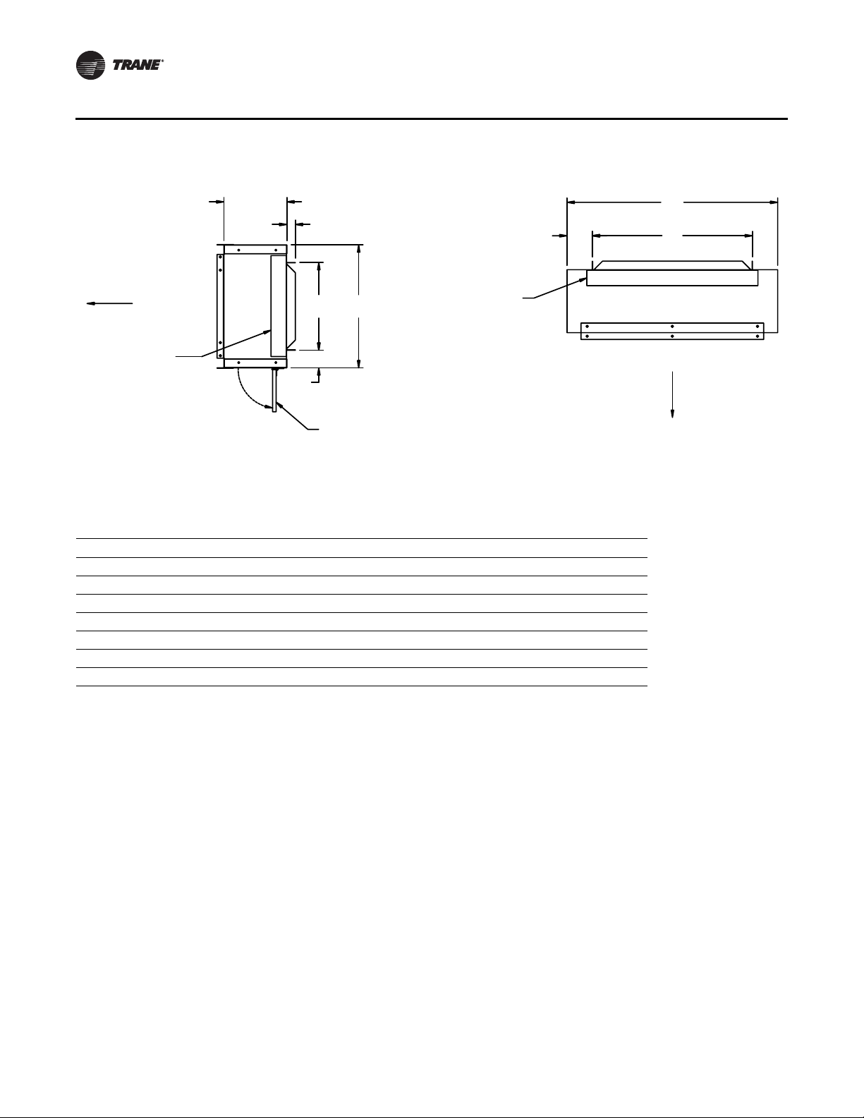
Dimensions and Weights
Bottom or Top Access Filter Box
7.17
.97
AIR FLOW
FILTER
FILTER
FILTER ACCESS PANEL
right side view
NOTES;
1. DIMENSIONS ARE IN INCHES.
2. ROTATE 180° FOR TOP ACCESS.
3. SECTIONS SHIPS ATTACHED TO THE UNIT.
Table 5. Bottom or top access filter box dimensions (in.) and weights (lb)
Unit size H W A B C D Weight
12 14.00 24.00 9.98 2.01 18.23 2.88 15
18 14.00 28.00 9.98 2.01 21.98 3.01 17
24 18.00 28.00 14.23 1.89 23.23 2.38 18
36 18.00 40.00 14.23 1.89 33.73 3.13 25
54 22.00 40.00 18.23 1.89 33.73 3.13 28
72 22.00 48.00 18.23 1.89 42.73 2.63 32
90 28.00 48.00 23.23 1.89 41.23 3.38 37
AIR FLOW
top view
18 BCXC-SVX01B-EN
Page 19
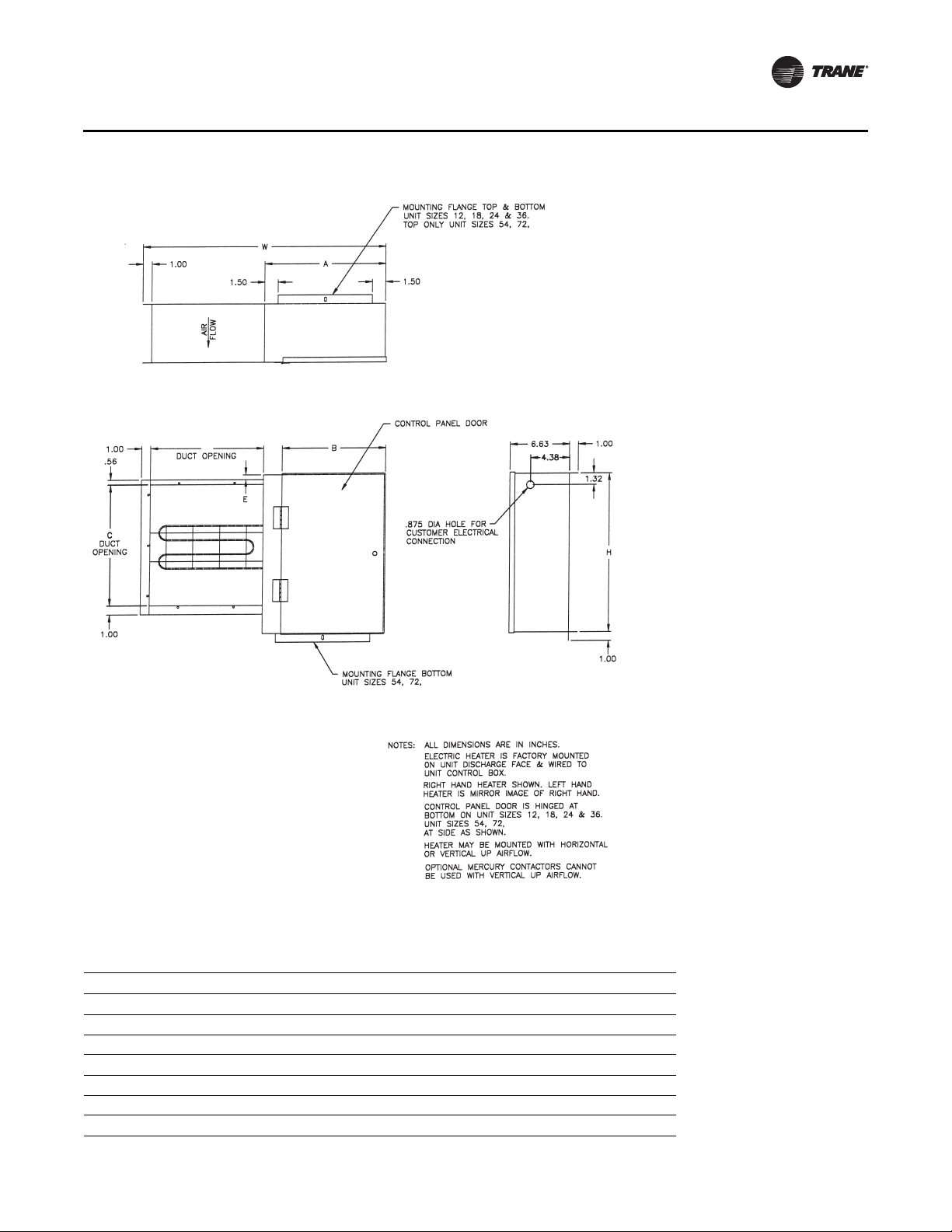
Electric Heat
Dimensions and Weights
& 90
top view
D
front view
& 90
ELECTRIC HEAT MAY NEED FIELD-SUPPLIED
EXTERNALLY-WRAPPED INSULATION IF THE UNIT
IS INSTALLED IN AN UNCONDITIONED SPACE OR
IF SWEATING IS AN ISSUE.
right side view
& 90 ARE HINGED
Table 6. Electric heat dimensions (in.) and weights (lb)
Unit size H W A B C D E Weight
12 14.06 17.88 8.13 6.79 10.50 7.75 0.03 10.0
18 14.06 19.88 10.13 8.79 10.50 7.75 0.03 10.8
24 18.06 21.25 7.63 6.29 13.50 12.63 0.80 11.3
36 18.06 27.25 13.63 12.29 13.50 12.63 0.80 12.8
54 18.06 27.25 13.63 11.67 13.50 12.63 0.22 16.0
72 18.06 27.25 13.63 11.67 13.50 12.63 0.22 17.4
90 18.06 27.25 13.63 11.67 13.50 12.63 1.16 19.2
BCXC-SVX01B-EN 19
Page 20
Dimensions and Weights
Steam Coil
NOTES:
1. FILTER ACCESS & ACCESS PANEL LOCATED
ON BOTH SIDES.
2. WEIGHT INCLUDES CABINET WITH AVERAGE FILTER,
BUT DOES NOT INCLUDE CIOL WEIGHT.
SEE GENERAL DATA SECTION FOR COIL WEIGHTS.
ACCESS PANEL
HEATING COIL
21.00
0.97
AIRFLOW
0.97
FILTER ACCESS
CC
H
A
B
W
Table 7. Steam coil box dimensions (in.) and weights (lb)
Coil Connections, NPT
Unit size
12 14.00 24.00 12.06 18.04 2.98 34 1 3/4
18 14.00 28.00 12.06 22.04 2.98 37 1 3/4
24 18.00 28.00 16.06 22.04 2.98 40 1-1/2 1
36 18.00 40.00 16.06 34.04 2.98 48 1-1/2 1
54 22.00 40.00 20.06 34.04 2.98 50 2 1
72 22.00 48.00 20.06 42.04 2.98 56 2 1
90 28.00 48.00 26.06 40.04 3.98 63 2.5 1-1/4
H W A B C Weight Supply Return
20 BCXC-SVX01B-EN
Page 21
Coil Connections
Dimensions and Weights
Table 8. Hydronic coil connection sizes, OD (in.)
Standard capacity High capacity
Unit size
12 5/8 - - 5/8 7/8 7/8
18 5/8 - - 5/8 7/8 7/8
24 5/8 - - 7/8 1-1/8 1-1/8
36 7/8 - - 7/8 1-1/8 1-1/8
54 1-1/8 1-3/8 1-3/8 1-1/8 1-1/8 1-1/8
72 1-1/8 1-3/8 1-3/8 1-1/8 1-1/8 1-1/8
90 1-1/8 1-5/8 1-5/8 1-1/8 1-1/8 1-1/8
Table 9. DX coil connection sizes, OD (in.)
Unit size
12 5/8 5/8 5/8 5/8
18 5/8 5/8 5/8 5/8
24 5/8 5/8 7/8 5/8
36 7/8 5/8 7/8 5/8
54 1-1/8 7/8 1-1/8 7/8
72 1-1/8 7/8 1-1/8 7/8
90 1-3/8 7/8 1-1/8 7/8
1-row 4-row 6-row 2-row 4-row 6-row
3- & 4-row 6-row
Suction Liquid Suction Liquid
Table 10. Steam coil connection sizes, female connection, NPT (in.)
Unit size Supply Return
12 1 3/4
18 1 3/4
24 1-1/2 1
36 1-1/2 1
54 2 1
72 2 1
90 2-1/2 1-1/4
BCXC-SVX01B-EN 21
Page 22
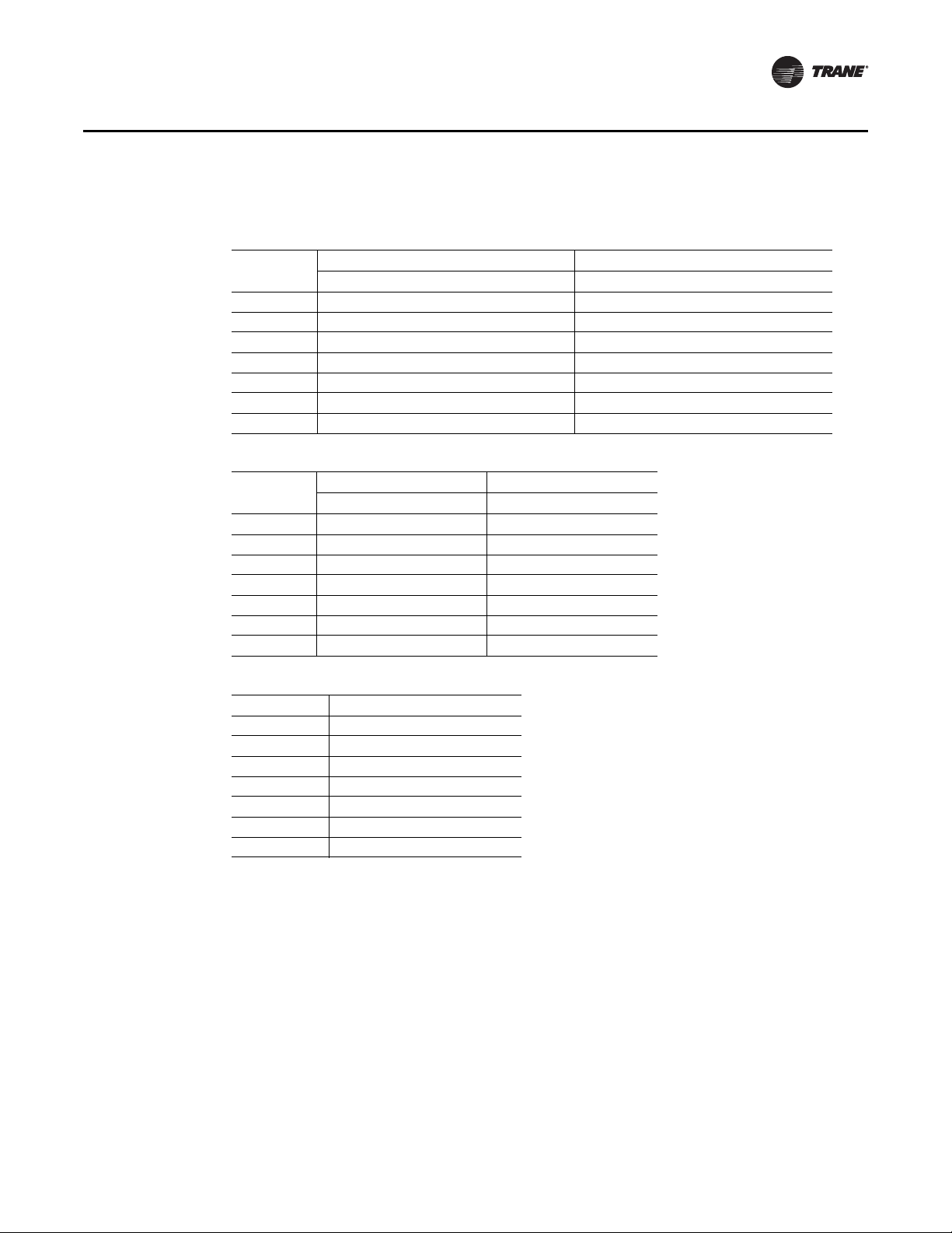
Dimensions and Weights
Piping Packages
Basic Piping
Two-way, 1/2” and 1” valve basic piping package
Two-way, 1-1/4” valve basic piping package
AB
B
A
A
B
AB
A
Three-way, 1/2” and 1” valve basic piping package
A
B
AB
E
B
F
E
A
22 BCXC-SVX01B-EN
B
Page 23
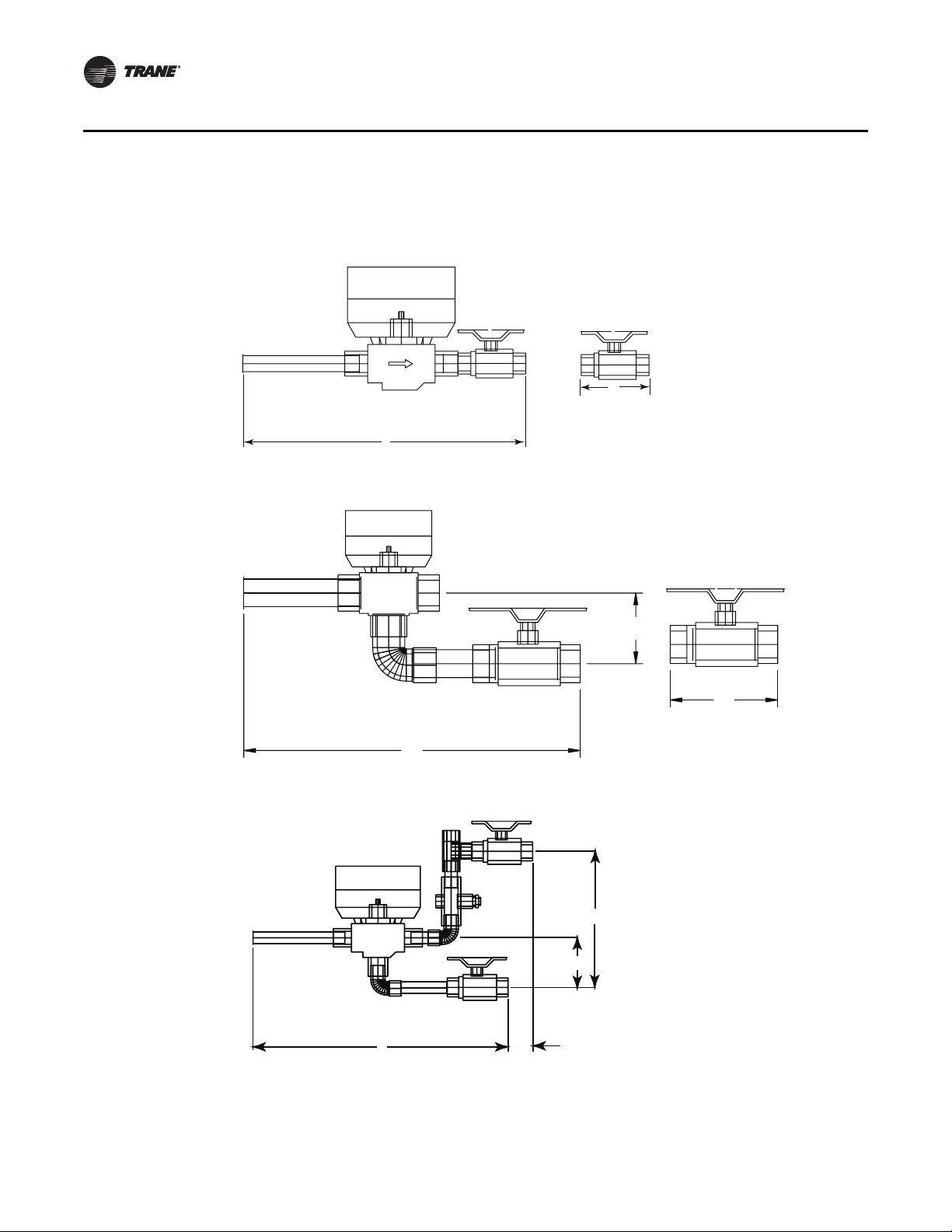
Deluxe Piping
Two-way, 1/2” and 1” valve deluxe piping package
D
AB
C
Dimensions and Weights
Two-way 1-1/4” valve deluxe piping package
D
BA
AB
C
E
BCXC-SVX01B-EN 23
Page 24
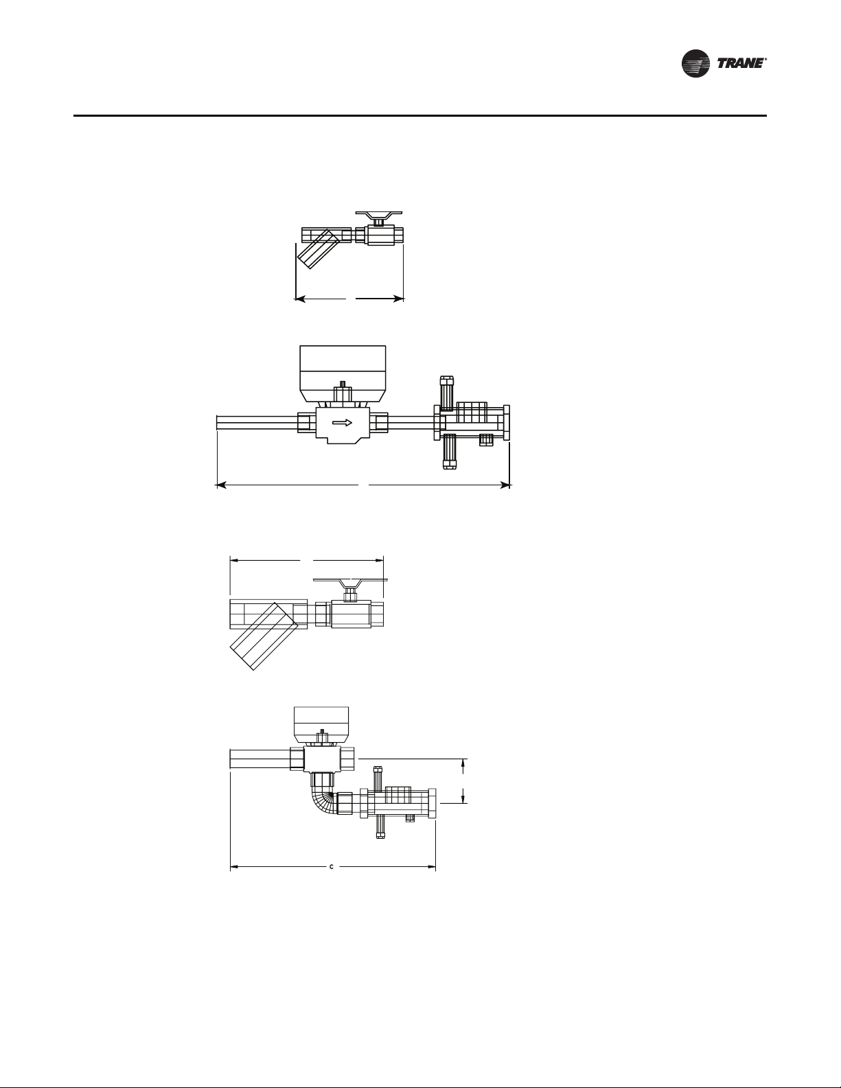
Dimensions and Weights
Three-way, 1/2” and 1” valve deluxe piping package
F
A
B
AB
E
C
D
Table 11. Piping package dimensions (in.)
Piping
package
2-way 1/2 5/8 12.025 2.650 12.625 5.650 N/A N/A
3-way 1/2 5/8 12.088 2.097 12.688 4.497 6.351 6.351
Nominal
tube size Actual size A B C D E F
1 1-1/8 13.295 4.260 13.220 9.288 3.020 N/A
3/4 7/8 15.623 1.750 15.313 6.290 6.701 6.701
1 1-1/8 13.370 3.690 13.210 9.060 9.813 9.813
1-1/4 1-3/8 16.885 3.738 16.410 10.023 3.052 10.520
24 BCXC-SVX01B-EN
Page 25
Installation Controls
Installing Wall Mounted Controls
Wall mounted zone sensors ship taped to the control box. Refer to Figure 3 for zone sensor
dimensions.
Position the controller on an inside wall three to five feet above the floor and at least 18 inches from
the nearest outside wall. Installing the controller at a lower height may give the advantage of
monitoring the temperature closer to the zone, but it also exposes the controller to airflow
obstructions. Ensure that air flows freely over the controller.
Before beginning installation, follow the wiring instructions below. Also, refer to the unit wiring
schematic for specific wiring details and point connections.
Wiring Instructions
Avoid mounting the controller in an area subject to the following conditions:
• Dead spots, such as behind doors or in corners that do not allow free air circulation.
• Air drafts from stairwells, outside doors, or unsectioned hollow walls.
• Radiant heat from the sun, fireplaces, appliances, etc.
• Airflow from adjacent zones or other units.
• Unheated or uncooled spaces behind the controller, such as outside walls or unoccupied
spaces.
• Concealed pipes, air ducts, or chimneys in partition spaces behind the controller.
Zone Sensor Installation
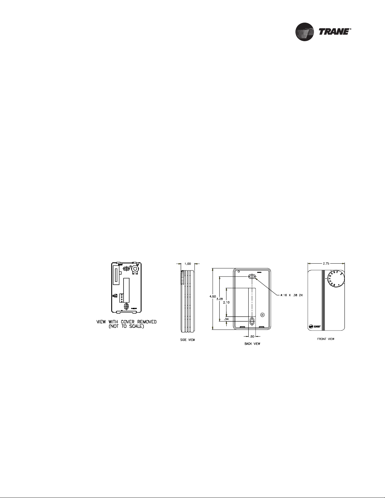
Follow the procedure below to install the zone sensor module (see Figure 3).
Figure 3. Wall-mounted zone sensor dimensions
1. Note the position of the setpoint adjustment knob and gently pry the adjustment knob from the
cover using the blade of a small screwdriver.
2. Insert the screwdriver blade behind the cover at the top of the module and carefully pry the
cover away from the base.
3. To install the zone sensor module without a junction box (directly to the wall):
a. Using the module base as a template, mark the rectangular cutout for the control wiring and
module installation holes. Ensure the base is level.
b. Set the base aside and make the cutout. Then, drill two 3/16” diameter holes approximately
one-inch deep. Insert and fully seat the plastic anchors.
c. Pull the control wires through the cutout and attach the module to the wall using the screws
provided.
4. To install the zone sensor module to a standard junction box:
a. Level and install a 2” x 4” junction box (installer supplied) vertically on the wall.
BCXC-SVX01B-EN 25
Page 26

Installation Controls
b. Pull the control wires through the cutout. Attach the module to the wall using the screws
provided.
5. Strip the insulation on the interconnection wires back 0.25 inch and connect to TB1. Screw down
the terminal blocks.
6. Replace the zone sensor cover and adjustment knob.
If installing a Tracer™ ZN510 or ZN520 zone sensor, see “Tracer Summit Communication Wiring,”
p. 27 for more information.
Communication Wiring
Units with Tracer ZN510 or ZN520 only
Note: Communication link wiring is a shielded, twisted pair of wire and must comply with
Follow these general guidelines when installing communication wiring on units with either a
Tracer™ ZN510 or ZN520 controller:
• Maintain a maximum 5000 ft. aggregate run
• Install all communication wiring in accordance with the NEC and all local codes.
• Solder the conductors and insulate (tape) the joint sufficiently when splicing communication
wire. Do not use wire nuts to make the splice.
• Do not pass communication wiring between buildings because the unit will assume different
ground potentials.
• Do not run power in the same conduit or wire bundle with communication link wiring.
applicable electrical codes.
Service Communication Wiring
Establish service communication using Rover™ service software connected to the Tracer™ ZN
controller using a twisted wire pair to one of the following connection points:
• Remote zone sensor module
• Connections on the board
This allows the technician to view and edit the Tracer™ controller configuration and troubleshoot
the unit.
Note: Unit control options and field wiring practices may limit the controller’s communication
ability.
Route interconnecting wiring from the Tracer™ controller to provide service communication at the
wall-mounted zone sensor module. Install wiring by referencing the unit wiring diagram and
Ta b l e 12 , p . 2 9 for appropriate wire sizes. After wiring is complete, connect the communication
cable (provided with the Rover™ service tool) to the telephone style RJ11 connection on the zone
sensor module. Attach the other end of the cable to a computer running Trane Rover software to
communicate.
Zone Sensors Without Interconnecting Wiring
Establish service communication to the Tracer™ ZN controller by wiring directly to the board inside
the control box. Refer to the unit-wiring diagram for appropriate communication terminals on the
board.
Once wiring is complete, Use Trane Rover™ software to communicate to the Tracer™ ZN controller.
Tracer Communications
Tracer™ ZN controllers have Comm5 communication ports. Typically, a communication link is
applied between unit controllers and a building automation system. Communication also is
possible via Rover™, Trane’s service tool.
26 BCXC-SVX01B-EN
Page 27

Peer-to-peer communication across controllers is possible even when a building automation
system is not present.You do not need to observe polarity for Comm5 communication links.
The controller provides six 0.25-inch quick-connect terminals for the Comm5 communication link
connections, as follows:
• Two terminals for communication to the board
• Two terminals for communication from the board to the next unit (daisy chain)
• Two terminals for a connection from the zone sensor back to the controller
Each controller has its own unique address or I.D. number on a Neuron chip. Setting dip switches
are not required on the Tracer™ controller.
Tracer Summit Communication Wiring
For Tracer™ ZN-controlled units that will interface with the Trane Tracer Summit® building
management system, terminate the communication wiring in the control box at the designated
terminals on the board. Reference the unit wiring diagram or submittals.
Ground shields at each Tracer™ ZN controller, taping the opposite end of each shield to prevent
any connection between the shield and anther ground. Refer to Trane publication CNT-SVX04A-EN,
Tracer ZN.520 Unit Controller - Installation, Operation and Programming Guide, for the
communication wiring diagram.
Communication wire must conform to the following specification:
• Shielded twisted pair 18 AWG
• Capacitance 23 (21-25) picofarads (pF) per foot
• Listing/Rating – 300V 150C NEC 725-2 (b) Class 2 Type CL2P
• Trane Part No. 400-20-28 or equivalent, available through Trane BAS Buying Group Accessories
catalog.
Installation Controls
BCXC-SVX01B-EN 27
Page 28

Installation Electrical
Unit Wiring Diagrams
Specific unit wiring diagrams are provided on the inside of the control panel door. Typical unit
wiring diagrams are in “Wiring Diagrams,” p. 81. Use these diagrams for connections or trouble
analysis.
WARNING
Grounding Required!
Follow proper local and state electrical codes for requirements on grounding. Failure to follow
code could result in death or serious injury.
Supply Power Wiring
Wiring must conform to NEC and all applicable code requirements.
It is the installer’s responsibility to provide adequately-sized power wires and proper unit
grounding.
Bring supply wiring through provided equipment knockouts located at the power connection point
on the unit. Equipment submittals should be referred to for the exact electrical access connection
point. Connect the power wires to the power connection point provided.
Connection to the installer-provided ground path must be made to the green wire or green
grounding screw provided on each unit.
Locate unit wiring diagrams on the inside of the control box cover. Refer to the unit-specific wiring
diagrams for wiring, connection point, and fuse installation information. Refer to the unit
nameplate for unit-specific electrical information, such as voltage, minimum circuit ampacity
(MCA), and maximum fuse size (MFS).
WARNING
Hazardous Voltage!
Disconnect all electric power, including remote disconnects before servicing. Follow proper
lockout/tagout procedures to ensure the power can not be inadvertently energized. Failure to
disconnect power before servicing could result in death or serious injury.
NOTICE
Use copper conductors only!
Unit terminals are not designed to accept other conductor types. Failure to use copper
conductors could cause equipment damage.
NOTICE
Correct phase critical!
Correct phase sequence is critical. If phase sequence of the incoming line voltage is not correct,
it could cause motor damage.
Electrical Connections
Units have one of three different connection points, depending on the unit type and options.
1. If the unit has no controls: power and ground are tucked inside of the handy box.
2. If the unit has a control interface or Tracer™ ZN controller: power and ground are inside the
control box. If the unit has a control interface or a Tracer controller, the power wires and ground
wire are inside the control box connected to a non fused disconnect switch.
28 BCXC-SVX01B-EN
Page 29

3. If the unit has a electric heat: power and ground connections are inside the electric heat control
box, connected to a non-fused disconnect switch or terminal block.
Electrical Grounding Restrictions
WARNING
Hazardous Voltage!
Disconnect all electric power, including remote disconnects before servicing. Follow proper
lockout/tagout procedures to ensure the power can not be inadvertently energized. Failure to
disconnect power before servicing could result in death or serious injury.
All sensor and input circuits are normally at or near ground (common) potential. When wiring
sensors and other input devices to the Tracer™ ZN controller, avoid creating ground loops with
grounded conductors external to the unit control circuit. Ground loops can affect the measurement
accuracy of the controller.
Note: Unit transformer IT1 provides power to the blower coil unit only and is not intended for field
connections. Field connections to the transformer IT1 may cause immediate or premature
unit component failure.
All input/output circuits (except isolated relay contacts and optically-isolated inputs) assume a
grounded source, either a ground wire at the supply transformer to control panel chassis, or an
installer supplied ground.
Note: Do not connect any sensor or input circuit to an external ground connection.
The installer must provide interconnection wiring to connect wall mounted devices such as a zone
sensor module. Refer to the unit wiring schematic for specific wiring details and point-to-point
wiring connections. Dashed lines indicate field wiring on the unit wiring schematics. All
interconnection wiring must conform to NEC Class 2 wiring requirements and any state and local
requirements. Refer to Ta bl e 1 2 for the wire size range and maximum wiring distance for each
device.
Table 12. Zone sensor maximum wiring distances, ft (m)
Installation Electrical
Wire size range Max. wiring distance
16–22 AWG 200 (60.96)
Note: Do not bundle or run interconnection wiring in parallel with or in the same conduit with any
high voltage wires (110V or greater). Exposure of interconnection wiring to high voltage
wiring, inductive loads, or RF transmitters may cause radio frequency interference (RFI). In
addition, improper separation may cause electrical noise problems. Therefore, use shielded
wire (Beldon 83559/83562 or equivalent) in applications that require a high degree of noise
immunity. Connect the shield to the chassis ground and tape at the other end.
Minimum Circuit Ampacity (MCA) and Maximum Fuse Size (MFS) Calculations
for Units with Electric Heat
Use these formulas to calculate the MCA and MFS.
Heater amps = (heater kW x 1000)/heater voltage
Note: Use 120V heater voltage for 115V units. Use 240V heater voltage for 230V units. Use 480V
heater voltage for 460V units. Use 600V heater voltage for 575V units.
MCA = 1.25 x (heater amps + all motor FLAs)
MFS or HACR type circuit breaker = (2.25 x largest motor FLA) + second motor FLA + heater amps
(if applicable)
HACR (Heating, Air-Conditioning and Refrigeration) type circuit breakers are required in the branch
circuit wiring for all units with electric heat.
BCXC-SVX01B-EN 29
Page 30

Installation Electrical
See Ta b le 1 3 for electric heat kW and Table 14, p. 31 for motor FLAs.
Select a standard fuse size or HACR type circuit breaker equal to the MCA.
Use the next larger standard size if the MCA does not equal a standard size.
Standard fuse sizes are: 15, 20, 25, 30, 35, 40, 45, 50, 60 amps
Useful Formulas
kW = (cfm x ΔT)/3145
ΔT = (kW x 1000)/voltage
Single phase amps = (kW x 1000)/voltage
Three phase amps = (kW x 1000)/(voltage x 1.73)
Electric heat MBh = (Heater kW) (3.413)
Table 13. Available electric heat, min–max (kW)
Voltage
115/60/1 1–3 1–3 1–3 1–3 1–3 1–3 1–3
208/60/1 1–4 1–6 1–8 1–8 1–8 1–8 1–8
230/60/1 1–4 1–6 1–8 1–8 1–8 1–8 1–8
277/60/1 1–4 1–6 1–8 1–11 1–11 1–11 1–11
208/60/3 1–4 1–6 1–8 1–11 1–12 1–12 1–12
230/60/3 1–4 1–6 1–8 1–11 1–12 1–12 1–12
460/60/3 1.5–4 1.5–5 1–8 1–11 1–16 1–21 1–30
575/60/3 2–4 2–4 1–8 1–11 1–16 1–21 1–30
220/50/1 1–4 1–6 1–8 1–8 1–8 1–8 1–8
240/50/1 1–4 1–6 1–8 1–8 1–8 1–8 1–8
380/50/3 1–4 1–5 1–8 1–11 1–16 1–20 1–28
415/50/3 1.5–4 1.5–5 1–8 1–11 1–16 1–21 1–30
190/50/3 N/A N/A N/A N/A N/A N/A N/A
Notes:
1. Heaters are available in the fo llowin g K w increments: 1. 0, 1.5, 2.0, 2.5, 3.0, 3. 5, 4.0, 4 .5, 5.0, 5. 5,
2. Magnetic contactors are standard. Mercury contactors are available on horizontal units only.
3. Units with electric heat are available with or without door interlocking disconnect switch.
4. Units with electric heat are available with or without line fuses.
5. Units with electric heat must not be run below the minimum cfm listed in the general data section.
6. Electric heat is balanced staging: 1 stage = 100%, 2 stages = 50%/50%
7. Electric heat is not available on 190/50/3 units.
8. For two-speed units not being controlled by the Tracer™ family of controls, a 0.2-second delay for
Unit size
12 18 24 36
6.0, 6.5, 7.0, 7.5, 8.0, 9.0, 10.0, 11.0, 12.0, 13.0, 14.0, 15.0, 16.0, 17.0, 18.0,19.0, 20.0, 21.0,
22.0, 24.0, 26.0, 28.0, 30.0.
speed switching needs to be incorporated into the control sequence.
54
72 90
30 BCXC-SVX01B-EN
Page 31

Installation Electrical
Table 14. Motor electrical data
Voltage Voltage range rpm Rated hp lb FLA LRA
115/60/1
Two-speed
115/60/1
208–230/60/1
277/60/1
208/60/3
230/60/3
460/60/3
575/60/3
Note: For two-speed units not being controlled by the Tracer™ family of controls, a 0.2-second delay for speed switching needs
to be incorporated into the control sequence.
104–126 1750 1/3 18 5.8 22.8
1/2 21 7.2 30.4
3/4 29 12.0 58.4
1.0 29 12.8 58.4
104–126 1750/1160 3/4 40 8.9/6.1 42.0
1.0 41 11.5/8.1 58.2
187–253 1750 1/3 18 3.1 11.4
1/2 21 3.6 15.2
3/4 29 6.0 29.2
1.0 29 6.4 29.2
249–305 1750 1/3 15.5 2.5 12.1
1/2 21.5 3.6 19.3
3/4 25 4.3 25.3
1.0 29 5.6 32.6
187–229 1750 1/2 22 2.3 11.4
3/4 26 2.9 15.9
1.0 28 3.5 20.2
1.5 29 4.8 30.0
2.0 34 6.2 38.5
3.0 49 8.6 55.1
207–253 1750 1/2 22 2.4 12.8
3/4 26 3.0 18.6
1.0 28 3.6 23.0
1.5 29 4.8 33.4
2.0 34 6.2 43.6
3.0 49 8.6 62.0
414–506 1750 1/2 22 1.2 6.4
3/4 26 1.5 9.3
1.0 28 1.8 11.5
1.5 29 2.4 16.7
2.0 34 3.1 21.8
3.0 49 4.3 31.0
518–632 1750 3/4 20.5 1.1 7.5
1.0 22.5 1.4 9.0
1.5 31 1.9 13.3
2.0 36 2.5 17.9
3.0 49 3.3 23.7
BCXC-SVX01B-EN 31
Page 32

Installation Electrical
Table 14. Motor electrical data (continued)
Voltage Voltage range rpm Rated hp lb FLA LRA
220/50/1
240/50/1
190/50/3
380/50/3
415/50/3
Note: For two-speed units not being controlled by the Tracer™ family of controls, a 0.2-second delay for speed switching needs
198–242 1450 1/3 20.5 3.0 15.6
1/2 25 3.6 20.5
3/4 29 5.2 25.6
1.0 38 9.3 52.2
216–264 1450 1/3 20.5 3.3 17.1
1/2 25 4.0 22.7
3/4 29 5.5 39.1
1.0 38 10.6 57.8
171–209 1450 1/3 22 1.1 5.6
342–418 1/2 26 1.4 7.8
3/4 28 1.7 9.8
1.0 29 2.1 14.6
1.5 34 2.8 18.7
2.0 49 3.6 27.2
374–456 1450 1/3 22 1.2 6.8
1/2 26 1.5 9.4
3/4 28 1.9 11.0
1.0 29 2.5 17.4
1.5 34 3.1 22.6
2.0 49 3.6 32.3
to be incorporated into the control sequence.
32 BCXC-SVX01B-EN
Page 33
Installation Mechanical
WARNING
Hazardous Voltage!
Disconnect all electric power, including remote disconnects before servicing. Follow proper
lockout/tagout procedures to ensure the power can not be inadvertently energized. Failure to
disconnect power before servicing could result in death or serious injury.
Installing the Unit
Follow the procedures below to install the blower coil unit.
Horizontal Units, Model BCHC
Install horizontal units suspended from the ceiling with 3/8” threaded rods that are field provided.
There are two knockouts in each corner of the unit for installation of the threaded rods. Ensure the
ceiling opening is large enough for unit installation and maintenance requirements.
BCHC Installation Procedure
Materials needed:
• threaded rods, 3/8” (4)
• nuts (8)
• flat washers or steel plates (8)
• vibration isolator hangers or turnbuckles (4)
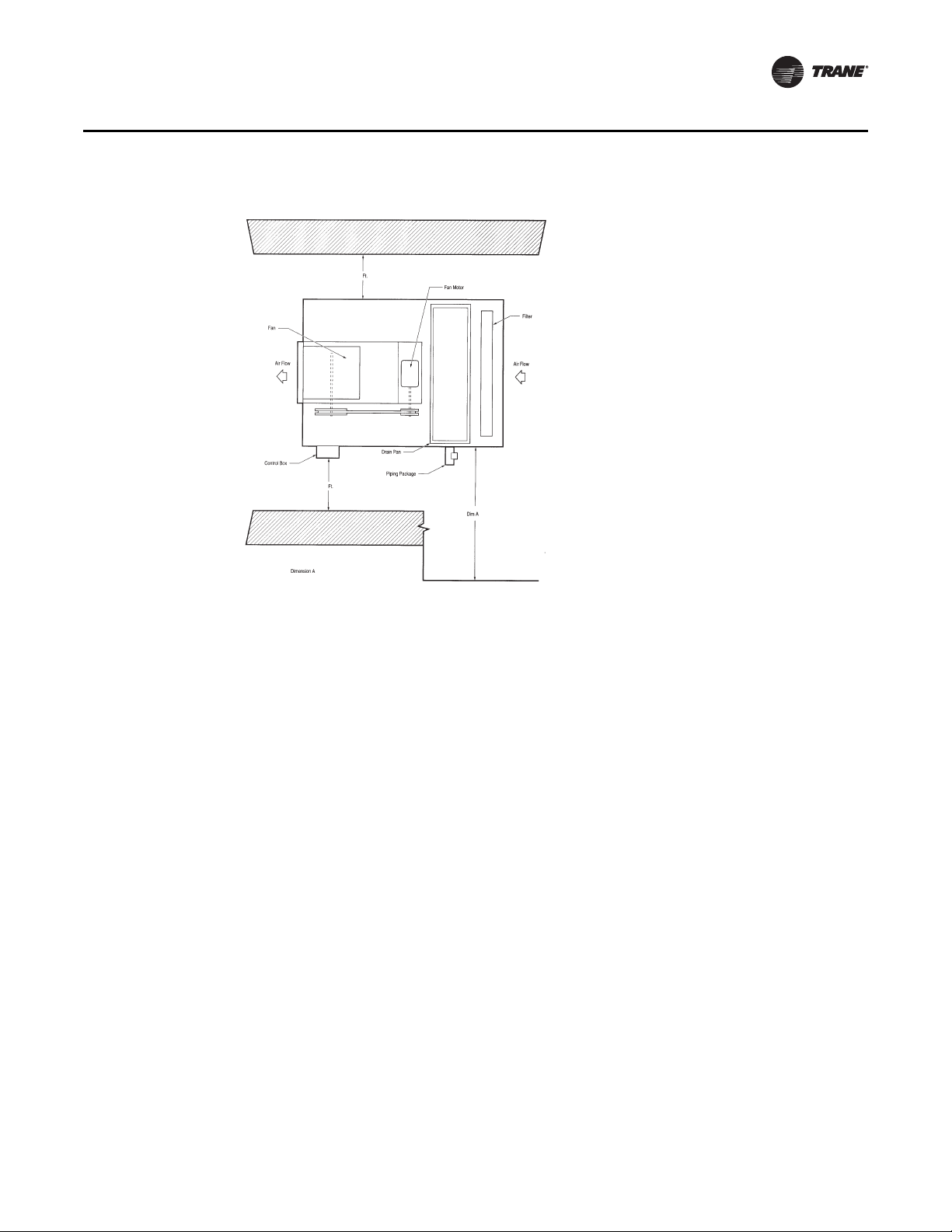
1. Determine the unit mounting hole dimensions. Prepare the hanger rod isolator assemblies,
which are field provided, and install them in the ceiling. Trane recommends using threaded rods
to level the unit. Consult the unit nameplate or “Dimensions and Weights,” p. 15 in th is ma nua l
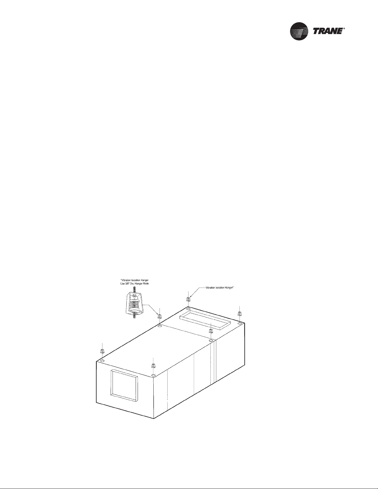
for the unit weight. See Figure 4 for proper horizontal unit installation.
Figure 4. How to hang the horizontal unit from the ceiling
2. Remove motor access panels and filter access panels.
3. Punch out the eight knockouts in the top and bottom panels.
BCXC-SVX01B-EN 33
Page 34
Installation Mechanical
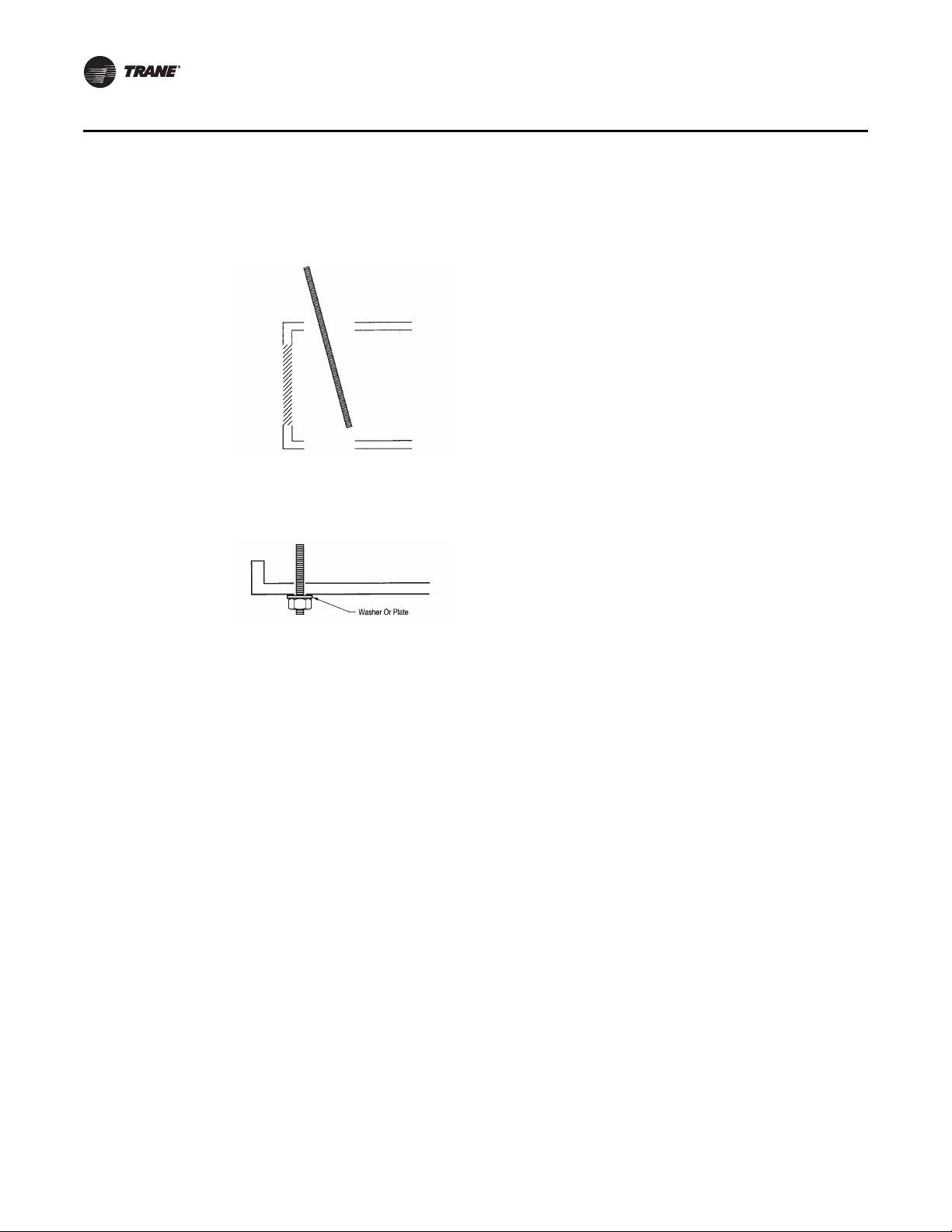
4. Guide the threaded rod through the unit from the top, careful not to damage insulation or
wiring. See Figure 5. Insert the threaded rod at an angle to help prevent internal unit damage.
Figure 5. When inserting the threaded rod though the unit knockouts, angle it through the top,
5. Put a nut and large flat washer or steel plate on the bottom of the threaded rod. See Figure 6.
Figure 6. Correct placement of washer or steel plate and nut between threaded rod and unit.
careful not to damage unit coil or insulation.
This helps prevent air leakage.
6. Put a nut and flat washer or steel plate on the top to prevent air leakage.
7. Thread the top of the rod into the isolator or turnbuckle.
8. Hoist the unit to the suspension rods and attach with washers and lock–nuts (see Figure 4, p. 33
for details).
9. Level the unit for proper coil drainage and condensate removal from the drain pan. Refer to
“Condensate Drain Connections,” p. 36.
10. Connect the ductwork to the unit. Refer to “Duct Connections,” p. 37.
Vertical Units, Model BCVC
Install vertical units on the floor. Units are provided with legs that are field-installed to help
accommodate a U-trap on the drain connection, if necessary. A field-fabricated inlet plenum is not
34 BCXC-SVX01B-EN
Page 35
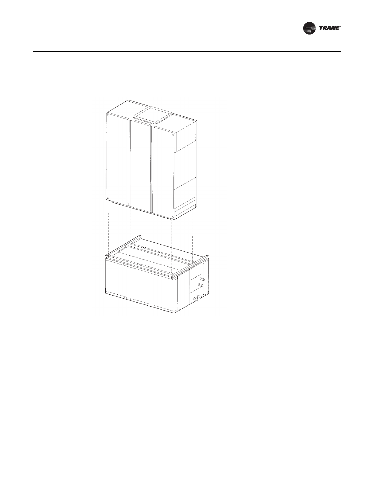
Installation Mechanical
required. The unit is shipped in two pieces, and can be arranged in either a pre-swirl or counterswirl inlet configuration (see Figure 7).
Figure 7. Typical vertical unit installation
Heating Coil Option
Note: The hydronic heating coil option is factory installed in either the reheat or preheat position.
Coils can be rotated for either right or left-hand connections.
If you need to rotate the hydronic heating coil option to change the coil connection side, follow the
procedure below.
1. Remove both coil access panels.
2. Remove the coil and rotate to change connection position.
3. Exchange coil patch plates.
4. Knock out drain pipe connections on new coil hand access panel.
5. Plug old drain connections.
Mixing Box Option
Materials provided:
• mounting legs
BCXC-SVX01B-EN 35
Page 36

Installation Mechanical
• interconnecting linkage, LH or RH attachment
Materials needed:
• grooved and extendible drive rods, 1/2-inch O.D. grooved
• screws
The mixing box option ships separately for field installation. It has two low-leak, opposed blade
dampers and all necessary interconnecting linkage components for left or right hand attachment
onto 1/2-inch O.D. grooved, extendible drive rods. Also, mounting legs are provided for floor
mounting on a vertical unit. Knockouts are provided to suspend the mixing box from the ceiling
horizontally.
Mixing Box Installation Procedure
1. Support the mixing box independent of the unit in the horizontal position.
2. Install the mixing box as a sleeve around the duct collar of the filter frame. To attach the mixing
box to the filter frame, insert screws through the matching the holes on all sides of the mixing
box and filter frame.
3. Install the linkage, following the procedure below.
Linkage Installation Procedure
1. Attach the linkage on either the right or left side of the mixing box following the procedure
below.
2. Open the damper blades fully. Locate drive rods on the LH or RH side for linkage attachment.
Loosen drive rod set screw, without removing.
3. Remove knockouts on side access panel adjacent to the drive rods.
4. Pierce a hole through the insulation at the knockouts to allow the drive rod to extend freely
through side of mixing box. Cut away insulation sufficiently to allow drive rod to turn smoothly.
5. Extend drive rod end at desired position beyond side of unit. Tighten drive rod set screws.
6. Attach linkage and tighten all set screws. Note that neither hand levers are provided. However,
mixing box actuators are a factory-provided option that ship inside the mixing box when
ordered.
7. Position linkage so both sets of dampers operate freely and so that when one damper is fully
open, the other is fully closed.
Condensate Drain Connections
Note: It is the installer’s responsibility to provide adequate condensate piping to prevent potential
water damage to the equipment and/or building.
Size the main drain lines and trap them the same size as the drain connection, which is 3/4”
schedule 40 PVC, 1.050” O.D. on blower coils.
If drain pan removal is required, make the main and auxiliary drain connections with compression
fittings. Follow the procedure below to remove the drain pan.
1. Remove the opposite side coil access panel.
2. Remove the drain pan clips.
3. Disconnect drain lines.
4. Remove the sheet metal screw.
5. Pull out drain pan through the opposite side.
Note: Prime drain traps to prevent the drain pan overflow.
36 BCXC-SVX01B-EN
Page 37
Installation Mechanical
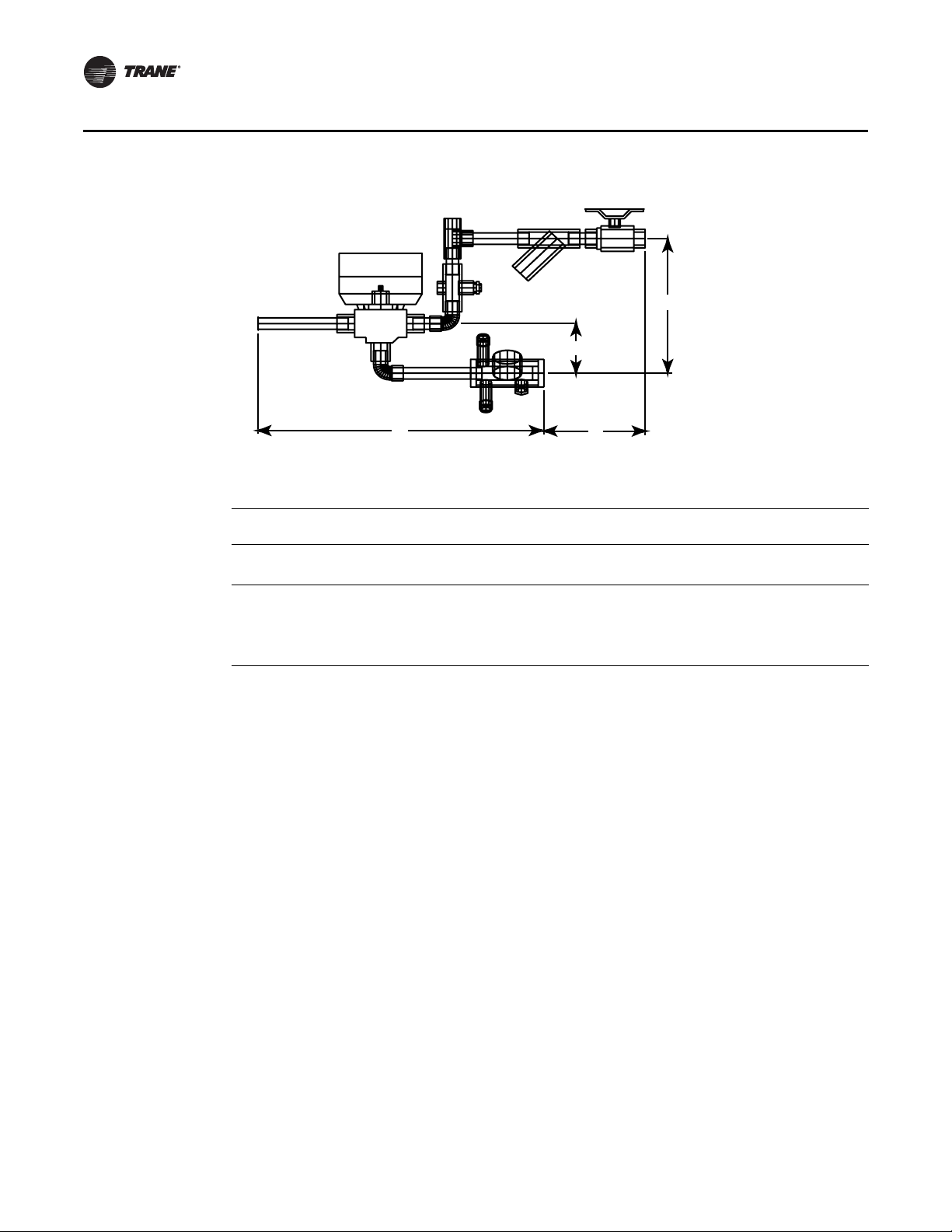
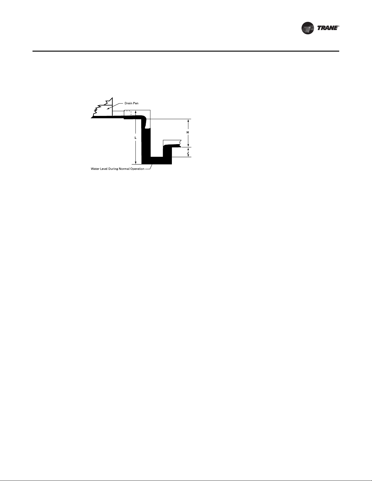
Plug or trap the auxiliary connection to prevent air from being drawn in and causing carryover (see
Figure 8).
Figure 8. Recommended drain trap installation for draw-through units
‘
H = 1” of length for each 1” of negative pressure + 1”additional
J = 1/2 of H
L = H + J + pipe diameter + insulation
All drain lines downstream of the trap must flow continuously downhill. If segments of the line are
routed uphill, this can cause the drain line to become pressurized. A pressurized drain line may
cause the trap to back up into the drain pan, causing overflow.
Duct Connections
Install all air ducts according to the National Fire Protection Association standards for the
“Installation of Air Conditioning and Ventilation Systems other than Residence Type (NFPA 90A)
and Residence Type Warm Air Heating and Air Conditioning Systems (NFPA 90B).
Make duct connections to the unit with a flexible material such as heavy canvas to help minimize
noise and vibration. If a fire hazard exists, Trane recommends using Flexweave 1000, type FW30
or equivalent canvas. Use three inches for the return duct and three inches for the discharge duct.
Keep the material loose to absorb fan vibration.
Run the ductwork straight from the opening for a minimum of 1-1/2 fan diameters. Extend
remaining ductwork as far as possible without changing size or direction. Do not make abrupt turns
or transitions near the unit due to increased noise and excessive static losses. Avoid sharp turns
and use elbows with splitters or turning vanes to minimize static losses.
Poorly constructed turning vanes may cause airflow generated noise. Align the fan outlet properly
with the ductwork to decrease duct noise levels and increase fan performance. Check total external
static pressures against fan characteristics to be sure the required airflow is available throughout
the ductwork.
To achieve maximum acoustical performance, minimize the duct static pressure setpoint.
BCXC-SVX01B-EN 37
Page 38
Installation Piping
Water Coil Connections
Water coils have sweat connections. Reference coil connection dimensions in “Dimensions and
Wei ght s,” p. 1 5. Proper installation and piping is necessary to ensure satisfactory coil operation and
prevent operational damage. Water inlet and outlet connections extend through the coil section
side panel (see Figure 9). Follow standard piping practices when piping to the coil.
Figure 9. Horizontal unit coil connect location
NOTICE
Potential coil-freeze condition!
Make provisions to drain the coil when not in use to prevent coil freeze-up. Failure to follow this
procedure could result in equipment/property damage.
Piping Packages
Piping packages ship separate for field installation and have sweat type connections.
Interconnecting piping is field provided.
When brazing piping, follow these guidelines to prevent piping component damage.
1. Avoid exposing piping components to high heat when making sweat connections.
2. Protect the closest valve to the connection with a wet rag.
3. Ensure the circuit balancing valve option is in the unseated position.
Refrigerant Coil Piping
The DX cooling coil in a BCHC/BCVC unit is equipped with a single distributor (single-circuited).
Exception: size 72 and 90 six-row DX cooling coils are horizontally split and have two distributors
(double-circuited) which may be manifolded to a single refrigeration circuit in a condensing unit.
Some condensing units have two, independent refrigeration circuits. Do not manifold two,
independent refrigeration circuits into a single-circuited DX (evaporator) coil.
Note: Refer to “Warnings, Cautions and Notices” for information on handling refrigerants.
Units that are UL listed shall not have refrigerant temperatures and pressures exceeding that listed
on the unit nameplate.
Follow accepted refrigeration piping practices and safety precautions for typical refrigerant coil
piping and components. Specific recommendations are provided with the compressor unit,
including instructions for pressure-testing, evacuation, and system charging. Leak test the entire
refrigerant system after all piping is complete. Charge the unit according to approximate weight
requirements, operating pressures, and superheat/subcooling measurements. Adjust the thermal
expansion valve setting, if necessary, for proper superheat.
Liquid Line
Line Sizing. Properly sizing the liquid line is critical to a successful application. If provided, use
the liquid line size recommended by the manufacturer of the compressor unit. The selected tube
38 BCXC-SVX01B-EN
Page 39

Installation Piping
diameter must be as small as possible, while still providing at least 5°F [2.7°C] of subcooling at the
expansion valve throughout the operating envelope.
Routing. Install the liquid line with a slight slope in the direction of flow so that it can be routed
with the suction line. Minimize tube bends and reducers because these items tend to increase
pressure drop and reduce subcooling at the expansion valve.
Insulation. The liquid line is generally warmer than the surrounding air, so it does not require
insulation.
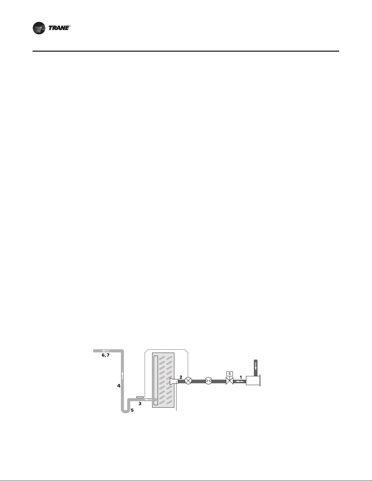
Components. Liquid-line refrigerant components necessary for a successful job include an
expansion valve, moisture indicating sight glass, filter drier, manual ball shutoff valves, access
port, and possibly a solenoid valve. Position these components as close to the evaporator as
possible.
• Thermal expansion valve (TEV)
Select the TEV based on the actual evaporator capacity, considering the full range of loadings.
Verify that the valve will successfully operate at the lightest load condition, considering if hot
gas bypass is to be used. For improved modulation, choose a TEV with balanced port
construction and an external equalizer connection. The valve must be designed to operate
against a back pressure of 20 psi higher than actual evaporator pressure. Install the TEV directly
on the coil liquid connection (distributor provided).
The remote expansion-valve bulb should be firmly attached to a straight, well-drained,
horizontal section of the suction line. The external equalizer line should be inserted
downstream of the remote bulb.
• Moisture-indicating sight glass
Install a moisture-indicating sight glass in the liquid line between the expansion valve and filter
drier. The sight glass should be sized to match the size of the liquid line.
• Filter drier
Install a properly sized liquid line filter-drier upstream from the expansion valve and as close
to the evaporator coil as possible. Select the filter-drier for a maximum pressure drop of 2 psi
at the design condition.
Manual, ball-type shutoff valves on either side of the filter drier allows replacement of the core
without evacuating the entire refrigerant charge.
• Access port
The access port allows the unit to be charged with liquid refrigerant and is used to determine
subcooling. This port is usually a Schraeder valve with a core.
• Solenoid valve
If required by the compressor unit, install the solenoid valve between the filter drier and sight
glass.
NOTICE
Valve Dam age !
Disassemble the thermal expansion valve before completing the brazing connections. If
necessary, wrap the valve in a cool wet cloth while brazing. Failure to protect the valve from
high temperatures could damage internal components.
Suction Line
Line sizing. Properly sizing the suction line is critical for ensuring that the oil returns to the
compressor throughout the system operating envelope. If provided, use the suction line size(s)
recommended by the manufacturer of the compressor unit. The selected tube diameter(s) must
maintain adequate refrigerant velocities at all operating conditions.
BCXC-SVX01B-EN 39
Page 40
Installation Piping
Routing. To prevent residual or condensed refrigerant from “free-flowing” toward the
compressor, install the suction line so it slopes slightly—1 inch per 10 feet of run [1 cm per 3 m]—
toward the evaporator. Avoid putting refrigerant lines underground. Refrigerant condensation,
installation debris inside the line, service access, and abrasion/corrosion can quickly impair system
reliability.
Insulation. After operating the system and testing all fittings and joints to verify the system is
leak-free, insulate the suction lines to prevent heat gain and unwanted condensation.
Components. Installing the suction line requires field installation of these components: an
access port and possibly a suction filter. Position them as close to the compressor as possible.
• Access port
The access port is used to determine suction pressure and adjust the TEV. It should be located
near the external equalizer line connection. This port is usually a Schraeder valve with a core.
• Suction filter
If required by the compressor unit, a replaceable-core suction filter is installed as close to the
compressor unit as possible. Adding manual, ball-type shutoff valves upstream and
downstream of the filter simplifies replacement of the filter core.
Field-Installing Evaporator Piping
See Figure 10 and refer to the instructions below to field-install evaporator piping.
1. Pitch the liquid line slightly—1 in./10 ft [1 cm/3 m]—so that the refrigerant drains toward the
evaporator.
2. Provide one expansion valve per distributor.
3. Slightly pitch the outlet line from the suction header toward the suction riser — that is, 1 in./10
ft [1 cm/3 m] in the direction of flow. Use the tube diameter that matches the suction-header
connection.
4. For the vertical riser, use the tube diameter recommended by the condensing unit
manufacturer. Assure the top of the riser is higher than the evaporator coil.
5. Arrange the suction line so the refrigerant vapor leaving the coil flows downward, below the
suction-header outlet, before turning upward.
6. Pitch the suction line slightly—1 in./10 ft [1 cm/3 m]—so the refrigerant drains toward the
evaporator.
7. Insulate the suction line.
Figure 10. Field-installed evaporation piping example
suction line
Evaporator Coil with
Standard Circuiting
liquid
sight
glass
thermal
expansion
valve (TXV)
distributor
40 BCXC-SVX01B-EN
valve
line
filter driersolenoid
Page 41

Steam Piping
Installation Piping
Proper installation, piping and trapping is necessary to insure satisfactory heating coil operation
and prevent operational damage under service conditions. These installation recommendations
and piping diagram (see Figure 11, p. 42) must be followed to assure satisfactory, trouble-free
operation.
General
1. Support all piping independently of coils.
2. Provide swing joints or flexible fittings in all piping connections adjacent to heating coils to
absorb expansion and contraction strains.
3. Install coils so air passes through fins in proper direction (stenciled on top of coil channel).
Steam Coils
NOTICE
Coil Condensate!
Condensate must flow freely from the coil at all times to prevent coil damage from water
hammer, unequal thermal stresses, freeze-up and/or corrosion. In all steam coil installations, the
condensate return connections must be at the low point of the coil. Failure to follow these
instructions could result in equipment damage.
1. Install 1/2-inch 15-degree swing check vacuum breaker in unused condensate return tapping as
close as possible to coil. Vent vacuum breaker line to atmosphere or connect into return main
at discharge side of steam trap. Vacuum relief is particularly important when coil is controlled
by modulating steam supply or two-position (on-off) automatic steam supply valve.
2. Proper steam trap selection and installation is necessary for satisfactory coil performance and
service life.
a. Select trap based on maximum possible condensate rate and recommended load factors.
b. Locate steam trap discharge at least 12 inches below condensate return tapping. This
provides sufficient hydrostatic head pressure to overcome trap losses and assure complete
condensate removal.
c. Float and thermostatic traps are preferred because of gravity drain and continuous
discharge operation.
d. Use float and thermostatic traps with atmospheric pressure gravity condensate return with
automatic controls or where possibility of low pressure supply steam exists.
e. Bucket traps should only be used when supply steam is unmodulated and 25 psig or higher.
f. When installed with series airflow, size traps for each coil using capacity of first coil in airflow
direction.
g. Always trap each coil separately to prevent condensate holdup in one or more coils.
h. Always install strainers as close as possible to inlet side of trap.
3. Use V-port modulating valves to obtain gradual modulating action or slow opening 2-position
valves to prevent steam hammer.
Note: Contact the factory for recommendations regarding steam coil valve selections
compatible with Tracer™ ZN controllers.
4. Use normally-open non-modulating control valves if coils are exposed to freezing air.
Note: Contact the factory for recommendations regarding steam coil valve selections
compatible with Tracer™ ZN controllers.
5. Control each coil bank separately when installing coils for series airflow with automatic steam
control valves.
BCXC-SVX01B-EN 41
Page 42

Installation Piping
6. Do not modulate steam or use on-off supply control on systems with overhead or pressurized
returns unless condensate is drained by gravity to receiver (vented to atmosphere) and
returned to main by condensate pump.
7. At startup with dampers, slowly turn steam on full for at least 10 minutes before opening fresh
air intake.
8. Pitch all supply and return steam piping down a minimum of one inch per 10 feet in direction
of flow.
9. Do not drain steam mains or take-offs through coils. Drain mains ahead of coils through steam
trap to return line.
10. Do not bush or reduce coil return tapping size. Run return pipe full size of steam trap connection
except for short nipple screwed directly into coil condensate connection.
11. Overhead returns require 1 psig pressure at steam trap discharge for each 2-foot elevation to
assure continuous condensate removal.
Figure 11. Type NS steam coils, horizontal tubes for horizontal airflow
Code of System Components
FT = Float and thermostatic steam trap
BT = Bucket steam trap
GV = Gate valve
OV = Automatic two-position (on-off) control
valve
TV = Automatic three-way control valve
VB = Vacuum br eaker , 15 -degree swing check
valve
CV = Check valve
ST = Strainer
AV = Automatic or manual air vent
42 BCXC-SVX01B-EN
Page 43

Controls Interface
Control Options
Blower coil air handlers are available without controls or with one of four different control options:
• Control interface
• Tracer™ ZN010
• Tracer ZN510
• Tracer ZN520
Units without controls have a junction box mounted on the drive side for motor power wire
terminations. The controller is easily accessible in the control box for service. Control option
descriptions follow below.
Control Interface
The control interface is for use with a field–supplied low voltage thermostat. It includes a control
box with a transformer, motor contactor, and disconnect switch. All hot leads to the motor are
disconnected at the contactor and disconnect switch to eliminate the risk of shock during service.
The end devices are mounted with the wires pulled and terminated inside the two-sided terminal
strip. All customer connections other than power are on the outside of the two-sided terminal strip.
Tracer Controllers
The Tracer™ family of controllers—ZN010, ZN510, and ZN520—offer the combined advantages of
simple and dependable operation with the latest Trane-designed controller. Standard control
features include options normally available on more elaborate control systems. All control options
are available factory-configured or can be field-configured using Rover™ service software. For
more detailed information, refer to Trane publication CNT-IOP-1, Installation, Operation, and
Programming Guide (for ZN010 or ZN510), or CNT-SVX04A-EN, Installation, Operation, and
Programming Guide (for ZN520).
Tr a c e r Z N 010
Tracer™ ZN010 is a stand-alone microprocessor controller.
Tracer ZN510 and ZN520
The Tracer™ ZN510 controller can be used as either a standalone or as part of a Trane Integrated
Comfort™ System (ICS).
Figure 12. ZN510 control board Figure 13. ZN520 control board
In the stand-alone configuration, ZN510 or 520 receives operation commands from the zone sensor
and/or the auto changeover sensor (on auto changeover units). ZN520 also receives commands
from the discharge air sensor. The entering water temperature is read from the auto changeover
sensor and determines if the unit is capable of cooling or heating. The zone sensor module is
capable of transmitting the following information to the controller:
• Timed override on/cancel request
BCXC-SVX01B-EN 43
Page 44

Controls Interface
• Zone setpoint
• Current zone temperature
• Fan mode selection (off-auto-high-low)
For optimal system performance, blower coil units can operate as part of an Integrated Comfort™
System (ICS) building automation system controlled by Tracer Summit®. The controller is linked
directly to the Summit control panel via a twisted pair communication wire, requiring no additional
interface device (i.e., a command unit). The Trane ICS system can monitor or override ZN520
control points. This includes such points as temperature and output positions.
Rover Service Software
This windows-based software package option allows field service personnel to easily monitor,
save, download, and configure Tracer™ controllers through a communication link from a portable
computer. When connected to the communication link, Rover™ can view any Tracer controller that
is on the same communication link.
Table 15. Tracer controller input/output summary
Binary outputs
2-speed fan •••
2-position hydronic valve • • •
2-position mixing box damper • •
1-stage electric heat • • •
Modulating mixed air damper •
Modulating hydronic valve •
2-stage electric heat •
Reheat (hydronic) •
Generic •••
Binary inputs
Condensate overflow detection • • •
Low temperature detection • • •
Occupancy •••
Generic input •••
Analog inputs
Zone temperature • • •
Setpoint • • •
Fan mode: auto, high, low •••
Entering water •••
Discharge air •••
Outside air •
Generic
Notes:
1. The generic input and output are for use with a Tracer Summit® systems only.
2. Contact the factory for recommendations regarding steam coil valve selections compatible with Tracer™ ZN controllers.
Tracer™ controller
ZN010 ZN510 ZN520
44 BCXC-SVX01B-EN
Page 45

Controls Interface
Table 16. Tracer controller function summary
Tracer™ Controller
ZN010 ZN510 ZN520
Control functions
Entering water temp. sampling (purge) • • •
Timed override • • •
Auto changeover •••
Fan cycling • •
Warm-up •••
Pre-cool •••
Data sharing (master/slave) • •
Random start •••
Dehumidification •
Staged capacity (2-stage electric supplementary) •
DX cooling •
Other Functions
Manual test • • •
Filter maintenance timer • • •
Setpoint limits • • •
Table 17. End Device Option Availability
Device
Condensate float switch • • • •
Low limit • • • •
Filter status •
Filter run-time diagnostic • • • •
Fan status ••
Positive proof fan status switch • •
2-position control valves • • • •
Modulating control valves • •
2-position mixing box actuator • • •
Modulating mixing box actuator • •
1-stage electric heat • • • •
2-stage electric heat ••
Frostat™ protection (DX coils) • •
Notes:
1. The Tracer ZN010, Tracer ZN510, and Tracer ZN520 are factory-provided controls that control the end devices listed in
the table.
2. The control interface option is the wiring tied back to a terminal strip to be controlled by a field-supplied controller.
3. Units with a DX coil are provided with a DX cool relay if unit has the control interface or Tracer controls.
4. Contact the factory for recommendations regarding steam coil valve selections compatible with Tracer™ ZN controllers.
ZN010 Tracer ZN510 Tracer ZN520
Tracer™
Control
interface
BCXC-SVX01B-EN 45
Page 46

Pre-Start
Pre-Start Checklist
Complete this checklist after installing the unit to verify all recommended installation procedures
are complete before unit startup. This does not replace the detailed instructions in the appropriate
sections of this manual. Disconnect electrical power before performing this checklist. Always read
the entire section carefully to become familiar with the procedures.
WARNING
Hazardous Voltage!
Disconnect all electric power, including remote disconnects before servicing. Follow proper
lockout/tagout procedures to ensure the power can not be inadvertently energized. Failure to
disconnect power before servicing could result in death or serious injury.
Receiving
Inspect unit and components for shipping damage. File damage claims immediately with the
delivering carrier.
Check unit for missing material. Look for ship-with drives, isolators, filters, and sensors that are
packaged separately and placed inside the main control panel, fan section, or compressor section
(see “Receiving and Handling,” p. 11).
Check nameplate unit data so that it matches the sales order requirements.
Unit Location
Remove crating from the unit. Do not remove the shipping skid until the unit is set in its final
position.
Ensure the unit location is adequate for unit dimensions, ductwork, piping, and electrical
connections.
Ensure access and maintenance clearances around the unit are adequate. Allow space at the end
of the unit for shaft removal and servicing (see “Service Access,” p. 12).
Unit Mounting
Place unit in its final location.
Remove shipping skid bolts and skid.
If using isolators, properly mount unit according to the isolator placement sheet.
46 BCXC-SVX01B-EN
Page 47

Pre-Start
Component Overview
Verify the fan and motor shafts are parallel.
Verify the fan and motor sheaves are aligned.
Check the belt tension for proper adjustment. Adjust the belt tension if it is floppy or squeals
continually.
Ensure the fan rotates freely in the correct direction.
Tighten locking screws, bearing set screws and sheaves.
Ensure bearing locking collars do not wobble when rotated and correct torque settings. Refer to
Table 31, p. 64 for recommended torques.
Verify that a clean air filter is in place.
Ductwork
If using return ductwork to the unit, secure it with three inches of flexible duct connector.
Extend discharge duct upward without change in size or direction for at least one and one half
fan diameters.
Use a 3” flexible duct connection on discharge ductwork.
Ensure trunk ductwork is complete and secure to prevent leaks.
Verify that all ductwork conforms to NFPA 90A or 90B and all applicable local codes
Unit Piping
Verify the condensate drain piping is complete for the unit drain pan. Install and tighten the
condensate “P” trap drain plug.
Make return and supply water connections to the unit and/or piping package.
Ensure the drain pan and condensate line are not obstructed. Remove any foreign matter that
may have fallen into the drain pan during installation.
Verify that piping does not leak. Make sure drain lines are open while performing the leak test.
Treat water to prevent algae, slime, and corrosion.
Connect refrigerant piping lines.
Connect steam supply lines and condensate return lines to coil in accordance with steam piping
recommendations.
Electrical
Check all electrical connections for tightness.
Verify motor voltage and amps on all phases with the unit nameplate ratings to ensure unit
operates correctly.
Unit Panels
Ensure all unit access panels are in place and that all screws, nuts, and bolts are tightened to their
proper torques.
Note: During the unit break-in period, bearing temperature may be 150–160°F. during normal
operation bearing temperature should range be 90–100°F.
BCXC-SVX01B-EN 47
Page 48

Start-Up
Sequence of Operation
Tracer ZN Controller Sequence of Operation
Controller Start-Up
Refer to Trane publication CNT-SVX04A-EN, Installation, Operation, and Programming Guide, to
operate the Tracer™ ZN controller with Trane Integrated Comfort™ System (ICS). The factory preprograms the Tracer ZN controller with default values to control the temperature and unit airflow.
Use Tracer Summit® building automation system or Rover™ software to change the default values.
Follow the procedure below to operate the Tracer™ ZN controller in a stand-alone operation:
1. Turn power on at the disconnect switch option.
2. Position the fan mode switch to either high, low, or the auto position.
3. Rotate the setpoint dial on the zone sensor module to 55°F for cooling or 85°F for heating.
The appropriate control valve will actuate assuming the following conditions:
1. Room temperature should be greater than 55°F and less than 85°F.
2. For a two-pipe unit with an automatic changeover sensor, the water temperature input is
appropriate for the demand placed on the unit. For example, cooling operation is requested and
cold water (5° lower than room temperature) flows into the unit.
3. Select the correct temperature setpoint.
Note: Select and enable zone sensor temperature settings to prevent freeze damage to unit.
Power-Up Sequence
When 24 VAC power is initially applied to the Tracer™ ZN controller, the following sequence occurs:
• all outputs are controlled off
• Tracer reads all input values to determine initial values,
• the random start time (0–25 seconds) expires, and
• normal operation begins.
Tracer ZN Modes of Operation
Tracer™ ZN controllers operate the fan in one of the modes listed below as noted:
• occupied
• unoccupied
• occupied standby (Tracer ZN510 or ZN520 only)
• occupied bypass
• Tracer Summit® with supply fan control (Tracer ZN510 or ZN520 only)
Note: The Tracer™ ZN520 controller operates the supply fan continuously when the controller is
in the occupied and occupied standby modes, for either heating or cooling. The controller
only cycles the fan off with heating and cooling capacity in the unoccupied mode.
When the communicated occupancy request is unoccupied, the occupancy binary input (if present)
does not affect the controller’s occupancy. When the communicated occupancy request is
occupied, the controller uses the local occupancy binary input to switch between the occupied and
occupied standby modes.
Occupancy Sources
There are four ways to control the Tracer™ ZN controller’s occupancy, as noted below:
1. By pressing the zone sensor’s timed override “on” button
2. Occupancy binary input, either normally open or normally closed, see Ta b le 1 8 for occupancy
sensor states
48 BCXC-SVX01B-EN
Page 49

Start-Up
3. Default operation of the controller (occupied mode)
4. Communicated request, usually provided by the building automation system (BAS) or peer
device (available on Tracer™ ZN510 and ZN520 only)
Table 18. Occupancy sensor state
Sensor type Sensor position Unit occupancy mode
Normally open Open Occupied
Normally open Closed Unoccupied
Normally closed Open Unoccupied
Normally closed Closed Occupied
A communicated request will control the controller’s occupancy. Typically, this request comes from
the BAS time-of-day scheduling to the controller. However, if a communication request from a BAS
or peer controller is lost, the controller reverts to the default operating mode (occupied) after 15
minutes (configurable, specified by the “receive heartbeat time”), if no local hardwired occupancy
signal exists.
If the unit is communicating with Tracer Summit® and the supply fan control programming point
is configured for Tracer™ (the factory configures as local), then Tracer Summit will control the fan
regardless of the fan mode switch position.
For complete information about Tracer Summit® application setup using the Tracer™ ZN
controller, see the Tracer Summit product literature. For more information on the setup of another
BAS, refer to the product-specific literature from that manufacturer.
Occupied Mode
When the controller is in the occupied mode, the unit attempts to maintain the space temperature
at the active occupied heating or cooling setpoint, based on the:
• measured space temperature,
• the discharge air temperature (Tracer™ ZN520 only),
• the active setpoint, and
• the proportional/integral control algorithm.
The modulating control algorithm used when occupied or in occupied standby is described in the
following sections. Additional information related to the handling of the controller setpoints can
be found in the previous setpoint operation section.
Note: Heating and cooling setpoint high and low limits are always applied to the occupied and
occupied standby setpoints.
Unoccupied Mode
When the controller is in the unoccupied mode, the controller attempts to maintain space
temperature at the stored unoccupied heating or cooling setpoint based on the:
• measured space temperature,
• active setpoint, and
• control algorithm, regardless of the presence of a hardwired or communicated setpoint.
Similar to other controller configuration properties, the locally stored unoccupied setpoints can be
modified using Rover™ service tool.
During cooling mode, when the space temperature is above the cool setpoint, the primary cooling
capacity operates at 100%. If more capacity is needed, the supplementary cooling capacity turns
on (or opens to 100%).
During heating mode, when the space temperature is below the heat setpoint, the primary heating
capacity turns on. All capacity turns off when the space temperature is between the unoccupied
cooling and heating setpoints. Note that primary heating or cooling capacity is defined by the unit
type and whether heating or cooling is enabled or disabled. For example, if the economizer is
BCXC-SVX01B-EN 49
Page 50

Start-Up
enabled (Tracer™ ZN520 only) and possible, it is the primary cooling capacity. If hydronic heating
is possible, it will be the primary heating capacity.
Occupied Standby Mode (Tracer ZN510 or ZN520 only)
The controller can be placed into the occupied standby mode when a communicated occupancy
request is combined with the local (hardwired) occupancy binary input signal.
During occupied standby mode, the Tracer™ ZN520 controller’s economizer damper position goes
to the economizer standby minimum position.
Note: The economizer standby minimum position can be changed using Rover™ service tool.
In the occupied standby mode, the controller uses the occupied standby cooling and heating
setpoints. Because the occupied standby setpoints typically cover a wider range than the occupied
setpoints, the controller reduces heating/cooling demand for the space. Also, units with Tracer™
ZN520 and the fresh air economizer damper use the economizer standby minimum position to
reduce heating and cooling demand.
When no occupancy request is communicated, the occupancy binary input switches the
controller’s operating mode between occupied and unoccupied. When no communicated
occupancy request exists, the unit cannot switch to occupied standby mode.
Occupied Bypass Mode, Tracer ZN510 or ZN520 Only
The controller can be placed in occupied bypass mode by either communicating an occupancy
bypass request to the controller or by using the timed override “on” button on the zone sensor.
When the controller is in unoccupied mode, pressing the “on” button will place the controller into
occupied bypass mode for the duration of the bypass time (typically 120 minutes).
Tracer Summit With Supply Fan Control, Tracer ZN510 or ZN520 Only
All Tracer™ ZN lockouts (latching diagnostics) are manually reset whenever the fan mode switch
is set to the off position or when power is restored to the unit. The last diagnostic to occur is retained
until the unit power is disconnected. Refer to Trane publication CNT-SVX04A-EN, Installation,
Operation, and Programming Guide, for specific Tracer ZN520 operating procedures.
Cooling Operation
During cooling mode, the Tracer™ ZN controller attempts to maintain the space temperature at the
active cooling setpoint. Based on the controller’s occupancy mode, the active cooling setpoint is
either the:
• occupied cooling setpoint,
• occupied standby cooling setpoint (Tracer ZN510 or ZN520 only), or
• unoccupied cooling setpoint.
The controller uses the measured space temperature, the active cooling setpoint, and discharge air
temperature (Tracer™ ZN520 only) along with the control algorithm to determine the requested
cooling capacity of the unit (0–100%). The outputs are controlled based on the unit configuration
and the required cooling capacity. To maintain space temperature control, the cooling outputs
(modulating or 2-position hydronic valve, or economizer damper) are controlled based on the
cooling capacity output.
Note: Economizer dampers and modulating valves are only available on units with the Tracer™
Cooling output is controlled based on the cooling capacity. At 0% capacity, all cooling capacities
are off and the damper is at minimum position. Between 0 and 100% capacity, the cooling outputs
are controlled according to modulating valve logic (Tracer™ ZN520 only) or cycled with 2-position
valves. As the load increases, modulating outputs open further and binary outputs are energized
longer. At 100% capacity, the cooling valve or damper is fully open (modulating valves) or on
continuously (2-position valves).
ZN520 controller. Two-position dampers are only available on units with Tracer ZN010 and
ZN510.
50 BCXC-SVX01B-EN
Page 51

Start-Up
Note: Unit diagnostics can affect fan operation, causing occupied and occupied standby fan
operation to be defined as abnormal. Refer to “Troubleshooting,” p. 72 for more information
about abnormal fan operation.
Economizer Cooling (Tracer ZN520 Only)
The economizer provides cooling whenever the outdoor temperature is below the economizer
enable setpoint and there is a need for cooling. The economizer operates to meet the space
demand, with other forms of cooling enabling when the economizer cannot meet the demand
alone. See economizer air damper operation for additional information.
DX Cooling (Tracer ZN520 only)
The controller does not use both the DX compressor and the economizer at the same time. This
prevents problems where the entering air temperature is too low for the evaporator coil to operate
as designed, which leads to compressor short cycling due to low discharge air temperatures.
Discharge Air Tempering (Tracer ZN520 Only)
Cascade cooling control initiates a discharge air tempering function if:
• the discharge air temperature falls below the discharge air temperature control low limit,
• all cooling capacity is at minimum, and
• the discharge control loop determines a need to raise the discharge air temperature.
The controller then provides heating capacity to raise the discharge air temperature to its low limit.
The discharge air tempering function enables when cold, fresh air is brought in through the fresh
air damper and causes the discharge air to fall below the discharge air temperature control low
limit. The controller exits the discharge air tempering function when heat capacity has been at 0%
for five minutes.
Heating Operation
During heating mode, the Tracer™ ZN controller attempts to maintain the space temperature at the
active heating setpoint. Based on the controller’s occupancy mode, the active heating setpoint can
be:
• occupied heating,
• occupied standby heating (Tracer ZN510 or ZN520 only), or
• unoccupied heating.
Note: Unit diagnostics can affect the controller operation, causing unit operation to be defined as
abnormal. Refer to “Troubleshooting,” p. 72 for more information about abnormal unit
operation.
Heating output is controlled based on the heating capacity. At 0% capacity, the heating output is
off continuously. Between 0 and 100% capacity, the heating output is controlled according to
modulating valve logic (ZN520 only) or cycled with 2-position valves. As the load increases,
modulating outputs open further and binary outputs are energized longer. At 100% capacity, the
modulating valve is fully open (Tracer™ ZN520 only) or on continuously with 2-position valves.
Economizer Damper (Tracer ZN520 Only)
The economizer damper option is never used for as a source for heating, but only for ventilation.
Therefore, the damper is at the occupied minimum position in the occupied mode. The damper
control is primarily associated with occupied fan operation.
Dehumidification (Tracer ZN520 only)
During dehumidification, the Tracer™ ZN520 controller adjusts the heating setpoint up to the
cooling setpoint. This reduces the relative humidity in the space with a minimum of energy usage.
The controller uses the measured space temperature, the active heating setpoint, and discharge
air temperature (Tracer™ ZN520 only) along with the control algorithm, to determine the requested
BCXC-SVX01B-EN 51
Page 52

Start-Up
heating capacity of the unit (0–100%). The outputs are controlled based on the unit configuration
and the required heating capacity.
Fan Mode Operation
WARNING
Rotating Components!
Disconnect all electric power, including remote disconnects before servicing. Follow proper
lockout/tagout procedures to ensure the power can not be inadvertently energized. Failure to
disconnect power before servicing could result in death or serious injury.
For multiple fan speed applications, the Tracer™ ZN controller offers additional fan configuration
flexibility. See Ta b le 1 9 for fan operation sequences. Separate default fan speeds for heating and
cooling modes can be configured using Rover™ service software.
Table 19. Tracer ZN520 fan configuration
Heating Continuous Off
Cooling Continuous Off
Auto fan operation Fan speed default
Low
High
Low
High
The fan runs continuously at selected speeds, high or low. When the fan mode switch is in the auto
position or a hardwired fan mode input does not exist, the fan operates at the default configured
speed. See Ta bl e 2 0 for Tracer™ ZN520 default fan configuration for heating and cooling modes.
During unoccupied mode, the fan cycles between high speed and off with heating and cooling fan
modes. If the requested speed is off, the fan always remains off.
Table 20. Fan sequence of operation
Fan speed Tracer™ ZN controller Sequence of operation
Off ZN010, ZN510, ZN520 • fan is off
• control valves and damper option are closed
• low air temperature detection open is still active
Low or high (continuous fan) ZN010, ZN510 • fan operates continuously at selected speed
• 2-position control valve option cycle as needed
• 2-position control valve option opens to an adjustable mechanical stop-position
Low or high (continuous fan) ZN520 • fan operates continuously at selected speed
• modulating control valve option cycles as needed
Auto (cycling) ZN010, ZN510 • fan, 2-position damper cycle, and control valve cycle as needed
• in cooling mode, fan cycles from off to high
• in heating mode, fan cycles from off to low
• when heating/cooling is not required, the fan is off and the 2-position damper
option closes
Auto ZN520 • fan cycles between high and me dium, and nev er turns off unle ss the controller is
in unoccupied mode
• modulating or 2-position control open to maintain setpoint
During dehumidification, when the fan is in auto, the fan speed can switch depending on the error.
The fan speed increases as the space temperature rises above the active cooling setpoint.
52 BCXC-SVX01B-EN
Page 53

Start-Up
Additional flexibility built into the controller allows you to enable or disable the local fan switch
input. The fan mode request can be hardwired to any of the Tracer™ ZN controllers or
communicated to the Tracer ZN510 or ZN520 controller. When both inputs are present, the
communicated request has priority over the hardwired input. See Tab l e 19 , p . 5 2 .
Fan Speed Switch
Off. Fan is turned off, two-position damper option spring-returns closed.
High or Low. Fan runs continuously at the selected speed. The two-position damper option
opens to an adjustable mechanical stop-position.
Tracer ZN010 and ZN510
Off. Fan is off; control valves and fresh air damper option close. Low air temperature detection
option is still active.
Auto (Fan Cycling). Fan and fresh air damper cycle with control valve option to maintain
setpoint temperature. If the unit has a 2-speed fan, in cooling mode the fan cycles from off to high
and in heating mode it cycles from off to low (factory default that can be field-adjusted using
Rover™ service software). When no heating or cooling is required, the fan is off and the fresh air
damper option closes. Units with 2-speed fans can also be field-configured using Rover to run at
a defined speed when the fan speed switch is in the auto position.
Low or High (Continuous Fan). Fan operates continuously while control valve option cycles to
maintain setpoint temperature. Fresh air damper option is open.
Tracer ZN520
Off. Fan is off; control valve options and fresh air damper options close. The low air temperature
detection option is still active.
Auto. Fan speed control in the auto setting allows the modulating (three-wire floating point)
control valve option and single or two-speed fan to work cooperatively to meet precise capacity
requirements, while minimizing fan speed (motor/energy/acoustics) and valve position (pump
energy/chilled water reset). As the capacity requirement increases at low fan speed, the water valve
opens. When the low fan speed capacity switch point is reached, the fan switches to high speed and
the water valve repositions to maintain an equivalent capacity. The reverse sequence takes place
with a decrease in required capacity.
Units with 2-speed fans on low or high. The fan will run continuously at the selected speed
and the valve option will cycle to meet setpoint.
Continuous Fan Operation
During occupied and occupied standby modes, the fan normally is on. For multiple speed fan
applications, the fan normally operates at the selected or default speed (off, high, or low). When
fan mode is auto, the fan operates at the default fan speed.
During unoccupied mode, the fan is off. While unoccupied, the controller will heat or cool to
maintain the unoccupied heating and cooling setpoints. In unoccupied mode, the fan runs on high
speed only, with heating or cooling. See Table 24, p. 55.
The unit fan is always off during occupied, occupied standby, and unoccupied modes when the unit
is off due to a diagnostic or when the unit is in the off mode due to the local zone sensor module,
a communicated request, or the default fan speed (off).
If both a zone sensor module and communicated request exist, the communicated request has
priority. See Tab l e 2 3, p . 5 5.
BCXC-SVX01B-EN 53
Page 54
Start-Up
Fan Cycling Operation
Tracer™ ZN520 does not support fan cycling in occupied mode. The fan cycles between high speed
and off in the unoccupied mode only. The controller’s cascade control algorithm requires
continuous fan operation in the occupied mode.
Fan Off Delay
When a heating output is controlled off, the Tracer™ ZN controller automatically holds the fan on
for an additional 30 seconds. This 30-second delay allows the fan to blow off any residual heat from
the heating source, such as a steam coil. When the unit is heating, the fan off delay is normally
applied to control the fan; otherwise, the fan off delay does not apply.
Fan Start on High Speed
On a transition from off to any other fan speed, the Tracer™ ZN controller automatically starts the
fan on high speed and runs the fan at high speed for 0.5 seconds. This provides ample torque
required to start all fan motors from the off position.
Fan Operation During Occupied Heating Modes
The ZN520 fan output(s) normally run continuously during the occupied and occupied standby
modes, but cycle between high and off speeds with heating/cooling during the unoccupied mode.
When in the occupied mode or occupied standby mode and the fan speed is set at the high or low
position, the fan runs continuously at the selected speed. Refer to “Troubleshooting,” p. 72 for more
information on abnormal fan operation.
Table 21. Fan mode operation, Tracer ZN010 and ZN510
Heating mode Cooling mode
Fan mode
Off Off Off Off Off
Low Low Off/high
High High Off/high
Auto continuous Heat default Off/high
Cycling off Off/heat default
Notes:
1. During the transition from off to any fan speed but high, Tracer™ ZN010 and ZN510 automatically start the fan on high
speed and run for one-half of a second before transitioning to the selected speed (if it is other than high). This provides
enough torque to start all fan motors from the off position.
2. When the heating output is controlled off, ZN010 and ZN510 automatically control the fan on for an additional 30
seconds. This delay allows the fan to dissipate any residual heat from the heating source, such as electric heat.
(a) Whenever two states are listed for the fan, the first state (off) applies when there is not a call for heating or cooling. The
second state (varies) applies where th ere is a call for heating or cooling. The heat default is factory-configured for low fan
speed, and the cool default is high.
Occupied Unoccupied Occupied Unoccupied
(a)
Off/high
(a)
(a)
(a)
(a)
Low Off/high
High Off/high
Cool default Off/high
Off/cool default
(a)
Off/high
(a)
(a)
(a)
(a)
Table 22. Valid operating range and factor default setpoints, Tracer ZN010 and ZN510
Setpoint/parameter Default setting Valid operating range
Unoccupied cooling setpoint 85°F 40°F–115°F
Occupied cooling setpoint 74°F 40°F–115°F
Occupied heating setpoint 71°F 40°F–115°F
Unoccupied heating setpoint 60°F 40°F–115°F
Cooling setpoint high limit 110°F 40°F–115°F
Cooling setpoint low limit 40°F 40°F–115°F
Heating setpoint high limit 105°F 40°F–115°F
Heating setpoint low limit 40°F 40°F–115°F
Power up control wait 0 sec 0 sec–240 sec
54 BCXC-SVX01B-EN
Page 55

Table 23. Local fan switch enabled
Communicated Fan switch (local) Fan operation fan speed input
Off Ignored Off
Low Ignored Low
High Ignored High
Auto Off Off
Low Low
High High
Auto Auto (configured default, determined by heat/cool mode)
Table 24. Fan operation in heating and cooling modes
Heating Cooling
Fan mode
Off Off Off Off Off
Low Low Off/high Low Off/high
High High Off/high High Off/high
Auto (continuous) Default fan speed Off/high Default fan speed Off/high
Occupied Unoccupied Occupied Unoccupied
Two- and Four-Pipe Changeover Operation
Tracer™ ZN controllers offer accurate and reliable unit changeover using 2-way valves and the
controller’s entering water temperature sampling function. Only units using the main hydronic coil
for both heating and cooling (2-pipe and 4-pipe changeover units) use the entering water
temperature sampling function.
Two-pipe and 4-pipe changeover applications require an entering water temperature sensor to
allow the main coil to be used for heating and cooling. This sensor is factory-provided and should
be field-installed on the entering water pipe.
The entering water temperature sampling function periodically opens the two-way valve to allow
temporary water flow, producing reliable entering water temperature measurement. To ensure
accurate unit changeover without sacrificing the benefits of 2-way, 2-position valves, Tracer™ ZN
controllers periodically test the entering water temperature on all hydronic main coil changeover
units. Hydronic heating/cooling changeover operation requires central plant operation, and the
unit controller must use an entering water temperature sensor to verify delivery of the correct water
temperature from the central plant.
Start-Up
Entering Water Temperature Sampling Function
The entering water temperature (EWT) must be five degrees above the space temperature for
hydronic heating and five degrees below the space temperature for hydronic cooling. When water
BCXC-SVX01B-EN 55
Page 56

Start-Up
flows normally and frequently through the coil, the controller does not invoke the sampling
function because the EWT is satisfactory.
Table 25. Unit mode as related to water temperature
Unit type EWT sensor required? Coil water temperature
2-pipe changeover Yes • Can cool if: space temp - EWT ≥ 5°F
• Can heat if: EWT - space temp ≥ 5°F
4-pipe changeover Yes • Can cool if: space temp - EWT ≥ 5°F
• Can heat if: EWT - space temp ≥ 5°F
2-pipe heating only No Hot water assumed
2-pipe cooling only No Cold water assumed
4-pipe heat/cool No • Cold water assumed in main coil
• Hot water assumed in auxiliary coil
However, when the controller detects an incorrect water temperature based on heating or cooling
mode, it invokes the entering water temperature sampling function. For example, when the
measured EWT is too cool to heat or too warm to cool. For cooling the EWT needs to be five degrees
below the measured space temperature. For heating, the EWT should be five degrees above the
measured space temperature.
After the controller invokes the function, the unit opens the main hydronic valve for no more than
three minutes before considering the measured EWT. The controller allows an initial stabilization
period, equal to 30 seconds plus 1/2 the valve stroke time, to flush the coil. Once the temperature
stabilization period expires, the controller compares the EWT against the effective space
temperature (either hardwired or communicated) to determine whether the EWT is correct for the
desired heating or cooling mode. If the EWT is not usable for the desired mode, the controller
continues to compare the EWT against the effective space temperature for a maximum of three
minutes.
The controller automatically disables the entering water temperature sampling and closes the
main hydronic valve when the measured EWT exceeds the high EWT limit (110°F). When the EWT
is warmer than 110°F, the controller assumes the EWT is hot because it is unlikely the coil would
drift to a high temperature unless the actual loop temperature was very high.
If the EWT is unusable—too cool to heat or too warm to cool—the controller closes the hydronic
valve and waits 60 minutes before initializing another sampling. If the controller determines the
EWT is valid for heating or cooling, it resumes normal heating/cooling control and effectively
disables entering water temperature sampling until it is required.
Electric Heat Operation
Tracer™ ZN controllers support 1-stage electric heat. Also, Tracer ZN520 supports 2-stage electric
heat. Tracer ZN520 cycles the electric heat to control the discharge air temperature. The rate of
cycling is dependent upon the load in the space and the temperature of the incoming fresh air from
the economizer (if any). Two-pipe changeover units with electric heat use the electric heat only
when hot water is not available.
Economizer Damper (Tracer ZN520 Only)
With a valid outdoor air temperature (either hardwired or communicated), Tracer™ ZN520 uses the
modulating economizer damper as the highest priority cooling source. Economizer operation is
only possible using a modulating damper during the occupied, occupied standby, unoccupied, and
occupied bypass modes.
The controller initiates the economizer function if the fresh air temperature is cold enough for use
as free cooling capacity. If the fresh air temperature is less than the economizer enable setpoint
(absolute dry bulb), the controller modulates the fresh air damper (between the active minimum
damper position and 100%) to control the amount of fresh air cooling capacity. When the fresh air
56 BCXC-SVX01B-EN
Page 57

Start-Up
temperature rises 5°F above the economizer enable point, the controller disables economizing and
moves the fresh air damper back to its predetermined minimum position based on the current
occupancy mode or communicated minimum damper position.
Table 26. Relationship between outdoor temperature sensors and economizer damper position (Tracer ZN520 only)
Outdoor air temperature
None or invalid Open to occupied minimum
Failed Open to occupied minimum
Present and economizer
feasible
Present and economizer not
feasible
Modulating fresh air damper
occupied or occupied bypass Occupied standby Unoccupied
position
position
Economizing: minimum position
to 100%
Open to occupied minimum
position
Open to occupied standby minimum
position
Open to occupied standby Closed
Economizing: between occupied
standby minimum position to 100%
Open to occupied standby minimum
position
Tracer Dehumidification (Tracer ZN520 Only)
Dehumidification is possible when mechanical cooling is available, the heating capacity is located
in the reheat position, and the space relative humidity setpoint is valid.The controller starts
dehumidifying the space when the space humidity exceeds the humidity setpoint. The controller
continues to dehumidify until the sensed humidity falls below the setpoint minus the relative
humidity offset. The controller uses the cooling and reheat capacities simultaneously to
dehumidify the space. While dehumidifying, the discharge air temperature is controlled to
maintain the space temperature at the current setpoint.
A typical scenario involves high humidity and high temperature load of the space. The controller
sets the cooling capacity to 100% and uses the reheat capacity to warm the discharge air to maintain
space temperature control. Dehumidification may be disabled via Tracer™ or configuration.
Note: If the unit is in the unoccupied mode, the dehumidification routine will not operate.
Data Sharing (Tracer ZN510 or ZN520 Only)
Because this controller utilizes LonWorks® technology, the controller can send or receive data
(setpoint, heat/cool mode, fan request, space temperature, etc.) to and from other controllers on
the communication link, with or without the existence of a building automation system. This
applies to applications where multiple unit controllers share a single space temperature sensor (for
rooms with multiple units but only one zone sensor) for both standalone (with communication
wiring between units) and building automation system applications. For this application you will
need to use the Rover™ service tool. For more information on setup, refer to the Trane publication
EMTX-IOP-2.
Closed
Open and economizing only when
unit operating, closed otherwise
Closed
Binary Inputs
Tracer™ ZN controllers have the following binary inputs, factory-configured for the following
functions:
• Binary input 1: low temperature detection (freezestat)
• Binary input 2: condensate overflow
• Binary input 3: occupancy/ generic
• Binary input 4: fan status (Tracer ZN520 only)
Note: The generic binary input can be used with a Tracer Summit®
only.
BIP1: Low Temperature Detection Option
The factory hard wires the low temperature detection sensor to binary input #1 (BIP1) on the
Tracer™ ZN controller. The sensor defaults normally closed (N.C.), and will trip off the unit on a low
BCXC-SVX01B-EN 57
building automation system
Page 58

Start-Up
temperature diagnostic when detecting low temperature. In addition, Tracer ZN controls unit
devices as listed below:
Fan: Off
Valves: Open
Electric heat: Off
Damper: Closed
Note: See the “Diagnostics” section for more information.
BIP2: Condensate Overflow Detection Option
The factory hard wires the condensate overflow sensor to binary input #2 (BIP2) on the Tracer™
ZN controller. The sensor defaults normally closed (N.C.), and will trip off the unit on a condensate
overflow diagnostic if condensate reaches the trip point. In addition, Tracer ZN controls unit devices
as listed below:
Fan: Off
Valves: Closed
Electric heat: Off
BIP3: Occupancy Sensor
Binary input #3 (BIP3) on Tracer™ ZN is available for field- wiring an occupancy sensor, such as a
binary switch or a timeclock, to detect occupancy. The sensor can be either normally open or
normally closed. Reference Tabl e 2 7, p . 5 8.
BIP4: Fan Status (ZN520 Only)
Binary input #4 (BIP4) on Tracer™ ZN is available for sensor, such as a binary switch or a timeclock,
to detect occupancy. The sensor defaults normally open but can be configured as either normally
open or closed.
Table 27. Binary input configurations
Controller operation
Binary input Description Configuration
(a)
(a)
NC Normal Diagnostic
NC Normal Diagnostic
NO Normal Diagnostic
BI 1 Low temperature detection
BI 2 Condensate overflow
BI 3 Occupancy NO Unoccupied Occupied
BI 3 Generic binary input NO Normal
BI 4 Fan status
Notes:
1. The occupancy binary input is for standalone unit controllers as an occupied/unoccupied input. However, when the
controller receives a communicated occupied/unoccupied request, the communicated request has priority over the
hardwired input.
2. If the fan mode input is in the off position or the controller is in the unoc cupied mode with the fan off, the fan status input
will be open. A diagnostic will not be generated when the controller commands the fan off. A diagnostic will only be
generated if the fan status input does not close after one minute from energizing a fan output or any time the input is
open for one minute. The co ntroll er wait s up to one m inute afte r energiz ing a fan o utput to al low the di fferent ial pressu re
to build up across the fan.
(a) During low temperature, condensate overflow, and fan status diagnostics, the Tracer™ ZN520 control disables all normal
unit operation of the fan, valves, and damper.
(b)The table below shows the controller’s response to low temperature detection, condensate overflow, and fan status diag-
nostics.
(c) The generic binary input does not affect unit operation. A building automation system reads this input as a generic binary
input.
(a)
Contact closed Contact open
(b)
(b)
(c)
Normal
(c)
BIP
BI 1 Low temperature detection Off Open Off Closed
BI 2 Condensate overflow Off Closed Off Closed
BI 4 Fan status Off Closed Off Closed
Description
Fan Valve Electric heat Damper
58 BCXC-SVX01B-EN
Page 59

Start-Up
Analog Inputs
See Ta b le 2 8 for a complete description of analog inputs.
Table 28. Analog inputs
Analog input Terminal Function Range ZN010 ZN510 ZN520
Zone TB3-1 Space temperature input 5° to 122°F (-15° to 50°C) •••
Ground TB3-2 Analog ground N/A •••
Set TB3-3 Se tpoint input 40° to 115°F (4.4° to 46.1°C) •••
Fan TB3-4 Fan switch input 4821 to 4919 W (Off) •••
2297 to 2342 W (Auto)
10593 to 10807 W (Low)
15137 to 16463 W (High)
Ground TB3-6 Analog ground N/A •••
Analog Input 1 J3-1 Entering water temperature -40° to 212°F (-40° to 100°C) •••
J3-2 Analog ground N/A
Analog Input 2 J3-3 Discharge air temperature -40° to 212°F (-40° to 100°C) •••
J3-4 Analog ground N/A
Analog Input 3 J3-6 Fresh air temp/generic temp -40° to 212°F (-40° to 100°C) •
Analog ground N/A
Analog Input 4 J3-7 Universal Input 0 – 100% •
Generic 4-20 ma 0 – 100%
Humidity 0 – 2000ppm
CO
2
Ground J3-8 Analog ground N/A •
Ground J3-9 Analog ground N/A •
Notes:
1. The zone sensor, entering water temperature sensor, discharge air sensor, and the outside air temperature sensor are 10KW thermistors.
2. Zone sensor: Wall mounted sensors include a thermistor soldered to the sensor’s circuit board.
3. Changeover units include an entering water temperature sensor.
Binary Outputs
Binary outputs are configured to support the following:
• Two fan stages (when one or two fan stages are present, J1-2 can be configured as exhaust fan)
• One hydronic cooling stage
• One hydronic heating stage (dehumidification requires this to be in the reheat position)
• One DX cooling stage
• One or two-stage electric heat (dehumidification requires this to be in the reheat position)
• Face and bypass damper
• Modulating fresh air damper (Tracer™ ZN520 only)
• One-stage baseboard heat
BCXC-SVX01B-EN 59
Page 60

Start-Up
Table 29. Binary output configuration
Binary output
pin connection Configuration ZN010 ZN510 ZN520
J1-1 Fan high •••
J1-2 N/A •••
J1-3 Fan low •
J1-4 (Key) •
Fan low ••
J1-5 Main valve – open, or 2 pos. valve
J1-6 Aux. valve/elec. ht. ••
Aux. valve – close
J1-7 2-pos. damper ••
J1-9 Heat valve – open, or 2 pos. valve, or first stage elec. ht.
J1-10 Heat valve – close o r sec. stage elec. ht.
J1-11 Fresh air damper – open •
J1-12 Fresh air damper – close •
TB4-1 Generic / baseboard heat output •
TB4-2 24 VAC •
Notes:
1. If no valves are ordered with the unit, the factory default for Tracer™ ZN010 and ZN510 controllers are: main valve
configured as normally closed and aux. valve configured as normally open.
2. If the fresh air damper option is not ordered on the unit, 2-pos. damper is configured as none.
3. Pin J1-2 can be configured for an exhaust fan with the use of Rover™ software. Factory default is none.
(a) Two-pipe hydronic heat/cool changeover units us e terminals J1 -5 and J1-6 to con trol the primary va lve for both heat ing and
cooling. Units configured and applied as 2-pipe hydronic heat/cool changeover with electric heat, use terminals J1-5 and
J1-6 to control the primary valve (for both cooling and heating), and terminals J1-9 and J1-10 for the electric heat stage.
For those 2-pipe changeover units, electric heat will not energize while the hydronic supply is hot (5 or more degrees
above the space temperature). In a 4-pipe application, pin J1-5 is for cooling and pin J1-6 for heating.
(a)
(a)
(a)
(a)
•••
•
•
•
Zone Sensor
The Tracer™ ZN controller accepts the following zone sensor module inputs:
• Space temperature measurement (10kW thermistor)
• Local setpoint (either internal or external on the zone sensor module)
• Fan mode switch
• Timed override, using “on” and “cancel” buttons (Tracer ZN510 and ZN520 only)
• Communication jack (Tracer ZN510 and ZN520 only)
Table 30. Zone sensor wiring connections
TB1 Description
1Space temperature
2Common
3Setpoint
4Fan mode
5 Communications
6 Communications
Space Temperature Measurement
Zone sensors use a 10kW thermistor to measure the space temperature. Wall-mounted zone
sensors include a space temperature thermistor. Unit-mounted zone sensors have a return air
sensor mounted in the unit’s return airstream. If both a hardwired and communicated space
60 BCXC-SVX01B-EN
Page 61

Start-Up
temperature value exists, the controller ignores the hardwired space temperature input and uses
the communicated value.
Local Setpoint
The zone sensor may be equipped with a thumbwheel for setpoint adjustment.
Fan Mode Switch
The zone sensor may be equipped with a fan mode switch. The fan mode switch offers selections
of off, low, high, or auto.
External Setpoint Adjustment
Zone sensors with an external setpoint adjustment (1kW) provide the Tracer™ ZN controller with
a local setpoint (50 to 85°F or 10 to 29.4°C). The external setpoint is exposed on the zone sensor’s
front cover.
When the hardwired setpoint adjustment is used to determine the setpoints, all unit setpoints are
calculated based on the hardwired setpoint value, the configured setpoints, and the active mode
of the controller. The hardwired setpoint is used with the controller’s occupancy mode (occupied,
occupied standby, or unoccupied), the heating or cooling mode, the temperature deadband values,
and the heating and cooling setpoints (high and low limits) to determine the controller’s active
setpoint.
When a building automation system or other controller communicates a setpoint to the controller,
the controller ignores the hardwired setpoint input and uses the communicated value. The
exception is the unoccupied mode, when the controller always uses the stored default unoccupied
setpoints. After the controller completes all setpoint calculations, based on the requested setpoint,
the occupancy mode, the heating and cooling mode, and other factors, the calculated setpoint is
validated against the following setpoint limits:
• Heating setpoint high limit
• Heating setpoint low limit
• Cooling setpoint high limit
• Cooling setpoint low limit
Note: Only units with ZN510 or ZN520 can receive a communicated setpoint from Tracer™ or
other building automation system. However, Rover™ service software can communicate
with all Tracer ZN controllers.
These setpoint limits only apply to the occupied and occupied standby heating and cooling
setpoints. These setpoint limits do not apply to the unoccupied heating and cooling setpoints
stored in the controller’s configuration.
When the controller is in unoccupied mode, it always uses the stored unoccupied heating and
cooling setpoints.The unit can also be configured to enable or disable the local (hardwired)
setpoint. This parameter provides additional flexibility to allow you to apply communicated,
hardwired, or default setpoints without making physical changes to the unit.
Similar to hardwired setpoints, the effective setpoint value for a communicated setpoint is
determined based on the stored default setpoints (which determines the occupied and occupied
standby temperature deadbands) and the controller’s occupancy mode.
Fan Switch
The zone sensor fan switch provides the controller with an occupied (and occupied standby) fan
request signal (Off, Low, High, Auto). If the fan control request is communicated to the controller,
the controller ignores the hardwired fan switch input and uses the communicated value. The zone
sensor fan switch input can be enabled or disabled through configuration using the Rover™ service
tool. If the zone sensor switch is disabled, the controller resorts to its stored configuration default
fan speeds for heating and cooling, unless the controller receives a communicated fan input.
BCXC-SVX01B-EN 61
Page 62

Start-Up
When the fan switch is in the off position, the controller does not control any unit capacity. The unit
remains powered and all outputs drive to the closed position. Upon a loss of signal on the fan speed
input, the controller reports a diagnostic and reverts to using the default fan speed.
On/Cancel Buttons
Momentarily pressing the on button during unoccupied mode places the controller in occupied
bypass mode for 120 minutes. You can adjust the number of minutes in the unit controller
configuration using Rover™ service tool. The controller remains in occupied bypass mode until the
override time expires or until you press the Cancel button.
Communication Jack
Use the RJ-11 communication as the connection point from Rover™ service tool to the
communication link—when the communication jack is wired to the communication link at the
controller. By accessing the communication jack via Rover, you gain access to any controller on the
link.
Figure 14. Resistance temperature curve for the zone sensor, entering water temperature sensor,
and discharge air sensor
62 BCXC-SVX01B-EN
Page 63

Maintenance
Maintenance Procedures
Perform the following maintenance procedures to ensure proper unit operation.
Air Filters
Always install filters with directional arrows pointing toward the fan.
Fan Bearings
Fan bearings are permanently sealed and lubricated and do not require additional lubrication.
Fan Motors
Inspect fan motors periodically for excessive vibration or temperature. Operating conditions will
vary the frequency of inspection and lubrication. Motor lubrication instructions are on the motor
tag or nameplate. If for some reason these instructions are not available, contact the motor
manufacturer. Some motor manufacturers may not provide oil tubes on motors with permanently
sealed bearings.
WARNING
Hazardous Voltage!
Disconnect all electric power, including remote disconnects before servicing. Follow proper
lockout/tagout procedures to ensure the power can not be inadvertently energized. Failure to
disconnect power before servicing could result in death or serious injury.
Before lubricating the motor:
1. Turn the motor off and disconnect power to the unit to ensure the motor doesn’t accidentally
start.
2. Use a No. 10 SAE, non-detergent automotive type oil. Do not over-oil.
Sheave Alignment
To prevent interference of the fan frame with the belt, make sure that the belt edge closes to the
motor has the proper clearance from the fan frame as shown in Figure 15, p. 64.
Align the fan and motor sheaves by using a straight–edge or taut string, as shown in Figure 16,
p. 64. The straight-edge must be long enough to span the distance between the sheave outside
edges.
When the sheaves are aligned, the straight–edge will touch both sheaves at points A through D,
as shown in Figure 16. For uneven width sheaves, place a string in the center groove of both
BCXC-SVX01B-EN 63
Page 64

Maintenance
sheaves and pull tight. Adjust sheaves and tighten the sheave set screws to the correct torques
recommended in Ta b le 3 1 .
Figure 15. Clearance recommendation to
Figure 16. Correct sheave alignment
prevent fan frame and belt interface
Table 31. Recommended torques for tightening sheaves and bearing thrust collar
Torque (in.-lb) Ft-lb N-m
Sheave setscrew 144 12 16.3
Bearing thrust collar 66 5. 5 7.5
Fan wheel screw 144 12 16.3
Fan Assembly Set Screws
Check and adjust fan wheel, bearing, and sheave set screws whenever a component is removed
or an adjustment is made. Refer to Tab l e 3 1 for recommendations.
Fan Belt Tension
Proper belt tension is necessary to endure maximum bearing and drive component life and is
based on fan brake horsepower requirements. Replace belt when frayed or worn.
Fan belt tension should only be tight enough so the belt does not slip and maintains adequate
airflow.
Note: Check fan belt tension at least twice during the first days of new belt operation since there
is a rapid decrease in tension until belts are run-in.
Be careful not to over-tension fan belt. Excessive tension will reduce fan and motor bearing life,
accelerate belt wear and possibly cause shaft failure. Clean the sheaves and belt with a dry cloth.
Keep oil and grease away from the belt because they may cause belt deterioration and slippage.
Trane does not recommend belt dressing.
64 BCXC-SVX01B-EN
Page 65
Maintenance
NOTICE
Belt tension!
Do not over-tension belts. Excessive belt tension will reduce fan and motor bearing life,
accelerate belt wear, and could result in shaft failure.
Table 32. BCHC/BCVC fan, filter, and mixing box general data
Unit size 12 18 24 36 54 72 90
Nominal cfm 400 600 800 1200 1800 2400 3000
Air flow
Minimum cfm 250 375 500 750 1125 1500 1875
Maximum cfm 500 675 1000 1600 2400 3000 4000
Fan data
Fan wheel, in. (dia. x width) 9.5 x 4.5 9.5 x 4.5 9.5 x 9.5 9.5 x 9.5 12.6 x 9.5 12.6 x 9.5 12.6 x 9.5
Maximum rpm 2300 2300 1800 1800 1500 1500 1500
Motor hp 0.33–1.0 0.33–1.0 0.33–1.0 0.33–1.5 0.33–2.0 0.33–3.0 0.33–3.0
Unit flat filter
Qty. - size, in. 1 - 12 x 24 1 - 12 x 24 1 - 16 x 25 2 - 16 x 20 2 - 20 x 20 1 - 20 x 20 3 - 16 x 25
1 - 20 x 25
Area, sq. ft 2.000 2.000 2.778 4.444 5.556 6.250 8.333
Velocity, ft/min. 200 300 288 270 324 384 360
Angle filter
Qty. - size, in. 2 - 12 x 24 2 - 12 x 24 2 - 12 x 24 2 - 20 x 20 4 - 16 x 20 4 - 16 x 20 4 - 20 x 20
Area, sq. ft 4.000 4.000 4.000 5.556 8.889 8.889 11.111
Velocity, ft/min. 100 150 200 216 203 270 270
Bottom / top access filter box
Qty. - size, in. 1 - 12 x 20 1 - 12 x 24 1 - 16 x 25 1 - 16 x 20 1 - 16 x 20 1 - 20 x 25 2 - 16 x 25
1 - 16 x 16 1 - 20 x 20 1 - 20 x 20 1 - 14 x 25
Area, sq. ft 1.700 2.000 2.800 4.000 5.000 6.300 8.000
Velocity, ft/min. 240 300 288 300 360 384 375
Mixing box
Damper opening width, in. 15.5 19.5 19.5 31.5 31.5 31.5 31.5
Damper opening height, in. 7 7 7 7 12.75 12.75 12.75
Area, sq. ft 0.753 0.948 0.948 1.531 2.789 2.789 2.789
Velocity, ft/min. 531 633 844 784 645 861 1076
Note: Minimum air flow limits apply to units wi th hot w ater or el ectric he at only. There is no min imum airf low limit on coolin g
on units. Maximum airflow limits are to help prevent moisture carryover.
Table 33. BCBH/BCVC valve package waterflow limits
Tube size (in.) gpm
1/2 8.6
3/4 19.3
1 34.3
1-1/4 53.5
BCXC-SVX01B-EN 65
Page 66

Maintenance
Table 34. BCHC/BCVC coil general data
Unit size 12 18 24 36 54 72 90
Nominal cfm 400 600 800 1200 1800 2400 3000
Hydronic & DX coil data
Area - ft2 0.89 1.11 1.67 2.67 4.00 5.00 6.67
Width - in.
Length - in.
(a),(b)
(c)
Velocity - ft/min. 450 540 480 450 450 480 450
Hydronic coil data
•High-capacity
2
Area - ft
Width - in.
Length - in.
(a),(d)
(c)
Velocity - ft/min. 450 540 480 450 463 494 480
1-row coil
Minimum gpm
Maximum gpm
(e)
(f)
Dry coil weight - lb 4.4 5.2 6.6 9.3 17.6 20.4 25.8
Wet coil weight - lb 5.1 6.0 7.8 11.0 22.4 26.0 32.9
Internal volume - in
3
2-row coil
•High-capacity
Minimum gpm
Maximum gpm
(e)
(f)
Dry coil weight - lb 5.9 7.0 9.9 14.1 27.2 32.1 39.4
Wet coil weight - lb (kg) 7.2 8.4 12.3 17.6 36.1 42.5 52.6
Internal volume - in
3
4-row coil
• Standard capacity
Minimum gpm
Maximum gpm
Dry coil weight - lb
Wet coil weight - lb
Internal volume - in
(e)
(f)
(g)
(g)
3 (g)
•High-capacity
Minimum gpm
Maximum gpm
(e)
(f)
Dry coil weight - lb 10.5 12.4 17.7 25.5 47.0 56.3 73.1
Wet coil weight - lb 13.1 15.5 22.5 32.5 62.7 74.9 97.9
Internal volume - in
3
8 8 1212181824
16 20 20 32 32 40 40
0.89 1.11 1.67 2.67 3.89 4.86 6.25
8 8 12 12 17.5 17.5 22.5
16 20 20 32 32 40 40
1.0 1.0 1.0 1.0 6.1 6.1 7.9
5.2 5.2 5.2 5.2 32.6 32.6 42.0
19.4 22.2 33.2 47.1 132.9 155.1 196.6
1.0 1.0 2.0 2.0 6.1 6.1 7.9
5.2 5.2 10.4 10.4 32.6 32.6 42.0
36.0 38.8 66.5 96.9 246.5 288.0 365.5
N/A N/A N/A N/A 8.8 8.8 11.7
N/A N/A N/A N/A 47.0 47.0 62.6
N/A N/A N/A N/A 37.2 44.5 58.5
N/A N/A N/A N/A 48.3 57.7 77.0
N/A N/A N/A N/A 307.4 365.5 512.3
2.0 2.0 2.9 2.9 6.1 6.1 7.9
10.4 10.4 15.7 15.7 32.6 32.6 42.0
72.0 85.8 132.9 193.8 433.0 516.7 688.3
66 BCXC-SVX01B-EN
Page 67

Maintenance
Table 34. BCHC/BCVC coil general data (continued)
Unit size 12 18 24 36 54 72 90
Nominal cfm 400 600 800 1200 1800 2400 3000
6-row coil
• Standard capacity
Minimum gpm
Maximum gpm
Dry coil weight - lb
Wet coil weight - lb
Internal volume - in
(e)
(f)
(g)
(g)
3 (g)
•High-capacity
Minimum gpm
Maximum gpm
(e)
(f)
Dry coil weight - lb 14.6 17.4 24.7 36.1 65.4 78.6 101.5
Wet coil weight - lb 18.2 21.8 31.5 46.1 87.8 105.6 137.0
Internal volume - in
3
• Steam coil data
2
Area - ft
Width - in.
Length - in.
(a)
(c)
Velocity - ft/min. 26 25 18 17 17 16 16
1-row coil
Minimum steam press - psig 2.0 2.0 2.0 2.0 2.0 2.0 2.0
Maximum steam press - psig 15.0 15.0 15.0 15.0 15.0 15.0 15.0
Dry coil weight - lb 16.7 18.7 32.5 41.1 57.4 64.8 84.9
Wet coil weight - lb 18.2 20.4 36.0 45.8 64.5 73.2 96.1
Internal volume - in
(a) Coil width = Length in the direction of a coil header, typically vertical.
(b)“Hydronic and DX coil data” width dimensions apply only to DX coils (all unit sizes), 1-row standard ca-
pacity hydronic coils (unit sizes 012 through 036), and 4- and 6-row standard capacity hydronic coils (54
through 90).
(c) Coil length = Length of coil in direction of the coil tubes, typically horizontal and perpendicular to airflow.
(d)“High-capacity hydronic coil data” width dimensions apply only to 1-row standard capacity hydronic coils
(unit sizes 054 through 090) and 2-, 4-, and 6-row high capacity hydronic coils (all unit sizes).
(e) The minimum waterflow at 1.5 fps tubeside velocity is to ensure the coil self-vents properly. There is no
minimum waterflow limit for coils that do not require self venting.
(f) Maximum gpm limits are to prevent erosion and noise problems.
(g)DX coil height and width dimensions are same as comparable hydronic coils. Four- and six-row DX coil dry
weight dimensions are same as comparable 4- and 6-row hydronic coils. A 3-row DX coil dry weight is 25%
less than a comparable 4-row hydronic coil. Internal volumes are approximately 6% less than comparable
hydronic coils.
3
N/A N/A N/A N/A 8.8 8.8 11.7
N/A N/A N/A N/A 47.0 47.0 62.6
N/A N/A N/A N/A 52.4 63.1 82.7
N/A N/A N/A N/A 68.1 82.0 108.7
N/A N/A N/A N/A 434.8 523.4 720.0
2.0 2.0 2.9 2.9 6.1 6.1 7.9
10.4 10.4 15.7 15.7 32.6 32.6 42.0
99.7 121.8 188.3 276.9 620.4 745.9 983.1
0.71 0.88 1.75 2.75 4.13 5.13 6.83
6 6 1212181824
17 21 21 33 33 41 41
335514149
41.7 47.7 95.3 130.8 196.1 231.6 308.7
BCXC-SVX01B-EN 67
Page 68

Maintenance
Table 35. Drive data
Unit
Motor sheave Fan sheave Belt
Motor
size
12, 18 186–1119 1/3 to 1-1/2 1VL40x5/8 X10090082090 AK74x3/4 X10070173270 A41 X10200254160 619–878 513–727 D
24, 36 186–1119 1/3 to 1-1/2 1VL40x5/8 X10090082090 AK114x3/4 X10070173A30 A53 X10200254280 390–552 323–457 A
54, 72 186–1119 1/3 to 1-1/2 1VL40x5/8 X10090082090 AK114x3/4 X10070173A30 A53 X10200254280 390–552 323–457 A
watts HP Browning Trane Browning Trane Browning Trane
AK64x3/4 X10070173030 A39 X10200254140 727–109 602–853 E
AK54x3/4 X10070172C40 A37 X10200254120 879–1245 728–1031 F
AK46x3/4 X10070172A20 A36 X10200254110 1000–1417 829–1174 G
AK39x3/4 X10070172700 A35 X10200254100 1200–1700 994–1409 H
AK34x3/4 X10070172640 A34 X10200254090 1313–1859 1088–1541 J
AK28x3/4 X10070172440 A34 X10200254090 1615–2288 1338–1896 K
AK94x3/4 X10070173630 A48 X10200254230 478–678 396–562 B
AK84x3/4 X10070173450 A46 X10200254210 540–765 447–634 C
AK74x3/4 X10070173270 A45 X10200254200 619–878 513–727 D
AK64x3/4 X10070173030 A43 X10200254180 727–1029 602–853 E
AK54x3/4 X10070172C40 A41 X10200254160 879–1245 728–1031 F
AK46x3/4 X10070172A20 A39 X10200254140 1000–1417 829–1174 G
AK39x3/4 X10070172700 A38 X10200254130 1200–1700 994–1409 H
AK34x3/4 X10070172640 A37 X10200254120 1313–1859 1088–1541 J
(a)
1492–2238 2 and 3
1492–2238 2 and 3
90 186–1119 1/3 to 1 1/2 1VL40x5/8 X10090082090 AK114x3/4 X10070173A30 A59 X10200254340 390–552 323–457 A
1492–2238 2 and 3
(a) 2 hp 60 Hz motors have 5/8” bore sheaves. 2 hp 50 Hz motors have 7/8” bore sheaves. All 3 hp motors have 7/8” bore sheaves with the exception of
575V, which has the 5/8” bore.
1VM50x5/8 X10090082170 AK94x3/4 X10070173630 A48 X10200254230 678–877 562–727 L
(a)
3
1VM50x7/8 X10090082190 AK84x3/4 X10070173450 A46 X10200254210 765–990 634–820 M
(a)
1VM50x5/8 X10090082170 AK94x3/4 X10070173630 A51 X10200254260 678–877 562–727 L
(a)
3
1VM50x7/8 X10090082190 AK84x3/4 X10070173450 A49 X10200254240 765–990 634–820 M
(a)
1VM50 X 5/8 X10090082170 AK94x3/4 X10070173630 A56 X10200254310 6 78–877 562–727 L
(a)
3
1VM50 X 7/8 X10090082190 AK84x3/4 X10070173450 A56 X10200254310 7 65–990 634–820 M
AK28x3/4 X10070172440 A36 X10200254110 1615–2288 1338–1896 K
AK74x3/4 X10070173270 A45 X10200254200 878–1136 727–941 N
AK64x3/4 X10070173030 A43 X10200254180 1029–1332 853–1104 P
AK54x3/4 X10070172C40 A41 X10200254160 1245–1611 1031–1335 R
AK46x3/4 X10070172A20 A40 X10200254150 1174–1519 T
AK94x3/4 X10070173630 A50 X10200254250 478–678 396–562 B
AK84x3/4 X10070173450 A48 X10200254230 540–765 447–634 C
AK74x3/4 X10070173270 A46 X10200254210 619–878 513–727 D
AK64x3/4 X10070173030 A45 X10200254200 727–1029 602–853 E
AK54x3/4 X10070172C40 A43 X10200254180 879–1245 728–1031 F
AK46x3/4 X10070172A20 A41 X10200254160 1000–1417 829–1174 G
AK39x3/4 X10070172700 A40 X10200254150 1200–1700 994–1409 H
AK34x3/4 X10070172640 A40 X10200254150 1313–1859 1088–1541 J
AK74x3/4 X10070173270 A48 X10200254230 878–1136 727–941 N
AK64x3/4 X10070173030 A46 X10200254210 1029–1332 853–1104 P
AK54x3/4 X10070172C40 A45 X10200254200 1245–1611 1031–1335 R
AK46x3/4 X10070172A20 A43 X10200254180 1174–1519 T
AK94x3/4 X10070173630 A56 X10200254310 478–678 396–562 B
AK84x3/4 X10070173450 A53 X10200254280 540–765 447–634 C
AK74x3/4 X10070173270 A53 X10200254280 619–878 513–727 D
AK64x3/4 X10070173030 A50 X10200254250 727–1029 602–853 E
AK54x3/4 X10070172C40 A49 X10200254240 879–1245 728–1031 F
AK46x3/4 X10070172A20 A48 X10200254230 1000–1417 829–1174 G
AK39x3/4 X10070172700 A46 X10200254210 1200–1700 994–1409 H
AK34x3/4 X10070172640 A46 X10200254210 1313–1859 1088–1541 J
AK74x3/4 X10070173270 A53 X10200254280 878–1136 727–941 N
AK64x3/4 X10070173030 A53 X10200254280 1029–1332 853–1104 P
AK54x3/4 X10070172C40 A50 X10200254250 1245–1611 1031–1335 R
AK46x3/4 X10070172A20 A49 X10200254240 1174–1519 T
Fan rpm range
Motor speed
1750
(60 Hz)
1450
(50 Hz)
Drive
letter
68 BCXC-SVX01B-EN
Page 69

Coil Maintenance
Maintenance
Keep coils clean to maintain maximum performance. For operation at its highest efficiency, clean
the coil often during periods of high demand or when dirty conditions prevail. Clean the coil a
minimum of once per year to prevent dirt buildup in the coil fins, where it may not be visible.
Remove large debris from the coils and straighten fins before cleaning. Remove filters before
cleaning. Rinse coils thoroughly after cleaning. Clean the coil fins using one of these methods:
• steam with detergent
• hot water spray and detergent
• commercially available chemical coil cleaner
NOTICE
Potential unit damage from coil cleaners!
Do not use acidic chemical coil cleaners. Also, do not use alkaline chemical coil cleaners with a
pH value greater then 8.5 (after mixing) without using an aluminum corrosion inhibitor in the
cleaning solution. Using these types of cleaners could result in equipment damage.
Inspecting and Cleaning Coils
Coils become externally fouled as a result of normal operation. Dirt on the coil surface reduces its
ability to transfer heat and can cause comfort problems, increased airflow resistance and thus
increased operating energy costs. If the coil surface dirt becomes wet, which commonly occurs
with cooling coils, microbial growth (mold) may result, causing unpleasant odors and serious
health-related indoor air quality problems.
Inspect coils at least every six months or more frequently as dictated by operating experience.
Cleaning frequently is dependent upon system operating hours, filter maintenance, and efficiency
and dirt load. Follow is the suggested method below:
Steam, Hot Water, and Cooling Coil Cleaning Procedure
1. Don the appropriate personal protective equipment (PPE).
2. Gain access to both sides of the coil section.
3. Use a soft brush to remove loose debris from both sides of the coil.
4. Use a steam cleaning machine, starting from the top of the coil and working downward. Clean
the leaving air side of the coil first, then the entering air side.
Use a block-off to prevent steam from blowing through the coil and into a dry section of the unit.
5. Repeat Step 4 as necessary. Confirm that the drain line is open following completion of the
cleaning process.
6. Allow the unit to dry thoroughly before putting the system back into service.
7. Straighten any coil fins that may be damaged with a fin rake.
8. Replace all panels and parts and restore electrical power to the unit.
9. Ensure that contaminated material does not contact other areas of the unit or building. Properly
dispose of all contaminated materials and cleaning solutions.
WARNING
Hazardous chemicals!
Coil cleaning agents can be either acidic or highly alkaline. Handle chemical carefully. Proper
handling should include goggles or face shield, chemical resistant gloves, boots, apron or suit as
required. For personal safety refer to the cleaning agent manufacturer’s Materials Safety Data
Sheet and follow all recommended safe handling practices. Failure to follow all safety
instructions could result in death or serious injury.
BCXC-SVX01B-EN 69
Page 70

Maintenance
Winterizing the Coil
Make provisions to drain coils that are not in use, especially when subjected to freezing
temperatures.
To drain the coil, first blow out the coil with compressed air. Next, fill and drain the tubes with fullstrength ethylene glycol several times. Then drain the coil as completely as possible.
NOTICE
Potential coil-freeze condition!
Make provisions to drain the coil when not in use to prevent coil freeze-up. Failure to follow this
procedure could result in equipment damage.
Periodic Maintenance Checklists
Monthly Checklist
The following check list provides the recommended maintenance schedule to keep the unit running
efficiently.
WARNING
Hazardous Voltage!
Disconnect all electric power, including remote disconnects before servicing. Follow proper
lockout/tagout procedures to ensure the power can not be inadvertently energized. Failure to
disconnect power before servicing could result in death or serious injury.
WARNING
Rotating parts!
Secure drive sheaves to ensure motor cannot freewheel. Failure to follow this procedure could
result in death, personal injury or equipment damage.
1. Inspect unit air filters. Clean or replace if airflow is blocked or if filters are dirty.
2. Check the condition and tension of fan belts. Adjust tension if belts are floppy or squeal
continually. Replace worn or fraying belts in matched sets.
Note: Check and adjust belt tension at least twice daily the first days of new belt operation. Belt
tension will rapidly decrease until the belts are run in.
3. Re-lubricate motor bearings, if motor is fitted with oil tubes and operating conditions include
moist or dirty air, continuous duty and/or high temperatures.
Semi-Annual Maintenance
1. Verify the fan motor is properly lubricated. Follow lubrication recommendations on the motor
tag or nameplate. Contact the motor manufacturer for more information.
2. With power disconnected, manually rotate the fan wheel to check for obstructions in the
housing or interference with fan blades. Remove any obstructions and debris.
3. Check the fan assembly sheave alignment. Tighten set screws to their proper torques.
4. Check fan belt tension. Adjust if belt is slipping. Replace if belt is worn or frayed.
5. Inspect the coils for dirt build-up. Clean fins if airflow is clogged.
Annual Maintenance
Check and tighten all set screws, bolts, locking collars and sheaves.
1. Inspect, clean, and tighten all electrical connections and wiring.
70 BCXC-SVX01B-EN
Page 71

Maintenance
2. Visually inspect the entire unit casing for chips or corrosion. Remove rust or corrosion and
repaint surfaces.
3. Clean fan wheels and fan shaft. Remove any rust from the fan shaft with an emery cloth and
recoat with L.P.S. 3 or equivalent.
4. Inspect the drainpan for sludge or other foreign material. Clear the drain openings and drain
line to ensure adequate flow.
5. Rotate the fan wheel and check for obstructions in the fan housing. The wheel should not rub
on the fan housing or cutoff. Adjust to center if necessary and tighten the wheel set screws per
the torque recommendations in Table 31, p. 64.
6. Examine flex connector for cracks or leaks.
7. Repair or replace any damaged duct material.
BCXC-SVX01B-EN 71
Page 72

Diagnostics
Troubleshooting
LED Activity
Red Service LED
The red LED normally indicates if the unit controller is operating properly or not. Refer to Ta bl e 36 .
Table 36. Red service LED activity‘
LED activity Description
Off continuously after power is applied to the controller. Normal operation
On continuously, even when power is first applied to the
controller.
LED flashes about once every second. Uninstall (normal controller mode). Use Rover™ service
Black Service push button. Use the Service button to install the Tracer™ ZN520
Green Status LED
The green LED normally indicates whether the controller is powered on (24 VAC supplied). Refer
to Ta bl e 37 .
Table 37. Green status LED activity
Green LED activity Description
On continuously Power on (normal operation).
Blinks (one blink)
Blinks (two blinks)
LED blinks (1/4 second on, 1/4 second, off for 10 seconds) Wink mode.
LED off
(a)The Wink feature allows you to identify a controller. By se nd in g a req ue st fr om R ov er™ s er vic e too l, you can r equ es t t he
Someone is pressing the Service button or the controller
has failed.
tool to restore normal unit operation.
controller in a communication network.
The controller is in manual output test mode.
No diagnostics present.
The controller is in manual output test mode.
One or more diagnostics are present.
(a)
Power is off.
Controller failure.
Test button is pressed.
controller to wink (blink on and off as a notification that the controller received the signal). The green LED blinks (1/4
second on, 1/4 second off for 10 seconds) during Wink mode.
Yellow Comm LED
The yellow comm LED blinks at the rate the controller receives communication. The yellow LED
does not blink when the controller is transmitting communication data. Refer to Ta bl e 3 8 .
Table 38. Yellow comm LED activity
LED activity Description
Off continuously The controller is not detecting any communication.
LED blinks or flickers The controller detects communication.
LED on continuously Abnormal condition or extremely high traffic on the link.
Note: If the service push button is held down for more than 15 seconds, the Tracer™ ZN controller
will uninstall itself from the ICS communication network and shut down all unit operation.
This mode is indicated by the red Service LED flashing once every second. See the Red
72 BCXC-SVX01B-EN
(Normal for standalone applications.)
(Normal for communicating applications, including data sharing.)
High traffic on the link.
Page 73

Manual Output Test
The purpose of the manual output test sequence is to verify output and end device operation. Use
the manual output test to:
• Verify output wiring and operation without using Rover™, service tool.
• Force the water valve to open and balance the hydronic system.
Note: The manual output test is not an automatic cycle. You must press the Test button to proceed
The controller observes all diagnostics that occur during the test sequence. Although an automatic
diagnostic reset sequence exists as part of the controller’s normal operation, the automatic
diagnostic reset feature is not active during the test sequence.
If left in an individual test step, the controller remains in test mode for 60 minutes and then exits
to normal operation.
Many service calls are due to unit diagnostics. The test sequence resets unit diagnostics and
attempts to restore normal unit operation prior to testing the outputs. If the diagnostics remain after
a reset, the STATUS LED indicates the diagnostic condition is still present (two blinks).
Manual Output Test Procedure
Follow the procedure below to test the Tracer™ ZN010, ZN510, or ZN520 controller.
1. Press and hold the Test button for at least two seconds (not exceeding five seconds), and then
2. The test sequence will turn off all outputs and then attempt to clear all diagnostics.
3. Press the Test button several more times (no more than once per second) to advance through
The outputs are not subject to minimum times during the test sequence. However, the test
sequence only permits one step per second which limits minimum output time.
The green LED is turned off when the Test button is pressed. To begin the manual output test mode,
press and hold the Test button (turning off the green LED) for at least two seconds. The green LED
will begin to blink, indicating the controller is in test mode.
Diagnostics
Service LED section. Use Rover™ service tool to restore the unit to normal operation. Refer
to the Rover product literature for more information.
through each step.
release, to start the test mode.
the test sequence.
BCXC-SVX01B-EN 73
Page 74

Diagnostics
Table 39. Tracer ZN010 and ZN510 test sequence for 1-heat/1-cool configurations
Steps
1. Off Off Off Off Closed
2. Fan high High Off Off Closed
3. Exhaust fan
4. Fan Low Off Off Closed
5. Cool High On Off Closed
6. Heat High Off On Closed
7. Two-position damper
8. Exit
Note: The 2-position damper energizes during this step if the controller is configured for a 2-position damper.
(a) At the beginning of step 2, the controller attempts to clear all diagnostics.
(b)Tracer™ ZN010 and ZN510 have a binary output default as “none” on J1-X from the factory. If the unit has a 2-speed fan,
step 3 will energize the low f an speed. If the unit has a single speed fan, step 3 will continue to ener gize the high fan speed .
This binary output can be reconfigured as an exhaust fan, with the use of Rover™ software.
(c) After the fresh air damper step, the test sequence performs the exit step.This initiates a reset and attempts to return the
controller to normal operation.
(d)For all 1-heat/1-cool applications including 2-pipe changeover, th e cool ing and heat t est stag e ene rgize. This oc curs e ven
though during normal 2-pipe changeover operation binary output controls the unit valve for both cooling and heating.
Table 40. Tracer ZN520 test sequence
Fan Cool output
(a)
Heat output Damper
J1-1, J1-3 J1- J1- J1-
(b)
(c)
High Off Off Open
(d)
Off Off Closed
Fan
Step
(a)
1. Off
2. Fan high
(c)
3.
4. Fan low Off Off Low Off Off Off Off Off Off Off
5. Main open High Off Off On Off Off Off O ff Off Off
6. Main close, EH1 on High Off Off Off On On Off Off Off Off
7. Aux. open High
8. Aux. close, damper open High Off Off Off Off Off
9. Damper close High Off Off Off Off Off Off Off On Off
10. Generic/baseboard heat energized High Off Off Off Off Off Off Off Off On
11. Exit
(a)Upon entering manual output test mode, the controller turns off all fan and electric heat outputs and drives.
(b)At the beginning of step 2, the controller attempts to clear all diagnostics.
(c) The low fan speed output energizes at step 3. If the unit is configured for a 1 speed fan, the fan remains on high speed at step 3.
(d)If the unit is configured for a 1- or 2-speed fan, and BOP2 is configured for an exhaust fan, the exhaust fan output energizes on step 7. The exhaust
(e) After step 10, the test sequence performs an exit. This initiates a reset and attempts to return the controller to normal operation.
(b)
(e)
fan output is shared with medium speed.
J1-1 J1-2 J1-3 J1-5 J1-6 J1-9 J1-10 J1-11 J1-12 TB4-1
Off Off Off Off On
High Off Off Off Off Off Off Off Off Off
Off Off Off Off Off Off Off Off Off
Exh
EH1 on
Exit
valve
(d)
Off Off Off On Off Off Off Off
Main
Electric heat or
aux. valve
EH: off
Fresh air
damper Generic/baseboard heat
Off aux: on Off On Off
On Off Off
EH1 offOnEH2 on
Diagnostics
Translating Multiple Diagnostics
The controller senses and records each diagnostic independently of other diagnostics. It is possible
to have multiple diagnostics present simultaneously. The diagnostics are reported in the order they
occur.
Possible diagnostics include:
74 BCXC-SVX01B-EN
Page 75

• Low temperature detection
• Condensate overflow
• Low air flow - fan status
• Discharge air temp limit
• Space temperature failure
• Entering water temp failure
• Discharge air temp failure
• Outdoor air temp failure
• Local setpoint failure
• Local fan mode failure
•CO2 sensor failure
• Generic AIP failure
• Humidity input failure
• Defrosting compressor lockout
• Maintenance required
• Invalid Unit Configuration
• Generic temperature failure
• Discharge air low limit
Resetting Diagnostics
There are seven ways to reset unit diagnostics:
1. Automatically by the controller
2. By initiating a manual output test at the controller
3. By cycling power to the controller
4. By using a building automation system (Tracer™ ZN510 or ZN520 only)
5. By using the Rover™ service tool
6. By using any other communicating device able to access the controller’s diagnostic reset input
(Tracer ZN510 or ZN520 only)
7. By cycling the fan switch from off to any speed setting (Tracer ZN520 only)
Diagnostics
1
1
1
1
1
1
1
1
1
Automatic Reset by the Controller
The controller includes an automatic diagnostic reset function which attempts to automatically
restore the unit when a low temperature diagnostic occurs.
Note: The controller implements the automatic diagnostic reset function only once every 24
hours. For the controller to increment the 24 hour timer, you must maintain power to the
controller. Cycling power resets all timers and counters.
After the controller detects the first low temperature diagnostic, the unit waits 30 minutes before
invoking the automatic diagnostic reset function. The automatic diagnostic reset function clears
the special diagnostic and attempts to restore the controller to normal operation. The controller
resumes normal operation until another diagnostic occurs.
Note: The automatic diagnostic reset function does not operate during the manual output test
sequence.
If a special diagnostic occurs within 24 hours after an automatic diagnostic reset, the controller
must be manually reset. Other possible methods of resetting diagnostics are described in the
sections that follow.
1
Non-latching diagnostics automatically reset when the input is present and valid.
BCXC-SVX01B-EN 75
Page 76

Diagnostics
Manual Output Test
You can use the Test button on the controller either during installation to verify proper end device
operation or during troubleshooting. When you press the Test button, the controller exercises all
outputs in a predefined sequence. The first and last outputs of the sequence reset the controller
diagnostics. See p. 73 for more information about the manual output test.
Cycling Power
When someone turns off the controller’s 24 VAC power, then re-applies power, the unit cycles
through a power up sequence. By default, the controller attempts to reset all diagnostics at power
up. Diagnostics present at power-up and those that occur after power-up are handled according to
the defined unit diagnostics sequences (see Table 41, p. 77 and Table 42, p. 77).
Building Automation System (Tracer ZN510 or ZN520 Only)
Some building automation systems can reset diagnostics in the Tracer™ ZN510 or ZN520
controller. For more complete information, refer to the product literature for the building
automation system.
Rover Service Tool
Rover™ service tool can reset diagnostics in the Tracer™ ZN520 controller. For more complete
information, refer to the Rover Installation, Operation, and Programming manual.
Diagnostic Reset (Tracer ZN510 or ZN520 Only)
Any device that can communicate the network variable nviRequest (enumeration “clear_alarm”)
can reset diagnostics in the Tracer™ ZN510 or ZN520 controller. The controller also attempts to
reset diagnostics whenever power is cycled.
Cycling the Fan Switch (Tracer ZN520 Only)
If the user cycles the fan speed switch from off to any speed, the controller resets all diagnostics.
Diagnostics may recur immediately if the problem still exists.
The green LED normally indicates whether or not the controller is powered on (24 VAC).
Trane’s Service Tool, Rover
Rover™, Trane’s service tool, can reset diagnostics present in the controller. For complete
information about Rover, refer to Trane publication EMTX-IOP-2 Rover Installation, Operation and
Programming Guide.
Alarm Reset
Any device that can communicate alarm reset information can reset diagnostics present in the
controller.
76 BCXC-SVX01B-EN
Page 77

Diagnostics
Table 41. Tracer ZN010 and ZN510 controller diagnostics
Diagnostic Latching Fan Valves Electric heat Damper
Auxiliary temperature failure No Enabled No action No action No action
Condensate overflow detection Yes Off Closed Off Closed
Entering water temperature No Enabled Enabled Enabled Enabled
Fan mode failure No Enabled Enabled Enabled Enabled
Invalid unit configuration failure Yes Disabled Disabled Disabled Disabled
Low temperature detection Yes Off Open Off Closed
Maintenance required Yes Enabled No action No action No action
Setpoint No Enabled No action No action No action
Zone temperature failure No Off Closed Off Closed
Notes:
1. Priority Level: Diagnostics are listed in order from highest to lowest priority. The controller senses and records each
diagnostic independently of other diagnostics. It is possible to have multiple diagnostics present simultaneously. The
diagnostics affect unit operation according to priority level.
2. Latching: A latching diagnostic requires a manual reset of the controller; while a non-latching diagnostic automatically
resets when the input is present and valid.
3. Enabled: End device is allowed to run if there is a call for it to run.
4. Disabled: End device is not allowed to run even if there is a call for it to run.
5. No Action: The diagnostic has no affect on the end device.
Table 42. Tracer ZN520 diagnostics
Diagnostic Fan Other outputs
Condensate overflow Off Valves closed, fresh air damper closed, electric heat off, baseboard heat off
Low temperature detection Off Valves open, fresh air damper closed, electric heat off, baseboard heat off
Low air flow - fan failure Off Valves closed, fresh air damper closed, electric heat off, baseboard heat off
Space temperature failure Off Valves closed, fresh air damper closed, electric heat off, baseboard heat off
Entering water temperature failure On Valves enabled
Discharge air temperature low limit Off Valves open, fresh air damper closed, electric heat off, baseboard heat off
Discharge air temperature failure Off Valves closed, fresh air damper closed, electric heat off, baseboard heat off
Fresh air temperature failure On Valves enabled, fresh air damper minimum position
enabled
Relative humidity failure On Valves enabled, fresh air damper enabled, electric heat enabled, baseboard heat enabled
Generic 4-20ma failure On Valves enabled, fresh air damper enabled, electric heat enabled, baseboard heat enabled
input failure On Valves enabled, fresh air damper enabled, electric heat enabled, baseboard heat enabled
CO
2
Maintenance required On Valves enabled, fresh air damper enabled, electric heat enabled, baseboard heat enabled
Local fan mode failure On Valves enabled, fresh air damper enabled, electric heat enabled, baseboard heat enabled
Local setpoint failure On Valves enabled, fresh air damper enabled, electric heat enabled, baseboard heat enabled
Invalid unit configuration Off Valves disabled, fresh air damper disabled, electric heat disabled, baseboard heat disabled
Normal - power up On Valves enabled, fresh air damper enabled, electric heat enabled
(a) The generic binary output (TB4-1, TB4-2) state is unaffected by all unit diagnostics.
(b)When the entering water temperature is required but not present, the Tracer™ ZN520 controller generates a diagnostic to indicate the sensor loss
condition. The controller automatically cle ars the diag n ostic o nc e a val id ente rin g wat er t emperat ure valu e is p res en t (no n-latching diagnostic). When
the entering water temperat ure sensor fails, the controller prohi bits all hydronic cooling operation, but allows the delivery o f heat when heating is required.
In the Cool mode, all cooling is locked-out, but normal fan and outdoor air damper operation is permitted.
(c) When the outdoor air temperature sensor has failed or is not present, the Tracer ZN520 controller generates a diagnostic to indicate the sensor loss
condition. The controller automatically clears the diagnostic once a valid outdoor air temperature value is present (non-latching diagnostic). When the
outdoor air temperature sensor fails or is not present, the controller prohibits economizer operation.
(a)
(b)
, fresh air damper enabled
(b)
, electric heat enabled
(c)
, electric heat enabled, baseboard heat
(b)
, baseboard heat off
BCXC-SVX01B-EN 77
Page 78

Diagnostics
Common Diagnostics
Table 43. Fan outputs do not energize
Probably cause Explanation
Random start observed After power-up, the controller always observes a random start that varies between 0 and 30 seconds. The controller
Power-up control wait When power-up control wait is enabled (non-zero time), the controller remains off until one of two conditions occurs:
Cycling fan operation When the fan mode switch is in the auto position, the unit fan cycles off when there is no call for heating or cooling.
Unoccupied operation The fan cycles with capacity when the unit is in unoccupied mode. This occurs even if the unit is in continuous fan
Fan mode off When using the local fan mode switch to determine the fan operation, the off position controls the unit fan to off.
Requested mode: off It is possible to communicate the operating mode (such as off, heat, and cool) to the controller. When “off” is
Diagnostic present A specific list of diagnostics affects fan operation. For more information, see Table 41, p. 77 and Table 42, p. 77.
No power to the
controller
Unit configuration The controller must be properly configured based on the actual installed end devices and application. When the unit
Manual output test The controller includes a manual output test sequence to verify binary output operation and the as sociated wiring.
Unit wiring The wiring between the controller outputs and the fan relays and contact s must be present and correct for n ormal fan
remains off until the random start time expires.
1. The controller exits power-up control wait once it receives communicated information.
2. The controller exits power-up control wait once the power-up control wait time expires.
The heating/cooling sources cycle on or o ff periodically with the unit fan to match the capacit y according to pulse width
modulation (PWM) logic.
operation. While unoccupied, the fan cycles on or off with heating/cooling to provide varying amounts of heating or
cooling to the space. to match the capacity diagnostics according to pulse-width-modulation (PWM) logic.
communicated to the controller, the unit controls the fan to off . The un it is not capable of heating or cooling when the
controller is in this mode.
If the controller does not have powe r , the unit fan does not operate. For the T r acer™ ZN controller to operate normally,
it must have an input voltage of 24 V AC. When the green LED is off continuously , the controller does not have sufficient
power or has failed.
configuration does not match the actual end devices, the valves may not work correctly.
However , based on the current step in the test sequence, the unit fan may not be powered on. Refer to “Manual Output
Test ,” p. 73.
operation. Refer to the specific unit wiring diagrams on the unit.
Table 44. Valves stay closed
Probable cause Explanation
Normal operation The controller opens and closes the valves to meet the unit capacity requirements.
Requested mode: off It is possible to communicate the operating mode (such as off, heat, and cool) to the controller. When off is
Valve override The controller can communicate a valve override request.This request affects the valve operation.
Manual output test The controller includes a manual output test sequence to verify analo g and binary output operation and the associated
Diagnostic present A specific list of diagnostics affects valve operation. For more information, see Table 41, p. 77 and Table 42, p. 77.
Sampling logic The controller includes entering water temper ature sampling logic that automatically invokes during 2-pipe or 4-pipe
Unit configuration The controller must be properly configured based on the actual installed end devices and application. When the unit
No power to the
controller
Unit wiring The wiring between the co ntroller outputs and the valve(s) must be present and correct for normal valve operation.
communicated to the controller, the unit controls the fan to off. The unit is n ot capable of heating o r cooling when the
controller is in this mode.
wiring. However, based on the current step in the test sequence, the valves may not be open. Refer to the “Manual
Output Test,” p. 73.
changeover. It determines when the entering wate r temperature is either too cool or too hot for the desired heating
or cooling mode. Refer to “Entering Water Temperature Sampling Function,” p. 55.
configuration does not match the actual end device, the valves may not work correctly.
If the controller does not have power, the unit fan does not operate. For the T racer™ ZN010, 510 controller to operate
normally , it must have an input voltage of 24 VAC. When the green LED is off continuously , the controller does not ha ve
sufficient power or has failed.
Refer to the unit wiring diagrams on the unit.
78 BCXC-SVX01B-EN
Page 79

Diagnostics
Table 45. Valves stay open
Probable cause Explanation
Normal operation The controller opens and closes the valves to meet the unit capacity requirements.
Valve override The controller can communicate a valve override request to affect the valve operation.
Manual output test The controller includes a manual output test sequence that verifies analog and binary output operation and the
Diagnostic present A specific list of diagnostics affects valve operation. For more information, see Table 41, p. 77 and Table 42, p. 77.
Sampling logic The controller includes entering water temperature sampling logic that automatically invokes during 2-pipe or 4-pipe
Unit configuration The controller must be properly configured based on the actual installed end devices and application. When the unit
Unit wiring The wiring between the controller outputs and the valve(s) must be present and correct for normal valve operation.
Table 46. Electric heat not operating
Probable cause Explanation
Normal operation The controller cycles electric heat on and off to meet the unit capacity requirements.
Requested mode: off It is possible to communicate the operating mode (such as off, heat, cool) to the controller. When off is communicated
Communicated disable Numerous communicated requests may disable electric heat, including an auxiliary heat enable input and the heat/
Manual output test The controller includes a manual output test sequence that verifies analog and binary output oper ation and associated
Diagnostic present A specific list of diagnostics affects electric heat operation. For more information, see Table 41, p. 77 and Table 42,
Unit configuration The controller must be properly configured based on the actual installed end devices and ap plic ation. When the unit
No power to the
controller
Unit wiring The wiring between the controller outputs and the electric heat contacts must be present and correct for normal electric
associated wiring. However, based on the current step in the test sequence, the valves may be open. Refer to the
“Manual Output Test,” p. 73.
changeover to determine if the entering water temperature is correct for t he unit operat ing mode. R efer to “Entering
Water Temperature Sampling Function,” p. 55.
configuration does not match the actual end device, the valves may not work correctly.
Refer to the unit wiring diagrams on the unit.
to the controller, the units shuts off the electric heat.
cool mode input. Depending on the state of the communicated request, the unit may disable electric heat.
output wiring. However, based on the current step in the test sequence, the electric heat may not be on. Refer to the
“Manual Output Test,” p. 73.
p. 77.
configuration does not match the actual end device, the electric heat may not work properly.
If the controller does not have power , the un it fan does not operate. For the Tracer™ ZN010, 510 controller to operate
normally, it must have an input voltage of 24 VAC. When the gr een LED is off continuously , the controller does not have
sufficient power or has failed.
heat operation. Refer to the unit wiring diagrams on the unit.
Table 47. Fresh air damper stays closed
Probable cause Explanation
Warm-up and cool-down The controller includes both a warmup and cool down sequence to keep the fresh ai r damper closed during the tr ansition
Requested mode: off It is possible to communicate the operating mode (such as off , heat, cool) to the controller. When off is communicated
Manual output test The controller includes a manual output test sequence that verifies analog and binary output o peration and associated
Diagnostic present A specific list of diagnostics effects fresh air damper operation. For more information, see Table 41, p. 77 and Table 42,
Unit configuration The controller must be properly configured based on the actual installed end devices and application. When the unit
No power to the
controller
Unit wiring The wiring between the controller outputs and the fresh air damper must be present and correct for normal damper
BCXC-SVX01B-EN 79
from unoccupied to occupied. This is an attempt to bring the space under control as quickly as possible.
to the controller, the unit closes the fresh air damper.
output wiring. However, based on the current step in the test sequence, the fresh air damper ma y not be open. Refer
to the “Manual Output Test,” p. 73.
p. 77.
configuration does not match the actual end device, the damper may not work correctly.
If the controller does not have power , the unit fan does not oper ate. For the T r acer™ ZN010, 510 controller to operate
normally , it must have an input voltage of 24 V AC. When the green LED is off continuously , the controller does not hav e
sufficient power or has failed.
operation. Refer to the unit wiring diagrams on the unit.
Page 80

Diagnostics
Table 48. Fresh air damper stays open
Probable cause Explanation
Normal operation The controller opens and closes the fresh air damper based on the controller’s occupancy mode and fan status. Normally,
Manual output test The controller includes a manual output test sequence that verifies analog and binary output o peration and associated
Unit configuration The controller must be properly configured based on the actual installed end devices and application. When the unit
Unit wiring The wiring between the controller outputs and the fresh air damper must be present and correct for normal damper
Table 49. Valves stay closed
Probable cause Explanation
Requested mode off You can communicate a desir ed operating mode (such as off , heat, and cool) to the controller . When off is co mmunicated
Power-up control wait When power up control wait is enabled (non-zero time), the controller remains off until one of two conditions occ urs:
Manual output test The controller includes a manual output test seq uence you can use to verify output operation and associated output
Fan mode off When a local fan mode switch (provided on the Trane zone sensor) determines the fan operation, the off position
Sampling logic The controller includes entering water temperature sampling logic which is automatically invoked during 2-pipe and
Diagnostic present A specific list of diagnostic affects valve operation. For more information, see Table 41, p. 77 and Table 42, p. 77.
Unit configuration The controller must be properly configured based on the actual installed end devices and application. When the unit
Unit wiring The wiring between the controller outputs and the valve(s) must be present and correct for normal valve operation.
Random start observed After power up, the controller always observes a random start from 0 to 25 sec onds. The co ntroller remains off until
the fresh air damper is open during occupied mode when the fan is running and closed during unoccupied mode.
wiring. However , based on the current step in the test sequence, the fresh air damper may be open. Refer to the “Manual
Output Test,” p. 73.
configuration does not match the actual end device, the damper may not work correctly.
operation. Refer to the unit wiring diagrams on the unit.
to the controller, the unit controls the fan off. There is no heating or cooling (valves are closed).
The controller exits power up control wait once it receives communicated information.
The controller exits power up control wait once the power up control wait time expires.
wiring. However, based on the current step in the test sequence, the valve(s) may not be open. Refer to the “Manual
Output Test,” p. 73.
controls the unit off and valves to close.
4-pipe changeover when the entering water temperature is either too cool or too hot for the desired heating or cooling.
Refer to “Entering Water Temperature Sampling Function,” p. 55.
configuration does not match the actual end devices, the valves may not work correctly.
Example: A 2-pipe heat/cool changeover unit will not cool if the entering water temperature is too warm for cooling
or if the entering water sensor is not present. The unit will not heat if the entering water temperature is too cool for
heating.
the random start time expires.
Table 50. DX or electric outputs do not energize
Probable cause Explanation
Unit wiring The wiring between the controller outputs and the end devices must be present and correct for normal operation.
Unit configuration The controller must be properly configured based on the actual installed end devices and application. When the unit
Diagnostic present A specific list of diagnostic affects valve operation. For more information, see Table 41, p. 77 and Table 42, p. 77.
Manual output test The controller includes a manual output test seq uence you can use to verify output operation and associated output
Freeze avoidance When the fan is off with no demand for capacity (0%) and the outdoor air temperature is below is below the freeze
Normal operation The controller energizes the outputs only as needed to meet the unit capacity requirements.
80 BCXC-SVX01B-EN
configuration does not match the actual end devices, the unit may not work correctly.
wiring. However, based on the current step in the test sequence, the valve(s) may not be open. Refer to the “Manual
Output Test,” p. 73.
avoidance setpoint, the controller disabl es compressors and electric heat outputs. This includes uno ccupied mode when
there is no call for capacity or any other time the fan is off.
Page 81

Wiring Diagrams
Two-Pipe BCXC with Tracer ZN510
• 208 volt/3 phase
• 2-position damper
• single stage electric heat
• 2-position valve
• condensate overflow
• wall-mounted zone sensor
WARNING
Hazardous Voltage!
Disconnect all electric power, including
remote disconnects before servicing. Follow
proper lockout/tagout procedures to ensure
the power can not be inadvertently
energized. Failure to disconnect power before
servicing could result in death or serious
injury.
NOTICE
Use copper conductors only!
Unit terminals are not designed to accept
other conductor types. Failure to use copper
conductors could cause equipment damage.
BCXC-SVX01B-EN 81
Page 82
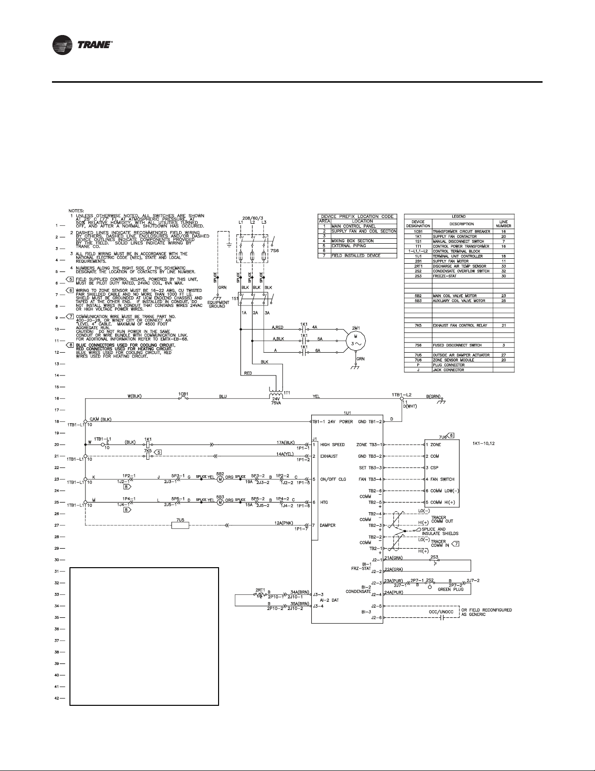
Wiring Diagrams
Four-Pipe BCXC with Tracer ZN510
• 208 volt/3 phase
• 2-position valves
• 2-position damper
• condensate overflow
• low limit protection
• wall-mounted zone sensor
WARNING
Hazardous Voltage!
Disconnect all electric power, including
remote disconnects before servicing. Follow
proper lockout/tagout procedures to ensure
the power can not be inadvertently
energized. Failure to disconnect power before
servicing could result in death or serious
injury.
NOTICE
Use copper conductors only!
Unit terminals are not designed to accept
other conductor types. Failure to use copper
conductors could cause equipment damage.
82 BCXC-SVX01B-EN
Page 83
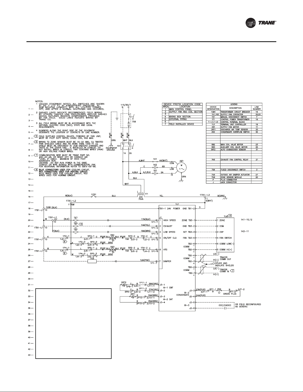
Four-Pipe BCXC with Tracer ZN510
• 115 volt/1 phase
• 2-position valves
• 2-position damper
• 2-speed motor
• condensate overflow
Wiring Diagrams
WARNING
Hazardous Voltage!
Disconnect all electric power, including
remote disconnects before servicing. Follow
proper lockout/tagout procedures to ensure
the power can not be inadvertently
energized. Failure to disconnect power before
servicing could result in death or serious
injury.
NOTICE
Use copper conductors only!
Unit terminals are not designed to accept
other conductor types. Failure to use copper
conductors could cause equipment damage.
BCXC-SVX01B-EN 83
Page 84
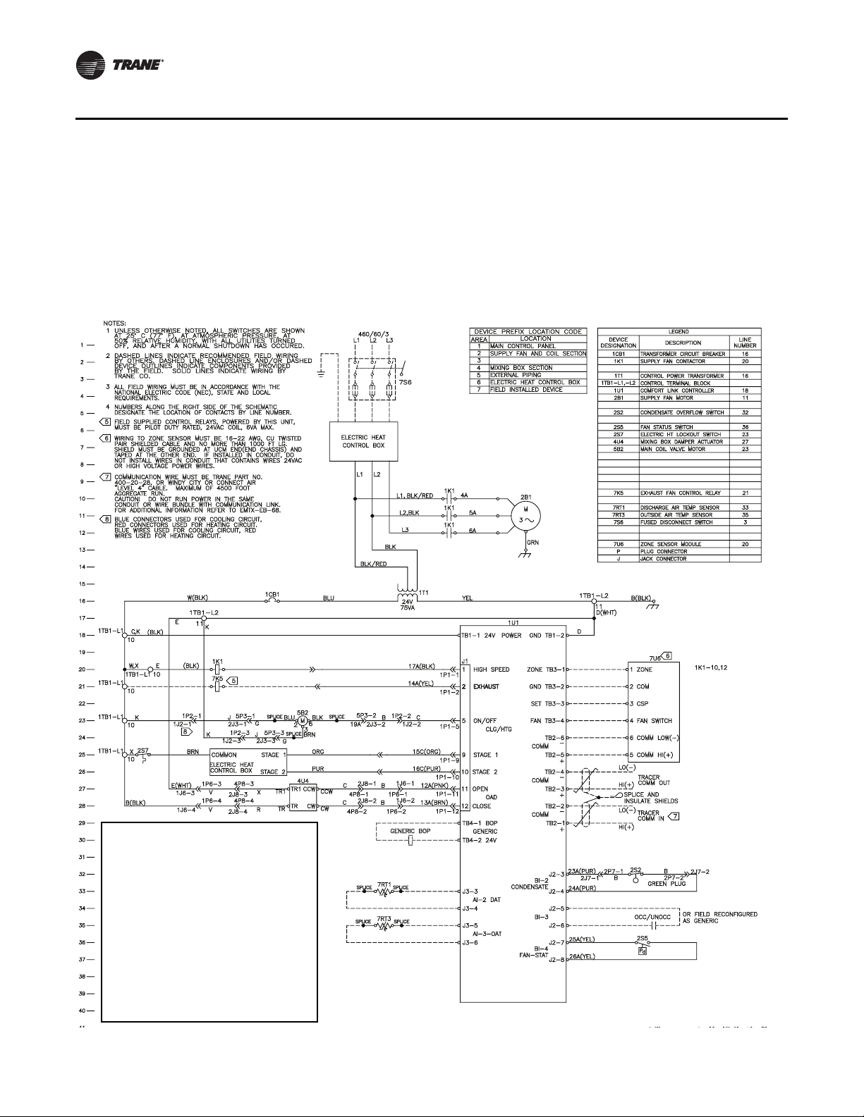
Wiring Diagrams
Two-Pipe BCXC with Tracer ZN520
• 460 volt/3 phase
• 2-position valve
• economizer damper
• 2-stage electric heat
• fan status switch
• condensate overflow
• wall-mounted zone sensor
WARNING
Hazardous Voltage!
Disconnect all electric power, including
remote disconnects before servicing. Follow
proper lockout/tagout procedures to ensure
the power can not be inadvertently
energized. Failure to disconnect power before
servicing could result in death or serious
injury.
NOTICE
Use copper conductors only!
Unit terminals are not designed to accept
other conductor types. Failure to use copper
conductors could cause equipment damage.
84 BCXC-SVX01B-EN
Page 85
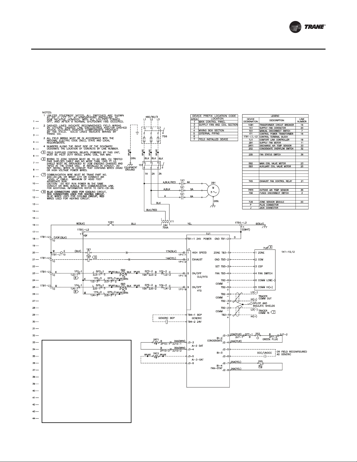
Four-Pipe BCXC with Tracer ZN520
• 460 volt/3 phase
• 2-position valves
• condensate overflow
• fan status switch
Wiring Diagrams
WARNING
Hazardous Voltage!
Disconnect all electric power, including
remote disconnects before servicing. Follow
proper lockout/tagout procedures to ensure
the power can not be inadvertently
energized. Failure to disconnect power before
servicing could result in death or serious
injury.
NOTICE
Use copper conductors only!
Unit terminals are not designed to accept
other conductor types. Failure to use copper
conductors could cause equipment damage.
BCXC-SVX01B-EN 85
Page 86
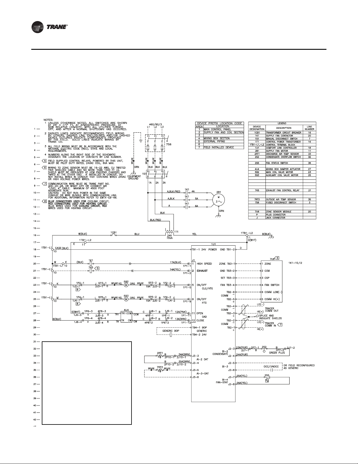
Wiring Diagrams
Four-Pipe BCXC with Tracer ZN520
• 460 volt/3 phase
• economizer damper
• condensate overflow
• fan status switch
• wall-mounted zone sensor
WARNING
Hazardous Voltage!
Disconnect all electric power, including
remote disconnects before servicing. Follow
proper lockout/tagout procedures to ensure
the power can not be inadvertently
energized. Failure to disconnect power before
servicing could result in death or serious
injury.
NOTICE
Use copper conductors only!
Unit terminals are not designed to accept
other conductor types. Failure to use copper
conductors could cause equipment damage.
86 BCXC-SVX01B-EN
Page 87
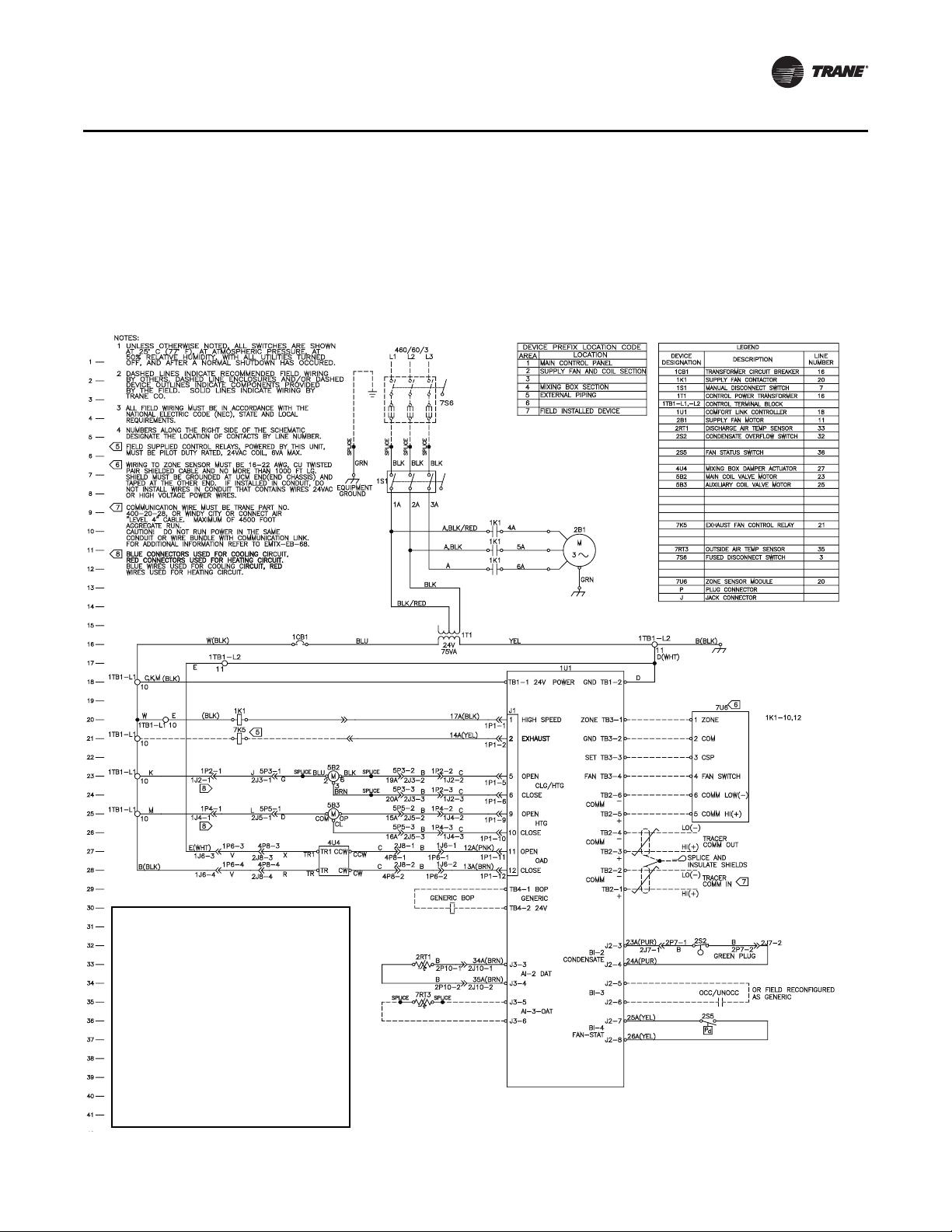
Four-Pipe BCXC with Tracer ZN520
• 460 volt/3 phase
• 3-wire floating point valves
• economizer damper
• condensate overflow
• fan status switch
• wall-mounted zone sensor
Wiring Diagrams
WARNING
Hazardous Voltage!
Disconnect all electric power, including
remote disconnects before servicing. Follow
proper lockout/tagout procedures to ensure
the power can not be inadvertently
energized. Failure to disconnect power before
servicing could result in death or serious
injury.
NOTICE
Use copper conductors only!
Unit terminals are not designed to accept
other conductor types. Failure to use copper
conductors could cause equipment damage.
BCXC-SVX01B-EN 87
Page 88
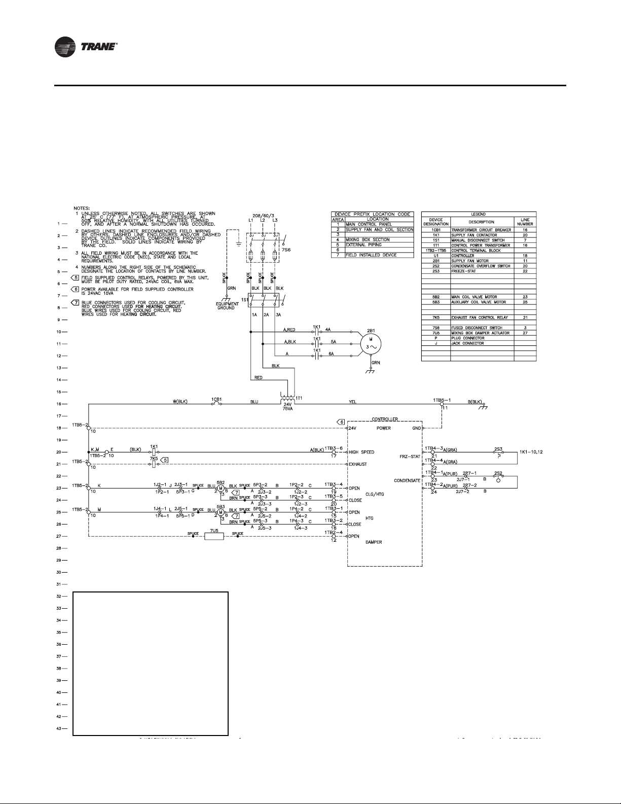
Wiring Diagrams
Four-Pipe BCXC with Control Interface
• • 208 volt/3 phase
• • 3-wire floating point valves
• • 2-position damper
• • low limit protection
• • condensate overflow
WARNING
Hazardous Voltage!
Disconnect all electric power, including
remote disconnects before servicing. Follow
proper lockout/tagout procedures to ensure
the power can not be inadvertently
energized. Failure to disconnect power before
servicing could result in death or serious
injury.
NOTICE
Use copper conductors only!
Unit terminals are not designed to accept
other conductor types. Failure to use copper
conductors could cause equipment damage.
88 BCXC-SVX01B-EN
Page 89
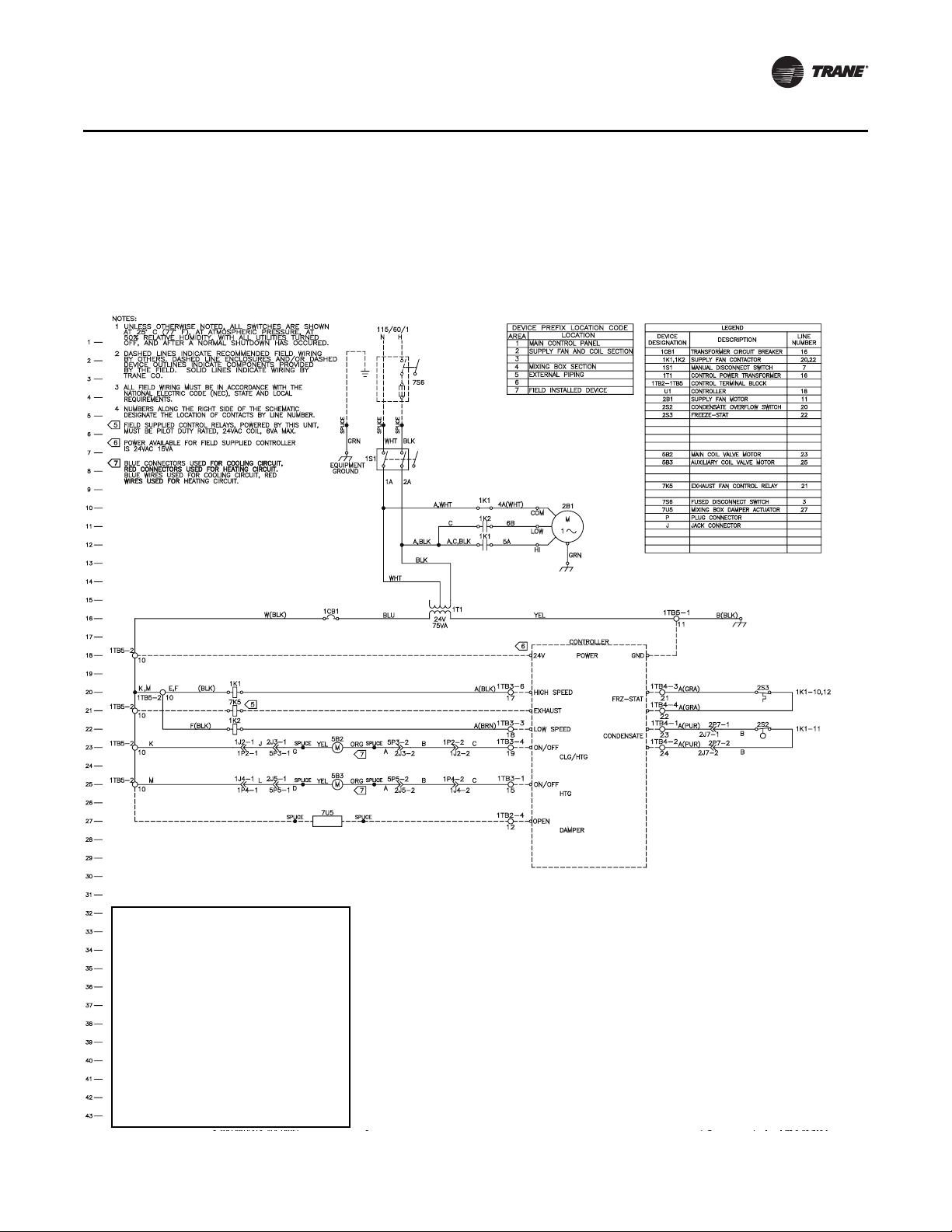
Four-Pipe BCXC with Control Interface
• 115 volt/1 phase
• 2-position damper
• 2-speed motor
• condensate overflow
• low limit protection
Wiring Diagrams
WARNING
Hazardous Voltage!
Disconnect all electric power, including
remote disconnects before servicing. Follow
proper lockout/tagout procedures to ensure
the power can not be inadvertently
energized. Failure to disconnect power before
servicing could result in death or serious
injury.
NOTICE
Use copper conductors only!
Unit terminals are not designed to accept
other conductor types. Failure to use copper
conductors could cause equipment damage.
BCXC-SVX01B-EN 89
Page 90

Wiring Diagrams
5 ON/OFF
CLG
DX COOLING
C
38A
G
,K
K
G,J
DX RELAY
1K3
2S8
EVAP DEFROST FROSTAT
24
24
1K3-23
19B
J
GENERIC BOP
TB4-1 BOP
TB4-2 24V
GENERIC
CONTROL BOX
ELECTRIC HEAT
STAGE 1
BRN
X
ORG
COMMON
,X
9 STAGE 1
15C(ORG)
BLK
WHT
BLK,BLK
WHT,
5A
4A(WHT)
1K1
M
1
2B1
PUR
STAGE 2
10 STAGE 2
16C(PUR)
ELECTRIC HEAT
CONTROL BOX
ELECTRIC HEAT CONTROL BOX
2S7
ELECTRIC HT LOCKOUT SWITCH
23
7RT1
DISCHARGE AIR TEMP SENSOR
33
SPLICE
SPLICE
J3-3
J3-4
AI-2 DAT
COMM HI(+)
COMM LOW(-)
CSP33
FAN SWITCH
5
4
6
COM22
ZONE11
ZONE TB3-1
GND TB3-2
SET TB3-3
FAN TB3-4
TB2-6
-
COMM
TB2-5
+
E(WHT)
B(BLK)
27
MIXING BOX DAMPER ACTUATOR
4U4
CW
4U4
CCW
TR1
CCW
CW
TR1
TR
12 CLOSE
OAD
11 OPEN
13A(BRN)
12A(PNK)
2 EXHAUST
B
B
X
R
E
C
C
V
V
7RT3
OUTSIDE AIR TEMP SENSOR
35
J3-5
AI-3-OAT
J3-6
SPLICE
SPLICE
2S2
CONDENSATE OVERFLOW SWITCH3232
J2-4
J2-3
BI-2
CONDENSATE
23A(PUR)
24A(PUR)
B
B
GREEN PLUG
36
FAN STATUS SWITCH
2S5
J2-7
J2-8
26A(YEL)
25A(YEL)
d
P
BI-4
FAN-STAT
BRN
BRN
277/60/1
N
L1
D(WHT)
B(BLK)
2
1
TRANE CO.
BY THE FIELD. SOLID LINES INDICATE WIRING BY
DEVICE OUTLINES INDICATE COMPONENTS PROVIDED
BY OTHERS. DASHED LINE ENCLOSURES AND/OR DASHED
DASHED LINES INDICATE RECOMMENDED FIELD WIRING
UNLESS OTHERWISE NOTED, ALL SWITCHES ARE SHOWN
OFF, AND AFTER A NORMAL SHUTDOWN HAS OCCURED.
50% RELATIVE HUMIDITY, WITH ALL UTILITIES TURNED
AT 25° C (77° F), AT ATMOSPHERIC PRESSURE, AT
NOTES:
1
2
3
4
5
6
MAIN CONTROL PANEL
SUPPLY FAN AND COIL SECTION
MIXING BOX SECTION
EXTERNAL PIPING
AREA
DEVICE PREFIX LOCATION CODE
1K1
SUPPLY FAN CONTACTOR
ALL FIELD WIRING MUST BE IN ACCORDANCE WITH THE
NATIONAL ELECTRIC CODE (NEC), STATE AND LOCAL
REQUIREMENTS.
3
20
42
41
40
39
38
37
36
35
34
33
32
31
30
29
28
27
26
25
24
23
22
21
20
19
18
17
16
15
14
13
12
11
10
9
8
7
6
5
4
3
2
1
FIELD INSTALLED DEVICE
7
NUMBER
LINE
LEGEND
DESCRIPTION
DESIGNATION
DEVICE
16
CONTROL POWER TRANSFORMER
1T1
CONTROL TERMINAL BLOCK
1TB1-L1,-L2
18
ZN CONTROLLER
1U1
11
SUPPLY FAN MOTOR
2B1
3
FUSED DISCONNECT SWITCH
7S6
20
ZONE SENSOR MODULE
7U6
PLUG CONNECTOR
P
JACK CONNECTOR
J
LOCATION
GRN
YEL
BLU
7K5
EXHAUST FAN CONTROL RELAY
21
OR HIGH VOLTAGE POWER WIRES.
NOT INSTALL WIRES IN CONDUIT THAT CONTAINS WIRES 24VAC
SHIELD MUST BE GROUNDED AT UCM END(END CHASSIS) AND
TAPED AT THE OTHER END. IF INSTALLED IN CONDUIT, DO
PAIR SHIELDED CABLE AND NO MORE THAN 1000 FT LG.
WIRING TO ZONE SENSOR MUST BE 16-22 AWG, CU TWISTED
75VA
BLK
W(BLK)
1CB1
TRANSFORMER CIRCUIT BREAKER1616
OR FIELD RECONFIGURED
AS GENERIC
J2-6
J2-5
OCC/UNOCC
TB1-1 24V
1 HIGH SPEED
J1
TB2-4
COMM
COMM
+
TB2-1
-
TB2-3
TB2-2
+
COMM OUT
INSULATE SHIELDS
COMM IN
TRACER
TRACER
LO(-)
HI(+)
HI(+)
SPLICE AND
LO(-)
D
GND TB1-2
POWER
1U1
BI-3
17A(BLK)
COMMUNICATION WIRE MUST BE TRANE PART NO.
400-20-28, OR WINDY CITY OR CONNECT AIR
AGGREGATE RUN.
"LEVEL 4" CABLE. MAXIMUM OF 4500 FOOT
FOR ADDITIONAL INFORMATION REFER TO EMTX-EB-68.
CAUTION! DO NOT RUN POWER IN THE SAME
CONDUIT OR WIRE BUNDLE WITH COMMUNICATION LINK.
7U6
C
E
W
2 EXHAUST
14A(YEL)
(BLK)
(BLK)
1K1-10,12
DESIGNATE THE LOCATION OF CONTACTS BY LINE NUMBER.
NUMBERS ALONG THE RIGHT SIDE OF THE SCHEMATIC
4
FIELD SUPPLIED CONTROL RELAYS, POWERED BY THIS UNIT,
MUST BE PILOT DUTY RATED, 24VAC COIL, 6VA MAX.
11
1TB1-L2
9
6
1S1
7S6
7S6
7S6
7S6
7S6
7S6
1T1
24V
9
7S6
7S6
2S7
2B1
1
COM
LOW
HI
2B1
3
2B1
1
COM
LOW
HI
2B1
3
1K1
1K2
7
7K5
1K2
1TB1-L11010
1TB1-L1
10
1TB1-L1
10
1TB1-L1
10
1TB1-L1
10
8
8
8
8
8
8
8
8
8
8
8
11
1TB1-L2
5
1K1
1K1
1K1
1K1
1K1
1K1
1K1
1K2
1K1
1K2
1P1-3
1P1-3
2RT1
2P12-1
2J12-1
2P12-2
2J12-2
2J13-1
2P13-1
2S2
2P13-2
2J13-2
2S3
2S5
1K1
1K1
1K1
1K1
1K1
1K1
2J9-4
4P9-4
2J9-3
4P9-3
1P1-11
1P1-12
4P9-2
2J9-2
4P9-1
2J9-1
5P3-2
2J3-2
1P2-2
1J2-2
1J2-1
1P2-1
2J3-1
5P3-1
1P1-5
1P1-5
1P1-6
1J2-1
1P2-1
1P1-5
1J5-1
1P5-1
1P1-9
1P1-10
1P5-3
1J5-3
5P6-3
2J6-3
1P1-9
1J5-1
1P5-1
1P1-9
1J5-1
1P5-1
5RT2
5P10-1
2J10-1
5P10-2
2J10-2
1J2-1
1P2-1
1P1-6
1P1-5
1J2-1
1P2-1
1P1-5
1J5-1
1P5-1
1P1-10
1P1-9
1J5-1
1P5-1
1P1-9
1P1-11
1P1-12
7RT3
7RT1
1CB1
1P1-2
1P1-1
1P1-9
1P1-10
1J8-3
1P8-3
1J8-4
1P8-4
1P8-1
1J8-1
1P8-2
1J8-2
5P3-2
2J3-2
1P2-2
1J2-2
1P2-3
1J2-3
5P3-3
2J3-3
2J3-1
5P3-1
1J2-1
1P2-1
2J6-1
5P6-1
5P6-2
2J6-2
1P5-2
1J5-2
2J6-1
5P6-1
5P6-3
2J6-3
5P6-2
2J6-2
1P5-3
1J5-3
1P5-2
1J5-2
2J6-1
5P6-1
5P6-2
2J6-2
1P5-2
1J5-2
2J3-1
5P3-1
1P2-3
1J2-3
5P3-3
2J3-3
5P3-2
2J3-2
1P2-2
1J2-2
2J6-1
5P6-1
5P6-2
2J6-2
1P5-2
1J5-2
2J3-1
5P3-1
1P2-2
1J2-2
5P3-2
2J3-2
2J3-1
5P3-1
5P3-3
2J3-3
1P2-3
1J2-3
5P3-2
2J3-2
1P2-2
1J2-2
2J6-1
5P6-1
1P5-3
1J5-3
1P5-2
1J5-2
5P6-3
2J6-3
5P6-2
2J6-2
1P11-1
1J11-1
1P11-2
1J11-2
1P1-11
1P1-12
1J8-3
1P8-3
1J8-4
1P8-4
1P8-2
1J8-2
1P8-1
1J8-1
1J8-3
1P8-3
1J8-4
1P8-4
1P8-2
1J8-2
1P8-1
1J8-1
5
6
7
5P4-2
5J4-2
5P7-2
5J7-2
5J4-1
5P4-1
5J7-1
5P7-1
5P4-3
5J4-3
5J4-1
5P4-1
5P4-2
5J4-2
5J4-1
5P4-1
5P4-2
5J4-2
5P4-3
5J4-3
5J4-1
5P4-1
5P4-2
5J4-2
5J4-1
5P4-1
5P4-2
5J4-2
5P4-3
5J4-3
5J7-1
5P7-1
5P7-3
5J7-3
5P7-2
5J7-2
5P7-2
5J7-2
5P7-3
5J7-3
5J7-1
5P7-1
5J7-1
5P7-1
5P7-2
5J7-2
5J7-1
5P7-1
5P7-3
5J7-3
5P7-2
5J7-2
1P1-5
2S8
1K3
3
1K3
4
1P2-2
1J2-2
1J2-1
1P2-1
5
BCXC with DX Coil and Tracer ZN520
NOTES:
1
UNLESS OTHERWISE NOTED, ALL SWITCHES ARE SHOWN
AT 25° C (77° F), AT ATMOSPHERIC PRESSURE, AT
50% RELATIVE HUMIDITY, WITH ALL UTILITIES TURNED
1
OFF, AND AFTER A NORMAL SHUTDOWN HAS OCCURED.
2
DASHED LINES INDICATE RECOMMENDED FIELD WIRING
BY OTHERS. DASHED LINE ENCLOSURES AND/OR DASHED
2
DEVICE OUTLINES INDICATE COMPONENTS PROVIDED
BY THE FIELD. SOLID LINES INDICATE WIRING BY
TRANE CO.
3
3
ALL FIELD WIRING MUST BE IN ACCORDANCE WITH THE
NATIONAL ELECTRIC CODE (NEC), STATE AND LOCAL
4
REQUIREMENTS.
4
NUMBERS ALONG THE RIGHT SIDE OF THE SCHEMATIC
DESIGNATE THE LOCATION OF CONTACTS BY LINE NUMBER.
5
5
FIELD SUPPLIED CONTROL RELAYS, POWERED BY THIS UNIT,
MUST BE PILOT DUTY RATED, 24VAC COIL, 6VA MAX.
6
6
WIRING TO ZONE SENSOR MUST BE 16-22 AWG, CU TWISTED
PAIR SHIELDED CABLE AND NO MORE THAN 1000 FT LG.
7
SHIELD MUST BE GROUNDED AT UCM END(END CHASSIS) AND
TAPED AT THE OTHER END. IF INSTALLED IN CONDUIT, DO
NOT INSTALL WIRES IN CONDUIT THAT CONTAINS WIRES 24VAC
8
OR HIGH VOLTAGE POWER WIRES.
7
COMMUNICATION WIRE MUST BE TRANE PART NO.
9
400-20-28, OR WINDY CITY OR CONNECT AIR
"LEVEL 4" CABLE. MAXIMUM OF 4500 FOOT
AGGREGATE RUN.
10
CAUTION! DO NOT RUN POWER IN THE SAME
CONDUIT OR WIRE BUNDLE WITH COMMUNICATION LINK.
FOR ADDITIONAL INFORMATION REFER TO EMTX-EB-68.
11
8
8
8
88888888888
8
12
9
13
14
15
16
17
1TB1-L1
18
19
20
21
22
23
24
25
26
27
28
29
30
31
32
33
34
35
36
37
38
39
40
41
42
10
1TB1-L1
1TB1-L1
10
1TB1-L1
10
1TB1-L1
10
B(BLK)
WARNING
Hazardous Voltage!
Disconnect all electric power, including
remote disconnects before servicing. Follow
proper lockout/tagout procedures to ensure
the power can not be inadvertently
energized. Failure to disconnect power before
servicing could result in death or serious
injury.
NOTICE
Use copper conductors only!
Unit terminals are not designed to accept
other conductor types. Failure to use copper
conductors could cause equipment damage.
90 BCXC-SVX01B-EN
,K
C
(BLK)
,X
W
K
2S7
X
E
• 277 volt/1 phase
• economizer damper
• condensate overflow
• wall-mounted zone sensor
1CB1
5
5
1K3
5P4-1
5P4-1
5P4-1
5P4-1
5P4-1
5P7-1
5P7-1
5P7-1
5P7-1
5P7-1
X
R
STAGE 1
STAGE 2
5J4-3
5J7-3
224
TR1
TR
5P4-3
5P7-3
G
TR1
TRTRCW
5J4-1
5J4-1
5J4-1
5J4-1
5J4-1
5P3-3
2J3-3
5J7-1
5J7-1
5J7-1
5J7-1
5J7-1
5P6-3
2J6-3
4P9-3
2J9-3
4P9-4
2J9-4
E
1J2-1
1J2-1
1J2-1
1J2-1
1J2-1
1J2-1
1J5-1
1J5-1
1J5-1
1J5-1
1J5-1
E(WHT)
1J8-3
1J8-3
1J8-3
1J8-4
1J8-4
1J8-4
W(BLK)
(BLK)
1P2-1
1P2-1
1P2-1
1P2-1
1P2-1
888
8
8
8
1P2-1
1P5-1
1P5-1
1P5-1
1P5-1
1P5-1
BRN
88888
888
1TB1-L2
11
1K1
7K5
1K2
1K2
5P3-1
5P3-1
5P3-1
5P3-1
5P3-1
DX COOLING
2J3-1
2J3-1
2J3-1
2J3-1
2J3-1
1P2-3
J
1J2-3
5P6-1
5P6-1
5P6-1
5P6-1
5P6-1
COMMON
2J6-1
2J6-1
2J6-1
2J6-1
2J6-1
ELECTRIC HEAT
1P5-3
CONTROL BOX
1J5-3
1P8-3
1P8-3
1P8-3
V
1P8-4
1P8-4
1P8-4
V
4U4
CCW
BLU
G,J
113
ORG
PUR
CCW
CW
1K3
5P4-2
5P4-2
5P4-2
5P4-2
5P4-2
5P4-3
5P4-3
5P7-2
5P7-2
5P7-2
5P7-2
5P7-2
5P7-3
5P7-3
277/60/1
N
ELECTRIC HEAT
CONTROL BOX
1S1
WHT
BRN
5J4-2
5J4-2
5J4-2
5J4-2
5J4-2
38A
5J4-3
5J4-3
5J7-2
5J7-2
5J7-2
5J7-2
5J7-2
5J7-3
5J7-3
2J9-1
C
4P9-1
2J9-2
C
4P9-2
9
5RT2
5P10-1
5P10-2
SPLICE
SPLICE
L1
7S6
7S6
7S6
7S6
7S6
7S6
7S6
7S6
BLK
WHT,
BRN
BLK,BLK
BLK
24V
75VA
17A(BLK)
14A(YEL)
5P3-2
5P3-2
5P3-2
5P3-2
5P3-2
1P2-2
1P2-2
1P2-2
1P2-2
1P2-2
2J3-2
2J3-2
2J3-2
2J3-2
2J3-2
5P3-3
5P3-3
1P2-3
1P2-3
1P2-2
2S8
19B
2J3-3
2J3-3
5P6-2
5P6-2
5P6-2
5P6-2
5P6-2
1P5-2
1P5-2
1P5-2
1P5-2
1P5-2
2J6-2
2J6-2
2J6-2
2J6-2
2J6-2
5P6-3
5P6-3
1P5-3
1P5-3
2J6-3
2J6-3
1J8-1
1J8-1
1J8-1
B
1P8-1
1P8-1
1P8-1
1J8-2
1J8-2
1J8-2
B
1P8-2
1P8-2
1P8-2
GENERIC BOP
1P11-1
2J10-1
1P11-2
2J10-2
2RT1
7RT1
SPLICE
2P12-1
2P12-2
7RT3
SPLICE
DEVICE PREFIX LOCATION CODE
AREA
1
2
3
4
5
6
7
1K1
1K1
1K1
1K1
1K1
4A(WHT)
1K2
1K2
1K1
1K1
1K1
1K1
1K1
1K1
1K1
1K1
1K1
1K1
5A
1T1
YEL
TB1-1 24V
J1
1 HIGH SPEED
1P1-1
2 EXHAUST
2 EXHAUST
1P1-2
1P1-3
1P1-3
1J2-2
1J2-2
1J2-2
1J2-2
1J2-2
1J2-3
1J2-3
15C(ORG)
1J5-2
1J5-2
1J5-2
1J5-2
1J5-2
16C(PUR)
1J5-3
1J5-3
1J2-2
12A(PNK)
13A(BRN)
1J11-1
1J11-2
2J12-1
2J12-2
1P1-5
1P1-5
1P1-5
1P1-5
1P1-5
C
1P1-6
1P1-6
1P1-5
1P1-9
1P1-9
1P1-9
1P1-9
1P1-9
1P1-9
1P1-10
1P1-10
1P1-10
1P1-11
1P1-11
1P1-11
1P1-12
1P1-12
1P1-12
5 ON/OFF
9 STAGE 1
10 STAGE 2
11 OPEN
12 CLOSE
TB4-1 BOP
GENERIC
TB4-2 24V
J3-3
AI-2 DAT
J3-4
J3-5
AI-3-OAT
J3-6
LOCATION
MAIN CONTROL PANEL
SUPPLY FAN AND COIL SECTION
MIXING BOX SECTION
EXTERNAL PIPING
ELECTRIC HEAT CONTROL BOX
FIELD INSTALLED DEVICE
2B1
2B1
2B1
2B1
2B1
COM
COM
LOW
LOW
HI
HI
1U1
POWER
M
1
3
1
3
1
GRN
GND TB1-2
ZONE TB3-1
GND TB3-2
SET TB3-3
FAN TB3-4
CLG
OAD
COMM
COMM
COMM
BI-2
CONDENSATE
BI-3
BI-4
FAN -STAT
TB2-6
TB2-5
TB2-4
TB2-3
TB2-2
TB2-1
J2-3
J2-4
J2-5
J2-6
J2-7
J2-8
DEVICE
DESIGNATION
1CB1
TRANSFORMER CIRCUIT BREAKER
1K1
SUPPLY FAN CONTACTOR
DX RELAY
1K3
CONTROL POWER TRANSFORMER
1T1
1TB1-L1,-L2
CONTROL TERMINAL BLOCK
ZN CONTROLLER
1U1
SUPPLY FAN MOTOR
2B1
2S2
1TB1-L2
11
D(WHT)
D
CONDENSATE OVERFLOW SWITCH
FAN STATUS SWITCH
2S5
2S7
ELECTRIC HT LOCKOUT SWITCH
2S8
EVAP DEFROST FROSTAT
MIXING BOX DAMPER ACTUATOR
4U4
7K5
EXHAUST FAN CONTROL RELAY
7RT1
DISCHARGE AIR TEMP SENSOR
7RT3
OUTSIDE AIR TEMP SENSOR
FUSED DISCONNECT SWITCH
7S6
ZONE SENSOR MODULE
7U6
PLUG CONNECTOR
P
JACK CONNECTOR
J
B(BLK)
ZONE
COM
CSP
FAN SWITCH
4
COMM LOW(-)
LO(-)
HI(+)
SPLICE AND
INSULATE SHIELDS
LO(-)
HI(+)
2P13-1
B
6
COMM HI(+)
5
TRACER
COMM OUT
TRACER
COMM IN
2S3
2S2
OCC/UNOCC
2S5
P
-
+
-
+
-
+
23A(PUR)
24A(PUR)
25A(YEL)
26A(YEL)
2J13-1
7U6
GREEN PLUG
d
LEGEND
DESCRIPTION
6
7
B
2P13-2
OR FIELD RECONFIGURED
AS GENERIC
1K1-10,12
1K3-23
2J13-2
LINE
NUMBER
20
24
16
18
11
36
23
24
27
21
33
35
20
3
Page 91

BCXC with DX Coil, Hydronic Heating, and Tracer ZN520
5 ON/OFF
CLG
DX COOLING
C
38A
G
,K
K
G,J
DX RELAY
1K3
2S8
EVAP DEFROST FROSTAT
24
24
1K3-23
19B
J
CW
CCW
7U4
TR1
TR
12A(PNK)
13A(BRN)
12 CLOSE
11 OPEN
OAD
7U4
MIXING BOX DAMPER ACTUATOR2727
E(WHT)
B(BLK)
SPLICE
SPLICE
SPLICE
SPLICE
E
GENERIC BOP
TB4-1 BOP
TB4-2 24V
GENERIC
7
MANUAL DISCONNECT SWITCH
1S1
EQUIPMENT
GROUND
2A
1A
GRN
SPLICE
BLK
SPLICE
SPLICE
7B3
M
7B3
HEATING COIL VALVE MOTOR
25
(7VA MAX)
9 ON/OFF
HTG
M
BLUE CONNECTORS USED FOR COOLING CIRCUIT,
RED CONNECTORS USED FOR HEATING CIRCUIT.
BLUE WIRES USED FOR COOLING CIRCUIT, RED
WIRES USED FOR HEATING CIRCUIT.
,M
D
L
15A
B
C
COMM HI(+)
COMM LOW(-)
CSP33
FAN SWITCH
5
4
6
COM22
ZONE11
ZONE TB3-1
GND TB3-2
SET TB3-3
FAN TB3-4
TB2-6
-
COMM
TB2-5
+
BLK/RED
BLK/RED
460/60/3
A,BLK
A
A,
3A
BLK
SPLICE
BLK
6A
5A
4A
L1
L2
L3
M
33
DISCHARGE AIR TEMP SENSOR
2RT1
J3-3
AI-2 DAT
J3-4
34A(BRN)
35A(BRN)
B
B
7RT3
OUTSIDE AIR TEMP SENSOR
35
J3-5
AI-3-OAT
J3-6
SPLICE
SPLICE
2S2
CONDENSATE OVERFLOW SWITCH3232
J2-4
J2-3
BI-2
CONDENSATE
23A(PUR)
24A(PUR)
B
B
GREEN PLUG
30
FREEZE-STAT
2S3
BI-1
J2-1
J2-2
FRZ-STAT
21A(GRA)
22A(GRA)
D(WHT)
B(BLK)
2
1
TRANE CO.
BY THE FIELD. SOLID LINES INDICATE WIRING BY
DEVICE OUTLINES INDICATE COMPONENTS PROVIDED
BY OTHERS. DASHED LINE ENCLOSURES AND/OR DASHED
DASHED LINES INDICATE RECOMMENDED FIELD WIRING
UNLESS OTHERWISE NOTED, ALL SWITCHES ARE SHOWN
OFF, AND AFTER A NORMAL SHUTDOWN HAS OCCURED.
50% RELATIVE HUMIDITY, WITH ALL UTILITIES TURNED
AT 25˚˚
C (77˚˚
F), AT ATMOSPHERIC PRESSURE, AT
NOTES:
1
2
3
4
5
6
MAIN CONTROL PANEL
SUPPLY FAN AND COIL SECTION
MIXING BOX SECTION
EXTERNAL PIPING
AREA
DEVICE PREFIX LOCATION CODE
1K1
SUPPLY FAN CONTACTOR
ALL FIELD WIRING MUST BE IN ACCORDANCE WITH THE
NATIONAL ELECTRIC CODE (NEC), STATE AND LOCAL
REQUIREMENTS.
3
20
42
41
40
39
38
37
36
35
34
33
32
31
30
29
28
27
26
25
24
23
22
21
20
19
18
17
16
15
14
13
12
11
10
9
8
7
6
5
4
3
2
1
FIELD INSTALLED DEVICE
7
NUMBER
LINE
LEGEND
DESCRIPTION
DESIGNATION
DEVICE
16
CONTROL POWER TRANSFORMER
1T1
CONTROL TERMINAL BLOCK
1TB1-L1,-L2
18
ZN CONTROLLER
1U1
11
SUPPLY FAN MOTOR
2B1
3
FUSED DISCONNECT SWITCH
7S6
20
ZONE SENSOR MODULE
7U6
PLUG CONNECTOR
P
JACK CONNECTOR
J
LOCATION
GRN
YEL
BLU
7K5
EXHAUST FAN CONTROL RELAY
21
OR HIGH VOLTAGE POWER WIRES.
NOT INSTALL WIRES IN CONDUIT THAT CONTAINS WIRES 24VAC
SHIELD MUST BE GROUNDED AT UCM END(END CHASSIS) AND
TAPED AT THE OTHER END. IF INSTALLED IN CONDUIT, DO
PAIR SHIELDED CABLE AND NO MORE THAN 1000 FT LG.
WIRING TO ZONE SENSOR MUST BE 16-22 AWG, CU TWISTED
75VA
BLK
W(BLK)
1CB1
TRANSFORMER CIRCUIT BREAKER1616
OR FIELD RECONFIGURED
AS GENERIC
J2-6
J2-5
OCC/UNOCC
TB1-1 24V
1 HIGH SPEED
J1
TB2-4
COMM
COMM
+
TB2-1
-
TB2-3
TB2-2
+
COMM OUT
INSULATE SHIELDS
COMM IN
TRACER
TRACER
LO(-)
HI(+)
HI(+)
SPLICE AND
LO(-)
D
GND TB1-2
POWER
1U1
BI-3
17A(BLK)
COMMUNICATION WIRE MUST BE TRANE PART NO.
400-20-28, OR WINDY CITY OR CONNECT AIR
AGGREGATE RUN.
"LEVEL 4" CABLE. MAXIMUM OF 4500 FOOT
FOR ADDITIONAL INFORMATION REFER TO EMTX-EB-68.
CAUTION! DO NOT RUN POWER IN THE SAME
CONDUIT OR WIRE BUNDLE WITH COMMUNICATION LINK.
7U6
C
E
W
2 EXHAUST
14A(YEL)
(BLK)
(BLK)
1K1-10,12
DESIGNATE THE LOCATION OF CONTACTS BY LINE NUMBER.
NUMBERS ALONG THE RIGHT SIDE OF THE SCHEMATIC
4
FIELD SUPPLIED CONTROL RELAYS, POWERED BY THIS UNIT,
MUST BE PILOT DUTY RATED, 24VAC COIL, 6VA MAX.
11
1TB1-L2
9
6
1S1
7S6
7S6
7S6
7S6
7S6
7S6
1T1
24V
9
7S6
7S6
2S7
2B1
1
COM
LOW
HI
2B1
3
2B1
1
COM
LOW
HI
2B1
3
1K1
1K2
7
7K5
1K2
1TB1-L11010
1TB1-L1
10
1TB1-L1
10
1TB1-L1
10
1TB1-L1
10
8
8
8
8
8
8
8
8
8
8
8
11
1TB1-L2
5
1K1
1K1
1K1
1K1
1K1
1K1
1K1
1K2
1K1
1K2
1P1-3
1P1-3
2RT1
2P12-1
2J12-1
2P12-2
2J12-2
2J13-1
2P13-1
2S2
2P13-2
2J13-2
2S3
2S5
1K1
1K1
1K1
1K1
1K1
1K1
2J9-4
4P9-4
2J9-3
4P9-3
1P1-11
1P1-12
4P9-2
2J9-2
4P9-1
2J9-1
5P3-2
2J3-2
1P2-2
1J2-2
1J2-1
1P2-1
2J3-1
5P3-1
1P1-5
1P1-5
1P1-6
1J2-1
1P2-1
1P1-5
1J5-1
1P5-1
1P1-9
1P1-10
1P5-3
1J5-3
5P6-3
2J6-3
1P1-9
1J5-1
1P5-1
1P1-9
1J5-1
1P5-1
5RT2
5P10-1
2J10-1
5P10-2
2J10-2
1J2-1
1P2-1
1P1-6
1P1-5
1J2-1
1P2-1
1P1-5
1J5-1
1P5-1
1P1-10
1P1-9
1J5-1
1P5-1
1P1-9
1P1-11
1P1-12
7RT3
7RT1
1CB1
1P1-2
1P1-1
1P1-9
1P1-10
1J8-3
1P8-3
1J8-4
1P8-4
1P8-1
1J8-1
1P8-2
1J8-2
5P3-2
2J3-2
1P2-2
1J2-2
1P2-3
1J2-3
5P3-3
2J3-3
2J3-1
5P3-1
1J2-1
1P2-1
2J6-1
5P6-1
5P6-2
2J6-2
1P5-2
1J5-2
2J6-1
5P6-1
5P6-3
2J6-3
5P6-2
2J6-2
1P5-3
1J5-3
1P5-2
1J5-2
2J6-1
5P6-1
5P6-2
2J6-2
1P5-2
1J5-2
2J3-1
5P3-1
1P2-3
1J2-3
5P3-3
2J3-3
5P3-2
2J3-2
1P2-2
1J2-2
2J6-1
5P6-1
5P6-2
2J6-2
1P5-2
1J5-2
2J3-1
5P3-1
1P2-2
1J2-2
5P3-2
2J3-2
2J3-1
5P3-1
5P3-3
2J3-3
1P2-3
1J2-3
5P3-2
2J3-2
1P2-2
1J2-2
2J6-1
5P6-1
1P5-3
1J5-3
1P5-2
1J5-2
5P6-3
2J6-3
5P6-2
2J6-2
1P11-1
1J11-1
1P11-2
1J11-2
1P1-11
1P1-12
1J8-3
1P8-3
1J8-4
1P8-4
1P8-2
1J8-2
1P8-1
1J8-1
1J8-3
1P8-3
1J8-4
1P8-4
1P8-2
1J8-2
1P8-1
1J8-1
5
6
7
5P4-2
5J4-2
5P7-2
5J7-2
5J4-1
5P4-1
5J7-1
5P7-1
5P4-3
5J4-3
5J4-1
5P4-1
5P4-2
5J4-2
5J4-1
5P4-1
5P4-2
5J4-2
5P4-3
5J4-3
5J4-1
5P4-1
5P4-2
5J4-2
5J4-1
5P4-1
5P4-2
5J4-2
5P4-3
5J4-3
5J7-1
5P7-1
5P7-3
5J7-3
5P7-2
5J7-2
5P7-2
5J7-2
5P7-3
5J7-3
5J7-1
5P7-1
5J7-1
5P7-1
5P7-2
5J7-2
5J7-1
5P7-1
5P7-3
5J7-3
5P7-2
5J7-2
1P1-5
2S8
1K3
3
1K3
4
1P2-2
1J2-2
1J2-1
1P2-1
5
NOTES:
1
UNLESS OTHERWISE NOTED, ALL SWITCHES ARE SHOWN
AT 25
50% RELATIVE HUMIDITY, WITH ALL UTILITIES TURNED
1
OFF, AND AFTER A NORMAL SHUTDOWN HAS OCCURED.
2
DASHED LINES INDICATE RECOMMENDED FIELD WIRING
BY OTHERS. DASHED LINE ENCLOSURES AND/OR DASHED
2
DEVICE OUTLINES INDICATE COMPONENTS PROVIDED
BY THE FIELD. SOLID LINES INDICATE WIRING BY
TRANE CO.
3
3
ALL FIELD WIRING MUST BE IN ACCORDANCE WITH THE
NATIONAL ELECTRIC CODE (NEC), STATE AND LOCAL
4
REQUIREMENTS.
4
BCXC-SVX01B-EN 91
NUMBERS ALONG THE RIGHT SIDE OF THE SCHEMATIC
DESIGNATE THE LOCATION OF CONTACTS BY LINE NUMBER.
5
5
FIELD SUPPLIED CONTROL RELAYS, POWERED BY THIS UNIT,
MUST BE PILOT DUTY RATED, 24VAC COIL, 6VA MAX.
6
6
WIRING TO ZONE SENSOR MUST BE 16-22 AWG, CU TWISTED
PAIR SHIELDED CABLE AND NO MORE THAN 1000 FT LG.
7
SHIELD MUST BE GROUNDED AT UCM END(END CHASSIS) AND
TAPED AT THE OTHER END. IF INSTALLED IN CONDUIT, DO
NOT INSTALL WIRES IN CONDUIT THAT CONTAINS WIRES 24VAC
8
OR HIGH VOLTAGE POWER WIRES.
7
COMMUNICATION WIRE MUST BE TRANE PART NO.
9
400-20-28, OR WINDY CITY OR CONNECT AIR
"LEVEL 4" CABLE. MAXIMUM OF 4500 FOOT
AGGREGATE RUN.
10
CAUTION! DO NOT RUN POWER IN THE SAME
CONDUIT OR WIRE BUNDLE WITH COMMUNICATION LINK.
FOR ADDITIONAL INFORMATION REFER TO EMTX-EB-68.
11
8
8
8
88888888888
8
BLUE CONNECTORS USED FOR COOLING CIRCUIT,
RED CONNECTORS USED FOR HEATING CIRCUIT.
BLUE WIRES USED FOR COOLING CIRCUIT, RED
12
WIRES USED FOR HEATING CIRCUIT.
9
13
14
15
16
17
1TB1-L1
18
19
20
21
22
23
24
25
26
27
28
29
30
31
32
33
34
35
36
37
38
39
40
41
42
10
1TB1-L1
1TB1-L1
10
1TB1-L1
10
1TB1-L1
10
B(BLK)
WARNING
Hazardous Voltage!
Disconnect all electric power, including
remote disconnects before servicing. Follow
proper lockout/tagout procedures to ensure
the power can not be inadvertently
energized. Failure to disconnect power before
servicing could result in death or serious
injury.
NOTICE
Use copper conductors only!
Unit terminals are not designed to accept
other conductor types. Failure to use copper
conductors could cause equipment damage.
C (77
F), AT ATMOSPHERIC PRESSURE, AT
W(BLK)
1TB1-L2
E
,K
C
,M
(BLK)
E
W
K
2S7
M
1J2-1
1J2-1
1J2-1
1J2-1
1J2-1
1J2-1
1J5-1
1J5-1
1J5-1
1J5-1
1J5-1
E(WHT)
1J8-3
1J8-3
1J8-3
1J8-4
1J8-4
1J8-4
(BLK)
1P2-1
1P2-1
1P2-1
1P2-1
1P2-1
888
8
8
8
1P2-1
1P5-1
1P5-1
1P5-1
1P5-1
1P5-1
88888
888
• 460 volt/3 phase
• economizer damper
• condensate overflow
• wall-mounted zone sensor
SPLICE
GRN
1S1
EQUIPMENT
GROUND
5J4-3
5J7-3
1K3
224
5P4-3
5P7-3
7B3
TR1
TR
G
G,J
(7VA MAX)
M
7U4
CCW
CW
BLU
5P4-2
5P4-2
5P4-2
5P4-2
5P4-2
1K3
5P4-3
5P4-3
113
5P7-2
5P7-2
5P7-2
5P7-2
5P7-2
5P7-3
5P7-3
5J4-2
5J4-2
5J4-2
5J4-2
5J4-2
5J4-3
5J4-3
5J7-2
5J7-2
5J7-2
5J7-2
5J7-2
5J7-3
5J7-3
9
38A
4P9-1
4P9-2
11
1P8-3
1P8-3
1P8-3
1P8-4
1P8-4
1P8-4
1K1
7K5
1K2
1K2
5P3-1
5P3-1
5P3-1
5P3-1
5P3-1
DX COOLING
2J3-1
2J3-1
2J3-1
2J3-1
2J3-1
1P2-3
J
1J2-3
5P6-1
5P6-1
5P6-1
5P6-1
5P6-1
L
2J6-1
2J6-1
2J6-1
2J6-1
2J6-1
1P5-3
1J5-3
5
4P9-3
2J9-3
4P9-4
2J9-4
1CB1
5
5P4-1
5P4-1
5P4-1
5P4-1
5P4-1
5J4-1
5J4-1
5J4-1
5J4-1
5J4-1
5P3-3
2J3-3
5P7-1
5P7-1
5P7-1
5P7-1
5P7-1
D
5J7-1
5J7-1
5J7-1
5J7-1
5J7-1
5P6-3
2J6-3
SPLICE
SPLICE
L1
SPLICE
BLK
1A
15A
SPLICE
SPLICE
5RT2
5P10-2
SPLICE
460/60/3
BLK/RED
5P3-2
5P3-2
5P3-2
5P3-2
5P3-2
5P3-3
5P3-3
2S8
5P6-2
5P6-2
5P6-2
5P6-2
5P6-2
5P6-3
5P6-3
2J9-1
2J9-2
5P10-1
L2
L3
7S6
7S6
7S6
7S6
7S6
7S6
7S6
7S6
SPLICE
SPLICE
BLK
BLK
2A
3A
BLK/RED
A,
A,BLK
A
BLK
1T1
24V
75VA
17A(BLK)
14A(YEL)
1P2-2
1P2-2
1P2-2
1P2-2
1P2-2
1J2-2
1J2-2
1J2-2
1J2-2
1J2-2
2J3-2
2J3-2
2J3-2
2J3-2
2J3-2
1P2-3
1P2-3
1P2-2
19B
1J2-3
1J2-3
2J3-3
2J3-3
2J6-2
2J6-2
2J6-2
2J6-2
2J6-2
2J6-3
2J6-3
B
1P8-1
1P8-1
1P8-1
1P8-2
1P8-2
1P8-2
GENERIC BOP
2J10-1
2J10-2
2RT1
7RT1
7RT3
1J8-1
1J8-1
1J8-1
1J8-2
1J8-2
1J8-2
1P11-2
B
2P12-1
B
2P12-2
SPLICE
1P5-2
1P5-2
1P5-2
1P5-2
1P5-2
1P5-3
1P5-3
1P11-1
1J5-2
1J5-2
1J5-2
1J5-2
1J5-2
1J5-3
1J5-3
1J2-2
12A(PNK)
13A(BRN)
C
1P1-10
1P1-10
1P1-10
1P1-11
1P1-11
1P1-11
1P1-12
1P1-12
1P1-12
1J11-1
1J11-2
34A(BRN)
2J12-1
35A(BRN)
2J12-2
DEVICE PREFIX LOCATION CODE
AREA
1K1
1K1
1K1
1K1
4A
1K2
1K2
1K1
1K1
5A
1K1
1K1
1K1
1K1
1K1
1K1
1K1
1K1
6A
YEL
TB1-1 24V
J1
1 HIGH SPEED
1P1-1
2 EXHAUST
1P1-2
1P1-3
1P1-3
1P1-5
1P1-5
1P1-5
1P1-5
1P1-5
C
5 ON/OFF
1P1-6
1P1-6
1P1-5
9 ON/OFF
1P1-9
1P1-9
1P1-9
1P1-9
1P1-9
1P1-9
11 OPEN
12 CLOSE
TB4-1 BOP
GENERIC
TB4-2 24V
J3-3
AI-2 DAT
J3-4
J3-5
AI-3-OAT
J3-6
LOCATION
MAIN CONTROL PANEL
1
2
SUPPLY FAN AND COIL SECTION
3
MIXING BOX SECTION
4
EXTERNAL PIPING
5
6
7
FIELD INSTALLED DEVICE
2B1
2B1
2B1
2B1
COM
COM
M
1
3
1
3
LOW
LOW
HI
HI
GRN
1U1
GND TB1-2
POWER
ZONE TB3-1
GND TB3-2
SET TB3-3
FAN TB3-4
CLG
COMM
HTG
COMM
OAD
COMM
FRZ-STAT
CONDENSATE
1TB1-L2
11
D(WHT)
D
TB2-6
-
TB2-5
+
TB2-4
-
TB2-3
+
TB2-2
-
TB2-1
+
21A(GRA)
J2-1
BI-1
22A(GRA)
J2-2
23A(PUR)
J2-3
24A(PUR)
J2-4
J2-5
J2-6
2J13-1
BI-2
BI-3
DEVICE
DESIGNATION
1CB1
TRANSFORMER CIRCUIT BREAKER
1K1
SUPPLY FAN CONTACTOR
DX RELAY
1K3
MANUAL DISCONNECT SWITCH
1S1
CONTROL POWER TRANSFORMER
1T1
1TB1-L1,-L2
CONTROL TERMINAL BLOCK
ZN CONTROLLER
1U1
SUPPLY FAN MOTOR
2B1
DISCHARGE AIR TEMP SENSOR
2RT1
2S2
CONDENSATE OVERFLOW SWITCH
FREEZE-STAT
2S3
2S8
EVAP DEFROST FROSTAT
7B3
HEATING COIL VALVE MOTOR
7K5
EXHAUST FAN CONTROL RELAY
7RT3
OUTSIDE AIR TEMP SENSOR
FUSED DISCONNECT SWITCH
7S6
7U4
MIXING BOX DAMPER ACTUATOR
ZONE SENSOR MODULE
7U6
PLUG CONNECTOR
P
JACK CONNECTOR
J
B(BLK)
ZONE
COM
CSP
FAN SWITCH
4
COMM LOW(-)
6
COMM HI(+)
5
LO(-)
TRACER
COMM OUT
HI(+)
SPLICE AND
INSULATE SHIELDS
LO(-)
TRACER
COMM IN
HI(+)
2S3
2S2
2P13-1
B
OCC/UNOCC
2S5
Wiring Diagrams
LEGEND
DESCRIPTION
6
7U6
B
2P13-2
GREEN PLUG
1K1-10,12
1K3-23
7
2J13-2
OR FIELD RECONFIGURED
AS GENERIC
LINE
NUMBER
20
24
16
18
11
33
30
24
25
21
35
20
7
3
Page 92

www.trane.com
For more information, contact your local Trane
office or e-mail us at comfort@trane.com
Literature Order Number BCXC-SVX01B-EN
Date April 2008
Supersedes BCXC-SVX01A-EN September 2002
Trane has a policy of continuous product and product data improvement and reserves the right to
change design and specifications without notice.
 Loading...