

Page 1
HAZARDOUS VOLTAGE - DISCONNECT POWER BEFORE SERVICING
WARNING:
Installer’s Guide
18-GJ11D1-2
Ultraviolet (UV-C) Lamp Kit for
2-5 Ton Air Handlers
ALL phases of this installation must comply with NATIONAL, STATE AND LOCAL CODES
IMPORTANT — This Document is customer property and is to remain with this unit. Please return to service
information pack upon completion of work.
Models:
BAYUVCLK001 - 40 Watt, 2 Lamp
NOTE: A BAYCC24VK01 can be installed for Series 8 Air Handlers
to extend the life of the lamp. This accessory kit will disable the
lamp during the heating season (kit is purchased separately).
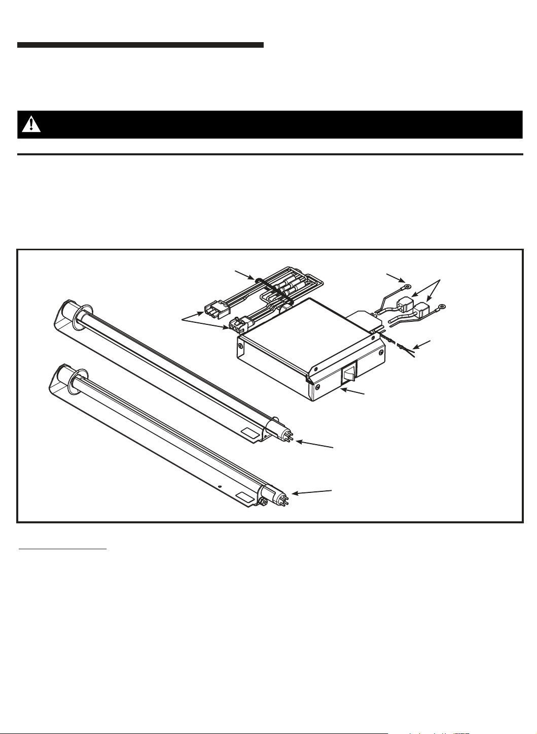
Cable Tie -
Do NOT Cut
or Remove
Power
Supply
Plugs
Used with:
Series 2/4/5/7/8 Air Handlers
Note: 200-230V Units Only
Lamp Bracket
Grounds
3.) Ballast and Control Assembly with
Door Switch and Wiring Harness
2.) Left Side UV Lamp and Bracket Assembly
Lamp Connector
UV Lamp
Control Leads
Kit Contents (Items 4-10 are not pictured)
Item Qty Description
1 1 Right Side UV Lamp and Bracket Assembly
2 1 Left Side UV Lamp and Bracket Assembly
3 1 Ballast and Control Assembly with door switch
and wiring harness (rated 200-230 VAC, 50-60 Hz)
4 4 Cable Tie
5 2 Wire Nut
6 2 Screw
7 3 Isopropyl alcohol swab
8 1 Wiring Diagram
9 1 UV Warning Label
10 4 8-32 Hex nut with star washer
Field Supplied
Ammeter with the ability to measure milliamps
© 2010 Trane
1.) Right Side UV Lamp and Bracket Assembly
General
The United States Environmental Protection Agency (EPA)
believes that molds and bacteria inside buildings have the
potential to cause health problems in sensitive individuals.
The manufacturer provides high intensity C-band ultraviolet
radiation (UV-C lamp kits) for installation in air handlers for the
purpose of reducing microbiological growth (mold and bacteria) within the equipment. Polymer materials that are susceptible to deterioration by the UV-C lamp shall be shielded from
direct exposure to the light. This kit was designed with this
consideration and the reflectors must be in place. In addition,
UV-C radiation can damage human tissue, namely eyes and
skin. To reduce the potential for inadvertent exposure to the
lights by operating and maintenance personnel, an electrical
interlock that automatically disconnects power to the lamp is
provided integral to the ballast assembly.
Page 2
▲
CAUTION
!
▲
WARNING
!
▲
WARNING
!
▲
WARNING
!
▲
WARNING
!
▲
CAUTION
!
▲
WARNING
!
Safety Information
SAFETY HAZARD! This information is for use by individu-
als having adequate backgrounds of electrical and mechanical
experience. Any attempt to repair a central air conditioning
product may result in personal injury and/or property damage. The manufacturer or seller cannot be responsible for the
interpretation of this information, nor can it assume any liability
in connection with its use.
PERSONAL INJURY HAZARD! Disconnect input
power before beginning installation. Professional installation
required per NEC standards. The power supply to this ultraviolet appliance must be disconnected before opening or servicing
the unit. Any access panels or doors, within sight of the UV
lamps, must be interlocked so as to disconnect power to the
UV appliance upon opening or removal.
HAZARDOUS VOLTAGE AND EXPOSURE TO
ULTRAVIOLET RADIATION! This product contains
components that emit high-intensity ultraviolet (UV-C) radiation
which can be harmful to unprotected eyes and skin. Disconnect
all electrical power, including remote disconnects, before servicing. Follow proper lockout/tagout procedures to ensure the
power can not be inadvertently energized. Failure to disconnect
power before servicing could result in death or serious injury.
HAZARDOUS VOLTAGE! Multiple power sources may
be present. Disconnect all electrical power, including remote
disconnects, before servicing. Follow proper lockout/tagout
procedures to ensure the power can not be inadvertently energized. Failure to disconnect power before servicing could result
in death or serious injury.
HAZARDOUS VAPORS! If UV bulbs are broken, an ap-
propriate respirator should be considered to prevent inhalation
of mercury vapors. Failure to use a respirator could result in
death or serious injury.
LAMPS CONTAIN MERCURY! Follow local and state
guidelines for disposal of mercury bulbs.
BROKEN GLASS! Bulbs are fragile and can be easily
broken. Always use gloves and eye protection when handling
these bulbs. Failure to handle bulbs properly may result in
minor to moderate injury.
IMPORTANT - Avoid touching the lamp with bare hands as skin oils can accelerate future glass soiling and degrade the lamp performance. Wipe the lamp
with a clean cloth and rubbing alcohol or glass cleaner after handling.
2
18-GJ11D1-2
Page 3
Pre-installation Instructions
▲
WARNING
!
1. Read all instructions before installing UV lamp kit.
2. Avoid touching the lamp with bare hands as skin oils can accelerate future glass soiling and degrade the lamp performance.
Wipe the lamp with a clean cloth and rubbing alcohol or glass
cleaner after handling.
2. Disconnect all power to the air handler.
HAZARDOUS VOLTAGE! Multiple power sources
may be present. Disconnect all electrical power, including
remote disconnects, before servicing. Follow proper lockout/
tagout procedures to ensure the power can not be inadvertently energized. Failure to disconnect power before servicing could result in death or serious injury.
IMPORTANT: The Right side lamp bracket must be installed before
installing the ballast assembly.
IMPORTANT: The lamp brackets and the ballast assembly are provided
with aggressive adhesive on back. The adhesive has a peel-off liner.
Do not remove the liner until these items have been placed into unit and
proper mounting locations within the unit have been confirmed.
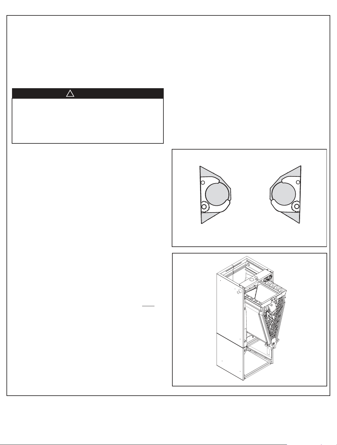
IMPORTANT: The two lamp brackets are not symmetrical. One is
marked Right and the other is marked Left. These markings apply to an
air handler in the vertical upflow configuration (with V-shaped coil orientation). It is very important that the right side and left side brackets are
placed on the proper side so that UV light is directed toward the center
of the coil. Further references to left and right side brackets, top, and bottom in this document assume upflow air handler configuration. For other
configurations see the illustration on page 4 for proper bracket location.
NOTE: Use isopropyl alcohol to thoroughly clean and dry the surfaces
of the inside coil compartment wall in the areas where the lamp brackets
and ballast assembly will be permanently mounted.
NOTE: For new air handler installations, if a UV lamp kit is installed, it
is recommended to remove the coil and install the lamp brackets before
installing the air handler.
Left
End views
(Front of unit)
Right
18-GJ11D1-2
3
Page 4
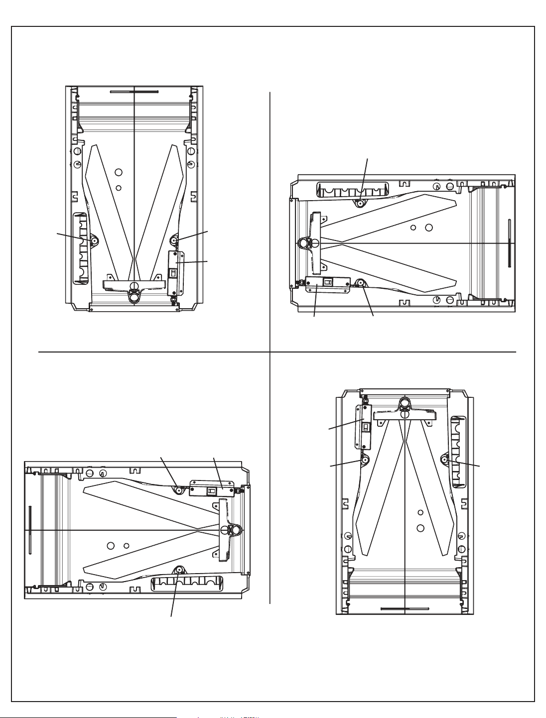
Right Bkt
Upflow
Horizontal Right
Downflow
Horizontal Left
Left Bkt
Ballast
Right Bkt
Left Bkt
Ballast
Right Bkt
Left Bkt
Ballast
Right Bkt
Left Bkt
Ballast
UV Lamp Brackets and Ballast locations for Air Handler Orientations
4
18-GJ11D1-2
Page 5

Right Side UV Lamp bracket installation
3.
Scribe Horizontal Line
Locating Bottom of Lamp
Brac
ket
Lamp Brac
ket - Right Side
the right of the templat
e
.
7.5”
STEP 1. Remove coil panel. See the air handler Installer’s Guide
for additional information if needed.
STEP 2. Cut the cable tie from the right side lamp bracket as-
sembly. Slide the lamp and reflector assembly out of the
bracket as shown.
STEP 3. Measure 7.5 inches above the cross bar and make
a mark on the inside of the air handler cabinet (use a
screwdriver or other metal object to scribe line).
STEP 4. Draw a level line to the back of the air handler
cabinet. This line will be used as a guide for the proper
placement of the lamp bracket. The bottom of the lamp
bracket will line up with the scribe line.
End View
18-GJ11D1-2
Cross Bar
5
Page 6
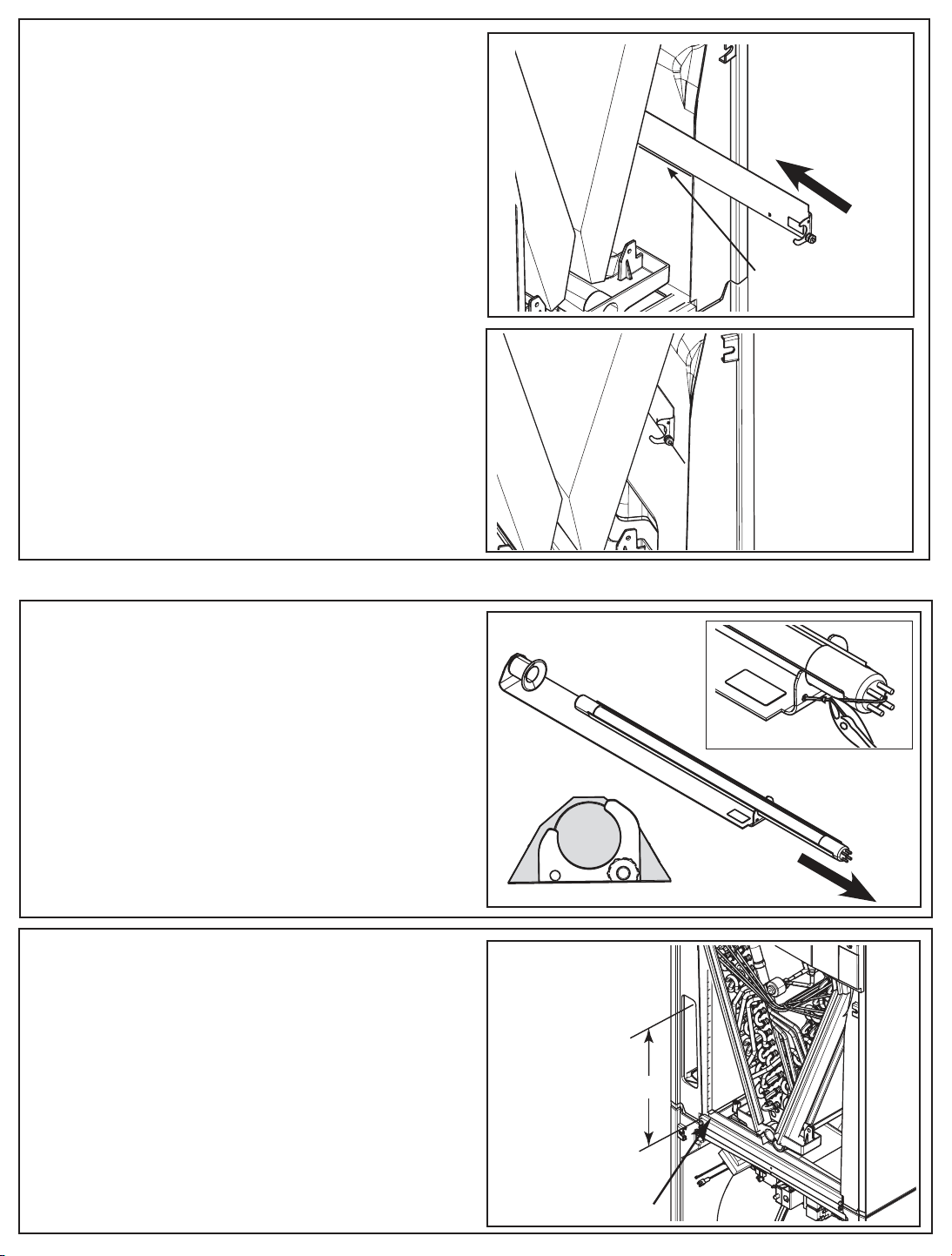
STEP 5. Once a proper dry fit has been verified, use the alcohol
7.5”
3
.
Scribe Horizontal Line
Locating Bottom of Lamp
Brac
ket
-
swabs to clean the area where the bracket is to be mounted.
STEP 6. Remove liner from adhesive on back of bracket and care-
fully place bracket in coil compartment.
STEP 7. Apply pressure firmly over all areas of the bracket to
permanently secure the adhesive to the coil compartment
inner wall.
Scribe Line
Left Side UV Lamp bracket installation
STEP 8. Cut the cable tie on the left side lamp bracket assembly.
Slide the lamp and reflector assembly out of the lamp bracket
as shown.
STEP 9. Measure 7.5 inches above the cross bar and make a
mark on the inside of the air handler cabinet. Follow the same
process as the right side bracket.
Perform a dry fit test before cleaning the air handler cabinet and
securing the bracket in place.
End View
Cross bar
6
18-GJ11D1-2
Page 7
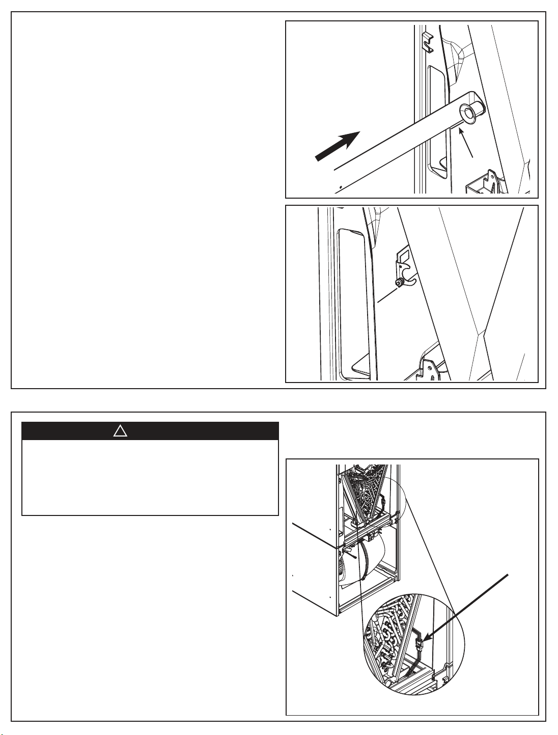
Ballast assembly installation
▲
WARNING
!
HAZARDOUS VOLTAGE! Multiple power sources may
be present. Disconnect all electrical power, including remote
disconnects, before servicing. Follow proper lockout/tagout
procedures to ensure the power can not be inadvertently
energized. Failure to disconnect power before servicing could
result in death or serious injury.
Scribe Line
IMPORTANT: For easy of installation, the Power Plugs must be con-
nected before installing the ballast as
IMPORTANT: The ballast assembly is provided with aggressive adhesive on back. The adhesive has a peel-off liner. Do not remove the liner
until proper mounting locations within the unit have been confirmed.
NOTE: Use isopropyl alcohol to thoroughly clean and dry the surfaces
of the inside coil compartment wall in the areas where the ballast assembly will be permanently mounted.
STEP 10. Disconnect the high voltage wiring harness on the right
side of the indoor coil.
18-GJ11D1-2
sembly in the unit.
7
Page 8
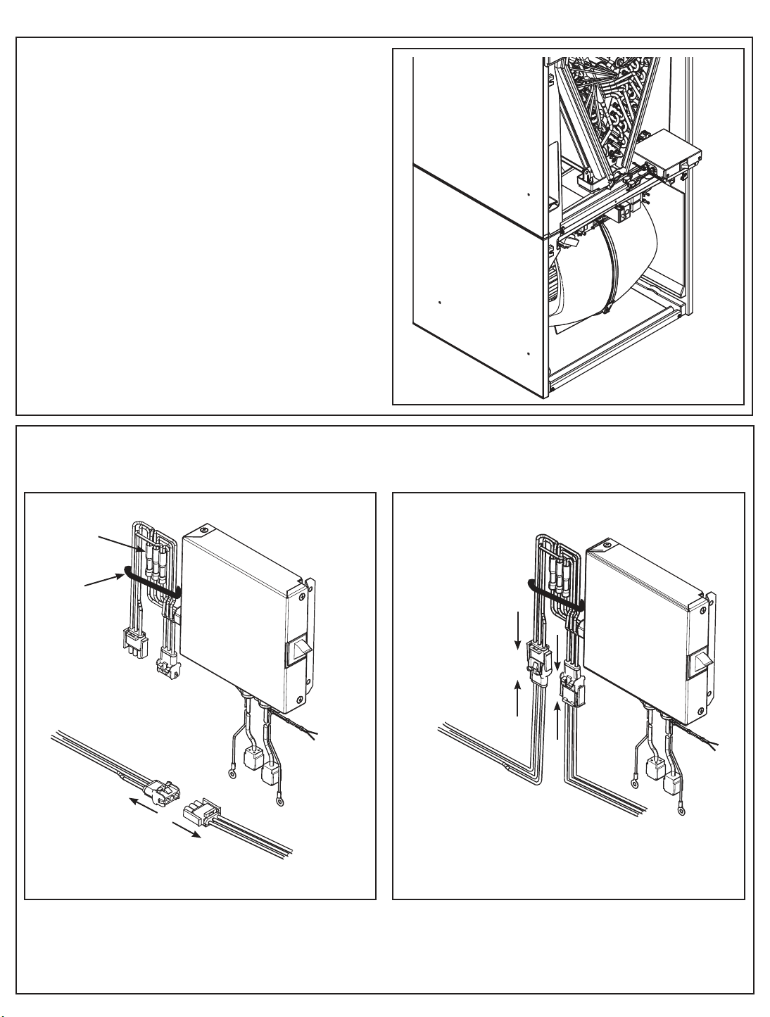
Installing power wiring connections
STEP 11. Rest the ballast assembly on top of the cross brace.
IMPORTANT: Do not cut or remove the cable tie that holds the
ballast assembly power plugs. The tie prevents strain on the
splices.
STEP 12. Connect the ballast assembly in series with the high voltage
leads.
Ballast assembly
Splices
Do not cut
or remove
Ballast power
plugs
From Coil
Compartment
Disconnect air handler power
junction plugs
with power plugs
- Unconnected
From Blower
Compartment
Ballast assembly
with power plugs
- Connected
From Coil
Compartment
From Blower
Compartment
8
18-GJ11D1-2
Page 9
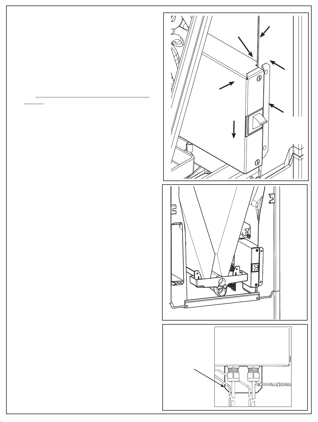
IMPORTANT: The ballast and bracket assembly is provided
with aggressive adhesive on back with peel-off liner. Before
removing adhesive liner, temporarily place ballast and bracket
assembly into unit to determine proper mounting location.
IMPORTANT: For 17.5” wide cabinets, Do Not remove the
adhesive liner. The ballast will be held on by screws only
allowing for easy removal to access to the blower plug if
needed.
Notch
Air handler
ridge
1
STEP 13. Test fit by carefully placing the ballast and bracket assembly
in the unit.
The ballast should be level and resting on the air handler cross bar.
The notch of the ballast assembly will slide into the ridge of the
air handler. Ensure a solid fit before removing peel-off liner and
exposing the adhesive back.
Note: Be careful not to trap or pinch wires behind or below the
ballast assembly.
STEP 14. Once a proper dry fit has been verified, use the isopropyl alco-
hol swabs to clean the area where the ballast is to be mounted.
1. Remove the adhesive liner and follow the previous steps. Do not
let the adhesive backing touch the cabinet until the ballast is in
place.
2. Once the ballast assembly is in place, apply firm pressure to secure
to the inner wall of the air handler.
3
2
Ballast
assembly
front
flange
18-GJ11D1-2
Ballast assembly
bracket that rests upon
the cross bar.
9
Page 10
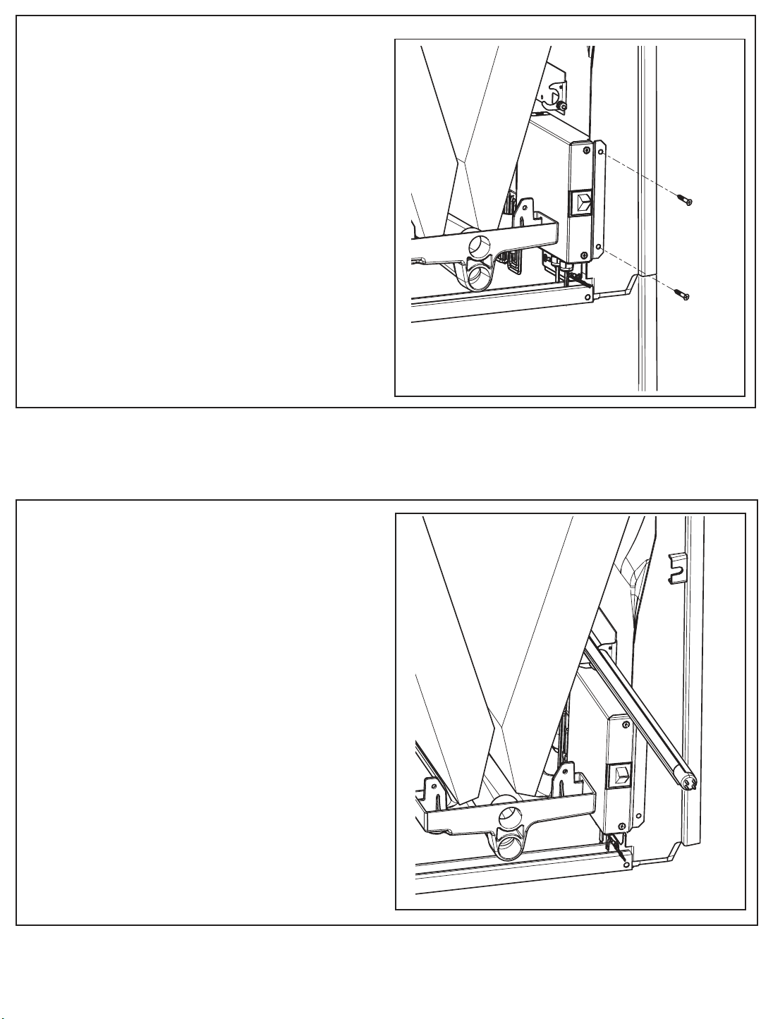
STEP 15. Attach the two supplied screws through the holes in the
bracket. Use a low torque setting when drilling in screws.
IMPORTANT: Use the provided cable ties to secure the wires
behind the cross bar.
Installing UV Lamp wiring connections
NOTE: If the coil was removed before installation, replace the coil
before continuing with the kit installation.
STEP 16. Install the left and right side lamps and reflectors into
their brackets.
IMPORTANT: The lamp is held in place by a metal reflector that
is slightly elliptical. You may need to rotate the lamp when sliding
it into the bracket. The lamp will slide in easily once properly
aligned.
10
18-GJ11D1-2
Page 11
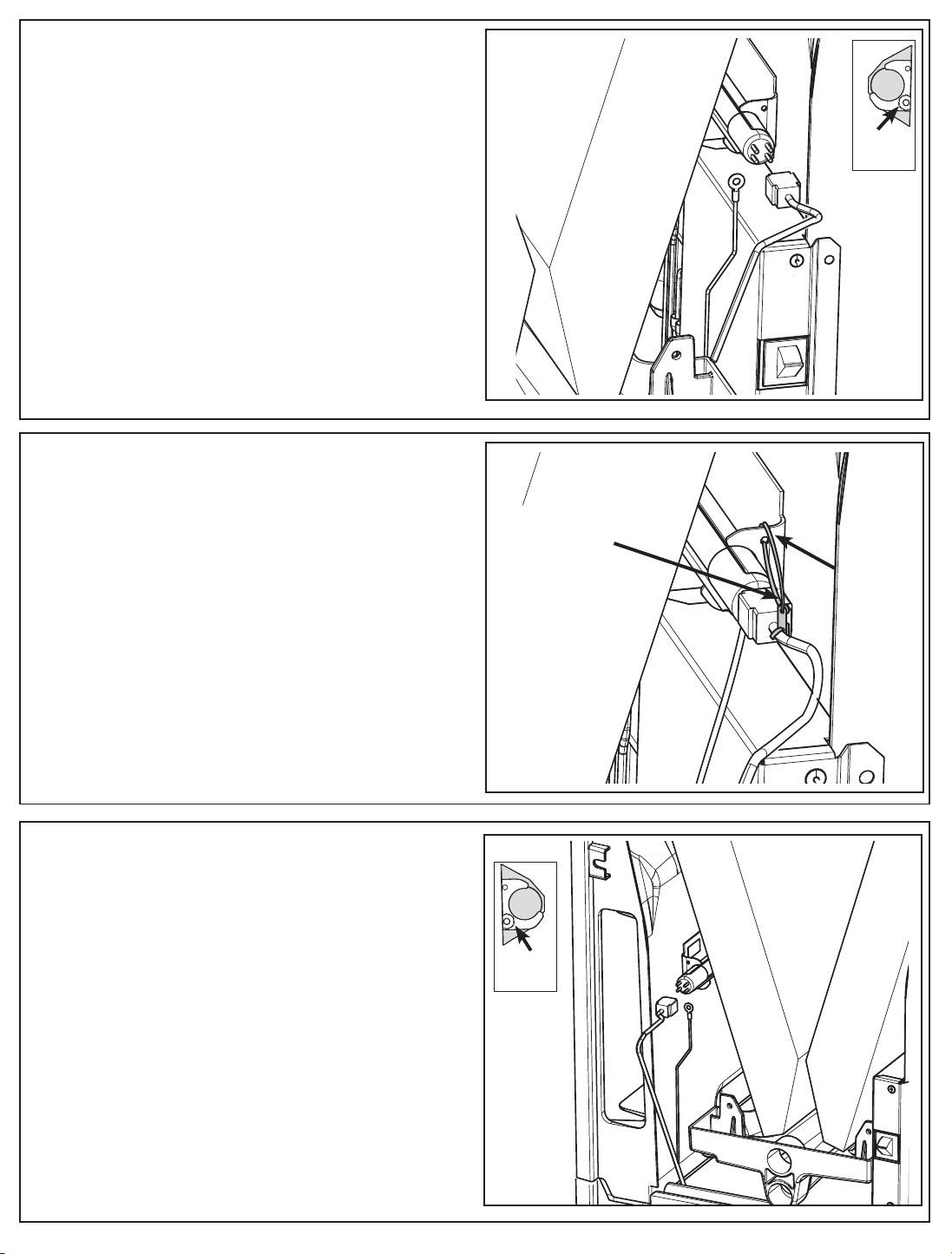
Note: There are two connecting harnesses for the lamps. The short
harness is for the right lamp. The longer harness is for the left
lamp.
STEP 17. Route the right hand lamp connector and ground wire har-
ness to the right hand lamp.
STEP 18. Place the ground wire on the stud. Place a factory supplied
nut on the ground stud and tighten it to secure the grounding wire
in place. Then place a second factory supplied nut onto the stud
and tighten in place also.
STEP 19. Support the lamp and place the pin connector on the lamp.
The connector is position sensitive and will slide on easily when
in the proper orientation.
STEP 20. Use one of the provided cable ties to secure the lamp to the
bracket. Loop the cable tie around the lamp bracket and through
the eyelet on the plug.
Ground
Nuts
Through eyelet
Cable tie
through
hole in
bracket
STEP 21. Follow the same process for the second lamp.
18-GJ11D1-2
Ground
Nuts
11
Page 12
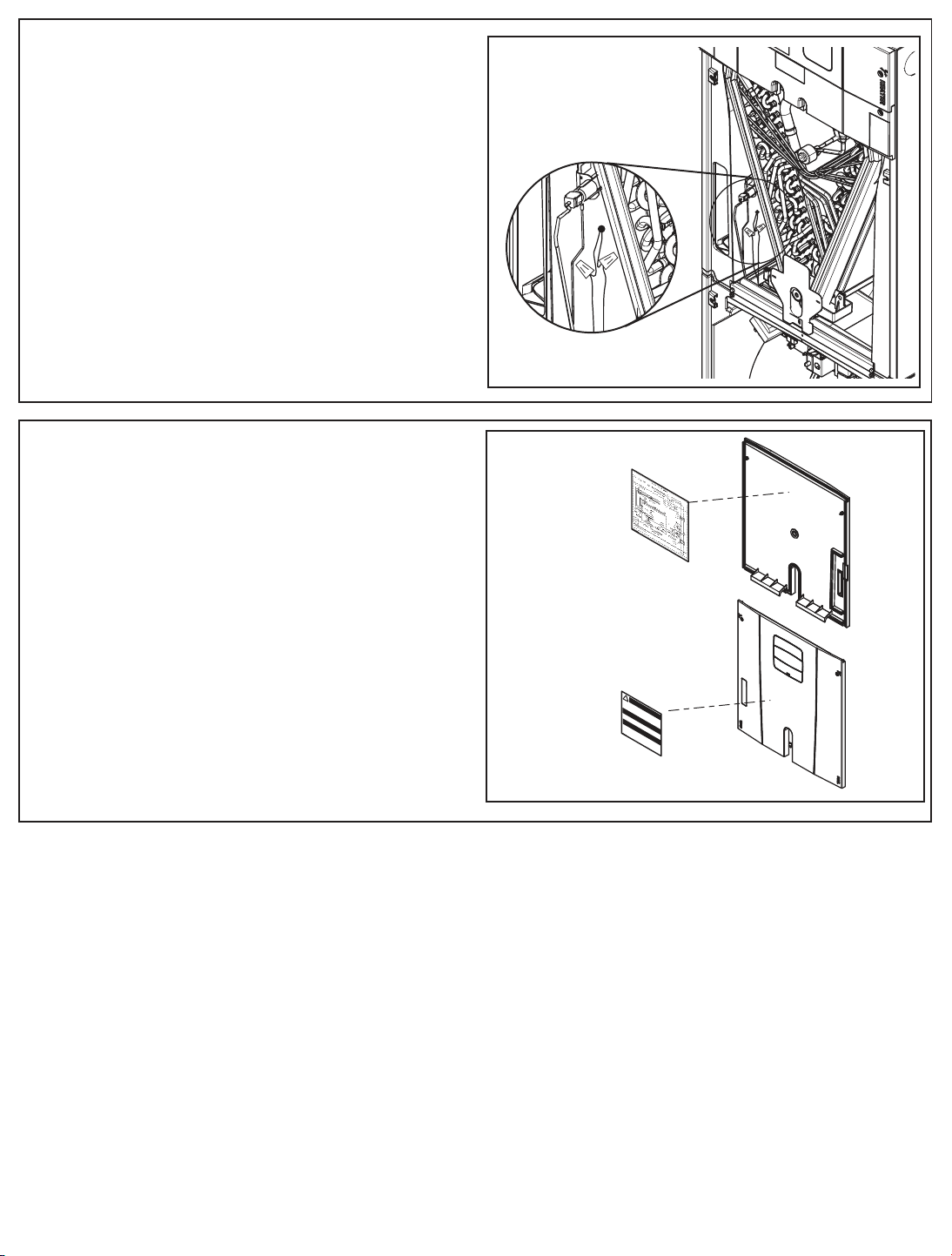
STEP 22. There are two yellow control wires in the UV accessory
3
.
Scribe Horizontal Line
Locating Bottom of Lamp
Brac
ket
-
Br
-
that are only used with Series 8 air handlers. Connect these two
wires to the two yellow UV Light wires in Series 8 air handlers
as shown using the wire nuts provided. (Refer to air handler
wiring diagram .)
For all other air handlers stow these wires securely and leave them
unconnected.
NOTE: A BAYCC24VK01 can be installed for Series 8 Air Handlers to extend the life of the lamp. This accessory kit will disable
the lamp during the heating season (kit is purchased separately).
STEP 23. Use the provided cable ties to secure all wires
STEP 24. Apply wiring diagram label to the inside of the coil com-
partment panel.
IMPORTANT: Make sure all wires are secured completely behind
the crossbar and below the coil to prevent wire damage when coil
panel is replaced.
STEP 25. Apply UV Hazard warning label to the outside of the coil
compartment panel. Place panels back on air handler.
Series 8 Air Handler Only
12
18-GJ11D1-2
Page 13
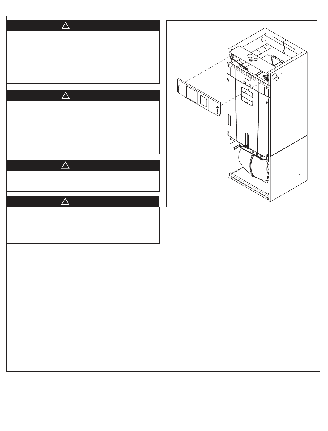
Testing for Proper Operation
▲
WARNING
!
▲
WARNING
!
▲
WARNING
!
▲
WARNING
!
SAFETY HAZARD! This information is for use by individu-
als having adequate backgrounds of electrical and mechanical
experience. Any attempt to repair a central air conditioning
product may result in personal injury and/or property damage. The manufacturer or seller cannot be responsible for the
interpretation of this information, nor can it assume any liability
in connection with its use.
PERSONAL INJURY HAZARD! Disconnect input
power before beginning installation. Professional installation
required per NEC standards. The power supply to this ultraviolet appliance must be disconnected before opening or servicing
the unit. Any access panels or doors, within sight of the UV
lamps, must be interlocked so as to disconnect power to the
UV appliance upon opening or removal.
PERSONAL INJURY HAZARD! UV-C can be harmful
to unprotected eyes. Do not troubleshoot the lamps by sight.
ELECTRICAL HAZARD! The ballast produces a very
high voltage. Checking for voltage output is likely to cause
damage to the meter. Failure to follow this warning could result
in property damage, serious personal injury, or death.
STEP 26. Remove the heater panel.
STEP 27. Set the system comfort control to OFF and restore
power.
STEP 28. Use an ammeter to check for current flow on the high volt-
age wires entering the air handler. The lamps should generate
approximately 0.2 amps of current when energized.
The Series 8 air handler with a BAYCC24VK01 kit will energize the
lamps when the system is in the cooling mode. The lamps will
remain energized for 48 hours after then end of cooling mode.
This minimizes the short cycling of the lamps.
Step 29. Replace the heater panel and restore the system comfort
control to its original setting.
18-GJ11D1-2
13
Page 14
▲
WARNING
!
▲
CAUTION
!
Maintenance
IMPORTANT: A UV lamp’s characteristic blue glow remains long after
its output drops below an effective level and is not a reliable indicator
of the need for replacement. Contact your dealer to order and install
replacement lamps. To maintain peak efficiency, replace bulb every two
years of operation.
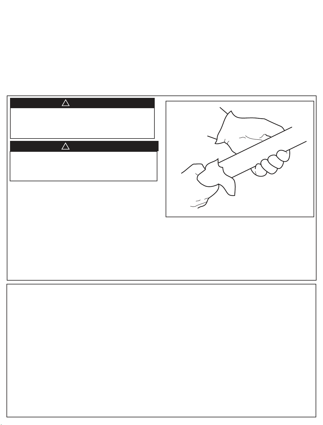
IMPORTANT: Use a clean dry cloth (not bare hands) or clean the lamp
with alcohol or window cleaner after handling.
IMPORTANT: Contact your Dealer for cleaning and maintenance.
HAZARDOUS VAPORS! If UV bulbs are broken, an
appropriate respirator should be considered to prevent inhalation of mercury vapors. Failure to use a respirator could
result in death or serious injury
BROKEN GLASS! Bulbs are fragile and can be easily
broken. Always use gloves and eye protection when handling
these bulbs. Failure to handle bulbs properly may result in
minor to moderate injury.
IMPORTANT: The lamp must remain clean for optimal performance.
IMPORTANT: UV lamps contain mercury, which is a regulated hazard-
ous waste. Disposal of these lamps is subject to state and federal regulations. Although regulations vary from state to state, disposal requirements for UV lamps typically conform to those for fluorescent bulbs. The
Association of Lighting and Mercury Recyclers (ALMR) is a nonprofit,
educational, and informative source on mercury recycling and disposal.
To learn about individual state recycling programs, visit their web site at
http://www.almr.org/index.htm.
UV Lamp Replacement
1. Disconnect all electrical power to the unit.
2. Open the coil panel.
3. Cut the cable tie and remove the plug from the lamp.
4. Wearing soft cloth gloves and safety glasses, use two
hands and firmly grasp the lamp at nearest end.
5. Slide the lamp and reflector shield out of the unit.
6. Remove the reflector from lamp.
7. Snap the reflector on the new lamp.
8. Install the new lamp.
9. Place the plug on the lamp.
10. Replace the coil panel.
Cleaning the UV Lamps
1. Disconnect all electrical power to the unit.
2. Open the coil panel.
3. Cut the cable tie and remove the plug from the lamp.
4. Wearing soft cloth gloves and safety glasses, use two hands
and firmly grasp the lamp at nearest end.
5. Remove the lamp and reflector from the lamp bracket and
slide the lamp out of the unit.
6. Remove the reflector from the lamp.
7. Wipe the lamp with a clean cloth and rubbing alcohol or
glass cleaner. Avoid touching the lamp with bare hands as skin
oils can accelerate future glass soiling and degrade the lamp
performance.
8. Replace the reflector on the lamp.
9. Reinstall the lamp.
10. Replace the plug on the lamp.
11. Replace the coil panel.
IMPORTANT: The lamp is held in place by a metal reflector
that is slightly elliptical. You may need to rotate the lamp
when sliding it into the bracket. The lamp will slide in easily
once properly aligned.
IMPORTANT: The lamp is held in place by a metal reflector
that is slightly elliptical. You may need to rotate the lamp
when sliding it into the bracket. The lamp will slide in easily
once properly aligned.
14
18-GJ11D1-2
Page 15
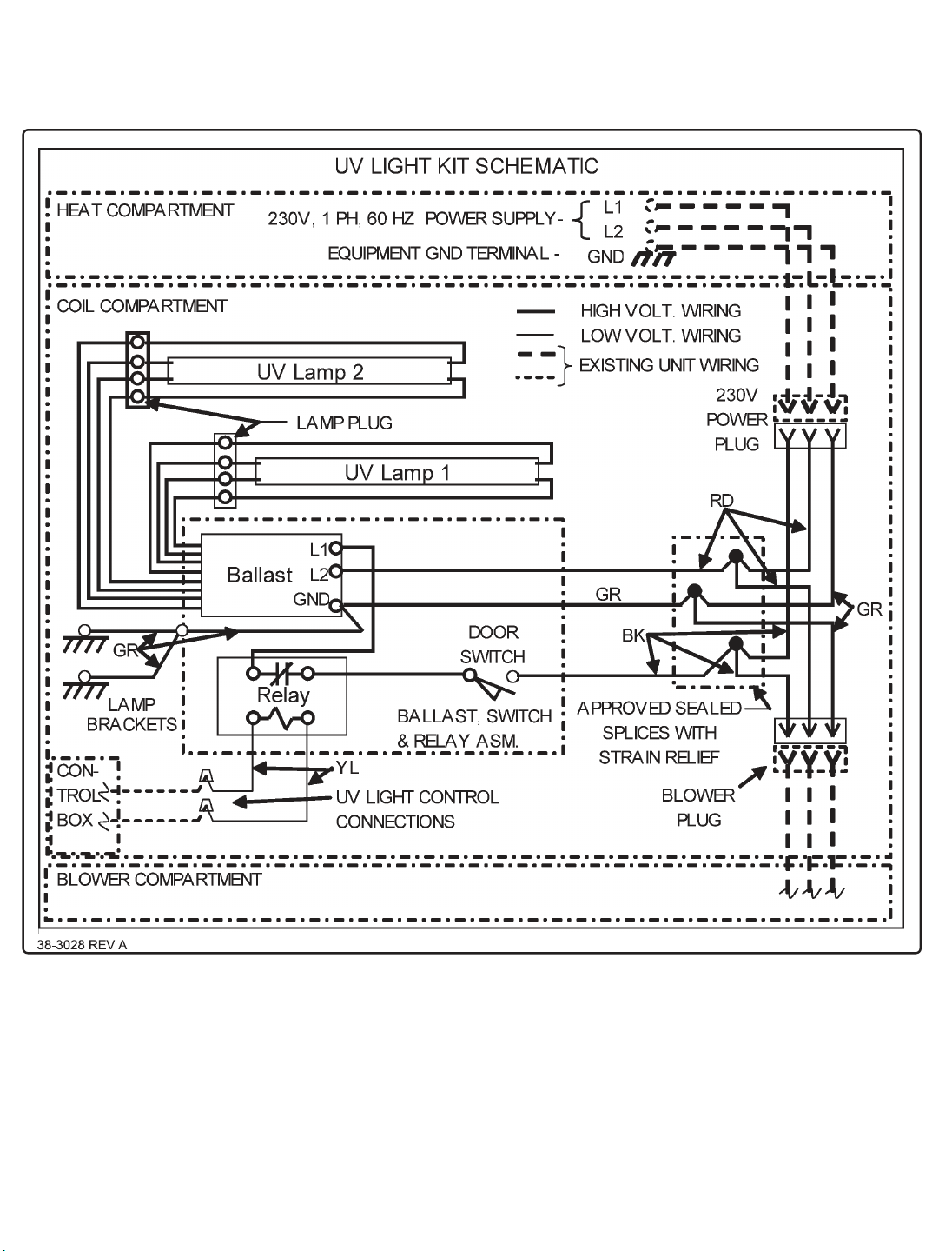
Wiring Diagram
18-GJ11D1-2
15
Page 16

Trane
6200 Troup Highway
Tyler, TX 75707
12/10
Since the manufacturer has a policy of continuous product and product data
improvement, it reserves the right to change design and specifications without notice.
 Loading...