

Trane BAYEVAC08LG1A, BAYEVAC08BK1A, BAYEVAC10LG1A, BAYEVBC15BK1A, BAYEVAC05LG1A Installer's Manual
...
18-GJ09D1-5
▲
WARNING
!
▲
WARNING
!
▲
CAUTION
!
▲
WARNING
!
INSTALLER'S
GUIDE
ALL phases of this installation must comply with
NATIONAL, STATE AND LOCAL CODES
Models:
BAYEVAC05BK1A
BAYEVAC05LG1A
BAYEVAC08BK1A
BAYEVAC08LG1A
BAYEVAC10BK1A
IMPORTANT — This Document is customer property and is to remain with this unit. Please return to ser vice information
pack upon completion of work.
BAYEVAC10LG1A
BAYEVBC15BK1A
BAYEVBC20BK1A
BAYEVAC10LG3A
BAYEVBC15LG3A
Supplementary
Electric Heaters
for Air Handler Installations
Section 1. Safety Information
SAFETY HAZARD! This information is intended for use
by individuals possessing adequate backgrounds of electrical
and mechanical experience. Any attempt to repair a central air
conditioning product may result in personal injury and/or property
damage. The manufacturer or seller cannot be responsible for the
interpretation of this information, nor can it assume any liability in
connection with its use.
HAZARDOUS VOLTAGE! Disconnect all electric
power, including remote disconnects before servicing. Follow
proper lockout/tagout procedures to ensure the power can not
be inadvertently energized. Failure to disconnect power before
servicing could result in death or serious injury.
LIVE ELECTRICAL COMPONENTS! During in-
stallation, testing, servicing, and troubleshooting of this product,
it may be necessary to work with live electrical components.
Failure to follow all electrical safety precautions when exposed to
live electrical components could result in death or serious injury.
SAFETY HAZARD! Sharp Edge Hazard. Be careful of
sharp edges on equipment or any cuts made on sheet metal while
Table of Contents
Section 1. Safety Information .......................................................................................................1
Section 2. General Information .....................................................................................................2
Section 3. Heater Assembly Labeled ...........................................................................................2
Section 4. Heater Selection...........................................................................................................3
Section 5. Adjust Heater ...............................................................................................................5
Section 6. Install Heater ................................................................................................................7
Section 7. Tables ..........................................................................................................................12
Section 8. Sequence of Operation .............................................................................................14
installing or servicing. Personal injury may result.
© 2012 Trane
10/12
INSTALLER'S GUIDE
Section 2. General Information
This electric heater accessory is designed to provide
power directly to the air handler from the accessory
heater's power supply, eliminating the need for additional circuits. The power and control wiring each use
a single wire harness to connect the heater and the air
handler.
1. Check the heater nameplate to confirm that the selected
heater is approved for use with the air handler.
2. Check the components received for damage. Report any
defects or shortages to the transportation company immediately.
3. Be sure the power supply matches the listing shown on
the heater nameplate.
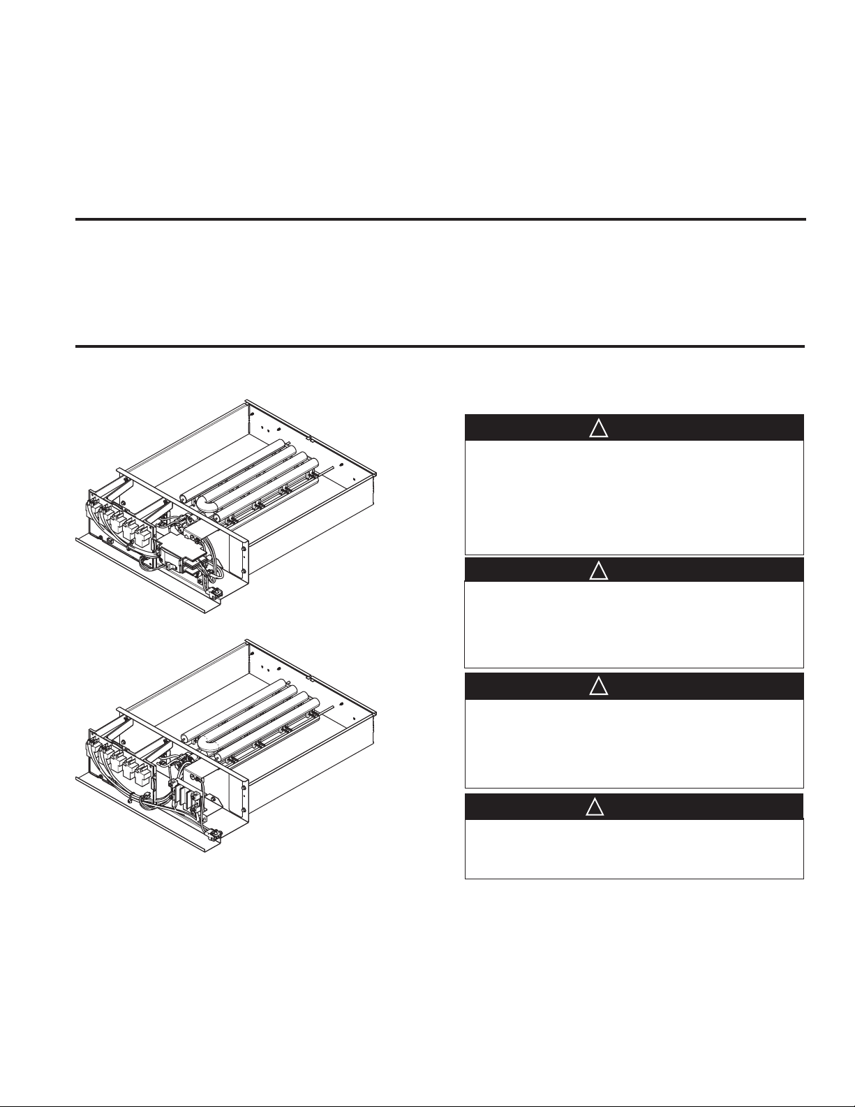
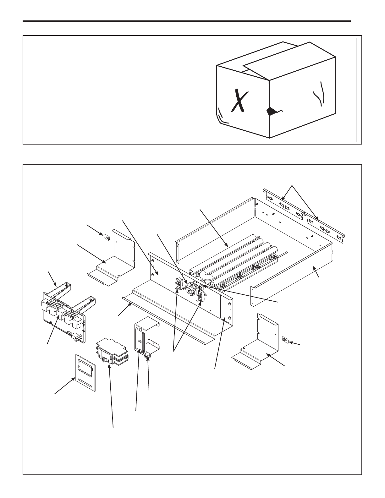
Section 3. Heater Assembly Labeled
Width Adjustment Brackets
Retainer Tab and
Screw
- In document pack
Filler Plate
Electric Heat
Control Platform
Electric Heat
Control Communicating
Base Plate
Edge Guard
- In document
pack
Heater Rack
Cyclic Thermal
Limit Switch
Heater Element
Terminations
Nameplate
Heater Baffle
Non-Cyclic Thermal
Limit Switch
Retainer Tab and
Screw
- In document pack
Filler Plate
Seal Plate
(Breaker models only)
- In document pack
Page 2
Ground Lug
(LG heater has terminal lug)
Breaker Bracket
(LG heater terminal bracket differs)
Circuit Breaker
(Breaker models only)
Wiring diagram not shown
8/10 kW breaker model illustrated
INSTALLER'S GUIDE
Section 4. Heater Selection
Determine which heater best fits your application needs. In addition to electrical considerations, you must know your
cabinet size and the range of heaters which fit that cabinet.
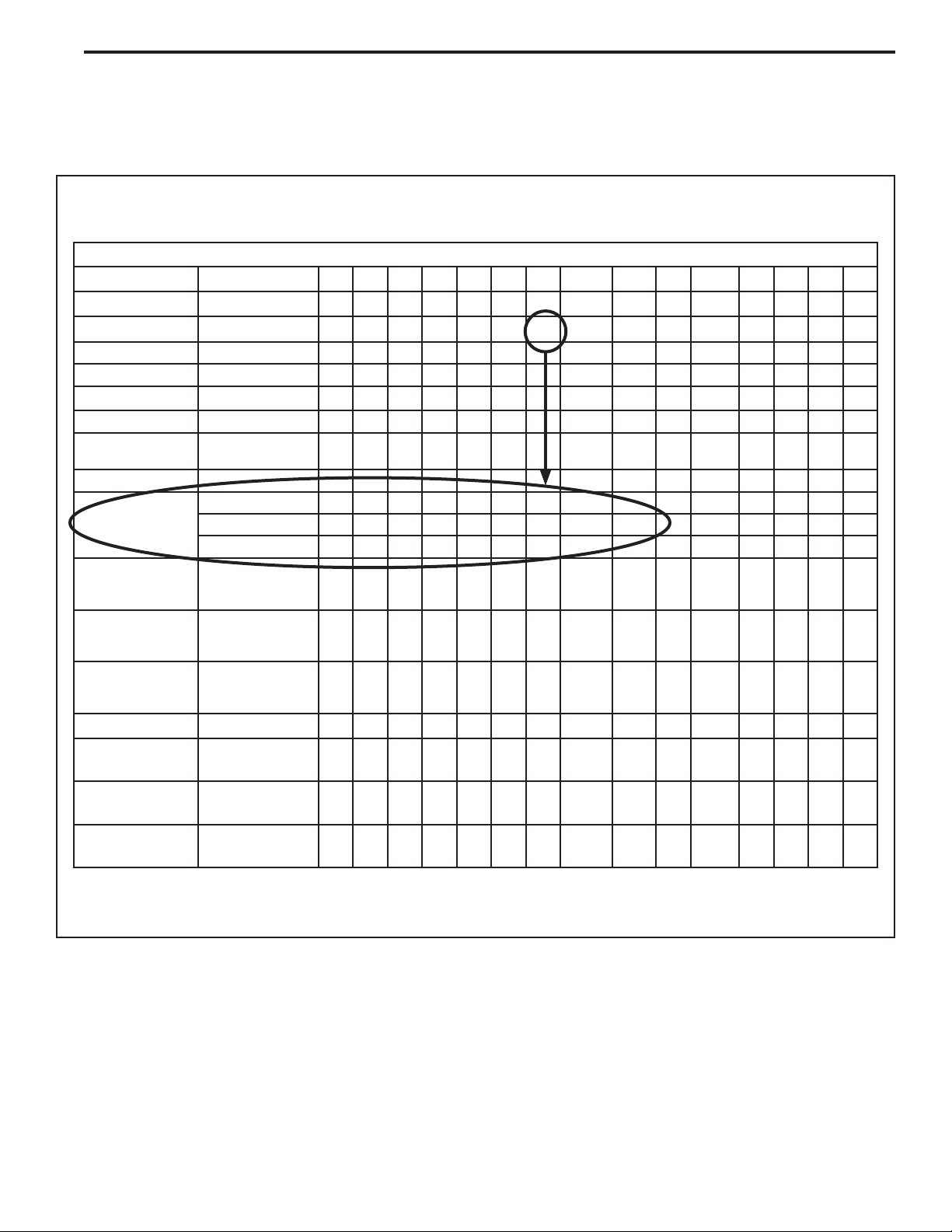
4.1 Air Handler Model Number Matrix
Step 1 - Measure your cabinet and use the Air Handler
Model Number Matrix to determine your cabinet size.
Air Handler Model Number Matrix
Digit 1 2 3 4 5 6 7 8 9 10 11 12 13 14 15
Example
Brand
Product Type Air Handler
Convertibility Multi-poise 4-way
Product Tier Multi-speed
Major Design
Modifications
No Descriptor Air Handler / Coil
Size (Footprint)
Cooling Size:
Air Handler
Electric Heat Input
Airflow Type &
Capability
Power Supply 208-230/1/60
System Control
Type
Letter
Sequence
17.5 x 21.5
21.0 x 21.5
23.5 x 21.5
AH Coil - 1,000
BTU's (18, 24, 30,
36, 42, 48, 60)
Electric Heat - kW
(05, 08, 10, 15,
20, 25)
H - Hi Effy, Multi-
speed, 1-5 - nom.
Tonnage (cfm/ton)
Standard
- 24 VAC
T A M 7 A 0 B 3 0 H 2 1 S A A
T
A
M
7
A
0
A
B
C
0-9 0-9
0-9 0-9
H 1-5
1
S
Minor Design
Modifications
Unit Parts
Identifier
Letter
Sequence
Letter
Sequence
The cabinet size in this example is B.
Record Your Cabinet Size = _________
A
A
This matrix is provided as an example only.
Page 3

INSTALLER'S GUIDE
Step 2 - Use the Heater Model Number Matrix to determine which heaters will fit in your cabinet and to
determine if you will have to modify the heater to fit the
cabinet.
Electric Heat Model Number
Digit 1 2 3 4 5 6 7 8 9 10 11 12 13 14 15
Example
Brand Both Brands B
Product Type Accessory A Y
Heat Type Electric Heater E
Product Tier Air Handler Tier
Size
(Footprint)
Electric Heat Input Electric Heat - kW (05,
Connection Breaker B K
Power Supply 208-230/1/60 1
(7 and 8)
Minimum Cabinet
Width (A,B,C)
Maximum Cabinet
Width (A,B,C)
08, 10, 15, 20, 25)
Lugs L G
B A Y E V A C 1 5 B K 1 A A A
V
A
C
0-9 0-9
200/1/50 A
208-230/3/60 3
Major Design Modifications Letter Sequence A
Minor Design Modifications Letter Sequence A
Unit Parts Identifier Letter Sequence A
The heater in this example will fit into cabinets A, B, & C.
From Step 1 we know that the heater needs to be sized
to fit in a B cabinet.
See Section 5 for instructions for modifying your heater
to fit various cabinet sizes.
Record Your Heater Size = _________
This matrix is provided as an example only.
Page 4
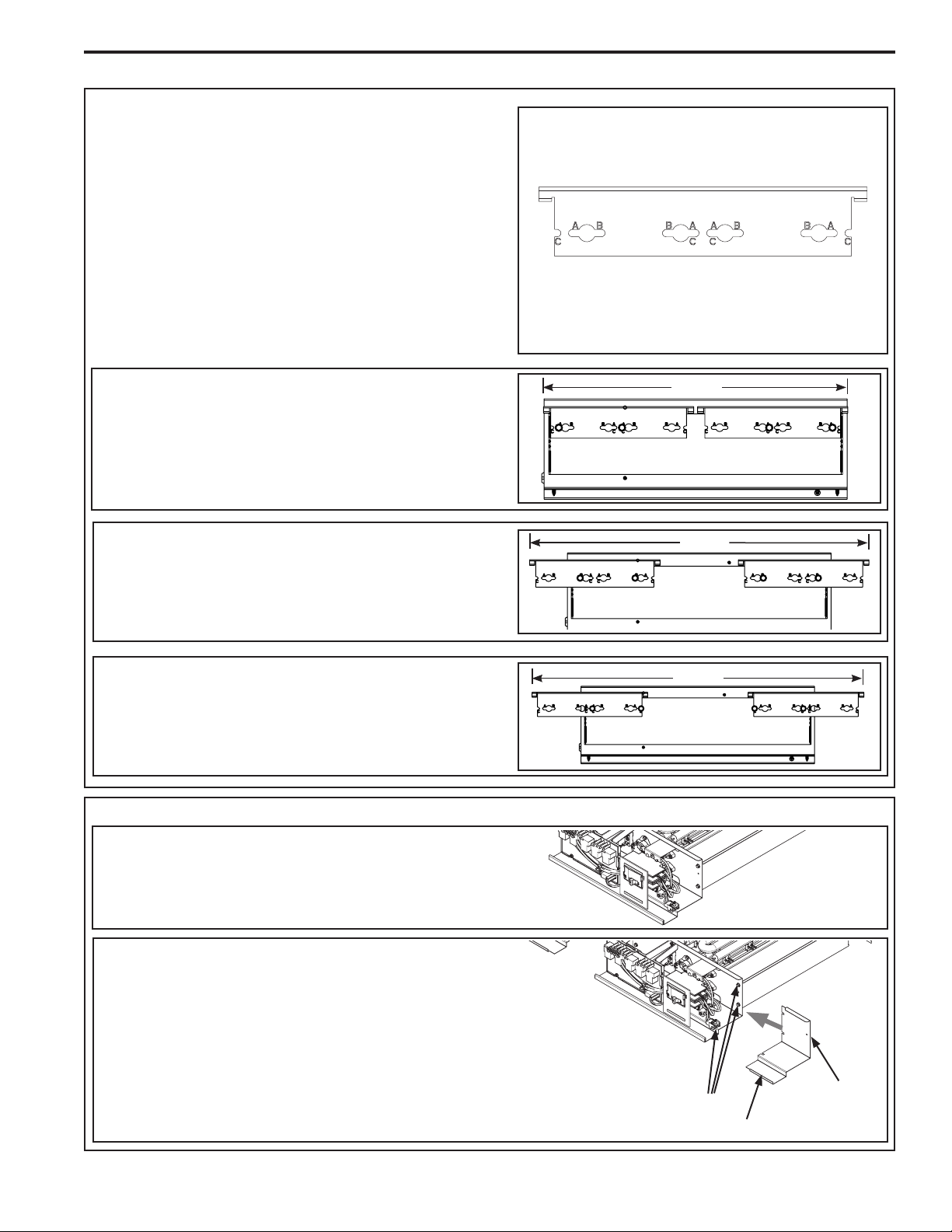
Section 5. Adjust Heater
STEP 1 - Position Width Adjustment Brackets.
Two Width Adjustment Brackets are located at the
back of the heater assembly. The heater comes
sized for the smallest cabinet it will fit in. For this
example our heater fits cabinets A, B, and C. It came
sized for an A cabinet and we are sizing it for a B
cabinet.
1. Loosen the screws that hold the Width Adjustment
Brackets to the back of the heater.
2. Reposition each Width Adjustment Bracket until the
correct holes line up with the loosened screws as illustrated in this step.
3. Tighten screws to hold Width Adjustment Bracket
securely in place.
INSTALLER'S GUIDE
Width Adjustment Brackets
(two per unit)
Cabinet A
The heater comes from the factory sized for cabinet
A. No modifications to the Width Adjustment
Brackets are required.
Cabinet B
Prepare the heater for cabinet B by modifying the
Width Adjustment Brackets to align with the holes
labeled B.
Cabinet C
Prepare the heater for cabinet C by modifying the
Width Adjustment Brackets to align with the holes
labeled C.
STEP 2 - Adjust Filler Plates.
14.5
18.5
20.5
Cabinet A
NOTE: No Filler Plates are required for the A cabinet.
Cabinet B or C
1. Loosen the Filler Plate screws on each side of Base
Plate (four total).
2. Slide in the correct Filler Plate on each side. Filler
Plates are marked for the cabinet size they match
with, for example, the Filler Plate for cabinet B is
marked "B-CAB".
3. Tighten the Filler Plate screws loosened previously
and add a screw (provided) to the bottom of each
plate to hold Filler Plates in place.
Filler Plate Screws
-three per side
Filler Plate
Retainer Tab
& Screw
Page 5
 Loading...