

Trane BAYEVAC08LG1A, BAYEVAC08BK1A, BAYEVAC10LG1A, BAYEVBC15BK1A, BAYEVAC05LG1A Installer's Manual
...Page 1
18-GJ09D1-5
▲
WARNING
!
▲
WARNING
!
▲
CAUTION
!
▲
WARNING
!
INSTALLER'S
GUIDE
ALL phases of this installation must comply with
NATIONAL, STATE AND LOCAL CODES
Models:
BAYEVAC05BK1A
BAYEVAC05LG1A
BAYEVAC08BK1A
BAYEVAC08LG1A
BAYEVAC10BK1A
IMPORTANT — This Document is customer property and is to remain with this unit. Please return to ser vice information
pack upon completion of work.
BAYEVAC10LG1A
BAYEVBC15BK1A
BAYEVBC20BK1A
BAYEVAC10LG3A
BAYEVBC15LG3A
Supplementary
Electric Heaters
for Air Handler Installations
Section 1. Safety Information
SAFETY HAZARD! This information is intended for use
by individuals possessing adequate backgrounds of electrical
and mechanical experience. Any attempt to repair a central air
conditioning product may result in personal injury and/or property
damage. The manufacturer or seller cannot be responsible for the
interpretation of this information, nor can it assume any liability in
connection with its use.
HAZARDOUS VOLTAGE! Disconnect all electric
power, including remote disconnects before servicing. Follow
proper lockout/tagout procedures to ensure the power can not
be inadvertently energized. Failure to disconnect power before
servicing could result in death or serious injury.
LIVE ELECTRICAL COMPONENTS! During in-
stallation, testing, servicing, and troubleshooting of this product,
it may be necessary to work with live electrical components.
Failure to follow all electrical safety precautions when exposed to
live electrical components could result in death or serious injury.
SAFETY HAZARD! Sharp Edge Hazard. Be careful of
sharp edges on equipment or any cuts made on sheet metal while
Table of Contents
Section 1. Safety Information .......................................................................................................1
Section 2. General Information .....................................................................................................2
Section 3. Heater Assembly Labeled ...........................................................................................2
Section 4. Heater Selection...........................................................................................................3
Section 5. Adjust Heater ...............................................................................................................5
Section 6. Install Heater ................................................................................................................7
Section 7. Tables ..........................................................................................................................12
Section 8. Sequence of Operation .............................................................................................14
installing or servicing. Personal injury may result.
© 2012 Trane
10/12
Page 2
INSTALLER'S GUIDE
Section 2. General Information
This electric heater accessory is designed to provide
power directly to the air handler from the accessory
heater's power supply, eliminating the need for additional circuits. The power and control wiring each use
a single wire harness to connect the heater and the air
handler.
1. Check the heater nameplate to confirm that the selected
heater is approved for use with the air handler.
2. Check the components received for damage. Report any
defects or shortages to the transportation company immediately.
3. Be sure the power supply matches the listing shown on
the heater nameplate.
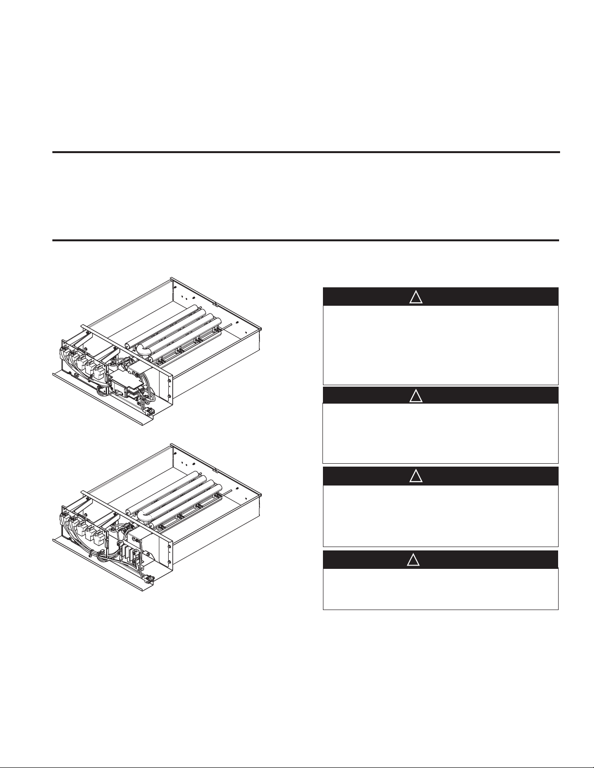
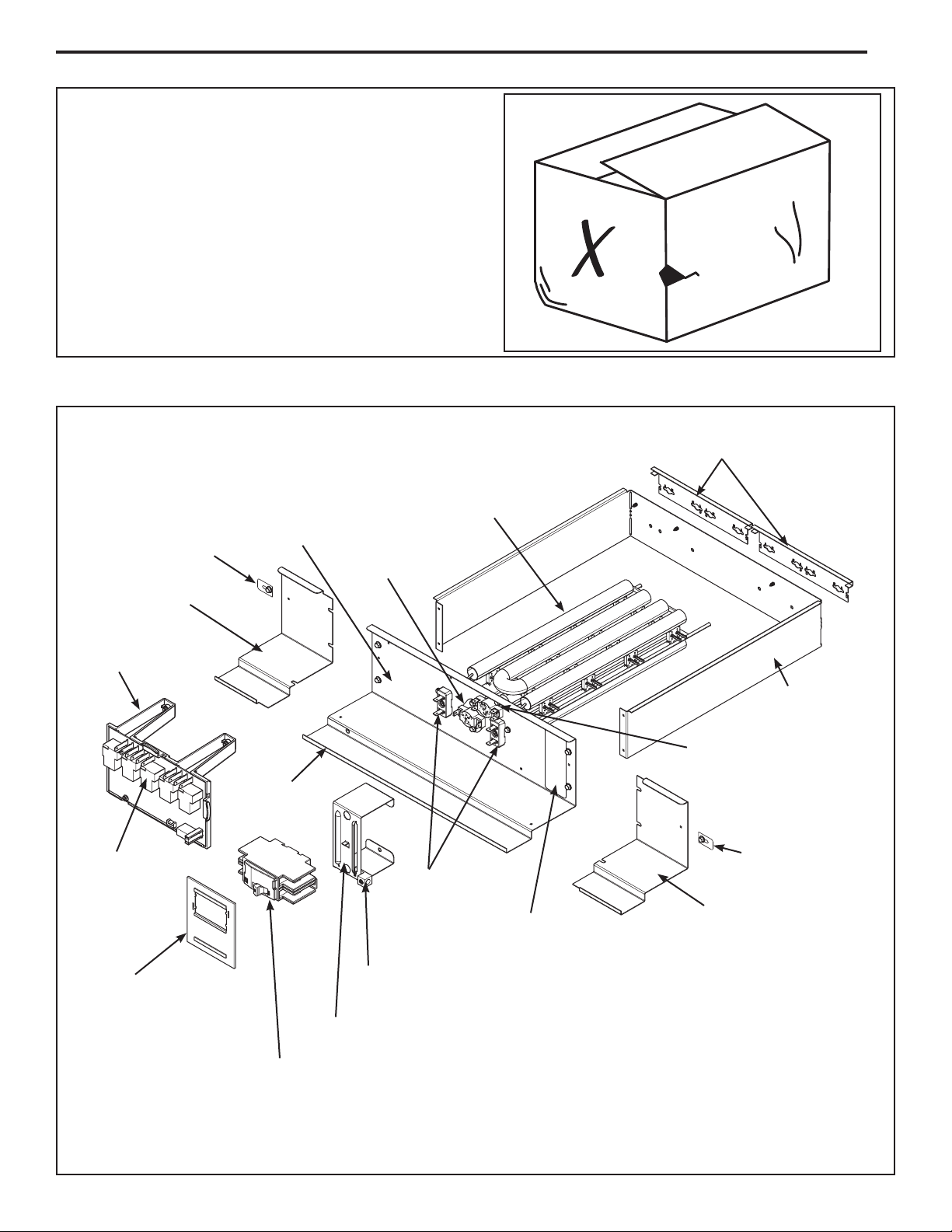
Section 3. Heater Assembly Labeled
Width Adjustment Brackets
Retainer Tab and
Screw
- In document pack
Filler Plate
Electric Heat
Control Platform
Electric Heat
Control Communicating
Base Plate
Edge Guard
- In document
pack
Heater Rack
Cyclic Thermal
Limit Switch
Heater Element
Terminations
Nameplate
Heater Baffle
Non-Cyclic Thermal
Limit Switch
Retainer Tab and
Screw
- In document pack
Filler Plate
Seal Plate
(Breaker models only)
- In document pack
Page 2
Ground Lug
(LG heater has terminal lug)
Breaker Bracket
(LG heater terminal bracket differs)
Circuit Breaker
(Breaker models only)
Wiring diagram not shown
8/10 kW breaker model illustrated
Page 3
INSTALLER'S GUIDE
Section 4. Heater Selection
Determine which heater best fits your application needs. In addition to electrical considerations, you must know your
cabinet size and the range of heaters which fit that cabinet.
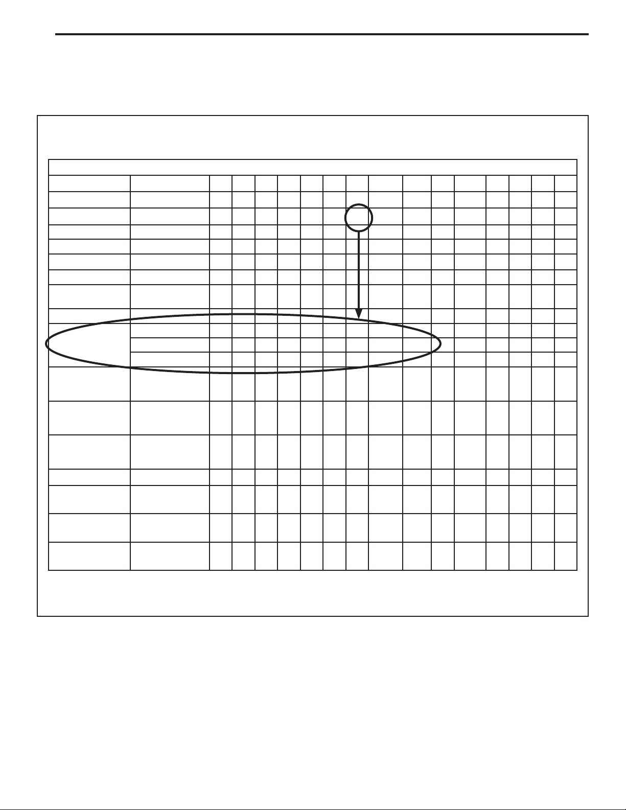
4.1 Air Handler Model Number Matrix
Step 1 - Measure your cabinet and use the Air Handler
Model Number Matrix to determine your cabinet size.
Air Handler Model Number Matrix
Digit 1 2 3 4 5 6 7 8 9 10 11 12 13 14 15
Example
Brand
Product Type Air Handler
Convertibility Multi-poise 4-way
Product Tier Multi-speed
Major Design
Modifications
No Descriptor Air Handler / Coil
Size (Footprint)
Cooling Size:
Air Handler
Electric Heat Input
Airflow Type &
Capability
Power Supply 208-230/1/60
System Control
Type
Letter
Sequence
17.5 x 21.5
21.0 x 21.5
23.5 x 21.5
AH Coil - 1,000
BTU's (18, 24, 30,
36, 42, 48, 60)
Electric Heat - kW
(05, 08, 10, 15,
20, 25)
H - Hi Effy, Multi-
speed, 1-5 - nom.
Tonnage (cfm/ton)
Standard
- 24 VAC
T A M 7 A 0 B 3 0 H 2 1 S A A
T
A
M
7
A
0
A
B
C
0-9 0-9
0-9 0-9
H 1-5
1
S
Minor Design
Modifications
Unit Parts
Identifier
Letter
Sequence
Letter
Sequence
The cabinet size in this example is B.
Record Your Cabinet Size = _________
A
A
This matrix is provided as an example only.
Page 3
Page 4

INSTALLER'S GUIDE
Step 2 - Use the Heater Model Number Matrix to determine which heaters will fit in your cabinet and to
determine if you will have to modify the heater to fit the
cabinet.
Electric Heat Model Number
Digit 1 2 3 4 5 6 7 8 9 10 11 12 13 14 15
Example
Brand Both Brands B
Product Type Accessory A Y
Heat Type Electric Heater E
Product Tier Air Handler Tier
Size
(Footprint)
Electric Heat Input Electric Heat - kW (05,
Connection Breaker B K
Power Supply 208-230/1/60 1
(7 and 8)
Minimum Cabinet
Width (A,B,C)
Maximum Cabinet
Width (A,B,C)
08, 10, 15, 20, 25)
Lugs L G
B A Y E V A C 1 5 B K 1 A A A
V
A
C
0-9 0-9
200/1/50 A
208-230/3/60 3
Major Design Modifications Letter Sequence A
Minor Design Modifications Letter Sequence A
Unit Parts Identifier Letter Sequence A
The heater in this example will fit into cabinets A, B, & C.
From Step 1 we know that the heater needs to be sized
to fit in a B cabinet.
See Section 5 for instructions for modifying your heater
to fit various cabinet sizes.
Record Your Heater Size = _________
This matrix is provided as an example only.
Page 4
Page 5
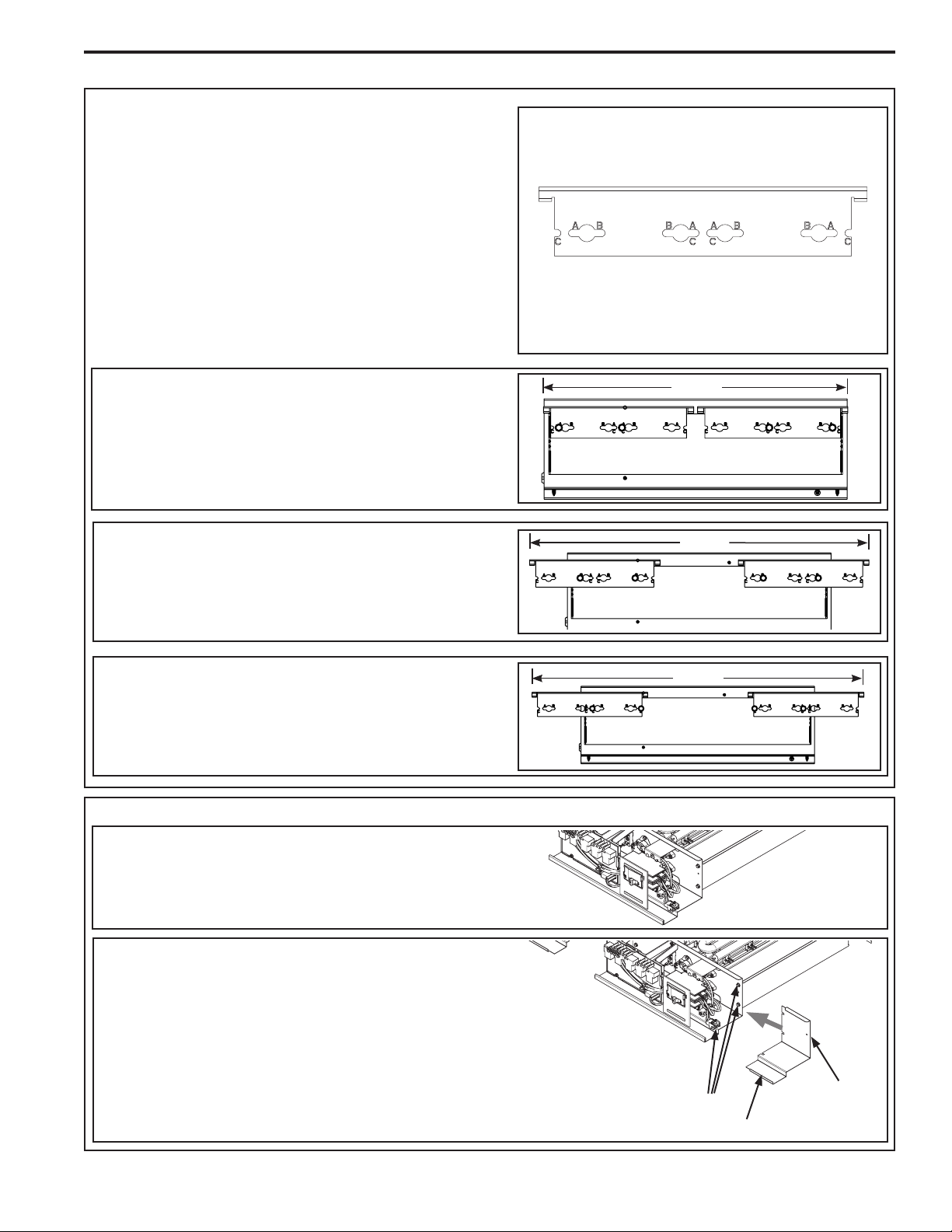
Section 5. Adjust Heater
STEP 1 - Position Width Adjustment Brackets.
Two Width Adjustment Brackets are located at the
back of the heater assembly. The heater comes
sized for the smallest cabinet it will fit in. For this
example our heater fits cabinets A, B, and C. It came
sized for an A cabinet and we are sizing it for a B
cabinet.
1. Loosen the screws that hold the Width Adjustment
Brackets to the back of the heater.
2. Reposition each Width Adjustment Bracket until the
correct holes line up with the loosened screws as illustrated in this step.
3. Tighten screws to hold Width Adjustment Bracket
securely in place.
INSTALLER'S GUIDE
Width Adjustment Brackets
(two per unit)
Cabinet A
The heater comes from the factory sized for cabinet
A. No modifications to the Width Adjustment
Brackets are required.
Cabinet B
Prepare the heater for cabinet B by modifying the
Width Adjustment Brackets to align with the holes
labeled B.
Cabinet C
Prepare the heater for cabinet C by modifying the
Width Adjustment Brackets to align with the holes
labeled C.
STEP 2 - Adjust Filler Plates.
14.5
18.5
20.5
Cabinet A
NOTE: No Filler Plates are required for the A cabinet.
Cabinet B or C
1. Loosen the Filler Plate screws on each side of Base
Plate (four total).
2. Slide in the correct Filler Plate on each side. Filler
Plates are marked for the cabinet size they match
with, for example, the Filler Plate for cabinet B is
marked "B-CAB".
3. Tighten the Filler Plate screws loosened previously
and add a screw (provided) to the bottom of each
plate to hold Filler Plates in place.
Filler Plate Screws
-three per side
Filler Plate
Retainer Tab
& Screw
Page 5
Page 6

INSTALLER'S GUIDE
▲
CAUTION
!
STEP3 - Attach Retainer Tabs and Edge Guard
Note: For A cabinet widths, only the right side
retainer tab must be installed.
1. Add the Retainer tabs using the screws provided (both
tabs and screws are located in the documentation
packet).
Leave the screws slightly loose so that the tab can slide
to the left or right as needed. The tab will be used later
to engage in a slot within the air handler cabinet.
Note: If no filler plates are needed, the retainer tabs
must be attached to the heater coil flange. Leave
the screws slightly loose so they can be slid to the
left or right as needed.
2. The edge guard is located in the document pack. Cut
the edge guard to the length needed for the heater
width, including the filler plates.
3. Install the edge guard on the front of the heater flange
as shown.
STEP 4 - (Optional) Rotate Circuit Breaker Assembly.
Note: For LG (lug) heater models the terminal block
bracket does not rotate.
The need to reorient the Circuit Breaker Assembly
depends upon the orientation of your application
and which of the high voltage electrical conduit entry
points you use for high voltage wiring.
Important: For air handler units installed in the
horizontal right position, the circuit breakers on
the heater must be rotated in order to comply with
National Electric Code (NEC Section 240.81). The
NEC requires that circuit breakers operated vertically must be oriented so that the "on" position of the
breaker is upward.
B and C
Cabinet
Factory
Connections
Circuit
Breaker
Rounded end
inserts into cabinet
A Cabinet
Screw
Field
Connections
ON
SAFETY HAZARD! Sharp Edge Hazard. Be careful of
sharp edges on equipment or any cuts made on sheet metal while
installing or servicing. Personal injury may result.
1. Unscrew the Breaker Bracket from the Base Plate
using a magnetic 1/4" hex driver with an extension.
The extension allows for easier access to the screws
which are located at the back of the bracket.
2. Rotate the bracket with circuit breaker(s) 180 °.
3. Use the screws removed in action 2 (above) to secure
the bracket to the Base Plate.
Page 6
Screw
Circuit Breaker Assembly
Breaker
Bracket
Page 7

Section 6. Install Heater
STEP 1 - Remove Heater Compartment Panel.
STEP 2 - Disconnect & Dispose of Pigtail Harness.
1. Cut the wire tie that is holding the pigtail harness.
2. Unplug and dispose of pigtail harness.
INSTALLER'S GUIDE
Heater
Compartment
Panel
Breaker
Cover
Important: If using a BAYSUPFLGA, B, or C Supply
Duct Flange Kit, install the kit before inserting the
heater.
STEP 3 - Insert heater assembly into heater compartment.
1. Move factory wiring out of the way and into the grooves
provided in cabinet.
2. Slide heater into heater compartment of air handler.
Wire Tie
Pigtail
Harness
Page 7
Page 8

INSTALLER'S GUIDE
STEP - 4 Lock Retainer tabs.
Note: Retainer tabs are used to secure the heater
inside of the heater compartment.
1. Slide retainer tab into recess in air handler cabinet.
2. Tighten screws to hold tab securely.
3. Repeat actions to secure the other tab.
Note: For A cabinet widths, only the right side
retainer tab must be installed.
STEP 5 - Route High Voltage wiring to unit.
Select a conduit entry point. Drill a hole for the desired
conduit size on units without a plug. A locating target is
identified on these units.
Note: Some models may have a pre-molded conduit
connection with plug. If a connection hole is already
present, remove the plug from the entry point and use
as is.
Retainer
Tab
Filler
Plate
(B and C only)
Conduit Entry Points
1. Select the entry point you will use to bring in your
high voltage wiring.
2. Remove plug from the entry point.
STEP 6 - Route conduit, if used, and wiring to the
entry point and connect.
Note: The conduit nut is factory supplied and found in the
air handler document pack.
1. Use one hand to secure the factory supplied conduit nut
from the inside of heater compartment.
2. Connect field supplied 3/4" or 1-1/2" conduit to conduit
nut.
Note: Reducing bushings may be required for your
application.
Page 8
Page 9

INSTALLER'S GUIDE
STEP 8 - Connect high voltage wiring
1. Connect the wiring to the lugs on the breaker models or
to the terminal block on the lug models as illustrated.
2. Connect the ground wire to the ground lug.
3. Connect the 3-pin plug on the heater to the 3-pin plug in
the air handler case.
Note: Minimum terminal screw torque is 45 in-lbs.
Factory
wiring
BLK
RED
Factory
wiring
BLK
RED
Factory
wiring
BLK
Breaker Model
GREEN
Ground
RED
Field wiringFactory wiring
Factory
wiring
Field
wiring
Field
wiring
Field
wiring
Ground
GREEN
3-Phase Model
STEP 9 - Install the seal plate. Breaker models only.
1. Place the seal plate over the breaker so the tab on the
right side is in place.
2. Snap on the left side of the seal plate that has the slot
by the tab.
Field
wiring
Snap in
place over
breaker
second
LG (lug) Model
Field
wiring
Ground
GREEN
Place over
breaker first
Page 9
Page 10

INSTALLER'S GUIDE
STEP 10 - Connect low voltage wiring.
1. Connect the low voltage harness to Electric Heat Control as shown.
Low Voltage
Harness
STEP 11 - Place Wiring Diagram.
1. Attach the wiring diagram, included in the documentation packet, to the back of the heater compartment
panel.
H
WARNING
AZ
A
DIS
RD
CO
OU
INCLUDING
NNE
S
V
CT
BE
O
FO
A
LT
LL
RE SE
F
RE
AG
a
E
ilu
L
MOTE
befo
E
EC
re
!
RVICING.
t
pers
TR
o
re
d
D
s
I
isc
C
e
onal i
ISC
r
A
v
onne
L
ic
O
ing can
P
n
NNEC
O
j
c
ur
W
t
y
po
E
HIG
o
R
c
w
TS
r
death
aus
er
H V
USE COPPER
CAUTION
e
OL
sev
.
W
UNIT TE
T
IRING IN
e
A
re
AIR HAND
GE
T
O A
RMI
CCEP
F
CO
NA
L
a
ER
ilu
LS
t
NDUC
o t
T
re
OT
AR
t
he
GR
o
do s
equ
3
E
HE
RD
TOR
NO
R T
BK
i
pm
o
T
m
YPES
ent
DESI
S
a
ONLY!
y c
.
au
OF
G
1
NED
s
PL
e
GR
CONDUCTORS
damage
-1
RD
BK
.
GL
K
B
P
D-A
C
B
1
K
208/240 VOLT 60 HZ
R
D
C
B
1
K
PER LOCAL CODE
1 PH POWER SUPPLY
R
D
R
C
C
D
1
1
24 V
LEGEN
L
INE
K
C
B
2
V
P
F
D
ACT
24 V
B
B
WIRING
K
C
ORY
2
L
D
INE
F
V
IE
CHASS
LD
R
H
W
1
IRING
D
C
B
2
I
K
S
NT
H
P
W
IRE
NU
CO
NNE
T
ERMINAL
T
EMPERA
SW
I
T
CH
MODEL
BAYEABC
KW
/
A
M
20BK1
240
VOL
208
V
2 H
RD
GR
OL
CO
.PLUG
OUND
T OR
CT
OR
TURE
L
I
M
IT
PS
H
EATER
A
T
A
TS
4.80
O
L
/
20
TS
3.6/
17.
3
K
(M
B
K
B
A
C
2
LE TE
POL
BK
FE
MAL
. PL
RMIN
(FE
UG
E HOUSIN
M
A
AL
MA
LS
C
OLOR O
BK
B
B
LAC
L
B
B
K
L
R
RD
U
E
BR
PK
O
RE
WH W
P
WN
I
N
K
PL
YL
YE
PD PO
P
LUG
HT
W
R HEAT
ER
CT
CO
ER
F
CY
L
CL
FUS
GL GRO
I
N
I
NT
B
L
CO
E
UND L
NO
RATI
N
CY
N
G
S
B
4
.
80
C
/
20
3
4.80
.
6/17
/
20
.
3
3.6
/
17.
3
B
E
K
)
LE HOUS
TE
F W
I
R
C
OLOR O
D
H
O
I
R ORA
TE
LL
G
O
W
DI
S
CONNE
G T
E
MPERA
L
I
N
K
UG
CL
ING
T
D
4.80
/
20
3.6/
17.
3
HTR-A
R
G
MIN
A
ING
L
E
S)
B
H
H
K
1
3
B
HTR-B
L
B
F MA
K
NT
H
4
CO
R
KER
K
B
K
B
R
NGE
BK
GREE
P
R
PURP
N
L
E
CT
T
UR
E
L
I
MIT
EMPERA
T
URE
TOT
A
L
H
EAT
ER
K
W
C
R
/
I
A
RCU
M
PS
I
T
I C
9.60
/
40
7.20
/
34
.
6 7.20
2
B
B
K
L
H
T
R-
C
T1 T2
BK
H
3
HT
BL
T3 T4 T
BL
R-D
RD
BL
5
T1T2 T3
H
4
T
RD
6
BL
BL
RD
T
4
SWITCH
T
T7
5
T6
BL
E
LECTRIC
RD
T8
LI
MIT
T7T8 T9T1
S
W
A
T
ITCH
IN
HEAT CONT
G
S
(EHC)
I
RCU
0
P
I
T
I
L-3
I
W
1
W2
9.
60
W3
/
4
ROL
0
WJ
/34
.
6
L
OW
P
L-2
VOLTAG
T
1
IN
1
12VDC
AI
T
1
2
R H
WH
E WIRING
CTC
ANDLER
24VAC
O
WH
WH
C
T
CO
WH
PRINTED
F
ROM
D803269P03
Page 10
Page 11

Note: Breaker models only.
STEP 12 - Remove breaker cover.
1. Remove 5/16 hex screw on back of breaker cover.
2. Remove and discard the two piece breaker cover from
the heater compartment panel.
STEP 13 - Replace Heater compartment panel on air
handler.
INSTALLER'S GUIDE
HAZARDOU
WARNING
DI
S
CO
I
NCLUD
NNE
S VOL
C
BEF
T
I
A
N
OR
G
LL
T
Fa
RE
AGE!
E
E
il
SERV
L
u
MO
be
E
re t
CT
fo
T
pe
o
r
E
e
RICA
disc
IC
ser
DI
rs
ING.
ona
S
v
onnect
L
C
i
c
l
ONNE
i
P
ing can
n
O
ju
W
r
y or deat
pow
E
C
HIGH
R
c
T
au
e
S
r
U
CA
se
V
SE CO
h
s
OL
.
W
e
UN
v
T
I
UT
e
RI
A
re
A
I
G
NG I
T T
I
PPE
R
E
T
ION
HA
E
O A
N
RMI
R
ND
CC
CO
F
N
LER
a
EPT
A
ilure
LS A
to t
NDUC
O
t
he equi
o
RE
T
HE
3 1
do
RD
NO
T
R T
BK
so
O
p
T DES
m
R
m
YPES OF
ent
S ONL
a
y caus
.
I
G
N
P
GR GR
Y
e
E
CONDUC
L
!
D
dam
-
RD
1
BK
age
T
OR
S
.
GL
K
B
P
D-A
C
B
1
K
208/240 VOLT 60 HZ
R
D
C
B
1
K
PER LOCAL CODE
1 PH POWER SUPPLY
R
D
RD
C
C
1
1
24
V
LEGE
L
IN
C
E
BK
2
PD
F
V
A
24
B
C
BK
W
ND
T
V
C
ORY
I
2
L
RING
IN
E
V
F
I
E
CHASSI
R
L
H
WIRING
D
1
D
C
B
2
K
S
WIRE
GRO
NU
C
O
NNE
T
OR
T
CTOR
E
RMINA
L
T
E
MPER
S
W
A
I
T
T
CH
URE
M
O
DEL
BAYEAB
K
W
/A
C20
M
PS
BK1
A
T
240 V
O
L
T
S
208 V
O
L
TS
NT
H
P
2 H
R
OL.PLUG F
CO
D
K
(
UND
L
IM
IT
HEA
A
4.80
/
2
0
3
.6
/17.
3
B
K
MA
B
C
2
L
P
E T
B
OL
K
E
E
MA
.
RM
PL
(
FE
LE
U
I
MA
N
G MA
H
A
OUS
LS
LE
CO
LOR
BK
B
B
L
L
A
C
B
B
K
LU
R
B
RD
E
PK
W
R
O
P
R
WN
H
IN
W
K
P
YL
L
YE
P
PLUG
D POW
H
T
R H
E
C
R
T
EAT
CO C
E
F
R
L
Y
CL
F
G
I
NG
U
L
S
I
N
B
T
L
G
C
E
ROUND
O
T
N
E
ON
R
RA
TI
C
NG
Y
CL
S
B
4
.
80/
C
2
0
3
4
.
.
6
80
/17
/
2
.
3
0
3
.
6
/
17
.
3
B
K
)
LE
TE
O
F
W
C
OLOR O
E
D
OR
H
ITE
G
LLO
W
DIS
C
ONNE
TE
M
L
I
NK
LUG
I
NG
D
4
.
80
/
2
3
.
6
/
17
.
3
H
I
N
RMINA
IR
E
F
M
O
R
A
R G
R
P
R
P
PE
R
A
TEMPER
TOT
CI
0
T
HOU
R-A
G
S
ING
L
S
)
B
H1
H
K
3
B
H
L
T
R-B
B
K
NT
H
4
A
C
R
O
KE
K
B
R
BK
NG
B
K
E
EE
N
UR
P
LE
C
T
T
UR
E LI
A
TURE
A
L
HEA
TE
K
W
/
AM
RCUI
T
I CIRCUI
9
.
60/
4
0
7
.
20/
34
.
6
2
B
B
K
L
HT
R-
C
T
1 T
B
H
2
K
3
HT
B
T3
BL
L
R
-D
T
RD
4
T5
BL
T1T2 T3T
H
4
T
RD
6
BL
BL
M
RD
I
T
4
S
W
T
T
I
5T
T
7
CH
6
BL
E
LECTRIC
RD
T
L
8
I
M
IT
T7T8 T9T
S
R RA
WI
T
T
I
PS
N
C
GS
HEAT
H
(EHC)
1
0
CO
PL-
T II
W
1
3
W2
N
9
.
60
TROL
W3
/
4
0
WJ
7
.
20/
34.6
LOW V
P
L
2
T1
OLTA
IN AIR H
1
12
V
T1
DC
2
WH
GE
CTC
24VA
A
WIRING
NDL
O
WH
C
ER
WH
C
T
CO
WH
Page 11
Page 12

INSTALLER'S GUIDE
A
A
A
Section 7. Tables
Minimum Heating Airflow Settings
MODEL NO.
TAM8A0A24V21CB 638/713 638/900 675 1
TAM8A0B30V21CB 723/808 723/1020 765/1020 680/808 765/1063 850/1105 -- --
TAM8A0C36V31CB 876/979 876/1236 927/1236 824/979 927/1288 1030/1339 1236/1442 --
TAM8A0C42V31CB 978/1093 978/1380 1035/1380 920/1093 1035/1438 1150/1495 1380/1610 --
TAM8A0C48V41CB 1063/1188 1063/1500 1125/1500 1000/1188 1125/1563 1250/1625 1500/1750 1625/1813
TAM8A0C60V51CB
TAM8B0C60V51CA 1063/1188 1063/1500 1125/1500 1000/1188 1125/1563 1250/1625 1500/1750 1625 1
MODEL NO.
TAM7A0A24H21SB 638/713 638/900 675 1
TAM7A0B30H21SB 723/808 723/1020 765/1020 680/808 765/1063 850/1105 -- --
TAM7A0C36H31SB 876/979 876/1236 927/1236 824/979 927/1288 1030/1339 1236/1442 --
TAM7A0C42H31SB 978/1093 978/1380 1035/1380 920/1093 1035/1438 1150/1495 1380/1610 --
TAM7A0C48H41SB 1063/1188 1063/1500 1125/1500 1000/1188 1125/1563 1250/1625 1500/1750 1625/1813
TAM7B0C60H51SA
TAM7A0C60H51SB 1063/1188 1063/1500 1125/1500 1000/1188 1125/1563 1250/1625 1500/1750 1625 1
MODEL NO.
TAMGA0A24H21SA 638/713 638/900 675 1
TAMGA0C36H31SA 876/979 876/1236 927/1236 824/979 927/1288 1030/1339 1236/1442 --
TAMGA0C48H41SA 1063/1188 1063/1500 1125/1500 1000/1188 1125/1563 1250/1625 1500/1750 1625/1813
TAMGA0C60H51SA 1063/1188 1063/1500 1125/1500 1000/1188 1125/1563 1250/1625 1500/1750 1625 1
BAYEVAC05BK1AA
BAYEVAC05LG1AA
BAYEVAC05BK1AA
BAYEVAC05LG1AA
BAYEVAC05BK1A
BAYEVAC05LG1AA
BAYEVAC08BK1AA
BAYEVAC08LG1AA
1
Heater not qualified for 208V when installed in horizontal left position without Heat Pump
BAYEVAC08BK1AA
BAYEVAC08LG1AA
1
Heater not qualified for 208V when installed in horizontal left position without Heat Pump
BAYEVAC08BK1A
BAYEVAC08LG1AA
Heater not qualified for 208V when installed in horizontal left position without Heat Pump
1
MINIMUM HEATER AIRFLOW CFM - HEATER MATRIX
BAYEVAC10BK1AA
BAYEVAC10LG1AA BAYEVAC10LG3AA BAYEVCB15LG3AA BAYEVBC15BK1AA BAYEVBC20BK1AA BAYEVCC25BK1AA
/900 600/713 -- -- -- --
SEE AIR HANDLER NAMEPLATE FOR APPROVED COMBINATIONS
BAYEVAC10BK1AA
BAYEVAC10LG1AA BAYEVAC10LG3AA BAYEVCB15LG3AA BAYEVBC15BK1AA BAYEVBC20BK1AA BAYEVCC25BK1AA
SEE AIR HANDLER NAMEPLATE FOR APPROVED COMBINATIONS
BAYEVAC10BK1A
BAYEVAC10LG1AA BAYEVAC10LG3AA BAYEVCB15LG3AA BAYEVBC15BK1AA BAYEVBC20BK1AA BAYEVCC25BK1AA
SEE AIR HANDLER NAMEPLATE FOR APPROVED COMBINATIONS
WITHOUT HEAT PUMP / WITH HP
MINIMUM HEATER AIRFLOW CFM - HEATER MATRIX
/900 600/713 -- -- -- --
WITHOUT HEAT PUMP / WITH HP
MINIMUM HEATER AIRFLOW CFM - HEATER MATRIX
/900 600/713 -- -- -- --
/1813
/1813
/1813
Page 12
Page 13

INSTALLER'S GUIDE
Important: The BAYEV* electric heat accessory may include up to a combination of three 30 and/or 60 amp circuit breakers to provide an electrical disconnect for service personnel that is intended to help protect internal electrical components
in the event of a short circuit or ground fault. As designed, the circuit breakers supplied in the BAYEV* accessory DO NOT
provide overcurrent protection of the branch circuit. Therefore, the branch circuit(s) shall be sized and protected according
to the unit nameplate.
Heater Data
Table 3.1 BAYEV -- HEATER DATA
240 VOLT 208 VOLT
Heater Model No.
BAYEVAC05BK1AA 1 4.80 16400 20 3.60 12300 17.3
BAYEVAC05LG1AA 1 4.80 16400 20 3.60 12300 17.3
BAYEVAC08BK1AA 1 7.68 26200 32 5.76 19700 27.7
BAYEVAC08LG1AA 1 7.68 26200 32 5.76 19700 27.7
BAYEVAC10BK1AA 1 9.60 32800 40 7.20 24600 34.6
BAYEVAC10LG1AA 1 9.60 32800 40 7.20 24600 34.6
BAYEVBC15BK1AA 2 14.40 49200 40/20 10.80 36900 34.6/17.3
BAYEVBC20BK1AA 2 19.20 65600 40/40 14.40 49200 34.6/34.6
BAYEVAC10LG3AA 1-3 PH 9.60 32800 23.1 7.20 24600 20.0
BAYEVBC15LG3AA 1-3 PH 14.40 49200 34.6 10.80 36900 30.0
BAYEVCC25BK1AA 3 24.00 82000 40/40/20 18.00 61500 34.6/34.6/17.3
Number of
Circuits
Capacity
kW BTUH kW BTUH
Heater Amps
per Circuit
Capacity
Heater Amps
per Circuit
Control Board Jumper Settings
When the heater comes from the factory, the jumper will be
in the PARK position. The board is already configured for the
heater size that is required, so no adjustments are necessary.
NOTE: If the jumper is moved to another kW rating and
power is applied, the factory programming on the PARK
position is lost. The jumper must then be applied to the
appropriate rating per the heater model number.
Page 13
Page 14

INSTALLER'S GUIDE
Section 8. Heater Operation
8.1 TAM7 Heater Operation
Electric Heat
1. R-W contacts close on the comfort control sending
24VAC to W1 of the AFC.
2. R-G contacts close on the comfort control sending
24VAC to G of the AFC.
3. The AFC communicates to the EHC that 1st stage electric heat is being called upon.
4. The EHC determines the number of elements that are
used for 1st stage and sends a message to the AFC for
that correct cfm. (The EHC determines the amount of
heat per stage by either factory programming or by the
kw jumper position)
5. The AFC micro-processor sends a command to the serial
communicating blower motor to run and close the blower
interlock relay on the EHC. The blower motor will now run
at the W1 electric heat cfm.
6. On subsequent calls for W2 and/or W3, the EHC will
communicate to the AFC the required airflow request
and energize the additional relays.
NOTE: The EHC has “lead-lag” logic built in that energizes
the electric heat relays based upon cycle counts.
For example: BAYEV**15 – The first time W1 only is ener-
gized; the K1 relay would close and energize the “A”
heater. The second time W1 only is energized; the K2
relay would close and energize the “B” heater. The third
time W1 only is energized; the K3 relay would close and
energize the “C” heater.
8.3 TAMG Heater Operation
Electric Heat
1. R-W contacts close on the comfort control sending
24VAC to W1 of the AFC.
2. R-G contacts close on the comfort control sending
24VAC to G of the AFC.
3. The AFC communicates to the EHC that 1st stage electric heat is being called upon.
4. The EHC determines the number of elements that are
used for 1st stage and sends a message to the AFC for
that correct cfm. (The EHC determines the amount of
heat per stage by either factory programming or by the
kw jumper position)
5. The AFC micro-processor sends a command to the
serial communicating blower motor to run and close the
blower interlock relay on the EHC. The blower motor will
now run at the W1 electric heat cfm.
6. On subsequent calls for W2 and/or W3, the EHC will
communicate to the AFC the required airflow request
and energize the additional relays.
NOTE: The EHC has “lead-lag” logic built in that energizes
the electric heat relays based upon cycle counts.
For example: BAYEV**15 – The first time W1 only is ener-
gized; the K1 relay would close and energize the “A”
heater. The second time W1 only is energized; the K2
relay would close and energize the “B” heater. The third
time W1 only is energized; the K3 relay would close and
energize the “C” heater.
8.2 TAM8 Heater Operation
Electric Heat
1. When a request for electric heat is received, the AFC
communicates to the EHC how much demand for auxiliary heat is being requested
2. The EHC determines the number of elements that will be
used for this request and sends a message to the AFC
for proper airflow. (The EHC determines the amount of
heat available per stage by either factory programming or
by the kW jumper position)
3. The AFC sends a command to the serial communicating
blower motor to run proper airflow and close the blower
interlock relay on the EHC.
4. As demand from the thermostat increases, the EHC will
communicate to the AFC the required airflow when energizing additional relays.
NOTE: The EHC has “lead-lag or rotating” logic built in that
energizes the electric heat relays based upon cycle
counts. To verify operation of all heating elements, switch
thermostat to Emergency Heat and raise the setpoint of
the thermostat at least 5 degrees above the actual room
temperature.
Page 14
Page 15

INSTALLER'S GUIDE
Page 15
Page 16

Trane
6200 Troup Highway
Tyler, TX 75707
Since the manufacturer has a policy of continuous product and product
data improvement, it reserves the right to change design and specification
without notice.
 Loading...