

Page 1
18-HE39D9-6
Installer’s Guide
Horizontal Economizer & Rain Hood
Model:
BAYECON200A
BAYECON201A
BAYRLAY004A
WARNING:
ALL phases of this installation must comply with NATIONAL, STATE AND LOCAL CODES
IMPORTANT — This Document is customer property and is to remain with this unit. Please return to service
information pack upon completion of work.
General
The economizer is a multi-damper design. It inserts into the
return air stream and is connected to the unit low voltage
supply through wire leads. The economizer is fully accessible through an access panel.
Important: The Economizer installation requires that you first
install an air filter rack ordered separately. Use:
BAYFLTR101A for 2/4YC*, WC*, TC*, DC* *018-3036A
BAYFLTR201A for 2/4YC*, WC*, TC*, DC* *042-3060A.
When the economizer is installed in WC* models, relay
accessory kit BAYRLAY004A is required. Refer to the drawing
on page 6 to make your relay wiring connections in the Control
Box.
Identify Economizer Kit Contents
Refer to Figure 2 on page 3 to identify the kit contents.
Inspect Contents
You must report damage and make claims to the transportation company immediately. Report missing parts to your
supplier immediately and replace with authorized parts
only.
!
ELECTRIC SHOCK HAZARD
OPEN AND LOCK OUT ALL UNIT DISCONNECTS PRIOR
TO ACCESSORY INSTALLATION OR UNIT MAINTENANCE,
TO PREVENT INJURY OR DEATH FROM ELECTRICAL
SHOCK OR CONTACT WITH MOVING PARTS.
!
SAFETY HAZARD
DO NOT REMOVE END COVERS FROM ECONOMIZER ACTUATOR; THE SPRING-RETURN ASSEMBLY MAY RELEASE
AND CAUSE PERSONAL INJURY.
Used with:
2/4TC*,WC*,YC*,DC* *018-036A
2/4TC*,WC*,YC*,DC* *042-060A
(Required with WC* models)
HAZARDOUS VOLTAGE - DISCONNECT POWER BEFORE SERVICING
Install Economizer Kit
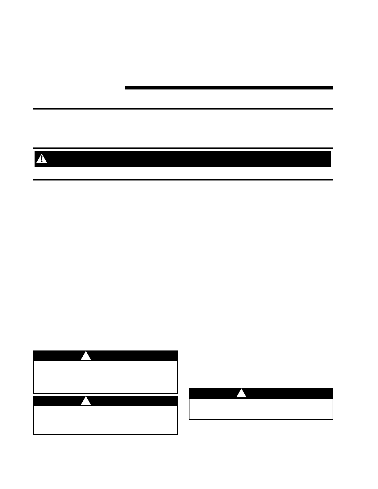
1. Remove the unit economizer/filter access panel, the
evaporator coil and blower access panel, and the electri
cal control box access panel, see Figure 1 on page 2.
2. Filter frame must be installed prior to economizer installa-
tion.
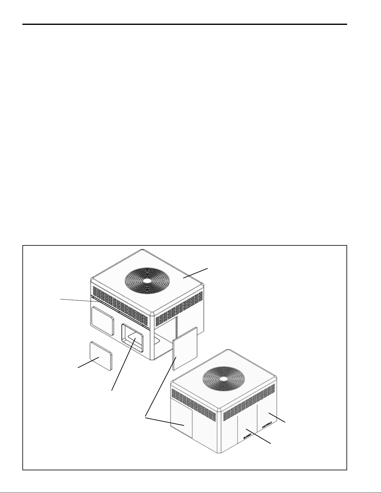
3. Apply two gaskets to horizontal economizer mounting
flanges. See Figure 2 on page 3.
4a. Small Cabinet - BAYECON200A
(TC*,WC*,YC*,DC* *018A to 3036A)
Set the horizontal economizer over the horizontal return
air opening on the unit. The notches in the bottom
flange of the economizer clear the two existing screws
below the return air opening of the unit.
4b. Medium Cabinet Only - - BAYECON201A
(TC*,WC*,YC*,DC* *042A to 3060A)
Apply a gasket to the economizer and slide the top
flange of the economizer under the lip between the top
and bottom sections of the unit. Mate the notches on
WARNING
WARNING
the top flange of the economizer with the existing screws
between the top and bottom sections of the unit. The
notches on the bottom flange of the economizer clear
the two existing screws below the return air opening of
the unit.
CAUTION
!
Use care when inserting the economizer in the return air
compartment, to prevent damaging the foil faced insulation.
Page 2
INSTALLER’S GUIDE
5. Drill three (3) 9/64” holes through the mating holes in
the top flange of economizer and into the unit. Then,
drive three (3) #10 sheet metal screws to secure the top.
6. Drill three (3) 9/64” engagement holes on each side of the
economizer. Then, drive three (3) #10 sheet metal screws
into each side of the economizer to the unit.
7.
Mount the Mixed Air sensor to the left Blower partition
using two sheetmetal screw. See Figure 4, page 4. The 2 yellow
wires will connect to the Economizer wiring harness in a later step.
Install any economizer options (enthalpy sensor or CO2 sensor)
at this time per instructions provided with the sensor.
8. Apply a gasket to the Rain Hood flanges. See Figure 2.
9. Place the Rain Hood over the horizontal return air opening
of the economizer. See Figure 2. Use the #10 sheet metal
screws provided to attach the hood to the economizer.
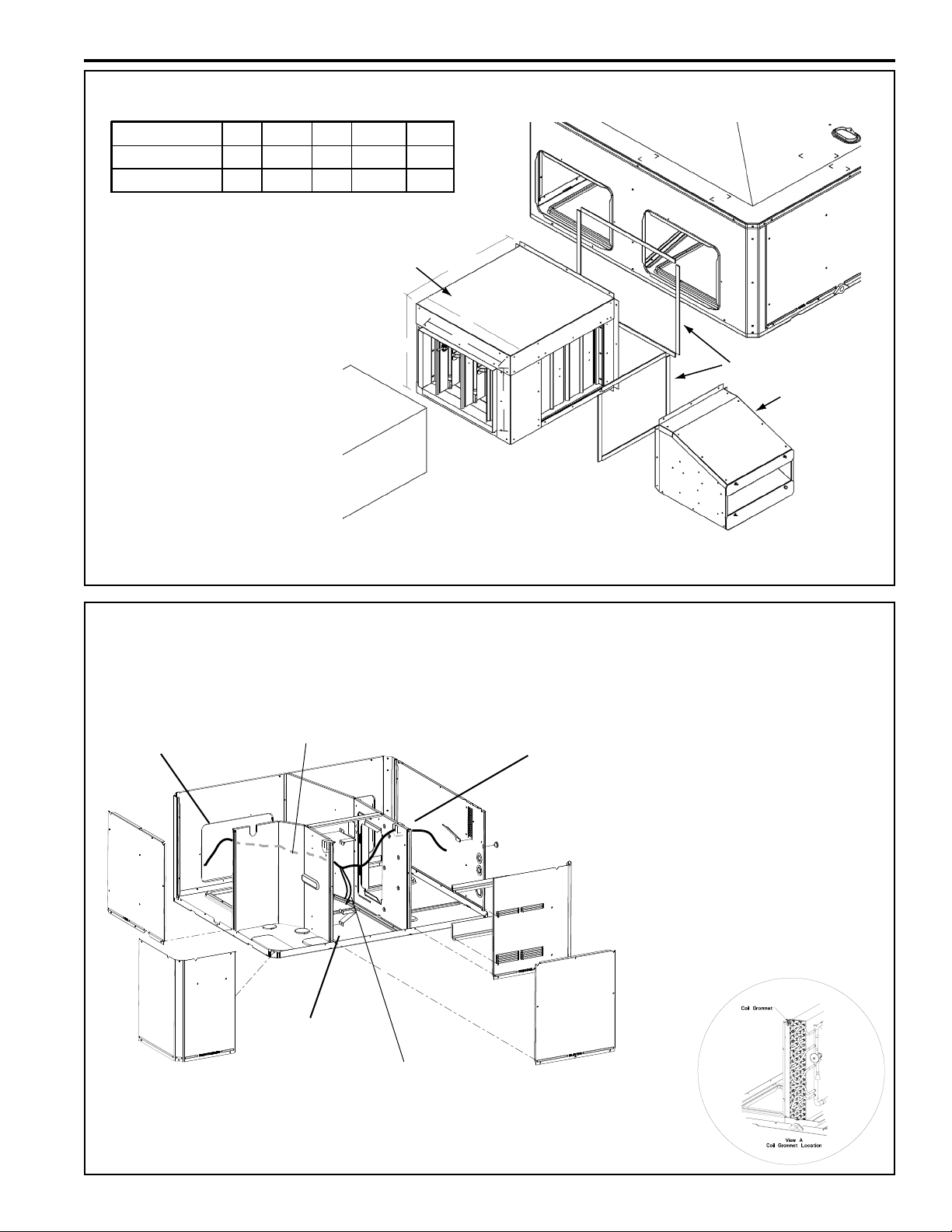
10.
Route the main wiring harness. From the Economizer assembly,
route the main wiring harness to the Mixed Air sensor and to the
Control Box. See Figure 3.
11. Connect the two (2) Mixed Air Sensor wires (pulled from harness)
to the mating pigtail wires (with Stake-Ons) from the Mixed Air
Sensor.
12. In the Control Box, complete the wiring connections per the wiring
diagram on page 5. Secure all wires with wire ties so that there
is no interference with any moving parts in the unit.
IMPORTANT - When the economizer is installed in heat
pump models (WC*), a relay accessory kit
(BAYRLAY004A) is required. Mount relay accessory kit
in unit control box as illustrated on page 6.
13. Attach the return duct to the economizer.
14. Power the economizer and run the checkout procedure on page
7. Make desired adjustments to the controller: set the minimum
occupied damper position, set the outside air (if enthalpy used),
and the IAQ sensor (if used).
15. Replace the unit Coil access panel, the Blower access panel, and the
Control Box access panel.
Top Sealing
Flange
Horizontal
Return Air
Panel
Down Flow
Return Air
Panel
TC, WC, or
YC Unit
Coil Access
Panel
Control Box Access
Panel
Blower Access Panel
Page 2
Figure 1. Remove Panels
Page 3
Horizontal Economizer Assembly
Economizer A B C D E
BAYECON200AA 22" 20" 16-7/8" 15-11/16 11-11/16
BAYECON201AA 26" 22-21/32" 19" 17-11/16 14-11/16
INSTALLER’S GUIDE
NOTE: BAYECON200A economizer only contains two clearance notches in the top flange.
1.) From
EconomizerAssembly,
Pass Wire Harness
Through Coil Grommet. See View A.
Economizer
A
B
C
Duct
D
E
Figure 2. Apply Two Gaskets to Mounting Flanges
2.) Continue Routing
Behind Compressor
Compartment and into
Blower Compartment.
4.) Continue Routing the
Remaining Harness
Through the Grommet
and into the Control Box.
Gaskets (2)
Rain Hood
Location of
Mixed Air Sensor
3.) Pull the 2 Mixed Air Sensor
Wires (with Stake-Ons) from the
Harness and Route Down Near
the Mixed Air Sensor.
Figure 3. Main Wire Harness Routing
Page 3
Page 4

INSTALLER’S GUIDE
1.80"
2.82"
See View ‘A’
View ‘A’ Approximate
Mounting Dimension
Figure 4. Mount Mixed Air Sensor in Blower Compartment
Mount the Mixed Air
Sensor to the partition
using two sheetmetal
screws. See View A
for approximate
positioning.
Page 4
Page 5

INSTALLER’S GUIDE
Figure 5. TC*/YC* Economizer Connection Diagram
Page 5
Page 6

INSTALLER’S GUIDE
Page 6
Figure 6. WC* Economizer Connection Diagram
Page 7

INSTALLER’S GUIDE
CONTROL
CURVE
A
B
C
D
CONTROL POINT
APPROX. F ( C)
AT 50% RH
73 (23)
70 (21)
67 (19)
63 (17)
12 14 16 18 20 22 24 26 28 30 32 34 36 38 40 42
44 46
90
100
80
70
60
50
40
30
20
10
ENTHALPY—BTU PER POUND DRY AIR
85
(29)90(32)95(35)
100
(38)
105
(41)
110
(43)
35
(2)
35
(2)
40
(4)
40
(4)
105
(41)
110
(43)
45
(7)
45
(7)
50
(10)
50
(10)
55
(13)
55
(13)
60
(16)
60
(16)
65
(18)
65
(18)
70
(21)
70
(21)
75
(24)
75
(24)
80
(27)
80
(27)
85
(29)90(32)95(35)
100
(38)
APPROXIMATE DRY BULB TEMPERATURE— F ( C)
A
A
B
B
C
C
D
D
M11681
RELATIVE HUMIDITY (%)
1
1
HIGH LIMIT CURVE FOR W7459D.
Checkout
Operate the motor through its complete open-close
stroke. If necessary, release one of the previously
tightened linkage connections to prevent damage.
Check for proper operation, making sure that the
linkage does not bind and that the motor travels
smoothly throughout its fully open and closed position. Table 1 describes how to drive motors full open
and closed (power connected). If there is excess
length of linkage rod, cut it to size. Make necessary
minor adjustments until desired operation is obtained, and tighten all nuts and set screws. This
motor checkout ensures that:
Table 1. Motor Operation Checkout
MODEL DRIVE MOTOR OPEN DRIVE MOTOR CLOSED SPRING RETURN
M7415 Power to TR and TR1, jumper T and T1.
Disconnect jumper at T or T1 and
disconnect P or P1,if connected.
1. The motor operates the load.
2. The motor responds properly to the controller.
3. There is no binding of the linkage or motor
stalling at any point of travel.
If motor does not operate properly, check for
proper voltage or mechanical binding in linkage or
damper.
If questions arise regarding this product, contact
your distributor or representative.
Disconnect power at TR and TR1.
Single enthalpy: The enthalpy
changeover set point is set to return the
outdoor air damper to minimum position when the enthalpy rises above its
set point. The enthalpy set point scale
markings, located on W7459, are
A,B,C,D; see table for the corresponding control point. The factory-installed
R4 WHITE 620-ohm jumper must be in
place across terminals + and SR.
Figure 7. SINGLE ENTHALPY CHANGEOVER SET POINT
Page 7
Page 8

INSTALLER’S GUIDE
Checkout Procedure Response
A
1. Disconnect power at TR and TR1.
2. Disconnect jumper P to P1.
3. Jumper TR to 1.
4. Jumper T1 to T.
5. If connected, remove C7400 Solid State Enthalpy Sensor
from teminals S0 and +. Ensure factory-installed 620 ohm
resistor is connected to terminals Sr and +.
6. Apply power (24Vac) to terminals TR and TR1
B
1. Disconnect factory-installed 620 ohm resistor from
terminals Sr and +.
C 1. To simulate high and low enthalpy (single enthalpy
sensor) reconnect factory-installed 620 ohm resistor from
termonals Sr and +. Connect 1.2K ohm 4074EJM Checkout
Resistor across terminals So and +.
2. Turn enthalpy setpoint potentiometer to "A".
3. Turn enthalpy setpoint potentiometer to "D".
4. Disconnect the 1.2 K ohm checkout resistor.
D
1. To verify sensor operation, reconnect the + lead of the
outdoor enthalpy sensor to the + terminal of W7459.
2 Connect a DC millimeter between terminal So of the
W7459A and terminal S of the enthalpy sensor. See Fig. 10
(positive meter lead to terminal S of the enthalpy sensor).
3. When using differential enthalpy, check the return air
enthalpy sensor by connecting a DC millimeter between
terminal Sr of the W7459A and terminal S of the return air
enthalpy sensor. (positve meter lead to terminal S of the
enthalpy sensor).
Table 2. Enthalpy Checkout Procedure
LED is off.
Motor is in closed position.
Led turns on, motor drives toward open.
__
LED turns on, indicating low enthalpy.
Motor drives toward open.
LED turns off, indicating high enthalpy.
Motor drives toward closed.
__
__
Millimeter indication is between 3 and 25
mA if sensor is operating properly.
If millimeter indicates zero, the sensor may
be wired backward.
Millimeter indication is between 3 and 25
mA if sensor is operating properly.
If millimeter indicates zero, the sensor may
be wired backward.
Location of Enthalpy Set Point, Minimum Position
and LED
Trane
6200 Troup Highway
Tyler, TX 75707-9010
Page 8
ENTHALPY
CHANGEOVER
SETPOINT
LED LIGHTS
WHEN OUTDOOR
AIR IS SUITABLE
FOR FREE COOLING
MINIMUM DAMPER POSITION ADJUSTMENT
1
IS PRESENT ONLY ON W7459A,D MODELS.
Figure 8. Enthalpy LEDs and Checkout
© 2008 Trane All rights reserved
1
MINIMUM
DAMPER
POSITION
SETTING
M9098B
Meter Location for Checkout and Troubleshooting
W7459
INSERT DC MILLIMETER BETWEEN SO AND S FOR CHECKOUT
1
AND TROUBLESHOOTING.
2
JUMPER USED FOR SINGLE ENTHALPY CONTROL.
The manufacturer has a policy of continuous product and
product data improvement. It reserves the right to
change design and specification without notice.
BC
A
TR
S
O
D
S
R
TR1
+
+
620 OHM
JUMPER
ENTHALPY CHANGEOVER
SETPOINT
2
LED LIGHTS WHEN
OUTDOOR AIR IS SUITABLE
FOR FREE COOLING
1
+
DC
MILLIMETER
+
S
C7400
M9097
 Loading...