

Trane BAYECON103AA, BAYECON103AB, BAYECON104AA, BAYRLAY006A, BAYECON104AB Installer's Manual
Page 1
Installer’s Guide
Down Discharge Economizer and Rain Hood
Model: Used with:
BAYECON103AA/AB 4WCZ6, 4YCZ6, & 4DCZ6036
BAYECON104AA/AB 4WCZ6, 4YCZ6, & 4DCZ6048-060
BAYRLAY006A (Required with 4WCZ6 & 4DCZ6 models)
WARNING: HAZARDOUS VOLTAGE - DISCONNECT POWER BEFORE SERVICING
!
ALL phases of this installation must comply with NATIONAL, STATE AND LOCAL CODES
IMPORTANT ― This document is customer property and is to
remain with this unit. Please return to service information pack upon
completion of work
General
The economizer is a multi-damper design. It is installed in the
return air stream and is connected to the unit low voltage supply
through wire leads. The economizer is fully accessible
through the Coil access panel.
Important: After the Economizer installation you must
install an air lter rack ordered separately. Use:
BAYFLTR101B for 4WCZ6, 4YCZ6, 4DCZ6036
BAYFLTR201B for 4WCZ6, 4YCZ6, 4DCZ6048-060.
When the economizer is installed in 4WCZ6 & 4DCZ6 models,
relay accessory kit BAYRLAY006A is required. Refer to Figure 13
on page 9 to make your relay wiring connections in the Control
Box.
IMPORTANT: In order to maintain a specic minimum fresh
air cfm during each mode of operation, you must order and
install a BAYOSAC001 (outside air control) accessory.
Identify Economizer Kit Contents
Refer to Figures 1 & 2 on page 3 to identify the kit contents.
Inspect Contents
You must report damage and make claims to the transportation company
immediately. Report missing parts to your supplier immediately and
replace with authorized parts only.
WARNING
!
ELECTRICAL SHOCK HAZARD
Open and lock out all unit disconnects prior to accessory
installation or unit maintenance, to prevent injury or death
from electrical shock or contact with moving parts.
Install Economizer Kit
1. Remove Power
Disconnect and verify that power is off.
2. Remove Access Panels
Remove these four (4) access panels (see Figure 3, page 3):
• Control/Heat access panel
• Blower access panel
• Coil access panel
• Downow Return Air panel
3. BAYRLAY006A Installation (Required
for 4WCZ6 & 4DCZ6 units only, 4YCZ6
units skip to step 4)
1. Remove wire harness that came attached to the BAYECON
Logic Module being installed.
IMPORTANT: Do NOT remove the resistors from the
Logic Module. Also, Do NOT remove the YL & YL/BK
wires connected to SO and + on the Logic Module
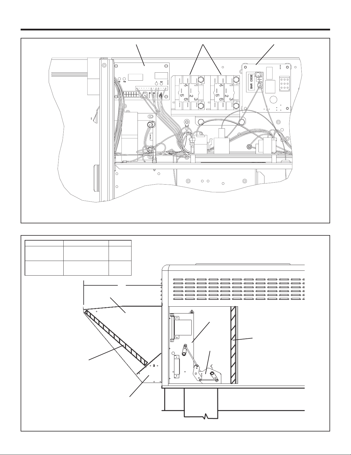
2. Locate the ICMC Board in the upper left hand corner of the
unit control box and the DFC board in the upper center of
the unit control box. See Figure 8, page 6.
3. Using the existing holes in the back of the unit control box,
mount the relay bracket assembly using the 2 screws
supplied with the BAYRLAY0006A Kit. See Figure 8, page
6.
4. Route the BAYRLAY006A wire harness attached to the
relays to the logic module as shown in Figure 11 on page 7.
5. Connect the BAYRLAY006A to the economizer Logic
Module and make the eld connections as shown in Figure 13
on page 9.
18-HE85D1-4
WARNING
!
SAFETY HAZARD
Do not remove end covers from economizer actuator; the
spring-return assembly may release and cause personal
injury.
1
Page 2
INSTALLER’S GUIDE
4. Install Economizer Assembly
NOTE: You must install the lter rack per the instructions
provided with the lter rack after you install the economizer.
CAUTION
!
Use care when inserting the economizer in the return
air compartment, to prevent damaging the foil faced
insulation.
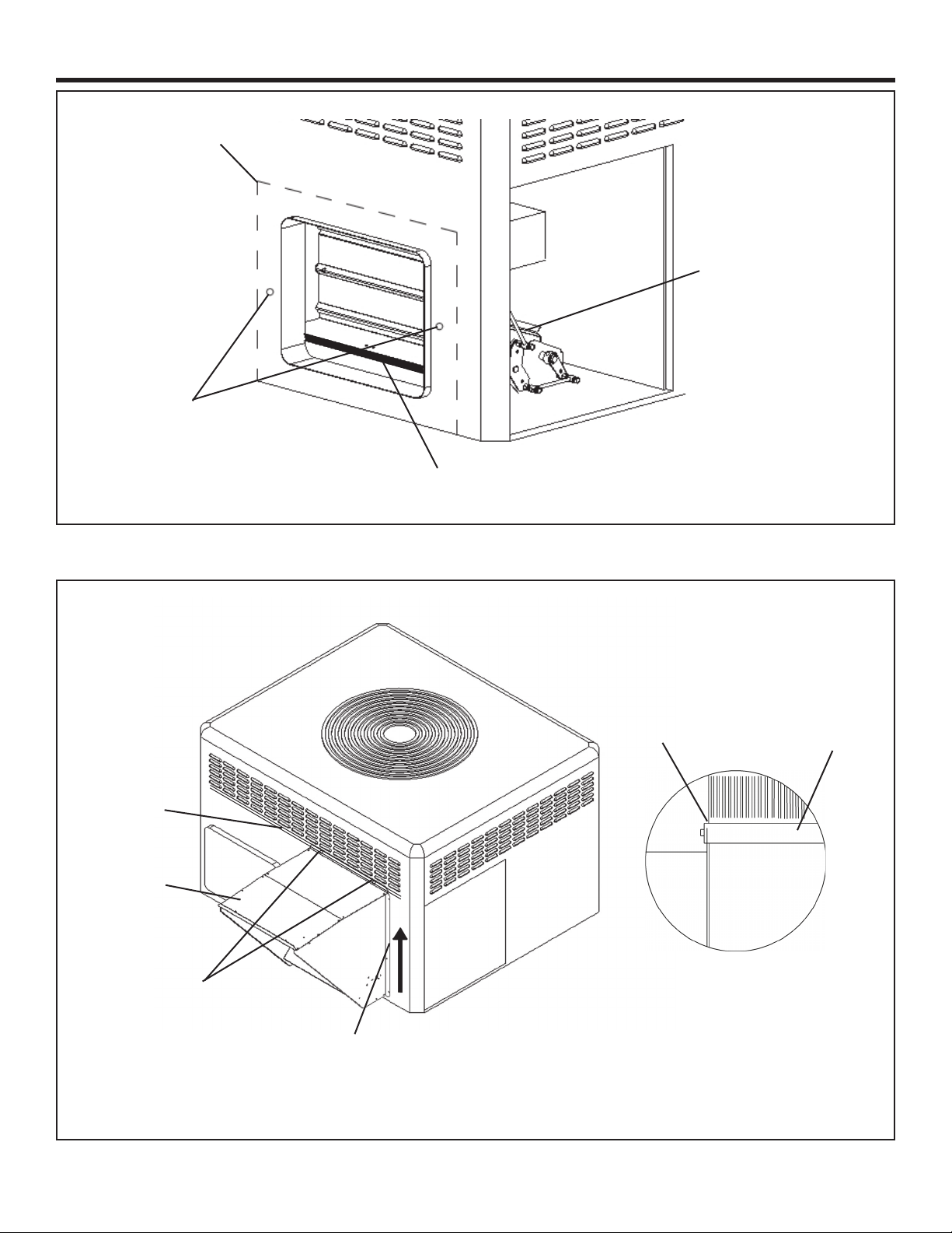
1. The economizer ships with the return air damper folded
up to allow the assembly to t through the Coil opening
in the side of the unit. Insert the economizer assembly into the
unit through the Coil access panel opening. See Figure 4 on
page 4.
2. Swing the return air damper section down so that it rests
on the bottom of the unit. The economizer will sit completely
over the return air opening in the bottom of the unit. See
Figure 5 on page 4. Screw the economizer assembly together
with one assembly screw in the side of the economizer. Check
the linkage rod between the return air dampers to make sure it
is tight.
3. Insert 2 screws through the holes in the front face of the
unit and into the matching attachment holes in the economizer
assembly. See Figure 6 on page 5.
4. Insert a screw through the pre-punched hole in the side
ange of the return air damper and into the mating hole
in the economizer assembly and tighten. See Figure 5 on page
4.
8. Complete Installation (4WCZ6, 4DCZ6, 4YCZ6)
1. In the Control Box, locate the ICMC Board in the upper left hand
corner of the Control Box. Find the YL/RD and YL wires in the 12
pin connector. Leaving enough length of these wires so that the
ends going to the ICMC Board can be stripped, cut these wires in
two. Strip the cut end of the wires going to the ICMC Board and
connect to economizer wires as per hookup diagrams on pages 8
and 9. Cap the ends of the Yellow and Yellow/Red wires not
being hooked up. Secure all wires with wire ties so that there is no
interference with any moving parts in the unit.
CAUTION
!
Be certain to cap the ends of the cut YL/RD and YL wires
that are not being connected to an accessory or the unit to
reduce the risk of a short.
2. In the Control Box, complete the wiring connections per the
appropriate wiring diagram on pages 8 and 9. Secure all wires so
that there is no interference with any moving parts in the unit.
3. Power the economizer and run the checkout procedure on page
10. Make desired adjustments to the controller setting the
minimum occupied damper position, the outside air setting (if
enthalpy control used).
4. Replace the unit Coil access panel, the Blower access panel, and
the Control/Heat access panel.
5. Install Rain Hood Assembly
1. Locate the rainhood assembly, which includes the relief damper
and the mist eliminator. The back of the hood side mating anges
need to be gasketed (gaskets included in kit). Loosen the right two
(2) screws on the unit’s top sealing ange above the economizer.
See Figure 7 on page 5.
2. Slide the top ange of the hood underneath the unit’s top sealing
ange. Drive two self tapping screws into the keyhole openings on
the side anges of the hood. Tighten the two (2) screws on the top
sealing ange and the screws on the hood side anges. See
Figures 7 and 9.
6. Mount Mixed Air Sensor
1. Mount the Mixed Air sensor (with wiring) to the left Blower
partition using two sheetmetal screws. See Figure 10, page 7. The
male tabs on the Yellow and Yellow/Black wires will connect to
the Economizer wiring harness in a later step.
2. Enthalpy SensorIf used, install this option at this time per
instructions provided in the sensor kit.
7. Route Main Wiring
1. From the Economizer assembly, pass the wire harness through the
coil grommet. See Figure 11 (view A) on page 7. Continue routing
the harness behind the Compressor compartment and into the
Blower compartment.
2. Continue routing the remaining harness through the grommet in
the Control Box partition and into the Control Box.
2
Page 3
INSTALLER’S GUIDE
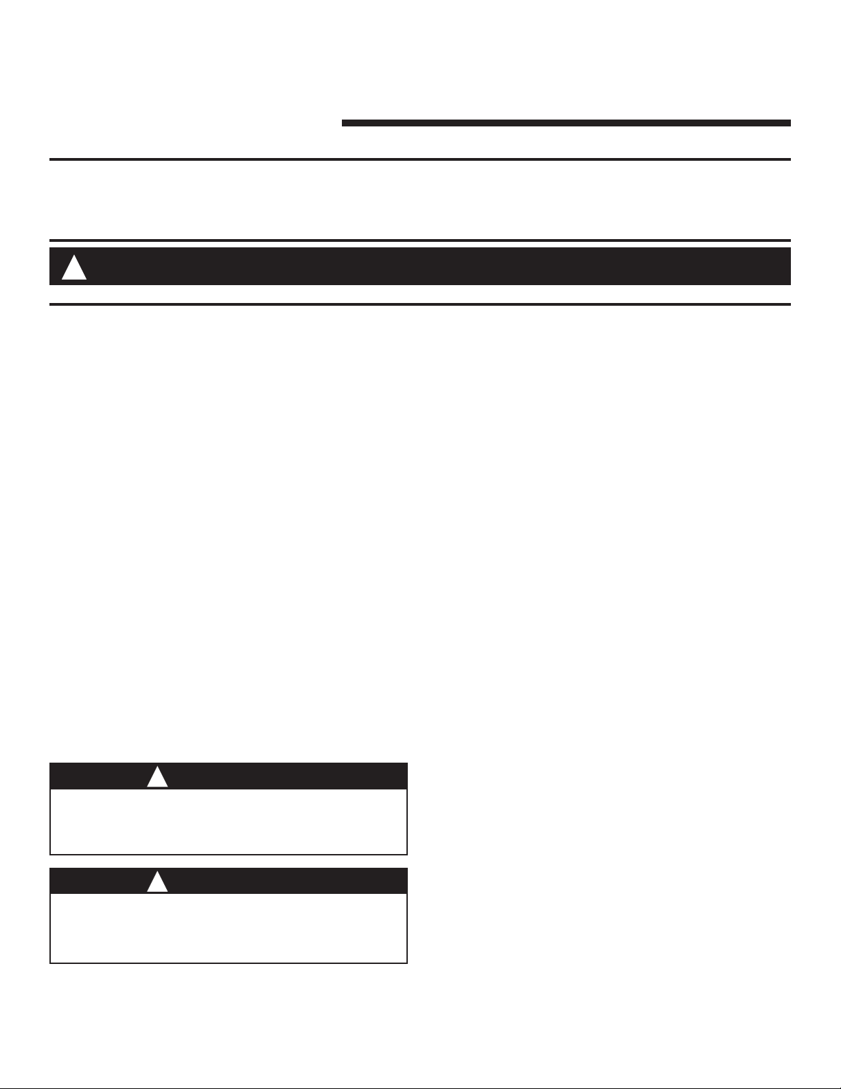
Mixed Air Sensor
Logic
Module
Return Air Damper
Flange Screw and
two (2) Mixed Air
Sensor
Sheetmetal Screws
(not shown)
Figure 1. BAYECON103AA/AB Economizer Kit Components
Economizer Assembly
Mist
Eliminator
(Filter)
Rainhood Assembly
4WCZ6, 4YCZ6, & 4DCZ6036
Logic
Module
Economizer Assembly
Return Air Damper
Flange Screw and
two (2) Mixed Air
Sensor
Sheetmetal Screws
(not shown)
Rainhood Assembly
Figure 2. BAYECON104AA/AB Economizer Kit Components
4WCZ6, 4YCZ6, & 4DCZ6048-060
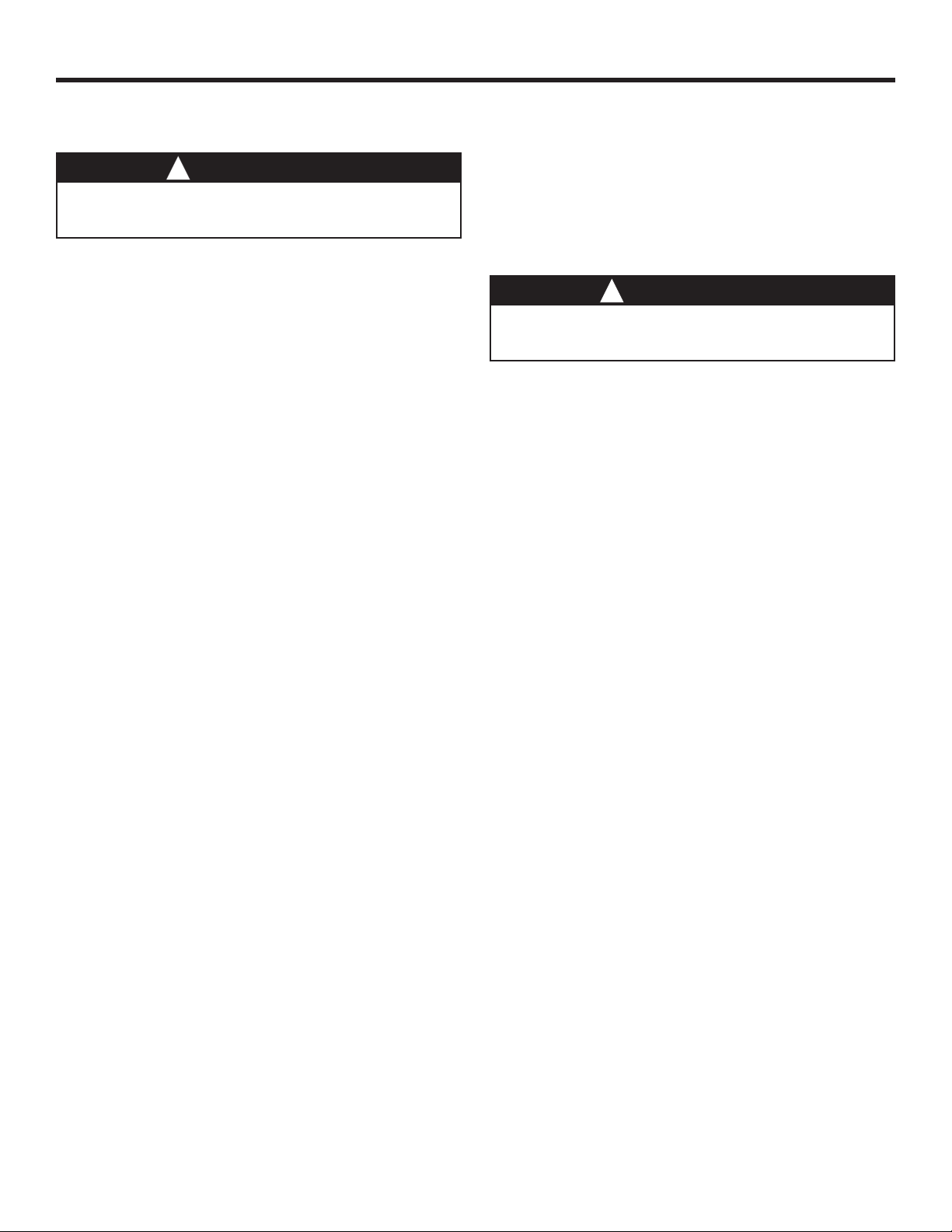
4WCZ6, 4YCZ6, or 4DCZ6 Unit
Mixed Air Sensor
Mist
Eliminator
(Filter)
Top Sealing
Flange
Horizontal
Return Air
Panel
Down Flow
Return Air
Panel
Coils Access
Panel
Control Box
Access Panel
Blower Access Panel
Figure 3. Remove Panels
3
Page 4
INSTALLER’S GUIDE
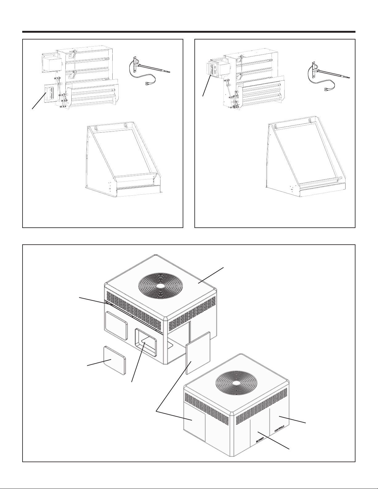
4WCZ6, 4YCZ6, or 4DCZ6 Unit
Insert economizer
in folded shipping
position
Economizer
actuator and
Logic Module
Economizer
Dry bulb outside air
temperature sensor
Figure 4. Insert Economizer in Shipping Position
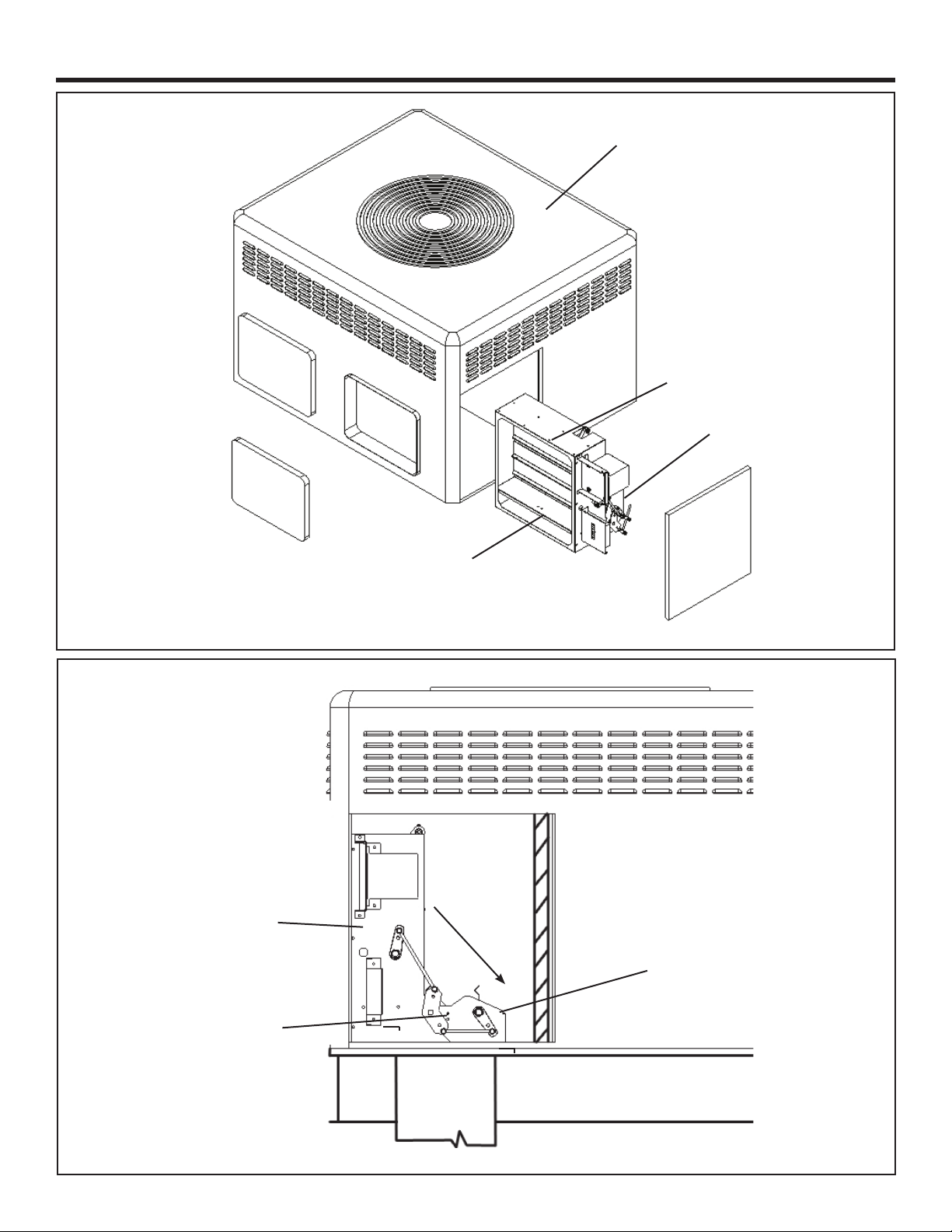
1.) Swing
Down
Return Air
Damper
Return Air Damper
2.) Insert Assembly
Screw
Figure 5. Swing Down and Set Economizer Return Damper
4
Page 5
Economizer outline
Install two (2)
screws into holes.
Leave extended
from unit 1/2”
INSTALLER’S GUIDE
Economizer and
Return Air Damper
Apply gasket between damper assembly and hood
Figure 6. Start Economizer’s Front Mounting Screws
Unit’s top sealing
ange
Economizer Rain
Hood
1. Loosen the two
(2) screws to allow
hood to slide under
top sealing ange of
the unit.
2. Drive six (6) self
tapping screws into
the keyhole openings
on each side of hood
anges.
3. Tighten the two
(2) top screws and
the two (2) side
screws
Figure 7. Mounting Rain Hood
Top ange of hood
slides under HVAC
unit’s top sealing
ange
Hood
HVAC unit’s top
sealing ange
HVAC unit
Detail
5
Page 6
INSTALLER’S GUIDE
ICMC Board Relays
DFC
Economizer Unit Application Models A
BAYECON103AA/AB
BAYECON104AA/AB
4WCZ6036A
4DCZ6036A
4YCZ6036A
4WCZ6048-060A
4DCZ6048-060A
4YCZ6048-060A
Economizer Rain
Hood
Mist Eliminator
(lter)
Figure 8. Mount BAYRLAY006A
20 1/8”
24 3/8”
A
Outside air
dampers
Return air
dampers
Required lter kit,
order separately
Relief Damper
Return Duct
Roofcurb
Figure 9. Rain Hood, Economizer, and Filter
6
Page 7

1.80”
INSTALLER’S GUIDE
2.82”
View ‘A’ Approximate
Mounting Dimensions
1.) From economizer
assembly, pass wire
harness through coil
Grommet. See View A.
See View ‘A’
Mount the Mixed Air
Sensor to the partition
using two (2) sheetmetal
screws. See view A for
approximate positioning
Figure 10. Mount Mixed Air Sensor in Blower Compartment
2.) Continue routing
behind compressor
compartment and into
Blower Compartment.
3.) Pull the two (2) Mixed Air
Sensor wires (with female quick
connects) from the harness and
route down near the Mixed Air
Sensor. Connect to sensor
pigtail wire leads.
4.) Continue Routing the
Remaining Harness
Through the Grommet
and into the Control Box.
Location of
Mixed Air Sensor
Figure 11. Main Wire Harness Routing
Coil Grommet
View A
Coil Grommet Location
7
Page 8

INSTALLER’S GUIDE
A
A
A
A
Wiring Diagram for Economizer Using a Honeywell W7459 Logic
Figure 12. 4YCZ6 Economizer Connection Diagram
IMPORTANT-Retain this wiring diagram; please return this document to service information pack upon completion of work.
8
Page 9

INSTALLER’S GUIDE
Wiring Diagram for Economizer Using a Honeywell W7459 Logic
AAA
A
Figure 13. 4WCZ6 & 4DCZ6 Economizer Connection Diagram
IMPORTANT-Retain this wiring diagram; please return this document to service information pack upon completion of work.
9
Page 10

INSTALLER’S GUIDE
Wiring Diagram for Economizer Using a Honeywell W7212 Logic
A
A
A
A
Figure 14. 4WCZ6 & 4DCZ6 Economizer Connection Diagram
IMPORTANT-Retain this wiring diagram; please return this document to service information pack upon completion of work.
10
Page 11

INSTALLER’S GUIDE
Wiring Diagram for Economizer Using a Honeywell W7212 Logic
A
A
A
A
Figure 15. 4YCZ6 Economizer Connection Diagram
IMPORTANT-Retain this wiring diagram; please return this document to service information pack upon completion of work.
11
Page 12

INSTALLER’S GUIDE
12
85
100
105
110
(43)
0
(43)
1
HIGH LIMIT CURVE FOR W7459D.
Sequence Of Operation
NOTE: A (G) signal is required for the economizer to operate. As
shipped, the economizer will not operate when there is a signal for
Heating Modes utilizing gas heat.
Fan Only (G): When the thermostat sends a signal for fan only (G),
the economizer will open to the minimum position setting regardless
of the outdoor air conditions and the indoor blower will operate at
approximately 50% airow.
Heating (W1), (W2), (Y1, Y2 on Heat Pump or Dual Fuel
Models): When the thermostat sends a signal for auxiliary heat (G)
+ (W1) or rst stage heat (G) + (Y1,Y2), the economizer will open
to the minimum position setting. When the ambient temperature may
be below 70F, the economizer will not fully open to the economizing
position, when there is a signal for heat. In order to receive fresh air
and open the dampers to the minimum position setting, you must
provide a G signal to the unit from the thermostat or comfort control
being used.
FREE COOLING NOT AVAILABLE: When the outdoor air
conditions are not sufcient for “Free Cooling” the Economizer will
open to the minimum position setting only and the unit will
function.
FREE COOLING AVAILABLE:
1st Stage Cooling (Y1) + (O for Heat Pumps and Dual Fuel
models): When outdoor air conditions are sufcient for “Free
Cooling” and the thermostat sends a signal for 1st stage cooling (G) +
(Y1) + (O for Heat Pumps and Dual Fuel models), the economizer
will modulate accordingly and the indoor blower will run at
approximately 70% airow.
2nd Stage Cooling (Y1) + (Y2) + (O for Heat Pumps and Dual
Fuel models): When outdoor air conditions are sufcient for “Free
Cooling” and the thermostat sends a signal for 2nd stage cooling (G) +
(Y1) + (Y2) + (O for Heat Pumps and Dual Fuel models), the
economizer will modulate accordingly, the compressor will operate
on low speed, and the indoor blower will operate at 100% airow.
Unit “OFF” Mode
When the economizer is not receiving a 24V signal to the TR
terminal, or if power is disconnected to the unit, the dampers will be
fully closed to the outside air and fully open to the return air.
NOTE: Free Cooling refers to the process of circulating
unconditioned outside air, without operating the compressor, to cool
the structure.
5A. CHECKOUT - For Units using a Honeywell
W7459 Control, Only.
Operate the motor through its complete open-close stroke. Check
for proper operation, making sure that the linkage does not bind
and that the motor travels smoothly throughout its fully open
and closed position. Table 1 describes how to drive the motor to
the full open and full closed positions (power connected). Make
necessary minor adjustments until desired operation is obtained,
and tighten all nuts and set screws. This motor checkout ensures
that:
1. The motor operates the load.
2. The motor responds properly to the controller.
3. There is no binding of the linkage or motor stalling at any
point of travel.
If motor does not operate properly, check for proper voltage or
mechanical binding in linkage or damper.
If questions arise regarding this product, contact your distributor
or representative.
Single enthalpy: The enthalpy
changeover set point is set to return
the outdoor air damper to minimum
position when the enthalpy rises above
its set point. The enthalpy set point
scale markings, located on W7459, are
A,B,C,D; see table for the corresponding
control point. The factory-installed R4
CONTROL
CURVE
A 73 (23)
B 70 (21)
C 67 (19)
D 63 (17)
CONTROL POINT
APPROX. F (C)
AT 50% RH
44 46
(29)90(32)95(35)
80
(27)
75
(24)
(38)
(41)
WHITE 620-ohm jumper must be in place
across terminals + and SR.
ENTHALPY—BTU PER POUND DRY AIR
55
(13)
50
C
14 16 18 20 22 24 26 28 30 32 34 36 38 40 42
35
(2)
35
(2)
APPROXIMATE DRY BULB TEMPERATURE— F ( C)
(10)
45
D
(7)
40
(4)
40
45
50
(4)
55
(7)
(10)
(13)
70
(21)
100
90
65
80
(18)
60
(16)
A
B
60
(16)
70
60
C
D
65
70
75
(18)
(21)
(24)
(27)
50
A
B
80
85
(29)90(32)95(35)
40
1
RELATIVE HUMIDITY (%)
30
20
10
105
11
100
(41)
(38)
M11681
12
Figure 16. Single Enthalpy Changeover Set Point
Page 13

INSTALLER’S GUIDE
Table 1. Motor Operation Checkout - W7459 Control Only
MODEL DRIVE MOTOR OPEN DRIVE MOTOR CLOSED SPRING RETURN
M7415 Power to TR and TR1, jumper T and T1
Table 2. Enthalpy Checkout Procedure - W7459 Control
Checkout Procedure Response
A 1. Disconnect power at TR and TR1.
2. Disconnect jumper P to P1.
3. Jumper TR to 1.
4. Jumper T1 to T.
5. If connected, remove C7400 Solid State Enthalpy Sensor from terminals S0 and +. Ensure factory-installed 620 ohm resistor is connected to terminals Sr and +.
6. Apply power (24Vac) to terminals TR and TR1
B 1. Disconnect factory-installed 620 ohm resistor from terminals Sr and
+
C 1. To simulate high and low enthalpy (single enthalpy sensor) re-
connect factory-installed 620 ohm resistor from terminals Sr and +.
Connect 1.2K ohm 4074EJM Checkout Resistor across terminals So
and +.
2. Turn enthalpy setpoint potentiometer to "A".
3. Turn enthalpy setpoint potentiometer to "D".
4. Disconnect the 1.2K ohm checkout resistor
D 1. To verify sensor operation, reconnect the + lead of the outdoor
enthalpy sensor to the + terminal of W7459.
2. Connect a DC multimeter between terminal So of the W7459A and
terminal S of the enthalpy sensor. See Fig. 17 (positive meter lead to
terminal S of the enthalpy sensor).
3. When using differential enthalpy, check the return air enthalpy
sensor by connecting a DC multimeter between terminal Sr of the
W7459A and terminal S of the return air enthalpy sensor. (positive
meter lead to terminal S of the enthalpy sensor).
Disconnect jumper at T or T1 and
disconnect P or P1, if connected
LED is off.
Motor is in closed position.
LED turns on, motor drives toward open.
―
LED turns on, indicating low enthalpy.
Motor drives toward open.
LED turns off, indicating high enthalpy.
Motor drives toward closed.
―
―
Multimeter indication is between 3 and 25 mA if
sensor is operating properly.
If multimeter indicates zero, the sensor may be
wired backward.
Multimeter indication is between 3 and 25 mA if
sensor is operating properly.
If multimeter indicates zero, the sensor may be
wired backward.
Disconnect power at TR and TR1
13
Page 14

INSTALLER’S GUIDE
OUTDOOR AIR IS SUITABLE
IS PRESENT ONLY ON W7459A,D MODELS.
Location of Enthalpy Set Point, Minimum Position and LED Meter Location for Checkout and Troubleshooting
14
MINIMUM DAMPER POSITION ADJUSTMENT
1
Table 3. Temp vs. OHM Values for MAS (Mixed Air Sensor)
Temp F Temp C R(K OHMS) DC Volts
33.8 1 9.576 3.910
35.6 2 9.092 3.882
37.4 3 8.636 3.894
39.2 4 8.204 3.863
41.0 5 7.796 3.829
42.8 6 7.412 3.790
44.6 7 7.048 3.749
46.4 8 6.705 3.713
48.2 9 6.380 3.674
50.0 10 6.073 3.634
51.8 11 5.782 3.590
53.6 12 5.507 3.550
55.4 13 5.247 3.507
57.2 14 5.000 3.420
59.0 15 4.767 3.373
60.8 16 4.545 3.328
62.6 17 4.335 3.283
64.4 18 4.136 3.239
66.2 19 3.948 3.180
68.0 20 3.769 3.157
69.8 21 3.599 3.118
71.6 22 3.437 3.080
73.4 23 3.284 3.034
75.2 24 3.138 3.007
77.0 25 3.000 2.971
78.8 26 2.869 2.932
80.6 27 2.744 2.896
82.4 28 2.625 2.860
84.2 29 2.512 2.824
86.0 30 2.404 2.787
87.8 31 2.301 2.750
89.6 32 2.204 2.714
91.4 33 2.111 2.676
93.2 34 2.023 2.639
95.0 35 1.938 2.600
96.8 36 1.858 2.561
98.6 37 1.781 2.526
100.4 38 1.708 2.484
ENTHALPY
CHANGEOVER
SETPOINT
MINIMUM
DAMPER
POSITION
1
SETTING
LED LIGHTS
WHEN OUTDOOR
AIR IS SUITABLE
FOR FREE COOLING
M9098B
W7459
BC
A
INSERT DC MILLIAMMETER BETWEEN SO AND S FOR CHECKOUT
1
2
MULTIMETER
AND TROUBLESHOOTING.
JUMPER USED FOR SINGLE ENTHALPY CONTROL.
Figure 17. Enthalpy LEDs and Checkout
Temp vs. OHM for MAS (Mixed Air Sensor)
TR1
TR
S
O
D
S
R
+
+
2
620 OHM
JUMPER
LED LIGHTS WHEN
FOR FREE COOLING
ENTHALPY CHANGEOVER
SETPOINT
+
1
S
+
C7400
DC
MULTIMETER
MILLIMETER
M9097
Page 15

INSTALLER’S GUIDE
M20612
DC VOL
W7212
AQ1 FOR
5B. CHECKOUT - For Units with a Honeywell W7212 Control, Only. See 5A for W7459
CHECKOUT AND
TROUBLESHOOTING
Checkout requires a 9V battery, 620 ohm, 1.2K ohm, 5.6K ohm,
and 6.8K ohm resistors. Use Table 4 and Fig. 18 for checkout.
CAUTION
!
Equipment Damage Hazard.
Excessive force can damage potentiometer
controls.
Use a small screwdriver when adjusting enthalpy
changeover and minimum damper position controls.
EXH
DCV
Free
Cool
EXH
Set
10V
2V
Min
Pos
Open
DCV
Max
2V
10V
DCV
Set
2V
10V
B
C
A
D
N1
N
P1
P
T1
1
TMETER
T
+
AQ1
AQ
S
C7400
+
2
1
INSERT DC VOLTMETER BETWEEN AQ AND
CHECKOUT AND TROUBLESHOOTING.
2
JUMPER USED FOR SINGLE ENTHALPY CONTROL.
SO+
SO
SR+
SR
620 OHM RESISTOR
Fig. 18. Meter location for checkout and
troubleshooting (W7212 shown).
Table 4. Checkout for W7212, W7213, W7214 Economizer Connected to Honeywell Actuator
Step Checkout Procedure Proper Response
1. CHECKOUT PREPARATION FOR ECONOMIZING ONLY
Disconnect power at TR and TR1 All LED are off; Exhaust Fan contacts are open
Disconnect devices at P and P1
Jumper P to P1 (defaults to on board MIN POS potentiometer).
Place 5.6K ohm resistor across T and T1 (Blue sleeve-provides input to
economizer that the MAT is between 50-55F).
Jumper TR to 1 (call for cooling from the thermostat).
W7212 only jumper TR to N (places economizer in occupied mode).
If connected, remove C7400 Enthalpy Sensor from terminals SO and +.
Connect 1.2K ohm, from 4074EJM Checkout Resistor kit, (purple sleeve)
across terminals SO and + (makes OA enthalpy high).
Place 620 ohm resistor (white sleeve) across SR and + (makes return
enthalpy lower than OA).
Set MIN POS and DCV MAX potentiometers fully CCW.
Turn DCV setpoint potentiometer mid position (this sets the DCV
ventilation at approximately 1000 ppm).
Turn exhaust potentiometer to mid position (motor will be approximately
50% open when the exhaust fan contacts make).
Set enthalpy potentiometer to D.
W7214 only Jumper TR to O.
Apply power (24 Vac) to terminals TR and TR1
15
Page 16

INSTALLER’S GUIDE
Table 4. Checkout for W7212, W7213, W7214 Economizer Connected to Honeywell Actuator (Cont.)
Step Checkout Procedure Proper Response
2. DIFFERENTIAL ENTHALPY
Execute stop one, Checkout Preparation.
Turn DCV MAX to mid position.
Place 620 ohm resistor across SO and + (white sleeve resistor
makes OA enthalpy low).
Place 1.2K ohm resistor across SR and + (purple sleeve resistor
makes RA enthalpy high).
Remove 620 ohm resistor from SO and +. Free cool LED turn off; motor drives closed
3. SINGLE ENTHALPY
Execute stop one, Checkout Preparation.
Turn DCV MAX to mid position.
Set enthalpy potentiometer to A (fully CCW). Free cool LED turns on; motor drives to approximately 45
Set enthalpy potentiometer to D or E for W7212C (fully CW). Free cool LED turns off; motor drives closed.
4. DCV AND EXHAUST
Execute step one, Checkout Preparation.
LED for both DCV and Exhaust should be off.
Turn DCV MAX to mid position. Motor drives to mid position, 45 degrees open.
Turn MIN POS fully CW. Motor drives fully open.
Turn MIN POS and DCV MAX to fully CCW. Motor drives closed.
Turn DCV MAX to mid position.
Connect 9V battery positive to AQ and negative to AQ1.
Remove jumper from N terminal (economizer goes into not occupied mode).
Adjust DCV MAX towards CW. Motor will move to position set by DCV MAX pot.
Adjust DCV MAX to fully CCW. Motor will drive closed.
Reconnect jumper to N terminal.
Adjust DCV MAX and MIN POS pots. Motor will drive to the most open position of the pots.
Adjust DCV MAX and MIN POS pots to fully CCW.
Remove power from N terminal adjust MIN POS towards CW. Motor should not move.
Adjust DCV MAX towards CW. Motor will move to position set by DCV MAX pot.
5. MINIMUM AND MAXIMUM POSITION
Execute stop one, Checkout Preparation.
Connect 9V battery positive to AQ and negative to AQ1. Adjust
DCV MAX potentiometer to mid position.
Turn DCV maximum position potentiometer to fully CCW. Actuator drives fully closed.
Turn minimum position potentiometer to midpoint. Actuator drives to 45 degrees open.
Turn minimum position potentiometer fully CW. Actuator drives fully open.
Turn MIN POS to fully CCW. Actuator drives fully closed.
W7212: Remove jumper from TR and N. Actuator drives fully closed.
W7214: Jumper TR to O.
6. MIXED AIR INPUT
Execute stop one, Checkout Preparation.
Turn DCV MAX to mid position; set enthalpy potentiometer to A. Free cool LED turns on.
Remove 5.6K ohm resistor (green sleeve) and place jumper from
T and T1.
Remove jumper from T and T1 and leave open. Actuator drives fully closed.
16
―
Free cool LED turn on; motor drives to approximately 45
degrees (half) open.
―
degrees (half) open.
―
LED for both DCV and Exhaust turn on.
Actuator drives to 45 degrees open.
Motor remains at 45 degrees open.
―
DCV LED turns on. Actuator drives to 45 degrees open.
―
Actuator drives to 45 degrees open.
Actuator drives to 45 degrees open.
Page 17

INSTALLER’S GUIDE
17
Page 18

INSTALLER’S GUIDE
Trane
6200 Troup Highway
Tyler, TX 75707-9010 © 2010 Trane
18
The manufacturer has a policy of continuous product and
product data improvement. It reserves the right to change
design and specication without notice.
 Loading...