

INSTALLER'S GUIDE
▲
WARNING
!
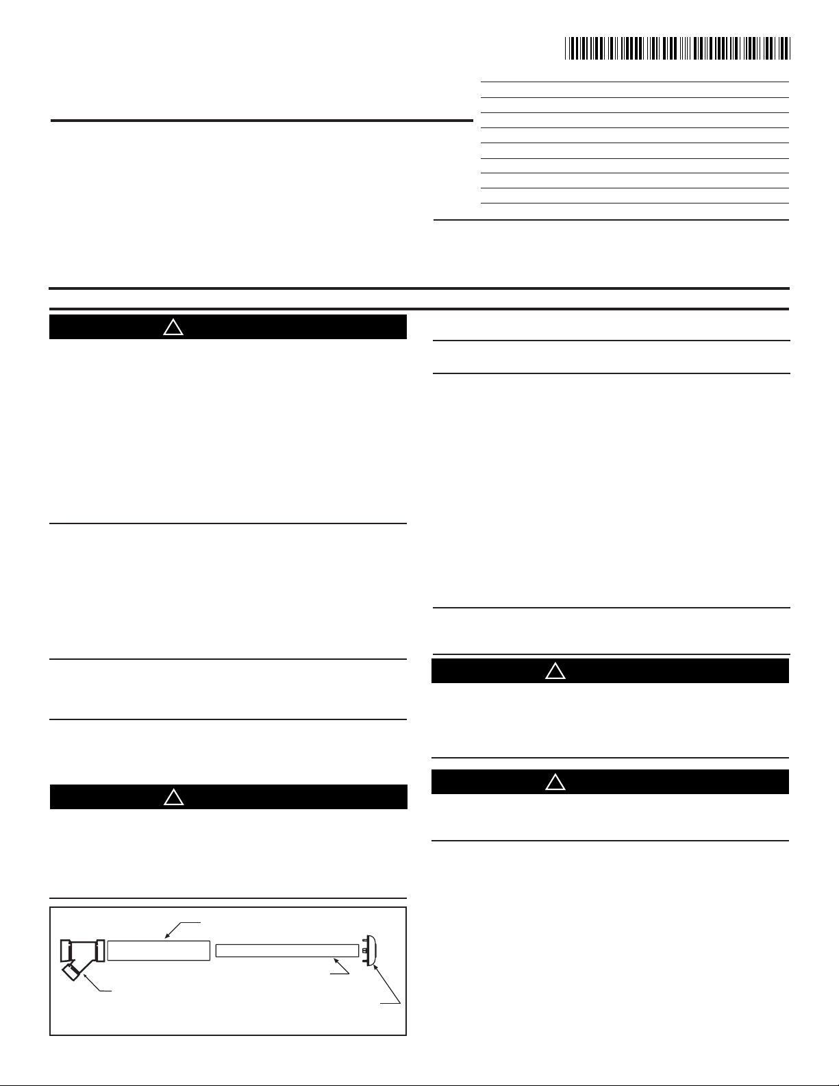
RAIN CAP
4" SDR-26 PIPE
2-1/2" SDR-26 PIPE
WYE- CONCENTRIC FITTING
▲
WARNING
!
▲
WARNING
!
▲
WARNING
!
ALL phases of this installation must comply with
NATIONAL, STATE AND LOCAL CODES.
Model:
BAYAIR30AVENTA
Concentric Vent Kit for
Condensing Furnaces and Boilers
For use with *UH, *DH, M95, *UY, *DY, *UX, *DX,
*UC, *DC model Furnaces and TGCW130A90M0A
and TGXWW130A90M0A boilers
* may be A or T or C
IMPORTANT — This Document is customer proper ty and is to remain with this unit. Please return to service information pack upon completion of work.
NOTE:
Canada requires that all Category IV heating appliances use
venting material that meets ULC S636. This kit does not meet
these requirements and cannot be used.
DO NOT APPLY TO A NON-CONDENSING FURNACE.
Library
Product Section
Product
Model
Literature Type
Sequence
Date
File No.
Supersedes
18-CH34D1-7
Service Literature
Unitary
Unitary Accessories
Vents
Installer's Guide
02/12
18-CH34D1-7
18-CH34D1-56
0
INSTALLATION OR REPAIRS MADE BY UNQUALIFIED
PERSONS CAN RESULT IN HAZARDS TO YOU AND OTHERS. INSTALLATION MUST CONFORM WITH LOCAL CODES
OR, IN THE ABSENCE OF LOCAL CODES, WITH CODES OF
THE COUNTRY HAVING JURISDICTION. THE INFORMATION
CONTAINED IN THESE INSTRUCTIONS IS INTENDED FOR
USE BY A QUALIFIED SERVICE TECHNICIAN FAMILIAR WITH
SAFETY PROCEDURES AND EQUIPPED WITH THE PROPER
TOOLS AND TEST INSTRUMENTS. FAILURE TO CAREFULLLY READ AND FOLLOW ALL INSTRUCTIONS IN THESE
INSTRUCTIONS CAN RESULT IN FURNACE OR BOILER
MALFUNCTION, PROPERTY DAMAGE, PERSONAL INJURY
AND/ OR DEATH.
NOTE: Codes and local utility requirements governing the
installation of gas fired equipment, wiring, plumbing, and
flue connections must be adhered to. In the absence of local
codes, the installation must conform with the Nation Fuel
Gas Code ANSI Z223.1 "latest edition", or CAN/ CGA B149
Installation Codes. The latest code may be obtained from the
American Gas Association Laboratories 400 N. Capitol St.
NW, Washington D.C. 20001, 1-800-699-9277 or www.aga.
com
NOTE: Read the Installer's Guide before starting the installation. Refer to the Furnace or boiler Installer's Guide for
equivalent vent lengths. The BAYAIR30AVENTA is 5 equivalent feet.
INTRODUCTION
This Installer's Guide covers installation of the concentric vent
kit on all gas fired direct vent condensing furnaces.
NOTE: If these instructions differ from those packaged with
the furnace or boiler, follow these instructions.
DESCRIPTION AND USAGE
Kit Contents:
1 — Rain cap
1 — 4" Diameter SDR-26 Pipe, 23.75" Long
1 — 21/2" Diameter SDR-26 Pipe, 33.12"
1 — Wye concentric Fitting
Only one vent kit per each furnace or boiler is allowed.
Vent kit is for 2, 2-1/2 or 3 in. diameter pipe systems, (See
Figures 3, 4, 5, and 6 for the different applications.) Both
the combustion air and vent pipes must attach to the vent
kit. The vent kit must terminate outside of the structure and
should be installed vertically as shown in Figures 3 and 4, or
horizontal as shown in Figures 5 and 6.
NOTE: The roof vent location is preferred since it is less
susceptible to damage, has reduced chances to intake contaminants, and vent vapors are less visible.
THIS VENT KIT IS ONLY TO BE USED FOR VENTING CATEGORY IV FURNACES AND CONDENSING BOILERS. DO
NOT USE TO VENT CATEGORY I, II OR III VENT FURNACES
OR BOILERS. FAILURE TO FOLLOW THIS WARNING COULD
RESULT IN FIRE, PERSONAL INJURY OR DEATH.
INSTALLING AND SERVICING HEATING EQUIPMENT CAN
BE HAZARDOUS DUE TO GAS AND ELECTRICAL COMPONENTS. ONLY TRAINED PERSONNEL SHOULD INSTALL OR
SERVICE HEATING EQUIPMENT. FAILURE TO FOLLOW THIS
WARNING CAN RESULT IN PRODUCT DAMAGE, PERSONAL
INJURY AND/OR DEATH.
1
© 2012 Trane All Rights reserved
CONCENTRIC VENT KIT
DISCONNECT POWER SUPPLY BEFORE BEGINNING INSTALLATION TO PREVENT PERSONAL INJURY OR DEATH
FROM ELECTRICAL SHOCK AND EQUIPMENT DAMAGE.
Field supplied pipe and fittings are required to complete the
installation.
The combustion air and vent pipe and fittings must conform to
American National Standards Institute (ANSI) and American
Society for Testing and Materials (ASTM) standards D1785
(schedule-40 PVC), D2665 (PVC-DWV), D2441 (SDR-21 and
SDR-26 PVC), D2661 (ABS-DWV), or F628 (schedule-40 ABS).
Pipe cement and primer must conform to ASTM standards D2564
(PVC) or D2235 (ABS). In Canada, construct all combustion air
and vent pipes for this unit of CSA or ULC certified schedule-40
PVC/ABS-DWV pipe and pipe cement.
INSTALLER'S GUIDE
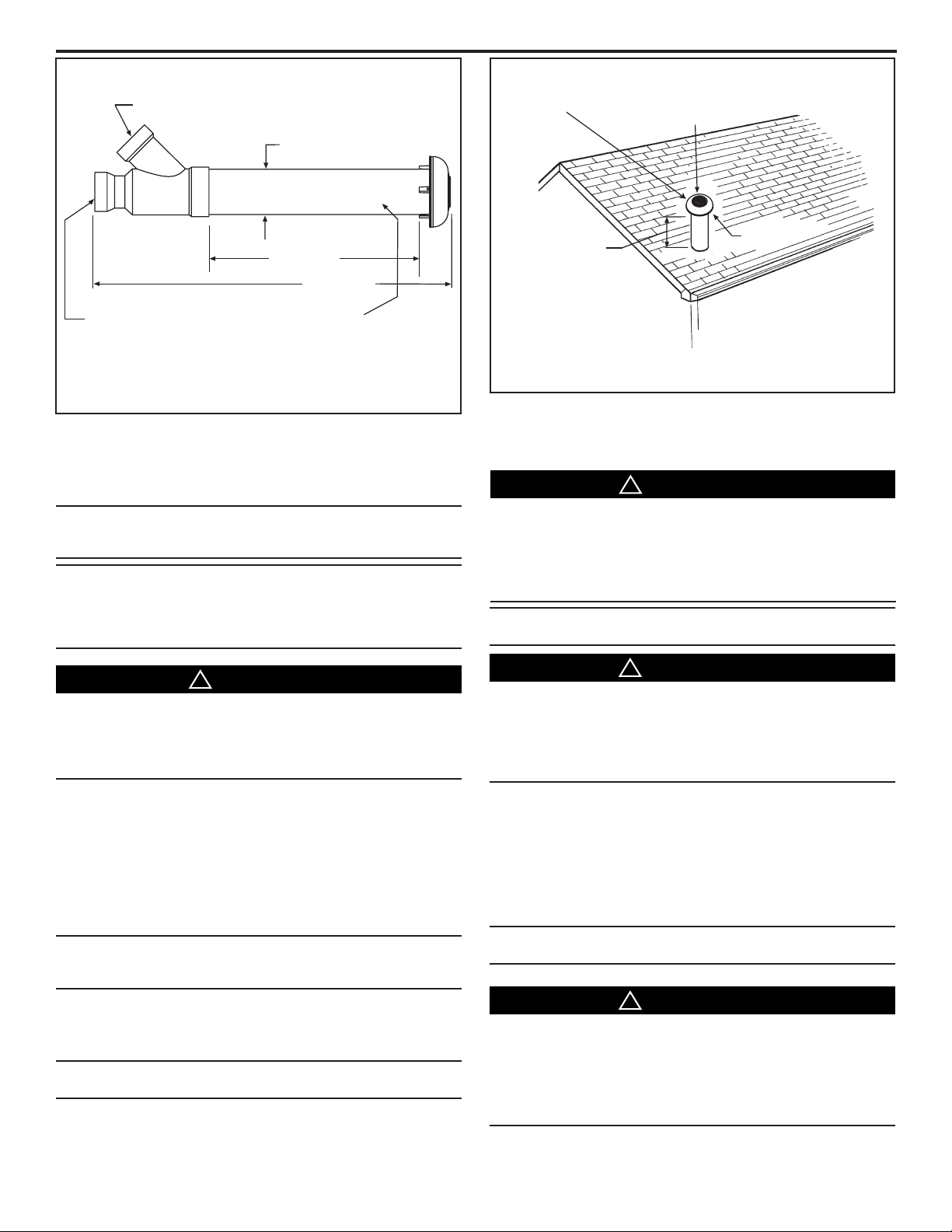
MAINTAIN 12 IN.
MINIMUM CLEARANCE
ABOVE HIGHEST
ANTICIPATED SNOW
LEVEL. MAXIMUM OF
24 IN. ABOVE ROOF.
VENT
COMBUSTION
AIR
REMOVE RIBS
FROM CAP
4.5" DIA
35.2" (typ.)
3" DIA PVC
VENT/EXHAUST
3" DIA PVC INTAKE/
COMBUSTION AIR
MAY BE
LENGTHENED TO 60" MAXIMUM
WITH FIELD REPLACEMENT PIPING.
DO NOT EXTEND MAIN BODY PIPES
WITH PIPE COUPLINGS.
MAIN BODY PIPES
21.125" (typ)
▲
WARNING
!
▲
CAUTION
!
▲
WARNING
!
▲
WARNING
!
2 3
CONCENTRIC VENT KIT ASSEMBLED
INSTALLATION - ROOF TERMINATION (SEE FIG. 3)
1. Determine best location for termination kit.
2. Cut one hole (5 in. diameter) for vent kit.
6. Remove ribs from rain cap. Install the rain cap and the
CONCENTRIC VENT
ROOF TOP APPLICATION
small diameter pipe assembly in the Wye fitting and pipe
assembly. Ensure that the small diameter pipe is cemented
and bottomed into the Wye fitting.
NOTE: Ensure termination height is above the roof surface
or anticipated snow level (1 ft. in USA or 1 1/2 ft. in Canada)
as shown in Figure 4.
NOTE: If assembly is too short to meet the height requirement, the two pipes supplied in the kit may be replaced by
using same diameter, field supplied SDR-26 PVC (ASTM
D2241) pipe. Do not extend the 4" pipe (24" as shipped) to
more than 60 in. (See Figure 2).
DO NOT USE FIELD SUPPLIED COUPLINGS TO EXTEND
MAIN BODY PIPES (4" AND 2-1/2" PIPES). AIRFLOW RESTRICTION WILL OCCUR AND THE FURNACE OR BOILER
PRESSURE SWITCH MAY CAUSE INTERMITTENT OPERATION.
3. Partially assemble the vent kit. Clean the pipe ends and
adjoining sockets with PVC primer (ASTM F-656) and
cement using PVC cement (ASTM D-256).
a. Cement the Wye concentric fitting to larger diameter kit
pipe. (See Figure 1)
b. Cement the rain cap to smaller diameter kit pipe. (See
Figure 1)
NOTE: Instead of cementing the smaller pipe to the rain cap,
RTV silicon sealant may be used to permit future field disassembly for cleaning
4. Install Wye fitting and pipe assembly from the inside through
structure's hole. Install field supplied roof boot/ flashing.
NOTE: Do not allow insulation or other materials to accumulate inside pipe assembly when installing through hole.
5. Secure assembly to roof structure as shown in Figure 4 using
field supplied metal strapping or equivalent support material.
FAILURE TO REMOVE RIBS FROM RAIN CAP FOR VERTICAL VENT KIT INSTALLATIONS MAY CAUSE ICE OR SNOW
TO FORM ON THE RAIN CAP, LEADING TO AN INOPERABLE
FURNACE. FAILURE TO FOLLOW THIS WARNING COULD
RESULT IN PROPERTY DAMAGE, PERSONAL INJURY OR
DEATH.
NOTE: Kit supplied stainless steel screw will be used to secure the rain cap to the pipe.
DRILL A PILOT HOLE IN THE VENT PIPE FOR THE SCREW
SIZE BEING USED. FAILURE TO DRILL ADEQUATE HOLES
MAY CAUSE CRACKING OF THE PVC COMPONENTS, ALLOWING FLUE GASES TO BE RECIRCULATED. FAILURE TO
FOLLOW THIS WARNING COULD RESULT IN PROPERTY
DAMAGE, PERSONAL INJURY OR DEATH.
7. Cement the furnace or boiler combustion air and vent pipes
to the concentric vent termination assembly. See Figure 4
for proper pipe attachment.
8. CHECKOUT: Operate the furnace or boiler to make sure ALL
pipe joints are fastened and sealed to prevent the escape of
combustion products into the building.
NOTE: Two or more installations require a minimum separation distance of approximately one inch between vent kits.
DO NOT OPERATE THE FURNACE OR BOILER WITHOUT
THE RAIN CAP IN PLACE AS RECIRCULATION OF COMBUSTION PRODUCTS MAY OCCUR. WATER MAY ALSO COLLECT
INSIDE THE LARGER COMBUSTION AIR PIPE AND FLOW
TO THE BURNER ENCLOSURE. FAILURE TO FOLLOW THIS
WARNING COULD RESULT IN PRODUCT DAMAGE OR IMPROPER OPERATION, PERSONAL INJURY OR DEATH
Pub. No. 18-CH34D1-7Page 2

INSTALLER'S GUIDE
REMOVE RIBS
FROM CAP
COMBUSTION
AIR
ROOF BOOT
(FIELD SUPPLIED)
COMBUSTION
AIR
VENT
ELBOW
(FIELD SUPPLIED)
MAINTAIN 12 IN.
MINIMUM CLEARANCE
ABOVE HIGHEST
ANTICIPATED SNOW
LEVEL. MAXIMUM OF
24 IN. ABOVE ROOF
SUPPORT
(FIELD SUPPLIED)
VENT
4
CONCENTRIC VENT
ROOF INSTALLATION
INSTALLATION -SIDE WALL VENT (SEE FIGURE 5)
1. Determine the best location for the vent kit.
NOTE: Consider the following when determining the vent kit
location:
A. Vent kit positioned where the vent vapors will not damage
planting/ shrubs or air conditioning equipment or building
structure.
B. Vent kit positioned so it will not be affected by wind eddy
that may allow recirculation of combustion products, or airborne leaves, or light snow.
C. Vent kit positioned where it will not get damaged or be
subjected to foreign objects, such as stones, balls, etc.
D. Vent kit positioned where the vent vapors will not be objectionable.
5
CONCENTRIC VENT
SIDE WALL
NOTE: To prevent the possiblility of condenate freeze-up, do
not install vent kits one above the other.
NOTE: FLUE GAS DEGRADATION
The moisture content of the flue gas may have a detrimental
effect on some building materials. This can be avoided by
using the roof or chimney venting option. When wall venting
is used on any surface that can be affected by this moisture,
it is recommended that a corrosion resistance shield (24
inches square) be used behind the Vent Terminal. This shield
can be made of wood, plastic, sheet metal, etc. Also, silicone
caulk all cracks, seams, and joints within 3 feet of the Vent
Terminal.
2. Cut 1 hole (5 in. diameter) for Vent kit.
3. Partially assemble the vent kit. Clean the pipe ends and
adjoining sockets with PVC primer (ASTM F-656) and
cement using PVC cement (ASTM D-256).
a. Cement the Wye concentric fitting to larger diameter kit
pipe. (See Figure 1)
b. Cement the rain cap to smaller diameter kit pipe. (See
Figure 1)
4. Install Wye concentric fitting and pipe assembly through
structure's hole.
NOTE: Kit supplied stainless steel screw will be used to
secure the rain cap to the pipe.
7. Cement furnace or boiler combustion air and vent pipes to
8. CHECKOUT: Operate the furnace or boiler to make sure ALL
NOTE: Two or more installations require a minimum separation distance of approximately one inch between vent kits.
concentric vent assembly. See Figure 6 for proper pipe attachment.
pipe joints have fastened and sealed to prevent the escape
of combustion products into the building.
6
CONCENTRIC VENT
SIDE WALL INSTALLATION
Pub. No. 18-CH34D1-7 Page 3

INSTALLER'S GUIDE
▲
WARNING
!
▲
CAUTION
!
NOTE: Do not allow insulation or other materials to accumulate inside pipe assembly when installing through hole.
DO NOT USE FIELD SUPPLIED COUPLINGS TO EXTEND
MAIN BODY PIPES (4" AND 2-1/2" PIPES). AIRFLOW RESTRICTION WILL OCCUR AND THE FURNACE OR BOILER
PRESSURE SWITCH MAY CAUSE INTERMITTENT OPERATION.
5. Install rain cap and small diameter pipe assembly in Wye
concentric fitting and large pipe assembly. Ensure small
diameter pipe is bottomed and cemented in Wye concentric
fitting.
DRILL A PILOT HOLE IN THE VENT PIPE FOR THE SCREW
SIZE BEING USED. FAILURE TO DRILL ADEQUATE HOLES
MAY CAUSE CRACKING OF THE PVC COMPONENTS, ALLOWING FLUE GASES TO BE RECIRCULATED. FAILURE TO
FOLLOW THIS WARNING COULD RESULT IN PROPERTY
DAMAGE, PERSONAL INJURY OR DEATH.
6. Secure assembly to structure as shown in Figure 6 using field
supplied metal strapping or equivalent support material.
NOTE: Ensure termination location clearance dimensions
as shown in Figure 5. Do not locate the vent cap directly to
the wall surface. A distance of 1" ± 1/2" is required to prevent
water accumulating between the vent fins.
NOTE: If assembly needs to be extended to allow side wall
thickness requirement, the two pipes supplied in the kit may
be replaced by using same diameter, field supplied SDR-26
PVC (D2241) pipe. Do not extend the 4" pipe (24" as shipped)
to more than 60 in. (See Figure 2). The 4" pipe may be shortened to 14" minimum.
IMPORTANT:
The Commonwealth of Massachusetts requires compliance
with regulation 248 CMR 4.00 and 5.00 for installation of
through – the – wall vented gas appliances as follows:
For all side wall horizontally vented gas fueled equipment
installed in every dwelling, building or structure used in
whole or in part for residential purposes, including those
owned or operated by the Commonwealth and where the side
wall exhaust vent termination is less than seven (7) feet above
finished grade in the area of the venting, including but not
limited to decks and porches, the following requirements shall
be satisfied:
1. INSTALLATION OF CARBON MONOXIDE
DETECTORS. At the time of installation of the side wall
horizontal vented gas fueled equipment, the installing
plumber or gasfitter shall observe that a hard wired carbon
monoxide detector with an alarm and battery back-up is
installed on the floor level where the gas equipment is to
be installed. In addition, the installing plumber or gasfitter
shall observe that a battery operated or hard wired carbon
monoxide detector with an alarm is installed on each
additional level of the dwelling, building or structure served
by the side wall horizontal vented gas fueled equipment. It
shall be the responsibility of the property owner to secure the
services of qualified licensed professionals for the installation
of hard wired carbon monoxide detectors.
a. In the event that the side wall horizontally vented
gas fueled equipment is installed in a crawl space or an
attic, the hard wired carbon monoxide detector with alarm
and battery back-up may be installed on the next adjacent
floor level.
b. In the event that the requirements of this subdivision
can not be met at the time of completion of installation, the
owner shall have a period of thirty (30) days to comply with
the above requirements; provided, however, that during said
thirty (30) day period, a battery operated carbon monoxide
detector with an alarm shall be installed.
2. APPROVED CARBON MONOXIDE DETECTORS. Each
carbon monoxide detector as required in accordance with the
above provisions shall comply with NFPA 720 and be ANSI/UL
2034 listed and IAS certified.
3. SIGNAGE. A metal or plastic identification plate shall
be permanently mounted to the exterior of the building at a
minimum height of eight (8) feet above grade directly in line
with the exhaust vent terminal for the horizontally vented
gas fueled heating appliance or equipment. The sign shall
read, in print size no less than one-half (1/2) inch in size,
“GAS VENT DIRECTLY BELOW. KEEP CLEAR OF ALL
OBSTRUCTIONS”.
4. INSPECTION. The state or local gas inspector of the
side wall horizontally vented gas fueled equipment shall not
approve the installation unless, upon inspection, the inspector
observes carbon monoxide detectors and signage installed
in accordance with the provisions of 248 CMR 5.08(2)(a)1
through 4.
This appliance requires a special venting system. If
BAYAIR30AVENTA or BAYVENT200B are used, a copy of
the installation instructions for the kit shall remain with the
appliance or equipment at the completion of installation. The
venting system installation instructions can be obtained from
the manufacturer by writing to the following address:
Residential Systems
6200 Troup Highway
Tyler, TX 75707
Attention: Manager of Field Operations Excellence
Trane
6200 Troup Highway
Tyler, TX 75707
For more information contact
your local dealer (distributor)
Since the manufacturer has a policy of continuous product and product data improvement, it
reserves the right to change specifications and design without notice.
Pub. No. 18-CH34D1-7Page 4
 Loading...