

Page 1
Installation and Operation
Trane™ Touch-screen Programmable Thermostat
Trane Part Number:
Clarksville Part Number:
Service Part Number:
X13511538-01
BAYSTAT152A
THT02775
SAFETY WARNING
Only qualified personnel should install and service the equipment. The installation, starting up, and servicing
of heating, ventilating, and air-conditioning equipment can be hazardous and requires specific knowledge and
training. Improperly installed, adjusted or altered equipment by an unqualified person could result in death or
serious injury. When working on the equipment, observe all precautions in the literature and on the tags,
stickers, and labels that are attached to the equipment.
July 2011 BAS-SVX44A-EN
Page 2

Copyright
© 2011 Trane. All rights reserved.
This document and the information in it are the property of Trane and may not be used
or reproducedin whole or in part, without the written permission of Trane. Trane reserves
the right to revise this publication at any time and to make changes to its content without
obligation to notify any person of such revision or change.
Trademarks
Trane and its logo are trademarks of Trane in the United States and other countries. All
trademarks referenced in this document are the trademarks of their respective owners.
Warnings, Cautions, and Notices
Warnings, cautions, and notices are provided in appropriate places throughout this
document:
WARNING: Indicates a potentially hazardous situation which, if not avoided,
could result in death or serious injury.
CAUTION: Indicates a potentially hazardous situation which, if not avoided,
could result in minor or moderate injury. It could also be used to alert against
unsafe practices.
NOTICE: Indicates a situation that could result in equipment or property-
damage-only accidents.
2 BAS-SVX44A-EN
Page 3

Table of Contents
Overview .............................................................. 5
Packaged Contents and Tools ............................................ 5
Packaged Contents ................................................. 5
Tools .............................................................5
Specifications and Dimensions .......................................... 6
Product Features and Functions .......................................... 7
Features .......................................................... 7
Functions .........................................................7
Pre-Installation ......................................................... 8
Location Considerations ............................................8
Height Requirements ............................................... 8
Mounting Surfaces ................................................. 8
Maximum Wire Length ............................................. 9
Installation and Wiring .................................................10
Mounting the Thermostat and Cover Removal ........................ 10
Wiring and Wiring Diagrams ....................................... 12
Thermostat Cover Replacement .....................................18
Mounting the Backplate ....................................... 10
Wiring ...................................................... 12
Terminal Identification ........................................13
Wiring Diagrams .............................................13
Power, System Tests, and Software Reset ............................... 19
Applying Power ................................................... 19
Power-up Test .................................................... 19
System Tests ..................................................... 20
Software Reset ................................................... 22
Configuration Option Setup ............................................ 23
Installation Options ............................................... 24
Operation .............................................................27
Thermostat Icon Descriptions .......................................27
Functions .............................................................28
Time Setup ...................................................... 28
Dehumidify Setup ................................................ 28
System Mode Setup .............................................. 29
Fan Mode ....................................................... 29
BAS-SVX44A-EN 3
Page 4

Temporary Override (TOV) Setup ...................................30
General Notes: ............................................... 30
Schedule Setup ................................................... 31
Schedule Display Mode .......................................31
Day/Period/Time Schedule Change Mode ........................ 32
Setpoint/Fan Schedule Change Mode ........................... 33
General Notes for All Schedule Modes ........................... 34
Other Thermostat Functions ............................................ 36
Heat/Cool Indicator Display ......................................... 36
Non-programmable Mode ......................................... 37
Filter Change ..................................................... 38
Clean Screen ..................................................... 38
Local/Remote/Outdoor Temperature Display and Control ..............39
Local/Remote Humidity Display and Control .......................... 40
System Lockout ................................................... 41
To lock the thermostat: ........................................ 41
To unlock the thermostat: ...................................... 41
Temperature Cycle Control ............................................. 42
Other Functional Components .......................................... 44
Sleep Mode ...................................................... 44
Changeover Operation ............................................. 44
Changeover Valve Control ......................................... 44
Extension of Fan-on Time .......................................... 45
Economizer/Time of Day (TOD) .....................................45
Configuration, Time, and Programming Retention ..................... 45
Heat/Cool Relay Confirmation ...................................... 45
Deadband ........................................................ 45
Temperature Display Offset ........................................ 46
Humidity Display Offset ............................................ 46
LCD Backlight .................................................... 46
Compressor Protection ............................................ 46
Permanent Memory Data .......................................... 46
Compressor and Auxiliary Heat Lockout ............................. 47
Error Codes and Exceptions ............................................ 48
Error Codes ......................................................48
Exceptions ....................................................... 49
Troubleshooting ....................................................... 50
4 BAS-SVX44A-EN
Page 5

Overview
The Trane™ Touch-screen Programmable Thermostat is for use with conventional Rooftop Units
(RTU) air conditioners and heat pumps. These units are compact, easy to install, configure, and
operate.
This installation and operation manual provides information about the following:
• Specifications and dimensions
• Product features and functions
• Pre-installation requirements
• Installation and wiring
• Power, system tests, and software reset
• Configuration option setup
• Other thermostat functions
• Temperature cycle control
• Other functional components
• Error codes and exceptions
• Troubleshooting
Note: Before beginning installation, visually inspect all parts for obvious defects for damage. All
components are thoroughly inspected before leaving the factory. Any claims for damage
incurred in shipping should be filed immediately with the carrier.
Packaged Contents and Tools
Packaged Contents
Each programmable thermostat ships with the following:
• One (1) Trane Touch-screen Programmable Thermostat
• One (1) Installation/Configuration Instructions (X39641190-01)
• One (1) Setup/Programming Instructions (X39641189-01)
• One (1) bag of:
- Two (2) machine screws
- Two (2) wood screws
- One (1) security screw
- Two (2) wall anchors
- Two (2) terminal blocks; an 8-pin and a 6-pin
Tools
• One (1) 1/8 inch, flat-bladed service screwdriver
• One (1) small Phillips screwdriver
• Level
• Drill
• Hammer
• Wire cutter/stripper
BAS-SVX44A-EN 5
Page 6
Specifications and Dimensions
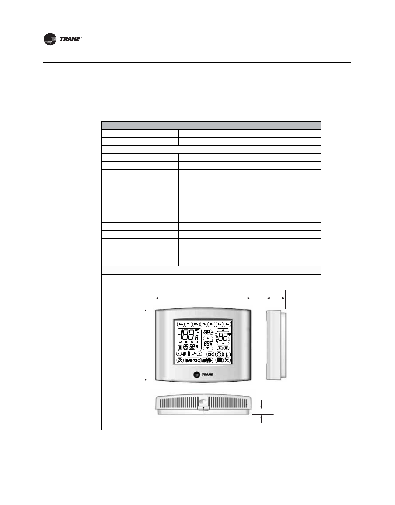
Specifications and Dimensions
The following table and illustration provides the thermostat specifications and dimensions.
Table 1. Specifications and dimensions
Storage
Temperature: –4°F to 158°F (–20°C to 70°C)
Relative Humidity: Between 5% and 95% (noncondensing)
Operating
Temperature: 32°F to 122°F (0°C to 50°C)
Humidity: Between 5% and 95% (noncondensing)
Input Power:
Power Consumption: <2 Watts @24 Vac RMS nominal
Wire Size: 18 to 22 AWG
Output Terminal Rating: 1A @ 30 Vac
Temperature Accuracy: ±1.4°F (0.8°C) from 50°F to 90°F (10°C to 32.2°C)
Temperature Resolution: Configurable @1°F, 0.5°F, 1°C, 0.5C, 0.1°C
Humidity Accuracy: ±3% RH from 20% to 80% RH
Humidity Resolution: 1%
Housing Material:
Mounting: 3.24 in (8.26 cm) for two mounting screws (supplied)
Dimensions
24 Vac (minimum 18 Vac/maximum 32 Vac), 50Hz to 60Hz
Note: Frequency is selected using Configuration Option #0190.
• Polycarbonate/ABS Blend
• UV protected
• U.L. 94-5VA flammability rating
4.65 in
(118 mm)
5.90 in
(150 mm)
1.30 in
(33 mm)
0.3 in
(8 mm)
6 BAS-SVX44A-EN
Page 7

Product Features and Functions
The following is a list of features and functions of the programmable thermostat.
Features
Liquid Crystal Display (LCD) Touch Screen: with symbols for temperature, setpoints, and system
operating modes. In addition, the thermostat has settings for the day of the week, time of day, and
occupancy.
• System Modes:
- Heat
- Cool
- Auto
- Off
- Emergency heat
• Fan Modes:
- On
- Auto
• System Configurations:
- 1 heat/1 cool conventional
- 1 heat/1 cool heat pump
- 1 heat conventional (with and without fan)
- 1 cool conventional
- 2 heat/1 cool heat pump
- 2 heat/2 cool conventional
- 2 heat/1 cool conventional
- 1 heat/2 cool conventional
- 2 heat/2 cool heat pump
- 3 heat/2 cool heat pump
• Time and Dehumidify Settings
• Temporary Override (TOV)
• Scheduling:
- All days: (Mo, Tu, We, Th, Fr, Sa, Su)
- Five (5) days, plus one day, plus one day: (Mo, Tu, We, Th, Fr), (Sa),(Su)
- Five (5) days, plus two days,: (Mo, Tu, We, Th, Fr,) (Sa, Su)
- Seven (7) individual days [default]: (Mo) (Tu) (We) (Th) (Fr) (Sa) (Su)
• Temperature Cycling Control (Patent Pending):
- Integrated adjustable deadband staging
- Configurable cycles per hour (CPH) heat/cool cycles
Functions
The touch-screen programmable thermostat provides additional functions that provide more
flexibility and control. Refer to the sections, “Other Thermostat Functions,” p. 36 and “Other
Functional Components,” p. 44.
BAS-SVX44A-EN 7
Page 8

Pre-Installation
Pre-Installation
This section provides the following pre-installation information:
• Location considerations
• Height requirements
• Mounting surfaces
• Maximum wire length
Location Considerations
When selecting a location, avoid the following areas when installing the thermostat:
• Direct sunlight
• Direct airstream of air diffusers
• Exterior walls and other walls that have a temperature differential between the two sides
• Close proximity to heat sources such as sunlight, appliances, concealed pipes, chimneys, or
other heat-generating equipment
• Drafty regions
• Dead spots behind doors, projection screens, or corners
• Walls subject to high vibration
• High humidity regions
• High traffic areas (to reduce accidental damage or tampering)
Height Requirements
It is recommended to mount the thermostat a maximum distance of 54 inches (137 cm) above the
floor. If a parallel approach by a person in a wheelchair is required, reduce the maximum height
to 48 inches.
Note: For further details regarding wheelchair requirements, refer to ADA Standards for
Accessible Design/4.27 Controls and Operating Mechanisms/4.27.3 Height online at
www.ADA.gov and to local building codes.
Mounting Surfaces
The thermostat can be mounted to any sturdy, vertical surface. Plastic-threaded anchors and M3.5
x 20 mm screws are provided for mounting to plaster or wallboard; 6-32 x 3/4 inch machine screws
are provided for mounting directly to a standard electrical device box. For other surface types, the
user must provide fasteners that are appropriate for the surface.
8 BAS-SVX44A-EN
Page 9
Maximum Wire Length
The thermostat may not function properly if the total resistance of any of the thermostat wires
exceeds 2.5 ohms (refer to Table 2).
Important: Ensure
lengths shown in Table 2 . Best
Table 2. Maximum wire lengths
Maximum Recommended Wire
Copper Wire size
18 AWG (0.75 mm2) 385 ft (117 m) 2,500 ft (762 m) 385 ft (117 m)
2
20 AWG (0.50 mm
22 AWG (0.33 mm
(a) Temperature and humidity readings can be adjusted in the configuration setup for longer wire runs.
) 240 ft (73 m) 1,500 ft (457 m) 240 ft (73 m)
2
) 150 ft (46 m) 1,000 ft (305 m) 150 ft (46 m)
Length From Thermostat to HVAC
Equipment
that the wires from the thermostat to the HVAC equipment do not exceed
practice: use shorter wire lengths.
Remote
Temperature Sensor
to Thermostat
(a)
(Max
)
Remote Humidity Sensor to
Thermostat (Max
Pre-Installation
(a)
)
BAS-SVX44A-EN 9
Page 10

Installation and Wiring
This section provides information about the following:
• Mounting the thermostat and cover removal
• Wiring and wiring diagrams
• Thermostat cover replacement
Mounting the Thermostat and Cover Removal
Before beginning installation, it is recommended to re-read the section, “Pre-Installation,” p. 8 and
then ensure that the following conditions are met:
• A wire access hole is available at the thermostat location
• The wires are accessible through the hole
• The wires are attached to the appropriate terminals on the HVAC equipment
• There is continuity (and not more than 2.5 ohms resistance) between the thermostat location
and the HVAC equipment
• The wires are accurately labeled or color coded
Mounting the Backplate
WARNING
Hazardous voltage!
Disconnect all electric power, including remote disconnects before servicing. Follow proper
lockout/tagout procedures to ensure the power cannot be inadvertently energized. Failure to
disconnect power before servicing could result in death or serious injury.
NOTICE
Equipment damage!
Applying excessive voltage to the thermostat can permanently damage it.
To mount the backplate:
1. Shut off the power to all HVAC equipment. If the security screw was previously installed,
remove it (refer to
Figure 1, p. 11).
10 BAS-SVX44A-EN
Page 11
Installation and Wiring
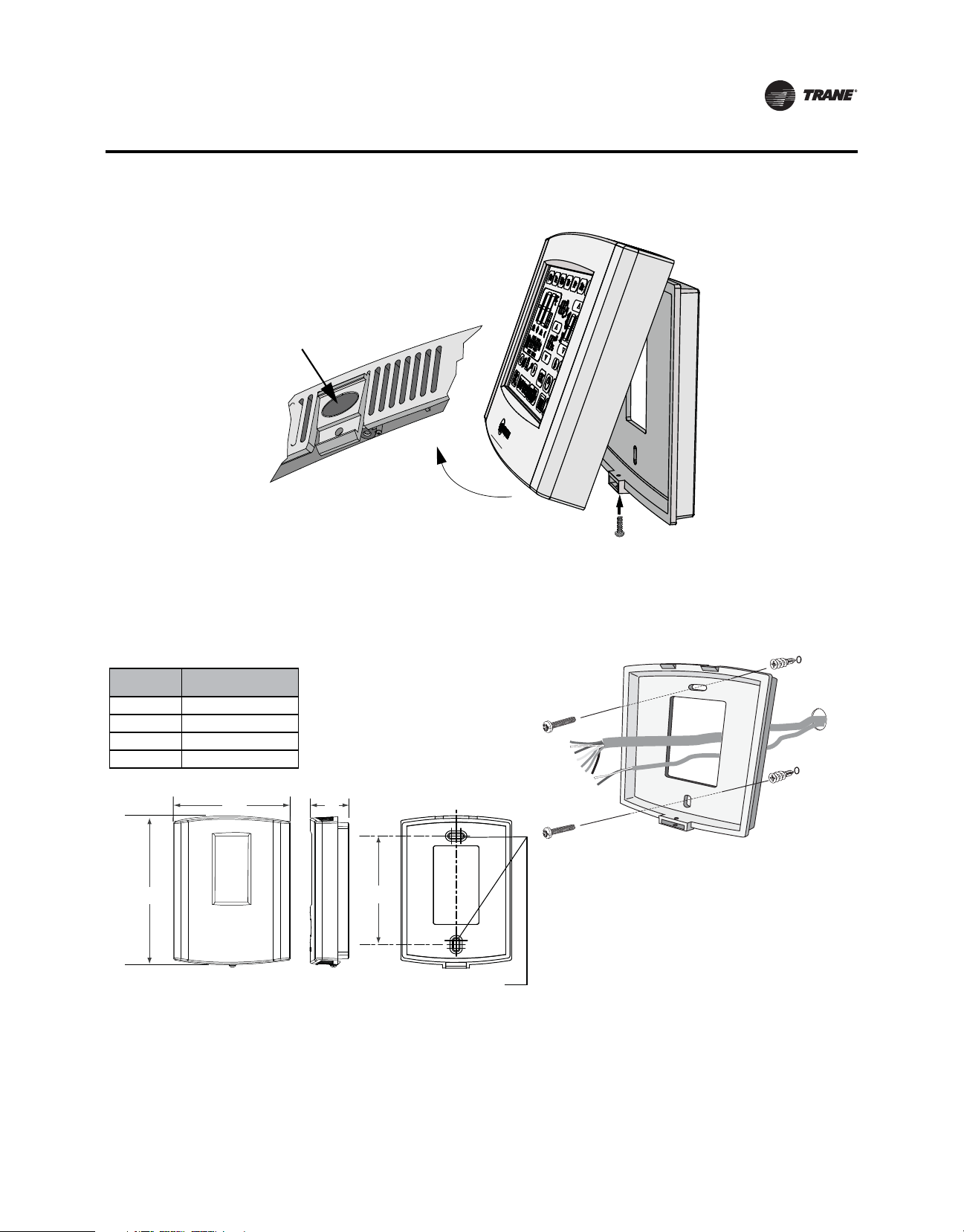
Figure 1. Security screw removal and cover release
Cover thumb tab
NOTE: If the
security screw is
installed, remove
it before
attempting to
Security Screw
2. Push the cover thumb tab to release the cover from the backplate as shown above.
3. Route the wires through the opening in the backplate as shown below. Wires should be marked
ensure proper connection to terminals.
to
remove the cover.
Figure 2. Wire routing, mounting, and mounting dimensions
Dimension
H 3.3 in. (85 mm)
W 5.9 in. (150 mm)
D 1.3 in. (33 mm)
M 3.3 in. (85 mm)
H
Programmable
Touch-screen
W
D
M
Two (2) slots for standard #8-32 (M4),
2”x4” junction box mounting screws.
4. If mounting the backplate directly to a wall surface, hold the backplate against the surface and
then
level and mark the fastener locations.
5. Secure the backplate using appropriate fasteners (refer to the section, “Mounting Surfaces,”
p. 8.) The thermostat must be level and plumb to ensure proper air movement through the
thermostat enclosure.
BAS-SVX44A-EN 11
Page 12

Installation and Wiring
Wiring and Wiring Diagrams
Wiring
WARNING
Hazardous voltage!
Disconnect all electric power, including remote disconnects before servicing. Follow proper
lockout/tagout procedures to ensure the power cannot be inadvertently energized. Failure to
disconnect power before servicing could result in death or serious injury.
NOTICE
Equipment damage!
Applying excessive voltage to the thermostat can permanently damage it.
Note: Terminal
blocks are included with the mounting hardware contained in a small plastic bag
(new installation) or remove terminal blocks from pin header (existing installation).
To wire the thermostat:
1. Connect the wires to the terminal block(s) by:
a. Removing approximately 1/4 inch (6 mm) of insulation from the wires.
b. Using the terminal block screws to securely fasten each wire into the terminal block.
Note: Refer
to Table 3, p. 13 and the wiring diagrams on page 14- through 18 to
determine the correct terminal for each wire.
In some cases the terminal labels (such as Y, G, or R) correctly correspond to the
first
letter of the color wire in which they are connected. However, it is important to
verify which equipment terminals are connected at the other ends of the wires
before connecting the wires to the thermostat.
2. Align the pins/label on the circuit board with the holes/label on the terminal blocks and gently
push
the wired terminal blocks into place on the circuit board (refer to Figure 3).
Figure 3. Attaching the wired terminal blocks to the pins on the circuit boards
C G Y W Rc R
W2 Y2 A S1 S2 Hp Hs Dh
R
Rc
(O/B)W
Y
G
C
Dh
Hs
Hp
S2
S1
A
Y2
(W1)W2
3. Push the excess wire through the hole in the wall cavity or into the junction box.
Important: Do not coil excess wire between the thermostat and the backplate. Use non-
flammable insulation to prevent air movement between the wall cavity and the
thermostat.
12 BAS-SVX44A-EN
Page 13
Terminal Identification
Table 3 identifies the programmable thermostat terminals.
Table 3. Terminal identification
Installation and Wiring
Wiring Diagrams
Connector
Type
8-pin Connectors
6-pin connectors
(a) Label order above is how they appear on the thermostat terminal block.
(b) Text in parentheses applies to only heat pump systems.
Terminal
(a)
Label
Dh Dehumidify relay
Hs External humidity sensor input
Hp External humidity sensor power
S2 External temperature sensor
S1 External temperature sensor
A Economizer relay
Y2 Stage 2 compressor control relay
(W1)W2 (Aux or Em heat relay)
R
Rc
(O/B)W (Changeover valve)
Y Stage 1 compressor control relay
G Fan relay
C Common
Terminal Description
(b)
24 Vac heating
Important: Terminal shipped with jumper connected. Remove jumper if the 24 Vac
24 Vac cooling
Important: Terminal shipped with jumper connected. Remove jumper if the 24 Vac
power supplies are separate.
power supplies are separate.
(b)
Heat relay
Second stage heat relay
The following diagrams show typical wiring scenarios for the touch-screen programmable
thermostat.
Use Table 4 and the corresponding figure to correctly wire the thermostat.
Table 4. System type options for programmable thermostats
System Type Value for Option 130
1-heat/1-cool, conventional 1 Figure 4
1-heat/1-cool, heat pump without auxiliary heat 2 Figure 5
1-heat only, conventional without fan 3 Figure 6
1-heat only, conventional with fan 4 Figure 7
1-cool, conventional 5 Figure 8
2-heat/1-cool, heat pump with auxiliary heat 6 Figure 9
2-heat/2-cool, conventional 7 Figure 10
2-heat/1-cool, conventional 8 Figure 11
1-heat/2-cool, conventional 9 Figure 12
2-heat/2-cool, heat pump without auxiliary heat 10 Figure 13
3-heat/2-cool, heat pump with auxiliary heat 11 Figure 14
BAS-SVX44A-EN 13
See Diagram
Page 14
Installation and Wiring
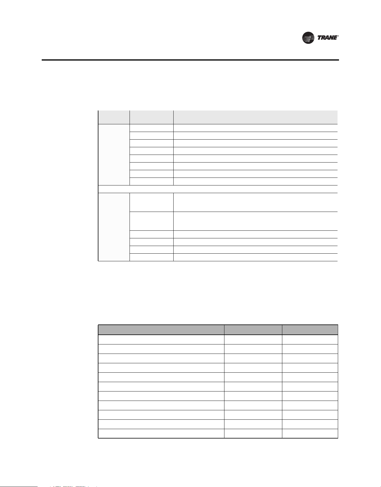
Figure 4. Programmable Thermostat, 1H/1C, Conventional (Option 1)
(jumper
installed)
(jumper
removed)
Dh
Hs
Hp
S2
S1
A
Y2
W2
R
Rc
W
Y
G
C
Dh
Hs
Hp
S2
S1
A
Y2
W2
R
Rc
W
Y
G
C
Remote Humidity Sensor
Remote Temperature Sensor
Compressor
Remote Humidity Sensor
Remote Temperature Sensor
Compressor
Dehumidification
Economizer/TOD
Heat
Fan
Dehumidification
Economizer/TOD
Heat
Fan
Single Transformer:
24 Vac
Two Transformers:
Heating Transformer
24 Vac
Cooling Transformer
24 Vac
L1 (hot)
L2
L1 (hot)
L2
L1 (hot)
L2
Figure 5. Programmable Thermostat, 1H/1C, Heat Pump Without Auxiliary Heat (Option 2)
Dehumidification
Economizer/TOD
Changeover Valve
Fan
24 Vac
L1 (hot)
L2
(jumper
installed)
O/B
Dh
Hs
Hp
S2
S1
A
Y2
W1
R
Rc
Y
G
C
Remote Humidity Sensor
Remote Temperature Sensor
Compressor
14 BAS-SVX44A-EN
Page 15
Installation and Wiring
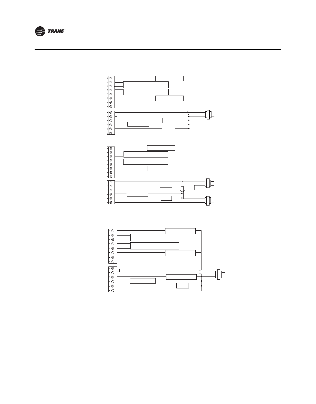
Figure 6. Programmable Thermostat, 1H Only, Conventional Without Fan (Option 3)
(jumper
installed)
Dh
Hs
Hp
S2
S1
A
Y2
W2
R
Rc
W
Y
G
C
Remote Humidity Sensor
Remote Temperature Sensor
Dehumidification
Economizer/TOD
Heat
24 Vac
L1 (hot)
L2
Figure 7. Programmable Thermostat, 1H, Conventional With Fan (Option 4)
(jumper
installed)
Dh
Hs
Hp
S2
S1
A
Y2
W2
R
Rc
W
Y
G
C
Remote Humidity Sensor
Remote Temperature Sensor
Dehumidification
Economizer/TOD
Heat
Fan
24 Vac
L1 (hot)
L2
Figure 8. Programmable Thermostat, 1C, Conventional (Option 5)
(jumper
installed)
Dh
Hs
Hp
S2
S1
A
Y2
W2
R
Rc
W
Y
G
C
Remote Humidity Sensor
Remote Temperature Sensor
Compressor
Dehumidification
Economizer/TOD
24 Vac
Fan
L1 (hot)
L2
BAS-SVX44A-EN 15
Page 16
Installation and Wiring
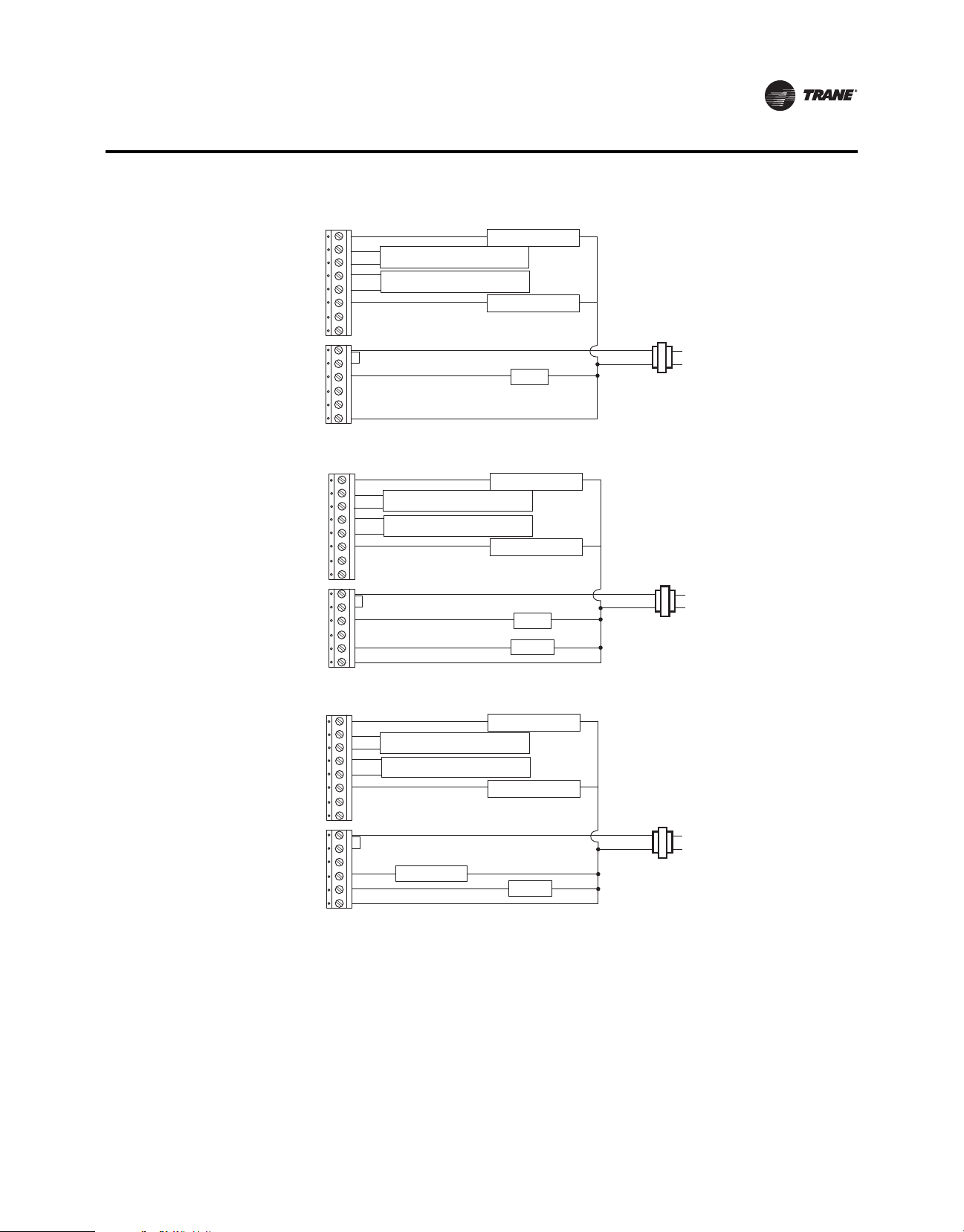
Figure 9. Programmable Thermostat, 2H/1C, Heat Pump With Auxiliary Heat (Option 6)
Dehumidification
Economizer/TOD
Changeover Valve
Fan
24 Vac
(jumper
installed)
O/B
Dh
Hs
Hp
S2
S1
A
Y2
W1
R
Rc
Y
G
C
Remote Humidity Sensor
Remote Temperature Sensor
Auxiliary Heat
Compressor
Figure 10. Programmable Thermostat, 2H/2C, Conventional (Option 7)
(jumper
installed)
Dh
Hs
Hp
S2
S1
A
Y2
W2
R
Rc
W
Y
G
C
Remote Humidity Sensor
Remote Temperature Sensor
Compressor 2
Compressor 1
Dehumidification
Economizer/TOD
Heat 2
Heat 1
Fan
Single Transformer:
24 Vac
L1 (hot)
L1 (hot)
L2
L2
(jumper
removed)
Dh
Hs
Hp
S2
S1
A
Y2
W2
R
Rc
W
Y
G
C
Remote Humidity Sensor
Remote Temperature Sensor
Compressor 2
Compressor 1
Dehumidification
Economizer/TOD
Heat 2
Heat 1
Fan
Two Transformers:
Heating Transformer
24 Vac
Cooling Transformer
24 Vac
L1 (hot)
L2
L1 (hot)
L2
16 BAS-SVX44A-EN
Page 17

Installation and Wiring
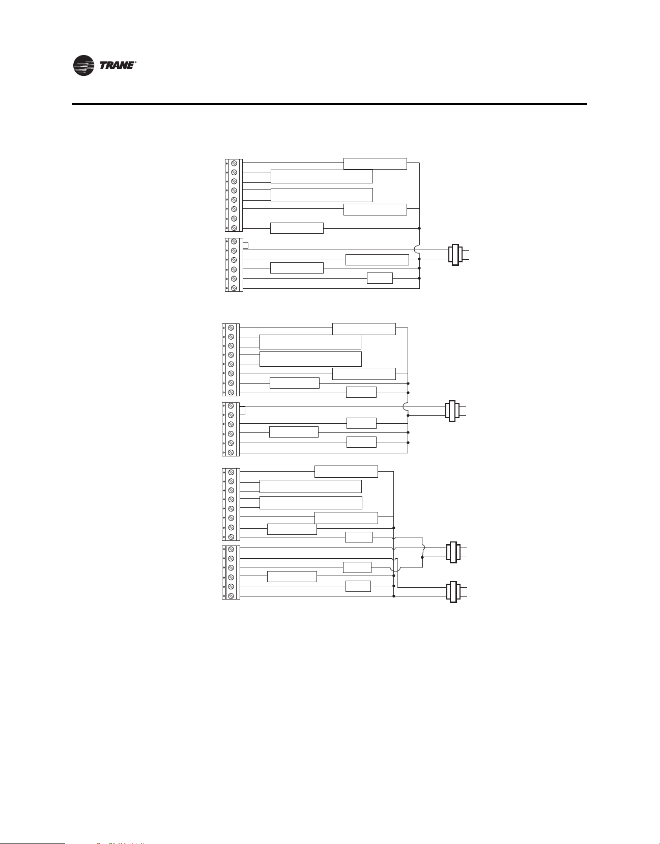
Figure 11. Programmable Thermostat, 2H/1C, Conventional (Option 8)
(jumper
installed)
(jumper
removed)
Dh
Hs
Hp
S2
S1
A
Y2
W2
R
Rc
W
Y
G
C
Dh
Hs
Hp
S2
S1
A
Y2
W2
R
Rc
W
Y
G
C
Remote Humidity Sensor
Remote Temperature Sensor
Compressor
Remote Humidity Sensor
Remote Temperature Sensor
Compressor
Dehumidification
Economizer/TOD
Heat 2
Heat 1
Fan
Dehumidification
Economizer/TOD
Heat 2
Heat 1
Fan
Single Transformer:
24 Vac
Two Transformers:
Heating Transformer
24 Vac
Cooling Transformer
24 Vac
Figure 12. Programmable Thermostat, 1H/2C, Conventional (Option 9)
L1 (hot)
L2
L1 (hot)
L2
L1 (hot)
L2
(jumper
installed)
(jumper
removed)
Dh
Hs
Hp
S2
S1
A
Y2
W2
R
Rc
W
Y
G
C
Dh
Hs
Hp
S2
S1
A
Y2
W2
R
Rc
W
Y
G
C
Remote Humidity Sensor
Remote Temperature Sensor
Compressor 2
Compressor 1
Remote Humidity Sensor
Remote Temperature Sensor
Compressor 2
Compressor 1
Dehumidification
Economizer/TOD
Heat 1
Fan
Dehumidification
Economizer/TOD
Heat
Fan
Single Transformer:
24 Vac
Two Transformers:
Heating Transformer
24 Vac
Cooling Transformer
24 Vac
L1 (hot)
L2
L1 (hot)
L2
L1 (hot)
L2
BAS-SVX44A-EN 17
Page 18

Installation and Wiring
Figure 13. Programmable Thermostat, 2H/2C, Heat Pump Without Auxiliary Heat (Option 10)
Dehumidification
Economizer/TOD
Changeover Valve
Fan
24 Vac
L1 (hot)
L2
(jumper
installed)
Dh
Hs
Hp
S2
S1
A
Y2
W1
R
Rc
O/B
Y
G
C
Remote Humidity Sensor
Remote Temperature Sensor
Compressor 2
Compressor 1
Figure 14. Programmable Thermostat, 3H/2C, Heat Pump With Auxiliary Heat (Option 11)
Dehumidification
Economizer/TOD
Changeover Valve
Fan
24 Vac
L1 (hot)
L2
(jumper
installed)
Dh
Hs
Hp
S2
S1
A
Y2
W1
R
Rc
O/B
Y
G
C
Remote Humidity Sensor
Remote Temperature Sensor
Compressor 2
Auxiliary Heat
Compressor 1
Thermostat Cover Replacement
After completing all wiring, replace the thermostat cover. To replace the cover:
1. Hook the cover over the top of the backplate. Apply light pressure to the bottom of the cover
it snaps into place.
until
2. To help deter tampering, install the security screw into the bottom of the cover as shown below.
Figure 15. Close cover and replace security screw
Install security screw
to deter tampering.
18 BAS-SVX44A-EN
Page 19

Power, System Tests, and Software Reset
This section provides information about:
• Applying power
• Power-up test
• System tests
Applying Power
Restore power to the HVAC equipment. The thermostat initiates a power-up test and will display
an error, if one is detected (refer to the sections, “Power-up Test,” p. 19 and “Error Codes,” p. 48).
If no errors are detected, the home screen appears as shown in Figure 16.
Figure 16. Home screens
Power-up Test
The power-up test is performed any time power is applied to the thermostat. At the start of the
power-up test, the thermostat screen will display the following sequence of events, in order:
• All icons for approximately 1.5 seconds and then;
• The firmware version for 1.5 seconds (in
• Self-testing.
If an error is detected, the error code will display whereby, the user can bypass the error by pressing
the Cancel icon
will display the Home screen.
During the test, the configuration/test icon ( ) blinks on the LCD screen indicating a test is in
progress. Table 5 lists the sequence of tests that occurs:
Note: For a detailed list and descriptions of error codes, refer to the section, “Error Codes,” p. 48.
Example of Home Screen: Heat OnlyExample of Home Screen: Auto Heat/Cool
the clock digit location), and finally;
( ). Once the self-testing has completed checking for any errors, the thermostat
BAS-SVX44A-EN 19
Page 20

Power, System Tests, and Software Reset
Table 5. Error code test sequence
System Tests
Test
Sequence
1 E4;
2 E7;
3 E3;
4 E0;
5
6 E5;
Error Code and Description
• Operating range is 18 to 32 Vrms.
• Low error detection is less than 16.6, ±8.5%.
• High error detection is greater than 34, ±8.5%
• Memory error (write and read 0x55 and 0xAA failed).
• Permanent data error. Access error or checksum error is detected.
• Temperature sensor error. Checks internal and/or external temperature sensor depending on
setting of configuration option 0210.
E1;
• Humidity sensor error. Checks internal or external humidity sensor depending on setting of
configuration option 0200.
• Real Time Clock (RTC) Error.
The system test mode is used to run diagnostics on the thermostat to verify that the unit is
functioning properly.
Referring to Table 6, p. 22, to run a system test:
1. Remove the thermostat cover as shown in the section,“Mounting the Backplate,” p. 10.
2. Press and hold the Configuration button
configuration/test icon ( ) displays and the thermostat is now in Configuration
(refer to Figure 17, p. 21) for 3 seconds. The
Setup
Mode.
3. Press and hold the Configuration button
for 3 seconds again to activate System Test Mode
indicated by the blinking parameter/test icon. When activating system test mode, the first
system test number displayed is always 01.
The test number is changed with the Up ( ) or Down ( )arrows in the center of the display
screen.
Note: The OK button ( ) functions the same as the Up arrow and steps to the next
higher test number.
The test value is changed with the Up ( ) or Down ( ) arrows on the right-hand side of
the display screen.
Note: Changing
a test value will start/stop the test as described in Table 6. Refer to
Figure 17 for arrow locations and Table 6, p. 22 for a list of test values and test
value descriptions.
4. Exit the System
a. Pressing the Configuration button
Test Mode and return to the Home screen by:
momentarily (less than 3 seconds).
b. Touching and holding for 2 seconds.
c. Powering down the thermostat and then powering it up again.
d. Waiting for a 10-minute time out after the last touch.
20 BAS-SVX44A-EN
Page 21

Power, System Tests, and Software Reset
When exiting System Test Mode, the system will run a software reset and return to the
Operating Home screen. If test 15=1, the software reset will be preceded by a Power-up Test
(refer to Table 6, p. 22).
Figure 17. Configuration button and system test mode display
Configuration Button
System
Test
Number
Test icon blinks
Save and move to the next higher or
previous lower System Test Number
System Test Mode Display
Increment or Decrement
the Test Value
Test
Value
Save and move
to next higher
System Test
Number
BAS-SVX44A-EN 21
Page 22

Power, System Tests, and Software Reset
Table 6. System tests and statuses
Test Numbers Test Value/Description
1;
Heat System (W, W2)
2;
Cool System (Y, Y2)
3;
Fan System (G)
4;
Changeover Valve (O/B)
5;
TOD/Economizer System (A)
6;
Dehumidify Relay (Dh)
7;
LCD Full Segment
8;
Touch Keys
9;
Temperature for Outdoor/Remote, S1/S2
Sensor
10;
Temperature for Internal Sensor
11;
Humidity for External Hs/Hp Sensor
12;
Humidity for Internal Sensor
13;
Software Version
14;
Filter
15;
Run Power-up
• 0= Heat stages turn OFF
• 1= Heat stage 1 turns ON and heat stage 2 turns OFF
• 2= Heat stage 2 turns ON and heat stage 1 turns OFF
• 3= Heat stage 1 and 2 turns ON
• 0= Cool stages turn OFF
• 1= Cool stage 1 turns ON and cool stage 2 turns OFF
• 2= Cool stage 2 turns ON and cool stage 1 turns OFF
• 3= Cool stage 1 and 2 turns ON
• 0= Fan turns OFF
• 1= Fan turns ON
• 0= Changeover valve turns OFF
• 1= Changeover valve turns ON
• 0= TOD/Economizer turns OFF
• 1= TOD/Economizer turns ON
• 0= Dh relay turns OFF
• 1= Dh relay turns ON
• 0= No action
• 1= Odd segments turn ON, even segments turn OFF
• 2= Even segments turn ON, odd segments turn OFF
• 3= Full segment turns ON
Note: User will have a 1-second delay to scroll to values 1, 2, and 3. Then, the selected segment test will run for 5
seconds.
• 0= No action
• 1= Test touch keys
Note: Test value 1 will activate all touch areas on the display. The user can turn off each activated touch area, one at
a time, until all are turned off or touch Cancel to exit the test.
• 0= Display current temperature in Fahrenheit
• 1= Display current temperature in Celsius
• 0= Display current temperature in Fahrenheit
• 1= Display current temperature in Celsius
• 0= Display current humidity setpoint
• 1= Display current humidity
• 0= Display current humidity setpoint
• 1= Display current humidity
• 0= No action
• 1= Software revision number
Note: Test value 1 displays the software revision number for 3 seconds and then returns to test mode.
• 0= No action
• 1= Set filter countdown timer to zero (0) to display filter icon after exiting system test mode
• 0= Power-up test OFF (power-up test will not run when exiting test mode)
• 1= Power-up test ON (power-up test will run when exiting test mode)
Note: The value 0 does not affect normal power-up.
Software Reset
A watchdog timer recovers the system in the event of a software or hardware hang up or
malfunction. The thermostat will reboot and run power-up tests if one of the following problems
is detected:
• Exiting System Test Mode (power test only runs if test mode 15 is set to 1).
• The main variables are out of range during run time such as configuration data, active setpoint, RTC data,
fan mode, or operation mode (EEPROM content is restored to default for this error detection).
• When three (3) cycles of power loss is detected and power returns.
• Any recoverable software hang up occurs due to hardware component or software bug.
22 BAS-SVX44A-EN
Page 23

Configuration Option Setup
This section provides information about changing system configurations. For reference, Table 7,
p. 24, lists the Configuration Option Numbers, corresponding values, and descriptions.
NOTICE
Adverse Control System Behavior!
Improper configuration setup could cause unwanted, possibly adverse control system behavior.
Be sure to configure the thermostat according to your system type.
To change the installation configuration:
1. Apply electrical power to the thermostat.
2. Refer to Table 7, p. 24 to determine the correct configuration options. For convenience, either
print out this table or write down the selections and other notes listed.
3. Activate Configuration
WARNING
Live Electrical Components!
The circuit board is energized. Have a qualified licensed electrician or other individual who has
been properly trained in handling live electrical components perform this step. Failure to follow
all electrical safety precautions when exposed to live electrical components could result in death
or serious injury.
a. Removing the thermostat cover as shown in the section,“Mounting the Backplate,” p. 10.
b. Pressing and holding the Configuration button
icon displays solid along with the configuration option number and value (refer to
Figure 18 below).
Option Setup mode by:
for 3 seconds. The configuration wrench
Figure 18. Configuration button and configuration mode display
Save to move to the next
higher or previous lower
Option Number
Option
Configuration
Button
Note: Configuration
Number
mode automatically ends if no buttons are pressed for 10 minutes.
4. Next, press the center or (as shown) to increment or decrement the Option
Note: Changing the Option Number with the up/down arrows will also Save the Option Value. In addition,
the OK will increment the Option Number and Save the Option Value.
Increment or Decrement
the Option Value
Option
Value
Save and move to
next higher
Option Number
or hold for 2
seconds to save
and exit
Configuration
Mode
Number.
5. Press the right side or (as shown) to increment or decrement the Option Value.
6. To Save settings,
• Push the configuration button momentarily as shown in Figure 18
• Touch and hold for 2 seconds
• A 10-minute time out after the last touch in Configuration Mode
exit Configuration Mode and return to the Home screen:
BAS-SVX44A-EN 23
Page 24

24 BAS-SVX44A-EN
Installation Options
Table 7. Installer configuration setup menu
Opt.
Name Def Values/Descriptions Notes
No.
0100
Tem pe ra tu re in di ca tio n/
Resolutio n
0110
Clock Format 12 • 12= 12-hour clock • 24= 24-hour clock
0120
Year 11 • 11–99
0121
Month 1 • 1–12
0122
Day 1 • 1–31
0125
Daylight Savings 2 • 0= Disabled
0126
• Spring Ahead Month
0127
• Spring Ahead Day
0128
•Fall Back Month
0129
•Fall Back Day
0130
System Selection 8 • 1= 1H/1C (Conv) 1st Stage Heat
0140
Schedule Options 1 0=Non-programmable 1= Programmable
0150
TOD/Ec onomizer Output
(Terminal A)
0151
Heat Fan Operation 0 0= System controls fan 1= Thermostat controls fan
0153
Reversing Value O/B 0 0= O/B ON when c all for cool 1= O/B ON when call for heat
0160
Cycles Per Hour (CPH)
[First Stage Compresso r]
0161
CPH (Second Stage
Compressor)
0 • 0= °F, 1 degree resolution
•03
•01
•11
•01
0 • 0= Unused
3 1–5
3 1–5
• 1= °F, 0.5 degree resolution
• 2= °C, 1 degree resolution
• 1= US (1987), changeover at
2:00am
• 2= US (2007), changeover at
2:00am
• 01-12
• 01-31
• 01-12
• 01-31
(W), 1st Stage Comp (Y ), Fan (G)
• 2= 1H/1C (HP) 1st Stage Comp (Y),
Changeover (O/B), Fan (G)
• 3= 1H (Conv) 1st Stage Heat (W),
without fan
• 4= 1H (Conv) 1st Stage Heat (W),
Fan ( G)
• 5= 1C (Conv) 1st Stage Comp (Y),
Fan ( G)
• 6= 2H/1C (HP) 1st Stage Comp (Y),
Changeover (O/B), Auxiliary Heat
(W1), Fan (G)
•1= TOD energizes terminal A during
occupied period, not during
unoccupied period.
• 3= °C with 0.5 degree resolution
• 4= °C with 0.1 degree resolution
• 3= Europe, changeover at 1:00am
• 4= Manual, changeover at 2:00am
• 7= 2H/2C (Conv) 1st & 2nd Stage
Heat (W,W2), 1st & 2nd Stage Comp
(Y,Y2), Fan (G)
• 8= 2H/1C (Conv) 1st & 2nd Stage
Heat (W,W2), 1st Stage Comp (Y),
Fan ( G)
• 9= 1H/2C (Conv) 1st Stage Heat
(W), 1st & 2nd Stage Comp (Y,Y2),
Fan ( G)
• 10= 2H/2C (HP) 1st & 2nd Stage
Comp (Y,Y2), Changeover (O/B), Fan
(G)
• 11= 3H/2C (HP) 1st & 2nd Stage
Comp (Y,Y2), Changeover (O/B),
Auxiliary Heat (W1), Fan (G)
• 2= Economizer energizes terminal A
during a call for cool.
This setting affects indoor temperature display and setpoint display
resolutions. Outdoor temperature display area is always ±1 resolution
for both F and C. Refer to Option 0210.
Available year range: 2011–2099. This value is updated to the real time
clock after setting. Day of the week is updated automatically.
This value is updated to the real time clock after setting. Day of the week
is updated automatically.
Month dependent: this value is updated to the real time clock after
setting. Day of the week is updated automatically.
Options available only if 0125 is set to 4.
TOD is not available in Non-programmable Mode. (Refer to Option 0140)
Only shown for conventional system with heat stages and fan capability.
For heat pump, the fan relay operates with thermostat control.
Only shown for heat pump systems.
Only for systems with cool or HP stage. (Refer to Option 0130.) Selection
in this stage changes 2nd stage cool default CPH.
Only for systems with 2-cool or HP stages. (Refer to Option 0130.)
Configuration Option Setup
Page 25

Table 7. Installer configuration setup menu (continued)
Opt.
Name Def Values/Descriptions Notes
No.
0162
CPH (First Stage
Conventional Heat)
0163
CPH (Second Stage
Conventional Heat)
0164
CPH for Auxiliary Heat 9 1–10
0165
CPH for Emergency Heat 9 1–10
0170
Continuous Backlight 0 0= Backlight ON time is limited 1= Backlight ON continuously
0180
Changeover 1 0= Manual 1= Auto
0181
Deadband 3 • 2= 2°F (1°C)
0182
Minimum Compressor Off
Time
0190
Power Supply Frequency 0 0= 60 Hz 1= 50 Hz
0200
Dehumidify Sensor
Selection
0205
Dehumidification Control 0 0= Active Control 1= Passive Control
0206
Internal Humidity Offset
Adjustment
0207
External Humidity Offset
Adjustment
0210
Temperature Sensor
Selection
0220
Heat Pump Compressor
Lockout Point
0221
Heat Pump Auxiliary
Lockout Point
0230
Temporary Override
Duration Limit
5 1–10
9 1–10
•3= 3°F (1.5°C)
•4= 4°F (2.0°C)
•5= 5°F (2.5°C)
5 • 0= 0 minutes
• 1= 1 minute
• 2= 2 minutes
1 • 0= Humidity display and function is
disabled
•1= Internal humidity sensor
enabled
0 -9% to 9% in 1% increments
0 -9% to 9% in 1% increments
0 • 0= Internal sensor only (10k)
• 1= Internal sensor for H/C control
(outdoor for display only) [10k]
• 2= internal sensor for H/C control
(outdoor for Compr/Aux lockout
control([10k]
0•0= None
• 15= 15°F (–9.5°C)
• 20= 20°F (–6.5°C)
• 25= 25°F (–4.0°C)
0•0= None
• 40= 40°F (4.5 °C)
• 45= 45°F (7.0 °C)
3•0= zero hours
• 1= one hour
• 2= two hours
25
•6= 6°F (3.0°C)
•7= 7°F (3.5°C)
•8= 8°F (4.0°C)
•9= 9°F (4.5°C)
• 3= 3 minutes
• 4= 4 minutes
• 5= 5 minutes
2= External humidity sensor enabled
• 3= Remote indoor sensor for H/C
control (10k)
• 4= Use average temperature =
(local+S1/S2)/2 for H/C control.
• 30= 30°F (–1.0°C)
• 35= 35°F (1.5°C)
• 40= 40°F (4.5°C)
• 45= 45°F (7.0°C)
• 50= 50°F (10.0°C)
• 55= 55°F (13.0°C)
• 60= 60°F (15.5°C)
• 3= three hours
• 4= four hours
Only for conventional systems with heat stages. (Refer to Option 0130.)
Selection in this stage changes default CPH of 2nd stage heat .
Only for conventional systems with two stages of conventional heat.
Only shown for 2H/1C HP or 3H/2C HP systems. (Refer to Option 0130.)
Only shown for 2H/1C HP or 3H/2C HP systems. (Refer to Option 0130.)
Only for systems with both heat and cool stages. (Refer to Option 0130.)
Only applies to auto or manual changeover systems. (Refer to Option
0180.)
Only for systems with cool stage or heat pump. (Refer to Option 0130.)
This setting will extend the compressor OFF time beyond any other
delays incorporated in the Heat/Cool software algorithm.
Power supply input is 24 Vac nominal at either 60 Hz or 50 Hz.
For external humidity control, a 4–20 mA humidity sensor must be
connected to the Hp and Hs terminals to avoid error code E1.
Active control toggles Dh output terminal ON and OFF as specified by
the dehumidify algorithm and is used with a device having its own
dehumidification equipment. Passive control runs cool mode for up to 1
extra minute whenever there is a call for cool and dehumidification.
Allows adjustment of the internal relative humidity reading to account
for accuracy, tolerance, and potential drift. FW should use the adjusted
value for display and humidity control.
Allows adjustment of the external relative humidity reading to account
for accuracy, tolerance, and potential drift. FW should use the adjusted
value for display and humidity control.
Setting 2 applies only to HP systems and is disabled on all conventional
systems.
For setting 1, 2, or 4; if either temperature sensor is out of range, then
the E0 error code will display.
Only for heat pump systems with more heat stages than cool stages and
remote outdoor control sensor. (Refer to Option 0130 and Option 0210.)
Note: A 5°F (2.5°C) deadband between heat pump and auxiliary
lockout will be enforced.
Only for heat pump systems with more heat stages than cool stages and
remote outdoor control sensor. (Refer to Option 0130 and Option 0210.)
Note: A 5°F (2.5°C) deadband between heat pump and compressor
lockout will be enforced.
Used for temporary override (TOV) starting duration time. Setting of
zero does not disable TOV.
Page 26

26 BAS-SV X44A-EN
Table 7. Installer configuration setup menu (continued)
Opt.
Name Def Values/Descriptions Notes
No.
0231
Starting Default Number
of Periods
0232
Starting Default Period
Occ/Unocc Definitions
0233
Days Options for
Scheduling Mode
0240
Heat Temperature Range 90 40–90; 40°F to 90°F 4–32; 4°C to 32°C
0241
Cool Temperature Range 50 50–99; 50°F to 99°F 10–37; 10°C to 37°C
0260
Tem pe ra tu re Di sp la y
Offset
0270
Extended Fan-on Time
Heat
0271
Extended Fan-on Time
Cool
0275
Filter Change Indicator 1 • 0= OFF
0300
Restore Factory Defaults 0 0= No 1= Yes
2 2= two periods 4= four periods
4
If option #0231 is set to 2
Day—Night
•0= UnOcc—UnOcc
•1= UnOcc—Occ
•2= UnOcc—UnOcc
•3= UnOcc—Occ
•4= Occ—UnOcc
•5= Occ—Occ
•6= Occ—UnOcc
•7= Occ—Occ
•8= UnOcc—UnOcc
•9= UnOcc—Occ
• 10= UnOcc—UnOcc
• 11= UnOcc—Occ
• 12= Occ—UnOcc
• 13= Occ—Occ
• 14= Occ—UnOcc
• 15= Occ—Occ
3 • 0= 1 day; Mo-Su all days share the
same schedule
• 1= 5+1+1 days; Mo-Fr share a
schedule. Sa and Su each have an
independent schedule
0 • –3= –3°F (–1.5°C)
• –2= –2°F (–1.0°C)
• –1= –1°F (–0.5°C)
•0= None
0 0= OFF 90= ninety seconds
0 0= OFF 40= forty seconds
• 1= 30 days
• 3= 90 days
If option #0231 is set to 4
Morn—Day—Evening—Night
•0= UnOcc—UnOcc—UnOcc—Unocc
•1= UnOcc—UnOcc—Unocc—Occ
•2= UnOcc—UnOcc—Occ—UnOcc
•3= UnOcc—Unocc—Occ—Occ
•4= UnOcc—Occ—UnOcc—UnOcc
•5= UnOcc—Occ—UnOcc—Occ
•6= UnOcc—Occ—Occ—UnOcc
•7= UnOcc—Occ—Occ—Occ
•8= Occ—UnOcc—UnOcc—UnOcc
•9= Occ—UnOcc—UnOcc—Occ
• 10= Occ—UnOcc—Occ—UnOcc
• 11= Occ—UnOcc—Occ—Occ
• 12= Occ—Occ—UnOcc—UnO cc
• 13= Occ—Occ—UnOcc—Occ
• 14= Occ—Occ—Occ—UnOcc
• 15= Occ—Occ—Occ—Occ
• 2= 5+2 days; Mo-Fr share a
schedule. Sa-Su share a schedule.
• 3= 7 days; Each day has an
independent schedule
•1= 1°F (0.5°C)
•2= 2°F (1.0°C)
•3= 3°F (1.5°C)
• 4= 120 days
• 6= 180 days
• 12= 365 days
Provides starting default number of periods for all days of the week.
Occupancy setting can be changed during scheduling for each period/
day.
Any value toggle of Option 0233 will reset the schedule to the default
values of Options 0231 and 0232, and in addition, return the schedule
to default values.
Only for systems with heat stage. (Refer to Option 0130.)
Only for systems with cool stage. (Refer to Option 0130.)
Only applies to control temperature and display temperature for internal
and indoor remote sensor. Does not apply to outdoor temperature for
display.
This option is not available if Option 0151=0 or if system is cool only.
(Refer to Option 0130.)
This option is not available for systems with heat only. (Refer to Option
0130.)
Filter change disabled in OFF. Timer values start on first power-up or
reset of an active filter change icon.
No= No action; Yes= Resets all parameters to default except calendar/
daylight savings time/system selection.
Configuration Option Setup
Page 27

Operation
If configured properly, the touch-screen programmable thermostat will control HVAC equipment
to maintain room temperature automatically. This section provides general descriptive and
procedural information intended for daily operation.
Thermostat Icon Descriptions
The illustration below provides a description of all icons for the thermostat. Bubbled letters in red
correspond to the letters indicated in each section title.
Note: In
Figure 19. Icon descriptions
normal operations, not all icons are visible.
Mo Tu We Tu Fr
Days of the week
Mo–Fr shown selected
(
Sa and Su shown unselected
A
Setpoint display
from top clockwise:
• Increment • Fahrenheit/Celsius
• Decrement • Override hourglass
• Cool/heat setpoint thermometer
)
• Temperature setpoint
B
From top to bottom:
• Indoor temperature in
Fahrenheit/Celsius
• Schedule periods
(morning/day/
evening/night)
• Occupancy status
• Clock
• AM/PM
• DAYS
• HOURS
From left:
• Left arrow adjustment
• Filter change
• Touch screen lock
• Configuration/test
• Right arrow adjustment
J
C
Heat indicator,
Cool indicator
D
I
F
Screen
cleaning
timer
GH
From left:
• System mode
• Fan mode
Confirm
E
Top clockwise:
• Clock mode
• Setpoint mode
• Cancel
• Schedule
Outdoor temperature/
humidity display
from top to
bottom:
• Outdoor temperature
in Fahrenheit/Celsius
• Increase humidity setpoint
• Humidity display
• Decrease humidity setpoint
BAS-SVX44A-EN 27
Page 28

Functions
There are common functions on the programmable thermostat that require initial setting or
changing. This section describes the following setup modes:
• Time setup, dehumidify setup, and system mode setup
• Fan mode and temporary override (TOV) mode
• Schedule setup
• Table of default settings and worksheet
Note: The
touch screen can be locked out to prevent unauthorized personnel from changing
settings. A lockout will disable changes to System, Fan, Scheduling, Time and TOV. If the lock
icon ( ) is displayed on the LCD screen, the user will need to unlock the touch screen to
allow changes (refer to the section, “System Lockout,” p. 41).
Time Setup
D
E
To set or change the time:
1. From the Home screen,
hours:minutes (with the hours blinking to indicate it is selected) and either AM or PM (AM/PM
is
not shown for 24-hour clock) as shown:
Note: To
2. Touch either or to switch between hours or minutes.
3. Touch or to increment or decrement the hours/minutes. Touch and hold either
button for more than 1 second to fast scroll through values.
4. Touch to save and exit Time
Note: A
5. Touch to exit without saving any changes.
Dehumidify Setup
Note: This function is displayed only for systems configured with dehumidify enabled. (Refer to
To set or change dehumidification:
1. Touch to activate the Dehumidify
humidity setpoint with adjustment arrows.
2. Touch or to increment or decrement the humidity setpoint by 1% increments. Touch
and hold either button for more than 1 second to fast scroll through values.
Note: Dehumidification
3. Touch to save and exit Dehumidify
Note: A
4. Touch to exit without saving any changes.
I
F
Table 7, p. 24).
20-second time out will also save and exit Time Setting Mode.
D
Configuration Option Number 0200).
20-second time out will also save and exit Dehumidify Setting Mode.
J
touch to activate the Time Setting Mode. The LCD screen displays
change clock to either 12-hour or 24-hour readout, refer to Option Number 0110 in
Setting Mode.
E
F
Setting Mode. The LCD screen displays the current
setpoint can be adjusted from 30% to 80%.
Setting Mode.
28 BAS-SVX44A-EN
Page 29

Functions
System Mode Setup
Note: If unable to change the system mode to a desired setting, check the system type setting and
the manual/auto-changeover setting (refer to the section, “Configuration Option Setup,”
p. 23) to verify how the thermostat is configured with heat and cool modes, and that it
permits manually changing them. (Refer to Configuration Option Numbers 0130 and 0180).
Depending upon the model and system type, the thermostat can be set to one of five modes:
Cooling, Heating, Emergency
Note: All
To set the system mode:
1. Touch area to activate the System
are visible with the current system setting blinking. Each touch in the system selection box will
step
to the next available setting as shown below.
Emergency
Heat
2. Choose a system mode and then either touch or a 20-second time out will save the system
mode setting and return to the Home screen.
Note: Touching
E
G
F
Heat, AUTO,orOFF.
system icons may not be available– this is configuration setup dependent.
Cooling Mode; cools the room to bring it down to the cooling setpoint.
Heating Mode; heats the room to bring it up to the heating setpoint.
Emergency Heat Mode; heats the room using the emergency heat mode equipment.
AUTO Mode; switches automatically between heating and cooling modes as required.
OFF Mode; turns OFF both heat and cool modes regardless of the room temperature. OFF
mode also disables the fan relay.
Mode Setup. All system mode settings available
Heat
Cool Auto H/C Off
OFF
another active area on the display screen (such as clean screen, clock,
humidity, or schedule) will also save the system mode setting selected in Step 2 and
activate the newly selected system setting.
Fan Mode
Touching Cancel ( ) will exit system mode setup without saving any changes
E
G
F
.
Note: The fan is only displayed on systems configured with the fan enabled. If disabled, then the
fan icon on the LCD screen is not visible. The Fan mode is typically configured in Schedule
Setup. Fan mode changes from the Home screen initiates an override (TOV) [refer to the
section, “Schedule Setup,” p. 31].
There are two fan modes. Each are indicated by an icon on the display:
Fan AUTO Mode; turns the fan ON and OFF as needed according to equipment configuration.
Fan ON Mode; runs the fan continuously.
To
enter fan mode:
1. Touch area to activate the Fan
Display Mode and the active fan mode will blink.
Note: Touching , , another active area, or a 20-second time out will return to the Home
screen without making changes to the fan.
BAS-SVX44A-EN 29
Page 30

Functions
2. Next, touch in the fan selection box to put the thermostat into TOV Temporary Override
Mode and to step to the next available setting as shown below.
Auto Mode:
Auto Flashes
On Mode:
Arrows Flash
3. Refer to the next section, Temporary
cancel and return to the Home screen.
Temporary Override (TOV) Setup
TOV allows the user to temporarily override the scheduled temperature setpoint and/or fan
settings. There are two ways to enter TOV Mode from the Home screen:
• Quick
• User
In TOV
with the Up, Down, or Fan areas.
• To adjust the TOV time period:
•ToCancel the
TOV: Touch the Occ ( ) or Unocc ( ) icon from the Home screen. A TOV session will
start up using the last occupied schedule setpoint settings, the last occupied fan setting, and the
default
TOV time period (Option Number 0230). Touch OK or wait for a 20-second time out to
put the thermostat into quick TOV Active Mode; OR
Configurable TOV: Touch either the Up or Down arrow to blink the setpoint for 20 seconds.
Touch of the Up or Down arrows within 20 seconds to change the setpoint and put the
thermostat into TOV Setpoint Change Mode; OR
Touch the Fan to blink the present Fan setting for 20 seconds. Touch the Fan area within 20
seconds
to change the Fan setting and put the thermostat into TOV Setpoint Change Mode.
Setpoint Change Mode, further adjustments can be made to the setpoint or Fan mode
Note: For
Auto H/C systems, use the cool mode icon ( ) or the heat mode icon ( ) to toggle
between cool and heat setpoints respectively.
• Touch
the clock icon ( ) to enter TOV Time Setup Mode. The left/right arrow ( or )
will toggle between Days/Hours and the middle Up/Down arrows ( or ) will
increment or decrement the time.
Note: A
second touch of the clock icon ( ) will put the thermostat into Hold Mode
which holds the TOV settings indefinitely until canceled by the user. Additional
touches
of the clock icon ( ) will toggle the thermostat between DAYS/HOURS
and Hold.
• Toggle
back to readjust the setpoint(s) by touching the thermometer icon ( ).
• Touch area to activate the desired settings. Active TOV is indicated by a solid non-blinking
hourglass ( ).
Note: Desired
settings are also activated after a 20-second time out.
TOV time period, touch at any time to cancel and exit TOV Mode.
Override (TOV) Setup to set overrides or touch to
B C E
G
F
General Notes:
• TOV setup has three modes: TOV Setpoint Setup, TOV Time Setup, and TOV Active.
• If Fan is enabled, then TOV Fan setting can be changed in either TOV
Time Setting Mode.
• If a TOV is in active status, then those TOV settings become the starting setpoints if entering into
new User Configurable TOV session.
a
• Fan icons do not display on the LCD screen if the system is not configured for fans.
• The confirm icon is not displayed when the user is in TOV
30 BAS-SVX44A-EN
Setpoint Mode or TOV
Active Mode.
Page 31

• When starting/activating TOV, the displays solid indicating that TOV is ACTIVE.
• Quick
•InQuick
•InUser
• During a power outage, if the unit was in TOV
• TOV is not available in non-programmable mode (refer
Schedule Setup
Schedules can be used to set the day/time/periods and to set the fan and setpoints.This section
describes the following:
• Schedule display mode
• Day/period/time schedule change mode
• Setpoint/fan schedule change mode
When setting either the day/period/time schedule or setpoint schedule, refer to Table
default settings and worksheet.
Functions
TOV Active Mode will show Occ ( ) icon while User Configurable TOV Active Mode
Occ/UnOcc will be blank.
TOV Active Mode, the typical display will show the TOV time remaining as HH:MM
(Hours:Minutes) for 45 seconds. After the 45 seconds, the display will cycle to Time of Day with
AM/PM for 10 seconds, followed by HH:MM for 5 seconds, and continue repeating Time of Day
and HH:MM until time expires or Cancel.
Configurable TOV Active Mode, the typical display will show DD:HH (DD is days and
HH is Hours). After the 45 seconds, the display will cycle to Time of Day with AM/PM for 10
seconds, followed by Days (for 3 seconds) if 1 day or more TOV time left, HH:MM (for 5 seconds),
and continue repeating Time of Day, Days, and HH:MM until time expires or Cancel.
Mode, it will return to the last TOV settings when
power is returned.
to Installation Option Number 0140).
8, p. 35 for
Schedule Display Mode
This display mode is used to view current settings such as setpoints, periods, and day of the week
as shown in the illustration below. When in Schedule Display Mode, the user cannot change
settings.
• From the Home screen,
• Touch any of the iconstoview the day or day group schedule. The day
selected is displayed in an inverse graphics (similar to the Tu weekday
or day group can be selected at one time. Day groups are determined by Installation Option
Number 0233.
• Touch any to view its current schedule. The current period will blink.
• For Auto H/C systems, touch or to toggle between Cool or Heat setpoints. Either icon
will blink depending on which setpoint is being displayed.
• Touch cancel ( ) to exit Schedule
A
C E J
touch to enter Schedule Display mode.
as shown). Only one day
Display mode or after 20-second time out.
BAS-SVX44A-EN 31
Page 32

Functions
• Touch blinking to proceed to the next section, Day/Time/Period Schedule Change
Mode,
before the 20-second time out. Time out changes to 60 seconds for the change modes.
Tu
Top Arrow: Cool
Bottom Arrow: Heat
Day/Period/Time Schedule Change Mode
This mode is used to select the day, day group, multiple day groups, period times, fan, and
occupancy. The default settings, Number of Periods, Occupancy Settings, and Day Groups, are
configured using Configuration Option Numbers 0231, 0232, and 0233 respectively.
To change day/period/time:
1. First day or day group selected is carried over from the schedule display mode. To change/add
multiple
of day groups are toggled ON or OFF with each touch.
Note: The
Note: Day
2. Touch to select the period of day.
3. To change the start time of the selected period, touch either or to increment or
decrement the time in 15-minute increments.
4. Touch to change the occupancy setting to either occupied ( ) or unoccupied ( ), if desired.
5. If Fan is enabled, touch the Fan area to change to desired fan setting.
6. Repeat steps 1 through 5 to set the start times and occupancy for all days/periods.
7. Touch to proceed to the next section, Setpoint/Fan
time out.
Note: Touch and to toggle between Day/Period/Time
Note: Selecting OK will
days or day groups, touch the desired weekday icon (Mo, Tu, We, and so on). The day
first single day or day group selected is the master. Any additional day or day groups
selected are temporarily loaded with the master values. Any changes will apply to all
selected day or day groups.
or Day Groups can only be selected in Day/Period/Time Schedule Change
Mode.
Setpoint/Fan Schedule Mode.
save changes and a Cancel will remove any changes since the last
save and then exit schedule change mode.
A
B E J
Schedule Mode, before the 60-second
Schedule Change Mode and
32 BAS-SVX44A-EN
Page 33

Tu
Top Arrow: Cool
Bottom Arrow: Heat
Functions
The following are the available day group schedules that can be configured
with Installation Option Number 0233:
• All Days [default]:(MoTuWeThFrSaSu)
• Five days, plus one day, plus one day: (Mo Tu We Th Fr) (Sa) (Su)
• Five days, plus two days: (Mo Tu We Th Fr) (Sa Su)
• Seven individual days: (Mo) (Tu) (We) (Th) (Fr) (Sa) (Su)
Setpoint/Fan Schedule Change Mode
This mode is used to set the heat and/or cool setpoint, occupancy, and the fan settings for the
selected day, day group, or multiple day groups. Day or Day Groups cannot be changed in this
mode. Default settings are shown in Table 8, p. 35.
To change the setpoint/fan schedule:
1. From the previous section, touch to select the period of day.
2. To change the setpoint of the selected period, touch either or to increment or
decrement the setpoint temperature.
3. For Auto H/C systems, touch or to toggle between cool setpoint and heat setpoint.
4. Touch area to change the fan mode for the selected period.
5. Touch to change the occupancy setting for the selected period to either occupied ( )or
unoccupied ( ), if desired.
6. Repeat steps 1 through 5 to set all fan, occupancy, and temperature setpoints for each period
desired.
as
7. When all changes are completed, touch to save settings. A second touch of will exit out
of Schedule
save.
Note: Day
Note: Touch and to toggle between Day/Period/Time
Change mode, and return to the Home screen. A 60-second time out will also
or day groups cannot be changed in Setpoint/Fan Schedule Change Mode. The
user must return to Day/Period/Time Schedule Change Mode to select different days
or day groups. Touch and to toggle between Day/Period/Time
Change Mode and Setpoint/Fan
Setpoint/Fan Schedule Mode.
B C E
J
F
Schedule Mode.
Schedule
Schedule Change Mode and
Tu
Top Arrow: Cool
Bottom Arrow: Heat
BAS-SVX44A-EN 33
Page 34

Functions
General Notes for All Schedule Modes
• Touching Cancel ( ) will cause all changes after the last save to be lost, the display will return to
the Home screen, and the system will return to the last save schedule settings.
• When any changes are made to the schedule, the first touch of OK will save changes and return
to the last schedule changes mode. The second touch of OK, if no further changes are made,
will exit Schedule Change Mode and return to the Home screen or TOV, if still active.
• Screens may vary depending on configuration settings.
• Schedule mode is not available in non-programmable mode (Refer
0140).
to Configuration Option Number
34 BAS-SVX44A-EN
Page 35

Table 8. Default settings and worksheet
Symbol Legend Listed Below
4-Period Defaults
2-Period Defaults
Monday
Tuesday
Wednesday
Thursday
Friday
Saturday
Sunday
Functions
6:00 AM 70°F (21.0°C) 78°F (25.5°C) AUTO
8:00 AM 62°F (16.5°C) 85°F (29.5°C) AUTO
6:00 PM 70°F (21.0°C) 78°F (25.5°C) AUTO
10:00 PM 62°F (16.5°C) 82°F (28.0°C) AUTO
8:00 AM 70°F (21.0°C) 78°F (25.5°C) AUTO
10:00 PM 62°F (16.5°C) 82°F (28.0°C) AUTO
:° °
: ° °
:° °
: ° °
:° °
: ° °
:° °
: ° °
:° °
: ° °
:° °
: ° °
:° °
: ° °
:° °
: ° °
:° °
: ° °
:° °
: ° °
:° °
: ° °
:° °
: ° °
:° °
: ° °
:° °
: ° °
AUTO
A
UTO
AUTO
A
UTO
AUTO
A
UTO
AUTO
A
UTO
AUTO
A
UTO
AUTO
A
UTO
AUTO
A
UTO
AUTO
A
UTO
AUTO
A
UTO
AUTO
A
UTO
AUTO
A
UTO
AUTO
A
UTO
AUTO
A
UTO
AUTO
A
UTO
Symbol Legend:
Morning
Day
Evening Night Time
Heat
Cool Fan
ON
BAS-SVX44A-EN 35
Page 36

Other Thermostat Functions
The programmable thermostat has other functional features which provide more flexibility and
control in its operation. Those features are:
• Heat/Cool indicator display (for both programmable and non-programmable thermostats (refer
the next section, “Heat/Cool Indicator Display” )
to
• Non-programmable mode
• Filter change
• Clean screen
• Local/remote/outdoor temperature display and control
• Local/remote humidity display and control
• System lock
Heat/Cool Indicator Display
Setpoint display: when the system is set for only Heat or only Cool, there is no flame ( ) or
snowflake ( ) icon under the setpoint value.
When the system is set to AUTO ( ), the following applies:
• When the thermistor used for H/C control is above the Cool Setpoint, the Cool Setpoint will
on the display along with the snowflake ( ) under the setpoint.
show
• When the thermistor used for H/C control is below the Heat Setpoint, the Heat Setpoint will
on the display along with the flame ( ) under the setpoint.
show
• When the thermistor used for H/C control is between the Cool and Heat Setpoints (inclusive),
last active system setpoint (Cool or Heat) will show on the display.
the
When the system is set to AUTO (
under the setpoint are as follows:
• When no Cool or Heat cycle is running and no compressor protection timer running, if the Heat
Setpoint
1.75 seconds OFF.
• When no Cool or Heat cycle is running and no compressor protection timer running, if the Cool
Setpoint
and 1.75 seconds OFF.
• When Cool cycle is running, then the snowflake ( ) under setpoint should be solid.
• When Heat cycle is running, then the flame ( ) under setpoint should be solid.
• When the compressor timer is running before Cool cycle, then the snowflake ( ) under
setpoint should blink 1.5 seconds ON and
• When the compressor timer is running before Heat cycle, then the flame ( ) under setpoint
should blink 1.5 seconds ON and
is showing, then the flame ( ) under the setpoint will blink at 4.5 seconds ON and
is showing, then the snowflake ( ) under the setpoint will blink at 4.5 seconds ON
), the blink rates for the snowflake ( ) and flame ( )
0.5 second OFF.
0.5 second OFF.
36 BAS-SVX44A-EN
Page 37

Non-programmable Mode
The thermostat is capable of being configured as non-programmable (refer to Configuration
Option Number 0140 in Table 7, p. 24). If the thermostat is set to non-programmable mode, certain
icons are not displayed and scheduling and override functionality is not available. The Home
screens will similarly display as shown below.
Other Thermostat Functions
Example of Non-programmable Mode Home Screen:
Auto Heat/Cool With Cool Setpoint
Example of Non-programmable
Mode Home Screen: Heat Only
Non-programmable Functionality
• Scheduling and Override modes are not available.
• The following features are not displayed; occupied ( ), unoccupied ( ), period schedules
(
• Fan can be set to either AUTO or ON.
• Setpoints are changed directly by touching the setpoint Up/Down arrows. If the system is set
to AUTO,
( ) and the flame icon ( ).
• All other Non-programmable
such as System Mode Setup, Fan Mode, Humidity Setup, or Clock.
then the user can toggle between Cool and Heat setpoints with the snowflake icon
).
Mode functionality is the same as in Programmable Mode,
BAS-SVX44A-EN 37
Page 38

Other Thermostat Functions
Filter Change
Filter change indicates when the system change filter timer is expired. The filter icon ( ) will blink
continuously 1.5 seconds ON and 0.5 seconds OFF on the Home screen (or TOV Active screen)
until this feature is reset. To reset the filter change indicator, press and hold both left and right
arrows at the same time for 3 seconds (refer to the illustration below).
The default setting for filter replacement is one (1) month. To change this duration, refer to
Configuration Option Number 0275 in Table 7, p. 24.
Reset Arrows and
Filter Change Icon
Clean Screen
Clean
Screen
Icon
The Clean Screen feature allows the user to clean the LCD screen by deactivating the touch screen
without affecting any current settings. From the Home screen, touch the clean screen icon ( ).
The LCD screen becomes inactive and only shows a 30-second countdown (shown below on the
right) before returning to the Home or TOV Active screen. Clean the screen with a non-abrasive
cloth and a mild ammonia-free cleaning solution.
30-second
Countdown
38 BAS-SVX44A-EN
Page 39

Other Thermostat Functions
Local/Remote/Outdoor Temperature Display and Control
The thermostat has the capability of displaying the local indoor temperature and/or the remote
indoor/outdoor temperatures, depending on the value setting for Configuration Option Number
0210. There are two terminals to connect the remote sensor, S1 and S2. The table that follows
provides information about displaying either local, remote, or outdoor temperatures and how
temperatures are controlled (refer to Configuration Option Number 0210 in Table 7, p. 24).
Indoor Temperature
Outdoor/Remote
Temperature
Option
Number 0210
0
1
2
3
4
(a) Remote sensor can be placed indoor or outdoor depending on the application.
(b) If an out-of-range error occurs on either the local or remote thermistor (but not both), then the firmware will use the
good thermistor reading without averaging to control Cool or Heat cycles. If or when the bad thermistor returns to a good
state, then the firmware will return to using both thermistors and average the two values.
Installer Parameter Number Value Description
Uses the internal/local sensor for Cool and Heat control. Displays only local indoor temperature.
Uses the internal/local sensor for Cool and Heat control. Displays both indoor local and remote
temperatures. Remote sensor typically placed outdoors.
Uses internal/local sensor for Cool and Heat control. Uses remote S1/S2 thermistor for compressor/
auxiliary heat lockout feature. Displays both indoor and outdoor temperatures. Remote sensor is typically
placed outdoors near compressor equipment.
“Compressor and Auxiliary Heat Lockout,” p. 47, for more details.)
Uses S1/S2 thermistor for Cool and Heat control. The internal thermistor is disabled. Displays only the
remote indoor temperature and is displayed in the location normally reserved for the local thermistor.
Remote sensor is typically placed indoors where H/C control is desired.
Uses the average temperature of the local sensor and the remote S1/S2 sensor for Cool and Heat control.
No secondary temperature displayed. If either temperature is outside the measuring range, an error code
will display.
thermistor. Remote sensor is typically placed indoors away from the thermostat to allow temperature
averaging from one side of a room to the other.
(b)
The average temperature is displayed in the location normally reserved for the local
(a)
(a)
(See Option numbers 0220/0221 and the section,
(a)
(a)
BAS-SVX44A-EN 39
Page 40

Other Thermostat Functions
Local/Remote Humidity Display and Control
The thermostat has the capability of displaying the local/remote humidity readings, depending on
the value setting for Configuration Option Number 0200. An external humidity sensor is connected
to terminal Hp(+) and Hs(-). The table that follows provides information about humidity sensor
selection. For details about setting or changing dehumidification, refer to the section, “Dehumidify
Setup,” p. 28.
Option
Number 0200
General Information: For external humidity control, a 4–20 mA humidity sensor must be connected to the Hp and HS
terminals. Terminal Hp provides a 24 Vdc nominal to the external humidity sensor. Refer to Table 9, p. 41 below.
0
1
2
Other related Option Numbers
0205; Dehumidification Control
0
1
0206; Internal Humidity Offset Adjustment: Allows adjustment of the internal relative humidity reading to account for
accuracy, tolerance, and potential drift. Firmware uses the adjusted value for display and humidity control.
-9% to 9% in 1% increments.
0207; External Humidity Offset Adjustment: Allows adjustment of the external relative humidity reading to account for
accuracy, tolerance, and potential drift. Firmware uses the adjusted value for display and humidity control.
-9% to 9% in 1% increments.
(a) Blink rate for humidity display 0% to 4%, 96% to 100%, and “--” is 1.5 seconds ON and 0.5 seconds OFF. Blink rate for
error code E1 is 3 seconds Error code display and 1 second Time Display.
Installer Parameter Number Value Description
No humidity display.
Internal humidity sensor is used for control:
• 0% to 4% and 96% to 99% humidity; blinks the humidity reading and equipment runs for the 96% to
99%.
• 100% humidity; blinks 99 for humidity reading, blinks error code E1, and dehumidify equipment is ON.
• Communication down or invalid; blinks “--”, blinks error code E1, and dehumidify equipment is OFF.
External humidity sensor is enabled:
• 96% to 99%; blinks humidity reading and dehumidify function is ON because of setpoint.
• 100%; blinks 99% for humidity reading and blinks error code E1. The dehumidify equipment is ON.
• 0% to 4%; blinks humidity reading dehumidify functions is OFF because of setpoint.
• Current less than 4 mA; blinks “--”, blinks error code E1, and dehumidify equipment is OFF.
Active control. The thermostat will toggle the Dh output terminal ON if humidity sensor value is 5% above
setpoint and toggle OFF when the humidity sensor value drop 5% below setpoint.
Passive control. The thermostat will run cool mode for up to 1 extra minute whenever there is a call for
cooling and a call for dehumidification.
(a)
(a)
Humidity Reading
40 BAS-SVX44A-EN
Page 41

Table 9. Remote humidity sensor: Current/voltage versus humidity
Current (mA) Voltage Relative Humidity Range % (±)
System Lockout
The thermostat can be locked out to prevent unauthorized personnel from changing settings. A
lockout will disable changes to the following modes: System, Fan, Scheduling, Time, and TOV. If
a change attempt is made, the lock icon ( ) will blink (1 Hz, 20/80%) for 10 seconds on the LCD
display and then go solid again.
Other Thermostat Functions
4 1 (Estimated)0 —
4.8 1.2 (Estimated)5 —
5.6 1.4 10 0.5
7.2 1.8 20 0.5
8 2 (Low Calibration Point) 25 0.5
10.4 2.6 40 1.0
12 3 50 1.0
16 4 (High Calibration Point) 75 1.5
18.4 4.6 90 1.5
19.2 4.8 (Estimated) 95 —
20 5 (Estimated) 100 —
To lock the thermostat:
• Simultaneously touch and hold both setpoint increment/decrement arrows for 4 seconds as
shown below. When the mode is locked, the lock icon ( ) blinks (1 Hz, 20/80%) for 5 seconds
and then goes solid.
Lock System Icon
To unlock the thermostat:
• Simultaneously touch and hold both increment/decrement arrows for 4 seconds. When the
mode is unlocked, the lock icon ( ) will disappear.
Setpoint Arrows
Used to Lock/
Unlock
Thermostat
BAS-SVX44A-EN 41
Page 42

Temperature Cycle Control
The heat and cool cycling rate, expressed in cycles per hour (CPH), indicates how often heating or
cooling system is turned on when temperature is within the temperature differential from the
setpoint (which is 1°F [0.5°C]). There are ten options (1–10) for heat stages and five options (1–5)
for cool stages. The number selected is the maximum number of times the stage is cycled in 1 hour.
For example, when the system is set to 5 CPH, it runs at 12-minute cycles with variable duty cycle.
Depending on the heating or cooling load, which is measured by feedback from the sensor
thermistor and/or temperature error, the system could run at 50% duty cycle (6 minutes ON and
6 minutes OFF), 80% duty cycle (9.6 minutes ON and 2.4 minutes OFF), or other variations of the
duty cycle.
Note: The
The following figures show cycling control and includes general notes, if applicable, about each
type
Important: There is a built-in compressor protection delay. The delay guarantees a minimum of
Figure 20. Heat only or cool only systems
cycling rate described above is active only when the temperature is within the
temperature differential. If the temperature is outside of the temperature, the heating and
cooling equipment will either be fully ON or fully OFF accordingly.
of cool or heat system.
5 minutes between compressor cycling ON/OFF. This built-in delay is added to a
configurable
minimum delay will be between 5 and 10 minutes.
additional delay of 0 to 5 minutes as setup in Option Number 0182. The
42 BAS-SVX44A-EN
Page 43

Temperature Cycle Control
Figure 21. Auto heat and cool systems
General Notes:
• The number of cooling or heating cycles are fixed according to CPH setting value.
• The duty cycle is varied during the cycling control.
• There are five (5) options for cooling CPH selection and ten (10) options for heating CPH
selection.
• The cycles per hour for first-stage compressor (Option Number 0160) is used for the first stage
of heat pump systems or the first cool stage of conventional systems.
Figure 22. Auto 2/heat and 2/cool systems
General Notes:
• The second-stage output increases the speed of cooling and heating.
• The algorithm of cycling control is the same as the first-stage output. However, the second-stage
output has independent cycle period setting.
• All stages used the same temperature differential around setpoint for cycling control.
• When the system is set for 2H/1C HP, the cycles for auxiliary heat (Option Number 0164) is used
for the second auxiliary heat stage.
BAS-SVX44A-EN 43
Page 44

Other Functional Components
Figure 23. Auto 3/heat and 2/cool systems
General Notes:
• The third auxiliary-stage heat output is only used for 3H/2C heat pump systems.
• The algorithm of cycling control is the same as the first-stage output. However, it has
independent cycle period setting.
• Both the first and second stage use the same temperature differential around setpoint for cycling
control.
• When the system is set for 3H/2C HP, the cycles for auxiliary heat (Option Number 0164) is used
for the third auxiliary heat stage.
Other Functional Components
This section provides additional information for understanding thermostat operation or
programming. Some of the following sections refer to specific Option Numbers that are listed in
Table 7, p. 24.
Sleep Mode
Sleep mode places the CPU into a low power state when the thermostat is inactive.
Note: Sleep
Changeover Operation
When the system is set to AUTO Mode, the thermostat automatically selects Cool Mode or Heat
Mode depending on the room temperature and the setpoint temperature. If the changeover setting
is set to manual, then AUTO Mode cannot be selected when selecting system type and the user
would need to manually change between Cool and Heat Modes. (Refer to 0180)
Changeover Valve Control
The changeover valve control (reversing valve O/B) is used only with heat pump systems.
Configuration Option Number 0153 determines whether the O/B signal is active for cooling or
heating (default is O/B active for cooling).
mode is not implemented, but is noted here for future reference.
44 BAS-SVX44A-EN
Page 45

Extension of Fan-on Time
The system fan-on time is able to be extended for either or both cooling or heating mode. For
cooling, the extension time is 90 seconds and for heating it is 40 seconds (refer to 0270 and 0271).
Economizer/Time of Day (TOD)
You can set the Economizer or TOD mode using Option Number #150 to one of two settings:
• Economizer Mode - Terminal A is energized with the thermostat in Occupied mode,
Unoccupied mode with a call for cool, or a Temporary Override mode (TOV) active.
• TOD Mode - Terminal A is energized with thermostat in Occupied mode or a Temporary
Override mode (TOV) active.
Note: TOD is not available in non-programming mode.
The table below summarizes the bulleted statements.
Table 10. Operation summary
Other Functional Components
Occupancy Call for Cool Terminal A (Programmable Mode)
Economizer TOD Economizer TOD
Occupied Don’t Care Energized Energized NA NA
Unoccupied YES Energized De-energized Energized NA
Unoccupied NO De-energized De-energized De-energized NA
Temporary Override Don’t Care Energized Energized NA NA
Terminal A (Non-programmable
Mode)
Configuration, Time, and Programming Retention
The thermostat retains the time and date for a minimum of 5 days of loss power. If power is lost
for more than 5 days, the time and date will need to be restored when power is returned. All
configuration settings, system settings, and scheduling are stored in non-volatile memory which
will retain the data indefinitely with/without power
Note: The user can manually reset the thermostat to all default settings by changing Configuration
Option Number 0300 to 1.
Heat/Cool Relay Confirmation
As a guard against inadvertent relay switching, the thermostat firmware will set/reset the output
relays every half hour if the relationship of setpoint versus temperature is out of range as follows:
• Auto systems with cool/heat setpoints: temperature is 5°F (2.5°C) above the cool setpoint or 5°F
(2.5°C) below the heat setpoint
• Only heat systems: temperature is above or below the heat setpoint by 5°F (2.5°C)
• Only cool systems: temperature is above or below the cool setpoint by 5°F (2.5°C)
Deadband
The thermostat automatically maintains a temperature deadband between the heating setpoint
and the cooling setpoint whenever the thermostat is configured for heat and cool– this applies to
Auto or manual H/C setup. The temperature range of the deadband is 2°F to 9°F (1.0°C to 4.5°C) and
is specified in the installation Configuration Option 0181 (see “Configuration Option Setup,” p. 23).
If attempting to change a temperature setpoint to within the deadband of its opposing setpoint, the
opposing setpoint will automatically be pushed to the next value that satisfies the deadband.
BAS-SVX44A-EN 45
Page 46

Temperature Display Offset
The offset parameter applies only to the Local Temperature Display (when Configuration Option
Number 0210 is set to 0, 1, or 2) or to the Indoor Remote Temperature Display (when
Configuration Option Number 0210 is set to 3). It does not apply to the Outdoor Remote
Temperature Display (when Configuration Option Number 0210 is set to either 1 or 2). The offset
range is -3°F to 3°F (-1.5°C to 1.5°C) [Refer to 0210 and 0260]. When Configuration Option Number
0210 is set to 4, the offset will apply after the average temperature is calculated from both the
internal and remote temperature sensor. If one sensor goes bad, then the offset will apply to the
remaining good temperature sensor reading.
Humidity Display Offset
Humidity offset allows adjustment of the humidity reading in the field. The offset range is -9% to
9%. There is a separate humidity offset for the internal and external humidity sensor. (Refer to 0206,
0207)
LCD Backlight
With Configuration Option Number 0170 set to 0 for Non-continuous Backlight, the backlight will
turn ON if any touch areas of the display screen are touched and turn OFF after a timer expires.
Note: When Configuration Option Number 0170 is set to 1, the backlight is ON continuously with
no time outs.
Typical expiration times are:
• 15 seconds from Home screen non-functional area touches (typically 20 seconds for a
functional area touch plus an extra 15 seconds after returning to Home or TOV Active screens).
• 60 seconds when in Schedule Change Mode, plus and extra 15 seconds after exiting.
• 30 seconds in Clean Screen Mode plus an extra 15 seconds after returning to Home or TOV
Active screens.
• Backlight on during Power Up sequence plus an extra 15 seconds after arriving at the Home
screen.
• ON continuously in Configuration and Test Modes.
Other Functional Components
Compressor Protection
Compressor protection prevents damage to the compressor of either an air conditioning or heat
pump system. Damage could occur if the compressor is restarted too soon after shutdown. This
feature causes the compressor to delay between 0 to 10 minutes, depending on previous state of
compressor (ON or OFF), and Configuration Option Number 0182.
Note: The Heat/Cool algorithm will add anywhere from 0 to 5 minutes and Configuration Option
Number 0182 can add an additional 0 to 5 minutes, depending on the setting.
A time delay is activated after the compressor turns OFF. During the delay (when there is a call for
cool or heat pump heat), either Cool/ Heat indicator icons will blink on the LCD screen for a duration
of 1.5 seconds ON and 0.5 seconds OFF. When this time expires, either Cool Mode or Heat Mode
displays solid on the screen and the compressor turns ON.
The delay timer is also activated upon initial startup and after power interruptions.
Permanent Memory Data
When setting up the thermostat, the schedule and configuration values are stored to permanent
memory. These permanent values are restored each time at startup. If a Checksum error occurs in
BAS-SVX44A-EN 46
Page 47

permanent memory, the factory default preset parameters are used and are stored to permanent
memory.
The entire permanent memory data can be reset manually back to factory default data using
Configuration Option Number 0300.
Note: In instances where there is a loss of two (2) power cycles, the firmware limits the EEPROM
write to five (5) writes of data for 24 hours. Thereafter, the EEPROM write capability is
disabled. After 24 hours, the counter resets and allows five more 2-cycle power loss
EEPROM writes for the next 24 hours.
Compressor and Auxiliary Heat Lockout
This function is available with only Configuration Option Number 0210 set to 2 and with one or both
Configuration Option Numbers 0220 and 0221 set to some other setting except zero (0).
Compressor and auxiliary heat is used for heat pump systems with more heat stages than cool
stages. When the temperature from an outdoor sensor is:
• Above the auxiliary lockout point, only the compressor will operate on a call for heat.
• Below the compressor lockout point, only the auxiliary heat will operate on a call for heat.
• Between the compressor and auxiliary lockout points, the compressor and auxiliary heat will
operate on a call for heat.
There is a minimum 5°F (2.5°C) deadband between compressor and auxiliary heat lockout
temperatures. Configuration option #220 sets the compressor lockout point; #221 sets the auxiliary
lockout point. Refer to the following illustrations.
Other Functional Components
Compressor HP Only
e
r
u
40 to 60F (4.5 to 15.5C)
t
a
r
e
p
Both C omp ress or H P
m
e
and Auxiliary Heat
T
r
o
15 to 45F (-9.5 to 7.0C)
o
d
t
u
Au xiliary Hea t Only
O
IPN0210 =2 (Heat Pum p Operation
with C ompr and Aux Lockout)
Compressor HP Only
e
r
u
40 to 60F (4.5 to 15.5C)
t
a
r
e
p
m
e
T
r
o
Both C omp ress or H P
o
d
and Auxiliary Heat
t
u
O
IPN0210 =2 (Heat Pum p Operation
with only A ux Lockout)
e
r
u
t
a
r
e
p
Both C omp ress or H P
m
e
and Auxiliary Heat
T
r
o
15 to 45F (-9.5 to 7.0C)
o
d
t
u
Au xiliary Hea t Only
O
Compr Lockout
Compr Lockout
Compr Lockout
Aux Lockout
Temperature
IPN02 21≠0
Temperature
IPN02 20≠0
Aux Lockout
Temperature
IPN02 21≠0
Temperature
IPN 0220=0
Aux Lockout
Temperature
IPN 0221=0
Temperature
IPN02 20≠0
Both Compressor and Auxiliary
Lockout Enabled
Compressor Lockout Disabled
and Auxiliary Lockout Enabled
Compressor Lockout Enabled
and Auxiliary Lockout Disabled
IPN0210 =2 (Heat Pum p Operation
with only C ompr Lockout)
BAS-SVX44A-EN 47
Page 48

Error Codes and Exceptions
Error Codes
Error codes indicate a possible need for technical assistance. Error codes display where the time
of day is located. When an error occurs, the error code will blink first (for 3 seconds) and then blink
the time of day (for 1 second) and back to the error code in 4-second intervals.
During normal operation, the errors will be displayed in the following priority:
E4 > E0 > E1 > E3 > E5 > E7; only the highest priority code will display. If there are multiple error
codes, once the first code is cleared, the next code will display according to priority. The following
table provides a list of codes and descriptions:
Table 11.Error codes
Code Description of Occurrence
E0; Internal/External
Thermistor
(Refer to 0210)
E1; Internal/External
Humidity Sensor
(Refer to 0200)
E2 Reserved
E3;Permanent Data Permanent data error. Access error or checksum error is detected.
E4;Input Voltage Out
of Range
E5; Real Time Clock
(RTC)
E6 Reserved
E7; Memory • Memory error (write and read 0x55 and 0xAA failed).
• 0210= 0,1, or 2; Local internal thermistor resistance is less that 714 (209°F [98.3°C]) or greater than
561 k (-53.3°F [-47.5°C])
• 0210= 3; Remote external thermistor (S1, S2) resistance is less than 714 (209°F [98.3°C]) or greater than
561 k (-53.3°F [-47.5°C])
• 0210= 4; Either local or remote thermistor resistance is less than 714 (209°F [98.3°C]) or greater than
561 k (-53.3°F [-47.5°C])
Note: When the thermistor used for control is out of range, then all Cool/Heat outputs turn OFF. The Fan AUTO mode turns
OFF the fan. The Fan ON mode will allow the fan to continue to run.
Note: For Configuration Option Number 0210= 4 and only one of the thermistors is out of range, the firmware will bypass
averaging and only use the thermistor that is within an acceptable range to control Cool and Heat. When both thermistors
return to range, the temperature averaging resumes. E0 will flash if either is out of range.
Note: For settings that use both internal/external thermistors, if the thermistor used for control is in range, then normal operation
should continue. However, EO should flash until the out-of-range thermistor is fixed.
Note: For resistance >561 Ohms, tolerance is ±7%. For resistance <714 Ohms, tolerance is ±3%.
• 0200= 0; This error check is disabled.
• 0200= 1; Invalid, no communication, or 100% humidity with internal humidity sensor. “--”displays in the humidity display
location for invalid or no communication. “99” will blink in the humidity display location for 100% humidity reading.
• 0200= 2; Current reading is out of range and is less than 4 mA or greater than 19.94 mA (100% humidity reading). For readings
less than 4mA, “--” will blink in the humidity display location. For 100% humidity readings, “99” will blink in the humidity display
location.
Note: Blink rate for humidity Out of Range or error E1 display is 1.5 seconds ON and 0.5 seconds OFF.
• Input voltage out of range and is either too low or too high.
• Operating range is 18 to 32 Vrms.
• Low error detection is less than 16.6, ±8.5%.
• High error detection is greater than 34, ±8.5%
RTC (Real Time Clock) Error.
• Only checked during power-up test.
48 BAS-SVX44A-EN
Page 49

Exceptions
Error Codes and Exceptions
There are exceptions to be noted when using the thermostat.These exceptions are:
• If the indoor or outdoor temperature is lower or higher than the measuring range, the
temperature display will blink either “--F” (Fahrenheit) or “--C” (Celsius) at 1.5 seconds ON and
0.5 seconds OFF. All other outputs remain functional. Display range is -45°F to 199°F (-42.8°C
to 92.8°C))
• If the system fails to access EEPROM for 10 minutes, the system will blink with E3 (3s= Error
Code and 1s= Time Display). However, it will continue to operate at its current mode (refer to
the section,
• If any of the above exceptions listed should occur, the temperature control will continue to
operate normally and all outputs remain functional.
• The humidity sensor error blinks 1.5 seconds ON and 0.5 seconds OFF in the humidity reading
area and blink Error Code E1 (3s= Error Code and 1s= Time Display). The humidity function will
continue to operate for readings 0% to 100% for both internal/external humidity sensors.
However, the humidity function will shut down for a communication error with the internal
humidity sensor and with less that 4 mA for external humidity sensor.
“Error Codes,” p. 48).
BAS-SVX44A-EN 49
Page 50

Troubleshooting
Use the following table to diagnose and resolve problems.
Table 12.Troubleshooting
Problem Solution
Error code E0 Thermistor error.
Error code E1 or “--”
flashing in humidity
display
Error code E4 - Input
voltage out of range
Error codes E3 or E7 • Cycle the power to the thermostat.
Error code E5 - RTC
(Real Time Clock)
Blank display • Check the power supply.
Icons display missing or
only partially showing
Erratic display
appearance or contrast
Display screen does not
respond
“--F” or “--C” flashes • Temperature is outside of the measurable range. The temperature display should return when the temperature
Fan settings are not
visible
Relays do not turn ON • Go to Test Modes 1–6 (refer to the section, “System Tests,” p. 20) to toggle the relay(s) in question. If the relay(s)
• For configuration option #210 set to 1, 2, 3, or 4:
Check the sensor terminals S1 and S2 for secure connection. If wires are securely connected, try replacing the
sensor. If the error persists, have the thermostat serviced or replaced by a qualified Trane supplier.
• Humidity reading is outside of the measurable range or there is an error with the humidity sensor.
• For internal humidity sensor, try a power cycle to see if the sensor recovers.
• For external humidity sensor, check Hs and Hp terminals and/or ensure that the remote humidity sensor is not
damaged or malfunctioning. Replace if necessary.
• If there is no recovery, have the thermostat serviced or replaced by a qualified Trane supplier.
• Check the input voltage to the thermostat. It must be within the range of 18 Vac to 32 Vac RMS.
• If it does not recover to normal operation, have it serviced or replaced by a qualified Trane supplier.
• Set the clock from the Home screen.
• Power cycle the unit.
• If E5 remains, have the thermostat serviced or replaced by a qualified Trane supplier.
• If the power supply is ok, have the thermostat serviced or replaced by a qualified Trane supplier.
• Run Test #7 (refer to the section, “System Tests,” p. 20) to view odd, even, and full icon segment display.
• Power cycle the thermostat.
• If problem persists, have the thermostat serviced or replaced by a qualified Trane supplier.
• Check the power supply (24 Vac nominal) and frequency setting (Configuration Option Number 0170).
• Cycle the power to the thermostat.
• After verifying the power supply and frequency setting, have the thermostat serviced or replaced by a qualified
Trane supplier.
• Make sure the thermostat modes are not locked (refer to the section, “System Lockout,” p. 41).
• Cycle the power to the thermostat.
• Run Test #8 to confirm touch response.
• If the screen is not locked and cycling the power do not solve the problem, have the thermostat serviced or replaced
by a qualified Trane supplier.
is within the measurable range.
• For Remote Temperature Reading; if temperature is within measurable range (refer to Table 11, p. 48) then check/
replace the remote temperature sensor.
• For Local Temperature Reading; if temperature is within measurable range, then have the thermostat serviced or
replaced by a qualified Trane supplier.
• Check the system status. If the system is OFF, the fan settings will not appear.
• Check the Configuration Option Numbers 0130 and 0151 to verify that the fan is enabled.
do not toggle in test mode, then have the thermostat serviced or replaced by a qualified Trane supplier.
50 BAS-SVX44A-EN
Page 51

Page 52

Trane optimizes the performance of homes and buildings around the world. A business of Ingersoll Rand, the
© 2011 Trane. All rights reserved.
BAS-SVX44A-EN 28 July 2011
NEW
leader in creating and sustaining safe, comfortable and energy efficient environments, Trane offers a broad
portfolio of advanced controls and HVAC systems, comprehensive building services, and parts. For more
information, visit www.Trane.com.
Trane has a policy of continuous product and product data improvement and reserves the right to change design and specifications without notice.
 Loading...