

Page 1
Model:BAC-1000
Touch Scre en Room Therm ostat
User G ui de
Welcome
Your new thermostat will provide year of reliable
service. Using this digital thermostat will provide
more uniform comfort in your home through the
seasons. Thank you for buying the product!
Please read this manual for complete instructions
on installing and operating your thermostat. If you
require further assistance, please feel free to
contact us.
Thermostat
Screws
User Guide
Wall plate
1pc
2pc
1pc
1pc
We offer the warranty of 18 months from the sales day.
If it is not the problem of quality or beyond the warranty
time, we will charge for the after-sale service.
In the box you will find
Service
About your thermostat
BAC-1000 series Modern Touch Screen
Room Thermostats are designed to on/off control
the fans and valves in air conditioner applications
via comparison of the room temperature and
setting temperature as reaching the aim of
comfort and saving energy. BAC-1000 are
microprocessor based thermostat with LCD
display.
Features of your thermostat
Modern desgin similar as a cell phone.
Beautiful Frame CHROME creates elegant life.
Acrylic lenses to avoid the finger scrath.
Touch Button makes simple operation.
Large screen display with backlight is easy to
read—even in the dark.
Six periods program schedules maximize
comfort and economy.
One-touch temp control overrides program
schedule at any time.
Precise comfort control keeps temperature within
0.5°C of the level you set.
Internal and external sensor selectable is
suitable for any place.
Data memory when power is off.
Easy installation.
86mm hidden box and european 60mm round
box is selectable.
Model definition of your thermostat
A1: Two pipe; Control Fan Coil Unit and Two
wired Motorized valve.(when room temperature
reaches the setpoint, both will turn off)
A2: Two pipe; Control Fan Coil Unit and Two
wired Motorized valve.(when room temperature
reaches the setpoint, valve will turn off but fan will
turn to low speed)
B: Two pipe; Control on/off Motorized Damper
C: Two Pipe; Control Fan Coil Unit and Three
wired Motorized valve
M: Two pipe; Control 0-10V Motorized Valve
E: Four pipe; Control Fan Coil Unit and Two wired
Heat and Cool Motorized valve.
T: Clock
L: Backlight
P: Weekly Programmable
N: RS485/MODBUS RTU communication
K: Keycard
E: External sensor
For example: BAC-1000A1LN
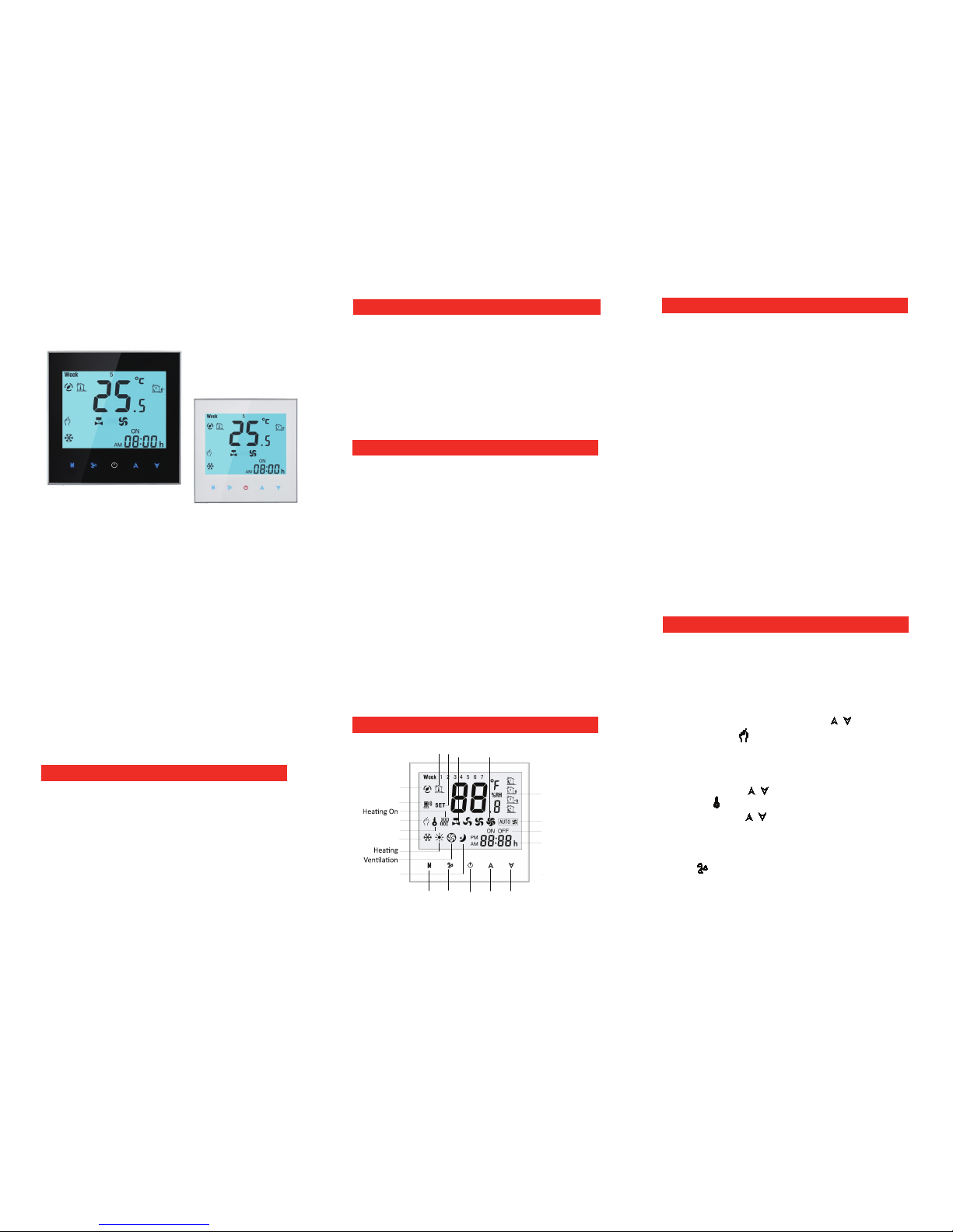
Home screen quick reference
Power
On/off
Up
Fan
Mode
Clock
Auto Fan
Timing On/Off
Cooling
Energysaving
Network
Room
Temp.
Fan
Speed
Manual
Lock
Period
Sleeping
Valve
On/off
Down
Set
Temp.
Operation
1. Setting the temperature
a. In the mode of programmable, set
temperature, time and timing on/off could not be
adjusted. If the user want to change, please
reprogram.
b. In the mode of manual, press to set
temperature. will display in the left corner of
screen.
2. Setting Lock (optional function)
Press and hold for 3 sec. to lock the screen.
The icon will display on the screen.
Press and hold again for 3 sec. to unlock the
screen.
3. Setting the fan
Press to select the fan speed AUTO, HIGH,
MED, LOW.
Technical Data of your thermostat
Sensor:NTC Accuracy:±0.5℃
Temp. Range:5 -35℃ Power Consumption:<1.5W
Timing error:<1% Power Supply:110~240V, 50 ~60Hz
Current Load:1A(Inductive), 2A(Resistance)
Shell Material:PC (Fireproof)
Dimension:86x86x13.3mm
Installation box:86*86mm or European 60mm
Ambient Temp.:0 ~ 45℃,5 ~ 95%RH(Non condensing)
Storage Temp:-5~ 55℃
P and N could not be compatible at the same time.
Page 2
Installing your thermostat
4. Setting the system mode
Press M to change the system mode HEATING,
COOLING and VENTILATION. In the mode of
VENTILATION, the valve is off but the fan runs.
5. Setting the Sleeping
Press and Hold M to set the sleeping. will flash.
Press to confirm, to cancel.
8. Setting functions and options
During power off, press and hold at the same
time for 5 sec. to system functions. Then press M
to change the different items.
All the settings will
confirm automatically when
This product is suitable for standard 86mm wall
box or european 60mm round box.
1. Connect the wire of power and other equipment into
the terminals.
2. Fix the wall plate into the wall box by a screwdriver.
3. Connect the LCD board into the wall plate.
4. Finished.
(Fig 1)
(Fig 2)
(Fig 4)
(Fig 3)
WARNING: Please arrange the professional technician
to install this product according to installation drawing and
instruction.
RISK OF ELECTRICAL SHOCK. Disconnect power supply
before making electrical connection. Contact with components
carrying hazardous voltage can cause electrical shock and may
result in severe personal injury or death.instruction.
6.Selecting manual and programmable
Press and hold , will flash. Press again, M
Press to select manual and press
to select weekly programmable.
7. Adjusting the weekly programmable
Then press M to change the different items.
The order is Minute adjusting→ Hour adjusting
→ Week adjusting→ Minute timing-on → Hour
timing-on→ Minute timing-off→ Hour timing-off→
Temperature adjusting (
“12345”,”6”,”7”, is “5+1+1” programmable mode,
every mode has two times zones and a time
temperature setting)
Week
First Period Second Period
Turn-on
me
Turn-off
me
Set
temp.
Turn-on
me
Turn-off
me
Set
temp.
Mon. to Fri. 1 2 3 4 5 6
Sat. 7 8 9 10 11 12
Sun. 13 14 15 16 17 18
M
will flash.
Press to set minutes of the time;
Press to set hours of the time;
Press to set week of the time;
M
M
M
Press into the adjustment of programmable.M
After the above steps, press into programmable.M
Press or to set the relative values.
No Func on Se ng & Op ons Default
1
Temp.
Calibra
on
-9℃ to 9℃
-1
2
Fan Control
00: When room temp. reaches
the setpoint, the fan will turn
off.
01: When room temp. reaches
the setpoint, the fan will turn
to low speed.
00
3
Lock
00:All the bu
ons are locked
except POWER
01 :All the bu
ons are locked
00
4 Heat/Cool
00:Cool only
01:Heat/Cool
01
5 Min. Set Temp. 5-15℃ 10
6 Max. Set Temp. 5-35℃ 30
7 Time Display
00:12 hours
01:24 hours
00
8
Display mode
01:display set temp. only
00:display both set temp. and
room temp.
00
9 IP low address 01_F9 01
A I P high address 00_F9 00
B
Deadzone
Temp.
1-5℃
1
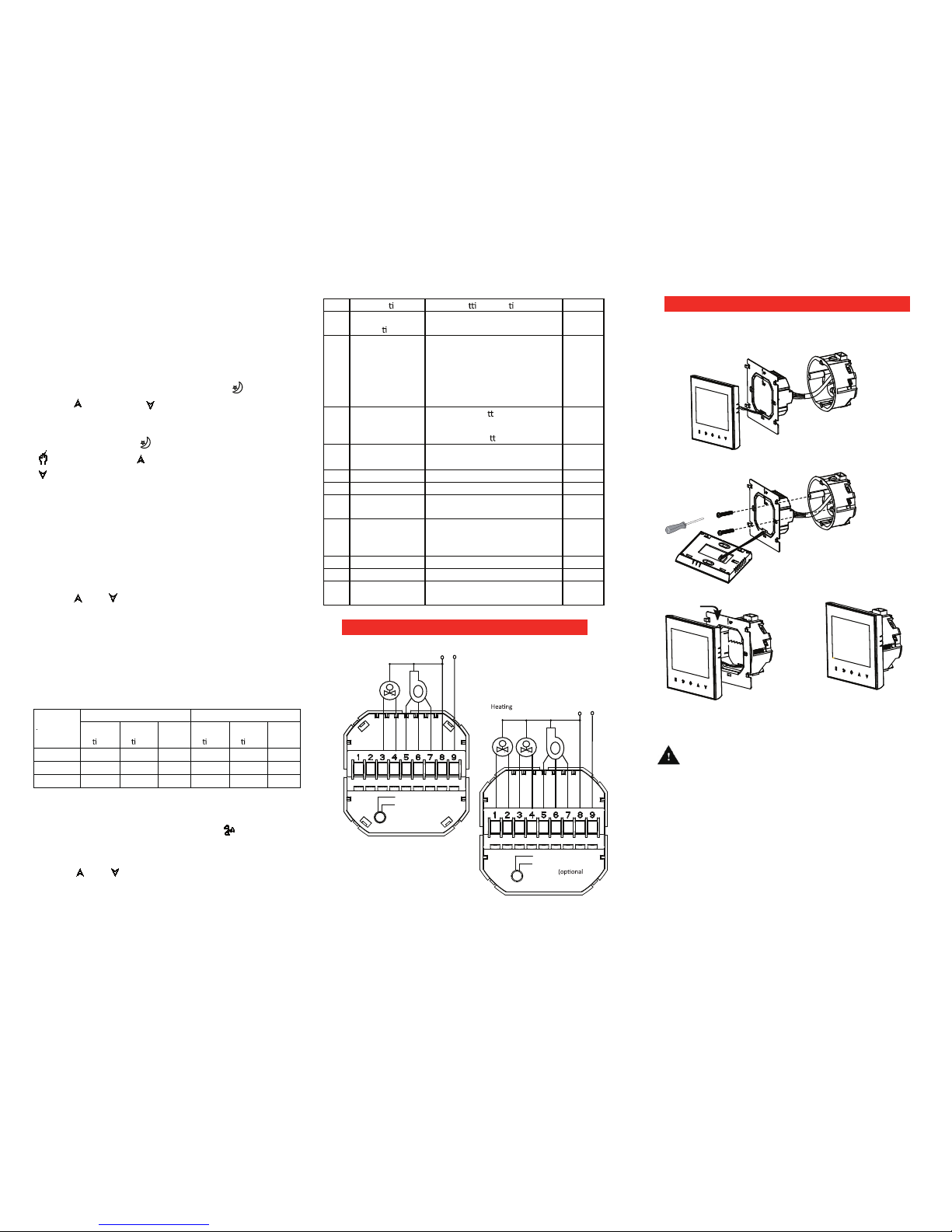
Wiring your thermostat
L
N
M
Valve
(RED)RS485+
(WHITE)RS485-
AC220V 50~60Hz
Fan
M
Press or to set the relative values.
power is on.
High
Med
Low
Open
Close
(RS485 is optional)
Remark: Programmable won’t be working for RS485 type.
(Only for RS485 type)
(Only for RS485 type)
Close
L
N
M
M
Valve
(RED)RS485+
(WHITE)RS485-
)
Cooling
Valve
Fan
Open
Close
Open
Low
Med
High
Two Pipe System
AC220V 50~60Hz
Four Pipe System
 Loading...