

Page 1
Product Catalog
Air-Cooled Scroll Chillers
Model CGAM - Made in USA
20-130 NominalTons (50 Hz and 60 Hz)
February 2015
CG-PRC017H-EN
Page 2

Introduction
Design and manufacturing excellence makesTrane a leader in the air-cooled chiller market place.
This tradition of using excellence to meet market demands is illustrated with the newTrane 20-130
ton nominal air-cooled chiller.The introduction of this next-generation chiller is an exciting step
forward in energy-efficiency,sound, reliability,ease of serviceability, control precision, application
versatility, and operational cost-effectiveness.The new chiller is designed to deliver provenTrane
performance based on the redesign of a European model that has been a market leader, plus all
the benefits of new heat transfer and fan designs, as well as, low-speed, direct-drive scroll
compressors.
Important Design Advances and New Features
• Higher full-load and part-load energy efficiency that exceeds ASHRAE 90.1 and reduces
• Significantly lower noise levels than other scroll compressor chillers.
• HFC-410A optimized design.
• Flow switch and water strainer are factory installed in the optimum locations for seamless
• Trane CH530™ with Adaptive Controls™ have improved fan algorithms for more reliable
• Single chiller time of day scheduling communication for easier control of small jobs.
• Easily integrated with existing BAS via BACnet™ or LonTalk™ communication interface.
• All major service components are close to the unit edge for safe and easy maintenance.
• The chiller is designed for easy serviceability with input from our extended experience in
operating costs.
operation and reduced chiller installation and maintenance time.
operation at extreme conditions.
design, testing and field operation.
Copyright
This document and the information in it are the property ofTrane, and may not be used or
reproduced in whole or in part without written permission.Trane reserves the right to revise this
publication at any time, and to make changes to its content without obligation to notify any person
of such revision or change.
Trademarks
All trademarks referenced in this document are the trademarks of their respective owners.
Revision History
CG-PRC017H-EN (23 Feb 2015)
Added high efficiency option.
© 2015Trane All rights reserved CG-PRC017H-EN
Page 3

Table of Contents
Table of Contents ..................................................3
Features and Benefits ..............................................4
Application Considerations ..........................................6
Model Number Descriptions ........................................13
General Data .....................................................15
Performance Data ................................................23
Controls ........................................................ 31
Electrical ........................................................35
Electrical Connections .............................................40
Dimensions ......................................................44
Weights .........................................................57
Mechanical Specifications ..........................................59
CG-PRC017H-EN 3
Page 4

Features and Benefits
Reliability
• Years of laboratory testing, including running the chiller at extreme operating conditions, have
resulted in optimized compressor and chiller systems reliability by confirming a robust design
and verifying quality each step of the way.
• Direct-drive, low-speed scroll compressors with fewer moving parts provide maximum
efficiency, highreliability, and low maintenance requirements. Suction gas-cooledmotor stays
at a uniformly low temperature for long motor life.
• The third generation microprocessor control system provides improved control capabilities
with Adaptive Control™ to keep the unit operating even in adverse conditions. Advanced
microelectronics protect both the compressor and the motor from typical electrical fault
conditions like thermal overload and phase rotation.
• Standard factory-installed water strainer helps prevent system debris from affecting unit flow
or heat transfer.
• Flow switch is factory-installed at the optimum location in the piping for reduced chiller
installation cost and superior flow sensing, reducing the potential for nuisance trips.
• Exceptionally rigid condenser coil structure is manufactured with hairpin tubes which halves
the number of braze joints significantly reducing the potential for leaks.
• Innovative condenser pressure integrated fan control algorithms and variable frequency drive
on circuits’ lead fans provides more reliable operation at extreme temperature conditions.
Life Cycle Cost-Effectiveness
• Industry leading full- and part-load efficiency
• Electronic expansion valve and high speed suction temperature sensor enables tight chilled
water temperature control and lowsuperheat, resulting in more efficient full-load and part-load
operation than previously available.
• Partial heat recovery available to save energy on pre-heat or reheat applications.
• Pump package features standard variable speed drive on the pump motors eliminating the
need for energy sapping chilled water system triple duty or balancing valves. Additionally,
system commissioning and flexibility is greatly enhanced. Chilled water supply reliability is
increased with the dual pump design, due to standard failure/recovery functionality.
Application Versatility
• Industrial/low temperature process cooling - Excellent operating temperature range and
precise control capabilities enable tight control.
• Ice/thermal storage - Utilities and owners benefit from reduced cooling energy cost.The
chiller’s dual setpoint control and industry leading ice energy storage efficiency assures reliable
operation and superior system efficiencyTrane’s partnership with CALMAC, brings a proven
track record of successful installations across many markets; from churches and schools to sky
scrapers and office buildings.
• Partialheat recovery -Anoptional factory-installedheat exchanger provides hot water for many
needs; water preheat and reheatfor enhanced system humidity control are justtwo.This option
reduces operating costs associated with boilers/domestic hot water.
4 CG-PRC017H-EN
Page 5

Simple, Economical Installation
• Standard sound levels are roughly 5-8 dBa less than the previousTrane air-cooled models,
perfect for applying outdoor HVAC equipment in neighborhoods, such as K-12 schools.
• System integration available with LonTalk®or BACnet®through a single twisted-pair wire for
a less expensive translation to an existing building automation system.
• Powder-coated paint provides superior durability, corrosion protection, and is less likely to be
damaged while rigging/lifting/installing the chiller.
• Factory commissioned unit-mounted starter reduces overall job cost and improves system
reliability by eliminating job site design, installation and labor coordination requirements.
Precision Control
• Easily integrated with existing BAS via BACnet or LonTalk communication interfaces.
• Microprocessor-basedTrane CH530 controls monitor and maintain optimal operation of the
chiller and its associated sensors, actuators, relays, and switches, all of which are factoryinstalled and tested prior to shipping.
• Adaptive Control maintains chiller operation under adverse conditions, when many other
chillers might simply shut down. Operating conditions that are compensated for include high
condensing pressure and low suction pressure.
• Advanced microprocessor controls enable variable primary flow applications providingchilled
water temperature control accuracy of ±2°F (1.1°C) for flow changesupto 10 percent per minute,
plus handling of flow changes up to 30 percent per minute with continuous operation.
• Easy-to-use operator interface displays all operating and safety messages, with complete
diagnostics information, on a highly readable panel with a scrolling touch-screen display.
Status and diagnosticmessages are in plain language - no codes to interpret - and areavailable
in 20 languages.
Features and Benefits
Improved Serviceability
• All major serviceable components are close to the edge. Service shutoff valves and water
strainer are conveniently located to enable easy service.
• Waterpiping connections are factory piped tothe edge of the unit to make installation safer and
faster.
• Electronic expansion valve designed so controls can be removed and serviced without
refrigerant handling.
• The optional pump package is designed to be serviced in place.The unit structure includes a
rigging point for pump servicing, making inspection, cleaning and pump seal changes easier.
• High pressure transducer and temperature sensors mountings enable troubleshooting and
replacement without removing refrigerant charge, greatly improving serviceability over the life
of the unit.
• Dead front panel construction provides for enhanced service technician safety.
CG-PRC017H-EN 5
Page 6

Application Considerations
Certain application constraints should be considered when sizing, selecting and installingTrane
CGAM chillers. Unit and system reliability is often dependent upon proper and complete
compliance with these considerations.Wheretheapplicationvariesfromthe guidelines presented,
it should be reviewed with your localTrane account manager.
Note: The terms water and solution are used interchangeably in the following paragraphs.
Unit Sizing
Unit capacities are listed in the Performance Data section. Intentionally over-sizing a unit to assure
adequate capacity is not recommended. Erratic system operation and excessive compressor
cycling are often a direct result ofan oversized chiller. In addition, an oversized unit is usually more
expensive to purchase, install, and operate. If over sizing is desired consider using two smaller
units.
WaterTreatment
The use of untreated or improperly treated water in chillers may result in scaling, erosion,
corrosion, and algae or slime buildup.This will adversely affect heat transfer between the water
and system components. Proper water treatment must be determined locally and depends on the
type of system and local water characteristics.
Neither salt nor brackish water is recommend for use inTrane air-cooled CGAM chillers. Use of
either will lead toa shortenedlife.Trane encourages the employment of a qualifiedwater treatment
specialist, familiar with local water conditions, to assist in the establishment of a proper water
treatment program.
Foreign matter in the chilled water system can also increase pressure drop and, consequently,
reduce water flow. For this reason it is important to thoroughly flush all water piping to the unit
before making the final piping connections to the unit.
The capacities give in the Performance Data section of this catalog are based on water with a
fouling factor of 0.0001°F·ft²·h/Btu (in accordance withAHRI550/590).For capacities at other fouling
factors, see Performance Selection Software.
Effect of Altitude on Capacity
Chiller capacities given in the Performance Data section are based upon application at sea level.
At elevations substantially above sea level, the decreased air density will decrease condenser
capacity and, therefore, unit capacity and efficiency.
Ambient Limitations
Trane chillers are designed for year-round operation over a range of ambient temperatures.The air-
cooled model CGAM chiller will operate in ambient temperatures of 32°F to 125°F (0°C to 52°C) for
high ambient or 0°F to 125°F (-18°C to 52°C) for wide ambient. Operation down to 0°F requires the
use of variable speed fans to modulate and maintain system differential pressure.
The minimum ambient temperatures are based on still conditions (winds not exceeding five mph).
Greater wind velocities will result in a drop in head pressure, therefore increasing the minimum
starting and operating ambient temperature.TheAdaptive Control™ microprocessor will attempt
to keep the chiller on-line when high or low ambient conditions exist, making every effort to avoid
nuisance trip-outs and provide the maximum allowable tonnage.
6 CG-PRC017H-EN
Page 7
Water Flow Limits
The minimum water flow rates are given in the General Data section of this catalog. Evaporator
flow rates below the tabulated values will result in laminar flow causing freeze-up problems,
scaling, stratification and poor control.The maximum evaporator water flow rate is also given.
Flow rates exceeding those listed may result in very high pressure drop across the evaporator.
Flow Rates Out of Range
Many process cooling jobs require flow rates that cannot be met with the minimum and maximum
published values within the CGAM evaporator. A simple piping change can alleviate this problem.
For example: a plastic injection molding process requires 80 gpm (5.0 l/s) of 50°F (10°C) water and
returns that water at 60°F (15.6°C).The selected chiller can operate at these temperatures, but has
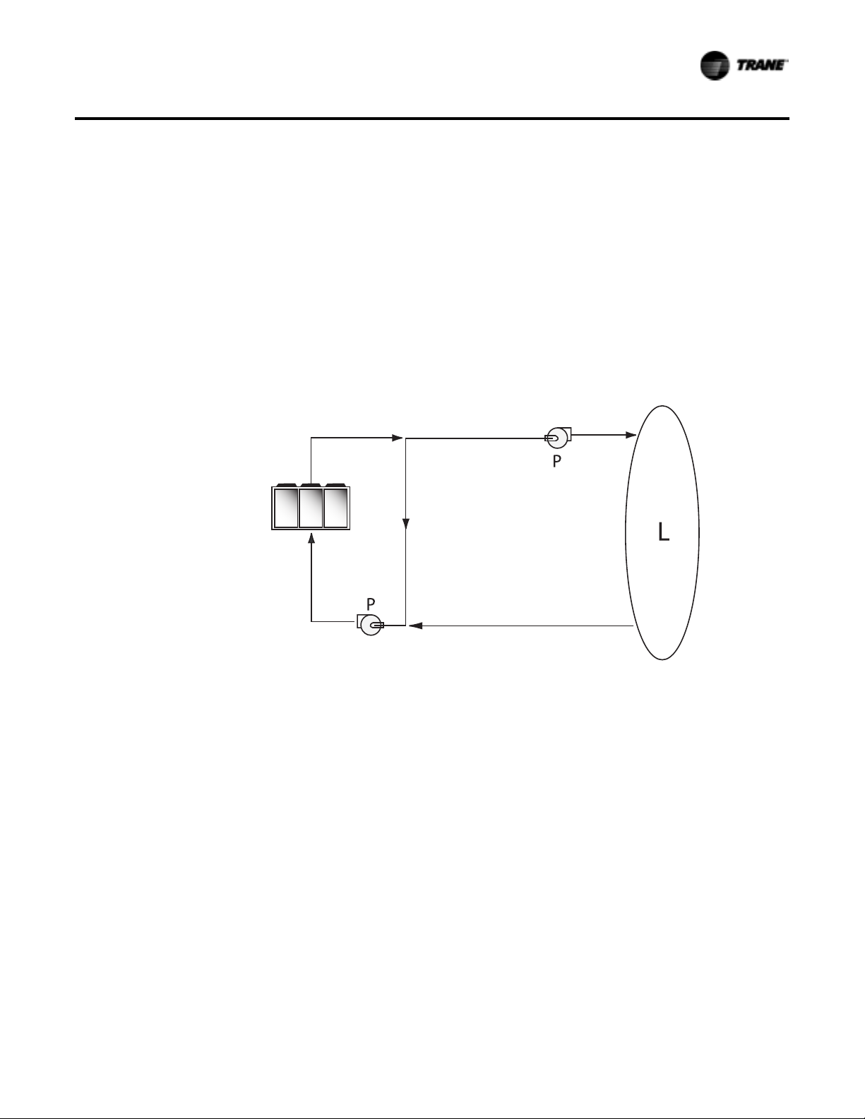
a minimum flow rate of 106 gpm (6.6 l/s).The system layout in Figure 1 can satisfy the process.
Figure 1. Flow rate out of range systems solution
50°F (10°C)
112 gpm (7 l/s)
Application Considerations
50°F (10°C)
80 gpm (5 l/s)
50°F (10°C)
32 gpm (2 l/s)
57°F (14°C)
112 gpm (7 l/s)
Flow Proving
Trane provides a factory-installed water flow switch monitored by CH530 which protects the chiller
from operating in loss of flow conditions.
Variable Flow in the Evaporator
An attractive chilled water system option may be a Variable Primary Flow (VPF) system. VPF
systems present building owners with several cost-saving benefits when compared with Primary/
Secondary chilled water systems.The most obvious cost savings results from eliminating the
constant volume chiller pump(s), which in turn eliminates the related expenses of the associated
piping connections (material, labor), and electrical service and switch gear. In addition to the
installed cost advantage building owners often cite pump related energy savings as the reasons
that prompted them to select a VPF system.
The CGAM has the capability to handle variable evaporator flow without losing leaving water
temperature control.The microprocessor and capacity control algorithms are designed to take a
10 percent change in water flow rate per minute while maintaining a ±2°F (1.1°C) leaving water
temperature control accuracy.The chiller tolerates up to 30 percent per minute waterflow variation
as long as the flow is equal or above the minimum flow rate requirement.
With the help of a software analysis tool such as System Analyzer™, DOE-2 orTRACE™, you can
determine whether the anticipated energy savings justify the use of variable primary flow in a
particular application. Existing constant flow chilled water systems may be relatively easily
converted to VPF and benefit greatly from the inherent efficiency advantages.
60°F (15.6°C)
80 gpm (5 l/s)
CG-PRC017H-EN 7
Page 8
Application Considerations
WaterTemperature
Leaving Water Temperature Limits
Trane CGAM chillers have three distinct leaving water categories:
• standard, with a leaving solution range of 42 to 65°F (5.5 to 18°C)
• low temperature process cooling, with leaving solution range of 10 to 65°F (-12 to 18°C)
• ice-making, with leaving solution range of 20 to 65°F (-7 to 18°C)
Since leaving solution temperature below 42°F (5.5°C) results in suction temperature at or below
the freezing point of water, a glycol solution is required for all low temperature and ice-making
machines. Ice making control includes dual setpoint controls and safeties for ice making and
standard cooling capabilities. Consult your localTrane account manager for applications or
selections involving low temperature or ice making machines.
The maximum water temperature that can be circulated through the CGAM evaporator when the
unit is not operating is 125°F (51.7°C). Evaporator damage may result above this temperature.
Leaving Water Temperature Out of Range
Similar to the flow rate limitations above, many process cooling jobs require temperature ranges
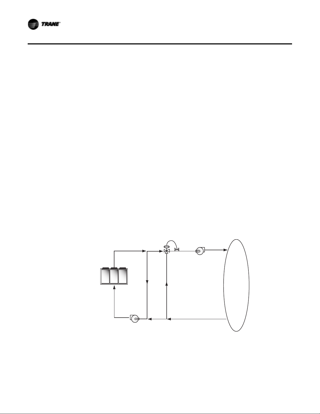
that are outside the allowable minimum and maximum operating values for the chiller. Figure 2
below shows a simple example of a mixed water piping arrangement change that can permit
reliable chiller operation while meeting such cooling conditions. For example, a laboratory load
requires 238 gpm (5 l/s) of water entering the process at 86°F (30°C) and returning at 95°F (35°C).
The chiller’s maximum leaving chilled water temperature of 65°F (15.6°C) prevents direct supply to
the load. In the example shown, both the chiller and process flow rates are equal, however, this is
not necessary. For example, if the chiller had a higher flow rate, there would simply be more water
bypassing and mixing with warm water returning to the chiller.
Figure 2. Temperature out of range system solution
59°F (15°C)
238 gpm (15 l/s)
68°F (20°C)
238 gpm (15 l/s)
Supply WaterTemperature Drop
The cataloged performance datafor theTraneCGAM chiller is based ona chilled water temperature
drop of 10°F (6°C) for I-P data and 9°F (5°C) for SI data. Full load chilled water temperature drops
from 6 to 18°F (3.3 to 10°C) may be used as long as minimum and maximum water temperature
and minimum and maximum flow rates are not violated.Temperature drops outside this range at
full load conditions are beyond the optimum range for control and may adversely affect the
59°F (15°C)
60 gpm (3.8 l/s)
59°F
(15°C)
178 gpm
(11.2 l/s)
P
95°F (35°C)
60 gpm (3.8 l/s)
95°F
(35°C)
178 gpm
(11.2 l/s)
86°F (30°C)
238 gpm
(15 l/s)
P
L
95°F (35°C)
238 gpm (15 l/s)
8 CG-PRC017H-EN
Page 9

microcomputer’s ability to maintain an acceptable supply water temperature range. Furthermore,
full load temperature drops of less than 6°F (3.3°C) may result in inadequate refrigerant superheat
which is critical to long term efficient and reliable operation. Sufficient superheat is always a
primary concern in any refrigerant system and is especially important in a packaged chiller where
the evaporator is closely coupled to the compressor.
Typical Water Piping
All building water piping must be flushed prior to making final connections to the chiller.To reduce
heat loss and prevent condensation,insulation should be applied.Expansion tanks are alsousually
required so that chilled water volume changes can be accommodated.
Avoidance of Short Water Loops
Adequate chilled water system water volume is an important system design parameter because it
provides for stable chilled water temperature control and helps limit unacceptable short cycling of
chiller compressors.
The chiller’s temperature control sensor is located in the supply (outlet) water connection or pipe.
This location allows the building to act as a buffer to slow the rate of change of the system water
temperature. If there is nota sufficient volume of water in the systemto provide an adequatebuffer,
temperature control can suffer, resulting in erratic system operation and excessive compressor
cycling.
Typically, a two-minute water loop circulation time is sufficient to prevent short water loop issues.
Therefore, as a guideline, ensure the volume of water in the chilled water loop equals or exceeds
two times the evaporator flow rate. For systems with a rapidly changing load profile the amount
of volume should be increased.
If the installed system volume does not meet the above recommendations, the following items
should be given careful consideration to increase the volume of water in thesystem and,therefore,
reduce the rate of change of the return water temperature.
• A volume buffer tank located in the return water piping.
• Larger system supply and return header piping (which also reduces system pressure drop and
pump energy use).
Application Considerations
Minimum water volume for a process application
If a chiller is attached to an on/off load such as a process load, it may be difficult for the controller
to respond quickly enough to the very rapid change in return solution temperature if the system
has only the minimum water volume recommended. Such systems may cause chiller low
temperature safety trips or in the extreme case evaporator freezing. In this case, it may be
necessary to add or increase the size of the mixing tank in the return line.
Multiple Unit Operation
Whenever two or more units are used on one chilled water loop,Trane recommends that their
operation be coordinated with a higher level system controller for best system efficiency and
reliability.The TraneTracer system has advanced chilled plant control capabilities designed to
provide such operation.
Ice Storage Operation
An ice storage system uses the chiller to make ice at night when utilities generate electricity more
efficiently and charge less for electricity with lower demand and energy charges.The stored ice
reduces or even replaces mechanical cooling during the day when utility rates are at their highest.
This reduced need for cooling results in significant utility cost savings and source energy savings.
CG-PRC017H-EN 9
Page 10

Application Considerations
Another advantage of an ice storage system is its ability to eliminate chiller over sizing. A
“rightsized” chiller plant with ice storage operates more efficiently with smaller support equipment
while lowering the connected load and reducing operating costs. Best of all this system still
provides a capacity safety factor and redundancy by building it into the ice storage capacity for
practically no cost compared to over sized systems.
TheTrane air-cooled chiller is uniquely suited to low temperature applications like ice storage
because of the ambient relief experienced at night. Chiller ice making efficiencies are typically
similar to or even better than standard cooling daytime efficiencies as a result of night-time drybulb ambient relief.
Standard smart control strategies for ice storage systems are another advantage of the CGAM
chiller.The dual mode control functionality are integrated right into the chiller.TraneTracer
building management systems can measure demand and receive pricing signals from the utility
and decide when to use the stored cooling and when to use the chiller.
Partial Heat Recovery Operation
Partial heat recovery is designed to salvage a portion of the heat that is normally rejected to the
atmosphere through the air-cooled condenser coil and put it to beneficial use.With the addition of
a heat recovery cycle, heat removed from the building cooling load can be transferred to a preheat
application. Keep in mind that the heat recovery cycle is only possible if a cooling load exists to act
as a heat source.
To provide a heat recovery cycle, a supplemental heat exchanger is mounted in series to the air-
cooled condenser.The supplemental heat exchanger is piped into a preheat circuit. During the heat
recovery cycle, the unit operates just as it does in the cooling-only mode except that a portion of
the cooling load heat is rejected to the water heating circuit rather than to the air through the aircooled condenser. Water circulated through the heat recovery heat exchanger by the pumps
absorbs cooling load heat from the compressed refrigerant gas discharged by the compressors.
The heated water is then used to satisfy heating requirements.
Partial heat recovery can be used in applications where hot water is needed for use in kitchens,
lavatories, etc. It is comparatively smaller in size and its heating capacity is not controlled.The
partial heat recovery heat exchanger cannot operate alone without a load on the chiller.
The partial heat recovery heat exchanger can get up to 157°F (69.4°C) leaving temperature. For
more information see the Performance Selection Program.
Unit Placement
SettingThe Unit
A base or foundation is not required if the selected unit location is level and strong enough to
support the unit’s operating weight (see “Weights” section of this catalog).
For a detailed discussion of base and foundation construction, refer to the sound engineering
bulletin or the unit IOM. Manuals are available through the localTrane office.
HVAC equipment must be located to minimize sound and vibration transmission to the occupied
spaces of the building structure it serves. If the equipment must be located in close proximity to
a building, it should be placed next to an unoccupied space such as a storage room, mechanical
room, etc. It is not recommended to locate the equipment near occupied, sound sensitive areas of
the building or near windows. Locating the equipment away from structures will also prevent
sound reflection, which can increase sound levels at property lines or other sensitive points.
10 CG-PRC017H-EN
Page 11
Isolation and Sound Emission
Structurally transmitted sound can be reduced by elastomeric vibration eliminators. Elastomeric
isolators are generally effective in reducing vibratory noise generated by compressors, and
therefore, are recommended for sound sensitive installations. An acoustical engineer should
always be consulted on critical applications.
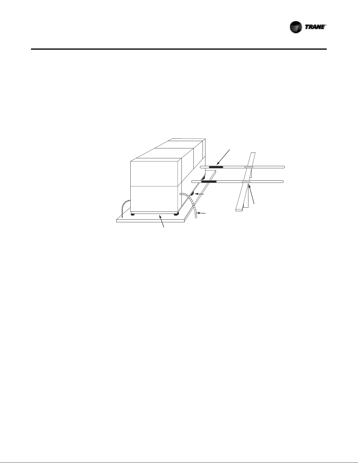
Figure 3. Installation example
Application Considerations
Piping isolation
Servicing
Chilled water piping
supported.should be
Isolators
Isolators
Flexible electrical
conduit
Concrete base
For maximum isolation effect, water lines and electrical conduit should also be isolated.Wall
sleeves and rubber isolated piping hangers can be used to reduce the sound transmitted through
water piping.To reduce the sound transmitted through electrical conduit, use flexible electrical
conduit.
Local codes on sound emissions should always be considered. Since the environment in which a
sound source is located affects sound pressure, unitplacement must be carefullyevaluated. Sound
power levels for chillers are available on request.
Adequate clearance for evaporator and compressor servicing should be provided. Recommended
minimum space envelopes for servicing are located in the dimensional data section and can serve
as a guideline for providing adequate clearance.The minimum space envelopes also allow for
control panel door swing and routine maintenance requirements. Local code requirements may
take precedence.
CG-PRC017H-EN 11
Page 12

Application Considerations
Unit Location
General
Unobstructed flow of condenser air is essential to maintain chiller capacity and operating
efficiency. When determining unit placement, careful consideration must be given to assure a
sufficient flow of air across the condenser heat transfer surface.Two detrimental conditions are
possible and must be avoided: warm air recirculation and coil starvation. Air recirculation occurs
when discharge air from the condenser fans is recycled back to the condenser coil inlet. Coil
starvation occurs when free airflow to the condenser is restricted.
Condenser coils and fan discharge must be kept free of snow or other obstructions to permit
adequate airflow for satisfactory unit operation. Debris, trash, supplies, etc., should not be allowed
to accumulate in the vicinity of the air-cooled chiller. Supply air movement may draw debris into
the condenser coil, blocking spaces between coil fins and causing coil starvation.
Both warm air recirculation and coil starvation cause reductions in unit efficiency and capacity
because of the higher head pressures associated with them.The air-cooled CGAM chiller offers an
advantage over competitive equipment in these situations. Operation is minimally affected in
many restricted air flow situations due to its advanced Adaptive Control™ microprocessor which
has the ability to understand the operating environment of the chiller and adapt to it by first
optimizing its performance and then staying on line through abnormal conditions. For example,
high ambient temperatures combined with a restricted air flow situation will generally not cause
the air-cooled model CGAMchiller to shut down. Otherchillers would typically shutdown on ahigh
pressure nuisance cut-out in these conditions.
Cross winds, those perpendicular to the condenser, tend to aid efficient operation in warmer
ambient conditions. However, they tend to be detrimental to operation in lower ambients due to
the accompanying loss of adequate head pressure. Special consideration should be given to low
ambient units. As a result, it is advisable to protect air-cooled chillers from continuous direct winds
exceeding 10 mph (4.5 m/s) in low ambient conditions.
The recommended lateral clearances are depicted in the close spacing engineering bulletin
available from your local office.
Provide Sufficient Unit-to-Unit Clearance
Units should be separated from each other by sufficient distance to prevent warm air recirculation
or coil starvation. Doubling the recommended single unit air-cooled chiller clearances will
generally prove to be adequate.
Walled Enclosure Installations
When the unit is placed in an enclosure or small depression, the top of the surrounding walls
should be no higher than the top of the fans.The chiller should be completely open above the fan
deck.There should be no roof or structure covering the top of the chiller. Ducting individual fans
is not recommended.
12 CG-PRC017H-EN
Page 13

Model Number Descriptions
Digits 1-4— Chiller Model
CGAM= Air-Cooled Scroll Packaged
Chiller
Digits 5-7— Unit Nominal Ton
020 = 20Tons
026 = 26Tons
030 = 30Tons
035 = 35Tons
040 = 40Tons
052 = 52Tons
060 = 60Tons
070 = 70Tons
080 = 80Tons
090 = 90Tons
100 = 10 0Ton s
110 = 11 0 T o n s
120 = 120 Tons
130 = 130 Tons
Digit 8— Unit Voltage
A = 208Volt 60 Hz 3 Phase
B = 230 Volt 60 Hz 3 Phase
D = 380 Volt 60 Hz 3 Phase
E = 400 Volt 50 Hz 3 Phase
F = 460 Volt 60 Hz 3 Phase
G = 575 Volt 60 Hz 3 Phase
Digit 9— Manufacturing Plant
2 = Pueblo, USA
Digits 10-11— Design Sequence
** = Factory/ABU Assigned
Digit 12— Unit Type
2 = High Efficiency
3 = Extra Efficiency
Digit 13— Agency Listing
X = No Agency Listing
A = UL Listed to U.S. and
Canadian Safety Standard
Digit 14— Pressure Vessel Code
X = No Pressure VesselCode
Digit 15— Unit Application
B = High Ambient (32-125°F/0-52°C)
D = Wide Ambient
(0-125°F/-18-52°C)
Digit 16— Refrigerant Isolation
Valves
2 = Refrigerant Isolation Valves
(Discharge Valve)
Digit 17— Seismically Rated
A = Not Seismically Rated Unit
B = IBC Seismically Rated Unit
C = OSHPD Seismically Rated Unit
Digit 18— Freeze Protection
(Factor-Installed Only)
X = Without Freeze Protection
1 = With Freeze Protection
(ExternalT-Stat Control)
Digit 19— Insulation
A = Factory Insulation - All Cold Parts
B = Insulation for High Humidity/
Low EvapTemp
Digit 20— Factory Charge
1 = Full Factory Refrigerant Charge
(HFC R-410A)
2 = Nitrogen Charge
Digit 21— Evaporator
Application
A = Standard Cooling
(42 to 65°F/5.5 to 18°C)
B = Low Temperature Processing
(lower than 42°F/5.5°C)
C = Ice-Making - Hardwired Interface
(20 to 65°F/-7 to 18°C)
Digit 22— Water Connections
1 = Grooved Pipe Connection
Digit 23— Condenser Fin
Material
A = Lanced Aluminum Fins
C = Non-Lanced Copper Fins
D = Lanced Aluminum Fins
w/ CompleteCoat™
Digit 24— Condenser Heat
Recovery
X = No Heat Recovery
1 = Partial Heat Recovery with
Fan Control
Digit 25— Not Used
X
Digit 26— Starter Type
A = Across the Line Starter/
Direct on Line
Digit 27— Incoming Power Line
Connection
1 = Single Point Power Connection
Digit 28— Power Line
Connection Type
A = Terminal Block
C = Circuit Breaker
D = Circuit Breaker with High Fault
Rated Control Panel
Digit 29— Enclosure Type
1 = Water Tight (per UL 1995
Standard)
Digit 30— Unit Operator
Interface
A = Dyna-View/English
Digit 31— Remote Interface
(Digital Comm)
X = No Remote Digital
Communication
2 = LonTalk®/Tracer Summit Interface
3 = Time of Day Scheduling
4 = BACNet®Interface
Digit 32— External Chilled/Hot
Water and Current Demand Limit
Setpoint
X = No External Chilled Water
Setpoint
A = External Chilled Water and
Demand Limit Setpoint 4-20mA
B = External Chilled Water and
Demand Limit Setpoint 2-10Vdc
Digit 33— Percent Capacity
X = Without % Capacity
1 = With % Capacity
Digit 34— Programmable Relays
X = No Programmable Relays
A = Programmable Relays
Digit 35— Pump Type
X = No Pumps and No Contactors
8 = Dual High Head Pump
Digit 36— Pump Flow Control
X = No Pump Control
B = Pump Flow Controlled by
Variable Speed Drive
Digit 37— Buffer Tank
X = No BufferTank
1 = With Buffer Tank
Digit 38— Short Circuit Rating
X = No Short Circuit Rating
A = Default A Short Circuit Rating
B = High A Short Circuit Rating
Digit 39— Installation
Accessories
X = No Installation Accessories
1 = Elastomeric Isolators
3 = Seismically Rated Isolators
Digit 40— Water Strainer
A = With Water Strainer Factory
Installed
Digit 41— Sound Attenuator
Package
3 = Super Quiet
5 = Comprehensive Acoustic
Package
Digit 42— Appearance Options
X = No Appearance Options
A = Architectural Louvered Panels
B = Half Louvers
CG-PRC017H-EN 13
Page 14

Model Number Descriptions
Digit 43— Exterior Finish
1 = Standard Paint
Digit 44— Label, Literature
Language
B = Spanish
D = English
E = French and English
Digit 45— Phase Reversal
Protection
1 = Phase Reversal Protection
Digit 46— Shipping Package
X = No Skid (Standard)
A = Unit Containerization Package
Digit 47— PerformanceTest
Options
X = No PerformanceTest
2 = 1 Point Test with Report
3 = Witness Test with Report
Digit 48— Flow Switch Set Point
C = Flow Switch Set Point 15
F = Flow Switch Set Point 35
H = Flow Switch Set Point 45
L = Flow Switch Set Point 60
Digit 49— Not Used
X
Digit 50— Specials
X = None
S = Special
Note: If a digit is not defined it may be
held for future use.
14 CG-PRC017H-EN
Page 15

General Data
Table 1. General data - 60 Hz - high efficiency - IP
Size 20 26 30 35 40 52 60 70 80 90 100 110 120 130
Compressor
Number # 2 2 2 2 4 4 4 4 4 4 4 4 4 6
25-5075-100
20+20
+25
15-3146-62-
81-100
Tonnage/circuit¹ 10+10 13+13 15+15 15+20 10+10 13+13 15+15 15+20 20+20 20+25 25+25 25+30 30+30
Evaporator
Water storage (gal) 1.4 2.2 2.2 3.2 2.4 4.1 5.0 7.5 7.0 9.0 10.3 11.5 11.5 12.3
Min. flow (gpm) 30 38 42 50 57 74 84 100 115 129 145 157 170 184
Max. flow (gpm) 69 89 100 117 136 176 201 238 275 307 346 375 407 440
Water connection (in) 2 2.5 2.5 2.5 3 3 3 3 4 4 4 4 4 4
Condenser
Quantity of coils # 1 1 1 1 2 2 2 2 4 4 4 4 4 4
Coil length (in) 91 91 127 127 91 91 127 127 121 121 144 144 144 180
Coil height (in) 68 68 68 68 68 68 68 68 42 42 42 42 42 42
Number of rows # 2 2 2 2 2 2 2 2 3 3 3 3 3 3
Fins per foot (fpf) 192 192 192 192 192 192 192 192 192 192 192 192 192 192
Fan
Quantity # 2 2 3 3 4 4 6 6 6 6 8 8 8 10
Diameter (in) 28.8 28.8 28.8 28.8 28.8 28.8 28.8 28.8 28.8 28.8 28.8 28.8 28.8 28.8
Airflow per fan (cfm) 9413 9420 9168 9173 9413 9420 9168 9173 9470 9472 9094 9096 9098 9094
Power per motor (HP) 1.3 1.3 1.3 1.3 1.3 1.3 1.3 1.3 1.3 1.3 1.3 1.3 1.3 1.3
Motor RPM (rpm) 840 840 840 840 840 840 840 840 840 840 840 840 840 840
Tip speed (ft/min) 6333 6333 6333 6333 6333 6333 6333 6333 6333 6333 6333 6333 6333 6333
General Unit
Refrig circuits # 1 1 1 1 2 2 2 2 2 2 2 2 2 2
25-50-
25-50-
25-50-
21-43-
25-50-
22-44-
25-50-
Capacity steps % 50-100 50-100 50-100 43-100
Refrig charge/circuit ¹ (lbs) 32 34 44 48 32 32 44 48 74 78 90 91.5 86 112
Oil charge/circuit¹ (gal) 1.7 1.7 1.9 3.5 1.7 1.7 1.9 3.5 3.5 3.5 3.5 3.7 3.8 5.8
Min ambient - wide (°F) 0 0 0 0 0 0 0 0 0 0 0 0 0 0
Min ambient - high (°F) 32 32 32 32 32 32 32 32 32 32 32 32 32 32
75-100
75-100
75-100
71-100
75-100
72-100
75-100
23-4573-100
Pump Package
Avail head pressure² (ft H2O) 78.2 77.7 71.1 67.6 67.1 58.6 76.7 63.5 82.0 78.1 69.0 61.9 71.3 62.2
Power (HP) 5 5 5 5 5 5 7.5 7.5 10 10 10 10 15 15
Expansion tank
volume
Buffer tank volume (gal) 140 140 140 140 140 140 140 140 152 152 195 195 195 195
(gal) 5 5 5 5 5 5 5 5 6 6 6 6 6 6
Partial Heat Recovery
Water storage/circuit¹ (gal) 0.02 0.02 0.02 0.03 0.02 0.02 0.02 0.03 0.03 0.04 0.04 0.04 0.06 0.06
Max flow (gpm) 39 39 39 39 78 78 78 78 127 127 127 127 127 127
Water connection (in) 1.5 1.5 1.5 1.5 1.5 1.5 1.5 1.5 2.5 2.5 2.5 2.5 2.5 2.5
1. Data shown for circuit one only. The second circuits always matches.
2. Pump available head pressure is based on: 44/54°F evaporator with water, .0001 hr-ft²-°F/Btu, 95°F ambient and 0 ft elevation.
CG-PRC017H-EN 15
Page 16
General Data
Table 2. General data - 60 Hz - high efficiency - SI
Size 20 26 30 35 40 52 60 70 80 90 100 110 120 130
Compressor
Number # 22224444444446
25-5075-100
20+20
+25
15-3146-62-
81-100
Tonnage/circuit¹ 10+10 13+13 15+15 15+20 10+10 13+13 15+15 15+20 20+20 20+25 25+25 25+30 30+30
Evaporator
Water storage (l) 5.3 8.3 8.3 12.1 9.1 15.5 18.9 28.4 26.5 34.1 39.0 43.5 43.5 46.6
Min. flow (l/s) 1.8 2.3 2.6 3.1 3.6 4.6 5.3 6.3 7.2 8.1 9.1 9.9 10.7 11.6
Max. flow (l/s) 4.4 5.6 6.3 7.4 8.6 11.1 12.7 15.1 17.4 19.4 21.9 23.7 25.7 27.8
Water connection (mm) 50.8 63.5 63.5 63.5 76.2 76.2 76.2 76.2 101.6 101.6 101.6 101.6 101.6 101.6
Condenser
Qty of coils # 11112222444444
Coil length (mm) 2311 2311 3226 3226 2311 2311 3226 3226 3073 3073 3658 3658 3658 4572
Coil height (mm) 1727 1727 1727 1727 1727 1727 1727 1727 1067 1067 1067 1067 1067 1067
Number of rows # 22222222333333
Fins per foot (fpf) 192 192 192 192 192 192 192 192 192 192 192 192 192 192
Fan
Quantity # 223344664688810
Diameter (mm) 732 732 732 732 732 732 732 732 732 732 732 732 732 732
Airflow per fan
Power per motor (HP) 1.3 1.3 1.3 1.3 1.3 1.3 1.3 1.3 1.3 1.3 1.3 1.3 1.3 1.3
Motor RPM (rpm) 840 840 840 840 840 840 840 840 840 840 840 840 840 840
Tip speed (m/s) 32 32 32 32 32 32 32 32 32 32 32 32 32 32
(m³/
15993 16005 15577 15585 15993 16005 15577 15585 16090 16093 15451 15454 15458 15451
h)
General Unit
Refrig circuits # 11112222222222
25-50-
25-50-
25-50-
21-43-
25-50-
22-44-
25-50-
Capacity steps % 50-100 50-100 50-100 43-100
Refrig charge/circuit¹ (kg) 14.5 15.4 20 21.8 14.5 14.5 20 21.8 33.6 35.4 40.8 41.5 39.0 50.8
Oil charge /circuit¹ (l) 6.6 6.6 7.2 13.4 6.6 6.6 7.2 13.4 13.4 13.4 13.4 13.9 14.4 22.0
Min ambient - wide (°C) -18 -18 -18 -18 -18 -18 -18 -18 -18 -18 -18 -18 -18 -18
Min ambient - high (°C) 00000000000000
75-100
75-100
75-100
71-100
75-100
72-100
75-100
23-4573-100
Pump Package
Avail head pressure² (kPa) 233.7 232.3 212.6 202.1 200.6 175.0 229.2 189.7 245.1 233.3 206.3 185.0 213.1 185.8
Power (HP) 5555557.57.5101010101515
Expansion tank
volume
Buffer tank volume (l) 530 530 530 530 530 530 530 530 575 575 727 727 727 727
(l) 18.9 18.9 18.9 18.9 18.9 18.9 18.9 18.9 22.7 22.7 22.7 22.7 22.7 22.7
Partial Heat Recovery
Water storage/circuit¹ (l) 0.07 0.09 0.09 0.11 0.07 0.09 0.09 0.11 0.12 0.16 0.16 0.16 0.21 0.21
Max flow (l/s) 2.5 2.5 2.5 2.5 5.0 5.0 5.0 5.0 8.0 8.0 8.0 8.0 8.0 8.0
Water connection (mm) 38.1 38.1 38.1 38.1 38.1 38.1 38.1 38.1 63.5 63.5 63.5 63.5 63.5 63.5
1. Data shown for circuit one only. The second circuit always matches.
2. Pump available head pressure is based on: 6.7/12.2°C evaporator with water, .01761 m²°C/kW, 35°C ambient and 0 m elevation.
16 CG-PRC017H-EN
Page 17
General Data
Table 3. General data - 50 Hz - high efficiency - IP
Size 20 26 30 35 40 52 60 70 80 90 100 110 120
Compressor
Number # 2 2 2 2444444444
Tonnage/circuit¹ 10+10 13+13 15+15 15+20 10+10 13+13 15+15 15+20 20+20 20+25 25+25 25+30 30+30
Evaporator
Water storage (gal) 1.4 2.2 2.2 3.2 2.4 4.1 5.0 7.5 7.0 9.0 10.3 11.5 11.5
Min. flow (gpm) 25 32 36 41 48 62 71 83 97 109 123 133 142
Max. flow (gpm) 59 75 85 98 115 149 170 199 234 262 296 319 341
Water connection (in) 2 2.5 2.5 2.5 3 3 3 3 4 4 4 4 4
Condenser
Quantity of coils # 1 1 1 1222244444
Coil length (in) 91 91 127 127 91 91 127 127 121 121 144 144 144
Coil height (in) 68 68 68 68 68 68 68 68 42 42 42 42 42
Number of rows # 2 2 2 2222233333
Fins per foot (fpf) 192 192 192 192 192 192 192 192 192 192 192 192 192
Fan
Quantity # 2 2 3 3446666888
Diameter (in) 28.8 28.8 28.8 28.8 28.8 28.8 28.8 28.8 28.8 28.8 28.8 28.8 28.8
Airflow/fan (cfm) 7796 7783 7587 7590 7795 7801 7587 7590 7827 7829 7503 7505 7506
Power/motor (HP) 1.3 1.3 1.3 1.3 1.3 1.3 1.3 1.3 1.3 1.3 1.3 1.3 1.3
Motor RPM (rpm) 700 700 700 700 700 700 700 700 700 700 700 700 700
Tip speed
General Unit
Refrig circuits # 1 1 1 1222222222
Capacity steps % 50-100 50-100 50-100 43-100
Refrig charge/circuit¹ (lbs) 34 34 44 48 32 32 44 48 74 78 82 86 84
Oil charge/circuit¹ (gal) 1.7 1.7 1.9 3.5 1.7 1.7 1.9 3.5 3.5 3.5 3.5 3.7 3.8
Min ambient - wide (°F) 0 0 0 0000000000
Min ambient - high (°F) 32 32 32 32 32 32 32 32 32 32 32 32 32
Partial Heat Recovery
Water storage/circuit¹ (gal) 0.02 0.02 0.02 .02 0.02 0.02 0.02 0.02 0.03 0.03 0.03 0.04 0.04
Max flow (gpm) 39 39 39 39 78 78 78 78 127 127 127 127 127
Water connection (in) 1.5 1.5 1.5 1.5 1.5 1.5 1.5 1.5 2.5 2.5 2.5 2.5 2.5
1. Data shown for circuit one only. The second circuits always matches.
(ft/
5278 5278 5278 5278 5278 5278 5278 5278 5278 5278 5278 5278 5278
min)
25-5075-100
25-50-
75-100
25-5075-100
21-4371-100
25-5075-100
22-4472-100
25-5075-100
23-45-
73-100
25-5075-100
CG-PRC017H-EN 17
Page 18
General Data
Table 4. General data - 50 Hz - high efficiency - SI
Size 20 26 30 35 40 52 60 70 80 90 100 110 120
Compressor
Number # 2 2 2 2444444444
Tonnage/circuit¹ 10+10 13+13 15+15 15+20 10+10 13+13 15+15 15+20 20+20 20+25 25+25 25+30 30+30
Evaporator
Water storage (l) 5.3 8.3 8.3 12.1 9.1 15.5 18.9 28.4 26.5 34.1 39.0 43.5 43.5
Min. flow (l/s) 1.6 2.0 2.2 2.6 3.0 3.9 4.4 5.2 6.1 6.8 7.7 8.3 8.9
Max. flow (l/s) 3.7 4.8 5.4 6.2 7.3 9.4 10.8 12.6 14.8 16.5 18.7 20.2 21.6
Water connection (mm) 50.8 63.5 63.5 63.5 76.2 76.2 76.2 76.2 101.6 101.6 101.6 101.6 101.6
Condenser
Quantity of coils # 1 1 1 1222244444
Coil length (mm) 2311 2311 3226 3226 2311 2311 3226 3226 3073 3073 3658 3658 3658
Coil height (mm) 1727 1727 1727 1727 1727 1727 1727 1727 1067 1067 1067 1067 1067
Number of rows # 2 2 2 2222233333
Fins per foot (fpf) 192 192 192 192 192 192 192 192 192 192 192 192 192
Fan
Quantity # 2 2 3 3446666888
Diameter (mm) 732 732 732 732 732 732 732 732 732 732 732 732 732
Airflow/fan
Power/motor (HP) 1.3 1.3 1.3 1.3 1.3 1.3 1.3 1.3 1.3 1.3 1.3 1.3 1.3
Motor RPM (rpm) 700 700 700 700 700 700 700 700 700 700 700 700 700
Tip speed (m/s) 26.8 26.8 26.8 26.8 26.8 26.8 26.8 26.8 26.8 26.8 26.8 26.8 26.8
General Unit
Refrig circuits # 1 1 1 1222222222
Capacity steps % 50-100 50-100 50-100 43-100
Refrig charge/circuit¹ (kg) 15.4 15.4 20 21.8 14.5 14.5 20 21.8 33.6 35.4 37.2 39.0 38.1
Oil charge/circuit ¹ (l) 6.6 6.6 7.2 13.4 6.6 6.6 7.2 13.4 13.4 13.4 13.4 13.9 14.4
Min ambient - wide (°C) -18 -18 -18 -18 -18 -18 -18 -18 -18 -18 -18 -18 -18
Min ambient - high (°C) 0 0 0 0000000000
Partial Heat Recovery
Water storage/circuit¹ (l) 0.07 0.07 0.09 0.09 0.07 0.07 0.09 0.09 0.12 0.12 0.12 0.16 0.16
Max flow (l/s) 2.5 2.5 2.5 2.5 5.0 5.0 5.0 5.0 8.0 8.0 8.0 8.0 8.0
Water connection (mm) 38.1 38.1 38.1 38.1 38.1 38.1 38.1 38.1 63.5 63.5 63.5 63.5 63.5
1. Data shown for circuit one only. The second circuit always matches.
(m³/
13245 13223 12890 12895 13244 13254 12890 12895 13298 13302 12748 12751 12753
h)
25-5075-100
25-5075-100
25-5075-100
21-4371-100
25-5075-100
22-4472-100
25-5075-100
23-4573-100
25-5075-100
18 CG-PRC017H-EN
Page 19
General Data
Table 5. General data - 60 Hz - extra efficiency - IP
Size 20 26 30 35 40 52 60 70
Compressor
Number # 2 2 2 2 4 4 4 4
Tonnage/circuit¹ 10+10 13+13 15+15 15+20 10+10 13+13 15+15 15+20
Evaporator
Water storage (gal) 1.4 2.2 2.2 3.2 2.4 4.1 5.0 7.5
Min. flow (gpm) 30 38 42 50 57 74 84 100
Max. flow (gpm) 69 89 100 117 136 176 201 238
Water connection (in) 2 2.5 2.5 2.5 3 3 3 3
Condenser
Quantity of coils # 1 1 1 1 2 2 2 2
Coil length (in) 91 91 127 127 91 91 127 127
Coil height (in) 68 68 68 68 68 68 68 68
Number of rows # 3 3 3 3 3 3 3 3
Fins per foot (fpf) 192 192 192 192 192 192 192 192
Fan
Quantity # 2 2 3 3 4 4 6 6
Diameter (in) 28.8 28.8 28.8 28.8 28.8 28.8 28.8 28.8
Airflow per fan (cfm) 9413 9420 9168 9173 9413 9420 9168 9173
Power per motor (HP) 1.3 1.3 1.3 1.3 1.3 1.3 1.3 1.3
Motor RPM (rpm) 840 840 840 840 840 840 840 840
Tip speed (ft/min) 6333 6333 6333 6333 6333 6333 6333 6333
General Unit
Refrig circuits # 1 1 1 1 2 2 2 2
Capacity steps % 50-100 50-100 50-100 43-100 25-50-75-100 25-50-75-100 25-50-75-100 21-43-71-100
Refrig charge/circuit ¹ (lbs) 45 48 68 68 42 42 66 62
Oil charge/circuit¹ (gal) 1.7 1.7 1.9 3.5 1.7 1.7 1.9 3.5
Min ambient - wide (°F) 0 0 0 0 0 0 0 0
Min ambient - high (°F) 32 32 32 32 32 32 32 32
Pump Package
Avail head pressure² (ft H2O) 78.2 77.7 71.1 67.6 67.1 58.6 76.7 63.5
Power (HP) 5 5 5 5 5 5 7.5 7.5
Expansion tank
volume
Buffer tank volume (gal) 140 140 140 140 140 140 140 140
Partial Heat Recovery
Water storage/circuit¹ (gal) 0.02 0.02 0.02 0.03 0.02 0.02 0.02 0.03
Max flow (gpm) 39 39 39 39 78 78 78 78
Water connection (in) 1.5 1.5 1.5 1.5 1.5 1.5 1.5 1.5
1. Data shown for circuit one only. The second circuits always matches.
2. Pump available head pressure is based on: 44/54°F evaporator with water, .0001 hr-ft²-°F/Btu, 95°F ambient and 0 ft elevation.
(gal) 5 5 5 5 5 5 5 5
CG-PRC017H-EN 19
Page 20
General Data
Table 6. General data - 60 Hz - extra efficiency - SI
Size 20 26 30 35 40 52 60 70
Compressor
Number # 2222 4444
Tonnage/circuit¹ 10+10 13+13 15+15 15+20 10+10 13+13 15+15 15+20
Evaporator
Water storage (l) 5.3 8.3 8.3 12.1 9.1 15.5 18.9 28.4
Min. flow (l/s) 1.8 2.3 2.6 3.1 3.6 4.6 5.3 6.3
Max. flow (l/s) 4.4 5.6 6.3 7.4 8.6 11.1 12.7 15.1
Water connection (mm) 50.8 63.5 63.5 63.5 76.2 76.2 76.2 76.2
Condenser
Qty of coils # 1111 2222
Coil length (mm) 2311 2311 3226 3226 2311 2311 3226 3226
Coil height (mm) 1727 1727 1727 1727 1727 1727 1727 1727
Number of rows # 3333 3333
Fins per foot (fpf) 192 192 192 192 192 192 192 192
Fan
Quantity # 2233 4466
Diameter (mm) 732 732 732 732 732 732 732 732
Airflow per fan
Power per motor (HP) 1.3 1.3 1.3 1.3 1.3 1.3 1.3 1.3
Motor RPM (rpm) 840 840 840 840 840 840 840 840
Tip speed (m/s) 32 32 32 32 32 32 32 32
General Unit
Refrig circuits # 1111 2222
Capacity steps % 50-100 50-100 50-100 43-100 25-50-75-100 25-50-75-100 25-50-75-100 21-43-71-100
Refrig charge/circuit¹ (kg) 20.3 21.6 30.7 30.7 18.9 18.9 29.8 28.3
Oil charge /circuit¹ (l) 6.6 6.6 7.2 13.4 6.6 6.6 7.2 13.4
Min ambient - wide (°C) -18 -18 -18 -18 -18 -18 -18 -18
Min ambient - high (°C) 0000 0000
Pump Package
Avail head pressure² (kPa) 233.7 232.3 212.6 202.1 200.6 175.0 229.2 189.7
Expansion tank
volume
Buffer tank volume (l) 530 530 530 530 530 530 530 530
Partial Heat Recovery
Water storage/circuit¹ (l) 0.07 0.09 0.09 0.11 0.07 0.09 0.09 0.11
Max flow (l/s) 2.5 2.5 2.5 2.5 5.0 5.0 5.0 5.0
Water connection (mm) 38.1 38.1 38.1 38.1 38.1 38.1 38.1 38.1
1. Data shown for circuit one only. The second circuit always matches.
2. Pump available head pressure is based on: 6.7/12.2°C evaporator with water, .01761 m²°C/kW, 35°C ambient and 0 m elevation.
(m³/
15993 16005 15577 15585 15993 16005 15577 15585
h)
Power (HP) 5555 5 5 7.5 7.5
(l) 18.9 18.9 18.9 18.9 18.9 18.9 18.9 18.9
20 CG-PRC017H-EN
Page 21

General Data
Table 7. General data - 50 Hz - extra efficiency - IP
Size 20 26 30 35 40 52 60 70
Compressor
Number # 2 2 2 2 4444
Tonnage/circuit¹ 10+10 13+13 15+15 15+20 10+10 13+13 15+15 15+20
Evaporator
Water storage (gal) 1.4 2.2 2.2 3.2 2.4 4.1 5.0 7.5
Min. flow (gpm) 25 32 36 41 48 62 71 83
Max. flow (gpm) 59 75 85 98 115 149 170 199
Water connection (in) 2 2.5 2.5 2.5 3333
Condenser
Quantity of coils # 1 1 1 1 2222
Coil length (in) 91 91 127 127 91 91 127 127
Coil height (in) 68 68 68 68 68 68 68 68
Number of rows # 2 2 2 2 2222
Fins per foot (fpf) 192 192 192 192 192 192 192 192
Fan
Quantity # 2 2 3 3 4466
Diameter (in) 28.8 28.8 28.8 28.8 28.8 28.8 28.8 28.8
Airflow/fan (cfm) 7796 7783 7587 7590 7795 7801 7587 7590
Power/motor (HP) 1.3 1.3 1.3 1.3 1.3 1.3 1.3 1.3
Motor RPM (rpm) 700 700 700 700 700 700 700 700
Tip speed (ft/min) 5278 5278 5278 5278 5278 5278 5278 5278
General Unit
Refrig circuits # 1 1 1 1 2222
Capacity steps % 50-100 50-100 50-100 43-100 25-50-75-100 25-50-75-100 25-50-75-100 21-43-71-100
Refrig charge/circuit¹ (lbs) 48 48 68 68 42 42 62 62
Oil charge/circuit¹ (gal) 1.7 1.7 1.9 3.5 1.7 1.7 1.9 3.5
Min ambient - wide (°F) 0 0 0 0 0000
Min ambient - high (°F) 32 32 32 32 32 32 32 32
Partial Heat Recovery
Water storage/circuit¹ (gal) 0.02 0.02 0.02 .02 0.02 0.02 0.02 0.02
Max flow (gpm) 39 39 39 39 78 78 78 78
Water connection (in) 1.5 1.5 1.5 1.5 1.5 1.5 1.5 1.5
1. Data shown for circuit one only. The second circuits always matches.
CG-PRC017H-EN 21
Page 22

General Data
Table 8. General data - 50 Hz - extra efficiency - SI
Size 20 26 30 35 40 52 60 70
Compressor
Number # 2 2 2 2 4 4 4 4
Tonnage/circuit¹ 10+10 13+13 15+15 15+20 10+10 13+13 15+15 15+20
Evaporator
Water storage (l) 5.3 8.3 8.3 12.1 9.1 15.5 18.9 28.4
Min. flow (l/s) 1.6 2.0 2.2 2.6 3.0 3.9 4.4 5.2
Max. flow (l/s) 3.7 4.8 5.4 6.2 7.3 9.4 10.8 12.6
Water connection (mm) 50.8 63.5 63.5 63.5 76.2 76.2 76.2 76.2
Condenser
Quantity of coils # 1 1 1 1 2 2 2 2
Coil length (mm) 2311 2311 3226 3226 2311 2311 3226 3226
Coil height (mm) 1727 1727 1727 1727 1727 1727 1727 1727
Number of rows # 2 2 2 2 2 2 2 2
Fins per foot (fpf) 192 192 192 192 192 192 192 192
Fan
Quantity # 2 2 3 3 4 4 6 6
Diameter (mm) 732 732 732 732 732 732 732 732
Airflow/fan (m³/h) 13245 13223 12890 12895 13244 13254 12890 12895
Power/motor (HP) 1.3 1.3 1.3 1.3 1.3 1.3 1.3 1.3
Motor RPM (rpm) 700 700 700 700 700 700 700 700
Tip speed (m/s) 26.8 26.8 26.8 26.8 26.8 26.8 26.8 26.8
General Unit
Refrig circuits # 1 1 1 1 2 2 2 2
Capacity steps % 50-100 50-100 50-100 43-100 25-50-75-100 25-50-75-100 25-50-75-100 21-43-71-100
Refrig charge/circuit¹ (kg) 21.6 21.6 30.7 30.7 18.9 18.9 28.3 28.3
Oil charge/circuit ¹ (l) 6.6 6.6 7.2 13.4 6.6 6.6 7.2 13.4
Min ambient - wide (°C) -18 -18 -18 -18 -18 -18 -18 -18
Min ambient - high (°C) 0 0 0 0 0 0 0 0
Partial Heat Recovery
Water storage/circuit¹ (l) 0.07 0.07 0.09 0.09 0.07 0.07 0.09 0.09
Max flow (l/s) 2.5 2.5 2.5 2.5 5.0 5.0 5.0 5.0
Water connection (mm) 38.1 38.1 38.1 38.1 38.1 38.1 38.1 38.1
1. Data shown for circuit one only. The second circuit always matches.
22 CG-PRC017H-EN
Page 23

Performance Data
Table 9. Performance data - 60 Hz - I-P units
Evaporator
Leaving
Temperature
(°F)
42
44
Unit
Size Tons
20 tons
26 tons
30 tons
35 tons
40 tons
52 tons
60 tons
70 tons
80 tons
90 tons
100 tons
110 tons
120 tons
130 tons
20 tons
26 tons
30 tons
35 tons
40 tons
52 tons
60 tons
70 tons
80 tons
90 tons
100 tons
110 tons
120 tons
130 tons
Condenser Ambient Temperature (°F)
85 95 105 115
kW
Input EER Tons
20.1 20.8 11.6 18.9 22.7 10 17.7 24.7 8.6 16.3 27 7.2
25.9 27.3 11.4 24.3 29.9 9.7 22.5 32.8 8.2 20.7 35.8 6.9
29 30.2 11.5 27.2 33.2 9.9 25.4 36.5 8.3 23.4 40 7
34.1 36 11.4 32 39.5 9.7 29.7 43.4 8.2 27.4 47.6 6.9
39.1 41.6 11.3 36.9 45.4 9.8 34.4 49.6 8.3 31.7 54.2 7
51.3 54.8 11.2 47.9 60 9.6 44.4 65.8 8.1 40.7 71.9 6.8
58.9 60.6 11.7 55.2 66.5 10 51.3 73.1 8.4 47.3 80.1 7.1
70 73 11.5 65.4 80.1 9.8 60.6 87.8 8.3 55.8 96 7
80.5 80.9 11.9 75.6 89.2 10.2 70.3 98.3 8.6 64.8 108.1 7.2
90.3 93.1 11.6 84.5 102.1 9.9 78.4 111.9 8.4 72 122.4 7.1
101.9 103.9 11.8 95.6 113.5 10.1 88.8 124 8.6 81.7 135.3 7.2
110.7 116.2 11.4 103.6 126.9 9.8 96.1 138.4 8.3 88.3 150.8 7
119.9 128.4 11.2 112.1 140.1 9.6 103.8 152.7 8.2 95.2 166.2 6.9
130 132.6 11.8 121.9 145.5 10.1 113.3 159.7 8.5 104.3 174.8 7.2
20.8 21 11.9 19.6 22.9 10.3 18.3 24.9 8.8 16.9 27.2 7.4
26.8 27.6 11.7 25.1 30.2 10 23.2 33 8.4 21.3 36.1 7.1
30 30.4 11.8 28.2 33.4 10.1 26.3 36.7 8.6 24.3 40.2 7.2
35.3 36.3 11.7 33.1 39.8 10 30.7 43.7 8.4 28.3 47.9 7.1
40.6 42 11.6 38.2 45.8 10 35.6 50 8.6 32.9 54.6 7.2
53 55.4 11.5 49.5 60.6 9.8 45.9 66.3 8.3 42 72.5 7
61 61.1 12 57.2 67.1 10.2 53.1 73.6 8.7 49 80.5 7.3
72.4 73.8 11.8 67.7 80.8 10.1 62.7 88.5 8.5 57.7 96.7 7.2
83.3 81.6 12.2 78.2 89.9 10.4 72.7 99 8.8 67.1 108.8 7.4
93.3 94 11.9 87.4 103 10.2 81 112.8 8.6 74.5 123.2 7.3
105.5 104.8 12.1 98.9 114.4 10.4 91.9 124.9 8.8 84.5 136.1 7.5
114.4 117.3 11.7 107.1 128 10 99.3 139.5 8.5 91.3 151.8 7.2
123.9 129.6 11.5 115.8 141.3 9.8 107.2 154 8.4 98.5 167.4 7.1
134.4 133.9 12 126.1 146.8 10.3 117.1 160.9 8.7 107.9 176 7.4
kW
Input EER Tons
kW
Input EER Tons
kW
Input EER
CG-PRC017H-EN 23
Page 24

Performance Data
Table 9. Performance data - 60 Hz - I-P units
Evaporator
Leaving
Temperature
(°F)
46
48
Unit
Size Tons
20 tons
26 tons
30 tons
35 tons
40 tons
52 tons
60 tons
70 tons
80 tons
90 tons
100 tons
110 tons
120 tons
130 tons
20 tons
26 tons
30 tons
35 tons
40 tons
52 tons
60 tons
70 tons
80 tons
90 tons
100 tons
110 tons
120 tons
130 tons
Condenser Ambient Temperature (°F)
85 95 105 115
kW
Input EER Tons
21.5 21.2 12.2 20.3 23.1 10.6 18.9 25.1 9 17.5 27.4 7.6
27.6 27.9 11.9 25.9 30.4 10.2 24 33.3 8.6 22 36.3 7.3
31 30.6 12.2 29.1 33.6 10.4 27.2 36.9 8.8 25.1 40.4 7.5
36.4 36.6 11.9 34.2 40.2 10.2 31.8 44 8.7 29.3 48.2 7.3
42 42.4 11.9 39.6 46.2 10.3 36.9 50.4 8.8 34.1 55 7.4
54.7 56 11.7 51.1 61.2 10 47.4 66.9 8.5 43.4 73 7.1
63.1 61.6 12.3 59.2 67.6 10.5 55 74.1 8.9 50.8 81 7.5
74.8 74.5 12.1 70 81.6 10.3 64.9 89.2 8.7 59.7 97.4 7.4
86.1 82.4 12.5 80.8 90.7 10.7 75.2 99.8 9 69.3 109.6 7.6
96.4 94.9 12.2 90.3 103.9 10.4 83.7 113.7 8.8 77 124.1 7.4
109.1 105.7 12.4 102.3 115.3 10.6 95 125.8 9.1 87.4 137 7.7
118.3 118.4 12 110.7 129.1 10.3 102.6 140.6 8.8 94.4 152.9 7.4
127.9 130.9 11.7 119.6 142.6 10.1 110.7 155.2 8.6 101.7 168.6 7.2
138.9 135.1 12.3 130.2 148 10.6 121 162.1 9 111.5 177.2 7.6
22.2 21.4 12.5 20.9 23.3 10.8 19.5 25.3 9.3 18 27.6 7.8
28.5 28.1 12.2 26.7 30.7 10.4 24.7 33.6 8.8 22.7 36.6 7.5
32 30.9 12.5 30.1 33.9 10.7 28.1 37.1 9.1 26 40.6 7.7
37.6 37 12.2 35.3 40.5 10.4 32.8 44.4 8.9 30.3 48.5 7.5
43.5 42.9 12.2 41 46.7 10.5 38.2 50.8 9 35.3 55.4 7.6
56.5 56.6 12 52.8 61.8 10.2 48.9 67.5 8.7 44.8 73.5 7.3
65.3 62.2 12.6 61.2 68.1 10.8 56.9 74.6 9.2 52.6 81.5 7.7
77.3 75.3 12.3 72.3 82.3 10.5 67 89.9 8.9 61.7 98 7.6
88.9 83.1 12.8 83.5 91.5 11 77.7 100.6 9.3 71.6 110.3 7.8
99.6 95.8 12.5 93.2 104.8 10.7 86.4 114.6 9 79.5 124.9 7.6
112.7 106.6 12.7 105.7 116.2 10.9 98.1 126.7 9.3 90.4 137.8 7.9
122.1 119.5 12.3 114.3 130.2 10.5 106 141.7 9 97.5 153.9 7.6
132 132.2 12 123.4 143.9 10.3 114.3 156.5 8.8 105 169.7 7.4
143.4 136.3 12.6 134.5 149.3 10.8 125 163.3 9.2 115.2 178.4 7.8
kW
Input EER Tons
kW
Input EER Tons
kW
Input EER
24 CG-PRC017H-EN
Page 25

Table 9. Performance data - 60 Hz - I-P units
Performance Data
Evaporator
Leaving
Temperature
(°F)
50
1. Rated in accordance with AHRI Standard 550/590 based on sea level altitude, evaporator fouling factor of 0.00010°F·ft²h/Btu, evaporator temperature
drop of 10°F and 380/460/575 voltage.
2. kW input is for compressors only.
3. EER = Energy Efficiency Ratio (Btu/watt-hour). Power inputs include: compressors, condenser fans, and control power.
4. Interpolation between points is permissible. Extrapolation is not permitted.
5. Performance based on TOPSS™ version 137. Consult Trane representative for performance at temperatures outside of the ranges shown.
Unit
Size Tons
20 tons
26 tons
30 tons
35 tons
40 tons
52 tons
60 tons
70 tons
80 tons
90 tons
100 tons
110 tons
120 tons
130 tons
23 21.6 12.8 21.6 23.5 11.1 20.2 25.5 9.5 18.6 27.8 8.1
29.4 28.4 12.4 27.5 31 10.6 25.5 33.8 9 23.4 36.8 7.6
33.1 31.1 12.8 31.1 34.1 10.9 29 37.4 9.3 26.8 40.9 7.9
38.8 37.3 12.5 36.4 40.8 10.7 33.9 44.7 9.1 31.3 48.8 7.7
45 43.3 12.5 42.4 47.1 10.8 39.6 51.3 9.3 36.5 55.8 7.9
58.2 57.2 12.2 54.4 62.4 10.5 50.4 68 8.9 46.3 74 7.5
67.4 62.7 12.9 63.3 68.7 11.1 58.9 75.1 9.4 54.4 81.9 8
79.8 76 12.6 74.6 83 10.8 69.2 90.6 9.2 63.8 98.7 7.7
91.8 83.9 13.1 86.2 92.2 11.2 80.2 101.3 9.5 74 111.1 8
102.7 96.7 12.7 96.1 105.7 10.9 89.1 115.5 9.3 82 125.7 7.8
116.3 107.5 13 109.1 117.1 11.2 101.3 127.5 9.5 93.3 138.6 8.1
126 120.7 12.5 117.9 131.3 10.8 109.4 142.7 9.2 100.6 154.9 7.8
136.1 133.5 12.2 127.2 145.2 10.5 117.8 157.7 9 108.3 170.9 7.6
148 137.6 12.9 138.7 150.5 11.1 129 164.5 9.4 118.9 179.5 8
85 95 105 115
kW
Input EER Tons
Condenser Ambient Temperature (°F)
kW
Input EER Tons
kW
Input EER Tons
kW
Input EER
Table 10. Part load performance - 60 Hz - I-P units
IPLV 100% 75% 50% 25%
Unit
Size
20 tons 14.2
26 tons 15.1
30 tons 15.0
35 tons 15.2
40 tons 13.8
52 tons 15.1
60 tons 15.3
70 tons 15.6
80 tons 15.6
90 tons 15.8
100 tons 15.4
110 tons 15.3
120 tons 15.4
130 tons 16.6
1. IPLV values are rated in accordance with AHRI Standard 550/590.
2. EER and IPLV values include compressors, condenser fans, and control kW.
3. Performance is based on 380/460/575 voltage TOPSS version 137.
EER Tons
19.6 22.9 10.3 14.7 13.7 12.9 9.8 8.0 14.7 4.9 3.5 16.7
25.1 30.2 10.0 18.8 16.8 13.4 12.5 9.3 16.1 6.3 4.4 17.2
28.2 33.4 10.1 21.1 19.0 13.3 14.1 10.5 16.2 7.1 4.9 17.2
33.1 39.8 10.0 24.8 22.6 13.1 16.5 11.9 16.7 8.3 5.6 17.6
38.2 45.8 10.0 28.7 27.6 12.5 19.1 15.9 14.4 9.6 7.0 16.4
49.5 60.6 9.8 37.2 33.6 13.3 24.8 18.2 16.4 12.4 8.6 17.3
57.2 67.1 10.2 42.9 38.3 13.4 28.6 20.6 16.6 14.3 9.8 17.6
67.7 80.8 10.1 50.8 46.1 13.2 33.8 23.6 17.2 16.9 11.1 18.3
78.2 89.9 10.4 58.6 50.7 13.9 39.1 27.2 17.3 19.5 14.4 16.3
87.4 103.0 10.2 65.5 57.8 13.6 43.7 29.5 17.8 21.8 15.5 16.9
98.9 114.4 10.4 74.2 65.6 13.6 49.5 35.7 16.6 24.7 16.5 18.0
107.1 128.0 10.0 80.3 72.9 13.2 53.6 38.5 16.7 26.8 17.7 18.2
115.8 141.3 9.8 86.8 78.1 13.3 57.9 41.6 16.7 29.0 19.4 17.9
126.1 146.8 10.3 94.5 79.0 14.4 63.0 42.6 17.8 31.5 18.6 20.3
kW
input EER Tons
kW
input EER Tons
kW
input EER Tons
kW
input EER
CG-PRC017H-EN 25
Page 26

Performance Data
Table 11. Performance data - 60 Hz - SI units
Evaporator
Leaving
Temperature
(°C)
7
9
1. Rated in accordance with AHRI Standard 550/590, based on sea level altitude, evaporator fouling factor of 0.01761 m²-°C/kW, evaporator temperature
drop of 5°C and 380/460/575 voltage.
2. COP = Coefficient of Performance. Power inputs include: compressors, condenser fans, and control power.
3. kW input is for compressors only.
4. Interpolation between points is permissible. Extrapolation is not permitted.
5. Performance based on TOPSS™ version 137. Consult Trane representative for performance at temperatures outside of the ranges shown.
Unit
Size
20 tons
26 tons
30 tons
35 tons
40 tons
52 tons
60 tons
70 tons
80 tons
90 tons
100 tons
110 tons
120 tons
130 tons
20 tons
26 tons
30 tons
35 tons
40 tons
52 tons
60 tons
70 tons
80 tons
90 tons
100 tons
110 tons
120 tons
130 tons
kW
Cooling
73.13 21.2 3.46 69.27 22.9 3.02 65.05 24.8 2.64 60.83 26.8 2.26
94.23 27.9 3.37 88.6 30.2 2.93 82.98 32.8 2.52 77 35.5 2.17
105.48 30.7 3.43 99.85 33.4 2.99 93.53 36.4 2.58 87.2 39.5 2.2
124.11 36.7 3.37 117.08 39.9 2.93 109.7 43.4 2.52 101.96 47.1 2.17
142.75 42.4 3.37 135.37 45.9 2.96 127.28 49.6 2.55 118.49 53.7 2.2
186.35 56 3.34 175.45 60.7 2.9 163.49 65.9 2.49 151.54 71.3 2.14
214.48 61.8 3.49 202.52 67.2 3.02 189.51 73 2.61 176.5 79.2 2.23
254.56 74.6 3.43 239.79 81 2.96 223.97 87.8 2.55 207.8 95.2 2.2
292.88 82.6 3.54 276.71 90.1 3.08 259.48 98.3 2.64 241.55 107 2.26
328.39 95 3.46 309.41 103.2 2.99 289.02 112 2.58 268.27 121.3 2.23
371.29 105.9 3.51 350.19 114.6 3.05 328.04 124 2.64 304.49 134 2.28
402.58 118.6 3.4 379.38 128.2 2.96 354.41 138.5 2.55 329.1 149.5 2.2
435.63 131 3.31 409.97 141.6 2.9 382.54 152.9 2.49 354.76 164.9 2.14
472.9 135.3 3.49 446.18 147 3.05 418.05 159.7 2.61 388.52 173.2 2.26
77.7 21.6 3.6 73.48 23.3 3.16 69.27 25.1 2.75 64.34 27.1 2.37
99.5 28.4 3.51 93.88 30.7 3.05 87.55 33.3 2.64 81.22 36 2.26
111.81 31.1 3.6 105.83 33.9 3.13 99.5 36.8 2.69 92.82 39.9 2.31
131.5 37.3 3.51 124.11 40.5 3.05 116.03 44 2.64 108.29 47.6 2.28
152.24 43.2 3.51 144.16 46.7 3.08 135.37 50.4 2.69 126.22 54.5 2.31
197.25 57.1 3.46 185.64 61.8 2.99 173.34 66.9 2.58 160.68 72.3 2.23
228.19 62.7 3.63 215.18 68.1 3.16 201.82 73.9 2.72 188.11 80.1 2.34
270.03 76 3.54 254.21 82.3 3.08 237.68 89.1 2.67 220.8 96.4 2.28
310.81 83.9 3.69 293.59 91.5 3.22 275.3 99.6 2.75 256.32 108.3 2.37
347.73 96.7 3.6 327.69 104.8 3.13 306.24 113.6 2.69 284.44 122.8 2.31
393.79 107.5 3.66 371.64 116.2 3.19 347.73 125.6 2.78 323.47 135.5 2.37
426.49 120.6 3.54 401.88 130.2 3.08 375.51 140.5 2.67 348.79 151.4 2.31
461.3 133.3 3.46 433.87 143.9 3.02 405.04 155.2 2.61 375.86 167 2.26
501.03 137.6 3.63 472.9 149.2 3.16 443.02 161.9 2.72 412.08 175.3 2.34
30 35 40 45
kW
Input COP
Condenser Ambient Temperature (°C)
kW
Cooling
kW
Input COP
kW
Cooling
kW
Input COP
kW
Cooling
kW
Input COP
26 CG-PRC017H-EN
Page 27

Table 12. Performance data - 50 Hz - I-P units
Performance Data
Evaporator
Leaving
Temperature
(°F)
42
44
46
Unit
Size Tons
20 tons
26 tons
30 tons
35 tons
40 tons
52 tons
60 tons
70 tons
80 tons
90 tons
100 tons
110 tons
120 tons
20 tons
26 tons
30 tons
35 tons
40 tons
52 tons
60 tons
70 tons
80 tons
90 tons
100 tons
110 tons
120 tons
20 tons
26 tons
30 tons
35 tons
40 tons
52 tons
60 tons
70 tons
80 tons
90 tons
100 tons
110 tons
120 tons
Condenser Ambient Temperature (°F)
85 95 105 115
kW
Input EER Tons
17.1 16.4 12.5 16.1 18 10.7 15 19.8 9.1 13.8 21.8 7.6
21.9 21.6 12.1 20.5 23.9 10.3 18.9 26.4 8.6 17.3 29.1 7.1
24.7 24.4 12.2 23.2 26.9 10.4 21.5 29.7 8.7 19.8 32.7 7.3
28.6 28.9 11.9 26.8 32 10.1 24.9 35.4 8.4 22.8 39.1 7
33.1 32.7 12.1 31.1 36 10.4 29 39.6 8.8 26.7 43.5 7.4
43.2 43.3 12 40.3 47.9 10.1 37.2 52.9 8.4 34 58.3 7
49.6 49 12.1 46.4 54 10.3 43.1 59.6 8.7 39.5 65.8 7.2
58.3 58.2 12 54.5 64.3 10.2 50.4 71 8.5 46.1 78.3 7.1
68.1 65.4 12.5 63.8 72.6 10.5 59.2 80.6 8.8 54.4 89.2 7.3
76.6 75.1 12.2 71.6 82.9 10.4 66.2 91.3 8.7 60.6 100.3 7.3
86.6 83.9 12.4 81.1 92.2 10.6 75.1 101.2 8.9 68.8 110.9 7.5
93.7 92 12.2 87.6 101.1 10.4 81.1 110.9 8.8 74.2 121.3 7.3
100.2 101.2 11.9 93.6 111.2 10.1 86.5 121.8 8.5 79.2 133.1 7.1
17.7 16.6 12.8 16.6 18.2 11 15.5 20 9.3 14.3 21.9 7.8
22.6 21.9 12.4 21.2 24.1 10.5 19.6 26.6 8.8 17.9 29.3 7.3
25.6 24.5 12.5 24 27 10.7 22.3 29.8 9 20.5 32.9 7.5
29.6 29.2 12.2 27.8 32.2 10.3 25.7 35.6 8.7 23.7 39.3 7.2
34.3 33 12.5 32.3 36.3 10.7 30 39.9 9 27.7 43.8 7.6
44.6 43.8 12.2 41.7 48.3 10.3 38.5 53.3 8.7 35.2 58.7 7.2
51.4 49.4 12.5 48.1 54.4 10.6 44.7 60 8.9 41 66.1 7.4
60.4 58.7 12.3 56.4 64.8 10.4 52.2 71.5 8.8 47.8 78.7 7.3
70.5 66 12.8 66.1 73.2 10.8 61.3 81.2 9.1 56.4 89.8 7.5
79.2 75.8 12.5 74 83.6 10.6 68.5 92 8.9 62.7 101 7.5
89.6 84.6 12.7 83.9 92.9 10.8 77.8 101.9 9.2 71.3 111.5 7.7
96.9 92.9 12.5 90.6 101.9 10.7 83.9 111.7 9 76.8 122.1 7.5
103.6 102.3 12.2 96.7 112.2 10.3 89.4 122.8 8.7 81.9 134.1 7.3
18.3 16.7 13.2 17.2 18.3 11.3 16 20.1 9.6 14.8 22.1 8
23.4 22.1 12.7 21.9 24.3 10.8 20.2 26.8 9 18.5 29.5 7.5
26.5 24.7 12.9 24.8 27.2 11 23.1 30 9.2 21.3 33 7.7
30.6 29.4 12.5 28.7 32.5 10.6 26.6 35.9 8.9 24.5 39.5 7.4
35.6 33.3 12.8 33.4 36.6 11 31.1 40.2 9.3 28.7 44.1 7.8
46.1 44.3 12.5 43.1 48.8 10.6 39.8 53.8 8.9 36.3 59.1 7.4
53.2 49.8 12.8 49.9 54.8 10.9 46.3 60.4 9.2 42.5 66.5 7.7
62.5 59.3 12.6 58.4 65.3 10.7 54 72 9 49.5 79.2 7.5
73 66.6 13.2 68.4 73.8 11.1 63.5 81.7 9.3 58.4 90.3 7.8
81.9 76.5 12.8 76.5 84.3 10.9 70.8 92.7 9.2 64.9 101.6 7.7
92.7 85.3 13 86.8 93.6 11.1 80.5 102.6 9.4 73.8 112.2 7.9
100.2 93.8 12.8 93.7 102.8 10.9 86.7 112.6 9.2 79.4 122.9 7.8
107 103.3 12.4 99.9 113.3 10.6 92.4 123.9 8.9 84.7 135 7.5
kW
Input EER Tons
kW
Input EER Tons
kW
Input EER
CG-PRC017H-EN 27
Page 28

Performance Data
Table 12. Performance data - 50 Hz - I-P units
Evaporator
Leaving
Temperature
(°F)
48
50
1. Rated in accordance with AHRI Standard 550/590 based on sea level altitude, evaporator fouling factor of 0.00010°F·ft²h/Btu, and evaporator temperature drop of 10°F.
2. kW input is for compressors only.
3. EER = Energy Efficiency Ratio (Btu/watt-hour). Power inputs include: compressors, condenser fans, and control power.
4. Interpolation between points is permissible. Extrapolation is not permitted.
5. Performance based on TOPSS™ version 137.Consult Trane representative for performance at temperatures outside of the ranges shown.
Unit
Size Tons
20 tons
26 tons
30 tons
35 tons
40 tons
52 tons
60 tons
70 tons
80 tons
90 tons
100 tons
110 tons
120 tons
20 tons
26 tons
30 tons
35 tons
40 tons
52 tons
60 tons
70 tons
80 tons
90 tons
100 tons
110 tons
120 tons
19 16.9 13.5 17.8 18.5 11.6 16.6 20.3 9.8 15.3 22.2 8.2
24.1 22.3 13 22.6 24.6 11 20.9 27.1 9.2 19.1 29.7 7.7
27.4 24.9 13.2 25.7 27.4 11.3 23.9 30.2 9.5 22 33.2 8
31.7 29.7 12.8 29.7 32.7 10.9 27.5 36.1 9.2 25.3 39.8 7.6
36.9 33.7 13.1 34.6 36.9 11.3 32.3 40.5 9.5 29.7 44.4 8
47.7 44.8 12.8 44.5 49.3 10.8 41.1 54.2 9.1 37.6 59.5 7.6
55.1 50.2 13.2 51.6 55.2 11.2 47.9 60.8 9.5 44.1 66.8 7.9
64.6 59.8 13 60.3 65.9 11 55.8 72.5 9.2 51.2 79.7 7.7
75.5 67.2 13.5 70.7 74.4 11.4 65.6 82.3 9.6 60.4 90.9 8
84.6 77.2 13.2 79.1 85 11.2 73.2 93.4 9.4 67.1 102.3 7.9
95.8 86 13.4 89.8 94.3 11.4 83.2 103.3 9.7 76.3 112.9 8.1
103.5 94.6 13.1 96.7 103.7 11.2 89.5 113.5 9.5 82.1 123.8 8
110.4 104.4 12.7 103.1 114.3 10.8 95.3 124.9 9.2 87.4 136 7.7
19.6 17 13.8 18.4 18.6 11.8 17.1 20.4 10.1 15.8 22.4 8.5
24.9 22.6 13.2 23.3 24.8 11.2 21.5 27.3 9.5 19.7 29.9 7.9
28.3 25 13.5 26.5 27.6 11.6 24.7 30.3 9.8 22.8 33.4 8.2
32.7 29.9 13.1 30.6 33 11.1 28.4 36.3 9.4 26.2 40 7.9
38.2 34 13.5 35.9 37.3 11.5 33.4 40.9 9.8 30.8 44.8 8.3
49.2 45.3 13 45.9 49.8 11.1 42.4 54.7 9.3 38.8 60 7.8
57 50.6 13.5 53.4 55.6 11.5 49.6 61.2 9.7 45.6 67.2 8.1
66.7 60.4 13.3 62.3 66.4 11.3 57.7 73.1 9.5 53 80.2 7.9
78 67.8 13.8 73 75 11.7 67.8 82.9 9.8 62.4 91.4 8.2
87.3 77.9 13.5 81.6 85.7 11.4 75.5 94.1 9.6 69.3 102.9 8.1
99 86.7 13.7 92.7 95 11.7 85.9 104 9.9 78.9 113.6 8.3
106.8 95.5 13.4 99.8 104.6 11.5 92.4 114.3 9.7 84.8 124.6 8.2
113.9 105.5 13 106.3 115.4 11.1 98.3 126 9.4 90.2 137 7.9
85 95 105 115
kW
Input EER Tons
Condenser Ambient Temperature (°F)
kW
Input EER Tons
kW
Input EER Tons
kW
Input EER
28 CG-PRC017H-EN
Page 29

Table 13. Part load performance - 50 Hz - I-P units
IPLV 100% 75% 50% 25%
Unit
Size
20 tons
26 tons
30 tons
35 tons
40 tons
52 tons
60 tons
70 tons
80 tons
90 tons
100 tons
110 tons
120 tons
1. IPLV values are rated in accordance with AHRI Standard 550/590.
2. EER and IPLV values include compressors, condenser fans, and control kW.
3. Performance is based on 400 voltage 50 Hz TOPSS™ version 137.
EER Tons
16.1 16.6 18.2 11.0 12.5 10.6 14.2 8.3 5.8 17.3 4.2 2.7 18.6
16.4 21.2 24.1 10.5 15.9 13.2 14.5 10.6 7.1 17.8 5.3 3.4 18.5
16.1 24.0 27.0 10.7 18.0 15.4 14.1 12.0 8.1 17.8 6.0 4.2 17.3
16.2 27.8 32.2 10.3 20.8 18.2 13.7 13.9 9.2 18.2 6.9 4.8 17.5
15.3 32.3 36.3 10.7 24.2 21.3 13.6 16.1 11.9 16.3 8.1 5.4 18.0
16.4 41.7 48.3 10.3 31.3 26.3 14.2 20.8 13.9 17.9 10.4 6.7 18.6
15.7 48.1 54.4 10.6 36.1 31.1 13.9 24.1 16.9 17.1 12.0 8.3 17.4
16.5 56.4 64.8 10.4 42.3 36.7 13.8 28.2 18.2 18.6 14.1 9.3 18.3
16.6 66.1 73.2 10.8 49.5 40.5 14.7 33.0 21.3 18.6 16.5 11.8 16.8
16.9 74.0 83.6 10.6 55.5 46.2 14.4 37.0 23.1 19.2 18.5 12.7 17.4
16.4 83.9 92.9 10.8 63.0 52.5 14.4 42.0 28.2 17.9 21.0 13.4 18.8
16.5 90.6 101.9 10.7 68.0 57.4 14.2 45.3 30.0 18.1 22.6 14.2 19.2
16.8 96.7 112.2 10.3 72.5 60.8 14.3 48.4 31.3 18.5 24.2 14.7 19.7
kW
input EER Tons
kW
input EER Tons
Performance Data
kW
input EER Tons
kW
input EER
CG-PRC017H-EN 29
Page 30

Performance Data
Table 14. Performance data - 50 Hz - SI units
Evaporator
Leaving
Temperature
(°C)
7
9
1. Rated in accordance with AHRI Standard 550/590, based on sea level altitude, evaporator fouling factor of 0.01761 m²-°C/kW, and evaporator temperature
drop of 5°C.
2. COP = Coefficient of Performance. Power inputs include: compressors, condenser fans, and control power.
3. kW input is for compressors only.
4. Interpolation between points is permissible. Extrapolation is not permitted.
5. Performance based on TOPSS™ version 137. Consult Trane representative for performance at temperatures outside of the ranges shown.
Unit
Size
20 tons
26 tons
30 tons
35 tons
40 tons
52 tons
60 tons
70 tons
80 tons
90 tons
100 tons
110 tons
120 tons
20 tons
26 tons
30 tons
35 tons
40 tons
52 tons
60 tons
70 tons
80 tons
90 tons
100 tons
110 tons
120 tons
kW
Cooling
62.23 16.7 3.72 59.07 18.2 3.22 55.2 19.8 2.78 51.33 21.6 2.37
79.46 22.1 3.6 74.89 24.2 3.1 69.97 26.4 2.64 64.69 28.8 2.23
90.01 24.8 3.63 85.09 27.1 3.13 79.46 29.6 2.69 73.84 32.3 2.28
104.07 29.5 3.51 98.1 32.3 3.05 91.77 35.3 2.61 85.09 38.6 2.2
120.95 33.4 3.6 114.27 36.3 3.13 107.24 39.6 2.69 99.85 43.1 2.31
157.17 44.3 3.54 147.67 48.4 3.05 137.48 52.9 2.61 126.93 57.7 2.2
180.72 50 3.63 170.53 54.5 3.13 159.63 59.5 2.67 148.02 64.9 2.28
212.37 59.4 3.57 199.71 64.9 3.08 186.35 70.9 2.64 172.64 77.4 2.23
248.23 66.8 3.72 233.81 73.3 3.19 218.7 80.5 2.72 203.22 88.1 2.31
278.82 76.7 3.63 261.94 83.7 3.13 244.36 91.3 2.67 226.43 99.3 2.28
315.39 85.5 3.69 297.1 93 3.19 277.76 101.1 2.75 257.02 109.7 2.34
341.05 93.9 3.63 321.01 102.1 3.13 299.21 110.9 2.69 277.06 120.2 2.31
364.26 103.4 3.51 342.46 112.4 3.05 319.25 122 2.61 295.34 132 2.23
66.1 17 3.9 62.58 18.5 3.4 58.72 20.1 2.93 54.5 21.8 2.49
84.38 22.5 3.75 79.11 24.6 3.22 73.84 26.8 2.75 68.21 29.2 2.34
95.64 25.1 3.81 90.36 27.4 3.31 84.74 29.9 2.84 78.76 32.6 2.4
110.75 30 3.69 104.43 32.7 3.19 97.39 35.7 2.72 90.71 39 2.31
128.69 34 3.78 121.65 36.9 3.31 114.27 40.2 2.84 106.18 43.6 2.43
166.66 45.2 3.69 156.46 49.3 3.16 145.56 53.7 2.72 134.66 58.5 2.31
192.68 50.6 3.81 181.43 55.2 3.28 169.82 60.2 2.81 157.87 65.6 2.4
225.73 60.4 3.75 212.01 65.9 3.22 197.95 71.8 2.75 183.54 78.3 2.34
263.7 67.9 3.9 248.58 74.4 3.34 232.41 81.5 2.84 215.88 89.1 2.43
295.7 77.9 3.78 278.12 85 3.28 259.48 92.5 2.81 240.14 100.5 2.4
335.07 86.8 3.87 315.74 94.3 3.34 294.99 102.4 2.87 273.19 110.9 2.46
361.44 95.5 3.78 340 103.7 3.28 317.49 112.5 2.81 293.94 121.7 2.4
385.71 105.4 3.66 362.5 114.3 3.16 337.89 123.8 2.72 312.92 133.8 2.34
30 35 40 45
kW
Input COP
Condenser Ambient Temperature (°C)
kW
Cooling
kW
Input COP
kW
Cooling
kW
Input COP
kW
Cooling
kW
Input COP
30 CG-PRC017H-EN
Page 31

Controls
LCD Touch-Screen Display with Multi-Language Support
The standard DynaView display provided with theTrane CH530 control panel features an LCD
touch-screen that is navigated by file tabs.This is an advanced interface that allows the user to
access any important information concerning setpoints, active temperatures, modes, electrical
data, pressure, and diagnostics. It uses full text display available in 19 languages.
Display Features Include:
• LCD touch-screen with LED backlighting, for scrolling access to input and output operating
information
• Single-screen, folder/tab-style display of all available information onindividual components
(evaporator, condenser, compressor, etc.)
• Password entry/lockout system to enable or disable display
• Automatic and immediate stop capabilities for standard or immediate manual shutdown
• Fast, easy access to available chiller data in tabbed format, including:
• Modes of operation, including normal cooling as well as ice making
• Water temperatures and setpoints
• Loading and limiting status and setpoints
• Outdoor air temperature
• Start/stop differential timers
• Pump status and override
• Chilled water reset settings
• Optional external setpoints, including:
• Chilled water, demand limit, ice building
Reports, listed on a single tabbed screen for easy access, including:
• ASHRAE, containing all guideline 3 report information
• Evaporator, condenser, compressor
Evaporator, condenser, and compressor reports containing all operational information on
individual components, including:
• Water temperatures, refrigerant pressures, temperatures, and approach
• Flow switch status, EXV position, compressor starts and run-time
Alarm and diagnostic information, including:
• Flashing alarms with touch-screen button for immediate address of alarm condition
• Scrollable list of last ten active diagnostics
• Specific information on applicable diagnostic from list of over one-hundred
• Automatic or manual resetting diagnostic types
Adaptive Controls
Adaptive Controls directly sense the control variables that govern the operation of the chiller:
evaporator pressure and condenser pressure.When any one of these variables approaches a limit
condition when damage may occur to the unit or shutdown on a safety, Adaptive Controls takes
corrective action to avoid shutdown and keep the chiller operating.This happens through
combined actions of compressor and/or fan staging. Whenever possible, the chiller is allowed to
continue making chilled water. This keeps cooling capacity available until the problem can be
solved. Overall, the safety controls help keep the building or process running and out of trouble.
CG-PRC017H-EN 31
Page 32

Controls
Stand-Alone Controls
Single chillers installed in applications without a building management system is simple to install
and control: only a remote auto/stop for scheduling is required for unit operation. Signals from the
chilled-water pump contactor auxiliary, or a flow switch, are wired to the chilled-water flow
interlock. Signals froma timeclock or some other remote device arewired tothe external auto/stop
input.
• Auto/Stop - A job-site provided contact closure turns the unit on and off.
• External Interlock - A job-site provided contact opening wired tothis input turns the unit off and
requires a manual reset of the unit microcomputer.This closure is typically triggered by a jobsite provided system such as a fire alarm.
Time of Day Scheduling
Time of day scheduling allows the customer to perform simple chiller scheduling without the need
for a building automation system.
This feature allows the user to set ten events in a seven day time period. For each event the user
can specify an activation time and the days of the week the event is active.Any available setpoints
can be specified for each event, such as the leaving chilled water temperature (standard) and the
demand limit setpoint (optional if ordered).
Required features:
• Time of day scheduling (selectable option with chiller)
Additional options that if ordered may be incorporated into the scheduling:
• External chilled water setpoint, external demand limit setpoint
• Ice-making initiation
Hardwire Points
Microcomputer controls allow simple interface with other control systems, such as time clocks,
building automation systems, and ice storage systems via hardwire points.This means you have
the flexibility to meet job requirements while not having to learn a complicated control system.
Remote devices are wired from the control panel to provide auxiliary control to a building
automation system. Inputs and outputs can be communicated via a typical 4–20 mA electrical
signal, an equivalent 2–10 Vdc signal, or by utilizing contact closures.
This setup has the same features as a stand-alone water chiller, with the possibility of having
additional optional features:
• Ice making control
• External chilled water setpoint, external demand limit setpoint
• Chilled water temperature reset
• Programmable relays - available outputs are: alarm-latching, alarm-auto reset, general
alarm, warning, chiller limit mode, compressor running, andTracer control
32 CG-PRC017H-EN
Page 33

BACnet Interface
BACnet®interface capabilities are available, with communication link via single twisted-pair wiring
to a factory-installed and tested communication board.
Required features:
• BACnet Interface (selectable option with chiller)
BACnet is adata communication protocolfor building automation andcontrol networks developed
by American Society of Heating, Refrigerating and Air-Conditioning Engineers (ASHRAE).
LonTalk LCI-C Interface
LonTalk®(LCI-C) communications capabilities are available, with communication link via single
twisted-pair wiring to factory-installed, tested communication board.
Required features:
• LonTalk/Tracer Summit™ Interface (selectable option with chiller)
LonTalk is a communications protocol developed by the Echelon
association develops control profiles using the LonTalk communication protocol. LonTalk is a unit
level communications protocol.
LonTalk Communications Interface for Chillers (LCI-C) provides a generic automation system with
the L
ONMARK chiller profile inputs/outputs. In addition to the standard points,Trane provides other
commonly used network outputvariables for greaterinteroperability withany automation system.
The complete reference list ofTrane LonTalk points is available on the L
Trane controls or another vendor’s system can use the predefined list of points with ease to give
the operator a complete picture of how the system is running
Controls
®
Corporation.The LONMARK
ONMARK web site.
®
Tracer Summit
The chiller plant control capabilities of theTraneTracer Summit building automation system are
unequaled in the industry.Trane’s depth of experience in chillers and controls makes us a wellqualified choice for automation of chiller plants using air-cooled CGAM chillers. Our chiller plant
automation software is fully pre-engineered and tested.
Required features:
• LonTalk/Tracer Summit Interface (selectable option with chiller)
• Building Control Unit (external device required)
Energy Efficiency
• Sequences starting of chillers to optimize the overall chiller plant energy efficiency
– Individual chillers operate as base, peak, or swing based on capacity and efficiency
– Automatically rotates individual chiller operation to equalize runtime and wear
between chillers.
– Evaluates and selects the lowest energy consumption alternative from an overall
system perspective.
Regulatory Compliance Documentation
• Gathers information and generates the reports mandated in ASHRAE Guideline 3.
Easy Operation and Maintenance
• Remote monitoring and control
• Displays both current operation conditions and scheduled automated control actions
• Concise reports assist in planning for preventative maintenance and verifying performance
• Alarm notification and diagnostic messages aid in quick and accurate troubleshooting
CG-PRC017H-EN 33
Page 34

Controls
y
Tracer SC
TheTracer SC systemcontroller acts as the central coordinator for all individual equipment devices
on aTracer building automation system. The Tracer SC scans all unit controllers to update
information and coordinate building control, including building subsystems such as VAV and
chiller water systems.With this system option, the full breadth of Trane’s HVAC and controls
experience are appliedto offer solutions to many facility issues.The LAN allows building operators
to manage these varied components as one system from any personal computer with web access.
The benefits of this system are:
• Improved usability with automatic data collection, enhanced data logging, easier to create
graphics, simpler navigation, pre-programmed scheduling, reporting, and alarm logs.
• Flexible technology allows for system sizes from 30-120 unit controllers with any combination
of LonTalk
®
or BACnet®unit controllers.
• LEED certification through site commissioning report, energy data collection measurement,
optimizing energy performance, and maintaining indoor air quality.
Energy savings programs include: fan pressure optimization, ventilation reset, and chiller plant
control (adds and subtracts chillers to meet cooling loads).
Chiller Level
Controls
LCI-C
LCI - Lon Talk/Tracer Summit Interface
1A15 - Analog input/output
J2-1, 2
BACnet
BCNT - Unit level BACnet interface
1A15 - Analog input/output
J2-1, 2
Programmable Relay
PRLY - Programmable relay outputs
1A18 - Binary output
1A18 - J2-1, 3/J2-2, 3 NO/NC
J2-4, 6/J2-5, 6 NO/NC
J2-7, 9/J2-8, 9 NO/NC
J2-10, 12/J2-11,12 NO/NC
External Chilled Water Setpoint
Demand Limit Setpoint
SETA 4-20mA
SETB 2-10VDC
1A14 Analog input/output
J2-2, 3 Chilled water set point
J2-5, 6 Demand limit set point
Ice Making with hard wire interface
ICE - Ice making status
1A16 - Binary input
J2-1, 2 NO
Capacity Output
PCAP 2-10VDC output
1A25 Analog output
J2-4, 6
Building Level
Controls
Tracer Sumit
or
LON
BACnet
BMS
BMS
BMS
BMS
NO - Normaly open contacts
NC - Normaly closed contacts
BMS - Generic building managment s
34 CG-PRC017H-EN
Page 35

Electrical
Table 15. Electrical data - 60 Hz
Unit
Size Rated
Power
208/60/3 1 2 2 1 6.2 39-39 267-267 106 125 122 150
230/60/3 1 2 2 1 6.7 39-39 267-267 106 125 122 150
380/60/3 1 2 2 1 3.7 22-22 160-160 60 80 n/a
20
460/60/3 1 2 2 1 3.2 19-19 142-142 51 60 64 80
575/60/3 1 2 2 1 2.6 15-15 103-103 42 50 52 60
208/60/3 1 2 2 1 6.2 51-51 315-315 131 175 148 175
230/60/3 1 2 2 1 6.7 44-44 315-315 117 150 134 175
380/60/3 1 2 2 1 3.7 26-26 177-177 69 90 n/a
26
460/60/3 1 2 2 1 3.2 21-21 158-158 56 70 69 80
575/60/3 1 2 2 1 2.6 19-19 126-126 50 60 59 70
208/60/3 1 2 3 1 6.2 50-50 351-351 137 175 154 200
230/60/3 1 2 3 1 6.7 48-48 351-351 133 175 149 175
380/60/3 1 2 3 1 3.7 29-29 208-208 79 100 n/a
30
460/60/3 1 2 3 1 3.2 24-24 197-197 66 90 79 100
575/60/3 1 2 3 1 2.6 19-19 146-146 54 70 64 80
208/60/3 1 2 3 1 6.2 53-74 320-485 169 225 186 250
230/60/3 1 2 3 1 6.7 54-67 320-485 162 225 175 225
380/60/3 1 2 3 1 3.7 31-40 210-260 94 125 n/a
35
460/60/3 1 2 3 1 3.2 26-33 160-215 79 110 92 110
575/60/3 1 2 3 1 2.6 21-26 135-175 64 90 73 90
208/60/3 2 4 4 1 6.2 39-39/39-39 267-267/267-267 197 225 214 250
230/60/3 2 4 4 1 6.7 39-39/39-39 267-267/267-267 198 225 214 250
380/60/3 2 4 4 1 3.7 22-22/22-22 160-160/160-160 112 125 n/a
40
460/60/3 2 4 4 1 3.2 19-19/19-19 142-142/142-142 95 110 108 125
575/60/3 2 4 4 1 2.6 15-15/15-15 103-103/103-103 79 90 89 100
208/60/3 2 4 4 1 6.2 51-51/51-51 315-315/315-315 246 250 263 300
230/60/3 2 4 4 1 6.7 44-44/44-44 315-315/315-315 220 250 237 250
380/60/3 2 4 4 1 3.7 26-26/26-26 177-177/177-177 129 150 n/a
52
460/60/3 2 4 4 1 3.2 21-21/21-21 158-158/158-158 106 125 119 125
575/60/3 2 4 4 1 2.6 19-19/19-19 126-126/126-126 93 110 103 110
208/60/3 2 4 6 1 6.2 50-50/50-50 351-351/351-351 257 300
380/60/3 2 4 6 1 3.7 29-29/29-29 208-208/208-208 149 175
60
460/60/3 2 4 6 1 3.2 24-24/24-24 197-197/197-197 125 125 141 150
575/60/3 2 4 6 1 2.6 19-19/19-19 146-146/146-146 100 110 112 125
208/60/3 2 4 6 1 6.2 53-74/74-54 320-485/485-320 316 350
380/60/3 2 4 6 1 3.7 31-40/40-31 210-260/260-210 177 200
70
460/60/3 2 4 6 1 3.2 26-33/33-26 160-215/215-160 148 175 164 175
575/60/3 2 4 6 1 2.6 21-26/26-21 135-175/175-135 120 125 131 150
Number
Circuits
Qty
Comp
Qty
Fans
Motor
Power
(kw)
Cond
Fan
FLA
Compressor
RLA¹
Compressor
LRA²
Fan
No pump Pump
MCA MOPD MCA MOP
n/a230/60/3 2 4 6 1 6.7 48-48/48-48 351-351/351-351 250 250
n/a230/60/3 2 4 6 1 6.7 50-67/67-50 350-485/485-350 297 350
CG-PRC017H-EN 35
Page 36

Electrical
Table 15. Electrical data - 60 Hz (continued)
Unit
Size Rated
Power
208/60/3 2 4 6 1 6.2 74-74/74-74 485-485/485-485 358 400 388 450
230/60/3 2 4 6 1 6.7 67-67/67-67 485-485/485-485 331 350 362 400
380/60/3 2 4 6 1 3.7 40-40/40-40 260-260/260-260 194 225 n/a
80
460/60/3 2 4 6 1 3.2 33-33/33-33 215-215/215-215 162 175 186 200
575/60/3 2 4 6 1 2.6 26-26/26-26 175-175/175-175 131 150 150 175
208/60/3 2 4 6 1 6.2 74-91/91-74 485-560/560-485 397 450 428 500
230/60/3 2 4 6 1 6.7 67-85/85-67 485-560/560-485 370 450 401 450
380/60/3 2 4 6 1 3.7 40-55/55-40 260-310/310-260 227 275 n/a
90
460/60/3 2 4 6 1 3.2 33-42/42-33 215-260/260-215 182 200 206 225
575/60/3 2 4 6 1 2.6 26-34/34-26 175-210/210-175 149 175 168 200
208/60/3 2 4 8 1 6.2 91-91/91-91 560-560/560-560 444 500 475 500
230/60/3 2 4 8 1 6.7 85-85/85-85 560-560/560-560 418 500 449 500
380/60/3 2 4 8 1 3.7 55-55/55-55 310-310/310-310 263 300 n/a
100
460/60/3 2 4 8 1 3.2 42-42/42-42 260-260/260-260 206 225 230 250
575/60/3 2 4 8 1 2.6 34-34/34-34 210-210/210-210 169 200 188 200
208/60/3 2 4 8 1 6.2 91-110/110-91 560-680/680-560 485 500 516 600
230/60/3 2 4 8 1 6.7 85-109/109-85 560-680/680-560 473 500 504 600
380/60/3 2 4 8 1 3.7 55-60/60-55 310-360/360-310 275 300 n/a
110
460/60/3 2 4 8 1 3.2 42-51/51-42 260-320/320-260 226 250 250 250
575/60/3 2 4 8 1 2.6 34-39/39-34 210-235/235-210 179 200 198 225
208/60/3 2 4 8 1 6.2 110-110/110-110 680-680/680-680 521 600 n/a
230/60/3 2 4 8 1 6.7 109-109/109-109 680-680/680-680 522 600 568 600
380/60/3 2 4 8 1 3.7 60-60/60-60 360-360/360-360 285 300 n/a
120
460/60/3 2 4 8 1 3.2 51-51/51-51 320-320/320-320 244 250 268 300
575/60/3 2 4 8 1 2.6 39-39/39-39 235-235/235-235 188 225 207 225
208/60/3 2 6 10 1 6.2 74-74-91/91-74-74
230/60/3 2 6 10 1 6.7 67-67-85/85-67-67
380/60/3 2 6 10 1 3.7 40-40-55/55-40-40
130
460/60/3 2 6 10 1 3.2 33-33-42/42-33-33
575/60/3 2 6 10 1 2.6 26-26-34/34-26-26
1. RLA - Rated Load Amps - Rated in accordance with UL Standard 1995.
2. LRA - Locked Rotor Amps - Based on full winding starts.
3. MCA - Minimum Circuit Ampacity - 125 percent of largest compressor RLA plus 100 percent of all other loads.
4. MOPD or Max fuse size - 225 percent of the largest compressor RLA plus all other loads.
5. Local codes may take precedence.
6. Voltage Utilization Range: +/- 10% of rated voltage
Rated voltage (use range): 208/60/3 (187.2-228.8), 230/60/3(208-254), 380/60/3 (342-418), 460/60/3 (414-506), 575/60/3 (516-633)
7. One separate 120/60/1, 15 amp customer provided power connection is required to power the heaters.
8. n/a - not available
Number
Circuits
Qty
Comp
Qty
Fans
Motor
Power
(kw)
Cond
Fan
FLA
Compressor
RLA¹
Compressor
LRA²
485-485-560/
560-485-485
485-485-560/
560-485-485
260-260-310/
310-260-260
215-215-260/
260-215-215
175-175-210/
210-175-175
Fan
No pump Pump
MCA MOPD MCA MOP
569 600 n/a
531 600 578 600
321 350 n/a
261 300 285 300
212 225 231 250
36 CG-PRC017H-EN
Page 37

Table 16. Lug size range - 60 Hz
No Pump Pump
Unit
Size Rated Power
208/60/3 #6 - 350 MCM #8 - 3/0 #8 - 3/0 #6 - 350 MCM #4 - 4/0 #4 - 4/0
230/60/3 #6 - 350 MCM #8 - 3/0 #8 - 3/0 #6 - 350 MCM #4 - 4/0 #4 - 4/0
20
26
30
35
40
52
60
1. Optional circuit breaker and high fault circuit breaker.
2. Will accept two conduits per phase in this size.
3. Copper wire only, based on nameplate Minimum Circuit Ampacity (MCA).
4. Data shown for circuit one. The second circuit is always the same.
5. n/a - not available
380/60/3 #6 - 350 MCM #14 - 1/0 #8 - 3/0 n/a n/a n/a
460/60/3 #6 - 350 MCM #14 - 1/0 #8 - 3/0 #6 - 350 MCM #14 - 1/0 #8 - 3/0
575/60/3 #6 - 350 MCM #14 - 1/0 #8 - 3/0 #6 - 350 MCM #14 - 1/0 #8 - 3/0
208/60/3 #6 - 350 MCM #4 - 4/0 #4 - 4/0 #6 - 350 MCM #4 - 4/0 #4 - 4/0
230/60/3 #6 - 350 MCM #4 - 4/0 #4 - 4/0 #6 - 350 MCM #4 - 4/0 #4 - 4/0
380/60/3 #6 - 350 MCM #14 - 1/0 #8 - 3/0 n/a n/a n/a
460/60/3 #6 - 350 MCM #14 - 1/0 #8 - 3/0 #6 - 350 MCM #14 - 1/0 #8 - 3/0
575/60/3 #6 - 350 MCM #14 - 1/0 #8 - 3/0 #6 - 350 MCM #14 - 1/0 #8 - 3/0
208/60/3 #6 - 350 MCM 3/0 - 350 MCM 3/0 - 350 MCM #6 - 350 MCM 3/0 - 350 MCM 3/0 - 350 MCM
230/60/3 #6 - 350 MCM #4 - 4/0 #4 - 4/0 #6 - 350 MCM 3/0 - 350 MCM 3/0 - 350 MCM
380/60/3 #6 - 350 MCM #14 - 3/0 #14 - 3/0 n/a n/a n/a
460/60/3 #6 - 350 MCM #14 - 1/0 #8 - 3/0 #6 - 350 MCM #14 - 1/0 #8 - 3/0
575/60/3 #6 - 350 MCM #14 - 1/0 #8 - 3/0 #6 - 350 MCM #14 - 1/0 #8 - 3/0
208/60/3 #6 - 350 MCM 3/0 - 350 MCM 3/0 - 350 MCM #6 - 350 MCM 3/0 - 350 MCM 3/0 - 350 MCM
230/60/3 #6 - 350 MCM 3/0 - 350 MCM 3/0 - 350 MCM #6 - 350 MCM 3/0 - 350 MCM 3/0 - 350 MCM
380/60/3 #6 - 350 MCM #8 - 3/0 #8 - 3/0 n/a n/a n/a
460/60/3 #6 - 350 MCM #8 - 3/0 #8 - 3/0 #6 - 350 MCM #8 - 3/0 #8 - 3/0
575/60/3 #6 - 350 MCM #14 - 1/0 #8 - 3/0 #6 - 350 MCM #14 - 1/0 #8 - 3/0
208/60/3 #4 - 500 MCM 3/0 - 350 MCM 3/0 - 350 MCM #4 - 500 MCM 3/0 - 350 MCM 3/0 - 350 MCM
230/60/3 #4 - 500 MCM 3/0 - 350 MCM 3/0 - 350 MCM #4 - 500 MCM 3/0 - 350 MCM 3/0 - 350 MCM
380/60/3 #4 - 500 MCM #4 - 4/0 #4 - 4/0 n/a n/a n/a
460/60/3 #4 - 500 MCM #8 - 3/0 #8 - 3/0 #4 - 500 MCM #4 - 4/0 #4 - 4/0
575/60/3 #4 - 500 MCM #8 - 3/0 #8 - 3/0 #4 - 500 MCM #8 - 3/0 #8 - 3/0
208/60/3 #4 - 500 MCM 3/0 - 350 MCM 3/0 - 350 MCM #4 - 500 MCM
230/60/3 #4 - 500 MCM 3/0 - 350 MCM 3/0 - 350 MCM #4 - 500 MCM 3/0 - 350 MCM 3/0 - 350 MCM
380/60/3 #4 - 500 MCM #4 - 4/0 #4 - 4/0 n/a
460/60/3 #4 - 500 MCM #4 - 4/0 #4 - 4/0 #4 - 500 MCM #4 - 4/0 #4 - 4/0
575/60/3 #4 - 500 MCM #8 - 3/0 #8 - 3/0 #4 - 500 MCM #8 - 3/0 #8 - 3/0
208/60/3 #4 - 500 MCM
230/60/3 #4 - 500 MCM 3/0 - 350 MCM 3/0 - 350 MCM
380/60/3 #4 - 500 MCM 3/0 - 350 MCM 3/0 - 350 MCM
460/60/3 #4 - 500 MCM #14 - 3/0 #14 - 3/0 #4 - 500 MCM #4 - 4/0 #4 - 4/0
575/60/3 #4 - 500 MCM #14 - 3/0 #14 - 3/0 #4 - 500 MCM #4 - 4/0 #4 - 4/0
Terminal
Blocks
Std Fault
Ckt Breaker¹
#1 - 600 MCM
or #1 - 250 MCM²
High Fault
Ckt Breaker¹
2/0 - 500 MCM²
Terminal
Blocks
Std Fault
Ckt Breaker¹
#1 - 600 MCM
or #1 - 250 MCM²
n/a
Electrical
High Fault
Ckt Breaker¹
2/0 - 500 MCM²
CG-PRC017H-EN 37
Page 38

Electrical
Table 16. Lug size range - 60 Hz (continued)
No Pump Pump
Unit
Size Rated Power
208/60/3 #4 - 500 MCM
70
80
90
100
110
120
130
1. Optional circuit breaker and high fault circuit breaker.
2. Will accept two conduits per phase in this size.
3. Copper wire only, based on nameplate Minimum Circuit Ampacity (MCA).
4. Data shown for circuit one. The second circuit is always the same.
5. n/a - not available
230/60/3 #4 - 500 MCM
380/60/3 #4 - 500 MCM 3/0 - 350 MCM 3/0 - 350 MCM
460/60/3 #4 - 500 MCM #4- 4/0 #4 - 4/0 #4 - 500 MCM 3/0 - 350 MCM 3/0 - 350 MCM
575/60/3 #4 - 500 MCM #4- 4/0 #4 - 4/0 #4 - 500 MCM #4- 4/0 #4 - 4/0
208/60/3 #4 - 500 MCM
230/60/3 #4 - 500 MCM
380/60/3 #4 - 500 MCM 3/0 - 350 MCM 3/0 - 350 MCM n/a
460/60/3 #4 - 500 MCM 3/0 - 350 MCM 3/0 - 350 MCM #4 - 500 MCM 3/0 - 350 MCM 3/0 - 350 MCM
575/60/3 #4 - 500 MCM #4- 4/0 #4 - 4/0 #4 - 500 MCM 3/0 - 350 MCM 3/0 - 350 MCM
208/60/3 #4 - 500 MCM² 2/0 - 500 MCM² 2/0 - 500 MCM² #4 - 500 MCM² 2/0 - 500 MCM² 2/0 - 500 MCM²
230/60/3 #4 - 500 MCM² 2/0 - 500 MCM² 2/0 - 500 MCM² #4 - 500 MCM² 2/0 - 500 MCM² 2/0 - 500 MCM²
380/60/3 #4 - 500 MCM 3/0 - 350 MCM 3/0 - 350 MCM n/a
460/60/3 #4 - 500 MCM 3/0 - 350 MCM 3/0 - 350 MCM #6 - 350 MCM 3/0 - 350 MCM 3/0 - 350 MCM
575/60/3 #4 - 500 MCM #4- 4/0 #4 - 4/0 #6 - 350 MCM 3/0 - 350 MCM 3/0 - 350 MCM
208/60/3 #4 - 500 MCM² 2/0 - 500 MCM² 2/0 - 500 MCM² #6 - 350 MCM 2/0 - 500 MCM² 2/0 - 500 MCM²
230/60/3 #4 - 500 MCM² 2/0 - 500 MCM² 2/0 - 500 MCM² #6 - 350 MCM 2/0 - 500 MCM² 2/0 - 500 MCM²
380/60/3 #4 - 500 MCM
460/60/3 #4 - 500 MCM 3/0 - 350 MCM 3/0 - 350 MCM #6 - 350 MCM 3/0 - 350 MCM 3/0 - 350 MCM
575/60/3 #4 - 500 MCM 3/0 - 350 MCM 3/0 - 350 MCM #6 - 350 MCM 3/0 - 350 MCM 3/0 - 350 MCM
208/60/3 #4 - 500 MCM² 2/0 - 500 MCM² 2/0 - 500 MCM² #6 - 350 MCM 2/0-500 MCM² 2/0-500 MCM²
230/60/3 #4 - 500 MCM² 2/0 - 500 MCM² 2/0 - 500 MCM² #6 - 350 MCM 2/0-500 MCM² 2/0-500 MCM²
380/60/3 #4 - 500 MCM
460/60/3 #4 - 500 MCM 3/0 - 350 MCM 3/0 - 350 MCM #6 - 350 MCM 3/0 - 350 MCM 3/0 - 350 MCM
575/60/3 #4 - 500 MCM 3/0 - 350 MCM 3/0 - 350 MCM #6 - 350 MCM 3/0 - 350 MCM 3/0 - 350 MCM
208/60/3 #4 - 500 MCM² 2/0 - 500 MCM² 2/0 - 500 MCM² n/a
230/60/3 #4 - 500 MCM² 2/0 - 500 MCM² 2/0 - 500 MCM² #6 - 350 MCM 2/0-500 MCM² 2/0-500 MCM²
380/60/3 #4 - 500 MCM
460/60/3 #4 - 500 MCM 3/0 - 350 MCM 3/0 - 350 MCM #6 - 350 MCM
575/60/3 #4 - 500 MCM 3/0 - 350 MCM 3/0 - 350 MCM #6 - 350 MCM 3/0 - 350 MCM 3/0 - 350 MCM
208/60/3 #4 - 500 MCM² 2/0 - 500 MCM² 2/0 - 500 MCM² n/a
230/60/3 #4 - 500 MCM² 2/0 - 500 MCM² 2/0 - 500 MCM² #4 - 500 MCM² 2/0-500 MCM² 2/0-500 MCM²
380/60/3 #4 - 500 MCM
460/60/3 #4 - 500 MCM
575/60/3 #4 - 500 MCM 3/0 - 350 MCM 3/0 - 350 MCM #4 - 500 MCM 3/0 - 350 MCM 3/0 - 350 MCM
Terminal
Blocks
Std Fault
Ckt Breaker¹
#1 - 600 MCM
or #1 - 250 MCM²
#1 - 600 MCM
or #1 - 250 MCM²
#1 - 600 MCM
or #1 - 350 MCM²
#1 - 600 MCM
or #1 - 350 MCM²
#1 - 600 MCM
or #1 - 250 MCM²
#1 - 600 MCM
or #1 - 250 MCM²
#1 - 600 MCM
or #1 - 250 MCM²
#1 - 600 MCM
or #1 - 250 MCM²
#1 - 600 MCM
or #1 - 250 MCM²
High Fault
Ckt Breaker¹
2/0 - 500 MCM²
2/0 - 500 MCM²
2/0 - 500 MCM² #4 - 500 MCM² 2/0 - 500 MCM² 2/0 - 500 MCM²
2/0 - 500 MCM² #4 - 500 MCM²
2/0 - 500 MCM² n/a
2/0 - 500 MCM² n/a
2/0 - 500 MCM² n/a
2/0 - 500 MCM² n/a
2/0 - 500 MCM² #4 - 500 MCM
Terminal
Blocks
Std Fault
Ckt Breaker¹
n/a
#1 - 600 MCM
or #1 - 350 MCM²
#1 - 600 MCM
or #1 - 250 MCM²
#1 - 600 MCM
or #1 - 250 MCM²
High Fault
Ckt Breaker¹
2/0 - 500 MCM²
2/0 - 500 MCM²
2/0 - 500 MCM²
38 CG-PRC017H-EN
Page 39

Table 17. Electrical data - 50Hz
Electrical
Unit
Size
20
26
30
35
40
52
60
70
80
90
100
110
120
1. RLA - Rated Load Amps - Rated in accordance with UL Standard 1995.
2. LRA - Locked Rotor Amps - Based on full winding starts.
3. MCA - Minimum Circuit Ampacity - 125 percent of largest compressor RLA plus 100 percent of all other loads.
4. MOPD or Max fuse size - 225 percent of the largest compressor RLA plus all other loads.
5. Local codes may take precedence.
6. Voltage Utilization Range: +/- 10% of rated voltage
Rated voltage (use range):
7. One separate 120/50/1, 15 amp customer provided power connection is required to power the heaters.
8. n/a - not available
9. Pump package not available with 50 Hz units.
Rated
Power
400/50/3 1 2 2 1 2.4 17-17 142-142 46 60
400/50/3 1 2 2 1 2.4 21-21 158-158 55 70
400/50/3 1 2 3 1 2.4 23-23 197-197 63 80
400/50/3 1 2 3 1 2.4 27-33 160-215 79 110
400/50/3 2 4 4 1 2.4 17-17/17-17 142-142/142-142 85 100
400/50/3 2 4 4 1 2.4 21-21/21-21 158-158/158-158 102 110
400/50/3 2 4 6 1 2.4 24-24/24-24 197-197/197-197 120 125
400/50/3 2 4 6 1 2.4 27-33/33-27 160-215/215-160 147 175
400/50/3 2 4 6 1 2.4 33-33/33-33 215-215/215-215 160 175
400/50/3 2 4 6 1 2.4 33-43/43-33 215-260/260-215 181 200
400/50/3 2 4 8 1 2.4 43-43/43-43 260-260/260-260 204 225
400/50/3 2 4 8 1 2.4 43-47/47-43 260-320/260-320 214 250
400/50/3 2 4 8 1 2.4 47-47/47-47 320-320/320-320 223 250
Number
Circuits
400/50/3 (360-440)
Qty
Comp
Qty
Fans
Fan Motor
Power (kW)
Cond Fan
FLA
Compressor
RLA¹ ²
Compressor
LRA¹ ³ MCA MOPD
Table 18. Lug size range - 50 Hz
Unit
Size Rated Power Terminal Blocks
20
26
30
35
40
52
60
70
80
90
100
110
120
1. Optional circuit breaker and high fault circuit breaker.
2. Will accept two conduits per phase in this size.
3. Copper wire only, based on nameplate Minimum Circuit Ampacity (MCA).
4. Data shown for circuit one. The second circuit is always the same.
5. n/a - not available
400/50/3 #6 - 350 MCM #14 - 1/0 #8 - 3/0
400/50/3 #6 - 350 MCM #14 - 1/0 #8 - 3/0
400/50/3 #6 - 350 MCM #14 - 3/0 #14 - 3/0
400/50/3 #6 - 350 MCM #8 - 3/0 #8 - 3/0
400/50/3 #4 - 500 MCM #8 - 3/0 #6 - 350 MCM
400/50/3 #4 - 500 MCM #8 - 3/0 #6 - 350 MCM
400/50/3 #4 - 500 MCM #14 - 3/0 #14 - 3/0
400/50/3 #4 - 500 MCM #4 - 4/0 #6 - 350 MCM
400/50/3 #4 - 500 MCM 3/0 - 350 MCM 3/0 - 350 MCM
400/50/3 #4 - 500 MCM 3/0 - 350 MCM 3/0 - 350 MCM
400/50/3 #4 - 500 MCM 3/0 - 350 MCM 3/0 - 350 MCM
400/50/3 #4 - 500 MCM 3/0 - 350 MCM 3/0 - 350 MCM
400/50/3 #4 - 500 MCM 3/0 - 350 MCM 3/0 - 350 MCM
Std Fault
Ckt Breaker¹
High Fault
Ckt Breaker¹
CG-PRC017H-EN 39
Page 40

Electrical Connections
40 CG-PRC017H-EN
Page 41

Electrical Connections
CG-PRC017H-EN 41
Page 42

Electrical Connections
42 CG-PRC017H-EN
Page 43

Electrical Connections
CG-PRC017H-EN 43
Page 44

Dimensions
Unit Dimensions —General Unit
Figure 4. CGAM 20 and 26 ton — no options
Fan
Control
Panel
Wire
Connection
50.4 in
(1279 mm)
The number of fans shown does not represent the number of fans installed.
84.7 in
(2151 mm)
Compressor
21.2 in
(535 mm)
92.7 in
113.8 in
(2354 mm)
(2890 mm)
Figure 5. CGAM 20 and 26 ton - service clearances and mounting locations
Service Clearance
The number of fans shown does not represent the number of fans installed.
23.6 in
(600 mm)
Door
Swing
39.4 in
(1000 mm)
47.2 in (1200 mm)
31.5 in
(800 mm)
Distance from edge to
middle of mounting hole
1.5 in (38 mm)
47.2 in
(1199 mm)
Control
panel side
Mounting Locations
21 in
Water connections are 1.7 in (44 mm)
Hole dia
(533 mm)
101.2 in (2570 mm)
Chilled
water
outlet
from the end.
0.59 in (15 mm)
16.98 in
(429 mm)
Chilled water
inlet
20.3 in
(515 mm)
(246 mm)
9.7 in
Chilled water
connection side
More clearance may be needed for airflow
depending on the installation.
Total of four mounting locations.
44 CG-PRC017H-EN
Page 45

Figure 6. CGAM 30 and 35 ton — no options
Control
Panel
84.7 in
(2151 mm)
Fan
Dimensions
Chilled water
inlet
Wire
Connection
50.4 in
(1279 mm)
The number of fans shown does not represent the number of fans installed.
Compressor
(541 mm)21.3 in
128.4 in (3263 mm)
149.8 in
(3804 mm)
Figure 7. CGAM 30 and 35 ton - service clearances and mounting locations
Service Clearance
The number of fans shown does not represent the number of fans installed.
23.6 in
(600 mm)
Door
Swing
39.4 in
(1000 mm)
47.2 in (1200 mm)
31.5 in
(800 mm)
Distance from edge to
middle of mounting hole
1.5 in (38 mm)
47.2 in
(1199 mm)
Control
panel side
21.9 in
Chilled water
outlet
Water connections are 1.6 in (40 mm)
from unit end.
16.9 in
(429 mm)
Mounting Locations
Hole dia
(556 mm)
132.2 in (3358 mm)
0.59 in (15 mm)
(516 mm)
20.3 in
9.7 in
(246 mm)
Chilled water
connection side
depending on the installation.
Total of four mounting locations.More clearance may be needed for airflow
CG-PRC017H-EN 45
Page 46

Dimensions
Figure 8. CGAM 40 and 52 ton — no options
Control Panel
88.4 in
(2245 mm)
The number of fans shown does not represent the number of fans installed.
Wire
Connection
84.8 in
(2155 mm)
23.8 in
Fan Compressor
(603 mm)
89.9 in(2282 mm)
113.8 in (2890 mm)
Figure 9. CGAM 40 and 52 ton- service clearances and mounting locations
Service Clearance
Distance from edge to
The number of fans shown does not represent the number of fans installed.
middle of mounting hole
1.5 in (38 mm)
14.4 in
(367 mm)
Water connections are even with unit end.
Mounting Locations
0.56 in (15 mm)
Hole dia
Chilled water
inlet
Chilled water
outlet
25.8 in
(656 mm)
7. 9 i n
(200 mm)
(1000 mm)
39.4 in
85.4 in
Door
Swing
47.2 in
(1200 mm)
depending on the installation.
31.5 in
(800 mm)
39.4 in
(1000 mm)
(2164 mm)
Control
panel side
19.4 in
Total of four mounting locations.More clearance may be needed for airflow
(493 mm)
94 in (2388 mm)
Chilled water
connection side
46 CG-PRC017H-EN
Page 47

Figure 10. CGAM 60 and 70 ton — no options
Dimensions
Control Panel
88.4 in
(2245 mm)
The number of fans shown does not represent the number of fans installed.
Wire
Connection
84.8 in
(2155 mm)
23.8 in
Fan
Compressor
(603 mm)
125.8 in (3196 mm)
149.8 in (3804 mm)
Figure 11. CGAM 60 and 70 ton - service clearances and mounting locations
Service Clearance
Distance from edge to
The number of fans shown does not represent the number of fans installed.
middle of mounting hole
1.5 in (38 mm)
14.4 in
(367 mm)
Water connections are even with unit end.
Mounting Locations
0.56 in (15 mm)
Hole dia
Chilled water
inlet
Chilled water
outlet
31.1 in
(790 mm)
7. 9 i n
(199 mm)
(1000 mm)
39.4 in
85.4 in
Door
Swing
(1200 mm)
47.2 in
More clearance may be needed for airflow
depending on the installation.
39.4 in(1000 mm)
31.5 in
(800 mm)
(2169 mm)
Control
panel side
(493 mm)
19.4 in
79.7 in (2024 mm)
129.8 in (3297 mm)
Total of six mounting locations.
Chilled water
connection side
CG-PRC017H-EN 47
Page 48

Dimensions
Figure 12. CGAM 80 and 90 ton — no options
Control
Panel
Wire
onnection
88.9 in
(2257 mm)
The number of fans shown does not represent the number of fans installed.
92.6 in
(2352 mm)
29.6 in
CompressorFan
(751 mm)
89.2 in (2265 mm)
143.1 in (3634 mm)
Chilled water
inlet
Chilled water
outlet
(790 mm)
31.1 in
(200 mm)
7. 9 i n
11.5 in
(292 mm)
Water connections are 5.5 in (139 mm)
from unit end.
Figure 13. CGAM 80 and 90 ton - service clearances and mounting locations
Service Clearance
The number of fans shown does not represent the number of fans installed.
(1000 mm)
39.4 in
Door
Swing
(1000 mm)
39.4 in
47.2 in
(1200 mm)
More clearance may be need for airflow
depending on the installation.
39.4 in (1000 mm)
Distance from edge to
middle of mounting hole
1.5 in (38 mm)
85.9 in
(2182 mm)
Control
panel side
Mounting Locations
0.56 in (15 mm)
Hole dia
30.2 in
(767 mm)
83.7 in (2126 mm)
123.9 in (3147 mm)
Total of six mounting location.
Chilled water
connection side
48 CG-PRC017H-EN
Page 49

Figure 14. CGAM 100, 110 and 120 ton — no options
Control
Panel
Wire
Connection
88.9 in
(2257 mm)
The number of fans shown does not represent the number of fans installed.
92.5 in
(2349 mm)
29.6 in
(751 mm)
111.7 in (2837 mm)
CompressorFan
165.9 in (4214 mm)
Dimensions
Chilled water
inlet
Chilled water
outlet
31.1 in
(790 mm)
11.5 in
(292 mm)
Water connections are 5.4 in (139 mm)
from unit end.
7. 9 i n
(199 mm)
Figure 15. CGAM 100, 110 and 120 ton- service clearances and mounting locations
Service Clearance
The number of fans shown does not represent the number of fans installed.
(1000 mm)
39.4 in
Door
Swing
(1000 mm)
39.4 in
47.2 in
(1200 mm)
More clearance may be needed for airflow
depending on the installation.
39.4 in (1000 mm)
85.9 in
(2181 mm)
Control
panel side
Mounting Locations
Distance from edge to
middle of mounting hole
1.5 in (38 mm)
30.2 in
89.2 in (2266 mm)
Total of six mounting locations.
0.56 in (15 mm)
Hole dia
(767 mm)
146.9 in (3731 mm)
Chilled water
connection side
CG-PRC017H-EN 49
Page 50

Dimensions
Figure 16. CGAM 130 ton 0— no options
Control
Panel
Wire
Connection
88.9 in
(2257 mm)
92.5 in
(2349 mm)
29.6 in
Compressor
(751 mm)
149.8 in (3804 mm)
201.9 in (5128 mm)
Fan
Figure 17. CGAM 130 ton- service clearances and mounting locations
Service Clearance
The number of fans shown does not represent the
number of fans installed.
(1000 mm)
39.4 in
Water connections are 25 in (635 mm)
from unit end.
Mounting Locations
Distance from edge to
middle of mounting hole
1.5 in (38 mm)
Hole dia
11.5 in
(292 mm)
0.56 in (15 mm)
Chilled water
inlet
Chilled water
outlet
31.1 in
(790 mm)
7. 9 i n
(199 mm)
Door
Swing
47.2 in
(1200 mm)
39.4 in (1000 mm)
More clearance may be needed for airflow
depending on the installation.
39.4 in
(1000 mm)
85.2in
(2174 mm)
Control
panel side
30.2 in
(767 mm)
69.5 in (1765 mm)
130.6 in (3317 mm)
163 in (4140 mm)
Total of eight mounting locations.
Chilled water
connection side
50 CG-PRC017H-EN
Page 51

Unit Dimensions - CGAM with Options Pump Package, Buffer Tank, Partial Heat Recovery
Figure 18. CGAM 20 and 26 ton — pump package, buffer tank, partial heat recovery
Fan
Control
Panel
Incoming
Power
Pump
Package
VFD
Compressor
Length w/ PP or PHR
113.8” (2890mm)
134.0” (3404mm)
Dimensions
Pump
Package
Buffer
Tank
Length w/
Buffer Tank
Figure 19. CGAM 30 and 35 ton — pump package, buffer tank, partial heat recovery
Fan
Control
Panel
Incoming
Power
Pump
Package
VFD
Compressor
Length w/ PP or PHR
149.8” (3804mm)
170.1” (4320mm)
Pump
Package
Buffer
Tank
Length w/
Buffer Tank
CG-PRC017H-EN 51
Page 52

Dimensions
Figure 20. CGAM 40 and 52 ton — pump package, buffer tank, partial heat recovery
Pump
Package
VFD
Control Panel
Incoming Power
Length w/ PP or PHR
Fan
113.8” (2890mm)
Figure 21. CGAM 60 and 70 ton — pump package, buffer tank, partial heat recovery
Control Panel
Incoming Power
Fan
Compressor
134.2 (3409mm)
Compressor
Pump Package
Pump Package
Buffer Tank
Length w/
Buffer Tank
Buffer Tank
Pump
Package
VFD
Length w/ PP or PHR
149.8” (3804mm)
170.0” (4318mm)
Length w/
Buffer Tank
52 CG-PRC017H-EN
Page 53

Figure 22. CGAM 80 and 90 ton — pump package, buffer tank, partial heat recovery
Dimensions
Buffer Tank
Control
Panel
Incoming
Power
Length w/ PP
or Buffer tank
Fan
NOTE: For PHR units, add 2.21” (56mm) to overall length.
Compressor
143.1” (3634mm)
Figure 23. CGAM 100, 110 and 120 ton — pump package, buffer tank, partial heat recovery
Fan
Compressor
Buffer Tank
Pump Package VFD
Pump Package
Pump Package VFD
Control
Panel
Incoming
Power
Length w/ PP
or Buffer tank
165.9” (4214mm)
NOTE: For PHR units, add 2.21” (56mm) to overall length.
Pump Package
CG-PRC017H-EN 53
Page 54

Dimensions
Figure 24. CGAM 130 ton — pump package, buffer tank, partial heat recovery
Fan
Compressor
Buffer Tank
Pump Package VFD
Control
Panel
Incoming
Power
Length w/ PP
or Buffer tank
201.9” (5128mm)
Pump Package
NOTE: For PHR units, add 2.21” (56mm) to overall length.
Water Connections - CGAM Units with Options Pump Package, Partial Heat Recover and Buffer Tank
Figure 25. CGAM 20 and 26 ton — pump package, buffer tank, partial heat recovery unit water connections
PUMP PACKAGE BUFFER TANK PARTIAL HEAT RECOVERY
Chilled
Water
Inlet
12.9”
(326mm)
10.4”
(266mm)
Water connections are recesssed
1.3” (33mm) from unit end.
23.9”
(608mm)
Chilled
Water
Outlet
23.9”
(608mm)
Chilled
Water
Outlet
Water connections are
recesssed from unit end.
Inlet: 3.2” (81mm)
Outlet: 10.3” (262mm)
24.1”
(613mm)
Chilled
Water
Inlet
16.2”
(411mm)
8.6”
(219mm)
Heating
Outlet
Partial heat recovery connections are even with unit edge.
The chilled water inlet and outlet connections are the same
as the standard unit unless pump package or buffer tank
are ordered.
Heating
Inlet
70.3”(1784mm)
(182mm)
15.2”
(385mm)
7.2”
54 CG-PRC017H-EN
Page 55

Dimensions
Figure 26. CGAM 30 and 35 ton — pump package, buffer tank, partial heat recovery unit water connections
PUMP PACKAGE
Chilled
Water
Inlet
12.9”
(326mm)
10.4”
(266mm)
Water connections are recesssed
1.3” (33mm) from unit end.
(608mm)
23.9”
Chilled
Water
Outlet
23.9”
(608mm)
Chilled
Water
Outlet
BUFFER TANK
23.9”
(608mm)
Water connections are
recesssed from unit end.
Inlet: 3.2” (81mm)
Outlet: 10.3” (262mm)
Chilled
Water
Inlet
16.2”
(411mm)
8.6”
(219mm)
PARTIAL HEAT RECOVERY
Heating
Outlet
Partial heat recovery connections are even with unit edge.
The chilled water inlet and outlet connections are the same
as the standard unit unless pump package or buffer tank
are ordered.
Heating
Inlet
67.4”(1712mm)
Figure 27. CGAM 40 and 52 ton —pump package, buffer tank, partial heat recovery unit water connections
PARTIAL HEAT RECOVERY
Heating Outlet
Partial heat recovery connections are even with unit end.
The chilled water connections are the same as the standard
unit unless pump packageor buffer tank are ordered.
44.2”
(1122mm)
Heating Inlet
9.2”
(234mm)
PUMP PACKAGE
18.8”
(474mm)
66.9” (1696mm)
Water connections are recessed
1.3” (33mm) from unit end.
Chilled
Water
Inlet
Chilled
Water
Outlet
19.7”
(499mm)
BUFFER TANK
Chilled
Water
Outlet
24.3”
(617mm)
27.3”
(693mm)
Water connections are recessed
from unit end:
Inlet:3.2” (81mm)
Outlet: 8.5” (216mm)
Chilled
Water
Inlet
16.1”
(409mm)
19.6”
(498mm)
15.2”
(385mm)
7.2”
(182mm)
(1392mm)
45.3”
(1149mm)
54.8”
CG-PRC017H-EN 55
Page 56

Dimensions
Figure 28. CGAM 60 and 70 ton — pump package, buffer tank, partial heat recovery unit water connections
PARTIAL HEAT RECOVERY
Heating Outlet
44.2”
(1122mm)
Heating Inlet
9.2”
(234mm)
PUMP PACKAGE
18.8”
(474mm)
66.9” (1696mm)
Water connections are recessed
1.3” (33mm) from unit end.
Chilled
Water
Inlet
Chilled
Water
Outlet
19.7”
(499mm)
BUFFER TANK
Chilled
Water
Outlet
24.2”
(615mm)
27.3”
(693mm)
Water connections are recessed
from unit end:
Inlet:3.2” (81mm)
Outlet: 8.5” (216mm)
Chilled
Water
Inlet
16.1”
(409mm)
19.6”
(498mm)
Partial heat recovery connections are even with unit end.
The chilled water connections are the same as the standard
unit unless pump packageor buffer tank are ordered.
Figure 29. CGAM 80 -130 ton — pump package, buffer tank, partial heat recovery unit water connections
PUMP PACKAGE
(with or without BUFFER TANK)
Hot
Water
Inlet
Hot
Water
Outlet
PARTIAL HEAT RECOVERY
45.6”
(1158mm)
(a)
55.2”
(1401mm)
Chilled
Water
Inlet
49.6”
28.9”
(733mm)
(1260mm)
(1026mm)
40.4”
0.7”
(18mm)
Chilled
Water
Outlet
11.5”
(292mm)
22.6”
(575mm)
7.9”
(199mm)
(a)See Table 19 for water connections distance from end/side of unit.
Table 19. Water connections —80-130 tons with options - in (mm)
Pump Package Buffer Tank Partial Heat Recovery
Distance from End of Unit Distance from End of Unit Distance from Side of Unit
Unit Size Inlet Outlet Inlet Outlet Inlet Outlet
80, 90T 5.9 (151) 5.9 (151) 6.2 (158) 6.2 (158) 1.1 (28) 1.1 (28)
100, 110, 120T 5.9 (151) 5.9 (151) 6 (153) 6 (153) 1.1 (28) 1.1 (28)
130T 6.3 (159) 25 (635) 5.9 (150) 27.7 (703) 1.1 (28) 1.1 (28)
56 CG-PRC017H-EN
Page 57

Weights
Weights
Table 20. Weights - 60 Hz
Base Unit
Tons
20
26
30
35
40
52
60
70
80
90
100
110
120
130
20
26
30
35
40
52
60
70
Notes:
1. Weights based on aluminum fins, refrigerant charge, isolators, circuit breakers and louvers.
2. Base unit weights are shown above on the left side for units without a pump package, units with a pump package and units with both pump package
buffer tank options. The partial heat recovery and copper weights are in addition to the base unit weights.
3. All weights ±3%.
Without Pump
lb kg lb kg lb kg lb kg lb kg lb kg lb kg lb kg lb kg
2185 991 2209 1002 2725 1236 2274 1031 3252 1475 3424 1553 40 18 24 11 258 117
2249 1020 2280 1034 2789 1265 2351 1066 3316 1504 3495 1585 40 18 31 14 258 117
2846 1291 2879 1306 3388 1537 2955 1340 3915 1776 4094 1857 46 21 35 16 359 163
2877 1305 2921 1325 3419 1551 3004 1363 3946 1790 4135 1876 46 21 44 20 359 163
3666 1663 3697 1677 4286 1944 3765 1708 4877 2212 4906 2225 95 43 33 15 516 234
3761 1706 3805 1726 4378 1986 3887 1763 4969 2254 5015 2275 95 43 49 22 516 234
4978 2258 5033 2283 5814 2637 5150 2336 6404 2905 6267 2843 110 50 60 27 719 326
5046 2289 5121 2323 5882 2668 5257 2385 6473 2936 6355 2883 110 50 79 36 719 326
5606 2543 5692 2582 6486 2942 5911 2681 7077 3210 7091 3217 170 77 90 41 1270 576
5860 2658 5961 2704 6737 3056 6196 2811 7328 3324 7360 3339 170 77 108 49 1270 576
6647 3015 6759 3066 7549 3424 7006 3178 8265 3749 8518 3864 179 81 119 54 1512 686
6724 3050 6845 3105 7628 3460 7102 3222 8344 3785 8605 3903 179 81 130 59 1512 686
6762 3067 6883 3122 8018 3637 7140 3239 8735 3962 8642 3920 179 81 132 60 1512 686
7754 3517 7899 3583 9006 4085 8176 3708 9722 4410 9653 4379 179 81 157 71 1889 857
2258 1024 2281 1035 2798 1269 2347 1065 3325 1508 3497 1586 39 18 24 11 258 117
2322 1053 2351 1066 2863 1298 2424 1099 3389 1537 3567 1618 39 18 31 14 258 117
2945 1336 2979 1351 3487 1582 3054 1385 4014 1821 4194 1902 47 21 36 16 360 163
3023 1371 3065 1390 3565 1617 3150 1429 4092 1856 4280 1942 47 21 44 20 360 163
3812 1729 3843 1743 4431 2010 3910 1774 5022 2278 5052 2291 94 43 34 15 516 234
3959 1796 4004 1816 4578 2077 4086 1853 5169 2345 5213 2365 94 43 49 22 516 234
5177 2348 5232 2373 6013 2727 5348 2426 6604 2996 6466 2933 111 50 59 27 720 326
5118 2322 5194 2356 5954 2701 5330 2418 6545 2969 6428 2916 111 50 80 36 720 326
Base Unit
With Pump
With Pump and Buffer Tank
High Efficiency
Extra Efficiency
Base Unit
Partial Heat
Recovery - add
Copper -
addShipping Operating Shipping Operating Shipping Operating Shipping Operating
CG-PRC017H-EN 57
Page 58

Weights
Table 21. Weights - 50 Hz
Base Unit Partial Heat Recovery - add
Tons
lb kg lb kg lb kg lb kg lb kg
High Efficiency
20
26
30
35
40
52
60
70
80
90
100
110
120
20
26
30
35
40
52
60
70
Notes:
1. Weights based on aluminum fins, refrigerant charge, isolators, circuit breakers and louvers.
2. The partial heat recovery and copper weights are in addition to the base unit weights.
3. All weights ±3%.
2187 992 2210 1002 40 18 24 11 258 117
2249 1020 2278 1034 40 18 31 14 258 117
2846 1291 2880 1306 46 21 35 16 359 163
2878 1305 2920 1325 46 21 44 20 359 163
3666 1663 3697 1677 95 43 33 15 516 234
3761 1706 3806 1726 95 43 49 20 516 234
4978 2258 5033 2283 110 50 60 27 719 326
5045 2289 5121 2323 110 50 79 36 719 326
5607 2543 5692 2582 170 77 90 41 1270 576
5858 2657 5960 2703 170 77 108 49 1270 576
6630 3007 6743 3059 179 81 119 54 1512 686
6713 3045 6835 3100 179 81 130 59 1512 686
6758 3065 6880 3121 179 81 130 59 1512 686
Extra Efficiency
2260 1025 2283 1035 40 18 24 11 258 117
2322 1053 2351 1066 40 18 31 14 258 117
2945 1336 2979 1351 46 21 35 16 359 163
3023 1371 3065 1390 46 21 44 20 359 163
3812 1729 3843 1743 95 43 33 15 516 234
3959 1796 4004 1816 95 43 49 22 516 234
5177 2348 5232 2373 110 50 60 27 719 326
5118 2322 5194 2356 110 50 79 36 719 326
Copper - addShipping Operating Shipping Operating
58 CG-PRC017H-EN
Page 59

Mechanical Specifications
General
Units are constructed of galvanized steel frame with galvanized steel panels and access doors.
Component surfaces are finished with a powder-coated paint. Each unit ships with full operating
charges of refrigerant and oil.
Compressor and Motor
The unit is equipped with two or more hermetic, direct-drive, 3600 rpm 60 Hz (3000 rpm 50 Hz)
suction gas-cooled scroll compressors.The simple design has only three major moving parts and
a completely enclosed compression chamber which leads to increased efficiency. Overload
protection is included.The compressor includes: centrifugal oil pump, oil level sight glass and oil
charging valve. Each compressor will have compressor heaters installed and properly sized to
minimize the amount of liquid refrigerant present in the oil sump during off cycles.
Unit-Mounted Starter
The control panel is designed per UL 1995.The starter is an across-the-line configuration, factory-
mounted and fully pre-wired to the compressor motor and control panel. A factory-installed,
factory-wired 820 VA control power transformer provides all unit control power (120 Vac
secondary) andTrane CH530 module power (24 Vac secondary). Power line connection type is
standard with a terminal block.
Evaporator
Braze plate heat exchanger is made of stainless steel with copper as the braze material. It is
designed to withstand a refrigerant side working pressure of 430 psig (29.6 bars) and a waterside
working pressure of 150 psig (10.5 bars). Evaporator is tested at 1.1 times maximum allowable
refrigerant side working pressure and 1.5 times maximum allowable water side working pressure.
It has one water pass. Immersion heaters protect the evaporator to an ambient of -20°F (-29°C).
The evaporator is covered with factory-installed 0.75 inch (19.05 mm)Armaflex II or equal (k=0.28)
insulation. Foam insulation is used on the suction line. Water pipe extensions with insulation go
from the evaporator to the edge of the unit.
Condenser
Air-cooled condenser coils have aluminum fins mechanically bonded to internally-finned copper
tubing.The condenser coil has an integral subcooling circuit.The maximum allowable working
pressure of the condenser is 650 psig (44.8 bars). Condensers are factory proof and leak tested at
715 psig (49.3 bars).
Direct-drive vertical discharge condenser fans are balanced.Three-phase condenser fan motors
with permanently lubricated ball bearings and external thermal overload protection are provided.
Units start and operate from 0°F to 125°F (-18°C to 52°C) for wide ambient. Wide ambient allows
operation down to 0°F which is accomplishedby a variable speed fan on each circuit thatmodulates
to maintain system differential pressure.
Refrigerant Circuit and Capacity Modulation
The 20-35 ton units have single refrigerant circuits.The 40-130 ton units have dual refrigerant
circuits. Each refrigerant circuit hasTrane scroll compressors piped in parallel with a passive oil
management system. A passive oil management system maintains proper oil levels within
compressors and has no moving parts. Each refrigerant circuit includes filter drier, electronic
expansion valve, and liquid line and discharge service valves.
CG-PRC017H-EN 59
Page 60

Mechanical Specifications
Capacity modulation is achieved by turning compressors on and off. The 20-35 ton units have two
capacity stages. The 40-120 ton units have four capacity stages.The 130 ton unit has six capacity
stages.
Unit Controls (Trane CH530)
The microprocessor-based control panel is factory-installed and factory-tested.The control system
is powered by apre-wired controlpower transformer, and will turn onand off compressors to meet
the load. Microprocessor-based chilled water reset based on return water is standard.
TheTrane CH530 microprocessor automatically acts to prevent unit shutdown due to abnormal
operating conditions associated with low evaporator refrigerant temperatureand high condensing
temperature. If an abnormal operating condition continues and the protective limit is reached, the
machine will shut down.
The panel includes machine protection for the following conditions:
• Low evaporator refrigerant temperature and pressure
• High condenser refrigerant pressure
• Critical sensor or detection circuit faults
• High compressor discharge temperature (with low temp evaporator)
• Lost communication between modules
• Electrical distribution faults: phase loss, phase reversal or over temperature protection
• External and local emergency stop
• Loss of evaporator water flow
When a fault is detected, the control system conducts more than 100 diagnostic checks and displays
results.The display will identify the fault, indicate date, time, and operating mode at time of
occurrence, and provide type of reset required and a help message.
Clear Language Display Panel
Factory-mounted to the control panel door, the operator interface has an LCD touch-screen display
for operator input and information output.This interface provides access to the following
information: evaporator report, condenser report, compressor report,ASHRAE Guideline 3 report,
operator settings, service settings, service tests, and diagnostics.All diagnosticsand messagesare
displayed in “clear language.”
Data contained in available reports includes:
• Water and air temperatures
• Refrigerant pressures and temperatures
• Flow switch status
• EXV position
• Compressor starts and run-time
All necessary settings and setpoints are programmed into the microprocessor-based controller via
the operator interface.The controller is capable of receiving signals simultaneously from a variety
of control sources, in any combination, and priority order of control sources can be programmed.
The control source with priority determines active setpoints via the signal it sends to the control
panel. Control sources may be:
• Local operator interface (standard)
• Hard-wired 4-20 mA or 2-10 Vdc signal from an external source (interface optional; control
source not supplied)
• Time of day scheduling (optional capability available from local operator interface)
60 CG-PRC017H-EN
Page 61

• LonTalk®LCI-C (interface optional; control source not supplied)
• BACNet®(interface optional; control source not supplied)
• TraneTracer Summit™ system (interface optional; control source not supplied)
Quality Assurance
The quality management system applied byTrane has been subject to independent third-party
assessment and approval to ISO 9001-2008. The products described in this catalog are designed,
manufactured and tested in accordance with the approved system requirements described in the
Trane Quality Manual.
Options
Application Options
Ice-Making with Hardwired Interface
Unit controls are factory set to handle ice-making for thermal storage application. An additional
temperature sensor, at the compressor discharge, enables full load operation of the chiller with
entering evaporator fluid temperature between 20°F (-7°C) and 65°F (18°C) with glycol.
High Ambient
The unit starts and operates from 32°F to 125°F (0°C to 52°C).
Mechanical Specifications
Low-Temperature Processing
An additional temperature sensor, at the compressor discharge, enables leaving evaporator fluid
temperature between 10°F (-12.2°C) and 42°F (5.5°C) with glycol.
Partial Heat Recovery with Fan Control
A supplemental brazed plate heat exchanger is mounted in series to the condenser coil.
Connecting piping and inlet and outlet water sensors are included. CH530 controls display heat
recovery inlet and outlet water temperatures and controls the fans.The heat rejection to the
partial heat recovery heat exchanger is not controlled. Flow and temperature variations through
the partial heat recovery heat exchanger will vary.The partial heat recovery heat exchanger is
typically used to preheat water before it enters a boiler or other water heating process.
Dual
High Head Pump Package
Pump package includes: two high head pumps, VFD, expansion vessels, drainage valves, shut-off
valves at entering and leaving connections.
The pump package is single point power integrated into the chiller unit power with a separate
factory wired control panel.The control of the pump is integrated into the chiller controller.The
CH530 displays evaporator pump starts and run-times. Freeze protection down to an ambient of
-20°F (-29°C) is included as standard.The cold parts of the pump package will also be insulated.
Designed with one redundant pump, the chiller controls both pumps through a lead/lag and
failure/recovery functionality.
A variable speed drive is installed in an additional panel to control the pump.The inverter is
adjusted upon start up to balance the system flow and head requirements.The purpose is to save
on wasted pump energy caused by a traditional balancing valve.
Buffer Tank (only available with pump package)
The water tank is factory-installed for easy installation at the building site.The tank is engineered
for continuous flow and is fully insulated as standard and is designed with freeze protection down
to -20°F (-29°C).The purpose of the tank is to increase the chilled water circuit inertia, which is
CG-PRC017H-EN 61
Page 62

Mechanical Specifications
necessary with short water loops. A high circuit inertia reduces the compressor’s cycling to
increase the compressor life span and allow for more precise water temperature accuracy. It also
saves energy as compared to hot gas bypass.
Electrical Options
Circuit Breaker
A molded casestandard interrupting capacitycircuit breaker, factory pre-wired with terminal block
power connections and equipped with a lockable external operator handle, is available to
disconnect the chiller from main power.
Circuit Breaker with High Fault Rated Control Panel
A molded case high interrupting capacity circuit breaker, factory pre-wired with terminal block
power connections and equipped with a lockable external operator handle, is available to
disconnect the chiller from main power.
Short Circuit Rating
Short circuit rating of 5 kA or up to 65 kA is available.
Control Options
BACNet Interface
Allows user to easily interface with BACNet®via a single twisted-pair wiring to a factory-installed
and tested communication board.
Other Options
LonTalk/Tracer Summit Interface
LonTalk®(LCI-C) orTracer Summit™ communications capabilities are available with
communication link via single twisted-pair wiring to factory-installed and tested communication
board.This option will support the functionality required to obtain L
ONMARK
®
certification.
Time of Day Scheduling
Time of day scheduling capabilities are available for scheduling single chiller applications through
Trane CH530 panel (without the need for building automation system - BAS).This feature allows
the user to set up to ten events in a seven day time period.
External Chilled Water and Demand Limit Setpoint
Controls, sensors, and safeties allow reset of chilled water temperature, based on temperature
signal, during periods of low outdoor air temperature (chilled water reset based on return chilled
water temperature is standard).The demand limit setpoint is communicated to a factory-installed
and tested communication board through a 2-10 Vdc or 4-20 mA signal.
Percent Capacity
Output the number of compressors that are operating as an analog 2-10 Vdc or 4-20 mA signal.
Programmable Relays
Predefined, factory-installed, programmable relays allow the operation to selectfour relay outputs.
Available outputs are: Alarm-Latching, Alarm-Auto Reset, General Alarm, Warning, Chiller Limit
Mode, Compressor Running, andTracer Control.
Architectural Louvered Panels
Louvered panels cover the complete condensing coil and service area beneath the condenser.
62 CG-PRC017H-EN
Page 63

Mechanical Specifications
Half Louvers
Louvered panels cover the condenser coil only. Available on the 80-130 ton units only.
Comprehensive Acoustic Package
This option includes acoustical treatment for compressor.
Condenser Coil - CompleteCoat
Condenser coils are made of aluminum fins (plate fins) mechanically bonded to internally finned
copper tubes.The condenser box is then submerged in an epoxy polymer bath where an
electrostatic charge is used to uniformly deposit the epoxy onto the coil.This option resists bimetallic corrosion and allows for operation in coastal environments.
Condenser Coil - Copper
Condenser coils are made of non-slit copper fins (plate fins) mechanically bonded to internally
finned copper tubes. Copper fins and copper tubes reduce material deterioration due to galvanic
corrosion.
Isolators
Molded elastomeric isolators sized to reduce vibration transmission to the supporting structure
when the unit is installed. Isolators ship with the chiller.
Isolators - Seismically Rated
Spring isolators are designed and tested to control the motion of the chiller during a seismic event.
Insulation for High Humidity
The evaporator is covered with factory-installed 1.25 inch (31.8 mm) Armaflex II or equal (k=0.28)
insulation. Foam insulation is used on the suction line.
Nitrogen Charge
Unit is shipped with oil and a nitrogen charge in lieu of refrigerant.
PerformanceTest
Performance tests are available to certify chiller performance before shipment.
Rapid Restart Test
After completion of a standard full load witness test, power to the chiller will be cut and then
reapplied to demonstrate the chiller’s rapid restart capabilities for disaster relief.
Seismically Rated Unit - IBC
Unit is built and certified for seismic applications in accordance with the following International
Building Code (IBC) releases 2000, 2003, 2006 and 2009.
Seismically Rated Unit - OSHPD
Unit is built and certified for seismic applications in accordance with OSHPD.
CG-PRC017H-EN 63
Page 64

Trane optimizes the performance of homes and buildings around the world. A business of Ingersoll Rand, the leader in
creating and sustaining safe, comfortable and energy efficient environments,Trane offers a broad portfolio of advanced
controls and HVAC systems, comprehensive building services, and parts. For more information, visit www.Trane.com.
Trane has a policy of continuous product and product data improvement and reserves the right to change design and specifications without notice.
© 2015Trane All rights reserved
CG-PRC017H-EN 23 Feb 2015
Supersedes CG-PRC017-EN (13 Jan 2012)
We are committed to using environmentally
conscious print practices that reduce waste.
 Loading...