

Product Catalog
Product Catalog
Trane Advantage™ VRF Indoor Unit
September 2013
VRF-PRC006-EN

Table of Contents
Products ................................................................................................................................................................... 5
Slim 1 way cassette ............................................................................................................................................... 8
1-1. Specifications .....................................................................................................................................................................8
1-2. Dimensional drawing ........................................................................................................................................................9
1-3. Electrical wiring diagram ................................................................................................................................................10
1-4. Sound pressure level ......................................................................................................................................................11
1-5. Temperature and air flow distribution .......................................................................................................................... 12
Mini 4 way cassette ............................................................................................................................................. 13
2-1. Specifications ...................................................................................................................................................................13
2-2. Dimensional drawing ......................................................................................................................................................14
2-3. Electrical wiring diagram ................................................................................................................................................15
2-4. Sound pressure level ......................................................................................................................................................16
2-5. Temperature and air flow distribution ............................................................................................................................17
4 way cassette ...................................................................................................................................................... 19
3-1. Specifications ...................................................................................................................................................................19
3-2. Dimensional drawing ......................................................................................................................................................21
3-3. Electrical wiring diagram .................................................................................................................................................22
3-4. Sound pressure level ......................................................................................................................................................23
3-5. Temperature and air flow distribution .......................................................................................................................... 24
Slim duct ............................................................................................................................................................... 33
4-1. Specifications ...................................................................................................................................................................33
4-2. Dimensional drawing ......................................................................................................................................................35
4-3. Electrical wiring diagram ................................................................................................................................................38
4-4. Sound pressure level ......................................................................................................................................................40
4-5. Recommended operation range ...................................................................................................................................42
2 VRF-PRC006-EN

MSP (Middle static pressure) duct .................................................................................................................... 44
5-1. Specifications ...................................................................................................................................................................44
5-2. Dimensional drawing ......................................................................................................................................................46
5-3. Dimensional drawing ......................................................................................................................................................48
5-4. Electrical wiring diagram ................................................................................................................................................49
5-5. Sound pressure level ......................................................................................................................................................50
5-6. Recommended operation range ...................................................................................................................................52
HSP (High static pressure) duct ......................................................................................................................... 53
6-1. Specifications ...................................................................................................................................................................53
6-2. Dimensional drawing ......................................................................................................................................................54
6-3. Electrical wiring diagram ................................................................................................................................................56
6-4. Sound pressure level ......................................................................................................................................................57
6-5. Recommended operation range ...................................................................................................................................58
Ceiling Suspended (Floor) .................................................................................................................................. 59
7-1. Specifications ...................................................................................................................................................................59
7-2. Dimensional drawing ......................................................................................................................................................60
7-3. Electrical wiring diagram ................................................................................................................................................61
7-4. Sound pressure level ......................................................................................................................................................62
7-5. Temperature and air flow distribution .......................................................................................................................... 63
High Wall ............................................................................................................................................................... 65
8-1. Specifications ...................................................................................................................................................................65
8-2. Dimensional drawing ......................................................................................................................................................67
8-3. Electrical wiring diagram ................................................................................................................................................69
8-4. Sound pressure level ......................................................................................................................................................70
8-5. Temperature and air flow distribution .......................................................................................................................... 72
EEV Kit Application Table ................................................................................................................................... 74
Indoor units
VRF-PRC006-EN
3

Nomenclature
4TVD0018B100NB
1234567891011121314
Indoor Units
Nomenclature
Digit 1 — Refrigerant
4 = R-410a
Digit 2 — Brand Name
T = Trane
Digit 3 — System Type
V = Variable Refrigerant Flow
Digit 4 — Configuration Type
A = High Pressure Static Duct Type
B = Mini 4-Way Cassette
C = 4-Way Cassette
D = Mid Pressure Static Duct Type
E = 1-Way Cassette
L = Slim Duct Type (Low Pressure)
X = Convertible Floor/Ceiling
W = High Wall Type
Digit 5 — Reserved for Future
Use
0 = Not currently used
Digit 6, 7, 8 — Nominal Capacity
(Btu/h x 1,000)
007= 7,000 Btu/h
009= 9,000 Btu/h
012= 12,000 Btu/h
015= 15,000 Btu/h
018= 18,000 Btu/h
024= 24,000 Btu/h
030= 30,000 Btu/h
036= 36,000 Btu/h
048= 48,000 Btu/h
076= 76,000 Btu/h
096= 96,000 Btu/h
Digit 9 — Major Development
Sequence
B = Second Development Sequence
Digit 10 — Electric Power
Supply Characteristics
1 = 208~230/60/1
Digit 11 — Reserved for Future
Use
0 = Not currently used
Digit 12 — Reserved for Future
Use
0 = Not currently used
Digit 13 — Region of Sale
N = North America (UL or ETL)
Digit 14 — Minor Design
Sequence
B = Second Design Sequence
4 VRF-PRC006-EN
1
Products
Products
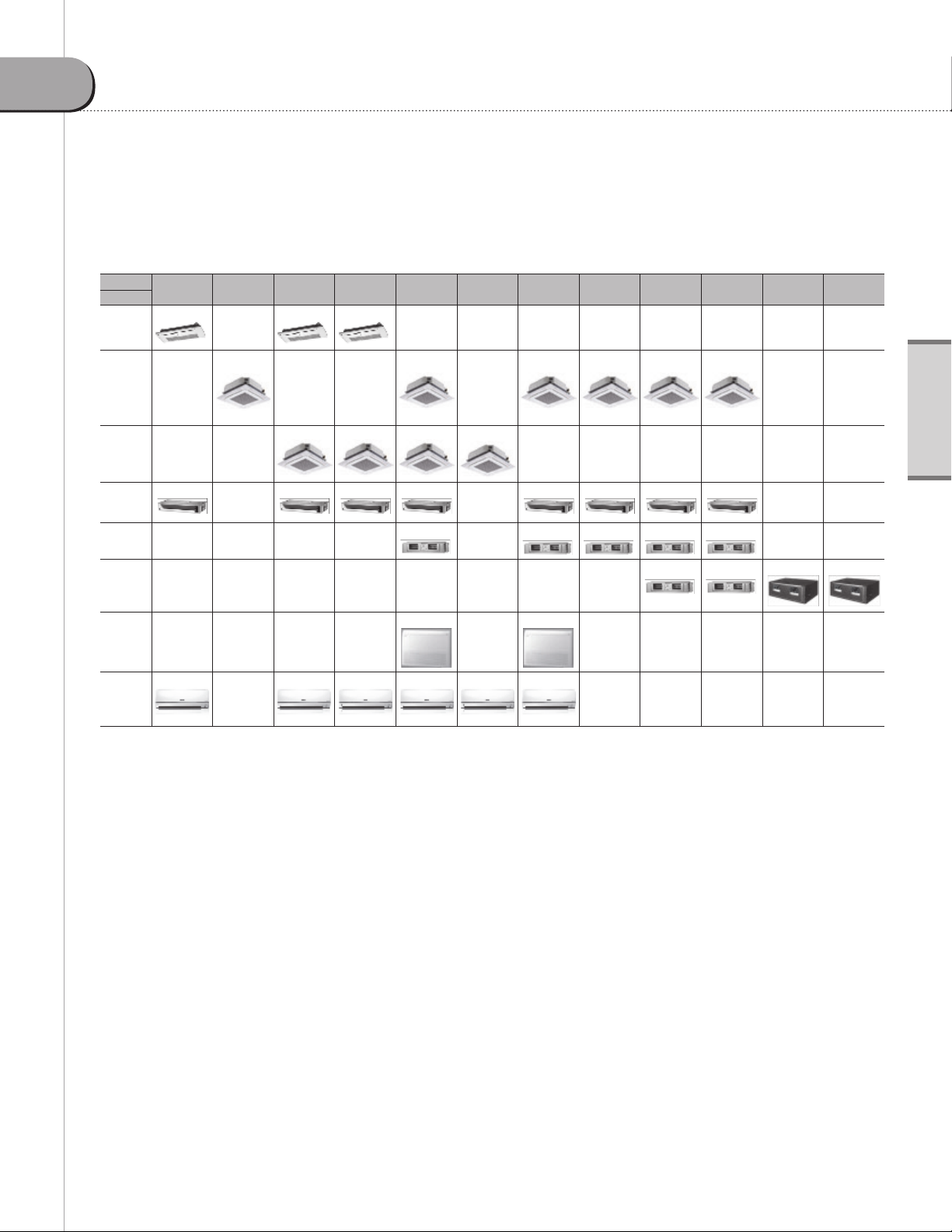
Application Matrix
Capacity
Type
Slim
1 way
cassette
4 way
cassette
Mini 4
way
cassette
Slim
duct
MSP
duct
7.5MBH 9.0MBH 9.5MBH 12MBH 18MBH 20MBH 24MBH 30MBH 36MBH 48MBH 76.8MBH 96MBH
Indoor units
HSP
duct
Ceiling
High Wall
5 VRF-PRC006-EN
Products
Products
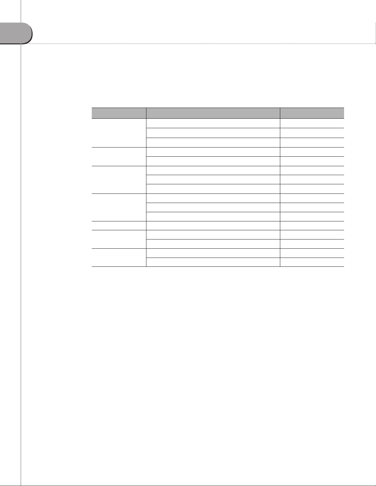
Controls
Family Description Trane Model Number
VRF System Controller TVCTRLTIMD00A0
Integrated System
Management
Building Management
System Gateways
Centralized Control
Systems
Zone Controllers
Interface Modules VRF External Contact Interface Module TVCTRLTIMB14A0
Sensors
Commissioning and
Utility Kits
VRF Enterprise Management Software TVCTRLTSTP3P00
VRF Power Meter Interface Module TVCTRLTIMB16A0
VRF System Controller+BACnet TVCTRLTIMB17A0
VRF System Controller+LONTalk TVCTRLTIMB18A0
VRF Central On/Off Controller TVCTRLTCMA202D
VRF System TouchScreen Control TVCTRLTCMA300T
VRF Mode Select Switch TVCTRLTCMC2000
VRF Wireless Remote Control TVCTRLTRDH00UT
VRF Wired Remote Control TVCTRLTWRWE10T
VRF Duct Signal Receiver & Wire TVCTRLTRKA10N0
VRF Ext. Room Temp Sensor TVCTRLTRWTA000
VRF Motion Sensor Mini 4Way MOTIONSEN4TVB
VRF Auto-Commissioning Tool TVCTRLTIMC1000
VRF Technician Utilities TVCTRLTIMC0300
6 VRF-PRC006-EN
Products
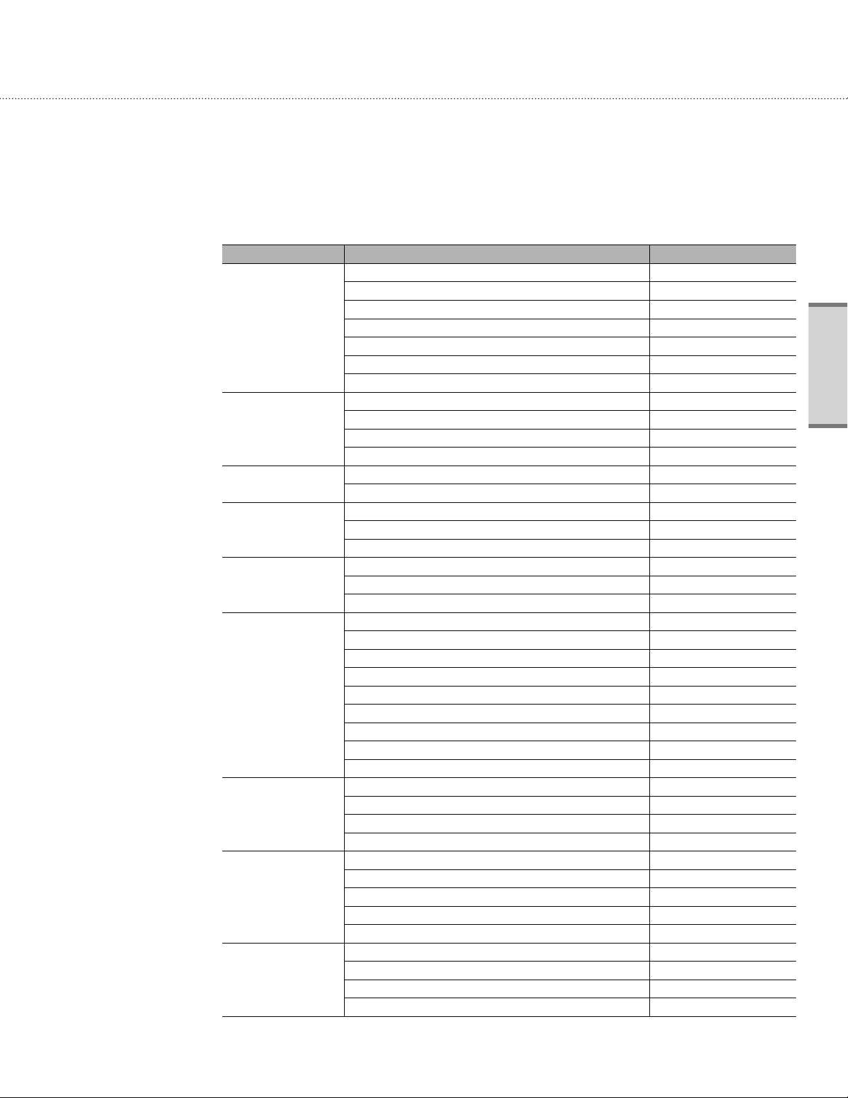
Accessories
Family Description Trane Model Number
VRF Y-joint <51MBh 4YDK1509B0051A
VRF Y-joint 51-138MBh 4YDK2512B0138A
VRF Y-joint 138-160MBh 4YDK2812B0160A
Y- joint
Y-joint
(High Pressure Gas for
HR)
Outdoor T Joint
(Outdoor Connection)
Header Joint
MCU-KIT
EEV Kits
(For Wall-mounted &
Ceiling indoor unit
AHU Kit
DRAIN PUMP
CASSETTE PANEL
VRF Y-joint 160-240MBh 4YDK2815B0240A
VRF Y-joint 240-336MBh 4YDK3419B0336A
VRF Y-joint 336-468MBh 4YDK4119B0468A
VRF Y-joint >468MBh 4YDK4422B0999A
VRF Y-joint HR ≤80MBh 4YDK1500B0080A
VRF Y-joint HR 80-240MBh 4YDK2500B0240A
VRF Y-joint HR 240-468MBh 4YDK3100B0468A
VRF Y-joint HR >468MBh 4YDK3800B0999A
VRF T-joint≤468MBh 4TDK3819B0000A
VRF T-joint HR≤468MBh 4TDK3100B0000A
VRF Header Joint 4Units <160MBh 4HJK2512B0159A
VRF Header Joint 8Units ≤240MBh 4HJK3115B0241A
VRF Header Joint 8Units >240MBh 4HJK3819B0998A
VRF MCU Kit up to 6 IDU 4MCUCUY6NCE000
VRF MCU Kit up to 4 IDU 4MCUCUY4NCE000
VRF MCU Kit 2 IDU HSP Only 4MCUCUY2NCE000
VRF EEV 1x 7-15.5& 1x 17-31MBh 4EEVXDA24K132A
VRF EEV Kit 2Unit 7-15.5MBh 4EEVXDA24K200A
VRF EEV Kit 2Unit 17-31MBh 4EEVXDA32K200A
VRF EEV 2x 7-15.5& 1x 17-31MBh 4EEVXDA24K232A
VRF EEV Kit 3Unit 7-15.5MBh 4EEVXDA24K300A
VRF EEV 1x 7-15.5& 2x 17-31MBh 4EEVXDA32K224A
VRF EEV Kit 3Unit 17-31MBh 4EEVXDA32K300A
VRF EEV Kit 1Unit 7-15.5MBh 4EEVEVA24SA000
VRF EEV Kit 1Unit 17-31MBh 4EEVEVA32SA000
VRF AHU Kit 24-30MBh 4EEVAKA40K1025
VRF AHU Kit 48-60MBh 4EEVAKA40K1050
VRF AHU Kit 72-90MBh 4EEVAKA64K1075
VRF AHU Kit 96-112MBh 4EEVAKA64K1100
VRF Drain Pump Slim Duct CONDPUMPXVLB01
VRF Drain Pump MSP 18/24MBh CONDPUMPXVMB01
VRF Drain Pump MSP 30/36MBh CONDPUMPXVMB02
VRF Drain Pump MSP48/ HSP36-48MBh CONDPUMPXVDB01
VRF Drain Pump HSP 76.8/96MBh CONDPUMPXVHB01
VRF Cassette Panel Slim 1Way TVEPANPC1NUSET
VRF Cassette Panel Sliding 1Way TVEPANPC1NUAET
VRF Cassette Panel Mini 4Way TVEPANPC4SUSET
VRF Cassette Panel 4Way TVEPANPC4NUSET
Indoor units
VRF-PRC006-EN
7
1
Slim 1 way cassette
1-1. Specifications
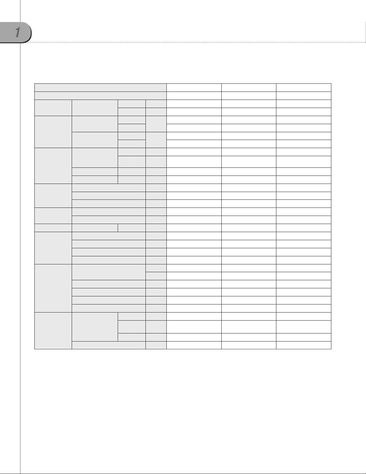
Technical specifications
Model Name 4TVE0007B100NB 4TVE0009B100NB 4TVE0012B100NB
Power Supply 208~230/60/1 208~230/60/1 208~230/60/1
Performance
Power
Fan
Piping Connections
Refrigerant
2
Sound
External Dimensions
Cassette Panel3
Additional Features
Capacity
1
(Nominal)
Power Input
1
(Nominal)
Current Input
1
(Nominal)
Motor
Airflow Rate H/M/L CFM 245/210/175 245/210/175 280/245/210
External Static Pressure Min/Std/Max in. WG - - -
Liquid Pipe Ø inch 1/4 1/4 1/4
Gas Pipe Ø inch 1/2 1/2 1/2
Drain Pipe Ø inch VP 20 (OD 1", ID 3/4") VP 20 (OD 1", ID 3/4") VP 20 (OD 1", ID 3/4")
Type - R410A R410A R410A
Control Method - EEV (Included) EEV (Included) EEV (Included)
Sound Pressure H/M/L dB(A) 27.0/25.0/23.0 29.0/27.0/24.0 35.0/31.0/27.0
Net Weight lbs. 23.15 23.15 23.15
Shipping Weight lbs. 29.75 29.75 29.75
Net Dimensions (Wxhxd) inches 38 1/4 x 5 3/8 x 16 1/8 38 1/4 x 5 3/8 x 16 1/8 38 1/4 x 5 3/8 x 16 1/8
Shipping Dimensions (Wxhxd) inches 43 7/8 x 8 3/8 x 15 13/16 43 7/8 x 8 3/8 x 15 13/16 43 7/8 x 8 3/8 x 15 13/16
Model Name
Net Weight lbs. 6.61 6.61 6.61
Shipping Weight lbs. 11.0 11.0 11.0
Net Dimensions (Wxhxd) inches 46 1/2 x 1.0 x 18 1/8 46 1/2 x 1.0 x 18 1/8 46 1/2 x 1.0 x 18 1/8
Shipping Dimensions (Wxhxd) inches 49 5/8 x 5 11/16 x 21.25 49 5/8 x 5 11/16 x 21.25 49 5/8 x 5 11/16 x 21.25
Drain Pump
Air Filter - Washable Filter Washable Filter Washable Filter
Cooling Btu/h 7,500 9,500 12,000
Heating Btu/h 8,500 10,500 13,500
Cooling
Heating 40.0 45.0 50.0
Cooling
Heating 0.23 0.25 0.28
Type (Qty.) - Crossflow Fan Crossflow Fan Crossflow Fan
Output (Each) W 20 x 1 20 x 1 20 x 1
Model Name - Built-in Built-in Built-in
Max. Lifting
Height
Displacement Gal/Hr. 6.25 6.25 6.25
W
A
- TVEPANPC1NUSET TVEPANPC1NUSET TVEPANPC1NUSET
- TVEPANPC1NUAET TVEPANPC1NUAET TVEPANPC1NUAET
inches 29.5 29.5 29.5
40.0 45.0 50.0
0.23 0.25 0.28
1. Nominal capacity based on 25 ft. of equivalent refrigerant piping with 0 ft. level difference.
- Cooling: Indoor temperature 80°F DB, 67°F WB/Outdoor temperature 95°F DB, 75°F WB
- Heating: Indoor temperature 70°F DB, 60°F WB/Outdoor temperature 47°F DB, 43°F WB
2. Sound pressure was acquired in a dead room. Actual noise level may be different depending on installation conditions.
3. Cassette panel must be ordered separately
4. Trane has a policy of continuous product and product data improvement and reserves the right to change design and specifications without notice.
8 VRF-PRC006-EN
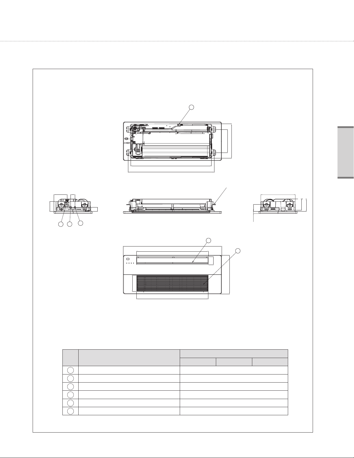
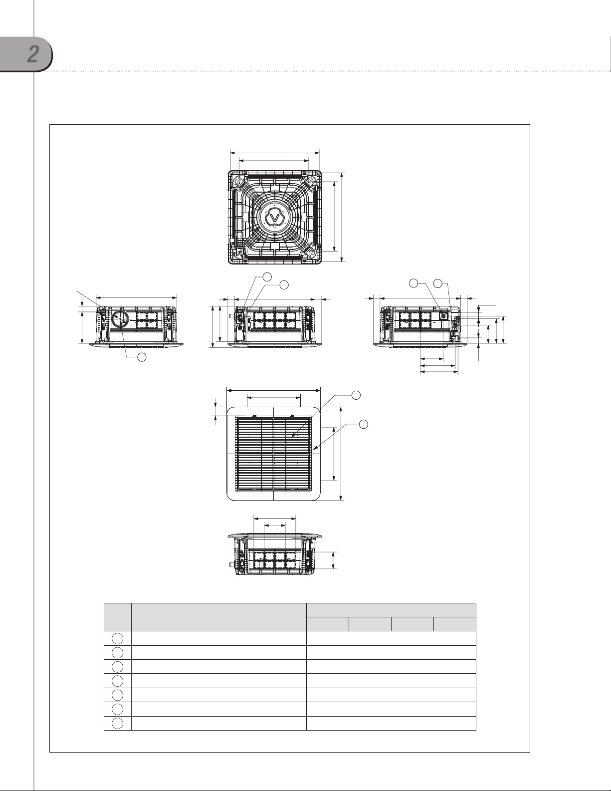
1-2. Dimensional drawing
160(6-1/4) 50(1-15/16)
119(4-5/8)
1
2
3
52(2-1/16)
970(38-1/4)
1036(40-3/4)
Unit: mm(inch)
4
Indoor units
280(11)
410(16-1/8)
Suspension bolts(M8~M10) X 4EA
415(16-3/8)
135(5-3/8)
85(3-3/8)25(1)
150(5-7/8)
1180(46-1/2)
863(34)
197(7-3/4)
861(33-7/8)
No. Name
Liquid pipe connection Ø6.35(1/4") Flare
1
Gas pipe connection Ø12.70(1/2") Flare
2
Drain pipe connection VP20 (OD 26, ID 20) / VP20 (OD 1", ID 3/4")
3
Conduit for power supply & communication wiring
4
Air inlet grille
5
Air outlet louver
6
7.5 MBH 9.5 MBH 12.0 MBH
6
5
94(3-3/4)
460(18-1/8)
Description
-
-
-
VRF-PRC006-EN
9
1
Slim 1 way cassette
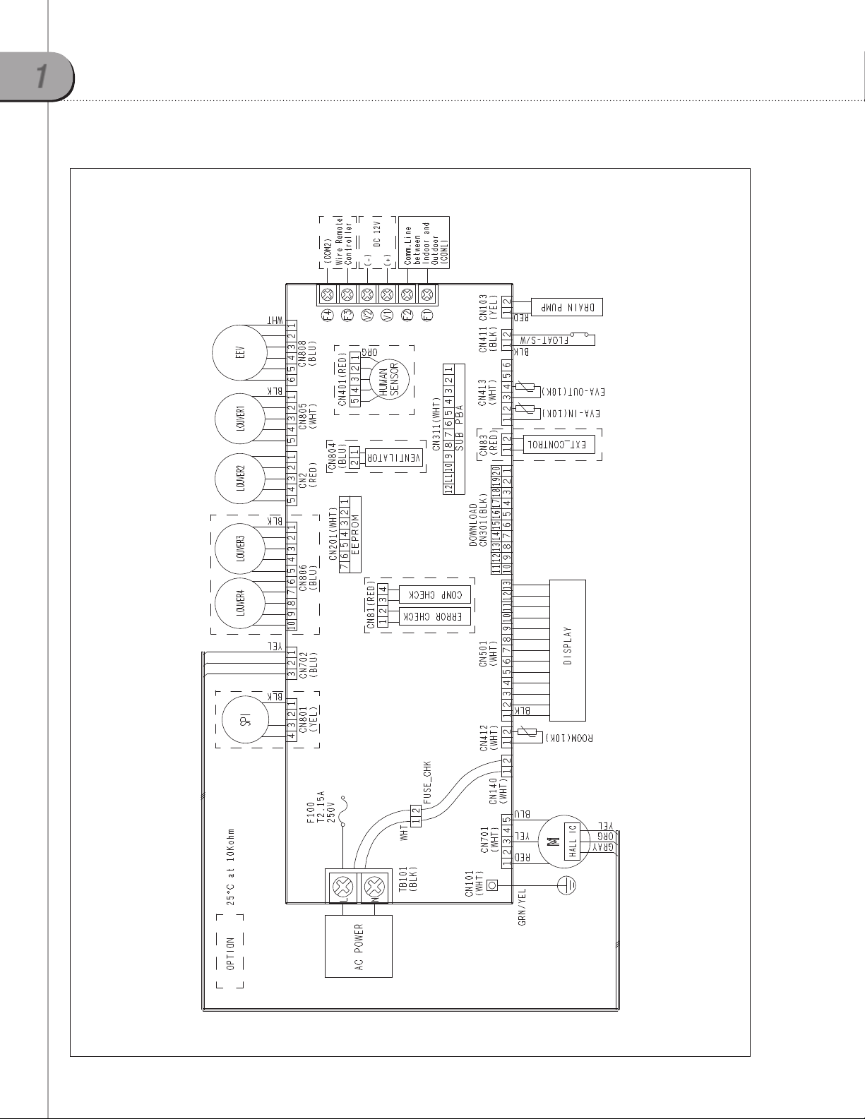
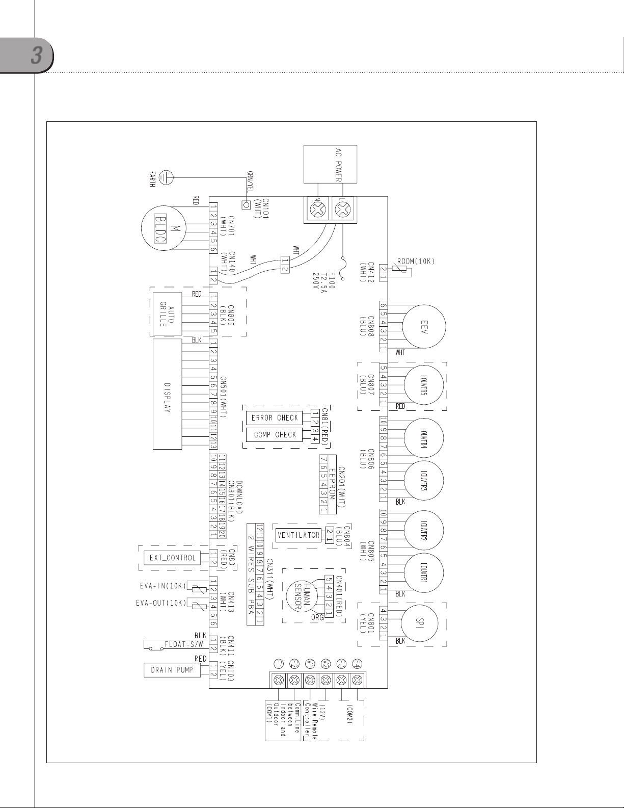
1-3. Electrical wiring diagram
10 VRF-PRC006-EN
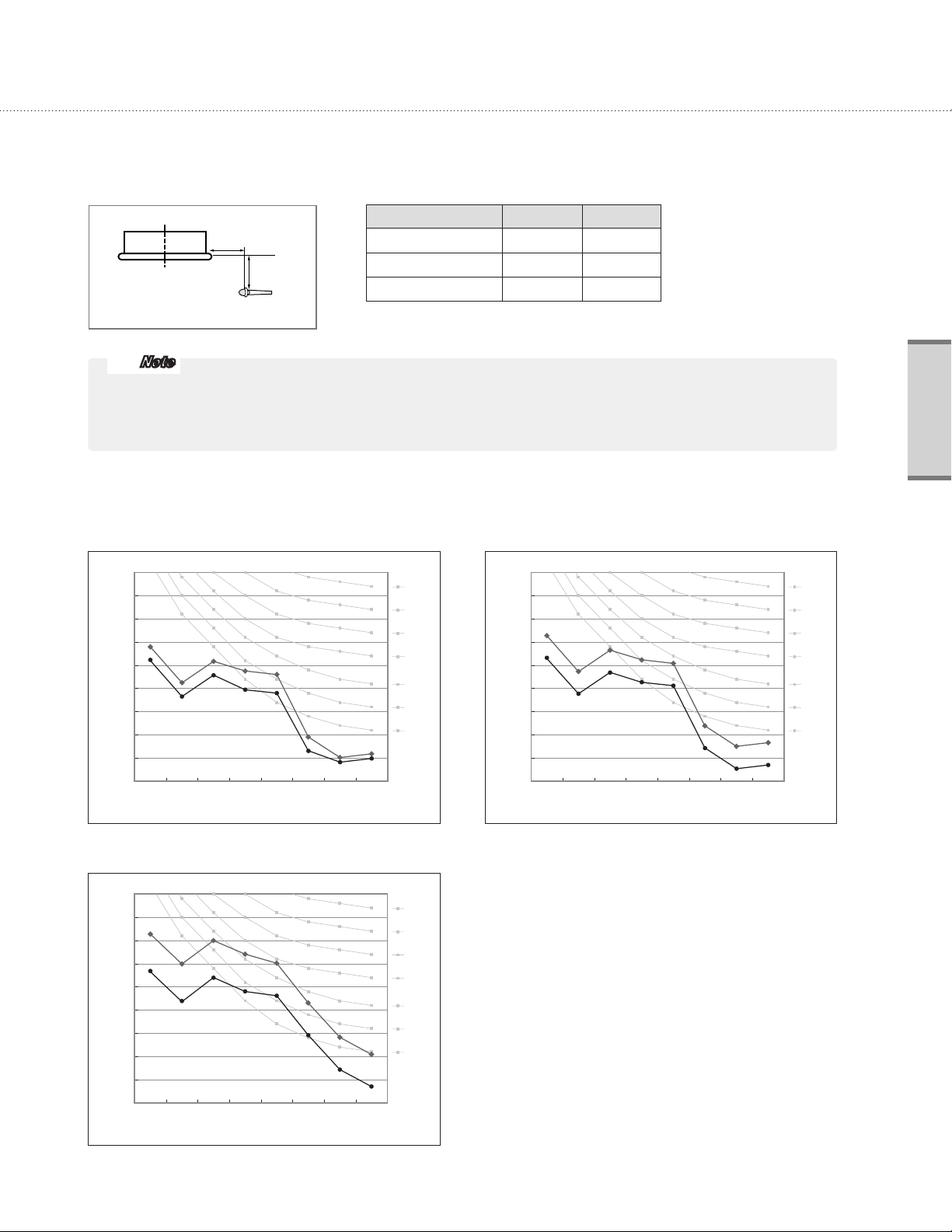
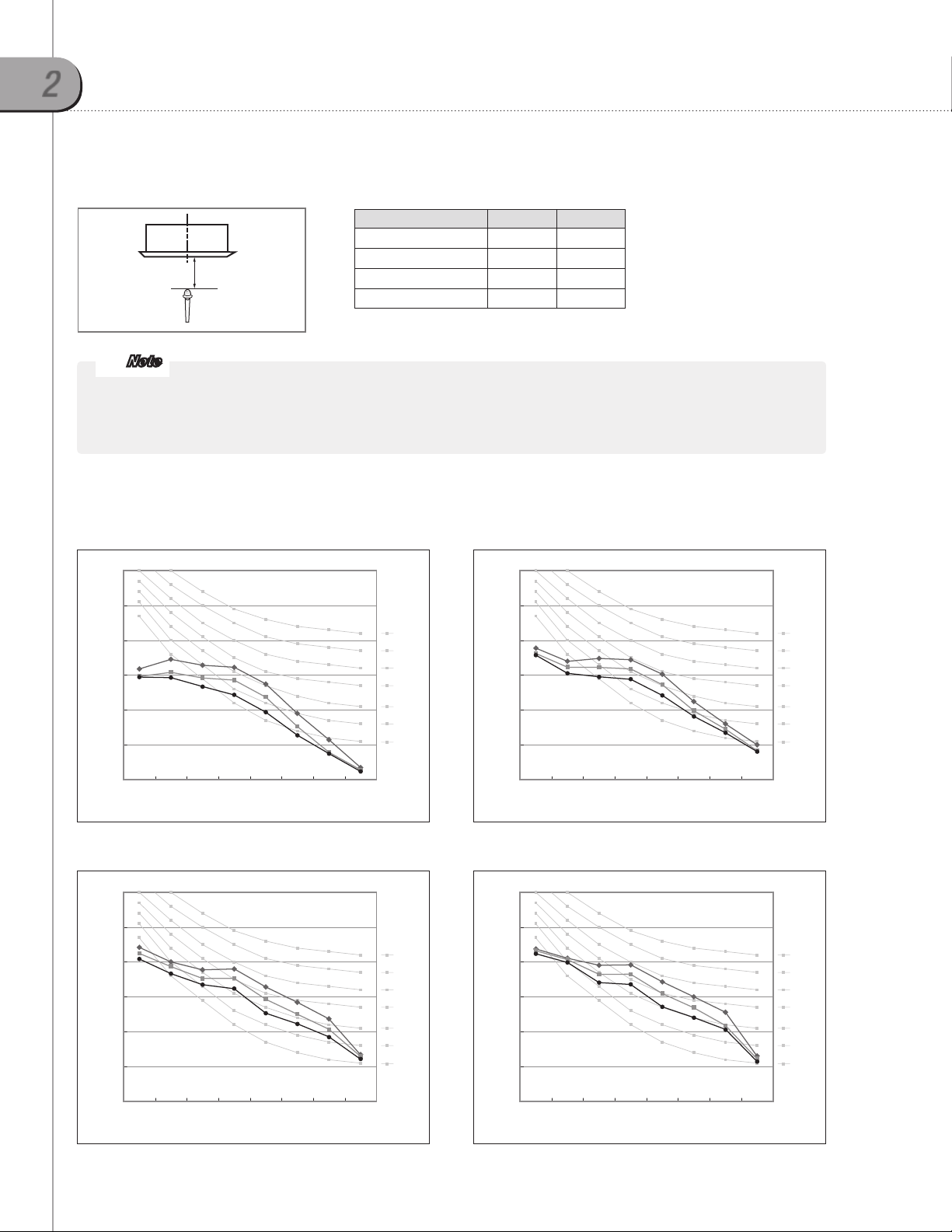
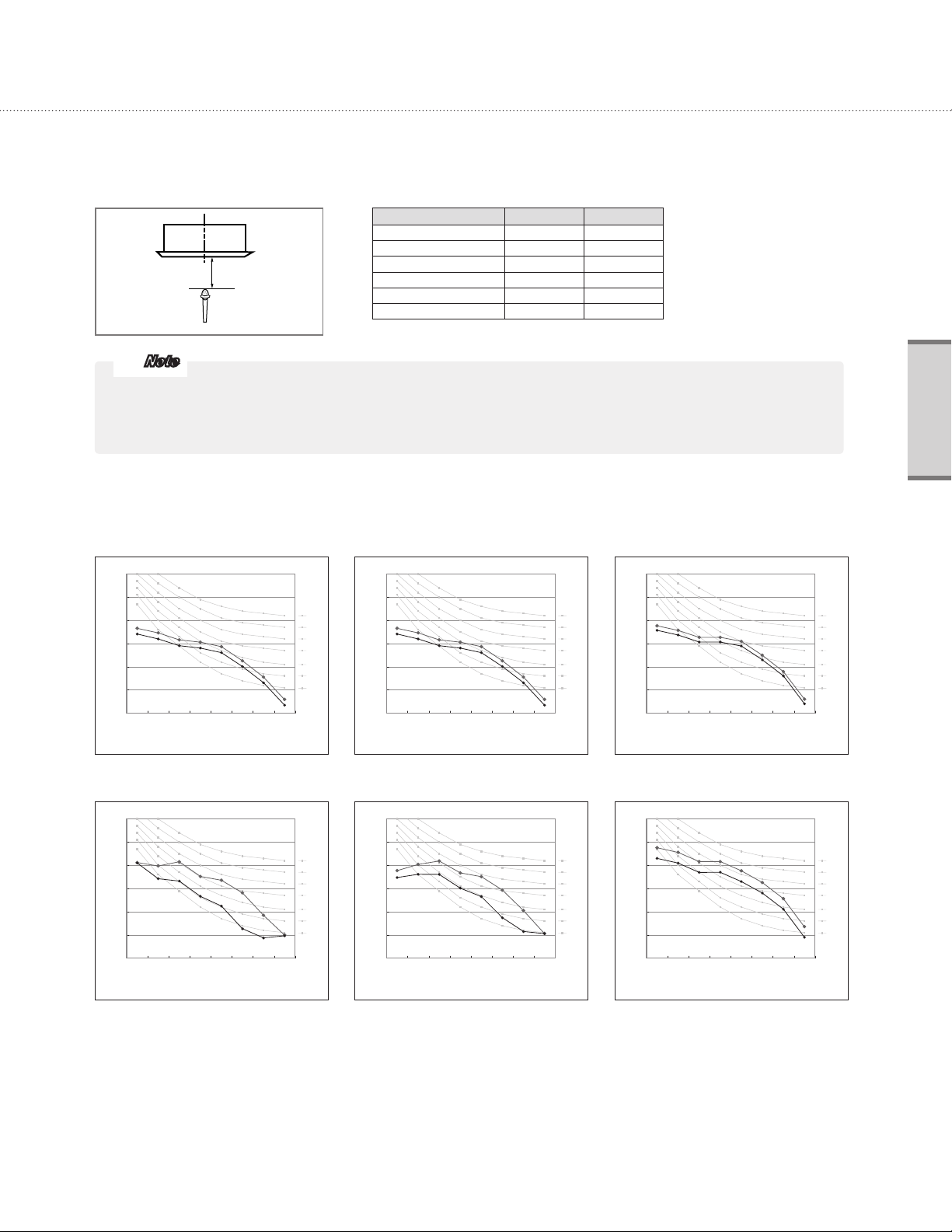
1-4. Sound pressure level
Operation sound level
Unit : dB(A)
Model High Low
1m
1m
4TVE0007B100NB
4TVE0009B100NB
4TVE0012B100NB
27 23
29 24
35 27
Microphone
Note
These operation values were obtained in an anechoic room. Sound pressure level will vary depending on a range of
factors such as the construction of the particular room where the equipment is installed.
Operation sound level may differ depending on operation and ambient conditions.
2) NC curves
(1) 4TVE0007B100NB (2) 4TVE0009B100NB
45
40
35
HIGH
30
25
LOW
20
15
10
Sound pressure level (dB)
5
0
63 1 25 25 0 5 00 100 0 200 0 4000 8000
Octave band center frequency(Hz)
NC 45
NC 40
NC 35
NC 30
NC 25
NC 20
NC 15
45
40
35
HIGH
30
25
LOW
20
15
10
Sound pressure level (dB)
5
0
63 1 25 25 0 5 00 100 0 200 0 4000 8000
Octave band center frequency(Hz)
Indoor units
NC 45
NC 40
NC 35
NC 30
NC 25
NC 20
NC 15
(3) 4TVE0012B100NB
45
40
HIGH
35
30
LOW
25
20
15
10
Sound pressure level (dB)
5
0
63 1 25 25 0 50 0 1 000 200 0 4 000 80 00
Octave band center frequency(Hz)
VRF-PRC006-EN
NC 45
NC 40
NC 35
NC 30
NC 25
NC 20
NC 15
11
1
Slim 1 way cassette
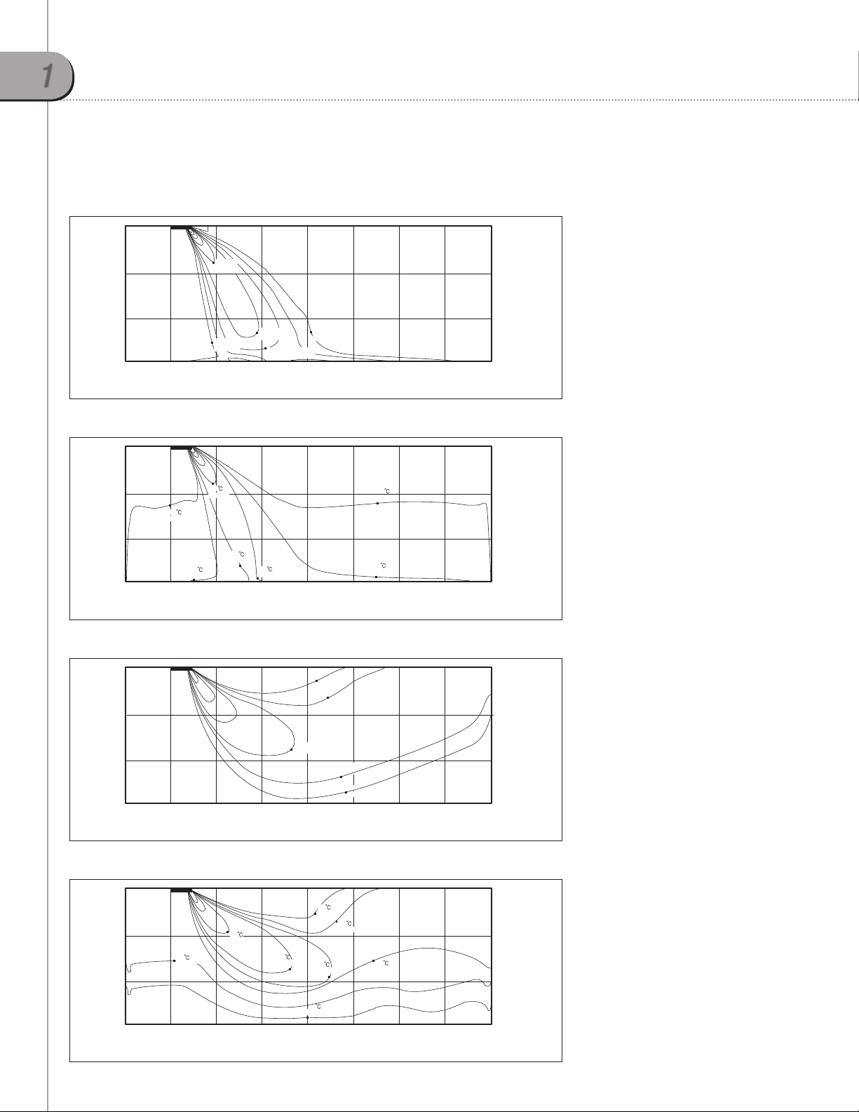
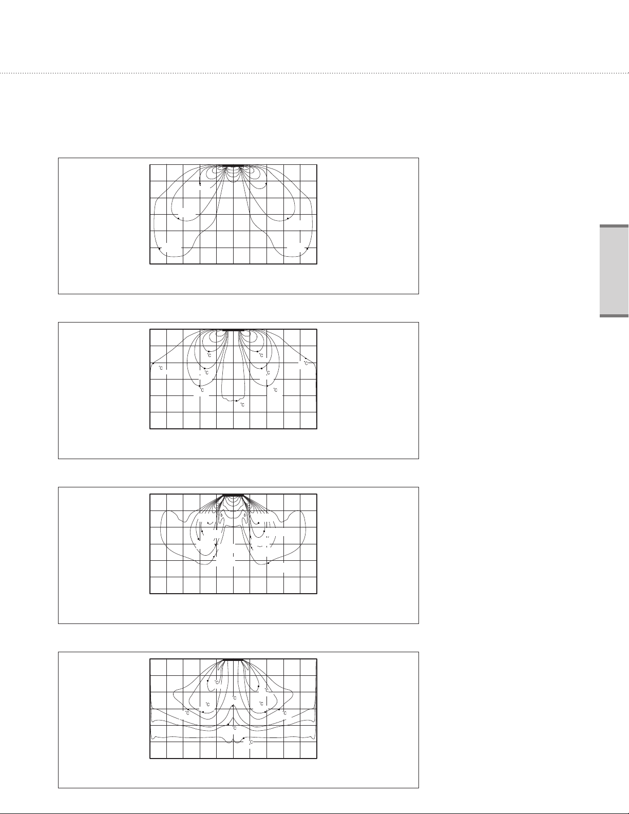
1-5. Temperature and air flow distribution
4TVE0007-0012B100NB
(1)
Cooling air velocity distribution
1.0m/s
(3.28ft/s)
Discharge angle : 60°
3 m
(9.8 ft)
2
m
(6.6 ft)
Ceiling height
0 m
1 m 3 m 4 m
(3.3 ft) (9.8 ft) (13.1 ft)
0.2m/s
(0.66ft/s)
2 m
(6.6 ft)
0.8m/s
(2.62ft/s)
0.6m/s
(1.97ft/s)
Floor distance
0.6m/s
(1.97ft/s)
0.2m/s
(0.66ft/s)
2) Cooling temperature distribution
22
(71.6°F)
25
(77.0°F)
Ceiling height
0 m
1 m 3 m 4 m
(3.3 ft) (9.8 ft) (13.1 ft)
(75.2°F)
23
(73.4°F)
24
2 m
(6.6 ft)
23
(73.4°F)
Floor distance
3) Heating air velocity distribution
0.6m/s
(1.97ft/s)
Ceiling height
0 m
1 m 3 m 4 m
(3.3 ft) (9.8 ft) (13.1 ft)
2 m
(6.6 ft)
Floor distance
0.2m/s
(0.66ft/s)
(1.31ft/s)
0.4m/s
5 m
(16.4 ft)
5 m
(16.4 ft)
0.4m/s
(1.31ft/s)
0.2m/s
(0.66ft/s)
5 m
(16.4 ft)
25
(77.0°F)
24
(75.2°F)
6
m
(19.7 ft)
6
m
(19.7 ft)
6
m
(19.7 ft)
1 m
(3.3 ft)
7 m
(23.0 ft)
8 m
(26.2 ft)(0 ft)
Discharge angle : 60°
3 m
(9.8 ft)
2
m
(6.6 ft)
1 m
(3.3 ft)
7 m
(23.0 ft)
8 m
(26.2 ft)(0 ft)
Discharge angle : 60°
3 m
(9.8 ft)
2
m
(6.6 ft)
1 m
(3.3 ft)
7 m
(23.0 ft)
8 m
(26.2 ft)(0 ft)
4) Heating temperature distribution
33
(91.4°F)
31
(87.8°F)
21
(69.8°F)
Ceiling height
0 m
1 m 3 m 4 m
(3.3 ft) (9.8 ft) (13.1 ft)
23
(73.4°F)
2 m
(6.6 ft)
23
(73.4°F)
27
(80.6°F)
25
(77.0°F)
5 m
(16.4 ft)
25
(77.0°F)
6
m
(19.7 ft)
Discharge angle : 60°
3 m
(9.8 ft)
2
m
(6.6 ft)
1 m
(3.3 ft)
7 m
(23.0 ft)
8 m
(26.2 ft)(0 ft)
Floor distance
12 VRF-PRC006-EN
1
2
Mini 4 way cassette
2-1. Specifications
Technical specifications
Model Name 4TVB0009B100NB 4TVB0012B100NB 4TVB0018B100NB 4TVB0020B100NB
Power Supply 208~230/60/1 208~230/60/1 208~230/60/1 208~230/60/1
Performance
Power
Fan
Piping
Connections
Refrigerant
2
Sound
External
Dimensions
Cassette Panel3
Additional
Features
Capacity
(Nominal)
Power Input
(Nominal)
Current Input
(Nominal)
Motor
Airflow Rate H/M/L Cfm 350/300/265 370/335/280 460/390/335 475/425/360
External Static
Pressure
Liquid Pipe Ø inch 1/4 1/4 1/4 1/4
Gas Pipe Ø inch 1/2 1/2 1/2 1/2
Drain Pipe Ø inch VP 25 (OD 1 1/4", ID 1") VP 25 (OD 1 1/4", ID 1") VP 25 (OD 1 1/4", ID 1") VP 25 (OD 1 1/4", ID 1")
Type - R410A R410A R410A R410A
Control Method - EEV (Included) EEV (Included) EEV (Included) EEV (Included)
Sound Pressure H/M/L Db(A) 34.0/30.0/26.0 36.0/34.0/31.0 40.0/37.0/34.0 41.0/38.0/35.0
Net Weight lbs. 26.5 26.5 26.5 26.5
Shipping Weight lbs. 30.9 30.9 30.9 30.9
Net Dimensions (WxHxD) inches 22 3/4 x 9 3/4 22 3/4 22 3/4 x 9 3/4 22 3/4 22 3/4 x 9 3/4 22 3/4 22 3/4 x 9 3/4 22 3/4
Shipping Dimensions (WxHxD) inches 24 1/2 x 11 3/4 x 22 3/4 24 1/2 x 11 3/4 x 22 3/4 24 1/2 x 11 3/4 x 22 3/4 24 1/2 x 11 3/4 x 22 3/4
Model Name - TVEPANPC4SUSET TVEPANPC4SUSET TVEPANPC4SUSET TVEPANPC4SUSET
Net Weight lbs. 6 6 6 6
Shipping Weight lbs. 9.25 9.25 9.25 9.25
Net Dimensions (WxHxD) inches 26 3/8 X 1 3/4 X 26 3/8 26 3/8 X 1 3/4 X 26 3/8 26 3/8 X 1 3/4 X 26 3/8 26 3/8 X 1 3/4 X 26 3/8
Shipping Dimensions (WxHxD) inches 28 1/8 X 4 3/16 X 28 1/2 28 1/8 X 4 3/16 X 28 1/2 28 1/8 X 4 3/16 X 28 1/2 28 1/8 X 4 3/16 X 28 1/2
Drain Pump
Air Filter - Washable Filter Washable Filter Washable Filter Washable Filter
Motion Sensor
Cooling Btu/h 9,500 12,000 18,000 20,000
1
Heating Btu/h 10,500 13,500 20,000 23,000
Cooling
1
Heating 24.0 28.0 36.0 38.0
Cooling
1
Heating 0.17 0.19 0.27 0.30
Type (Qty.) - Turbo Fan Turbo Fan Turbo Fan Turbo Fan
Output (Each) W 65 x 1 65 x 1 65 x 1 65 x 1
Min/Std/Max In. WG - - - -
Model Name - Built-in Built-in Built-in Built-in
Max. Lifting Height inches 29.5 29.5 29.5 29.5
Displacement Gal/Hr. 6.25 6.25 6.25 6.25
4
W
A
- MOTIONSEN4TVB MOTIONSEN4TVB MOTIONSEN4TVB MOTIONSEN4TVB
24.0 28.0 36.0 38.0
0.17 0.19 0.27 0.30
Indoor units
1. Nominal capacity based on 25 ft. of equivalent refrigerant piping with 0 ft. level difference.
- Cooling: Indoor temperature 80°F DB, 67°F WB/Outdoor temperature 95°F DB, 75°F WB
- Heating: Indoor temperature 70°F DB, 60°F WB/Outdoor temperature 47°F DB, 43°F WB
2. Sound pressure was acquired in a dead room. Actual noise level may be different depending on installation conditions.
3. Cassette panel must be ordered separately
4. Motion sensor must be ordered separately
5. Trane has a policy of continuous product and product data improvement and reserves the right to change design and specifications without notice.
13 VRF-PRC006-EN
41(1.6)
2
Mini 4 way cassette
2-2. Dimensional drawing
585-630(23-24.8) Ceiling opening
500(19.7) Suspension position
500(19.7) Suspension position
585-630(23-24.8) Ceiling opening
Unit: mm(inch)
Ø100(3.9")
225(8.9)
575(22.6)
1
2
47.5(1.9) 47.5(1.9)
47.5(1.9)
250(9.8)
295(11.6)
7
670(26.4)
381(15)
57(2.2)
300(11.8)
150(5.9)
47.5(1.9)575(22.6)
381(15)
120(4.7)
5
6
670(26.4)
3
575(22.6)
165(6.5)
249(9.8)
4
269(10.6)
43(1.7)
40(1.6)
131(5.2)
195(7.7)
176(6.9)
No. Name
Liquid pipe connection Ø6.35(1/4") Flare
1
Gas pipe connection Ø12.70(1/2") Flare
2
Drain pipe connection VP25 (OD 32, ID 25)/VP25 (OD 1 1/4", ID 1")
3
Conduit for power supply & communication wiring
4
Air inlet grille
5
Air outlet louver
6
Fresh air intake Ø100(3.9")
7
9.5 MBH 12.0 MBH 18.0 MBH 20.0 MBH
Description
-
-
-
14 VRF-PRC006-EN

2-3. Electrical wiring diagram
Indoor units
VRF-PRC006-EN
15
2
Mini 4 way cassette
2-4. Sound pressure level
Operation sound level
Unit : dB(A)
Model High Low
Note
1.5m
Microphone
4TVB0009B100NB
4TVB0012B100NB
4TVB0018B100NB
4TVB0020B100NB
34 26
36 31
40 34
41 35
These operation values were obtained in an anechoic room. Sound pressure level will vary depending on a range of
factors such as the construction of the particular room where the equipment is installed.
Operation sound level may differ depending on operation and ambient conditions.
2) NC curves
(1) 4TVB0009B100NB (2) 4TVB0012B100NB
60
50
40
HIGH
Mid
30
LOW
20
Sound pressure level (dB)
10
NC 45
NC 40
NC 35
NC 30
NC 25
NC 20
NC 15
60
50
40
HIGH
Mid
LOW
30
20
Sound pressure level (dB)
10
NC 45
NC 40
NC 35
NC 30
NC 25
NC 20
NC 15
0
63 1 25 25 0 5 00 100 0 200 0 4 000 80 00
Octave band center frequency(Hz)
0
63 1 25 25 0 5 00 100 0 200 0 4 000 80 00
Octave band center frequency(Hz)
(3) 4TVB0018B100NB (4) 4TVB0020B100NB
60
50
HIGH
Mid
40
LOW
30
20
Sound pressure level (dB)
10
0
63 1 25 25 0 5 00 100 0 200 0 4 000 80 00
Octave band center frequency(Hz) Octave band center frequency(Hz)
NC 45
NC 40
NC 35
NC 30
NC 25
NC 20
NC 15
60
50
HIGH
Mid
LOW
40
30
20
Sound pressure level (dB)
10
0
63 1 25 25 0 5 00 100 0 200 0 4 000 80 00
NC 45
NC 40
NC 35
NC 30
NC 25
NC 20
NC 15
16 VRF-PRC006-EN
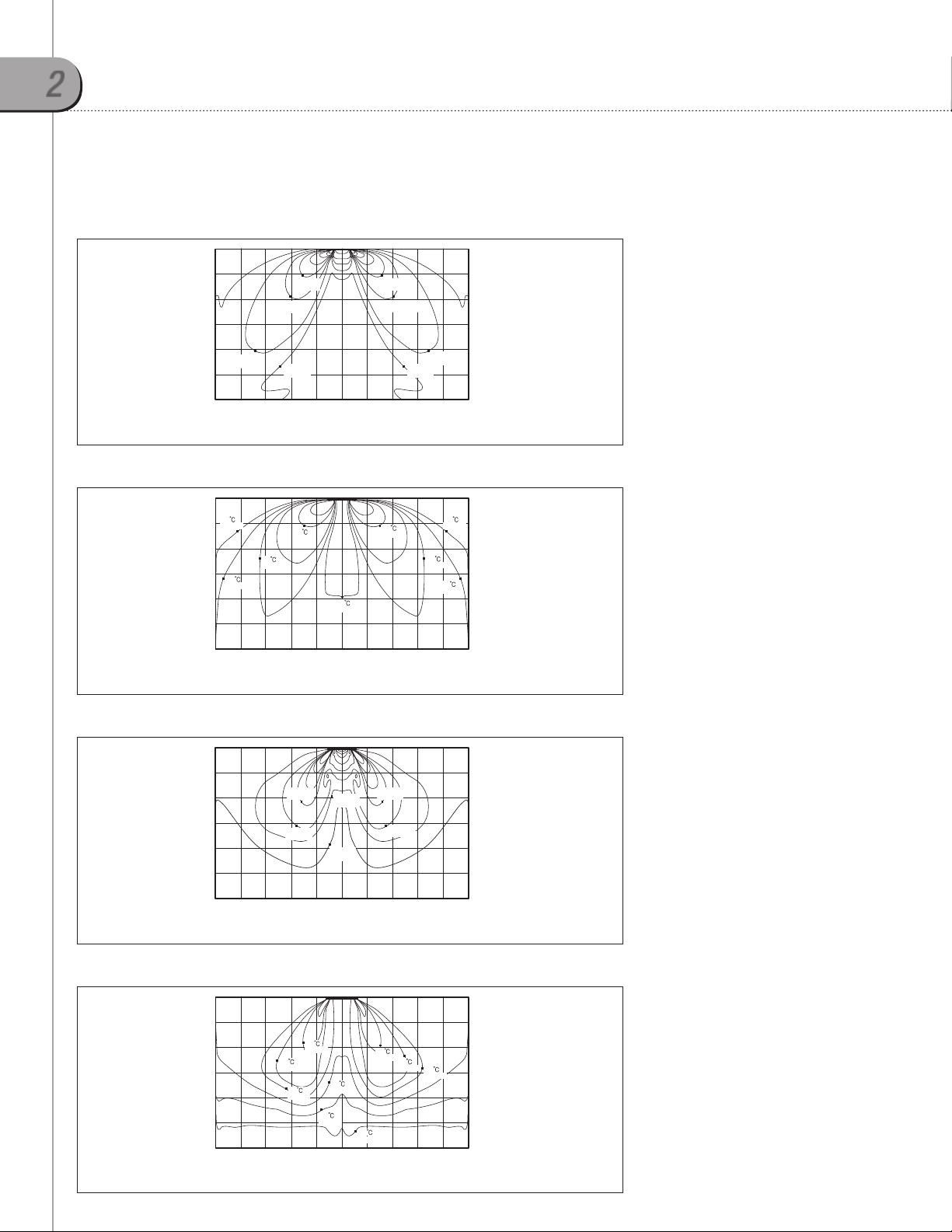
2-5. Temperature and air flow distribution
4TVB0009-0012B100NB
(1) Cooling air velocity distribution
0.6m/s
(1.97ft/s)
0.4m/s
(1.31ft/s)
Ceiling height
0.2m/s
(0.66ft/s)
2.5 m
1.5 m 0 m 1.5m
(2) Cooling temperature distribution
21
24
(75.2°F)
Ceiling height
2.5 m
(69.8°F)
22
(71.6°F)
23
(73.4°F)
1.5 m 0 m 1.5m
(0 ft) (4.9 ft)(4.9 ft) (8.2 ft)(8.2 ft)
Floor distance
24
(75.2°F)
(0 ft) (4.9 ft)(4.9 ft) (8.2 ft)(8.2 ft)
Floor distance
21
(69.8°F)
(71.6°F)
22
0.6m/s
(1.97ft/s)
23
(73.4°F)
0.4m/s
(1.31ft/s)
0.2m/s
(0.66ft/s)
24
(75.2°F)
Discharge angle : 37°
3 m
(9.8 ft)
2 m
(6.6 ft)
1 m
(3.3 ft)
2.5 m
Discharge angle : 37°
3 m
(9.8 ft)
2 m
(6.6 ft)
1 m
(3.3 ft)
2.5 m
Indoor units
(3) Heating air velocity distribution
0.6m/s
(1.97ft/s)
Ceiling height
2.5 m
1.5 m 0 m 1.5m
(4) Heating temperature distribution
27
(80.6°F)
Ceiling height
2.5 m
1.5 m 0 m 1.5m
VRF-PRC006-EN
1.0m/s
(3.28ft/s)
0.8m/s
(2.62ft/s)
0.4m/s
(1.31ft/s)
0.2m/s
(0.66ft/s)
Floor distance
31
(87.8°F)
29
(84.2°F)
Floor distance
(0 ft) (4.9 ft)(4.9 ft) (8.2 ft)(8.2 ft)
25
(77.0°F)
23
(73.4°F)
(0 ft) (4.9 ft)(4.9 ft) (8.2 ft)(8.2 ft)
21
(69.8°F)
1.0m/s
(3.28ft/s)
0.6m/s
(1.97ft/s)
0.4m/s
(1.31ft/s)
31
(87.8°F)
29
(84.2°F)
0.8m/s
(2.62ft/s)
0.2m/s
(0.66ft/s)
27
(80.6°F)
Discharge angle : 49°
3 m
(9.8 ft)
2 m
(6.6 ft)
1 m
(3.3 ft)
2.5 m
Discharge angle : 49°
3 m
(9.8 ft)
2 m
(6.6 ft)
1 m
(3.3 ft)
2.5 m
17
2
Mini 4 way cassette
4TVB0018-0020B100NB
(1) Cooling air velocity distribution
0.8m/s
(2.62ft/s)
0.6m/s
(1.97ft/s)
Ceiling height
0.4m/s
(1.31ft/s)
0.2m/s
(0.66ft/s)
2.5 m
1.5 m 0 m 1.5m
(2) Cooling temperature distribution
25
(77.0°F)
24
(75.2°F)
Ceiling height
2.5 m
20
(68.0°F)
23
(73.4°F)
1.5 m 0 m 1.5m
(0 ft) (4.9 ft)(4.9 ft) (8.2 ft)(8.2 ft)
Floor distance
24
(75.2°F)
(0 ft) (4.9 ft)(4.9 ft) (8.2 ft)(8.2 ft)
Floor distance
0.8m/s
(2.62ft/s)
0.6m/s
(1.97ft/s)
20
(68.0°F)
0.2m/s
(0.66ft/s)
0.4m/s
(1.31ft/s)
23
(73.4°F)
25
(77.0°F)
24
(75.2°F)
Discharge angle : 37°
3 m
(9.8 ft)
2 m
(6.6 ft)
1 m
(3.3 ft)
2.5 m
Discharge angle : 37°
3 m
(9.8 ft)
2 m
(6.6 ft)
1 m
(3.3 ft)
2.5 m
(3) Heating air velocity distribution
Ceiling height
2.5 m
1.5 m 0 m 1.5m
0.8m/s
(2.62ft/s)
0.6m/s
(1.97ft/s)
0.4m/s
(1.31ft/s)
0.2m/s
(0.66ft/s)
(0 ft) (4.9 ft)(4.9 ft) (8.2 ft)(8.2 ft)
0.8m/s
(2.62ft/s)
0.6m/s
(1.97ft/s)
Discharge angle : 49°
3 m
(9.8 ft)
2 m
(6.6 ft)
1 m
(3.3 ft)
2.5 m
Floor distance
(4) Heating temperature distribution
29
(84.2°F)
27
Ceiling height
2.5 m
(80.6°F)
1.5 m 0 m 1.5m
31
(87.8°F)
25
(77.0°F)
23
(73.4°F)
31
(87.8°F)
29
(84.2°F)
27
(80.6°F)
21
(69.8°F)
(0 ft) (4.9 ft)(4.9 ft) (8.2 ft)(8.2 ft)
Discharge angle : 49°
3 m
(9.8 ft)
2 m
(6.6 ft)
1 m
(3.3 ft)
2.5 m
Floor distance
18 VRF-PRC006-EN
1
3
4 way cassette
3-1. Specifications
Technical specifications
Model Name 4TVC0009B100NB 4TVC0018B100NB 4TVC0024B100NB
Power Supply 208~230/60/1 208~230/60/1 208~230/60/1
Performance
Power
Fan
Piping Connections
Refrigerant
2
Sound
External
Dimensions
Cassette Panel3
Additional Features
Capacity
(Nominal)
Power Input
(Nominal)
Current Input
(Nominal)
Motor
Airflow Rate H/M/L Cfm 510/460/390 545/495/425 615/565/495
External Static
Pressure
Liquid Pipe Ø inch 1/4 1/4 1/4
Gas Pipe Ø inch 1/2 1/2 1/2
Drain Pipe Ø inch VP 25 (OD 1 1/4", ID 1") VP 25 (OD 1 1/4", ID 1") VP 25 (OD 1 1/4", ID 1")
Type - R410A R410A R410A
Control Method - EEV (Included) EEV (Included) EEV (Included)
Sound Pressure H/M/L Db(A) 34.0/33.0/31.0 34.0/33.0/31.0 36.0/35.0/34.0
Net Weight lbs. 33.1 33.1 33.1
Shipping Weight lbs. 40.8 40.8 40.8
Net Dimensions (WxHxD) inches 33 x 8 x 33 33 x 8 x 33 33 x 8 x 33
Shipping Dimensions (WxHxD) inches 35 3/8 x 10 7/8 x 35 3/8 35 3/8 x 10 7/8 x 35 3/8 35 3/8 x 10 7/8 x 35 3/8
Model Name - TVEPANPC4NUSET TVEPANPC4NUSET TVEPANPC4NUSET
Net Weight lbs. 12.8 12.8 12.8
Shipping Weight lbs. 18.5 18.5 18.5
Net Dimensions (WxHxD) inches 37 7/16 x 1 3/4 x 37 7/16 37 7/16 x 1 3/4 x 37 7/16 37 7/16 x 1 3/4 x 37 7/16
Shipping Dimensions (WxHxD) inches 39 9/16 x 4 x 39 9/16 39 9/16 x 4 x 39 9/16 39 9/16 x 4 x 39 9/16
Drain Pump
Air Filter - Washable Filter Washable Filter Washable Filter
Cooling Btu/h 9,000 18,000 24,000
1
Heating Btu/h 10,000 20,000 27,000
Cooling
1
Heating 32.0 32.0 40.0
Cooling
1
Heating 0.25 0.25 0.30
Type (Qty.) - Turbo Fan Turbo Fan Turbo Fan
Output (Each) W 65 x 1 65 x 1 65 x 1
Min/Std/Max In. WG - - -
Model Name - Built-in Built-in Built-in
Max. Lifting Height inches 29.5 29.5 29.5
Displacement Gal/Hr. 6.25 6.25 6.25
W
A
32.0 32.0 40.0
0.25 0.25 0.30
Indoor units
1. Nominal capacity based on 25 ft. of equivalent refrigerant piping with 0 ft. level difference.
- Cooling: Indoor temperature 80°F DB, 67°F WB/Outdoor temperature 95°F DB, 75°F WB
- Heating: Indoor temperature 70°F DB, 60°F WB/Outdoor temperature 47°F DB, 43°F WB
2. Sound pressure was acquired in a dead room. Actual noise level may be different depending on installation conditions.
3. Cassette panel must be ordered separately
4. Trane has a policy of continuous product and product data improvement and reserves the right to change design and specifications without notice.
19 VRF-PRC006-EN

3
4 way cassette
Technical specifications
Model Name 4TVC0030B100NB 4TVC0036B100NB 4TVC0048B100NB
Power Supply 208~230/60/1 208~230/60/1 208~230/60/1
Performance
Power
Fan
Piping Connections
Refrigerant
2
Sound
External
Dimensions
Cassette Panel3
Additional Features
Capacity
(Nominal)
Power Input
(Nominal)
Current Input
(Nominal)
Motor
Airflow Rate H/M/L Cfm 775/690/600 845/775/705 1025/950/850
External Static
Pressure
Liquid Pipe Ø inch 3/8 3/8 3/8
Gas Pipe Ø inch 5/8 5/8 5/8
Drain Pipe Ø inch VP 25 (OD 1 1/4", ID 1") VP 25 (OD 1 1/4", ID 1") VP 25 (OD 1 1/4", ID 1")
Type - R410A R410A
Control Method - EEV (Included) EEV (Included) EEV (Included)
Sound Pressure H/M/L Db(A) 39.0/34.0/30.0 40.0/37.0/33.0 44.0/42.0/39.0
Net Weight lbs. 40.8 40.8 40.8
Shipping Weight lbs. 50.7 50.7 50.7
Net Dimensions (WxHxD) inches 33 x 11 1/4 x 33 33 x 11 1/4 x 33 33 x 11 1/4 x 33
Shipping Dimensions (WxHxD) inches 35 3/8 x 14 x 35 3/8 35 3/8 x 14 x 35 3/8 35 3/8 x 14 x 35 3/8
Model Name - TVEPANPC4NUSET TVEPANPC4NUSET TVEPANPC4NUSET
Net Weight lbs. 12.8 12.8 12.8
Shipping Weight lbs. 18.5 18.5 18.5
Net Dimensions (WxHxD) inches 37 7/16 x 1 3/4 x 37 7/16 37 7/16 x 1 3/4 x 37 7/16 37 7/16 x 1 3/4 x 37 7/16
Shipping Dimensions (WxHxD) inches 39 9/16 x 4 x 39 9/16 39 9/16 x 4 x 39 9/16 39 9/16 x 4 x 39 9/16
Drain Pump
Air Filter - Washable Filter Washable Filter Washable Filter
Cooling Btu/h 30,000 36,000 48,000
1
Heating Btu/h 34,000 40,000 54,000
Cooling
1
Heating 65.0 75.0 95.0
Cooling
1
Heating 0.50 0.56 0.75
Type (Qty.) - Turbo Fan Turbo Fan Turbo Fan
Output (Each) W 97 x 1 97 x 1 97 x 1
Min/Std/Max In. WG - - -
Model Name - Built-in Built-in Built-in
Max. Lifting Height inches 29.5 29.5 29.5
Displacement Gal/Hr. 6.25 6.25 6.25
W
A
65.0 75.0 95.0
0.50 0.56 0.75
1. Nominal capacity based on 25 ft. of equivalent refrigerant piping with 0 ft. level difference.
- Cooling: Indoor temperature 80°F DB, 67°F WB/Outdoor temperature 95°F DB, 75°F WB
- Heating: Indoor temperature 70°F DB, 60°F WB/Outdoor temperature 47°F DB, 43°F WB
2. Sound pressure was acquired in a dead room. Actual noise level may be different depending on installation conditions.
3. Cassette panel must be ordered separately
4. Trane has a policy of continuous product and product data improvement and reserves the right to change design and specifications without notice.
20 VRF-PRC006-EN
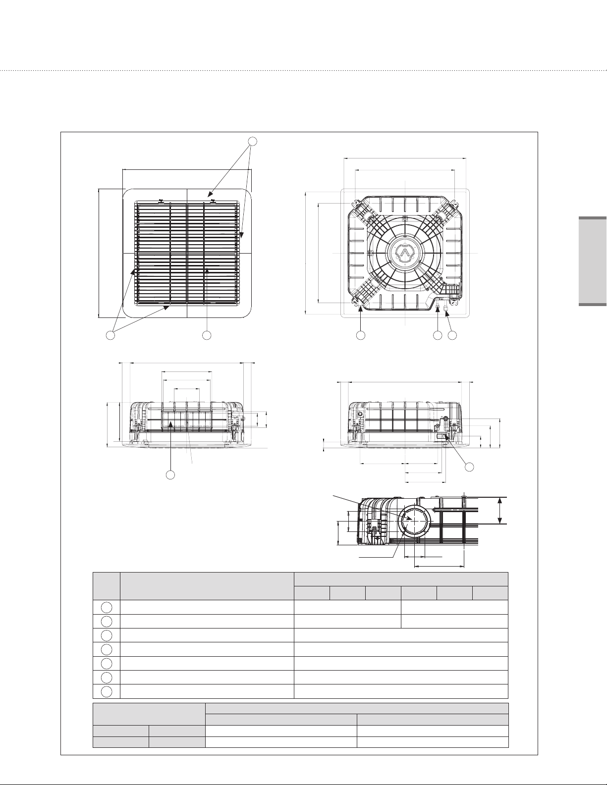
3-2. Dimensional drawing
950(37.4)
950(37.4)
Unit: mm(inch)
6
890~910(35~35.8) Celling opening
735(28.9) Suspension position
Indoor units
735(28.9) Suspension position
890~910(35~35.8) Celling opening
6 5
55(2.2) 840(33.0)
370(14.6)
346(13.6)
185(7.3)
AB
Sub duct connection
7
No. Name
Liquid pipe connection Ø6.35(1/4") Flare Ø9.52(3/8") Flare
1
Gas pipe connection Ø12.70(1/2") Flare Ø15.88(5/8") Flare
2
Drain pipe connection VP25 (OD 32, ID 25)/VP25 (OD 1 1/4", ID 1")
3
Conduit for power supply & communication wiring
4
Air inlet grille
5
Air outlet louver
6
Sub-Duct
7
55(2.2)
96(3.8)
120(4.7)
45(1.8)
Fresh Air Intake
9MBH 18MBH 24MBH 30MBH 36MBH 48MBH
3 2 1
55(2.2) 55(2.2)840(33.1)
330(13)
80(3.1)
92.6(3.6)
4(0.2)-Ø3.3(0.1)
240(9.4)
270(10.6)
300(11.8)
Description
-
-
-
-
80(3.1)
195(7.7)
216(8.5)
164(6.5)
86(3.4)
4
E
A mm(inch) 204(8.0) 288(11.3)
B mm(inch) 253(10.0) 337(13.3)
VRF-PRC006-EN
Description
9/18/24 MBH 30/36/48 MBH
21
3
4 way cassette
3-3. Electrical wiring diagram
22 VRF-PRC006-EN
3-4. Sound pressure level
63 125 25 0 500 1000 200 0 400 0 80 00
63 125 25 0 500 1000 200 0 400 0 80 00
63 125 25 0 500 1000 200 0 400 0 80 00
Operation sound level
Unit: dB(A)
Model High Low
4TVC0009B100NB 34 31
4TVC0018B100NB 34 31
4TVC0024B100NB 36 34
4TVC0030B100NB 39 30
4TVC0036B100NB 40 33
4TVC0048B100NB 44 39
Note
1.5m
Microphone
These operation values were obtained in an anechoic room. Sound pressure level will vary depending on a
range of factors such as the construction of the particular room where the equipment is installed.
Operation sound level may differ depending on operation and ambient conditions.
NC curves
(1) 4TVC0009B100NB
60
50
40
HIGH
LOW
30
20
10
Sound pressure level (dB)
0
Octave band center frequency(Hz)
NC 45
NC 40
NC 35
NC 30
NC 25
NC 20
NC 15
(2) 4TVC0018B100NB
60
50
40
HIGH
LOW
30
20
10
Sound pressure level (dB)
0
Octave band center frequency(Hz)
NC 45
NC 40
NC 35
NC 30
NC 25
NC 20
NC 15
(3) 4TVC0024B100NB
60
50
40
HIGH
LOW
30
20
10
Sound pressure level (dB)
0
Octave band center frequency(Hz)
NC 45
NC 40
NC 35
NC 30
NC 25
NC 20
NC 15
Indoor units
(4) 4TVC0030B100NB
60
50
HIGH
40
LOW
30
20
10
Sound pressure level (dB)
0
63 125 25 0 500 1000 200 0 400 0 80 00
Octave band center frequency(Hz)
VRF-PRC006-EN
NC 45
NC 40
NC 35
NC 30
NC 25
NC 20
NC 15
(5) 4TVC0036B100NB
60
50
HIGH
40
LOW
30
20
10
Sound pressure level (dB)
0
63 125 25 0 500 1000 200 0 400 0 80 00
Octave band center frequency(Hz)
NC 45
NC 40
NC 35
NC 30
NC 25
NC 20
NC 15
(6) 4TVC0048B100NB
60
50
HIGH
LOW
40
30
20
10
Sound pressure level (dB)
0
63 125 25 0 500 1000 200 0 400 0 80 00
Octave band center frequency(Hz)
NC 45
NC 40
NC 35
NC 30
NC 25
NC 20
NC 15
23

3
4 way cassette
3-5. Temperature and air flow distribution
4TVC0009B100NB
(1) Cooling air velocity distribution
0.4m/s
·
(1.31ft/s)
·0.1m/s
(0.33ft/s)
YU\
O_UYP
Y
O]U]P
·0.3m/s
(0.98ft/s)
·0.6m/s
(1.97ft/s)
X
OZUZP
·0.8m/s
(2.62ft/s)
·0.2m/s
(0.66ft/s)
·0.1m/s
(0.33ft/s)
·0.9m/s
(2.95ft/s)
·0.7m/s
(2.30ft/s)
X
OZUZP
·0.5m/s
(1.64ft/s)
Discharge angle :
·0.2m/s
(0.66ft/s)
Y
O]U]P
·0.1m/s
(0.33ft/s)
·0.3m/s
(0.98ft/s)
YU\
O_UYP
YU^
O_U`P
Y
O]U]P
X
OZUZP
(2) Cooling temperature distribution
·23℃
(73.4 ℉)
YU\
O_UYP
·21.5℃
(70.7 ℉)
·20.5℃
(68.9 ℉)
Y
O]U]P
·21℃
(69.8℉)
19.5℃
·
(67.1℉)
X
OZUZP
·18℃
(64.4℉)
17℃
·
(62.6℉)
·22℃
(71.6℉)
·23℃
(73.4℉)
·17.5℃
(63.5℉)
·22℃
(71.6℉)
X
OZUZP
·
18.5℃
(65.3℉)
Discharge angle :
·22℃
(71.6℉)
·21℃
(69.8℉)
·20.5℃
(68.9℉)
Y
O]U]P
YU\
O_UYP
YU^
O_U`P
Y
O]U]P
X
OZUZP
24 VRF-PRC006-EN

4TVC0009B100NB
(3) Heating air velocity distribution
Discharge angle :
YU^
O_U`P
·0.14m/s
(0.46fit/s)
·0.57m/s
(1.87fit/s)
·0.28m/s
(0.92fit/s)
·0.14m/s
(1.31fit/s)
YU\
O_UYP
Y
O]U]P
(4) Heating temperature distribution
28.5℃
·
(83.3℉)
·
29.4℃
(84.9℉)
X
OZUZP
·0.85m/s
(2.79fit/s)
·32.8℃
(91.8℉)
·1.1m/s
(3.61fit/s)
34.5℃
·
(94.1℉)
·0.14m/s
(0.46fit/s)
0.28m/s
·
(0.92fit/s)
·1.3m/s
·35.5℃
(95.9℉)
(4.27fit/s)
·
·0.14m/s
(0.46fit/s)
·33.6℃
(92.5℉)
1m/s
(3.28fit/s)
X
OZUZP
·0.7m/s
(2.30fit/s)
·
0.14m/s
(0.46fit/s)
·0.42m/s
(1.38fit/s)
O]U]P
Discharge angle :
Y
·29.4℃
(84.9℉)
YU\
O_UYP
Y
O]U]P
X
OZUZP
YU^
O_U`P
Y
O]U]P
Indoor units
YU\
O_UYP
Y
O]U]P
VRF-PRC006-EN
·
30℃
(86℉)
·32℃
(89.6℉)
·
31℃
(87.8℉)
X
OZUZP
·30℃
(86℉)
·26.7℃
(80.1℉)
·28.5℃
(83.3℉)
·
29.4℃
(84.9℉)
·27.6℃
(81.7℉)
X
OZUZP
·
32℃
(89.6℉)
Y
O]U]P
·
32℃
(89.6℉)
YU\
O_UYP
X
OZUZP
25

3
4 way cassette
4TVC0018B100NB
(1) Cooling air velocity distribution
·0.5m/s
(1.64fit/s)
·
0.2m/s
(0.66fit/s)
0.6m/s
·
(1.97fit/s)
·0.1m/s
(0.33fit/s)
·
0.9m/s
(2.95fit/s)
·0.2m/s
(0.66fit/s)
0.1m/s
·
0.33fit/s)
·0.3m/s
(0.98fit/s)
·1m/s
(3.98fit/s)
·0.7m/s
(2.30fit/s)
·0.1m/s
(0.33fit/s)
·
0.1m/s
(0.33fit/s)
·
0.3m/s
(0.98fit/s)
·0.2m/s
(0.66fit/s)
YU^
O_U`P
Y
O]U]P
X
OZUZP
YU^\
Y
(2) Cooling temperature distribution
23℃
·
(73.4℉)
·19.5℃
·
21.5℃
(70.7℉)
·
21℃
(69.8℉)
X
(67.1℉)
·18.5℃
(65.3℉)
17.5℃
·
(63.6℉)
·
23℃
(73.4℉)
·
17℃
(62.6℉)
·22℃
(71.6℉)
·18℃
(64.4℉)
X
Y
·
21℃
(69.8℉)
·24℃
(75.2℉)
·22℃
(71.6℉)
YU^\
YU^
O_U`P
Y
O]U]P
X
OZUZP
YU^\
Y
·20.5℃
(68.9℉)
X
X
Y
·20.5℃
(68.9℉)
YU^\
26 VRF-PRC006-EN

4TVC0018B100NB
(3) Heating air velocity distribution
Discharge angle :
YU^\
·
0.14m/s
(0.46fit/s)
·0.14m/s
·0.28m/s
(0.92fit/s)
·0.28m/s
(0.92fit/s)
·0.14m/s
(0.46fit/s)
(0.46fit/s)
·0.57m/s
(1.87fit/s)
Y
·
0.85m/s
(2.79fit/s)
X
·1.1m/s
(3.61fit/s)
·1.6m/s
(5..25fit/s)
·0.14m/s
(0.46fit/s)
·0.42m/s
(1.38fit/s)
·0.28m/s
(0.92fit/s)
1.4m/s
·
(4.59fit/s)
·
(3.28fit/s)
X
1m/s
·0.7m/s
(2.30fit/s)
Y
·0.14m/s
(0.46fit/s)
·
·0.14m/s
(0.46fit/s)
0.14m/s
(0.46fit/s)
·
0.28m/s
(0.92fit/s)
·0.42m/s
(1.38fit/s)
YU^\
YU^
O_U`P
Y
O]U]P
X
OZUZP
Indoor units
(4) Heating temperature distribution
·
35.3℃
(95.5℉)
·36.8℃
(98.2℉)
·38.3℃
(100.9℉)
·39℃
(102.2℉)
·
30.7℃
(86℉)
(87.3℉)
Y
YU^\
·30℃
·39.8℃
(103.6℉)
X
·
34.6℃
(94.3℉)
·31.5℃
(88.7℉)
·
33℃
(91.4℉)
·33.8℃
(92.8℉)
·32.3℃
(90.1℉)
·40.6℃
(105.1℉)
X
·35.3℃
(95.5 ℉)
·39℃
(102.2 ℉)
·
30.7℃
(87.3 ℉)
Discharge angle :
·
36.1℃
(97.0 ℉)
37.6℃
·
(99.7 ℉)
·30℃
(86 ℉)
Y
YU^\
YU^
O_U`P
Y
O]U]P
X
OZUZP
VRF-PRC006-EN
27

3
4 way cassette
4TVC0024B100NB
(1) Cooling air velocity distribution
YU^
O_U`P
·0.1m/s
(0.33fit/s)
·0.2m/s
(0.66fit/s)
Y
ZUX
Z
0.3m/s
·
(0.98fit/s)
(2) Cooling temperature distribution
·0.7m/s
(2.30fit/s)
X
·0.9m/s
(2.95fit/s)
·1m//s
(3.28fit/s)
X
·0.8m/s
(2.62fit/s)
·0.1m/s
(0.33fit/s)
·0.5m/s
(1.64fit/s)
·0.2m/s
(0.66fit/s)
·0.3m/s
(0.98fit/s)
Y Z
Y
O]U]P
X
OZUZP
ZUX
YU^
O_U`P
·24℃
(75.2℉)
·22℃
(71.6℉)
·20℃
(68℉)
Z ZUX
ZUX
Y
21℃
·
(69.8℉)
·18.5℃
(65.3℉)
X
·17.5℃
(63.5℉)
22℃
·
(71.6℉)
·18℃
(64.4℉)
X
·19℃
(66.2℉)
23℃
·
(73.4℉)
·21℃
(69.8℉)
21℃
·
·20℃
(68℉)
Y Z
Y
O]U]P
X
OZUZP
28 VRF-PRC006-EN

4TVC0024B100NB
(3) Heating air velocity distribution
·0.14m/s
(0.46fit/s)
·0.28m/s
(0.92fit/s)
1m/s
·
(3.28fit/s)
·
1.3m/s
(4.27fit/s)
·
0.42m/s
(1.38fit/s)
·0.28m/s
(0.92fit/s)
·0.14m/s
(0.46fit/s)
·1.4m/s
(4.59fit/s)
·0.28m/s
(0.92fit/s)
·1.1m/s
(3.61fit/s)
·0.14m/s
(0.46fit/s)
Discharge angle :
YU^
O_U`P
·0.14m/s
(0.46fit/s)
Y
O]U]P
Indoor units
·0.28m/s
(0.92fit/s)
·0.7m/s
(2.30fit/s)
·0.42m/s
(1.38fit/s)
0.14m/s
·
(0.46fit/s)
ZUX
Z
Y
(4) Heating temperature distribution
·34.5℃
(94.1℉)
·33.7℃
(92.7℉)
·
35.3℃
(95.5℉)
·38.5℃
(101.3℉)
X
40℃
·
(104℉)
·41.5℃
(106.7℉)
·34.5℃
(94.1℉)
33℃
·
(91.4℉)
·33.7℃
(92.7℉)
42℃
·
(107.6℉)
·
·
(94.1℉)
·33℃
(91.4℉)
40.8℃
(105.4℉)
34.5℃
X
39.3℃
·
(102.7℉)
·0.85m/s
(2.79fit/s)
Y Z
Discharge angle :
·34.5℃
(94.1℉)
·33.7℃
(92.7℉)
·35.3℃
(95.5℉)
·0.57m/s
(1.87fit/s)
·0.14m/s
(0.46fit/s)
X
OZUZP
ZUX
YU^
O_U`P
Y
O]U]P
X
OZUZP
ZUX
Z
VRF-PRC006-EN
30.8℃
·
(87.4℉)
Y
31.6℃
·
(88.9℉)
·32.3℃
(90.1℉)
X
·
30℃
·32.3℃
(90.1℉)
·31.6℃
(88.9℉)
·
30.8℃
(87.9℉)
Y Z
ZUX
29

3
4 way cassette
4TVC0030B100NB
(1) Cooling air velocity distribution
0.4m/s
(1.31ft/s)
0.8m/s
(2.62ft/s)
0.2m/s
Ceiling heigt
(0.66ft/s)
0.6m/s
(1.97ft/s)
0.2m/s
(0.66ft/s)
2 m
0.2m/s
(0.66ft/s)
0.4m/s
(1.31ft/s)
3 m 1 m 0 m
(2) Cooling temperature distribution
22
(71.6°F)
2 m
20
(68.0°F)
21
(69.8°F)
21
(69.8°F)
24
(75.2°F)
Ceiling heigt
22
(71.6°F)
3 m 1 m 0 m
22
(71.6°F)
Discharge angle : 45°
0.6m/s
(1.97ft/s)
0.2m/s
(0.66ft/s)
0.2m/s
(0.66ft/s)
0.2m/s
(0.66ft/s)
0.2m/s
(0.66ft/s)
(0 ft)(3.3 ft) (3.3 ft)(6.6 ft) (6.6 ft)(9.8 ft) (9.8 ft)(13.1 ft) (13.1 ft)
Floor distance
1 m
0.2m/s
(0.66ft/s)
0.4m/s
(1.31ft/s)
0.6m/s
(1.97ft/s)
0.6m/s
(1.97ft/s)
0.2m/s
(0.66ft/s)
2 m
3 m
Discharge angle : 45°
23
(73.4°F)
23
(73.4°F)
22
(71.6°F)
22
(71.6°F)
22
(71.6°F)
22
(71.6°F)
22
(71.6°F)
(0 ft)(3.3 ft) (3.3 ft)(6.6 ft) (6.6 ft)(9.8 ft) (9.8 ft)(13.1 ft) (13.1 ft)
1 m
23
(73.4°F)
21
(69.8°F)
20
(68.0°F)
21
(69.8°F)
2 m
Floor distance
3 m
25
(77.0°F)
23
(73.4°F)
21
(69.8°F)
0.2m/s
(0.66ft/s)
0.4m/s
(1.31ft/s)
22
(71.6°F)
4 m4 m
4 m4 m
2.7m
(8.9 ft)
2 m
(6.6 ft)
1 m
(3.3 ft)
2.7m
(8.9 ft)
2 m
(6.6 ft)
1 m
(3.3 ft)
(3) Heating air velocity distribution
0.2m/s
0.2m/s
(0.66ft/s)
(0.66ft/s)
0.6m/s
2 m
(1.97ft/s)
0.4m/s
(1.31ft/s)
0.4m/s
(1.31ft/s)
0.4m/s
(1.31ft/s)
Ceiling heigt
3 m 1 m 0 m
0.6m/s
(1.97ft/s)
0.4m/s
(1.31ft/s)
0.2m/s
(0.66ft/s)
(0 ft)(3.3 ft) (3.3 ft)(6.6 ft) (6.6 ft)(9.8 ft) (9.8 ft)(13.1 ft) (13.1 ft)
1 m
0.2m/s
(0.66ft/s)
0.4m/s
(1.31ft/s)
0.2m/s
(0.66ft/s)
2 m
Discharge angle : 52°
2.7m
(8.9 ft)
0.2m/s
(0.66ft/s)
0.4m/s
(1.31ft/s)
2 m
(6.6 ft)
1 m
(3.3 ft)
3 m
4 m4 m
Floor distance
(4) Heating temperature distribution
30
(86°F)
31
Ceiling heigt
21
(69.8°F)
(87.8°F)
31
(87.8°F)
26
(78.8°F)
3 m 1 m 0 m
2 m
31
(87.8°F)
27
(80.6°F)
22
(71.6°F)
27
27
(80.6°F)
(80.6°F)
27
(80.6°F)
26
(78.8°F)
24
(75.2°F)
23
(73.4°F)
22
(71.6°F)
(0 ft)(3.3 ft) (3.3 ft)(6.6 ft) (6.6 ft)(9.8 ft) (9.8 ft)(13.1 ft) (13.1 ft)
1 m
30
(86°F)
31
(87.8°F)
2 m
21
(69.8°F)
Discharge angle : 52°
2.7m
(8.9 ft)
30
31
(86°F)
(87.8°F)
2 m
30
(6.6 ft)
(86°F)
25
3 m
(77.0°F)
21
(69.8°F)
4 m4 m
1 m
(3.3 ft)
Floor distance
30 VRF-PRC006-EN

4TVC0036B100NB
(1) Cooling air velocity distribution
0.4m/s
(1.31ft/s)
2 m
1.2m/s
(3.94ft/s)
0.6m/s
(1.97ft/s)
0.2m/s
(0.66ft/s)
0.2m/s
(0.66ft/s)
Ceiling heigt
0.4m/s
(1.31ft/s)
0.6m/s
(1.97ft/s)
0.6m/s
(1.97ft/s)
3 m 1 m 0 m
(2) Cooling temperature distribution
23
(73.4°F)
22
(71.6°F)
Ceiling heigt
21
(69.8°F)
21
(69.8°F)
3 m 1 m 0 m
2 m
20
(68.0°F)
21
(69.8°F)
Discharge angle : 45°
1.0m/s
(3.28ft/s)
0.4m/s
(1.31ft/s)
0.2m/s
(0.66ft/s)
0.2m/s
(0.66ft/s)
0.2m/s
(0.66ft/s)
0.2m/s
(0.66ft/s)
(0 ft)(3.3 ft) (3.3 ft)(6.6 ft) (6.6 ft)(9.8 ft) (9.8 ft)(13.1 ft) (13.1 ft)
0.2m/s
(0.66ft/s)
1 m
1.0m/s
(3.28ft/s)
1.2m/s
(3.94ft/s)
1.0m/s
(3.28ft/s)
0.4m/s
(1.31ft/s)
2 m
3 m
Floor distance
Discharge angle : 45°
22
(71.6°F)
22
(71.6°F)
22
22
(71.6°F)
(71.6°F)
22
22
(71.6°F)
(71.6°F)
(0 ft)(3.3 ft) (3.3 ft)(6.6 ft) (6.6 ft)(9.8 ft) (9.8 ft)(13.1 ft) (13.1 ft)
1 m
Floor distance
2 m
21
(69.8°F)
3 m
0.4m/s
(1.31ft/s)
0.6m/s
(1.97ft/s)
23
(73.4°F)
21
(69.8°F)
0.6m/s
(1.97ft/s)
23
(73.4°F)
21
(69.8°F)
4 m4 m
4 m4 m
2.7m
(8.9 ft)
2 m
(6.6 ft)
1 m
(3.3 ft)
2.7m
(8.9 ft)
2 m
(6.6 ft)
1 m
(3.3 ft)
Indoor units
(3) Heating air velocity distribution
0.2m/s
(0.66ft/s)
0.4m/s
2 m
1.0m/s
(3.28ft/s)
0.2m/s
(0.66ft/s)
(1.31ft/s)
0.4m/s
(1.31ft/s)
Ceiling heigt
0.4m/s
(1.31ft/s)
0.2m/s
(0.66ft/s)
3 m 1 m 0 m
(4) Heating temperature distribution
29
(84.2°F)
29
(84.2°F)
2 m
31
(87.8°F)
29
(84.2°F)
25
(77.0°F)
Ceiling heigt
25
(77.0°F)
31
(87.8°F)
3 m 1 m 0 m
VRF-PRC006-EN
0.2m/s
1.0m/s
(3.28ft/s)
1.0m/s
(3.28ft/s)
2 m
(0.66ft/s)
3 m
0.4m/s
(1.31ft/s)
0.2m/s
(0.66ft/s)
0.4m/s
0.2m/s
(0.66ft/s)
(0 ft)(3.3 ft) (3.3 ft)(6.6 ft) (6.6 ft)(9.8 ft) (9.8 ft)(13.1 ft) (13.1 ft)
(1.31ft/s)
1 m
0.2m/s
(0.66ft/s)
Floor distance
2 m
29
(84.2°F)
3 m
27
(80.6°F)
27
(80.6°F)
33
(91.4°F)
26
(78.8°F)
29
1 m
25
(77.0°F)
(84.2°F)
25
(77.0°F)
(0 ft)(3.3 ft) (3.3 ft)(6.6 ft) (6.6 ft)(9.8 ft) (9.8 ft)(13.1 ft) (13.1 ft)
Floor distance
Discharge angle : 52°
2.7m
(8.9 ft)
0.2m/s
(0.66ft/s)
2 m
(6.6 ft)
0.4m/s
(1.31ft/s)
0.4m/s
(1.31ft/s)
1 m
(3.3 ft)
0.2m/s
(0.66ft/s)
4 m4 m
Discharge angle : 52°
2.7m
(8.9 ft)
2 m
(6.6 ft)
1 m
28
(82.4°F)
25
(77.0°F)
(3.3 ft)
4 m4 m
31

3
4 way cassette
4TVC0048B100NB
Cooling air velocity distribution
0.4m/s
(1.31ft/s)
Ceiling heigt
0.6m/s
(1.97ft/s)
0.8m/s
(2.62ft/s)
0.8m/s
(2.62ft/s)
3 m 1 m 0 m
2 m
1.4m/s
(4.59ft/s)
1.4m/s
(4.59ft/s)
0.2m/s
(0.66ft/s)
(2) Cooling temperature distribution
22
(71.6°F)
21
(69.8°F)
20
(68.0°F)
Ceiling heigt
3 m 1 m 0 m
2 m
18.0℃
19
(66.2°F)
17
(62.6°F)
20
(68.0°F)
20
(68.0°F)
Discharge angle : 45°
0.2m/s
(0.66ft/s)
0.2m/s
(0.66ft/s)
1.4m/s
(4.59ft/s)
1.2m/s
(3.94ft/s)
0.2m/s
(0.66ft/s)
2 m
3 m
0.6m/s
(1.97ft/s)
0.4m/s
(1.31ft/s)
0.2m/s
(0.66ft/s)
0.2m/s
0.2m/s
(0.66ft/s)
(0.66ft/s)
0.2m/s
(0.66ft/s)
(0 ft)(3.3 ft) (3.3 ft)(6.6 ft) (6.6 ft)(9.8 ft) (9.8 ft)(13.1 ft) (13.1 ft)
1 m
Floor distance
Discharge angle : 45°
18
(64.4°F)
1 m
20
(68.0°F)
20
(68.0°F)
17
(62.6°F)
19
(66.2°F)
20
(68.0°F)
2 m
3 m
20
(68.0°F)
20
(68.0°F)
(0 ft)(3.3 ft) (3.3 ft)(6.6 ft) (6.6 ft)(9.8 ft) (9.8 ft)(13.1 ft) (13.1 ft)
Floor distance
0.4m/s
(1.31ft/s)
0.8m/s
(2.62ft/s)
0.6m/s
(1.97ft/s)
21
(69.8°F)
22
(71.6°F)
20
(68.0°F)
20
(68.0°F)
4 m4 m
4 m4 m
2.7m
(8.9 ft)
2 m
(6.6 ft)
1 m
(3.3 ft)
2.7m
(8.9 ft)
2 m
(6.6 ft)
1 m
(3.3 ft)
(3) Heating air velocity distribution
0.2m/s
(0.66ft/s)
2 m
0.8m/s
(2.62ft/s)
0.2m/s
(0.66ft/s)
0.4m/s
(1.31ft/s)
0.2m/s
(0.66ft/s)
0.4m/s
(1.31ft/s)
Ceiling heigt
0.2m/s
(0.66ft/s)
0.2m/s
(0.66ft/s)
3 m 1 m 0 m
0.4m/s
(1.31ft/s)
0.2m/s
(0.66ft/s)
0.2m/s
(0.66ft/s)
(0 ft)(3.3 ft) (3.3 ft)(6.6 ft) (6.6 ft)(9.8 ft) (9.8 ft)(13.1 ft) (13.1 ft)
1 m
0.8m/s
(2.62ft/s)
1.2m/s
(3.94ft/s)
0.2m/s
(0.66ft/s)
2 m
Discharge angle : 52°
2.7m
0.4m/s
0.2m/s
(0.66ft/s)
3 m
0.6m/s
(1.97ft/s)
0.6m/s
(1.97ft/s)
(1.31ft/s)
0.4m/s
(1.31ft/s)
4 m4 m
(8.9 ft)
2 m
(6.6 ft)
1 m
(3.3 ft)
Floor distance
(4) Heating temperature distribution
31
(87.8°F)
Ceiling heigt
31
(87.8°F)
34
(93.2°F)
2 m
32
(89.6°F)
29
(84.2°F)
27
(80.6°F)
31
(87.8°F)
34
(93.2°F)
3 m 1 m 0 m
29
(84.2°F)
33
(91.4°F)
27
(80.6°F)
27
(80.6°F)
27
(80.6°F)
(0 ft)(3.3 ft) (3.3 ft)(6.6 ft) (6.6 ft)(9.8 ft) (9.8 ft)(13.1 ft) (13.1 ft)
1 m
2 m
Discharge angle : 52°
31
(87.8°F)
31
(87.8°F)
34
(93.2°F)
34
(93.2°F)
33
(91.4°F)
3 m
4 m4 m
2.7m
(8.9 ft)
2 m
(6.6 ft)
1 m
(3.3 ft)
Floor distance
32 VRF-PRC006-EN

1
4
Slim duct
4-1. Specifications
Technical specifications
Model Name 4TVL0007B100NB 4TVL0009B100NB 4TVL0012B100NB 4TVL0018B100NB
Power Supply 208~230/60/1 208~230/60/1 208~230/60/1 208~230/60/1
Performance
Power
Fan
Piping
Connections
Refrigerant
Sound
External
Dimensions
Additional
Features
Capacity
(Nominal)
Power Input
(Nominal)
Current Input
(Nominal)
Motor
Airflow Rate H/M/L CFM 282/247/212 318/282/247 353/300/247 547/495/441
External Static
Pressure
Liquid Pipe Ø inch 1/4 1/4 1/4 1/4
Gas Pipe Ø inch 1/2 1/2 1/2 1/2
Drain Pipe Ø inch VP 25 (OD 1 1/4", ID 1") VP 25 (OD 1 1/4", ID 1") VP 25 (OD 1 1/4", ID 1") VP 25 (OD 1 1/4", ID 1")
Type - R410A R410A R410A R410A
Control Method - EEV (Included) EEV (Included) EEV (Included) EEV (Included)
2
Sound Pressure H/M/L dB(A) 26.0/24.0/21.0 27.0/25.0/23.0 29.0/28.0/27.0 36.0/34.0/31.0
Net Weight lbs. 54.0 54.0 54.0 66.1
Shipping Weight lbs. 62.8 62.8 62.8 76.0
Net Dimensions (WxHxD) inches 35 7/16 x 7 13/16 x 23 5/8 35 7/16 x 7 13/16 x 23 5/8 35 7/16 x 7 13/16 x 23 5/8 43 5/16 x 7 13/16 x 23 5/8
Shipping Dimensions (WxHxD) inches 45 1/4 x 11 x 28 45 1/4 x 11 x 28 45 1/4 x 11 x 28 53 3/16 x 11 x 28
Drain Pump
Air Filter - Washable Filter Washable Filter Washable Filter Washable Filter
Cooling Btu/h 7,500 9,500 12,000 18,000
1
Heating Btu/h 8,500 10,500 13,500 20,000
Cooling
1
Heating 47.0 60.0 75.0 140.0
Cooling
1
Heating 0.32 0.40 0.51 0.94
Type (Qty.) - Sirocco Fan Sirocco Fan Sirocco Fan Sirocco Fan
Output (Each) W 40 x 1 50 x 1 60 x 1 100 x 1
Min/Std/Max in. WG 0.00/0.08/0.16 0.00/0.08/0.16 0.00/0.08/0.16 0.00/0.08/0.16
Model Name - CONDPUMPXVLB01 CONDPUMPXVLB01 CONDPUMPXVLB01 CONDPUMPXVLB01
3
Max. Lifting Height inches 29.5 29.5 29.5 29.5
Displacement Gal/Hr. 6.25 6.25 6.25 6.25
W
A
47.0 60.0 75.0 140.0
0.32 0.40 0.51 0.94
Indoor units
1. Nominal capacity based on 25 ft. of equivalent refrigerant piping with 0 ft. level difference.
- Cooling: Indoor temperature 80°F DB, 67°F WB/Outdoor temperature 95°F DB, 75°F WB
- Heating: Indoor temperature 70°F DB, 60°F WB/Outdoor temperature 47°F DB, 43°F WB
2. Sound pressure was acquired in a dead room. Actual noise level may be different depending on installation conditions.
3. Internally installed drain pump must be ordered separately
4. Trane has a policy of continuous product and product data improvement and reserves the right to change design and specifications without notice.
33 VRF-PRC006-EN

4
Slim duct
Technical specifications
Model Name 4TVL0024B100NB 4TVL0030B100NB 4TVL0036B100NB 4TVL0048B100NB
Power Supply 208~230/60/1 208~230/60/1 208~230/60/1 208~230/60/1
Performance
Power
Fan
Piping
Connections
Refrigerant
2
Sound
External
Dimensions
Additional
Features
Capacity
(Nominal)
Power Input
(Nominal)
Current Input
(Nominal)
Motor
Airflow Rate H/M/L CFM 582/530/477 880/810/705 950/880/810 1,235/1,165/1,060
External Static
Pressure
Liquid Pipe Ø inch 3/8 3/8 3/8 3/8
Gas Pipe Ø inch 5/8 5/8 5/8 5/8
Drain Pipe Ø inch VP 25 (OD 1 1/4", ID 1") VP 25 (OD 1 1/4", ID 1") VP 25 (OD 1 1/4", ID 1") VP 25 (OD 1 1/4", ID 1")
Type - R410A R410A R410A R410A
Control Method - EEV (Included) EEV (Included) EEV (Included) EEV (Included)
Sound Pressure H/M/L dB(A) 38.0/36.0/33.0 37.0/36.0/34.0 37.0/36.0/34.0 39.0/38.0/36.0
Net Weight lbs. 66.1 88.2 88.2 91.5
Shipping Weight lbs. 76.0 103.6 103.6 107.0
Net Dimensions (WxHxD) inches 43 5/16 x 7 13/16 x 23 5/8 51 3/16 x 11 5/8 x 27 3/16 51 3/16 x 11 5/8 x 27 3/16 51 3/16 x 11 5/8 x 27 3/16
Shipping Dimensions (WxHxD) inches 53 3/16 x 11 x 28 62 x 14 9/16 x 32 7/8 62 x 14 9/16 x 32 7/8 62 x 14 9/16 x 32 7/8
Drain Pump
Air Filter - Washable Filter Washable Filter Washable Filter Washable Filter
Cooling Btu/h 24,000 30,000 36,000 48,000
1
Heating Btu/h 27,000 34,000 40,000 54,000
Cooling
1
Heating 145.0 95.0 120.0 180.0
Cooling
1
Heating 0.98 0.80 1.05 1.40
Type (Qty.) - Sirocco Fan Sirocco Fan Sirocco Fan Sirocco Fan
Output (Each) W 110 x 1 80 x 1 100 x 1 160 x 1
Min/Std/Max in. WG 0.00/0.08/0.16 0.00/0.14/0.28 0.00/0.14/0.28 0.00/0.14/0.28
Model Name - CONDPUMPXVLB01 CONDPUMPXVLB01 CONDPUMPXVLB01 CONDPUMPXVLB01
3
Max. Lifting Height inches 29.5 29.5 29.5 29.5
Displacement Gal/Hr. 6.25 6.25 6.25 6.25
W
A
145.0 95.0 120.0 180.0
0.98 0.80 1.05 1.40
1. Nominal capacity based on 25 ft. of equivalent refrigerant piping with 0 ft. level difference.
- Cooling: Indoor temperature 80°F DB, 67°F WB/Outdoor temperature 95°F DB, 75°F WB
- Heating: Indoor temperature 70°F DB, 60°F WB/Outdoor temperature 47°F DB, 43°F WB
2. Sound pressure was acquired in a dead room. Actual noise level may be different depending on installation conditions.
3. Internally installed drain pump must be ordered separately
4. Trane has a policy of continuous product and product data improvement and reserves the right to change design and specifications without notice.
34 VRF-PRC006-EN

4-2. Dimensional drawing
4TVL0007B1-TVL0012B100NB
Unit : mm(inch)
10(3/8)100(4)71(2-3/4)
477(18-3/4)
8
12(4/8)
3x256(10-1/8)=768(30-1/4)
Suction
7
938(36-7/8)
900(35-3/8)
8x100(3-7/8)=800(31-1/2)
860(33-7/8)
Discharge
6
600(23-5/8)
Suspension bolts(M8~M10) X 4EA
Duct flange connection bolts(M4) X 22EA
146(5-3/4)
116(4-5/8)
32(1-1/4)
OD31(1-1/4)
18(3/4)
152(6)
100(4)
199(7-7/8)
182(7-1/8)
246(9-5/8)
333(13-1/8)
1
600(23-5/8)
4
2
55(2-1/8)
73(2-7/8)
3
Indoor units
5
No. Name
VRF-PRC006-EN
Description
7.5 MBH 9.5 MBH 12.0 MBH
Liquid pipe connection Ø6.35(1/4") Flare
1
Gas pipe connection Ø12.70(1/2") Flare
2
Drain pipe connection without optional drain pump kits
3
Drain pipe connection with optional drain pump kits
4
Control unit
5
6
Conduit for power supply & communication wiring
Return air side
7
Air outlet duct flange
8
VP25 (OD 32, ID 25) / VP25 (OD 1 1/4", ID 1")
VP25 (OD 32, ID 25) / VP25 (OD 1 1/4", ID 1")
-
-
-
-
35

4
Slim duct
4TVL0018B1-TVL0024B100NB
13(1/2)
10(3/8)100(4)71(2-3/4)
505(19-7/8)
3x322(12-5/8)=966(38)
7
10x100(3-7/8)=1000(39-3/8)
8
Suction
1100(43-1/4)
1060(41-3/4)
Discharge
6
31(1-1/4)
OD32(1-1/4)
600(23-5/8)
Suspension bolts(M8~M10) X 4EA
Duct flange connection bolts(M4) X 26EA
1
146(5-3/4)
116(4-5/8)
18(3/4)
100(4)
152(6)
199(7-7/8)
182(7-1/8)
246(9-5/8)
333(13-1/8)
234
Unit : mm(inch)
600(23-5/8)
55(2-1/8)73(2-7/8)
5
No. Name
Liquid pipe connection Ø6.35(1/4") Flare Ø9.52(3/8") Flare
1
Gas pipe connection Ø12.70(1/2") Flare Ø15.88(5/8") Flare
2
Drain pipe connection without optional drain pump kits
3
Drain pipe connection with optional drain pump kits
4
Control unit
5
6
Conduit for power supply & communication wiring
Return air side
7
Air outlet duct flange
8
18.0 MBH 24.0 MBH
VP25 (OD 32, ID 25) / VP25 (OD 1 1/4", ID 1")
VP25 (OD 32, ID 25) / VP25 (OD 1 1/4", ID 1")
Description
-
-
-
-
36 VRF-PRC006-EN

4TVL0030B1-TVL0048B100NB
Unit : mm(inch)
2(1/16)x
176(6-7/8)
88(3-1/2)=
83(3-1/4)
477(18-3/4)
16(5/8)
10(3/8)
4x290(11-3/8)=1160(45-5/8)
7
12x100(4)=1200(47-1/4)
8
Suction
1338(52-5/8)
1300(51-1/8)
1260(49-5/8)
Discharge
6
600(23-5/8)
Suspenslon bolts(M8~M10) X 4EA
Duct flange connection bolts(M4) X 32EA
295(11-5/8)
146(5-3/4)
116(4-5/8)
29(1-1/8)
OD32(1-1/4)
690(27-1/8)
1 234
18(3/4)
248(9-3/4)
182(7-1/8)
246(9-5/8)
333(13-1/8)
2(1/16)x100(4)=200(7-7/8)
Indoor units
55(2-1/8)73(2-7/8)
5
No. Name
1
2
3
4
5
6
7
8
VRF-PRC006-EN
Description
30.0 MBH 36.0 MBH 48.0 MBH
Liquid pipe connection Ø9.52(3/8") Flare
Gas pipe connection Ø15.88(5/8") Flare
Drain pipe connection without optional drain pump kits
Drain pipe connection with optional drain pump kits
Control unit
Conduit for power supply & communication wiring
Return air side
Air outlet duct flange
VP25 (OD 32, ID 25) / VP25 (OD 1 1/4", ID 1")
VP25 (OD 32, ID 25) / VP25 (OD 1 1/4", ID 1")
-
-
-
-
37

4
Slim duct
4-3. Electrical wiring diagram
4TVL0007B1-TVL0024B100NB
38 VRF-PRC006-EN

4TVL0030B1-TVL0048B100NB
Indoor units
VRF-PRC006-EN
39

4
Slim duct
4-4. Sound pressure level
Operation sound level
Model High Low
Note
4TVL0007B100NB
4TVL0009B100NB
4TVL0012B100NB
4TVL0018B100NB
26 21
27 23
29 27
36 31
These operation values were obtained in an anechoic room. Sound pressure level will vary depending on a
range of factors such as the construction of the particular room where the equipment is installed.
Operation sound level may differ depending on operation and ambient conditions.
2) NC curves
(1) 4TVL0007B100NB (2) 4TVL0009B100NB
45
40
HIGH
35
30
LOW
25
20
15
10
Sound pressure level (dB)
5
0
63 1 25 25 0 50 0 1 000 200 0 4 000 80 00
Octave band center frequency(Hz)
NC 45
NC 40
NC 35
NC 30
NC 25
NC 20
NC 15
45
40
35
HIGH
LOW
30
25
20
15
10
Sound pressure level (dB)
5
0
63 1 25 25 0 50 0 1 000 200 0 4 000 80 00
Octave band center frequency(Hz)
Model High Low
4TVL0024B100NB
4TVL0030B100NB
4TVL0036B100NB
4TVL0048B100NB
38 33
37 34
37 34
39 36
Unit : dB(A)
NC 45
NC 40
NC 35
NC 30
NC 25
NC 20
NC 15
(3) 4TVL0012B100NB (4) 4TVL0018B100NB
45
40
HIGH
35
LOW
30
25
20
15
10
Sound pressure level (dB)
5
0
63 1 25 25 0 50 0 1 000 200 0 4 000 80 00
Octave band center frequency(Hz)
NC 45
NC 40
NC 35
NC 30
NC 25
NC 20
NC 15
45
40
HIGH
LOW
35
30
25
20
15
10
Sound pressure level (dB)
5
0
63 1 25 25 0 50 0 1 000 200 0 4 000 80 00
Octave band center frequency(Hz)
NC 45
NC 40
NC 35
NC 30
NC 25
NC 20
NC 15
40 VRF-PRC006-EN

NC curves
(5) 4TVL0024B100NB (6) 4TVL0030B100NB
45
40
HIGH
35
30
LOW
25
20
15
10
Sound pressure level (dB)
5
0
63 1 25 25 0 50 0 1 000 200 0 4 000 80 00
Octave band center frequency(Hz)
NC 45
NC 40
NC 35
NC 30
NC 25
NC 20
NC 15
45
40
35
HIGH
30
LOW
25
20
15
10
Sound pressure level (dB)
5
0
63 1 25 25 0 50 0 1 000 200 0 4 000 80 00
Octave band center frequency(Hz)
(7) 4TVL0036B100NB (8) 4TVL0048B100NB
45
40
35
HIGH
30
LOW
25
20
15
10
Sound pressure level (dB)
5
0
63 1 25 25 0 50 0 1 000 200 0 4 000 80 00
Octave band center frequency(Hz)
NC 45
NC 40
NC 35
NC 30
NC 25
NC 20
NC 15
45
40
HIGH
35
LOW
30
25
20
15
10
Sound pressure level (dB)
5
0
63 1 25 25 0 50 0 1 000 200 0 4 000 80 00
Octave band center frequency(Hz)
NC 45
NC 40
NC 35
NC 30
NC 25
NC 20
NC 15
NC 45
NC 40
NC 35
NC 30
NC 25
NC 20
NC 15
Indoor units
VRF-PRC006-EN
41

2
2
4
Slim duct
4-5. Recommended operation range
Adjust option code according to the actual installation condition (external static pressure).
(1) 4TVL0007B100NB
39.2
4.0
34.3
3.5
29.4
3.0
24.5
2.5
19.6
2.0
14.7
1.5
External Static Pressure (Pa)
External Static Pressure (mmAq)
9.8
1.0
4.9
0.5
0
0
4 5 6 7 8 9
(141) (177) (212) (247) (282) (318)
External Static
Pressure (in H20)
Air Flow Rate : CMM(CFM)
Option code
0.00 010054-1254AE-201616-331110
0.04 010054-1255D1-201616-331110
0.08 010054-1255D1-201616-331110
0.16 010054-125904-201616-331110
(4) 4TVL0018B100NB
39.2
4.0
(2) 4TVL0009B100NB (3) 4TVL0012B100NB
0.16
0.14
0.12
0.10
0.08
0.06
H(8.0)L(6.0)
0.04
0.02
0
39.2
34.3
29.4
O)
2
24.5
19.6
14.7
External Static Pressure (Pa)
External Static Pressure (inH
9.8
4.9
0
External Static
Pressure (in H20)
4.0
3.5
3.0
2.5
2.0
1.5
External Static Pressure (mmAq)
1.0
0.5
0
6 7 8 9 10
5
(177) (212) (247) (282) (318) (353)
Air Flow Rate : CMM(CFM)
Option code
0.00 010054-121913-201C1C-331110
0.04 010054-121946-201C1C-331110
0.08 010054-121946-201C1C-331110
0.16 010054-121979-201C1C-331110
0.16
0.14
0.12
0.10
0.08
0.06
H(9.0)L(7.0)
0.04
0.02
0
39.2
34.3
29.4
O)
2
24.5
19.6
14.7
External Static Pressure (Pa)
External Static Pressure (inH
9.8
4.9
0
External Static
Pressure (in H20)
4.0
3.5
3.0
2.5
2.0
1.5
External Static Pressure (mmAq)
1.0
0.5
0
7 8 9 10 11
6
(212) (247) (282) (318) (353) (388)
Air Flow Rate : CMM(CFM)
Option code
0.16
0.14
0.12
O)
0.10
0.08
0.06
H(10.0)L(7.0)
External Static Pressure (inH
0.04
0.02
0
0.00 010054-121946-202323-331110
0.04 010054-121979-202323-331110
0.08 010054-121979-202323-331110
0.16 010054-1219AC-202323-331110
(5) 4TVL0024B100NB (6) 4TVL0030B100NB
0.16
39.2
4.0
0.16
68.6
7.0
0.28
34.3
3.5
29.4
3.0
24.5
2.5
19.6
2.0
14.7
1.5
External Static Pressure (Pa)
External Static Pressure (mmAq)
9.8
1.0
4.9
0.5
0
0
12.5 13.5 14.5 15.5 16.5
11.5
(406) (441) (477) (512) (547) (582)
Air Flow Rate : CMM(CFM)
External Static
Pressure (in H20)
H(15.5)L(12.5)
Option code
0.00 010054-1259BA-203434-331110
0.04 010054-1259ED-203434-331110
0.08 010054-1259ED-203434-331110
0.16 010054-125E10-203434-331110
Note
0.14
0.12
O)
2
0.10
0.08
0.06
External Static Pressure (inH
0.04
0.02
0
34.3
3.5
29.4
3.0
24.5
2.5
19.6
2.0
14.7
1.5
External Static Pressure (Pa)
External Static Pressure (mmAq)
9.8
1.0
4.9
0.5
0
0
13 14 15 16 1817
12
(424) (459) (494) (530) (565) (635)(600)
External Static
Pressure (in H20)
Air Flow Rate : CMM(CFM)
Option code
0.00 010054-125D2D-204848-331110
0.04 010054-125E50-204848-331110
0.08 010054-125E50-204848-331110
0.16 010054-125E83-204848-331110
0.14
0.12
0.10
0.08
0.06
H(16.5)L(13.5)
0.04
0.02
0
58.8
49.0
O)
2
39.2
29.4
External Static Pressure (Pa)
External Static Pressure (inH
19.6
9.8
0
6.0
5.0
4.0
3.0
External Static Pressure (mmAq)
2.0
1.0
0
19.8
21.4 23 24.6 26.2 32.627.8 29.4 31
(699) (755) (812) (868) (925) (981) (1038) (1094) (1151)
Air Flow Rate : CMM(CFM)
External Static
Pressure (in H20)
0.00 010054-1B5915-205A5A-331110
0.04 010054-1B5948-205A5A-331110
0.12 010054-1B599F-205A5A-331110
0.24 010054-1B5AE4-205A5A-331110
ESP = External Static Pressure
The graphs display the available external static pressure range of installed indoor units. Therefore, they do not
reflect the actual change of external static pressure and airflow rate according to adjusted airflow (High-Mid-Low) of
installed indoor units.
Option code
H(31)L(23)
0.24
0.20
O)
0.16
0.12
External Static Pressure (inH
0.08
0.04
0
42 VRF-PRC006-EN

Adjust option code according to the actual installation condition (external static pressure).
External Static Pressure (inH
2
O)
External Static Pressure (Pa)
(7) 4TVL0036B100NB
68.6
7.0
58.8
6.0
49.0
5.0
4.0
39.2
29.4
3.0
External Static Pressure (Pa)
External Static Pressure (mmAq)
2.0
19.6
1.0
9.8
0
0
22.5 24 26.5 29 36.531.5 34
20
(706) (794) (847) (935) (1024) (1112) (1200) (1288)
External Static
Pressure (in H20)
0.00 010054-1B5956-206E6E-331110
0.04 010054-1B5989-206E6E-331110
0.12 010054-1B5AD0-206E6E-331110
0.24 010054-1B5E25-206E6E-331110
Air Flow Rate : CMM(CFM)
Note
H(34)L(24)
Option code
(8) 4TVL0048B100NB
0.28
0.24
0.20
0.16
0.12
0.08
0.04
0
68.6
7.0
58.8
6.0
49.0
5.0
4.0
39.2
29.4
3.0
External Static Pressure (mmAq)
2.0
19.6
1.0
9.8
0
0
25.8
27 29.2 31.4 33.6 40.235.8 38
(911) (953) (1031) (1108) (1186) (1264) (1341) (1419)
Air Flow Rate : CMM(CFM)
External Static
Pressure (in H20)
H(38)L(27)
Option code
0.00 010054-1B59B9-209191-331110
0.04 010054-1B59EC-209191-331110
0.12 010054-1B5E33-209191-331110
0.24 010054-1B5E88-209191-331110
0.28
0.24
0.20
O)
2
0.16
0.12
External Static Pressure (inH
0.08
0.04
0
ESP = External Static Pressure
The graphs display the available external static pressure range of installed indoor units. Therefore, they do not
reflect the actual change of external static pressure and airflow rate according to adjusted airflow (High-Mid-Low) of
installed indoor units.
Indoor units
VRF-PRC006-EN
43

5
MSP (Middle static pressure) duct
5-1. Specifications
Technical specifications
Model Name 4TVD0018B100NB 4TVD0024B100NB 4TVD0030B100NB
Power Supply 208~230/60/1 208~230/60/1 208~230/60/1
Performance
Power
Fan
Piping
Connections
Refrigerant
Sound2Sound Pressure H/M/L dB(A) 35.0/33.0/31.0 39.0/35.0/31.0 40.0/37.0/34.0
External
Dimensions
Additional
Features
Capacity
(Nominal)
Power Input
(Nominal)
Current Input
(Nominal)
Motor
Airflow Rate H/M/L CFM 512/460/406 653/600/547 882/810/706
External Static
Pressure
Liquid Pipe Ø inch 1/4 3/8 3/8
Gas Pipe Ø inch 1/2 5/8 5/8
Drain Pipe Ø inch VP 25 (OD 1 1/4", ID 1") VP 25 (OD 1 1/4", ID 1") VP 25 (OD 1 1/4", ID 1")
Type - R-410A R-410A R-410A
Control Method - EEV (Included) EEV (Included) EEV (Included)
Net Weight lbs. 63.9 63.9 80.5
Shipping Weight lbs. 72.75 72.75 89.3
Net Dimensions (WxHxD) inches 35 7/16 x 10 1/4 x 18 7/8 35 7/16 x 10 1/4 x 18 7/8 45 1/4 x 12 5/8 x 18 7/8
Shipping Dimensions (WxHxD) inches 46 1/16 x 13 3/8 x 23 7/16 46 1/16 x 13 3/8 x 23 7/16 55 15/16 x 15 3/4 x 23 7/16
Drain Pump
Air Filter - Washable Filter Washable Filter Washable Filter
Cooling Btu/h 18,000 24,000 30,000
1
Heating Btu/h 20,000 27,000 34,000
Cooling
1
Heating 165.0 220.0 260.0
Cooling
1
Heating 1.40 1.50 1.50
Type (Qty.) - Sirocco Fan Sirocco Fan Sirocco Fan
Output (Each) W 124 x 1 124 x 1 180 x 1
Min/Std/Max in. WG
Model Name - CONDPUMPXVLB01 CONDPUMPXVMB01 CONDPUMPXVMB02
3
Max. Lifting Height inches 29.5 29.5 29.5
Displacement Gal/Hr. 6.25 6.25 6.25
W
A
165.0 220.0 260.0
1.40 1.50 1.50
0.00/0.16.0.31 0.00/0.16.0.31 0.24/0.31/0.39
1. Nominal capacity based on 25 ft. of equivalent refrigerant piping with 0 ft. level difference.
- Cooling: Indoor temperature 80°F DB, 67°F WB/Outdoor temperature 95°F DB, 75°F WB
- Heating: Indoor temperature 70°F DB, 60°F WB/Outdoor temperature 47°F DB, 43°F WB
2. Sound pressure was acquired in a dead room. Actual noise level may be different depending on installation conditions.
3. Internally installed drain pump must be ordered separately
4. Trane has a policy of continuous product and product data improvement and reserves the right to change design and specifications without notice.
44 VRF-PRC006-EN

Technical specifications
Model Name 4TVD0036B100NB 4TVD0048B100NB
Power Supply 208~230/60/1 208~230/60/1
Performance
Power
Fan
Piping
Connections
Refrigerant
2
Sound
External
Dimensions
Additional
Features
Capacity
(Nominal)
Power Input
(Nominal)
Current Input
(Nominal)
Motor
Airflow Rate H/M/L CFM 954/880/812 1,236/1,165/1,059
External Static
Pressure
Liquid Pipe Ø inch 3/8 3/8
Gas Pipe Ø inch 5/8 5/8
Drain Pipe Ø inch VP 25 (OD 1 1/4", ID 1") VP 25 (OD 1 1/4", ID 1")
Type - R-410A R-410A
Control Method - EEV (Included) EEV (Included)
Sound Pressure H/M/L dB(A) 41.0/40.0/38.0 42.0/39.0/36.0
Net Weight lbs. 80.5 107
Shipping Weight lbs. 89.3 122.4
Net Dimensions (WxHxD) inches 45 1/4 x 12 5/8 x 18 7/8 47 1/4 x 14 3/16 x 25 5/8
Shipping Dimensions (WxHxD) inches 55 15/16 x 15 3/4 x 23 7/16 57 5/16 x 17 1/8 x 30 5/8
Drain Pump
Air Filter - Washable Filter Washable Filter
Cooling Btu/h 36,000 48,000
1
Heating Btu/h 40,000 54,000
Cooling
1
Heating 290.0 430.0
Cooling
1
Heating 1.60 2.45
Type (Qty.) - Sirocco Fan Sirocco Fan
Output (Each) W 180 x 1 218 x 1
Min/Std/Max in. WG
Model Name - CONDPUMPXVMB02 CONDPUMPXVDB01
3
Max. Lifting Height inches 29.5 29.5
Displacement Gal/Hr. 6.25 6.25
W
A
290.0 430.0
1.60 2.45
0.24/0.31/0.39 0.24/0.31/0.39
Indoor units
1. Nominal capacity based on 25 ft. of equivalent refrigerant piping with 0 ft. level difference.
- Cooling: Indoor temperature 80°F DB, 67°F WB/Outdoor temperature 95°F DB, 75°F WB
- Heating: Indoor temperature 70°F DB, 60°F WB/Outdoor temperature 47°F DB, 43°F WB
2. Sound pressure was acquired in a dead room. Actual noise level may be different depending on installation conditions.
3. Internally installed drain pump must be ordered separately
4. Trane has a policy of continuous product and product data improvement and reserves the right to change design and specifications without notice.
VRF-PRC006-EN
45

5
MSP (Middle static pressure) duct
5-2. Dimensional drawing
4TVD0018B1-TVD0024B100NB
480(18.9)
397(15.6) Suspension position
8
7
135(5.3) x 5(0.2) = 675(26.6)
844(33.2) Air outlet duct flange
936(36.9) Suspension position
Suction
900(35.4)
Discharge
12(0.5)
77(3)
117(4.6)
6
480(18.9)
600(23.6)
Suspension bolts(M8~M10) X 4EA
Duct flange connection bolts(M4) X 16EA
Unit: mm(inch)
90(3.5)
185(7.3)
260(10.2)
5
No. Name
Liquid pipe connection Ø6.35(1/4") Flare Ø9.52(3/8") Flare
1
Gas pipe connection Ø12.70(1/2") Flare Ø15.88(5/8") Flare
2
Drain pipe connection without optional drain pump kits
3
Drain pipe connection with optional drain pump kits
4
Control unit -
5
Conduit for power supply & communication wiring
6
Return air side -
7
Air outlet duct flange -
8
18MBH 24MBH
VP25 (OD 32, ID 25) / VP25 (OD 1 1/4", ID 1")
VP25 (OD 32, ID 25) / VP25 (OD 1 1/4", ID 1")
Description
-
4
132(5.2)
3
139(5.5)
2
1
76(3)
46 VRF-PRC006-EN

4TVD0030B1-TVD0036B1NB
Unit: mm(inch)
1
397(15-5/8) Suspension position
902(35-1/2) Air outlet duct flange
1186(46-3/4) Suspension position
8
7
Suction
6x135(5-3/8)=810(31-7/8)
1150(45-1/4)
Discharge
2
6
222(8-6/8)
600(23-5/8)
87(3-3/8)
Suspension bolts(M8~M10) X 4EA
Duct flange connection bolts(M4) X 18EA
320(12-5/8)
480(18-7/8)
229(9)
125(4-7/8)
Air outlet flange
Indoor units
4
157(6-1/8)
107(4-1/4)
27(1-1/8)
121(4-3/4)
3
77(3)
132(5-1/4)
144(5-5/8)
5
No. Name
1
2
3
4
5
6
7
8
VRF-PRC006-EN
Description
30.0 MBH 36.0 MBH
Liquid pipe connection Ø9.52(3/8") Flare
Gas pipe connection Ø15.88(5/8") Flare
Drain pipe connection without optional drain pump kits
Drain pipe connection with optional drain pump kits
Control unit
Conduit for power supply & communication wiring
Return air side
Air outlet duct flange
VP25 (OD 32, ID 25) / VP25 (OD 1 1/4", ID 1")
VP25 (OD 32, ID 25) / VP25 (OD 1 1/4", ID 1")
-
-
-
-
47

5
MSP (Middle static pressure) duct
5-3. Dimensional drawing
4TVD0048B100NB
534(21) Suspension position
8
7
6x150(5-7/8)=900(35-3/8)
1000(39-3/8) Air outlet duct flange
1236(48-5/8) Suspension position
Suction
1200(47-1/4)
Discharge
Unit: mm(inch)
1
2
6
650(25-5/8)
222(8-3/4)
86(3-3/8)
Suspension bolts(M8~M10) X 4EA
Duct flange connection bolts(M4) X 20EA
253(10)
Air outlet flange
360(14-1/8)
2(1/8)x100(3-7/8)=200(7-7/8)
No. Name
Liquid pipe connection Ø9.52(3/8") Flare
1
Gas pipe connection Ø15.88(5/8") Flare
2
Drain pipe connection without optional drain pump kits
3
Drain pipe connection with optional drain pump kits
4
Control unit
5
Conduit for power supply & communication wiring
6
Return air side
7
Air outlet duct flange
8
VP25 (OD 32, ID 25) / VP25 (OD 1 1/4", ID 1")
VP25 (OD 32, ID 25) / VP25 (OD 1 1/4", ID 1")
Description
48.0 MBH
4
5
3
170(6-3/4)
244(9-5/8)
299(11-3/4)
80(3-1/8)
-
-
-
-
48 VRF-PRC006-EN

5-4. Electrical wiring diagram
Indoor units
VRF-PRC006-EN
49

5
MSP (Middle static pressure) duct
5-5. Sound pressure level
Operation sound level
Unit : dB(A)
Model High Low
Note
4TVD0018B100NB
4TVD0024B100NB
4TVD0030B100NB
4TVD0036B100NB
4TVD0048B100NB
35 31
39 31
40 34
41 38
42 36
These operation values were obtained in an anechoic room. Sound pressure level will vary depending on a range
of factors such as the construction of the particular room where the equipment is installed.
Operation sound level may differ depending on operation and ambient conditions.
2) NC curves
(1) 4TVD0018B100NB (2) 4TVD0024B100NB
45
40
35
HIGH
30
LOW
25
20
15
10
Sound pressure level (dB)
5
0
63 1 25 25 0 50 0 1 000 200 0 4 000 80 00
Octave band center frequency(Hz)
NC 45
NC 40
NC 35
NC 30
NC 25
NC 20
NC 15
45
40
HIGH
35
30
LOW
25
20
15
10
Sound pressure level (dB)
5
0
63 1 25 25 0 50 0 1 000 200 0 4 000 80 00
Octave band center frequency(Hz)
NC 45
NC 40
NC 35
NC 30
NC 25
NC 20
NC 15
(3) 4TVD0030B100NB (4) 4TVD0036B100NB
60
50
40
HIGH
30
LOW
20
Sound pressure level (dB)
10
0
63 1 25 25 0 50 0 1 000 200 0 4 000 80 00
Octave band center frequency(Hz)
NC 45
NC 40
NC 35
NC 30
NC 25
NC 20
NC 15
60
HIGH
50
LOW
40
30
20
Sound pressure level (dB)
10
0
63 1 25 25 0 50 0 1 000 200 0 4 000 80 00
Octave band center frequency(Hz)
NC 45
NC 40
NC 35
NC 30
NC 25
NC 20
NC 15
50 VRF-PRC006-EN

(5) 4TVD0048B100NB
60
HIGH
50
LOW
40
30
20
Sound pressure level (dB)
10
0
63 1 25 25 0 50 0 1 000 200 0 4 000 80 00
Octave band center frequency(Hz)
NC 45
NC 40
NC 35
NC 30
NC 25
NC 20
NC 15
Indoor units
VRF-PRC006-EN
51

5
2
2
External Static Pressure (Pa)
Air Flow Rate : CMM(CFM)
2
Air Flow Rate : CMM(CFM)
2
Air Flow Rate : CMM(CFM)
MSP (Middle static pressure) duct
5-6. Recommended operation range
Adjust option code according to the actual installation condition (external static pressure).
(1) 4TVD0018B100NB
78.5
8.0
68.6
7.0
58.8
6.0
49.0
5.0
4.0
39.2
29.4
3.0
External Static Pressure (Pa)
External Static Pressure (mmAq)
2.0
19.6
9.8
1.0
0
0
10 11 12 16151413
(353) (388) (424) (459) (530)(494) (565)
External Static
Pressure (in H20)
0.00 010054-125571-203434-331110
0.08 010054-125593-203434-331110
0.16 010054-1255C5-203434-331110
0.24 010054-1255F5-203434-331110
0.31 010054-125957-203434-331110
H(14.5)L(11.5)
Option code
0.31
0.28
0.24
0.20
0.16
0.12
0.08
0.04
0
(2) 4TVD0024B100NB
78.5
8.0
68.6
7.0
58.8
6.0
O)
External Static Pressure (inH
49.0
5.0
4.0
39.2
29.4
3.0
External Static Pressure (Pa)
External Static Pressure (mmAq)
2.0
19.6
9.8
1.0
0
0
14 15 16 20191817
(494) (530) (565) (600) (671)(635) (706)
External Static
Pressure (in H20)
0.00 010054-125904-204848-331110
0.08 010054-125936-204848-331110
0.16 010054-125979-204848-331110
0.24 010054-125DF9-204848-331110
0.31 010054-125DFC-204848-331110
Option code
(4) 4TVD0036B100NB (5) 4TVD0048B100NB
137.3
14.0
0.55
137.3
14.0
(3) 4TVD0030B100NB
0.31
0.28
0.24
O)
0.20
H(18.5)L(15.5)
0.16
0.12
External Static Pressure (inH
0.08
0.04
0
137.3
14.0
127.5
13.0
117.7
12.0
107.9
11.0
10.0
98.1
88.3
9.0
External Static Pressure (mmAq)
8.0
78.5
68.6
7.0
58.8
6.0
16 18 242220
(565) (635) (706) (777) (918)(847) (988)
External Static
Pressure (in H20)
Option code
0.24 010054-1259CE-205A5A-331110
0.31 010054-125E02-205A5A-331110
0.39
0.47
0.55
010054-125E46-205A5A-331110
0.55
0.51
0.47
O)
2
0.43
0.39
0.35
H(25)L(20)
External Static Pressure (inH
0.31
0.28
0.24
2826
H(35)
0.51
0.47
O)
0.43
0.39
0.35
External Static Pressure (inH
0.31
0.28
0.24
3836
127.5
13.0
117.7
12.0
107.9
11.0
10.0
98.1
88.3
9.0
External Static Pressure (Pa)
External Static Pressure (mmAq)
8.0
78.5
68.6
7.0
58.8
6.0
18 20 262422
(635) (706) (777) (847) (988)(918) (1059)
External Static
Pressure (in H20)
L(23)
Air Flow Rate : CMM(CFM)
Option code
H(27)
0.24 010054-125E00-206E6E-331110
0.31 010054-125E44-206E6E-331110
0.39
0.47
010054-125E88-206E6E-331110
Note
0.51
0.47
O)
0.43
0.39
0.35
External Static Pressure (inH
0.31
0.28
0.24
3028
127.5
13.0
117.7
12.0
107.9
11.0
10.0
98.1
88.3
9.0
External Static Pressure (Pa)
External Static Pressure (mmAq)
78.5
68.6
58.8
External Static
Pressure (in H20)
L(30)
8.0
7.0
6.0
26 28 343230
(918) (988) (1059) (1130) (1271)(1200) (1341)
Air Flow Rate : CMM(CFM)
Option code
0.24 010054-125E20-209191-331110
0.31 010054-125E43-209191-331110
0.39
0.47
010054-125E86-209191-331110
ESP = External Static Pressure
The graphs display the available external static pressure range of installed indoor units. Therefore, they do not
reflect the actual change of external static pressure and airflow rate according to adjusted airflow (High-Mid-Low) of
installed indoor units.
52 VRF-PRC006-EN
VRF-PRC006-EN

16
HSP (High static pressure) duct
6-1. Specifications
Technical specifications
Model Name 4TVA0036B100NB 4TVA0048B100NB 4TVA0076B100NB 4TVA0096B100NB
Power Supply 208~230/60/1 208~230/60/1 208~230/60/1 208~230/60/1
Performance
Power
Fan
Piping
Connections
Refrigerant
2
Sound
External
Dimensions
Additional
Features
Capacity
(Nominal)
Power Input
(Nominal)
Current Input
(Nominal)
Motor
Airflow Rate H/M/L CFM 989/880/777 1,377/1,183/989 2,048/1,835/1,660 2,543/2,295/2,047
External Static
Pressure
Liquid Pipe Ø inch 3/8 3/8 3/8 3/8
Gas Pipe Ø inch 5/8 5/8 3/4 7/8
Drain Pipe Ø inch VP 25 (OD 1 1/4", ID 1") VP 25 (OD 1 1/4", ID 1") VP 25 (OD 1 1/4", ID 1") VP 25 (OD 1 1/4", ID 1")
Type - R-410A R-410A R-410A R-410A
Control Method - EEV (Included) EEV (Included) EEV (Included) EEV (Included)
Sound
Pressure
Net Weight lbs. 123.5 123.5 196.2 196.2
Shipping Weight lbs. 138.9 138.9 218.3 218.3
Net Dimensions (WxHxD) inches 47 1/4 x 14 3/16 x 25 5/8 47 1/4 x 14 3/16 x 25 5/8 48 13/16 x 18 1/2 x 40 15/16 48 13/16 x 18 1/2 x 40 15/16
Shipping Dimensions
(WxHxD)
Drain Pump
Air Filter - Washable Filter Washable Filter Washable Filter Washable Filter
Cooling Btu/h 36,000 48,000 76,800 96,000
1
Heating Btu/h 40,000 54,000 85,200 108,000
Cooling
1
Heating 210.0 330.0 530.0 790.0
Cooling
1
Heating 1.47 1.47 3.80 5.90
Type (Qty.) - Sirocco Fan Sirocco Fan Sirocco Fan Sirocco Fan
Output (Each) W 183 x 2 183 x 2 400 x 1 400 x 1
Min/Std/Max in. WG
H/M/L dB(A)
Model Name - CONDPUMPXVDB01 CONDPUMPXVDB01 CONDPUMPXVHB01 CONDPUMPXVHB01
Max. Lifting
3
Height
Displacement Gal/Hr. 6.25 6.25 6.25 6.25
W
A
inches
inches
210.0 330.0 530.0 790.0
1.47 1.47 3.80 5.90
0.20/0.39/0.79 0.20/0.39/0.79 0.20/0.59/0.98 0.20/0.59/1.10
40.0/39.0/37.0 44.0/42.0/40.0 45.0/43.0/41.0 48.0/46.0/43.0
58 1/4 x 16 9/16 x 31 1/8 58 1/4 x 16 9/16 x 31 1/8 59 5/16 x 22 x 45 1/2 59 5/16 x 22 x 45 1/2
29.5 29.5 29.5 29.5
Indoor units
1. Nominal capacity based on 25 ft. of equivalent refrigerant piping with 0 ft. level difference.
- Cooling: Indoor temperature 80°F DB, 67°F WB/Outdoor temperature 95°F DB, 75°F WB
- Heating: Indoor temperature 70°F DB, 60°F WB/Outdoor temperature 47°F DB, 43°F WB
2. Sound pressure was acquired in a dead room. Actual noise level may be different depending on installation conditions.
3. Internally installed drain pump must be ordered separately
4. Trane has a policy of continuous product and product data improvement and reserves the right to change design and specifications without notice.
53 VRF-PRC006-EN

6
HSP (High static pressure) duct
6-2. Dimensional drawing
4TVA0036B1-TVA0048B100NB
7
534(21) Suspension position
6x150(5-7/8)=900(35-3/8)
1000(39-3/8) Air outlet duct flange
1200(47-1/4)
1236(48-5/8) Suspension position
8
Suction
Discharge
Unit : mm(inch)
1
2
6
650(25-5/8)
222(8-3/4)
86(3-3/8)
Suspension bolts(M8~M10) X 4EA
Duct flange connection bolts(M4) X 20EA
253(10)
Air outlet flange
360(14-1/8)
2(1/8)x100(3-7/8)=200(7-7/8)
No. Name
Liquid pipe connection Ø9.52(3/8") Flare
1
Gas pipe connection Ø15.88(5/8") Flare
2
Drain pipe connection without optional drain pump kits
3
Drain pipe connection with optional drain pump kits
4
Control unit
5
Conduit for power supply & communication wiring
6
Return air side
7
Air outlet duct flange
8
VP25 (OD 32, ID 25) / VP25 (OD 1 1/4", ID 1")
VP25 (OD 32, ID 25) / VP25 (OD 1 1/4", ID 1")
Description
36.0 / 48.0 MBH
4
5
3
170(6-3/4)
244(9-5/8)
299(11-3/4)
80(3-1/8)
-
-
-
-
54 VRF-PRC006-EN

4TVA0076B1-TVA0096B100NB
Unit : mm(inch)
8
7
1040(40.9)
914(36) Suspension position
1306(51.4) Suspension position
1188(46.8) Air intlet duct flange
140(5.5) x 8(0.3) = 1120(44.1)
140(5.5) x 8(0.3) = 1120(44.1)
1188(46.8) Air outlet duct flange
1240(48.8)
Indoor units
6
34(1.3)
80(3.1)
660(26)
647(25.5)
598(23.5)
22(0.9)
93(3.7)
385(15.2)
100(3.9) x 2(0.1) = 200(7.9)
209(8.2)
236(9.3)
29(1.1)
OD Ø32(1.3)
35(1.4)
470(18.5)
Discharge side
Suction side
No. Name Description
1
2
3
4
5
6
7
8
VRF-PRC006-EN
Liquid pipe connection Ø9.52 (3/8”)
Gas pipe connection
Drain pipe connection without optional drain pump kits
Drain pipe connection with optional drain pump kits
76.0 MBH: Ø19.05 (3/4”)
96.0 MBH: Ø22.22 (7/8”)
VP25 (OD 32, ID 25)
VP25 (OD 32, ID 25)
Power supply/Communication connection
Air discharge grille flange
Suction flange
Hook 3/8” or M10
3215
4
55

6
HSP (High static pressure) duct
6-3. Electrical wiring diagram
4TVA0036-0096B100NB
56 VRF-PRC006-EN

6-4. Sound pressure level
Operation sound level
Unit : dB(A)
Model High Low
Note
4TVA0036B100NB
4TVA0048B100NB
4TVA0076B100NB
4TVA0096B100NB
40 37
44 40
45 41
48 43
These operation values were obtained in an anechoic room. Sound pressure level will vary depending on a range
of factors such as the construction of the particular room where the equipment is installed.
Operation sound level may differ depending on operation and ambient conditions.
NC curves
(1) 4TVA0036B100NB (2) 4TVA0048B100NB
60
HIGH
50
LOW
40
30
20
Sound pressure level (dB)
10
NC 45
NC 40
NC 35
NC 30
NC 25
NC 20
NC 15
60
LOW
50
40
30
20
Sound pressure level (dB)
10
HIGH
Indoor units
NC 45
NC 40
NC 35
NC 30
NC 25
NC 20
NC 15
0
63 1 25 25 0 50 0 1 000 200 0 4 000 80 00
Octave band center frequency(Hz)
0
63 1 25 25 0 50 0 1 000 200 0 4 000 80 00
Octave band center frequency(Hz)
(3) 4TVA0076B100NB (4) 4TVA0096B100NB
90
80
70
HIGH
60
LOW
50
40
30
20
Sound pressure level (dB)
10
0
63 1 25 25 0 50 0 1 000 200 0 4 000 80 00
Octave band center frequency(Hz) Octave band center frequency(Hz)
NC 70
NC 60
NC 50
NC 40
NC 30
NC 20
90
80
70
HIGH
60
LOW
50
40
30
20
Sound pressure level (dB)
10
0
63 1 25 25 0 50 0 1 000 200 0 4 000 80 00
VRF-PRC006-EN
NC 70
NC 60
NC 50
NC 40
NC 30
NC 20
57

6
2
294.2
1.18
2
30.0
External Static Pressure (inH
2
O)
External Static Pressure (inH
2
O)
Air Flow Rate : CMM(CFM)
HSP (High static pressure) duct
6-5. Recommended operation range
Adjust option code according to the actual installation condition (external static pressure).
(1) 4TVA0036B100NB
20.0
196.1
15.0
147.1
10.0
98.0
External Static Pressure (Pa)
External Static Pressure (mmAq)
5.0
49.0
0
0
19 21 23 25 27 29 31 33
(671) (741) (812) (883) (1094)(1024)(953) (1165)
External Static
Pressure (in H20)
Air Flow Rate : CMM(CFM)
H(28)L(22)
Option code
0.20 010054-1355C6-206E6E-331110
0.40 010054-1355C6-206E6E-331110
0.59 010054-13596E-206E6E-331110
0.79 010054-135AE4-206E6E-331110
(4) 4TVA0096B100NB
0.79
0.59
O)
0.40
External Static Pressure (inH
0.20
0
(2) 4TVA0048B100NB (3) 4TVA0076B100NB
20.0
196.1
15.0
147.1
10.0
98.0
External Static Pressure (Pa)
External Static Pressure (mmAq)
5.0
49.0
0
0
24 26 28 30 32 34 36 38 40 42 44
(847) (918) (988) (1059) (1271)(1341) (1412)(1483)(1200)(1130) (1553)
External Static
Pressure (in H20)
Air Flow Rate : CMM(CFM)
Option code
0.20 010054-135926-209191-331110
0.40 010054-135999-209191-331110
0.59 010054-135E23-209191-331110
0.79 010054-135E9A-209191-331110
0.79
0.59
H(39)L(28)
0.40
0.20
0
294.2
30.0
25.0
245.2
20.0
196.1
147.1
15.0
External Static Pressure (Pa)
98.0
10.0
External Static Pressure (mmAq)
49.0
5.0
0
0
44 46 48 50 52 54 56 58 60 62 64
(1553)(1624)(1694) (1765) (1977)(2047) (2118)(2189)(1906)(1836) (2259)
External Static
Pressure (in H20)
Option code
0.20 011054-195097-20DCDC-331110
0.40 011054-1950C7-20DCDC-331110
0.59 011054-1950E8-20DCDC-331110
0.79 011054-19544D-20DCDC-331110
0.98 011054-19549F-20DCDC-331110
1.18
0.98
0.79
H(58)L(47)
0.59
0.40
0.20
0
274.6 28.0
25.0
245.2
20.0
196.1
147.1
15.0
External Static Pressure (Pa)
98.0
10.0
External Static Pressure (mmAq)
49.0
5.0
0
0
50 54 58 62 66 70 74 76 80
(1765) (1906) (2047) (2471) (2612) (2683)(2330)(2189) (2824)
Air Flow Rate : CMM(CFM)
External Static
Pressure (in H20)
0.20 011054-195407-231C1C-331110
0.40 011054-195429-231C1C-331110
H(72)L(58)
Option code
1.10
0.98
O)
0.79
0.59
0.40
External Static Pressure (inH
0.20
0
0.59 011054-19545B-231C1C-331110
0.79 011054-19549E-231C1C-331110
0.98 011054-1955D1-231C1C-331110
1.10 011054-1955F3-231C1C-331110
Note
ESP = External Static Pressure
The graphs display the available external static pressure range of installed indoor units. Therefore, they do not
reflect the actual change of external static pressure and airflow rate according to adjusted airflow (High-Mid-Low) of
installed indoor units.
58 VRF-PRC006-EN

17
Ceiling Suspended (Floor)
7-1. Specifications
Technical specifications
Model Name 4TVX0018B100NB 4TVX0024B100NB
Power Supply 208~230/60/1 208~230/60/1
Performance
Power
Fan
Piping Connections
Refrigerant
2
Sound
External Dimensions
Additional Features Air Filter - Washable Filter Washable Filter
Capacity
1
(Nominal)
Power Input
1
(Nominal)
Current Input
1
(Nominal)
Motor
Airflow Rate H/M/L Cfm 495/460/420 635/580/530
External Static Pressure Min/Std/Max In. Wg - -
Liquid Pipe Ø inch 1/4 3/8
Gas Pipe Ø inch 1/2 5/8
Drain Pipe Ø in (mm) ID 11/16" hose ID 11/16" hose
Type - R-410A R-410A
Control Method
Sound Pressure H/M/L Db(A) 40.0/37.0/34.0 44.0/42.0/40.0
Net Weight lbs. 46.3 46.3
Shipping Weight lbs. 56.2 56.2
Net Dimensions (WxHxD) inches 39 3/8 x 25 1/2 x 7 7/8 39 3/8 x 25 1/2 x 7 7/8
Shipping Dimensions (WxHxD) inches 42 1/2 x 28 3/4 x 11 13/16 42 1/2 x 28 3/4 x 11 13/16
3
Cooling Btu/h 18,000 24,000
Heating Btu/h 20,000 27,000
Cooling
Heating 72.0 80.0
Cooling
Heating 0.42 0.48
Type (Qty.) - Sirocco Fan Sirocco Fan
Output (Each) W 25 x 1 35 x 1
W
A
- EEV (not included) EEV (not included)
72.0 80.0
0.42 0.48
Indoor units
1. Nominal capacity based on 25 ft. of equivalent refrigerant piping with 0 ft. level difference.
- Cooling: Indoor temperature 80°F DB, 67°F WB/Outdoor temperature 95°F DB, 75°F WB
- Heating: Indoor temperature 70°F DB, 60°F WB/Outdoor temperature 47°F DB, 43°F WB
2. Sound pressure was acquired in a dead room. Actual noise level may be different depending on installation conditions.
3. EEV kit to be ordered separately, see application guide on page 74.
4. Condensate pump, if necessary, to be field supplied
5. Trane has a policy of continuous product and product data improvement and reserves the right to change design and specifications without notice.
59 VRF-PRC006-EN

7
Ceiling Suspended (Floor)
7-2. Dimensional drawing
Unit: mm(inch)
1000(39.4)
650(25.6)
868(34.2)
3
4
6
253(10)
200(7.9)
5
11(0.4)
240(9.4) Suspension position
Ø22(0.9)
197(7.8)
1
2
922(36.3) Suspension position39(1.5)
No. Name
Liquid pipe connection Ø6.35(1/4") Flare Ø9.52(3/8") Flare
1
Gas pipe connection Ø12.70(1/2") Flare Ø15.88(5/8") Flare
2
Drain pipe connection ID18 Hose/ID11/16" Hose
3
Conduit for power supply & communication wiring
4
Air inlet grille
5
Air outlet louver
6
18.0 MBH 24.0 MBH
Description
-
-
-
60 VRF-PRC006-EN

7-3. Electrical wiring diagram
Indoor units
VRF-PRC006-EN
61

7
1m
1m
Microphone
Ceiling Suspended (Floor)
7-4. Sound pressure level
Operation sound level
Unit : dB(A)
Model High Low
1m
1m
4TVX0018B100NB
4TVX0024B100NB
40 34
44 40
Microphone
Note
These operation values were obtained in an anechoic room. Sound pressure level will vary depending on a range
of factors such as the construction of the particular room where the equipment is installed.
Operation sound level may differ depending on operation and ambient conditions.
2) NC curves
(1) 4TVX0018B100NB (2) 4TVX0024B100NB
60
50
40
HIGH
30
LOW
20
Sound pressure level (dB)
10
NC 45
NC 40
NC 35
NC 30
NC 25
NC 20
NC 15
60
50
40
HIGH
30
LOW
20
Sound pressure level (dB)
10
NC 45
NC 40
NC 35
NC 30
NC 25
NC 20
NC 15
0
63 1 25 25 0 50 0 1 000 200 0 4 000 80 00
Octave band center frequency(Hz)
0
63 1 25 25 0 50 0 1 000 200 0 4 000 80 00
Octave band center frequency(Hz)
62 VRF-PRC006-EN

7-5. Temperature and air flow distribution
Floor distance
3 m
3 m
Floor distance
4TVX0018-0024B100NB (Floor installation)
(1) Cooling air velocity distribution
Ceiling height
(0 ft) (3.3 ft) (6.6 ft) (9.8 ft) (13.1 ft) (16.4 ft) (19.7 ft) (23.0 ft) (26.2 ft)
1 m 3 m 4 m
2 m
(2) Cooling temperature distribution
22
(71.6°F)
21
Ceiling height
(0 ft) (3.3 ft) (6.6 ft) (9.8 ft) (13.1 ft) (16.4 ft) (19.7 ft) (23.0 ft) (26.2 ft)
(69.8°F)
1 m 3 m 4 m
2 m
24
(75.2°F)
25
(77.0°F)
23
(73.4°F)
5 m
5 m
24
(75.2°F)
6 m
6 m
Discharge angle : 36°
0.2m/s
(0.66ft/s)
0.4m/s
(1.31ft/s)
0.6m/s
(1.97ft/s)
7 m
Discharge angle : 36°
25
(77.0°F)
7 m
8 m0 m
8 m0 m
(9.8 ft)
2 m
(6.6 ft)
1 m
(3.3 ft)
(9.8 ft)
2 m
(6.6 ft)
1 m
(3.3 ft)
Indoor units
(3) Heating air velocity distribution
0.6m/s
(1.97ft/s)
0.4m/s
(1.31ft/s)
0.2m/s
(0.66ft/s)
1.2m/s
(3.94ft/s)
1.0m/s
(3.28ft/s)
0.8m/s
(2.62ft/s)
Ceiling height
(0 ft) (3.3 ft) (6.6 ft) (9.8 ft) (13.1 ft) (16.4 ft) (19.7 ft) (23.0 ft) (26.2 ft)
1 m 3 m 4 m
2 m
(4) Heating temperature distribution
27
(80.6°F)
29
(84.2°F)
29
31
(84.2°F)
(87.8°F)
Ceiling height
(0 ft) (3.3 ft) (6.6 ft) (9.8 ft) (13.1 ft) (16.4 ft) (19.7 ft) (23.0 ft) (26.2 ft)
1 m 3 m 4 m
2 m
27
(80.6°F)
0.6m/s
(1.97ft/s)
0.4m/s
(1.31ft/s)
0.2m/s
(0.66ft/s)
Floor distance
25
(77.0°F)
23
(73.4°F)
21
(69.8°F)
Floor distance
5 m
5 m
6 m
6 m
Discharge angle : 54°
3 m
(9.8 ft)
2 m
(6.6 ft)
1 m
(3.3 ft)
7 m
8 m0 m
Discharge angle : 54°
3 m
(9.8 ft)
2 m
(6.6 ft)
1 m
(3.3 ft)
7 m
8 m0 m
VRF-PRC006-EN
63

8
3 m
Floor distance
3 m
Floor distance
Ceiling Suspended (Floor)
4TVX0018-0024B100NB (Ceiling installation)
(1) Cooling air velocity distribution
1.0m/s
(3.28ft/s)
0.2m/s
(0.66ft/s)
Ceiling height
0.2m/s
(0.66ft/s)
(0 ft) (3.3 ft) (6.6 ft) (9.8 ft) (13.1 ft) (16.4 ft) (19.7 ft) (23.0 ft) (26.2 ft)
1 m 3 m 4 m
0.6m/s
(1.97ft/s)
2 m
0.4m/s
(1.31ft/s)
(2) Cooling temperature distribution
21
(69.8°F)
24
(75.2°F)
Ceiling height
23
(73.4°F)
(0 ft) (3.3 ft) (6.6 ft) (9.8 ft) (13.1 ft) (16.4 ft) (19.7 ft) (23.0 ft) (26.2 ft)
1 m 3 m 4 m
2 m
25
(77.0°F)
24
(75.2°F)
23
(73.4°F)
5 m
5 m
6 m
6 m
Discharge angle : 36°
(9.8 ft)
2 m
(6.6 ft)
1 m
(3.3 ft)
7 m
8 m0 m
Discharge angle : 36°
(9.8 ft)
2 m
(6.6 ft)
1 m
(3.3 ft)
7 m
8 m0 m
(3) Heating air velocity distribution
0.2m/s
(0.66ft/s)
1.0m/s
(3.28ft/s)
0.8m/s
(2.62ft/s)
Ceiling height
(0 ft) (3.3 ft) (6.6 ft) (9.8 ft) (13.1 ft) (16.4 ft) (19.7 ft) (23.0 ft) (26.2 ft)
1 m 3 m 4 m
2 m
0.6m/s
(1.97ft/s)
0.4m/s
(1.31ft/s)
(4) Heating temperature distribution
33
(91.4°F)
31
(87.8°F)
27
Ceiling height
21
(69.8°F)
(0 ft) (3.3 ft) (6.6 ft) (9.8 ft) (13.1 ft) (16.4 ft) (19.7 ft) (23.0 ft) (26.2 ft)
1 m 3 m 4 m
(80.6°F)
2 m
0.4m/s
(1.31ft/s)
0.2m/s
(0.66ft/s)
Floor distance
25
(77.0°F)
Floor distance
25
(77.0°F)
23
(73.4°F)
21
(69.8°F)
5 m
5 m
6 m
6 m
Discharge angle : 54°
3 m
(9.8 ft)
2 m
(6.6 ft)
1 m
(3.3 ft)
7 m
8 m0 m
Discharge angle : 54°
3 m
(9.8 ft)
2 m
(6.6 ft)
1 m
(3.3 ft)
7 m
8 m0 m
64 VRF-PRC006-EN

18
High Wall
8-1. Specifications
Technical specifications
Model Name 4TVW0007B100NB 4TVW0009B100NB 4TVW0012B100NB
Power Supply 208~230/60/1 208~230/60/1 208~230/60/1
Performance
Power
Fan
Piping Connections
Refrigerant R-410A
2
Sound
External Dimensions
Additional Features Air Filter - Washable Filter Washable Filter Washable Filter
Capacity
1
(Nominal)
Power Input
1
(Nominal)
Current Input
1
(Nominal)
Motor
Airflow Rate H/M/L Cfm 275/240/200 290/255/215 325/295/255
External Static
Pressure
Liquid Pipe Ø inch 1/4 1/4 1/4
Gas Pipe Ø inch 1/2 1/2 1/2
Drain Pipe Ø in (mm) ID 11/16" hose ID 11/16" hose ID 11/16" hose
Type - R-410A R-410A R-410A
Control Method
Sound Pressure H/M/L Db(A) 31.0/29.0/27.0 31.0/29.0/27.0 37.0/33.0/29.0
Net Weight lbs. 18.75 18.75 18.75
Shipping Weight lbs. 24.25 24.25 24.25
Net Dimensions (WxHxD) inches 32 1/2 x 11.25 x 7 1/2 32 1/2 x 11.25 x 7 1/2 32 1/2 x 11.25 x 7 1/2
Shipping Dimensions (WxHxD) inches 35 1/2 x 13 7/8 x 10 3/8 35 1/2 x 13 7/8 x 10 3/8 35 1/2 x 13 7/8 x 10 3/8
Cooling Btu/h 7,500 9,500 12,000
Heating Btu/h 8,500 10,500 13,500
Cooling
Heating 37.0 37.0 45.0
Cooling
Heating 0.25 0.25 0.30
Type (Qty.) - Crossflow Fan Crossflow Fan Crossflow Fan
Output (Each) W 23 x 1 23 x 1 23 x 1
Min/Std/Max In. Wg - - -
3
W
A
- EEV (not included) EEV (not included) EEV (not included)
37.0 37.0 45.0
0.25 0.25 0.30
Indoor units
1. Nominal capacity based on 25 ft. of equivalent refrigerant piping with 0 ft. level difference.
- Cooling: Indoor temperature 80°F DB, 67°F WB/Outdoor temperature 95°F DB, 75°F WB
- Heating: Indoor temperature 70°F DB, 60°F WB/Outdoor temperature 47°F DB, 43°F WB
2. Sound pressure was acquired in a dead room. Actual noise level may be different depending on installation conditions.
3. EEV kit to be ordered separately, see application guide on page 74.
4. Condensate pump, if necessary, to be field supplied
5. Trane has a policy of continuous product and product data improvement and reserves the right to change design and specifications without notice.
65 VRF-PRC006-EN

8
High Wall
Technical specifications
Model Name 4TVW0018B100NB 4TVW0020B100NB 4TVW0024B100NB
Power Supply 208~230/60/1 208~230/60/1 208~230/60/1
Performance
Power
Fan
Piping Connections
Refrigerant
2
Sound
External Dimensions
Additional Features Air Filter - Washable Filter Washable Filter Washable Filter
Capacity
1
(Nominal)
Power Input
1
(Nominal)
Current Input
1
(Nominal)
Motor
Airflow Rate H/M/L Cfm 425/370/315 495/440/385 495/440/385
External Static
Pressure
Liquid Pipe Ø inch 1/4 1/4 3/8
Gas Pipe Ø inch 1/2 1/2 5/8
Drain Pipe Ø in (mm) ID 11/16" hose ID 11/16" hose ID 11/16" hose
Type - R-410A R-410A R-410A
Control Method
Sound Pressure H/M/L Db(A) 44.0/41.0/38.0 44.0/41.0/38.0 45.0/42.0/38.0
Net Weight lbs. 27.55 27.55 27.55
Shipping Weight lbs. 34.2 34.2 34.2
Net Dimensions (WxHxD) inches 41 7/8 x 11 3/4 x 8 5/8 41 7/8 x 11 3/4 x 8 5/8 41 7/8 x 11 3/4 x 8 5/8
Shipping Dimensions (WxHxD) inches 44 3/4 x 14 7/8 x 11 7/8 44 3/4 x 14 7/8 x 11 7/8 44 3/4 x 14 7/8 x 11 7/8
Cooling Btu/h 18,000 20,000 23,200
Heating Btu/h 20,000 23,000 23,800
Cooling
Heating 55.0 57.0 60.0
Cooling
Heating 0.36 0.38 0.40
Type (Qty.) - Crossflow Fan Crossflow Fan Crossflow Fan
Output (Each) W 40 x 1 40 x 1 40 x 1
Min/Std/Max In. Wg - - -
3
W
A
- EEV (not included) EEV (not included) EEV (not included)
55.0 57.0 60.0
0.36 0.38 0.40
1. Nominal capacity based on 25 ft. of equivalent refrigerant piping with 0 ft. level difference.
- Cooling: Indoor temperature 80°F DB, 67°F WB/Outdoor temperature 95°F DB, 75°F WB
- Heating: Indoor temperature 70°F DB, 60°F WB/Outdoor temperature 47°F DB, 43°F WB
2. Sound pressure was acquired in a dead room. Actual noise level may be different depending on installation conditions.
3. EEV kit to be ordered separately, see application guide on page 74.
4. Condensate pump, if necessary, to be field supplied
5. Trane has a policy of continuous product and product data improvement and reserves the right to change design and specifications without notice.
66 VRF-PRC006-EN

8-2. Dimensional drawing
4TVW0007-0012B100NB
825(32-1/2)
Unit:mm(inch)
Indoor units
5
285(11-1/4)
6
189(7 1/2)
4
1
2
No. Name
Liquid pipe connection Ø6.35 (1/4") Flare
1
Gas pipe connection Ø12.70 (1/2") Flare
2
Drain pipe connection ID 18 hose / ID 11/16" hose
3
Conduit for power supply & communication wiring
4
Air inlet grille
5
Air outlet louver
6
3
Description
7.5 MBH 9.5 MBH 12.0 MBH
-
-
-
VRF-PRC006-EN
67

8
High Wall
4TVW0018-0024B100NB
5
1065(41-7/8)
Unit : mm(inch)
298(11-3/4)
6
218(8-5/8)
4
1
2
No. Name
Liquid pipe connection Ø6.35 (1/4") Flare Ø9.52 (3/8") Flare
1
Gas pipe connection Ø12.70 (1/2") Flare Ø15.88 (5/8") Flare
2
Drain pipe connection ID 18 hose / ID 11/16" hose
3
Conduit for power supply & communication wiring
4
Air inlet grille
5
Air outlet louver
6
3
Description
18.0 MBH 20.0 MBH 23.2 MBH
-
-
-
68 VRF-PRC006-EN

8-3. Electrical wiring diagram
Indoor units
VRF-PRC006-EN
69

8
High Wall
8-4. Sound pressure level
Operation sound level
Model High Low
1m
Note
1m
Microphone
4TVW0007B100NB
4TVW0009B100NB
4TVW0012B100NB
31 27
31 27
37 29
4TVW0018B100NB
4TVW0020B100NB
4TVW0024B100NB
These operation values were obtained in an anechoic room. Sound pressure level will vary depending on a range
of factors such as the construction of the particular room where the equipment is installed.
Operation sound level may differ depending on operation and ambient conditions.
NC curves
(1) 4TVW0007B100NB (2) 4TVW0009B100NB
45
40
35
HIGH
30
LOW
25
20
15
10
Sound pressure level (dB)
5
0
63 1 25 25 0 50 0 1 000 200 0 4 000 80 00
Octave band center frequency(Hz)
NC 45
NC 40
NC 35
NC 30
NC 25
NC 20
NC 15
45
40
35
HIGH
30
LOW
25
20
15
10
Sound pressure level (dB)
5
0
63 1 25 25 0 50 0 1 000 200 0 4 000 80 00
Octave band center frequency(Hz)
Unit : dB(A)
Model High Low
44 38
44 38
45 38
NC 45
NC 40
NC 35
NC 30
NC 25
NC 20
NC 15
(3) 4TVW0012B100NB (4) 4TVW0018B100NB
45
40
HIGH
35
LOW
30
25
20
15
10
Sound pressure level (dB)
5
0
63 1 25 25 0 50 0 1 000 200 0 4 000 80 00
Octave band center frequency(Hz)
NC 45
NC 40
NC 35
NC 30
NC 25
NC 20
NC 15
60
HIGH
50
LOW
40
30
20
Sound pressure level (dB)
10
0
63 1 25 25 0 50 0 1 000 200 0 4 000 80 00
Octave band center frequency(Hz)
NC 45
NC 40
NC 35
NC 30
NC 25
NC 20
NC 15
70 VRF-PRC006-EN

NC curves
(5) 4TVW0020B100NB (6) 4TVW0024B100NB
60
HIGH
50
LOW
40
30
20
Sound pressure level (dB)
10
NC 45
NC 40
NC 35
NC 30
NC 25
NC 20
NC 15
55
HIGH
45
LOW
35
25
15
Sound pressure level (dB)
NC 45
NC 40
NC 35
NC 30
NC 25
NC 20
NC 15
Indoor units
0
63 1 25 25 0 50 0 1 000 200 0 4 000 80 00
Octave band center frequency(Hz)
5
63 1 25 25 0 50 0 1 000 200 0 4 000 80 00
Octave band center frequency(Hz)
VRF-PRC006-EN
71

8
3 m
Floor distance
3 m
Floor distance
3 m
Floor distance
3 m
Floor distance
High Wall
8-5. Temperature and air flow distribution
4TVW0007-0012B100NB
(1) Cooling air velocity distribution
1.4m/s
(4.59ft/s)
Ceiling height
(0 ft) (3.3 ft) (6.6 ft) (9.8 ft) (13.1 ft) (16.4 ft) (19.7 ft) (23.0 ft) (26.2 ft)
1.2m/s
(3.94ft/s)
0.2m/s
(0.66ft/s)
1.0m/s
0.6m/s
(3.28ft/s)
(1.97ft/s)
0.8m/s
0.6m/s
(2.62ft/s)
(1.97ft/s)
1 m 3 m 4 m
2 m
(2) Cooling temperature distribution
23
(73.4°F)
Ceiling height
25
(77.0°F)
(0 ft) (3.3 ft) (6.6 ft) (9.8 ft) (13.1 ft) (16.4 ft) (19.7 ft) (23.0 ft) (26.2 ft)
1 m 3 m 4 m
24
(75.2°F)
2 m
25
(77.0°F)
0.4m/s
(1.31ft/s)
26
(78.8°F)
0.2m/s
(0.66ft/s)
5 m
5 m
6 m
6 m
Discharge angle : 60°
(9.8 ft)
2 m
(6.6 ft)
1 m
(3.3 ft)
7 m
8 m0 m
Discharge angle : 60°
(9.8 ft)
2 m
(6.6 ft)
1 m
(3.3 ft)
7 m
8 m0 m
(3) Heating air velocity distribution
0.2m/s
(0.66ft/s)
0.4m/s
(1.31ft/s)
1.8m/s
(5.90ft/s)
1.2m/s
Ceiling height
(0 ft) (3.3 ft) (6.6 ft) (9.8 ft) (13.1 ft) (16.4 ft) (19.7 ft) (23.0 ft) (26.2 ft)
(3.94ft/s)
1.0m/s
(3.28ft/s)
0.8m/s
(2.62ft/s)
1 m 3 m 4 m
2 m
(4) Heating temperature distribution
25
(77.0°F)
31
Ceiling height
(87.8°F)
29
(84.2°F)
(0 ft) (3.3 ft) (6.6 ft) (9.8 ft) (13.1 ft) (16.4 ft) (19.7 ft) (23.0 ft) (26.2 ft)
1 m 3 m 4 m
2 m
0.6m/s
(1.97ft/s)
27
(80.6°F)
25
(77.0°F)
0.4m/s
(1.31ft/s)
5 m
5 m
23
(73.4°F)
6 m
21
(69.8°F)
6 m
0.2m/s
(0.66ft/s)
Discharge angle : 60°
(9.8 ft)
2 m
(6.6 ft)
1 m
(3.3 ft)
7 m
8 m0 m
Discharge angle : 60°
(9.8 ft)
2 m
(6.6 ft)
1 m
(3.3 ft)
7 m
8 m0 m
72 VRF-PRC006-EN

3 m
Floor distance
3 m
Floor distance
4TVW0018-0024B100NB
3 m
Floor distance
3 m
Floor distance
(1) Cooling air velocity distribution
1.4m/s
Ceiling height
(0 ft) (3.3 ft) (6.6 ft) (9.8 ft) (13.1 ft) (16.4 ft) (19.7 ft) (23.0 ft) (26.2 ft)
(4.59ft/s)
1.2m/s
(3.94ft/s)
1.0m/s
0.8m/s
(2.62ft/s)
0.6m/s
(1.97ft/s)
(3.28ft/s)
1 m 3 m 4 m
2 m
(2) Cooling temperature distribution
23
(73.4°F)
Ceiling height
23
(73.4°F)
(0 ft) (3.3 ft) (6.6 ft) (9.8 ft) (13.1 ft) (16.4 ft) (19.7 ft) (23.0 ft) (26.2 ft)
22
(71.6°F)
22
(71.6°F)
1 m 3 m 4 m
2 m
0.4m/s
(1.31ft/s)
25
(77.0°F)
24
(75.2°F)
5 m
5 m
6 m
6 m
Discharge angle : 60°
(9.8 ft)
2 m
(6.6 ft)
1 m
(3.3 ft)
7 m
8 m0 m
Discharge angle : 60°
(9.8 ft)
2 m
(6.6 ft)
1 m
(3.3 ft)
7 m
8 m0 m
Indoor units
(3) Heating air velocity distribution
Ceiling height
(0 ft) (3.3 ft) (6.6 ft) (9.8 ft) (13.1 ft) (16.4 ft) (19.7 ft) (23.0 ft) (26.2 ft)
1.2m/s
(3.94ft/s)
1.0m/s
(3.28ft/s)
0.8m/s
(2.62ft/s)
1 m 3 m 4 m
2 m
(4) Heating temperature distribution
Ceiling height
31
29
(87.8°F)
(84.2°F)
(0 ft) (3.3 ft) (6.6 ft) (9.8 ft) (13.1 ft) (16.4 ft) (19.7 ft) (23.0 ft) (26.2 ft)
1 m 3 m 4 m
2 m
29
(84.2°F)
0.2m/s
(0.66ft/s)
27
(80.6°F)
5 m
5 m
6 m
6 m
Discharge angle : 60°
(9.8 ft)
0.4m/s
(1.31ft/s)
0.6m/s
(1.97ft/s)
7 m
0.2m/s
(0.66ft/s)
8 m0 m
2 m
(6.6 ft)
1 m
(3.3 ft)
Discharge angle : 60°
(9.8 ft)
2 m
(6.6 ft)
27
(80.6°F)
25
(77.0°F)
7 m
23
(73.4°F)
8 m0 m
1 m
(3.3 ft)
VRF-PRC006-EN
73

EEV Kit Application Table
Indoor unit type and combinations
4TVW0018B100NB
4TVW0007B100NB
4TVW0009B100NB
4TVW0012B100NB
Single room application
Double room application
Triple room application
EEV KIT
4EEVEVA24SA000 Any 1 N/A
4EEVEVA32SA000 N/A Any 1
4EEVXDA24K132A Any 1 Plus Any 1
4EEVXDA24K200A Any 2 N/A
4EEVXDA32K200A N/A Any 2
4EEVXDA24K232A Any 2 Plus Any 1
4EEVXDA24K300A Any 3 N/A
4EEVXDA32K224A Any 1 Plus Any 2
4EEVXDA32K300A N/A Any 3
Note: Cassette and concealed (fan coil) type indoor units come with a factory installed and cannot be installed with the above
EEV kits.
4TVW0020B100NB
4TVW0024B100NB
4TVX0018B100NB
4TVX0024B100NB
74 VRF-PRC006-EN


Variable Refrigerant Flow (VRF) Multi-Split AC and HP
AHRI Standard 1230
Trane optimizes the performance of homes and buildings around the world.Abusinessof Ingersoll Rand, the leader in
creating and sustaining safe, comfortable and energy efficient environments,Trane offersabroad portfolioof advanced
controls and HVAC systems, comprehensive building services, and parts.For more information, visit www.Trane.com.
Trane hasapolicyof continuousproduct and product dataimprovement and reservesthe righttochange design and specifications without notice.
© 2013 Trane All rights reserved
VRF-PRC006-EN 19 Sep 2013
(NEW)
We arecommitted to usingenvironmentally
conscious printpracticesthat reducewaste.
 Loading...