

Trane 4YCC4024E1060A, 4YCC4030E1070A, 4YCC4036E1070A, 4YCC4036E1090A, 4YCC4042E1060A Operations Manual [en, fi]
...Page 1
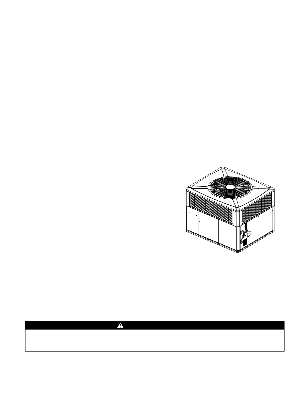
Installation and Operations Manual
Single Packaged Gas/Electric
13.4 SEER2 Convertible, 2 — 5 Ton
4YCC4024E1060A
4YCC4030E1070A
4YCC4036E1070A
4YCC4036E1090A
4YCC4042E1060A
4YCC4042E1090A
4YCC4048E1070A
4YCC4048E1090A
4YCC4060E1090A
4YCC4060E1115A
SSAAFFEETTYY WWAARRNNIINNGG
Only qualified personnel should install and service the equipment. The installation, starting up, and servicing of heating, ventilating, and air-conditioning
equipment can be hazardous and requires specific knowledge and training. Improperly installed, adjusted or altered equipment by an unqualified person
could result in death or serious injury. When working on the equipment, observe all precautions in the literature and on the tags, stickers, and labels that
are attached to the equipment.
March 2022 1188--EEBB4400DD11--11AA--EENN
Page 2
SAFETY SECTION
IImmppoorrttaanntt — This document contains a wiring
diagram, a parts list, and service information. This is
customer property and is to remain with this unit.
Please return to service information pack upon
completion of work.
WWAARRNNIINNGG
HHAAZZAARRDDOOUUSS GGAASSEESS!!
EExxppoossuurree ttoo ffuueell ssuubbssttaanncceess oorr bbyy--pprroodduuccttss ooff
iinnccoommpplleettee ffuueell ccoommbbuussttiioonn iiss bbeelliieevveedd bbyy tthhee
ssttaattee ooff CCaalliiffoorrnniiaa ttoo ccaauussee ccaanncceerr,, bbiirrtthh ddeeffeeccttss,, oorr
ootthheerr rreepprroodduuccttiivvee hhaarrmm..
TThhiiss wwaarrnniinngg ccoommpplliieess wwiitthh ssttaattee ooff CCaalliiffoorrnniiaa llaaww,,
PPrrooppoossiittiioonn 6655..
WWAARRNNIINNGG
HHAAZZAARRDDOOUUSS VVOOLLTTAAGGEE!!
FFaaiilluurree ttoo ffoollllooww tthhiiss WWaarrnniinngg ccoouulldd rreessuulltt iinn
pprrooppeerrttyy ddaammaaggee,, sseevveerree ppeerrssoonnaall iinnjjuurryy,, oorr
ddeeaatthh..
DDiissccoonnnneecctt aallll eelleeccttrriicc ppoowweerr,, iinncclluuddiinngg rreemmoottee
ddiissccoonnnneeccttss bbeeffoorree sseerrvviicciinngg.. FFoollllooww pprrooppeerr
lloocckkoouutt//ttaaggoouutt pprroocceedduurreess ttoo eennssuurree tthhee ppoowweerr
ccaannnnoott bbee iinnaaddvveerrtteennttllyy eenneerrggiizzeedd..
WWAARRNNIINNGG
SSAAFFEETTYY AANNDD EELLEECCTTRRIICCAALL HHAAZZAARRDD!!
FFaaiilluurree ttoo ffoollllooww tthhiiss WWaarrnniinngg ccoouulldd rreessuulltt iinn
pprrooppeerrttyy ddaammaaggee,, sseevveerree ppeerrssoonnaall iinnjjuurryy,, oorr
ddeeaatthh..
TThheessee sseerrvviicciinngg iinnssttrruuccttiioonnss aarree ffoorr uussee bbyy
qquuaalliiffiieedd ppeerrssoonnnneell oonnllyy.. TToo rreedduuccee tthhee rriisskk ooff
eelleeccttrriiccaall sshhoocckk,, ddoo nnoott ppeerrffoorrmm aannyy sseerrvviicciinngg
ootthheerr tthhaann tthhaatt ccoonnttaaiinneedd iinn tthheessee ooppeerraattiinngg
iinnssttrruuccttiioonnss uunnlleessss yyoouu aarree qquuaalliiffiieedd ttoo ddoo ssoo..
CCAAUUTTIIOONN
GGRROOUUNNDDIINNGG RREEQQUUIIRREEDD!!
FFaaiilluurree ttoo iinnssppeecctt oorr uussee pprrooppeerr sseerrvviiccee ttoooollss mmaayy
rreessuulltt iinn eeqquuiippmmeenntt ddaammaaggee oorr ppeerrssoonnaall iinnjjuurryy..
RReeccoonnnneecctt aallll ggrroouunnddiinngg ddeevviicceess.. AAllll ppaarrttss ooff tthhiiss
pprroodduucctt tthhaatt aarree ccaappaabbllee ooff ccoonndduuccttiinngg eelleeccttrriiccaall
ccuurrrreenntt aarree ggrroouunnddeedd.. IIff ggrroouunnddiinngg wwiirreess,, ssccrreewwss,,
ssttrraappss,, cclliippss,, nnuuttss,, oorr wwaasshheerrss uusseedd ttoo ccoommpplleettee aa
ppaatthh ttoo ggrroouunndd aarree rreemmoovveedd ffoorr sseerrvviiccee,, tthheeyy mmuusstt
bbee rreettuurrnneedd ttoo tthheeiirr oorriiggiinnaall ppoossiittiioonn aanndd pprrooppeerrllyy
ffaasstteenneedd..
WWAARRNNIINNGG
UUNNIITT CCOONNTTAAIINNSS RR--441100AA
RREEFFRRIIGGEERRAANNTT!!
FFaaiilluurree ttoo uussee pprrooppeerr sseerrvviiccee ttoooollss mmaayy rreessuulltt iinn
eeqquuiippmmeenntt ddaammaaggee oorr ppeerrssoonnaall iinnjjuurryy..
RR--441100AA ooppeerraattiinngg pprreessssuurree eexxcceeeeddss tthhee lliimmiitt ooff RR--
2222.. PPrrooppeerr sseerrvviiccee eeqquuiippmmeenntt iiss rreeqquuiirreedd.. SSeerrvviiccee
uussiinngg oonnllyy RR--441100AA RReeffrriiggeerraanntt aanndd aapppprroovveedd PPOOEE
ccoommpprreessssoorr ooiill..
WWAARRNNIINNGG
SSAAFFEETTYY HHAAZZAARRDD!!
OOppeerraattiinngg tthhee uunniitt wwiitthhoouutt tthhee aacccceessss ppaanneellss
pprrooppeerrllyy iinnssttaalllleedd mmaayy rreessuulltt iinn sseevveerree ppeerrssoonnaall
iinnjjuurryy oorr ddeeaatthh..
DDoo nnoott ooppeerraattee tthhee uunniitt wwiitthhoouutt tthhee eevvaappoorraattoorr ffaann
aacccceessss ppaanneell oorr eevvaappoorraattoorr ccooiill aacccceessss ppaanneell iinn
ppllaaccee..
WWAARRNNIINNGG
WWAARRNNIINNGG!!
TThhiiss pprroodduucctt ccaann eexxppoossee yyoouu ttoo cchheemmiiccaallss
iinncclluuddiinngg lleeaadd,, wwhhiicchh aarree kknnoowwnn ttoo tthhee SSttaattee ooff
CCaalliiffoorrnniiaa ttoo ccaauussee ccaanncceerr aanndd bbiirrtthh ddeeffeeccttss oorr
ootthheerr rreepprroodduuccttiivvee hhaarrmm.. FFoorr mmoorree iinnffoorrmmaattiioonn ggoo
ttoo wwwwww..PP6655WWaarrnniinnggss..ccaa..ggoovv..
©2022
IImmppoorrttaanntt:: Wear appropriate gloves, arm sleeve
protectors and eye protection when
servicing or maintaining this equipment.
IImmppoorrttaanntt:: Air filters and media wheels or plates shall
meet the test requirements in UL 900.
18-EB40D1-1A-EN
Page 3

Table of Contents
Introduction, Unit Inspection and
Specification . . . . . . . . . . . . . . .. . . . . . . . . . . . . . . . 4
Introduction . . . . . . . . . . . . . . . . . . . . . . . . . . . . . . 4
Inspect Shipment . . . . . . . . . . . . . . . . . . . . . . . . . 4
Product Specifications . . . . . . . . . . . . . . . . . . . . 5
Charging in Cooling above 55°F OD
Ambient . . . . . . . . . . . . . . . . . . . . . . . . . . . . . . . . . 7
Determine Unit Clearances . . . . . . . . . . . . . . . . . 8
Review Location and Recommendation
Information. . . . . . . . . . .. . . . . . . . . . . . . . . . . .. . . 10
Unit Installation . . . . . . . . . .. . . . . . . . . . . . . . . . . 12
Install Flue Hood. . . . . . . . . . . . . . . . . . . . . . . . . 12
Ground Level Installation. . . . . . . . . . . . . . . . . 12
Rooftop Installation—Curb
Mounting . . . . . . . . . . . . . . . . . . . . . . . . . . . . . . . 12
. . . . . . . . . . . . . . . . . . . . . . . . . . . . . . . . . . . . . . . . 12
Lifting and Rigging. . . . . . . . . . . . . . . . . . . 13
Rooftop Installation — Frame
Mounting . . . . . . . . . . . . . . . . . . . . . . . . . . . . . . . 14
Rooftop Installation — No Curb/
Frame . . . . . . . . . . . . . . . . . . . . . . . . . . . . . . . . . . 15
Ductwork Installation . . . . . . . . . . . . . . . . . . . . 17
Attaching Downflow Ductwork to
Roof Curb . . . . . . . . . . . . . . . . . . . . . . . . . . . 17
Attaching Downflow Ductwork to
Roof Frame. . . . . . . . . . . . . . . . . . . . . . . . . . 17
Gas Piping Installation. . . . . . . . . . . . . . . . 18
Air Filter Installation . . . . . . . . . . . . . . . . . . . . . 21
Electrical Wiring . . . . . . . . . . . . . . . . . . . . . . . . . 22
Unit Startup . . . . . . . . . . . .. . . . . . . . . . . . . . . . . . . 24
Pre-Start Quick Checklist . . . . . . . . . . . . . . . . . 24
Starting the Unit in Cooling Mode. . . . . . . . . 24
Starting the Unit in Heating Mode. . . . . . . . . 24
Sequence of Operation. . . . . . . . . . . . . . . . . . . 25
Final Installation Checklist . . . . . . . . . . . . 26
Maintenance . . . . . . . . . . . . . . . . . . . . . . . . . . . . 26
Service Maintenance . . . . . . . . . . . . . . . . . 26
Pressure Curves . . . . . . . . . . . . . . . . . . . . . . . . . 29
Indoor Fan Performance. . . . . . . . . . . . . . . . . . 35
Refrigerant Circuit . . . . . . . . . . . . . . . . . . . . . . . 41
Troubleshooting Chart . . . . . . . . . . . . . . . . . . . 42
Important Product Information . . . . . . . . . 44
18-EB40D1-1A-EN
3
Page 4

Introduction, Unit Inspection and Specification
Introduction
Read this manual carefully before attempting to install,
operate, or perform maintenance on this unit.
Installation and maintenance should be performed by
qualified service technicians only. This unit is listed by
Underwriters Laboratory. DO NOT use this furnace for
temporary heating of buildings under construction.
As shipped from the factory, this unit is for use with
natural gas only. It is listed by Underwriters
Laboratory. An LPG conversion kit is available. A high
altitude installation kit of additional orifice sizes is
available. Extreme mounting kits for slab and curbs are
also available.
Packaged units are designed for outdoor mounting
with a vertical condenser discharge. They can be
located either at ground level or on a roof in
accordance with local codes or National Fuel Gas Code
(ANSI-Z223.1A) Latest Revision. Since these units are
designed exclusively for outdoor operation, additional
flue venting systems are not required. Each unit
contains an operating charge of refrigerant as shipped.
Extreme mounting kits are available for slab
(BAYEXMK003A), utility curb (BAYEXMK002B) and
perimeter curb (BAYEXMK001A) mountings.
Inspect Shipment
1. Check for damage after the unit is unloaded. Report
promptly to the carrier any damage found to the
unit. Do not drop the unit.
IImmppoorrttaanntt:: To prevent damage to the sides and top
of the unit when hoisting, use
“spreader bars” see, “Rooftop
Installation — No Curb/Frame,” p. 15
2. Check the unit’s nameplate to determine if the unit
is correct for the intended application. The power
supply must be adequate for both the unit and all
accessories.
3. Check to be sure the refrigerant charge has been
retained during shipment. Remove the Compressor
access panel to access the 1/4" flare pressure taps.
4. The Flue Hood is included with the unit’s literature
pack.
5. If this unit is being installed on a curb, verify that
the correct curb is provided with the unit.
• 4YCC4024–4036 use model BAYCURB050A
• 4YCC4042–4060 use model BAYCURB051A
6. If the unit is being hoisted, accessory kit
BAYLIFT002B is recommended. It includes a kit of
four (4) lifting lugs and instructions.
NNootteess::
• If practical, install any internal accessories to
the unit at the shop.
• The packaged units have been evaluated in
accordance with the Code of Federal
Regulations, Chapter XX, Part 3280 or the
equivalent. “SUITABLE FOR MOBILE HOME
USE”.
4
18-EB40D1-1A-EN
Page 5
IInnttrroodduuccttiioonn,, UUnniitt IInnssppeeccttiioonn aanndd SSppeecciiffiiccaattiioonn
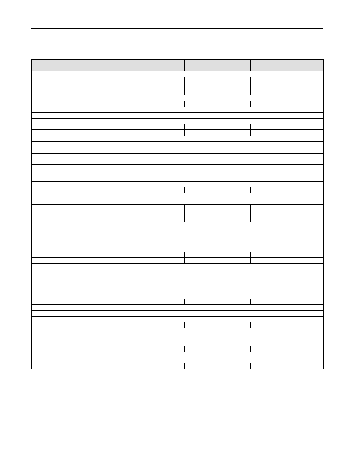
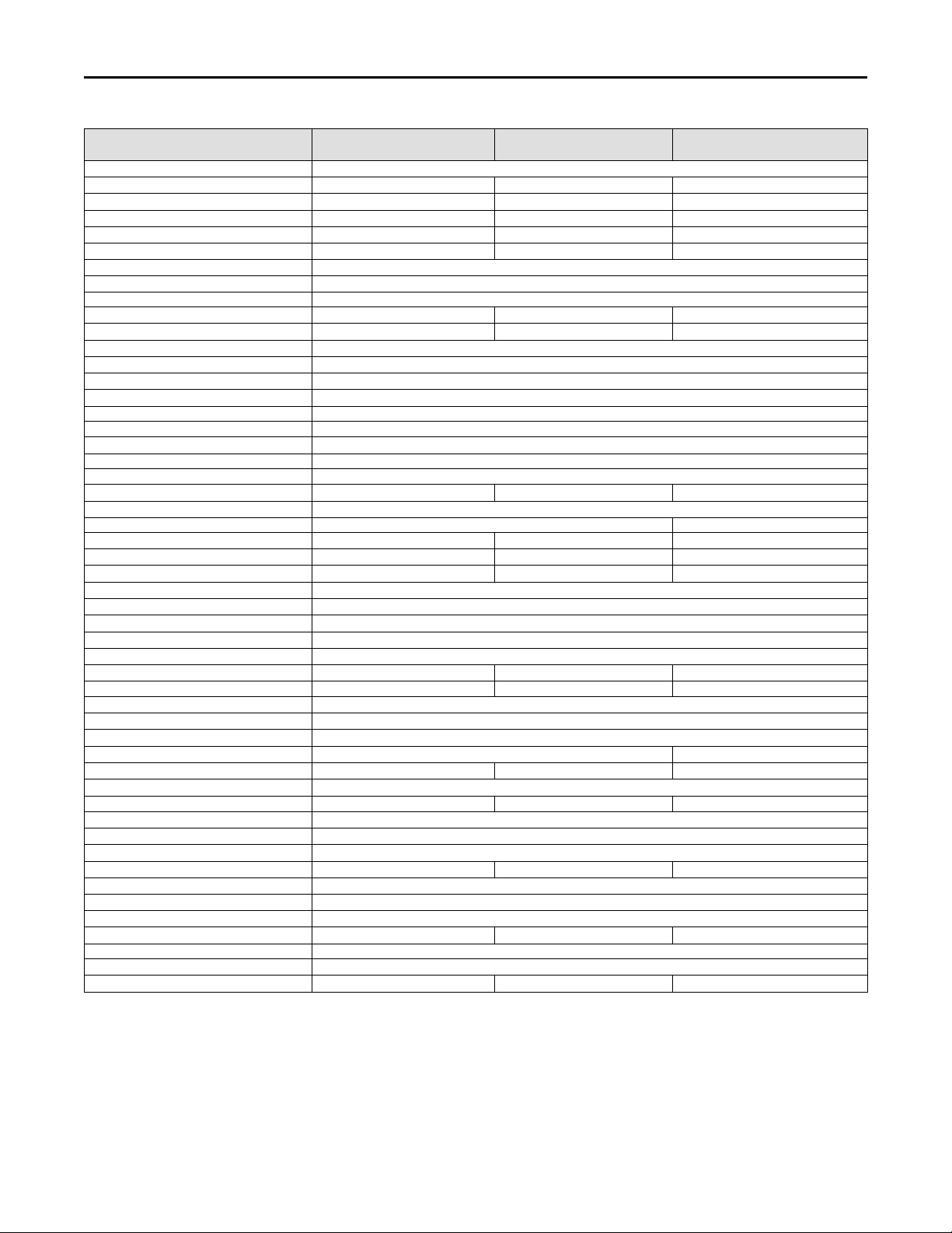
Product Specifications
MODEL 4YCC4024*1 4YCC4030*1
RATED Volts/PH/Hz 208–230/1/60
Performance Cooling BTUH
Indoor Airflow (CFM)
Power Input (KW)
(a)
23200 28000 36400
785 880 1215
1.94 2.21 3.17
EER2/SEER2 BTU/Watt-Hr 11.00 / 13.40
Sound Power Rating [dB(A)]
PERFORMANCE HEATING
Input BTUH-1st Stage (Natural Gas)
(b)
(c)
(d)
66.6 70 69.3
LOCATED ON UNIT NAMEPLATE
AFUE 81
Temp. Rise -min/max (°F)
30/60 30/60
Orifice Qty/drill size (Nat Gas) 2 / #37 2 / #33 2 / #33 [3 / #37]
POWER CONN. — V/Ph/Hz 208–230/1/60
Min. Brch. Cir. Ampacity
Fuse Size — Max. (amps)
Fuse Size — Recmd. (amps)
(e)
LOCATED ON UNIT NAMEPLATE
LOCATED ON UNIT NAMEPLATE
LOCATED ON UNIT NAMEPLATE
COMPRESSOR SCROLL
VOLTS/PH/HZ 208–230/1/60
R.L. Amps — L.R. Amps
LOCATED ON UNIT NAMEPLATE
OUTDOOR COIL — TYPE SPINE FIN
Rows/F.P.I 2 / 24
Face Area (sq. ft.)
Tube Size (in.)
13.2 13.3 15.5
3/8
INDOOR COIL — TYPE MCHE
Rows/F.P.I 2/16 2/16 2/16
Face Area (sq. ft.)
Tube Size (in.)
Refrigeration Control
Drain Conn. Size (in.)
OUTDOOR FAN — TYPE
DIA. (IN.)
2.7 2.7 2.7
0.81 0.81 1
EXPANSION VALVE
3/4 FEMALE NPT
Swept
23.4
DRIVE/NO. SPEEDS DIRECT / 1
CFM @ 0.0 in. w.g.
(f)
2350 2800 3080
Motor — HP/R.P.M 1/12 / 810 1/6 / 825 1/5 /825
Volts/Ph/Hz 208–230/1/60
F.L. Amps/L.R Amps
INDOOR FAN — TYPE
Dia. x Width (in.)
Drive/No. Speeds
CFM @ 0.0 in. w.g.
(g)
LOCATED ON UNIT NAMEPLATE
Const. Torque ECM
10.62 x 10.62
DIRECT / 4
SEE FAN PERFORMANCE TABLE
Motor — HP / R.P.M. 1/3 / 1050 1/2 / 1050 3/4 / 1050
Volts/Ph/Hz 208–230/1/60
COMBUSTION FAN-TYPE
Drive / no. Speeds
Centrifugal
Direct 1
Motor- HP / R.P.M. 1/34 /3345 1/34 /3290 1/34 /3290
F.L. Amps
FILTER / FURNISHED
Type Recommended
Recmd. Face Area (sq. ft)
(h)
4.0 4.0 4.0
LOCATED ON UNIT NAMEPLATE
NO
THROWAWAY
REFRIGERANT R-410
Charge (lbs.)
Subcooling
(a)
Rated in accordance with AHRI Standard 210/240. AHRI standard rating conditions are: 80 D.B.67 W.B. entering air to indoor coil. 95 D. B. entering air to
outdoor coil.
(b)
Sound Power values are not adjusted for AHRI 270–95 tonal corrections.
(c)
Ratings shown are for elevations up to 2000 ft. For higher elevations reduce ratings at a rate of 4% per 1000 ft. elevation.
(d)
Convertible to LPG.
(e)
This value is approximate. For more precise value, see Unit Nameplate.
(f)
Standard Air — Dry Coil — Outdoor.
(g)
Based on U.S. Government Standard Tests.
(h)
Filters must be installed in return air stream. Square footages listed are based on 300 f.p.m. face velocity. If permanent filters are used size per
manufacturer’s recommendation with a clean resistance of 0.05” W.C.
10° 8° 11°
LOCATED ON UNIT NAMEPLATE
4YCC4036*1070
[4YCC4036*1090]
30/60 [35/65]
18-EB40D1-1A-EN
5
Page 6
IInnttrroodduuccttiioonn,, UUnniitt IInnssppeeccttiioonn aanndd SSppeecciiffiiccaattiioonn
MODEL
4YCC4042*1060
[4YCC4042*1090]
4YCC4048*1070
[4YCC4048*1090]
4YCC4060A*1090
[4YCC4060A*1115]
RATED Volts/PH/Hz 208–230/1/60
Performance Cooling BTUH
Indoor Airflow (CFM)
Power Input (KW)
(a)
40000 46000 57500
1450 1625 1770
3.53 4.20 4.98
EER2/SEER2 BTU/Watt-Hr 11.00 / 13.40 10.80 / 13.40 11.00 / 13.40
Sound Power Rating [dB(A)]
PERFORMANCE HEATING
Input BTUH-1st Stage (Natural Gas)
(b)
(c)
(d)
74.6 72.5 73.1
LOCATED ON UNIT NAMEPLATE
AFUE 81
Temp. Rise -min/max (°F) 30/60 [35/65] 30/60 [35/65] 30 / 60
Orifice Qty/drill size (Nat Gas) 2 / #33 [3 / #37] 2 / #33 [3 / #37] 3 / #37 [3 / #33]
POWER CONN. — V/Ph/Hz 208–230/1/60
Min. Brch. Cir. Ampacity
Fuse Size — Max. (amps)
Fuse Size — Recmd. (amps)
(e)
LOCATED ON UNIT NAMEPLATE
LOCATED ON UNIT NAMEPLATE
LOCATED ON UNIT NAMEPLATE
COMPRESSOR SCROLL
VOLTS/PH/HZ 208–230/1/60
R.L. Amps — L.R. Amps
LOCATED ON UNIT NAMEPLATE
OUTDOOR COIL — TYPE SPINE FIN
Rows/F.P.I 2 / 24
Face Area (sq. ft.)
Tube Size (in.)
15.6 20.5 23.0
3/8
INDOOR COIL — TYPE MCHE Plate Fin
Rows/F.P.I 2 / 16 2 / 16 4 / 15
Face Area (sq. ft.)
Tube Size (in.)
Refrigeration Control
Drain Conn. Size (in.)
OUTDOOR FAN — TYPE
DIA. (IN.)
3.9 3.9 5.0
0.81 0.81
EXPANSION VALVE
3/4 FEMALE NPT
Swept
28.5
3/8
DRIVE/NO. SPEEDS DIRECT / 1
CFM @ 0.0 in. w.g.
(f)
3400 4800 4800
Motor — HP/R.P.M 1/4 / 825 1/4 / 825 1/3/825
Volts/Ph/Hz 208–230/1/60
F.L. Amps/L.R Amps
INDOOR FAN — TYPE
Dia. x Width (in.)
Drive/No. Speeds
CFM @ 0.0 in. w.g.
(g)
DIRECT / 4 DIRECT / 5 DIRECT / 4
LOCATED ON UNIT NAMEPLATE
Const. Torque ECM
10.62 x 10.62 11.87 x 10.68
SEE FAN PERFORMANCE TABLE
Motor — HP / R.P.M. 3/4 /1050 3/4 /1050 1 / 1050
Volts/Ph/Hz 208–230/1/60
COMBUSTION FAN-TYPE
Drive / no. Speeds
Centrifugal
Direct 1
Motor- HP / R.P.M. 1/34 / 3345 1/34 /3290 1/34 / 3075 [1 /34 / 3055]
F.L. Amps
FILTER / FURNISHED
Type Recommended
Recmd. Face Area (sq. ft)
(h)
5.3 5.3 5.3
LOCATED ON UNIT NAMEPLATE
NO
THROWAWAY
REFRIGERANT R-410
Charge (lbs.)
Subcooling
(a)
Rated in accordance with AHRI Standard 210/240. AHRI standard rating conditions are: 80 D.B.67 W.B. entering air to indoor coil. 95 D. B. entering air to
outdoor coil.
(b)
Sound Power values are not adjusted for AHRI 270–95 tonal corrections.
(c)
Ratings shown are for elevations up to 2000 ft. For higher elevations reduce ratings at a rate of 4% per 1000 ft. elevation.
(d)
Convertible to LPG.
(e)
This value is approximate. For more precise value, see Unit Nameplate.
(f)
Standard Air — Dry Coil — Outdoor.
(g)
Based on U.S. Government Standard Tests.
(h)
Filters must be installed in return air stream. Square footages listed are based on 300 f.p.m. face velocity. If permanent filters are used size per
manufacturer’s recommendation with a clean resistance of 0.05” W.C.
10° 10° 11°
LOCATED ON UNIT NAMEPLATE
6
18-EB40D1-1A-EN
Page 7
IInnttrroodduuccttiioonn,, UUnniitt IInnssppeeccttiioonn aanndd SSppeecciiffiiccaattiioonn
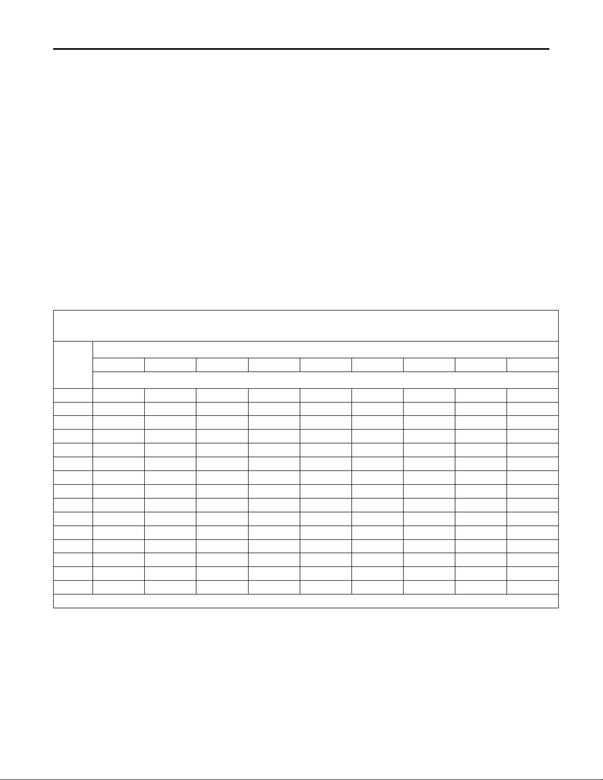
Charging in Cooling above 55°F OD Ambient
If servicing the equipment requires system evacuation,
then re-charge the system to the weight specified on
the nameplate. Verify the system subcooling using the
Subcooling Charging Table and, if necessary, adjust
the charge using the procedure below.
1. For best results — the indoor temperature should
be kept between 70°F to 80°F. Add system heat if
needed.
2. Whenever charge is removed or added, the system
must be operated for a minimum of 20 minutes to
stabilize before accurate measurements can be
made.
3. Measure Liquid Line Temperature and Refrigerant
Pressure at service valved in the compressor
compartment.
pressure under the subcool value column, Add
refrigerant to raise the pressure to match the table,
or remove refrigerant to lower the pressure. Again,
wait 20 minutes for the system conditions to
stabilize before adjusting charge again.
NNoottee:: System charge shall never be more than 110% or
less than 90% of nameplate charge. If specified
subcooling cannot be achieved within those
charge bounds, contact your Field Service
Representative.
5. When system is correctly charged, you can refer to
System Pressure Curves to verify typical
performance.
CCHHAARRGGIINNGG BBEELLOOWW 5555°°FF
Evacuate system and weigh in nameplate charge or
use factory charge. Correct subcooling may be verified
when the temperature is above 55°F.
4. Locate your liquid line temperature in the left
column of the table, and the intersecting liquid line
Refer to Service Facts or Installer’s Guide for charging method
LIQUID
TEMP
(°F)
55 174 179 182 185 188 191 195 198 205
60 189 195 198 201 204 208 211 215 222
65 205 211 215 218 222 225 229 232 240
70 222 229 232 236 240 243 247 251 259
75 240 247 251 255 259 263 267 271 279
80 259 267 271 275 279 283 287 291 301
85 279 287 291 296 300 304 309 313 323
90 301 309 313 318 322 327 331 336 347
95 323 331 336 341 346 351 355 360 371
100 347 355 360 365 370 376 381 386 398
105 371 381 386 391 396 402 407 413 425
110 398 407 413 418 424 429 435 441 454
115 425 435 441 446 452 458 464 470 484
120 454 464 470 476 482 488 495 501 516
125 484 495 501 507 514 520 527 533 549
From Dwg. D154557P01
6 8 9 10 11 12 13 14 16
R-410A REFRIGERANT CHARGING CHART
DESIGN SUBCOOLING (°F)
LIQUID GAGE PRESSURE (PSI)
18-EB40D1-1A-EN
7
Page 8
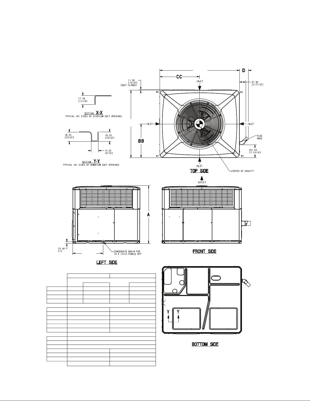
Determine Unit Clearances
Note: The view labeled “Bottom side”
represents the base as viewed looking
up from underneath the unit.
W/ ECONOMIZER W / ECONOMIZER
BACK SIDE 305 [12] 762 [30] 305 [12] 762 [30]
LEFT SIDE 762 [30] 914 [36] 914 [36] 1067 [42]
RIGHT SIDE 610 [24] - 610 [24] FRONT SIDE 1067 [42] - 762 [30] -
BOTTOM
BACK SIDE
LEFT SIDE
RIGHT SIDE
FRONT SIDE
TOP
A HEIGHT OF UNIT - TABLE NEXT PAGE
BB CENTER OF GRAVITY - TAB LE NEXT PAGE
CC CENTER OF GRAVITY - TABLE NEXT PAGE
DD -Depth
EE -Width
FF
25 [1]
0
25 [1]
DIMENSIONS mm [Inches]
2 - 3 TON Units 3.5 - 5 TON Units
RECOMMENDED SERVI CE CLEARANCE mm [Inches]
CLEARANCE TO COMBUSTI BLE MATERIAL mm [Inches]
0
2 - 3 TON 3.5 - 5 TON
152 [6]
152 [6]
305 [12]
914 [36]
1049.02 [41-5/16]
1240.28 [48.27-27/32]
152 [6]
152 [6]
305 [12]
914 [36]
475.23 [18-23/32]
1125.22 [44-5/16]
1487.17 [58-9/16]
551.43 [21-23/32]
FF
DD
EE
Figure 1. Space on Sides Requirements
8
18-EB40D1-1A-EN
Page 9
B C D E F G H I J K L M N
4YCC4024
4YCC4030
4YCC4036
4YCC4042
4YCC4048
4YCC4060
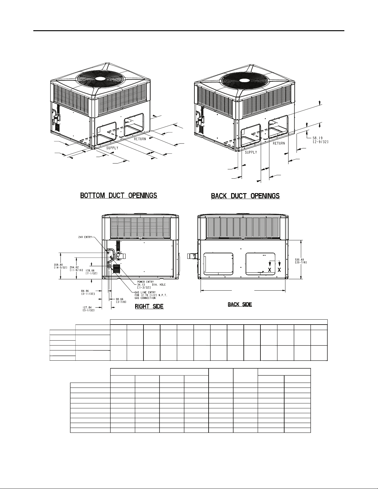
PHYSICAL DIMENSIONS mm [In]
304.80
[12]
75.41
[2.93]
75.41
[2.93]
406.40
[16]
167.89
[6.61]
173.46
[6-27/32]
304.80
[12]
79.50
[3.13]
398.22
[15.68]
176.07
[6.93]
177.55
[6.99]
296.62
[11.68]
1155.45
[45.49]
457.20
[18]
75.41
[2.97]
75.41
[2.97]
381.00
[15]
322.84
[12.71]
372.82
[14.68]
1402.34
[55.21]
244.09
[9.61]
318.75
[12.55]
381.00
[15]
79.50
[3.13]
449.02
[17.68]
176.07
[6.93]
W1 W2 W3 W4 BB CC
4YCC4024* (060) 58 [129] 37 [81]
26 [58] 41 [90] 196 [432] 162 [358] 480 [19] 528 [21]
4YCC4030* (070) 61 [135] 39 [85]
28 [61] 43 [95] 205 [451] 171 [377] 407 [16] 594 [23]
4YCC4036* (070) 61 [134] 39 [84]
28 [60] 43 [95] 205 [438] 171 [374] 407 [16] 594 [28]
4YCC4036* (090) 61 [136] 39 [86]
4YCC4042*(060) 71 [157] 47 [103]
35 [76] 53 [117] 252 [555] 202 [202] 470 [19] 731 [29]
4YCC4042*(090) 72 [158] 47 [104]
35 [78] 54 [118] 255 [561] 207 [202] 470 [19] 731 [29]
4YCC4048*(070) 71 [157] 45 [98]
33 [73] 54 [119] 250 [552] 202 [448] 433 [17] 743 [29]
4YCC4048*(090) 72 [159] 45 [99]
34 [75] 55 [120] 253 [557] 205 [453] 433 [17] 743 [29]
4YCC4060*(090) 77 [170] 46 [101]
35 [76] 58 [128] 263 [580] 216 [476] 433 [17] 743 [29]
4YCC4060*(115) 78 [172] 46 [102]
35 [77] 59 [130] 266 [586] 219 [482] 414 [16] 635 [25]
Corner Weights
KG/LBS
SHIPPING
WEIGHT
KG/LBS
UNIT
WEIGHT
KG/LBS
Center Of Gra vity
mm [inch]
I
J
J
L
M
G
B
E
D
F
E
C
K
H
HEIGHT-A
mm [inch]
898.53 [35-3/8]
949.33 [37-3/8]
898.53 [35-3/8]
1000.13 [35-3/8]
N
28 [61] 43 [96]
205 [453] 171 [379] 407 [16] 594 [28]
DDeetteerrmmiinnee UUnniitt CClleeaarraanncceess
Figure 2. Bottom and Back Duct Openings
18-EB40D1-1A-EN
9
Page 10

Review Location and Recommendation Information
NNootteess::
• The unit is shipped for horizontal installation.
• During heating operation, avoid supply air
below 80 degrees F or return air below 50
degrees F to prevent flue gas condensation.
HHoorriizzoonnttaall AAiirrffllooww UUnniittss
1. Location of the unit must allow service clearance
around it to ensure adequate serviceability,
maximum capacity, and peak operating efficiency.
2. These units are designed for outdoor installation.
They may be installed directly on a slab, wood
flooring, or on Class A, B, or C roof covering
material. The discharge air from the condenser fans
must be unrestricted for a minimum of 3 feet above
the unit.
3. The louvers above and below the flue hood in the
side panel must have adequate clearance around
the air opening into the combustion area.
4. Examine all flue product-carrying areas of the
furnace, its vent system, and the main burner for
safe operation.
IImmppoorrttaanntt:: A minimum clearance of 0.0” to
combustible material shall be
maintained on air outlet duct.
5. Exhaust vents or other sources of contaminated air
must not be near the unit’s air inlet if outside air is
to be introduced as make-up air or a ventilation
feature is to be used. Contamination from exhaust
vents or chimneys may also foul the condenser
causing degraded performance.
6. Check the handling facilities to ensure the safety of
personnel and the unit(s).
7. The unit must be mounted level for proper drainage
of water through the drain holes in the base pan.
8. The unit should not be exposed to direct roof water
runoff.
9. Flexible duct connectors must be of a flame
retardant material. All duct work outside of the
structure must be insulated and weatherproofed in
accordance with local codes.
10. Holes through exterior walls or roof must be sealed
in accordance with local codes.
11. All fabricated outdoor ducts should be as short as
possible.
CClleeaarraanncceess
1. The recommended clearances for single-unit
installations are illustrated in “ Determine Unit
Clearances,” p. 8.
2. Any reduction of the unit clearances indicated in
these figures may result in condenser coil
starvation or the recirculation of warm condenser
air. Actual clearances, which appear to be
inadequate should be reviewed with a local
engineer.
3. See the unit’s nameplate for the absolute minimum
clearance between the unit and any combustible
surfaces.
DDoowwnn AAiirrffllooww UUnniittss
1. Location of the unit must allow service clearance
around it to ensure adequate serviceability,
maximum capacity, and peak operating efficiency.
2. Refer to the Installation section for instruction on
converting the supply and return airflow covers to
down airflow.
3. The field assembled Roof Mounting Curb
(BAYCURB050A or BAYCURB051A) or a field
fabricated curb should be in place before the unit is
hoisted to the roof top.
The Roof Mounting Curb (frame) must be installed
on a flat, level section of the roof (maximum of 1/4"
per foot pitch) and provide a level mounting surface
for the unit. Also, be sure to provide sufficient
height above the roof to prevent water from
entering the unit.
4. Be sure the mounting curb spans structural
members (trusses) of the roof, thereby providing
sufficient support for the weight of the unit, the
curb, the duct(s), and any factory or field installed
accessories.
5. The unit must be mounted level for proper drainage
of water through the drain holes in the base pan.
6. Be sure the hole in the structure for the ducts is
large enough to accommodate the fabricated ducts
and the insulation surrounding them. Flexible duct
connectors must be of a flame retardant material.
All duct work outside of the structure must be
insulated and weatherproofed in accordance with
local codes.
7. Holes through exterior walls or roof must be sealed
in accordance with local codes.
8. These units are design certified for outdoor
installation. They may be installed directly on a
slab, wood flooring, or on Class A, B, or C roof
covering material. The discharge air from the
condenser fans must be unrestricted for a minimum
of 3 feet above the unit.
9. The louvers above and below the flue hood in the
side panel must have adequate clearance around
the air opening into the combustion area.
10. Examine all flue product-carrying areas of the
furnace, its vent system, and the main burner for
safe operation.
IImmppoorrttaanntt:: A minimum clearance of 0.0” to
combustible material shall be maintained
on air outlet duct.
10
18-EB40D1-1A-EN
Page 11

RReevviieeww LLooccaattiioonn aanndd RReeccoommmmeennddaattiioonn IInnffoorrmmaattiioonn
11. Exhaust vents or other sources of contaminated air
should not be near the unit’s air inlet if outside air is
to be introduced as make-up air or a ventilation
feature is to be used. Contamination from exhaust
vents or chimneys may also foul the condenser
causing degraded performance.
12. Check the handling facilities to ensure the safety of
personnel and the unit(s).
CClleeaarraanncceess
1. The recommended clearances for single-unit
installations are illustrated in “ Determine Unit
Clearances,” p. 8.
2. Any reduction of the unit clearances indicated in
these figures may result in condenser coil
starvation or the recirculation of warm condenser
air. Actual clearances, which appear to be
inadequate should be reviewed with a local
engineer.
3. See the unit’s nameplate for the absolute minimum
clearance between the unit and any combustible
surfaces.
18-EB40D1-1A-EN
11
Page 12

Unit Installation
NNoottee:: The factory ships this unit for horizontal
installation.
Install Flue Hood
1. Locate the Flue Hood in the literature package.
2. Remove the two Flue Hood mounting screws from
the unit. They are located to the right of the Power
Entry connection panel.
3. Attach the Flue Hood to the unit with the two
screws removed in step two.
Ground Level Installation
1. Place the unit on a pad the size of the unit or larger.
The unit must be mounted level for proper drainage
of water through the holes in the base pan. To
attach the unit securely to the slab, use extreme
mounting kit, BAYEXMK003A.
The pad must not come in contact with the
structure. Be sure the outdoor portion of the supply
and return air ducts are as short as possible.
Unit requires vibration support as indicated in Table
3, p. 14
2. The louvers above and below the Flue Hood in the
side panel must have adequate clearance around
the air opening into the combustion area.
3. Location of the unit must allow service clearance
around it. Clearance of the unit must be given
careful consideration. See “ Determine Unit
Clearances,” p. 8
NNoottee:: Any reduction of the unit clearances indicated in
these illustrations may result in condenser coil
starvation or the recirculation of warm
condenser air. Actual clearances, which appear
to be inadequate should be reviewed with a local
engineer.
IImmppoorrttaanntt:: A minimum clearance of 0.0" to
combustible material shall be maintained
on air outlet duct.
4. Attach the supply and return air ducts to the unit as
explained in the Ductwork Installation section.
5. Flexible duct connectors must be of a flame
retardant material. Insulate any ductwork outside of
the structure with at least two (2) inches of
insulation and weatherproof. There must be a
weatherproof seal where the duct enters the
structure.
6. Do not expose the unit to direct roof water runoff.
7. Seal all holes through exterior walls in accordance
with local codes.
8. Continue with the following installation sections to
complete the installation: Ductwork, Gas Piping,
Filter and Electrical Wiring.
Rooftop Installation—Curb Mounting
CCoonnvveerrtt HHoorriizzoonnttaall AAiirrffllooww ttoo DDoowwnn AAiirrffllooww
The factory ships the unit for horizontal airflow.
Perform this procedure to convert it to down airflow:
1. Remove the three (3) sheet metal screws securing
the supply air cover and the four (4) sheet metal
screws securing the return air cover from the base
of the unit. Remove the covers from the base.
2. Place the covers over the horizontal supply and
return openings (painted side out). Align the screw
holes, and secure using the same screws removed
in step 1.
IInnssttaallll FFuullll PPeerriimmeetteerr RRooooff MMoouunnttiinngg CCuurrbb
1. Verify that the roof mounting curb is correct for the
unit. There are two curbs depending on the unit
cabinet sizes:
• 4YCC4024–036 use model BAYCURB050A
• 4YCC4042–060 use model BAYCURB051A
2. Assemble and install the curb following the
instructions in the Installer's Guide included with
the appropriate curb.
12
18-EB40D1-1A-EN
Page 13
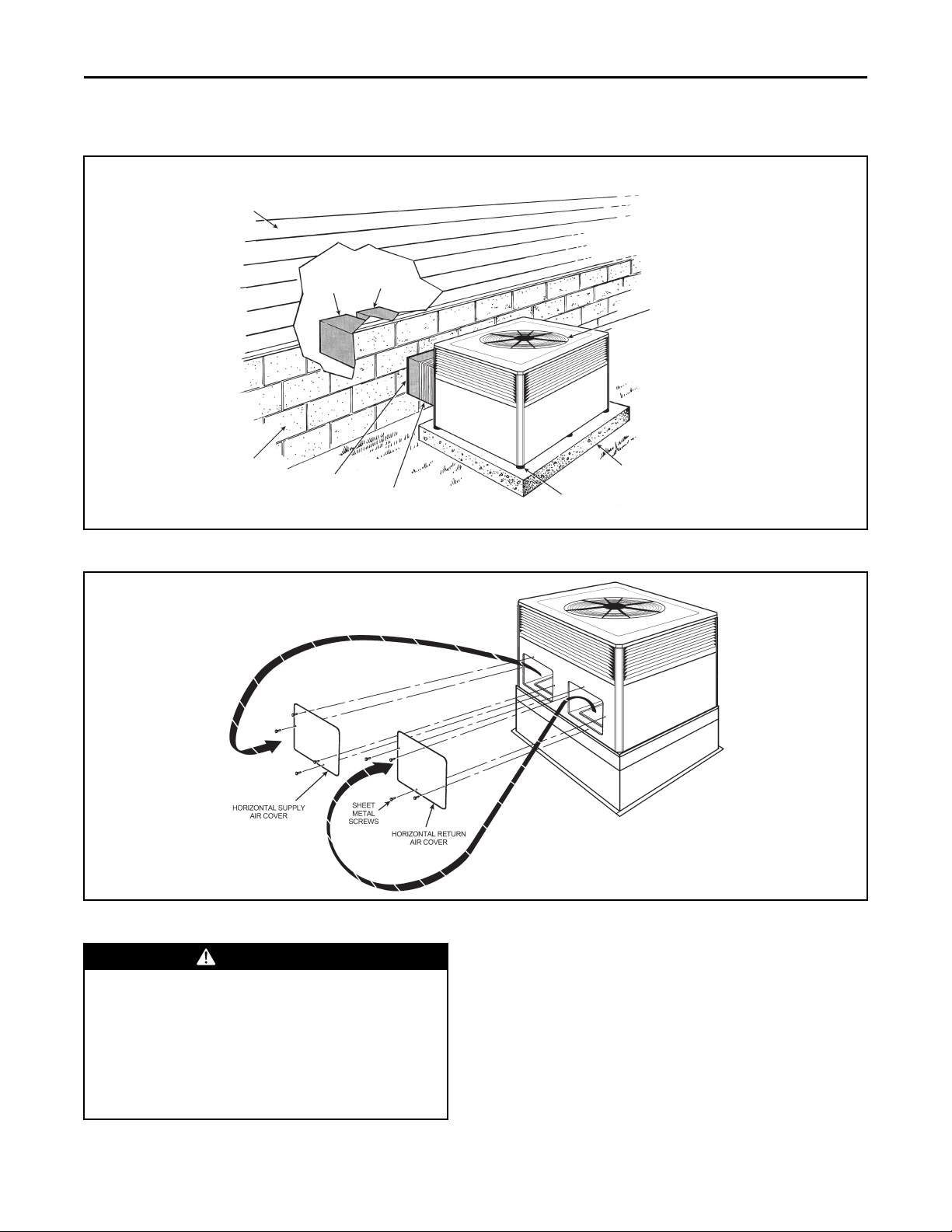
Table 1. Typical Ground Level Application
SIDING
RETURN
AIR DUCT
SUPPLY
AIR DUCT
EXTERIOR
WALL
INSULATE
WEATHERPROOF
OR RAIN SHIELD
FLEXIBLE DUCT
CONNECTORS
OUTDOOR
AIR DISCHARGE
SUPPORT PAD
FOUNDATION
3/4” VIBRATION ISOLATORS, USE
7 ISOLATORS
Note: Use the extreme mounting kit, BAYEXMK003AA, to secure the unit to the slab.
UUnniitt IInnssttaallllaattiioonn
Table 2. Converting Horizontal to Down Airflow
Lifting and Rigging
WWAARRNNIINNGG
IIMMPPRROOPPEERR UUNNIITT LLIIFFTT!!
FFaaiilluurree ttoo pprrooppeerrllyy lliifftt uunniitt ccoouulldd rreessuulltt iinn ddeeaatthh oorr
sseerriioouuss iinnjjuurryy oorr ppoossssiibbllee eeqquuiippmmeenntt oorr pprrooppeerrttyy-oonnllyy ddaammaaggee..
TTeesstt lliifftt uunniitt aapppprrooxxiimmaatteellyy 2244 iinncchheess ttoo vveerriiffyy
pprrooppeerr cceenntteerr ooff ggrraavviittyy lliifftt ppooiinntt.. TToo aavvooiidd
ddrrooppppiinngg ooff uunniitt,, rreeppoossiittiioonn lliiffttiinngg ppooiinntt iiff uunniitt iiss
nnoott lleevveell..
IImmppoorrttaanntt:: Do not lift the unit without test lifting for
balance and rigging. Do not lift the unit in
windy conditions or above personnel. Do
not lift the unit by attaching clevis, hooks,
pins, or bolts to the unit casing, casing
hardware, corner lugs, angles, tabs, or
flanges. Failure to observe these warnings
may result in equipment damage.
1. Before preparing the unit for lifting, check the unit
dimension drawings for center of gravity for lifting
safety (“ Determine Unit Clearances,” p. 8).
Because of placement of internal components, the
unit’s weight may be unevenly distributed.
18-EB40D1-1A-EN
13
Page 14
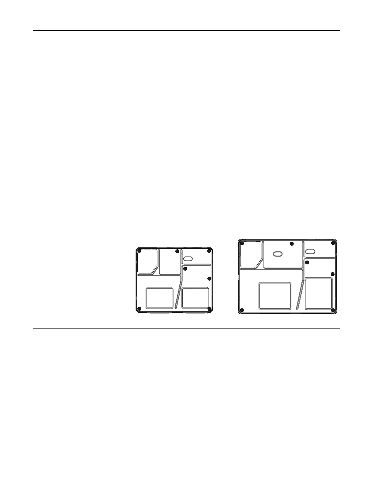
Small Cabinet
****4024 - 4036
Medium Cabinet
****4042 - 4060
UUnniitt IInnssttaallllaattiioonn
Approximate unit weights are also provided in the
unit drawings.
NNoottee:: Unit rigging and hoisting requires accessory
kit BAYLIFT002BA. It includes a kit of four (4)
lifting lugs.
2. Insert the four lifting lugs in the openings provided
in the drip lip on each end of the unit. A tap or jerk
to the lug will overcome the interference that arises
due to the dimple on the lug.
3. When hoisting the unit, be sure that a proper
method of rigging is used. Use slings and spreader
bars for protection during lifting. Always test-lift the
unit to determine the exact unit balance and
stability before hoisting it to the installation
location.
4. When the curb and air ducts have been properly
installed, the unit is ready to be hoisted to the roof
and set in position.
Table 3. Vibration Isolators/Snow Feet Locations
IImmppoorrttaanntt::
• To prevent damage to the sides and
top of the unit when hoisting use
“spreader bars”.
• The unit must be lowered into
position. The P.V.C. rubber tape on
the curb flange permits the unit to
be repositioned if required without
destroying the P.V.C. rubber seals
affixed to the mounting curb.
PPllaacciinngg tthhee UUnniitt oonn tthhee MMoouunnttiinngg CCuurrbb
1. The unit is designed with a perimeter drip lip that is
lower than the unit base pan, see Table 4, p. 15.
2. Position the unit drip lip down over and in contact
with the outside corner of the curb.. Continue to
lower the unit on top of the curb, with the unit drip
lip astraddle, and in contact with, both the end and
side rail of the curb. The unit should now rest on
top of the curb. Use the extreme mounting kit,
BAYEXMK001A, to add additional hold down
strength to the mounting.
NNoottee:: The ductwork is installed as part of the curb
installation. Do not attach ductwork to the unit
and lower the unit with ductwork onto the curb.
Note: These views represent the base as
viewed looking up from underneath
the unit.
Important: Unit requires vibration isolator
support in the general areas
shown. Locate 3/4" thick
vibration isolators on the
bottom of the basepan as
illustrated by black dots for
ground level pad applications.
Modify vibration isolator
location as necessary for frame
and rail applications.
Rooftop Installation — Frame Mounting
For rooftop applications using field fabricated frame
and ducts use the following procedure:
1. Locate and secure the frame to the roof by bolting
or welding. Frame must provide adequate center
support via a cross member centrally located
channel rail. See Table 7, p. 17. Vibration isolators
should be installed as indicated in Table 3, p. 14,
adjust as necessary for your frame. The isolators
must be placed on base pan, not drip lip. Add
flashing as required. Flashing must conform to local
building codes.
2. Prepare the hole in the roof in advance of installing
the unit.
3. Secure the horizontal or down airflow ducts to the
roof. Refer to the previous Convert from Horizontal
Airflow to Down Airflow section if conversion is
needed.
4. All fabricated outdoor ducts should be as short as
possible.
5. Place the unit on the frame.
6. The unit must be mounted level for proper drainage
of water through the holes in the base pan.
7. Secure the unit to the frame.
8. Insulate any ductwork outside of the structure with
at least two (2) inches of insulation and then
weatherproof. There must be a weatherproof seal
where the duct enters the structure.
14
18-EB40D1-1A-EN
Page 15
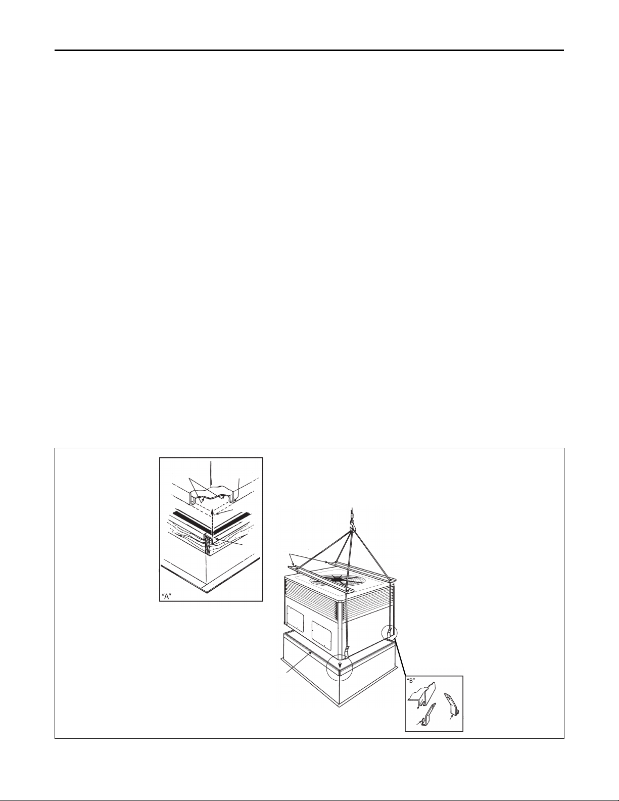
Base of unit
rest on top of
curb rails
Drip lip on
perimeter of
unit
Spreader Bars
Gasket Seal
Drip Lip
Dimple
BAYLIFT002A
Lifting Lugs
UUnniitt IInnssttaallllaattiioonn
9. The unit should not be exposed to direct roof water
runoff.
10. Flexible duct connectors must be of a flame
retardant material. All duct work outside of the
structure must be insulated and weatherproofed in
accordance with local codes.
11. Access and service clearances for the unit must be
given careful consideration when locating the duct
entrance openings.“ Determine Unit
Clearances,” p. 8 provide unit dimensions.
12. Continue with the following installation sections to
complete the installation: Ductwork, Filter, and
Electrical Wiring.
Rooftop Installation — No Curb/ Frame
For roof top applications using field fabricated ducts
and sleeper rails rather than a curb or frame, use the
following procedure:
1. Locate and secure the sleeper rails to the roof by
bolting (three (3) rails required). One on each end to
support the edges of the unit and one across the
center of the unit. The center rail must run inside
both drip lips. Vibration isolators should be
installed, adjust as necessary for your sleeper rails.
The isolators must be placed on base pan, not drip
lip. Add flashing as required. Flashing must
conform to local building codes.
2. Prepare the hole in the roof in advance of installing
the unit.
3. Secure the horizontal or down airflow ducts to the
roof. Refer to the previous Convert from Horizontal
Airflow to Down Airflow section if conversion is
needed.
4. All fabricated outdoor ducts should be as short as
possible.
5. Place the unit on the rails.
6. The unit must be mounted level for proper drainage
of water through the holes in the base pan.
7. Secure the unit to the rails.
8. Insulate any ductwork outside of the structure with
at least two (2) inches of insulation and then
weatherproof. There must be a weatherproof seal
where the duct enters the structure.
9. No exposure to direct roof water runoff.
10. Flexible duct connectors must be of a flame
retardant material. All duct work outside of the
structure must be insulated and weatherproofed in
accordance with local codes.
11. Access and service clearances for the unit must be
given careful consideration when locating the duct
entrance openings. “ Determine Unit
Clearances,” p. 8 provide unit dimensions.
12. Continue with the following installation sections:
Ductwork, Filter and Electrical Wiring.
Table 4. Lifting and Rigging
18-EB40D1-1A-EN
15
Page 16
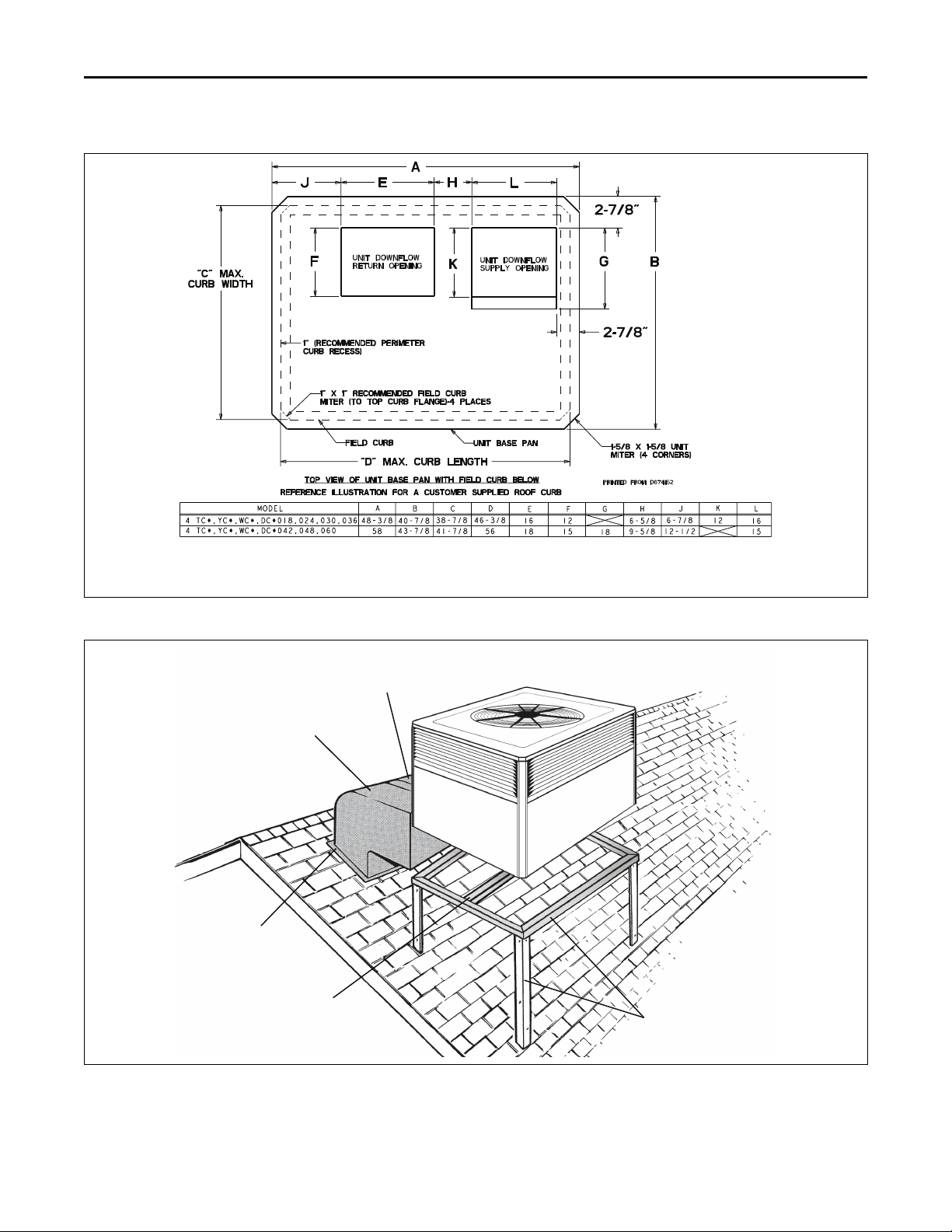
Supply Air
Return Air
Roof Flashing
Channel Iron Center
Support (Center Support
required on all frame
applications).
Angle Iron Frame
UUnniitt IInnssttaallllaattiioonn
Table 5. Curb Dimensions
This drawing was prepared by the manufacturer in order to provide detail regarding job layout only. This drawing is not intended to be used as a
basis to construct, build or modify the item depicted in the drawing. The manufacturer is not responsible for the unauthorized use of this
drawing and expressly disclaims any liability for damages resulting from such unauthorized use.
Table 6. Typical Rooftop Horizontal Airflow Application with Frame
16
18-EB40D1-1A-EN
Page 17
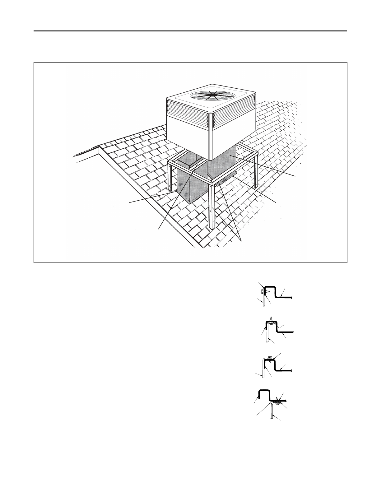
Table 7. Typical Rooftop Down Airflow Application with Frame
Return Air
Roof Flashing
Channel Iron Center Support
(center support required on all
frame applications).
Angle Iron Frame
Roof
Flashing
Supply
Air
FIELD DUCT
UNIT DUCT
FLANGE
UNIT BASE
AIR PROOF
THIS SEAM
FIELD DUCT
UNIT DUCT
FLANGE
UNIT BASE
AIR PROOF
THIS SEAM
FIELD
DUCT
UNIT DUCT FLANGE
UNIT BASE
AIR PROOF
THIS SEAM
FIELD DUCT
UNIT DUCT
FLANGE
UNIT BASE
NOT RECOMMENDED
WATERPROOF SEAM
WITH BUTYL OR
SILICONE
UUnniitt IInnssttaallllaattiioonn
Ductwork Installation
Attaching Downflow Ductwork to Roof Curb
Supply and return air flanges are provided on the roof
curb for easy duct installation. All ductwork must be
run and attached to the curb before the unit is set into
place.
Attaching Downflow Ductwork to Roof Frame
Follow these guidelines for ductwork construction:
Connections to the unit should be made with three (3)
inch canvas connectors to minimize noise and vibration
transmission.
Elbows with turning vanes or splitters are
recommended to minimize air noise and resistance.
The first elbow in the ductwork leaving the unit should
be no closer than two (2) feet from the unit, to minimize
noise and resistance.
To prevent leaking, do not attach the ductwork to the
bottom of the unit base. Refer to the bottom example in
the figure below.
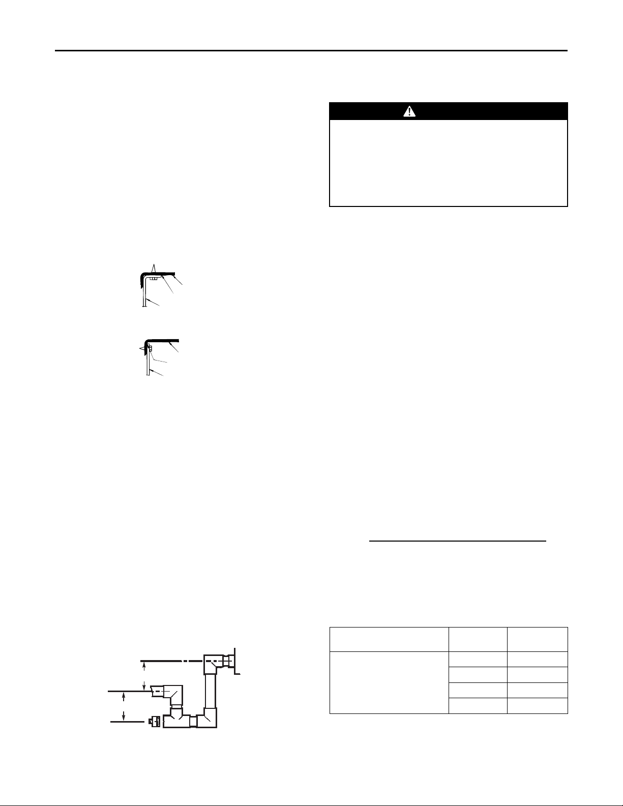
Figure 3. Attaching Down Airflow Ductwork
18-EB40D1-1A-EN
17
Page 18
FIELD DUCT
UNIT EXTERIOR
WEATHERPROOF
THIS SEAM
FIELD DUCT
UNIT EXTERIOR
WEATHERPROOF
THIS SEAM
3
/4" PVC OR COPPER
TUBING AND FITTINGS
1-1/2" MIN.
1-1/2" MIN.
Furnace Input in BTUH
Gas Heat Contne in BTU/Cu. Ft. X Multiplier
CFH =
UUnniitt IInnssttaallllaattiioonn
Attaching Horizontal Ductwork to Unit
All conditioned air ductwork should be insulated to
minimize heating and cooling duct losses. Use a
minimum of two (2) inches of insulation with a vapor
barrier. The outside ductwork must be weatherproofed
between the unit and the building.
When attaching ductwork to a horizontal unit, provide a
flexible watertight connection to prevent noise
transmission from the unit to the ducts. The flexible
connection mmuusstt be indoors and made out of heavy
canvas.
NNoottee:: Do not draw the canvas taut between the solid
ducts.
Figure 4. Attaching Horizontal Airflow Ductwork
Condensate Drain Piping
A 3/4-inch female NPT condensate drain connection is
provided on the evaporator access panel end of the
unit. Provide a trap and fill it with water before starting
the unit to avoid air from being drawn through. Follow
local codes and standard piping practices when
running the drain line. Pitch the line downward away
from the unit. Avoid long horizontal runs. See Figure
5, p. 18.
NNoottee:: Do not use reducing fittings in the drain lines.
The condensate drain must be:
• Made of 3/4” pipe size
• Pitched 1/4” per foot to provide free drainage to
convenient drain system
• Trapped
• Must be connected to a closed drain system unless
the trap is properly vented
Figure 5. Typical Condensate Drain Piping
18
Gas Piping Installation
WWAARRNNIINNGG
FFIIRREE OORR EEXXPPLLOOSSIIOONN HHAAZZAARRDD!!
FFaaiilluurree ttoo ffoollllooww tthhee ssaaffeettyy wwaarrnniinngg eexxaaccttllyy ccoouulldd
rreessuulltt iinn sseerriioouuss iinnjjuurryy,, ddeeaatthh,, oorr pprrooppeerrttyy
ddaammaaggee..
UUssee aa ccoommmmeerrcciiaallllyy aavvaaiillaabbllee ssooaapp ssoolluuttiioonn mmaaddee
ssppeecciiffiiccaallllyy ffoorr tthhee ddeetteeccttiioonn ooff lleeaakkss ttoo cchheecckk aallll
ccoonnnneeccttiioonnss..
IImmppoorrttaanntt:: Before making the gas pipe connection,
give serious consideration to providing the
clearance necessary to remove the access
panels on the unit (e.g., economizer and
filter access panels).
NNoottee:: In the absence of local codes, the installation
must conform with American National Standard–
Z223.1–National Fuel Gas Code, Latest Revision.
The available gas supply must agree with the required
gas supply marked on the unit nameplate. Minimum
permissible gas supply pressure for purpose of input
adjustment must be at least 7.0 in. w. c. (inches water
column) for natural gas and 11 in. w. c. for LP Gas.
PPiippee DDeelliivveerryy SScchheedduullee
NNoottee:: The following procedure and tables apply to
Natural Gas oonnllyy.
1. Obtain from the gas company the heating value and
specific gravity of the gas delivered.
2. Determine the exact length of pipe needed.
3. Read BTUH input nameplate on the furnace.
4. Use the multiplier opposite the specific gravity of
the gas given in Multiplier Table and insert in the
following formula:
5. Use the Natural Gas Only table and select the pipe
length nearest to calculated size.
6. Follow this line vertically down to the exact CFH
found in Step 4 above or the next highest value.
7. Read horizontally to the left of this column for the
required pipe size diameter.
Table 8. Specific Gravity Multiplier
SPECIFIC
GRAVITY
.50 1.10
MULTIPLIERS TO BE USED
WHEN THE SPECIFIC GRAVITY
OF THE GAS IS OTHER THAN
0.060
.55 1.04
.60 1.00
.65 .962
NNoottee:: If this is an LP Gas application, consult your LP
Gas supplier for pipe sizes and deliveries.
MULTIPLIER
18-EB40D1-1A-EN
Page 19

DEALER INSTALLED
GROUND UNION
1/8" N.P.T.PLUGGED
ACCESS FOR TEST
GAUGE CONNECTION
FROM
GAS SUPPLY
FIELD SUPPLIED MAIN
GAS VALVE, MUST BE
INSTALLED BY DEALER
OUTSIDE OF UNIT.
UNIT
TO MAIN
CONTROL
VALVE
6"
MIN
DRIP LEG
(6" MIN)
UUnniitt IInnssttaallllaattiioonn
Table 9. Natural Gas Only
TABLE OF CUBIC FEET PER HOUR OF GAS FOR VARIOUS
PIPE
SIZE
(inch)
1–1/4
THIS TABLE IS BASED ON PRESSURE DROP OF 0.3 INCH W.C.
AND 0.6 SP.GR. GAS
GGaass PPrreessssuurree SSeett--uupp PPrreeccaauuttiioonnss
IImmppoorrttaanntt:: Do not connect gas piping to the unit until a
The furnace must be isolated from the gas supply
piping system by closing its individual manual shut-off
valve during any pressure testing of the gas supply
piping system at test pressures less than or equal to 1/2
psig (3.48 kPa).
GGaass SSuuppppllyy LLiinnee PPrreessssuurree
Before connecting the unit to the gas supply line, be
sure to determine the gas pressure in the line.
If the gas supply pressure is excessive (above 14 inches
water column or 1/2 psig), install a pressure regulator
either at the supply source or in the branch circuit
serving the unit. Once the regulator is installed, set it to
provide a pressure of 7 inches water column with the
unit operating and no greater than 14 inches water
column with the unit not firing.
NNoottee:: Gas pressure in excess of 14 inches water
If the supply line pressure is below the minimum
supply pressure indicated on the unit nameplate,
contact the gas supply company.
Follow these steps to complete the installation of the
unit gas piping. See Table 10, p. 19.
NNoottee:: The shut-off gas cock must be installed outside
18-EB40D1-1A-EN
PIPE SIZES AND LENGTHS
10 20 30 40 50 60 70
1/2
3/4
1 520 350 285 245 215 195 180
132 92 73 63 56 50 46
278 190 152 130 115 105 96
1050 730 590 520 440 400 370
line pressure test has been completed. This
unit should never be exposed to gas line
pressure in excess of 14 inches water
column (1/2 PSIG). The furnace and its
equipment shutoff valve must be
disconnected from the gas supply piping
system during any pressure testing of that
system at test pressures in excess of 1/2
psi.
column (1/2 psig) may damage the regulator,
while improper regulation may result at
pressures lower than 5.5 inches water column at
the unit inlet.
of the unit and should meet the specifications of
all applicable national and local codes.
Table 10. Gas Pipe
NNoottee:: The shut-off gas cock must be installed outside
of the unit and should meet the specifications of
all applicable national and local code.
1. Install a ground union joint downstream of the
shut-off cock. This joint must also be installed
outside of the unit.
2. Install a drip leg at least six (6) inches in depth next
to the union as shown in . This drip leg is required
to collect any sediment that may be deposited in
the line.
3. Before connecting the piping circuit to the unit,
bleed the air from the supply line and then cap or
plug the line and test the pressure at the tapped
shut-off cock. The pressure reading should not
exceed 13.8 inches water column.
4. Using an appropriate backup wrench on the gas
valve inlet boss, connect the gas piping to the unit.
Check the completed piping for leaks using a soap
and water solution or the equivalent.
5. After installation of the gas pipe in the unit, the pipe
opening should be closed with the filler/barrier plug
provided.
VVeerriiffyy MMaanniiffoolldd PPrreessssuurree
Check the manifold pressure at the unit gas valve. Do
not exceed the recommended pressure shown on the
unit nameplate. See Figure 6, p. 20 for connections.
Refer to Manifold Pressure Check and Adjust in the
following Step 5-Unit Startup section if adjustment is
needed.
IInnppuutt CChheecckk aanndd AAddjjuussttmmeenntt
1. Make sure all gas appliances are off except the
furnace.
2. Clock the gas meter with the furnace operating
(determine the dial rating of the meter) for one
revolution.
3. Match the “Sec” column in the Gas Flow (in cfh)
Table 11, p. 20 with the time clocked.
4. Read the “Flow” column opposite the number of
seconds clocked.
19
Page 20
Regulator Cover Screw
(Adj. screw beneath
this screw)
Manual
On-Off
Switch
Inlet
Pressure
Tap
Vent Post
Outlet
Pressure Tap
REF. VIEW
(GAS VALVE)
Orifice
Burner
Manifold
Gas Valve
REF. VIEW
(3 Burners)
UUnniitt IInnssttaallllaattiioonn
5. Table 11, p. 20 lists values for a 2 cubic foot dial.
For 1, 1/2, or 5 Cu. Ft. dials use the following
conversions:
• 1 Cu. Ft. Dial Gas Flow CFH = Chart Flow
Reading / 2
• 1/2 Cu Ft. Dial Gas Flow CFH = Chart Flow
Reading / 4
• 5 Cu. Ft. Dial Gas Flow CFH = 10X Chart Flow
Reading / 4
6. Multiply the final figure by the heating value of the
gas obtained from the utility company and compare
to the nameplate rating. This must not exceed the
nameplate rating.
7. Changes can be made by adjusting the manifold
pressure.
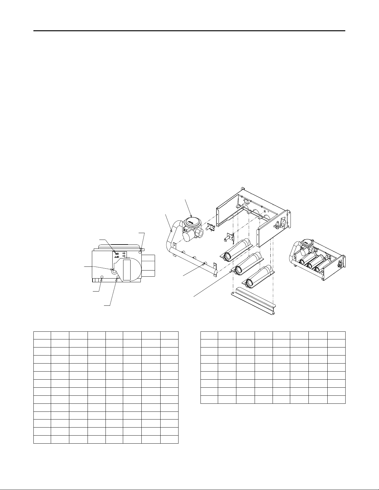
Figure 6. Burner and Valve
a. Attach a manifold pressure gauge to the Outlet
Pressure Tap.
b. Remove the cover screw on top of the gas valve
to access the manifold pressure adjustment
screw.
c. Turn the adjustment screw in to increase the
gas flow rate, and out to decrease the gas flow
rate using a 3/32" hex wrench or flat-head
screwdriver.
NNoottee:: For manifold pressures and orifice sizes for gas
with other BTU ratings, contact the local gas
utility. Manifold pressure should be 3.5 inches
water column (+ 0.1). Input for natural gas must
nnoott exceed the value shown on the rating plate.
Table 11. Gas Flow (in cfh)
Sec. Flow Sec. Flow Sec. Flow Sec. Flow
8 900 29 248 50 144 82 88
9 800 30 240 51 141 84 86
10 720 31 232 52 138 86 84
11 655 32 225 53 136 88 82
12 600 33 218 54 133 90 80
13 555 34 212 55 131 92 78
14 514 35 206 56 129 94 76
15 480 36 200 57 126 96 75
16 450 37 195 58 124 98 73
17 424 38 189 59 122 100 72
18 400 39 185 60 120 104 69
19 379 40 180 62 116 108 67
20 360 41 176 64 112 112 64
20
Table 11. Gas Flow (in cfh) (continued)
Sec. Flow Sec. Flow Sec. Flow Sec. Flow
21 343 42 172 66 109 116 62
22 327 43 167 68 106 120 60
23 313 44 164 70 103 124 58
24 300 45 160 72 100 128 56
25 288 46 157 74 97 132 54
26 277 47 153 76 95 136 53
27 267 48 150 78 92 140 51
28 257 49 147 80 90 144 50
18-EB40D1-1A-EN
Page 21
UUnniitt IInnssttaallllaattiioonn
HHiigghh AAllttiittuuddee IInnssttaallllaattiioonn
Input ratings (BTUH) of these furnaces are based on
sea level operation and should not be changed at
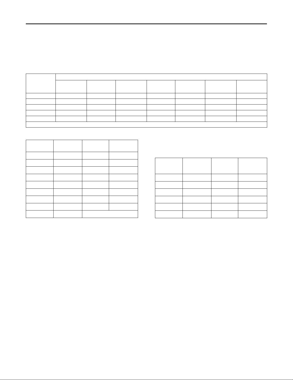
2000 to 8000 feet elevation, then change the burner
orifices to the size listed in Table 12, p. 21. Refer to
Table 13, p. 21 for orifice part numbers.
elevations up to 2000 ft. If the unit installation is from
Table 12. Orifice Twist Drill Size
Orifice Twist
Drill Size if
Installed at
Sea Level
32 33 34 35 35 36 36 37
33 35 35 36 36 37 38 38
37 38 39 39 40 41 42 42
49 50 50 50 51 51 51 52
52 52 53 53 53 53 53 54
2000 3000 4000 5000 6000 7000 8000
Table 13. Orifice Part Numbers
Drill Size
32 ORF01307 41 ORF01413
33 ORF0134 42 ORF01410
34 ORF01335 49 ORF01333
35 ORF01407 50 ORF01332
36 ORF01408 51 ORF01336
37 ORF01406 52 ORF01331
38 ORF01306 53 ORF01411
39 ORF01409 54 ORF01412
40 ORF01336
Part
Number
Air Filter Installation
Altitude Above Sea Level and Orifice Change Required for that Elevation
From National Fuel Gas Code — Table F-4
Affix the filter label supplied with the unit adjacent to
the filter area. Refer to Table 14, p. 21 to determine
filter size.
Drill Size
Part
Number
Table 14. Determine Filter Size
Unit
YC~4024A 800 2.67 0.08
YC~4030A 1000 3.33 0.08
YC~4036A 1200 4.00 0.08
YC~4042A 1400 4.67 0.08
YC~4048A 1600 5.33 0.08
YC~4060A 2000 6.67 0.08
(a)
Filters must be installed in the return air system. The above square
footages are based on 300 F.P.M. face velocity. If permanent filters
are used, size per mfg. Recommendation with clear resistance of
0.05" WC.
Nominal
CFM
Filter Size
(Sq Ft)
The packaged unit requires an air filter. The unit does
not come with a factory installed filter rack in it,
however, two filter frame accessories are offered that
IImmppoorrttaanntt:: Air filters and media wheels or plates shall
meet the test requirements in UL 900.
will allow the installation of a filter within the unit,
BAYFLTR101 & BAYFLTR201. Otherwise a field
supplied filter rack must be installed by the installer in
the return duct work.
(a)
Filter
Resistance
(W.C.)
18-EB40D1-1A-EN
21
Page 22
Run power supply lines through weather-tight
conduit and secure to unit with strain relief.
Unit Ground
Lug
Contactor
UUnniitt IInnssttaallllaattiioonn
Electrical Wiring
WWAARRNNIINNGG
IINNSSTTAALLLLAATTIIOONN WWAARRNNIINNGG —— HHIIGGHH
VVOOLLTTAAGGEE MMOOVVIINNGG PPAARRTTSS!!
FFaaiilluurree ttoo ffoollllooww tthhiiss WWaarrnniinngg ccoouulldd rreessuulltt iinn
pprrooppeerrttyy ddaammaaggee,, sseevveerree ppeerrssoonnaall iinnjjuurryy,, oorr
ddeeaatthh..
BBooddiillyy iinnjjuurryy ccaann rreessuulltt ffrroomm hhiigghh vvoollttaaggee
eelleeccttrriiccaall ccoommppoonneennttss,, ffaasstt mmoovviinngg ffaannss,, aanndd
ccoommbbuussttiibbllee ggaass.. FFoorr pprrootteeccttiioonn ffrroomm tthheessee
iinnhheerreenntt hhaazzaarrddss dduurriinngg iinnssttaallllaattiioonn aanndd sseerrvviicciinngg,,
tthhee mmaaiinn ggaass vvaallvvee mmuusstt bbee ttuurrnneedd ooffff aanndd tthhee
eelleeccttrriiccaall ssuuppppllyy mmuusstt bbee ddiissccoonnnneecctteedd.. IIff
ooppeerraattiinngg cchheecckkss mmuusstt bbee ppeerrffoorrmmeedd wwiitthh tthhee uunniitt
ooppeerraattiinngg,, iitt iiss tthhee tteecchhnniicciiaann’’ss rreessppoonnssiibbiilliittyy ttoo
rreeccooggnniizzee tthheessee hhaazzaarrddss aanndd pprroocceeeedd ssaaffeellyy..
NNoottee:: This unit is factory wired for 230V. See wiring
diagram for 208V conversion.
EElleeccttrriiccaall CCoonnnneeccttiioonnss
Electrical wiring and grounding must be installed in
accordance with local codes or, in the absence of local
codes, with the National Electrical Code ANSI/NFPA 70,
Latest Revision.
EElleeccttrriiccaall PPoowweerr
It is important that proper electrical power be available
for the unit. Voltage variation should remain within the
limits stamped on the unit nameplate.
DDiissccoonnnneecctt SSwwiittcchh
Provide an approved weatherproof disconnect within
close proximity and wwiitthhiinn ssiigghhtt ooff tthhee uunniitt..If
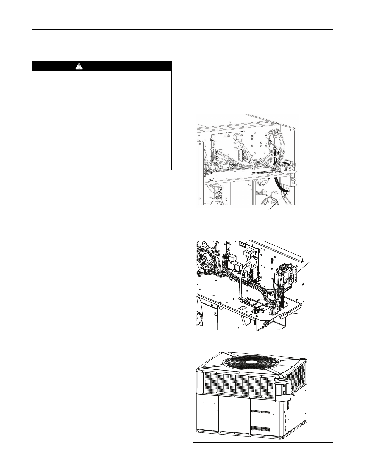
disconnect must be mounted to the cabinet, the
location shown in Table 17, p. 22 should be the only
one considered.
OOvveerr CCuurrrreenntt PPrrootteeccttiioonn
The branch circuit feeding the unit must be protected
as shown on the unit's rating plate.
PPoowweerr WWiirriinngg
The power supply lines must be run in weather-tight
conduit to the disconnect and into the side of the unit
control box. Provide strain relief for all conduit with
suitable connectors.
Provide flexible conduit supports whenever vibration
transmission may cause a noise problem within the
building structure.
1. Remove the Control/Heat access panel. Pass the
power wires through the Power Entry hole in the
end of the unit. See Table 15, p. 22.
2. Connect the high voltage wires to the appropriate
contactor terminals. Single phase units use a two
(2) pole contactor and three phase units use three
(3) pole contactor. Connect the ground to the
ground lug on the chassis. See Table 17, p. 22.
Ensure all connections are tight.
GGRROOUUNNDDIINNGG:: TTHHEE UUNNIITT MMUUSSTT BBEE EELLEECCTTRRIICCAALLLLYY
GGRROOUUNNDDEEDD IINN AACCCCOORRDDAANNCCEE WWIITTHH LLOOCCAALL CCOODDEESS
OORR TTHHEE NNAATTIIOONNAALL EELLEECCTTRRIICC CCOODDEE..
NNoottee:: Unit must be grounded for ignitor to operate
properly. Gas pipe to unit is not an adequate
ground. Ground the unit internally as provided.
See wiring diagram for location in.
Table 15. Power Wiring
Table 16. Power Connections
Table 17. Mounted Disconnect Location
22
18-EB40D1-1A-EN
Page 23
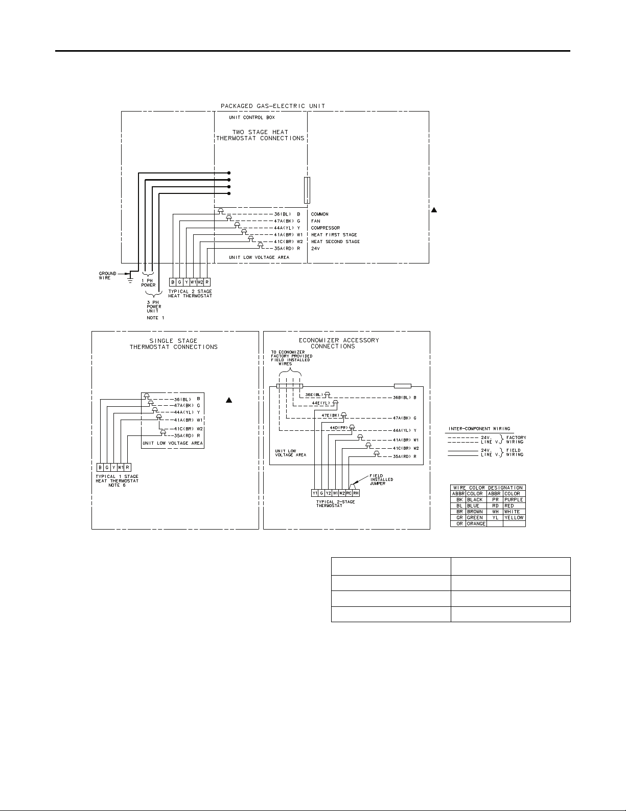
Figure 7. 4YCC4— Field Wiring Diagram
FAN (GR)
(CONSTANT CIRCULATION)
COMMON
CONTACTOR/COMPRESSOR/FAN
HEAT FIRST STAGE (WH)
HEAT SECOND STAGE (WH)
24V
NOTES:
1. FUSED DISCONNECT SIZE, POWER
WIRING AND GROUNDING OF
EQUIPMENT MUST COMPLY WITH
CODES.
2. BE SURE POWER SUPPLY AGREES
WITH EQUIPMENT AND HEATER
NAMEPLATE.
3. LOW VOLTAGE WIRING TO BE
18 AWG MINIMUM CONDUCTOR.
4. SEE UNIT DIAGRAM FOR
ELECTRICAL CONNECTION DETAILS.
5. THE GAS ELECTRIC UNIT WILL
PROVIDE CONSTANT CIRCULATION
REGARDLESS OF COOLING OR
HEATING STATUS WITH A ‘G’ SIGNAL
ONLY FROM THE THERMOSTAT.
6. FOR SINGLE STAGE THERMOSTATS,
JUMPER W1 AND W2 TOGETHER.
SECOND STAGE HEAT WILL BEGIN
10 MINUTES AFTER FIRST STAGE.
DWG. C757192REVA
UUnniitt IInnssttaallllaattiioonn
CCoonnttrrooll WWiirriinngg ((CCllaassss IIII))
Low voltage control wiring should not be run in conduit
with power wiring unless Class 1 wire of proper voltage
rating is used. Route the thermostat cable or equivalent
single leads of No. 18 AWG colored wire from the
thermostat subbase terminals through the rubber
grommet on the unit. See Unit Clearance Graphics for
the control entry (24V Entry) location. Make
connections as shown on the unit wiring diagram.
Do not short thermostat wires since this will damage
the control transformer.
Refer to Table 18, p. 23 for recommended wire sizes
and lengths for installing the unit thermostat. The total
resistance of these low voltage wires must not exceed
one (1) ohm. Any resistance in excess of 1 ohm may
cause the control to malfunction because of the
excessive voltage drop.
Table 18. Thermostat Wire Size and Max. Length
Wire Size
Maximum Length
18 75
16 125
14 200
TThheerrmmoossttaatt HHeeaatt AAnnttiicciippaattoorr
Set the heat anticipator of the thermostat to equal the
amperage draw of the gas valve
IImmppoorrttaanntt:: UUppoonn ccoommpplleettiioonn ooff wwiirriinngg,, cchheecckk aallll
eelleeccttrriiccaall ccoonnnneeccttiioonnss,, iinncclluuddiinngg ffaaccttoorryy
wwiirriinngg wwiitthhiinn tthhee uunniitt..
Make sure all connections are tight. Replace and secure
all electrical box covers and access panels before
leaving the unit or turning on the power to the unit.
18-EB40D1-1A-EN
23
Page 24

Unit Startup
Pre-Start Quick Checklist
☐ Is the unit properly located and level with the
proper clearances? See “ Determine Unit
Clearances,” p. 8.
☐ Is the duct work correctly sized, run, taped,
insulated, and weatherproofed with proper unit
arrangement as shown in the ductwork installation
section?
☐ Is the condensate line properly sized, run, trapped,
and pitched and shown in the Condensate Drain
Piping section?
☐ Is the gas piping correctly sized, run, trapped, and
purged of air? See Gas Piping Installation section.
☐ Is the filter of the correct size and quantity? Is it
clean and in place? See Air Filter Installation
section.
☐ Is the wiring properly sized and run according to the
unit wiring diagram?
☐ Are all the wiring connections, including those in
the unit tight?
☐ Has the unit been properly grounded and fused
with the recommended fuse size?
☐ Is the thermostat well located, level, and correctly
wired? See Electrical Wiring section.
☐ Have the air conditioning systems been checked at
the service ports for charge and leak tested if
necessary?
☐ Do the condenser fan and indoor blower turn free
without rubbing and are they tight on the shafts?
☐ Has the indoor blower speed been determined and
the proper speed been set? To adjust the fan, see
the Indoor Fan Motor Speed Tap Setting section.
☐ Has all work been done in accordance with
applicable local and national codes?
☐ Are all covers and access panels in place to prevent
air loss and safety hazards?
Starting the Unit in Cooling Mode
NNoottee:: See the section on Sequence of Operation for a
description of the cooling operating sequence.
To start the unit in the cooling mode, set the
thermostat system switch to COOL and move the
thermostat COOL indicator to a setting below room
temperature. The condenser fan motor, compressor
and evaporator fan motor will operate automatically.
OOppeerraattiinngg PPrreessssuurree CChheecckkss
After the unit has operated in the cooling mode for a
short period of time, install pressure gauges on the
gauge ports of the discharge and suction line valves
(behind the Compressor access panel). Check the
suction and discharge pressures and compare them to
the normal operating pressures provided in the unit’s
SERVICE FACTS.
NNoottee:: Do not use the PRESSURE CURVES from the
unit's SERVICE FACTS to determine the unit
refrigerant charge. The correct charge is shown
on the unit nameplate. To charge the system
accurately, weigh in the charge according to the
unit nameplate and check subcooling against the
Subcooling Charging Table in the SERVICE
FACTS.
VVoollttaaggee CChheecckk
With the compressor operating, check the line voltage
at the unit (contactor is located behind the Control/Heat
access panel). The voltage should be within the range
shown on the unit nameplate. If low voltage is
encountered, check the size and length of the supply
line from the main disconnect to the unit. The line may
be undersized for the length of the run.
CCoooolliinngg SShhuutt DDoowwnn
At the thermostat, place the system selector to the OFF
position or reset the thermostat to a setting above
room temperature.
IImmppoorrttaanntt:: De-energize the main power disconnect
ONLY when servicing the unit. Power may
be required to keep the heat pump
compressor warm and to boil off
refrigerant in the compressor.
Starting the Unit in Heating Mode
NNoottee:: See the section on Sequence of Operation for a
description of the heat pump heating operating
sequence.
These units are equipped with a solid-state ignition
control that lights the burners each time the thermostat
calls for heat. The burners are extinquished during the
OFF cycle. To start the gas heating section of the unit:
1. Check that all grills and registers are open and all
unit access panels are closed before start-up.
24
18-EB40D1-1A-EN
Page 25

UUnniitt SSttaarrttuupp
2. Purge the gas supply line of air by opening the
union ahead (upstream) of the unit. When the odor
of gas is detected, retighten the union and wait five
(5) minutes before proceeding.
3. Be sure the thermostat is at its lowest setting and
the power to the unit is off.
a. Turn the main shut-off valve on the gas supply
line to ON.
b. Turn the thermostat to the highest setting in the
heating cycle.
4. Be sure the burner compartment access panel is in
place.
a. Turn on the electrical power to the unit.
b. Turn the thermostat to the highest setting in the
heating cycle.
5. As the thermostat calls for heat, the system cycles
as follows:
a. The combustion blower is energized.
b. The pressure switch is closed.
c. The gas valve opens and the ignitor lights the
burner.
d. Cycle the thermostat on and off a few times to
check out the control system and burner
operation characteristics.
NNoottee:: For manifold pressures and orifice sizes
for gas with other BTU ratings, contact
the local gas utility. Manifold pressure
should be 3.5 inches w.c. (+0.1). Input
must nnoott exceed the value shown on the
rating plate.
e. With the burner operating, check the manifold
pressure with a manometer.
6. Do not exceed recommended pressures. If the
manifold pressure needs adjustment, refer to
Manifold Pressure Check and Adjust in the
Maintenance section. With the burners operating,
check the manifold pressure with a manometer.
7. If necessary, adjust the unit to obtain an air
temperature rise with that specified on the unit
nameplate. To adjust, refer to the Indoor Fan Motor
Speed Adjustment in the Maintenance section.
NNoottee:: Blue smoke produced by the heat exchanger
during the initial burner firing is caused by a
thin film of oil on the surface of the heat
exchanger. This oil will burn off quickly.
8. Set the thermostat at the desired temperature
setting and the unit will function automatically.
Sequence of Operation
GGeenneerraall
Operation of the system cooling (and optional heating)
cycles is controlled by the setting of the system switch
on the room thermostat. Once the system switch is
placed either in the “HEAT” or “COOL” position, unit
operation is automatic. A fan switch on the thermostat
also provides for continuous operation of the
evaporator fan when desired. The fan switch “ON”
position provides continuous operation while the
“AUTO” position provides operation during the
heating or cooling cycles.
HHeeaattiinngg CCyyccllee
TThheerrmmoossttaatt ccaallll ffoorr hheeaatt
(R) and (W) thermostat contacts close signaling the
control module (IGN) to run its self-check routine. After
the control has verified that the pressure switch (PS)
contacts are open, the limit switch (TCO) contacts are
closed, and the flame rollout (RO) switch is closed, the
induced draft blower (CFM) will be energized.
After the induced draft blower (CFM) has come up to
speed, the control will verify that the pressure switch
(PS) contacts are closed and run the induced draft
blower for a 20 second pre-purge. The gas valve (GV) is
energized to permit gas flow and the spark ignitor (IP)
is energized. The flame detector (FD) confirms that
ignition has been achieved within the 7 second trial
period.
As the flame detector confirms that ignition has been
achieved the delay to indoor fan on period begins
timing and after approximately 45 seconds, the indoor
blower motor (IDM) will be energized and will continue
to run during the heating cycle
TThheerrmmoossttaatt ssaattiissffiieedd:
(R) and (W) contacts open signaling the control module
to close the gas valve and de-energize the induced draft
blower after approximately 5 seconds post-purge. The
indoor blower motor will continue to operate at the
current speed for 60 or 90 seconds (field selectable)
after the flames are extinguished.
CCoooolliinngg CCyyccllee
With the room thermostat system switch in the
"COOLING" position and the fan switch in the "AUTO"
position, the compressor contactor (CC) and the indoor
fan motor (IDM) are energized.
The energized compressor contactor (CC) completes
the circuit to the compressor (CPR) and a secondary
circuit to the outdoor fan motor (ODM). If the
compressor safety controls are closed, the compressor
(CPR) will operate with the outdoor fan motor (ODM).
The indoor fan motor (IDM) will operate. The
thermostat will continue to cycle the compressor and
fans to maintain the desired temperature.
With the thermostat fan switch in the "ON" position, the
indoor fan motor (IDM) will continue to run at constant
18-EB40D1-1A-EN
25
Page 26

UUnniitt SSttaarrttuupp
circulation of 40 – 50% airflow of selected tap
regardless of compressor and condenser fan operation.
SSaaffeettyy SSeeqquueenncceess
This product is equipped with safety devices to protect
against abnormal conditions.
The temperature limit switch (TCO) is located on the
blower barrier, and can be accessed through the
blower compartment. This automatic reset device
protects against excessive leaving air temperature. If
this device opens, the gas valve is immediately closed
and will not permit operation until the limit switch
closes.
The rollout switch (RO) is located in the gas
compartment near the inlet of the burners. This is a
manual reset device designed to protect against any
form of flame rollout. If this device is opened the gas
valve is immediately de-energized and the control
(IGN) will lockout the system. The rollout switch (RO)
must be reset before operation is allowed to continue.
The pressure switch (PS) is located in the upper right
side of the gas compartment. This automatic device
assures adequate combustion air pressure. If pressure
against the induced draft blower outlet becomes
excessive, the pressure switch will react and shut off
the gas valve, until acceptable combustion pressure is
again available.
If the control (IGN) does not sense flame within the first
trial for ignition period, the gas valve will be deenergized. The control (IGN) will initiate a 60 seconds
interpurge. Following the interpurge, the control will
perform a second ignition attempt. If the second try is
not successful, the control will start another 60 second
interpurge. After the interpurge, a third attempt will be
tried. If the third try is not successful, the control will
lock out.
If loss of flame occurs during a heating cycle, the
control (IGN) will close the gas valve and cycle through
the ignition trial as stated above.
If control lock out occurs, the control (IGN) will retry a
complete ignition sequence in 1 hour.
The control (IGN) can be reset by removing power to
the unit or by turning the thermostat from “on” to “off”
for approximately three seconds, then back “on”.
Final Installation Checklist
☐ Does the unit run and operate as described in the
section on "Sequence of Operation" in response to
the room thermostat?
☐ Are the condenser fan and indoor blower operating
correctly with proper rotation and without undue
noise?
☐ Is the compressor operating correctly and has the
system been checked with a charging chart?
☐ Has the voltage and running current been checked
to deter mine if it is within limits?
☐ Has the thermostat been checked for calibration
and the air discharge grilles adjusted to balance the
system?
☐ Has the ductwork been checked for air leaks and
condensation?
☐ Has the furnace manifold pressure been checked
and adjusted if necessary?
☐ Has the heating air temperature rise been checked?
☐ Has the unit been checked for tubing and sheet
metal rattles? Are there any other unusual noises to
be checked?
☐ Are all covers and panels in place and properly
fastened?
☐ Has the owner been instructed on the proper
operation and maintenance of the unit? Be sure to
leave this manual with the owner.
Maintenance
Service Maintenance
Service maintenance should be performed by qualified
service personnel.
CCoooolliinngg SSeeaassoonn
To keep the unit operating safely and efficiently, the
manufacturer recommends that a qualified service
technician check the entire system at least once each
year or more often if needed. The service technician
should examine these areas of the unit:
• filters (for cleaning or replacement)
• motors and drive system components
• economizer gaskets (for possible replacement)
• safety controls (for mechanical cleaning)
• electrical components and wiring (for possible
replacement and connection tightness)
• condensate drain (for proper sealing and cleaning)
• unit duct connections (to see that they are
physically sound and sealed to the unit casing)
• unit mounting support (for structural integrity)
• the unit (for obvious unit deterioration)
HHeeaattiinngg SSeeaassoonn
Complete the following unit inspections and service
routines described at the beginning of each heating
season.
• Visually inspect the unit to ensure that the airflow
required for combustion and condenser coil is not
obstructed from the unit.
• Inspect the control panel wiring to verify that all
electrical connections are tight and that the wire
insulation is intact.
• Check the operation of the gas ignition system as
follows: Turn off the gas supply with the unit
operating to verify that the gas valve closes and
that a re-ignition cycle is initiated by the unit.
• Visually inspect the inside of the burners and the
26
18-EB40D1-1A-EN
Page 27

UUnniitt SSttaarrttuupp
burner ports for deposit buildup and corrosion.
Wipe and brush the inside of the burner and the
burner ports and then clean with a dry cloth. If the
deposit buildup or corrosion is excessive, replace
the burners.
FFlluuee HHoooodd aanndd CCoommbbuussttiioonn BBlloowweerr CClleeaanniinngg
NNoottee:: Never use combustible cleaning fluids on any
part of the furnace.
Before each heating season, the flue should be
inspected for signs of flaking rust and soot deposits.
DDiirrttyy fflluueess sshhoouulldd bbee cclleeaanneedd bbyy qquuaalliiffiieedd sseerrvviiccee
ppeerrssoonnnneell OONNLLYY using the following procedure:
1. Turn the comfort control to OOFFFF. Turn the main
power disconnect OOFFFF. Turn the manual gas valve
OOFFFF.
2. Remove the flue hood and the CONTROL/HEAT
access panel.
3. Remove the combustion blower assembly from the
flue box. Remove the flue box and the flue
restrictors.
4. Remove all wires from the gas valve while carefully
noting their locations.
5. Disconnect the gas supply line from the valve.
6. Remove the manifold retaining screws and pull the
burner-manifold assembly from the heat
exchanger.
7. Remove the inlet turbulators being careful not to
break or damage them.
8. Wipe the flue box and flue baffles clean with a
clean, dry cloth.
9. Replace all gaskets with new ones.
10. Replace all damaged or broken turbulators with
new ones.
11. Reassemble the unit by reversing Steps 2 through 7
above. Take care that all gaskets seat properly.
12. Check all wires for correct installation by referring
to the unit’s electrical wiring diagram in the
SERVICE FACTS.
13. Leak test all gas line connections with a soap and
water solution or the equivalent.
14. Re-install the CONTROL/HEAT access panels and
the flue hood.
15. Visually inspect the unit to ensure that the airflow
opening for combustion is not obstructed.
16. Follow “Unit Startup,” p. 24 to place the unit back
in service.
IInnddoooorr FFaann MMoottoorr ((IIDDMM)) SSppeeeedd TTaapp SSeettttiinngg
The 208/230 units are factory set to medium speed.
208/230 Volt Motor Tap Settings ()
High speed setting: On the IGN board:
1. Connect the "RD" wire to the "PARK" terminal.
2. Connect the (IDM) PR wire to the "BLOWER LOAD"
terminal.
Low speed setting: On the IGN board:
1. Connect the "RD" wire to the "BLOWER LOAD"
terminal.
2. Connect the (IDM) PR wire to the "PARK" terminal.
18-EB40D1-1A-EN
27
Page 28
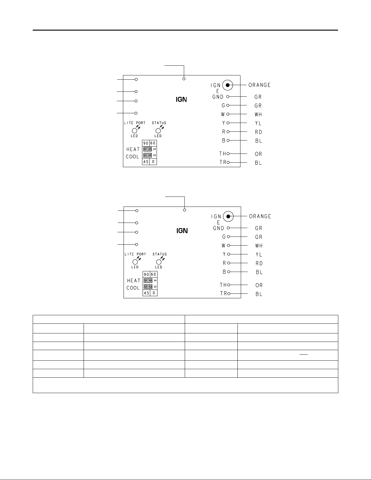
LOAD
BLOWER
LOAD
INDUCER
YL
(CC1) RD
RD
(IDM) PR
PARK
IN
IN
( CC1) RD
LOAD
BLOWER
LOAD
INDUCER
YL
(CC1) RD
RD
(IDM) PR
PARK
IN
IN
( CC1) RD
UUnniitt SSttaarrttuupp
Figure 8. 208/230 Volt Speed Taps
Table 19. IGN LED Diagnostic Indicators
Status LED
Steady OFF
Slow Flash Rate
Fast Flash Rate Not used 4 Flashes
Steady ON Normal, No Call for Heat
Fast Flash Rate: The LED will flash on for 1/4 second and off for 1/4 second.
Slow Flash Rate: The LED will flash on for 3/4 second, then off for 1/4 second.
The pause between groups of fast flashes is 3 seconds.
Check Power or Failed Board 2 Flashes
Normal, No Call for Heat
3 Flashes
5 Flashes
6 Flashes
7 Flashes
Liteport LED
System Lockout: Failed to detect or sustain
flame
Pressure switch problem detected
High Limit switch protection device open
Flame sensed and gas valve not energized or
flame sensed and no “W” signal.
Flame Rollout Switch open
Thermostat miswired; W! & W2
28
18-EB40D1-1A-EN
Page 29
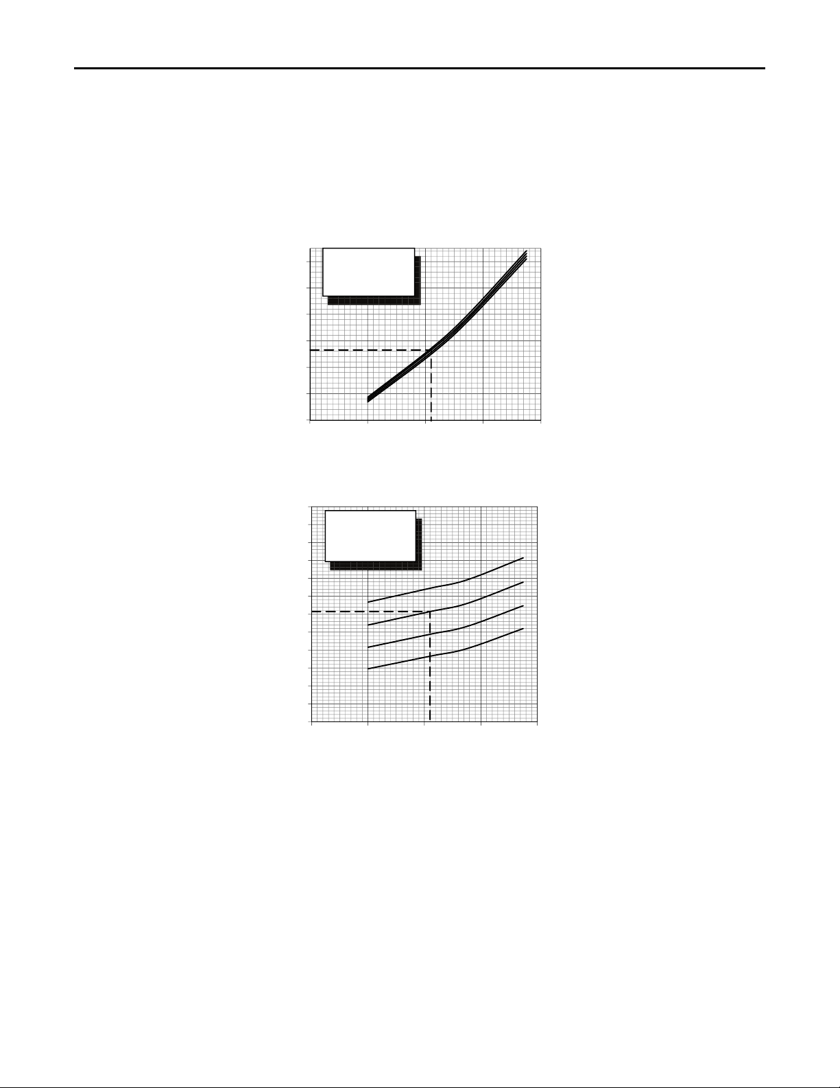
Pressure Curves
Cooling
Liquid PRESSURE (PSIG)
OUTDOOR TEMPERATURE (Degree F)
SUCTION PRESSURE (PSIG)
OUTDOOR TEMPERATURE (Degree F)
COOLING PERFORMANCE CAN BE CHECKED WHEN THE OUTDOOR TEMP IS ABOVE 65 DEG F.
TO CHECK COOLING PERFORMANCE, SELECT THE PROPER INDOOR CFM, ALLOW PRESSURES TO STABILIZE. MEASURE INDOOR WET BULB
TEMPERATURE, OUTDOOR TEMPERATURE, DISCHARGE AND SUCTION PRESSURES. ON THE PLOTS LOCATE OUTDOOR TEMPERATURE (1);
LOCATE INDOOR WET BULB (2); FIND INTERSECTION OF OD TEMP. & ID W.B. (3); READ LIQUID (4) OR SUCTION (5) PRESSURE IN LEFT COLUMN.
EXAMPLE: (1) OUTDOOR TEMP. 82 F.
(2) INDOOR WET BULB 67 F.
(3) AT INTERSECTION ACTUAL:
(4) DISCHARGE PRESSURE @ 800 CFM CFM IS 333 PSIG.
DISCHARGE PRESSURE SHOULD BE +/- 10 PSI OF CHART
(5) SUCTION PRESSURE @ 800 CFM CFM IS 141 PSIG.
SUCTION PRESSURE SHOULD BE +/- 3 PSIG OF CHART
200
250
300
350
400
450
500
40 60 80 100 120
110
115
120
125
130
135
140
145
150
155
160
165
170
40 60 80 100 120
(1)
(3)
(3)
(5)
(4)
(2)
INDOOR ENTERING
WET BULB CURVES
TOP TO BOTTOM
71, 67, 63 AND 59
DEG F.
110
115
120
125
130
135
140
145
150
155
160
165
170
40 60 80 100 120
(1)
(1)
(3)
(3)
(5)
(4)
(2)
INDOOR ENTERING
WET BULB CURVES
TOP TO BOTTOM
71, 67, 63 AND 59 DEG
INDOOR ENTERING
WET BULB CURVES
TOP TO BOTTOM
71, 67, 63 AND 59
DEG F.
Dwg. 4YCC4024E1
UUnniitt SSttaarrttuupp
Figure 9. Pressure Curve – 4YCC4024E1
18-EB40D1-1A-EN
29
Page 30
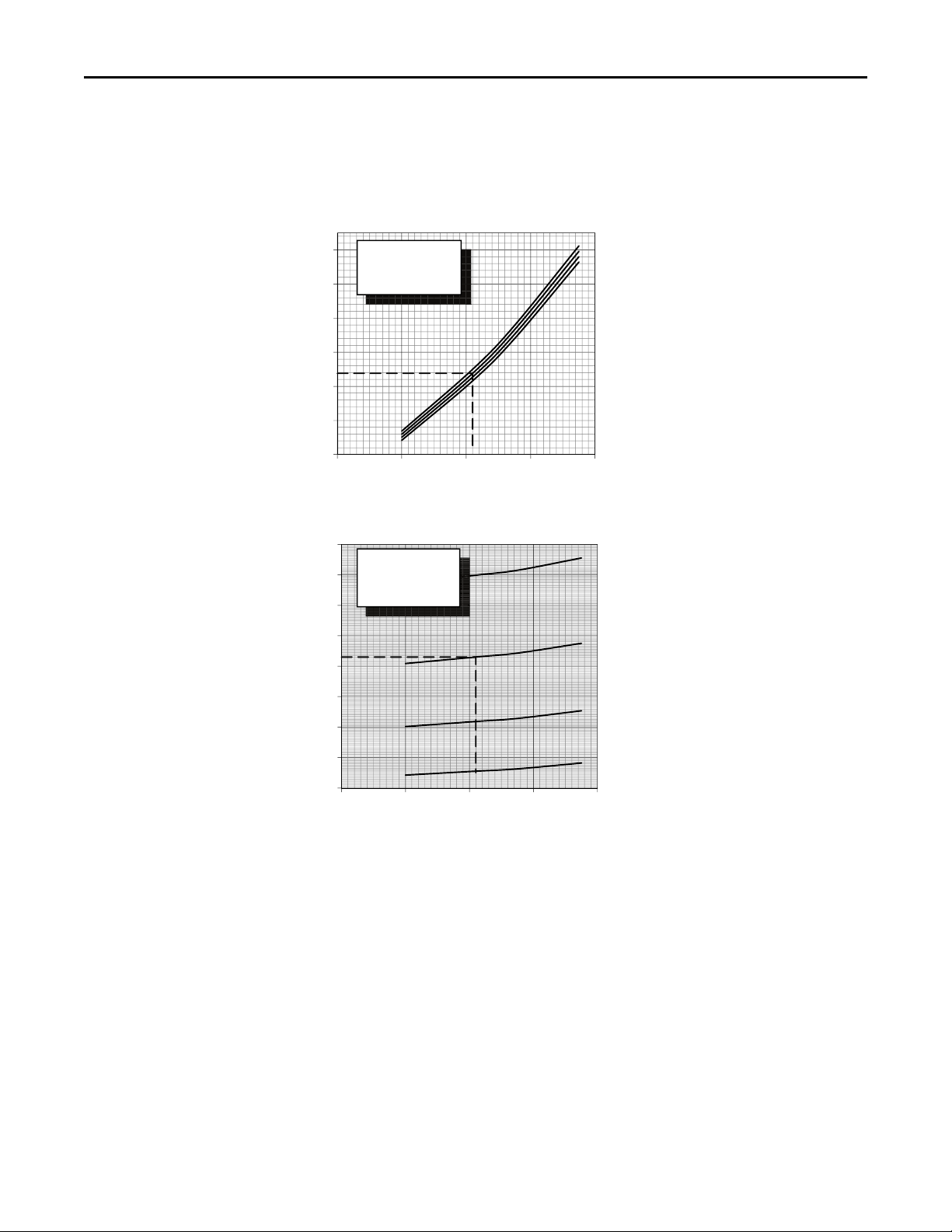
Liquid PRESSURE (PSIG)
OUTDOOR TEMPERATURE (Degree F)
SUCTION PRESSURE (PSIG)
OUTDOOR TEMPERATURE (Degree F)
COOLING PERFORMANCE CAN BE CHECKED WHEN THE OUTDOOR TEMP IS ABOVE 65 DEG F.
TO CHECK COOLING PERFORMANCE, SELECT THE PROPER INDOOR CFM, ALLOW PRESSURES TO STABILIZE. MEASURE INDOOR WET BULB
TEMPERATURE, OUTDOOR TEMPERATURE, DISCHARGE AND SUCTION PRESSURES. ON THE PLOTS LOCATE OUTDOOR TEMPERATURE (1);
LOCATE INDOOR WET BULB (2); FIND INTERSECTION OF OD TEMP. & ID W.B. (3); READ LIQUID (4) OR SUCTION (5) PRESSURE IN LEFT COLUMN.
EXAMPLE: (1) OUTDOOR TEMP. 82 F.
(2) INDOOR WET BULB 67 F.
(3) AT INTERSECTION ACTUAL:
(4) DISCHARGE PRESSURE @ 900 CFM CFM IS 320 PSIG.
DISCHARGE PRESSURE SHOULD BE +/- 10 PSI OF CHART
(5) SUCTION PRESSURE @ 900 CFM CFM IS 136 PSIG.
SUCTION PRESSURE SHOULD BE +/- 3 PSIG OF CHART
50
70
90
110
130
150
170
190
210
40 60 80 100 120
200
250
300
350
400
450
500
40 60 80 100 120
(1)
(3)
(3)
(5)
(4)
(2)
(2)
INDOOR ENTERING
WET BULB CURVES
TOP TO BOTTOM
71, 67, 63 AND 59 DEG
INDOOR ENTERING
WET BULB CURVES
TOP TO BOTTOM
DEG F.
Dwg. 4YCC4030E1
Cooling
UUnniitt SSttaarrttuupp
Figure 10. Pressure Curve – 4YCC4030E1
30
18-EB40D1-1A-EN
Page 31
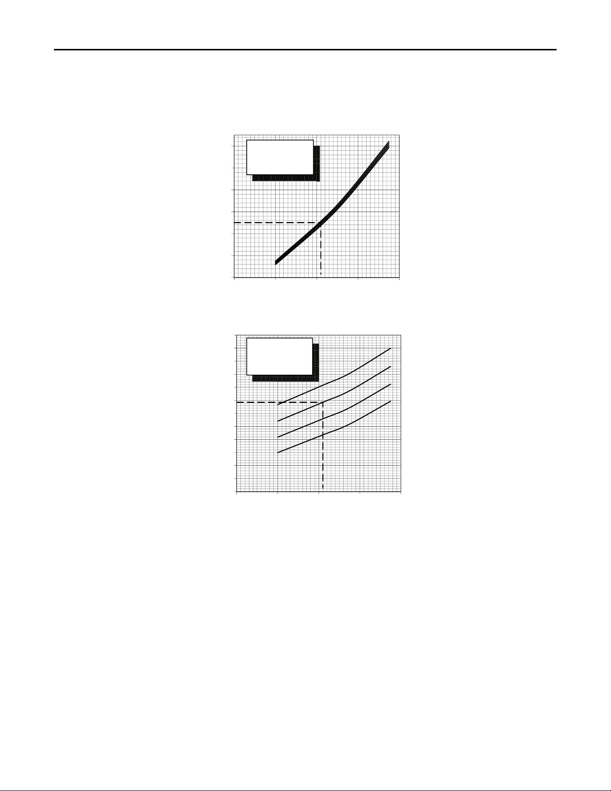
Figure 11. Pressure Curve – 4YCC4036E1
Liquid PRESSURE (PSIG)
OUTDOOR TEMPERATURE (Degree F)
SUCTION PRESSURE (PSIG)
OUTDOOR TEMPERATURE (Degree F)
COOLING PERFORMANCE CAN BE CHECKED WHEN THE OUTDOOR TEMP IS ABOVE 65 DEG F.
TO CHECK COOLING PERFORMANCE, SELECT THE PROPER INDOOR CFM, ALLOW PRESSURES TO STABILIZE. MEASURE INDOOR WET BULB
TEMPERATURE, OUTDOOR TEMPERATURE, DISCHARGE AND SUCTION PRESSURES. ON THE PLOTS LOCATE OUTDOOR TEMPERATURE (1);
LOCATE INDOOR WET BULB (2); FIND INTERSECTION OF OD TEMP. & ID W.B. (3); READ LIQUID (4) OR SUCTION (5) PRESSURE IN LEFT COLUMN.
EXAMPLE: (1) OUTDOOR TEMP. 82 F.
(2) INDOOR WET BULB 67 F.
(3) AT INTERSECTION ACTUAL:
(4) DISCHARGE PRESSURE @ 1200 CFM CFM IS 326 PSIG.
DISCHARGE PRESSURE SHOULD BE +/- 10 PSI OF CHART
(5) SUCTION PRESSURE @ 1200 CFM CFM IS 144 PSIG.
SUCTION PRESSURE SHOULD BE +/- 3 PSIG OF CHART
DWG.NO. 4YCC4036E1
110
115
120
125
130
135
140
145
150
155
160
165
170
40 60 80 100 120
200
250
300
350
400
450
500
40 60 80 100 120
(1)
(3)
(3)
(5)
(4)
(2)
(2)
INDOOR ENTERING
WET BULB CURVES
TOP TO BOTTOM
71, 67, 63 AND 59 DEG
INDOOR ENTERING
WET BULB CURVES
TOP TO BOTTOM
71, 67, 63 AND 59
DEG F.
Cooling
UUnniitt SSttaarrttuupp
18-EB40D1-1A-EN
31
Page 32
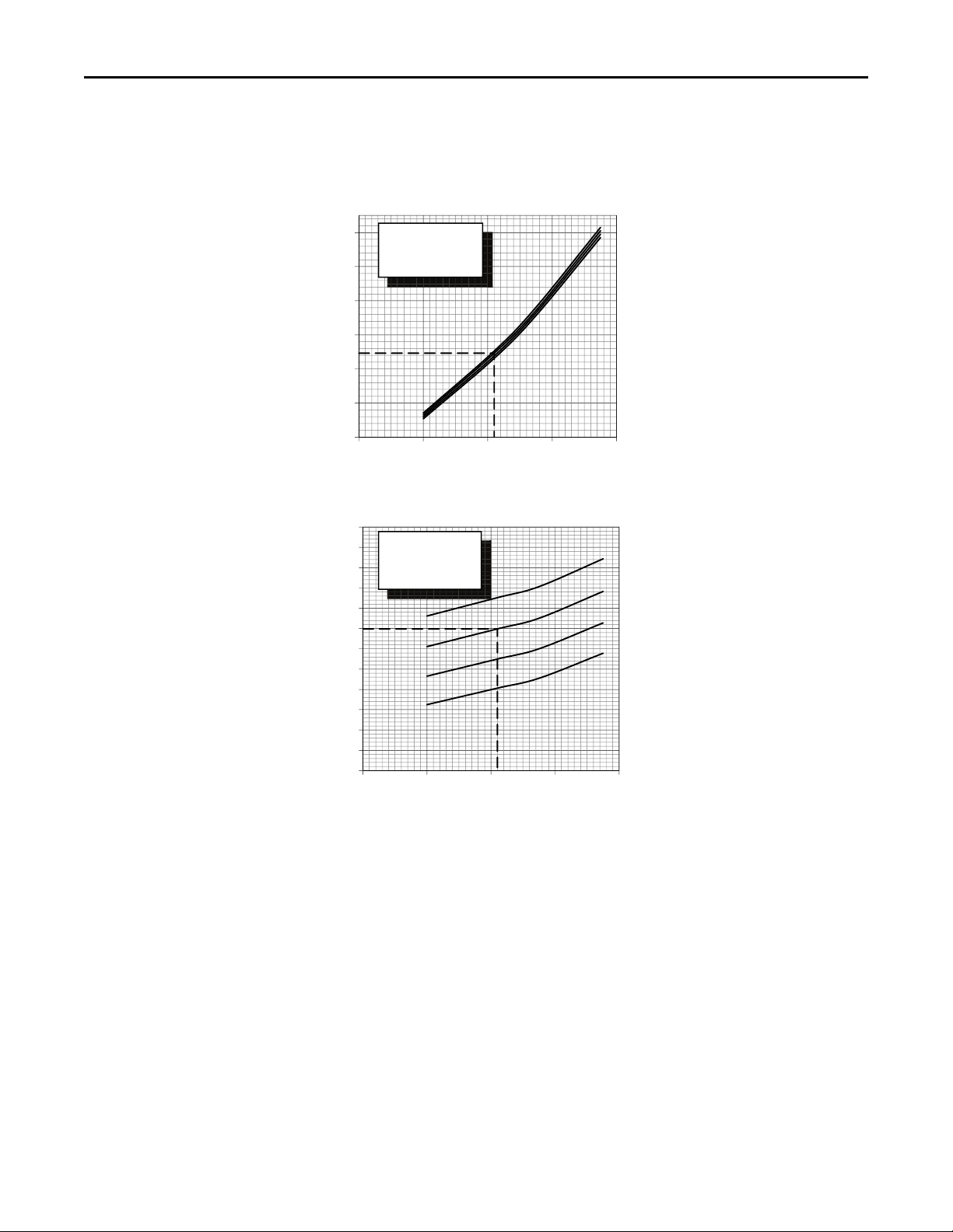
Cooling
Liquid PRESSURE (PSIG)
OUTDOOR TEMPERATURE (Degree F)
SUCTION PRESSURE (PSIG)
OUTDOOR TEMPERATURE (Degree F)
COOLING PERFORMANCE CAN BE CHECKED WHEN THE OUTDOOR TEMP IS ABOVE 65 DEG F.
TO CHECK COOLING PERFORMANCE, SELECT THE PROPER INDOOR CFM, ALLOW PRESSURES TO STABILIZE. MEASURE INDOOR WET BULB
TEMPERATURE, OUTDOOR TEMPERATURE, DISCHARGE AND SUCTION PRESSURES. ON THE PLOTS LOCATE OUTDOOR TEMPERATURE (1);
LOCATE INDOOR WET BULB (2); FIND INTERSECTION OF OD TEMP. & ID W.B. (3); READ LIQUID (4) OR SUCTION (5) PRESSURE IN LEFT COLUMN.
EXAMPLE: (1) OUTDOOR TEMP. 82 F.
(2) INDOOR WET BULB 67 F.
(3) AT INTERSECTION ACTUAL:
(4) DISCHARGE PRESSURE @ 1450 CFM CFM IS 326 PSIG.
DISCHARGE PRESSURE SHOULD BE +/- 10 PSI OF CHART
(5) SUCTION PRESSURE @ 1450 CFM CFM IS 145 PSIG.
SUCTION PRESSURE SHOULD BE +/- 3 PSIG OF CHART
DWG.NO. 4YCC4042E1
110
115
120
125
130
135
140
145
150
155
160
165
170
40 60 80 100 120
200
250
300
350
400
450
500
40 60 80 100 120
(1)
(3)
(3)
(5)
(4)
(2)
(2)
INDOOR ENTERING
WET BULB CURVES
TOP TO BOTTOM
71, 67, 63 AND 59 DEG
INDOOR ENTERING
WET BULB CURVES
TOP TO BOTTOM
71, 67, 63 AND 59
DEG F.
UUnniitt SSttaarrttuupp
Figure 12. Pressure Curve – 4YCC4042E1
32
18-EB40D1-1A-EN
Page 33
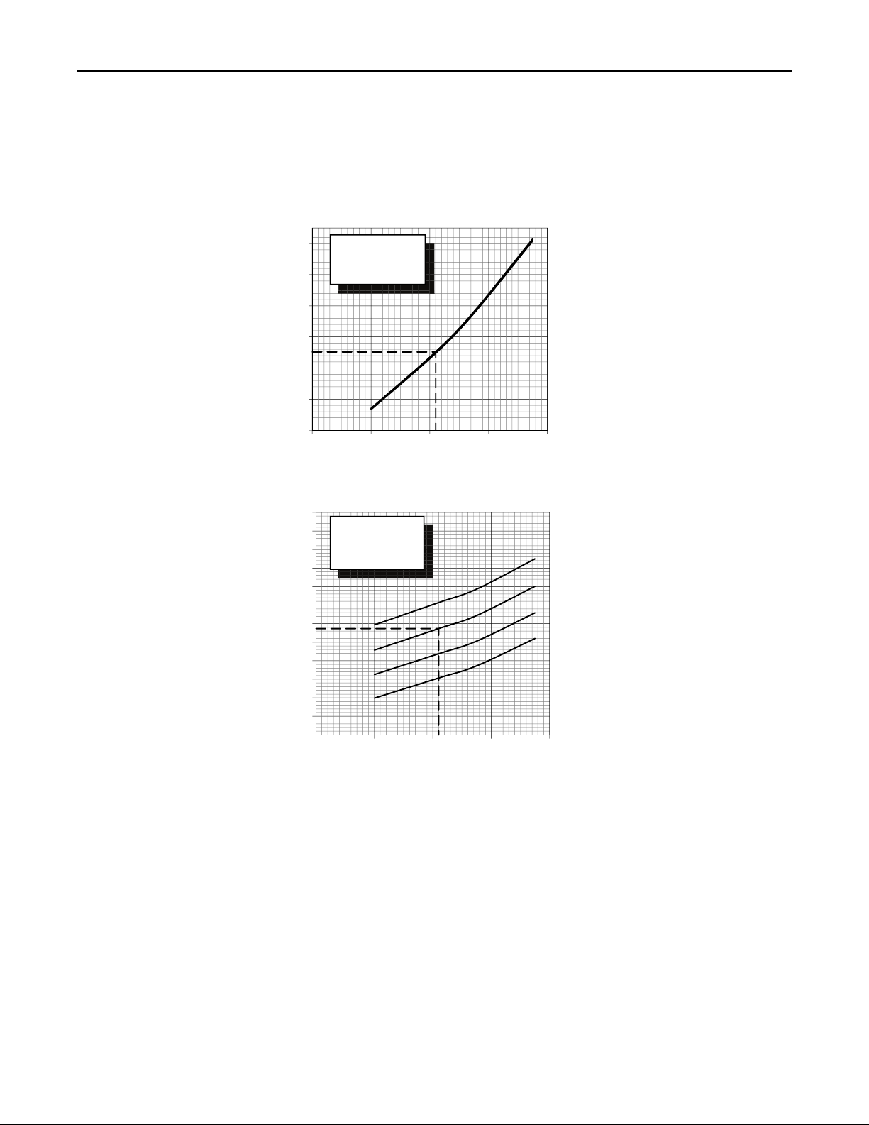
Figure 13. Pressure Curve – 4YCC4048E1
Cooling
Liquid PRESSURE (PSIG)
OUTDOOR TEMPERATURE (Degree F)
SUCTION PRESSURE (PSIG)
OUTDOOR TEMPERATURE (Degree F)
COOLING PERFORMANCE CAN BE CHECKED WHEN THE OUTDOOR TEMP IS ABOVE 65 DEG F.
TO CHECK COOLING PERFORMANCE, SELECT THE PROPER INDOOR CFM, ALLOW PRESSURES TO STABILIZE. MEASURE INDOOR WET BULB
TEMPERATURE, OUTDOOR TEMPERATURE, DISCHARGE AND SUCTION PRESSURES. ON THE PLOTS LOCATE OUTDOOR TEMPERATURE (1);
LOCATE INDOOR WET BULB (2); FIND INTERSECTION OF OD TEMP. & ID W.B. (3); READ LIQUID (4) OR SUCTION (5) PRESSURE IN LEFT COLUMN.
EXAMPLE: (1) OUTDOOR TEMP. 82 F.
(2) INDOOR WET BULB 67 F.
(3) AT INTERSECTION ACTUAL:
(4) DISCHARGE PRESSURE @ 1650 CFM CFM IS 327 PSIG.
DISCHARGE PRESSURE SHOULD BE +/- 10 PSI OF CHART
(5) SUCTION PRESSURE @ 1650 CFM CFM IS 139 PSIG.
SUCTION PRESSURE SHOULD BE +/- 3 PSIG OF CHART
DWG.NO. 4YCC4048E1
110
115
120
125
130
135
140
145
150
155
160
165
170
40 60 80 100 120
200
250
300
350
400
450
500
40 60 80 100 120
(1)
(3)
(3)
(5)
(4)
(2)
(2)
INDOOR ENTERING
WET BULB CURVES
TOP TO BOTTOM
71, 67, 63 AND 59 DEG
INDOOR ENTERING
WET BULB CURVES
TOP TO BOTTOM
71, 67, 63 AND 59
DEG F.
UUnniitt SSttaarrttuupp
18-EB40D1-1A-EN
33
Page 34
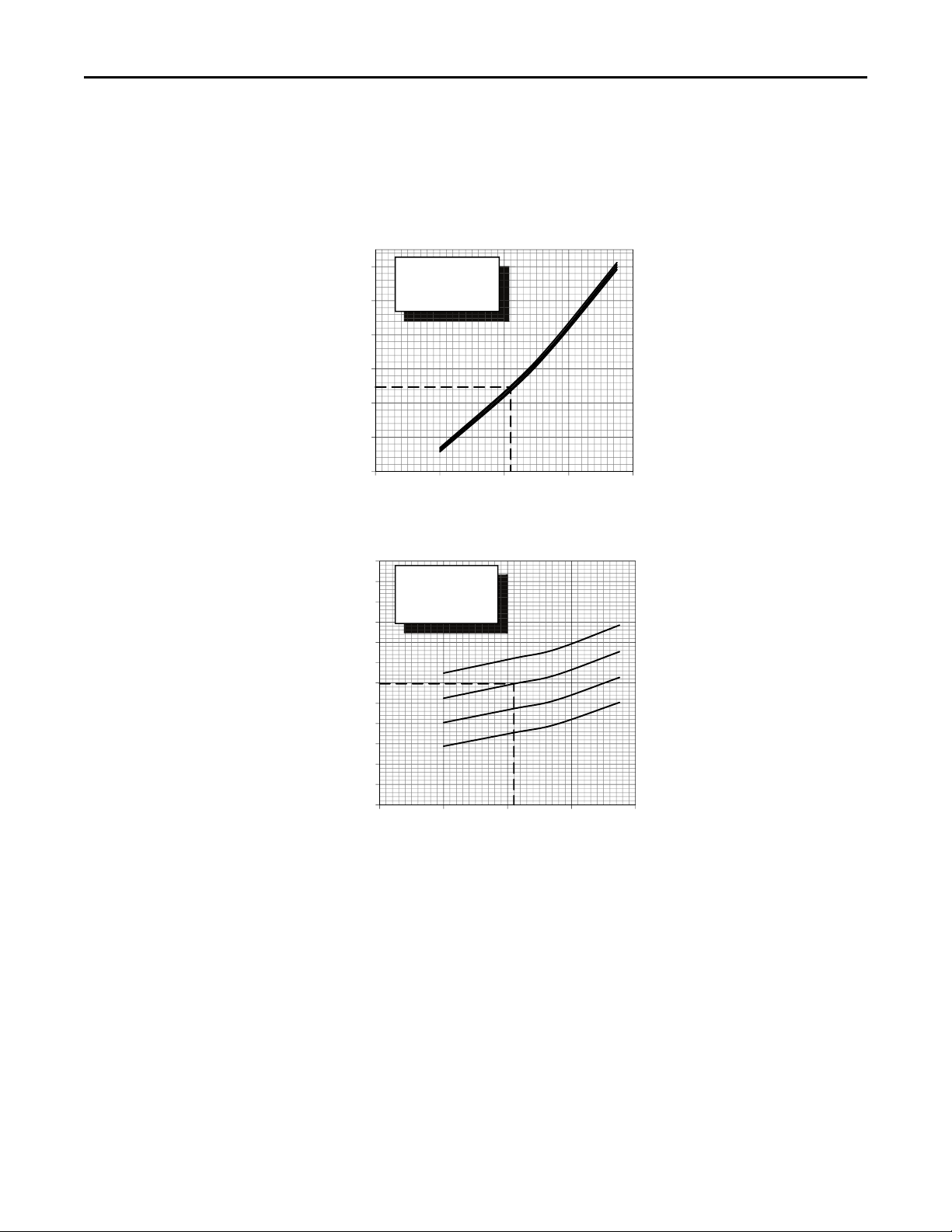
Cooling
Liquid PRESSURE (PSIG)
OUTDOOR TEMPERATURE (Degree F)
SUCTION PRESSURE (PSIG)
OUTDOOR TEMPERATURE (Degree F)
COOLING PERFORMANCE CAN BE CHECKED WHEN THE OUTDOOR TEMP IS ABOVE 65 DEG F.
TO CHECK COOLING PERFORMANCE, SELECT THE PROPER INDOOR CFM, ALLOW PRESSURES TO STABILIZE. MEASURE INDOOR WET BULB
TEMPERATURE, OUTDOOR TEMPERATURE, DISCHARGE AND SUCTION PRESSURES. ON THE PLOTS LOCATE OUTDOOR TEMPERATURE (1);
LOCATE INDOOR WET BULB (2); FIND INTERSECTION OF OD TEMP. & ID W.B. (3); READ LIQUID (4) OR SUCTION (5) PRESSURE IN LEFT COLUMN.
EXAMPLE: (1) OUTDOOR TEMP. 82 F.
(2) INDOOR WET BULB 67 F.
(3) AT INTERSECTION ACTUAL:
(4) DISCHARGE PRESSURE @ 1750 CFM CFM IS 335 PSIG.
DISCHARGE PRESSURE SHOULD BE +/- 10 PSI OF CHART
(5) SUCTION PRESSURE @ 1750 CFM CFM IS 140 PSIG.
SUCTION PRESSURE SHOULD BE +/- 3 PSIG OF CHART
DWG.NO. 4YCC4060E1
110
115
120
125
130
135
140
145
150
155
160
165
170
40 60 80 100 120
200
250
300
350
400
450
500
40 60 80 100 120
(1)
(3)
(3)
(5)
(4)
(2)
(2)
INDOOR ENTERING
WET BULB CURVES
TOP TO BOTTOM
71, 67, 63 AND 59 DEG
INDOOR ENTERING
WET BULB CURVES
TOP TO BOTTOM
71, 67, 63 AND 59
DEG F.
UUnniitt SSttaarrttuupp
Figure 14. Pressure Curve – 4YCC4060E1
34
18-EB40D1-1A-EN
Page 35
Indoor Fan Performance
UUnniitt SSttaarrttuupp
4YCC4024E1060
Motor Speed
Constant
Circulation
Cooling - Low
Cooling - Med
Cooling - High
Heating - Low
Heating - High
Note: Cooling airflow must not exceed 900 CFM due to condensate blowoff.
CFM
WATTS
CFM -
WATTS -
CFM - - -
WATTS - - -
CFM - - - -
WATTS - - - -
CFM
WATTS
CFM - -
WATTS - -
0.0 0.1 0.2 0.3 0.4 0.5 0.6 0.7 0.8 0.9 1
1123
(1123)
143
(143)
900
(891)
114
(115)
1059
(1059)
152
(152)
846
(838)
121
(122)
994
(994)
160
(160)
1122
(1122)
213
(213)
EXTERNAL STATIC PRESSURE (IN.WG)
Horizontal Airflow [Down Airflow]
APPROXIMATELY 40-50% COOLING OR HEATING AIRFLOW
794
(786)
128
(129)
890
(881)
158
(159)
943
(943)
167
(167)
1069
(1069)
221
(221)
729
(722)
138
(138)
836
(828)
167
(167)
908
(899)
248
(249)
889
(889)
175
(175)
1022
(1022)
229
(229)
- - - - - -
- - - - - -
777
(769)
175
(176)
863
(854)
256
(258)
974
(974)
238
(238)
707
(700)
185
(186)
818
(810)
264
(266)
- - - - - -
- - - - - -
922
(922)
245
(245)
- - - -
- - - -
773
(765)
274
(276)
871
(871)
253
(253)
731
(724)
282
(284)
809
(809)
261
(261)
- -
- -
- -
- -
4YCC4030E1070
Motor Speed
Constant
Circulation
Cooling - Low
Cooling - Med
Cooling - High
Heating - Low
Heating - High
Note: Cooling airflow must not exceed 1125 CFM due to condensate blowoff.
CFM
WATTS
CFM
WATTS
CFM - -
WATTS - -
CFM - - - -
WATTS - - - -
CFM
WATTS
CFM - - -
WATTS - - -
0.0 0.1 0.2 0.3 0.4 0.5 0.6 0.7 0.8 0.9 1
1051
(1041)
126
(126)
1148
(1136)
199
(197)
994
(984)
134
(135)
1103
(1091)
208
(205)
939
(930)
142
(143)
1108
(1097)
239
(240)
1061
(1050)
216
(214)
EXTERNAL STATIC PRESSURE (IN.WG)
Horizontal Airflow [Down Airflow]
APPROXIMATELY 40-50% COOLING OR HEATING AIRFLOW
889
(880)
150
(150)
1070
(1059)
247
(248)
1022
(1012)
224
(222)
1158
(1147)
301
(298)
(1017)
(1088)
(1111)
840
(831)
158
(158)
1027
256
(258)
1099
259
(260)
982
(972)
233
(230)
1122
310
(307)
- - - - - -
- - - - - -
975
(965)
267
(269)
1059
(1048)
268
(270)
932
(922)
243
(241)
1084
(1073)
320
(317)
920
(911)
274
(276)
1017
(1007)
278
(279)
1039
(1028)
331
(328)
875
(866)
282
(284)
968
(959)
289
(290)
- - - - -
- - - - -
988
(978)
343
(339)
- - -
- - -
- - -
- - -
- - -
- - -
18-EB40D1-1A-EN
35
Page 36
UUnniitt SSttaarrttuupp
4YCC4036E1070
EXTERNAL STATIC PRESSURE (IN.WG)
Horizontal Airflow [Down Airflow]
Motor Speed
Constant
Circulation
Cooling - Low
Cooling - Med
Cooling - High
Heating - Low
Heating - High
Note: Cooling airflow must not exceed 1350 CFM due to condensate blowoff.
4YCC4036E1090
CFM
WATTS
CFM -
WATTS -
CFM - - - -
WATTS - - - -
CFM - - - - -
WATTS - - - - -
CFM
WATTS
CFM
WATTS
0.0 0.1 0.2 0.3 0.4 0.5 0.6 0.7 0.8 0.9 1
APPROXIMATELY 40-50% COOLING OR HEATING AIRFLOW
1185
(1173)
241
(238)
1386
(1373)
386
(382)
1272
(1259)
352
(354)
1141
(1130)
251
(248)
1354
(1340)
399
(395)
1243
(1231)
361
(363)
1099
(1088)
260
(258)
1311
(1298)
409
(405)
1214
(1202)
372
(374)
1055
(1044)
270
(267)
1276
(1263)
419
(415)
(1174)
(1336)
(1225)
EXTERNAL STATIC PRESSURE (IN.WG)
Horizontal Airflow [Down Airflow]
1186
382
(384)
1349
489
(492)
1009
(999)
279
(277)
1238
430
(425)
1154
(1142)
392
(394)
1319
(1306)
500
(503)
1326
(1299)
516
(519)
968
(958)
289
(286)
1198
(1186)
441
(437)
1116
(1105)
404
(406)
1277
(1264)
511
(514)
1296
(1270)
527
(530)
920
(911)
299
(296)
1164
(1153)
452
(448)
1072
(1061)
416
(418)
1242
(1230)
523
(526)
1263
(1238)
539
(542)
854
(846)
311
(308)
1069
(1058)
432
(428)
- - -
- - -
1199
(1187)
537
(540)
1225
(1201)
552
(555)
808
(800)
320
(316)
805
(797)
320
(317)
1160
(1148)
548
(551)
1183
(1159)
566
(569)
731
(724)
306
(303)
689
(682)
303
(300)
1124
(1113)
558
(561)
1150
(1127)
575
(578)
624
(618)
284
(282)
596
(590)
298
(295)
Motor Speed
Constant
Circulation
Cooling - Low
Cooling - Med
Cooling - High
Heating - Low
Heating - High
Note: Cooling airflow must not exceed 1350 CFM due to condensate blowoff.
CFM
WATTS
CFM
WATTS
CFM -
WATTS -
CFM - - - -
WATTS - - - -
CFM
WATTS
CFM
WATTS
0.0 0.1 0.2 0.3 0.4 0.5 0.6 0.7 0.8 0.9 1
APPROXIMATELY 40-50% COOLING OR HEATING AIRFLOW
1288
(-)
340 (-)
1292
(1285)
343
(343)
1367
(1355)
404
(404)
1254
(1238)
348
(348)
1326
(1320)
410
(410)
1259
(1252)
351
(351)
1341
(1326)
413
(413)
1225
(1207)
357
(357)
1300
(1294)
419
(419)
1230
(1222)
360
(360)
1310
(1295)
421
(421)
1193
(1176)
366
(366)
1271
(1263)
427
(427)
1199
(1186)
369
(369)
1282
(1267)
431
(431)
(1143)
(1234)
(1336)
(1148)
(1235)
1158
375
(375)
1241
437
(437)
1349
489
(492)
1163
378
(378)
1250
439
(439)
1117
(1091)
385
(385)
1201
(1196)
447
(447)
1319
(1306)
500
(503)
1124
(1111)
388
(388)
1212
(1183)
448
(448)
1070
(-)
395 (-)
1107
(1102)
423
(423)
1277
(1264)
511
(514)
1071
(1060)
398
(398)
1075
(1056)
404
(404)
- - - -
- - - -
- - - -
- - - -
1242
(1230)
523
(526)
963
(954)
370
(370)
928
(913)
346
(346)
1199
(1187)
537
(540)
799
(781)
316
(316)
781 (-) 631 (-)
302 (-) 282 (-)
1160
(1148)
548
(551)
638 (-)
293 (-)
1124
(1113)
558
(561)
-
-
-
-
36
18-EB40D1-1A-EN
Page 37
4YCC4042E1060
UUnniitt SSttaarrttuupp
EXTERNAL STATIC PRESSURE (IN.WG)
Horizontal Airflow [Down Airflow]
Motor Speed
Constant
Circulation
Cooling - Low
Cooling - Med
Cooling - High
Heating - Low
Heating - High
Note: Cooling airflow must not exceed 1575 CFM due to condensate blowoff.
4YCC4042E1090
CFM
WATTS
CFM
WATTS
CFM
WATTS
CFM - - - -
WATTS - - - -
CFM
WATTS
CFM -
WATTS -
0.0 0.1 0.2 0.3 0.4 0.5 0.6 0.7 0.8 0.9 1
APPROXIMATELY 40-50% COOLING OR HEATING AIRFLOW
1358
(1345)
224
(228)
1521
(1506)
306
(312)
1104
(1109)
109
(109)
1393
(1379)
233
(238)
1490
(1475)
316
(322)
1042
(1047)
116
(117)
1171
(1177)
154
(155)
1348
(1334)
242
(247)
1448
(1433)
327
(333)
977
(982)
124
(125)
1112
(1117)
162
(163)
1296
(1283)
252
(257)
1391
(1377)
337
(344)
911
(916)
134
(134)
1050
(1055)
172
(173)
(1241)
(1348)
(1514)
EXTERNAL STATIC PRESSURE (IN.WG)
Horizontal Airflow [Down Airflow]
1253
262
(267)
1362
348
(354)
1529
455
(464)
841
(845)
142
(143)
990
(995)
182
(182)
- - - - - -
- - - - - -
1338
(1325)
359
(366)
1491
(1476)
467
(477)
764
(767)
152
(153)
927
(931)
192
(193)
1315
(1302)
369
(377)
1467
(1453)
477
(487)
687
(690)
161
(162)
821
(856)
203
(204)
1307
(1293)
382
(389)
1425
(1411)
490
(499)
598
(601)
171
(172)
779
(783)
214
(215)
1254
(1241)
395
(403)
1385
(1371)
503
(513)
- - -
- - -
704
(707)
225
(226)
- -
- -
1345
(1331)
513
(523)
- -
- -
-
-
Motor Speed
Constant
Circulation
Cooling - Low
Cooling - Med
Cooling - High
Heating - Low
Heating - High
Note: Cooling airflow must not exceed 1575 CFM due to condensate blowoff.
CFM
WATTS
CFM
WATTS
CFM
WATTS
CFM - - - -
WATTS - - - -
CFM
WATTS
CFM
WATTS
0.0 0.1 0.2 0.3 0.4 0.5 0.6 0.7 0.8 0.9 1
APPROXIMATELY 40-50% COOLING OR HEATING AIRFLOW
1358
(1345)
224
(228)
1521
(1506)
306
(312)
1419
(1426)
240
(241)
1559
(1567)
313
(315)
1393
(1379)
233
(238)
1490
(1475)
316
(322)
1380
(1387)
250
(251)
1524
(1531)
324
(325)
1348
(1334)
242
(247)
1448
(1433)
327
(333)
1341
(1348)
259
(260)
1483
(1491)
335
(337)
1296
(1283)
252
(257)
1391
(1377)
337
(344)
1295
(1301)
269
(270)
1443
(1450)
346
(347)
(1241)
(1348)
(1514)
(1255)
(1408)
1253
262
(267)
1362
348
(354)
1529
455
(464)
1249
279
(281)
1401
356
(358)
- - - - - -
- - - - - -
1338
(1325)
359
(366)
1491
(1476)
467
(477)
1204
(1210)
291
(292)
1363
(1370)
367
(368)
1315
(1302)
369
(377)
1467
(1453)
477
(487)
1160
(1166)
302
(303)
1319
(1326)
379
(381)
1307
(1293)
382
(389)
1425
(1411)
490
(499)
1115
(1120)
312
(314)
1276
(1282)
392
(394)
1254
(1241)
395
(403)
1385
(1371)
503
(513)
1069
(1074)
323
(325)
1233
(1239)
403
(405)
- -
- -
1345
(1331)
513
(523)
1015
(1020)
333
(335)
1195
(1201)
415
(417)
-
-
961
(966)
348
(349)
1147
(1152)
428
(430)
18-EB40D1-1A-EN
37
Page 38
UUnniitt SSttaarrttuupp
4YCC4048E1070
Motor Speed
Constant
Circulation
Cooling - Low
Cooling - Med
Cooling - Med High
Cooling - High
Heating - Low
Heating - High
Note: Cooling airflow must not exceed 1800 CFM due to condensate blowoff.
CFM
WATTS
CFM
WATTS
CFM
WATTS
CFM -
WATTS -
CFM - - - - -
WATTS - - - - -
CFM
WATTS
CFM -
WATTS -
0.0 0.1 0.2 0.3 0.4 0.5 0.6 0.7 0.8 0.9 1
1583
(1567)
302
(308)
1763
(1745)
414
(422)
1120
(1126)
117
(117)
1542
(1526)
313
(320)
1723
(1706)
426
(434)
1786
(1768)
577
(589)
1047
(1052)
126
(127)
1204
(1210)
176
(177)
1502
(1487)
324
(330)
1689
(1672)
436
(444)
1757
(1739)
591
(603)
980
(985)
135
(136)
1149
(1154)
185
(186)
EXTERNAL STATIC PRESSURE (IN.WG)
Horizontal Airflow [Down Airflow]
APPROXIMATELY 40-50% COOLING OR HEATING AIRFLOW
1460
(1445)
332
(339)
1648
(1632)
448
(457)
1729
(1712)
604
(616)
914
(918)
145
(146)
1095
(1100)
195
(196)
(1401)
(1593)
(1683)
(1048)
1415
346
(352)
1609
459
(468)
1700
617
(629)
840
(845)
156
(156)
1043
205
(206)
- - - - - -
- - - - - -
1568
(1552)
471
(480)
1675
(1658)
631
(644)
1769
(1751)
613
(625)
758
(762)
168
(168)
989
(994)
216
(217)
1527
(1512)
483
(493)
1648
(1632)
643
(656)
1728
(1711)
631
(644)
674
(677)
179
(180)
926
(930)
227
(228)
1488
(1473)
495
(505)
1624
(1608)
655
(668)
1688
(1671)
643
(656)
581
(584)
188
(189)
858
(862)
239
(240)
1447
(1433)
510
(520)
1504
(1489)
599
(611)
1652
(1635)
647
(660)
- - -
- - -
798
(802)
249
(250)
- -
- -
- -
- -
1545
(1530)
611
(623)
- -
- -
-
-
4YCC4048E1090
Motor Speed
Constant
Circulation
Cooling - Low
Cooling - Med
Cooling - Med High
Cooling - High
Heating - Low
Heating - High
Note: Cooling airflow must not exceed 1800 CFM due to condensate blowoff.
CFM
WATTS
CFM
WATTS
CFM
WATTS
CFM -
WATTS -
CFM - - - - -
WATTS - - - - -
CFM
WATTS
CFM
WATTS
0.0 0.1 0.2 0.3 0.4 0.5 0.6 0.7 0.8 0.9 1
1583
(1567)
302
(308)
1763
(1745)
414
(422)
1419
(1426)
240
(241)
1559
(1567)
313
(315)
1542
(1526)
313
(320)
1723
(1706)
426
(434)
1786
(1768)
577
(589)
1380
(1387)
250
(251)
1524
(1531)
324
(325)
1502
(1487)
324
(330)
1689
(1672)
436
(444)
1757
(1739)
591
(603)
1341
(1348)
259
(260)
1483
(1491)
335
(337)
EXTERNAL STATIC PRESSURE (IN.WG)
Horizontal Airflow [Down Airflow]
APPROXIMATELY 40-50% COOLING OR HEATING AIRFLOW
1460
(1445)
332
(339)
1648
(1632)
448
(457)
1729
(1712)
604
(616)
1295
(1301)
269
(270)
1443
(1450)
346
(347)
(1401)
(1593)
(1683)
(1255)
(1408)
1415
346
(352)
1609
459
(468)
1700
617
(629)
1249
279
(281)
1401
356
(358)
- - - - - -
- - - - - -
1568
(1552)
471
(480)
1675
(1658)
631
(644)
1769
(1751)
613
(625)
1204
(1210)
291
(292)
1363
(1370)
367
(368)
1527
(1512)
483
(493)
1648
(1632)
643
(656)
1728
(1711)
631
(644)
1160
(1166)
302
(303)
1319
(1326)
379
(381)
1488
(1473)
495
(505)
1624
(1608)
655
(668)
1688
(1671)
643
(656)
1115
(1120)
312
(314)
1276
(1282)
392
(394)
1447
(1433)
510
(520)
1504
(1489)
599
(611)
1652
(1635)
647
(660)
1069
(1074)
323
(325)
1233
(1239)
403
(405)
- -
- -
- -
- -
1545
(1530)
611
(623)
1015
(1020)
333
(335)
1195
(1201)
415
(417)
-
-
961
(966)
348
(349)
1147
(1152)
428
(430)
38
18-EB40D1-1A-EN
Page 39
4YCC4060E1090
UUnniitt SSttaarrttuupp
EXTERNAL STATIC PRESSURE (IN.WG)
Horizontal Airflow [Down Airflow]
Motor Speed
Constant
Circulation
Cooling - Low
Cooling - Med
Cooling - High
Heating - Low
Heating - High
Note: Cooling airflow must not exceed 2250 CFM due to condensate blowoff.
4YCC4060E1115
CFM
WATTS
CFM
WATTS
CFM
WATTS
CFM
WATTS
CFM
WATTS
CFM -
WATTS -
0.0 0.1 0.2 0.3 0.4 0.5 0.6 0.7 0.8 0.9 1
APPROXIMATELY 40-50% COOLING OR HEATING AIRFLOW
1857
(1831)
515
(524)
2031
(2003)
594
(611)
2083
(2054)
749
(770)
1534
(1541)
281
(282)
1831
(1802)
523
(533)
2003
(1975)
609
(627)
2058
(2030)
759
(781)
1489
(1497)
292
(293)
1594
(1602)
348
(350)
1800
(1765)
533
(545)
1974
(1946)
624
(642)
2032
(2010)
769
(790)
1445
(1452)
304
(305)
1551
(1558)
361
(363)
1766
(1728)
544
(558)
1940
(1913)
639
(658)
2003
(1976)
779
(804)
1403
(1410)
314
(316)
1511
(1518)
373
(374)
(1880)
(1946)
(1367)
(1478)
EXTERNAL STATIC PRESSURE (IN.WG)
Horizontal Airflow [Down Airflow]
- - - - - - -
- - - - - - -
1907
653
(672)
1974
788
(819)
1361
325
(327)
1471
384
(386)
1874
(1848)
667
(686)
1943
(1911)
803
(832)
1314
(1321)
337
(339)
1430
(1437)
396
(398)
1837
(1811)
681
(701)
1911
(1879)
816
(845)
1275
(1281)
348
(349)
1386
(1392)
409
(411)
1805
(1780)
695
(715)
1877
(1848)
830
(858)
1234
(1240)
358
(360)
1344
(1351)
420
(423)
1771
(1746)
709
(730)
1843
(1817)
845
(872)
- - -
- - -
1305
(1311)
432
(434)
- -
- -
1807
(1781)
860
(887)
1265
(1271)
443
(445)
-
-
-
-
Motor Speed
Constant
Circulation
Cooling - Low
Cooling - Med
Cooling - High
Heating - Low
Heating - High
Note: Cooling airflow must not exceed 2250 CFM due to condensate blowoff.
CFM
WATTS
CFM
WATTS
CFM
WATTS
CFM
WATTS
CFM
WATTS
CFM -
WATTS -
0.0 0.1 0.2 0.3 0.4 0.5 0.6 0.7 0.8 0.9 1
APPROXIMATELY 40-50% COOLING OR HEATING AIRFLOW
1857
(1831)
515
(524)
2031
(2003)
594
(611)
2083
(2054)
749
(770)
1827
(1815)
492
(510)
1831
(1802)
523
(533)
2003
(1975)
609
(627)
2058
(2030)
759
(781)
1792
(1790)
505
(520)
1927
(1910)
614
(630)
1800
(1765)
533
(545)
1974
(1946)
624
(642)
2032
(2010)
769
(790)
1757
(1757)
517
(532)
1894
(1875)
627
(634)
1766
(1728)
544
(558)
1940
(1913)
639
(658)
2003
(1976)
779
(804)
1721
(1712)
529
(549)
1861
(1839)
639
(647)
(1880)
(1946)
(1679)
(1803)
- - - - - - -
- - - - - - -
1907
653
(672)
1974
788
(819)
1685
541
(560)
1824
651
(660)
1874
(1848)
667
(686)
1943
(1911)
803
(832)
1646
(1648)
553
(570)
1788
(1773)
664
(672)
1837
(1811)
681
(701)
1911
(1879)
816
(845)
1605
(1613)
566
(582)
1750
(1736)
677
(685)
1805
(1780)
695
(715)
1877
(1848)
830
(858)
1570
(1574)
577
(596)
1711
(1704)
689
(698)
1771
(1746)
709
(730)
1843
(1817)
845
(872)
- - -
- - -
1674
(1661)
702
(712)
- -
- -
1807
(1781)
860
(887)
1639
(1622)
715
(726)
-
-
-
-
18-EB40D1-1A-EN
39
Page 40
UUnniitt SSttaarrttuupp
To set indoor motor for the desired speed options,
connect the motor leads in the taps as shown below:
Table 20. Motor Wiring: 4YCC4024 - 42, 4YCC4060
MOTOR WIRING MOTOR TAP
MODE/SPEED
CONSTANT CIRCULATION
COOLING-LOW & HEATING-LOW
COOLING-LOW & HEATING-HIGH
COOLING-MED & HEATING-LOW
COOLING-MED & HEATING-HIGH
COOLING-HIGH & HEATING-LOW
COOLING-HIGH & HEATING-HIGH
G signal (GR - green wire), Y signal (YL - yellow wire), W signal (PR - purple wire)
Table 21. Motor Wiring: 4YCC4048
MOTOR WIRING MOTOR TAP
MODE/SPEED
CONSTANT CIRCULATION
COOLING-LOW & HEATING-LOW
COOLING-LOW & HEATING-HIGH
COOLING-MED LOW& HEATING-LOW
COOLING-MED LOW & HEATING-HIGH
COOLING-MED HIGH & HEATING-LOW
COOLING-MED HIGH & HEATING-HIGH
COOLING-HIGH & HEATING-LOW
COOLING-HIGH & HEATING-HIGH
G signal (GR - green wire), Y signal (YL - yellow wire), W signal (PR - purple wire)
1 2 3 4 5
G (GR)
G (GR) Y (YL) W (PR)
G (GR) Y (YL) W (PR)
G (GR) Y (YL) W (PR)
G (GR) Y (YL) W (PR)
G (GR) W (PR) Y (YL)
G (GR) Y (YL) W (PR)
1 2 3 4 5
G (GR)
G (GR) Y (YL) W (PR)
G (GR) Y (YL) W (PR)
G (GR) Y (YL) W (PR)
G (GR) Y (YL) W (PR)
G (GR) W (PR) Y (YL)
G (GR) W (PR) Y (YL)
G (GR) W (PR) Y (YL)
G (GR) W (PR) Y (YL)
40
18-EB40D1-1A-EN
Page 41
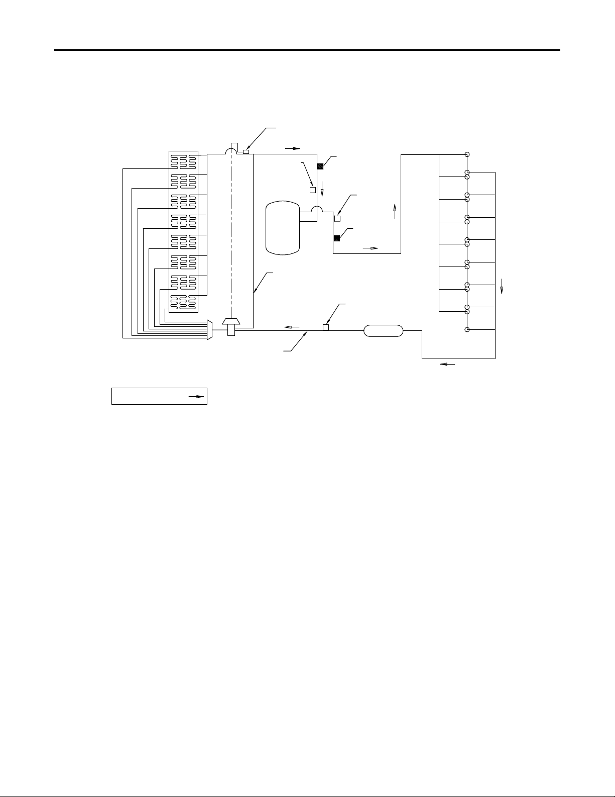
Refrigerant Circuit
INDOOR
COIL
EXPANSION
VALVE BU
LB
OUTDOOR
COIL
LPCO
SCHRADER
VALVE LO
EQUALIZER
LINE
SCHRADER VALVE
LIQUID
LIQUID
LINE
DRIER
INDICATES DIRECTION OF
REFRIGERATION FLOW
COMPRESSOR
HPCO
EXPANSION
VALVE
SCHRADER
VALVE HI
UUnniitt SSttaarrttuupp
18-EB40D1-1A-EN
41
Page 42
UUnniitt SSttaarrttuupp
Troubleshooting Chart
PP--PPRRIIMMAARRYY CCAAUUSSEESS // SS--SSEECCOONNDDAARRYY CCAAUUSSEESS
SYSTEM FAULTS
Power Supply
Compr. I0L
Run Capacitor
High Voltage Wiring
REFRIGERANT CIRCUIT
Liquid Pressure too High
Liquid Pressure too Low
Suction Pressure too High
Suction Pressure too Low S S P S
Liquid Refrigerant
Floodback (TXV System)
I.D. Coil Frosting
Compressor Runs
Inadequate or No Cooling
ELECTRICAL
Compressor & O.D. Fan Do
Not Start
Compressor will not Start
but O.D. Fan Runs
O.D. Fan will Not Start P P
Compressor Hums but will
Not Start
Compressor Cycles on IOL
I.D. Blower willnot Start P S S P P
P P S S P P P
P S P P P S
P P P P S S
P S P P P S P S P S S S S S S S
Start Relay
Start capacitor
Contactor Contacts
Low Voltage Wiring
Contactor Coil
Control Transformer
Low Voltage Fuse
Low Superheat
Stuck Compressor
Ineffecient Compressor
S P S S S
S P P S S
S P P S S S S P S
Refrigerant Overcharge
Refrigerant Undercharge
P S P S S
P S P S
Noncondensables
Excessive Evap. Load
Restricted O.D. Airflow
TXV Stuck Open
O.D. Air Recirculation
S S P
High Superheat
Restricted I.D. Airflow
Ref. Circuit Restrictions
42
18-EB40D1-1A-EN
Page 43

NNootteess
18-EB40D1-1A-EN
43
Page 44
Important Product Information
Packaged Unit Serial Number_____________________________________________________
Packaged Unit Model Number_____________________________________________________
Date of Installation_______________________________________________________________
Dealer___________________________________________________________________________
Service Information
Call your installing dealer if the unit is inoperative. Before you call, always check the following to be sure service is required:
1. Be sure the main switch that supplies power to the unit is in the ON position.
2. Replace any burned-out fuses or reset circuit breakers.
3. Be sure the thermostat is properly set.
Service Phone ___________________________________________________________________
About Trane and American Standard Heating and Air Conditioning
Trane and American Standard create comfortable, energy efficient indoor environments for residential applications. For
more information, please visit www.trane.com or www.americanstandardair.com.
The AHRI Certified mark indicates company participation in the AHRI Certification program. For verification of individual certified products, go to ahridirectory.org.
The manufacturer has a policy of continuous data improvement and it reserves the right to change design and specifications without notice. We are committed to
using environmentally conscious print practices.
18-EB40D1-1A-EN 29 Mar 2022
Supersedes (New)
©2022
 Loading...