

Page 1
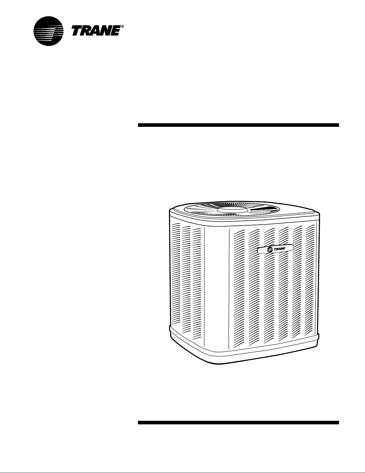
Split System
Heat Pump Product
& Performance Data
XB 13
2TWB3018-060
1½ – 5 Tons
PUB. NO. 22-1771-04
Page 2
Features and
Benefits
• Climatuff® compressor
• All aluminum Spine Fin™ coil
• DuraTuff™ base, fast complete drain,
weather proof
• Polyslate gray cabinet high gloss with
fan motor cover
• Quick-Sess™ cabinet, easy service
access and refrigerant connections
with full coil protection
• Corrosion resistant finish and fasteners
• Internal high/low pressure and
temperature protection
• Liquid line filter-drier
• Easy single side service
• Compressor sump heat all models
• Demand Defrost Control
• Easy top & fan removal
• R-22 refrigerant
• 100% line run test
• Low ambient cooling to 55°F as
shipped
• Low ambient cooling to 40°F with
EDC accessory AY28X084
• Low ambient cooling to 30°F with
EDC accessory AY28X084 and TXV
• Extended warranties available
(Not Factory Supplied)
© 2011 Trane 2 22-1771-04
Page 3
Contents
Features and Benefits 2
General Data 4
Product Specifications 4
A-weighted Sound Power Level [dB(A)] 4
Accessory Description and Usage 5
AHRI Standard Capacity Rating Conditions 5
Model Nomenclature 6
Electrical Data 7
Dimensions 9
Mechanical Specification Options 10
22-1771-04 3
Page 4

General
Data
Product Specifications
Model No.
Electrical Data V/Ph/Hz
1
2
2TWB3018A1 2TWB3024A1 2TWB3030A1 2TWB3036A1
200/230/1/60 200/230/1/60 200/230/1/60 200/230/1/60
Min Cir Ampacity 8 12 13 19
Max Fuse Size (Amps) 15 20 20 30
Compressor CLIMATUFF
®
CLIMATUFF
®
CLIMATUFF
®
CLIMATUFF
®
RL Amps - LR Amps 5.9 - 38.6 8.7 - 57.8 9.5 - 63 14.1 - 90.8
Outdoor Fan FL Amps 0.6 1.3 0.9 1.4
Fan HP 1/15 1/4 1/8 1/6
Fan Dia (inches) 19.0 19.0 23.0 27.6
Coil Spine Fin™ Spine Fin™ Spine Fin™ Spine Fin™
Refrigerant R-22
Line Size - (in.) O.D. Gas
Line Size - (in.) O.D. Liquid
(Not Factory Supplied)
3
3
5/10-LB/OZ 5/11-LB/OZ 6/07-LB/OZ 7/06-LB/OZ
5/8 3/4 3/4 7/8
1/4 5/16 5/16 3/8
Dimensions H x W x D (Crated) 37.2 x 26.7 x 30 37.2 x 26.7 x 30 42 x 30.1 x 33 42.4 x 35.1 x 38.7
Weight - Shipping 202 205 240 291
Weight - Net 182 184 212 256
Start Components YES YES YES YES
Sound Enclosure N O NO NO YES
Compressor Sump Heat YES YES YES YES
Optional Accessories:
4
Anti-short Cycle Timer TAYASCT501A TAYASCT501A TAYASCT501A TAYASCT501A
Evaporator Defrost Control A/C AY28X084 AY28X084 AY28X084 AY28X084
Rubber Isolator Kit BAYISLT101 BAYISLT101 BAYISLT101 BAYISLT101
Snow Leg-Base & Cap 4" High BAYLEGS002 BAYLEGS002 BAYLEGS002 BAYLEGS002
Snow Leg-4" Extension BAYLEGS003 BAYLEGS003 BAYLEGS003 BAYLEGS003
Extreme Condition Mounting KitBAYECMT023 BAYECMT023 BAYECMT023 BAYECMT004
Refrigerant Lineset
1
Certified in accordance with the Air-Source Unitary Heat Pump equipment certification program which is based on AHRI Standard 210/240.
2
Calculated in accordance with N.E.C. Use only HACR circuit breakers or fuses.
3
Standard line lengths - 60', Standard lift - 60' Suction and Liquid line.
For Greater lengths and lifts refer to refrigerant piping software Pub# 32-3312-0†. (†denotes latest revision)
4
For accessory description and usage, see page 5.
5
* = 15, 20, 25, 30, 40 and 50 foot lineset available.
5
TAYREFLN1* TAYREFLN2* TAYREFLN2* TAYREFLN3*
A-weighted Sound Power Level [dB(A)]
SOUND POWER A-WEIGHTED FULL OCTAVE SOUND POWER LEVEL dB - [dB(A)]
MODEL LEVEL [dB(A)] 63 125 250 500 1000 2000 4000 8000
2TWB3018A1 74 43.5 52.1 57.0 65.5 67.3 66.8 62.1 55.4
2TWB3024A1 79 51.3 56.1 61.7 71.5 73.1 71.8 64.3 55.8
2TWB3030A1 79 43.8 58.8 62.2 69.2 72.1 71.4 62.5 56.8
2TWB3036A1 79 47.1 60.4 67.8 73.5 73.7 71.6 63.8 51.4
2TWB3042A1 80 48.6 59.9 66.9 73.0 75.2 70.3 64.4 55.2
2TWB3048A1 78 45.4 58.8 66.1 72.5 72.5 69.8 63.0 52.5
2TWB3060A1 79 46.7 55.2 66.5 73.5 73.8 71.8 65.8 56.7
Note: Tested in accordance with AHRI Standard 270.95. (Not listed with AHRI)
4 22-1771-04
Page 5

General
Data
Product Specifications
Model No.
Electrical Data V/Ph/Hz
Min Cir Ampacity 21 25 32
Max Fuse Size (Amps) 35 40 50
Compressor CLIMATUFF
RL Amps - LR Amps 15.4 - 93.5 18.6 - 93.4 25.0 - 148
Outdoor Fan FL Amps 1.4 1.4 1.2
Fan HP 1/6 1/5 1/5
Fan Dia (inches) 27.6 27.6 27.6
Coil Spine Fin™ Spine Fin™ Spine Fin™
Refrigerant R-22
Line Size - (in.) O.D. Gas
Line Size - (in.) O.D. Liquid
Dimensions H x W x D (Crated) 46.4 x 35.1 x 38.7 46.4 x 35.1 x 38.7 46.4 x 35.1 x 38.7
Weight - Shipping 308 312 291
Weight - Net 272 276 255
Start Components YES YES NO
Sound Enclosure YES YES NO
Compressor Sump Heat YES YES YES
Optional Accessories:
Anti-short Cycle Timer TAYASCT501A TAYASCT501A TAYASCT501A
Evaporator Defrost Control A/C AY28X084 AY28X084 AY28X084
Rubber Isolator Kit BAYISLT101 BAYISLT101 BAYISLT101
Snow Leg-Base & Cap 4" High BAYLEGS002 BAYLEGS002 BAYLEGS002
Snow Leg-4" Extension BAYLEGS003 BAYLEGS003 BAYLEGS003
Extreme Condition Mounting Kit BAYECMT004 BAYECMT004 BAYECMT004
Refrigerant Lineset
1
2
(Not Factory Supplied)
3
3
4
5
2TWB3042A1 2TWB3048A1 2TWB3060A1
200/230/1/60 200/230/1/60 208/230/1/60
®
9/09-LB/OZ 9/09-LB/OZ 9/08-LB/OZ
7/8 1-1/8 1-1/8
3/8 3/8 3/8
TAYREFLN3* TAYREFLN4* TAYREFLN4*
CLIMATUFF
®
CLIMATUFF® - SCROLL
Accessory Description and Usage
Anti-Short Cycle Timer — Solid state timing device that
prevents compressor recycling until 5 minutes have elapsed
after satisfying call or power interruptions. Use in area with
questionable power delivery, commercial applications, long
lineset, etc.
Evaporator Defrost Control — SPST Temperature actuated switch that cycles the condenser off as indoor coil
reaches freeze-up conditions. Used for low ambient cooling
to 30°F with TXV.
Rubber Isolators — 5 large rubber donuts to isolate
condensing unit from transmitting energy into mounting
frame or pad. Use on any application where sound transmission needs to be minimized.
Hard Start kit — Start capacitor and relay to assist compressor
motor startup. Use in areas with marginal power supply, on
long linesets, low ambient conditions, etc.
Extreme Condition Mount Kit — Bracket kits to securely
mount condensing unit to a frame or pad without removing any
panels. Use in areas with high winds, or on commercial roof
tops, etc.
22-1771-04 5
AHRI Standard Capacity Rating Conditions
AHRI STANDARD 210/240 RATING CONDITIONS —
(A) Cooling 80°F DB, 67°F WB air entering indoor coil,
95°F DB air entering outdoor coil.
(B) High Temperature Heating 47°F DB, 43°F WB air entering
outdoor coil, 70°F DB air entering indoor coil.
(C) Low Temperature Heating 17°F DB, 15°F WB air entering
outdoor coil, 70°F DB air entering indoor coil.
(D) Rated indoor airflow for heating is the same as for cooling.
AHRI STANDARD 270 RATING CONDITIONS — (Noise
rating numbers are determined with the unit in cooling
operation.) Standard Noise Rating number is at 95°F outdoor
air.
SPLIT SYSTEM
Page 6

Model
Nomenclature
Outdoor Units
Refrigerant Type
2 = R-22
4 = R-410A
TRANE
Product Type
W = Split Heat Pump
T = Split Cooling
Product Family
Z = Leadership – Two Stage
X = Leadership
R = Replacement/Retail
B = Basic
A = Light Commercial
Family SEER
0 = 10 3 = 13 6 = 16
1 = 11 4 = 14 8 = 18
2 = 12 5 = 15 9 = 19
Split System Connections 1-6 Tons
0 = Brazed
Nominal Capacity in 000s of BTUs
Major Design Modifications
Power Supply
1 = 200-230/1/60 or 208-230/1/60
3 = 200-230/3/60
4 = 460/3/60
Secondary Function
Minor Design Modifications
Unit Parts Identifier
2TWB3036A1000AA
High Efficiency
TUD 1 B 0 8 0 A 9 H 3 1 A A
Furnaces
Furnace Configuration
TU = Upflow / Horizontal
TD = Downflow / Horizontal
Type
D = 80% Premium
X = 90% Premium
Number of Heating Stages
1 = Single Stage
2 = Two Stage
3 = Three Stage
Cabinet Width
A = 14.5" Cabinet Width
B = 17.5" Cabinet Width
C = 21.0" Cabinet Width
D = 24.5" Cabinet Width
Heating Input
080 = 80,000 BTUH
Major Design Change
Power Supply / Fuel
9 = 115 Volts / Natural Gas
F = 115 Volts / Natural Gas with Integrated ifD Filter
Airflow Capacity for Cooling
36 = 3 Ton Standard PSC Motor
H3 = 3 Ton High Efficiency Motor
V3 = 3 Ton Variable Speed Motor
Draft Inducer Speeds
1 = Single Speed
2 = Two Speed
V = Variable Speed
Minor Design Change
Service Digit – Not Orderable
Air Handlers –
4TEE3F3 6 A 1 A A000
Residential
Refrigerant Type
4 = R-410A
2 = R-22
Application
TE = Fully Convertible
TG = Semi Convertible
TF = Front Return
TV = Ver tical
Product Family
E = Leadership – Variable Speed
P = Leadership
C = Replacement/Retail
B = Basic
Flow Control
3 = Nonbleed TXV
4 = FCCV*
Feature Identifier
0 = Standard Unit
F = Air-Tite™
Nominal Capacity in 000s of BTUs
Major Design Modifications
Power Supply
1 = Single Phase
Electrical Connection
0 = Pig Tails
B = Circuit Breaker
D = Pull Disconnect
Future Option – Factory Installed Heater Nominal KW Value
Minor Design Modifications
Unit Parts Identifier
NOTE: There will be a phase-in of new model numbers for new
air handlers over next 2 years.
*Shipped with R-22 FCCV
Heat Pump /
2TXCB0 3 6 AC 3HCA A
Cooling Coils
Refrigerant Type
2 = R-22 4 = R-410A
Product Family
T = Premium (Heat Pump or Convertible Coil)
C = Standard (Cooling Only)
Coil Design
X = Direct Expansion Evaporator Coil
Product Family
C = Cased A Coil
A = Uncased A Coil
F = Cased Horizontal Flat Coil
Coil Width (Cased / Uncased)
A = 14.5" / 13.3" C = 21.0" / 19.8" H = 10.5"
B = 17.5" / 16.3" D = 24.5" / 23.3"
Refrigerant Line Coupling
0 = Brazed
Nominal Capacity in 000s of BTUs
Major Design Change
Efficiency
C = Standard S = Hi Efficiency
Refrigerant Control
3 = TXV – Non-Bleed
Coil Circuitry
H = Heat Pump
C = Cooling Only
Airflow Configuration
A = Upflow Only
U = Upflow / Downflow
H = Horizontal Only
C = Convertible – Upflow, Downflow, Left Airflow
M = Conver tible – Upflow, Downflow, Left or Right Airflow
Minor Design Change
Unit Parts Identifier
6 22-1771-04
Page 7

Electrical
Data
Schematic Diagrams
(SEE LEGEND)
2TWB3018,024,030,036,042A 2TWB3048A
Printed from D155595P01
22-1771-04 7
Printed from D155596P01
Page 8

Electrical
Data
Schematic Diagrams
2TWB3060A LEGEND
SYMBOLS
8 22-1771-04
Page 9

Dimensions
2TWB3 Outline Drawing
NOTE: ALL DIMENSIONS ARE IN MM (INCHES)
MODELS BASE FIG. A B C D E F G H J K
2TWB3018A 2 2 832 (32-3/4) 724 (28-1/2) 651 (25-5/8) 5/8 1/4 127 (5) 57 (2-1/4) 181 (7-1/8) 44 (1-3/4) 457 (18)
2TWB3024A 2 1 832 (32-3/4) 724 (28-1/2) 651 (25-5/8) 3/4 5/16 137 (5-3/8) 65 (2-5/8) 210 (8-1/4) 57 (2-1/4) 457 (18)
2TWB3030A 3 1 933 (36-3/4) 829 (32-5/8) 756 (29-3/4) 3/4 5/16 143 (5-5/8) 92 (3-5/8) 210 (8-1/4) 79 (3-1/8) 508 (20)
2TWB3036A 4 1 943 (37-1/8) 946 (37-1/4) 870 (34-1/4) 7/8 3/8 152 (6) 98 (3-7/8) 219 (8-5/8) 86 (3-3/8) 508 (20)
2TWB3042A 4 1 1045 (41-1/8) 946 (37-1/4) 870 (34-1/4) 7/8 3/8 152 (6) 98 (3-7/8) 219 (8-5/8) 86 (3-3/8) 508 (20)
2TWB3048A 4 1 1045 (41-1/8) 946 (37-1/4) 870 (34-1/4) 1-1/8 3/8 152 (6) 98 (3-7/8) 219 (8-5/8) 86 (3-3/8) 508 (20)
2TWB3060A 4 1 1045 (41-1/8) 946 (37-1/4) 870 (34-1/4) 1-1/8 3/8 152 (6) 98 (3-7/8) 219 (8-5/8) 86 (3-3/8) 508 (20)
22-1771-04 9
From Dwg. 21D153074 Rev. 10
Page 10

Mechanical
Specification Options
General
The 2TWB3 is designed to operate at
outdoor ambient temperatures as high
as 115°F. Cooling capacities are
matched with a wide selection of air
handlers and furnace coils that are AHRI
certified. The unit is certified to UL 1995.
Exterior is designed for outdoor application.
Casing
Unit casing is constructed of heavy
gauge, G90 galvanized steel and painted
with a weather-resistant powder paint on
all louvers, panels, prepaint on all other
panels. Corrosion and weatherproof
CMBP-G30 DuraTuff™ base.
Refrigerant Controls
Refrigeration system controls include
condenser fan, compressor contactor
and low pressure switch. High and low
pressure controls are inherent to the
compressor. A factory installed liquid line
drier is standard.
Compressor
The Climatuff
internal over temperature and pressure
protection and total dipped hermetic
motor. Other features include: roto lock
suction and discharge refrigerant
connections, centrifugal oil pump and
low vibration and noise.
®
compressor features
Condenser Coil
The outdoor coil provides low airflow
resistance and efficient heat transfer.
The coil is protected on all four sides
by louvered panels.
Low Ambient Cooling
As manufactured, this unit has a cooling
capability to 55°F. The addition of an
evaporator defrost control permits
operation to 40° F. The addition of an
evaporator defrost control with TXV
permits low ambient cooling to 30° F.
Accessories
Thermostats — Cooling only and heat/
cooling (manual and automatic
changeover). Sub-base to match thermostat and locking thermostat cover.
Evaporator Defrost Control — See Low
Ambient Cooling.
Trane
www.trane.com
Literature Order Number
File Number
01/11
Supersedes
Stocking Location
Trane has a policy of continuous product and product data improvement and it reserves the right to change
design and specifications without notice.
 Loading...