

Page 1
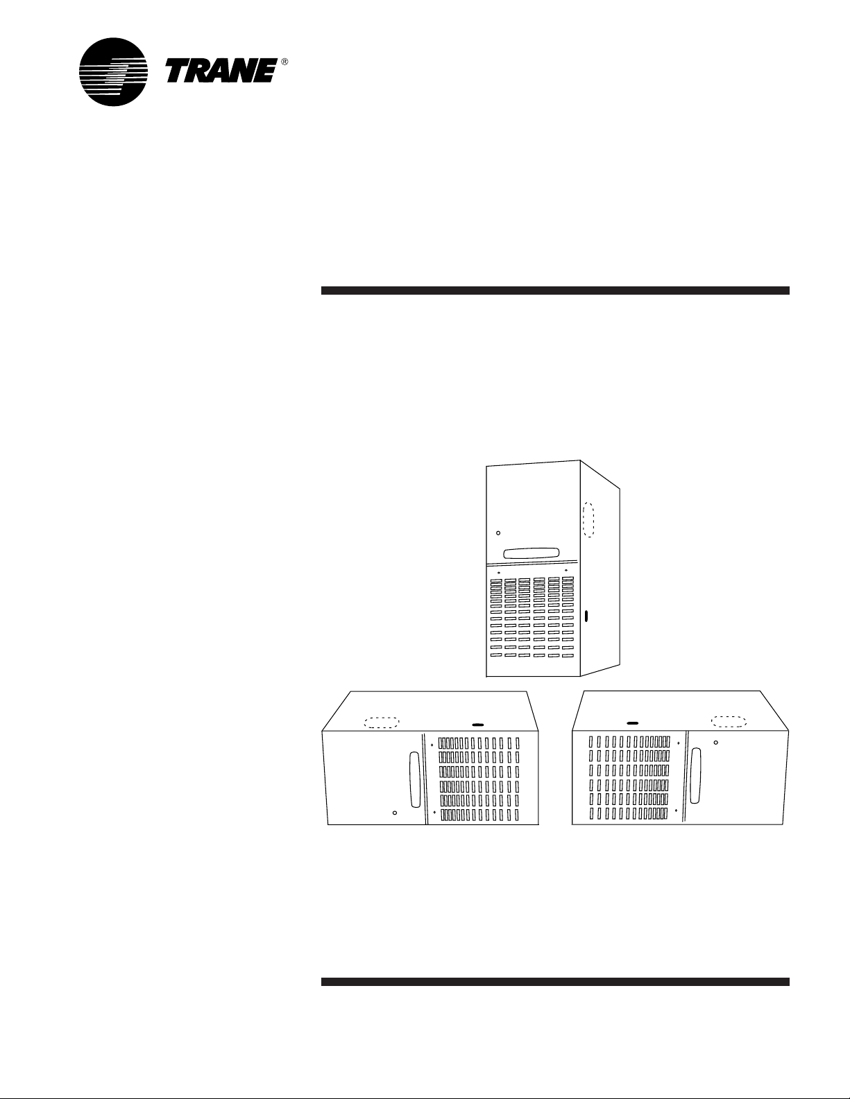
TDD-D-1
Downflow/Horizontal Right
or Downflow/Horizontal Left
Induced Draft Gas Furnace
XR 80
TDD040,060,080,100,120,140C
Single-Stage Fan Assisted
Combustion System
PUB. NO. 22-1671-04-0702 (EN)
Page 2

General Features
Natural Gas Models
Central Heating furnace designs are
certified by the American and Canadian
Gas Associations for both natural and
L.P. gas. Limit setting and rating data
were established and approved under
standard rating conditions using
American National Standards Institute
standards.
Safe Operation
The Integrated System Control has solid
state devices, which continuously monitor
for presence of flame, when the system is
in the heating mode of operation. Dual
solenoid combination gas valve and
regulator provide extra safety.
Quick Heating
Durable, cycle tested, heavy gauge
aluminized steel heat exchanger
quickly transfers heat to provide warm
conditioned air to the structure.
Burners
Multi-port In-shot burners will give years
of quiet and efficient service. All models
can be converted to L.P. gas.
Integrated System Control
Exclusively designed operational program provides total control of furnace
limit sensors, blowers, gas valve, flame
control and includes self-diagnostics for
ease of service. Also contains connection points for E.A.C./humidifier.
Air Delivery
The 4-speed, direct drive blower motor,
has sufficient airflow for most heating and
cooling requirements, will switch from
heating to cooling speeds on demand
from room thermostat. The blower door
safety switch will prevent or terminate
furnace operation when the blower door
is removed.
Styling
Heavy gauge steel and “wrap-around”
cabinet construction is used in the
cabinet with baked-on enamel finish for
strength and beauty. The heat
exchanger section of the cabinet is
completely lined with foil faced fiberglass
insulation. This results in quiet and
efficient operation due to the excellent
acoustical and insulating qualities of
fiberglass.
Features and
General Operation
The XR 80 High Efficiency Gas Furnace
employs an adaptive Hot Surface Ignition
system, which eliminates the waste of a
constant burning pilot. The integrated
system control lights the main burners
upon a demand for heat from the room
thermostat. Complete front service
access.
a. Low energy power venter
b. Vent proving pressure switch.
© 2002 American Standard Inc. All Rights Reserved 2 22-1671-04-0702 (EN)
Page 3

Contents
General Features 2
Features and Benefits 4
Standard Equipment 4
Optional Equipment 5
General Data 6
TDD040C924F 6
TDD060C924F 6
TDD060C936F 6
TDD080C936F 7
TDD080C945F 7
TDD100C945F 7
TDD100C948F 8
TDD100C954F 8
TDD120C954F 8
TDD120C960F 9
TDD140C960F 9
Performance Data 10
Electrical Data 12
Field Wiring 13
Dimensions 15
22-1671-04-0702 (EN) 3
Page 4

Features and Benefits
XR 80 Downflow/Horizontal Right or Left
Standard Equipment
• Power supply 115/1/60
• Multi-port In-shot burners
• Integrated solid state control with selfdiagnostics
• Silicon Nitride hot surface igniter with
adaptive heat up
• Complete front service access
• Heavy gauge aluminized steel heat
exchanger
• Slide out blower assembly
• Blower door safety switch
• Direct drive, 4-speed motor
• Cleanable high velocity filters
• Optional L.P. conversion kit
• Common vent
• Left and right side knockout for venting
• Selectable cooling fan off delay
eliminates need for BAY24X045 time
delay relay
• Quiet slow opening gas valve
• Downflow convertible to horizontal on
left or right side
• Insulated blower door
• Insulated blower compartment
• Accessory hook-up capability –
Hum and EAC
• Quiet induced draft blower
• Blower door safety switch
• Left/right gas connection
• 24 volt fuse
• Manual reset burner box limit
• Non-prorated 20-year heat
exchanger limited warranty
• 5-year limited parts warranty
4 22-1671-04-0702 (EN)
Page 5

Features and
Benefits
Optional Equipment
Thermostat ............................................................................................................................................................... BAYSTAT388 [ ]
Thermostat, Heating/Cooling Single Stage (Mounts Horizontally) .................................................................................. AY28X092 [ ]
Thermostat, Heating/Cooling Single Stage (Mounts Vertically) ................................................................................. BAYSTAT305 [ ]
Thermostat, Electronic Programmable 1-Stage Heating/1-Stage Cooling ............................................................... TAYSTAT300C [ ]
Propane Conversion Kit .......................................................................................................................................... BAYLPKT210A [ ]
Electronic Air Filter, “Perfect Fit” Super Efficiency (14-1/2" Wide Gas Furnace) .......................................................TFE145A9FR1 [ ]
Electronic Air Filter, “Perfect Fit” Super Efficiency (17-1/2" Wide Gas Furnace) .......................................................TFE175A9FR1 [ ]
Electronic Air Filter, “Perfect Fit” Super Efficiency (21" Wide Gas Furnace) ............................................................. TFE210A9FR1 [ ]
Electronic Air Filter, “Perfect Fit” Super Efficiency (24-1/2" Wide Gas Furnace) .......................................................TFE245A9FR1 [ ]
Electronic Air Filter, “Perfect Fit” High Efficiency (14-1/2" Wide Gas Furnace) ........................................................ TFM145A9FR1 [ ]
Electronic Air Filter, “Perfect Fit” High Efficiency (17-1/2" Wide Gas Furnace) ........................................................ TFM175A9FR1 [ ]
Electronic Air Filter, “Perfect Fit” High Efficiency (21" Wide Gas Furnace) .............................................................. TFM210A9FR1 [ ]
Electronic Air Filter, “Perfect Fit” High Efficiency (24-1/2" Wide Gas Furnace) ........................................................ TFM245A9FR1 [ ]
Electronic Air Filter, “Perfect Fit” Standard Efficiency (17-1/2" Wide Gas Furnace) ................................................ TFP175A9FR01 [ ]
Electronic Air Filter, “Perfect Fit” Standard Efficiency (21" Wide Gas Furnace) ...................................................... TFP210A9FR01 [ ]
Electronic Air Filter, “Perfect Fit” Standard Efficiency (24-1/2" Wide Gas Furnace) ................................................ TFP245A9FR01 [ ]
Coil Enclosure (14-1/2" Wide Cabinets) ................................................................................................................. BAYCLE1400C [ ]
Coil Enclosure (17-1/2" Wide Cabinets) ................................................................................................................. BAYCLE1700C [ ]
Coil Enclosure (21" Wide Cabinets) ....................................................................................................................... BAYCLE2100C [ ]
Coil Enclosure (24-1/2" Wide Cabinets) ................................................................................................................. BAYCLE2400C [ ]
Filter Access Door Kit ............................................................................................................................................... BAYFLTR206 [ ]
Downflow Subbase .................................................................................................................................................. BAYBASE205 [ ]
High Altitude Pressure Switch Kit .............................................................................................................................. BAYHALT248 [ ]
22-1671-04-0702 (EN) 5
Page 6

General Data
Product Specifications 1
MODEL
TYPE
RATINGS 2
Input BTUH
Capacity BTUH (ICS) 3
AFUE
Temp. rise (Min.-Max.) °F.
BLOWER DRIVE
Diameter - Width (In.)
No. Used
Speeds (No.)
CFM vs. in. w.g.
Motor HP
R.P.M.
Volts / Ph / Hz
COMBUSTION FAN - Type
Drive - No. Speeds
Motor HP - RPM
Volts / Ph / Hz
FLA
FILTER — Furnished?
Type Recommended
Hi Vel. (No.-Size-Thk.)
VENT — Size (in.)
HEAT EXCHANGER
Type -Fired
-Unfired
Gauge (Fired)
ORIFICES — Main
Nat. Gas. Qty. — Drill Size
L.P. Gas Qty. — Drill Size
GAS VALVE
PILOT SAFETY DEVICE
Type
BURNERS — Type
Number
POWER CONN. — V / Ph / Hz 4
Ampacity (In Amps)
Max. Overcurrent Protection (Amps)
PIPE CONN. SIZE (IN.)
DIMENSIONS
Crated (In.)
WEIGHT
Shipping (Lbs.) / Net (Lbs)
1 Central Furnace heating designs are certified by AGA and CSA.
2 For U.S. applications, above input ratings (BTUH) are up to 2,000 ft., derate 4% per 1,000 ft. for elevations above 2,000 ft. above sea level.
For Canadian applications, above input ratings (BTUH) are up to 4,500 ft., derate 4% per 1,000 ft. for elevations above 4,500 ft. above sea level.
3 Based on U.S. government standard tests.
4 The above wiring specifications are in accordance with National Electrical Code; however, installations must comply with local codes.
TDD040C924F
Downflow / Horizontal
40,000
31,000
80.0
30 - 60
DIRECT
10 x 6
1
4
See Fan Performance Table
1/5
1075
115/1/60
Centrifugal
Direct - 1
1/50 - 3000
115/1/60
1.0
Yes
High Velocity
2 - 14x20 - 1in.
4 Round
Aluminized Steel - Type I
20
2 — 45
2 — 56
Redundant - Single Stage
Hot Surface Ignition
Multi-port In-shot
2
115/1/60
5.2
10
1/2
H x W x D
41 x 15-1/2 x 29-1/2
119 / 109
TDD060C924F
Downflow / Horizontal
60,000
48,000
80.0
35 - 65
DIRECT
10 x 7
1
4
See Fan Performance Table
1/5
1075
115/1/60
Centrifugal
Direct - 1
1/50 - 3000
115/1/60
1.0
Yes
High Velocity
2 - 14x20 - 1in.
4 Round
Aluminized Steel - Type I
20
3 — 45
3 — 56
Redundant - Single Stage
Hot Surface Ignition
Multi-port In-shot
3
115/1/60
5.2
15
1/2
H x W x D
41 x 15-1/2 x 29-1/2
129 / 119
TDD060C936F
Downflow / Horizontal
60,000
48,000
80.0
30 - 60
DIRECT
11 x 7
1
4
See Fan Performance Table
1/2
1075
115/1/60
Centrifugal
Direct - 1
1/50 - 3000
115/1/60
1.0
Yes
High Velocity
2 - 14x20 - 1in.
4 Round
Aluminized Steel - Type I
20
3 — 45
3 — 56
Redundant - Single Stage
Hot Surface Ignition
Multi-port In-shot
3
115/1/60
11.2
15
1/2
H x W x D
41 x 15-1/2 x 29-1/2
129 / 119
6 22-1671-04-0702 (EN)
Page 7

General
Data
Product Specifications 1
MODEL
TYPE
RATINGS 2
Input BTUH
Capacity BTUH (ICS) 3
AFUE
Temp. rise (Min.-Max.) °F.
BLOWER DRIVE
Diameter - Width (In.)
No. Used
Speeds (No.)
CFM vs. in. w.g.
Motor HP
R.P.M.
Volts / Ph / Hz
COMBUSTION FAN - Type
Drive - No. Speeds
Motor HP - RPM
Volts / Ph / Hz
FLA
FILTER — Furnished?
Type Recommended
Hi Vel. (No.-Size-Thk.)
VENT — Size (in.)
HEAT EXCHANGER
Type -Fired
-Unfired
Gauge (Fired)
ORIFICES — Main
Nat. Gas. Qty. — Drill Size
L.P. Gas Qty. — Drill Size
GAS VALVE
PILOT SAFETY DEVICE
Type
BURNERS — Type
Number
POWER CONN. — V / Ph / Hz 4
Ampacity (In Amps)
Max. Overcurrent Protection (Amps)
PIPE CONN. SIZE (IN.)
DIMENSIONS
Crated (In.)
WEIGHT
Shipping (Lbs.) / Net (Lbs)
1 Central Furnace heating designs are certified by AGA and CSA.
2 For U.S. applications, above input ratings (BTUH) are up to 2,000 ft., derate 4% per 1,000 ft. for elevations above 2,000 ft. above sea level.
For Canadian applications, above input ratings (BTUH) are up to 4,500 ft., derate 4% per 1,000 ft. for elevations above 4,500 ft. above sea level.
3 Based on U.S. government standard tests.
4 The above wiring specifications are in accordance with National Electrical Code; however, installations must comply with local codes.
TDD080C936F
Downflow / Horizontal
80,000
64,000
80.0
35 - 65
DIRECT
10 x 7
1
4
See Fan Performance Table
1/3
1075
115/1/60
Centrifugal
Direct - 1
1/50 - 3000
115/1/60
1.0
Yes
High Velocity
2 - 14x20 - 1in.
4 Round
Aluminized Steel - Type I
20
4 — 45
4 — 56
Redundant - Single Stage
Hot Surface Ignition
Multi-port In-shot
4
115/1/60
8.5
10
1/2
H x W x D
41 x 18-1/2 x 29-1/2
146 / 135
TDD080C945F
Downflow / Horizontal
80,000
64,000
80.0
35 - 65
DIRECT
10 x 8
1
4
See Fan Performance Table
1/3
1075
115/1/60
Centrifugal
Direct - 1
1/50 - 3000
115/1/60
1.0
Yes
High Velocity
2 - 16x20 - 1in.
4 Round
Aluminized Steel - Type I
20
4 — 45
4 — 56
Redundant - Single Stage
Hot Surface Ignition
Multi-port In-shot
4
115/1/60
9.1
10
1/2
H x W x D
41 x 18-1/2 x 29-1/2
146 / 135
TDD100C945F
Downflow / Horizontal
100,000
80,000
80.0
35 - 65
DIRECT
10 x 8
1
4
See Fan Performance Table
1/3
1075
115/1/60
Centrifugal
Direct - 1
1/50 - 3200
115/1/60
1.0
Yes
High Velocity
2 - 16x20 - 1in.
4 Round
Aluminized Steel - Type I
20
5 — 45
5 — 56
Redundant - Single Stage
Hot Surface Ignition
Multi-port In-shot
5
115/1/60
9.1
10
1/2
H x W x D
41 x 18-1/2 x 29-1/2
156 / 145
22-1671-04-0702 (EN) 7
Page 8

General
Data
Product Specifications 1
MODEL
TYPE
RATINGS 2
Input BTUH
Capacity BTUH (ICS) 3
AFUE
Temp. rise (Min.-Max.) °F.
BLOWER DRIVE
Diameter - Width (In.)
No. Used
Speeds (No.)
CFM vs. in. w.g.
Motor HP
R.P.M.
Volts / Ph / Hz
COMBUSTION FAN - Type
Drive - No. Speeds
Motor HP - RPM
Volts / Ph / Hz
FLA
FILTER — Furnished?
Type Recommended
Hi Vel. (No.-Size-Thk.)
VENT — Size (in.)
HEAT EXCHANGER
Type -Fired
-Unfired
Gauge (Fired)
ORIFICES — Main
Nat. Gas. Qty. — Drill Size
L.P. Gas Qty. — Drill Size
GAS VALVE
PILOT SAFETY DEVICE
Type
BURNERS — Type
Number
POWER CONN. — V / Ph / Hz 4
Ampacity (In Amps)
Max. Overcurrent Protection (Amps)
PIPE CONN. SIZE (IN.)
DIMENSIONS
Crated (In.)
WEIGHT
Shipping (Lbs.) / Net (Lbs)
1 Central Furnace heating designs are certified by AGA and CSA.
2 For U.S. applications, above input ratings (BTUH) are up to 2,000 ft., derate 4% per 1,000 ft. for elevations above 2,000 ft. above sea level.
For Canadian applications, above input ratings (BTUH) are up to 4,500 ft., derate 4% per 1,000 ft. for elevations above 4,500 ft. above sea level.
3 Based on U.S. government standard tests.
4 The above wiring specifications are in accordance with National Electrical Code; however, installations must comply with local codes.
TDD100C948F
Downflow / Horizontal
100,000
80,000
80.0
35 - 65
DIRECT
10 x 8
1
4
See Fan Performance Table
1/2
1075
115/1/60
Centrifugal
Direct - 1
1/50 - 3000
115/1/60
1.0
Yes
High Velocity
2 - 16x20 - 1in.
4 Round
Aluminized Steel - Type I
20
5 — 45
5 — 56
Redundant - Single Stage
Hot Surface Ignition
Multi-port In-shot
5
115/1/60
14.2
15
1/2
H x W x D
41 x 22 x 29-1/2
166 / 154
TDD100C954F
Downflow / Horizontal
100,000
81,000
80.0
30 - 60
DIRECT
11 x 10
1
4
See Fan Performance Table
1/2
1075
115/1/60
Centrifugal
Direct - 1
1/50 - 3000
115/1/60
1.0
Yes
High Velocity
2 - 14x20 - 1in.
4 Round
Aluminized Steel - Type I
20
5 — 45
5 — 56
Redundant - Single Stage
Hot Surface Ignition
Multi-port In-shot
5
115/1/60
12.8
15
1/2
H x W x D
41 x 22 x 29-1/2
167 / 155
TDD120C954F
Downflow / Horizontal
120,000
96,000
80.0
35 - 65
DIRECT
11 x 10
1
4
See Fan Performance Table
1/2
1075
115/1/60
Centrifugal
Direct - 1
1/50 - 3000
115/1/60
1.0
Yes
High Velocity
2 - 16x20 - 1in.
4 Round
Aluminized Steel - Type I
20
6 — 45
6 — 56
Redundant - Single Stage
Hot Surface Ignition
Multi-port In-shot
6
115/1/60
12.8
15
1/2
H x W x D
41 x 22 x 29-1/2
170 / 158
8 22-1671-04-0702 (EN)
Page 9

General
Data
Product Specifications 1
MODEL
TYPE
RATINGS 2
Input BTUH
Capacity BTUH (ICS) 3
AFUE
Temp. rise (Min.-Max.) °F.
BLOWER DRIVE
Diameter - Width (In.)
No. Used
Speeds (No.)
CFM vs. in. w.g.
Motor HP
R.P.M.
Volts / Ph / Hz
COMBUSTION FAN - Type
Drive - No. Speeds
Motor HP - RPM
Volts / Ph / Hz
FLA
FILTER — Furnished?
Type Recommended
Hi Vel. (No.-Size-Thk.)
VENT — Size (in.)
HEAT EXCHANGER
Type -Fired
-Unfired
Gauge (Fired)
ORIFICES — Main
Nat. Gas. Qty. — Drill Size
L.P. Gas Qty. — Drill Size
GAS VALVE
PILOT SAFETY DEVICE
Type
BURNERS — Type
Number
POWER CONN. — V / Ph / Hz 4
Ampacity (In Amps)
Max. Overcurrent Protection (Amps)
PIPE CONN. SIZE (IN.)
DIMENSIONS
Crated (In.)
WEIGHT
Shipping (Lbs.) / Net (Lbs)
1 Central Furnace heating designs are certified by AGA and CSA.
2 For U.S. applications, above input ratings (BTUH) are up to 2,000 ft., derate 4% per 1,000 ft. for elevations above 2,000 ft. above sea level.
For Canadian applications, above input ratings (BTUH) are up to 4,500 ft., derate 4% per 1,000 ft. for elevations above 4,500 ft. above sea level.
3 Based on U.S. government standard tests.
4 The above wiring specifications are in accordance with National Electrical Code; however, installations must comply with local codes.
TDD120C960F
Downflow / Horizontal
120,000
96,000
80.0
35 - 65
DIRECT
11 x 10
1
4
See Fan Performance Table
1/2
1075
115/1/60
Centrifugal
Direct - 1
1/50 - 3000
115/1/60
1.0
Yes
High Velocity
2 - 16x20 - 1in.
4 Round
Aluminized Steel - Type I
20
6 — 45
6 — 56
Redundant - Single Stage
Hot Surface Ignition
Multi-port In-shot
6
115/1/60
12.8
15
1/2
H x W x D
41 x 25-1/2 x 29-1/2
189 / 176
TDD140C960F
Downflow / Horizontal
140,000
113,000
80.0
45 - 75
DIRECT
11 x 10
1
4
See Fan Performance Table
3/4
1075
115/1/60
Centrifugal
Direct - 1
1/50 - 3000
115/1/60
1.0
Yes
High Velocity
2 - 16x20 - 1in.
4 Round
Aluminized Steel - Type I
20
7 — 45
7 — 56
Redundant - Single Stage
Hot Surface Ignition
Multi-port In-shot
7
115/1/60
13.1
15
1/2
H x W x D
41 x 25-1/2 x 29-1/2
196 / 183
22-1671-04-0702 (EN) 9
Page 10

Performance Data
FURNACE AIRFLOW (CFM) VS. STATIC PRESSURE (ins. w.g.)
MODEL SPEED TAP 0.100.200.300.400.500.600.700.800.90
TDD040C924F
TDD060C924F
TDD060C936F
TDD080C936F
TDD080C945F
TDD100C945F
HIGH - Black
4 -
MED.-HIGH - Blue
3 -
MED.-LOW - Yellow
2 -
LOW - Red
1 -
HIGH - Black
4 -
MED.-HIGH - Blue
3 -
MED.-LOW - Yellow
2 -
LOW - Red
1 -
HIGH - Black
4 -
MED.-HIGH - Blue
3 -
MED.-LOW - Yellow
2 -
LOW - Red
1 -
HIGH - Black
4 -
MED.-HIGH - Blue
3 -
MED.-LOW - Yellow
2 -
LOW - Red
1 -
HIGH - Black
4 -
MED.-HIGH - Blue
3 -
MED.-LOW - Yellow
2 -
LOW - Red
1 -
HIGH - Black
4 -
MED.-HIGH - Blue
3 -
MED.-LOW - Yellow
2 -
LOW - Red
1 -
1070
870
740
633
1200
1025
838
722
1480
1302
1115
956
1523
1317
1123
942
1798
1384
1210
1005
1767
1382
1130
840
1033
850
720
600
1155
988
808
689
1429
1276
1100
947
1496
1307
1119
943
1750
1367
1150
970
1731
1354
1138
831
1000
823
690
577
1111
951
779
656
1375
1229
1070
918
1463
1261
1106
931
1692
1333
1108
808
1669
1323
1115
815
960
790
663
543
1056
905
742
618
1318
1188
1035
888
1420
1242
1082
920
1642
1300
1075
775
1615
1292
1085
792
920
753
627
507
1001
859
704
579
1282
1141
1000
859
1369
1223
1056
898
1575
1275
1042
767
1546
1254
1054
762
860
813
588
463
924
797
646
528
1100
1088
965
824
1310
1175
1016
868
1500
1233
1008
733
1469
1207
1015
731
810
667
547
420
848
735
588
478
1112
1024
918
788
1243
1122
976
833
1425
1192
967
700
1392
1177
977
700
740
613
483
360
774
646
502
376
1029
953
859
741
1172
1060
930
795
1325
1142
925
675
1300
1108
938
654
-
490
-
-
701
558
415
275
959
882
790
682
1100
1000
880
760
1225
1083
867
617
1146
1038
877
625
TDD100C948F
TDD100C954F
TDD120C954F
TDD120C960F
TDD140C960F
HIGH - Black
4 -
MED.-HIGH - Blue
3 -
MED.-LOW - Yellow
2 -
LOW - Red
1 -
HIGH - Black
4 -
MED.-HIGH - Blue
3 -
MED.-LOW - Yellow
2 -
LOW - Red
1 -
HIGH - Black
4 -
MED.-HIGH - Blue
3 -
MED.-LOW - Yellow
2 -
LOW - Red
1 -
HIGH - Black
4 -
MED.-HIGH - Blue
3 -
MED.-LOW - Yellow
2 -
LOW - Red
1 -
HIGH - Black
4 -
MED.-HIGH - Blue
3 -
MED.-LOW - Yellow
2 -
LOW - Red
1 -
1965
1645
1407
1202
2165
1962
1705
1492
2241
1981
1721
1476
2241
1981
1721
1476
2377
2115
1806
1527
1915
1627
1398
1208
2113
1927
1688
1467
2202
1962
1705
1466
2202
1962
1705
1466
2321
2081
1793
1507
1865
1605
1387
1205
2060
1891
1671
1442
2163
1942
1688
1456
2163
1942
1688
1456
2265
2046
1779
1486
10 22-1671-04-0702 (EN)
1805
1575
1375
1195
1995
1839
1636
1414
2106
1904
1671
1440
2106
1904
1671
1440
2199
1992
1738
1473
1740
1535
1347
1166
1929
1786
1600
1385
2049
1866
1653
1423
2049
1866
1653
1423
2133
1938
1696
1459
1670
1482
1318
1140
1842
1724
1547
1346
1979
1805
1611
1392
1979
1805
1611
1392
2050
1872
1655
1422
1587
1421
1275
1105
1755
1662
1492
1307
1908
1743
1569
1361
1908
1743
1569
1361
1967
1805
1614
1384
1500
1330
1190
1045
1674
1581
1435
1243
1804
1680
1515
1302
1804
1680
1515
1302
1877
1727
1556
1329
1370
1220
1095
970
1593
1500
1377
1179
1700
1617
1461
1243
1700
1617
1461
1243
1786
1649
1497
1273
Page 11

MODEL
Performance
Data
CFM VS. TEMPERATURE RISE
Cubic Feet Per Minute (CFM)
500 600 700 800 900 1000 1100 1200 1300 1400 1500 1600 1700 1800 1900 2000 2100 2200 2300 2400
TDD040C924F
TDD060C924F
TDD060C936F
TDD80C936F
TDD80C945F
TDD100C945F
TDD100C9484F
TDD100C954F
TDD120C954F 59 56 52 49 47 44 42 40
TDD120C960F
TDD140C960F 69 65 61 58 55 52 49 47 45
59 49 42 37 33 30
63 56 49 44 40
56 49 44 40 37 34 32
59 54 59 46 42
64 57 52 48 44 41
62 57 53 49 46 44 41
62 57 53 49 46 44 41 39 37
62 57 53 49 46 44 41 39 37 35 34 32 31
59 56 52 49 47 44 42 40
22-1671-04-0702 (EN) 11
Page 12

Electrical Data
SCHEMATIC DIAGRAMS FOR GAS FURNACES
From Dwg. 21D341705 Rev. 0
12 22-1671-04-0702 (EN)
Page 13

Field Wiring
FIELD WIRING DIAGRAM FOR SINGLE STAGE HEATING ONLY
From Dwg. 21B341437 Rev. 1
FIELD WIRING DIAGRAM FOR SINGLE STAGE HEATING/COOLING
(OUTDOOR SECTION WITHOUT TRANSFORMER)
22-1671-04-0702 (EN) 13
From Dwg. 21B341436 Rev. 1
Page 14

Field
Wiring
From Dwg. 21B341422 Rev. 1
From Dwg. 21B341423 Rev. 1
14 22-1671-04-0702 (EN)
Page 15

Dimensions
From Dwg. 21C341700 Rev. 0
(ALL DIMENSIONS ARE IN INCHES)
TDD-C OUTLINE DRAWING
22-1671-04-0702 (EN) 15
Page 16

Literature Order Number TDD-D-1
File Number PL-UN-FURN-TDD-D-1
Supersedes TDD-D-1 3/98
Stocking Location PI Louisville & Webb/Mason-Houston 7/02
P.I.
The Trane Company
An American Standard Company
www.trane.com
Since The Trane Company has a policy of continuous product and product data improvement, it reserves the
right to change design and specifications without notice.
 Loading...