

Page 1
TRAK® 3ntr 3D Printers
Printer & MMS Operation Quick Start Guide
Covers Current Models:
• 3ntr A2
• 3ntr A4
• 3ntr MMS v1/v2
2615 Homestead Place
Rancho Dominguez, CA 90220-5610 USA
T | 310.608.4422 | F | 310.764.2668
Service Department: 800.367.3165
e-mail: [email protected] | [email protected] | web: www.trakmt.com
Document: P/N 32236
Version: 111919
Page 2

Copyright © 2019, Southwestern Industries, Inc. All rights are reserved. No part of this publication may
be reproduced, stored in a retrieval system, or transmitted, in any form or by any means, mechanical,
photocopying, recording or otherwise, without the prior written permission of Southwestern Industries,
Inc.
While every effort has been made to include all the information required for the purposes of this guide,
Southwestern Industries, Inc. assumes no responsibility for inaccuracies or omission and accepts no
liability for damages resulting from the use of the information contained in this guide.
All brand names and products are trademarks or registered trademarks of their respective holders.
Southwestern Industries, Inc.
2615 Homestead Place
Rancho Dominguez, CA 90220
Phone 310-608-4422 Fax 310-764-2668
Service Department
Phone 800-367-3165 Fax 310-886-8029
Page 3

i
TRAK Machine Tools
Southwestern Industries, Inc.
TRAK 3ntr 3D Printers – Printer & MMS Operation Quick Start Guide
Table of Contents
1 Introduction ............................................................... 1
1.1 Operation Quick Start Guide Scope ...................................................... 1
1.2 Procedures/Instructions Overview ...................................................... 2
2 Safety.......................................................................... 3
2.1 Safety Precautions ................................................................................ 3
3 Printer Orientation ...................................................... 5
3.1 Printer Identification Guide: Front, Rear, and Side Views ................... 5
3.2 Front Panel Controls ............................................................................. 7
4 Check & Fill Coolant Level........................................... 8
5 Power on the Printer and MMS Unit (If applicable) .... 9
5.1 Power on the MMS Unit (If applicable) ................................................ 9
5.2 Power on the Printer ............................................................................. 9
6 Manual Printer Operation via Front Panel Controls ..10
6.1 LCD Display and Control Menus Overview ......................................... 10
6.1.1 LCD Display – Idle Machine Menu ................................................ 10
6.1.2 LCD Display – Information Screen ................................................ 10
6.1.3 LCD Display – Prepare Menu ......................................................... 11
6.2 Operate the Printer Manually with LCD/Front Panel Controls ........... 11
6.2.1 Move Axis Function ....................................................................... 11
6.2.2 Auto Home Function ..................................................................... 14
6.2.3 Disable Steppers ........................................................................... 15
7 Load Filament/Materials ...........................................16
7.1 Load Filament to Back of Printer ........................................................ 16
7.2 Loading Filament/Material into the MMS Unit ................................... 22
7.3 Filament Care/Storage ....................................................................... 23
8 Purge Nozzle/Filament .............................................26
9 Clean Nozzles ............................................................29
Page 4

ii
TRAK Machine Tools
Southwestern Industries, Inc.
TRAK 3ntr 3D Printers – Printer & MMS Operation Quick Start Guide
9.1 Clean Nozzle Procedure Overview: ..................................................... 29
9.2 Unload Filament Using Change Filament Function ............................. 29
9.3 Load Cleaning Filament ...................................................................... 33
9.4 Nozzle Cleaning (Automated Function) .............................................. 35
10 MMS Unit Operation ..................................................38
10.1 MMS Overview .................................................................................... 38
10.2 Power ON the MMS Unit ..................................................................... 38
10.3 MMS Touch Screen Control ................................................................. 38
10.4 MMS Dashboard .................................................................................. 38
10.4.1 Accessing the MMS Dashboard over a network ............................ 40
11 Print Parts from an SD Card ......................................41
11.1 Stop/Pause Printing ........................................................................... 44
11.2 Tune Menu – Adjust Process Parameters Mid-Print ........................... 44
12 Remove a Printed Part from the Printer ...................46
13 Print Server Overview ...............................................48
14 Maintain your printer for subsequent prints .............49
15 TRAK Warranty Policy ...............................................50
Page 5

1
TRAK Machine Tools
Southwestern Industries, Inc.
TRAK 3ntr 3D Printers – Printer & MMS Operation Quick Start Guide
1 Introduction
Congratulations! Whether you purchased a TRAK 3ntr A2 or A4, you have an industrial-grade, 3D printer
that will produce high quality, functional parts, using an accurate and repeatable FFF print process, at low
cost per part.
TRAK 3ntr 3D Printers offer:
• An open materials platform enabling selection of a wide range of materials
• Complete flexibility in tailoring/tuning process settings and part characteristics
• Temperature controlled build chambers and printer plates
o Nozzles up to 840° F (450°C)
o Bed Up to 320° F (160° C)
o Chamber up to 194° F (90° C)
• Generous build capacity/volume
o Print Parts up to 24”x13”x19” for the A2
o Print Parts up to 12”x7.5”x 8” for the A4
• Simultaneously prints 2 or 3 different print materials
• Integrated camera offering remote web monitoring
• Optional Material Management System to protect expensive environmentally sensitive materials
• KISSlicer software that converts STL files to printer ready g-code programs
1.1 Operation Quick Start Guide Scope
This Quick Start Guide covers the basic steps required to operate your new TRAK 3ntr A2/A4 printer and
MMS unit including printing. It covers a limited scope of operation for the A2/A4 printer and MMS unit,
as necessary for initial familiarization and printing simple parts that do not require extensive printer or
extruder reconfiguration. For procedure instructions not contained within this Quick Start Guide, please
consult the Printer & MMS Guide before proceeding.
IMPORTANT – This Quick Start Guide assumes the printer has been initially set-up, calibrated and
printed test parts by a qualified, factory, trained technician or otherwise in accordance with the TRAK
3ntr A2/A4 Printer & MMS Installation, Set-Up, and Calibration Guide or Printer & MMS Guide documents.
If these steps have not been completed, or the printer/MMS unit are not functioning normally, STOP !
Consult the printer & MMS guide or installation, set-up, and calibration guide as applicable before
proceeding.
CAUTION - Section 2 contains important safety information, it is highly recommended that all personnel
and operators review and understand this information before starting. Only qualified and trained
operators should use this Quick Start Guide.
Page 6

2
TRAK Machine Tools
Southwestern Industries, Inc.
TRAK 3ntr 3D Printers – Printer & MMS Operation Quick Start Guide
1.2 Procedures/Instructions Overview
Figure 1.2.1 below clarifies the subset of operational procedures and instructions included within this
Quick Start Guide. Click the hyper link to jump to individual procedure instructions. There are many
more, not contained within this abbreviated guide. For other procedures/instructions, or additional detail,
please consult the (full) Printer & MMS Guide, Maintenance Manual, or individual procedure work
instruction documents.
Procedure Name/Instruction
Safety Precautions
Printer Identification Guide
Front Panel Controls
Check & Fill Coolant Level
Power on Printer and MMS Unit (if applicable)
Operate the Printer Manually with LCD/Front Panel Controls
Load Filament/Materials to Printer/MMS Unit
Filament Care & Storage
Purge Nozzles/Filament
Clean Nozzles
Print Parts from an SD Card
Remove a printed part from the Printer
MMS Unit Operation
Print Server Overview
Maintain your Printer for Subsequent Prints
Figure 1.2.1 List of Procedures within this QS Operations Guide
CAUTION – Do not perform any operation/printer re-configuration/maintenance, or repair without
consulting and following the instructions from a factory guide or work instruction document. Contact
customer service for proper documentation before proceeding - Failure to do so may damage the printer,
result in injury, and/or void the warranty.
Page 7

3
TRAK Machine Tools
Southwestern Industries, Inc.
TRAK 3ntr 3D Printers – Printer & MMS Operation Quick Start Guide
2 Safety
The safe set-up, calibration, and operation of your TRAK 3ntr 3D printer depends on its proper use and
precautions taken by each operator. If these activities are performed incorrectly, there are risks, not
limited to, electric shock, pinch/crush, burns, inhalation of fumes/debris that can cause serious injury or
death.
Read and follow this Quick Start Guide. Understand the printer operation and safety precautions before
setting up, calibrating, or operating the 3D printer.
• Always wear safety glasses and safety shoes.
• Always stop the printer before opening the access door and reaching into the printer.
• Always allow the printer, printer surface plate and workpiece to cool adequately before reaching
into the printer.
• Have a qualified electrician make all electrical connections and cable wiring
• Never wear gloves, rings, watches, long sleeves, neckties, jewelry, or other loose items when
operating the printer.
2.1 Safety Precautions
1) Do not operate this machine before the TRAK 3ntr Safety, Installation, Maintenance, Service and
Parts List Manual, and the Safety, Programming, Operating & Care Manual have been studied and
understood.
2) Do not run this machine without knowing the function of every control key, button, knob, or
handle. Ask your supervisor or a qualified instructor for help when needed.
3) Protect your eyes. Wear approved safety glasses (with side shields) at all times.
4) Allow the machine to cool before reaching into it for any reason. The printer bed, printer surface
plate, printed part, extruders/nozzles, and other printer interior components can reach very high
temperatures and cause serious burns.
5) Don't get caught in moving parts. Before operating this machine remove all jewelry including
watches and rings, neckties, and any loose-fitting clothing.
6) Keep your hair away from moving parts. Wear adequate safety headgear.
7) Protect your feet. Wear safety shoes with oil-resistant, anti-skid soles, and steel toes.
8) Take off gloves before you start the machine. Gloves are easily caught in moving parts.
9) Remove all tools (wrenches, check keys, etc.) from the machine before you start. Loose items
can become dangerous flying projectiles.
10) Never operate a 3D printer after consuming alcoholic beverages, or taking strong medication, or
while using non-prescription drugs.
11) Protect your hands. Stop the printer bed movement and extruder translation mechanism:
a. Before opening the printer access door
b. Before reaching into the machine for any reason
c. Before changing parts
d. Before removing the printer bed tray, printed parts, or filament debris
e. Before you make an adjustment to the extruder, nozzles or any interior mechanism.
12) Protect your eyes and the machine as well. Don't use a compressed air hose to remove the
debris or clean the machine.
13) Stop and disconnect the machine before you perform maintenance and calibration operations.
14) Keep work area well lighted. Ask for additional light if needed.
Page 8

4
TRAK Machine Tools
Southwestern Industries, Inc.
TRAK 3ntr 3D Printers – Printer & MMS Operation Quick Start Guide
15) Do not lean on the machine while it is running.
16) Prevent slippage. Keep the work area dry and clean. Remove obstacles of any kind around the
machine.
17) Avoid getting pinched in places where the printer bed or extruder arm movement can cause a
crush or pinch injury
18) Do not operate the printer with the printer access door open or any of the windows or service
access panels removed.
Page 9
5
TRAK Machine Tools
Southwestern Industries, Inc.
TRAK 3ntr 3D Printers – Printer & MMS Operation Quick Start Guide
3 Printer Orientation
In this section, you will meet your new TRAK 3ntr 3D printer. After uncrating, please take a moment to
identify the important components of the printer before starting the set-up process.
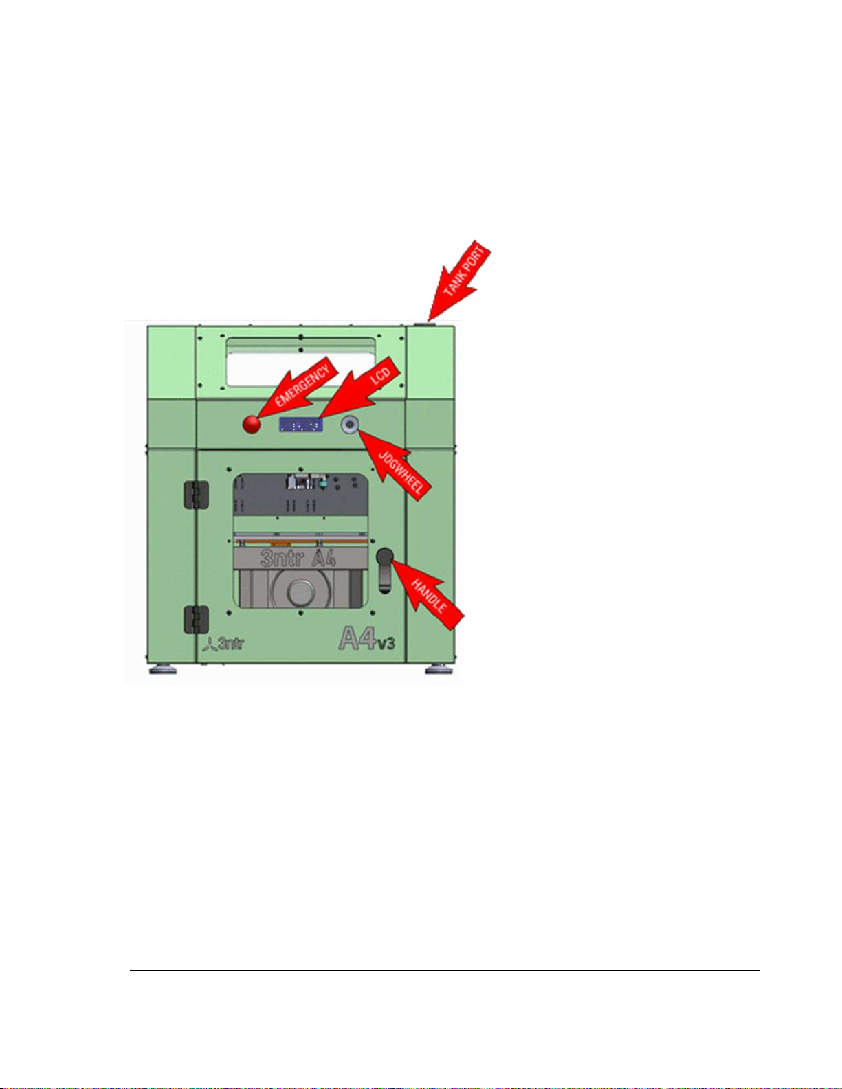
3.1 Printer Identification Guide: Front, Rear, and Side Views
1) Emergency -E-STOP
Button. Powers ON
and OFF the Printer
2) LCD Display – Use for
printer control and
printing information
3) Jog Wheel and Black
Selector Button
4) Printer Door – Locking
Handle
5) Tank Port – Coolant
Check & Fill Location
Figure 3.1.1 Printer Front View
Page 10
6
TRAK Machine Tools
Southwestern Industries, Inc.
TRAK 3ntr 3D Printers – Printer & MMS Operation Quick Start Guide
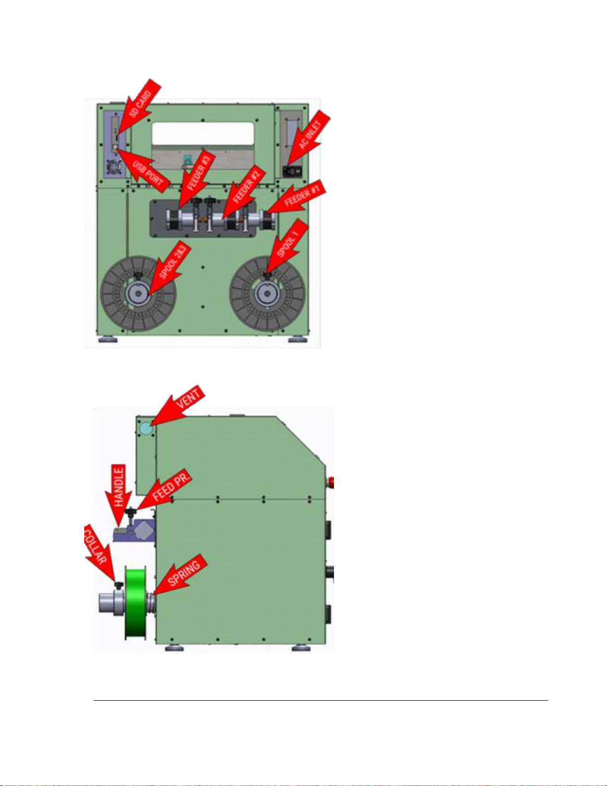
1) SD Card Port: Insert SD card
with print (g-code files).
2) USB Port for PC or Print Server
connection.
3) Filament Feeders – Feed
mechanism for extruders #1,
#2, #3.
4) AC Inlet – Printer Power Cord
plugs in here. Power On-OFF
switch.
5) Spool Holders – Filament
Spools are mounted here for
Extruders #1, #2, #3.
Figure 3.1.2 Printer Rear View
1) VENT – Print fume
extraction port. Remove
plate and install HEPA
filter elbow/hose here.
2) Feeder PR – Feeder
pressure knob, adjusts
filament feeder pressure.
3) Handle – engages or
releases filament feeder
(engaged position shown)
4) AC Inlet – Printer Power
Cord plugs in here.
Power On-OFF switch.
5) Collar – Filament Spools
are mounted here for
Extruders #1, #2, #3.
Figure 3.1.3 Printer Side View
Page 11
7
TRAK Machine Tools
Southwestern Industries, Inc.
TRAK 3ntr 3D Printers – Printer & MMS Operation Quick Start Guide
3.2 Front Panel Controls
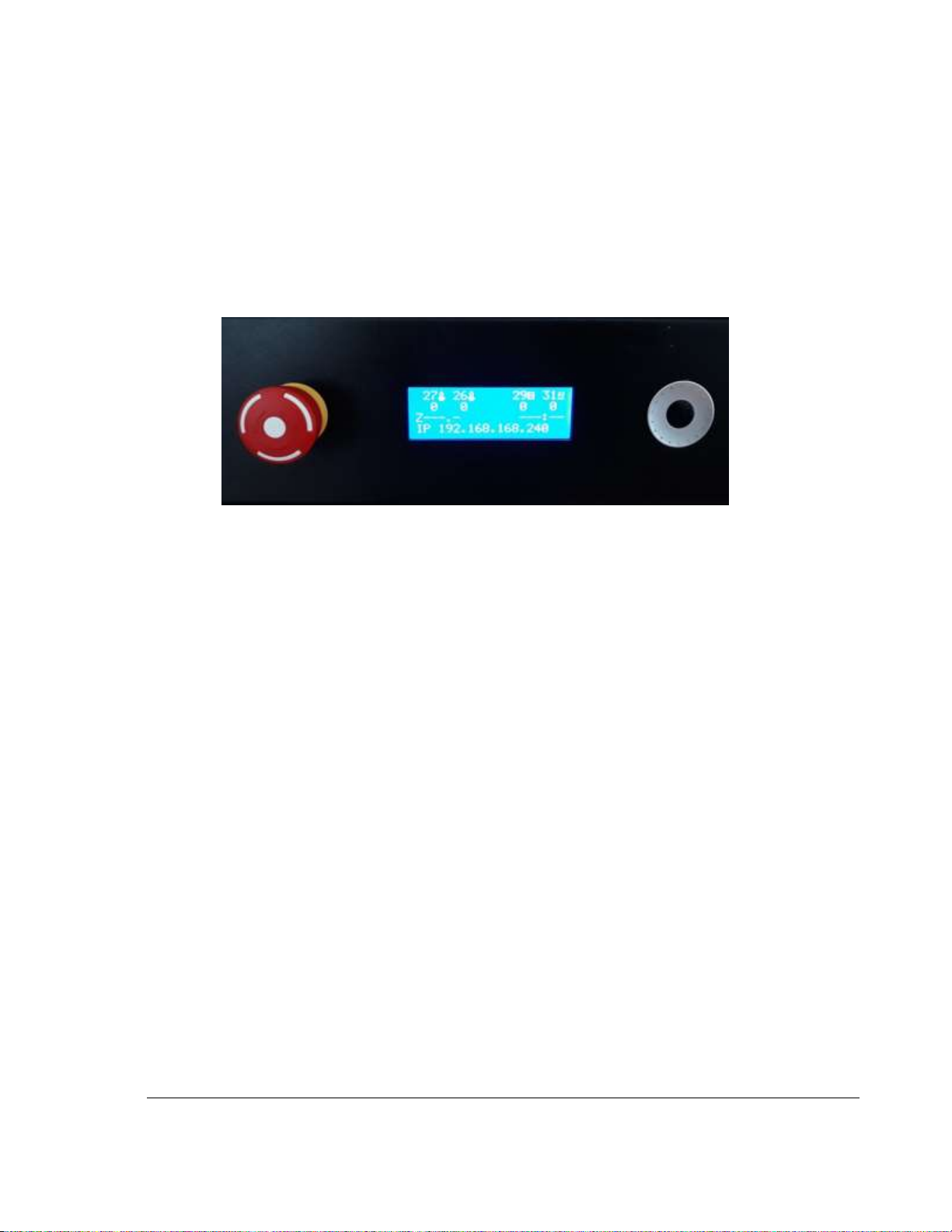
All relevant machine duties can be performed using the printer front panel controls. Front panel controls
consist of a power/E-Stop button, LCD display screen, jog wheel, and black selector button.
• Power E-Stop button – Push in to Emergency STOP printer. Pull with clockwise turn to power ON
the printer.
• LCD Display – Displays printer information, status, control menus.
• Jog Wheel – Rotate in either direction to navigate menus, change values, control printer
• Black Jog Wheel Button – Push to select/initiate
Figure 3.2.1 Printer Front Panel Controls
Printer manual operation and control is performed by navigating through various menus that appear on
the LCD screen using the jog wheel to scroll up/down, increase/decrease a value, and pressing the black
jog wheel button to select/initiate.
Page 12
8
TRAK Machine Tools
Southwestern Industries, Inc.
TRAK 3ntr 3D Printers – Printer & MMS Operation Quick Start Guide
4 Check & Fill Coolant Level
The 3ntr printer is shipped with the coolant reservoir filled; however, check the coolant level before
performing any calibration or test prints.
CAUTION – Printing with insufficient coolant will result in bad prints and in some cases may result in
nozzle and/or extruder damage. Check and replace coolant on a weekly basis.
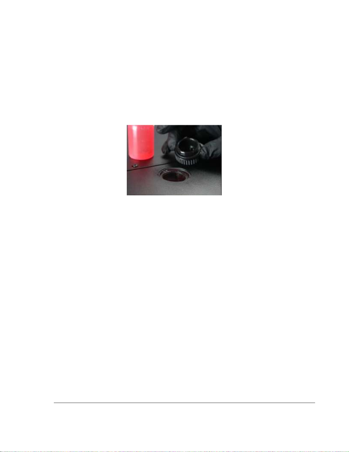
1) Locate the coolant filler cap on the top of the 3ntr printer.
2) Unscrew and inspect the coolant level. If lower ¼” below cap thread fill using the extra coolant
(RED color) supplied with the printer. Use only factory approved coolant. Do not dilute.
Figure 4.1 Proper Coolant Fill Level – ¼ Inch Below Cap Thread
Page 13
9
TRAK Machine Tools
Southwestern Industries, Inc.
TRAK 3ntr 3D Printers – Printer & MMS Operation Quick Start Guide
5 Power on the Printer and MMS Unit (If applicable)
If an MMS unit is used with the 3ntr printer, then the MMS unit must be powered ON before the printer.
5.1 Power on the MMS Unit (If applicable)
Turn ON the MMS unit power switch.
NOTE – The MMS power switch should not be used to shut down the server. Turn OFF the MMS Server
using the “sudo shutdown now” and turn OFF the Printer using the Printer’s power rocker switch or
emergency stop button before turning OFF the MMS unit or disconnecting MMS power. The MMS touch
screen is powered by the MMS server.
5.2 Power on the Printer
1) Press the printer red power switch IN
2) Verify the printer is plugged in. If applicable, verify the MMS unit is plugged in and powered ON.
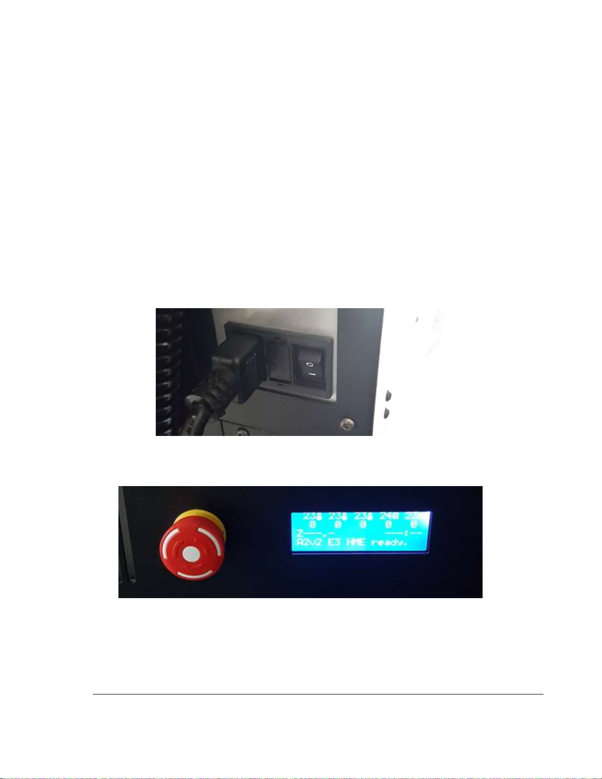
Check the printer back panel power switch (next to the plug) is turned ON as shown.
Figure 5.2.1 Printer power plug and switch
3) Pull the printer red front panel power switch OUT, with a turn clockwise to turn power on the
printer. You should see the LCD panel light up blue and display printer information.
Figure 5.2.2 LCD Display with Power ON
4) If there is movement within the printer, immediately press the red printer front panel power
switch IN to power OFF the printer, then wait 5-10 seconds, then pull and twist clockwise to
power the printer ON again.
5) Your printer is powered ON and ready.
Page 14
10
TRAK Machine Tools
Southwestern Industries, Inc.
TRAK 3ntr 3D Printers – Printer & MMS Operation Quick Start Guide
6 Manual Printer Operation via Front Panel Controls
In this section, you will learn more about using the front panel controls and operate the printer manually,
performing some common printer preparatory functions.
CAUTION – Manual operation of the printer can result in rapid movements of printer bed and extruders.
Do not reach inside the printer while printing or while operating the printer manually. Close all access
doors prior to printing.
6.1 LCD Display and Control Menus Overview
In this section, you will learn about controlling the printer and understand printer status during printing
that is communicated via the LCD display.
6.1.1 LCD Display – Idle Machine Menu
When the machine is not printing, clicking the black jog wheel button will display the Idle machine menu.
Scroll the jog wheel to the desired selection, then press the black button to go to the indicated menu.
Figure 6.1.1 Printer LCD Display Idle Machine Menu
6.1.2 LCD Display – Information Screen
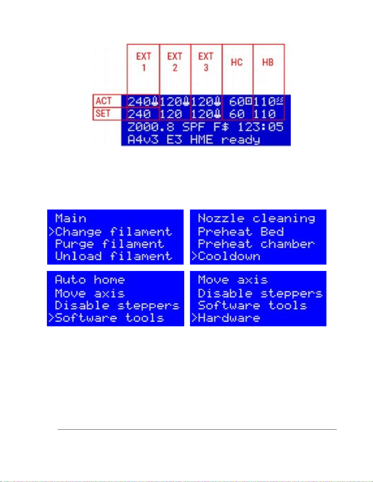
During printing or when executing some automated functions, the LCD will display the information screen
to relay information to the operator regarding printer status. The figure below is the information display
that is shown during printing.
• The first row displays ACTUAL (measured) temperatures for Extruders #1, #2, #3, Heated
Chamber, and Heated Bed.
• The second row displays the TARGET (set point) temperatures for Extruders #1, #2, #3, Heated
Chamber, and Heated Bed.
• The third row displays (from left to right) the current Z level of the printing plate (Z quote –
distance between nozzle and plate), SPFU presence (if installed), filament sensor enabled (F),
filament sensor triggered ($), and elapsed print time of current print.
• The fourth row is the status line – shows various messages
Page 15
11
TRAK Machine Tools
Southwestern Industries, Inc.
TRAK 3ntr 3D Printers – Printer & MMS Operation Quick Start Guide
Figure 6.1.2 Printer LCD Display Information Screen Detail
6.1.3 LCD Display – Prepare Menu
Most common functions necessary for printer manual control, preparation, calibration, filament change,
and printing are available from the Prepare Menu. Some of the selections within the Prepare menu
include automated functions.
Figure 6.1.3 Printer LCD Display: Prepare Menu Selections
6.2 Operate the Printer Manually with LCD/Front Panel Controls
6.2.1 Move Axis Function
The Move Z axis function allows the printer bed to be moved up or down manually in fixed increments.
The Move X,Y axis functions translate the extruders over the printer bed manually in fixed increments.
CAUTION – Only initiate the Move axis function when there is enough clearance between the printer
and anything (such as printed parts) on the printer surface plate. Impact of the extruders, internal
printer components, and anything on the printer surface plate can result in loss or printer damage.
Page 16
12
TRAK Machine Tools
Southwestern Industries, Inc.
TRAK 3ntr 3D Printers – Printer & MMS Operation Quick Start Guide
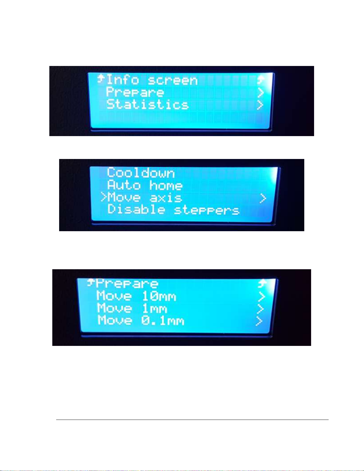
1) Press the black button once to enter the main printer menu (from the information screen)
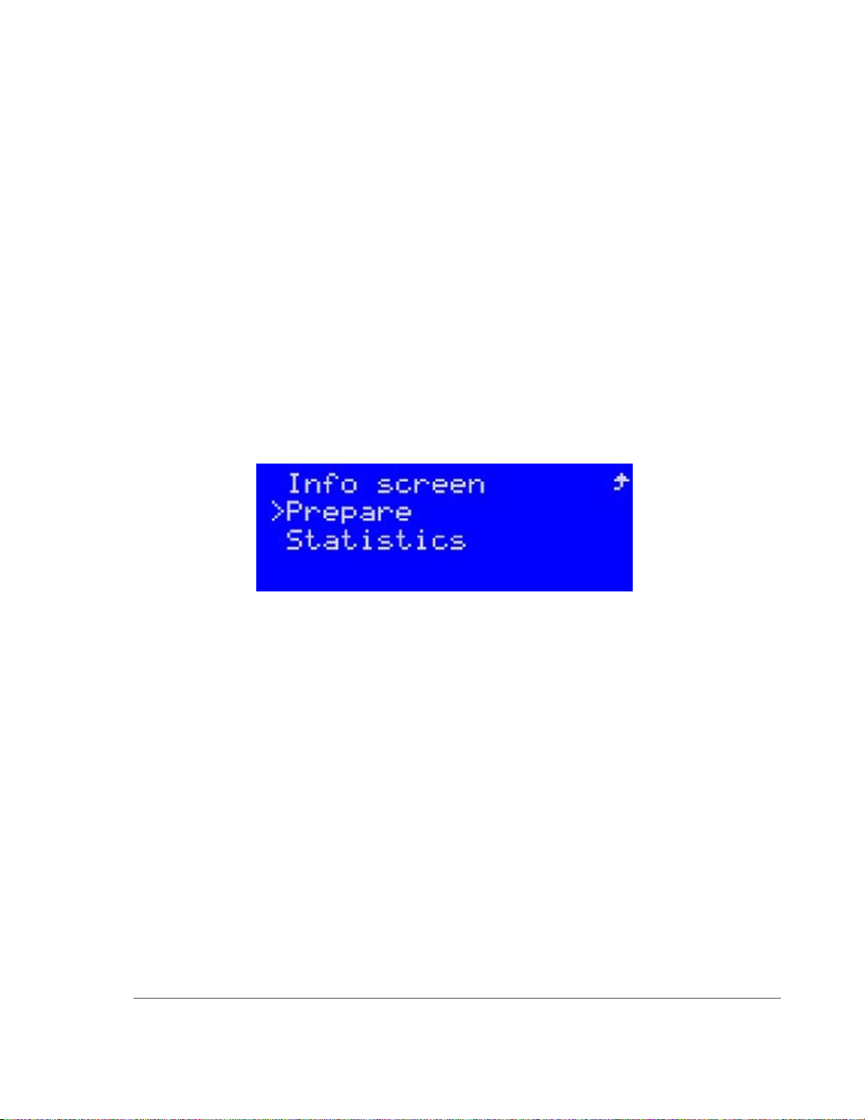
2) Turn the jog wheel until the selector arrow points to Prepare. Press the black button to select.
Figure 6.2.1 LCD Displaying Main Menu
3) Turn the jog wheel until the selector arrow points to Move axis. Press the black button to select.
Figure 6.2.2 Selecting Move Axis from Prepare Menu
4) At this time, you must decide the distance to move. Turn the jog wheel till the arrow points to
either 10 mm, 1mm, or 0.1 mm and press the black button to select the indicated movement
distance. In this example we will select to move 10 mm per jog wheel click/index.
Figure 6.2.3 Selecting Step Size from Move Axis Menu
Page 17
13
TRAK Machine Tools
Southwestern Industries, Inc.
TRAK 3ntr 3D Printers – Printer & MMS Operation Quick Start Guide
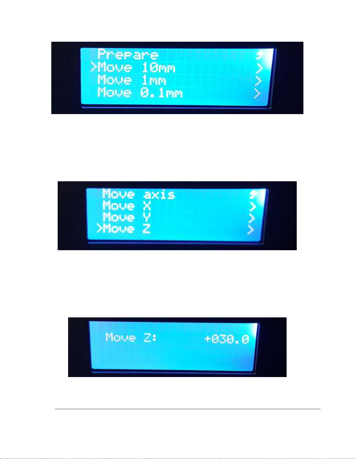
Figure 6.2.4 Selecting Move 10 mm Step
5) Next you must select which axis to move. For this example, we will move the Z axis. Turn the
jog until the selector arrow points to Move Z. Press the black button to select.
CAUTION – After selecting Move X,Y, or Z, turning the jog wheel (each click/index) moves the
selected axis (X, Y, or Z) the selected movement amount (10mm, 1mm, or 0.1 mm). Each move
of the jog wheel buffers a movement and can stack up for an unexpected large movement. Until
familiar with the machine response, it’s best to jog the wheel a little, then observe the movement
completion, the jog the wheel again until reaching your target position.
Figure 6.2.5 Selecting to Move Z Axis on LCD Display
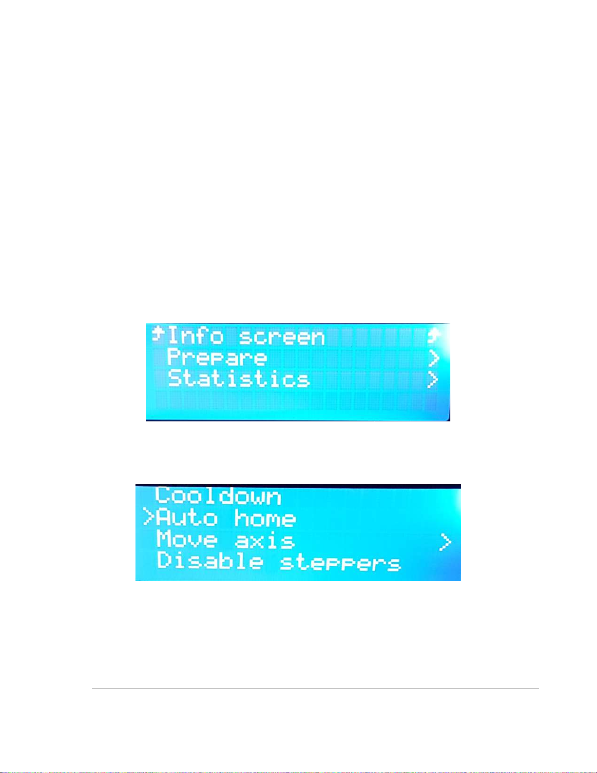
6) At this point, jogging the wheel will move the selected axis. Turning the jog wheel clockwise
moves in the positive direction, turning the jog wheel counter-clockwise moves the axis in the
negative direction. Start by jogging the wheel a click or two and observing the movement.
Depending on the selected movement distance, several clicks or even several full turns may be
required to move the axis a desired direction. Any movement overshoot can be corrected by
turning the other way. The total movement amount (from starting position) is indicated on the
LCD.
Figure 6.2.6 LCD Display Showing Move Axis result
Page 18
14
TRAK Machine Tools
Southwestern Industries, Inc.
TRAK 3ntr 3D Printers – Printer & MMS Operation Quick Start Guide
7) When finished, press the black button to exit live axis movement and restore menu navigation
function to the jog wheel.
8) Turn the jog wheel counterclockwise until the selector points to Return up arrow, then press the
black button to exit the axis selection menu. Continue to navigate back to the Prepare Menu or
other desired menus using the jog wheel and black button.
6.2.2 Auto Home Function
The auto home function returns the printer bed and nozzles to the home position. It also uses a sensor
to re-establish the Z position of the top of the printer surface plate. The home Z sensor is mounted on
an armature on the right side of the printer. When auto home is activated, this sensor rotates out over
the print plate, then rotates back once the operation is completed.
CAUTION – Only initiate the auto home function when the printer surface plate is empty and is properly
locked into place with the magnetic mounts. Use of auto home with anything on the printer plate or
without the printer surface plate properly installed can result in bad prints, damage to parts, extruder,
home sensor and armature.
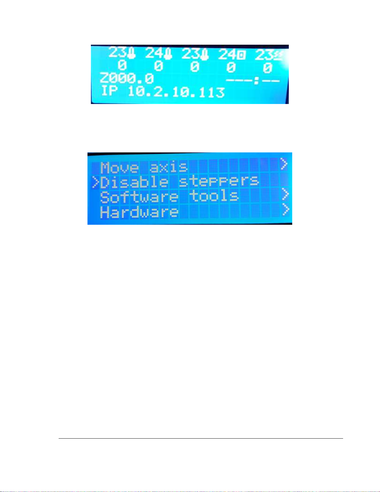
9) Press the black button once to enter the main printer menu (from the information screen)
Figure 6.2.7 LCD Showing Main Menu
10) Turn the jog wheel until the selector arrow points to Prepare. Press the black button to enter the
Prepare menu.
11) Turn the jog wheel until the selector arrow points to Auto home.
Figure 6.2.8 Selecting Auto Home Function
12) Press the black button and watch the printer return the X,Y,Z axis to their original position.
13) Once the Auto home function is complete, you will be returned to the printer information screen.
Page 19
15
TRAK Machine Tools
Southwestern Industries, Inc.
TRAK 3ntr 3D Printers – Printer & MMS Operation Quick Start Guide
Figure 6.2.9 LCD Showing Info Screen
6.2.3 Disable Steppers
Select this command to power off all motors and allow you to move the extruder holder in XY directions
by hand. Note – Z axis cannot be moved by hand – use the LCD move axis function instead.
Figure 6.2.10 Disable Steppers Selection
CAUTION – Only use this function in special circumstances. Fast manual movements may damage the
electronics.
Page 20
16
TRAK Machine Tools
Southwestern Industries, Inc.
TRAK 3ntr 3D Printers – Printer & MMS Operation Quick Start Guide
7 Load Filament/Materials
In this section, you will load filament to the back of the 3ntr printer or into the MMS Unit. The printer is
delivered with 2 spools of ABS/ASA filament suitable for initial set-up calibration and test prints. For
simplicity, use this material.
NOTE – If only unloading filaments/materials from an extruder that will be left empty, you can select the
“Unload filament” function instead, then subsequently perform a “Purge filament” function from the LCD
Prepare Menu.
CAUTION - Only load filament for materials suitable for the 3ntr A2/A4 printers. If necessary, review the
datasheet or materials profiles within KISSlicer to determine acceptable filament types. If you are
changing the polymer type, you must perform a nozzle cleaning procedure before starting a change
filament procedure.
7.1 Load Filament to Back of Printer
This section details the process to load filament onto the back of the printer.
NOTE - If you are using an MMS unit or Humidity Controlled Container (humidity-controlled container)
the process is different. If feeding material directly from a Humidity Controlled Container or equivalent
container, follow the instructions as applicable (new filament spool is not mounted on printer). With an
MMS unit, follow the applicable portions of the instructions below.
1) Check that there is enough clearance (20-30mm) between nozzle and plate before starting. If
not, move printer plate following instructions for “Move Z axis function”
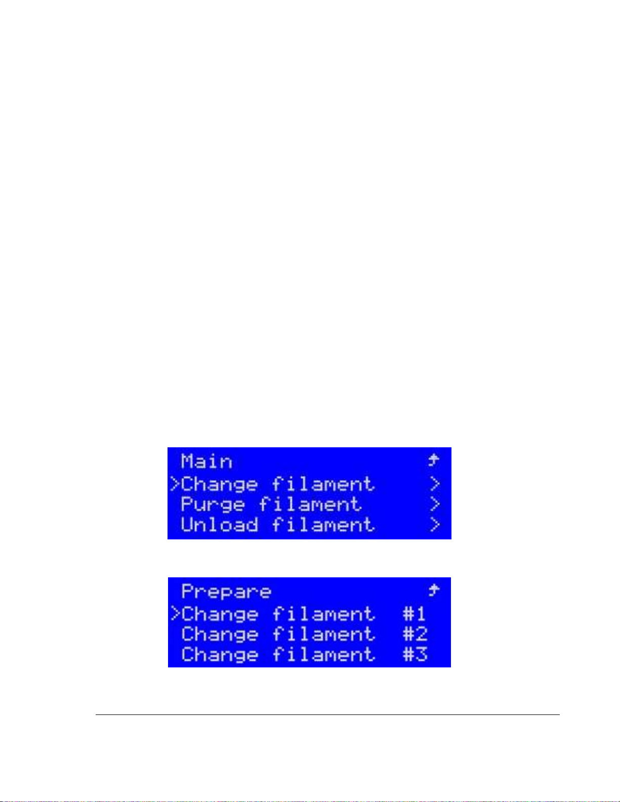
2) Navigate to the Prepare menu. From the Prepare menu select either the “Change filament” (if
filament was previously loaded) or “Load filament” (if empty) function.
Figure 7.1.1 Selecting Function Change Filament
3) Assuming filament has been previously loaded, Select Change Filament “Extruder #1”
Figure 7.1.2 Selecting Extruder # for Change Filament
Page 21
17
TRAK Machine Tools
Southwestern Industries, Inc.
TRAK 3ntr 3D Printers – Printer & MMS Operation Quick Start Guide
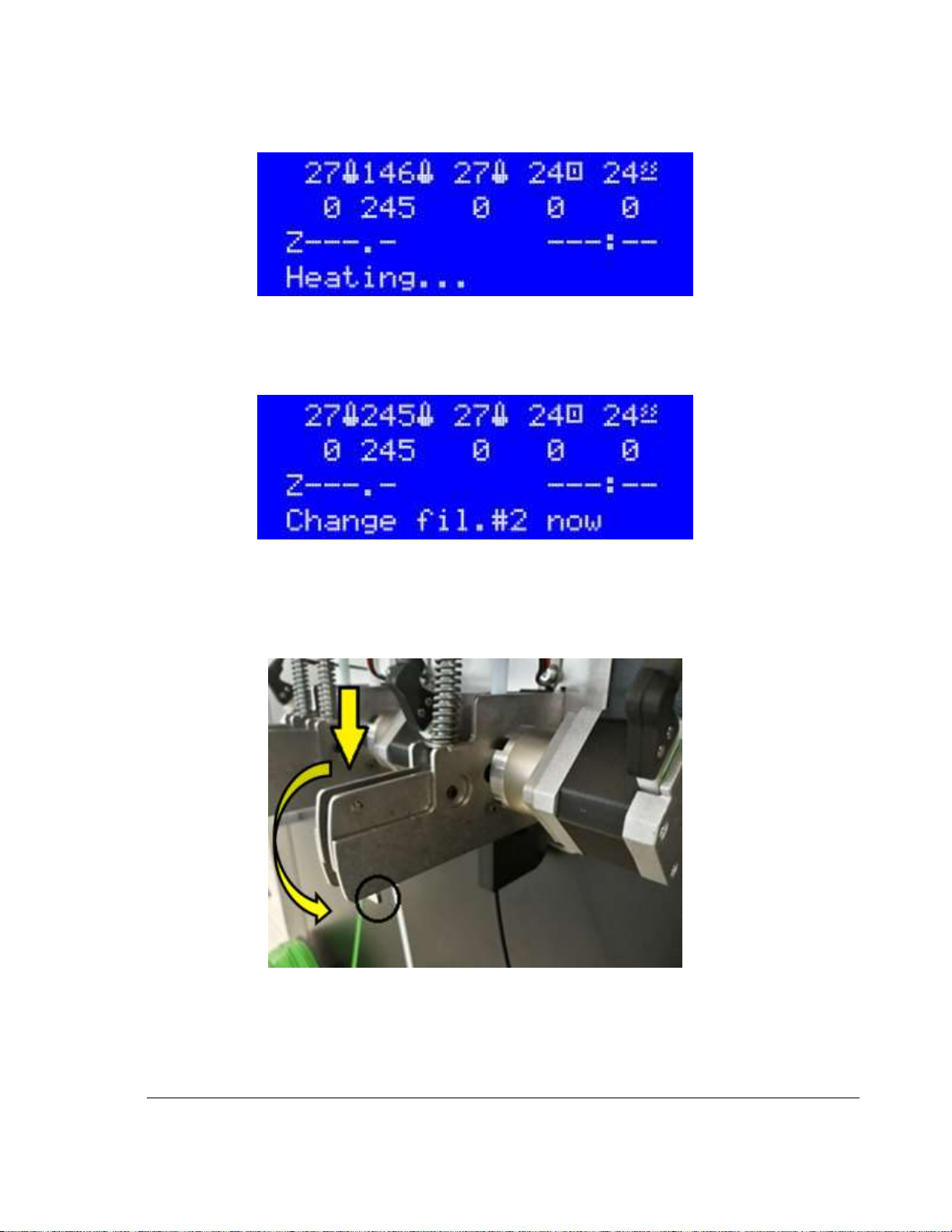
4) The selected extruder will begin heating up and the LCD will display Heating… Observe the
temperature readout for the selected extruder and see it increasing.
Figure 7.1.3 Confirming Selected Nozzle Temperature is Increasing
5) Once the set temperature is reached, the machine will purge some filament. Once this automatic
purging is completed, the display will indicate “Change Filament Now”. At this time, you can now
reach to the back of the cabinet to begin the physical filament change.
Figure 7.1.4 Heating/Purging Completed -Ready for Physical Filament Change
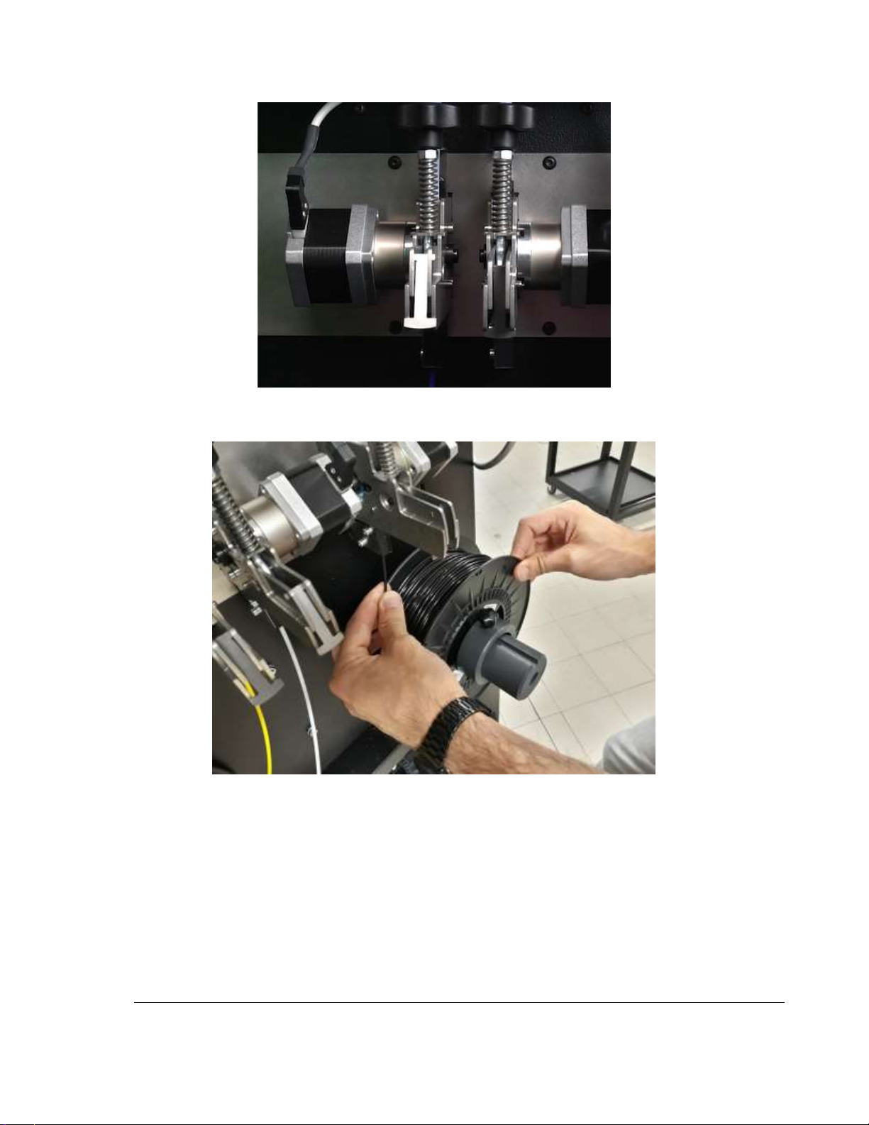
6) Locate the feeder handle on the selected extruder. Grab the feeder handle of the selected
extruder, push it down and secure it into position with the provided lock “lip” This way the feeder
mechanism will be disengaged. Looking at the feeders from the rear of the printer, the rightmost
is the #1 feeder, and leftmost is #3.
Figure 7.1.5 Disengage filament feeder
Page 22
18
TRAK Machine Tools
Southwestern Industries, Inc.
TRAK 3ntr 3D Printers – Printer & MMS Operation Quick Start Guide
Figure 7.1.6 Latched & Unlatched Filament Feeders
7) Pull the filament from the feeder, rewinding the filament onto the spool.
Figure 7.1.7 Pulling old filament out of feeder unit
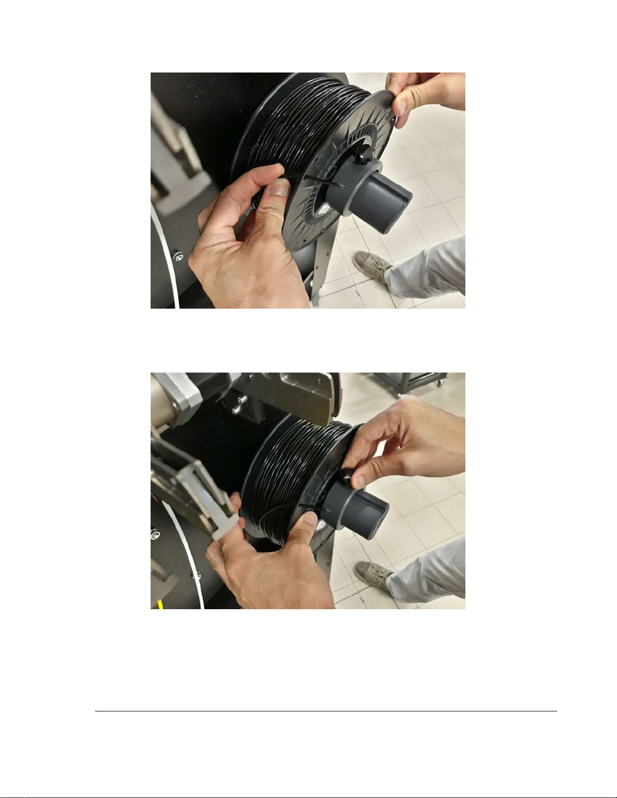
8) Thread the end through the opening on the spool to keep it from de-coiling.
Page 23
19
TRAK Machine Tools
Southwestern Industries, Inc.
TRAK 3ntr 3D Printers – Printer & MMS Operation Quick Start Guide
Figure 7.1.8 Secure filament end to spool
9) Unlock and remove collar from filament spool spindle of selected extruder on back of printer.
Remove filament spool and place in a dry and clean container (with desiccant package) away
from heat and sunlight.
Figure 7.1.9 Securing Filament Spool with collar
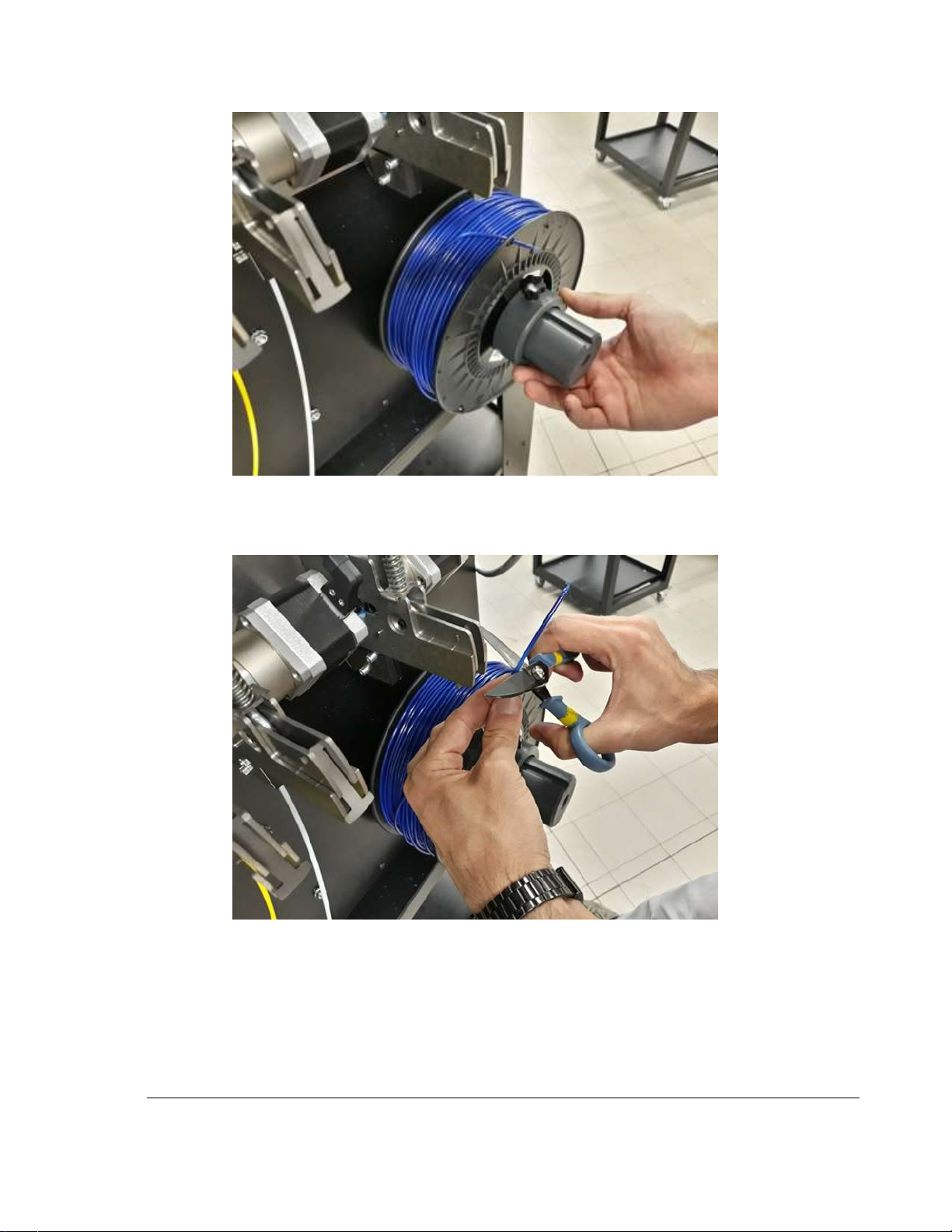
10) Fit the new spool on the holder. Replace the locking collar and secure it to prevent de-coiling.
Page 24
20
TRAK Machine Tools
Southwestern Industries, Inc.
TRAK 3ntr 3D Printers – Printer & MMS Operation Quick Start Guide
Figure 7.1.10 Install and secure a new filament spool
11) Remove the filament end from where secured to the spool. Trim off several mm to remove
bends, dirt, tape, or damage.
Figure 7.1.11 Trim off the end of new filament
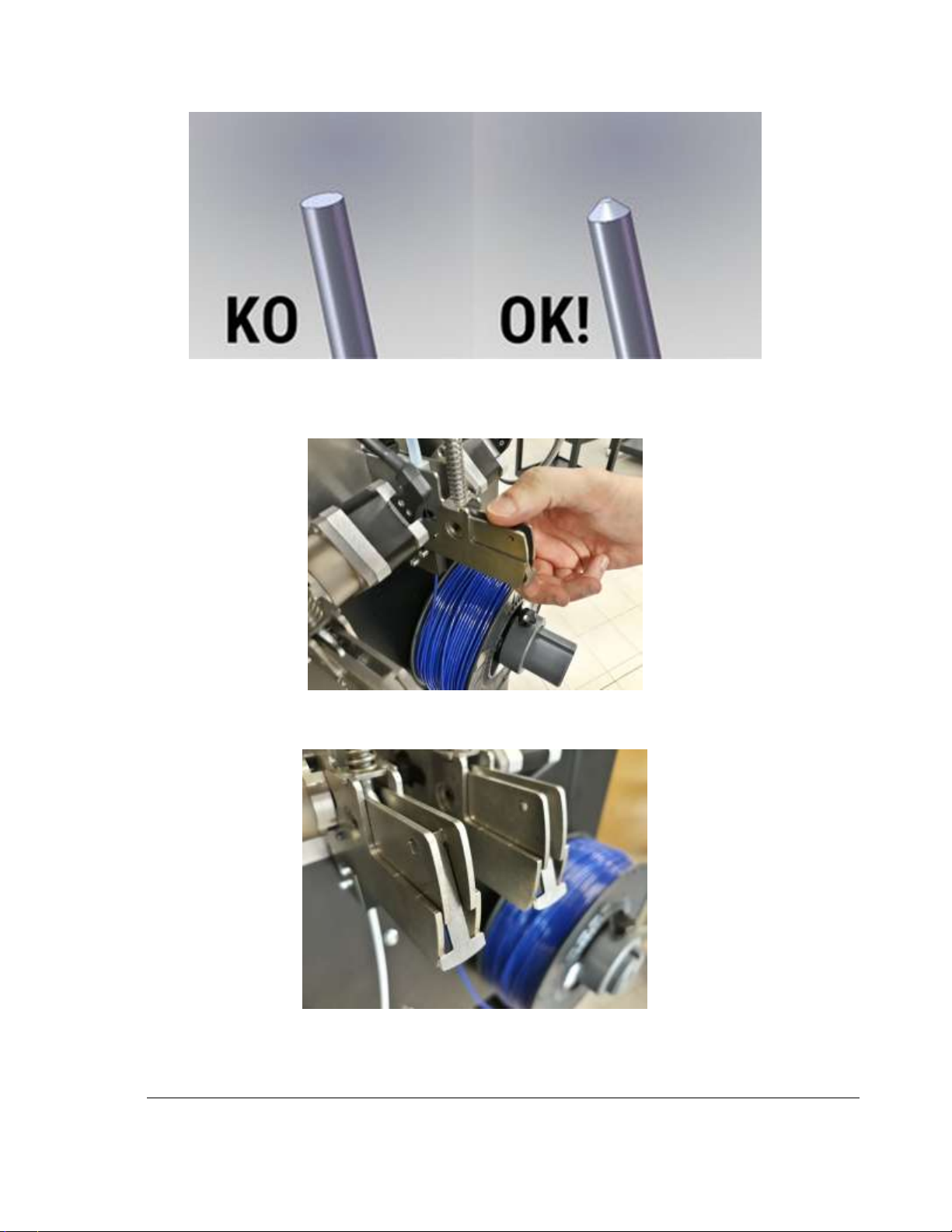
12) Use scissors, knife, or a pencil sharpener to point the filament end for easy feeding to the
extruder.
Page 25
21
TRAK Machine Tools
Southwestern Industries, Inc.
TRAK 3ntr 3D Printers – Printer & MMS Operation Quick Start Guide
Figure 7.1.12 Illustration of correct and incorrect filament tip sharpening
13) Feed the filament into the feeder unit and keep feeding until the end stops at the extruder.
Release the feeder handle. Verify the locking “tab” is disengaged.
Figure 7.1.13 Engage the filament feeder
14) The locking tab is now engaged. The machine will automatically control the filament feed.
Figure 7.1.14 Filament feeder in the engaged position
Page 26
22
TRAK Machine Tools
Southwestern Industries, Inc.
TRAK 3ntr 3D Printers – Printer & MMS Operation Quick Start Guide
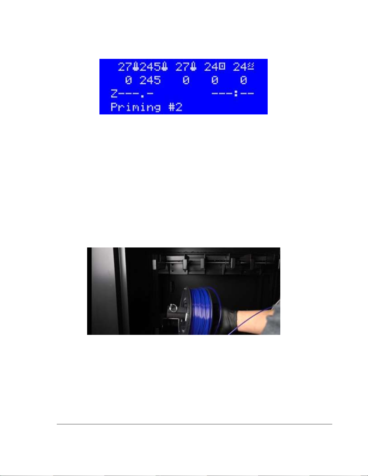
15) Press the button on the jog wheel. The LCD will display “Priming #” as it purges some filament.
Upon completion, the LCD will display “Change #x Complete” to indicate completion.
Figure 7.1.15 LCD Display while new filament is priming (A2 Printer Only)
16) Repeat for remaining desired filament materials/extruders.
17) Clean any residual element remaining. Clean the printing tray area.
18) Machine is now ready!
7.2 Loading Filament/Material into the MMS Unit
Loading Filament/Material to the MMS Unit differs only a little from the process of loading material to the
back of the Printer detailed in the section: Load Filament/Materials. Please follow the instructions from
that section, making the following adjustments for the MMS Unit.
Key differences are highlighted here:
• Filament spools are located within the MMS instead of the back of the printer
• The MMS spool holders (loose pieces/not attached) are threaded through filament spools and
secured with a locking pin.
Figure 7.2.1 Placing Filament Spool & Holder in MMS Unit
• The spool holders rest on support arms (weigh scales) within the MMS
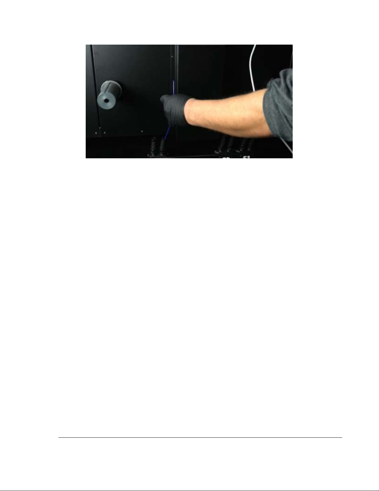
• The filament must be fed through the openings in the MMS and/or the PTFE tubing from MMS to
the filament feeder.
Page 27
23
TRAK Machine Tools
Southwestern Industries, Inc.
TRAK 3ntr 3D Printers – Printer & MMS Operation Quick Start Guide
Figure 7.2.2 Pulling Filament from MMS up to Feeder
• After loading materials into the MMS, make sure they are not tangled, and close the door quickly
to avoid increasing the humidity inside.
• You must access the MMS Server and click the Dash button to add/select materials and set spool
sizes for the actual material loaded in each extruder/storage position.
NOTE - This step is needed to ensure the materials loaded match what is viewable from the print
server.
CAUTION - If you fail to update the MMS Server with the filament spool details after loading,
bad prints may result because of insufficient filament or mistaken filament size/type (does not
match g-code print file).
7.3 Filament Care/Storage
In this section, we will highlight basic 3D print materials care/storage instructions.
NOTE - 3D printing materials are vulnerable to humidity, temperature, and contamination, with some
materials much more sensitive than others. The best way to care for and store 3D print materials is
within the MMS unit. If you are using a Humidity Controlled Container or MMS unit, and the MMS unit is
powered and maintained, no other steps are required. If no MMS is used, or materials are removed from
the MMS after use, please follow these instructions to maintain the quality of subsequent prints.
1) Consult and follow the manufacturer’s recommendations for individual filament type care/storage.
2) Keep filaments within their sealed packaging until immediately before use.
Page 28
24
TRAK Machine Tools
Southwestern Industries, Inc.
TRAK 3ntr 3D Printers – Printer & MMS Operation Quick Start Guide
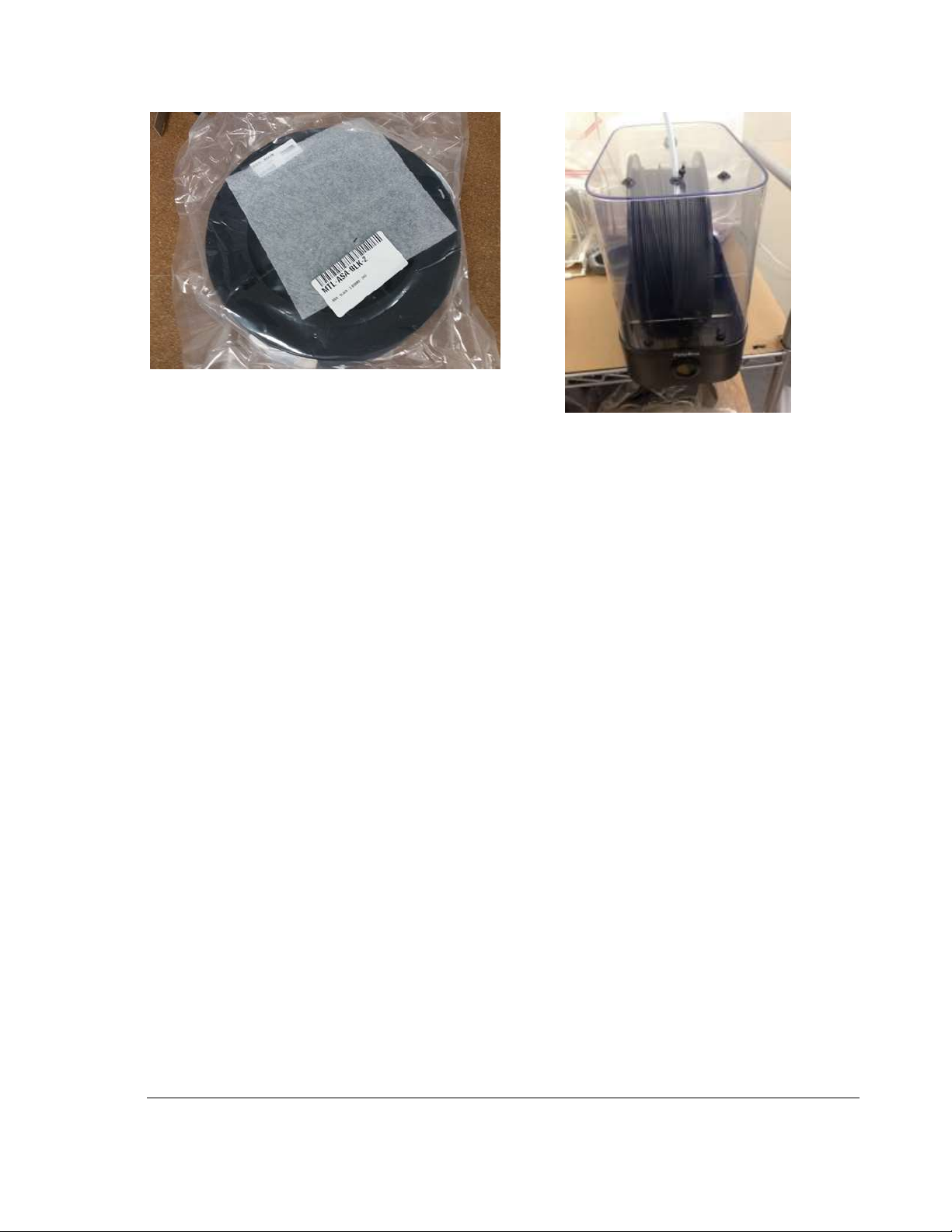
Figure 7.3.1 Factory supplied filament in storage
package
Figure 7.3.2 Humidity Controlled
Storage Container with
Protective Tubing
3) Immediately after use (or removal from MMS unit), return materials to a sealed container (plastic
bag) containing a desiccant package or closed Humidity Controlled Container.
4) After several months of storage (after opening the new package), or if filament has been
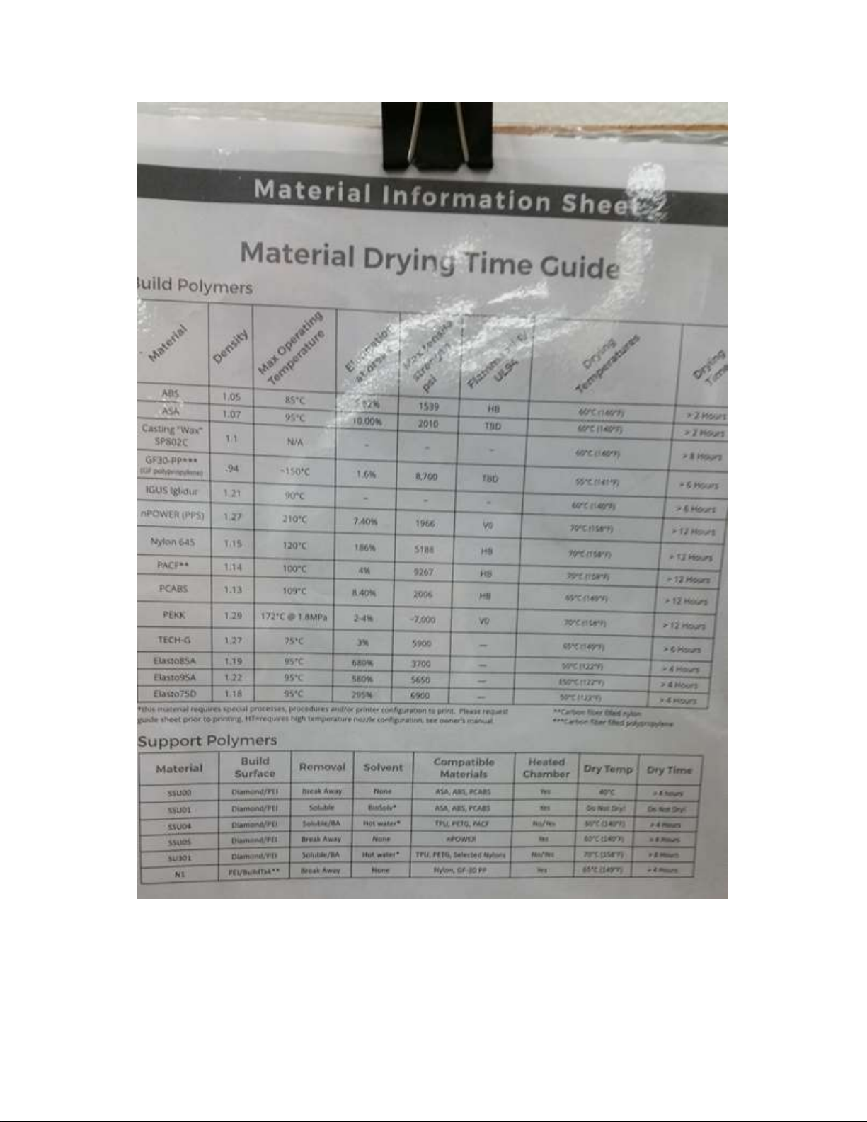
exposed to humidity, use a filament dryer to completely remove humidity before printing.
Page 29
25
TRAK Machine Tools
Southwestern Industries, Inc.
TRAK 3ntr 3D Printers – Printer & MMS Operation Quick Start Guide
Figure 7.3.3 Drying Times Table for Common Print Materials
NOTE - After mounting a new filament, if popping or crackling continues during the purge
operation, remove the filament and dry before printing parts.
Page 30
26
TRAK Machine Tools
Southwestern Industries, Inc.
TRAK 3ntr 3D Printers – Printer & MMS Operation Quick Start Guide
8 Purge Nozzle/Filament
In this section, you will complete a common operation performed BEFORE changing to a different
material and when nozzle flow issues are observed. TRAK 3ntr printers are typically delivered without
any filament installed/remaining in the extruder. Check and if there is filament in the extruder, you must
perform a Purge #1 and Purge #2 operation as described in this section.
NOTE – The Change filament or Load filament functions automatically perform a purge operation after
new materials is loaded using the automatic function. Additional purge cycles (as described in this
section) may be required until the expelled material no longer contains material previously loaded.
CAUTION – Before purging nozzles, check to verify there is adequate clearance between the extruder
and the printer surface plate. Use the Move Z axis function (instructions above) to jog down if necessary.
If desired for the purged material to flow onto the printer surface plate, or to observe the flow, use the
Move X and/or Move Y functions to position extruders over the desired location.
CAUTION – Before purging nozzles, verify the default purging temperature (245° C) is acceptable for
the material in use, otherwise use a custom purging routine/temperature. The default setting is
acceptable for the ABS/ASA materials that ship with the printer.
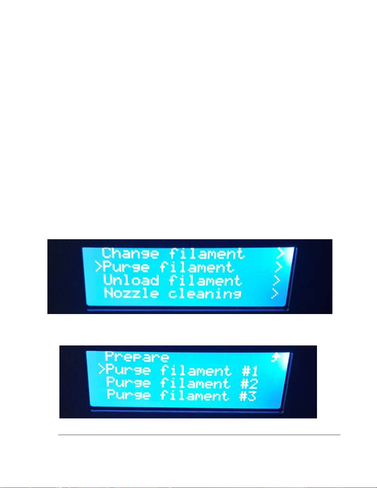
1) Begin by pressing the black button to enter the Main printer menu (from the information display).
Turn the jog wheel until the selector points to the Prepare menu, then press the black button to
select. Scroll down the menu until the selector points to the Purge filament menu and press the
black button to select.
Figure 8.1 Selecting the Purge Function from Prepare Menu
2) Scroll down until the selector points to the desired extruder for purging (Purge Filament #1 in
this example), then press the black button to select.
Figure 8.2 Selecting which Extruder to Purge
Page 31
27
TRAK Machine Tools
Southwestern Industries, Inc.
TRAK 3ntr 3D Printers – Printer & MMS Operation Quick Start Guide
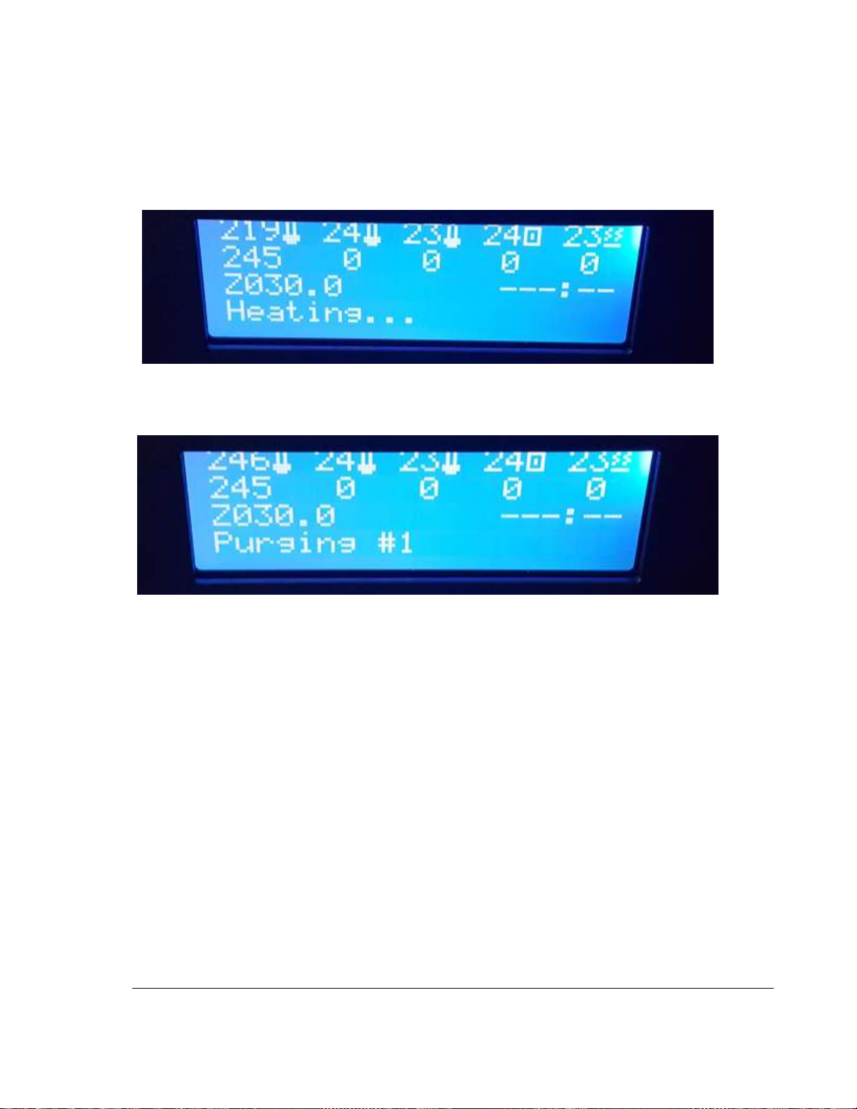
3) The information menu will reappear along with status information. The target temperature is
displayed (245° in this example) along with the status message “Heating….” The actual
temperature for the selected extruder is also displayed and should be increasing. You may hear
some crackles as ambient water vapor boils off and the filament begins moving though the
nozzle.
Figure 8.3 Info Screen While Heating Extruder
4) Next, when the selected extruder reaches the indicated target temperature, purging begins as
indicated by ‘Purging #1” status message.
Figure 8.4 Info Screen While Purging
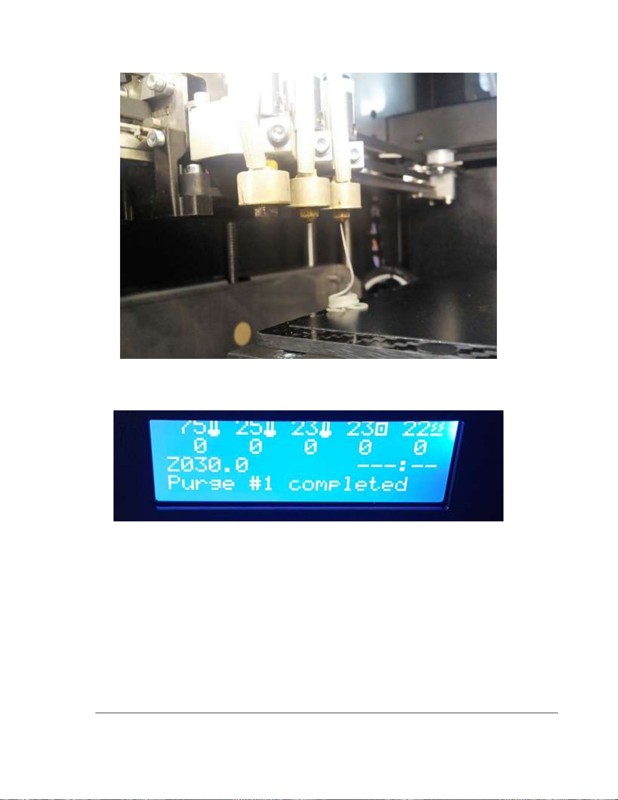
5) Observe the flow of the purged material.
Page 32
28
TRAK Machine Tools
Southwestern Industries, Inc.
TRAK 3ntr 3D Printers – Printer & MMS Operation Quick Start Guide
Figure 8.5 Extruder Purging Filament
6) When the purging operation is complete, the printer stops automatically and displays “Purging
completed”
Figure 8.6 Info Screen Upon Purge Completion
7) Next, the printer returns to the info screen.
8) Repeat process for nozzles #2 and #3, if/as required.
9) Clean the purged filament and any debris from the printer. You can safely remove purged
materials with either small tweezers or your hands after a brief cooling period. Standard ABS/ASA
material that ships with the printer cools and solidifies rapidly.
10) Purging Complete.
Page 33
29
TRAK Machine Tools
Southwestern Industries, Inc.
TRAK 3ntr 3D Printers – Printer & MMS Operation Quick Start Guide
9 Clean Nozzles
This section details all the steps to clean extruder nozzles. Nozzle cleaning is commonly performed when
changing filaments, if undesirable flow conditions are present, or during routine printer maintenance, setup, and/or installation activities. When required, each nozzle must be individually cleaned.
NOTE - The nozzle cleaning procedure must ALWAYS be performed BEFORE changing to a new polymer
type filament. A nozzle cleaning procedure should always be performed any time there are unacceptable
nozzle flow conditions that cannot be cleared with several purge cycles. Nozzle cleaning may also be
required during common maintenance and print job set-up procedures such as a nozzle change, installing
and SPFU, reconfiguring extruders, and more.
9.1 Clean Nozzle Procedure Overview:
There are three steps to cleaning nozzles;
1) Remove existing filament(s) using the change filament function
2) Feed cleaning filament (nylon) to the extruder(s)
3) Clean nozzle(s) using the front panel control Clean Nozzle function
CAUTION - Only load factory recommended (nylon or equivalent) filament for cleaning procedures.
NOTE - Before using the Clean Nozzle function from the front panel, you must use the Change/Load
Cleaning Filament procedure to remove build/support filament and feed the nylon cleaning filament to the
extruders to be cleaned.
9.2 Unload Filament Using Change Filament Function
In this section, you will change filament removing existing spools before installing the cleaning filament
(instead of a new build/support material filament spool). It should always be performed before a nozzle
cleaning procedure.
NOTE - If you are using an MMS unit or PolyBox (humidity-controlled container) the process is different.
If feeding material directly from a PolyBox or equivalent container, follow the instructions as applicable
1) Check that there is enough clearance (20-30mm) between nozzle and plate before starting. If
not, move printer plate following instructions for “Move Z axis function”
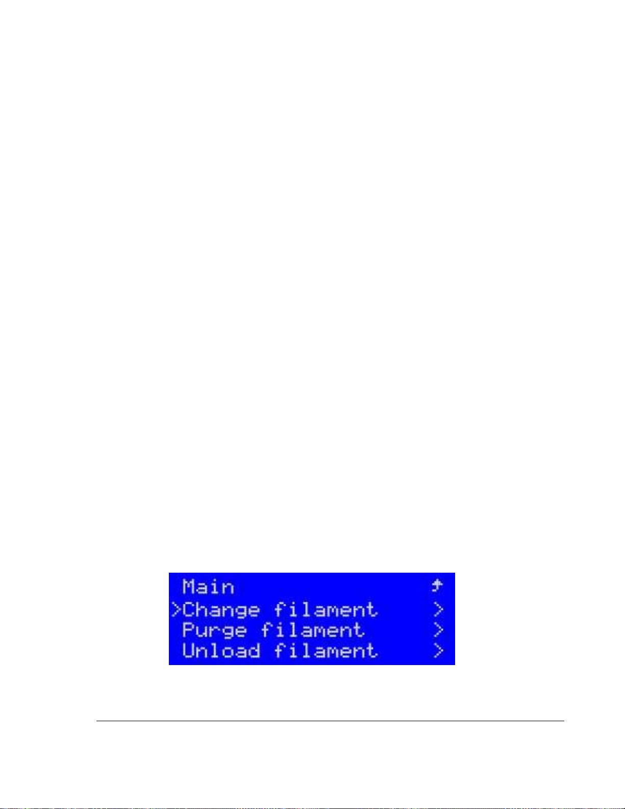
2) Navigate to the Prepare menu. From the Prepare menu select “Change filament”
Figure 9.2.1 Selecting Change Filament from Prepare Menu
Page 34
30
TRAK Machine Tools
Southwestern Industries, Inc.
TRAK 3ntr 3D Printers – Printer & MMS Operation Quick Start Guide
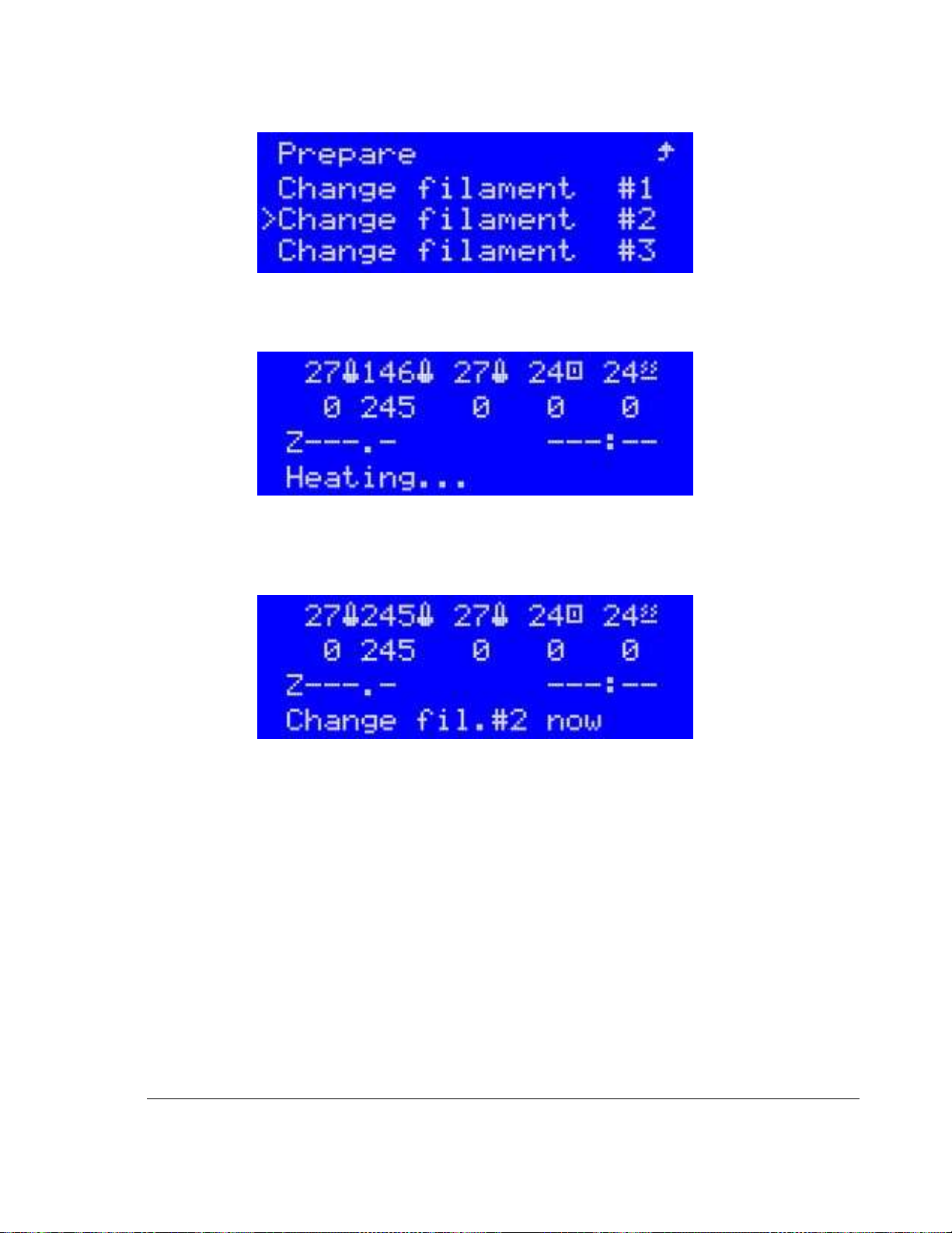
3) Assuming filament has been previously loaded, Select Change Filament “Extruder #1”
Figure 9.2.2 Selecting Extruder for Change Filament
4) The selected extruder will begin heating up and the LCD will display Heating… Observe the
temperature readout for the selected extruder and see it increasing.
Figure 9.2.3 Info Display During Change Filament
5) Once the set temperature is reached, the machine will purge some filament. Once this automatic
purging is completed, the display will indicate “Unload Filament Now”. At this time, you can now
reach to the back of the cabinet to unload the filament.
Figure 9.2.4 Printer Readiness Signal to Change Filament Spool
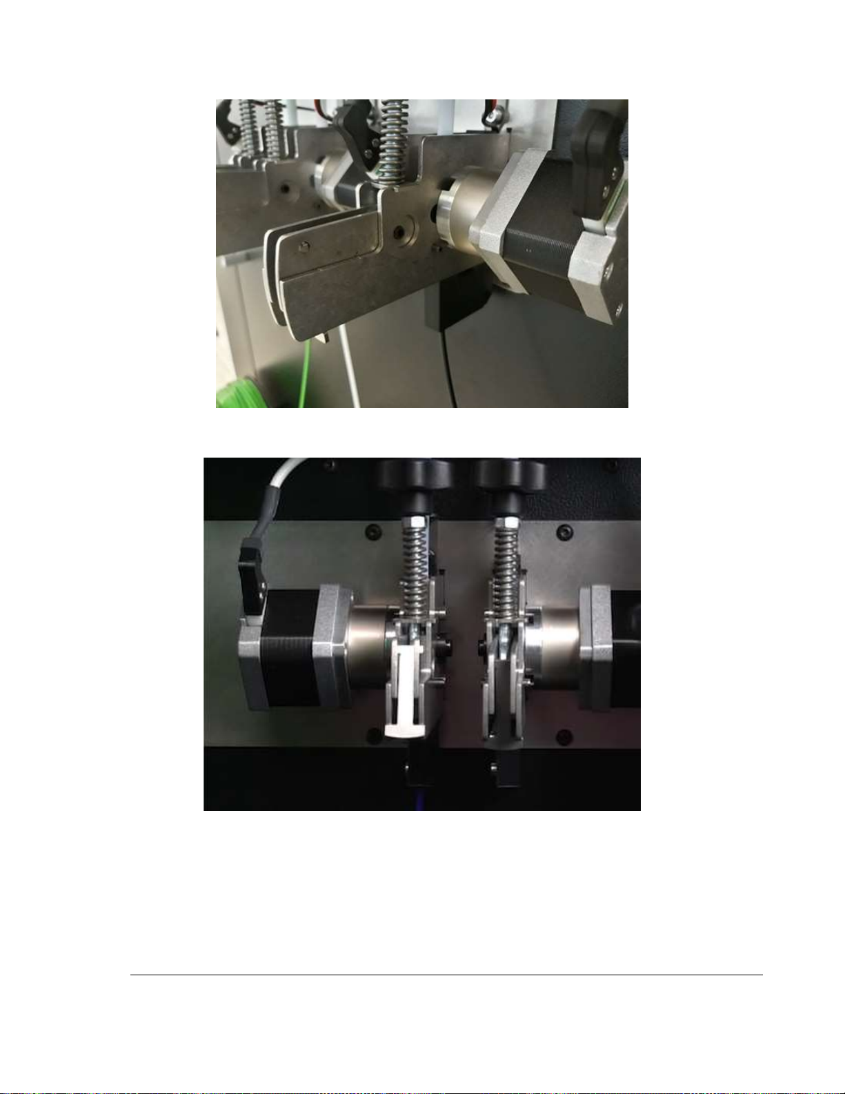
6) Locate the feeder handle on the selected extruder. Grab the feeder handle of the selected
extruder, push it down and secure it into position with the provided lock “lip” This way the feeder
mechanism will be disengaged. Looking at the feeders from the rear of the printer, the rightmost
is the #1 feeder, and leftmost is #3.
Page 35
31
TRAK Machine Tools
Southwestern Industries, Inc.
TRAK 3ntr 3D Printers – Printer & MMS Operation Quick Start Guide
Figure 9.2.5 Disengage filament feeder
Figure 9.2.6 Latched & Unlatched Filament Feeders
Page 36
32
TRAK Machine Tools
Southwestern Industries, Inc.
TRAK 3ntr 3D Printers – Printer & MMS Operation Quick Start Guide
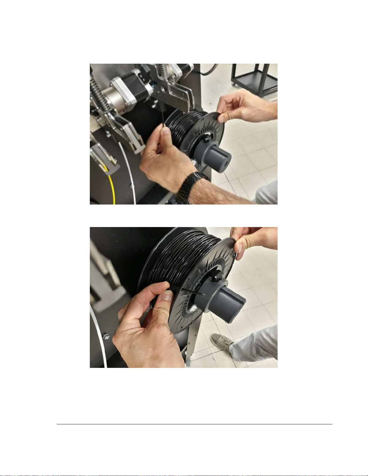
7) Pull the filament from the feeder, rewinding the filament onto the spool.
Figure 9.2.7 Pulling old filament out of feeder unit
8) Thread the end through the opening on the spool to keep it from de-coiling.
Figure 9.2.8 Secure filament end to spool
9) Unlock and remove collar from filament spool spindle of selected extruder on back of printer.
Remove filament spool and place in a dry and clean container (with desiccant package) away
from heat and sunlight.
Page 37
33
TRAK Machine Tools
Southwestern Industries, Inc.
TRAK 3ntr 3D Printers – Printer & MMS Operation Quick Start Guide
9.3 Load Cleaning Filament
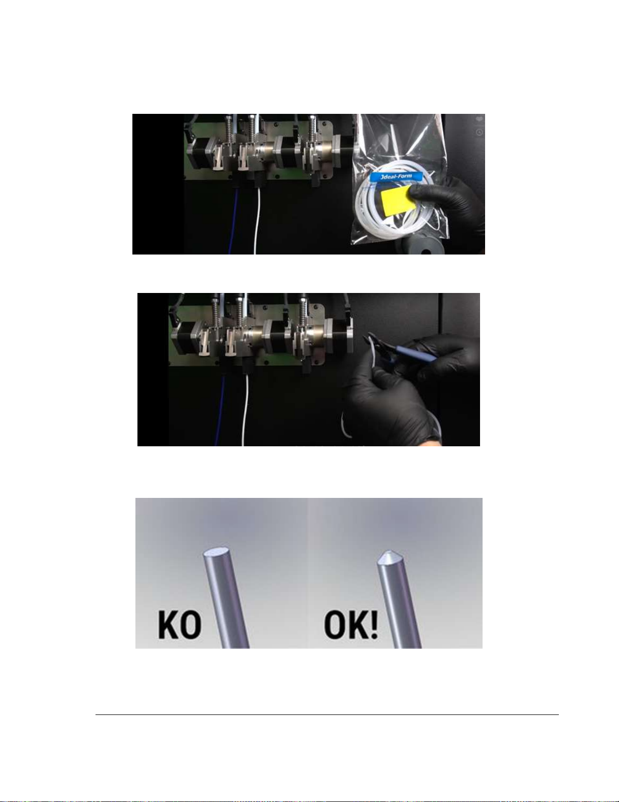
1) Obtain the cleaning filament (Hollow nylon filament specially for nozzle cleaning).
Figure 9.3.1 Nozzle Cleaning Filament (Nylon)
2) Trim off several mm to remove bends, dirt, tape, or damage. Straighten as needed.
Figure 9.3.2 Trim off the end of new filament
3) Use scissors, knife, or a pencil sharpener to point the filament end for easy feeding to the
extruder.
Figure 9.3.3 Illustration of correct and incorrect filament tip sharpening
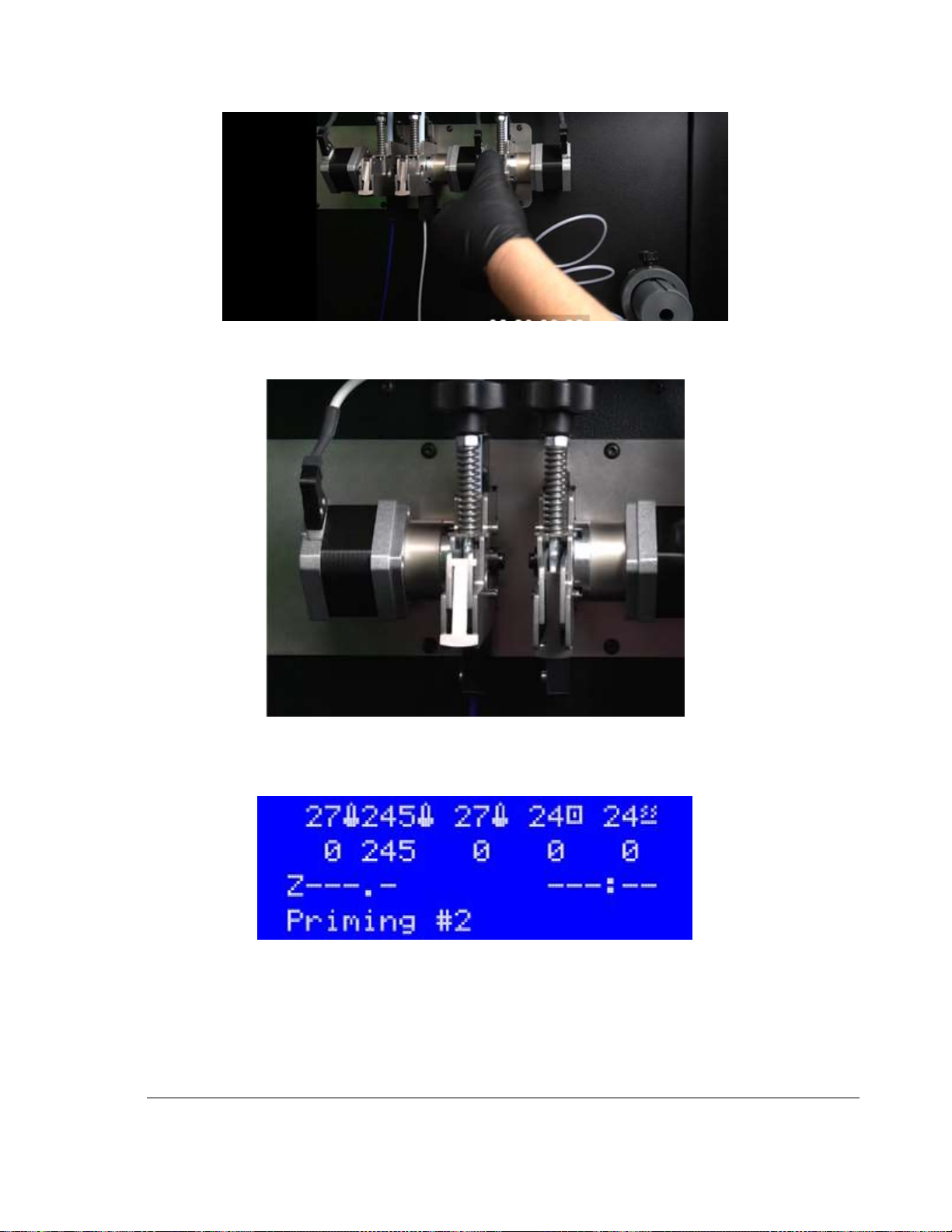
4) Feed the filament into the feeder unit and keep feeding until the end stops at the extruder.
Release the feeder handle. Verify the locking “lip” is disengaged.
Page 38
34
TRAK Machine Tools
Southwestern Industries, Inc.
TRAK 3ntr 3D Printers – Printer & MMS Operation Quick Start Guide
Figure 9.3.4 Engage the filament feeder
5) The locking lip is now engaged. The machine will automatically control the filament feed.
Figure 9.3.5 Latched and Unlatched Filament Feeders
6) Press the button on the jog wheel. The LCD will display “Priming #X” as it purges some filament.
Upon completion, the LCD will display “Change #x Complete” to indicate completion.
Figure 9.3.6 LCD Display while new filament is priming
7) Repeat filament change/load cleaning filament procedure for extruder #2 (as necessary)
8) Repeat filament change/load cleaning filament procedure for extruder #3 (as necessary)
9) Procedure complete!
Page 39
35
TRAK Machine Tools
Southwestern Industries, Inc.
TRAK 3ntr 3D Printers – Printer & MMS Operation Quick Start Guide
9.4 Nozzle Cleaning (Automated Function)
This section details the nozzle cleaning procedure. The nozzle cleaning procedure must ALWAYS be
performed BEFORE changing to a new polymer type filament. A nozzle cleaning procedure should always
be performed any time there are unacceptable nozzle flow conditions that cannot be cleared with several
purge cycles.
NOTE - Before using the Clean Nozzle function from the front panel, you must use the Change Filament
procedure to remove build/support filament and feed the nylon cleaning filament to the extruders to be
cleaned.
1) Use CHANGE FILAMENT/Load Cleaning Filament procedure (see appropriate guide section for
instructions) to remove filament in use and to load cleaner filament to the machine.
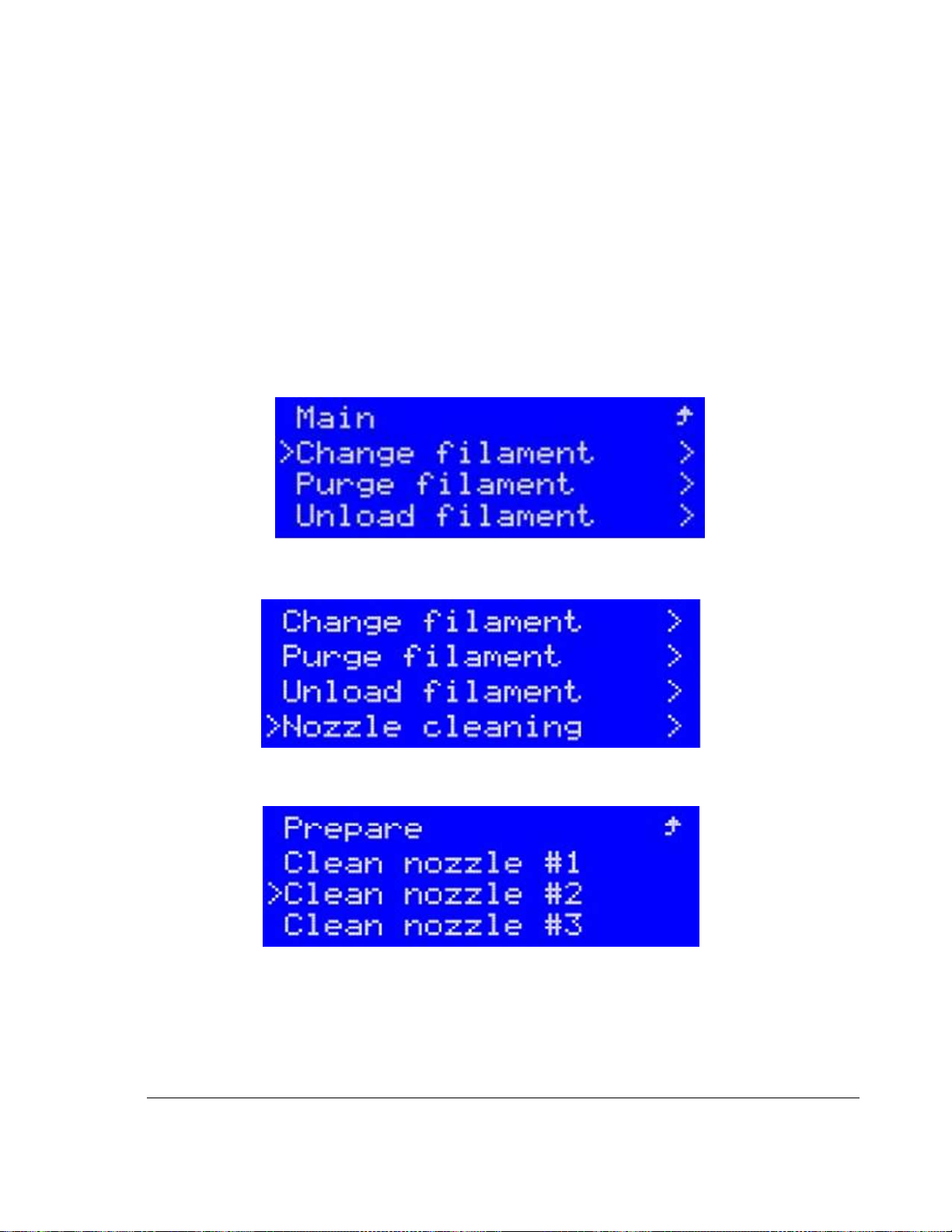
Figure 9.4.1 Change Filament Function
2) Select the nozzle cleaning function from the printer control panel Prepare Menu
Figure 9.4.2 Prepare Menu: Nozzle Cleaning Selected
3) Choose the nozzle to be cleaned (Nozzle #2 in this example)
Figure 9.4.3 Select Extruder for Cleaning
4) After verifying the nylon cleaning filament is properly loaded into the extruder, press the black
jog wheel button to start the automatic cleaning procedure.
Page 40
36
TRAK Machine Tools
Southwestern Industries, Inc.
TRAK 3ntr 3D Printers – Printer & MMS Operation Quick Start Guide
Figure 9.4.4 Printer indication – Ready to Clean
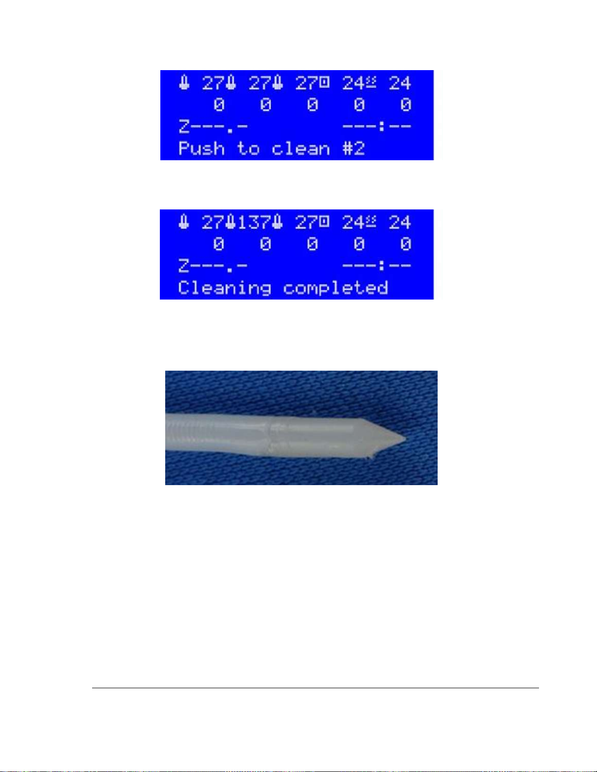
5) The printer will now heat the chosen extruder, clean the nozzle, then cool it down to a preset
value and pulls out the filament (from the heated nozzle) for you to check it.
Figure 9.4.5 LCD Indicating Cleaning Complete
6) Inspect the cleaning filament tip after the cleaning cycle.
7) If the filament tip appears with the proper shape and no traces of color, then the cleaning
process can be concluded, if not, additional steps are required (below)
Figure 9.4.6 Ideal Cleaning Filament Tip (after cleaning)
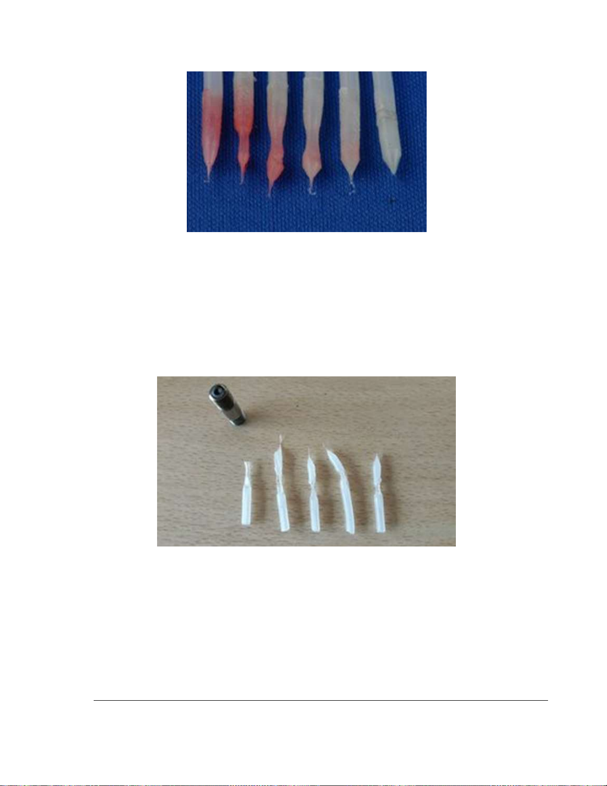
8) If the filament tip after cleaning has any traces of color on it (as below), repeat the cleaning
process for additional cycles, until no traces of color remain.
Page 41
37
TRAK Machine Tools
Southwestern Industries, Inc.
TRAK 3ntr 3D Printers – Printer & MMS Operation Quick Start Guide
Figure 9.4.7 Cleaning Filament Tip Color after multiple Cleaning Cycles
9) If the shape of the extruded cleaning filament tip after the cleaning cycle is not ideal (as
pictured above), repeat the cleaning cycle a couple times.
10) If an ideal cleaning filament tip is not obtained after a couple cycles (bad tips shown below),
perform the following extruder troubleshooting steps:
a. Check/Fill coolant liquid level
b. Verify coolant fluid flow to extruder
c. Check extruder thermal gain setting (correct if necessary)
d. Perform a Feeder roller cleaning procedure
e. Nozzle change (may be required)
Figure 9.4.8 Bad Tips after Filament Cleaning: Requires Troubleshooting
11) Repeat entire cleaning process for other extruders (as required/needed)
12) Nozzle cleaning function complete!
Page 42
38
TRAK Machine Tools
Southwestern Industries, Inc.
TRAK 3ntr 3D Printers – Printer & MMS Operation Quick Start Guide
10 MMS Unit Operation
This section provides information regarding the use and operation of the MMS Unit after initial set-up.
10.1 MMS Overview
The TRAK Plural Material Management System v2 is designed to properly store a range of materials ready
for feeding or fed to the printer from a humidity-controlled environment which insures optimum print
quality and part performance. With the server installed and connected to your network, both the
browser-based remote dashboard and the touchscreen on the MMS will display live material quantity
readouts in meters or grams for each of 6 spools of material.
Please review the information in this guide to take best advantage of the MMS and its functionality. See
“Controlling the RH in the Cabinet” later in this document for details on maximizing the performance of
the cabinet and desiccant.
10.2 Power ON the MMS Unit
NOTE: The MMS power switch should not be used to shut down the server. Before turning off MMS
power, shut down the MMS server (“sudo shutdown now”) and power off the printer using the printer’s
power switch or emergency stop button. (the MMS touch screen is powered by the MMS server.
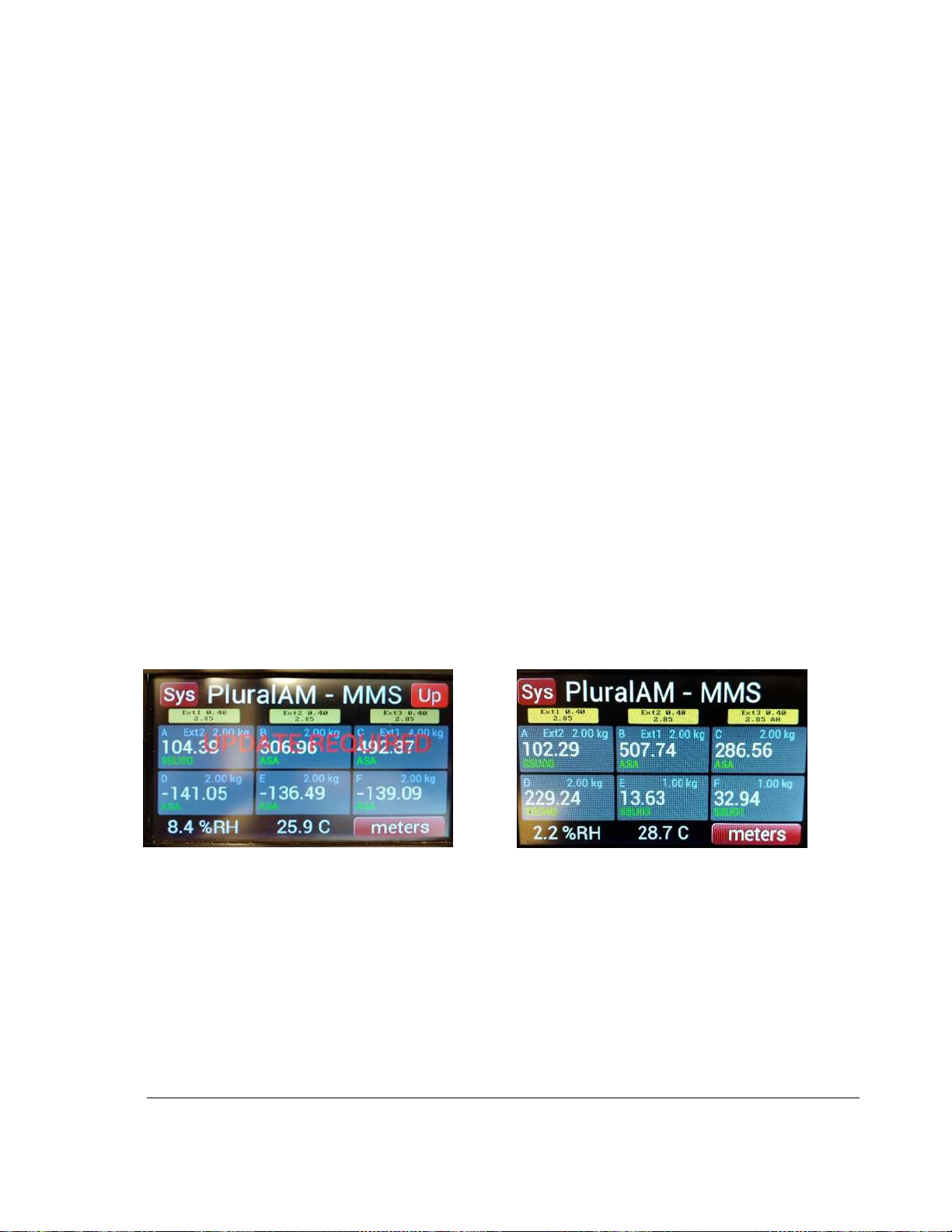
10.3 MMS Touch Screen Control
The touchscreen displays live readouts from the MMS’s 6 material feed storage positions, and
configuration data of the printer’s 3 nozzles, and prompts you when printer configuration or material
changes need to be made on the printer (as entered into the MMS dashboard application).
Figure 10.3.1 MMS – Update Required
Figure 10.3.2 MMS Touch Screen
10.4 MMS Dashboard
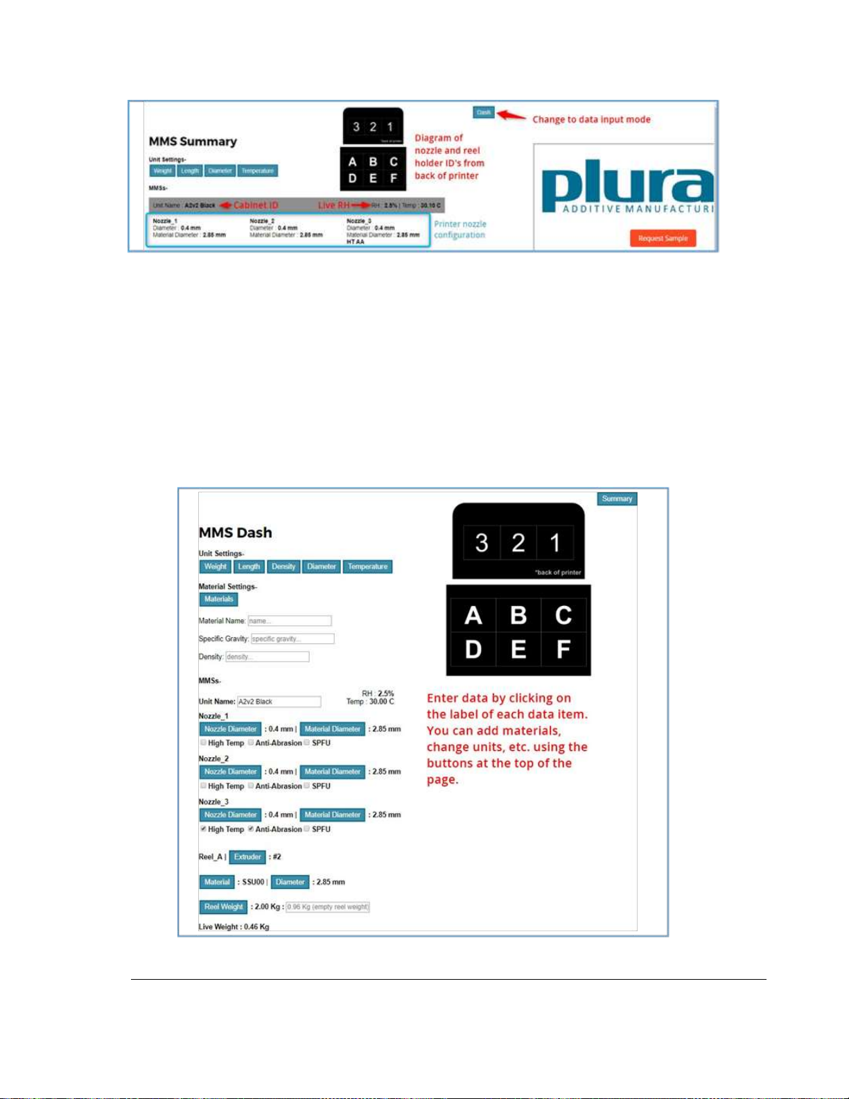
Click the Dash button if needed to switch to the data entry mode to add materials, set spools sizes and
store nozzle configuration information.
Page 43
39
TRAK Machine Tools
Southwestern Industries, Inc.
TRAK 3ntr 3D Printers – Printer & MMS Operation Quick Start Guide
Figure 10.4.1 Locating the MMS Dash Button
On the Dash page you can enter additional materials and edit any existing information. Remember that
you’ll need to know the specific gravity or density of each material entered to get reasonably accurate
material remaining estimations.
Remaining filament on each spool is calculated by using the empty weight of the spool along with the live
weight and material information entered for that spool. The server keeps a running average of the empty
spool weight, so if you know an empty spool weight has changed enter it into the field for the spool,
otherwise no entry will use the default average empty spool weight for that spool size.
After you make changes on the Dash page, the cabinet’s touchscreen will prompt you to confirm that the
changes have been made on the printer to ensure that the actual setup matches the MMS Server’s data.
Figure 10.4.2 MMS Dash
Page 44
40
TRAK Machine Tools
Southwestern Industries, Inc.
TRAK 3ntr 3D Printers – Printer & MMS Operation Quick Start Guide
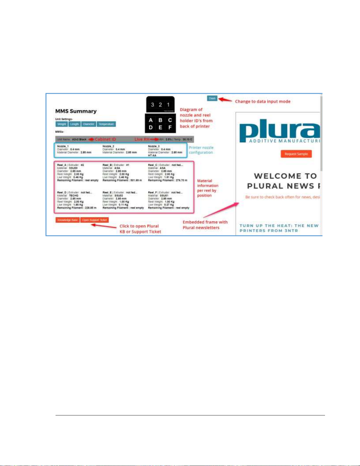
NOTE - The material positions and feeder numbers are as viewed from the back of the printer and are
labeled as indicated by the graphic on the MMS page.
The “Summary View” of the MMS Dash gives you an overview of the current configuration.
Figure 10.4.3 MMS Dash “Summary View”
10.4.1 Accessing the MMS Dashboard over a network
The dashboard is a server application that can be accessed over the network with standard web
browsers. To access the MMS Dashboard, enter the print server’s IP address followed by :3000, for
example: 100.1.100.85:3000. If the MMS server has not been set-up or connected properly, or to find
the printer server IP address, refer to the section: MMS Server Connection and Set-Up.
Page 45
41
TRAK Machine Tools
Southwestern Industries, Inc.
TRAK 3ntr 3D Printers – Printer & MMS Operation Quick Start Guide
11 Print Parts from an SD Card
In this section, we will print a test part from the SD Card. The same process will apply for printing other
parts from the SD card.
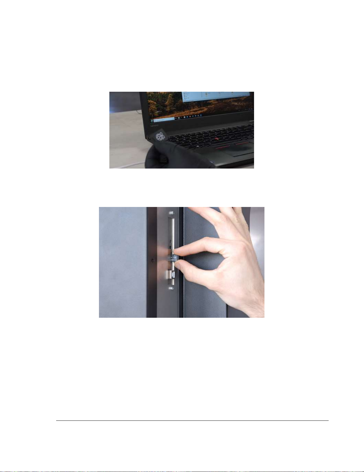
1) Remove the SD Card from the PC adapter (if applicable)
Figure 11.1 PC adapter for SD Card
2) Insert an SD Card containing the desired g-code files into the SD card port in the rear of the
printer. Feel for the card alignment slots in the center. Insert the card carefully until you feel the
spring resistance. Push it in till it clicks securely.
Figure 11.2 Inserting SD Card into Printer
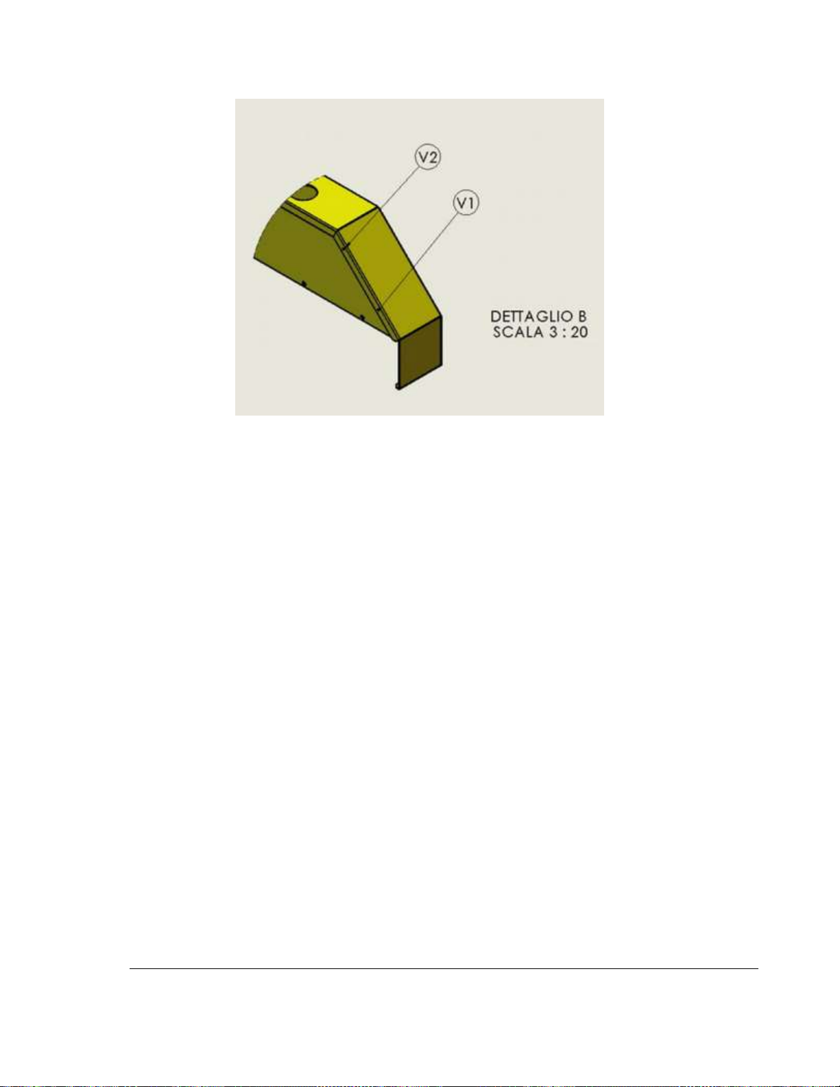
CAUTION: Insert the SD card carefully. It can easily miss the engagement slots and fall into the
printer. If the SD card falls into the printer, you will have to remove the side sheet metal cover to
retrieve it. To remove the side sheet metal cover, you must remove all the fasteners on the
outside as well as two screws in the inside of the printer.
Page 46
42
TRAK Machine Tools
Southwestern Industries, Inc.
TRAK 3ntr 3D Printers – Printer & MMS Operation Quick Start Guide
Figure 11.3 Side Cover Inner Screw Locations
3) Load the filament for the material specified in the g-code file of the program being printed.
(ABS/ASA material supplied with the new printer matches for calibration and test part prints)
4) Verify there is enough filament on the spools to complete the print. If not, change the spool
before starting, or prepare a back-up spool for a change during printing using the Print Pause
function.
5) Verify the nozzle sizes installed in the printer match those specified within the g-code (print
program) file. New printers are delivered with 0.4 mm nozzles that are compatible with
calibration and supplied test part prints.
6) Check that the filament feeder handles are in the engaged position.
7) Purge the nozzles before printing. Verify nozzle flow is acceptable. If not, perform cleaning
procedure using nylon material and the cleaning function from the Prepare menu. Replace
nozzles or perform other troubleshooting, as required.
8) Check and Clean printer tray. Remove any remaining print filament. Wipe down the printer
surface plate with acetone or approved cleaner as required. Verify the printer tray is properly
positioned and secured in place with magnets.
9) Close the printer access door.
10) Pre-Heat the Printer Bed (if desired to save time). If necessary, use the printer controls to
adjust/set a different temperature for specific materials.
11) Pre-Heat the Printer Chamber (if desired to save time) If necessary, use printer controls to adjust
chamber pre-heating temperature.
CAUTION: DO NOT use this function if the printer is loaded with low meting point polymers
(such as PLA) filament may swell making it impossible to remove from piping and/or extruders.
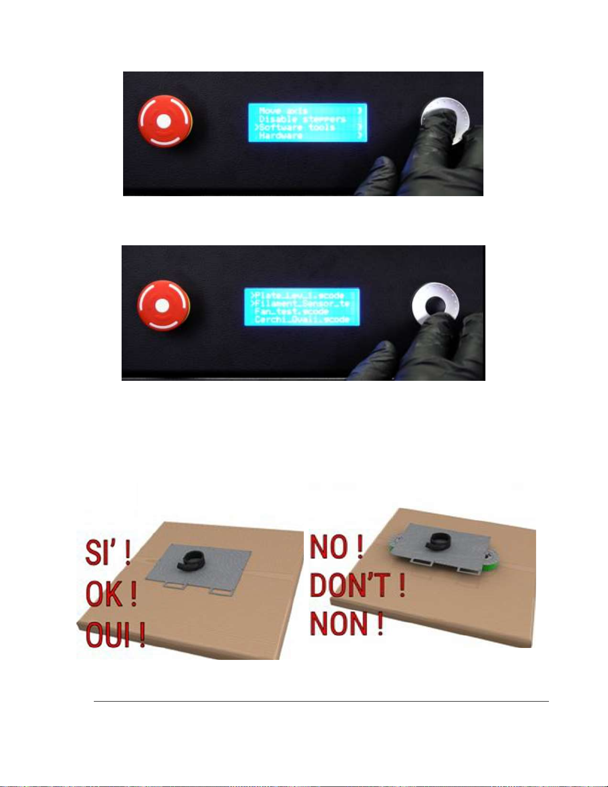
12) Use the front panel to navigate to: Prepare > Software Tools menu,
Page 47
43
TRAK Machine Tools
Southwestern Industries, Inc.
TRAK 3ntr 3D Printers – Printer & MMS Operation Quick Start Guide
Figure 11.4 Selecting Software Tools from Prepare Menu
13) Browse until you find the desired g-code file. Select to begin printing.
Figure 11.5 Browsing g-code files in Software Tools Menu
14) Monitor the print from the info screen and by observing the print in process. Experienced print
operators may choose to make print process adjustments mid-print using the Tune Menu.
15) Let the part cool within the printer if possible. If necessary, remove the print tray and allow it to
cool outside the printer. If you remove the print tray while hot, be sure to support it correct to
avoid deforming the part/tray.
Figure 11.6 Printer Tray Cooling Support
Page 48
44
TRAK Machine Tools
Southwestern Industries, Inc.
TRAK 3ntr 3D Printers – Printer & MMS Operation Quick Start Guide
16) Remove the part following the same instructions for the test cone. Avoid using sharp blades or
spatulas, they risk damaging the tray surface.
11.1 Stop/Pause Printing
During Printing, if you need to stop or pause printing, simply select the appropriate menu item from the
printing menu.
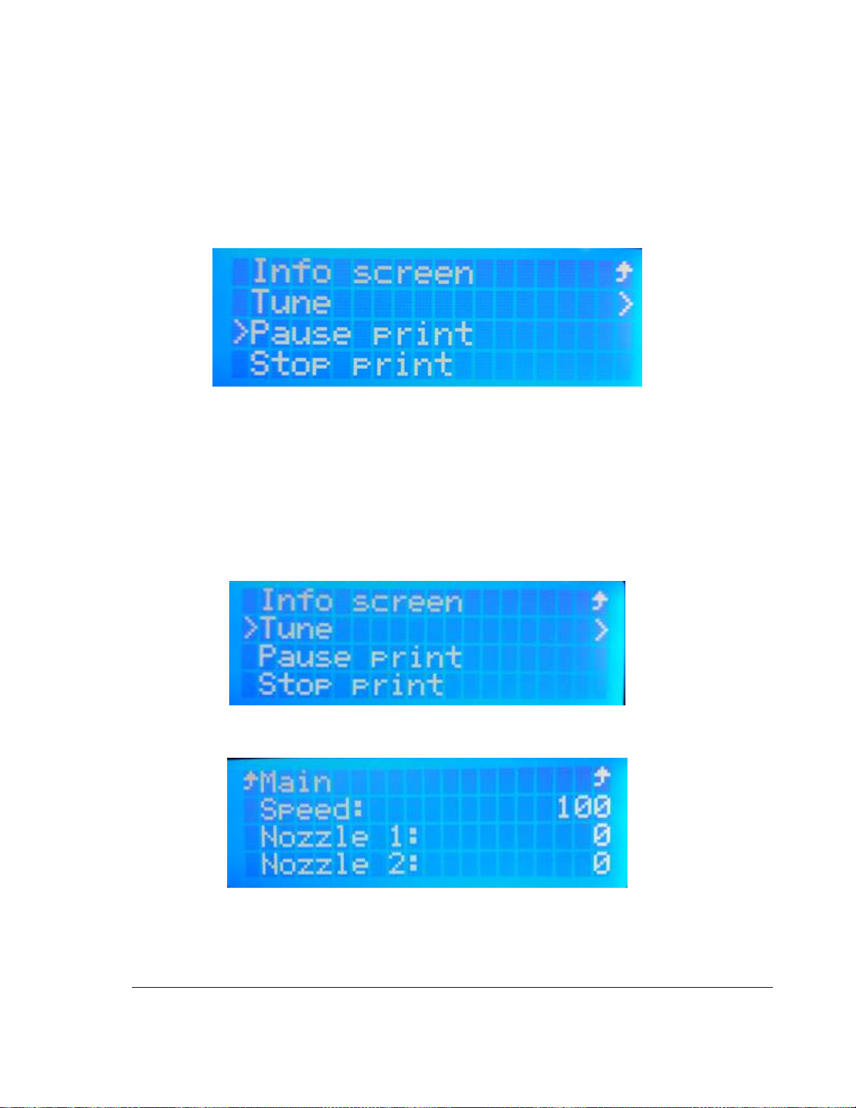
Figure 11.1 Printing Menu Selections
11.2 Tune Menu – Adjust Process Parameters Mid-Print
The Tune menu becomes available on the Info screen during printing and offers options to change
nozzle, bed, and/or chamber temperatures, as well as program running (printing) speed.
CAUTION – Only experienced print operators should use the Tune menu during printing
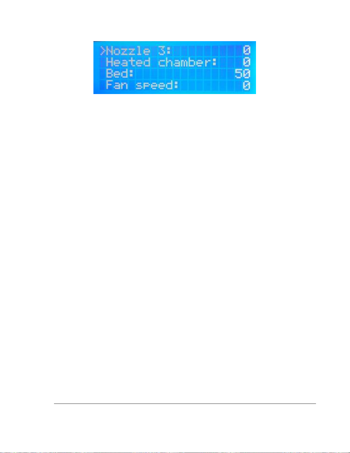
1) Scroll down the Info screen, select the Tune, and press the black jogwheel button to Tune
Figure 11.1 Selecting Tune from Info Screen Menu
2) Scroll down the Tune menu and then select the tuning parameter desired.
Figure 11.2 Tune Menu, Screen 1
Page 49
45
TRAK Machine Tools
Southwestern Industries, Inc.
TRAK 3ntr 3D Printers – Printer & MMS Operation Quick Start Guide
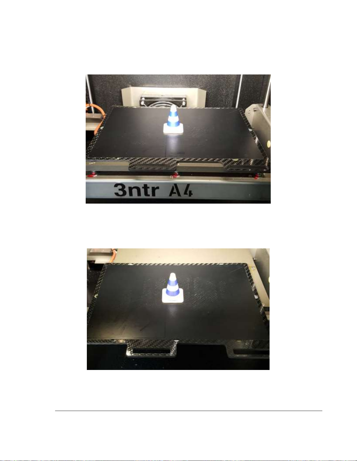
Figure 11.3 Tune Menu: Screen 2
NOTE: Global printing parameters are directly available in the Tune menu. To adjust nozzle
temperatures, you must individually select the nozzles one by one, then tune.
3) Select the desired Tuning parameter, then enter/adjust as desired. Repeat for additional
parameters as required.
Page 50
46
TRAK Machine Tools
Southwestern Industries, Inc.
TRAK 3ntr 3D Printers – Printer & MMS Operation Quick Start Guide
12 Remove a Printed Part from the Printer
This section details the process to remove a printed part from the printer.
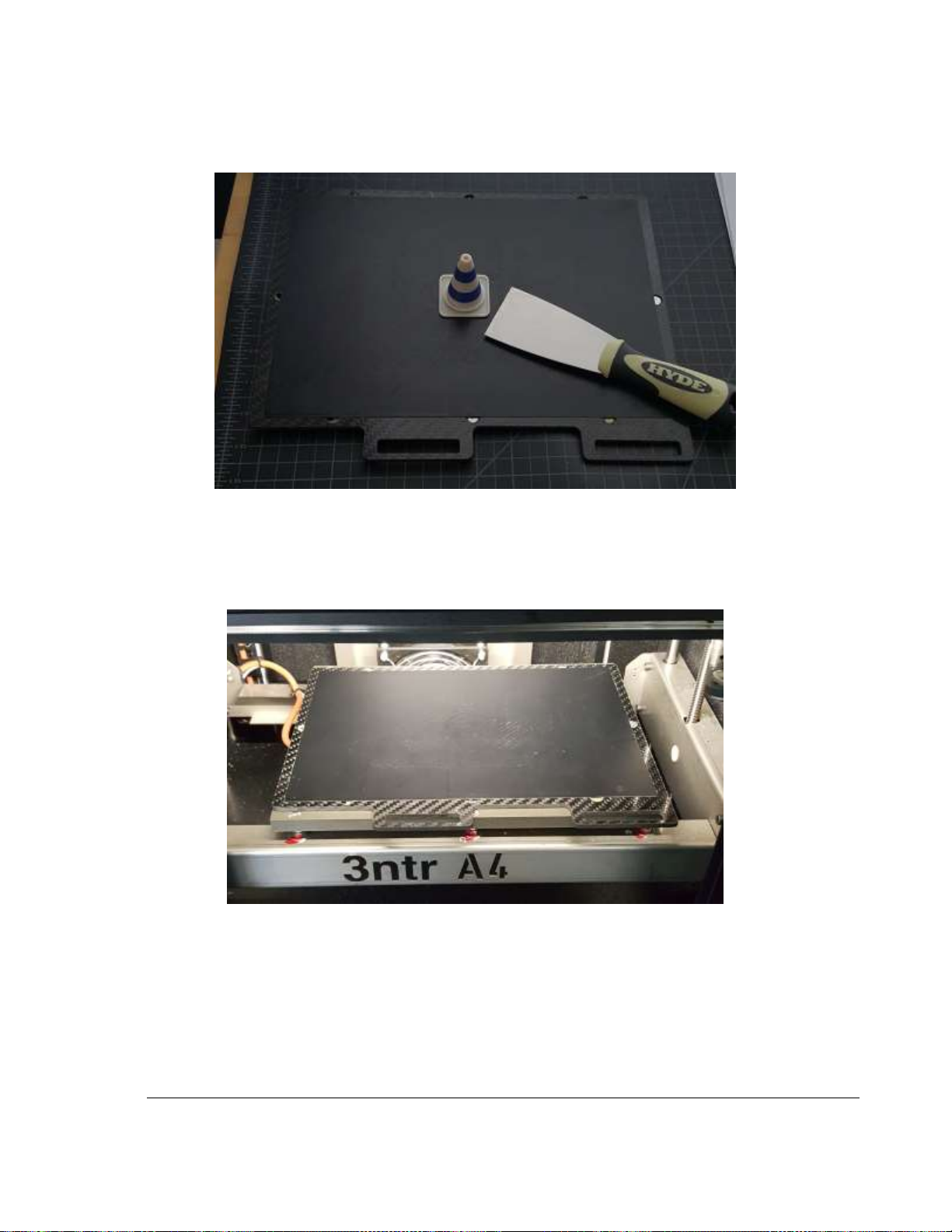
Figure 12.1 Printed Part (Cone) on Printer Plate
1) Remove the Print Surface Plate. Grab the handles of the removable, carbon fiber finished print
surface plate and pull horizontally toward you. A slight upward force will overcome the magnetic
force holding the print plate in place.
2) Place the printer surface plate on a clean table or simply pull it partially out of the printer.
Figure 12.2 Printer Plate partially removed from Printer
Page 51
47
TRAK Machine Tools
Southwestern Industries, Inc.
TRAK 3ntr 3D Printers – Printer & MMS Operation Quick Start Guide
3) Remove the sample cone from the print plate. Often it can be just pried up and off the print
surface by hand (when cool). Otherwise remove it by prying it upward using the supplied
scraper to break the raft free, then remove the cone.
Figure 12.3 Printed Part (Cone) and supplied scraper tool
4) Check and Clean the Printer Tray. Remove any remaining print filament. Wipe down with acetone
or approved cleaner as required.
5) Replace the Printer Tray. Replace the printer bed into the printer with the reverse process used
to remove it. Ensure it locks in place with the magnetic mounts.
Figure 12.4 Printer surface plate re-installed in printer
6) Close the printer access door.
Page 52

48
TRAK Machine Tools
Southwestern Industries, Inc.
TRAK 3ntr 3D Printers – Printer & MMS Operation Quick Start Guide
13 Print Server Overview
The print server, once set-up and connected, enables remote monitoring of the printer via a webcam and
full remote control of all manual and automatic functions of the printer. The print server type shipped
with your printer may vary depending on whether an MMS unit is also ordered.
CAUTION - An operator present at the machine may not be aware of manual printer control commands
sent remotely. Before using Print Server to control the machine or print - ensure all personnel and/or
print operators are either not present or notified in advance of remote-control operation.
CAUTION - Use the webcam or an operator on-site to ensure all aspects of the printer status/condition
are suitable for the remote operational commands issued from Print Server.
• Nozzles/Extruders and all associated hardware must be installed and connected.
• Filament loaded and feed handles locked (if printing)
• Printer tray should be empty, clean, and locked into position.
• Access panels should be in place and the access door closed.
Page 53

49
TRAK Machine Tools
Southwestern Industries, Inc.
TRAK 3ntr 3D Printers – Printer & MMS Operation Quick Start Guide
14 Maintain your printer for subsequent prints
Before Each Print:
• Clean the printer tray and ensure it is secured in the correct location
• Verify the filaments loaded matches the material profiles specified during slicing
• Determine if enough filament remains to complete the print
• Make sure the feeder handles are in the engaged position for all extruders
• Purge nozzles and verify acceptable flow conditions
Each Month:
• Check cooling liquid levels. Refill if needed using only supplied (RED) coolant. Do not dilute.
• Nozzle Check – Clean with Nylon and Cleaning function from LCD/Replace nozzles if needed.
• Clean all the feeder rollers
Every 6 Months OR If Printed Part Quality Degrades)
• Z calibration
• XY calibration
• Heat Exchanger cleaning
• Firmware version check
• By Factory Trainer Personnel: Rail lubrication, Belt tensioning, Screw/Bolt tightening, Feeder
roller pressure check, Heater temperature.
NOTE – Please refer to Printer & MMS Guide for a complete list of calibration procedures and detailed
instructions.
Page 54
50
TRAK Machine Tools
Southwestern Industries, Inc.
TRAK 3ntr 3D Printers – Printer & MMS Operation Quick Start Guide
15 TRAK Warranty Policy
Southwestern Industries, Inc
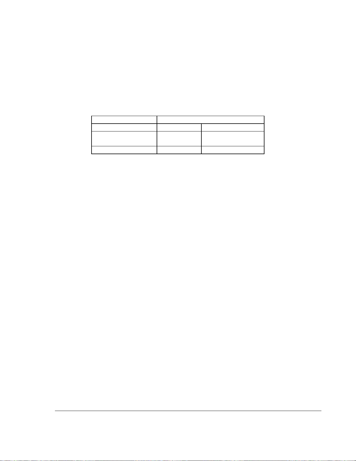
Warranty
TRAK products are warranted to the original purchaser to be free from defects in workmanship and
materials for the following periods:
Product
Warranty Period
Materials
Factory Labor
New
TRAK/ProtoTRAK
1 Year
1 Year
Any EXCHANGE Unit
90 Days
90 Days
The warranty period starts on the date of the invoice to the original purchaser from Southwestern
Industries, Inc. (SWI) or their authorized distributor.
If a product, subsystem or component under warranty fails, it will be repaired or exchanged at our option
for a properly functioning unit in similar or better condition. Such repairs or exchanges will be made FOB
Factory/Los Angeles or the location of our nearest factory representative or authorized distributor.
Disclaimers of Warranties
• This warranty is expressly in lieu of any other warranties, express or implied, including any
implied warranty of merchantability or fitness for a particular purpose, and of any other obligations
or liability on the part of SWI (or any producing entity, if different).
• Warranty repairs/exchanges do not cover incidental costs such as installation, labor, freight, etc.
• SWI is not responsible for consequential damages from use or misuse of any of its products.
• TRAK products are precision mechanical/electromechanical/electronic systems and must be
given the reasonable care that these types of products require.
• Accidental damage, beyond the control of SWI, is not covered by the warranty. Thus, the
warranty does not apply if a product has been abused, dropped, hit or disassembled.
• Improper installation by or at the direction of the customer in such a way that the product
consequently fails, is considered to be beyond the control of the manufacturer and outside the
scope of the warranty.
Rev 091514
 Loading...