

Page 1
Quick Start
BlueTOAD Spectra
and
BlueTOAD Spectra RSU
Revision 02, May 2019
Page 2

Copyright and Trademarks
Published: 31 May 2019
© 2019 TrafficCast International, Inc. All rights reserved.
TrafficCast®, BlueTOAD®, TrafficCarma™ and all other associated logos are trademarks of TrafficCast
International, Inc.
The Bluetooth® word mark and logos are registered trademarks owned by the Bluetooth SIG, Inc. and any
use of such marks by TrafficCast International, Inc. is under license. Other trademarks and trade names are
those of their respective owners.
Contact Information
Headquarters
TrafficCast International, Inc.
1800 Deming Way
Suite 100
Middleton, WI 53562
USA
Telephone: 1-608-713-9300
Support
BlueARGUS On-Going Operations Website: https://bluetoad.trafficcast.com
TrafficCast Support Website: https://trafficcast.zendesk.com
TrafficCast Support Telephone: 1-608-713-9299
TrafficCast Quick Start—BlueTOAD Spectra and Spectra RSU
ii Revision 02 May 2019
Page 3

Contents
Copyright and Trademarks ........................................................................................................................................ ii
Contact Information .................................................................................................................................................. ii
Headquarters ........................................................................................................................................................... ii
Support .................................................................................................................................................................... ii
Contents ...................................................................................................................................................................... iii
Glossary ....................................................................................................................................................................... v
1. Introduction ............................................................................................................................................................ 1-1
Purpose .................................................................................................................................................................... 1-1
Features Affect Deployment ................................................................................................................................. 1-1
Components of the different BlueTOAD Spectra and BlueTOAD Spectra RSU ....................................... 1-2
Compatible Traffic Controllers ........................................................................................................................ 1-2
Contents of the Chapters in this Quick Start ................................................................................................. 1-2
2. BlueTOAD Spectra Deployment ........................................................................................................................ 2-1
Purpose .................................................................................................................................................................... 2-1
Supporting Equipment ...................................................................................................................................... 2-1
Procedures ............................................................................................................................................................... 2-1
Pre-Install Evaluation ........................................................................................................................................ 2-1
Configure the Ethernet BlueTOAD Web IP ................................................................................................. 2-2
Layout Guidelines .............................................................................................................................................. 2-4
Pre-Installation Testing ..................................................................................................................................... 2-4
Field Installation ................................................................................................................................................. 2-6
Field Installation for Ethernet PoE Detectors .............................................................................................. 2-7
Field Installation for BlueTOAD Spectra Solar Cellular Detectors ......................................................... 2-12
Test after you Mount a BlueTOAD Spectra PoE Detector to a Pole ..................................................... 2-18
Confirm Network Connectivity and Data Collection ................................................................................ 2-18
Troubleshooting ............................................................................................................................................... 2-20
Record Keeping ................................................................................................................................................ 2-21
Data and Device Management via BlueARGUS ......................................................................................... 2-21
On-Going Operations / On-Going Customer Support ............................................................................ 2-21
TrafficCast Quick Start—BlueTOAD Spectra and Spectra RSU
Revision 02 May 2019 iii
Page 4

3. BlueTOAD Spectra RSU Deployment ............................................................................................................... 3-1
Purpose .................................................................................................................................................................... 3-1
Supporting Equipment ...................................................................................................................................... 3-1
Procedures ............................................................................................................................................................... 3-1
Layout Guidelines .............................................................................................................................................. 3-2
Pre-Install Evaluation and Setup ..................................................................................................................... 3-2
How to Set Up the Traffic Controller Before Field Deployment .............................................................. 3-3
Factory “Stock” RSU Configuration Procedure—using the BlueTOAD RSU Configuration Utility ........ 3-6
Confirm that the BlueTOAD Spectra RSU is Broadcasting SPaT, MAP and BSM Data .................... 3-11
Field Installation of a BlueTOAD Spectra RSU ......................................................................................... 3-16
Testing a BlueTOAD Spectra RSU After Field Installation ...................................................................... 3-22
4. Appendix—How to Create an RSU MAP File ................................................................................................. 4-1
Objective .................................................................................................................................................................. 4-1
Material Requirements ........................................................................................................................................... 4-1
Map File Creation Procedure ................................................................................................................................ 4-1
5. Appendix—How to Manually Configure a BlueTOAD Spectra RSU .......................................................... 5-1
Supplement to Factory “Stock” RSU Configuration Procedure (Pages 3-6 thru 3-11) ............................... 5-1
How to Upload a MAP File .................................................................................................................................. 5-3
Confirm that the BlueTOAD Spectra RSU is Broadcasting SPaT, MAP and BSM Data ...................... 5-5
6. Appendix—Blue TOAD Spectra RSU Specifications and Site Requirements Form .................................. 6-1
RSU Specifications ................................................................................................................................................. 6-1
BlueTOAD Spectra RSU Network Security Statement ............................................................................... 6-1
Bandwidth/Data Usage..................................................................................................................................... 6-1
FCC Individual Device RSU License Details ................................................................................................ 6-1
BlueTOAD Spectra RSU – Recommended Network Configuration Implementation ........................... 6-2
BlueTOAD Spectra RSU Site Requirements Form .......................................................................................... 6-3
TrafficCast Quick Start—BlueTOAD Spectra and Spectra RSU
iv Revision 02 May 2019
Page 5

Glossary
In the glossary below, terms are listed in alphabetical order along with their meanings. Below is an example
of acronyms used in text.
Example: In the future, each automobile will be a Connected Vehicle (CV) equipped with
an Onboard Unit (OBU) that will communicate with the external traffic infrastructure.
Term Meaning
AGL Above Ground Level
ATIS American Traveler Information Systems
AWS Amazon Web Services
BlueARGUS Web-based software to monitor BlueTOAD detectors
BlueTOAD Bluetooth® Travel time Origin And Destination
BSM
CAT-5 Cable
CV / CAV Connected Vehicle / Connected and Autonomous Vehicles
DIAM DENSO International America, Inc.
Discoverable/
Non-Discoverable
DNS UDP
DSRC Dedicated Short Range Communications
Egress Going out of (leaving) an intersection
EIRP Effective Isotropic Radiated Power
EMAC Ethernet Media Access Controller
Basic Safety Message—every 0.10 second, a connected vehicle (CV) broadcasts its vehicle type,
speed, location, direction and approach relative to an intersection.
Category 5 cable, a twisted pair cable for computer networks. The cable standard provides
performance of up to 100 MHz and is suitable for 1000BASE-T (Gigabit Ethernet). This is also
called an “Ethernet Cable” or a “LAN Cable.”
Discoverable = Bluetooth device searching to Pair with another Bluetooth device
Non-Discoverable = two Paired Bluetooth devices
Domain Name System—a hierarchical and decentralized naming system for resources connected to
the Internet or a private network. User Datagram Protocol—an alternative comm protocol to TCP
ERM Event Reporting Message
FCC Federal Communications Commission
Free-TEXT Custom text you type to create a message or part of a message for a TIM
GPS Global Positioning System
HTML Hypertext Markup Language
IEEE Institute of Electrical and Electronics Engineers
TrafficCast Quick Start—BlueTOAD Spectra and Spectra RSU
Revision 02 May 2019 v
Page 6

Term Meaning
Index-phrase
Ingress Going into (entering) an intersection
IoT Internet of Things
IP address Internet Protocol address—host or network interface identification and location addressing
ITIS
Standard text used create a message or part of a message for a TIM, defined by ITIS and assigned a
code number—whose meaning is known internationally.
International Traveler Information Systems. For ITIS phrase lists to use in creation of TIMs, use
SAE publication SAE J2540-2. To order a copy, go to
https://www.sae.org/standards/content/j2540_200207/
ITS Intelligent Transport System
LAN/WAN Local Area Network/Wide Area Network
MAP
NTCIP National Transportation Communications for Intelligent Transportation System Protocol
NTCIP Support
Map Data Message— intersection geography and line definitions of the intersection or street.
An RSU transmits one MAP message per second to OBUs.
ITS Standard NTCIP 1202 Object Definitions used for communication with Actuated Traffic Signal
Controller (ASC) Units
NTP Network Time Protocol
OBU Onboard Unit
O/D Origin/Destination
Omni-directional Receiving signals from or transmitting in all directions
PCB Printed Circuit Board
PoE Power over Ethernet
PuTTY SSH Client terminal program for Microsoft Windows
RDS Radio Data Service (on FM 57 kHz subcarrier)
RJ-45 Port Registered Jack (RJ) is a standardized telecommunication network interface
RSU Road Side Unit
RTCM
SCMS
Radio Technical Commission for Maritime services. In the United States, the Federal
Communications Commission uses RTCM standards to specify Differential GPS systems for DSRC.
Security Certificate Management System—developed by a consortium of automakers and the United
States Department of Transportation (USDOT) as a leading candidate for a vehicle-to-vehicle (V2V)
security system in the United States.
Simple Network Management Protocol—used to monitor and manage devices on networks.
SNMP
vi Revision 02 May 2019
Typically, SNMP uses User Datagram Protocol (UDP) transport layer (layer 4) as its transport
protocol.
TrafficCast Quick Start—BlueTOAD Spectra and Spectra RSU
Page 7

Term Meaning
SPaT Signal Phase and Timing
SRM Signal Request Message
SSH Client A software program which uses the Secure Shell protocol to connect to a remote computer.
SYSLOG A way for network devices to send event messages to a logging server, known as a Syslog server
TCP Transmission Control Protocol
Traveler Information Message—delivered to Connected Vehicles and TravelSMART Mobile App—
TIM
TIM Zone A geographic area in the shape of a Polygon, Polyline or Circle, defined to receive TIMs
TMC Traffic Management Center
UPER Unaligned Packed Encoding Rules
URL Uniform Resource Locator
a personal message board about local conditions. TIMs describe traffic-related events of interest to
travelers and other traffic practitioners.
Users Authorized access through secure login to software application
Win SCP File transfer application
TrafficCast Quick Start—BlueTOAD Spectra and Spectra RSU
Revision 02 May 2019 vii
Page 8

For your notes:
TrafficCast Quick Start—BlueTOAD Spectra and Spectra RSU
viii Revision 02 May 2019
Page 9
1. Introduction
Purpose
This Quick Start gives procedures to deploy TrafficCast BlueTOAD Spectra units. Included are procedures
to confirm Network Connectivity and Data Collection. Chapter 2 explains how to deploy the three different
BlueTOAD Spectra detectors and Chapter 3 explains how to deploy a BlueTOAD Spectra RSU.
Chapter 4 thru Chapter 6 are Appendices.
Features Affect Deployment
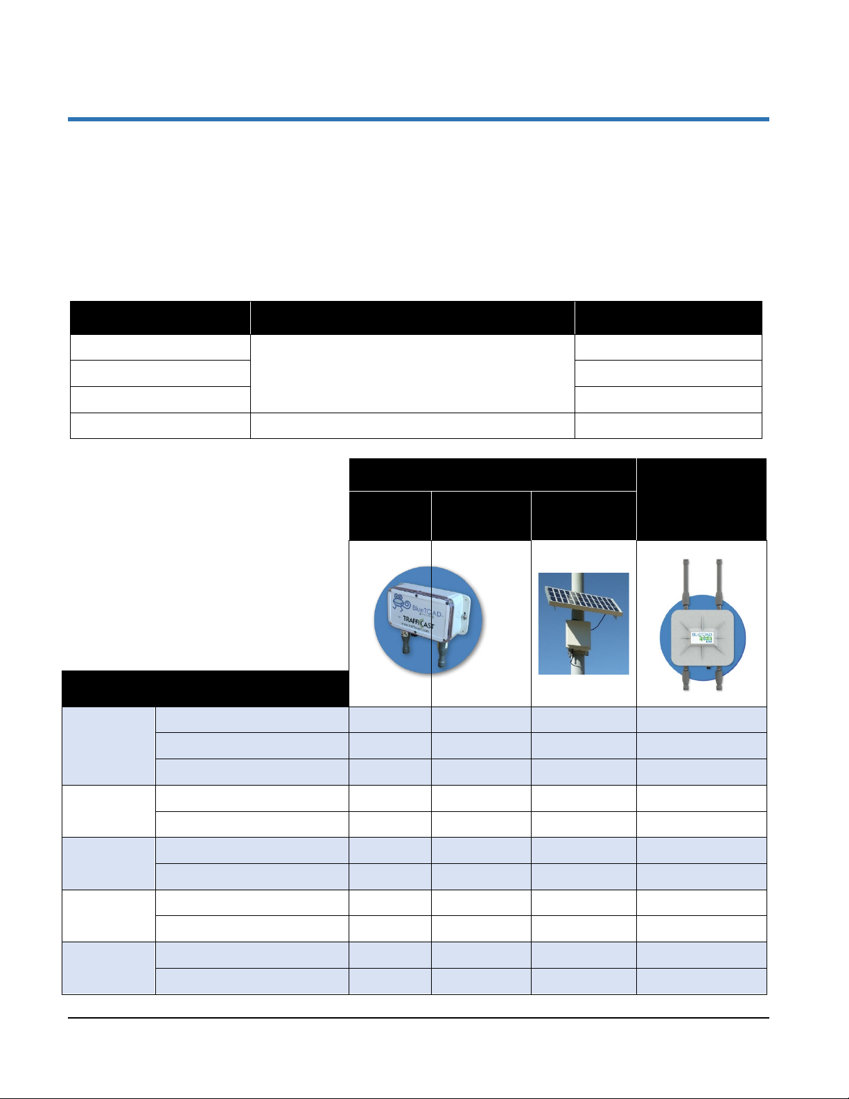
The tables below describe the four BlueTOAD Spectra units and give their main features.
BlueTOAD Spectra Unit Function Part Number
Ethernet PoE
Ethernet Cellular PoE BT-CELL-SPECTRA-POE
Solar Cellular BT-CELL-SPECTRA-85
RSU Ethernet PoE Receives and transmits Detection, CV and SPaT Data BT-SPECTRA-RSU
Detects and transmits Data for Speed and Travel Time
BT-ETH-SPECTRA-POE
Features affect deployment of each unit.
Example: Three of the four units are
powered by Power over Ethernet
Ethernet
PoE
BlueTOAD Spectra
Ethernet
Cellular PoE
Solar Cellular
BlueTOAD
Spectra RSU
Ethernet PoE
(PoE) and thus must be connected to a
roadside Traffic Cabinet or equivalent
source for their power and
communications; a Solar Cellular,
however, is stand-alone because it is
powered by Solar and communicates
directly over the Cellular Network.
Features
Speed and Travel Time X X X X
Types of Data
Processed
Connected Vehicle BSM X
Traffic Controller SPaT X
Data is
Transmitted
Powered by
Field
Installation
Weight
TrafficCast Quick Start—BlueTOAD Spectra and RSU
Revision 02 May 2019 1-1
Through Agency Servers X X
Through the Cellular Network X X
Power over Internet (PoE) X X X
Solar-Charged Battery X
Near Roadside Traffic Cabinet X X X
Stand-Alone X
Weights with brackets <5 lbs. <5 lbs. <9 lbs.
Weight with Battery <40 lbs.
Page 10
Introduction
Components of the different BlueTOAD Spectra and BlueTOAD Spectra RSU
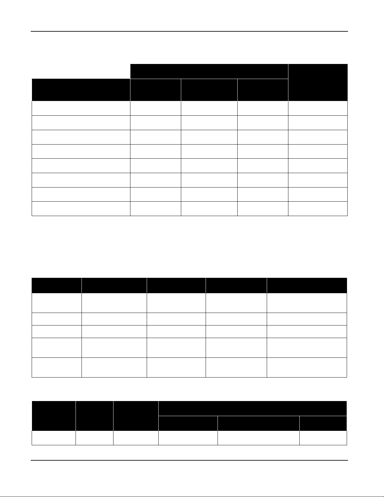
The table below shows hardware and software accessories for each of the four BlueTOAD Spectra units.
BlueTOAD Spectra
Item
PoE Injector + Power Supply X X X
Shielded CAT-5 or CAT-6 Cable X X X
Mounting Bracket + Fasteners X X 2 X
Cable Band X X 2 X
Solar Panel + Mounting Hardware X
Battery X
BlueARGUS Software X X X X
Traffic Controller (see next table) X
An “X” under a unit indicates that the related Item is a component of that unit.
A “2” under a unit indicates that there are two of the related Items in that unit.
Ethernet
PoE
Ethernet
Cellular PoE
Solar
Cellular
BlueTOAD
Spectra RSU
Ethernet PoE
Compatible Traffic Controllers
For operation of the BlueTOAD Spectra RSU Ethernet PoE, you must have a Traffic Controller.
The table below lists the Traffic Controllers that you can use with the BlueTOAD Spectra RSU.
Manufacturer Model Software SPaT Support NTCIP1202 Support
Econolite
Intelight 2070LDX ATC Maxtime CV Yes Yes
McCain NEMA ATC FlexRM Yes Yes
Siemens 2070-1C/M60
Trafficware
Contents of the Chapters in this Quick Start
Chapter 1 Chapter 2 Chapter 3
Introduction Spectra Spectra RSU Create a MAP file Manually Configure RSU RSU Docs.
ASC3/Cobalt2100/1000/RM
980/NEMA
ATC/2070-1C
Asc3app/Cobalt Yes Yes/Yes
SEPAC ECOM/
SEPAC NTCIP
Apogee Yes Yes
Chapter 4 Chapter 5 Chapter 6
Yes No/Yes
Appendices
TrafficCast Quick Start—BlueTOAD Spectra and Spectra RSU
1-2 Revision 02 May 2019
Page 11
Important: Contact TrafficCast BlueTOAD support, 1-608-713-9299, before
you install any equipment to make sure all devices have been correctly tested.
2. BlueTOAD Spectra Deployment
Purpose
The procedures in this chapter tell you how to deploy a TrafficCast BlueTOAD Spectra speed/travel time
detector system and then start to collect data. We assume you are familiar with the Ethernet-based
communications network of your Agency and the supporting equipment listed below.
Supporting Equipment
• Windows PC and Ethernet Cables1
• Portable Laptop, Apple iPad or Android-based tablet with wireless Internet access
• Web browser – Google Chrome or Windows Edge are preferred
• TrafficCast BlueTOAD Spectra detector
Procedures
The procedures that follow tell you how to deploy and test a BlueTOAD Spectra speed/travel time detector
system.
Note: After notice to proceed is approved, TrafficCast and key collaborative team personnel will
work with your Agency to create a formal deployment, implementation and operations plan
document for your BlueTOAD system.
Pre-Install Evaluation
1. Before you install a BlueTOAD system, make sure things are ready at the installation sites.
Location – Prepare a sight survey of intersection locations that have been selected to deploy
BlueTOAD Spectra detectors.
Identify power sources available in the traffic cabinets.
Before you install a BlueTOAD Spectra:
• Make sure a site survey checklist has been completed for all locations.
• Make sure you have all the necessary parts for the system. Refer to the table
on Page 1-2 for a list of the items included with your type of BlueTOAD
Spectra detector.
1
Ethernet Cables are NOT necessary for the BlueTOAD Spectra Solar Cellular detector.
TrafficCast Quick Start—BlueTOAD Spectra and RSU
Revision 02 May 2019 2-1
Page 12

BlueTOAD Spectra Deployment
Traffic Network –Evaluate the existing network.
Fiber and/or Ethernet based? Or, no network communications?
Confirm that the network settings (for example, IP address, gateway, subnet mask,
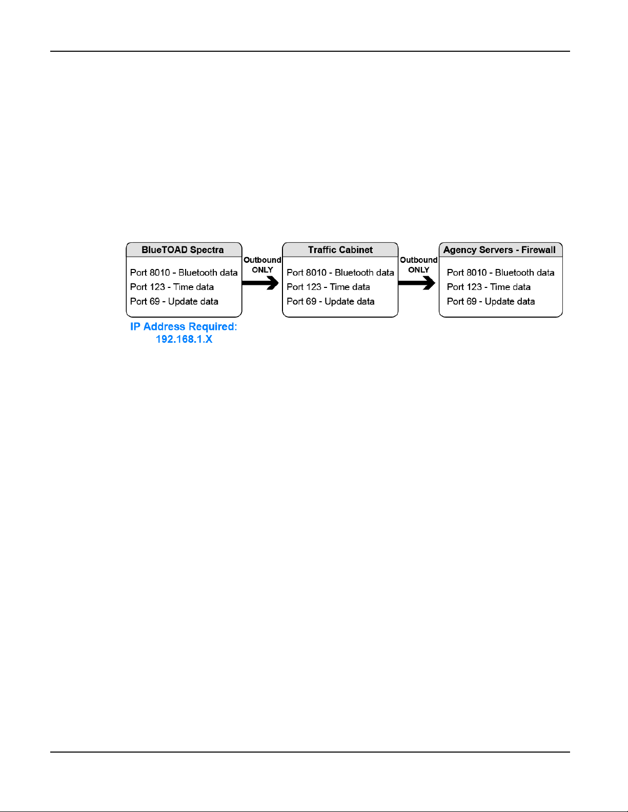
and DNS) are correctly set and that all ports (69, 123, 8010) are open and set for
outbound data traffic.
What is the IP address assigned to the BlueTOAD Spectra?
Configure the Ethernet BlueTOAD Web IP
2. To configure the Web IP of an Ethernet BlueTOAD PoE2:
a. Connect the Ethernet BlueTOAD™ to a switch or laptop Ethernet port.
Note: With this connection, an Ethernet BlueTOAD can auto-negotiate.
b. Power ON the Ethernet BlueTOAD™.
c. Log into the BlueTOAD Spectra detector:
i. Open a Web Browser (Google Chrome or Microsoft Edge is preferred).
ii. Enter the default BlueTOAD Spectra IP address (192.168.1.77) and URL
(http://192.168.1.77:8080/admin.cgi)
Note: If the IP address has been changed from the factory default, use the new IP
address to access the login website.
iii. For the configuration tool to proceed, you must use the username and password given
below at the default address:
Username: admin
Password: 77admin77
After login, the BlueTOAD Device Administration screen will open.
2
You configure the Web IP for a Spectra Ethernet PoE type detector but NOT for a Spectra Ethernet Cellular PoE or a Solar
Cellular detector. The cellular Spectra detectors broadcast directly to the TrafficCast National Servers over the cellular network,
bypassing the Ethernet-based Servers-Firewall of the Agency.
TrafficCast Quick Start—BlueTOAD Spectra and Spectra RSU
2-2 Revision 02 May 2019
Page 13
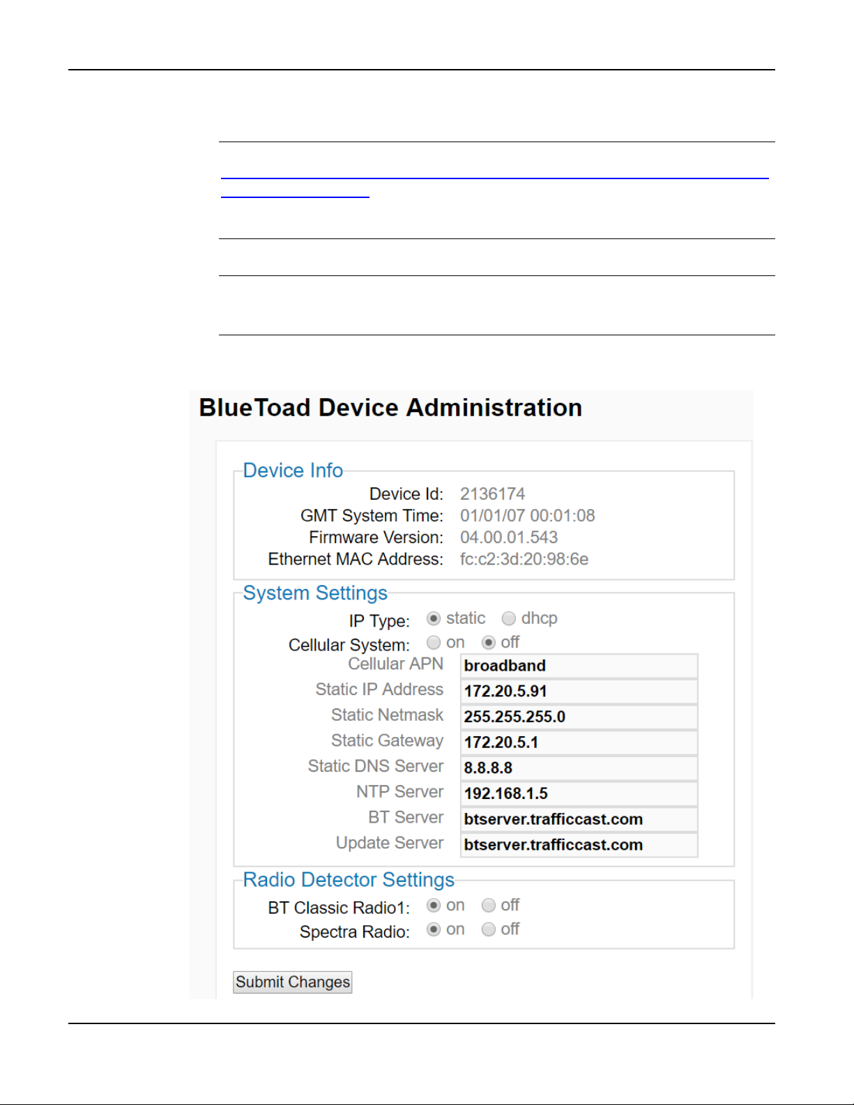
d. To change any of the fields in the System Settings area:
i. Enter the new value into each field.
Note: For a helpful workbook to keep a record of the values in each field, go to
https://trafficcast.zendesk.com/hc/en-us/articles/360015177732-Preprogramminginstallation-cheat-sheet
In the middle left of the page, select BlueTOAD Programming Cheat Sheet.xlsx
At the bottom left of the Excel page, select the Pre Installation Sheet tab.
ii. When done, click Submit Changes.
Important: If you change the IP address, keep a record of the new BlueTOAD
Spectra IP address because you must use the new IP address to log back into this
same device! Without the correct IP, you CANNOT log in.
iii. The BlueTOAD Spectra resets automatically.
BlueTOAD Spectra Deployment
TrafficCast Quick Start—BlueTOAD Spectra and Spectra RSU
Revision 02 May 2019 2-3
Page 14
BlueTOAD Spectra Deployment
Layout Guidelines
3. After you select the target road segment for speed/travel time data collection, use the guidelines that
follow to determine how many BlueTOAD detectors are necessary for your travel time study or
reporting objectives.
BlueTOAD has an effective omni-directional detection range of an approximately 300-foot
radius from the antenna.
The minimum recommended distance to space a BlueTOAD PoE or Cellular is every
0.25 mile.
Note: Power Control lets you reduce the detection zone to minimize overlap.
Thus, with Power Control, the minimum spacing could be less than 0.25 mile.
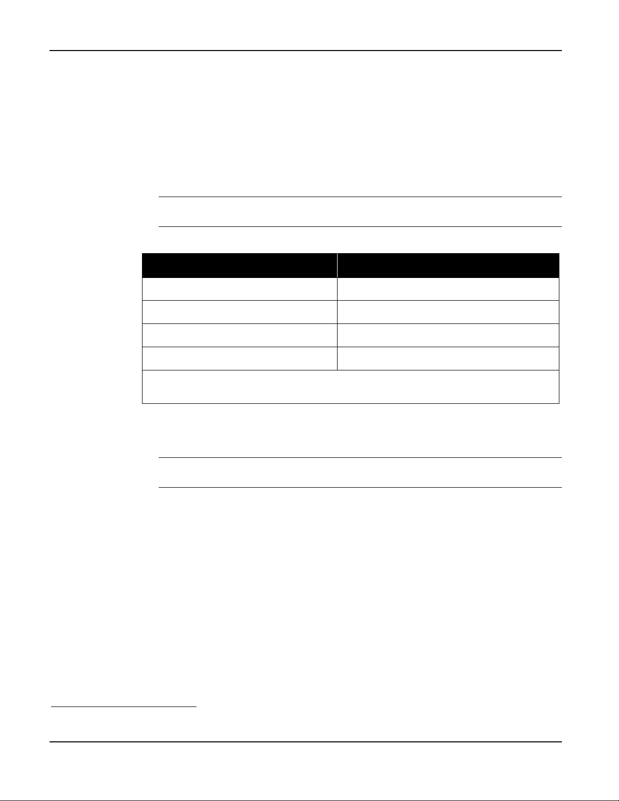
The maximum distance to space BlueTOAD PoE or Cellular is a function of the road type:
Road Type Maximum Spacing, miles
Highway 4 to 5
Arterial (no traffic lights) 2 to 2 ½
Arterial (with traffic lights) 1 to 1 ½
Dense urban area* 1
* Note: The number of intersections, traffic signals, or exit ramps can affect the speed/travel time;
thus, you should keep them to a minimum.
In an Origin/Destination (O/D) deployment, you must install BlueTOAD detectors before
the destination as well as after. The number of additional BlueTOAD detectors necessary is
then based on driver options.
Example: If a driver could turn either left or right at T intersection, you must install
a BlueTOAD in each of the two possible directions of travel.
Pre-Installation Testing
The steps that follow give instructions to test BlueTOAD Spectra detectors before they are installed in the
field:
To test a Spectra Ethernet PoE or a Spectra Ethernet Cellular PoE, go to Step 4.
To test a Spectra Solar Cellular, go to Step 5.
4. To test a Spectra PoE detector:
a. Connect the Ethernet cable to power ON the detector.
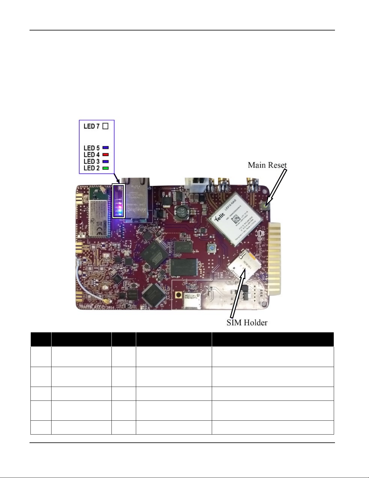
b. In the presence of Bluetooth signals, open the enclosure and confirm that the LEDs on the
PCB3 are operating correctly.
c. Go to Step 6.
3
The PCB with its LEDs is the same in all three types of BlueTOAD Spectra detectors. Correct operation of the LEDs is shown
in the photograph and table on Page 2-5.
TrafficCast Quick Start—BlueTOAD Spectra and Spectra RSU
2-4 Revision 02 May 2019
Page 15
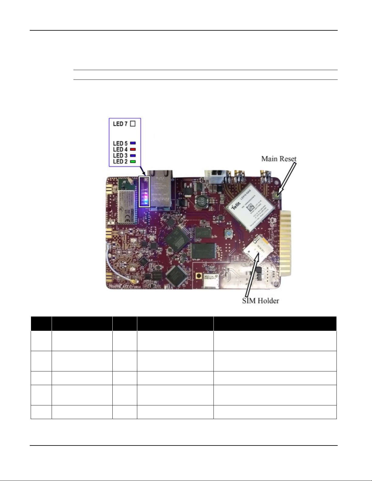
5. To test a Spectra Solar Cellular detector:
a. Open the Spectra enclosure.
b. Connect the Battery to the Charge Controller with the Quick Connect from the Battery.
Note: The Quick Connect is illustrated on Page 2-16 (but do NOT attach the Battery yet).
c. On the BlueTOAD card (PCB), LED 7 should start flashing.
d. In the presence of Bluetooth signals, confirm the LEDs operate as shown below.
e. Go to Step 6.
LEDs inside a BlueTOAD Spectra
BlueTOAD Spectra Deployment
LED Function Color @ Initial Startup @ Normal State (takes up to 5 minutes)
7 Network Connection
5 Bluetooth Detection
4 Diagnostics Reporting Red OFF Blinks – 1 x per 3 sec.
3 Connection Strength Blue OFF
2 Kernel Diagnostics Green OFF Blinks – 1 x per 3 sec.
Multicolor
Multicolor
White – Searching for Cell
Green – Searching for GPS
Blue – Discoverable
Purple – Non-Discoverable
OFF – Cell and GPS established
Blinks upon detection
Flash blue if > - 90 dbm (good)
Solid blue if < - 90 dbm (poor)
TrafficCast Quick Start—BlueTOAD Spectra and Spectra RSU
Revision 02 May 2019 2-5
Page 16

BlueTOAD Spectra Deployment
Field Installation
BlueTOAD Spectra
Ethernet
PoE
Ethernet
Cellular PoE
Solar
Cellular
6. After you have tested the LEDs for your Spectra detector in the presence of Bluetooth signals:
a. Call the TrafficCast Customer Support Number, (608) 713-9299; report the BlueTOAD
device number, say that the detector has been powered ON, and that the LEDs are normal.
b. Wait for the TrafficCast representative to verify the network is seeing data from the detector.
c. After confirmation from TrafficCast, remove the Ethernet cable to power OFF4 the detector;
now the Spectra detector is ready for installation in the field.
Field Installation
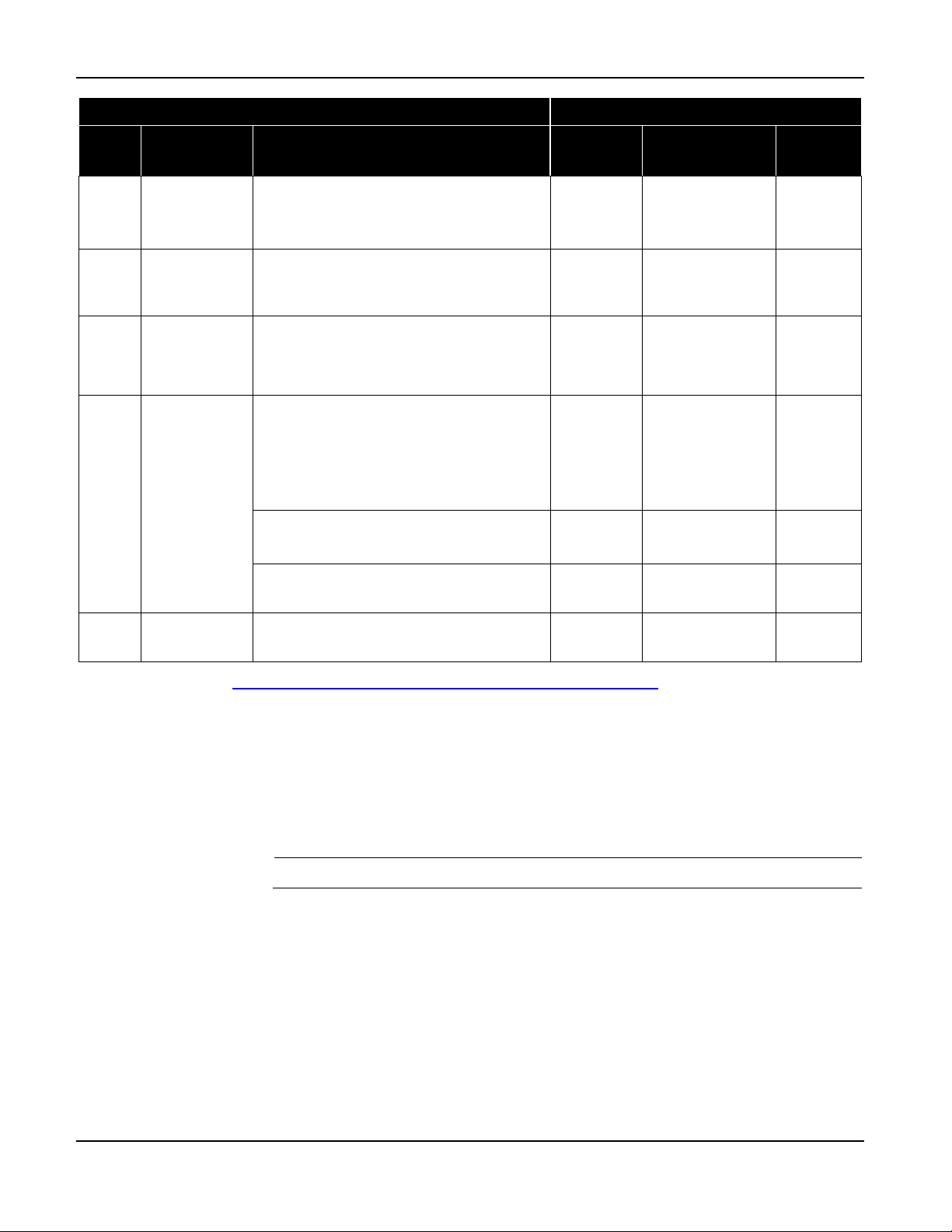
The table below summarizes the steps to install each of the three types of BlueTOAD Spectra detector in
the field. The two sections that follow give detailed instructions for the installation of the main types of
BlueTOAD Spectra detectors:
• Go to Step 7 to install a Spectra Ethernet PoE or a Spectra Ethernet Cellular PoE—connected to a
roadside traffic signal cabinet and powered over Ethernet through a CAT-5 Cable.
• Go to Step 9 to install a stand-alone Spectra Solar Cellular, powered with a solar-charged battery.
Step Procedure Instructions
1
2
3
Select a
Lamp or
Signal Pole
on which to
mount the
Spectra
Enclosure
Mount
Spectra
enclosure
Mount Solar
Panel
Align Spectra
enclosure
Make sure
there is a clear
line-of-sight
from the
Spectra
antennas to
the target road
segment
12 to 14 feet
above the
roadbed
Mount above
the Spectra
enclosure,
facing true
south
Roadside Installation: align
parallel to the roadway
Center Median Installation: align
perpendicular to the roadway
Pole should be near
the roadside traffic
signal cabinet (for easy
conduit access)
NOT necessary for the
pole to be near a
cabinet — this is a
stand-alone unit
Attach with 1 Cable
Band thru its bracket
Attach with 2 Cable
Bands thru 2 brackets
Attach with 2 Cable
Bands thru 2 brackets
Connect Solar Panel
Power Cable to the
Spectra enclosure
X X
X
X X
X
X
X X X
X X X
4
For a Solar Spectra, to power OFF, unplug the Quick Connect between the Battery and the Charge Controller. Remove the
Battery and keep it separate until the Spectra enclosure is installed on a pole. Because of the heavy battery, it is easier to install the
enclosure first and then install the Battery after the enclosure is mounted on a pole. The total weight is 40 pounds.
2-6 Revision 02 May 2019
TrafficCast Quick Start—BlueTOAD Spectra and Spectra RSU
Page 17
Field Installation
BlueTOAD Spectra
Step Procedure Instructions
Ethernet
PoE
Ethernet
Cellular PoE
Solar
Cellular
BlueTOAD Spectra Deployment
4
5
6
7
Set Solar
Panel Angle
Open the
enclosure
Install the
Battery
Connect
Cables
Close the
enclosure
Set the angle per the location. Click the
link* at the end of this table for
instructions.
This is necessary to install the Battery
and make sure the LEDs are operating
correctly
Attach the Quick Connect to the Battery
Install the Battery vertically
Secure the Battery with the tie downs
Pull the main CAT-5 PoE Cable through
the roadside conduit
Connect CAT-5 to the PoE Splitter
(Spectra) and the PoE Injector (cabinet)
Connect AC power to PoE Injector
Connect PoE Injector to network
Ethernet Switch
Connect the Battery to the Charge
Controller—LED 7 starts to flash
X
X
X
X X
X
X
X
* Solar calculator link: http://solarelectricityhandbook.com/solar-angle-calculator.html
Field Installation for Ethernet PoE Detectors
7. Installation guidelines for Spectra Ethernet PoE and Spectra Ethernet Cellular PoE enclosures:
a. Mounting Structure—a lamp or signal pole that is:
Near the roadside traffic signal cabinet
Note: The mounting pole should be near the cabinet for easy conduit access.
Has a mounting location with a clear line-of-sight from the Spectra antennas to the
target road segment
b. Mounting Height—12 to 14 feet above the roadbed
TrafficCast Quick Start—BlueTOAD Spectra and Spectra RSU
Revision 02 May 2019 2-7
Page 18
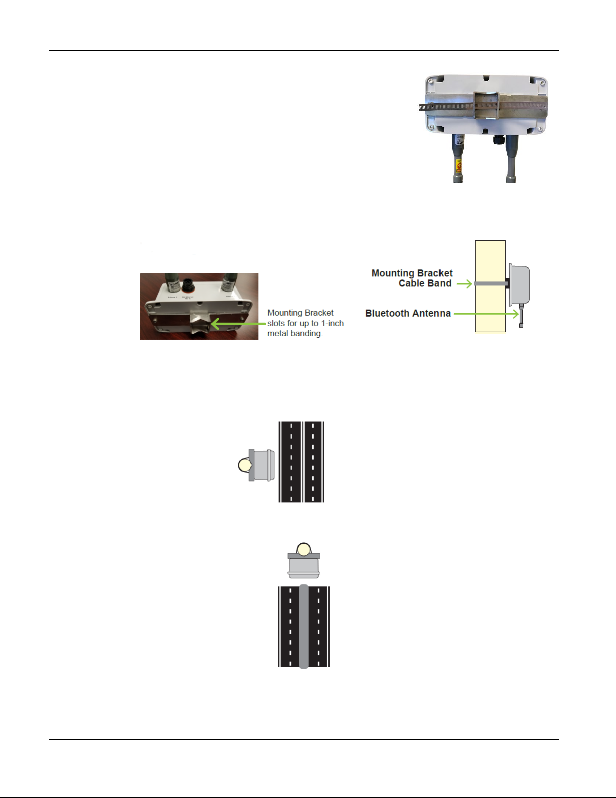
BlueTOAD Spectra Deployment
c. Mount the Enclosure to the Pole
i. Insert the Cable Band through the slot in the
Mounting Bracket.
ii. Wrap the Cable Band around the pole.
iii. Use a drill to tighten the Cable Band with
a 5/16” nut driver bit or equivalent.
d. Align the Enclosure as shown below:
For Roadside Installation, align the front cover of the enclosure
Parallel to the roadway.
For Center Median Installation, align the front cover of the enclosure
Perpendicular to the roadway.
TrafficCast Quick Start—BlueTOAD Spectra and Spectra RSU
2-8 Revision 02 May 2019
Page 19
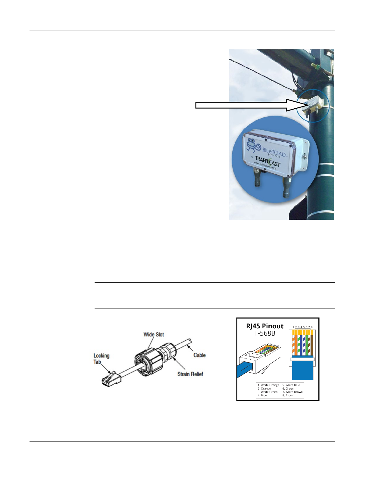
BlueTOAD Spectra Deployment
This is a Roadside Installation.
The front cover of the Spectra
PoE enclosure is aligned
Parallel to the roadway.
8. Guidelines to route and connect the cables:
a. Traffic Closure—Close traffic lanes as necessary to pull cable.
b. CAT-5 Ethernet Cable—Pull the main CAT-5 Cable through the roadside conduit.
c. Run the cable from the roadside cabinet to the BlueTOAD enclosure on the pole.
d. Pass the cable through the Liquid-Tight Cable Gland.
Note: You will have to remove the Strain Relief on the cable to pass it through the
Cable Gland. However, you can slide the Strain Relief away from the RJ-45
connector without cutting the Strain Relief. Use the RJ-45 Pinout given below.
TrafficCast Quick Start—BlueTOAD Spectra and Spectra RSU
Revision 02 May 2019 2-9
Page 20
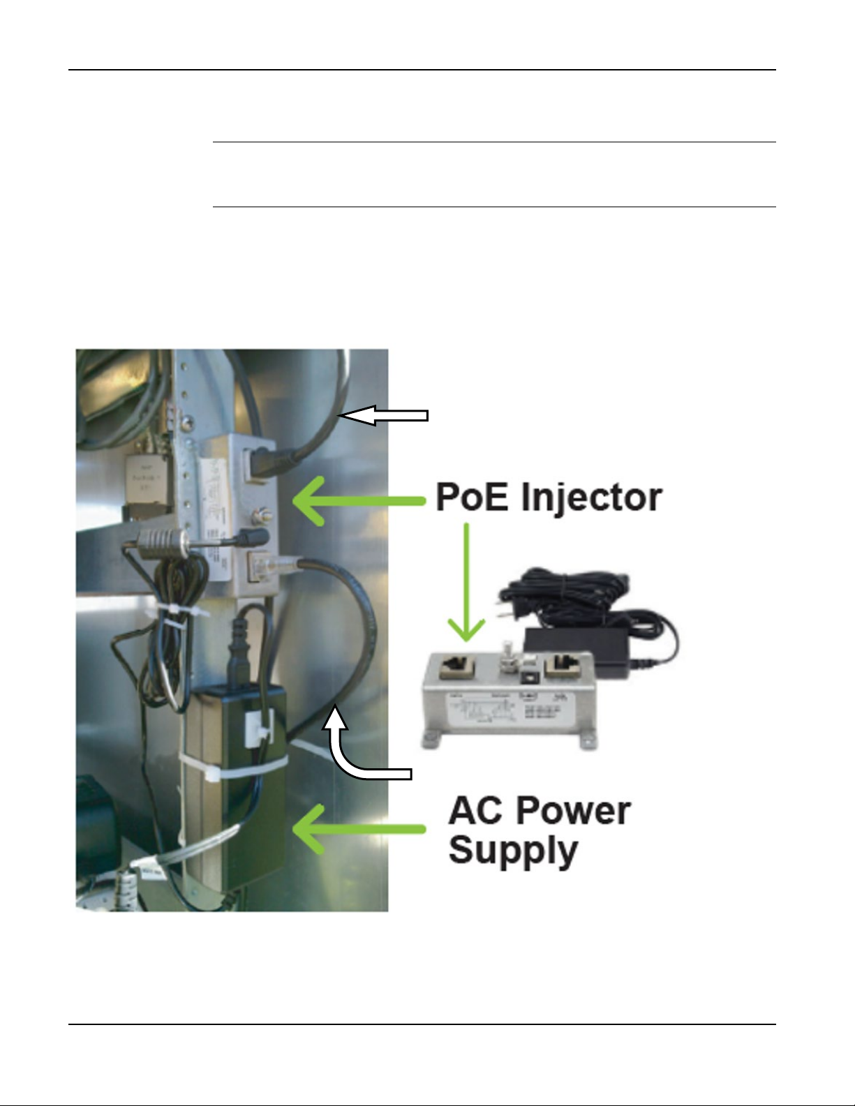
BlueTOAD Spectra Deployment
Main CAT-5 Ethernet Cable
e. Install the PoE Injector in the roadside cabinet:
i. Secure the PoE injector onto a flat surface inside the roadside cabinet.
Note: The PoE Injector has two RJ-45 ports:
• Data—connects to the network Ethernet switch, router or hub
• Data and Power—connects to the PCB of the Spectra, i.e. to the PoE Splitter
ii. Connect the ground wire.
iii. Connect the Main CAT-5 Ethernet Cable to the PoE Injector.
iv. Connect an Ethernet cable from the PoE Injector to the cabinet LAN/WAN Ethernet
Network Switch or Router. *
Ethernet Cable to Ethernet
Network Switch or Router *
* Note: For an Ethernet Cellular PoE detector, do NOT connect the PoE Injector to a LAN/WAN
Switch/Router or to a Traffic Controller; this type of BlueTOAD detector bypasses the servers-firewall of
the Agency and communicates directly with TrafficCast National Servers over the cellular network.
2-10 Revision 02 May 2019
TrafficCast Quick Start—BlueTOAD Spectra and Spectra RSU
Page 21
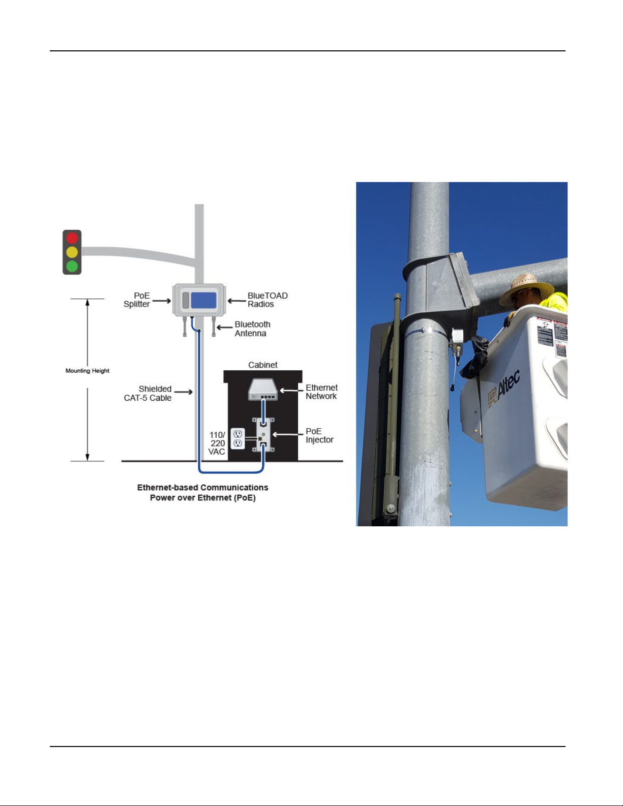
v. Connect the Ethernet Network Switch to the Traffic Controller.
12 to14 Feet
vi. Connect the AC Power Supply to the PoE Injector.
vii. Plug the 110 VAC cord into an AC power outlet receptacle.
This is the completed installation:
BlueTOAD Spectra Deployment
TrafficCast Quick Start—BlueTOAD Spectra and Spectra RSU
Revision 02 May 2019 2-11
Page 22
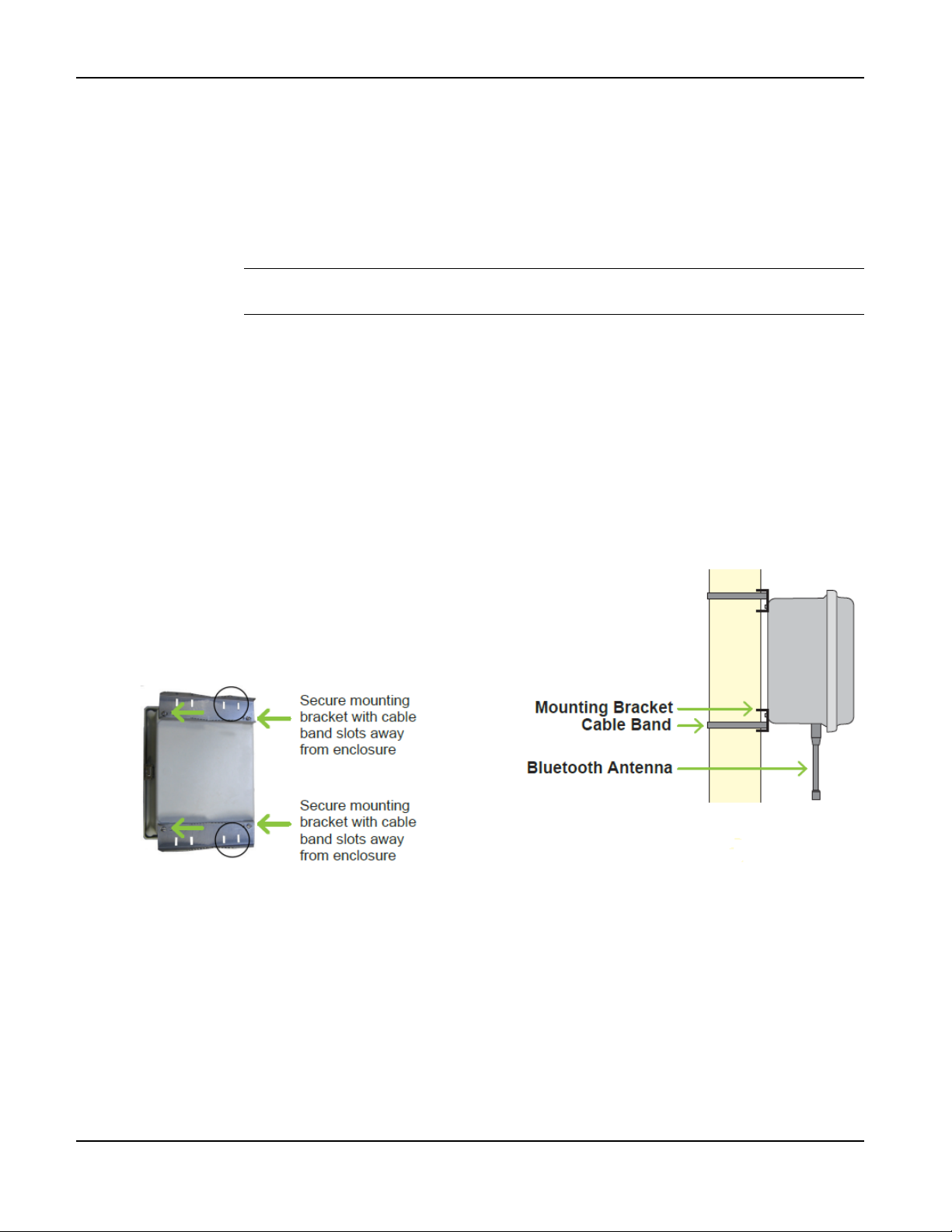
BlueTOAD Spectra Deployment
Field Installation for BlueTOAD Spectra Solar Cellular Detectors
9. Installation guidelines for Spectra Solar Cellular enclosures:
a. Mounting Structure—a lamp or signal pole that has a mounting location with a clear line-of-
sight from the Spectra antennas to the target road segment.
b. Mounting Height—12 to 14 feet above the roadbed.
c. Mount the Spectra Enclosure to the Pole
Note: Make sure that the Battery is outside of the enclosure. You will install the
Battery after the enclosure is mounted on the pole.
Supplied with a Solar Cellular are:
2 Mounting Brackets with screws to attach them to the detector enclosure
2 Cable Bands designed to fasten the enclosure to poles up to 14 inches in diameter
i. As shown below, secure the Mounting Brackets to the enclosure with the Cable Band
slots facing away from the enclosure.
ii. Insert the Cable Bands through the slots in the Mounting Brackets.
iii. Wrap the Cable Bands around the pole.
iv. Use a drill to tighten the Cable Bands with a 5/16” nut driver bit or equivalent.
TrafficCast Quick Start—BlueTOAD Spectra and Spectra RSU
2-12 Revision 02 May 2019
Page 23
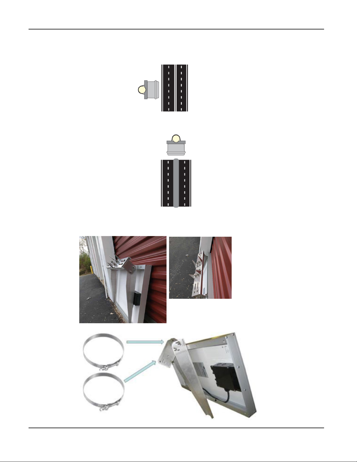
d. Align the Enclosure—as shown below:
For Roadside Installation, align the front cover of the enclosure
Parallel to the roadway.
For Center Median Installation, align the front cover of the enclosure
Perpendicular to the roadway.
BlueTOAD Spectra Deployment
e. Install the Solar Panel
i. Attach the Mounting Bracket to the Solar Panel.
TrafficCast Quick Start—BlueTOAD Spectra and Spectra RSU
Revision 02 May 2019 2-13
Page 24
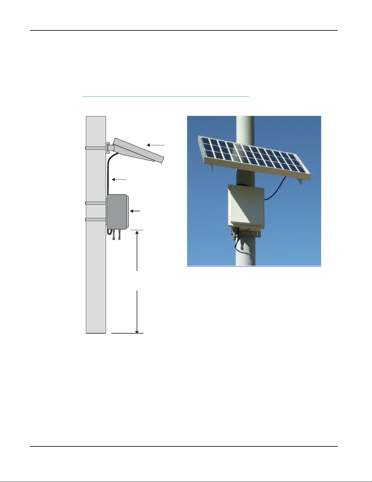
BlueTOAD Spectra Deployment
12-14
Feet
BlueTOAD
Cabinet Door
Solar Panel
Power Cable
Solar Panel
- Installed for best
direction of sun.
STREET
Metal
Banding
ii. Mount the Solar Panel above the BlueTOAD enclosure.
iii. Mount the Solar Panel facing true south.
iv. Use a drill to tighten the Cable Band with a 5/16” nut driver bit or equivalent.
v. Go to this website and enter data in a Solar Calculator to set the Solar Panel to the
optimum angle for your location:
http://solarelectricityhandbook.com/solar-angle-calculator.html
TrafficCast Quick Start—BlueTOAD Spectra and Spectra RSU
2-14 Revision 02 May 2019
Page 25
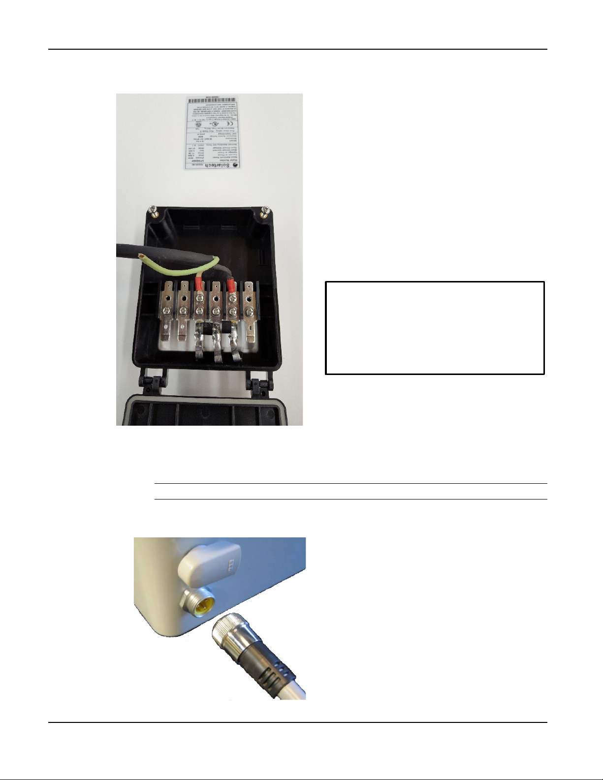
BlueTOAD Spectra Deployment
Important: After connecting the cable,
voltage to the cable
f. As shown below, connect the Solar Panel Power Cable to the Junction Box on the
Solar Panel:
use a multi-meter to make sure that:
• The cable is correctly
connected to the junction box
• The solar panel is outputting
g. Connect the Solar Panel Power Cable to the Spectra enclosure:
i. Insert the cable plug into its connector on the enclosure.
Note: The plug is keyed—you can only insert it in the correct position.
ii. Hand tighten the connector nut.
TrafficCast Quick Start—BlueTOAD Spectra and Spectra RSU
Revision 02 May 2019 2-15
Page 26
BlueTOAD Spectra Deployment
Plug in the Quick Connect cable here to Connect
Positive (red) Battery Terminal
Quick Connect cable
Negative
Battery Terminal
BlueTOAD
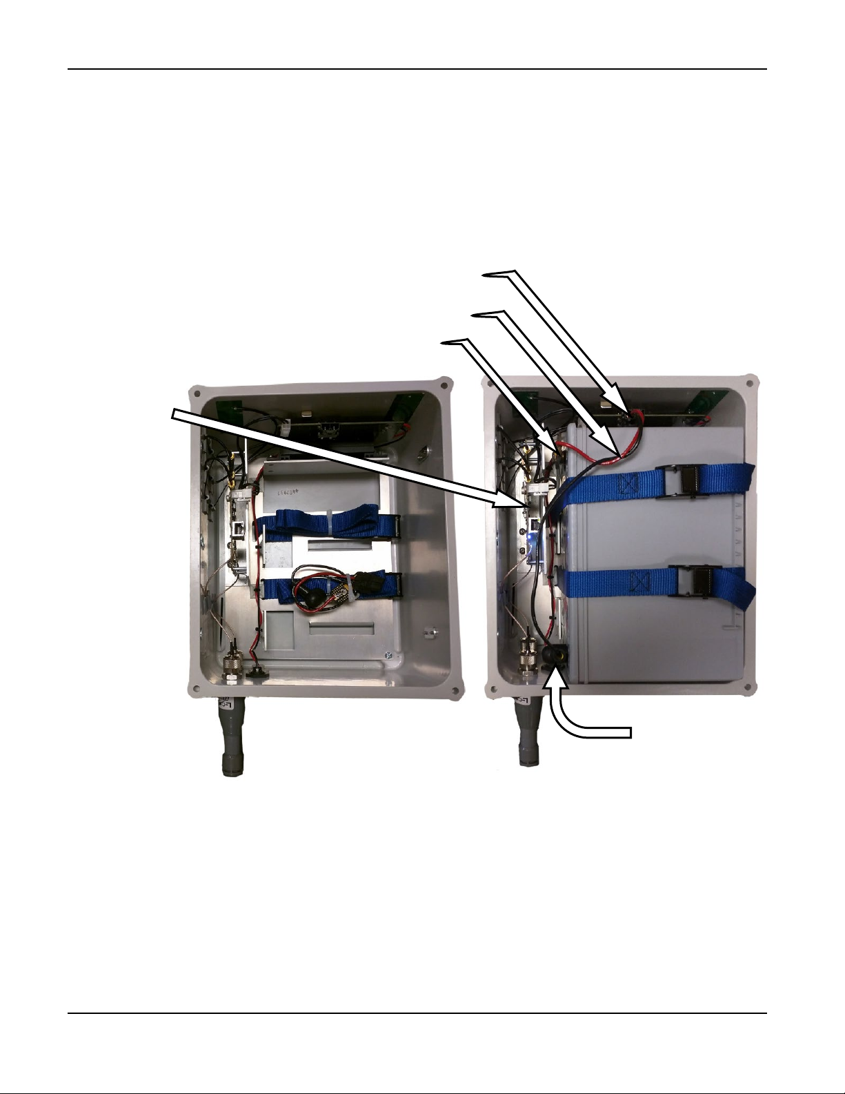
h. Install the Battery (cables, connectors, and tie-downs are supplied)
i. Open the Spectra Solar enclosure.
ii. Attach the Quick Connect to the Battery—with the self-healing fuse connected to the
positive (red) terminal.
iii. Mount the Battery vertically with the positive terminal on the top.
iv. Secure the Battery with the tie-downs.
the Battery to the Charge Controller (Step h.)
Card (PCB)
with the
LEDs
Before Battery Installation After Battery Installation
2-16 Revision 02 May 2019
TrafficCast Quick Start—BlueTOAD Spectra and Spectra RSU
Page 27
BlueTOAD Spectra Deployment
i. Connect the Battery and Power ON the Detector.
i. Refer to the photograph on the previous page to connect the Battery to the Charge
Controller with the Quick Connect cable.
ii. On the BlueTOAD Card (PCB), LED 7 should start flashing.
iii. In the presence of Bluetooth signals, confirm LEDs on the PCB operate as shown below.
iv. Close and fasten the Solar Cellular Enclosure.
j. Go to Step 11, Confirm Network Connectivity and Data Collection.
LEDs inside a BlueTOAD Spectra
LED Function Color @ Initial Startup @ Normal State (takes up to 5 minutes)
7 Network Connection
5 Bluetooth Detection
4 Diagnostics Reporting Red OFF Blinks – 1 x per 3 sec.
3 Connection Strength Blue OFF
2 Kernel Diagnostics Green OFF Blinks – 1 x per 3 sec.
TrafficCast Quick Start—BlueTOAD Spectra and Spectra RSU
Revision 02 May 2019 2-17
Multicolor
Multicolor
White – Searching for Cell
Green – Searching for GPS
Blue – Discoverable
Purple – Non-Discoverable
OFF – Cell and GPS established
Blinks upon detection
Flash blue if > - 90 dbm (good)
Solid blue if < - 90 dbm (poor)
Page 28
BlueTOAD Spectra Deployment
Test after you Mount a BlueTOAD Spectra PoE Detector to a Pole
10. Go to the procedure below (a or b) that is related to your Spectra PoE type of detector.
a. For a Spectra Ethernet PoE
i. Plug the main CAT-5 cable from the PoE Injector (in the cabinet) into the PoE Splitter
(in the Spectra enclosure), as shown in the drawing on Page 2-11.
ii. Spectra detector should power ON.
iii. Confirm all LEDs (on cabinet Ethernet switch, PoE Power supply or Ethernet port
connections) are normal.
iv. Ensure Network and Port configuration:
v. Go to Step 11, Confirm Network Connectivity and Data Collection.
b. For a Spectra Ethernet Cellular PoE:
i. Plug the main CAT-5 cable from the PoE Injector (in the cabinet) into the PoE Splitter
(in the Spectra enclosure), as shown in the drawing on Page 2-11.
ii. The Spectra detector should power ON.
iii. Confirm LED (on cabinet PoE Power supply) is normal.
Confirm Network Connectivity and Data Collection
11. Now that you have tested the LEDs, make sure that data is being received by the TrafficCast
National Servers:
a. Using a laptop, iPad or Android tablet with access to the Internet, launch Google Chrome or
Microsoft Edge web browser.
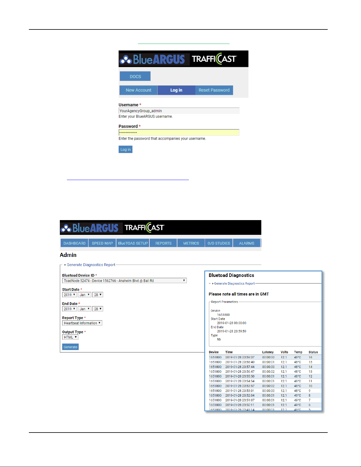
b. Log in to BlueARGUS (TrafficCast will provide login Username and Password before
installation).
TrafficCast Quick Start—BlueTOAD Spectra and Spectra RSU
2-18 Revision 02 May 2019
Page 29
BlueTOAD Spectra Deployment
c. BlueARGUS Login page: https://bluetoad.trafficcast.com/
d. Enter Diagnostics URL to test that data collection is active and generate a diagnostics report:
https://bluetoad.trafficcast.com/diagnostics
e. Select BlueTOAD Device ID from the dropdown list.
f. From Report Type dropdown list, select Heartbeat Information.
g. From Output Type dropdown list, select HTML.
h. Select Generate to open the
diagnostics report. BlueTOAD
Spectra should start to collect
data within 2-5 minutes after
you enable power connections.
TrafficCast Quick Start—BlueTOAD Spectra and Spectra RSU
Revision 02 May 2019 2-19
Page 30

BlueTOAD Spectra Deployment
Troubleshooting
12. Troubleshooting BlueTOAD Spectra Connectivity
After the detector has started detecting Bluetooth signals, communicated the device ID number, and
the LEDs are normal:
a. Call the TrafficCast Customer Support Number, (608) 713-9299.
b. Confirm from TrafficCast that the network is transmitting the data from this detector.
c. Possible issues include:
Network Port settings are incorrect – confirm the settings with the Agency IT department
(as above)
Ethernet switch port not active or communicating
BlueTOAD Spectra not powered – check PoE connections
Troubleshooting of Server Errors
Error Message Possible Issues
NTP Server Error
BlueTOAD Server Error
NTP Server Error
– or –
BlueTOAD Server Error
Port 123 is not open
NTP server address is not correct
Port 8010 is not open
TCP protocol not allowed
BlueTOAD server address is not correct
IP address is not correct
Gateway address is not correct
DNS address is not correct
Port 53 for DNS is not open
DSN UDP protocol not allowed
EMAC address is blocked
TrafficCast Quick Start—BlueTOAD Spectra and Spectra RSU
2-20 Revision 02 May 2019
Page 31

BlueTOAD Spectra Deployment
Record Keeping
13. In the pre-installation process, TrafficCast adds each installed BlueTOAD detector to a list of
detector locations within the BlueARGUS web-based reporting application (for your records, also
keep a list of device ID, location, and installation date for each detector).
Note: For a helpful workbook to keep a record of information for each detector, go to
https://trafficcast.zendesk.com/hc/en-us/articles/360015177732-Preprogramminginstallation-cheat-sheet
In the middle left of the page, select BlueTOAD Programming Cheat Sheet.xlsx
At the bottom left of the Excel page, notice the Pre Installation Sheet and
Field Installation Check List tabs.
Customer Support Number: (608) 713-9299
TrafficCast Support Website: https://trafficcast.zendesk.com (TrafficCast will schedule an
installation appointment.)
Data and Device Management via BlueARGUS
14. TrafficCast Support will set up and configure Agency access to BlueARGUS data collection and
management system.
You can monitor each BlueTOAD detector using the web-based BlueARGUS software.
You will be given login credentials (Username and Password) before field installation, based
on your predetermined Role (Administrator or User) when the Account was initially set up.
BlueARGUS Website: https://bluetoad.trafficcast.com/
On-Going Operations / On-Going Customer Support
15. Each Connected Vehicle system deployed will have access to the full suite of support resources
available through the TrafficCast and BlueARGUS system management software:
BlueARGUS On-Going Operations Website: https://bluetoad.trafficcast.com
TrafficCast Support Website: https://trafficcast.zendesk.com
TrafficCast Support Number: 608-713-9299
TrafficCast Quick Start—BlueTOAD Spectra and Spectra RSU
Revision 02 May 2019 2-21
Page 32

BlueTOAD Spectra Deployment
For your notes:
TrafficCast Quick Start—BlueTOAD Spectra and Spectra RSU
2-22 Revision 02 May 2019
Page 33

3. BlueTOAD Spectra RSU Deployment
Purpose
The procedures in this chapter tell you what to do to deploy a BlueTOAD Spectra RSU. We assume you are
familiar with the BlueTOAD Spectra RSU, supporting equipment, and the associated software listed below.
Supporting Equipment
• Windows PC and Ethernet Cables
• BlueTOAD Spectra RSU Configuration Utility (Microsoft Windows 10 App)
• WinSCP or equivalent File Transfer Application
• PuTTY or equivalent SSH Client
• TrafficCast BlueTOAD Spectra RSU
• LCOM PoE Injector
• Traffic Controller with Power Cable or Similar ATC Controller5
• 7-Zip Archiving Utility
• Advanced IP Scanner (Optional)
• Work area with adequate GPS reception
Procedures
The procedures that follow tell you how to deploy and test a BlueTOAD Spectra RSU Connected Vehicle
(CV) and Dedicated Short Range Communications (DSRC) data collection and management system.
Note: After notice to proceed is approved, TrafficCast and key collaborative team personnel will
work with your Agency to create a formal deployment, implementation and operations plan
document for your BlueTOAD Spectra RSU system.
FCC License: Each DSRC-based RSU requires an FCC License to operate within a specific
transportation agency jurisdiction. Only transportation agencies or transportation authorities can
apply for and operate a 5.9 GHz DSRC spectrum-based radio broadcast system.
TrafficCast can provide support for your Agency to acquire an FCC Regional License to manage
and operate the DSRC Network. We can also help you apply for required single FCC filings per
RSU and RSU location. The TrafficCast RSU has been accepted by the FCC for deployment in the
past, and we anticipate a successful outcome for your project.
5
Refer to the table of Compatible Traffic Controllers on Page 1-2.
TrafficCast Quick Start—BlueTOAD Spectra and RSU
Revision 02 May 2019 3-1
Page 34

BlueTOAD Spectra RSU Deployment
Layout Guidelines
1. After you select the target road segment for CV and DSRC data collection and management, use the
guidelines that follow to determine how many TrafficCast BlueTOAD Spectra Roadside Units
(RSUs) are necessary for your project.
The RSU has an effective DSRC detection range of up to approximately 3,000 feet radius
from the antennas (with direct line-of-sight).
You can install an RSU at each signalized intersection, mid-block or highway location that
has an appropriate 120 VAC power source.
The minimum recommended (but not limited) distance to space the Spectra RSU is every
0.25 mile; this is because of the minimum recommended distance to space the BlueTOAD
detector part of the RSU.
Note: Power Control lets you reduce the detection zone to minimize overlap. Thus,
with Power Control, the minimum spacing could be less than 0.25 mile.
Pre-Install Evaluation and Setup
2. Before you install an RSU, make sure things are ready at the installation sites:
a. Location – Prepare a sight survey of all intersection locations that have been selected to
deploy RSUs.
Identify power sources available in the traffic cabinets.
Make sure you have all the necessary parts for the system. Refer to the table on
Page 1-2 for a list of the items included with an RSU.
Are the Traffic Controllers in the traffic cabinets compatible with the RSU?
Refer to the table of Compatible Traffic Controllers on Page 1-2.
b. Traffic Network – Evaluate the existing network.
Fiber and/or Ethernet based?
Confirm that the network settings (for example, IP address, gateway, subnet mask,
and DNS) are correctly set and that all ports (69, 123, 8010, 10001) are open and set
for outbound data traffic.
Important: Confirm all necessary inbound/outbound network ports have
been set up.
What are the IP addresses assigned to the Traffic Controller and to the RSU?
Note: If there is a Processor (optional), it also has an IP address.
c. MAP File Creation – For each intersection, create a MAP file with Signal, Phase and Timing
(SPaT) information. For instructions, refer to Appendix 4, How to Create an RSU MAP File.
d. Fill out the Spectra RSU Site Requirements form on Page 6-3.
e. Notify the TrafficCast support team to schedule a date for remote support for installation.
TrafficCast Quick Start—BlueTOAD Spectra and Spectra RSU
3-2 Revision 02 May 2019
Page 35
BlueTOAD Spectra RSU Deployment
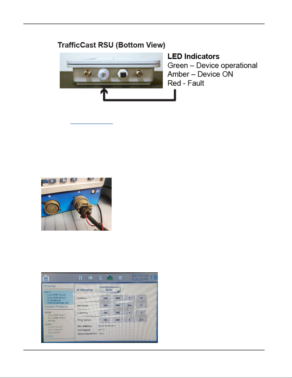
f. Power ON the RSU and confirm all LEDs are normal after the unit initializes:
How to Set Up the Traffic Controller Before Field Deployment
This example uses an Econolite traffic controller, model Cobalt Advanced Traffic Controller (ATC).
However, you can use ATC controllers (preferred) from other manufacturers that have Ethernet and IP
interfaces. Refer to the table on Page 1-2 for Compatible Traffic Controllers. Also, you can consult
TrafficCast Support for models of traffic controllers supported; these include McCain (software Version
1.10.2.6705-2018-03-23), Siemens (software Version 3.59+), Trafficware (software Version 76.15N+) and
Intelight (Maxtime CV).
1. Attach the Traffic Controller “A” power cable to the “A” connector of the controller.
2. Plug the “A” power cable into an AC power source. The controller should power ON.
3. Using the example default IP address of a stock BlueTOAD Spectra RSU, 192.168.1.76, navigate to
the Ethernet communications page of the controller.
4. Set the controller IP address to 192.168.1.32 and Netmask to 255.255.255.0. Set the Ping Server to
the IP address of the RSU.
TrafficCast Quick Start—BlueTOAD Spectra and Spectra RSU
Revision 02 May 2019 3-3
Page 36
BlueTOAD Spectra RSU Deployment
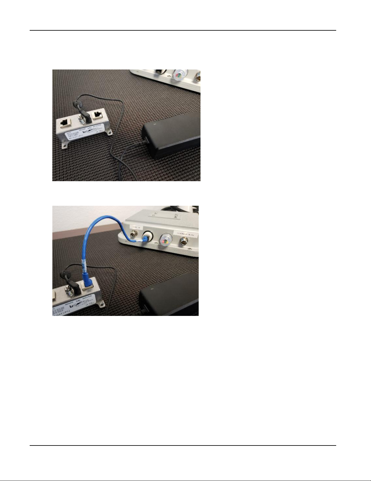
5. Plug the AC power cable of the POE injector AC adapter to an AC power source.
6. Plug the AC adapter output power cable into the POE injector. The AC adapter LED indicator
should light up with power.
7. Connect the RSU to the Data+PWR port of the POE Injector with an Ethernet cable. The RSU
Power LED indicator should light up with power.
TrafficCast Quick Start—BlueTOAD Spectra and Spectra RSU
3-4 Revision 02 May 2019
Page 37
BlueTOAD Spectra RSU Deployment
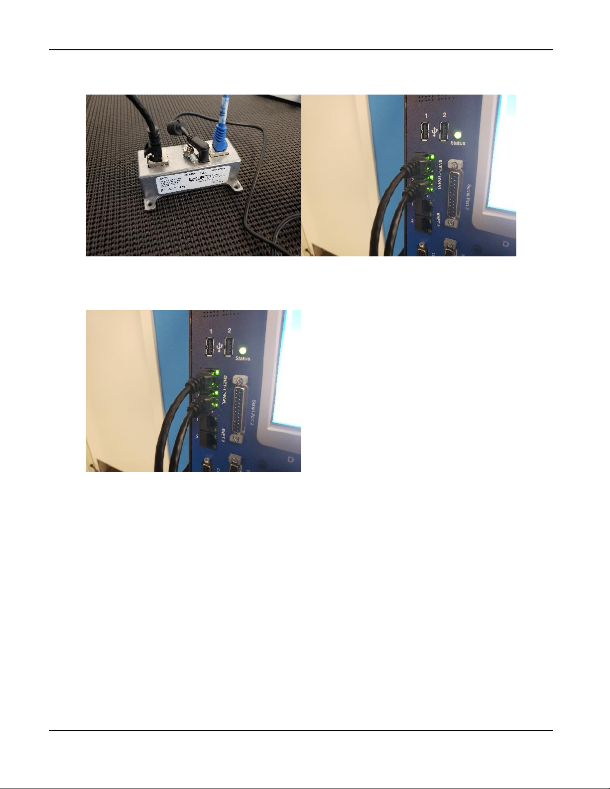
8. Connect the POE Injector Data port to Port 1 of ENET-1 (WAN) of the controller with an
Ethernet cable.
9. Connect the computer to Port 2 of ENET-1 (WAN) of the controller with an Ethernet cable.
10. Set the computer IP address to match the subnet of the RSU and controller—for example,
192.168.1.100.
TrafficCast Quick Start—BlueTOAD Spectra and Spectra RSU
Revision 02 May 2019 3-5
Page 38
BlueTOAD Spectra RSU Deployment
Factory “Stock” RSU Configuration Procedure—using the BlueTOAD RSU Configuration Utility
Note: For a manual procedure, refer to Appendix 5—How to Manually Configure a BlueTOAD Spectra RSU.
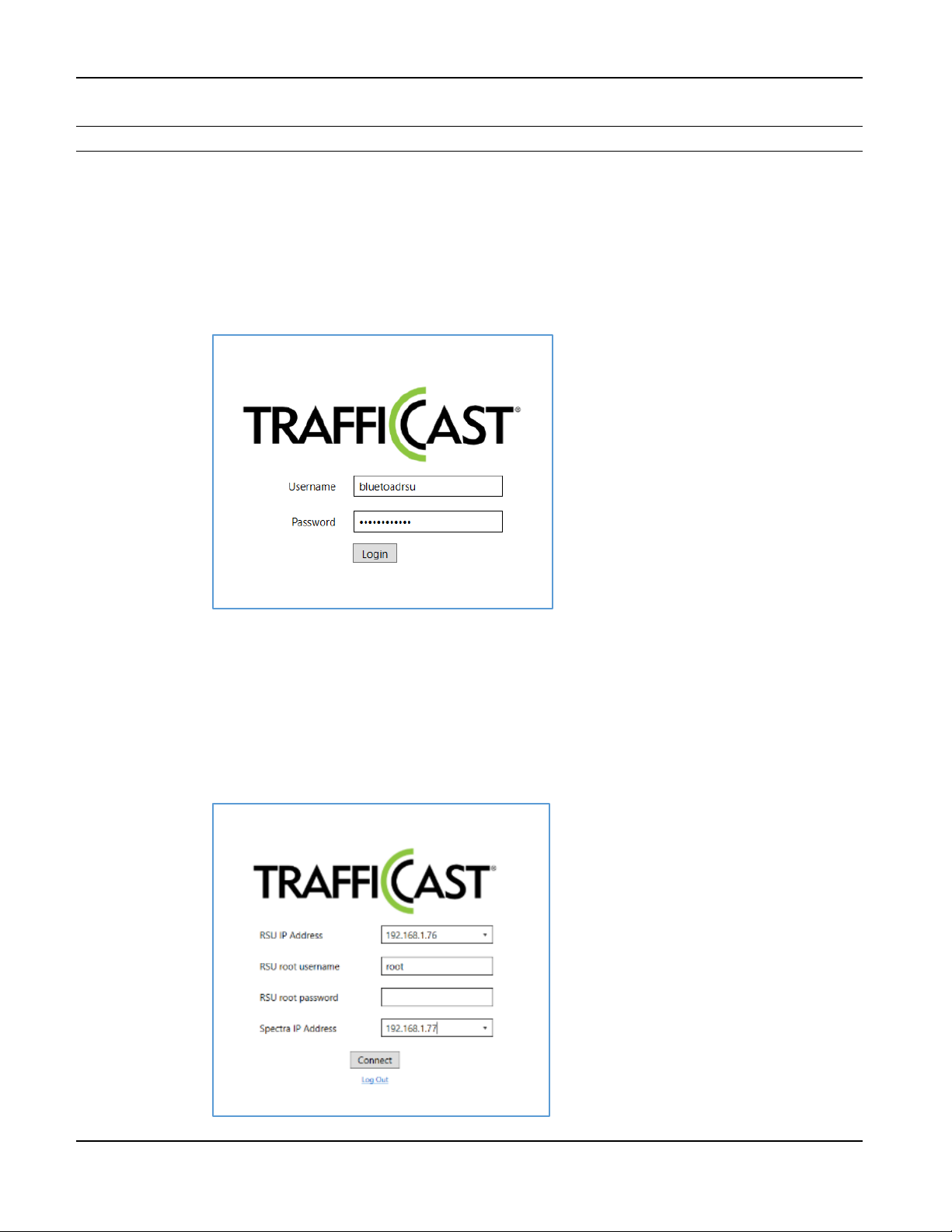
1. Log into BlueTOAD Spectra RSU Configuration Utility.
a. Enter Default Utility Login information (Available Login roles include Admin, Tech1 and
Tech2):
i. Username: bluetoadrsu
ii. Password: amb3rEarth15
b. Select Login.
c. Enter Default RSU Login information:
i. RSU IP Address: 192.168.1.76
ii. RSU Root Username: root
iii. RSU Root Password: heavyduty@19!
iv. Spectra IP Address: 192.168.1.77
d. Select Connect to log into the BlueTOAD RSU Configuration Utility main menu.
TrafficCast Quick Start—BlueTOAD Spectra and Spectra RSU
3-6 Revision 02 May 2019
Page 39
BlueTOAD Spectra RSU Deployment
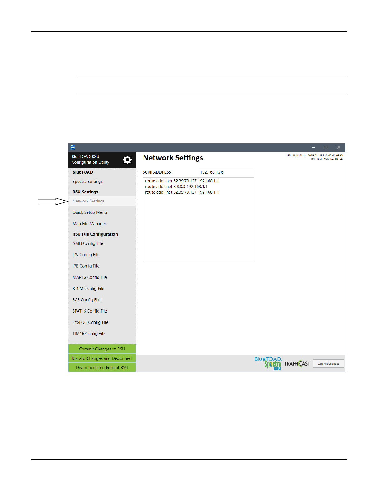
2. Change the IP Address of the RSU:
a. Under the RSU Settings menu, select the Network Settings tab.
b. Change these settings and keep a record of the changes:
Important: Make sure that you keep a record of the new settings. If you do not know the
RSU IP address, you CANNOT log back into the RSU!
i. Change NETMASK: (Default: 24)
ii. Change SCO IP ADDRESS: (Default: 192.168.1.76)
c. On the BlueTOAD RSU Configuration Utility taskbar, select Commit Changes to submit
these changes to the RSU.
TrafficCast Quick Start—BlueTOAD Spectra and Spectra RSU
Revision 02 May 2019 3-7
Page 40
BlueTOAD Spectra RSU Deployment
Command:
route add
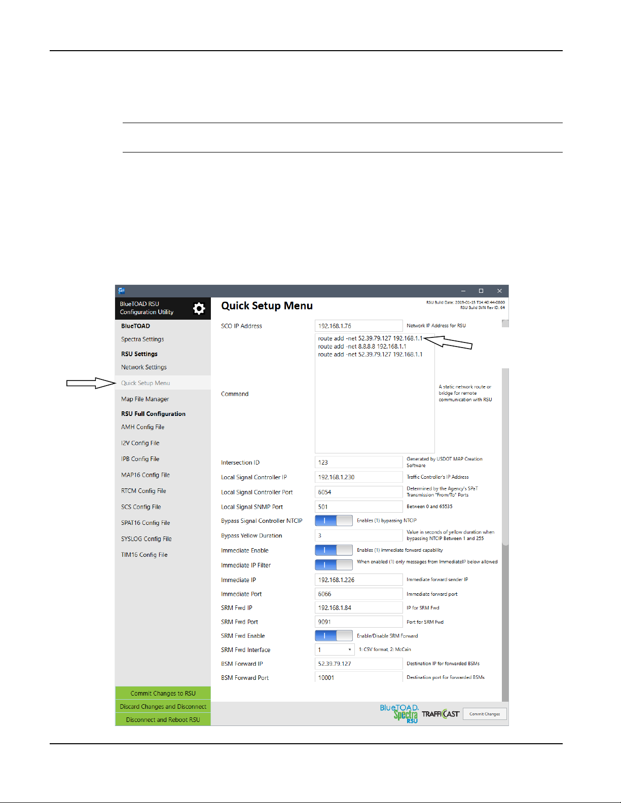
3. Set the Traffic Controller network and communications information.
a. Under the RSU Settings menu, select the Quick Setup Menu tab.
b. Change these settings and keep a record of the changes:
Important: Make sure that you keep a record of the new settings. If you do not know the
RSU IP address, you CANNOT log back into the RSU!
i. Confirm the IP Address change from Step 2, b, ii above:
SCO IP Address: (192.168.1.XXX)
ii. Change Command: route add -net IP (Default: 52.39.79.127 192.168.1.1), shown below
iii. Do NOT Change Intersection ID: (Default: 1001)
iv. Change Local Signal Controller IP (Default: 192.168.1.32)
c. On the BlueTOAD RSU Configuration Utility taskbar, select Commit Changes to submit
changes to the RSU.
-net IP
TrafficCast Quick Start—BlueTOAD Spectra and Spectra RSU
3-8 Revision 02 May 2019
Page 41
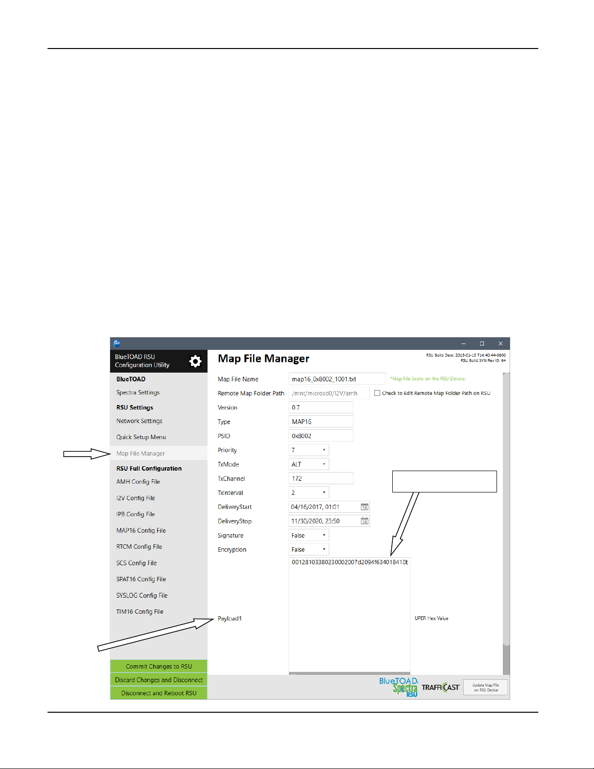
4. Upload a MAP File.
a. Under the RSU Settings menu, select the MAP File Manager tab.
b. Open the Message Encoder (for instructions, refer to Appendix 4, How to Create an RSU MAP
File, Step 48) and change these settings:
i. Change Intersection ID in MAP File Name: (Default: map16_0x8002_1001.txt)
ii. Copy the UPER Hex Value text (an example is given below) and Paste it into the
Payload1 field.
Example: Default UPER Hex Value for Intersection ID 1001:
00128103380230002007d2094f634018410b0c3c101402dc10580668000805000115eced
f9e5aecc0ff3c050535cf1e01880a0a2b95bc10a0a41a0000920840004580448000802000
015ec95ff29adb76ff7e050a024210000840044800100002bd8d407d35b71a00580a142c0
99400040380000afe630632d81319e0b027889202800089048000448310002080441000
2000058057834f6c072c940013ec580ee80008070000960c720851b2655043e04fb161f5a
04c092088000c901800064841000308033100020000583d57f276c9c0c15b813ec580aa8
00080700001605a1ee58afbbeb4224901400084844000424188002040110800100002bfa
e3dbb35fd1dcc680a0a0
c. On the BlueTOAD RSU Configuration Utility taskbar, select Update Map File on RSU
Device to submit these changes to the RSU.
BlueTOAD Spectra RSU Deployment
UPER Hex Value text
Payload1
TrafficCast Quick Start—BlueTOAD Spectra and Spectra RSU
Revision 02 May 2019 3-9
Page 42
BlueTOAD Spectra RSU Deployment
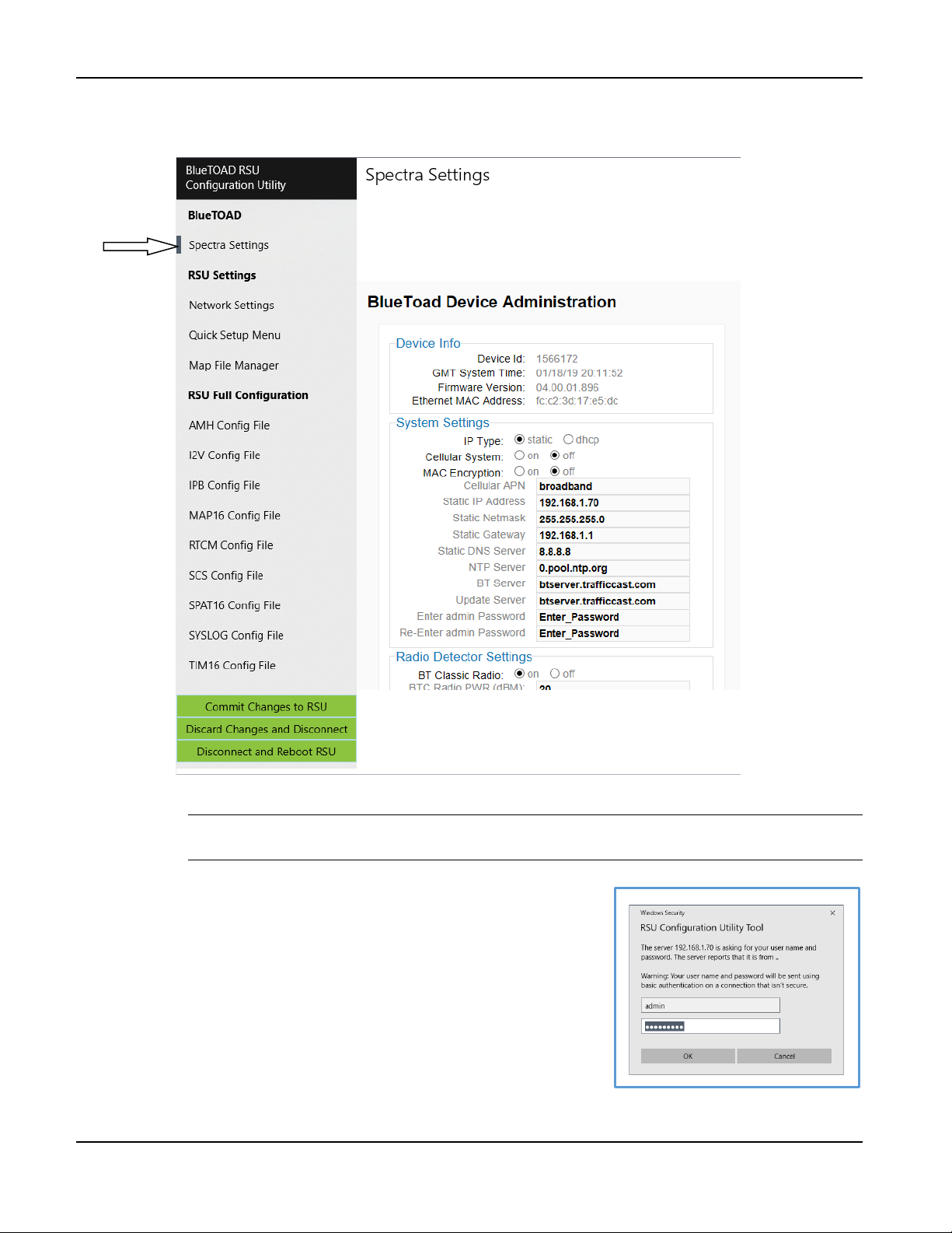
5. Set up the BlueTOAD Spectra communications parameters:
a. Under the BlueTOAD menu, select the Spectra Settings tab.
b. Change these settings and keep a record of the changes:
Important: Make sure that you keep a record of the new settings. If you do not know the
Static RSU IP address, you CANNOT log back into the RSU!
i. Enter Default Login information:
Username: admin
Password: 77admin77
ii. Change Static IP Address (Default: 192.168.1.77)
iii. Change Static Netmask (Default: 255.255.192.0)
iv. Change Static Gateway (Default: 10.12.1.1)
c. On the BlueTOAD RSU Configuration Utility taskbar,
select Commit Changes to submit changes to the RSU.
TrafficCast Quick Start—BlueTOAD Spectra and Spectra RSU
3-10 Revision 02 May 2019
Page 43
BlueTOAD Spectra RSU Deployment
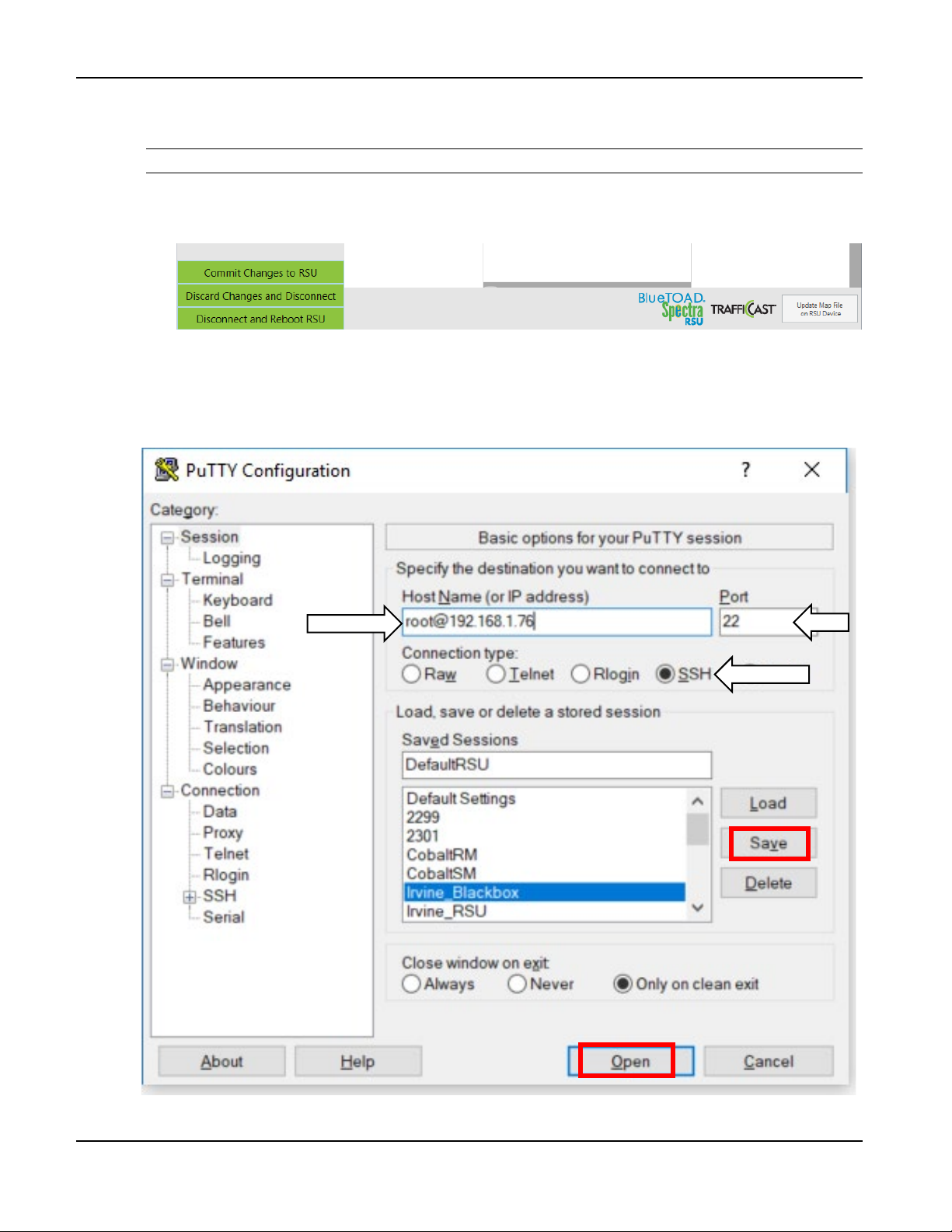
6. These final steps are to commit the changes you made (with the BlueTOAD Spectra RSU
Configuration Utility software) to the Spectra RSU:
Note: The selections that follow are green boxes in the bottom left of the screen.
a. Select Commit Changes to RSU.
b. Select Disconnect and Reboot RSU to restart the RSU.
Confirm that the BlueTOAD Spectra RSU is Broadcasting SPaT, MAP and BSM Data
1. Open PuTTY to start an SSH session into the RSU. Set the Host Name to [email protected], Port
to 22, Connection Type to SSH, and save the session as “DefaultRSU” for future use.
TrafficCast Quick Start—BlueTOAD Spectra and Spectra RSU
Revision 02 May 2019 3-11
Page 44
BlueTOAD Spectra RSU Deployment
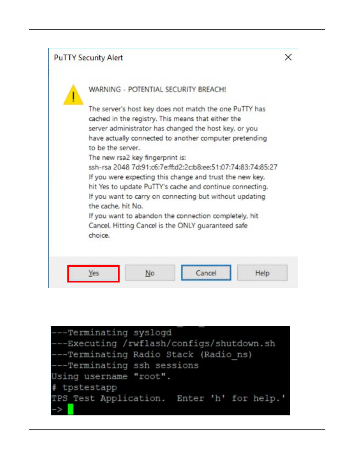
2. If prompted to accept the RSA key of the RSU click Yes.
3. After you connect to the RSU, verify the GPS functionality:
a. Run “tpstestapp”
b. Press Enter
TrafficCast Quick Start—BlueTOAD Spectra and Spectra RSU
3-12 Revision 02 May 2019
Page 45
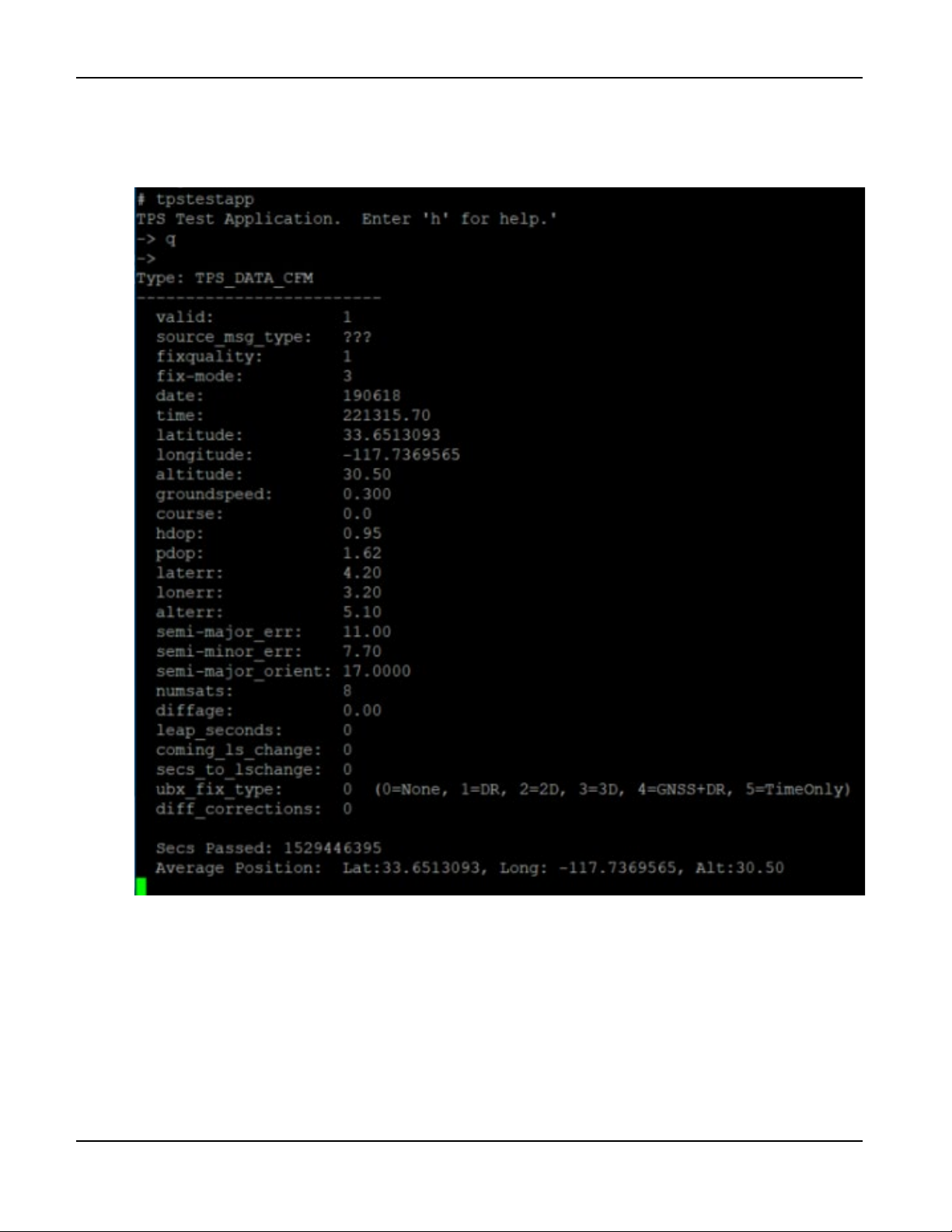
4. To query the GPS status:
a. Press q
b. Press Enter
BlueTOAD Spectra RSU Deployment
5. Check that the Average Position is being reported.
a. Press x
b. Press Enter
c. The BASH prompt is shown.
TrafficCast Quick Start—BlueTOAD Spectra and Spectra RSU
Revision 02 May 2019 3-13
Page 46
BlueTOAD Spectra RSU Deployment
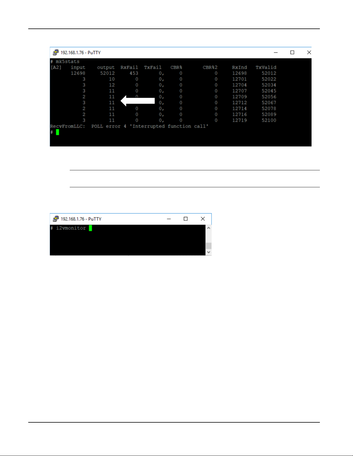
6. Run “mk5stats” to verify the operation of the DSRC radio:
7. Each row indicates the number of DSRC messages received and sent per second. Verify that the
output column is sending an average of 11 messages per second.
Note: These 11 messages are the 10 SPaT messages plus 1 MAP message generated
by the RSU.
8. Press Ctrl-C to stop the mk5stats stream and return to the BASH prompt.
9. Run “i2vmonitor” to verify the decoding of the controller timing messages:
TrafficCast Quick Start—BlueTOAD Spectra and Spectra RSU
3-14 Revision 02 May 2019
Page 47
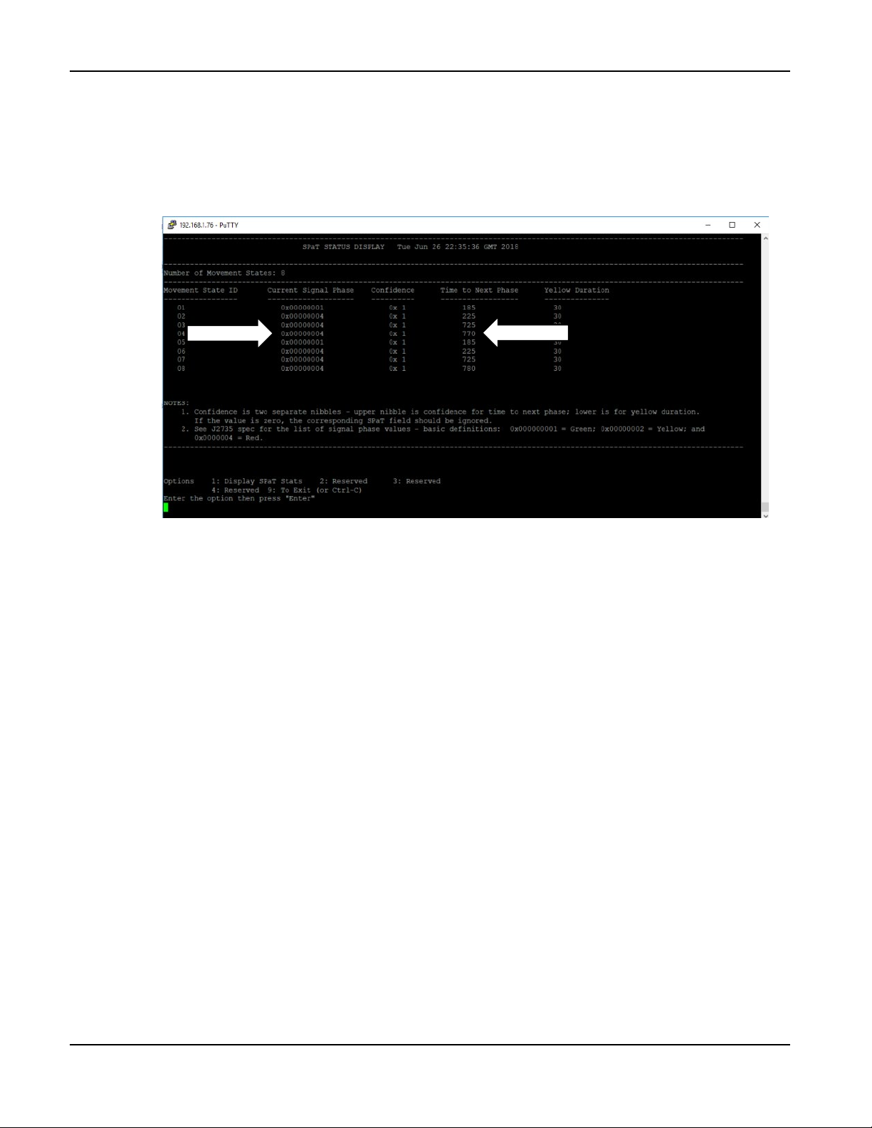
10. To view the SPaT message:
a. Press 1
b. Press Enter
c. The Current Signal Phase and Time to Next Phase fields should be counting down.
BlueTOAD Spectra RSU Deployment
11. Press Ctrl-C to stop the i2vmonitor stream.
12. When you have completed the confirmations, remove power (Ethernet cable) from the RSU.
TrafficCast Quick Start—BlueTOAD Spectra and Spectra RSU
Revision 02 May 2019 3-15
Page 48
BlueTOAD Spectra RSU Deployment
Field Installation of a BlueTOAD Spectra RSU
1. Guidelines to install an RSU enclosure:
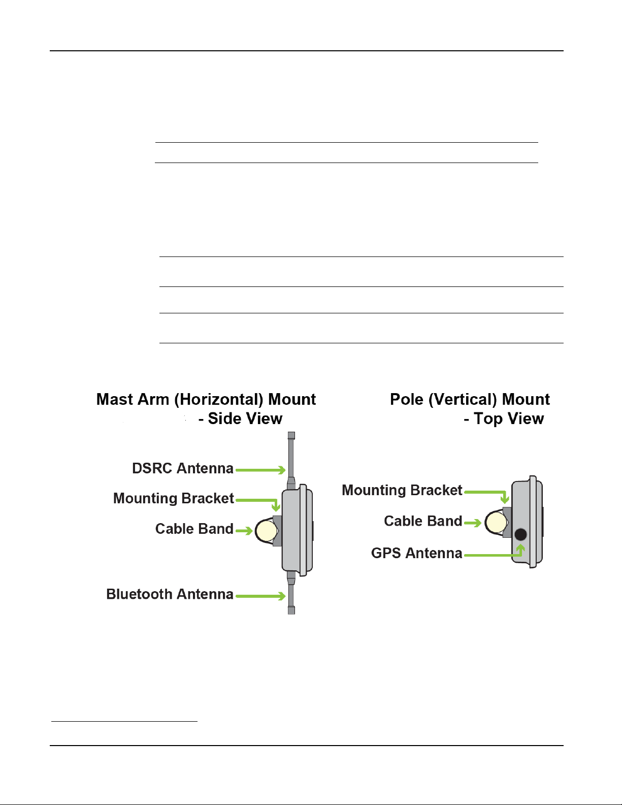
a. Mounting Structure—a Mast Arm or Signal Pole that is:
Near the roadside traffic signal cabinet, or appropriate 120 VAC power source
Note: The mounting pole should be near the cabinet for easy conduit access.
Has a mounting location with a clear line-of-sight from the RSU antennas to the target
road segment
b. Mounting Height—8 meters (26.3 feet) to 15 meters (49.2 feet) above the roadbed
c. Mount the Enclosure to a Mast Arm or Pole a Mast Arm6 or Pole
i. Insert the two metal Cable Bands through their slots in the Mounting Bracket.
Note: The Mounting Bracket is “dual-direction,” designed to mount on either a
horizontal or vertical pole.
ii. Wrap the Cable Bands around the pole.
Note: The Cable Bands are designed for mounting on Mast Arms, Poles, I-Beams or
other support structures up to 14” in diameter.
iii. Use a drill to tighten the Cable Bands with a 5/16” nut driver bit or equivalent.
6
The preferred installation is on a Mast Arm, as shown on the next page.
TrafficCast Quick Start—BlueTOAD Spectra and Spectra RSU
3-16 Revision 02 May 2019
Page 49
BlueTOAD Spectra RSU Deployment
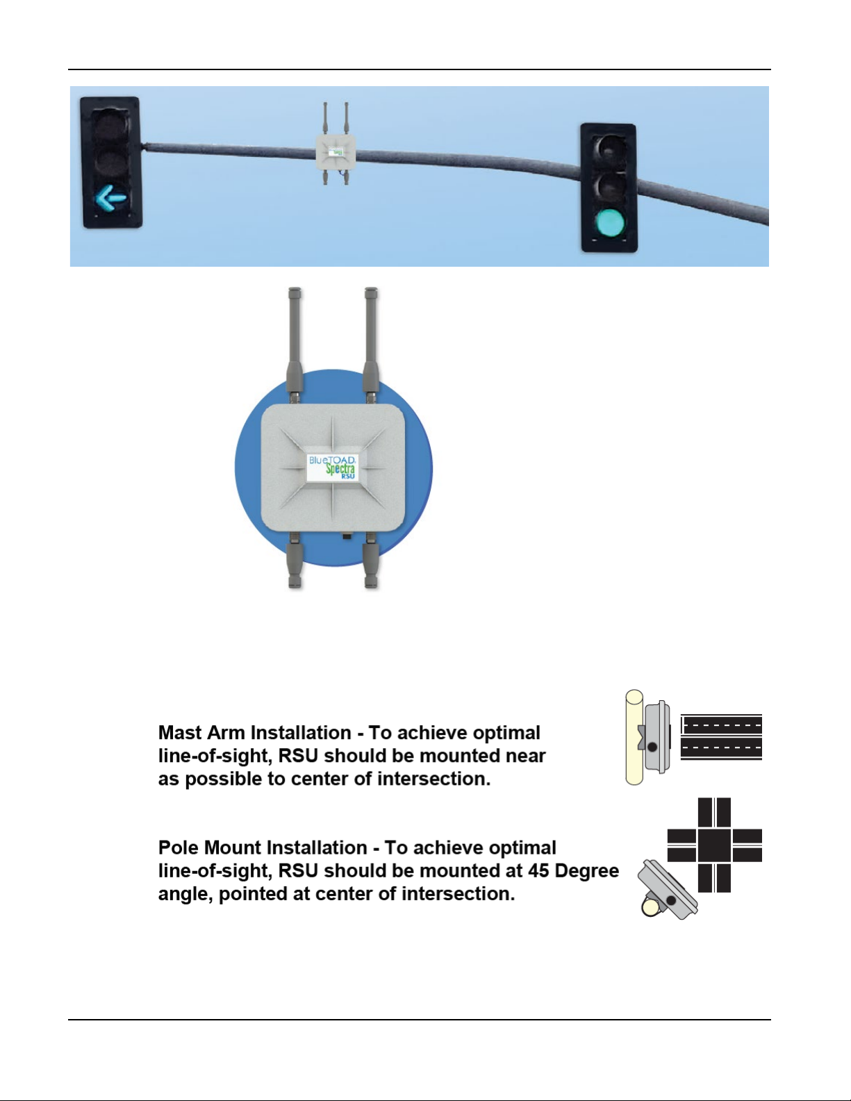
d. Align the Enclosure per your installation as shown below:
TrafficCast Quick Start—BlueTOAD Spectra and Spectra RSU
Revision 02 May 2019 3-17
Page 50
BlueTOAD Spectra RSU Deployment
2. Guidelines to route and connect the cables:
a. Traffic Closure—Close traffic lanes as necessary to pull cable.
b. CAT-5 Ethernet Cable
i. Pull the main CAT-5 Ethernet Cable through the roadside conduit from the roadside
cabinet to the RSU enclosure.
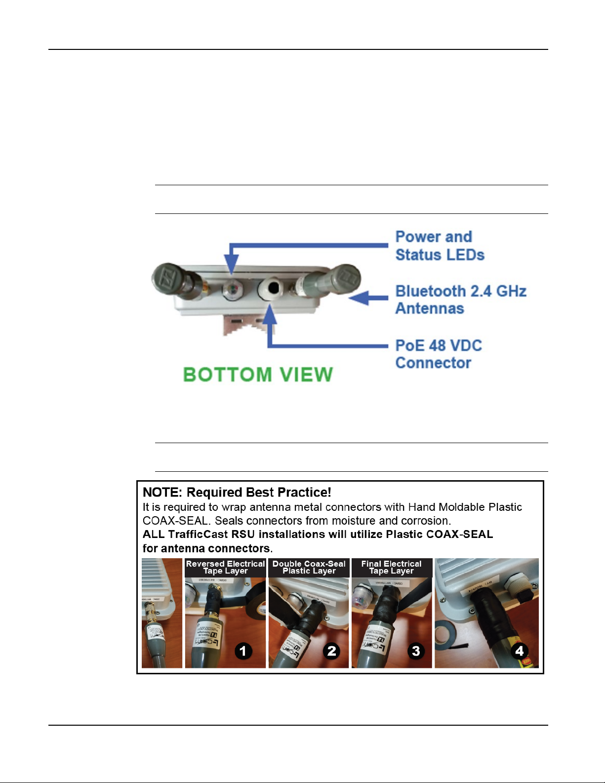
ii. Connect the Ethernet cable to the PoE 48 VDC Connector on the bottom of the RSU
enclosure.
Note: The PoE 48 VDC connector goes to the PoE Splitter that also sends data
from the Spectra RSU to the PoE Injector inside the cabinet.
Important: To seal the antenna connectors against rust and corrosion, protect them
per the Required Best Practice instructions shown below.
TrafficCast Quick Start—BlueTOAD Spectra and Spectra RSU
3-18 Revision 02 May 2019
Page 51
BlueTOAD Spectra RSU Deployment
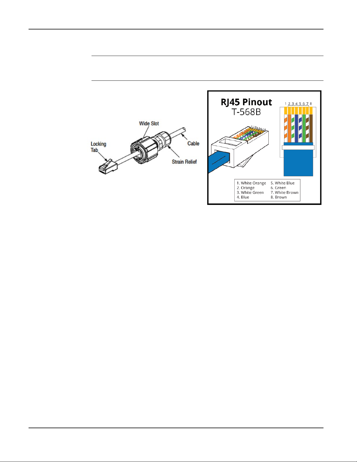
iii. Pass the cable through the Liquid-Tight Cable Gland of the Ethernet cable Coupler and
terminate it to an RJ45 connector per the pinout shown.
Note: You will have to remove the Strain Relief on the cable to pass it through the
Cable Gland. However, you can slide the Strain Relief away from the RJ-45
connector without cutting the Strain Relief.
TrafficCast Quick Start—BlueTOAD Spectra and Spectra RSU
Revision 02 May 2019 3-19
Page 52
BlueTOAD Spectra RSU Deployment
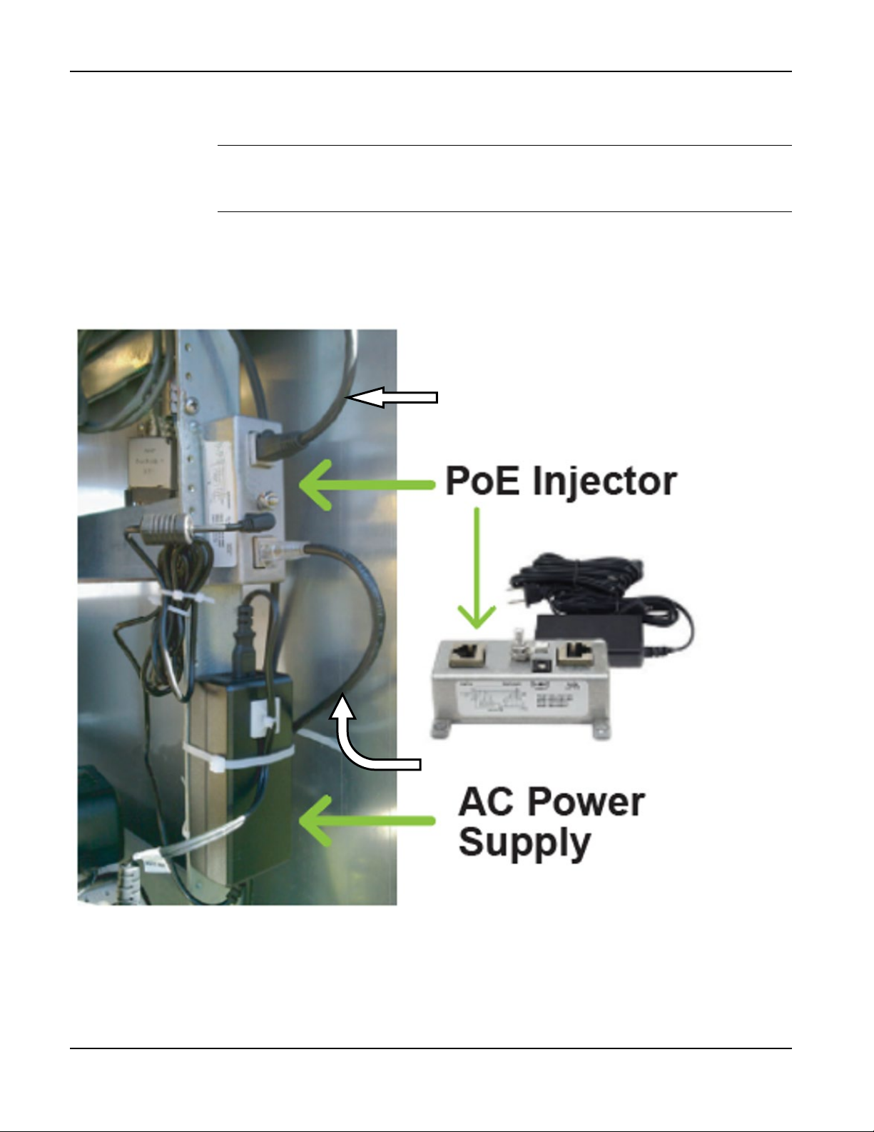
Main CAT-5 Ethernet Cable
c. Install the PoE Injector in the roadside cabinet:
i. Secure the PoE injector onto a flat surface inside the roadside cabinet.
Note: The PoE Injector has two RJ-45 ports:
• Data—connects to the network Ethernet switch, router or hub
• Data and Power—connects to the PCB of the RSU, i.e. to the PoE Splitter
ii. Connect the ground wire.
iii. Connect the Main CAT-5 Ethernet Cable to the PoE Injector.
iv. Connect an Ethernet cable from the PoE Injector to the cabinet LAN/WAN Ethernet
Network Switch or Router.
Ethernet Cable to Ethernet
Network Switch or Router
v. Connect the Ethernet Network Switch to the Traffic Controller.
vi. Connect the AC Power Supply to the PoE Injector.
vii. Plug the 110 VAC cord into an AC power outlet receptacle.
3-20 Revision 02 May 2019
TrafficCast Quick Start—BlueTOAD Spectra and Spectra RSU
Page 53
BlueTOAD Spectra RSU Deployment
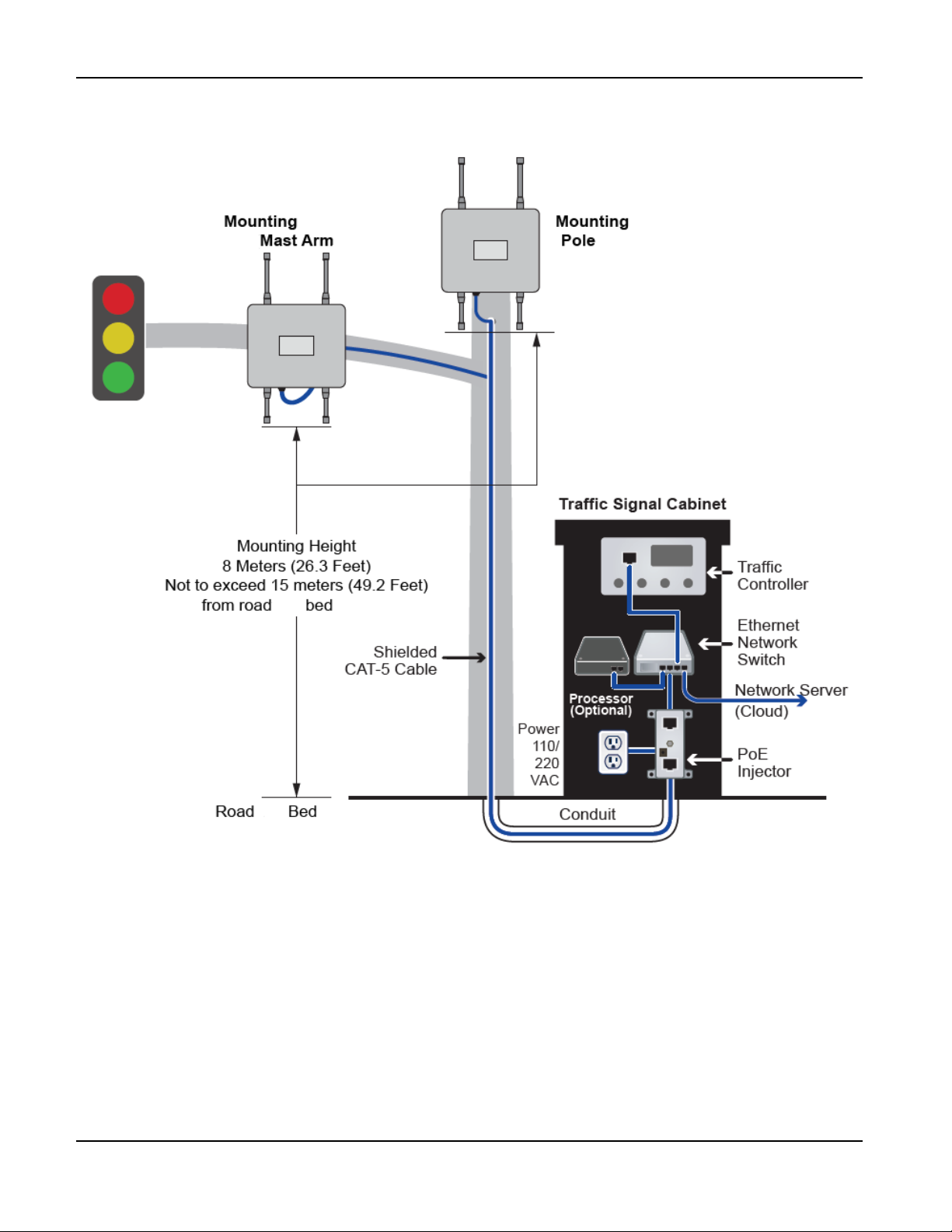
3. This is the completed installation of a Spectra RSU that shows both possible ways to mount the
enclosure—on a Mast Arm and a Pole:
TrafficCast Quick Start—BlueTOAD Spectra and Spectra RSU
Revision 02 May 2019 3-21
Page 54
BlueTOAD Spectra RSU Deployment
Testing a BlueTOAD Spectra RSU After Field Installation
1. Plug the Ethernet cable into the PoE Injector to power ON the Spectra RSU.
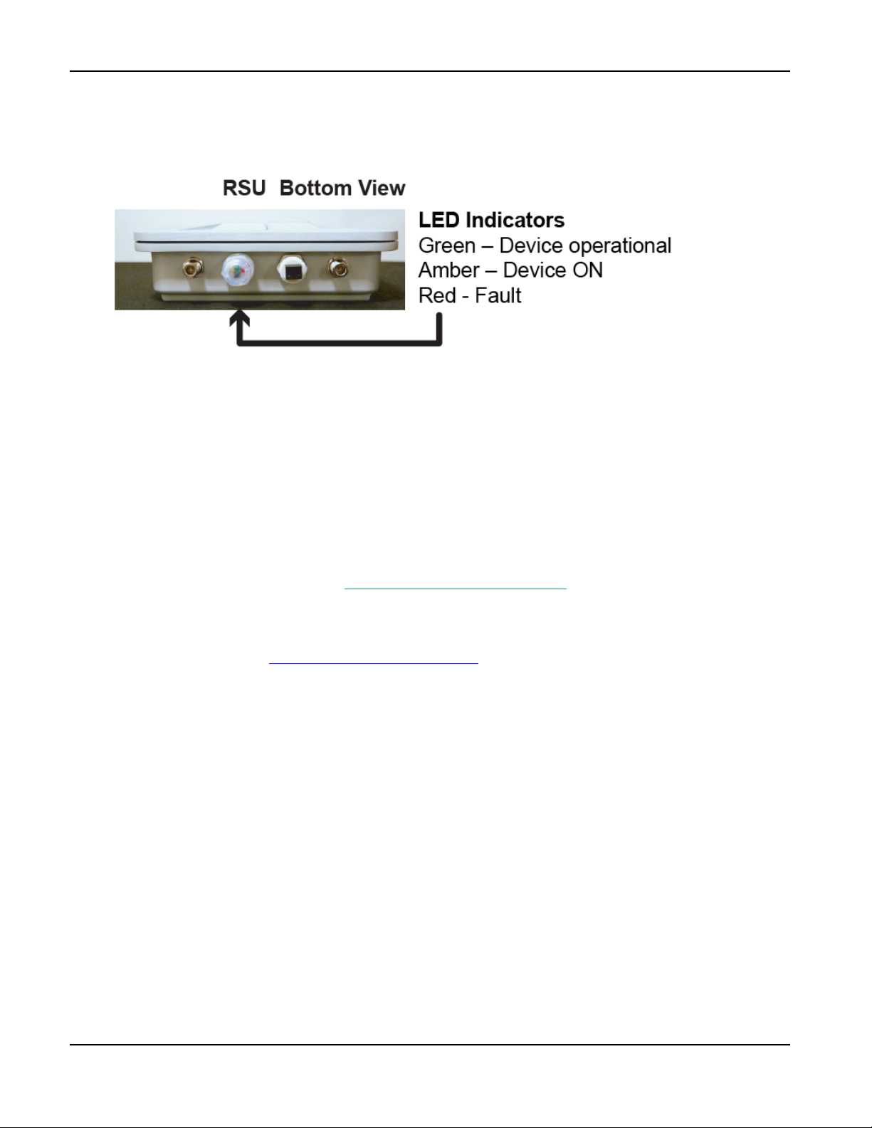
2. Confirm that all LEDs are normal after the unit initializes:
3. Before leaving the location:
a. After the unit is Powered ON, call TrafficCast Customer Support at (608) 713-9299.
i. Tell TrafficCast the device ID number and that the LEDs are normal.
ii. Confirm from TrafficCast that the network is transmitting the SPaT and MAP data from
this unit.
b. Access TrafficCast RSU status using the web-based BlueARGUS software.
i. Login credentials (Username and Password) are provided to each User, based on their
predetermined Role (Admin, Tech1 or Tech2) when the Account is initially setup.
ii. BlueARGUS Website: https://bluetoad.trafficcast.com/
4. Add each installed TrafficCast RSU unit to a compiled list of unit location data. For each unit, keep
a record of device ID, location, and installation date.
TrafficCast Support Website: https://trafficcast.zendesk.com
TrafficCast Quick Start—BlueTOAD Spectra and Spectra RSU
3-22 Revision 02 May 2019
Page 55
4. Appendix—How to Create an RSU MAP File
Objective
This procedure outlines the steps to produce an SAE J2735 compliant MAP file. J2735 messages are
encoded using unaligned packed encoding rules (UPER) when transmitted from the roadside unit based on
the 2016 standard’s requirements. This procedure assumes that you are familiar with traffic control
terminology, intersection geometry and layout.
Material Requirements
• Windows PC with internet connection and web browser
• Customer intersection location
• Intersection diagram or equivalent
Map File Creation Procedure
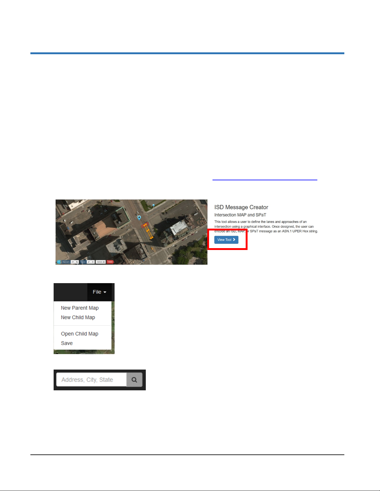
1. Open the USDOT Connected Vehicles Tools website: https://webapp.connectedvcs.com/
2. Click View Tool to open the ISD Message Creator.
3. Click File > New Parent Map to start a new parent map.
4. In the search bar, enter an address near the intersection location.
TrafficCast Quick Start—BlueTOAD Spectra and RSU
Revision 02 May 2019 4-1
Page 56
Appendix—How to Create an RSU MAP File
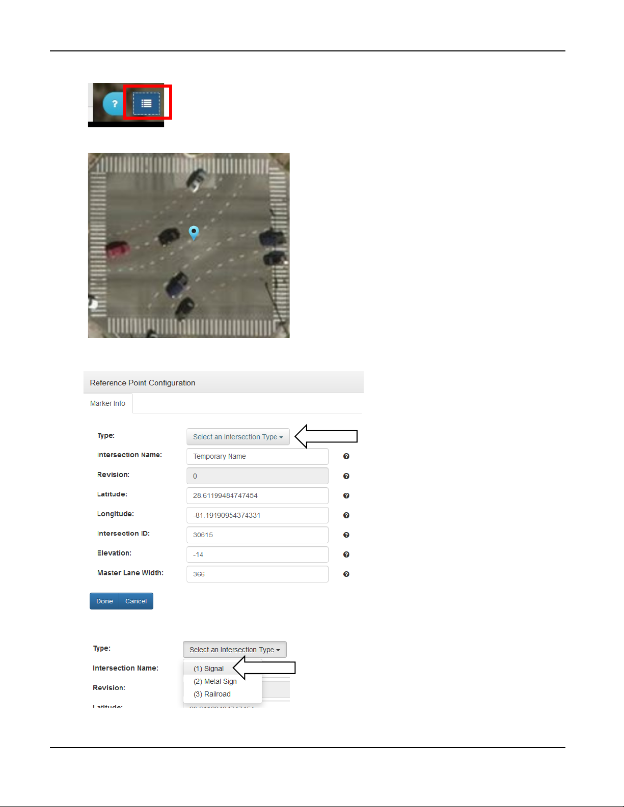
5. Center the view on the intersection and click the Builder icon.
6. Put the Reference Point Marker in the center of the intersection.
7. The Reference Point Configuration menu should open after you place the Reference Point Marker.
If the menu does not open, left click on the Reference Point Marker to open it.
8. In the Type field, select (1) Signal as the Intersection Type and click Done.
TrafficCast Quick Start—BlueTOAD Spectra and Spectra RSU
4-2 Revision 02 May 2019
Page 57
Appendix—How to Create an RSU MAP File
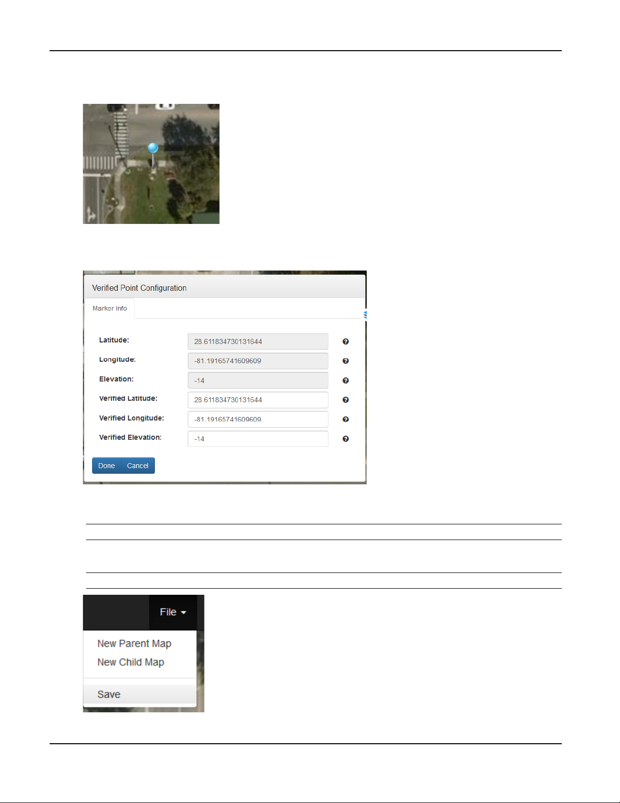
9. Put the Verified Point Marker in an accessible and measurable location such as the traffic cabinet or
measured on-site field survey point if available.
10. The Verified Point Configuration menu should open when you place the Verified Point Marker.
If the menu does not open, left click on the Reference Point Marker to open it.
11. If the Verified Latitude and Verified Longitude values are available from on-site field surveys,
enter them in the noted fields then click Done. If verified values are not available, just click Done.
Note: The internal GPS of the BlueTOAD Spectra RSU automatically calculates its Elevation.
12. Click File > Save to save the Parent Map. Then click Continue.
Note: Do NOT press Enter—make sure you click Continue.
TrafficCast Quick Start—BlueTOAD Spectra and Spectra RSU
Revision 02 May 2019 4-3
Page 58
Appendix—How to Create an RSU MAP File
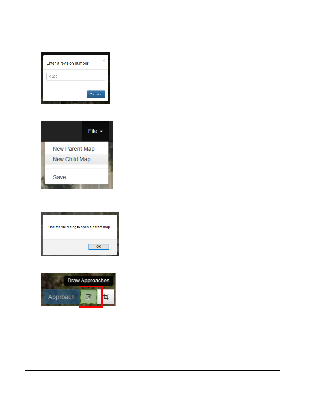
13. When prompted to enter a revision number, enter 0, click Continue, and save the Parent Map to the
local disk.
14. Click File > New Child Map to start building the Child Map.
15. Click OK on the file dialog notice to open the parent map; locate, select and open the Parent Map
created in the previous steps.
16. Click on the Draw Approaches button in the bottom left corner to select the draw approach boxes.
TrafficCast Quick Start—BlueTOAD Spectra and Spectra RSU
4-4 Revision 02 May 2019
Page 59
Appendix—How to Create an RSU MAP File
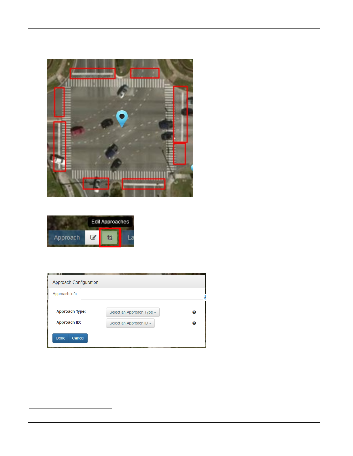
17. Draw approach boxes across every Ingress and Egress7 approach relative to the intersection over the
stop bar and across every lane as shown.
18. Use the Edit Approaches button to rotate, expand or contract the approach boxes as needed.
19. Starting with the northmost approach, left click on each Approach box to open the Approach
Configuration Menu.
20. Under Approach Type, select Ingress if the lanes are directed into the intersection and Egress if
the lanes are directed out of the intersection; select the lowest Approach ID available starting at 01
then click Done.
21. Repeat Step 19 and Step 20 for all Approaches in a clockwise order until all approaches are drawn.
7
Ingress = Going into (entering) an intersection; Egress = Going out of (leaving) an intersection
TrafficCast Quick Start—BlueTOAD Spectra and Spectra RSU
Revision 02 May 2019 4-5
Page 60
Appendix—How to Create an RSU MAP File
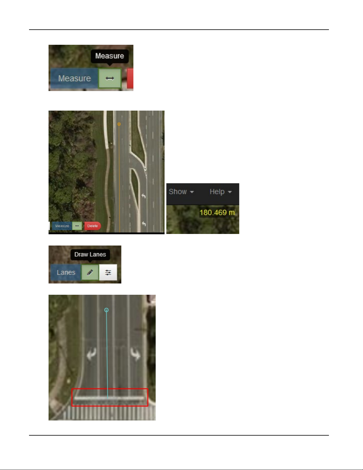
22. Select the Measure tool.
23. Left click on the stop bar of an approach, measure the distance from the stop bar to at least 180
meters away using the measured distance on the upper right, and note the location with a landmark.
24. Left click on the Draw Lanes button.
25. Left click on the center of the lane at the stop bar to start drawing lanes.
TrafficCast Quick Start—BlueTOAD Spectra and Spectra RSU
4-6 Revision 02 May 2019
Page 61
Appendix—How to Create an RSU MAP File
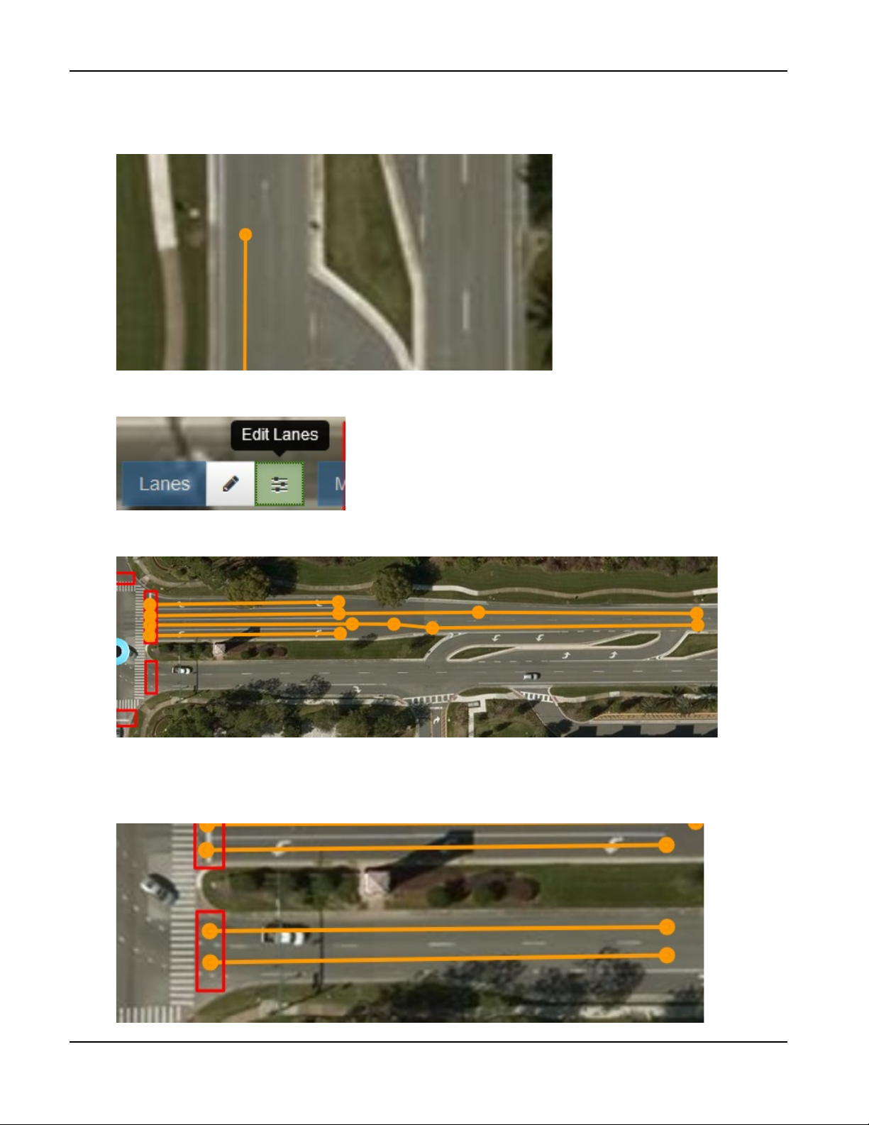
26. Use the middle mouse button to drag the view out to the measured landmark. Left click on the
center of the lane as needed to remain in the center.
27. Double click on the desired endpoint of the lane to terminate the lane.
28. As needed to edit, left click on the Edit Lanes button and select the drawn lane. Click on the opaque
midpoints to add nodes and use the Delete key to delete nodes.
29. Repeat the process for other individual lanes of the approach. For dedicated right and left turn lanes,
span the entirety of the lanes until completed as shown (Rotated 90° CW).
30. To draw the Egress lane, click on the Draw Lanes button, click on the center of the Egress lane
within the approach box, draw the egress lane to at least the same length as the left turn lane, and
double click on the endpoint to terminate the lane; repeat this process for all Egress lanes in the
approach box until completed as shown (Rotated 90° CW).
TrafficCast Quick Start—BlueTOAD Spectra and Spectra RSU
Revision 02 May 2019 4-7
Page 62
Appendix—How to Create an RSU MAP File
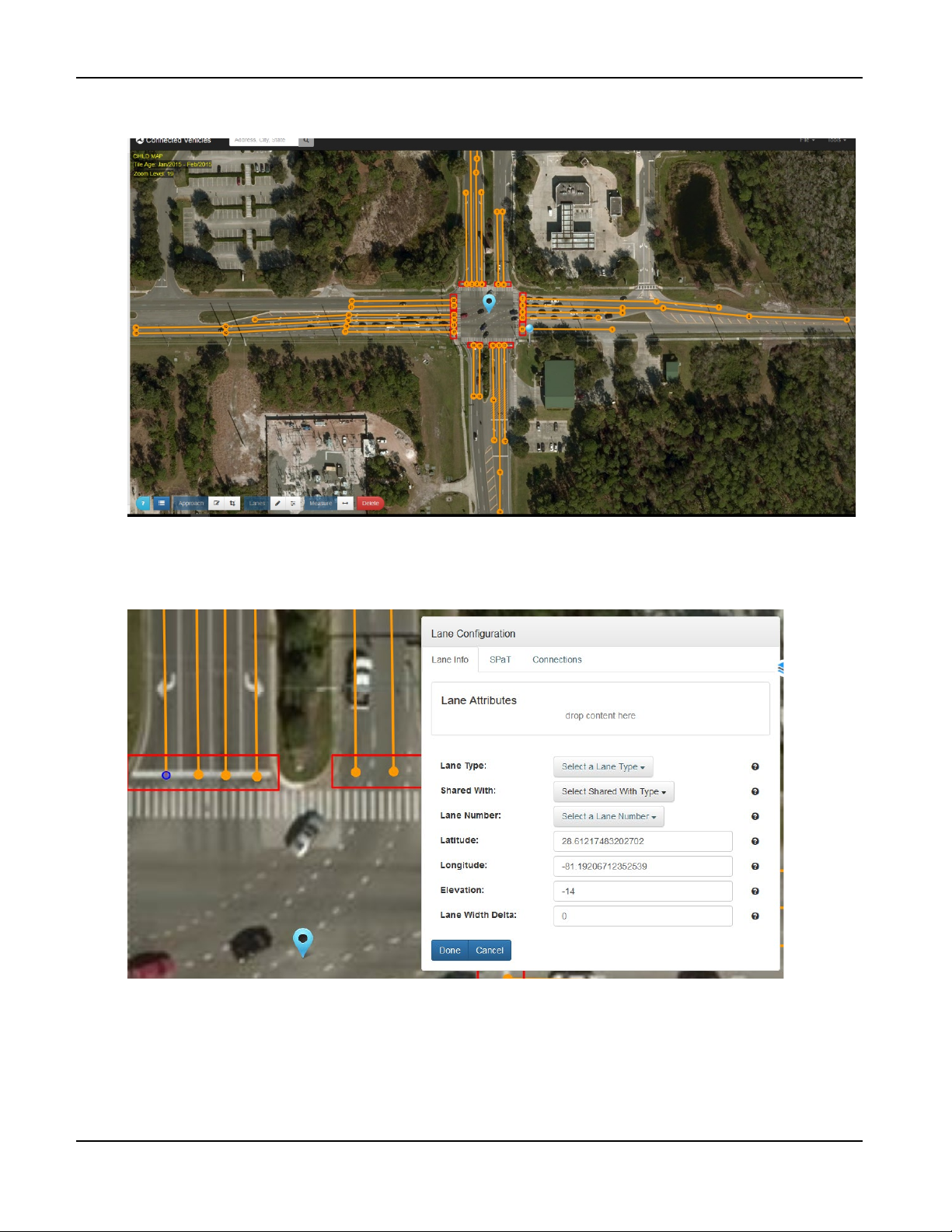
31. Repeat the process of drawing lanes until all lanes of the intersection are completely drawn as shown.
32. Click on the starting point of the left-most lane in the northern Ingress approach box to open the
Lane Configuration menu.
TrafficCast Quick Start—BlueTOAD Spectra and Spectra RSU
4-8 Revision 02 May 2019
Page 63

33. Left click on the Builder Menu to open the Lane tab.
Appendix—How to Create an RSU MAP File
TrafficCast Quick Start—BlueTOAD Spectra and Spectra RSU
Revision 02 May 2019 4-9
Page 64
Appendix—How to Create an RSU MAP File
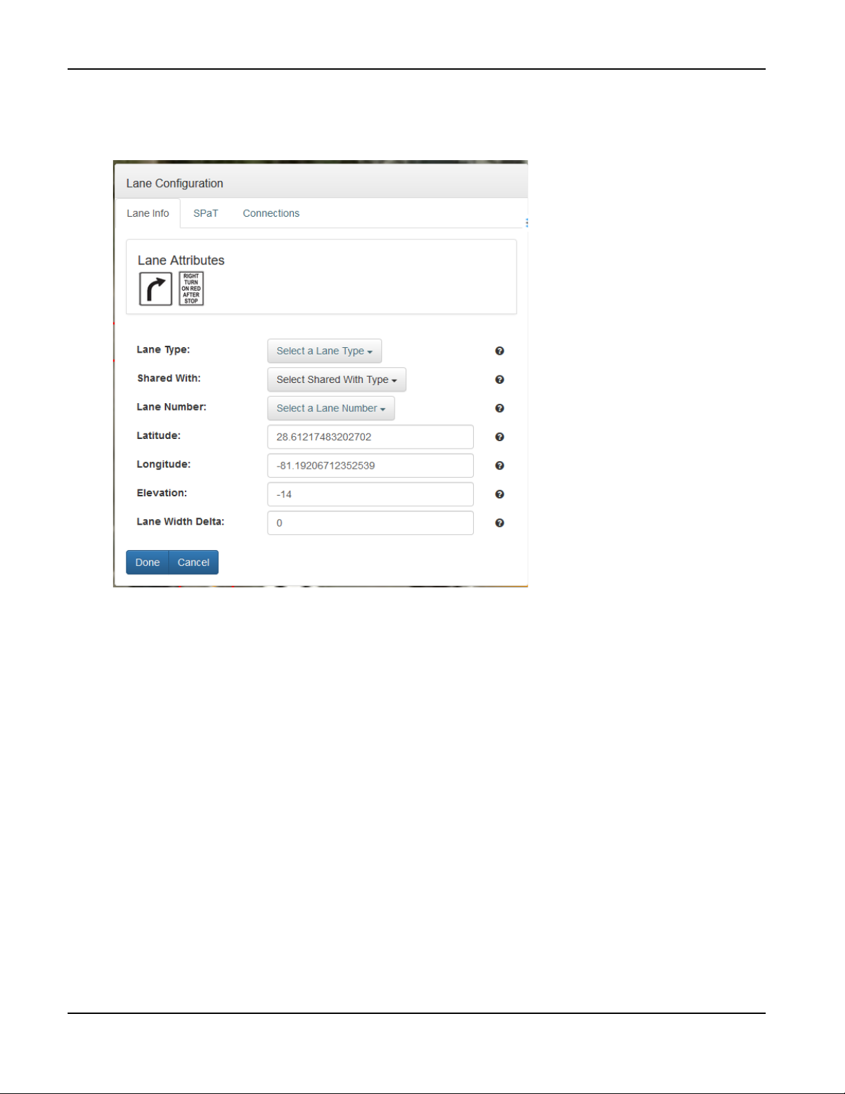
34. Drag and drop the allowed maneuvers from the appropriate icons in the Lane tab to the Lane
Attributes box in the Lane Configuration menu; to determine the allowed maneuvers, refer to the
intersection diagram, lane markings, and signage.
TrafficCast Quick Start—BlueTOAD Spectra and Spectra RSU
4-10 Revision 02 May 2019
Page 65
Appendix—How to Create an RSU MAP File
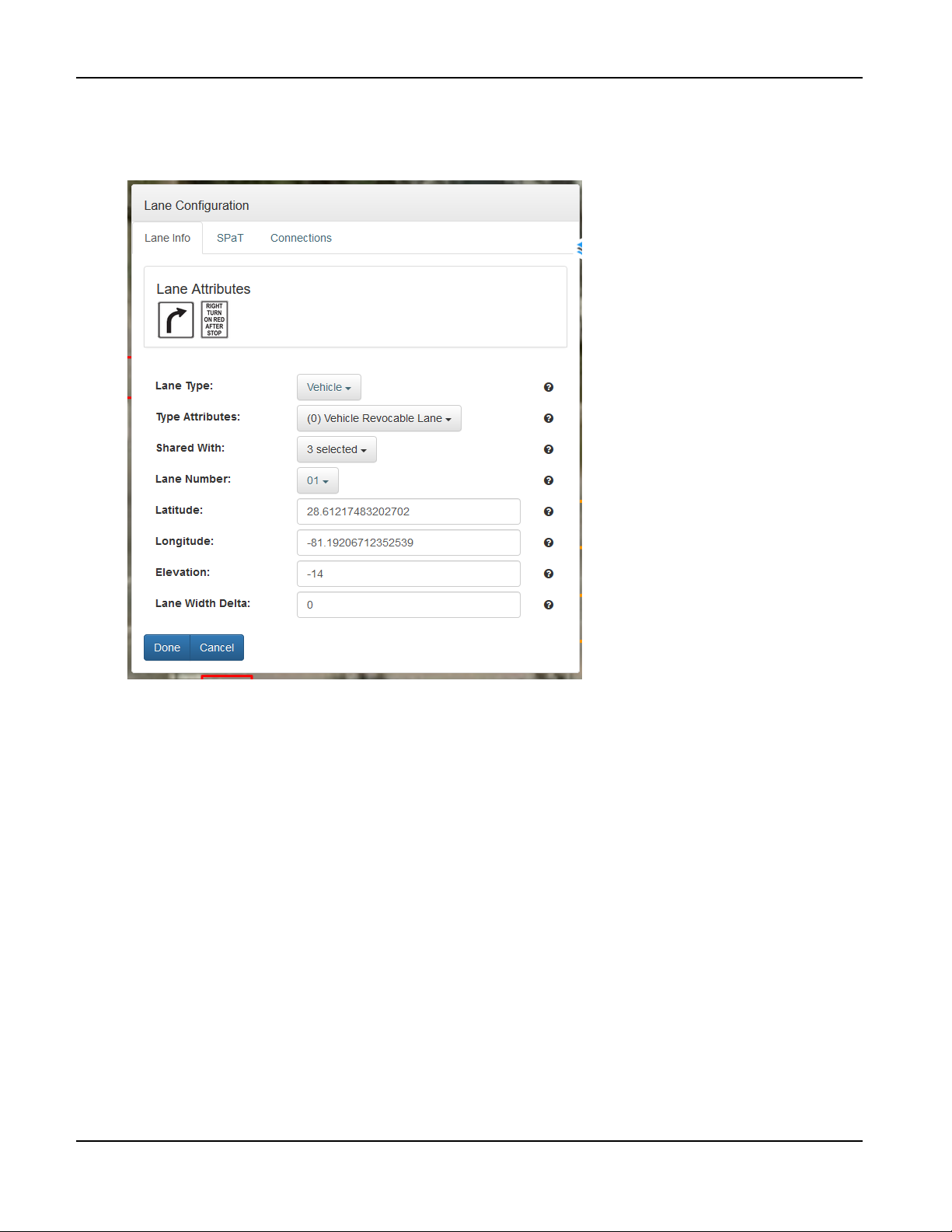
35. In the Lane Type field, select Vehicle; in the Type Attributes field, select (0) Vehicle Revocable
Lane; in the Shared With field, select (3) Individual Motorized (4) Bus (5) Taxi; and, in the Lane
Number, select the lowest available lane number starting with 01; when done, click Done.
TrafficCast Quick Start—BlueTOAD Spectra and Spectra RSU
Revision 02 May 2019 4-11
Page 66
Appendix—How to Create an RSU MAP File
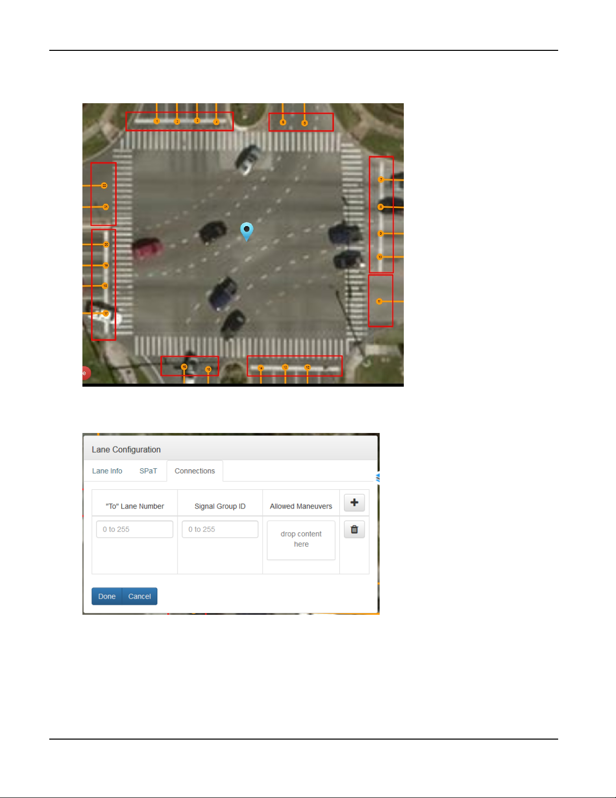
36. Repeat this process for all remaining lanes in the intersection. When you are done, the starting node
in each lane will be identified with its number as shown.
37. Click on node designated 1 to open the Lane Configuration menu and click the Connections tab.
TrafficCast Quick Start—BlueTOAD Spectra and Spectra RSU
4-12 Revision 02 May 2019
Page 67

38. Left click on the Builder Menu to open the Lane tab.
Appendix—How to Create an RSU MAP File
39. You should have a diagram of the intersection provided by a traffic engineer. Open the file of the
intersection diagram. An example diagram is shown below.
TrafficCast Quick Start—BlueTOAD Spectra and Spectra RSU
Revision 02 May 2019 4-13
Page 68
Appendix—How to Create an RSU MAP File
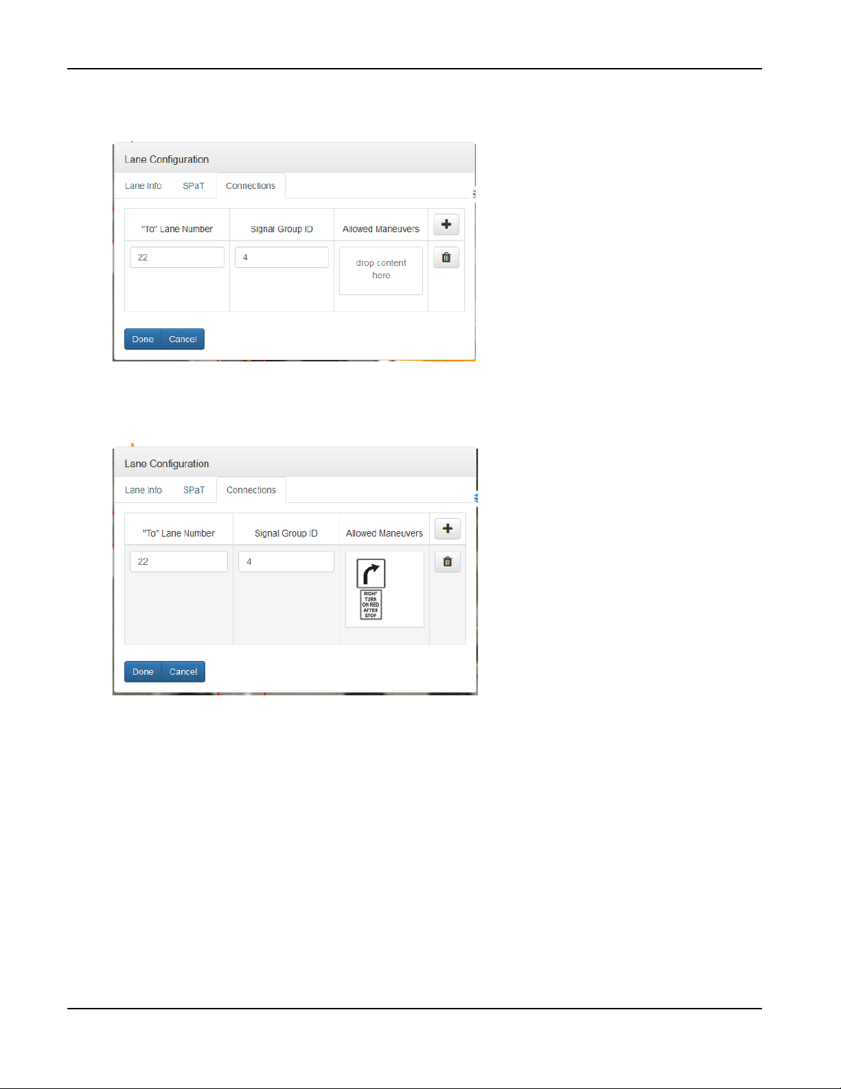
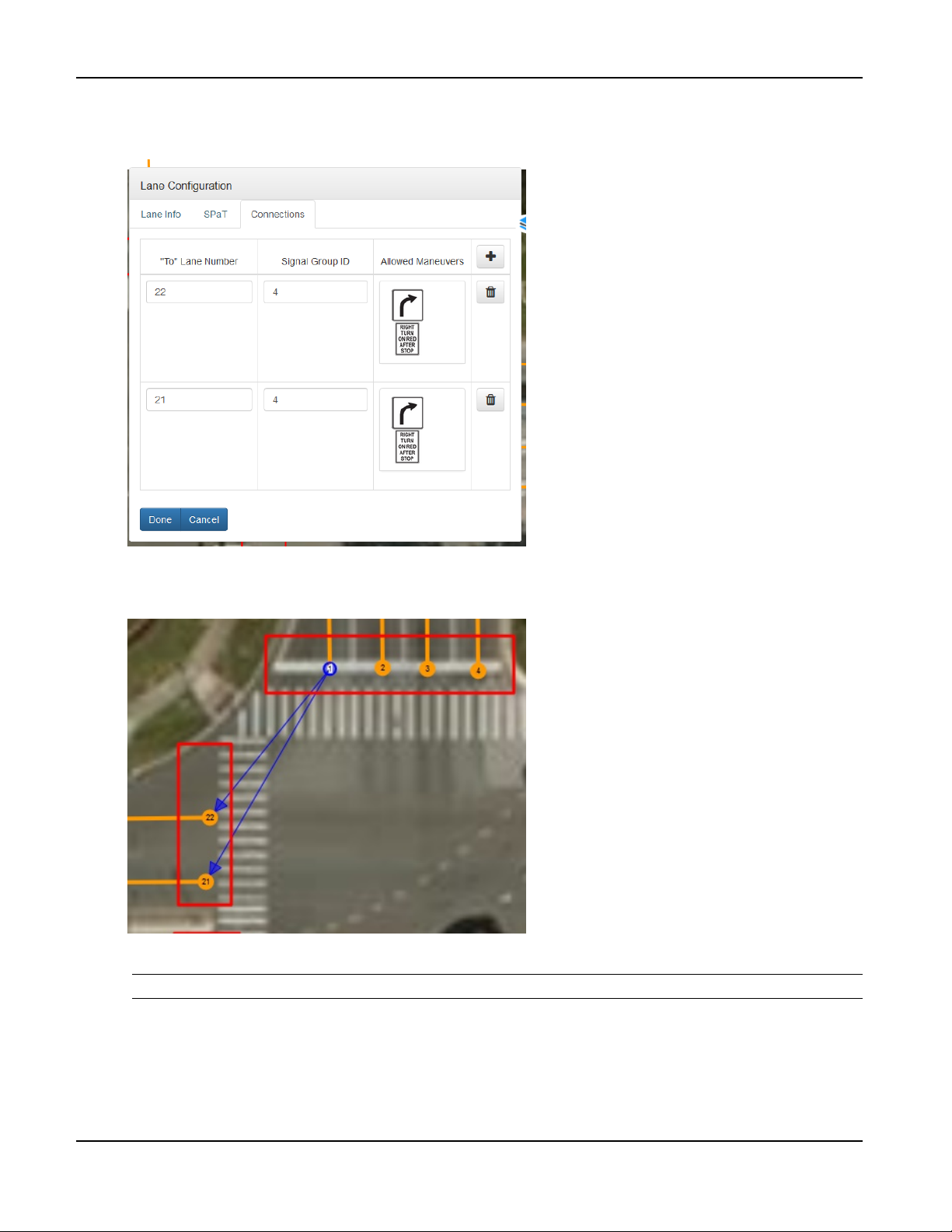
40. Using the intersection diagram as a reference, enter the destination lane number in the “To” Lane
Number field and the phase number associated with the movement in the Signal Group ID field.
41. Drag and drop the allowed maneuvers for the given phase and lane number from the Lane tab of
the Builder menu to the Allowed Maneuvers Box in the Connections tab window.
TrafficCast Quick Start—BlueTOAD Spectra and Spectra RSU
4-14 Revision 02 May 2019
Page 69
Appendix—How to Create an RSU MAP File
42. Use the + button in the Connections tab window to add more connections and repeat the process
as needed. When done, click Done.
43. Click again on node 1. Blue arrows will be visible to show established connections.
44. Repeat this process for every Ingress lane in the intersection.
Note: Egress lanes do not need connections.
TrafficCast Quick Start—BlueTOAD Spectra and Spectra RSU
Revision 02 May 2019 4-15
Page 70
Appendix—How to Create an RSU MAP File
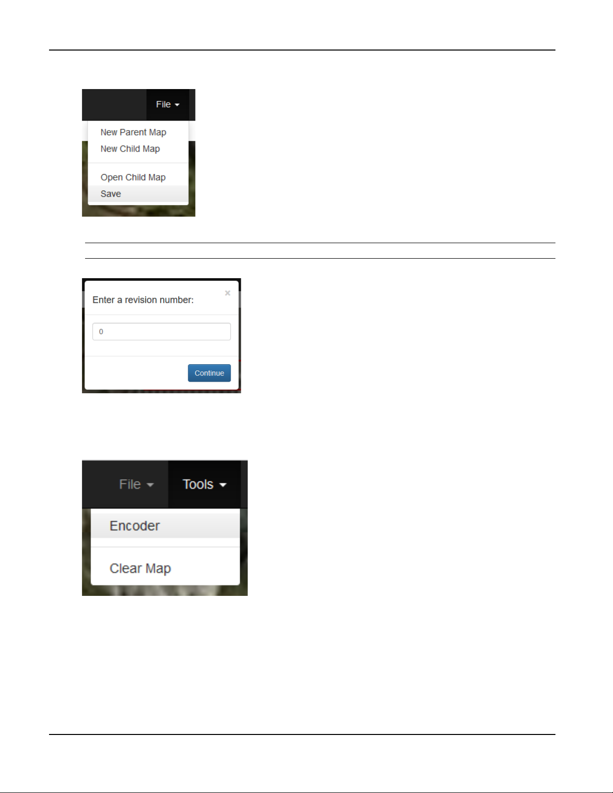
45. Click File > Save to save the Child Map.
46. When prompted, enter the revision number starting with 0. Then click Continue.
Note: Do NOT press Enter—make sure you click Continue.
47. Save the Child Map to the same directory on the local disk as the Parent Map. Whenever you make
significant edits and revisions to the Child Map, increment the revision number by 1.
48. Click Tools > Encoder to open the Message Encoder.
TrafficCast Quick Start—BlueTOAD Spectra and Spectra RSU
4-16 Revision 02 May 2019
Page 71
Appendix—How to Create an RSU MAP File
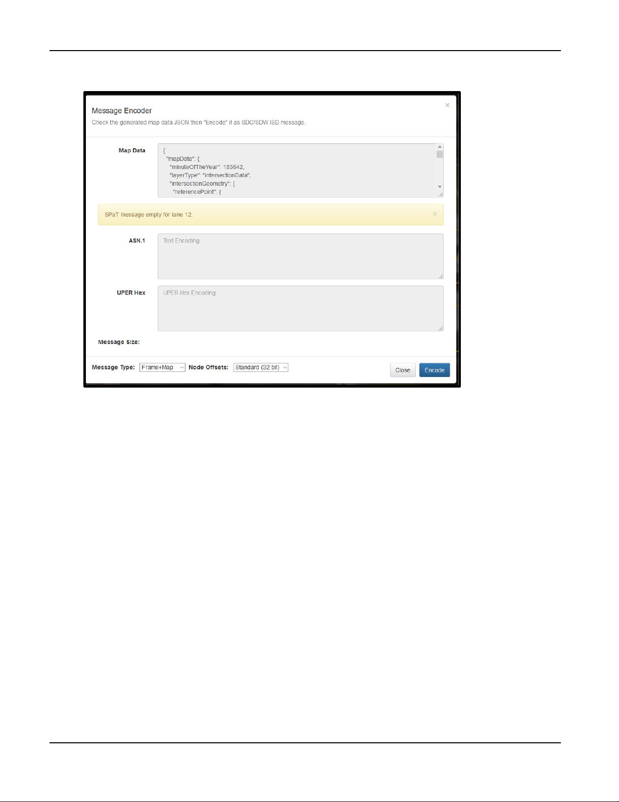
49. For Message Type, select Frame+Map and, for Node Offsets, select Standard (32 bit)
.
TrafficCast Quick Start—BlueTOAD Spectra and Spectra RSU
Revision 02 May 2019 4-17
Page 72
Appendix—How to Create an RSU MAP File
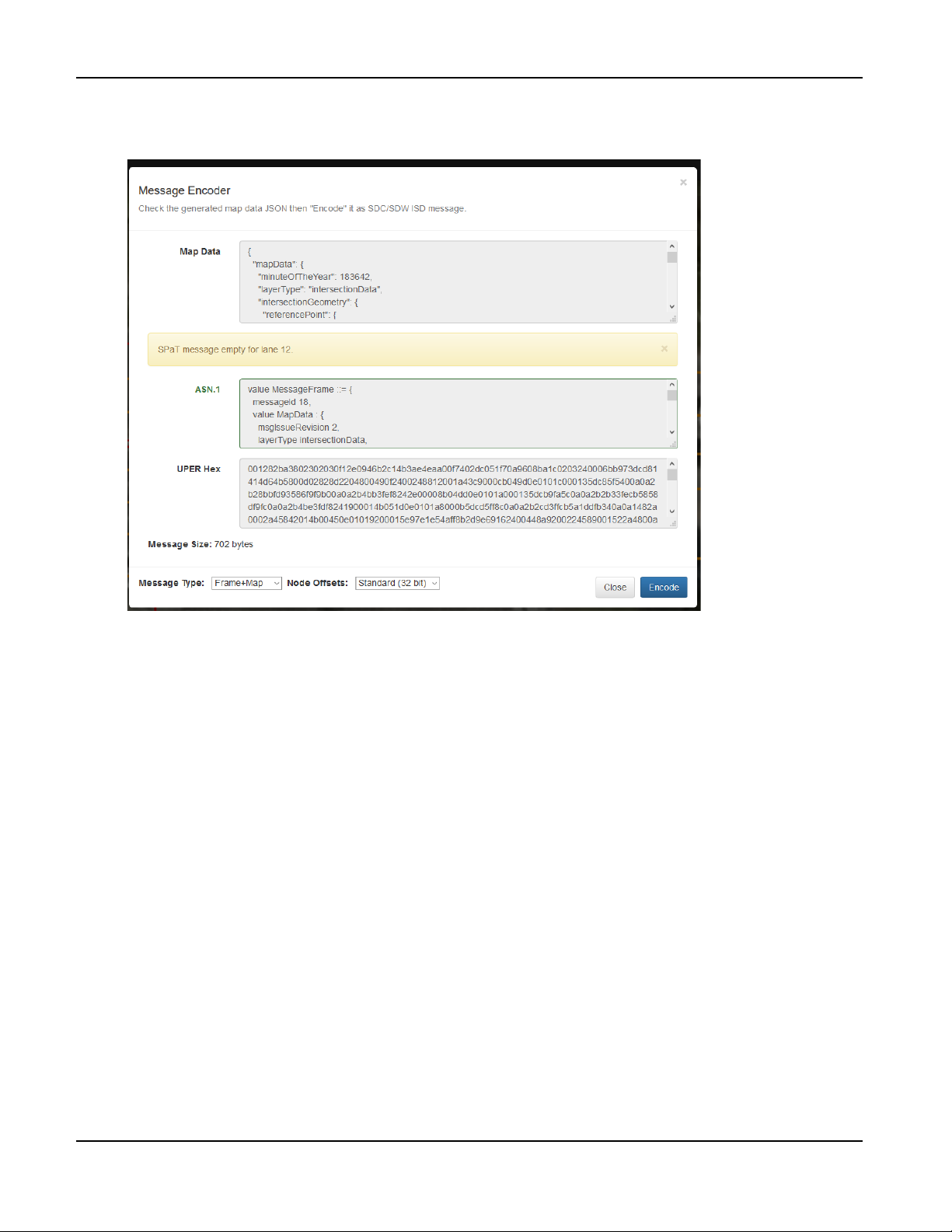
50. Click Encode. Ignore the warning for the SPaT message because this instruction is for building
MAP messages. If there are no errors, the UPER Hex string will populate as shown.
51. If the message size exceeds 1400 bytes, the RSU will not be able to support the payload size.
Reduce the size by deleting excess points in lanes.
TrafficCast Quick Start—BlueTOAD Spectra and Spectra RSU
4-18 Revision 02 May 2019
Page 73
5. Appendix—How to Manually Configure a BlueTOAD Spectra RSU
Supplement to Factory “Stock” RSU Configuration Procedure (Pages 3-6 thru 3-11)
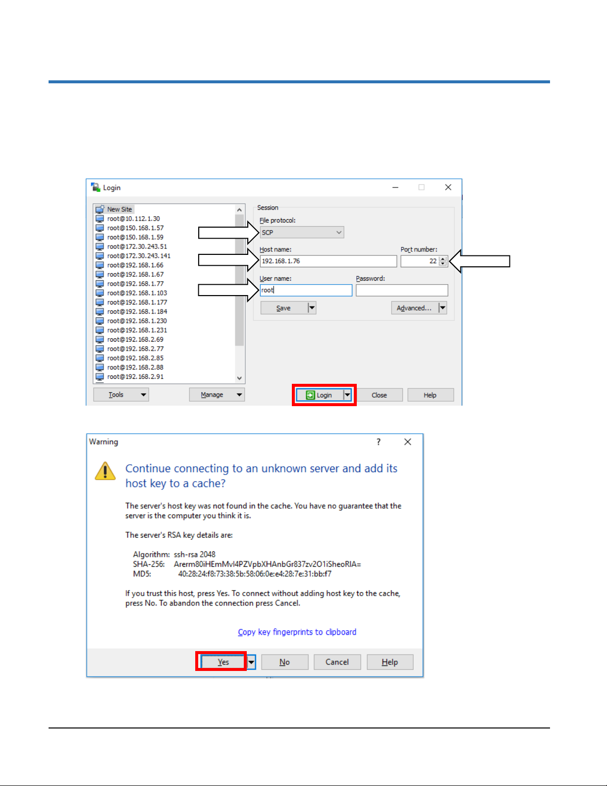
1. Open WinSCP to start an SCP file transfer session with the RSU.
2. In the Login window, select New Site on the left window pane, set the File protocol to SCP, Host
name to 192.168.1.76, Port Number to 22 and User name to root. Click Login to connect to the
RSU.
3. If asked to accept the RSA key from the RSU when connecting, click Yes to accept and continue.
TrafficCast Quick Start—BlueTOAD Spectra and RSU
Revision 02 May 2019 5-1
Page 74
Appendix—How to Manually Configure a BlueTOAD Spectra RSU
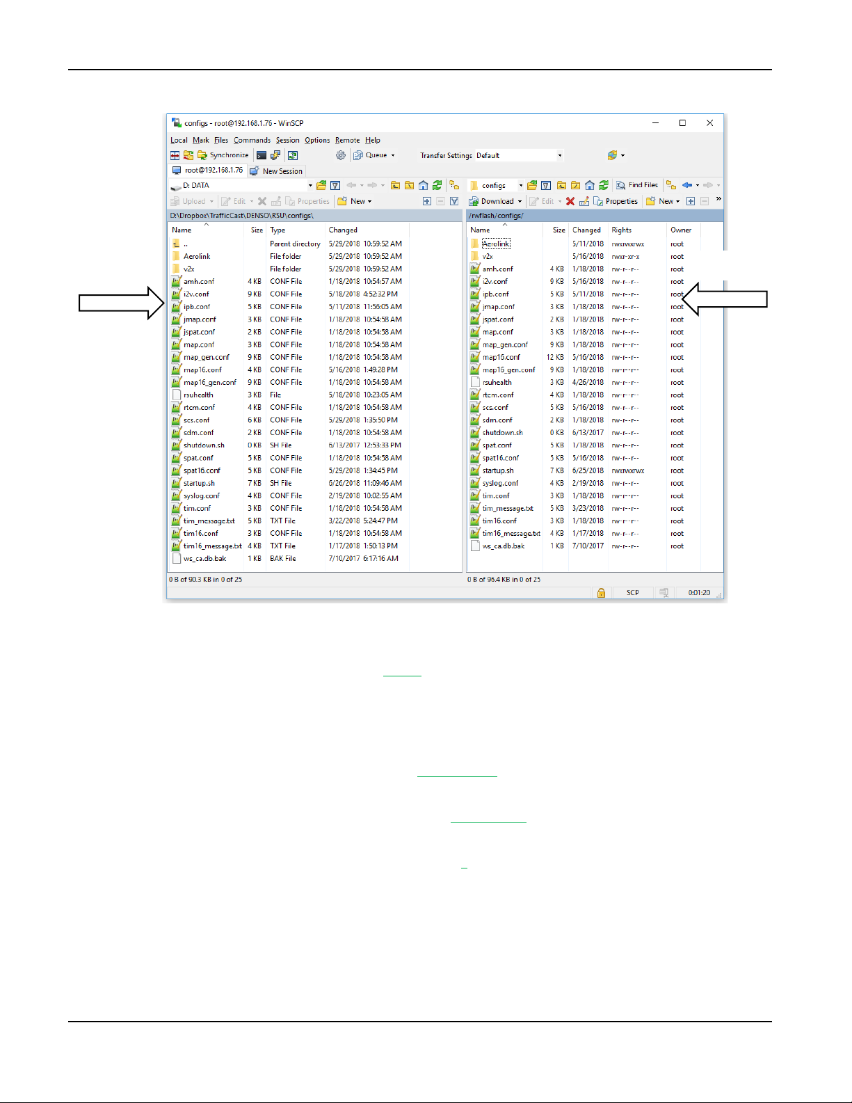
RSU Drive
4. Navigate the remote (right) window pane of WinSCP to the location /rwflash/configs/.
Local
Drive
5. Double-Click the map16.conf file to Open. This will set the Intersection ID for use by RSU.
a. Scroll to Line: IntersectionID = 53271 (Intersection ID generated by USDOT MAP
Creation software)
b. Close file, and Save
6. Double-Click the scs.conf file to Open. Identify the traffic controller network information.
a. Scroll to LocalSignalController IP = 192.168.1.32 (This is the traffic Controller’s IP
address)
b. Scroll to the LocalSignalControllerPort = 6053; 6053, 6054 (determined by the Agency’s
SPaT transmission “From/To” Ports)
c. Scroll to BypassSignalControllerNTCIP = 1; 0, 1 (Enables (1) bypassing NTCIP)
d. Close File and Save.
5-2 Revision 02 May 2019
TrafficCast Quick Start—BlueTOAD Spectra and Spectra RSU
Page 75
Appendix—How to Manually Configure a BlueTOAD Spectra RSU
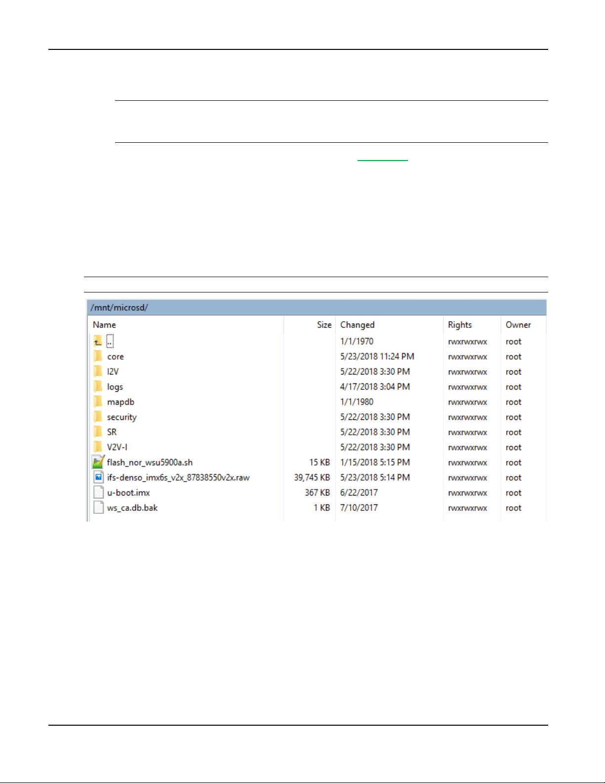
7. Double-Click the startup.sh file to Open. This will setup the network configuration for the RSU.
a. Scroll to export SCOIPADDRESS=192.168.1.76
Important: To be able to access the RSU in the future, make sure you keep a record of this
IP address! If you do NOT know the IP address, you will NOT be able to access the RSU,
and thus will have to perform a hard reset of the device!
b. Scroll to “Command”: route add -net 52.39.79.127 192.168.1.1
This adds a Static network route or bridge for remote communication with the RSU. This is
used by TrafficCast to forward SPaT, MAP and BSM messages to our Cloud.
How to Upload a MAP File
1. From the root directory, navigate to /mnt/microsd/I2V/amh.
2. Drag and drop the MAP file (map16_0x8002_intersectionID.txt) that was created for the RSU’s
intersection from your local drive to the amh folder.
Note: ONLY one (1) MAP (map16_0x8002_intersectionID.txt) file is allowed in the amh folder.
TrafficCast Quick Start—BlueTOAD Spectra and Spectra RSU
Revision 02 May 2019 5-3
Page 76

Appendix—How to Manually Configure a BlueTOAD Spectra RSU
3. Open PuTTY to start an SSH session into the RSU. Set the Host Name to [email protected], Port
to 22, Connection Type to SSH, and save the session as “DefaultRSU” for future use.
4. If prompted to accept the RSA key of the RSU click Yes.
5. Once the BASH shell is available, use the command “shutdown” to Restart and Apply the
configuration changes to the RSU.
TrafficCast Quick Start—BlueTOAD Spectra and Spectra RSU
5-4 Revision 02 May 2019
Page 77
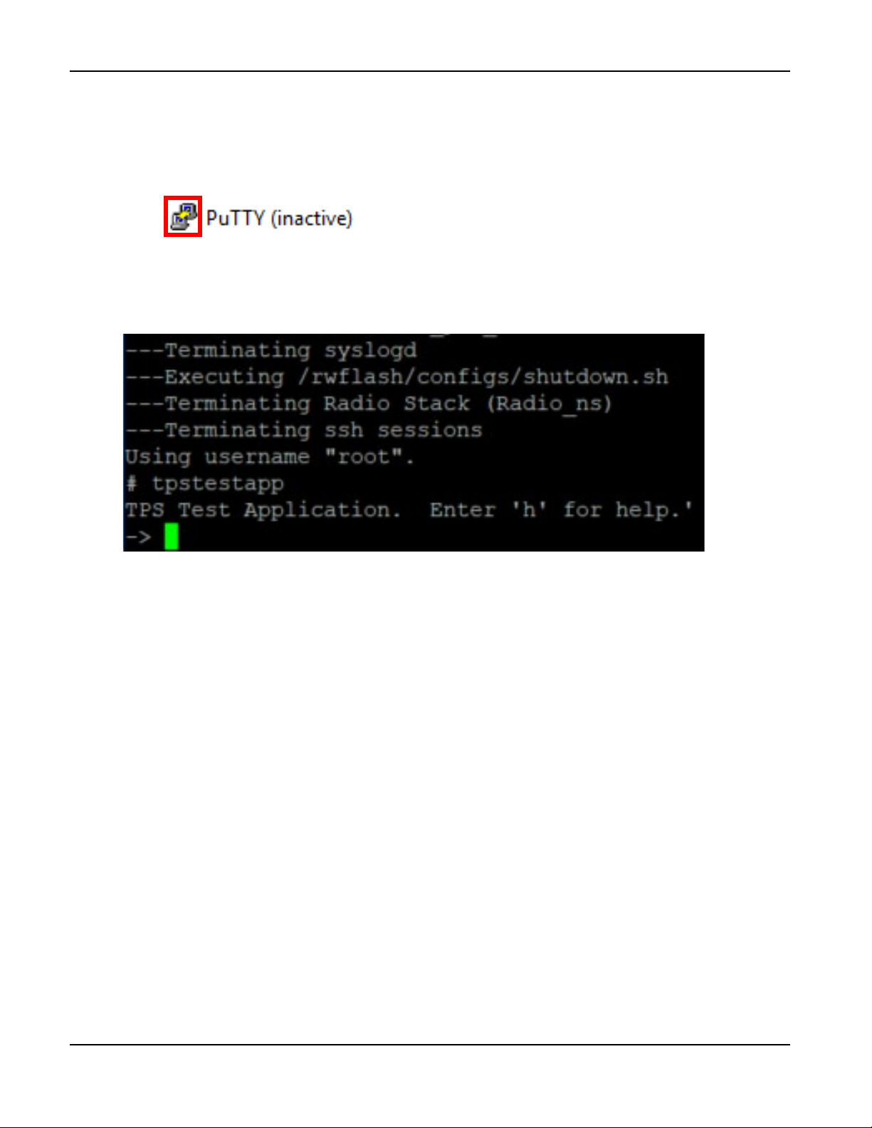
Appendix—How to Manually Configure a BlueTOAD Spectra RSU
Confirm that the BlueTOAD Spectra RSU is Broadcasting SPaT, MAP and BSM Data
6. Reconnect to the RSU:
a. Select the PuTTY icon on the upper left.
b. Select Restart Session
7. After you reconnect to the RSU, verify the GPS functionality:
a. Run “tpstestapp”
b. Press Enter
TrafficCast Quick Start—BlueTOAD Spectra and Spectra RSU
Revision 02 May 2019 5-5
Page 78
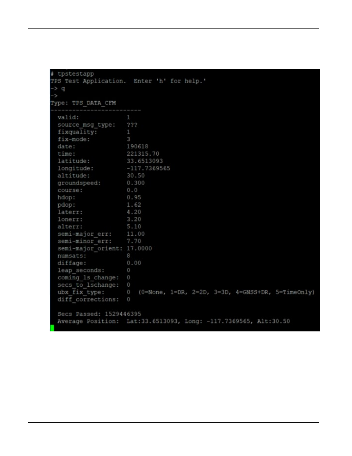
Appendix—How to Manually Configure a BlueTOAD Spectra RSU
8. To query the GPS status:
a. Press q
b. Press Enter
9. Check that the Average Position is being reported.
a. Press x
b. Press Enter
c. The BASH prompt is shown.
TrafficCast Quick Start—BlueTOAD Spectra and Spectra RSU
5-6 Revision 02 May 2019
Page 79
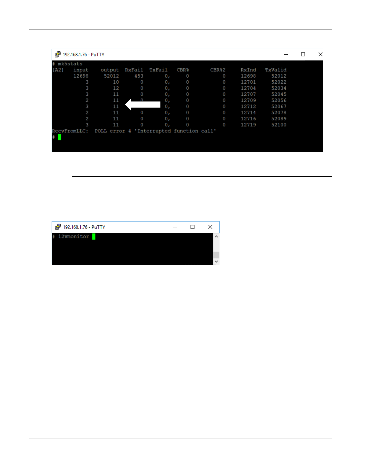
Appendix—How to Manually Configure a BlueTOAD Spectra RSU
10. Run “mk5stats” to verify the operation of the DSRC radio:
11. Each row indicates the number of DSRC messages received and sent per second. Verify that the
output column is sending an average of 11 messages per second.
Note: These 11 messages are the 10 SPaT messages plus 1 MAP message generated
by the RSU.
12. Press Ctrl-C to stop the mk5stats stream and return to the BASH prompt.
13. Run “i2vmonitor” to verify the decoding of the controller timing messages:
TrafficCast Quick Start—BlueTOAD Spectra and Spectra RSU
Revision 02 May 2019 5-7
Page 80

Appendix—How to Manually Configure a BlueTOAD Spectra RSU
For your notes:
TrafficCast Quick Start—BlueTOAD Spectra and Spectra RSU
5-8 Revision 02 May 2019
Page 81

6. Appendix—Blue TOAD Spectra RSU Specifications and Site Requirements Form
RSU Specifications
BlueTOAD Spectra RSU Network Security Statement
Currently the BlueTOAD Spectra RSU is designed to reside within the existing Traffic department network,
and thus will fall within its security policy structure and guidelines. For example:
• The BlueTOAD Spectra RSUs do not use public IPs, and thus are only accessible from inside the
same Agency Network. Relying on network switch/firewall settings, anyone from the outside would
have to enter by authorization from the Agency.
• RSUs are NOT connectable wirelessly via Wi-Fi or Bluetooth. Thus, wireless access from the street
is NOT possible. However, in the cabinet, wireline access is possible through the cabinet switch
and/or BlueTOAD PoE injector, but then once in the cabinet, access to other devices and the
Agency network is also vulnerable.
• The BlueTOAD Spectra Password can be changed using the TrafficCast Windows 10 based
BlueTOAD Spectra RSU Configuration Utility. The RSU side is then accessible with SSH on
Port 22 – currently using a “Root” login (Username), with a Password that can be changed based on
Agency requirements.
• Upon request, TrafficCast and DENSO can implement and test DSRC Security (IEEE 1609.2
Standard) to validate capability and interoperability of the BlueTOAD Spectra RSU to support
vehicle Onboard Unit (OBU) requests for the Security Certificate Management System (SCMS) to
provide exchange of OBU security certificates.
Bandwidth/Data Usage
Regarding the bandwidth, on a per RSU/site basis, between the controller and RSU expect 202 MB per day
of data going to the RSU. From the RSU to the TrafficCast servers (AWS) expect at least 450MB per day of
SPaT and MAP alone. Bluetooth data usage is 10-15 MB per day from the RSU to the TrafficCast servers.
Automotive Basic Safety Messages (BSM) will require additional bandwidth – but current enabled vehicle
population is too low to estimate data requirements.
FCC Individual Device RSU License Details
The TrafficCast BlueTOAD Spectra RSU includes a DSRC transceiver radio module manufactured by
DENSO International America, Inc. The TrafficCast RSU and DENSO OBUs comply with the FCC and
other technical requirements as prescribed by USDOT RSU Specification V4.1 Req_432-v004. In the past,
the TrafficCast RSU has received the FCC Grant of Equipment Authorization. The TrafficCast RSU
specifications for FCC authorization include:
• Manufacturer and model of the RSU Module - DEN
• SO RSU-5910A-2 Rev.1.1
• FCC ID numbers: 2AEGPMK5MOD / XPYTHEOP173
• Manufacturer and model of the Antenna - L-Comm HGV-4958-06U
• Antenna gain in dBi – 8 dBi max
• Antenna Beamwidth in degrees - Omni-directional (360 degree)
TrafficCast Quick Start—BlueTOAD Spectra and RSU
Revision 02 May 2019 6-1
Page 82
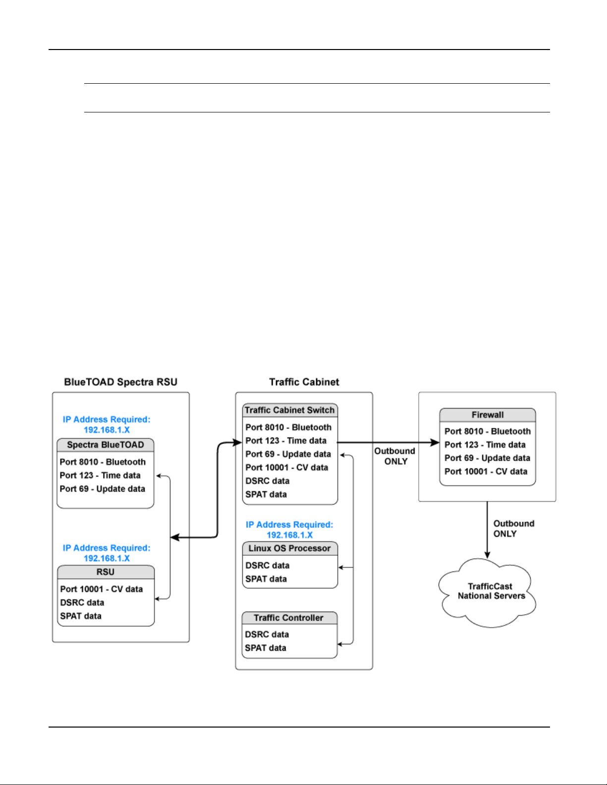
Appendix—Blue TOAD Spectra RSU Specifications and Site Requirements Form
Agency Servers - Firewall
• Center Line of the antenna Above Ground Level (AGL) in meters
Note: USDOT RSU Specification V4.1 Req_432-v004 references antenna centerline Mounting
Height of 8 Meters (26.3 Feet), not to exceed 15 meters (49.2 Feet) from the roadbed.
• RSU Equipment Class - C = 20 dBm Max. Output Power (400-meter communication zone)
• Effective Isotropic Radiated Power (EIRP) in dBm - 27.6dBm max for 33 dBm-rated channels;
22.6 dBm max for 23 dBm-rated channels (configuration parameters must be set correctly to reduce
max TX power on 23 dBm-rated channels)
• Operating channel numbers:
172 – 5855-5865MHz (Max EIRP = 33 dBm) (Public Safety)
174 – 5865-5875MHz (Max EIRP = 33 dBm)
176 – 5875-5885MHz (Max EIRP = 33 dBm)
178 – 5885-5895MHz (Max EIRP = 33 dBm) (Control Channel)
180 – 5895-5905MHz (Max EIRP = 23 dBm)
182 – 5905-5915MHz (Max EIRP = 23 dBm)
184 – 5915-5925MHz (Max EIRP = 33/40 dBm) (Government entities)
BlueTOAD Spectra RSU – Recommended Network Configuration Implementation
6-2 Revision 02 May 2019
TrafficCast Quick Start—BlueTOAD Spectra and Spectra RSU
Page 83
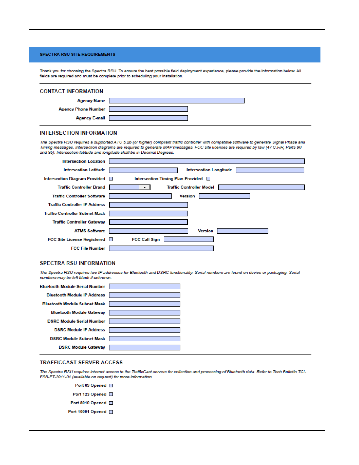
Appendix—Blue TOAD Spectra RSU Specifications and Site Requirements Form
BlueTOAD Spectra RSU Site Requirements Form
TrafficCast Quick Start—BlueTOAD Spectra and Spectra RSU
Revision 02 May 2019 6-3
Page 84

Appendix—Blue TOAD Spectra RSU Specifications and Site Requirements Form
For your notes:
TrafficCast Quick Start—BlueTOAD Spectra and Spectra RSU
6-4 Revision 02 May 2019
 Loading...