

Page 1
TracPhone® V3IP
User’s Guide
KVH Industries, Inc.
Page 2
TracPhone V3-IP
User’s Guide
This user’s guide provides all of the basic information you need to
operate, set up, troubleshoot, and maintain the TracPhone V3-IP
system. For detailed installation information, please refer to the
TracPhone V3-IP Installation Guide.
If you have any comments regarding this manual, please e-mail
them to [email protected]. Your input is greatly appreciated!
TracPhone V3-IP User’s Guide
Technical Support
Within the Continental U.S.A.:
Phone: 1 866 701-7103
E-mail: [email protected]
North/South America, Australia:
Phone: +1 401 851-3806
E-mail: [email protected]
Europe, Middle East, Asia, Africa:
Phone: +45 45 160 180
E-mail: [email protected]
KVH Part # 54-0890 Rev. B
© 2013, KVH Industries, Inc., All rights reserved.
Page 3

Trademark Information
TracPhone, KVH, CommBox, and the unique light-colored dome with dark contrasting baseplate
are trademarks of KVH Industries, Inc.
mini-VSAT Broadband is a service mark of KVH Industries, Inc.
ViaSat and the ViaSat logo are registered trademarks of ViaSat, Inc.
All other trademarks are the property of their respective owners.
Disclaimer
Every effort has been made to ensure the correctness and completeness of the material in this
document. No company shall be liable for errors contained herein. The information in this
document is subject to change without notice. No warranty of any kind is made with regard to
this material, including, but not limited to, the implied warranties of merchantability and fitness
for a particular purpose.
Page 4

Table of Contents
1 Introduction
About this Manual..............................................................................3
Who Should Use this Manual....................................................3
Icons Used in this Manual ........................................................3
Typographical Conventions ......................................................3
Related Documentation ............................................................4
Important Safety Information.............................................................5
TracPhone V3-IP User’s Guide
RF Radiation Hazard Area.........................................................6
System Overview ...............................................................................7
System Components.................................................................8
Satellite Communications ..................................................................9
Seamless Satellite Switching.................................................11
2 Getting Started
Service Activation ............................................................................15
Contacting the Satellite Airtime and Product
Activation Department............................................................15
Turning On the System ....................................................................16
System Startup ................................................................................17
Accessing the Web Interface ...........................................................18
Understanding the Home Page ........................................................19
Viewing the Help (User Documentation) ..........................................20
Clearing the Cache of Your Web Browser...............................21
i
Page 5

TracPhone V3-IP User’s Guide
3 Interface Preferences
4 No-Transmit Zones
Changing the Administrator Password ............................................25
Entering the Vessel Name................................................................26
Assigning the Phone Line Name ......................................................27
Adjusting the LCD Brightness ..........................................................28
No-Transmit Zones Overview...........................................................31
Status of No-Transmit Zones ...........................................................32
Establishing No-Transmit Zones......................................................33
Disabling No-Transmit Zones...........................................................35
Clearing No-Transmit Zones ............................................................36
5 Voice Connections
Voice Service Overview....................................................................39
How the Voice Service Works.................................................39
Making a Ship-to-Shore Call............................................................40
Making a Shore-to-Ship Call............................................................42
Virtual Numbers ...............................................................................43
VoiceMail .........................................................................................44
Recording a VoiceMail Personal Greeting...............................44
Listening to Your VoiceMail Messages...................................44
Faxing ..............................................................................................46
UCH-250 Fax Server ...............................................................47
Accessing Your Voice Account.........................................................48
6 Network Configuration
Wired DHCP Configuration ...............................................................51
Wireless DHCP Configuration...........................................................52
Wireless Settings on ICM........................................................53
ii
Page 6

TracPhone V3-IP User’s Guide
Configuring Computers for DHCP.....................................................55
Windows 8 DHCP Settings......................................................55
Windows 7 or Windows Vista DHCP Settings ......................... 56
Windows XP DHCP Settings ...................................................57
Mac OS X DHCP Settings........................................................59
Static IP Configuration..................................................................... 60
LAN Settings on ICM ........................................................................ 63
Cache Settings on ICM.....................................................................65
Physical Ethernet Port Configurations .............................................66
Static IP Port Configuration .................................................... 67
Dual Dome Port Configuration................................................68
Legacy Port Configuration......................................................69
CommBox Settings on ICM ..............................................................70
Reset to Factory Configuration ........................................................71
7 Data Connections
Internet Access Overview ................................................................ 75
Connecting to the Internet......................................................75
Tips for Minimizing Data Usage.......................................................76
Preventing Automatic Updates...............................................77
Disabling Automatic File Backup and Synchronization.......... 77
Firewall Protection .................................................................78
Web Browser Settings............................................................ 78
Data-Intensive Applications ...................................................79
Mobile Websites.....................................................................79
Disabling Wi-Fi Access on Mobile Devices.............................79
E-mail Best Practices.............................................................80
CommBox Features .........................................................................81
Accessing the CommBox Web Interface ................................81
iii
Page 7

TracPhone V3-IP User’s Guide
8 Troubleshooting
Initial Steps for Any Problem ...........................................................85
Troubleshooting a Voice Problem ....................................................87
Troubleshooting a Data Problem......................................................89
Error Messages................................................................................91
Status Information ...........................................................................94
Status Information on the Web Interface................................94
Status Information on the ICM Front Panel LCD ...................100
LED Indicators................................................................................104
System Logs ..................................................................................106
Operational Log ....................................................................106
Event Log..............................................................................107
Equipment ID Numbers ..................................................................108
Software Versions..........................................................................109
Technical Support..........................................................................110
9 Maintenance
Preventive Maintenance ................................................................113
Software Updates ..........................................................................114
Using the ICM to Update Software........................................115
Using Your Computer to Update Software............................116
Using an iPhone/iPod touch to Update Software..................117
Using a USB Flash Drive to Update Software .......................118
Modem Configuration Updates ......................................................119
Manually Updating the Modem Configuration Files..............120
Corrective Maintenance.................................................................124
Gyro Calibration .............................................................................125
Hardware Restart...........................................................................127
iv
Page 8

TracPhone V3-IP User’s Guide
A Wiring Diagram
Wiring Diagram..............................................................................131
B LCD Menus
LCD Menus Quick Reference Guide ...............................................135
CSpecifications
System Specifications ...................................................................139
D Glossary
Glossary.........................................................................................143
E Index
Index..............................................................................................157
v
Page 9

1. Introduction
This section provides important safety information you need to know
before using the system. It also provides a basic overview of the system
and satellite communications.
Contents
About this Manual.............................................................. 3
Important Safety Information ............................................ 5
System Overview............................................................... 7
Satellite Communications.................................................. 9
TracPhone V3-IP User’s Guide
Introduction
1
Page 10
About this Manual
This manual provides complete operation, configuration, and
troubleshooting information for the TracPhone V3-IP system.
Who Should Use this Manual
The user should refer to this manual to learn how to operate the
system, configure all aspects of the system, and identify the cause of
any problem.
The installer should refer to this manual for information on setting up
the system for the user’s desired preferences.
The servicing technician should refer to this manual to help identify
the cause of a system problem.
TracPhone V3-IP User’s Guide
Introduction
Icons Used in this Manual
This manual uses the following icon:
Icon Description
This is a danger, warning, or caution notice. Be sure
to read these carefully to avoid injury!
Typographical Conventions
This manual uses the following typographical conventions:
Text Example Description
Press MENUS to view the
menu.
At the confirmation
message, click Save.
SELECT SATELLITES Text as it appears on the ICM display
Name of ICM buttons
Element of a graphical user interface
See “Using this Manual”
on page 3.
Visit www.kvh.com/
mvbservice for details.
Cross-reference to another chapter in
the manual
Cross-reference to a website
3
Page 11

TracPhone V3-IP User’s Guide
Introduction
Related Documentation
In addition to this User’s Guide, the following documents are
provided with your TracPhone system:
Document Description
Installation Guide Complete installation instructions
Quick Start Guide Handy quick reference guide with
Activation Checklist Details on activating the system for
Installation Checklist Form that the installer must return to
basic operating instructions
mini-VSAT Broadband service
validate the quality of the installation
Antenna Mounting
Template
Template that the installer uses to lay
out the antenna mounting holes
Warranty Statement Warranty terms and conditions
Kitpack Contents List List of every part supplied in the kit
4
Page 12
Important Safety Information
For your own safety, and for the safety of your passengers and/or
crew, be sure to read the following important notices.
WARNING
Risk of Electric Shock
Potentially lethal voltages are present within the ICM. To avoid
electric shock, do not open the chassis enclosure.
WARNING
Risk of Electric Shock
If any component of the TracPhone system becomes damaged and/
or no longer functions normally, disconnect it from vessel power,
secure it from unintended operation, and contact KVH Technical
Support (see “Technical Support” on page 110). All repairs or
modifications must be performed by a trained, KVH-certified
technician.
TracPhone V3-IP User’s Guide
Introduction
WARNING
Risk of Explosion
Do not operate the ICM (or any other electrical device) in an
environment where flammable gases, vapors, or dusts are present.
WARNING
Risk of Electric Shock
Failure to ground the TracPhone system properly to ship’s ground
will cause an unsafe floating ground condition, risking potentially
lethal electric shock. Refer to the Installation Guide for details on
the proper grounding of the equipment.
5
Page 13

TracPhone V3-IP User’s Guide
Radiation
Hazard
32
f
t
(
10
m)
7.5°
Radiation
Hazard
32 ft (10 m)
75°75°
7.5°
Antenna
Introduction
RF Radiation Hazard
The antenna transmits up to 3 watts of radio frequency (RF) energy
that is potentially harmful. Whenever the system is powered on,
make sure everyone stays more than 32 feet (10 m) away from the
antenna. No hazard exists directly below the antenna.
RF Radiation Hazard Area
Since a person above deck may not know which direction the antenna
is pointing, you should always observe the minimum safe distance to
prevent RF radiation exposure. Within the antenna’s elevation range,
the minimum safe distance is 32 feet (10 m). No hazard exists directly
below the antenna.
CAUTION
Figure 1-1 Minimum Safe Distance to Avoid Risk of RF Radiation Exposure
NOTE: You can set up no-transmit zones to inhibit transmissions within
areas frequented by passengers and/or crew. See “Establishing No-Transmit
Zones” on page 33 for details.
6
Page 14

System Overview
Your TracPhone V3-IP is a complete mini-VSAT Broadband
communications system for mariners on the move. Using cutting-edge
CRMA (code reuse multiple access) and spread spectrum
technologies, the TracPhone V3-IP delivers a seamless and consistent
Internet experience. And it all comes with an antenna that is smaller
and lighter than traditional VSAT antennas.
The system consists of an antenna and Integrated CommBox Modem
(ICM) that connect to a land-based hub via a Ku-band satellite. The
hub, managed by a Network Operations Center (NOC), then provides
the link to the Internet and the terrestrial telephone network.
NOTE: A detailed wiring diagram is provided in “Wiring Diagram” on
page 131.
TracPhone V3-IP User’s Guide
Introduction
Figure 1-2 TracPhone V3-IP mini-VSAT Broadband Network Diagram
Ku-band Satellite
mini-VSAT Broadband
Connection
TracPhone
Antenna
Integrated CommBox
Modem (ICM)
Internet
VoIP ConnectionEthernet Connection
Customer-Supplied
Customer-Supplied
Hub
Telephone
Network
Computer(s)
Analog Phone
7
Page 15
TracPhone V3-IP User’s Guide
Introduction
System Components
The TracPhone V3-IP system includes the following components:
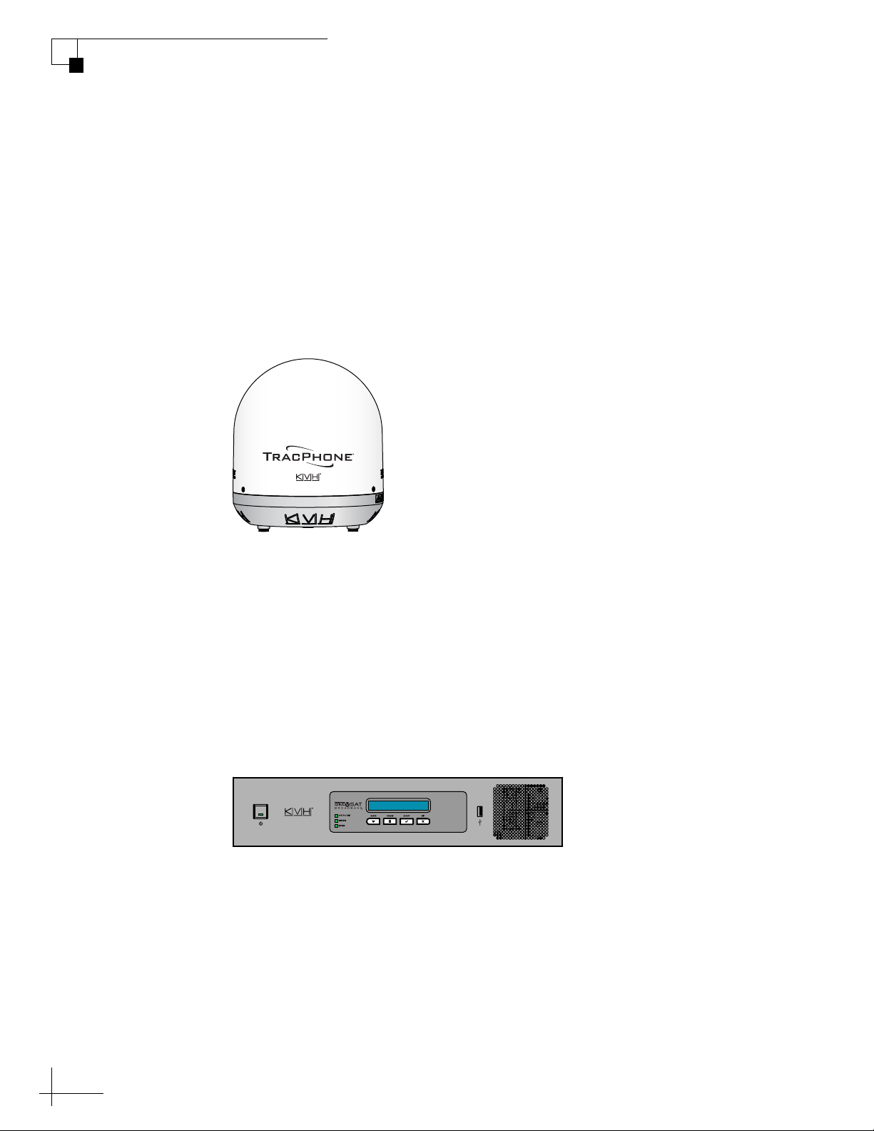
Antenna Unit
The antenna unit provides the satellite link to the land-based hub.
Using its integrated GPS, advanced reflector technology, and gyro
stabilization, the antenna automatically locates and tracks the correct
satellite, even while your vessel is on the move.
Figure 1-3 Antenna Unit
Integrated CommBox Modem (ICM)
The ICM is the transceiver and “brain” of the system. Its built-in
modem processes all incoming and outgoing data traffic using its
proprietary spread spectrum technologies. Its built-in router and
wireless access point (WAP) provide the connection to your onboard
local area network (LAN). And its easy-to-use web interface and front
panel LCD allow you to operate and configure all aspects of the
system.
Figure 1-4 ICM
8
Page 16

Satellite Communications
Equator
Communications satellites are located in fixed positions above the
Earth’s equator and relay data to/from the earth within the regions
that they serve. Therefore, to communicate via a given satellite, you
must be located within that satellite’s unique coverage area, also
known as its “footprint.”
To view the latest mini-VSAT Broadband satellite coverage map, visit
KVH’s website at www.kvh.com/minivsatmap. The map is an
amalgamation of all of the individual satellites’ coverage areas.
Figure 1-5 Example of a Satellite Footprint
TracPhone V3-IP User’s Guide
Introduction
9
Page 17
TracPhone V3-IP User’s Guide
Blocked!
Introduction
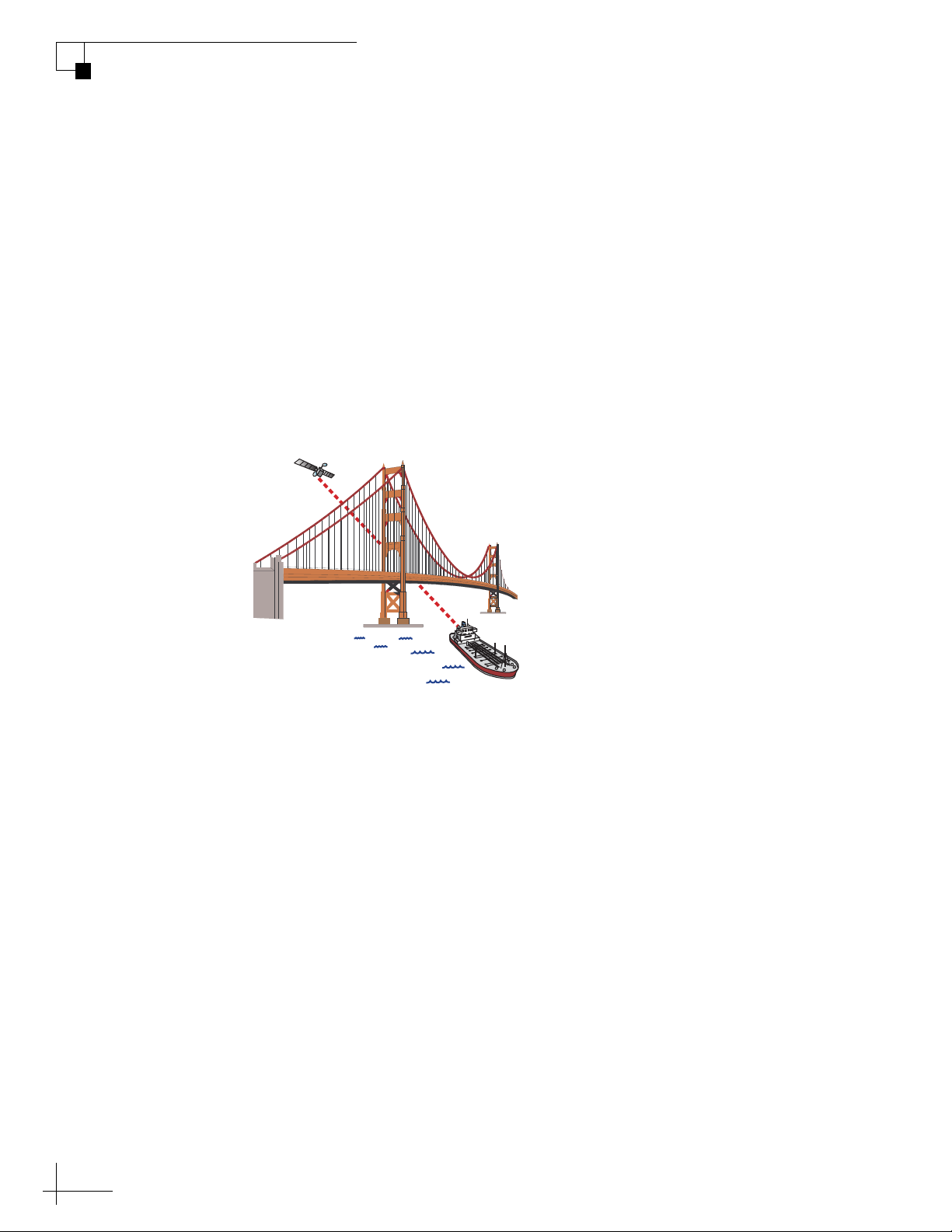
In addition, since satellites are located 22,300 miles (35,900 km) above
the equator, the TracPhone antenna must have a clear view of the sky
to transmit and receive signals. Anything that stands between the
antenna and the satellite can block signals, resulting in lost data.
Common causes of blockage include the following:
• Trees, buildings, and bridges
• Other vessels docked alongside your vessel
• Onboard masts, antennas, or other structures
• Inclement weather conditions
Figure 1-6 Example of Satellite Blockage
10
Page 18
Seamless Satellite Switching
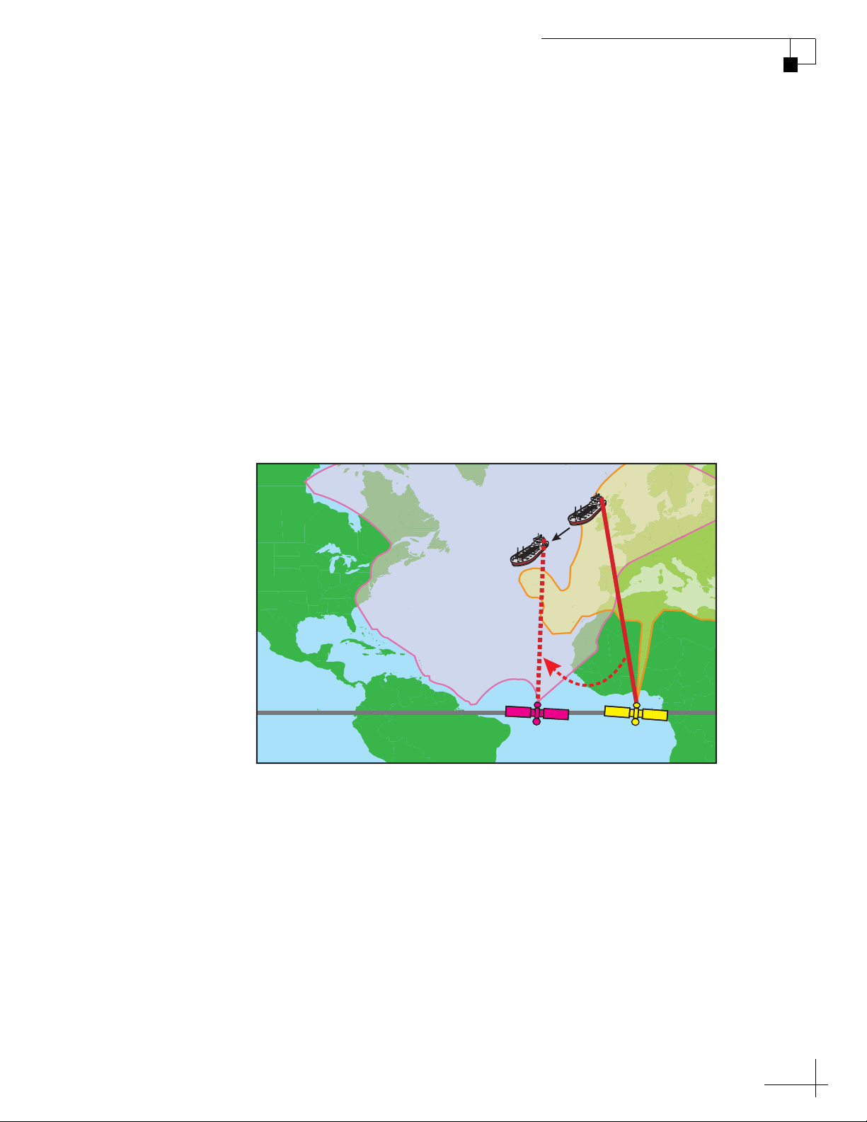
The high-traffic regions of the global mini-VSAT Broadband coverage
area are covered by more than one satellite. The ICM’s built-in modem
maintains a prioritized list of all satellites in the network and selects
the highest priority satellite that provides coverage at the vessel’s
current GPS location. If the antenna is unable to track the chosen
satellite for any reason (due to a blockage condition, for example), the
modem selects the next available satellite on the list and the antenna
automatically switches to that satellite
In addition, whenever the vessel travels outside the boundary of the
current satellite’s coverage area, the modem selects the highest
priority satellite in the adjoining region and the antenna automatically
switches to that satellite to maintain the service connection.
Figure 1-7 Example of Automatic Satellite Switching
TracPhone V3-IP User’s Guide
Introduction
Antenna switches satellites
when vessel passes into
the next coverage area
mini-VSAT Broadband
Satellites
NOTE: The coverage areas shown here are for illustration purposes only.
They do not represent boundaries of actual coverage areas.
11
Page 19

2. Getting Started
This section explains how to activate the TracPhone system for miniVSAT Broadband service. It also explains how to turn on the system for
the first time and how to interpret the system’s startup screens. Then it
introduces the TracPhone V3-IP web interface, detailing how to access
the Home page and the Help documentation.
Contents
Service Activation............................................................ 15
Turning On the System .................................................... 16
System Startup................................................................ 17
TracPhone V3-IP User’s Guide
Getting Started
Accessing the Web Interface........................................... 18
Understanding the Home Page........................................ 19
Viewing the Help (User Documentation).......................... 20
13
Page 20

Service Activation
Before you can start using the TracPhone system, you need to activate
it for mini-VSAT Broadband service. To activate, fill out and submit
the appropriate form(s) available at www.kvh.com/mvbservice.
NOTE: You will need to enter the antenna and ICM serial numbers on the
form. You can find these numbers on the Support page of the TracPhone V3IP web interface or in the System Info LCD menu on the ICM’s front panel.
See “Equipment ID Numbers” on page 108.
Fax or e-mail the completed form(s) to KVH:
Fax: +1 401 851-3823
E-mail: [email protected]
Once KVH processes the form(s), activates your account, and registers
your product, you will receive an e-mail with the details of your new
service, including your vessel’s phone number.
TracPhone V3-IP User’s Guide
Getting Started
Contacting the Satellite Airtime and Product Activation Department
If you have any questions, or would like to make a change to your
account, please contact KVH’s Satellite Airtime & Product Activation
Department via e-mail at [email protected] or by phone at:
Region Phone Number
Europe & Middle East +45 45 160 197
North & South America +1 401.847.3327
Asia +65 31584084
U.S. & Canada 866.399.8509 (toll-free)
15
Page 21
TracPhone V3-IP User’s Guide
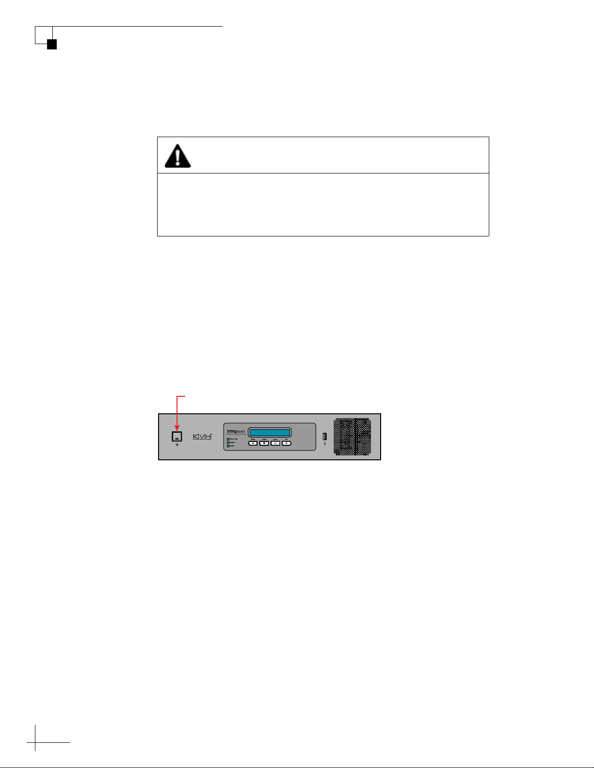
Power Button
ICM
Getting Started
Turning On the System
To turn on your TracPhone system, follow these steps:
CAUTION
The antenna transmits RF energy that is potentially harmful. Make
sure everyone stays more than 32 feet (10 m) away from the
antenna while it is in use. No hazard exists directly above the
antenna and anywhere below its mounting plane.
1. Make sure the antenna has a clear, unobstructed view of the
sky.
2. Make sure vessel AC power is applied to the ICM and your
computer(s).
3. Press the power button on the front of the ICM. The button’s
light should illuminate green.
Figure 2-1 Power Button
4. Wait five minutes for system startup.
5. Turn on your computer(s) that are connected to the network.
Once the antenna finds the service satellite and the ICM’s
modem logs into the mini-VSAT Broadband service, all status
lights on the ICM should be lit green. If any lights are not lit
green, refer to “LED Indicators” on page 104.
16
Page 22

System Startup
The ICM shows the following screens during startup. Similar
messages will also appear on the web interface. If the display shows an
error message, see “Error Messages” on page 91.
ICM Screen Description
TracPhone V3-IP User’s Guide
Getting Started
ICM
INITIALIZING...59
NO-TRANSMIT ZONE 1
AZ RANGE: 335-025
ANTENNA READY
WAITING FOR MODEM
MODEM COMMS: OK The ICM’s modem is
WAITING FOR GPS The antenna is waiting for a GPS
GPS: ACQUIRED
41.5198N, 123.5817W
RECEIVING SATELLITE
INFO FROM MODEM
The system is running a self test
routine
Displays the azimuth ranges of
any user-configured no-transmit
zones
The antenna is waiting for the
ICM’s modem to initialize
communicating OK
fix
When GPS acquires a fix,
momentarily displays your
latitude/longitude
The ICM’s modem is providing
satellite identification data to the
antenna
ANTENNA STATE
INITIALIZING
SEARCHING FOR 105.0W
SATELLITE
RF RADIATION HAZARD!
TRANSMIT INHIBITED
OFFLINE
TRACKING 105.0W
ONLINE
TRACKING 105.0W
The antenna is initializing
The antenna is searching for the
mini-VSAT Broadband satellite
If the antenna is pointing within
an enabled no-transmit zone, it
will not transmit
The antenna is now tracking the
satellite
The ICM’s modem has accessed
the mini-VSAT Broadband
service; the system is ready for
use!
17
Page 23
TracPhone V3-IP User’s Guide
Getting Started
Accessing the Web Interface
The ICM offers a local web interface, which you can use to check
system status, update software, and configure all aspects of the
system. To access the web interface, simply open a web browser
window on any computer on the network and enter the following web
address:
http://minivsat.kvh
NOTE: This web address may not work on all platforms and browsers. It also
will not work in certain network configurations. If the web interface does not
appear, enter the ICM’s IP address instead (default is 192.168.5.1). You can
find this address on the ICM front panel LCD (go to Settings > Network
Settings > IP Assignments).
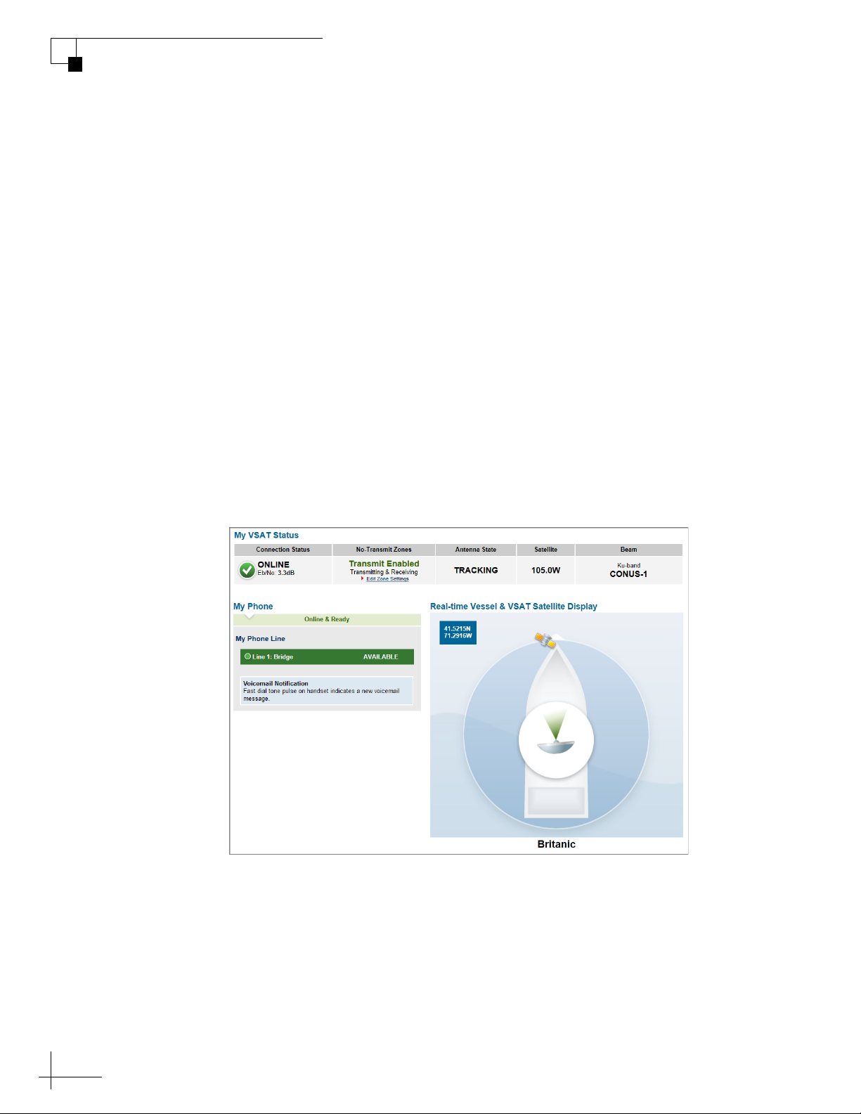
As long as the ICM is turned on and functioning properly, the Home
page will appear in your browser.
Figure 2-2 Web Interface Home Page
18
Page 24
Understanding the Home Page
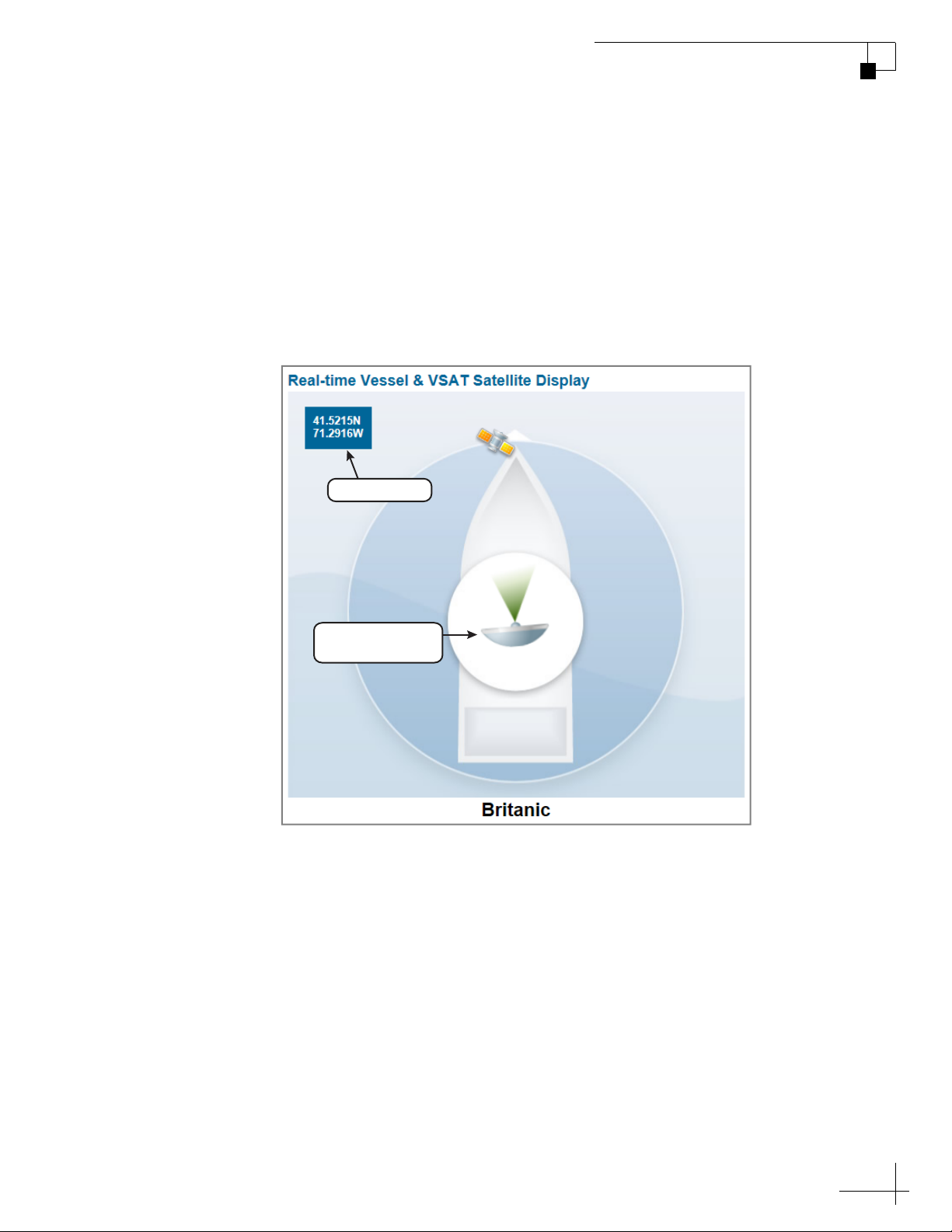
The Home page of the TracPhone V3-IP web interface provides
essential system status information, including the status of the
antenna, the system’s connection to the mini-VSAT Broadband service,
and the voice service connection. It also displays the vessel’s GPS
position and provides a graphical representation of the antenna’s
pointing direction relative to the bow of the vessel.
Figure 2-3 Real-time Vessel & VSAT Satellite Display
GPS Position
TracPhone V3-IP User’s Guide
Getting Started
Antenna Pointing
Direction
19
Page 25
TracPhone V3-IP User’s Guide
Getting Started
Viewing the Help (User Documentation)
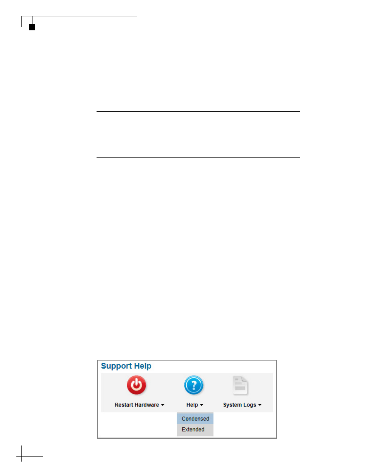
The system’s Help is available on the Support page of the TracPhone
V3-IP web interface. Two options are offered: Condensed and
Extended. Refer to either of these resources for answers to your
operation, configuration, or troubleshooting questions.
Important!
You might need to clear your web browser’s cache in order to view
the latest version of the Help. See “Clearing the Cache of Your Web
Browser” on page 21 for details.
NOTE: The Help is compatible with the following web browsers: Internet
Explorer, Mozilla Firefox, Google Chrome, and Apple Safari. If you are using
Internet Explorer version 10, you will first need to adjust the width of the
Help’s navigation pane to view topics due to a known software issue.
Condensed Help
• Resides on the ICM locally
•Text-only format
Extended Help
• Resides on the KVH website (airtime charges may apply)
• Media-rich format, complete with images and tutorials
To access either of these resources from the ICM, follow these steps:
1. At the TracPhone V3-IP web interface, click the Support tab.
2. On the Help menu, click the desired option.
Figure 2-4 Help Options
20
Page 26
Clearing the Cache of Your Web Browser
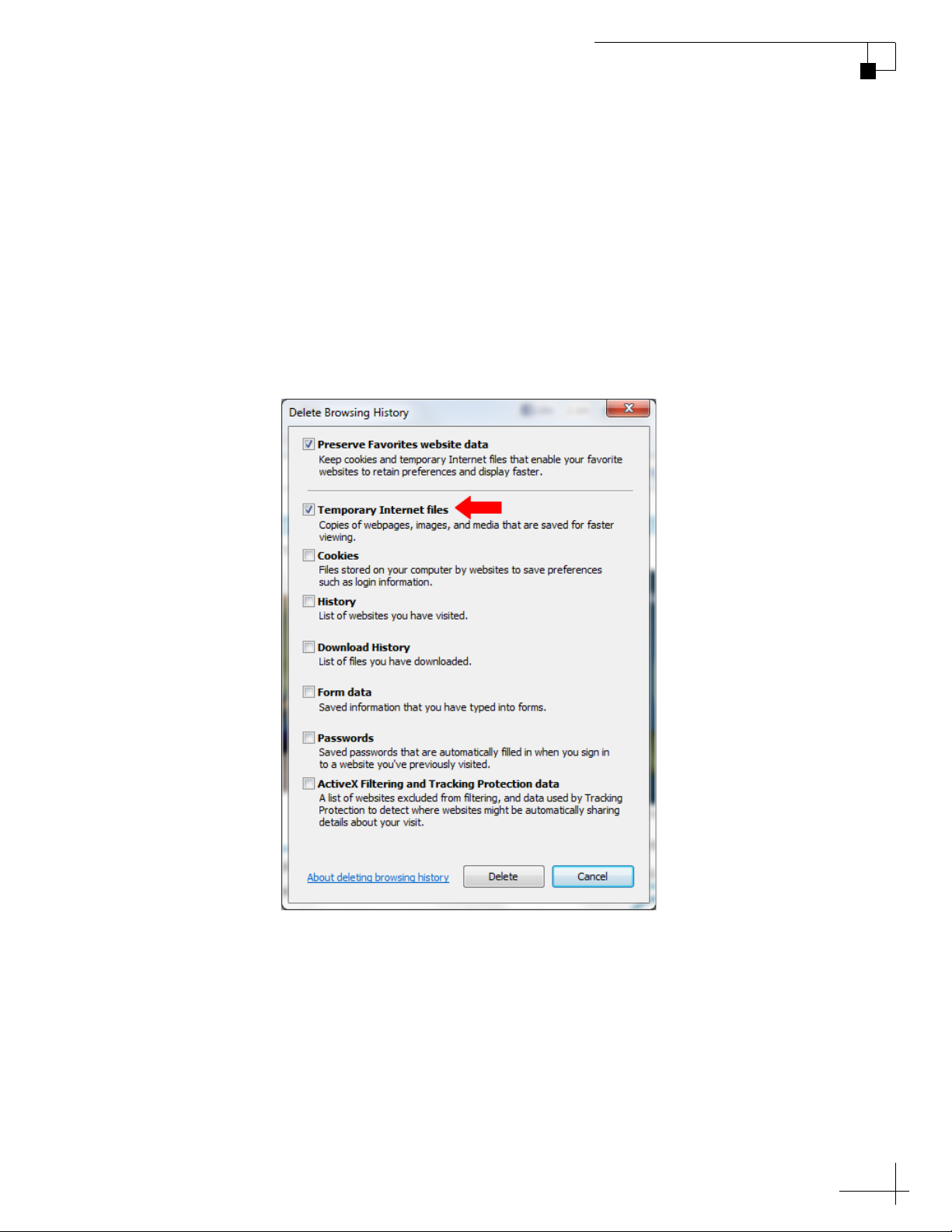
When you visit a web page, your browser may store a copy of it in its
local cache. As a result, when you revisit the page, the browser may
display the old copy it had previously stored rather than reload the
latest version from the web. Since the Help actually consists of a set of
web pages, you might need to clear your web browser’s cache to force
it to load the latest version. For example, in Internet Explorer, go to
Tools > Safety > Delete Browsing History (or press Ctrl + Shift + Del),
select Temporary Internet files, then click Delete.
Figure 2-5 Clearing the Cache in Internet Explorer
TracPhone V3-IP User’s Guide
Getting Started
21
Page 27

TracPhone V3-IP User’s Guide
Interface Preferences
3. Interface Preferences
This section explains how to customize the TracPhone V3-IP web
interface by entering the names of the vessel and phone line. It also
explains how to change the Administrator password and adjust the
brightness of the ICM’s front panel LCD.
Contents
Changing the Administrator Password ............................ 25
Entering the Vessel Name ............................................... 26
Assigning the Phone Line Name...................................... 27
Adjusting the LCD Brightness.......................................... 28
23
Page 28
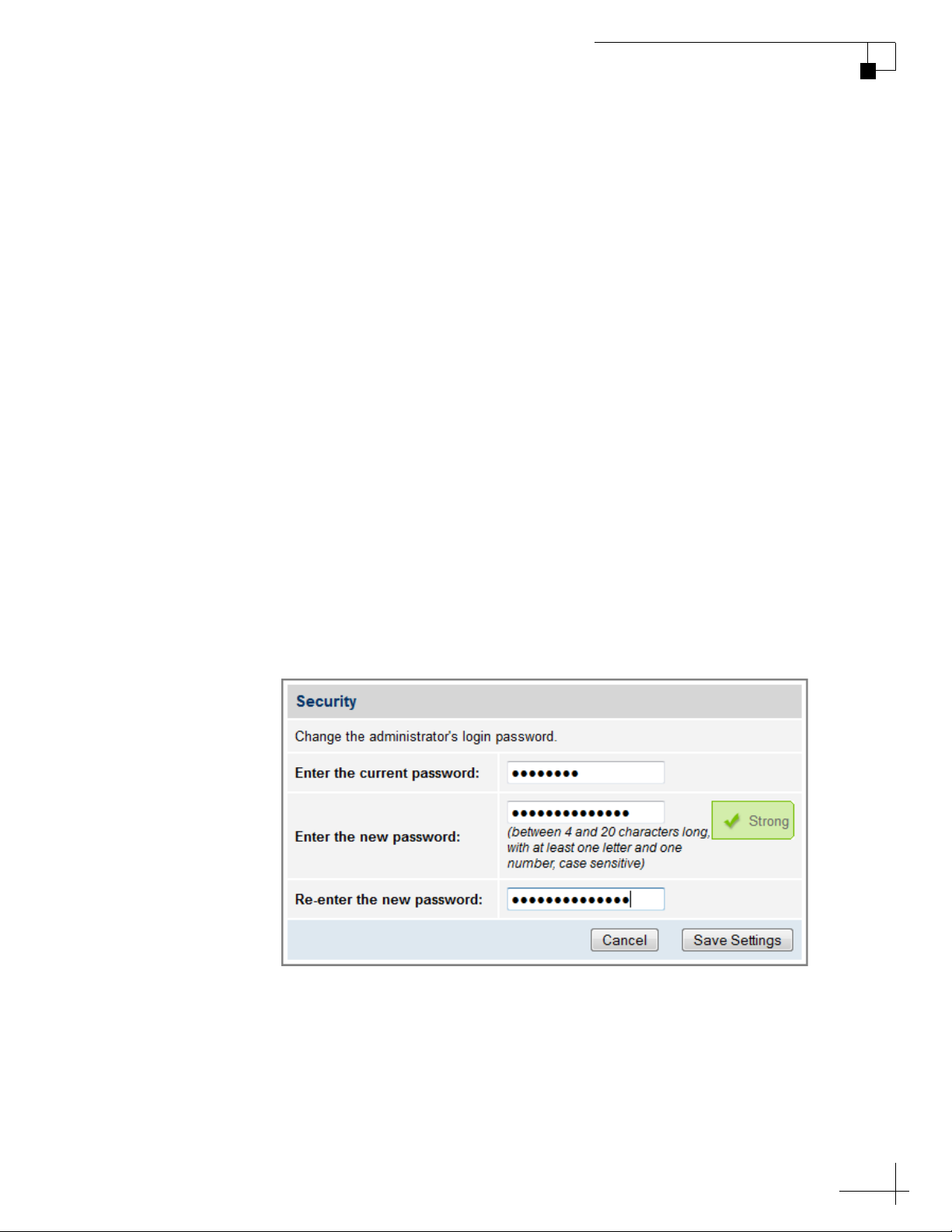
Changing the Administrator Password
You must be logged in as an Administrator to make any substantial
changes to the system’s configuration on the TracPhone V3-IP web
interface. To prevent unauthorized user access, KVH recommends that
you change the Administrator password to something unique.
To change the Administrator password, follow these steps:
1. At the TracPhone V3-IP web interface, click the Settings tab.
Then click Account.
2. In Security, click Edit.
3. Enter the current password. If the password has never been
changed, enter the default password: “password”.
TracPhone V3-IP User’s Guide
Interface Preferences
NOTE: The password must be between 4 and 20 characters in length, with at
least one letter and one number, case-sensitive.
4. Enter and then re-enter your new password.
5. Click Save Settings.
Figure 3-1 Changing the Administrator Password
25
Page 29
TracPhone V3-IP User’s Guide
Interface Preferences
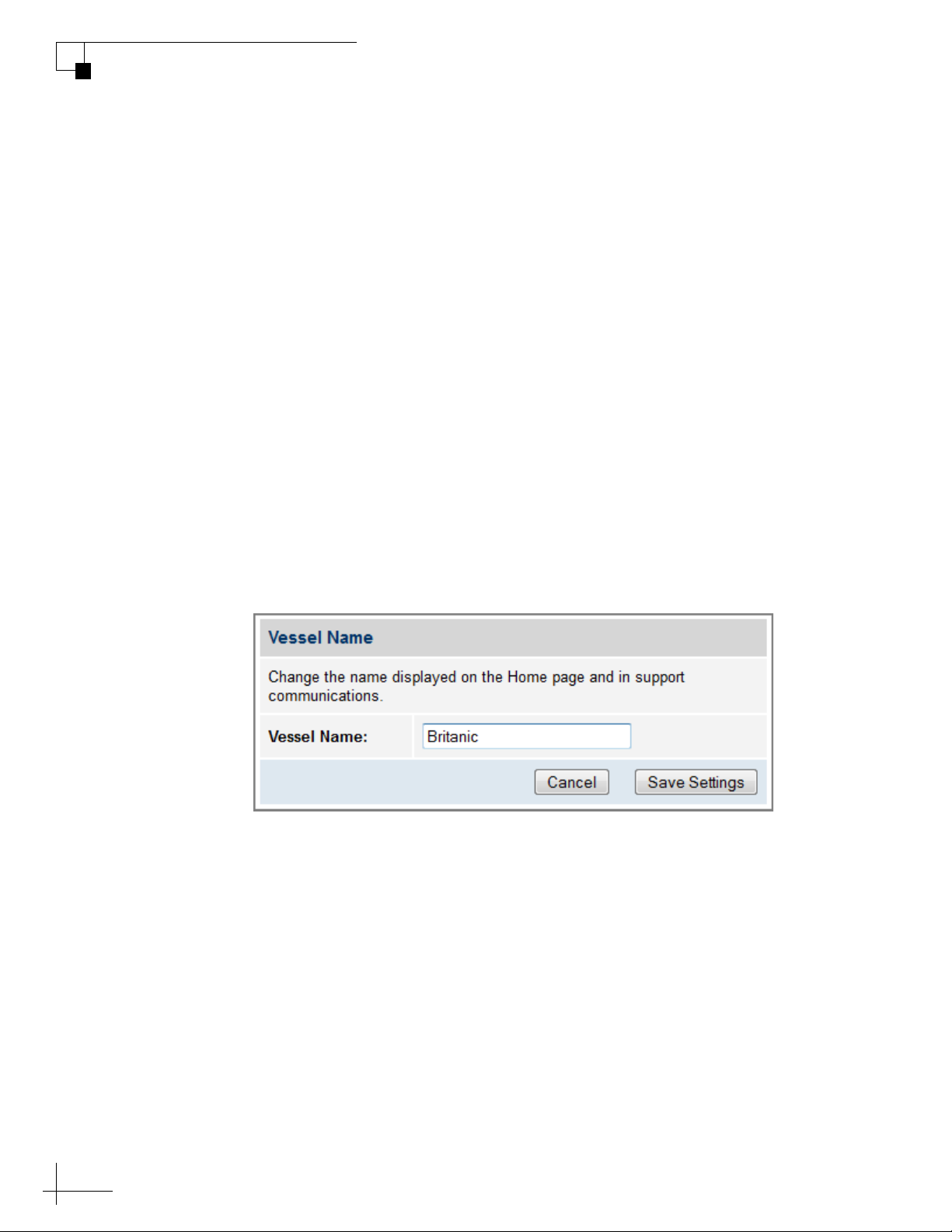
Entering the Vessel Name
The vessel name is displayed on the Home page of the TracPhone V3IP web interface. It also appears in all technical support
communications.
To enter your vessel’s name in the TracPhone V3-IP web interface,
follow these steps:
1. At the TracPhone V3-IP web interface, click the Settings tab.
Then click Account.
2. In Vessel Name, click Edit.
3. If the Login window appears, log in with the Administrator
password.
4. Enter your vessel’s name.
5. Click Save Settings.
Figure 3-2 Entering the Vessel Name
26
Page 30

Assigning the Phone Line Name
The phone line name is displayed on the Home page of the TracPhone
V3-IP web interface. It also appears in all technical support
communications. For example, you might assign the name “Bridge.”
To assign a name to the phone line, follow these steps:
1. At the TracPhone V3-IP web interface, click the Settings tab.
Then click Other.
2. In Phone Line Name, click Edit.
3. If the Login window appears, log in with the Administrator
password.
4. Enter a name for Line 1.
TracPhone V3-IP User’s Guide
Interface Preferences
5. Click Save.
Figure 3-3 Assigning the Phone Line Name
27
Page 31
TracPhone V3-IP User’s Guide
SETTINGS
NEXT SELECT EXIT
SYSTEM SETTINGS
NEXT SELECT EXIT
LCD BRIGHTNESS
SELECT EXIT
BRIGHTNESS=HIGH
NEXT SELECT EXIT
BRIGHTNESS=MEDIUM?
NEXT SELECT EXIT
Press MENUS until
the desired setting is
displayed: HIGH,
MEDIUM, or LOW.
Press MENUS until
SETTINGS is displayed.
Interface Preferences
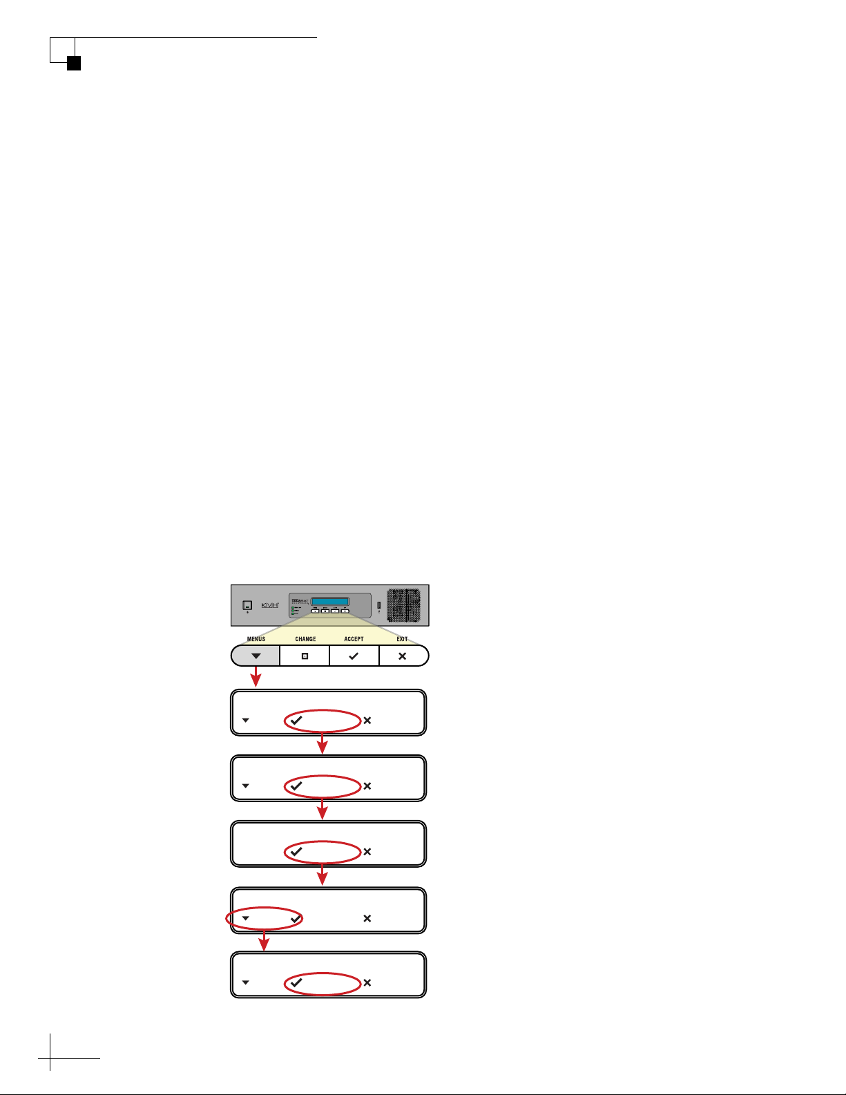
Adjusting the LCD Brightness
You can adjust the brightness of the ICM’s front panel LCD to suit
your preferences.
To adjust the brightness of the ICM’s display, follow these steps:
1. At the ICM front panel, press MENUS until the display shows
“SETTINGS.”
2. Press ACCEPT.
3. At “SYSTEM SETTINGS,” press ACCEPT.
4. At “LCD BRIGHTNESS,” press ACCEPT.
5. Press MENUS until the display shows the desired brightness
setting: HIGH, MEDIUM, or LOW.
6. Press ACCEPT.
7. Press EXIT to exit the menu.
Figure 3-4 LCD Brightness Setting
28
Page 32

TracPhone V3-IP User’s Guide
No-Transmit Zones
4. No-Transmit Zones
This section explains how to view, configure, temporarily disable, and
clear no-transmit zones, which prohibit the antenna from transmitting
within a certain azimuth range.
Contents
No-Transmit Zones Overview .......................................... 31
Status of No-Transmit Zones........................................... 32
Establishing No-Transmit Zones...................................... 33
Disabling No-Transmit Zones .......................................... 35
Clearing No-Transmit Zones............................................ 36
29
Page 33
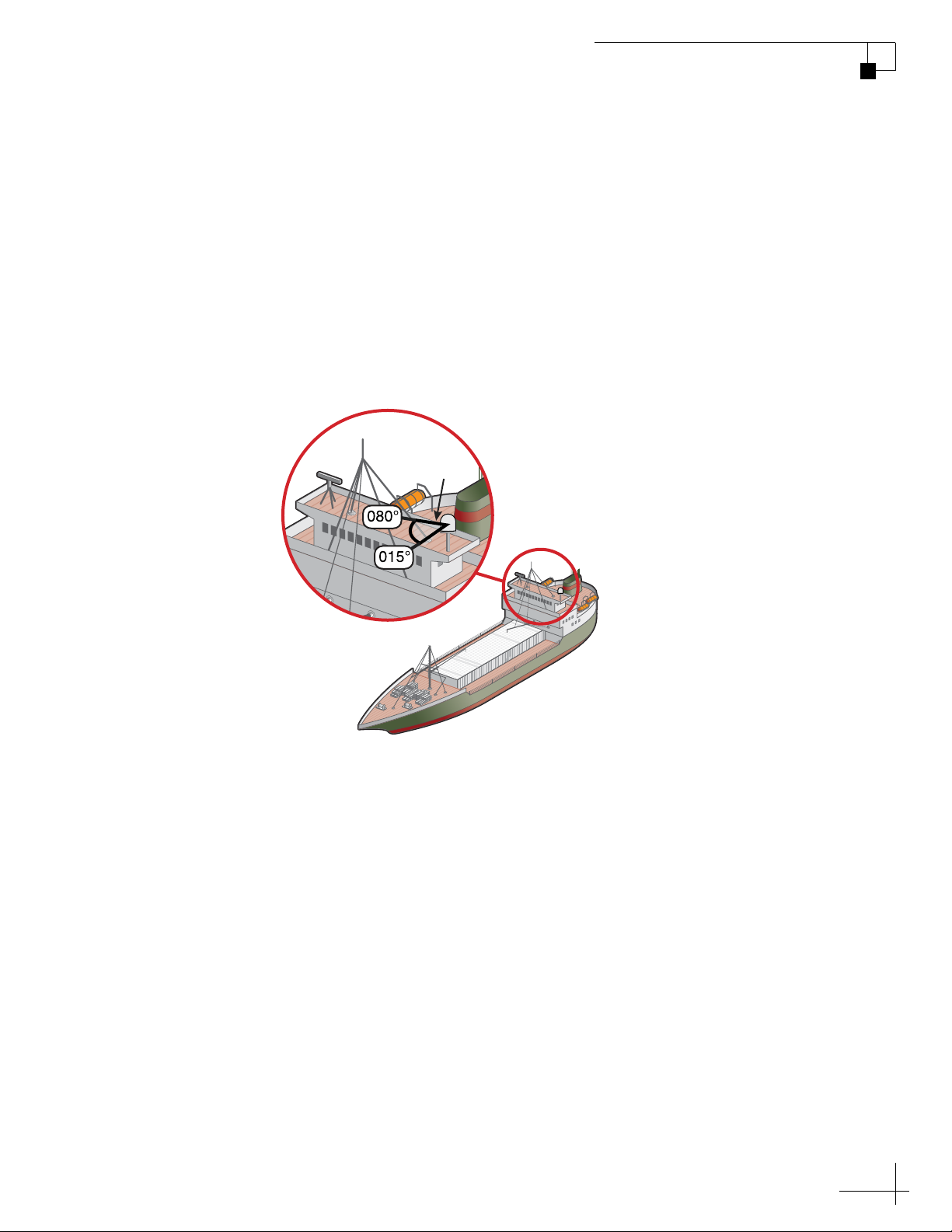
No-Transmit Zones Overview
To prevent exposure to the antenna’s radiated RF (radio frequency)
energy, you can configure up to two no-transmit zones for areas where
crew and passengers frequent. Whenever the antenna points within a
no-transmit zone, the system disables the transmitter. Transmission
capability is restored whenever the antenna points outside the zone.
NOTE: See “RF Radiation Hazard Area” on page 6 for details on the
minimum safety distances.
Figure 4-1 Example of a No-Transmit Zone
No-Transmit
Zone
TracPhone V3-IP User’s Guide
No-Transmit Zones
31
Page 34
TracPhone V3-IP User’s Guide
No-Transmit Zones
Status of No-Transmit Zones
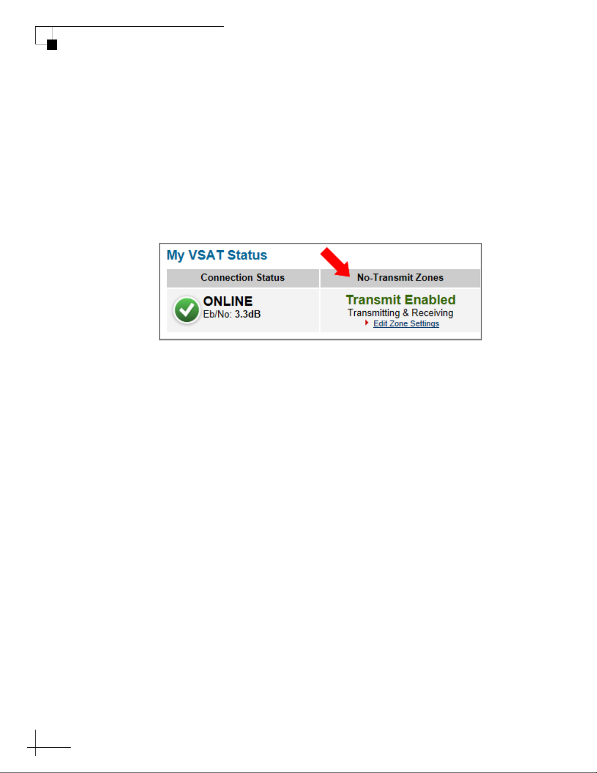
You can view the current status of the system’s no-transmit zones on
the Home page of the TracPhone V3-IP web interface. If no-transmit
zones have been set up, “My VSAT Status” includes a No-Transmit
Zones column. If this column is missing, no transmit zones have not
yet been set up or they have been cleared from memory. See
“Establishing No-Transmit Zones” on page 33 for details on setting up
no-transmit zones.
Figure 4-2 No-Transmit Zones Status Information on Home Page
The No-Transmit Zones column will display one of the following
status indications:
• Transmit Enabled (green) – One or two no-transmit zones
have been set up and are currently enforced. However, the
antenna is not pointing within a no-transmit zone.
• Transmit Disabled (orange) – One or two no-transmit
zones have been set up and are currently enforced. The
antenna is pointing within a no-transmit zone and will not
transmit.
• Transmit Enabled (red) – One or two no-transmit zones
have been set up, but they are currently being ignored. The
antenna can transmit in any direction without restriction.
NOTE: You can also view the status of no-transmit zones on the ICM’s front
panel LCD (go to No-Transmit Zones).
32
Page 35
Establishing No-Transmit Zones
To configure a no-transmit zone, follow these steps:
1. Identify the necessary azimuth range for the zone (see
“Identify the Azimuth Range”).
2. At the TracPhone V3-IP web interface, configure a no-transmit
zone for that azimuth range (see “Configure the No-Transmit
Zone(s) at the Web Interface” on page 34).
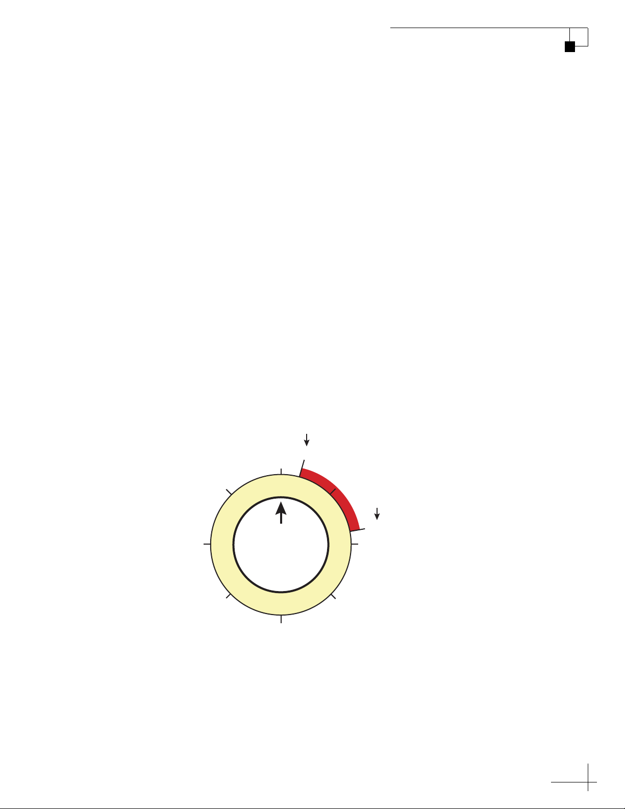
Identify the Azimuth Range
First, you need to determine the necessary azimuth range for the notransmit zone(s). You will need to enter, in clockwise order, the
beginning and ending azimuths that define the outer boundaries of the
zone, relative to the antenna’s forward arrow, which should be
pointing toward the bow.
TracPhone V3-IP User’s Guide
No-Transmit Zones
NOTE: Each no-transmit zone must span at least 5º. Therefore, be sure to set
beginning and ending azimuths at least 5º apart.
Figure 4-3 Beginning and Ending Azimuths Defining a No-Transmit Zone (Example)
Beginning Azimuth
FROM
315
000
Forward
Antenna
180
015
No-Transmit Zone
(Example)
Ending Azimuth
TO
080
090270
135225
33
Page 36
TracPhone V3-IP User’s Guide
No-Transmit Zones
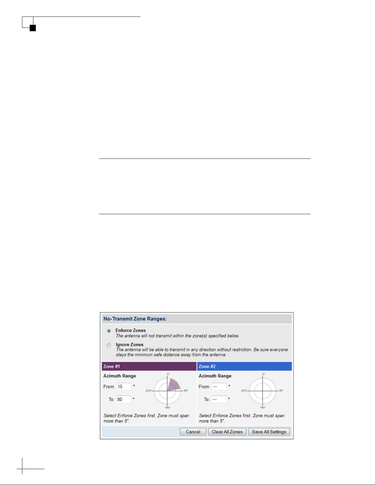
Configure the No-Transmit Zone(s) at the Web Interface
1. At the TracPhone V3-IP web interface, click the Settings tab.
2. Click Edit.
3. If the Login window appears, log in with the Administrator
4. In No-Transmit Zone Ranges, make sure Enforce Zones is
Important!
When “Enforce Zones” is selected, the antenna will not transmit
whenever it points within one of your configured no-transmit zones. If
“Ignore Zones” is selected instead, the zones are disabled, allowing the
antenna to transmit in any direction without restriction.
Then click No-Transmit Zones.
password.
selected.
5. Enter the azimuth range for Zone 1.
6. If you wish to set up a second no-transmit zone, enter the
azimuth range for Zone 2.
7. Click Save All Settings.
8. At the confirmation message, click Save.
Figure 4-4 Configuring No-Transmit Zones
34
Page 37
Disabling No-Transmit Zones
You can disable your programmed no-transmit zones to temporarily
remove all restrictions on transmissions. This function permits the
antenna to ignore the zones; it does not delete them from the system’s
memory.
CAUTION
Disabling no-transmit zones allows the antenna to transmit in any
direction, even if the antenna is pointing in an area accessible to
passengers and crew. Make sure everyone stays the minimum safe
distance away from the antenna while it is in use (see “RF Radiation
Hazard Area” on page 6).
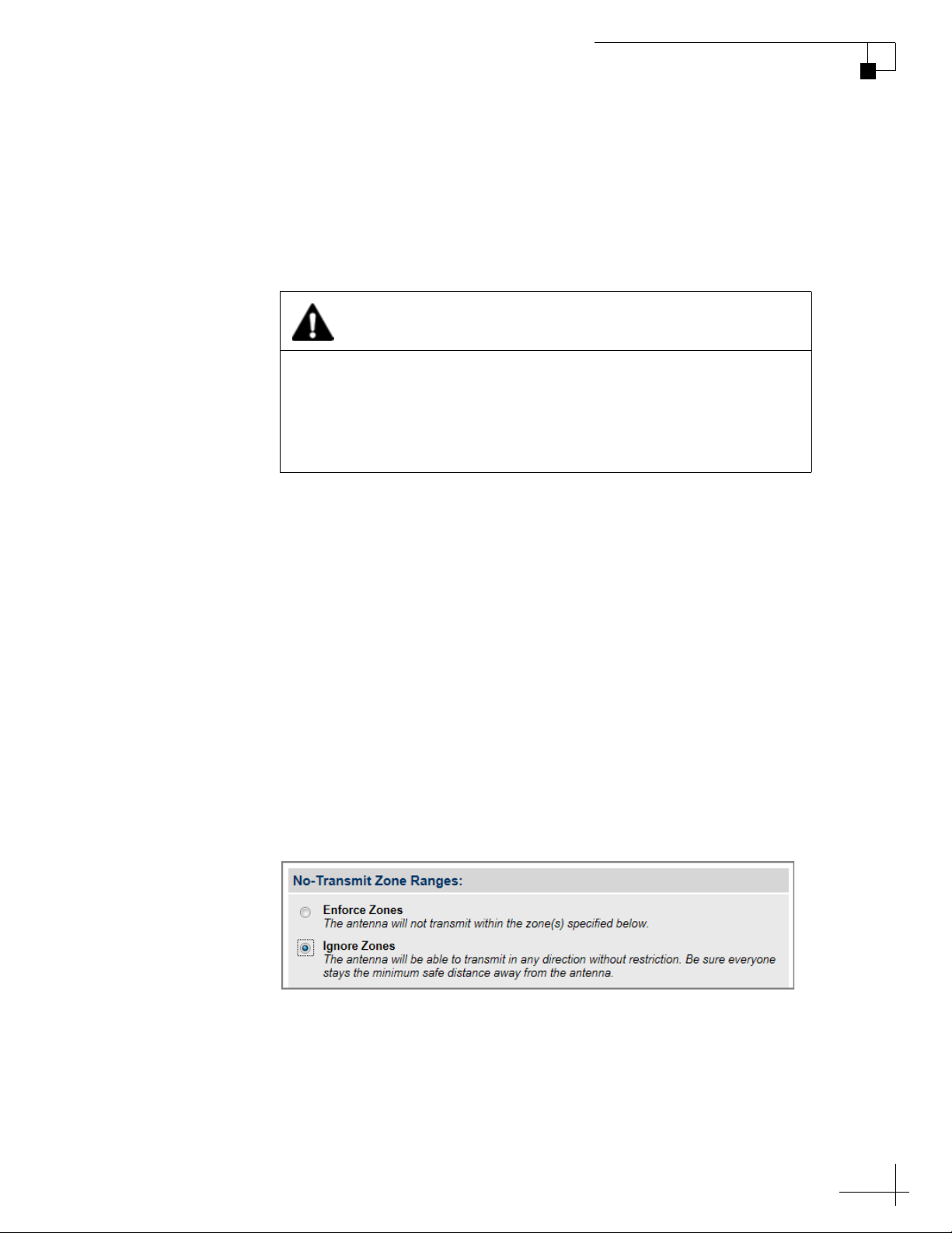
To disable the no-transmit zones, follow these steps:
TracPhone V3-IP User’s Guide
No-Transmit Zones
1. At the TracPhone V3-IP web interface, click the Settings tab.
Then click No-Transmit Zones.
2. Click Edit.
3. If the Login window appears, log in with the Administrator
password.
4. In No-Transmit Zone Ranges, click Ignore Zones.
5. Click Save All Settings.
6. At the confirmation message, click Ignore Zones.
Figure 4-5 Disabling No-Transmit Zones
35
Page 38
TracPhone V3-IP User’s Guide
No-Transmit Zones
Clearing No-Transmit Zones
You can clear all no-transmit zones from the system’s memory. Unlike
disabling zones, clearing zones permanently deletes them.
CAUTION
Clearing no-transmit zones allows the antenna to transmit in any
direction without restriction. Make sure everyone stays the
minimum safe distance away from the antenna while it is in use
(see “RF Radiation Hazard Area” on page 6).
NOTE: This procedure explains how to clear no-transmit zones using the
TracPhone V3-IP web interface. If you prefer, you may use the front panel
LCD menu instead (go to Diagnostic Tools > Factory Reset).
To clear the no-transmit zones, follow these steps:
1. At the TracPhone V3-IP web interface, click the Settings tab.
Then click No-Transmit Zones.
2. Click Edit.
3. If the Login window appears, log in with the Administrator
password.
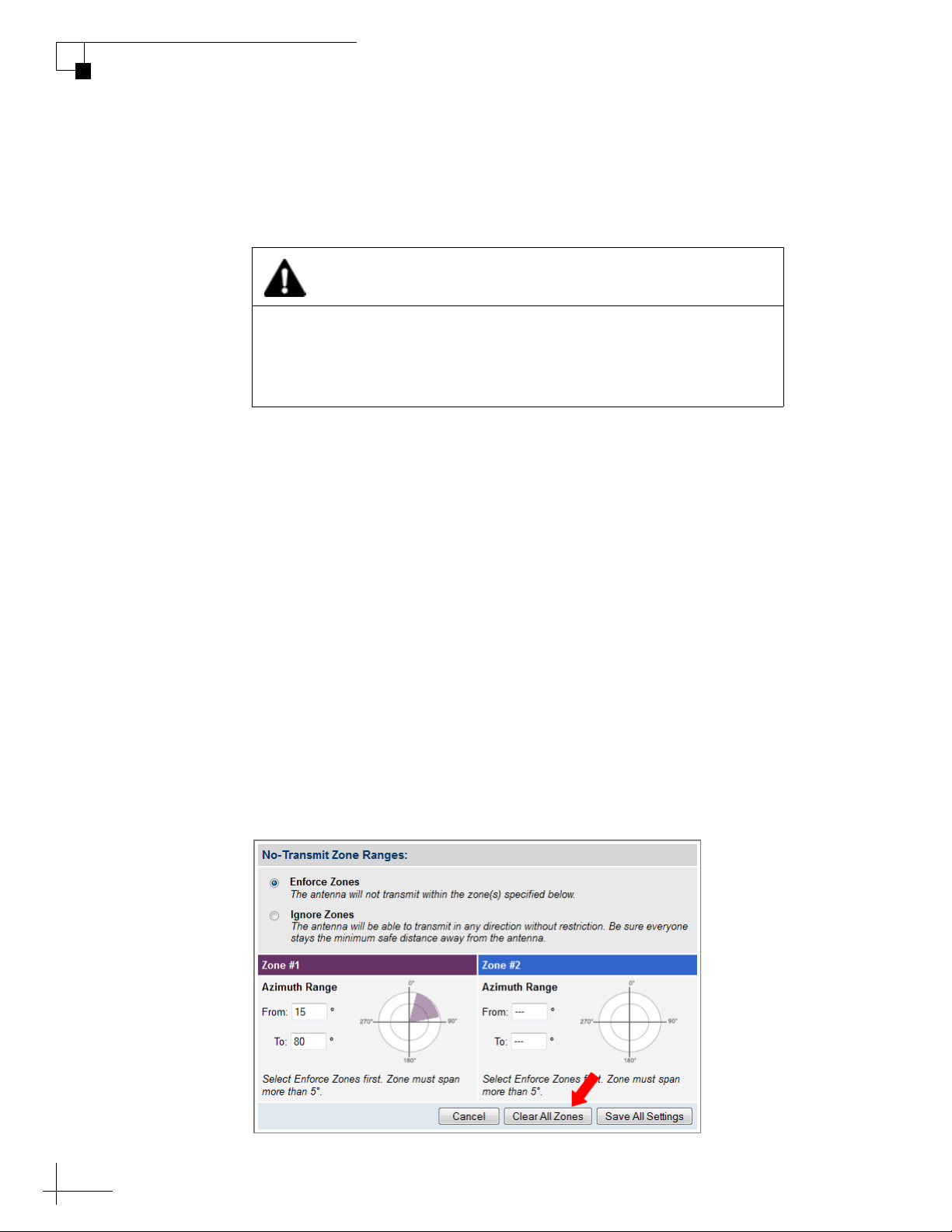
4. In No-Transmit Zone Ranges, click Clear All Zones.
5. At the confirmation message, click Clear Zones.
Figure 4-6 Clearing No-Transmit Zones
36
Page 39

TracPhone V3-IP User’s Guide
Voice Connections
5. Voice Connections
This section covers everything you need to know about the enhanced
voice service. It explains how to place calls, add virtual numbers, check
VoiceMail, send a fax, and access your voice account online.
Contents
Voice Service Overview ................................................... 39
Making a Ship-to-Shore Call ........................................... 40
Making a Shore-to-Ship Call ........................................... 42
Virtual Numbers............................................................... 43
VoiceMail ......................................................................... 44
Faxing.............................................................................. 46
Accessing Your Voice Account ........................................ 48
37
Page 40
Voice Service Overview
KVH’s enhanced voice service – Voice over IP (VoIP) optimized for
satellite communications – allows you to make and receive phone calls
via the TracPhone system and the mini-VSAT Broadband service.
Voice traffic is given priority on the network over standard Internet
data to ensure the highest quality voice connections at all times.
Important!
The TracPhone V3-IP voice service will not provide Automatic
Number Identification or Automatic Location Information capabilities
associated with emergency services, such as 911 or E911. In addition,
the voice service will not work in the event of either a network service
outage or a power failure. Therefore, it is critical that you maintain
your vessel’s separate distress and safety communications system for
emergency calls. Be sure to inform anyone who may use the TracPhone
V3-IP of the limitations of emergency services. The manufacturer,
distributor, and service provider shall not be liable for, and expressly disclaim,
any direct or indirect damages, claims, losses, expenses, liabilities, actions,
risks, or harms arising out of or related to the services provided through this
equipment, including without limitation, emergency services.
TracPhone V3-IP User’s Guide
Voice Connections
How the Voice Service Works
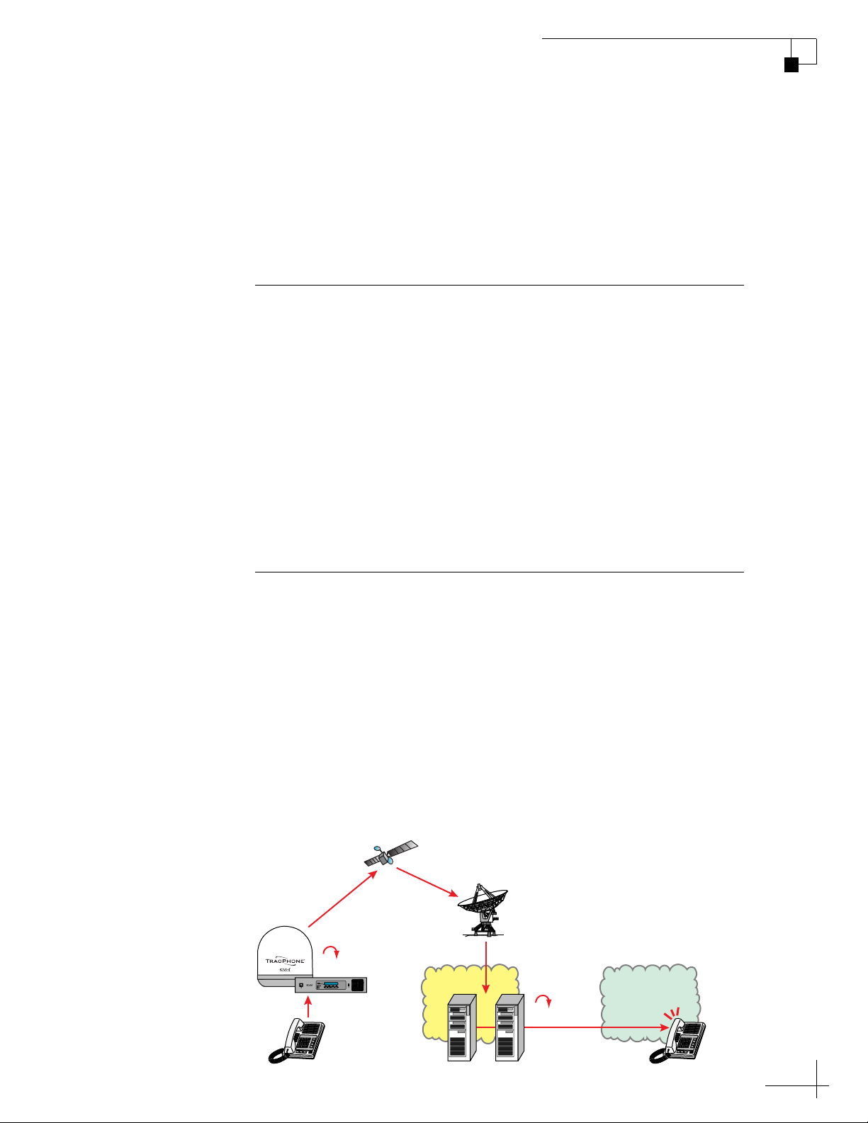
When you dial a phone number using the ship’s analog phone, the
TracPhone system converts its analog signal into digital VoIP data and
transmits it over the mini-VSAT Broadband network to an Internetbased SIP (session initiation protocol) server. The digital VoIP data is
then converted back into its original analog signal and routed via a
proxy server to the appropriate public switched telephone network
(PSTN). Finally, the telephone network’s carrier completes the call to
ring the desired shore phone line.
Figure 5-1 Voice Service Call Routing
Tr acPhone
System
Converted
to Digital
D
A
mini-VSAT Broadband
Service
Hub
Converted
Internet
to Analog
DA
Telephone
Network
(PSTN)
Ship Phone
SIP Server Proxy
Shore Phone
39
Page 41

TracPhone V3-IP User’s Guide
Voice Connections
Making a Ship-to-Shore Call
To place a call from the vessel, follow these steps:
1. Make sure the TracPhone system is online.
2. Pick up the handset on any phone connected to the ICM. You
should hear a dial tone. If you don’t, check the phone line
status on the web interface’s Home tab.
3. Dial the phone number you wish to call. The dialing sequence
you use depends on the vessel’s Line 1 phone number.
Dialing a Number Outside the Country Assigned to Line 1
Dial the number as an international call:
<International prefix, as originating from your Line 1 country>
+ <country code>
+ <area/city code>
+ <local phone number>
Dialing a Number Within the Country Assigned to Line 1
Dial the number as an in-country call:
<area/city code>
+ <local phone number>
Dialing a Number Within the Country & Area Code Assigned to Line 1
Dial the number as a local call:
<local phone number>
NOTE: When you place a call, your voice travels to a satellite in space then
back to Earth. This transit will cause a brief delay (approximately 1/2 second)
in your conversation.
40
Page 42
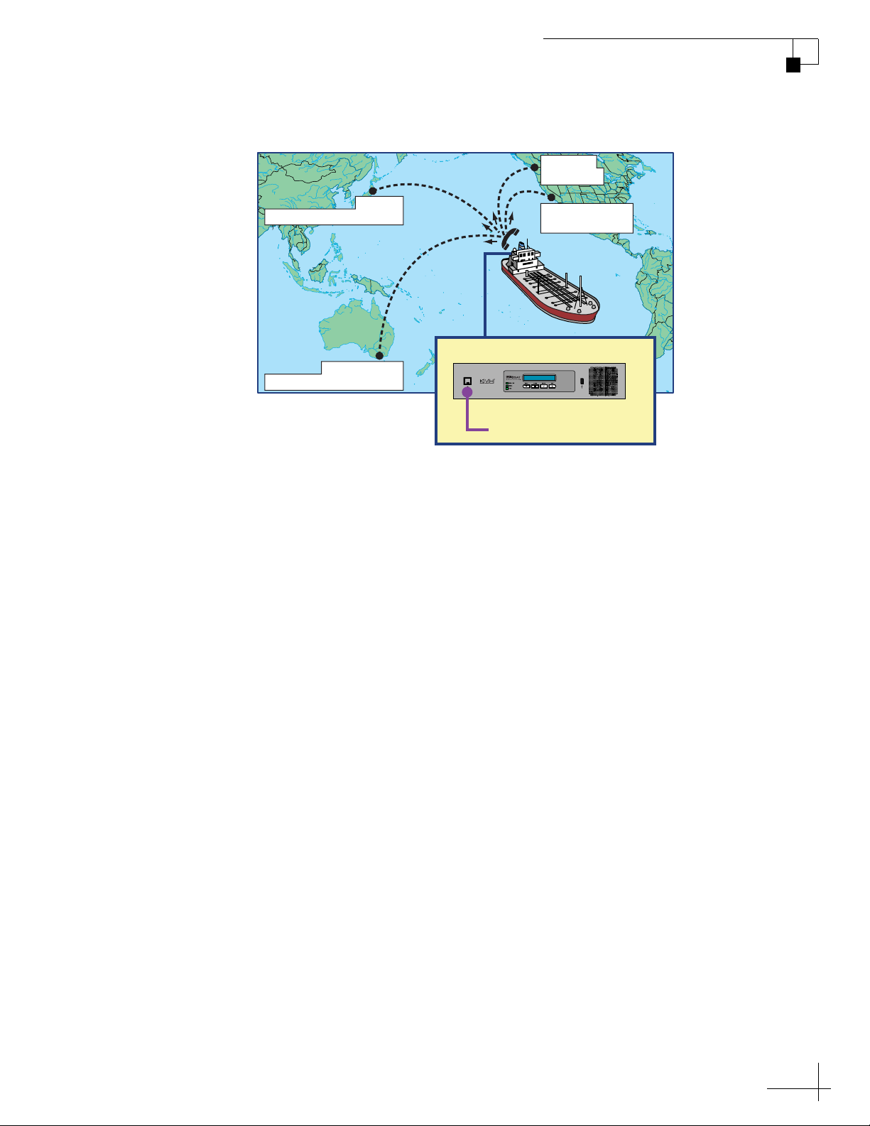
Figure 5-2 Ship-to-Shore Calls (Example)
TracPhone V3-IP User’s Guide
Voice Connections
Seattle
4620951
011-81-3-90126382
Tokyo
Melbourne
011-61-3-82125092
011 = International prefix
(from Line 1 country)
61 = Country code
3 = Area/City code
82125092 = Local phone no.
ICM
Phone Line 1
1-206-3538023 (Seattle)
Los Angeles
310-6910951
On a fixed rate plan, all calls are charged termination fees as calls
originating from the U.S., regardless of vessel location or phone
number. Long distance rates will apply. For details, refer to the rate
sheet available online at www.kvh.com/mvbcustomercenter.
41
Page 43
TracPhone V3-IP User’s Guide
Voice Connections
Making a Shore-to-Ship Call
People on shore call your vessel by dialing your vessel’s phone
number. They are billed international and long-distance charges based
on the vessel’s phone number, and not on the location of the vessel.
Therefore, when you set up your phone number during service
activation, it is advisable to select the same country code and area/city
code you use at home. This will allow family, friends, and business
associates in your home region to call your vessel as an in-country call.
NOTE: If you wish to change your vessel’s phone number, contact KVH’s
Satellite Airtime & Product Activation department. See “Contacting the
Satellite Airtime and Product Activation Department” on page 15.
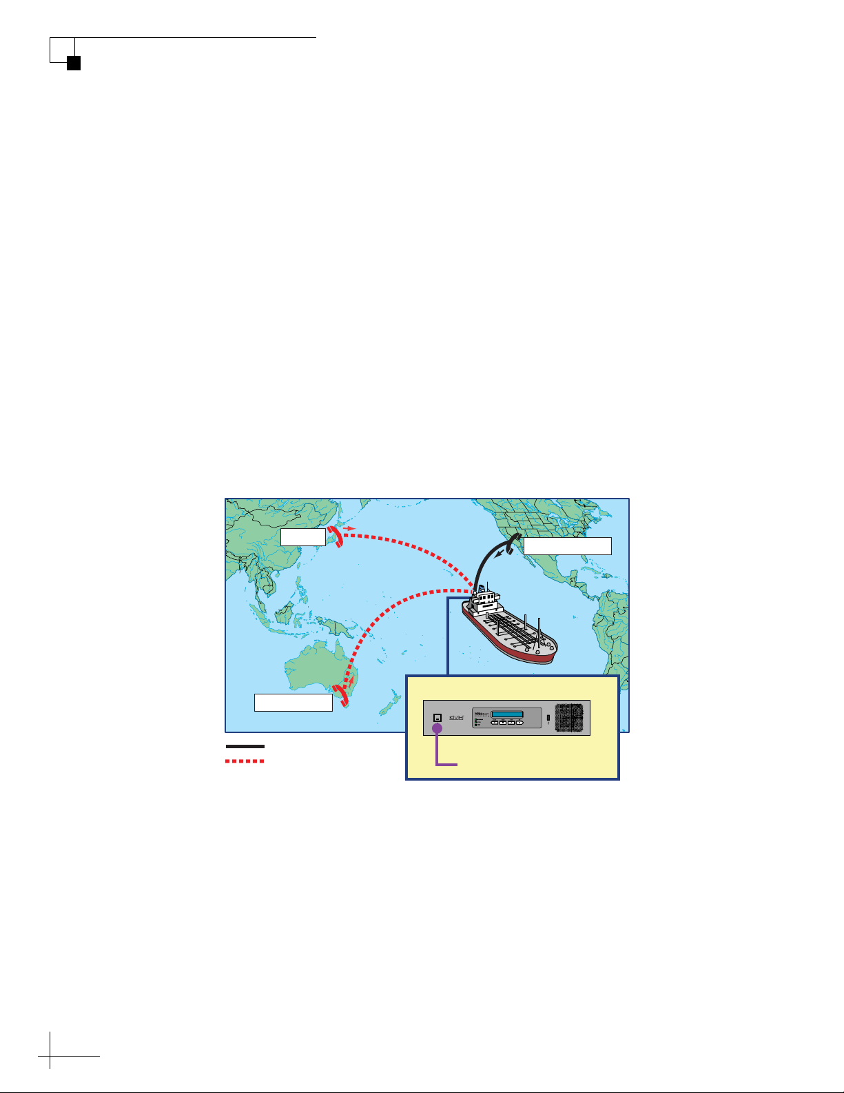
In the example shown here, people in Los Angeles who call the
vessel’s U.S.-based phone number will not be charged international
fees.
Figure 5-3 Shore-to-Ship Calls (Example)
Tokyo
ICM
Melbourne
= In-country call
= International call
Los Angeles
Phone Line 1
1-206-3538023 (U.S.)
42
Page 44
Virtual Numbers
Melbourne
Tokyo
Los Angeles
= In-country call
= International call
1-206-3538023 (U.S.)
Phone Line 1
61-2-84916302 (Australia)
81-3-90126382 (Japan)
Virtual Numbers
ICM
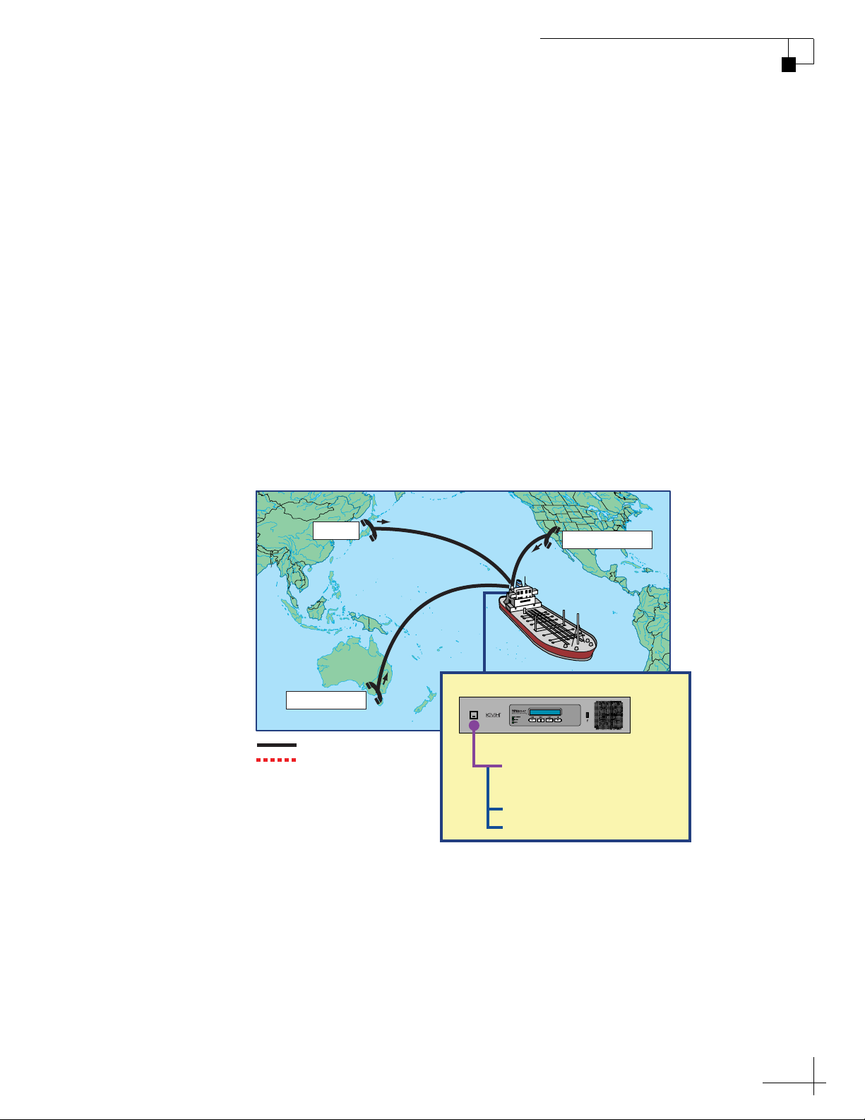
For an additional fee, you may assign up to five virtual phone
numbers to the vessel phone line. Each of these numbers can be set up
with a different country code and area/city code, allowing people on
shore within those regions to avoid international or long-distance
charges when they call the vessel.
To set up virtual numbers, contact KVH’s Satellite Airtime & Product
Activation department. See “Contacting the Satellite Airtime and
Product Activation Department” on page 15.
In the example shown here, the vessel’s company has offices in Tokyo
and Melbourne. Therefore, they set up Japanese and Australian virtual
numbers so that their employees on shore can call the vessel without
running up an international phone bill.
TracPhone V3-IP User’s Guide
Voice Connections
Figure 5-4 Virtual Numbers (Example)
43
Page 45

TracPhone V3-IP User’s Guide
Voice Connections
VoiceMail
KVH’s enhanced voice service offers a similar suite of features as you
might find with any landline telephone service. One of these features
is VoiceMail.
With VoiceMail, people who call the vessel may record a message if
you are unable to answer the call or the line is busy. You can then play
back and listen to your messages anytime (24/7) from anywhere, even
if you are not currently onboard the vessel.
Recording a VoiceMail Personal Greeting
To record your VoiceMail personal greeting, follow these steps:
1. Pick up the handset on any phone connected to the ICM. You
should hear a dial tone.
2. Dial 123# to connect to the VoiceMail system.
3. Press 2 to access your mailbox.
4. Press 1 to access your personal greeting.
5. Press 2 to change your greeting. You will be prompted to
record your greeting.
6. Press 1 to listen to your personal greeting.
7. When you are satisfied with your greeting, press 3 to accept
and activate your greeting. You will hear the message “Your
personal greeting has been activated.”
Listening to Your VoiceMail Messages
If you hear a fast dial tone pulse in the phone’s handset, you have new
VoiceMail messages. To listen to your VoiceMail messages, follow
these steps:
1. Dial 123# to connect to the VoiceMail system.
44
2. Press 1 to listen to your messages.
3. Follow the spoken instructions to listen to, save, and/or delete
your messages.
Page 46

TracPhone V3-IP User’s Guide
Voice Connections
Listening to Your Messages on Shore
You still have access to your VoiceMail messages when you disembark
the vessel. Choose one of the following options:
• Use a computer: Go to your voice account web page (see
“Accessing Your Voice Account” on page 48). Then click the
VoiceMail button.
• Use a regular landline telephone: Dial the number for your vessel
phone line (Line 1), press *, then enter your PIN (provided during
service activation).
45
Page 47

TracPhone V3-IP User’s Guide
Voice Connections
Faxing
You can fax documents via the enhanced voice service. Connect a fax
machine to the “Voice Line 1” jack on the ICM and dial the fax number
as you would a voice call (see “Making a Ship-to-Shore Call” on
page 40).
NOTE: Faxing requires 70 kbps bandwidth for sending and up to 90 kbps
bandwidth for receiving.
For extremely reliable faxing, KVH offers the UCH-250 fax server (see
“UCH-250 Fax Server” on page 47). The UCH-250 avoids the industry-
wide problem of dropped or incomplete faxes commonly associated
with faxing over Voice over IP (VoIP) connections.
46
Page 48
UCH-250 Fax Server
UCH-250
Fax Server
ICM
Fax Machine
Bridge Phone
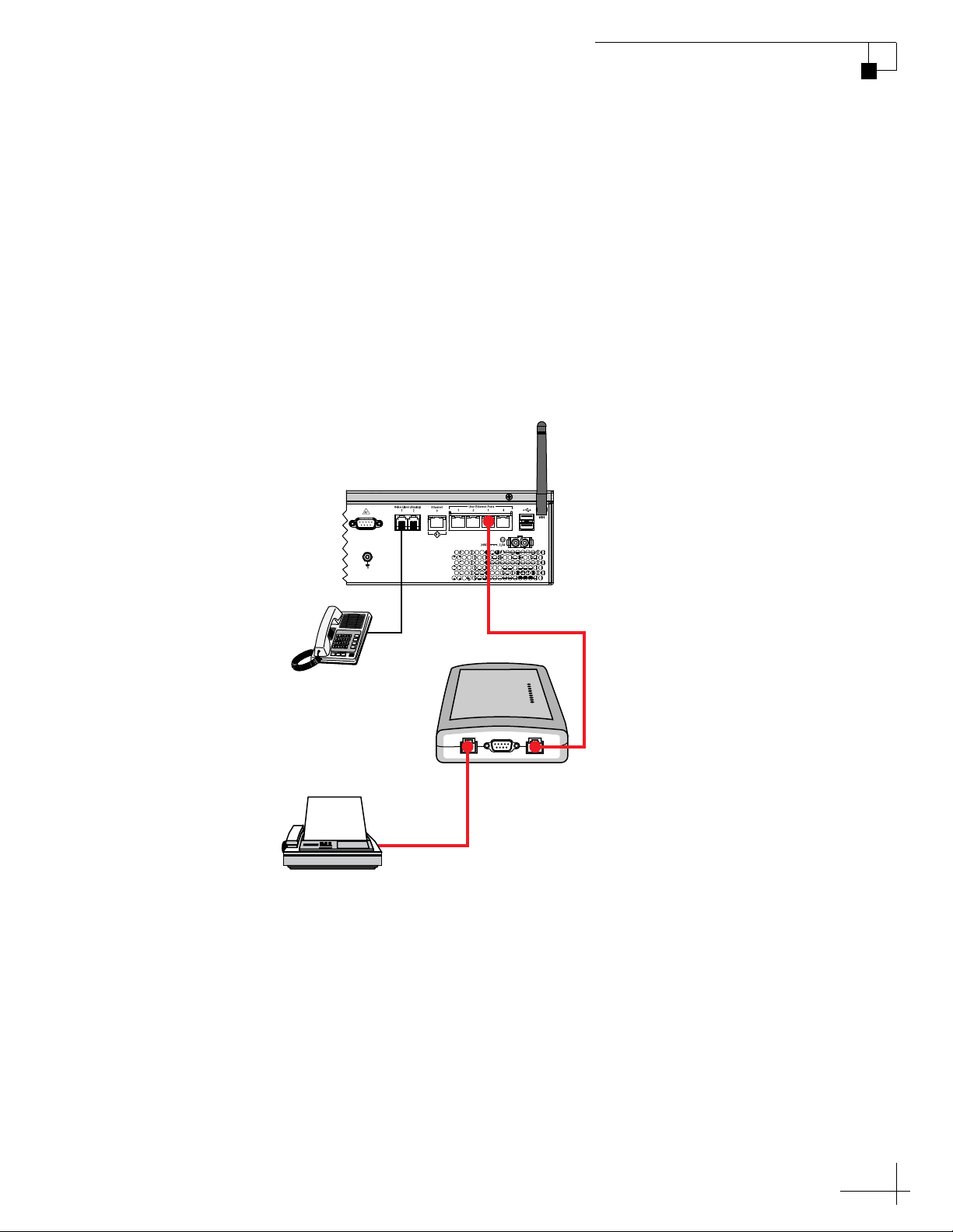
Faxing over Internet Protocol can be unreliable at times (normally an
80% success rate). Glitches like latency, packet loss, and jitter, common
with any VoIP connection, can interrupt the synchronization necessary
for fax communications. KVH’s optional UCH-250 Fax Server (KVH
part no. 19-0520) overcomes these limitations by providing a dedicated
fax line with the reliability of a fully managed, store-and-forward
system. In addition to installing the fax server, you will need to
activate the supplemental fax service. Contact your dealer/distributor
for details.
Figure 5-5 UCH-250 Fax Server Connections
TracPhone V3-IP User’s Guide
Voice Connections
47
Page 49
TracPhone V3-IP User’s Guide
Voice Connections
Accessing Your Voice Account
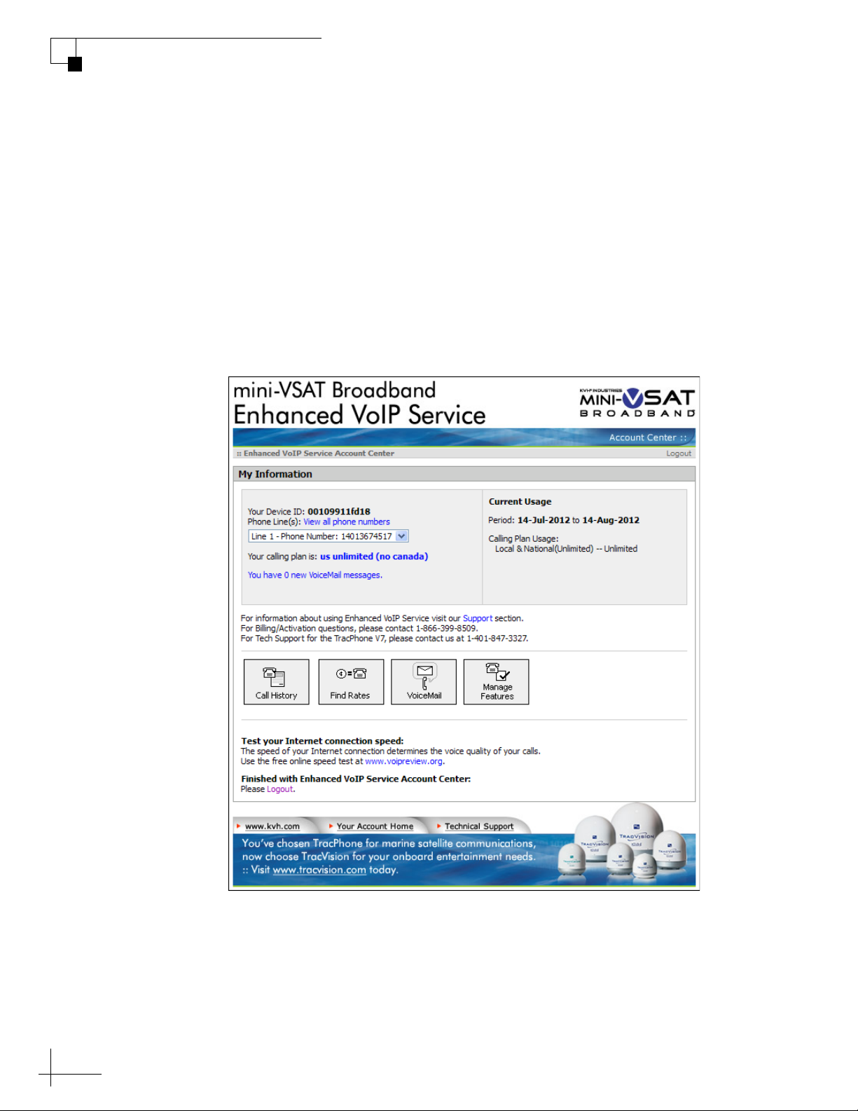
You can manage your account online at KVH’s Enhanced VoIP Service
Account Center. You can view and configure all of the various calling
features available to you, as well as view account information and
listen to VoiceMails. To log onto the site, follow these steps:
1. Go to http://kvh.myaccountcenter.net.
2. At the login page, enter your Line 1 phone number and PIN,
provided during service activation. Then click Login.
Figure 5-6 Enhanced VoIP Service Account Center
48
Page 50

6. Network Configuration
This section explains the three main options for connecting your vessel’s
computers to the TracPhone system: wired DHCP, wireless DHCP, and
static IP. (You can use one, two, or all three configurations to meet your
network requirements.) It also provides an overview of the advanced
network settings that are available on the ICM.
Contents
Wired DHCP Configuration............................................... 51
TracPhone V3-IP User’s Guide
Network Configuration
Wireless DHCP Configuration .......................................... 52
Configuring Computers for DHCP .................................... 55
Static IP Configuration..................................................... 60
LAN Settings on ICM........................................................ 63
Cache Settings on ICM .................................................... 65
Physical Ethernet Port Configurations ............................. 66
CommBox Settings on ICM .............................................. 70
Reset to Factory Configuration ........................................ 71
49
Page 51
Wired DHCP Configuration
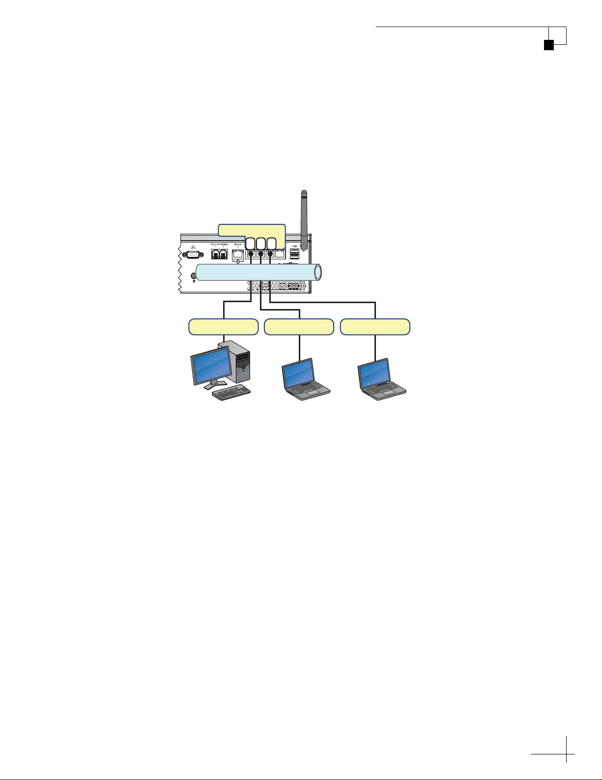
In a wired DHCP configuration, vessel computers connect to the ICM
via Ethernet cables and receive IP addresses from the ICM. This is the
system’s default configuration.
Figure 6-1 Wired DHCP Configuration (Example)
TracPhone V3-IP User’s Guide
Network Configuration
ICM
User Ethernet
1 2 3
LAN: 192.168.5.1
192.168.5.100 192.168.5.101 192.168.5.102
Bridge PC
Crew PCOfficers PC
To configure a wired DHCP network connection, follow these steps:
1. Connect your computers and other network devices to any of
the four “User Ethernet” ports on the rear panel of the ICM.
NOTE: Use straight-through 100 Mbps fast Ethernet UTP CAT5 cables (or
better) with RJ45 connectors.
2. Make sure the computers are configured for DHCP addressing
(see “Configuring Computers for DHCP” on page 55).
51
Page 52
TracPhone V3-IP User’s Guide
User Ethernet
ICM
Bridge PC
1 2
Crew PCs
Officers PC
192.168.5.100 192.168.5.101
192.168.5.102
192.168.5.103
LAN: 192.168.5.1
Network Configuration
Wireless DHCP Configuration
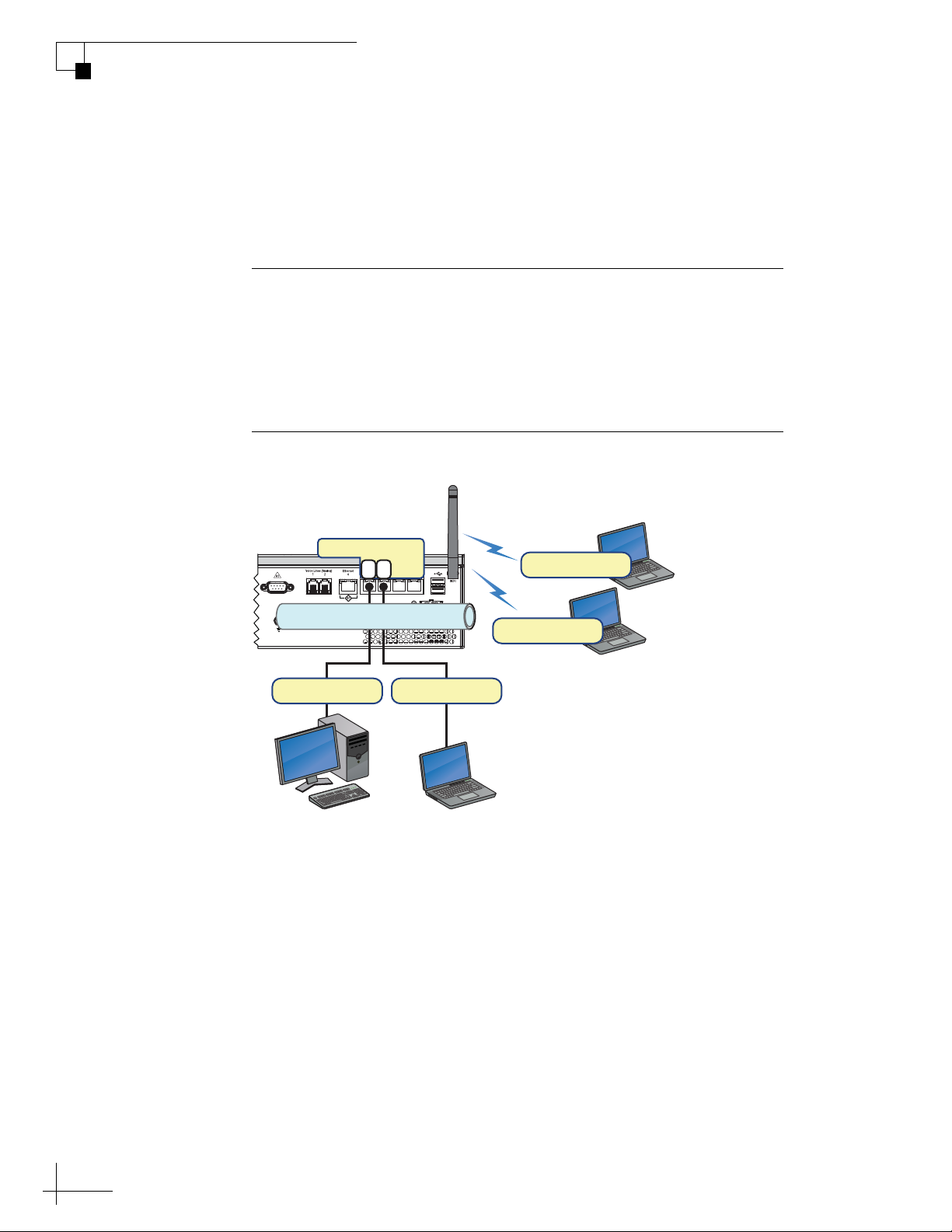
In a wireless (Wi-Fi) DHCP configuration, vessel computers connect to
the ICM via its built-in wireless access point (WAP) and receive IP
addresses from the ICM.
Important!
The range of the ICM’s WAP will depend on the layout and structure
of the vessel. For example, wireless signals degrade when passing
through bulkheads and near metal masses. If the system is installed
on a steel vessel, you might need a special WAP and the services of a
technician with advanced networking expertise.
Figure 6-2 Wireless DHCP Configuration (Example)
52
To configure a wireless DHCP network connection, follow these steps:
1. Make sure the computers are equipped with a wireless
network interface card and configured for DHCP addressing
(see “Configuring Computers for DHCP” on page 55).
2. Enable the wireless access point on the ICM and apply security
settings to protect it from outside intrusion (see “Wireless
Settings on ICM” on page 53).
Page 53

Wireless Settings on ICM
NOTE: If the optional CommBox software is enabled, or the ICM is
configured for Dual Dome-Secondary or Legacy mode, the Network Settings
page of the ICM will not contain any configurable fields. (See “CommBox
Features” on page 81 for details on enabling the CommBox software. See
“Physical Ethernet Port Configurations” on page 66 for details on changing
the ICM’s configuration.)
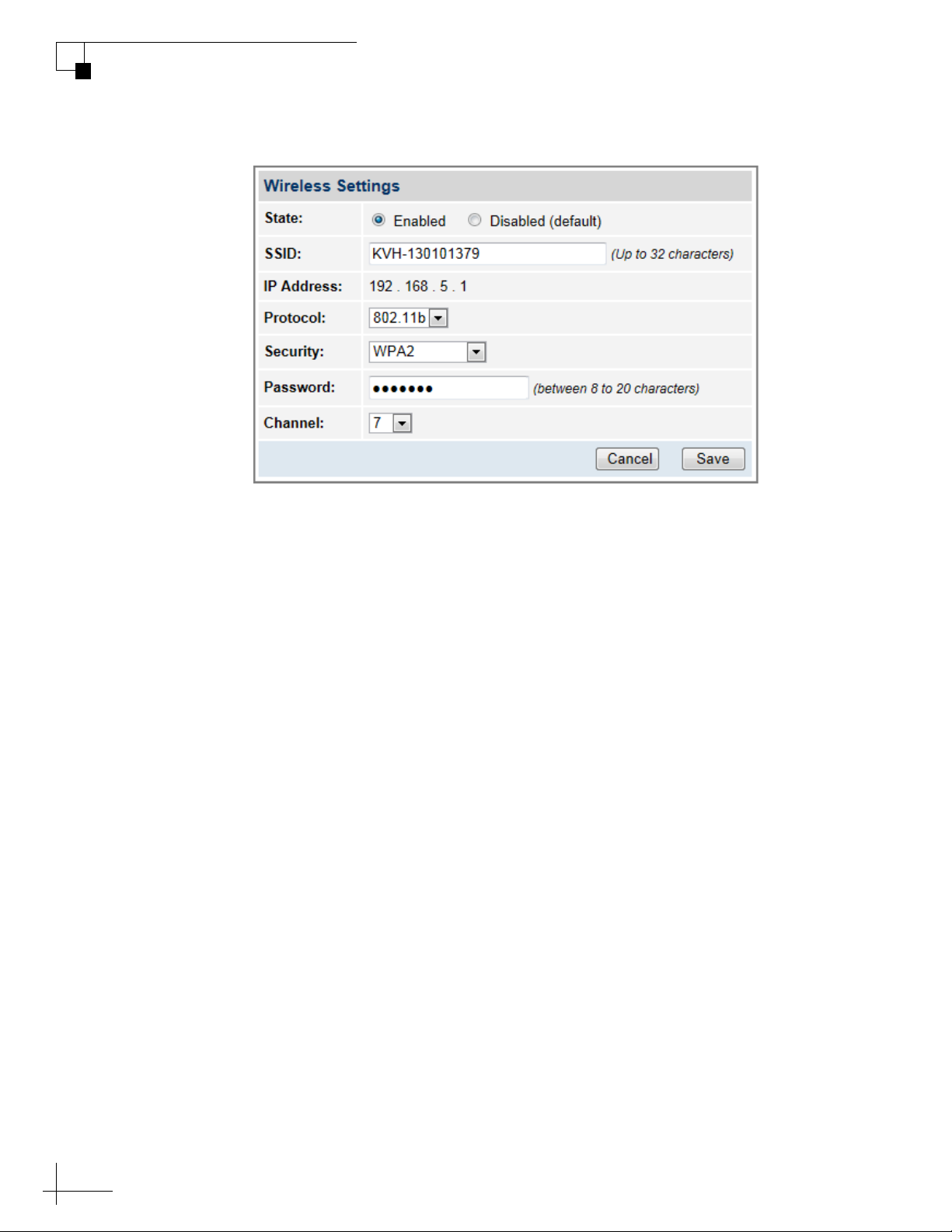
To enable a wireless network connection and protect it from outside
intrusion, follow these steps:
1. At the TracPhone V3-IP web interface, click the Settings tab.
Then click Network Settings.
2. In Wireless Settings, click Edit.
3. If the Login window appears, log in with the Administrator
password.
TracPhone V3-IP User’s Guide
Network Configuration
4. Select Enabled.
5. Set the following wireless options:
SSID: Keep the default name, or enter a unique name for the
wireless network.
Protocol: Select either protocol – 802.11b or 802.11g.
Security: Select either security type – WPA2 or WEP (128-bit).
Password/Passphrase: If you selected WPA2, enter a password
(between 8-20 characters). If you selected WEP, enter a
passphrase (must be 13 characters).
Channel: Keep the default channel, or select any other channel
for wireless communications.
6. Click Save.
7. At the confirmation message, click Save.
53
Page 54
TracPhone V3-IP User’s Guide
Network Configuration
Figure 6-3 Wireless Settings
54
Page 55

Configuring Computers for DHCP
To configure your computers for DHCP, allowing them to receive IP
addresses from the ICM, follow the steps for your operating system:
• “Windows 8 DHCP Settings”
• “Windows 7 or Windows Vista DHCP Settings” on page 56
• “Windows XP DHCP Settings” on page 57
• “Mac OS X DHCP Settings” on page 59
NOTE: KVH Technical Support fully supports the five operating systems
described here: Windows 8, Windows 7, Windows Vista™, Windows XP,
and Macintosh
®
OS X.
TracPhone V3-IP User’s Guide
Network Configuration
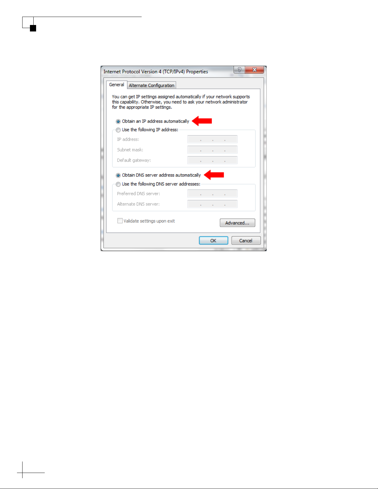
Windows 8 DHCP Settings
To configure a Windows 8 computer for DHCP addressing, follow
these steps:
1. In Control Panel, double-click Network and Sharing Center.
To open the Control Panel, go to the desktop, select Settings from the
Charms bar, then select Control Panel.
2. In Network and Sharing Center, double-click the Ethernet link
for the Ethernet connection you are using for mini-VSAT
Broadband.
3. In the Ethernet Status dialog box, click Properties. If this screen
doesn’t appear, just skip to Step 4.
4. In the Ethernet Properties dialog box, on the Networking tab,
select Internet Protocol Version 4, and then click Properties.
5. In the Internet Protocol Properties dialog box, select Obtain an
IP address automatically and Obtain DNS server address
automatically. Then click OK.
55
Page 56
TracPhone V3-IP User’s Guide
Network Configuration
Figure 6-4 Windows 8 - Internet Protocol Properties
6. In the Ethernet Properties dialog box, click Close.
Windows 7 or Windows Vista DHCP Settings
To configure a Windows 7 or Windows Vista computer for DHCP
addressing, follow these steps:
1. In Control Panel, double-click Network and Sharing Center.
(You might need to click Network and Internet first.) You can
find the Control Panel either through the Start menu or “My
Computer.”
2. In Network and Sharing Center, double-click the Local Area
Connection (Windows 7) or View Status (Windows Vista) for
the Ethernet connection you are using for mini-VSAT
Broadband.
3. In the Local Area Connection Status dialog box, click
Properties. If this screen doesn’t appear, just skip to Step 4.
56
Page 57
TracPhone V3-IP User’s Guide
Network Configuration
4. In the Local Area Connection Properties dialog box, click the
Networking tab, select Internet Protocol Version 4, and then
click Properties.
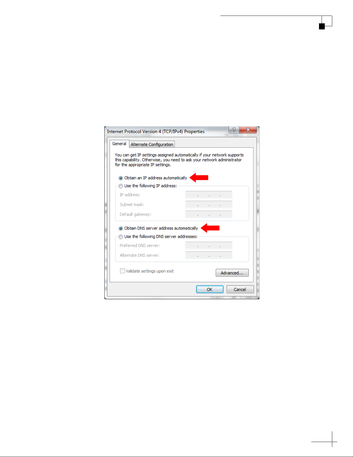
5. In the Internet Protocol Properties dialog box, select Obtain an
IP address automatically and Obtain DNS server address
automatically. Then click OK.
Figure 6-5 Windows 7/Windows Vista - Internet Protocol Properties
6. In the Local Area Connection Properties dialog box, click OK.
Windows XP DHCP Settings
To configure a Windows XP computer for DHCP addressing, follow
these steps:
1. In Control Panel, double-click Network Connections. You can
find the Control Panel either through the Start menu or “My
Computer.”
57
Page 58
TracPhone V3-IP User’s Guide
Network Configuration
2. In Network Connections, double-click the Local Area
3. In the Local Area Connection Status dialog box, click the
4. In the Local Area Connection Properties dialog box, click the
5. In the Internet Protocol (TCP/IP) Properties dialog box, click
Connection for the Ethernet connection you are using for mini-
VSAT Broadband.
General tab. Then click Properties. If this screen doesn’t appear,
simply skip to Step 4.
General tab, select Internet Protocol (TCP/IP), and then click
Properties.
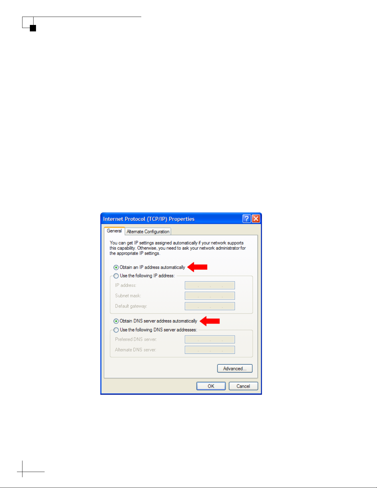
the General tab. Then select Obtain an IP address
automatically and Obtain DNS server address automatically.
Then click OK.
Figure 6-6 Windows XP - Internet Protocol (TCP/IP) Properties
58
6. In the Local Area Connection Properties dialog box, click OK.
7. Restart your computer.
Page 59
Mac OS X DHCP Settings
To configure a Mac OS X computer for DHCP addressing, follow these
steps:
1. In System Preferences, click Network.
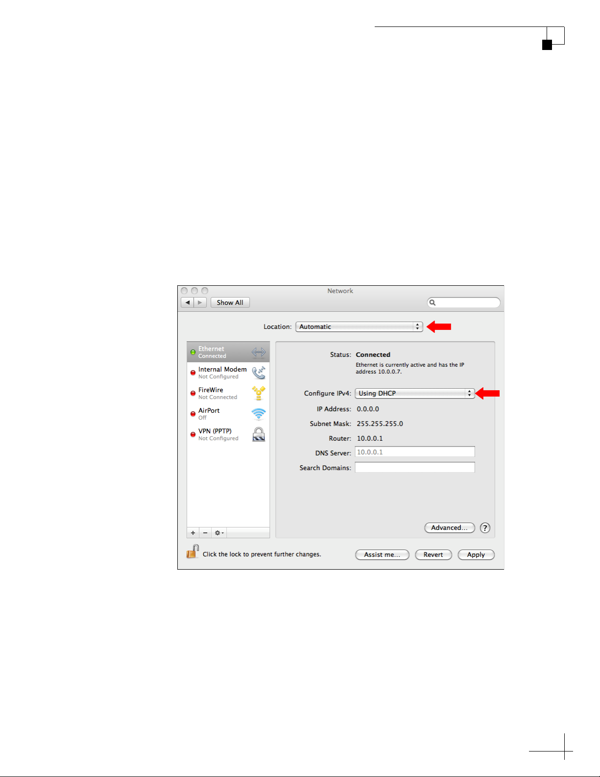
2. In the Network dialog box, select Ethernet then set the
following:
•Location: Automatic
• Configure IPv4: Using DHCP
Figure 6-7 Mac OS X - Network
TracPhone V3-IP User’s Guide
Network Configuration
3. Click Apply.
4. Restart the computer.
59
Page 60
TracPhone V3-IP User’s Guide
User Ethernet
ICM
Bridge PC
1 2
4
DHCP
Engine Room PC
Officers PC
192.168.5.100 192.168.5.101 192.168.72.100
LAN: 192.168.5.1 WAN : 192.168.72.99
Static
Firewall
Network Configuration
Static IP Configuration
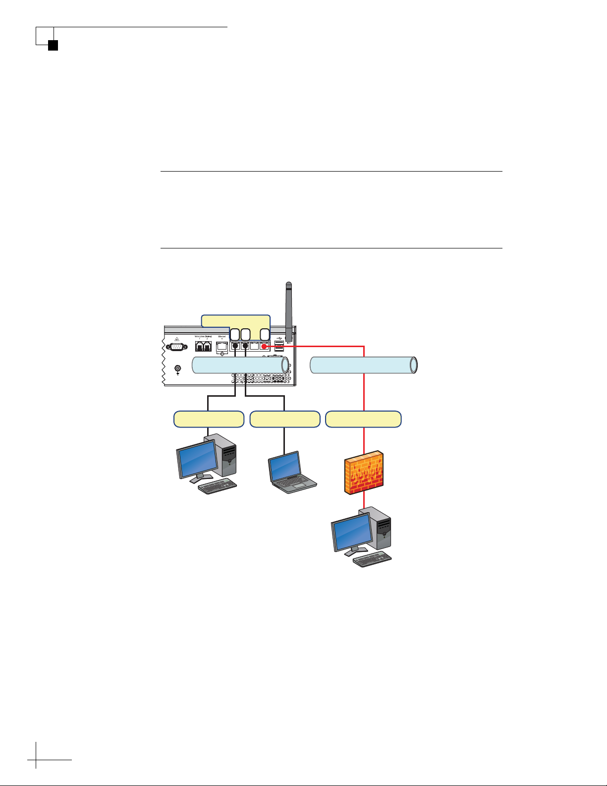
In a static IP configuration, an onboard network device is assigned a
public IP address that can be accessed directly from the Internet. It
does not receive an IP address from the ICM.
Important!
A static IP address provides an open, unprotected connection to the
Internet. Therefore, you should only assign a static IP address to a
secure device, such as a firewall router.
Figure 6-8 Static Configuration (Example)
60
Page 61
TracPhone V3-IP User’s Guide
Network Configuration
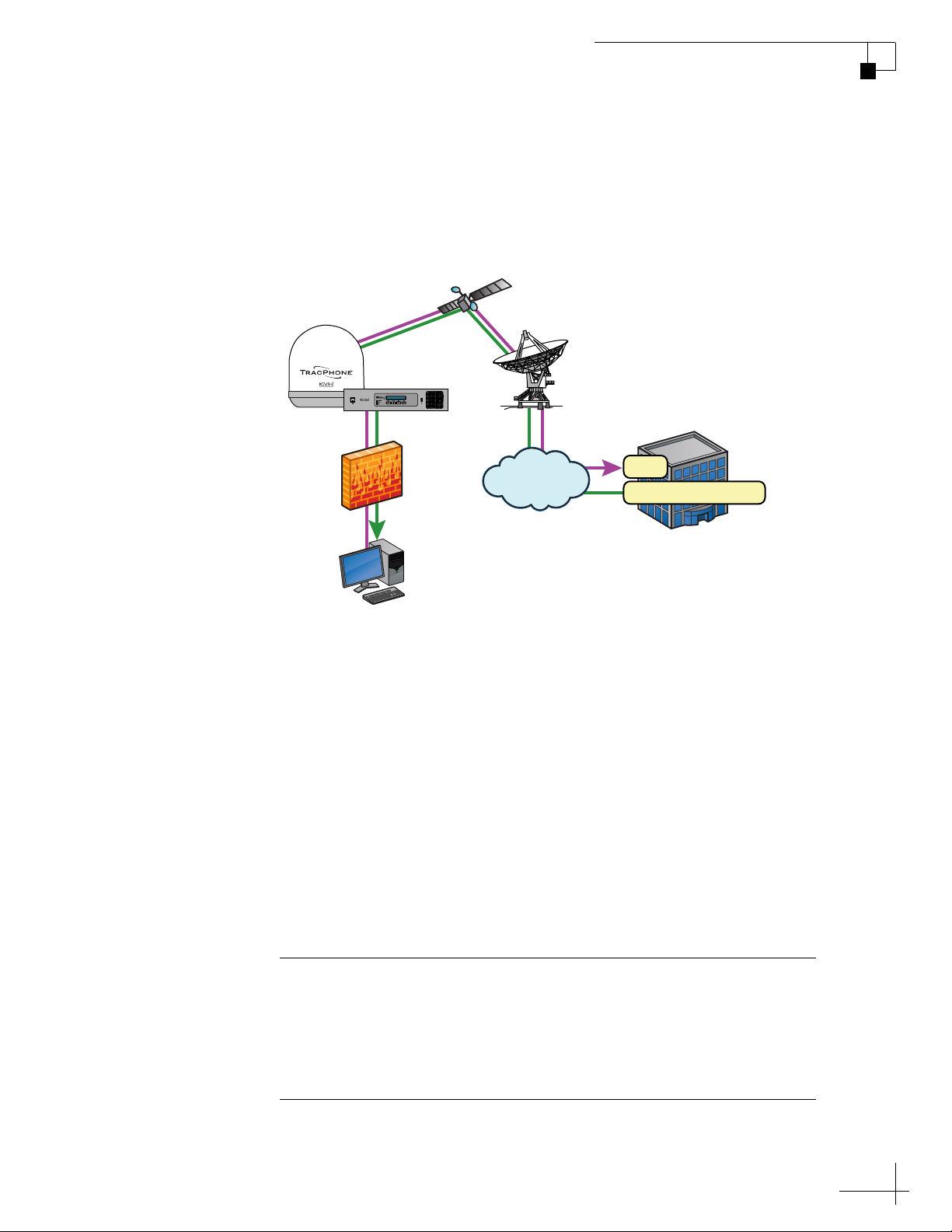
A static IP connection is commonly used by commercial vessels to
enable remote monitoring and IT management from shore, and to
allow a vessel’s crew to access their company’s secure VPN (virtual
private network).
Figure 6-9 Common Static IP Applications
Satellite
Tr acPhone
System
Hub
Firewall
Vessel Computer
Internet
VPN
Remote Monitoring
Fleet Headquarters
Setting Up a Static IP Connection
To establish a static IP network connection, follow these steps:
1. Make sure the system is activated for mini-VSAT Broadband
service.
2. Turn on the TracPhone system and make sure it is “Online.”
The system must remain online to allow KVH to set up your
system over the satellite link.
3. Fill out the online form at www.kvh.com/staticip. Be sure to
read all of the details on this form. An additional monthly fee
for static IP service will apply.
Important!
Only the “User Ethernet 4” port on the ICM can be used to connect
static IP devices, as this port bypasses the ICM’s local subnet to
connect directly to the built-in modem. Ports 1, 2, and 3 are configured
for DHCP addressing only.
61
Page 62
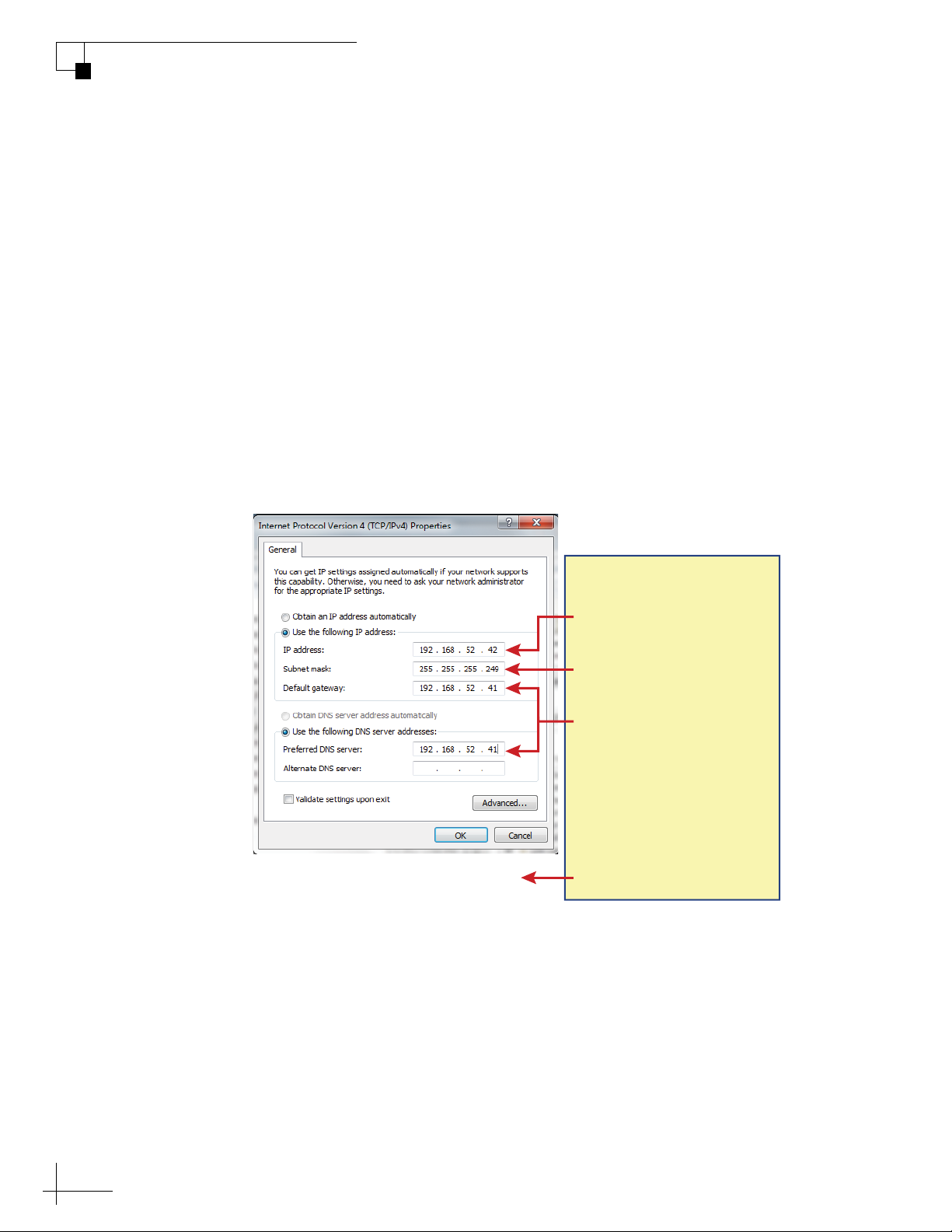
TracPhone V3-IP User’s Guide
IP address:
Private static IP address
From: KVH
To : Ve ssel Owner
Subnet mask:
Private static IP subnet mask
Default gateway &
Preferred DNS server:
Private static IP gateway
Public static IP addresses
IP addresses to access the vessel’s
computer remotely from shore
(one IP address per sub-region)
Network Configuration
4. Connect your network device or computer to the “User
5. At the TracPhone V3-IP web interface, select the Static IP
6. When you receive an e-mail from KVH confirming that your
Figure 6-10 Static IP Data
Ethernet 4” port on the rear panel of the ICM (see Figure 6-8 on
page 60). Use a straight-through CAT5 (or better) Ethernet
cable with RJ45 connectors.
physical Ethernet port configuration. Refer to “Physical
Ethernet Port Configurations” on page 66 for details.
static IP address has been set up, configure the TCP/IP
properties of your network device or computer with the static
IP data provided in the e-mail. For details on accessing your
computer’s TCP/IP properties, refer to “Configuring
Computers for DHCP” on page 55.
62
NOTE: A unique public static IP address is associated with each sub-region
in the region you requested. Therefore, users on shore must know where the
vessel is located and use its corresponding IP address to access the onboard
computer remotely.
Page 63

LAN Settings on ICM
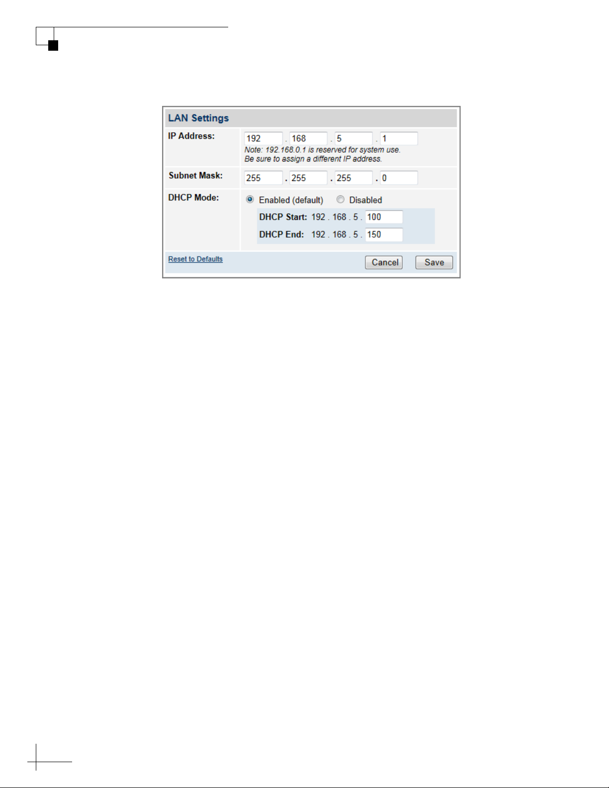
By default, the ICM has a gateway address of 192.168.5.1 and assigns
IP addresses in the 192.168.5.100-200 range (DHCP configurations
only). If this configuration conflicts with another onboard network,
you may change these settings.
Important!
The default LAN settings work well for most installations. Do not
change these settings unless absolutely necessary.
NOTE: If the optional CommBox software is enabled, or the ICM is
configured for Dual Dome-Secondary or Legacy mode, the Network Settings
page of the ICM will not contain any configurable fields. (See “CommBox
Features” on page 81 for details on enabling the CommBox software. See
“Physical Ethernet Port Configurations” on page 66 for details on changing
the ICM’s configuration.)
TracPhone V3-IP User’s Guide
Network Configuration
To change the ICM’s LAN settings, follow these steps:
1. At the TracPhone V3-IP web interface, click the Settings tab.
Then click Network Settings.
2. In LAN Settings, click Edit.
3. If the Login window appears, log in with the Administrator
password.
4. Modify the IP Address, Subnet Mask, and DHCP Mode
settings as necessary.
5. Click Save.
6. At the confirmation message, click Save.
63
Page 64
TracPhone V3-IP User’s Guide
Network Configuration
Figure 6-11 LAN Settings
64
Page 65
Cache Settings on ICM
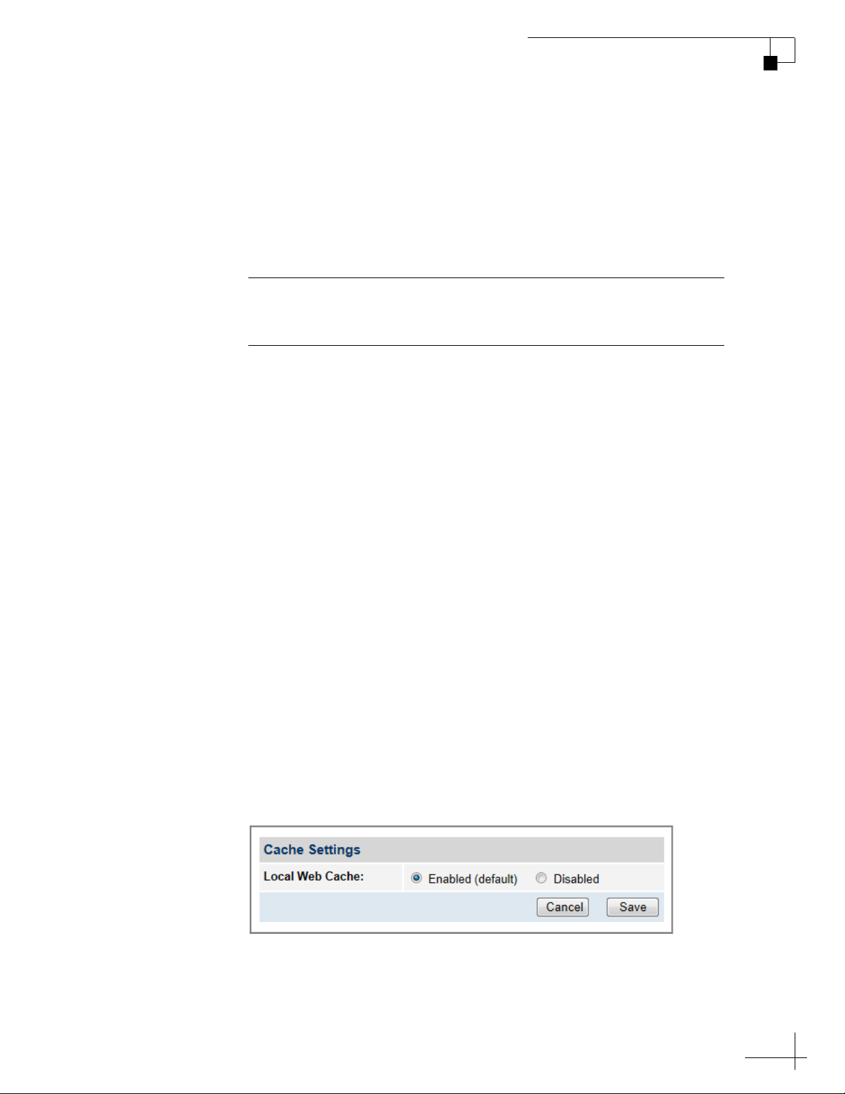
By default, the local web cache is enabled on the ICM. This feature
allows the ICM to temporarily store the content of web pages you visit,
so they will load faster on subsequent visits. The local web cache
should stay enabled to ensure the best possible web browsing
experience. However, it can be disabled if necessary.
Important!
Do not change the cache settings unless absolutely necessary.
NOTE: If the optional CommBox software is enabled, or the ICM is
configured for Dual Dome-Secondary or Legacy mode, the Network Settings
page of the ICM will not contain any configurable fields. (See “CommBox
Features” on page 81 for details on enabling the CommBox software. See
“Physical Ethernet Port Configurations” on page 66 for details on changing
the ICM’s configuration.)
TracPhone V3-IP User’s Guide
Network Configuration
To disable the local web cache on the ICM, follow these steps:
1. At the TracPhone V3-IP web interface, click the Settings tab.
Then click Network Settings.
2. In Cache Settings, click Edit.
3. If the Login window appears, log in with the Administrator
password.
4. Select Disabled.
5. Click Save.
6. At the confirmation message, click Save.
Figure 6-12 Cache Settings
65
Page 66

TracPhone V3-IP User’s Guide
Network Configuration
Physical Ethernet Port Configurations
By default, all four “User Ethernet” ports on the rear panel of the ICM
are set up for a standard LAN configuration – the ICM assigns IP
addresses to all devices connected to its network. However, at the
TracPhone V3-IP web interface, you can modify the ICM to support
any of the following alternate configurations:
• “Static IP Port Configuration” on page 67
• “Dual Dome Port Configuration” on page 68
• “Legacy Port Configuration” on page 69
Important!
If you select the Static IP, Dual Dome-Secondary, or Legacy
configuration, you will not be able to use minivsat.kvh to access the
web interface. You will need to enter the IP address of the ICM (default
is 192.168.0.9 in Static IP and Legacy modes, 192.168.0.10 in Dual Dome
-Secondary mode). In addition, if you select the Dual Dome-Secondary
or Legacy configuration, you will not be able to change any other
settings on the Network Settings page.
To select a physical Ethernet port configuration, follow these steps:
1. At the TracPhone V3-IP web interface, click the Settings tab.
Then click Network Settings.
2. In Physical Ethernet Port Configuration, click Edit.
3. If the Login window appears, log in with the Administrator
password.
66
Page 67
TracPhone V3-IP User’s Guide
Network Configuration
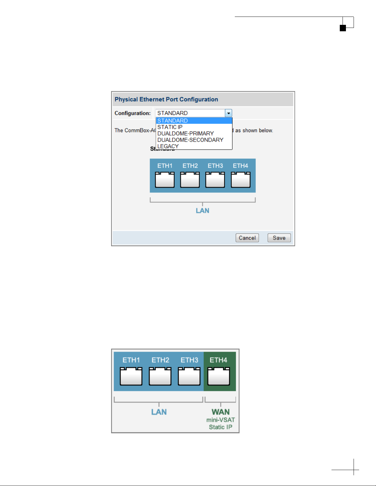
4. Select the desired configuration from the Configuration drop-
down menu. Then click Save.
Figure 6-13 Physical Ethernet Port Configuration Setting
5. At the confirmation message, click Save.
Static IP Port Configuration
In a static IP configuration, the “User Ethernet 4” port bypasses the
ICM’s local subnet to connect directly to the built-in modem. Ports 1, 2,
and 3 remain configured for the LAN. See “Static IP Configuration” on
page 60 for details.
Figure 6-14 Static IP Configuration
67
Page 68
TracPhone V3-IP User’s Guide
Network Configuration
Dual Dome Port Configuration
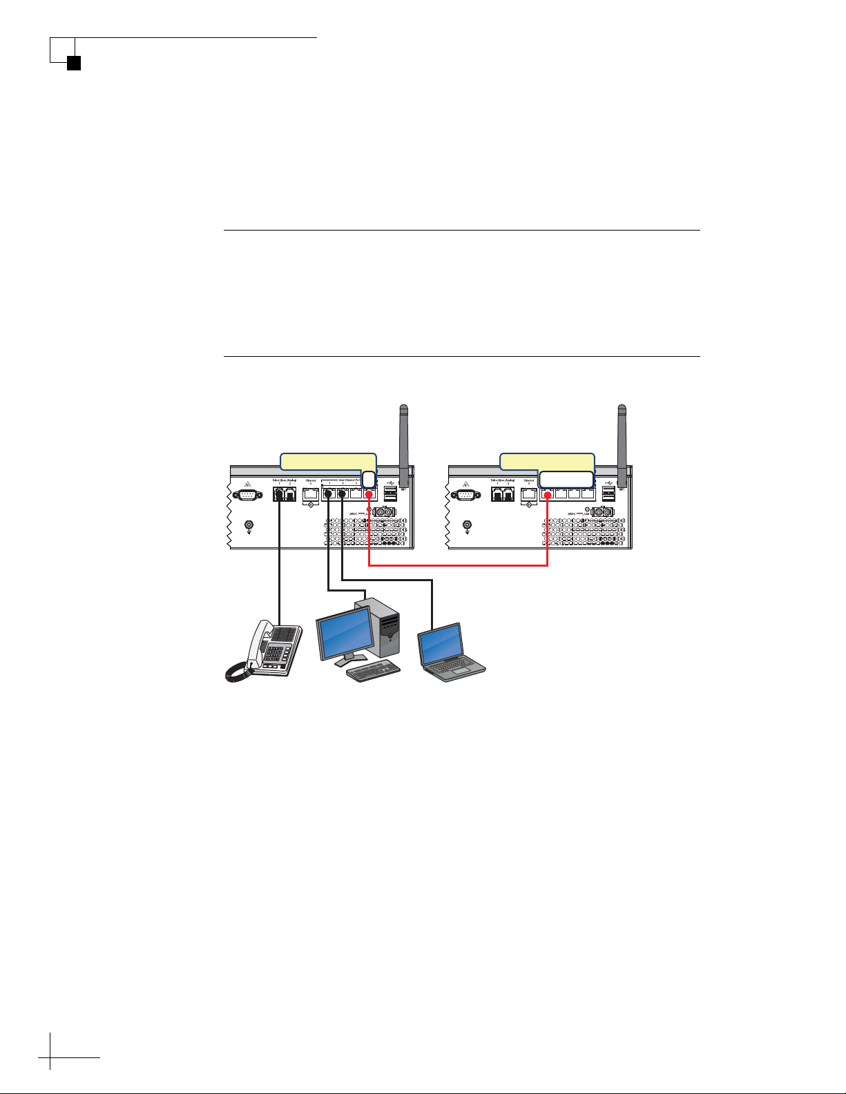
If a second TracPhone system is installed as a backup, one of the “User
Ethernet” ports on that secondary system’s ICM must be connected to
the “User Ethernet 4” port on the primary system’s ICM.
Important!
Contact KVH Technical Support before you configure the secondary
ICM (see “Technical Support” on page 110). KVH will need to modify
a setting on the secondary ICM over the air to support a dual dome
configuration.
Figure 6-15 Dual Dome Wiring (Example)
Primary System Secondary System
ICM
User Ethernet
4
Bridge PCShip Phone
ICM
Officers PC
User Ethernet
Any
In this dual-dome configuration, the vessel’s phones and network
devices connect to the primary system. The “User Ethernet 1, 2, and 3”
ports on the primary system’s ICM remain configured for the LAN.
The “User Ethernet” ports on the secondary system’s ICM are
configured as a bridge to the primary system’s ICM. Whenever the
primary system loses its connection to the mini-VSAT Broadband
service (e.g., its view of the satellite becomes blocked), all voice and
data traffic will automatically get routed through the “User Ethernet
4” port to the secondary system.
68
Page 69
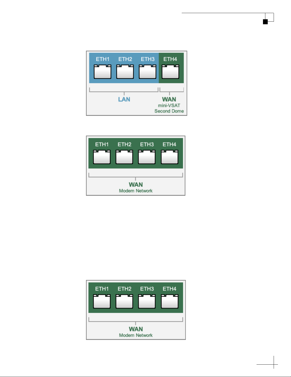
Figure 6-16 Dual Dome-Primary Configuration
Figure 6-17 Dual Dome-Secondary Configuration
TracPhone V3-IP User’s Guide
Network Configuration
Legacy Port Configuration
Use the legacy configuration only if the ICM is replacing an older
TracPhone V7 or V3 antenna system’s belowdecks equipment. Do not
use this mode with a TracPhone V3-IP, V7-IP, V11, or V11-IP antenna
system.
In a legacy configuration, many of the ICM’s features are disabled to
make the configuration similar to a standard TracPhone V7 or V3.
Figure 6-18 Legacy Configuration
69
Page 70
TracPhone V3-IP User’s Guide
Network Configuration
CommBox Settings on ICM
If the optional CommBox software is enabled, the ICM’s network
settings are configured by KVH over the air. The Network Settings
page of the ICM will not contain any configurable fields.
NOTE: See “CommBox Features” on page 81 for details on enabling the
CommBox software.
For complete details about the CommBox software, refer to the
CommBox manual. To view the CommBox manual, follow these steps:
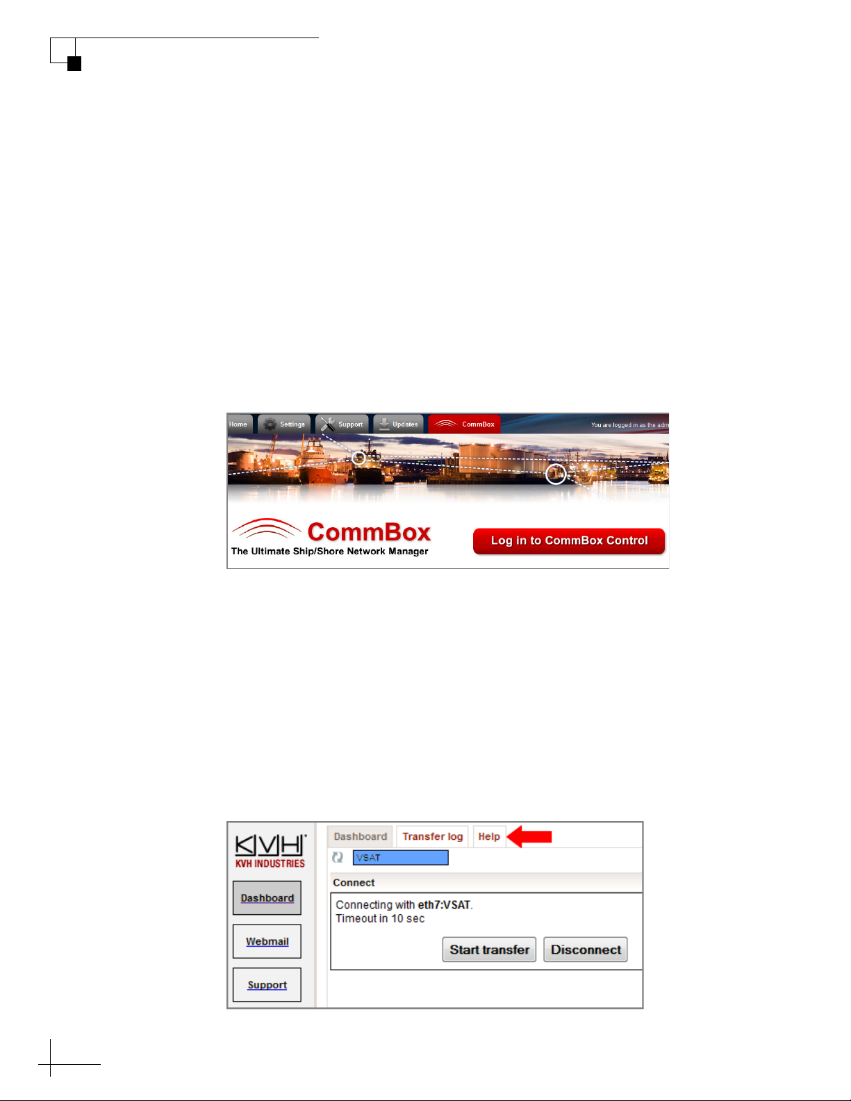
1. At the TracPhone V3-IP web interface, click the CommBox tab.
Figure 6-19 CommBox Tab
2. Click Log in to CommBox Control.
3. Log into the CommBox web page with your CommBox user
name and password.
NOTE: The CommBox user name and password differs from the ICM’s
Administrator password.
4. At the CommBox web page, click the Help tab.
Figure 6-20 CommBox Help Tab
70
Page 71

Reset to Factory Configuration
If the system’s network becomes corrupted such that you can no
longer access the TracPhone V3-IP web interface, you can reset the
system to its original factory settings.
Important!
Perform a factory reset only if directed by KVH Technical Support.
This function should only be used as a last resort when all other
options fail.
The following settings are included in the reset:
• Reverts to Standard (DHCP) physical Ethernet port configuration
• Deletes any custom CommBox configurations
TracPhone V3-IP User’s Guide
Network Configuration
• Clears any configured no-transmit zones
• Sets the ICM’s LCD brightness to High
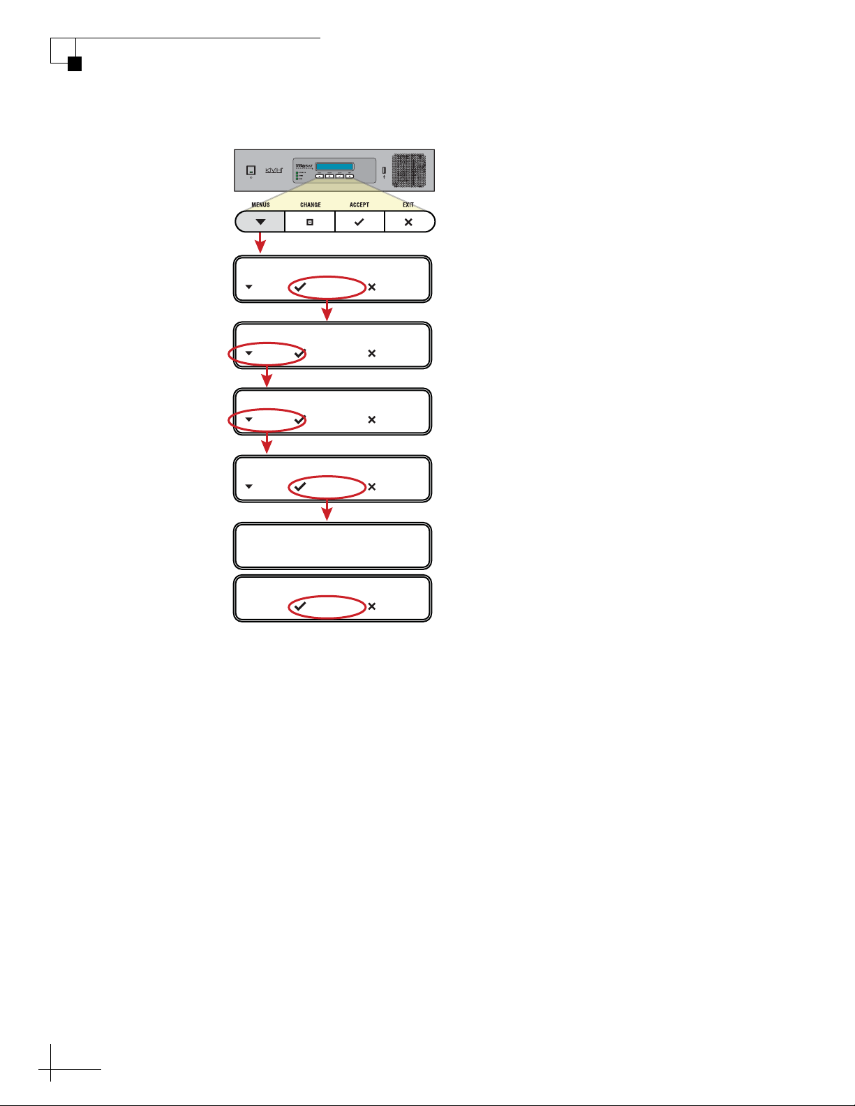
To reset the system to its factory settings, follow these steps:
1. At the ICM’s front panel, press MENUS until the display
shows “DIAGNOSTIC TOOLS.”
2. Press ACCEPT.
3. At “KVH SUPPORT IP,” press NEXT.
4. At “CALIBRATE GYROS,” press NEXT.
5. At “FACTORY RESET,” press ACCEPT.
6. At “PROCEED WITH RESET?,” press ACCEPT.
The system reverts to its original factory settings. Do not power off the
system while this reset is in progress.
71
Page 72
TracPhone V3-IP User’s Guide
DIAGNOSTIC TOOLS
NEXT SELECT EXIT
KVH SUPPORT IP
NEXT SELECT EXIT
CALIBRATE GYROS
NEXT SELECT EXIT
NETWORK CONFIG WILL
BE ERASED!
PROCEED WITH RESET?
SELECT EXIT
Press MENUS until
DIAGNOSTIC TOOLS
is displayed.
FACTORY RESET
NEXT SELECT EXIT
Network Configuration
Figure 6-21 Factory Reset
72
Page 73

TracPhone V3-IP User’s Guide
7. Data Connections
This section explains how to connect to the Internet via the mini-VSAT
Broadband service. It also provides a number of suggestions for
minimizing the amount of data that’s transferred over the network.
Contents
Internet Access Overview................................................ 75
Tips for Minimizing Data Usage....................................... 76
CommBox Features ......................................................... 81
Data Connections
73
Page 74

Internet Access Overview
While the TracPhone system is online with the mini-VSAT Broadband
service, you can perform all of the same Internet tasks you perform at
home:
•E-mail
•Web browsing
• Weather and chart updates
• Instant messages
• Corporate network access (VPN)
• Data transfers
TracPhone V3-IP User’s Guide
Data Connections
Important!
High-bandwidth applications, such as peer-to-peer file sharing, web
cameras, streaming media, and high-speed gaming, are not
supported by fixed rate plans. For details, be sure to read all of the
service terms and conditions in the End User Agreement, which can
be found at www.kvh.com/mvbcustomercenter.
Connecting to the Internet
To connect to the Internet, follow these steps:
1. Make sure the TracPhone system is online.
2. Open a web browser window on any computer connected to
the network.
3. If you’re unable to connect, make sure your computer is
configured for DHCP addressing. Refer to “Configuring
Computers for DHCP” on page 55.
75
Page 75

TracPhone V3-IP User’s Guide
Data Connections
Tips for Minimizing Data Usage
The configurations of operating systems, web browsers, and
applications generally assume an unlimited, always-on broadband
connection. As such, they will often try to connect to the Internet on
their own to download updates and transfer files. They will also
operate without any regard to the amount of traffic they generate to
perform routine tasks.
While high data usage is not much of a concern with a broadband
connection on shore, avoiding excessive data usage is worthwhile
when using the mini-VSAT Broadband service at sea, especially if you
are charged by the megabyte on a metered rate plan.
NOTE: Installing network monitoring software on your computer(s) will
allow you to keep track of how much data is downloaded to and uploaded from
your computer(s). For the ultimate suite of network management tools, look
no further than KVH’s CommBox software – see “CommBox Features” on
page 81 for details!
Consider the guidelines in this section to eliminate unnecessary
background Internet activity and minimize the amount of data you
consume. Adopting these guidelines will help ensure you use the
service in the most efficient and cost-effective manner.
Important!
You are responsible for all data transferred to/from your network
devices, including inadvertent downloads by applications running in
the background.
76
Page 76

Preventing Automatic Updates
The default configuration of many applications allow them to
download updates from the Internet automatically, without any user
interaction. KVH recommends that, while the device is being used at
sea, you set up these applications either to not check for updates or to
notify you before downloading them. These applications include:
•Anti-virus software
• Spyware protection software
•Web browser
• Mobile apps
TracPhone V3-IP User’s Guide
Data Connections
• Adobe Acrobat
• Apple iTunes
®
®
Reader
• Windows Update or Mac Software Update
NOTE: Android devices offer a “Restrict Background Data” setting, which
will prevent background updates from all installed apps.
Any malicious applications hidden on your device may also use your
Internet connection without your knowledge. Therefore, prior to using
your device onboard the vessel, run a full system scan with an up-todate anti-virus and spyware detection/removal utility.
Disabling Automatic File Backup and Synchronization
The default configuration of many cloud-based file sharing and
syncing tools allow them to upload files (including photos, videos, and
other media) and synchronize mobile devices without any user
interaction. KVH recommends that, like preventing automatic
updates, you set up these services for manual backup and
synchronization only. These cloud storage services include:
• Apple iCloud
• Google Drive
®
™
• Microsoft SkyDrive
•Dropbox
™
•Box
®
77
Page 77

TracPhone V3-IP User’s Guide
Data Connections
Firewall Protection
A firewall can prevent most applications from accessing the Internet
without your knowledge, as well as protect your devices from outside
intrusion. KVH recommends that you enable the firewall on your
router or individual network devices.
Web Browser Settings
All popular web browsers, such as Internet Explorer, Mozilla Firefox,
Google Chrome, and Apple Safari, offer various tools that allow you to
minimize the amount of data they consume. Consider these options:
Limit Multimedia Downloads
Set up your browser to disable multimedia content embedded in
websites from playing automatically.
Enable Pop-Up Blocker
Many consumer websites overlay small pop-up windows over the
main page to launch ads. Turn on your web browser’s pop-up blocker
to prevent these from running and consuming data. Your web browser
might also offer tools to block websites or types of content that you
specify, or allow access to only certain websites that you trust.
Maximize Caching of Web Pages
By default, web browsers automatically refresh the content they have
stored in their cache. If the browser finds a new version of a website is
available, it will delete the version it has stored locally and download
the new one. KVH recommends you set up your browser to download
new versions of web pages only when you visit them, and also
increase the size of the cache to the maximum level permitted for your
browser.
Disable Preloading of Web Pages
The mobile version of Google Chrome (the default browser on
Android devices) speeds up web browsing by preloading the
destination web pages of links shown on the currently viewed page.
This feature consumes an enormous amount of data and should be
disabled.
78
Avoid Multiple Browsing Tabs
KVH recommends that you browse the web using a single open
browser tab. Any tabs left open in the background may continue to
consume data.
Page 78

Data-Intensive Applications
The following applications can consume a great deal of data whenever
they are active or running in the background:
• Skype (uses 40 MB per month just to maintain your status, in addition
to the data used for actual calls and chats)
• RSS feeds and widgets presenting real-time information (e.g., news,
weather, stocks ticker, sports scores, etc.)
•Social media (e.g., YouTube and Facebook)
• Peer-to-peer (P2P) file sharing (e.g., BitTorrent, Gnutella, etc.)
If you are charged by the megabyte on a metered rate plan, use caution
when running these types of applications to help prevent unpleasant
surprises on your airtime bill.
TracPhone V3-IP User’s Guide
Data Connections
Important!
Some high-bandwidth applications, such as peer-to-peer file sharing,
web cameras, streaming media, and high-speed gaming, are not
supported by fixed rate plans. For details, be sure to read all of the
service terms and conditions in the End User Agreement, which can
be found at www.kvh.com/mvbcustomercenter.
Mobile Websites
Many organizations now offer alternative versions of their websites
optimized for mobile devices. Although designed for smartphone
users on a cellular connection, you can access these mobile websites on
a desktop or laptop as well. KVH recommends you visit mobile
websites instead of full sites whenever possible to minimize the
amount of data used.
To view the mobile version of a website, simply replace the “www” in
the address with an “m”. For example, to view the mobile version of
CNN’s website, you would enter “m.cnn.com” in your web browser.
Disabling Wi-Fi Access on Mobile Devices
If you don’t intend to use your mobile device to access the Internet
over the mini-VSAT Broadband service, disable the mobile device’s
automatic Wi-Fi connection to the ICM’s wireless network.
79
Page 79

TracPhone V3-IP User’s Guide
Data Connections
E-mail Best Practices
There are several ways to reduce the amount of data your e-mail
application uses. Consider the following e-mail best practices:
• Use an IMAP (Interactive Mail Access Protocol) server instead of
• Disable automatic sending/receiving of new mail.
• Send messages in plain text rather than HTML format.
• Compress all attachments.
• Disable automatic signatures and read receipts.
traditional POP3 (Post Office Protocol 3).
80
Page 80

CommBox Features
The optional CommBox software extends the network capabilities of
the ICM to improve crew morale, streamline operations, improve
efficiency, and reduce costs. Two options are available:
• CommBox Standard Bundle (KVH part no. 35-0010): Provides
least cost routing, onboard firewall, web caching, web image
compression, ad removal, and URL and content filtering
• CommBox Enterprise Bundle (KVH part no. 35-0011): Provides
everything included in the Standard bundle, plus automated file
transfers, differential synchronization, mail relay server, web mail
client, anti-spam and anti-virus filters, roaming crew accounts, and
prepaid Internet and e-mail services
NOTE: The CommBox Enterprise Bundle requires integration with a
CommBox hub.
TracPhone V3-IP User’s Guide
Data Connections
Purchasing a CommBox Bundle
To learn more about CommBox’s powerful suite of network
management features, go to the TracPhone V3-IP web interface and
click the CommBox tab. Then contact KVH Network Services at
[email protected] for a consultation. KVH will coordinate
with you to select, install, and configure the appropriate bundle to
meet your needs.
Accessing the CommBox Web Interface
If a CommBox software bundle is enabled on the ICM, follow these
steps to access the CommBox web interface:
1. At the TracPhone V3-IP web interface, click the CommBox tab.
Figure 7-1 CommBox Tab
81
Page 81
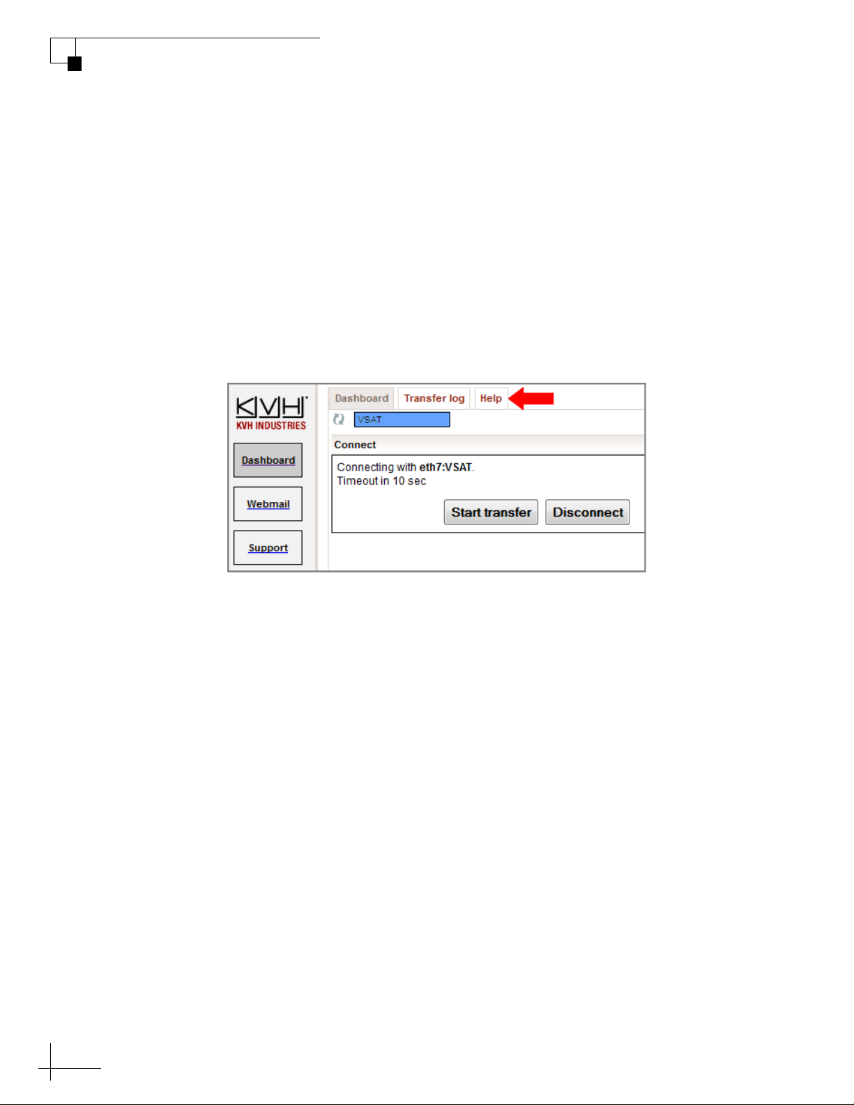
TracPhone V3-IP User’s Guide
Data Connections
2. Click Log in to CommBox Control.
3. Log into the CommBox web interface with your CommBox
NOTE: The CommBox user name and password differs from the ICM’s
Administrator password.
For more details about how to use the CommBox, refer to the
CommBox manual available on the Help tab of the CommBox web
interface.
Figure 7-2 CommBox Help Tab
user name and password.
82
Page 82

TracPhone V3-IP User’s Guide
8. Troubleshooting
This section identifies some basic problems along with their possible
causes and solutions. It also explains what the error messages, status
messages, and LED conditions indicate, how to view and export the
system logs, and how to get technical support.
Contents
Initial Steps for Any Problem ........................................... 85
Troubleshooting a Voice Problem.................................... 87
Troubleshooting a Data Problem ..................................... 89
Troubleshooting
Error Messages ............................................................... 91
Status Information........................................................... 94
LED Indicators ............................................................... 104
System Logs .................................................................. 106
Equipment ID Numbers.................................................. 108
Software Versions ......................................................... 109
Technical Support.......................................................... 110
83
Page 83

Initial Steps for Any Problem
If you are experiencing a problem with your TracPhone system, first
follow these basic steps:
Step 1a: Check System Status Information on the Web Interface
Open a web browser window on any computer on the network and
enter http://minivsat.kvh to access the TracPhone V3-IP web interface.
NOTE: This web address may not work on all platforms and browsers. It also
will not work in certain network configurations. If the web interface does not
appear, enter the ICM’s IP address instead (default is 192.168.5.1). You can
find this address on the ICM front panel LCD (go to Settings > Network
Settings > IP Assignments).
The Home page provides system status information. Check the
following:
TracPhone V3-IP User’s Guide
Troubleshooting
• Connection Status: “Online” indicates the system is connected to
the mini-VSAT Broadband service.
• Antenna State: “Tracking” indicates the antenna is tracking the
satellite.
• My Phone: “Online & Ready” indicates the ICM’s built-in MTA is
connected to the enhanced voice service.
If a status message differs from the normal indications listed above,
refer to “Status Information” on page 94. If an error message is
displayed, refer to “Error Messages” on page 91.
Step 1b: Check System Status Information on the ICM Front Panel
If you are unable to connect to the web interface, you can find similar
status information on the front of the ICM. Check the following:
• ICM LCD: “Online Tracking” indicates the system is connected to
the mini-VSAT Broadband service and the antenna is tracking the
satellite.
• LEDs: All LEDs should be lit green.
If a status message differs from the normal indication listed above,
refer to “Status Information” on page 94. If an error message is
displayed, refer to “Error Messages” on page 91. If an LED is not lit
green, refer to “LED Indicators” on page 104.
85
Page 84

TracPhone V3-IP User’s Guide
Troubleshooting
Step 2: Check for Blockage
If the antenna is continuously searching for the satellite, check the area
around the antenna for blockage. The antenna needs an unobstructed
view of the sky to receive satellite signals. Common causes of blockage
include other onboard masts or structures, severe weather, and nearby
buildings, bridges, trees, or other vessels.
NOTE: You can determine which direction the antenna is pointing by
viewing the Home page on the web interface or the “CURRENT AZ/EL”
status message on the ICM front panel LCD (go to Status > Antenna/ACU
Status> Current Az/El).
If there is no blockage, you might be located outside of the mini-VSAT
Broadband service coverage area (for a coverage map, visit
www.kvh.com/minivsatmap).
Step 3: Try Accessing the KVH Test Page
Try accessing the KVH test page at http://208.83.165.11/mbbtest. If
the KVH test page appears in your browser, but you still can’t access
any other web page, there might be an account or hub issue – contact
KVH Technical Support (see “Technical Support” on page 110).
Step 4: Check Power and Cables
Make sure power is applied to all system components. Also make sure
all cables are connected tightly.
Step 5: Restart the System
Try restarting the system at the TracPhone V3-IP web interface (see
“Hardware Restart” on page 127). If you cannot access the web
interface, turn off the ICM at the front panel, then turn it back on.
86
Page 85

Troubleshooting a Voice Problem
If you are unable to make a voice call, follow these steps:
Step 1: Check the Basics
Complete the initial steps described in “Initial Steps for Any Problem”
on page 85.
Step 2: Make Sure You Are Dialing the Number Properly
As explained in “Making a Ship-to-Shore Call” on page 40, if you are
dialing a number outside the country assigned to Line 1, you need to
dial the appropriate international prefix and country code, in addition
to the area/city code and local phone number. For example, if your
Line 1 is assigned a United States phone number and you are calling a
number outside of the U.S., you need to dial 011 + Country Code +
Area Code + Local Phone Number.
TracPhone V3-IP User’s Guide
Troubleshooting
Step 3: Check the My Phone Status on the Web Interface
At the TracPhone V3-IP web interface, go to the Home page and check
the My Phone status information. If it shows “Unable to Register Voice
Service,” there is an account or activation issue - contact KVH
Technical Support (see “Technical Support” on page 110). The My
Phone status also shows the status of the phone line.
Step 4: Restart the MTA
The MTA built into the ICM might need to download an updated
configuration file from the network. Try restarting the MTA at the
TracPhone V3-IP web interface (see “Hardware Restart” on page 127).
Step 5: Verify the MTA Obtained an IP Address
The MTA built into the ICM must receive an IP address from the ICM
in order to provide a voice connection. Pick up the handset on any
phone connected to the ICM and press ***1 on the keypad. If you hear
“0.0.0.0” in the handset, the MTA did not receive a valid IP address.
Contact KVH Technical Support for assistance (see “Technical
Support” on page 110).
87
Page 86

TracPhone V3-IP User’s Guide
Troubleshooting
Step 6: Try a Different Phone
Disconnect the phone from the ICM and connect another phone in its
place (use a phone that you know is working properly). If you are then
able to place a call with the new phone, the phone you were using is
faulty.
Step 7: Verify the Phone Is Connected Properly
Make sure your phone is connected to the RJ11 “Voice Line 1” jack on
the ICM. Do not use the “Voice Line 2” jack. Only “Voice Line 1” is
enabled for use.
88
Page 87

Troubleshooting a Data Problem
If you are unable to access the Internet, follow these steps:
Step 1: Check the Basics
Complete the initial steps described in “Initial Steps for Any Problem”
on page 85.
Step 2: Check Your Computer’s DHCP Configuration
Unless you have set up a static IP address, your computer’s TCP/IP
settings need to be configured for DHCP addressing, which allows the
ICM to assign it an IP address. Refer to “Configuring Computers for
DHCP” on page 55 for details.
Step 3: Try a Direct Wired Connection
TracPhone V3-IP User’s Guide
Troubleshooting
Connect your computer directly to the “User Ethernet 1” port on the
back of the ICM using an Ethernet cable. Then restart your computer.
If you are now able to access the Internet, there is a problem with your
vessel’s network.
Step 4: Ping the Network Connections
The Ping command sends a test packet to any IP address you choose
and reports how long it takes to receive a response.
To send a Ping on a Windows PC:
Open a Command Prompt window (press Windows Logo key + R, then
type cmd). Then, at the command prompt, type ping <IP address>.
To send a Ping on a Mac:
Open the Network Utility (go to Finder > Utilities > Network Utility).
Then, in the Ping tab, type the IP address then click Ping.
Ping the IP address of the ICM. You can find the IP address on the
front panel LCD (go to Settings > Network Settings > IP Assignments).
The default IP address is 192.168.5.1. All packets sent should be
received. If packets are lost, your computer is not connected properly
to the ICM.
Ping 4.2.2.1 to check your connection to the Internet. All packets sent
should be received within 580-900 ms. If the ping fails, contact KVH
Technical Support (see “Technical Support” on page 110).
89
Page 88
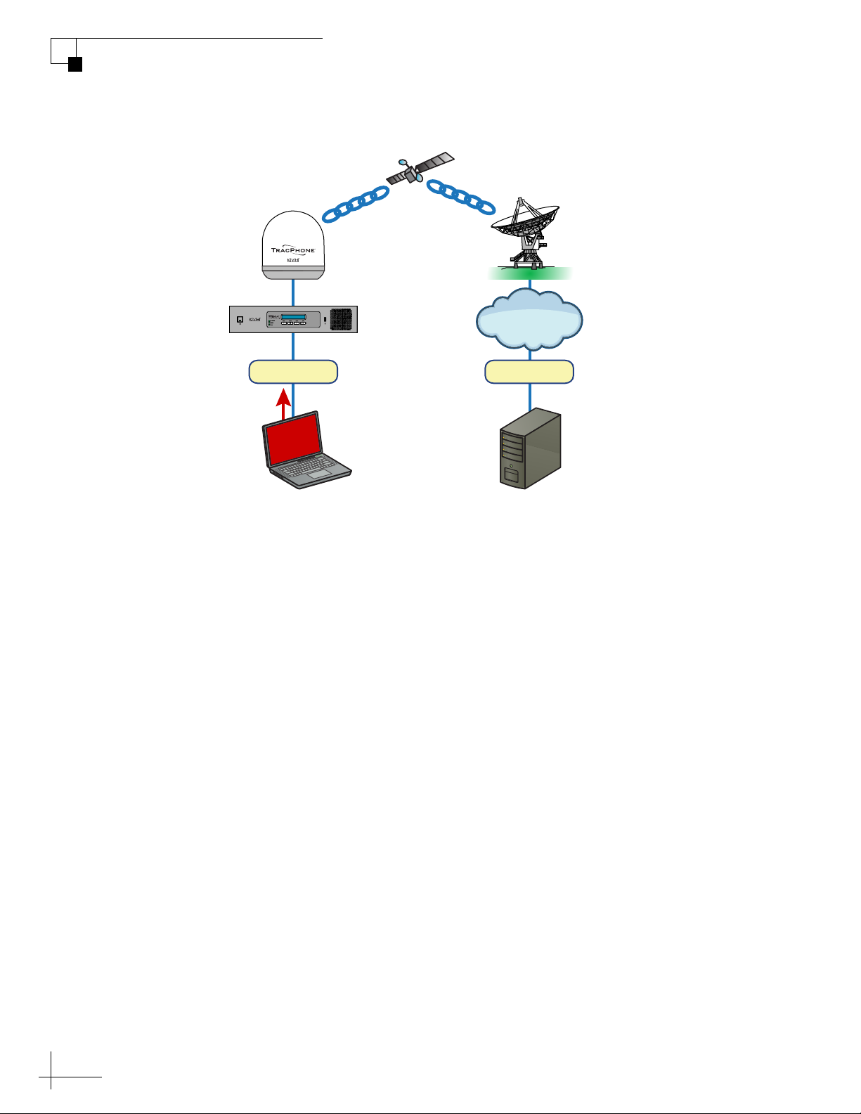
TracPhone V3-IP User’s Guide
Antenna
System
PC
Satellite
Hub
Internet
DNS Server
P
IN
G
192.168.5.1
4.2.2.1
Troubleshooting
Figure 8-1 Pinging the Network Connections
90
Page 89

Error Messages
This section lists the error message codes that might appear on the
TracPhone V3-IP web interface and front panel LCD to indicate a
system problem. Many of these faults should only be repaired by a
KVH-certified technician; contact KVH Technical Support for
assistance (see “Technical Support” on page 110).
Error Description
100 There is an open circuit in the antenna power/data cable.
Check the cable.
101 There is a short circuit in the antenna power/data cable.
Check the cable.
102 The ICM is not providing the proper DC power to the
antenna. Check the wires on the back of the ICM.
TracPhone V3-IP User’s Guide
Troubleshooting
103 A software update file was not found on the USB device.
Try these steps:
• Remove the USB device from the ICM, wait 10 seconds,
then reinsert it.
• Verify that a valid TracPhone V3-IP update file (ending
in “.kvh”) is present on the USB device.
• Replace the update file on the USB device with a new file.
• Use a different USB device.
104 The software update file you selected is corrupt. Try a new
update file.
105 The ICM is unable to read from or write to its internal
memory (EEPROM). Contact KVH.
106 The ICM has lost communications with the antenna. Try
these steps:
• Check the wiring on the back of the ICM.
• Check the antenna power/data cable.
• Try turning the system off, then back on.
107 The ICM’s internal temperature exceeds acceptable limits.
Try these steps:
• Listen for the cooling fan inside the ICM. If you don’t
hear the fan, contact KVH.
• If you hear the cooling fan, turn off the system and allow
it to cool down. Then vacuum the ICM’s vents (see
“Preventive Maintenance” on page 113).
• If the problem persists, you might need to relocate the
unit to an area that provides better ventilation.
91
Page 90

TracPhone V3-IP User’s Guide
Troubleshooting
Error Description
111 The ICM is unable to initialize its built-in wireless access
112 There is an internal fault in the ICM. Contact KVH.
117 There is an open circuit in the BUC power cable (ICM
118 There is a short circuit in the BUC power cable (ICM
120 The internal temperature of the ICM’s built-in modem
point (WAP). Contact KVH.
jumper cable between C1 and C2) or the transmit (TX) RF
cable. Check the cables. If the cables are OK, the BUC might
be faulty – contact KVH.
jumper cable between C1 and C2) or the transmit (TX) RF
cable. Check the cables. If the cables are OK, the BUC might
be faulty – contact KVH.
exceeds acceptable limits. Try these steps:
• Listen for the cooling fan inside the ICM. If you don’t
hear the fan, contact KVH.
• If you hear the cooling fan, turn off the system and allow
it to cool down. Then vacuum the ICM’s vents (see
“Preventive Maintenance” on page 113).
• If the problem persists, you might need to relocate the
unit to an area that provides better ventilation.
92
121 The ICM is not receiving satellite signal strength (RSSI)
data from its built-in modem. Try these steps:
• Turn the ICM off, then back on.
• Check the serial data jumper cable on the back of the ICM
connecting between A1 and A2.
122 The ICM’s built-in modem is not communicating. Try these
steps:
• Check the ICM jumper cables.
• Try turning the ICM off, then back on.
• If the error persists, contact KVH.
123 The ICM’s built-in modem is not responding to status
queries. Contact KVH.
124 The software update file you selected is not valid for the
TracPhone V3-IP. Try a new update file.
127 The antenna is not accepting the no-transmit zones setup
from the ICM. Contact KVH.
128 The software update failed. Retry updating the software. If
it fails again, check the power/data cable and the wires on
the back of the ICM.
Page 91
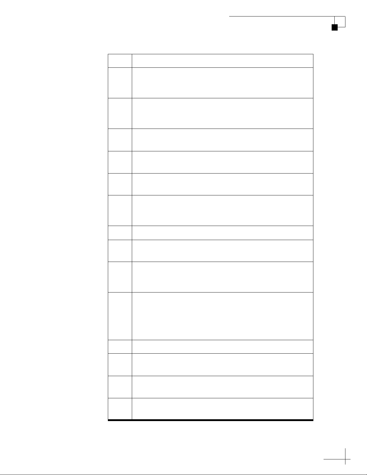
TracPhone V3-IP User’s Guide
Troubleshooting
Error Description
200 The antenna is not receiving adequate DC power from the
ICM. Check the power/data cable and the wires on the
back of the ICM.
204 The antenna’s main board has lost RF communications. Try
updating the software (see “Software Updates” on
page 114).
206 The antenna’s azimuth motor or limit switch failed. Contact
KVH.
208 The antenna’s elevation motor or limit switch failed.
Contact KVH.
218 The antenna’s skew motor or limit switch failed. Contact
KVH.
219 One of the antenna’s gyros is out of calibration. Try
recalibrating the gyros (see “Gyro Calibration” on
page 125). If a gyro fails to calibrate, contact KVH.
220 One of the antenna’s gyros failed. Contact KVH.
221 The system is not receiving any data from the GPS. Contact
KVH.
222 The antenna’s internal temperature exceeds acceptable
limits. Turn off the system and allow it to cool. If the
problem persists, contact KVH.
234 The antenna is not receiving satellite signal strength (RSSI)
data from the ICM. Try these steps:
• Turn the ICM off, then back on.
• Check the wires on the back of the ICM.
• Check the power/data cable.
235 The antenna has lost RF communications. Contact KVH.
240 The antenna’s LNB is not receiving the proper power from
the ICM’s receive (RX) RF cable. Check the RX RF cable.
241 The antenna’s main board detects a power failure. Contact
KVH.
265 The GPS is unable to acquire a fix. Check for blockage or RF
interference around the antenna.
93
Page 92
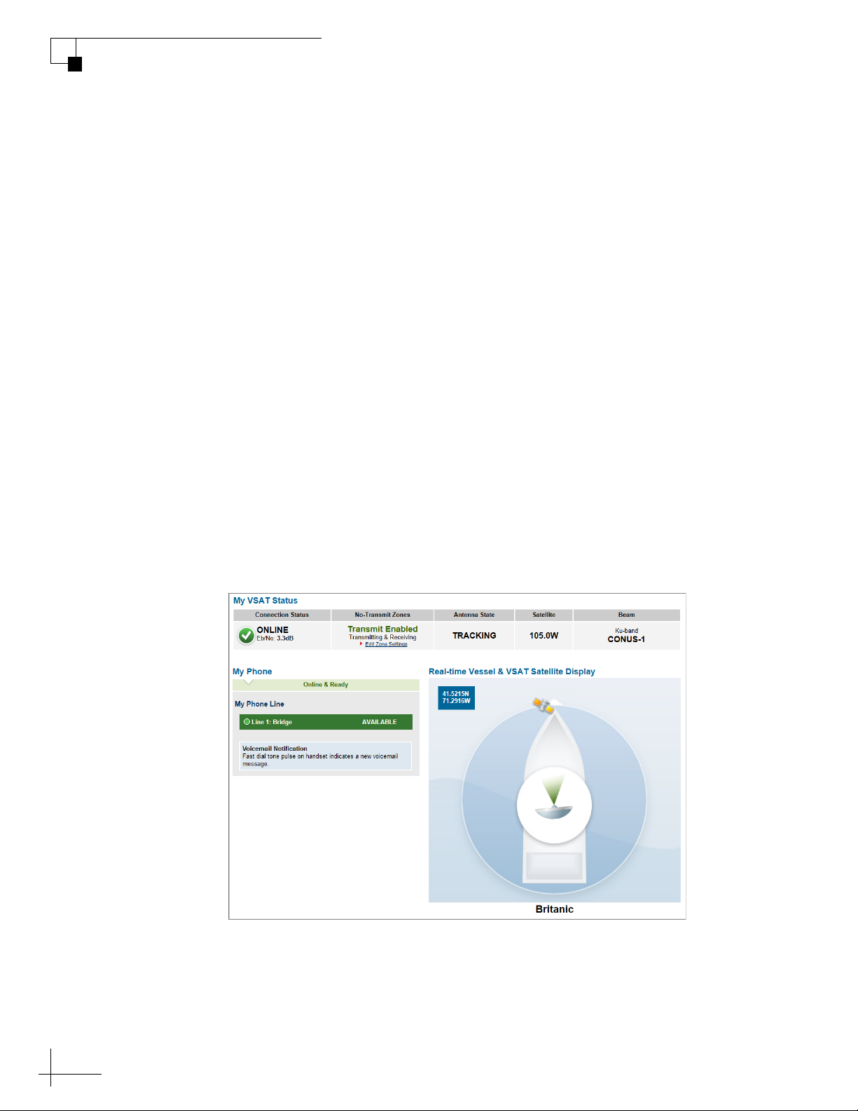
TracPhone V3-IP User’s Guide
Troubleshooting
Status Information
You can find system status information on the TracPhone V3-IP web
interface and front panel LCD. Similar information is available in both
places. See the following for details:
• “Status Information on the Web Interface”
• “Status Information on the ICM Front Panel LCD” on page 100
Status Information on the Web Interface
On the TracPhone V3-IP web interface, you can view status
information on the following pages:
• Home page (see “Home Page of the Web Interface”)
• Support page (see “Support Page of the Web Interface” on
page 97).
Home Page of the Web Interface
The Home page provides basic system status information.
Figure 8-2 Home Page
94
The tables below summarize the status information that is available on
the Home page.
Page 93

TracPhone V3-IP User’s Guide
Troubleshooting
My VSAT Status
Message Description
Connection Status General status of the ICM’s built-in modem:
• Online – Modem is connected to the miniVSAT Broadband service; the system is
ready for use
•Initializing
• Waiting for Hub Comm – Modem is
waiting for the antenna to lock onto the
satellite
• Attempting Login – Modem is attempting
to log into the mini-VSAT Broadband
service
• Offline – Modem is not connected to miniVSAT Broadband
• Updating – Modem is downloading new
software or satellite configuration files
Eb/No: Quality of the received satellite
signal; Eb/No = Energy per bit/noise power
per Hertz
No-Transmit Zones
(if zones are set up)
Status of the no-transmit zones:
• Transmit Enabled (green) – Antenna is not
pointing within a no-transmit zone
• Transmit Disabled (orange) – Antenna is
pointing within a no-transmit zone; zones
are being enforced
• Transmit Enabled (red) – No-transmit
zones are being ignored; antenna can
transmit without restriction
Antenna State General status of the antenna:
•Tracking
•Initializing
• Searching
• Cable Unwrap – Unwrapping the internal
cable; the cable can wrap up to 710°
• Waiting for Modem
•Idle
•Error
Satellite Satellite that the modem has currently
selected for tracking
Beam Beam of the satellite currently selected for
tracking
95
Page 94

TracPhone V3-IP User’s Guide
Troubleshooting
My Phone
Message Description
My Phone General status of the system’s connection to
Line 1 General status of the phone line:
the enhanced voice service:
• Online & Ready – the voice service is
ready for use
• Offline
• Logging In...
• Unable to Connect to Voice Service –
Caused by an account or activation error;
also displayed during system startup
• Available (green) – the phone line is ready
for use
• Dialing (green)
• Off Hook (green)
•Ringing (green)
• In Use (orange) – Phone call in progress
• Unavailable (gray)
For details on the Real-time Vessel & VSAT Satellite Display, refer to
“Understanding the Home Page” on page 19.
96
Page 95
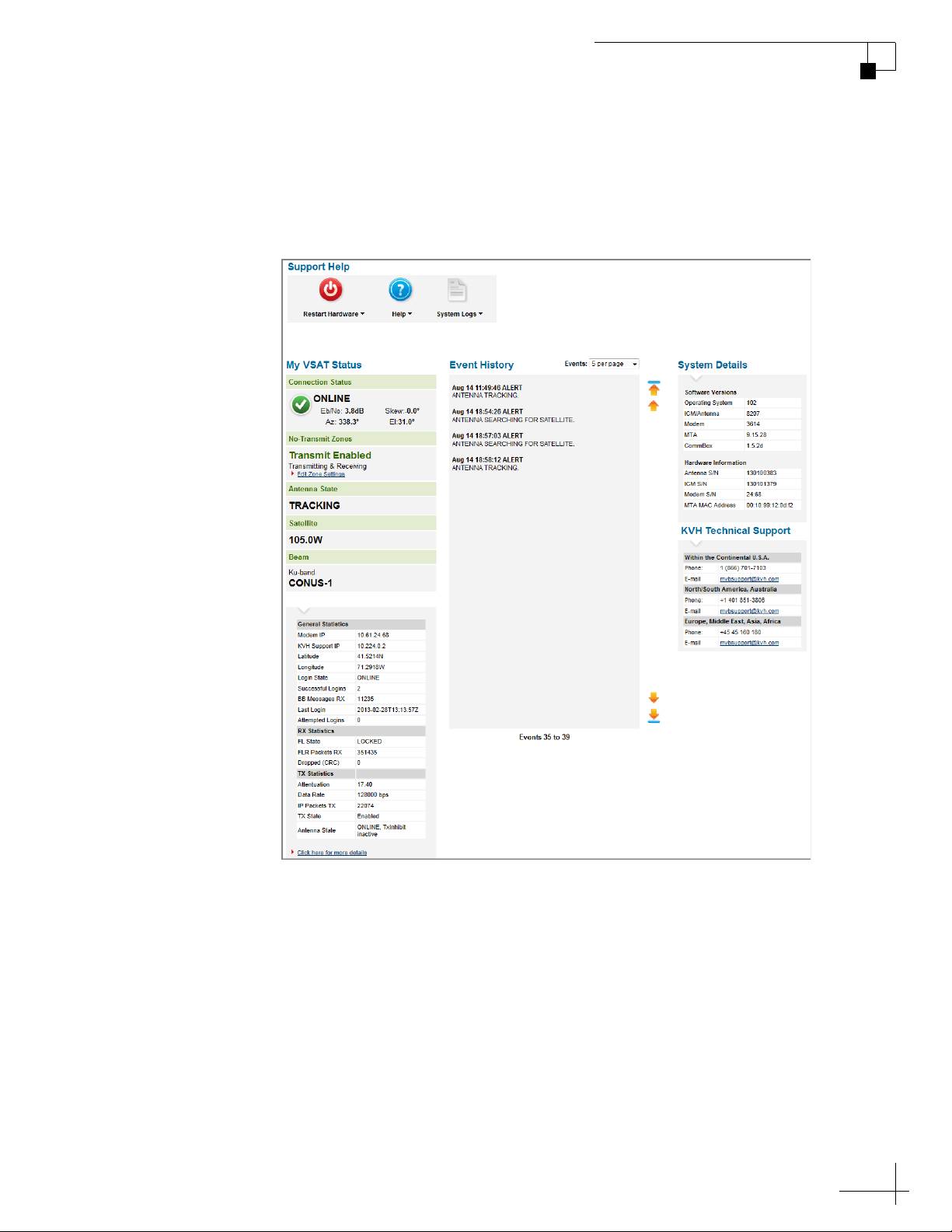
TracPhone V3-IP User’s Guide
Troubleshooting
Support Page of the Web Interface
The Support page provides more detailed system status information,
as reported by the ICM’s built-in modem.
Figure 8-3 Support Page
The “My VSAT Status” provides the same basic status information as
the Home page, with the addition of antenna pointing information:
Azimuth (Az), Elevation (El), and Skew. More detailed status
information is provided at the bottom of the page.
The tables below summarize the detailed status information that is
available on the Support page.
97
Page 96
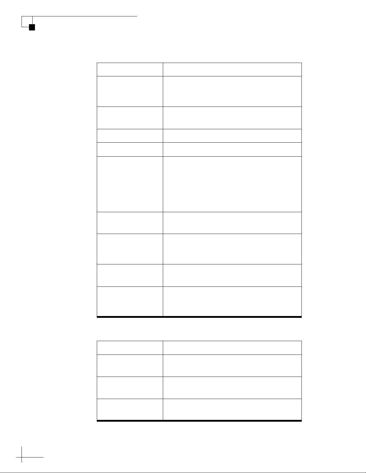
TracPhone V3-IP User’s Guide
Troubleshooting
General Statistics
Message Description
Modem IP The built-in modem’s external satellite IP
KVH Support IP This field does not apply to the TracPhone
Latitude Vessel latitude reported by the GPS
Longitude Vessel longitude reported by the GPS
Login State Status of the network login:
address: 10.61.xxx.xxx; its identity on the
mini-VSAT Broadband network
V3-IP
• Online – Logged into the network
• Offline – Logged out of the network; no
user traffic will pass
• Waiting – Attempting to log in; waiting for
hub reply
Successful Logins Number of times the built-in modem has
logged into the network since the last restart
BB Messages RX Number of bulletin board messages received
from the hub since the last restart; should
continuously increment while logged in
Last Login Date/time of the last successful login to the
network
Attempted Logins Number of times the built-in modem has
attempted to log into the network since the
last restart
RX Statistics
Message Description
FL State State of the forward link; should be
“Locked” while the modem is logged in
FLR Packets RX Number of data packets received; should
continuously increment while logged in
98
Dropped (CRC) Dropped data packets due to errors; should
not increment in large numbers
Page 97

TracPhone V3-IP User’s Guide
Troubleshooting
TX Statistics
Message Description
Attenuation Set by the hub; the lower the number, the
higher your antenna’s transmission power;
typically between 5-31 dB
Data Rate Rate at which the built-in modem is capable
of transmitting data; does not indicate the
actual data rate supported by your service
plan
IP Packets TX Number of data packets transmitted by the
modem
TX State Should be “Enabled” while tracking the
satellite, “Disabled” when pointing within a
configured no-transmit zone
Antenna State Status of the antenna:
• OFFLINE, TxInhibit active – Antenna is
not communicating with the ICM’s builtin modem
• SIGNAL ACQUISITION, TxInhibit active
– Antenna is searching for the satellite
• ONLINE, TxInhibit active – Antenna is
tracking the satellite, but inhibited from
transmitting due to either a no-transmit
zone or location in a restricted area
• ONLINE, TxInhibit inactive – Antenna is
tracking the satellite and allowed to
transmit
You can view additional information on the modem’s web page. Click
the Click here for more details link to access it.
99
Page 98
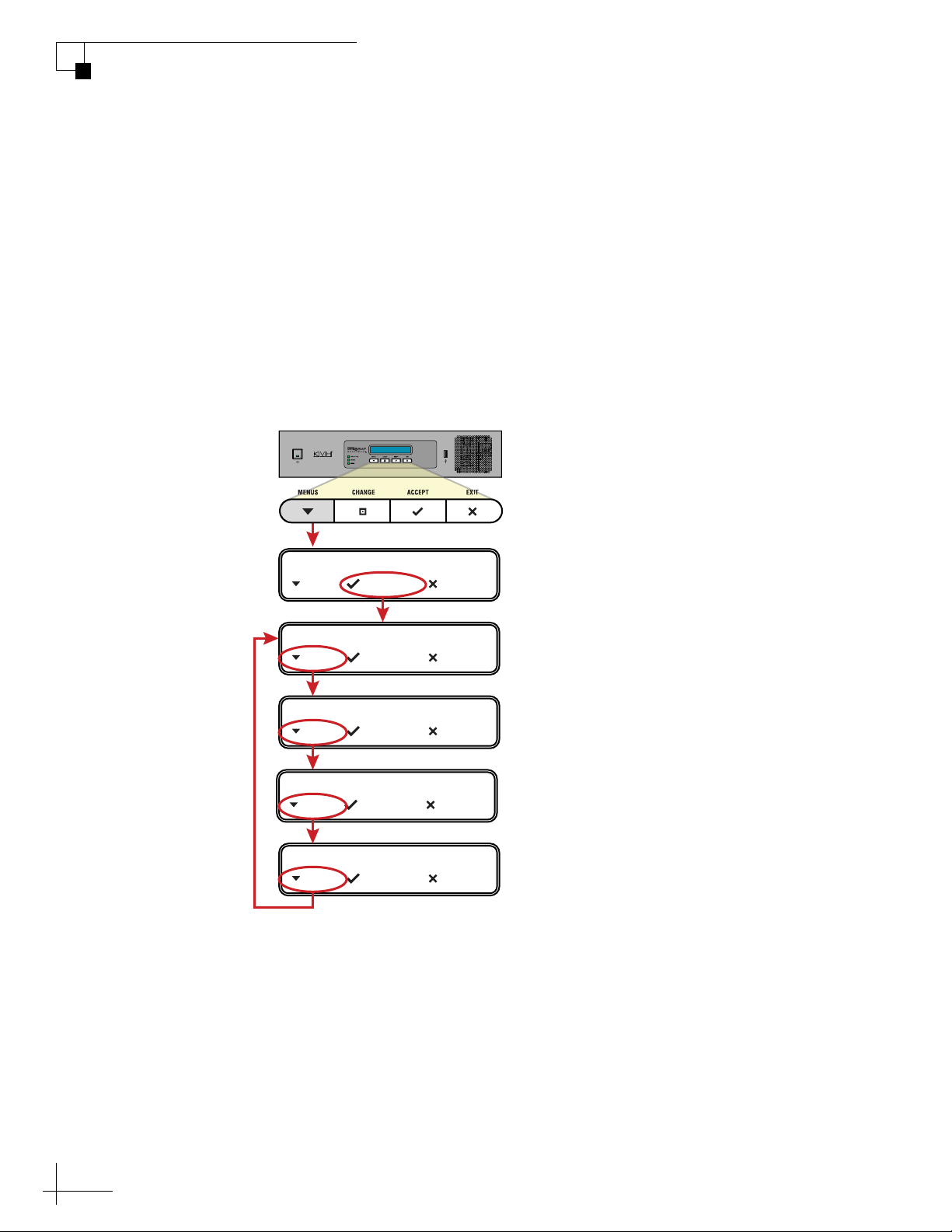
TracPhone V3-IP User’s Guide
Troubleshooting
Status Information on the ICM Front Panel LCD
On the front panel of the ICM, you can view much of the same status
information that’s available on the web interface.
To view the status information, follow these steps:
1. Press MENUS on the ICM’s front panel to bring up the Status
menu.
2. Press ACCEPT to access the status menu. Then use the
MENUS and ACCEPT buttons to scroll through the submenus.
Figure 8-4 Status Menu on ICM Front Panel
STATUS
NEXT SELECT EXIT
MODEM/NETWORK STATUS
NEXT SELECT EXIT
ANTENNA/ACU STATUS
NEXT SELECT EXIT
MTA/RSM(GPRS) STATUS
NEXT SELECT EXIT
GPS/HEADING STATUS
NEXT SELECT EXIT
Press ACCEPT to
view the status info
on each submenu.
100
Page 99

TracPhone V3-IP User’s Guide
Troubleshooting
Modem/Network Status
Message Description
MODEM SATELLITE IP External IP address of the ICM’s built-
in modem; identity of the modem on
the mini-VSAT Broadband network
(10.61.xxx.xxx)
MODEM STATE General status of the modem; “Online”
indicates the modem is connected to
the mini-VSAT Broadband service
LAN PORT STATUS Status of the Ethernet local area
network (LAN); “Link Up” indicates a
good connection
EB/NO Quality of the received signal;
Eb/No = Energy per bit/noise power
per Hertz
SATELLITE Satellite currently selected for mini-
VSAT Broadband service
BEAM Beam of the satellite currently selected
for mini-VSAT Broadband service
DOWNLINK FREQUENCY Frequency of the satellite downlink
SKEW TO SATELLITE Skew angle of the antenna’s LNB that
is required to receive signals from the
current satellite
101
Page 100

TracPhone V3-IP User’s Guide
Troubleshooting
Antenna/ACU Status
Message Description
ANTENNA STATE General status of the antenna; must be
ANTENNA DC INPUT DC voltage measured at the antenna’s
BUC POWER STATUS Status of the antenna’s BUC (transmit)
CURRENT AZ/EL Azimuth and elevation at which the
“Tracking” to connect to mini-VSAT
Broadband
circuit board; should be between
38 VDC and 44 VDC
power; should be between 22 VDC and
26 VDC
antenna is currently pointing; azimuth
is relative to the antenna’s “Forward”
arrow (bow)
CURRENT SKEW Current skew angle of the antenna’s
LNB
IPACU DC INPUT DC voltage measured at the ICM’s
power input; should be between
23 VDC and 25 VDC
IPACU ENET MODEM
PORT STATE
Status of the ICM’s Ethernet
connection to its built-in modem;
“Link” indicates the jumper cable is
connected between B1 and B2 on the
ICM’s rear panel
MTA/RSM(GPRS) Status
Message Description
MTA STATUS Status of the ICM’s built-in MTA;
“Registered” indicates the MTA is
connected to the voice service
RSM (GPRS) STATUS This message does not apply to the
TracPhone V3-IP
102
 Loading...