

DC/DC Converters
TEP 75WI Series, 75 Watt
Features
◆ Rugged, compact metal case
◆ Easy chassis mount
◆ Screw terminal adaptor available
for easy connection
◆ Ultra wide 4:1 input voltage range
◆Full load operation up to 60°C with
convection cooling
◆ Soft start
◆ Reverse input voltage protection
◆ Input protection filter
◆ 3-year product warranty
pending
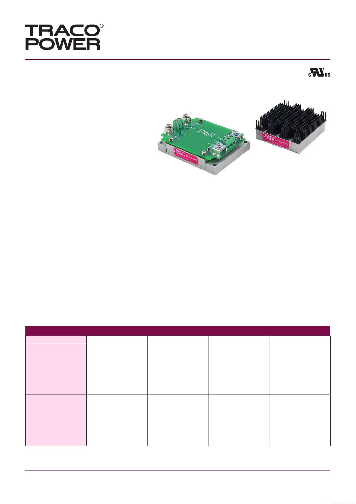
(Models pictured with chassis mount adaptor and optional heatsink)
The TEP-75WI Series is a family of isolated high performance dc-dc converter
modules with ultra-wide 4:1 input voltage ranges which come in a rugged, sealed
metal case.
These converters are suitable for a wide range of applications, but the product is
designed particularly also for industrial applications where often no PCB mounting
is possible but the module has to be mounted on a chassis. Four threaded M3 inserts
in the module makes chassis mount or attachment of a heatsink for optimal thermal
management very simple.
For easy connection there is also an unique adaptor available with screw terminals.
A very high efficiency allows an operating temperature up to +60°C with natural
convection cooling without power derating. Further features include output voltage
trimming, Remote On/Off and under voltage lockout. The very wide input voltage
range and reverse input voltage protection make these converters also an interesting
solution for battery operated systems.
Models
Order code* Input voltage Output voltage Output current max. Efficiency typ.
TEP 75-2411WI
TEP 75-2412WI
TEP 75-2413WI 9 – 36 VDC
TEP 75-2415WI
TEP 75-2416WI
TEP 75-2418WI
TEP 75-4811WI
TEP 75-4812WI
TEP 75-4813WI 18 – 75 VDC
TEP 75-4815WI
TEP 75-4816WI
TEP 75-4818WI
(24 VDC nominal)
(48 VDC nominal)
* – add suffix –CM, –CMF for models with chassis mount adaptor, see last page.
– add suffix –N for negative remote control, see page 3 -> Remote On/Off
http://www.tracopower.com Page 1 of 6
5.0 VDC 15.0 A 88 %
12 VDC 6.3 A 88 %
15 VDC 5.0 A 88 %
24 VDC 3.2 A 87 %
28 VDC 2.7 A 87 %
48 VDC 1.6 A 87 %
5.0 VDC 15 A 90 %
12 VDC 6.3 A 89 %
15 VDC 5.0 A 89 %
24 VDC 3.2 A 87 %
28 VDC 2.7 A 87 %
48 VDC 1.6 A 87 %

DC/DC Converters
TEP 75WI Series 75 Watt
Input Specifications
Input current at no load 24 Vin; 5 – 15 VDC models: 185 mA typ.
24 Vin; 24 – 48 VDC models: 85 mA typ.
48 Vin; 5 – 15 VDC models: 90 mA typ.
48 Vin; 24 – 48 VDC models: 50 mA typ.
Input current at full load 24 Vin models: 3600 mA typ. (see Note 1)
48 Vin models: 1800 mA typ.
Start-up voltage / under voltage shut down 24 Vin models: 8.5 VDC / 7.5 VDC typ.
48 Vin models: 17.5 VDC / 16 VDC typ.
Surge voltage (100 msec. max.) 24 Vin models: 50 V max.
48 Vin models: 100 V max.
Conducted noise EN 55022 level A, FCC part 15, level A
(chassis mount option –CFM required)
ESD (electrostatic discharge) EN 61000-4-2, air ±8 kV, contact ±6 kV,
perf. criteria A
Radiated immunity EN 61000-4-3, 10 V/m, perf. criteria A
Fast transient / Surge EN 61000-4-4, ±2 kV, perf. criteria A
EN 61000-4-5, ±1 kV perf. criteria A
With external input capacitor e.g. Nippon
chemi-con KY 200 µF, 100 V, ESR 48 mOhm
or with chassis mount option –CFM
Conducted immunity EN 61000-4-6, 10 Vrms, perf. criteria A
Reverse voltage protection parallel diode
Recommended input fuse (slow blow) 24 Vin models: 10 A
48 Vin models: 5 A
Output Specifications
Voltage set accuracy ±1 %
Output voltage adjustment +10 % / –20 % by external resistor
see application note:
www.tracopower.com/products/tep75wi-application.pdf
Regulation – Input variation Vin min. to Vin max. 0.2 % max.
– Load variation (0 – 100 %) 5 – 15 VDC models: 0.3 % max.
24 – 48 VDC models: 0.3 % max.
Temperature coefficient ±0.02 %/K
Minimum load not required
Remote sense 10 % max. of Vout nom.
(tim up value to subtract)
Ripple and noise (20 MHz Bandwidth) 5 VDC models: 75 mVpk-pk max.
12 & 15 VDC models: 100 mVpk-pk max.
24 & 28 VDC models: 200 mVpk-pk max.
48 VDC models: 300 mVpk-pk max.
Start up time (nominal Vin and constant resistive load) 25 ms typ. (at power On or remote On)
Transient response (25 % load step change) 200 µs typ.
Output current limitation at 110 -140 % of Iout max.
Over voltage protection at 115 -130 % of Vout nom.
Short circuit protection indefinite, automatic recovery.
Note 1: For operation at low input voltage an input capacitor 4.7µF/50V X7R MLCC or 68µF/100V, 110mOhm Nippon chemi-con
KY series is recommended for a reliable supply of the pulse current. Capacitor is already include with chassis mount option –CM and
–CFM
http://www.tracopower.com Page 2 of 6

DC/DC Converters
TEP 75WI Series 75 Watt
Output Specifications
Capacitive load 5 VDC models: 30‘000 µF max.
12 VDC models: 5‘250 µF max.
15 VDC models: 3‘330 µF max.
24 VDC models: 1‘330 µF max.
28 VDC models: 960 µF max.
48 VDC models: 330 µF max.
General Specifications
Temperature ranges – Operating –40°C to +75°C
– Case temperature +105°C max.
– Storage –55°C to +125°C
Thermal impedance – without Heatsink 6.7 °C/W
– with Heatsink 4.7 °C/W
Derating see derating graps page 4
Over temperature protection at 115°C
Thermal shock acc. MIL-STD-810F
Humidity (non condensing) 95 % rel H max.
Reliability, calculated MTBF (MIL-HDBK-217F, @ 25°C, ground benign) 75‘000 h
Isolation voltage (60sec.) – Input/Output 2’250 VDC (basic insulation)
– Input/Case 1’500 VDC
Isolation capacity – Input/Output 2500 pF max.
Isolation resistance – Input/Output (500 VDC) >1 GOhm min.
Switching frequency 300 kHz typ. (puls width modulation)
Safety standards UL 60950-1 , IEC 60950-1, EN 60950-1
Safety approvals (pending) UL 60950-1, CB- test report
Remote On/Off – positive logic (standard) – On: 3 to 12 VDC or open circuit
– Off: 0 to 1.2 VDC
– negative logic (option -N) – On: 0 to 1.2 VDC
– Off: 3 to 12 VDC or open circuit
– Off idle current: 3 mA
Environmental compliance – Reach www.tracopower.com/products/tep75wi-reach.pdf
– RoHS RoHS directive 2002/95/EC
Application notes www.tracopower.com/products/tep75wi-application.pdf
or short circuit pin 1 and 3
or short circuit pin 1 and 3
All specifications valid at nominal input voltage, full load and +25°C after warm-up time unless otherwise stated.
http://www.tracopower.com Page 3 of 6

Output Power Derating
Models with heatsink Models without heatsink
DC/DC Converters
TEP 75WI Series 75 Watt
24 Vin models: Output 5–15 VDC
24 Vin models: Output 24–48 VDC
48 Vin models: Output 5–15 VDC
24 Vin models: Output 5–15 VDC
24 Vin models: Output 24–48 VDC
48 Vin models: Output 5–15 VDC
48 Vin models: Output 24–48 VDC
http://www.tracopower.com Page 4 of 6
48 Vin models: Output 24–48 VDC

0.20 0.5
0.023
2.40
2.00
0.30
0.70
1.00
1.900.19
2.28
(57.9)
1
2
3
4
5
6
8
9
7
4 x M3 THD
(48.26)(4.8)
(50.80)
(61.0)
(17.78)
(12.7)
(25.40)
Bottom view
(7.62)
(0.6)
(5.1)
(trough hole)
DC/DC Converters
Top view
0.95
0.45
(24.2)
(11.4)
2.40 (61.0)
2.28 (57.9)
TEP 75WI Series 75 Watt
General Specifications
Casing material metal
Potting material silicon (UL94V-0 rated)
Base material FR4
Vibration acc. MIL-STD-810F
Dimensions
TEP 75 module
Weight: 97g (3.42 oz)
Pin diameter pin 5 & 9: 0.08 (2.0)
Pin diameter other pins: 0.04 (1.0)
TEP-HS1 Heatsink (pictured with heatsink mounted)
*Sense line to be connected
to the output either at the
module or at the load under
regard of polarity.
Pin
Pin-Out
1
2
3
4
5
6
7
8
9
– Vin
Case
Remote On/Off
+ Vin
– Vout
– Sense*
Trim
+ Sense*
+ Vout
Order code: TEP-HS1
Includes heatsink with termal pad and mounting screws
To order modules with mounted heatsink ask factory.
Weight: 135g (4.76 oz)
(Heatsink + Converter)
Dimensions in Inch, () = mm
Tolerances ±0.02 (0.5)
Pin pich tolerances ±0.01 (0.25)
Mounting hole pich tolerances ±0.01 (0.25)
http://www.tracopower.com Page 5 of 6

J
enatschstrasse 1 · CH-8002 Zurich · Switzerland
Tel. +41 43 311 45 11 · Fax +41 43 311 45 45 · info@traco.ch · www.tracopower.com
DC/DC Converters
1.10
0.68
(28.0)
(17.3)
1.18
0.68
(30.0)
(17.3)
1.31 (33.3)
3.35
3.071
(85.0)
(78.0)
2.40
2.126
(61.0)
(54.0)
0.14
(3.5)
(3.5)
4 x Ø0.17 (4.3)
1.90
(48.3)
1.02 (25.9)
TEP 75WI Series 75 Watt
Chassis Mount Adaptor
TEP 75 module with chassis mount adabtor (suffix –CM or –CMF)
For easy chassis mounting the converter modules can be supplied with an adaptor option consisting of a screw terminal connection
board (soldered to converter pins)and a chassis mount adaptor.
In addition this Chassis mount option is available with an EMI-filter(see EMI specification)
Suffix –CM: Chassis mount adaptor
Suffix –CMF: Chassis mount adaptor with EMI filter
Please note that adaptors cannot be ordered as seperate
items but are factory assembled.
Connection
Pin
– Vin
Case
Remote On/Off
+ Vin
– Vout
– Sense*
Trim
+ Sense*
+ Vout
*Sense line to be connected
to the output either at the
module or at the load under
regard of polarity.
1
2
3
4
5
6
7
8
9
Specifications can be changed any time without notice.
Dimensions in Inch, () = mm
Tolerances ±0.02 (±0.5)
Mounting hole pich tolerances ±0.01 (±0.25)
Rev. 08/09
Page 6 of 6
 Loading...