

Page 1
Digitally signed by Michael
Hulin
Date: 2018.03.02 10:39:47 Z
Digitally signed by David Hulin
DN: cn=David Hulin, o=Lifelines Ltd,
ou=Development, [email protected],
c=GB
Date: 2018.03.02 11:05:11 Z
Digitally signed by Michael
Hulin
Date: 2018.03.02 11:58:46 Z
Trackit Mk3
User Manual
Part no. 1114
Issue 2.4
28 February 2018
Created Checked Approved
Page 2

Trackit Mk3 User Manual
Version History
V2.4 (February 2018)
• Added disinfec tion information in sec tion 2.7.
• Changed N.B. to 0086 (BSI).
V2.3 (May 2014)
• Latest 4
• Bluetooth recording times a nd range details added
• Latest version low-power XPOD Pulse Oximeter details added in Appendix 2
V2.2 (September 2011)
• Trackit Mk3 in tr oduced: USB Interface detail added to Sections 1.2, 1.3, 3.1, 3.2 and 4.2.
• Large memory cards (FAT32) a dded in Section 5.6.
• Aux Box 2 added in Appendix 2.
• More Setup parameters added to Appendix 5.
• Quick Setup Guide adjuste d in Appendix 6.
• Troubleshooting adjusted i n Appendix 8.
V2.1 (June 2010)
• Added Bluetooth indicator to Figure 6
• Added ‘Internal Bluetooth’ pa r a gr a ph to Appendix 5
• Minor amendments to section 5.7 ‘Reading an ambulatory recording’
• Minor amendmen ts to Appendix 4 ‘Network Connection’
V2.0 (April 2010)
• Reformatted to A4 page s ize
• Added full documentation to Appendix 4:
• Added full documentation to Appendix 5: Bluetooth Wireless
• Appendix 7: Troubleshooting guide moved to Appendix 8
• Appendix 8: Manufa c turer’s Declaration m oved to Appendix 9
• Added Appendix 7: Trackit Setup Wizard
V1.8 (28 January 2010)
• Virus protection recommendations added, Page 5.
• Lifelines logo adjusted, P a ge 3.
• References to Windows 98 a nd ME removed, Sections 1.4 and 4.
• Check with distributor for later software version added, Section 4.
• Picture of latest main Tool ba r updated, Figure 16, and table below u pda ted.
• Picture of main ongoing dis pla y window updated, Figure 23.
• Appendix 3 added, Photic and Hyperventilation. Photic refers to separate documentation. Old
• Appendix 4 added, Trackit Plus and Plus with Video Software. B oth r efer to separate docu-
• Appendix 5 added, Bluetoo th Wireless. Refer to separate docu m entation. Old Appendix 5 now
th
Generation internal Bluetooth d etails added in A ppendix 5
o Section 1 Record to PC
o Section 2 Network Connection
o Section 3 Video
Appendix 3 now Appendix 4.
mentation. Old Appendix 4 now Appendix 5.
Appendix 6.
2
Page 3

Trackit manufactured by:
Lifelines Ltd, 7 C larendon Court,
Over Wallop, near Stockbridge,
Hampshire SO20 8HU, UK
Telephone +44 (0)1264 782226
www.LLines.com
[email protected]
Trackit Mk3 User Manual
0086
3
Page 4

Trackit Mk3 User Manual
Disclaimers & Warranties
The information in this section is sub je c t to change without n otice.
Except as stated below, Lifelines Ltd m a kes no warranty of an y kind with regard to this material,
including, but not limited to, the implied warranties of merchantability and fitness for a p a r ticular
purpose. Lifelines shall not be liable for errors contained herein or for inc id ental or consequentia l
damages in conn e c tion with the furn ishing, performanc e or use of this material.
Lifelines shall w a r rant its products a g a inst all defects in m a terial and workman sh ip for one year
from the date of delivery.
Misuse, accident, modification, unsuitable physica l or operating envir onment, improper main tenance or damage caused by a product for which Lifelines is not responsible will void the warranty.
Lifelines do not w a rrant uninterrupted or error-free oper ation of its products .
Lifelines or its authorised agents will repair or replace any products that pr ove to be defective dur-
ing the warranty period, provided that these products are used as prescribed in the operating instructions in the user’s and service manuals.
No other party is authorised to make any warranty to assu m e lia bility for Lifelines products. Lifelines will not recog nise any other wa r r a nty, either implied or in writing. In ad dition, services performed by someone other than Lifelin e s or its authorised agents or any technic al mod ification or
changes of products without Lifelin es prior, written consent may be cause for voiding this warr anty.
Defective products or par ts must be return ed to Lifelines or its auth orised agents, alon g with an
explanation of th e failure. Shipping c os ts must be prepaid.
Lifelines Ltd. manuf a c tures hardware and software to be used on or w ith standard PC-compatible
computers and operating s oftware. Lifelines, however, assumes no responsibilit y for the use or reliability of its software or hardware with equipment that is not furnished by th ir d-party manufacturers accepted by Lifelines at th e da te of purchase.
All warranties for third-party products used within the T rackit system are the responsibility of the
relevant manufacturer. Please refer to the relevant d ocumentation on each product for further details.
This document c ontains proprietary information that is protected by copyright. All rights are reserved. No part of this document may be p hotocopied, reproduced in any other form or translated
into another language without the prior written consent of Lifelines.
Trademarks
Microsoft, Windows and Windows N T are registered tradema r ks of the Microsoft Corporation. All
other trademarks and prod uct names are the property of their relevant owners.
Responsibility of manufacturer
The manufacturer and distributor con sider themselves responsible for the equipment’s sa fety, reliability and performanc e only if:
any peripheral equipment to be used with Trackit is supplied by third-party providers recom-
mended by the manufacturer;
assembly operations, extension s , readjustments, m odifications, or repa irs are carried out by
persons authorised by the manufacturer;
the electrical ins tallation of the rele vant room complies with the appropriate requirements;
the equipment is used by a hea lth-care professional and in accordance with the instruc tions for
use.
Note: the manufacturer has a policy of continual product imp r ovement; hence the equipment
specifications a re subject to change without notice.
Check with Lifelines or your distributor if a software upda te is available.
4
Page 5

Trackit Mk3 User Manual
Note: Medical electrical equipment needs s pec ia l precautions regarding E M C and needs to be installed and put into service according to the EMC informa tion provided in the Ap pe ndix.
Software and V irus Protection
Lifelines takes all reasonable steps to ensure that it’s software is virus-free. In line with modern
computing practice, it is advisable that con tinual protection a g a inst viruses, trojans, malware, adware etc. is provid ed on the PC used for installation and the surrounding systems. Please note the
following recommendations which should be su pported by your internal IT/Computing department
procedures and practices:
1. Virus protection softw a r e s hould be installed on e very computer at risk of infection. This soft-
ware should have a resident ( on line) shield and provide email sca nning if appropriate.
2. Virus scanning should be s et to m anual mode or auto m a tic if desired but at a time when the
system is not being used.
3. All programs offering au to-update features, inclu ding Windows, should be set to manual or
automatic if desired but at a time when the system is not bein g used.
4. Adopt f ormal departmental or organisational procedures to en sure the integrity a nd safe op-
eration of the me dic al equipment and supporting systems.
5
Page 6

Trackit Mk3 User Manual
Contents
Version History 2
Disclaimers & Warranties 4
Trademarks 4
Responsibility of manufacturer 4
Software and V irus Protection 5
Contents 6
Illustrations 8
1 System Overview 10
1.1 General descrip tion 10
1.2 Cautions and Warnings 10
1.3 Explanation of s ymbols 11
1.4 The system and its parts 12
1.5 Specifications and safety 12
Description of th e c om p onents 13
2 Installation an d Maintenance 15
2.1 Checks for completeness and integrity 15
2.2 Environmental parameters for ope r a tion 15
2.3 Use in the home environment 15
2.4 Power supply connections 15
2.5 Use with other equipment 16
2.6 Interference 16
2.7 Maintenance and cleaning 16
2.8 Disposal of equipment 16
3 Connections f or Trackit Mk3 setup 17
3.1 Overview 17
3.2 Connecting the Trackit Mk3 18
3.3 Switching on 18
3.4 Warning symb ols on the display 19
4 The setup software 20
4.1 Setting up a recording protoc ol 20
4.2 Configuring the recorder 25
4.3 Montage Editor 31
5 The ambulatory recording 33
5.1 Changing batteries and ca r ds 33
5.2 Fitting the Click on PCU 37
5.3 Event marking 38
5.4 Ending a recording 38
5.5 Identifying a recording 39
5.6 Advanced Settings 39
5.7 Reading an ambulatory rec ording 43
Appendix 1: Trackit Mk3 Specifications 44
EEG inputs 44
Polygraphy in puts 44
Aux. high-level DC Inputs 45
Modes of operation 45
Connections, p or ts and controls 45
Back-light display 45
Recording format 45
Physical characteristics 45
Safety and EMC standards 46
6
Page 7

Trackit Mk3 User Manual
Appendix 2: Trackit Mk3 options 47
Nonin XPOD pulse oximeter 47
Appendix 3: Photic Stimulator and Hyperventilation 50
Photic Stimulation 50
Hyperventilation 51
Appendix 4: Record to PC and S yn c hronised Video 53
1 Record to PC 53
2 Network Conne c tion 53
3 Video 57
Appendix 5: Bluetooth Wireles s 61
Introduction 61
System overview 62
Connection and use 63
Application PC Setup 66
Trackit and Bluetooth Module Setu p 69
Trackit Bluetooth Module Specifications 78
Parameter Data 78
Regulatory 79
FCC Statement 80
IC Compliance 80
Guidelines for E fficient and Saf e Use 81
Trackit Bluetooth Battery Power Con sumption 83
Bluetooth Ran g e 83
Bluetooth Knowledge Base 85
Appendix 6: Trackit quick setup and operation guide 86
Appendix 7: Trackit Setup W iz a r d 87
Appendix 8: Troubleshooting guide 88
COM port problems with Bluetooth com m unication to Trac kit Mk3 88
Problems startin g the recording 88
File review problems 89
Appendix 9: Manufacturer’s Declaration 90
EMC Compatibility 90
7
Page 8

Trackit Mk3 User Manual
Illustrations
Figure 1 Connecting the Trackit Mk3 for recorder set-up 17
Figure 2 Connec ting to the Trackit M k3 recorder 18
Figure 3 Trackit Mk3 recorder : front panel 19
Figure 4 The Trackit Mk3 display 19
Figure 5 New Patient dialog 20
Figure 6 New Patient databa s e 21
Figure 7 Signal list 21
Figure 8 Signal editing tool 22
Figure 9 EEG setup 22
Figure 10 Setup Recording dialog 23
Figure 11 View Hookup 23
Figure 12 Channel setu p 24
Figure 13 Recording Cha nnel editing 25
Figure 14 Track it s oftware toolbar 25
Figure 15 Trackit Control Panel 26
Figure 16 Trackit status 'B' 27
Figure 17 Recording Control 27
Figure 18 Ongoing trace display 29
Figure 19 Adjust display pa r a meter s 30
Figure 20 Impedance chec k 30
Figure 21 The online event viewer 31
Figure 22 Montage Editor 32
Figure 23 Opening the rear battery box/door 33
Figure 24 Removing and replac ing PP3 batteries 34
Figure 25 Removing and replacing Lithium rechargeable batter y 34
Figure 26 Closing the rear Battery box/door 35
Figure 27 Removing and replacing the flash card 36
Figure 28 Removing the flash card 36
Figure 29 Clickon PCU Retaining scre w location 37
Figure 30 Detach the PCU 37
Figure 31 Lift the PCU away from the Trackit Mk3 38
Figure 32 Locating the PCU 38
Figure 33 Trackit Defaults Tab 1 40
Figure 34 Trackit Defaults | Tab 2 41
Figure 35 Pulse oximeter an d oximeter probe 47
Figure 36 Connec ting the oximeter to Trackit Mk3 48
Figure 37 Connecting the oximeter to the oximeter probe 48
Figure 38 Attaching the oximeter probe to the finger 48
Figure 39 Display of SaO2 49
Figure 40 Photic Stim ulation 50
Figure 41 Photic Stim ulation control window 50
Figure 42 Photic trigger signal definition 51
Figure 43 Hyperventilation 51
Figure 44 Hyperven tila tion control win dow 52
Figure 45 Trackit video prev iew 59
Figure 46 Track it M k3 with Internal Blu etooth Module 62
Figure 47 The Trackit Control Panel 63
Figure 48 A typical Bluetooth Place s view 64
Figure 49 Trackit Main Sc reen 65
Figure 50 Options Tab 1 66
Figure 51 Options Tab 2 67
Figure 52 Trackit Defaults Tab1 69
Figure 53 Trackit Defaults Tab2 70
Figure 54 Trackit Defaults Tab 3 70
Figure 55 Trackit Defaults Tab 4 72
8
Page 9

Trackit Mk3 User Manual
Figure 56 Trackit Defaults | Bluetooth Setup Tab 1 (General) 73
Figure 57 Trackit Def a ults | Bluetooth Setu p Tab 2 (Profile) 74
Figure 58 Track it De faults | Bluetooth S e tup Tab 3 (Serial) 75
Figure 59 Track it De faults | Bluetooth S e tup Tab 4 (Version) 76
Figure 60 Track it De faults | Bluetooth S e tup Tab 5 (Misc) 76
Figure 61 Trackit Def a ults | Bluetooth Setu p Tab 6 (Pairing) 77
9
Page 10

Trackit Mk3 User Manual
1 System Overview
1.1 General description
Intended use
The Trackit Mk3 is intended to measure and record EEG signals.
Indications for use
The Trackit Mk3 is used as an aid in the diagnosis of neurophysiological disorders such a s epilepsy.
General description
The Trackit Mk3 is a multi-channel, ambulator y, electroencepha lograph recorder. It is a compact
body-worn device that is battery powered and the data is stored on a Compact Flash card.
The device is suita ble for use in a clinica l environment and in a n outpatient setting. The EEG
electrodes are fitted to the patient by a trained clinician prior to the patient being sent home. No
subsequent intervention is required by the patient.
Upon completion of the rec or d ing, the data which is stored on a Compact Flash card is reviewed b y
a clinician using review and analysis software on a PC.
This device is intended only as an adjunct device in patient assess m ent; it must be used in
conjunction w ith other methods of patient diagnosis.
The device does not s ustain or suppor t life.
Intended User
The intended user of the device is a healthcare professional who h a s the training and knowledge to
undertake EE G examinations and is familiar with EEG equipm ent and practice.
1.2 Cautions and Warnings
CONTRAINDICATIONS: Do not use the Trackit Mk3 in an MRI envir onment, in an exp los ive
atmosphere or during defibrillation.
WARNING: This devic e is intended to be used by a healthcar e professional and in accordance with
these instructions for u s e w hich must be read in their entirety before the device is used.
WARNING: This devic e in intended only as an adjunct dev ic e in pa tient assessment; it must be
used in conjunc tion with other methods of patient diagnos is.
WARNING: Lifelines does not supply EEG electrodes. The unit accepts standard 1.5 mm
touchproof electrodes u s in g D IN 42802-style connect ors. To ensure patient safety, the electr odes
used must be approved to the Medic a l Device Directive 93/42/EEC in Europe or to the relevant
local standards outside Europe.
CAUTION: The conduc tive part of electrodes and their connectors , including the Neutral electrode,
should not contact other conductive parts including earth.
WARNING: Lifel ines does not supply the Nonin sensor. Only use the ‘PureLight’ sensor s s pec if ied
by Nonin to be used with their Oximeters.
WARNING: Strangulation hazard due to long cables. A s with all medical equipme nt, carefully
route patient cabling to reduce the possib ility of patient entanglement or strangulation.
CAUTION: When in close proxim ity to the recorder, do not use mobile phones, transmitters, p ower
transformers, motors, or other equipment that gener a tes magnetic fields. Refer to the Appendix for
more information. Medical electrical equipment needs special precaution s r ega r ding EMC and needs
to be installed and put into service according to the EMC in formation provided in the Appendix.
WARNING: The f unction or safety of the equipment could be impaired if it has been subjected to
unfavourable c onditions in storage or in transit. If at any tim e function or safety is thought to be
impaired, the instrumen t s hould be taken out of operation and secured against unintended us e.
WARNING: Do not open the equ ipment.
WARNING: Do not modify this equipmen t without the authorization of the manufacturer.
10
Page 11
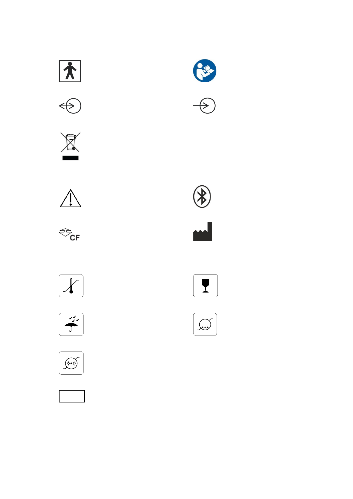
1.3 Explanation of symbols
-10
+50
°C
10
95
%RH
500
1060
hPa
IP22
Type BF equipment Follow operatin g instructions
Input/output connection Input connection
Special recycling required, do not dispose of in la ndfill. When this eq uipment has
reached the end of its useful life, it mu s t b e disposed of in an en vironmentallyfriendly way. Waste electrical and electronic equipment (WEEE) requires special
procedures for recycling or disposal. This includes batteries, printed circuit boards,
electronic comp onents, wiring and other elements of electronic devices. Follow all
of your respective local laws and r eg ulations for the proper d is p os al of such
equipment. Contact your local distributor for information concerning this.
Trackit Mk3 User Manual
Consult warnings in User Manual Bluetooth
Push to eject Compact Flash card Manufacturer
Storage and transport symbols
Temperature limits Fragile
Keep dry Relative humidity limi ts
Barometric pressure limits
International p r otection code
Protected against ingress of solid object 12.5 mm diameter.
Protected against access to hazardous parts with finger.
Protected against ingress of water dripping (15° tilted).
11
Page 12

Trackit Mk3 User Manual
EN60601-2-26
quirements and EEG systems.
ments.
quirements.
ments, calling:
EN55011
Conducted Emissions, Group 1, Class B
EN55011
Radiated Emissions, Group 1, Class B
EN61000-4-2
Electrostatic D ischarges
1.4 The system and its parts
The Trackit Mk3 recorder is a multi-channel1 ambulatory ele c troencephalograph designed for use in
a variety of mon itor ing applications, including those concerned with neurological and sleep disorders.
1
Note
: Trackit Mk3 is available in a number of versions, including a 32-channel (Trackit-32/0 or
Trackit-24/8), a 24-channel (Trackit 24/0) and a 12-channel (Trackit-24/0). The version is displayed on the Trackit Mk3 LCD at switch-on. This manual applies to all versions, the only difference
being the number of channels.
The Trackit Mk3 recorder comprises the follow ing components:
Recorder
Trackit-32/0 (32 EEG) part number 1186
Trackit-24/0 (24 EEG) part number 1187
Trackit-12/0 (12 EEG) part number 1189
Trackit-20/4 (20 EEG, 4 POLYGRAPHIC) part number 1184
Trackit-18/8 (18 EEG, 8 POLYGRAPHIC) part number 1185
Trackit-24/8 (24 EEG, 8 POLYGRAPHIC) part number 1188
Recorder with inter nally fitted wirel e s s Bluetooth option
Trackit-32/0 (32 EEG) part number 1171
Trackit-24/0 (24 EEG) part number 1172
Trackit-12/0 (12 EEG) part number 1174
Trackit-20/4 (20 EEG, 4 POLYGRAPHIC) part number 1169
Trackit-18/8 (18 EEG, 8 POLYGRAPHIC) part number 1170
Trackit-24/8 (24 EEG, 8 POLYGRAPHIC) part number 1173
Patient connection unit (PCU) Clic kon
PCU-clickon Short part number 1181
Patient connection unit (PCU) Cabled
PCU-cabled 24/0 part number 1104
PCU-cabled-Extended 32/0 (univer s a l) part number 1136
Cable, PCU 32ch 1m part number 1106
Cable, PCU 32ch 0.5m part nu m ber 1105
Cable, USB 3m part number 1277
Trackit Mk3 strap, adult part number 1117
Trackit Mk3 strap, child part number 1118
Trackit Mk3 bag with PCU-clickon part number 1259
Trackit Mk3 set up software part number 1009
Trackit Mk3 User Manual part number 1114
Battery Box PP3 part number 1111
Battery Box PP3-Small part number 1140
Battery Box Li part number 1112
1.5 Specifications and safety
Refer to Appendix 1 for specifica tions.
The system has been certified and complies with the following s ta ndards:
EN60601-1 and
European standard for medical electrical equipment, general re-
UL60601-1:2003 USA standard for medical electrical equipment, gener a l require-
CAN/CSA 22.2 No 601.1 M90 Canadian standard for medical electrical equipment, general re-
EN60601-1-2:2001 European standard for medical electrical equipment, EMC require-
12
Page 13

EN61000-4-3
Immunity - Radiated RF Field
EN61000-4-4
Immunity - Transients Bursts
EN61000-4-5
Immunity – Surges
EN61000-4-6
Immunity – Conducted
EN61000-4-8
Immunity – Power frequency fields
EN61000-4-11
Immunity – Voltage dips, interruptions
EN61000-3-2
Harmonic Emissions
EN61000-3-3
Voltage Fluctuations/flicker
or USB powered (Mk3)
Degree of protection against harmful ingress
Ordinary (no protection)
Mode of operation
Continuous
Degree of safety of application in the presence of a
or nitrous oxide
Not suitable
Degree of protec tion against electr ic al shock (when connected to host system )
Trackit Mk3 User Manual
Type BF
Type of protection against electrical s hock (when connected to host system )
of water
flammable anaes thetic mixture with air or with oxygen
Internally powered
or Mains powered Class 1 or 2 (Mk2)
Description of the components
The Trackit Mk3 recorder
The Trackit Mk3 is a multi-channel recording device designed for use in recording a patient’s E EG
signals. It comprises a 24-channel EEG (monopolar) amplifier acquisition board, an 8-channel polygraphic acquisition board and contr ol b oa r d with all the I/O inter face for serial an d patient communication. When connected to a host PC , the device has built-in is olation for patie nt safety. The device may be powered either by its ow n batteries or a PC USB port. EEG data is stored on an internal CF card. The data format is native European Data Format (EDF) , allowing the EEG files to be
reviewed by any EDF-compatible EEG reader.
Patient Connection Unit
The Patient Con nection Unit (PCU) connects the stan dard 1.5mm touchproof EEG recording electrodes attached to the patient to the Trackit Mk3 unit. It is available either as a ‘Cabled’ type which
is connected via a screened cable or a ‘C lickon’ type which fits on the Trackit Mk3 directly without
needing a cable.
WARNING: Lifelines does not supply EEG electrodes. T he PCU accepts st a nda rd 1.5 mm
touchproof elec t r odes using DIN 42802-style connectors. To ensure pati ent safety, the
electrodes used must be approved to the Medical Device Directive 93/42/EEC in Europe
or to the relevant l oca l standards outside Europe.
CAUTION: The conductive part of el ectrodes and their connectors, incl uding the Neutral
electrode, shoul d not contact other c onductive parts including earth.
PC Connection Cable
The Trackit Mk3 plugs directly into a USB port on the PC.
Batteries
3 PP3 disposable alkaline ba tteries are optionally supplied with the Trackit Mk3 recorder. Alternatively, a recha r g ea b le L ithium battery option is available and a small (single) PP3 opt ion.
CF flash card
A Compact Flash (‘CF’) card is used to store the EEG data recorded by Trackit Mk3. Storage cards
of varying capacity are available in the CF format.
13
Page 14

Trackit Mk3 User Manual
Trackit setup software
The Trackit setup software runs under Microsoft Windows 2000 (with SP2), Windows XP, Windows
Vista or Windows 7 on the host PC and is used to setup and review the Trackit Mk3 recorder for an
ambulatory recording session.
The Trackit Mk3 recorder is connected to the P C via the connection c a ble or wirelessly with Bluetooth. The recording setup/montage, and patient info r m ation/ID is downloade d to th e device, and a
short review is made to verify that all the electrodes have been attached correctly.
The recorder is then disconnected from the PC and the ambu la tory recording is started.
Functions of the setup software:
Download the recording template. This includes:
which electrodes are turned on or off;
the recording montage;
any timed recording modes.
Download the un ique patient identifier onto the card so tha t no confusion can arise as to whom
the recording belongs to.
Perform a calibra tion of the Track it Mk3 device
Synchronise the Trackit Mk3 time and date to that of the host.
Perform a routin e EEG recording prior to the patient’s am bulatory EEG recordin g.
What does a recording consist of?
2–36 channels of recorded E EG/polygraphic signals
Signals recorded over a period usually not less tha n 24 hours
Patient event mar kers correlated in tim e with the real time cloc k displayed on Tra ckit Mk3 LCD
display
Data and results stored to card for future evaluation
Data review post-recording using any compatible EDF review program
14
Page 15

Trackit Mk3 User Manual
2 Installation and Maintenance
WARNING: The following section m ust be read and under st ood before the equipment is
switched ON.
Note: Medical electrical equipment needs s pec ia l precautions regarding E M C and needs to be in-
stalled and put into service according to the EMC information provided in the Appendix.
The function or safety of the equ ipm ent could be impaired if it has been su bjec ted to unfavourable
conditions in storage or in transit. If at any time function or s afety is thought to be im pa ired, the
instrument should be taken out of operation and secured again s t unintended use.
The manufacturer should be contacted (details on page 3) for a s s ista nce, if needed, in setting up,
using or maintaining the equipment; or to report unex pec ted operation or events.
2.1 Checks for completeness and integrity
1 Remove the equipment from the packaging case(s).
2 Use the parts list to check that all ordered items have been received.
3 Assembly instructions for third -party products will b e found in their packing cases. It is recom-
mended that these instructions be file d with Trackit Mk3 technical reference materials.
4 Check for signs of damage that may have occurred during transit or storage. If any damage is
found, do not u s e the instrument; conta c t your distributor.
2.2 Environmental p arameters for operation
Operation
The instrument is designed to operate w ithin the following ranges:
Temperature +10°C to +40°C
Relative humidi ty 25% to 95% non-condensing
Atmospheric pressure 700mB to 1060mB
Do not obstruct any c ooling slots.
Position the instrument so that ai r flows freely.
Storage and transport
When the instr ument is in store or being tra nsported, the following ranges are tolerated:
Temperature -10°C to +50°C
Relative humidi ty 10% to 95% non-condensing
Atmospheric pressure 500mB to 1060mB
2.3 Use in the home environment
The equipment is intended to be operated in its bag where it is protected against ingress of solid
objects and water to a degree of I P 22.
Keep the equipment away from sources of heat.
Do not use mobile phones.
Do not allow pets or children to interfer e with the sensor cable s .
2.4 Power supply connections
Power requi rem ents
Standard PC USB port or 9V PP 3 ba tteries when operating independently .
No protective earth requir ed.
Power consumption
Maximum power from USB port: 2. 5W
Leakage curre nt
This instrument is designed to comply with IEC 601-1, the international standar d for medical electronic equipmen t, which specifies th e p ermissible levels of leakage current fr om individual products. A potential hazard exists in the summation of leakage currents caused by connecting several
pieces of equipment together. Because this instrumen t c a n be used in conjunction with standa r d
electronic devices, the total leakage current should be tes ted at regular intervals.
15
Page 16

Trackit Mk3 User Manual
2.5 Use with other equipment
Defibrillators and HF surgical equipment
The equipment is not defibrillator proof and should not be u sed in situations where a defibrillator is
likely to be used.
The equipment should not be u s ed w ith high frequency surgica l equ ipm ent.
Other patient-connected equipment
When used simulta neously with other patient-connected equipment, for example a cardiac pa c emaker or other electrical stimulat or , it is unlikely that a safety hazard will a r ise. However always
consult the docu m entation supplied with the other patient-c on nected equipment to ensure that all
hazards, warnings an d c autions a r e c on s ider ed before the equipment is used to gether.
2.6 Interference
Trackit Mk3 will continue to operate in the presence of r a d io frequency magnetic fields (RF) and the
effects of electrostatic dis charges (ESD) and other in terference, in accordance with the requirements of EN60601-1-2. However, Trackit Mk3 records signals of very low amplitude, and these s ignals themselves a r e not immune to the effects of RF, ESD and low-frequency magnetic field interference. Such interference may cause signal artefacts.
Caution: when in c lose proximity to t he recorder, do not use mobile phones, tra n smitters, power transf ormers, motor s, or other equipment t hat generates magnetic fields.
Refer to the Appendix for more informa tion.
Note: Medical electrical equipment needs s pec ia l precautions regarding E M C and needs to be in-
stalled and put into service according to the EMC informa tion provided in the Ap pe ndix.
2.7 Maintenance and cleaning
The Trackit Mk3 contains no user-serviceable parts (apart from replaceable batteries). The system
uses solid-state components a nd requires no routine testing or mainten ance procedures apa rt from
occasional cleaning and checking for wear and damage to all parts including the accessories.
All the outer surfaces of the individua l p ieces of equipment of the Trackit sy stem may be cleaned
using a soft cloth moistened with wate r a nd a mild detergent. Each item may also be cleaned using
a low-pressure air-line or a vacuum cleaner.
Disinfection of the equipment can be carried out by the use of QAC-based disinfectants. Wipes are
recommended in order to prev ent the ingress of any liquid into the equipment. Suitable produc ts
include Mikrozid Sensitive Wipes (Schülke & Mayr GmbH), Microbac forte (Paul Hartmann AG), Distel Wipes (Tristel Ltd.).
Caution: Do not al low any liquid to e nt er the case of any inst r ument or connector.
Do not use acetone on any of the instru ments.
2.8 Disposal of equipment
The expected service life of the equipment is five years. When it has reached the end of its operating life, it should b e disposed of in accordance with local w aste regulation au thority that is typically
within the local gov e r nment office.
Caution: do not dis pose of batteries by incineration.
16
Page 17
Trackit Mk3 User Manual
3 Connections for Tr ackit Mk3 setup
3.1 Overview
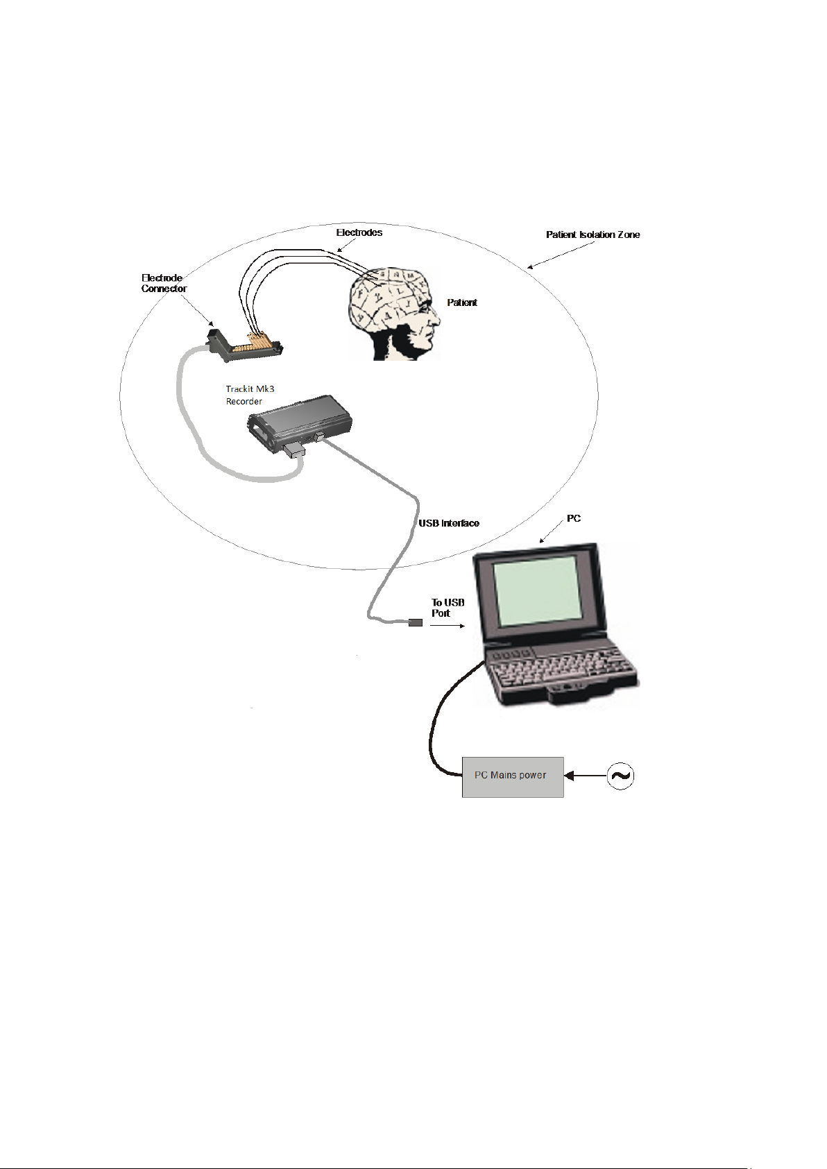
Below is an overview diagram showing the principal compon ents when conn ected to a PC during
system set up.
Figure 1 Connecting the Trackit Mk3 for re c order set-up
List of parts supplied by Lifelines:
Trackit Mk3 recorder plus bag
Patient Connec tion Unit (PCU), for e lectrode connection
1 x CF flash card (optional)
3 x PP3 batteries (optional)
PC USB cables
List of optional parts supplied by third parties:
Host PC/laptop with p ower cable
CF cards
Batteries
Battery charger
17
Page 18
Trackit Mk3 User Manual
Trackit
RJ45 Connection
3.2 Connecting the Trackit Mk3
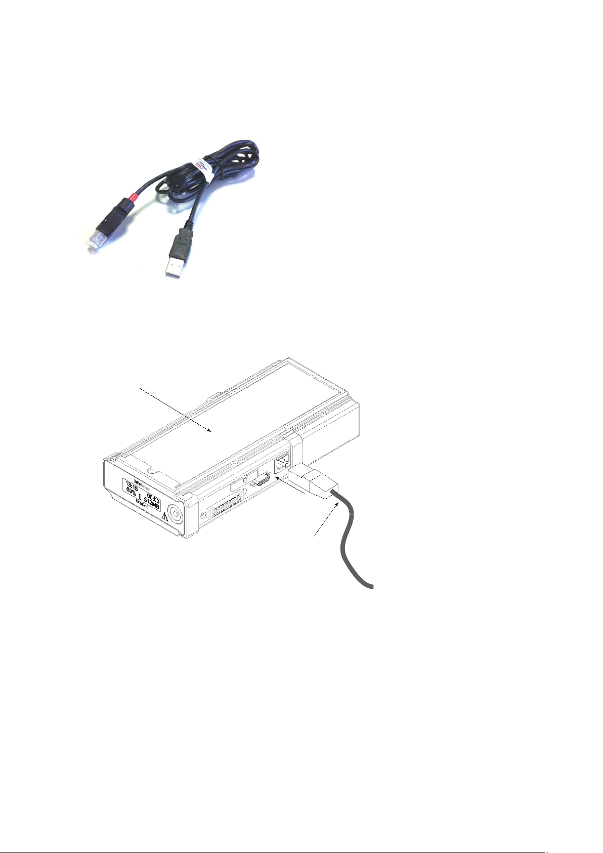
The Trackit Mk3 is simply plugged into the PC USB port usin g th e c a ble s upplied. Note: only u s e
the USB cable part number 1277 (with the red tip) for the Trackit Mk3 as shown below:
Figure 2 Connecting to the Trackit Mk3 recorder
The necessary U SB drivers will be found on the installation CD. Upon first connection of the Trackit
Mk3 to the PC USB por t, at the Windows promp t, browse to the folder CD Drive:\USB Drivers. From
there, Windows will find the correct dr ivers for the version of Windows being used.
3.3 Switching on
Turn on the unit by pressing th e button on the right of the LCD display on the front panel of the recorder.
18
Page 19
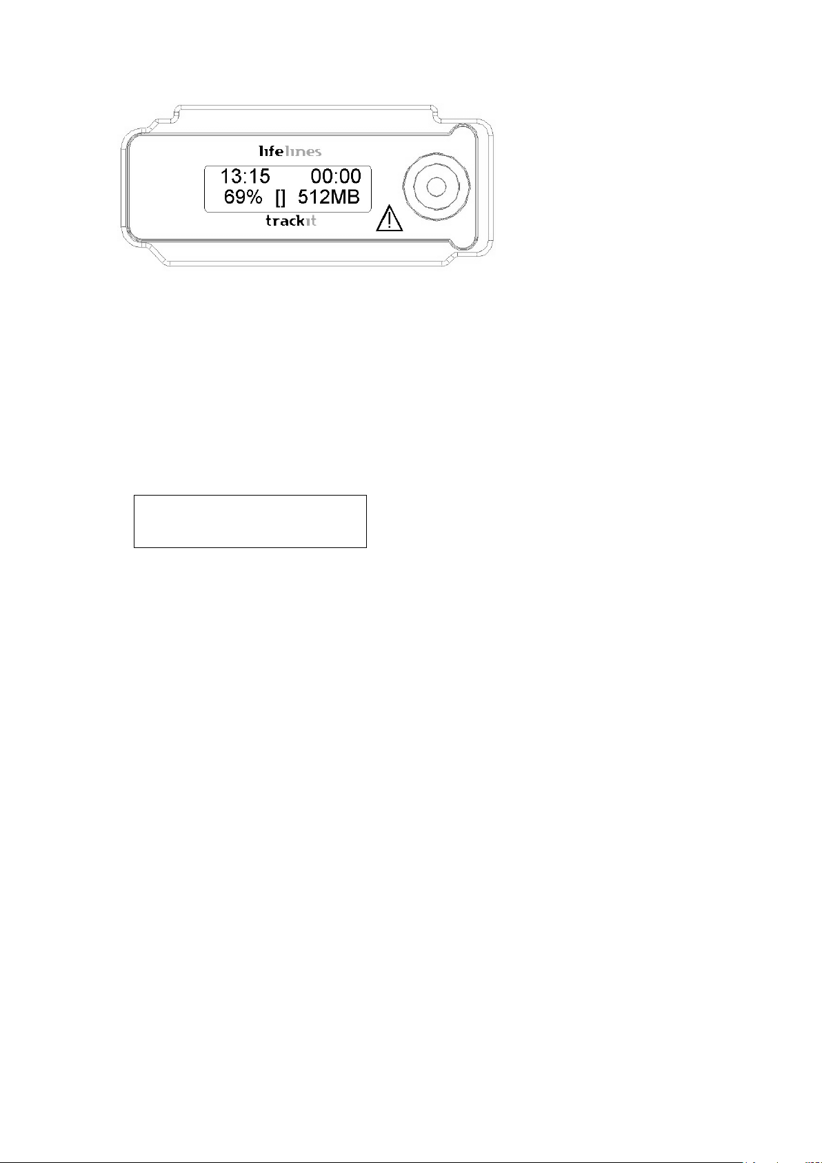
Trackit Mk3 User Manual
to the host during s etup.
Recording time of this recording
If not recording, ‘00:00’ is dis played.
sent, ‘0’ is displayed.
tery capacity).
Rear-door open warning symbol
Flashes when the rear battery door is open .
Internal beeper
Warning of low batte r y or rear-door open.
Special recording mode
Timed or sampled recordings a re indicated by the symbol
S.
Recording to card
The symbol R next to card capacity.
Refer to Appendix 5 for further inform ation on Bluetooth.
2 1 4 5 3 6
Figure 3 Trackit Mk3 recorder: front panel
After several seconds the LCD display indicates that Trackit Mk3 is performing a self-test for system integrity. On completion of th e s elf-test the LCD indicates the status of the Tr a ckit Mk3 recorder.
Indicators
The following ind ic a tors are available depending on Trackit Mk3 status:
Û~11:49 Û~00:00
Û~71 %âÛ Û~2049M
Figure 4 The Trackit Mk3 display
Key:
1 Time of day
2 Recording time
3 Battery capacity remaining
4 Internal Bluetooth on/off
5 Rear door open warning
6 CF Card capacity remaining
Time of day
Disk capacity Remaining storage capacity in MB. If there is no card pre-
Battery capacity Approximate battery capacity remaining (as % of full bat-
The battery-backed, real tim e clock which is syn chronized
3.4 Warning symbols on the display
Low card capacity Symbol L accompanied by beep in g every 30 seconds.
Internal Blu e tooth on/off When the Internal Bluetooth option is fitted to the Trackit
Mk3, the unit will display whether it is enabled or disabled
with a large ‘B’ (enabled) or small ‘β’ (disabled) next to
the ‘%’ indication. To toggle the current selection the
pushbutton is pressed 5 times w ithin 3 seconds. The display will change to indic a te the new state.
19
Page 20
Trackit Mk3 User Manual
4 The setup software
The setup softw a r e is available on CD. A r eadme file describes installation. Check with your distributor or Lifelines if a newer version of software is available.
Trackit setup software is supported on Microsoft Window s 2000 ( w ith SP2), Windows XP, Windows
Vista and Windows 7.
When Trackit Mk3 is connected to the h ost PC, the software a llows the user to define p a rameters
for the recording, such as recording montage, start time and stop time, m ode of recording etc .
The setup softw a r e has the following func tions:
Define signal type s : create labels to atta c h to inputs
Attach the desired signal ty pe ( la bel) to the recording input. For ex a m ple , input 1 with a signal
type FP1
Create a recording montage and down load it to the recorder
Perform a calibra tion of the inputs
View signals online and adjust display parameters such as chart speed and display sensitivity
Start and stop a Trackit recording session
4.1 Setting up a recording protocol
Summary
Step 1 Define the patient ID
Step 2 Define the signals
Step 3 Define the inputs
Step 4 Define the recording channels
Step 5 Activate the r ec ording control
Step 6 Connect the Trackit Mk3 for setup
Step 7 Check Trackit Mk3 status
Step 8 Start a recording
Step 9 View the ongoing EEG tra c es
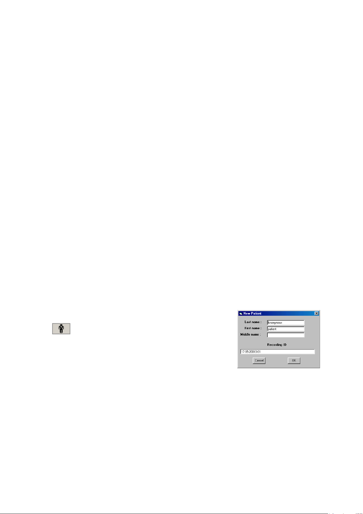
Step 1 Define the patient ID
1 Select the New patient icon on th e toolbar.
New Patient icon
2 Enter the patent name and Recording ID into the New Patient di-
alog.
This information is saved with the r ecording setup for d ownload
to the recorder in a future recording.
Figure 5 New Patient dialog
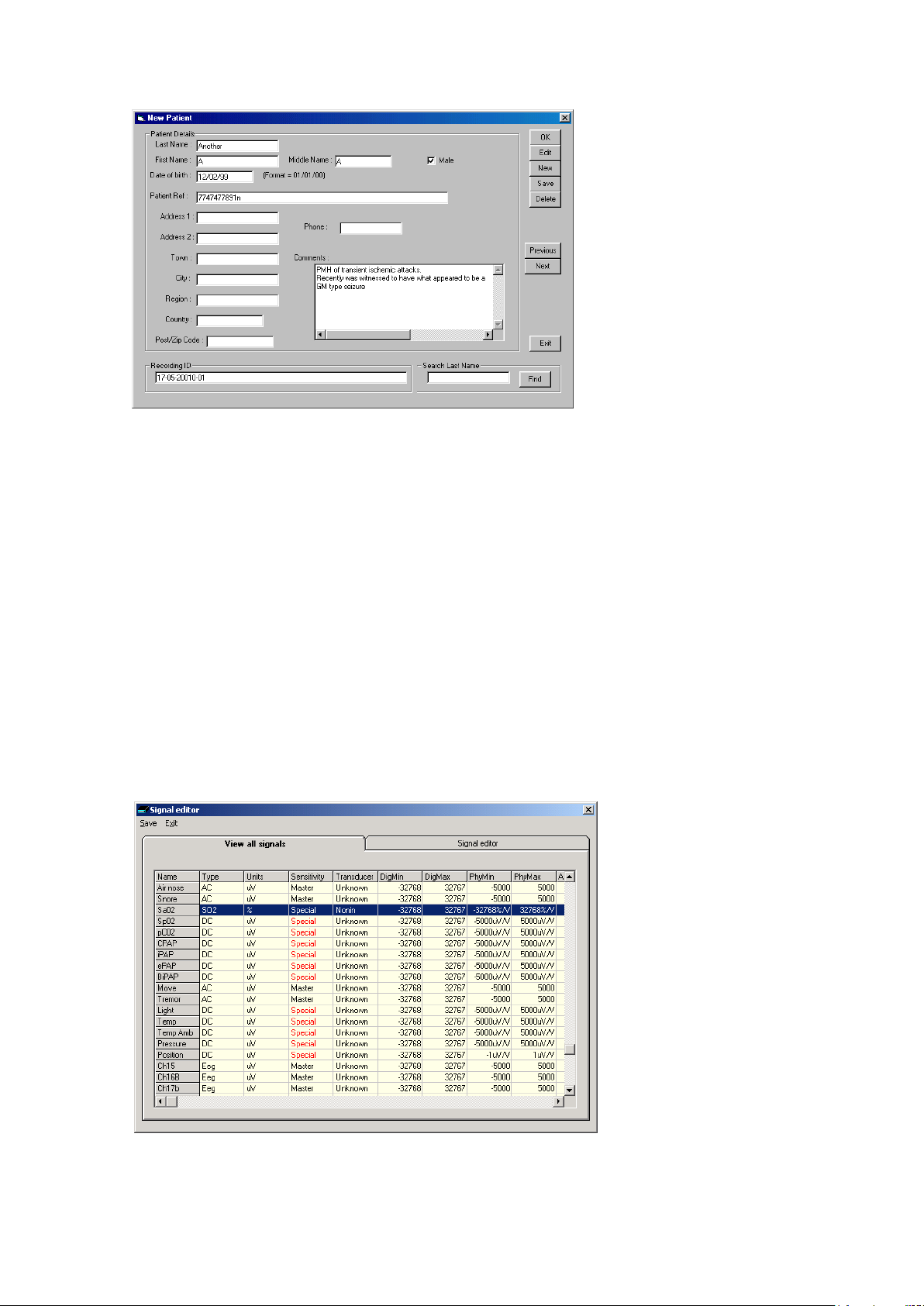
It is possible to con figure the system to use a patient database (Figure 6) instead of the simple dialog shown above .
20
Page 21
Trackit Mk3 User Manual
Figure 6 New Patient database
The database allow s you to enter more exten s ive information about the patient and recording, and
save it for future refer ence. See the section entitled ‘Adv a nced options’.
Step 2 Define the signals
Defining signals is usually done once only – before using Track it Mk3 for th e first time. The Trackit
Mk3 recorder arrives w ith a default set of signals that should suffice for most applications in ambulatory EEG, hen ce it may only necessa r y to a dd s ig nal types for polygraphic recordings (airflow,
respiration etc).
If for any reason the signals have not been created, it is necessary to define all the signals (labels)
that are to be used f or m ontage creation in Step 3. The signal editor allows the creation of up to 64
distinct signals ranging from the standard 10/20 EEG signals such as FP1 O2, to Respiration, Pulse
and other polygraphy inpu ts .
Step 3 explains how to calib r ate an AUX input.
To define a signal:
1 Click the View all signals tab in the Signal editor dialog box . See Figure 7.
Figure 7 Signal list
21
Page 22
Trackit Mk3 User Manual
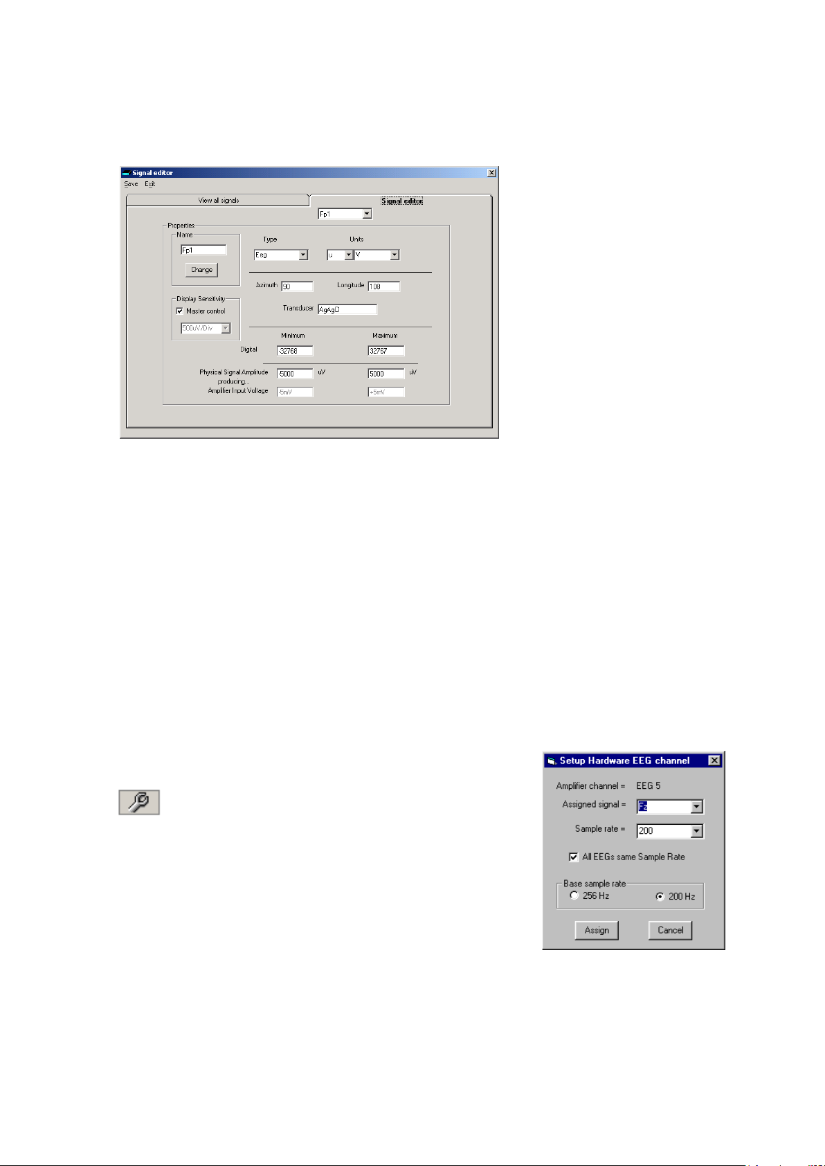
2 Double click on the signal you want to edit. This brings up the Signal editor tab), allowing you to
create a relevant signal or label to be en te red into the signa l lis t.
Figure 8 Signal e diting tool
3 Type in the Signal name (e.g. Fp1). N ote that for EEG signals this must be case-sensitive.
4 Select a signal type (in this case EEG).
5 Click on the Change button. The signal is now entered into the list under the View a ll signals
tab.
6 If the signal is not an EEG signal, it ma y be necessary to insert a display sensitivity value by un -
checking the M aster control check box.
Signals that ha ve been defined with their own independent sensitivities appear in red in the
trace display. F urther editing an d ch a nges to these sensitivity values in th e trace display will be
saved back into the signal library.
Caution: editing signals that are already used in an a c tive montage may r ender that
montage invali d. Y ou will need to re-enter the original m ontage in the Set-up rec ord-
ing tabbed dialog box – see steps 3, 4 an d 5.
Step 3 Define the inputs
1 Select the Spanner icon on the toolb a r . This opens the tabbed
Setup Recording dialog.
Spanner icon
2 Under the Amplifier Channels tab select the signals (la bels ) to be
attached to the phy sical inputs.
For example, EEG input 1 may require the label Fp1 and so on
according to the standard 10/ 20 nomenclature.
Double click the ch ann el name and s elect the r elevant sig nal label
from the Setup Hardwar e EE G cha nnel dialog.
Figure 9 EEG setup
22
Page 23
Trackit Mk3 User Manual
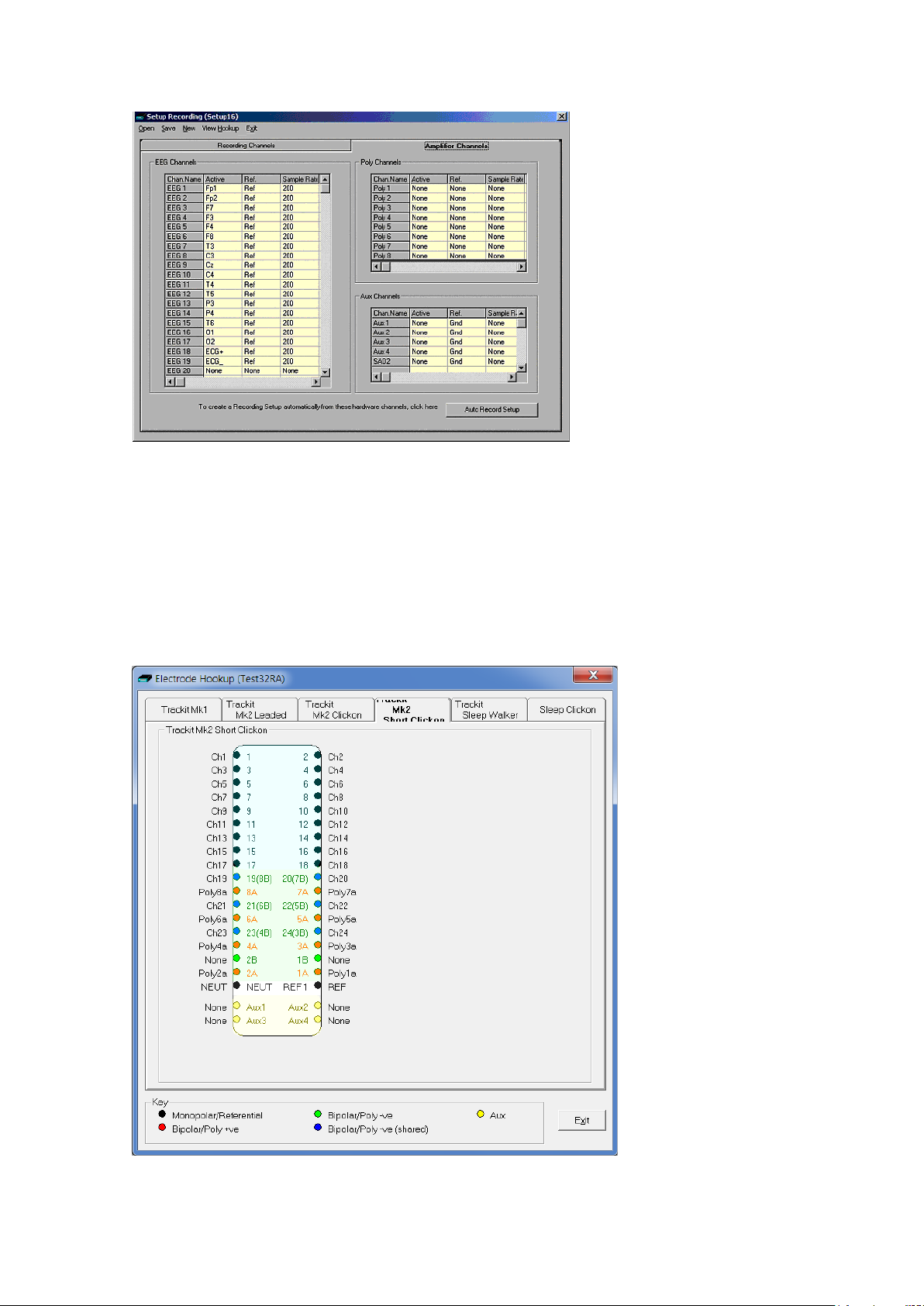
Figure 10 Setup Re c ording dialog
The order of the sig nal labels in the pull dow n list is the same as the order of the signals in the signal list defined us ing the signal-editin g tool.
To see the user-defined la b els (signals) on the inputs, click on V iew Hook-up in the Menu Bar. See
Figure 11.
The View Hookup display shows all the currently av a ilable PCU options. C lick on the appropriate tab
to access the specific type.
Figure 11 View Hookup
23
Page 24

Trackit Mk3 User Manual
Amplifier setup: amplifier setup ac tivates the recordin g inputs in preparation for a recording. For
most applications you n eed per form amplifier setup on ly once – when the sy stem is first installed –
since the amplifier setup is s a ved with the recording montage for f uture recall and usage. See Step
4 below.
If you want to use the recording ch a nnel order defined in amplifier setup, click on Auto Record
Setup in the Setu p R e c or d ing dialog box. You can then skip Step 4 (Define the recording channels).
Overall sampling rate: you can sele c t the overall sampling ra te for EEG channels from the Setup
Hardware EEG dialog (Figure 9). Once a sampling rate has been selec ted f or on e EEG input, you
can apply it to all EE G inputs by putting a checkmark against ‘All EEGs same Sample Rate’. If there
is no checkmark, you can select different sample rates on each EEG input – useful if you want to
apply an EOG signal to an EEG input.
Independent sample rates: if the independent sample rates feature is enabled in the Trackit
Mk3 firmware, it may be activated when required from a checkbox in th e Options dialog box
(choose View > O ther Options).
Notes:
1 Not all review software supports independent sample rates . Check with the vendor that your re-
view software does suppor t th em .
2 The Trackit Mk3 firmware must b revision 2.1.X or la te r .
3 It may be necessary to enter an unloc k code into Trackit Mk3 to enable this feature. If the fea-
ture is not enabled, a warning m es s a ge a ppea r s w hen a setup is sent to the recorder.
To enable multiple independent sample rates in the recorder:
1 Click on Trackit Control Panel in th e Trackit toolbar.
2 Click on Advanced Operations, then choose Configu r a tion from the Setting s Menu.
3 Copy the key code and email it to your Lifelines re pr esentative stating that you wish to have the
multiple independent sample r a te f ea ture enabled. You will then r ec eiv e ba c k an activation code
that you shou ld c op y and paste into the empty Trackit configur ation string field .
4 Press the Set Trackit button to enable the feature.
5 Choose Other Options from the Vie w Menu, and put a checkmark in the Allow Multi-sample rates
check box.
Poly and AUX inputs: poly inputs are low-le vel inputs, just lik e the EEG inputs, but dif fer in that
they can be set to either referential (EEG mode), bipolar AC or bipolar DC. They are ideal for p olygraphic signals such as respiration, airflow, EKG, body position (DC mode) etc. See the table in appendix 2 describing the inpu ts a nd their application.
The AUX inputs are high-level DC , and should not be us ed for low-level signals obtained from
transducers such as passive respiration sensors (piezo electric), airflow thermocouples etc. The
AUX inputs are designed to receiv e a high-level isolated DC signal (calibra ted output from a CPAP
machine, oxygen saturation meter etc).
To calibrate an AUX input to reflect a required unit of scale for a given voltage input use the signal
editor - see Figure 8). Select the appropriate u nits, e.g. %, or mm Hg, and enter the Physical Signal Amplitude required to generate the Amplifier Input Voltage.
Step 4 Define the recording channels
Step 4 can usually be skipped, s in c e the Auto Record Setup button w ill copy what you have defined
under the inputs in Step 3 into the list of recording chan nels.
However, you can defin e an d s a ve recording montages for specific recording needs, and recall them for f uture usage. You can
define up to 40 recording cha nnels in a montage.
Creating a montag e follows the same principle as the signal
creation and input definition tool: c lick on the channel number
to define the active and reference label of choice. See Figure
12.
Figure 12 Channel setup
24
Page 25
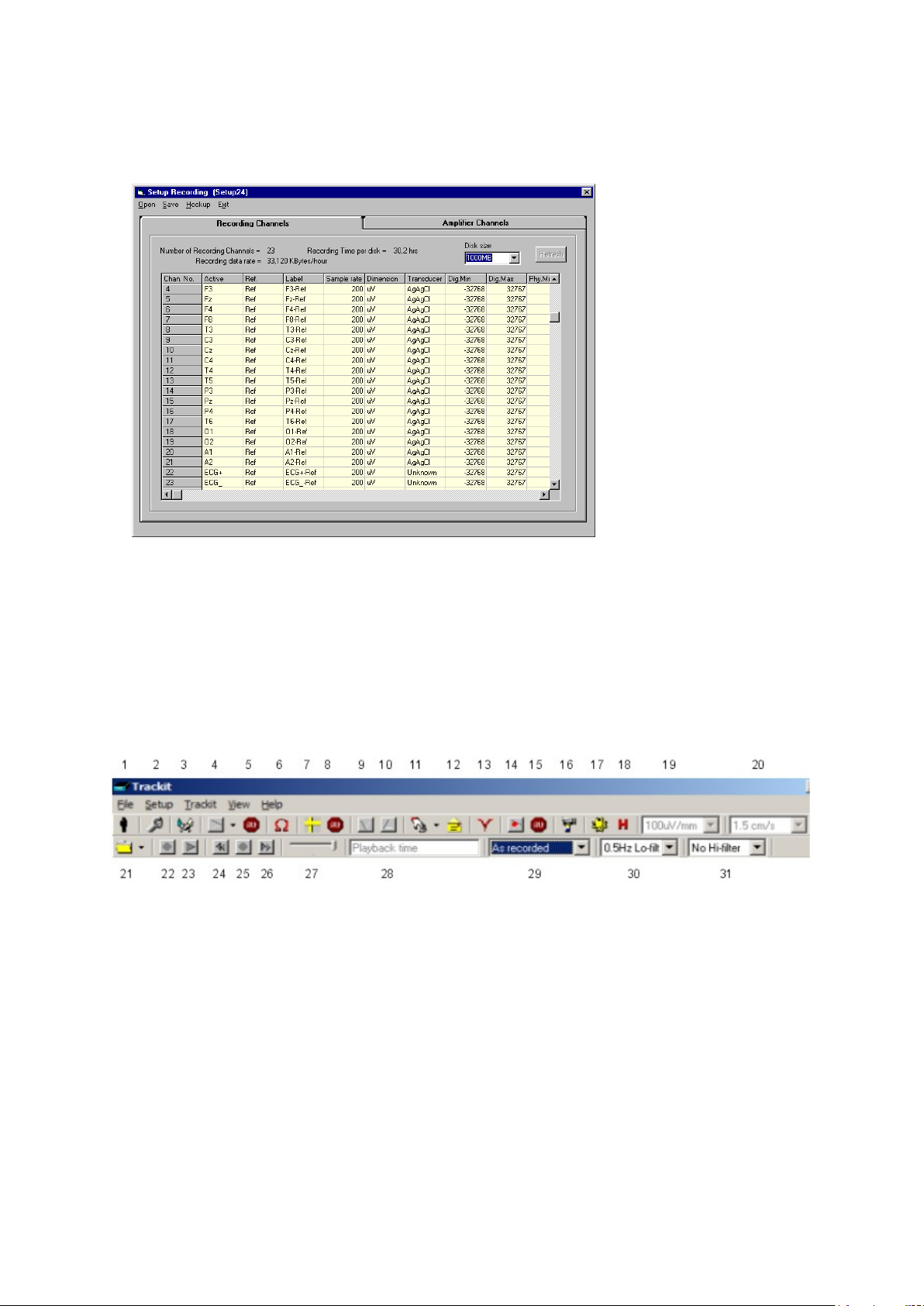
Key:
1 New Patient
2 Setup Recording
3 Trackit Control Panel
4 Ongoings On
5 Ongoings Off
6 Impedance Check On
7 Calibration On
8 Calibration Off
9 Page Down
10 Page Up
11 Get Trackit Events
12 Email Events L is t
13 Notch Filter On/Off
14 PC Record On
15 PC Record Off
16 Videometry (optional)
17 Photic Stimulation
18 Hyperventilation
19 Vertical sensi tivity
20 Chart speed
21 Open files for playback
22 Stop playback
23 Start playback
24 Page back
25 Stop paging
26 Page forward
27 Paging speed
28 Playback time
29 Montage selection
30 Lo-filter select ion
31 Hi-filter selection
An example of a r e c or d ing montage is shown in Figure 13 below.
Trackit Mk3 User Manual
Figure 13 Recordi ng Channel edit ing
4.2 Configuring the recorder
When you have f inished setting up the rec or d ing protocol, connect the Trackit Mk3 recorder to the
host computer. Steps 5 to 9 describe c on figuration and set-up of an ambulatory EEG.
Step 5 Activate the recording control
From the Track it toolbar (Figure 14) select the Trackit Contr ol Panel (‘handshake’) icon.
Figure 14 Trackit software toolbar
25
Page 26
Trackit Mk3 User Manual
not.
Ext Supply
Shows whether the Trackit Mk3 is being powered by the medical grade DC
power supply.
Battery
Shows if a battery is pr e s ent or not.
CF card
Shows whether a CF card is present and its capacity.
corder.
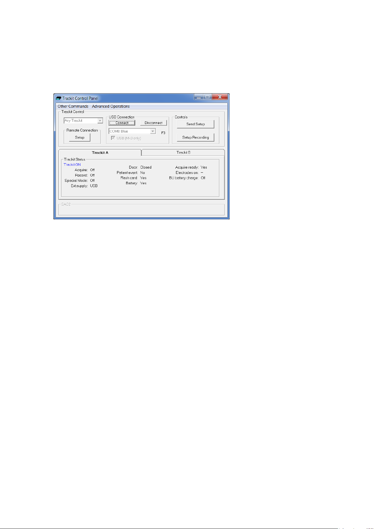
Clicking on the ‘ handshake’ icon brings up the Trackit Control Panel dialog box (Figure 15).
Step 6 Connect Trackit Mk3 for setup
Check that the Trackit Mk3 recorder is switched on and that the cables are all con nected properly.
In the Trackit C ontrol Panel either select the USB option for the Mk 3 Tr a c kit or check that the cor rect COM port is selected an d click on the Connect button.
Figure 15 Trackit Control Panel
After a couple of s e c onds Trackit Statu s shows ‘Trackit Online’ and the software displays the recording paramete r s loaded into Trackit Mk3 in the status bar at the bottom of the screen.
Trackit Status a lso shows whether th e b a tte r y and PC card are present, whether the door is open
or closed, whether the electrode conn ec tor is attached, a nd the recording status of the device.
The ‘F’ or ‘F1’ next to the port selection box indicates that the fast connection speed, which is available with the Trac kit Mk2, is being used. This will be automatica lly enabled as long as the PC serial
port hardware is capable of operating at 230 kBaud. ‘F2’ a nd ‘F3’ are displayed to indicate the substantially fa s te r c onnection speeds av a ila b le for the Mk3 USB interface.
Step 7 Check Trackit status
Use the Trackit C ontrol Panel to check that the Trackit Mk3 recorder is correctly online. The Trackit
Status part of th e Control Panel gives you the following information:
Acquire – on or off
Record – on or off Shows whether or not the Trackit Mk3 is recording data to flash card.
Shows whether an online view of the data on the host PC is takin g plac e or
Status Shows how much ba tte r y life is left.
Patient event Shows that the external patient event marker is connected.
Door Shows whether the door to the CF card and battery is open or closed.
Electrodes connected Shows that the P a tie nt Connection Unit is connected to the recorder (Mk1).
Acquire ready
26
Shows that a valid recording setup has been loaded to the Trackit Mk3 re-
Page 27
Trackit Mk3 User Manual
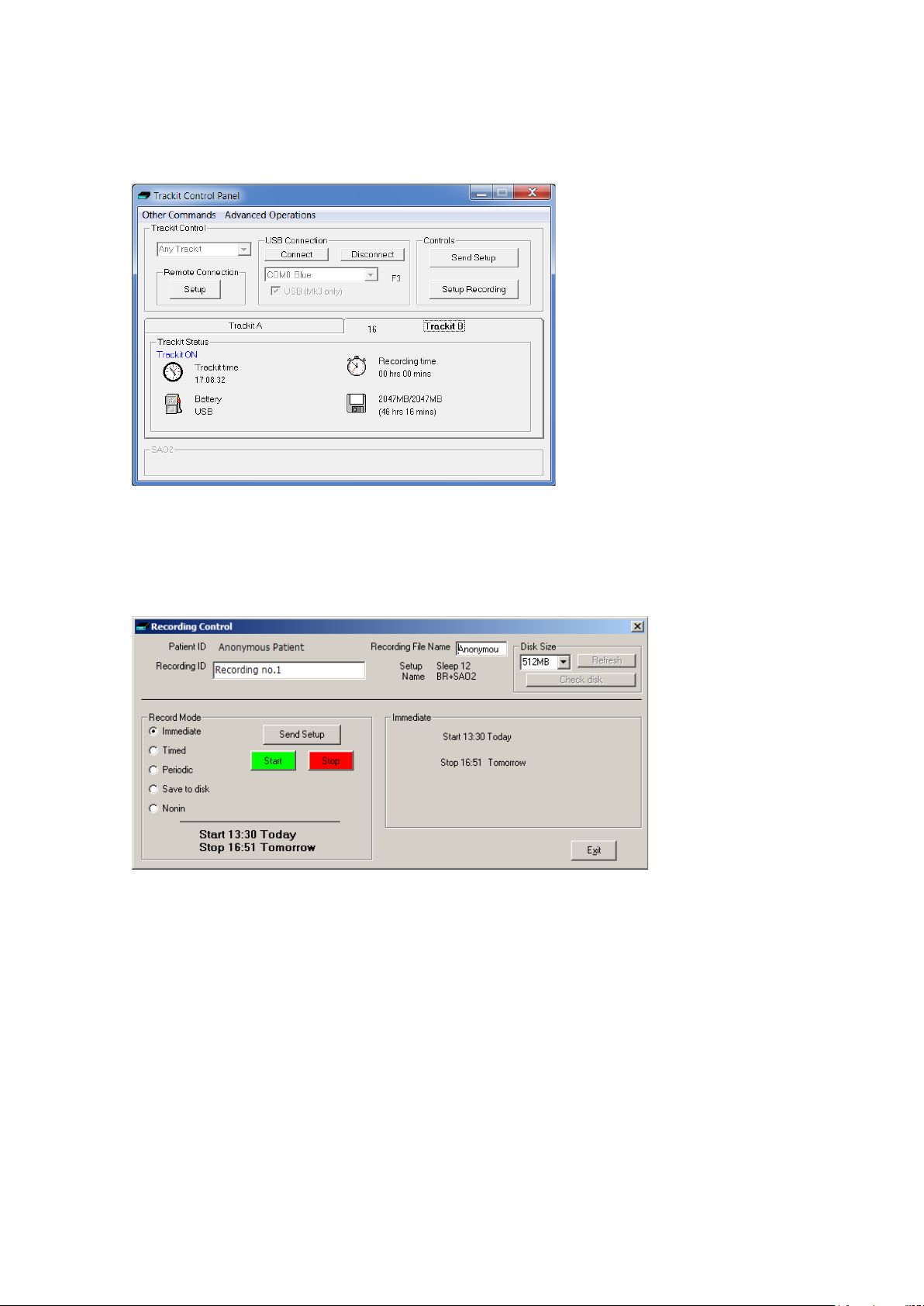
Note that further status information is available on th e 2nd tab shown below. This includes Trackit
Mk3 time, Battery capacity, Recording time a nd CF card MB total an d MB remaining.
Figure 16 Trackit status ' B'
Step 8 Start a recording
Click on the Setup Recording button in the Trackit Control Panel to open the Recording Control dialog box (Figure 17). The patient’s name and the file name for the recording are displayed.
Figure 17 Recordi ng Control
You can accept the default filename, or you can insert a filename (up to 8 characters long) of your
own choosing.
Default file names
To make the recording file name the same as the patient name:
1 Choose Other Options from the Vie w Menu.
2 Put a checkmark by Default to Patient Name.
3 Click on Exit.
Ways of starting a recording
You now have four ways to start a recording:
Immediate
Timed
27
Page 28
Trackit Mk3 User Manual
Periodic
Save to Disk
Nonin
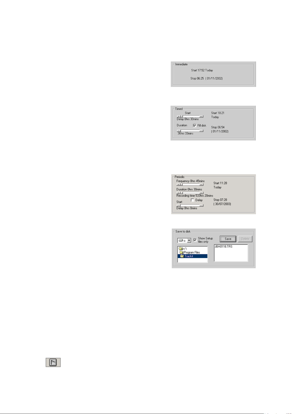
Immediate: the recording starts as soon as you click
Send Setup, then Start (see Figure 17). Recording finishes
when the Trackit Mk3 is turned off.
1 Under Record Mode, choose Immediate.
2 Click the Send Setup button, then the Start button.
Timed: Trackit Mk3 records for a specified period of time.
1 Under Record Mode, choose Timed.
2 In the Recording Control dialog box, s e t a start time
for the recording using the Start slider.
3 Either put a checkmark by ‘Fill Disk’, or use the Dura-
tion slider to tell Trackit Mk3 how long to record for.
4 Click the Send Setup button.
Periodic: Trackit Mk3 records for specified periods of time at a defined interval (eg for pe r iod s of
30 minutes, with a 45-minute interval):
1 Under Record Mode, choose Periodic.
2 Use the frequency and duration sliders to define the
length of the recording period, a nd the interval be-
tween periods.
3 For a delayed start (eg in an MSLT study), put a
checkmark by the Delay box, and use the Start slider
to set a start time for the recording.
4 Click the Send Setup button, then the Start button.
Save to disk: a setup is created, then saved on the flash
card for use in a later recording. This is particularly useful
for home sleep recordings where the patient can switch on
the recorder (and so start the recording) just before going
to bed.
1 Create a setup in the normal way, with patient name an d recording chann els.
2 Place the flash card in the flash card reader in the host PC.
3 Under Record Mode, choose Save to disk. The setup is sav ed on t h e flash card as a *.trs (trackit
recording setup ) file. The name of the s e tup file is the patient’s last name.
4 The Trackit Mk3 recorder starts recording automatically, us ing this setup file, when it is
switched on.
Nonin: Recording starts as soon as the Nonin SaO2 probe is connected an d a ttached.
To initiate an imm e diate online recording
1 Click on the Send Setup button. Wa it for the setup to upload t o the Trackit Mk3 recorder. This
should take a few seconds.
2
In the Trackit toolba r , click the Ongoings O n icon to view the traces.
3 Make sure what is seen is what should be recorded.
28
Page 29
Trackit Mk3 User Manual
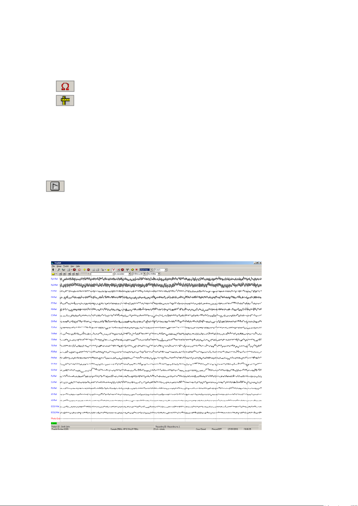
toolbar.
the Ongoings On ic on in the Trackit toolba r
Depending on the sam ple rate and number of channels selec ted it may be necessary to observe
groups of channels separa tely , e.g. with 256 Hz sampling with 24 recording channels it is only
possible to view 12 c hannels at a time.
To switch from the upper to the lower group, use the u p and down arrow keys on the toolbar, or
choose Trace Page from the Trackit Menu.
4
To perform an impedance ch ec k, click on the Impedance Check icon 1n the Trackit
5
To perform a calibration, click on th e Calibration icon in th e Trackit toolbar.
6 Click the Start button in the Recording Control dialog. Wait for the prompts to start a recording.
If there is an old file on the card the sy s tem a s ks you whether the file should be overw r itt en.
If there is a file on the card belonging to the same patient, and the file is < 24 hours old, the
recording will be appended to th e existing file. (To enable or disable this feature, > Track it Con-
trol Panel > Adva nced Operations > S ettings > Set Trackit defa ults)
The Trackit Mk3 is now recording to the flash car d and w ill c ontinue until the ca rd is full or the batteries have run low on power.
Step 9 View the ongoing EEG traces
To view the ongoing EEG traces before or after rec ording to card has started, clic k on
When you do this, one of three things occur:
If the Trackit Mk3 is connected to the PC, and has been sent a valid rec ording setup, the traces
appear wiping from le ft to right across th e d is p la y.
If the Trackit Mk3 is already recording and still connected to the PC, the traces appear as soon
as the Ongoings On icon is pressed.
If the Trackit Mk3 is already recording and is then reconnected to the PC, the system as ks for
the recording setup held in the Trackit Mk3 recorder before displaying the traces.
Figure 18 Ongoin g tr a c e display
29
Page 30
Trackit Mk3 User Manual
The primary pu r p os e of viewing the ongoin g tr aces is to verify tha t the signals are correct before
starting an ambulatory recording.
You can view selected traces in blocks of 12 channels (at 256Hz or 200H z) or 16 channels (at
128Hz) for the Mk 1 or up to 40 channels with the Mk 2. Or select the number of tr a c es for display
by choosing Nu m be r of Traces from the Trackit Menu.
Page Up and Page Down on the toolbar allow you to switch between the top and bottom group of
traces.
Sensitivity, Chart speed and Hi/Lo filte r s: as is often the case when viewing a live trace display, the sensitivity, chart speed and filters n eed be adjusted for optimal viewing. Use the drop
down lists on the too lb a r.
To adjust the display parameters for an individual channel, click on the
channel label. This displays a dialog box for that chan nel, with a checkbox for master con trol, trace On or Off, and Numeric. Click on Numeric
if you want the numeric value displa yed under the label. This ca n be
useful when for displaying units such as mmHg or degrees C.
When a channel is under individual channel control the label is d epicted
in red. When display of that channel is turned off, the label is greyed
out.
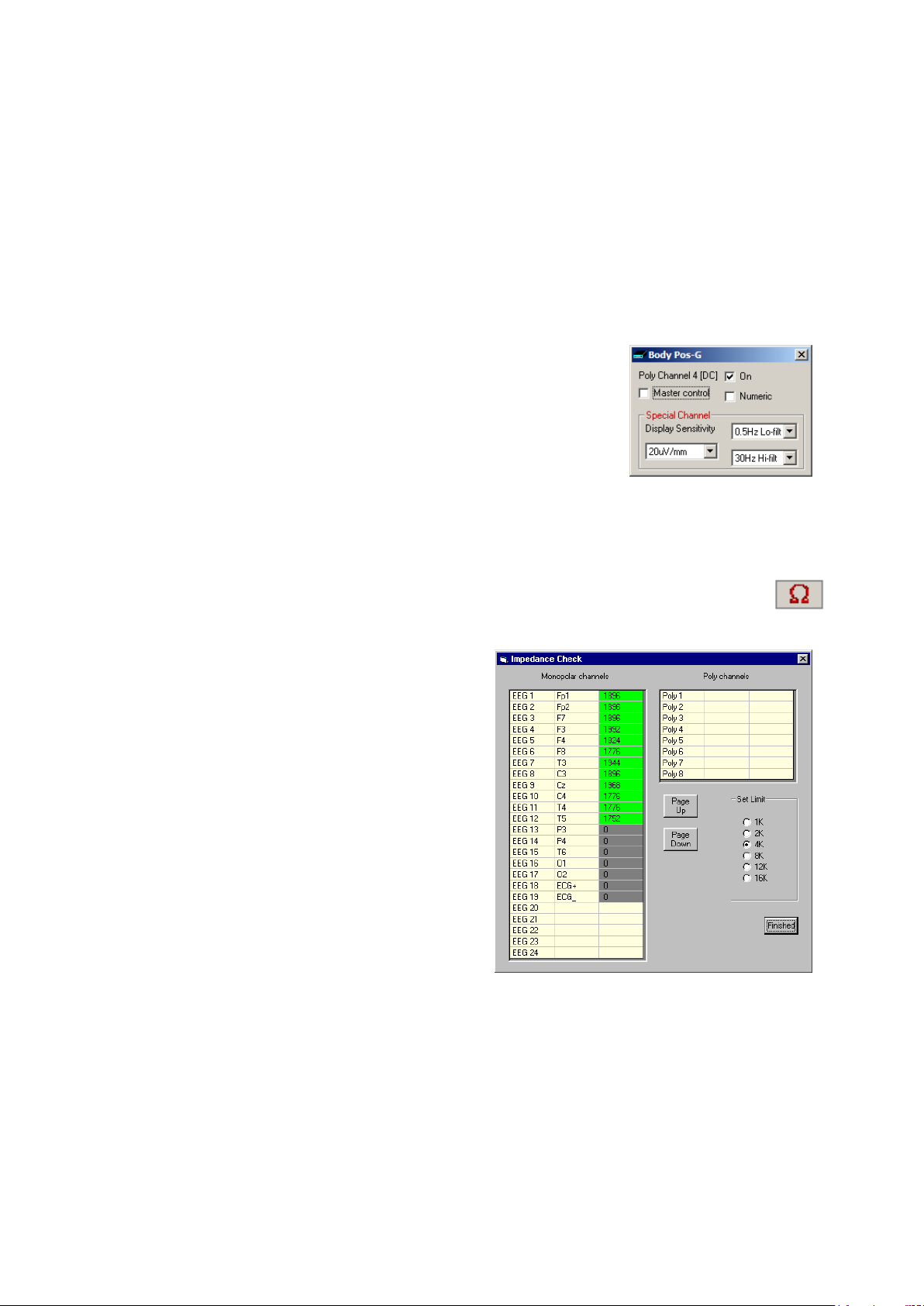
Impedance check: to carry out an impedance check, click on the impedance check icon
on the Trackit toolba r .
If recording to card has s tarted , the impedance
check is display ed on the trace display w ith an impedance check event.
The impedance check works via pass/fail threshold
selection. See Figure 20. Impedance values above
the selected threshold (fail) are displayed on a red
background. Values below (pass) are displayed on a
green background
Figure 20 Impeda nc e check
Figure 19 Adjust display parameters
30
Page 31
Trackit Mk3 User Manual
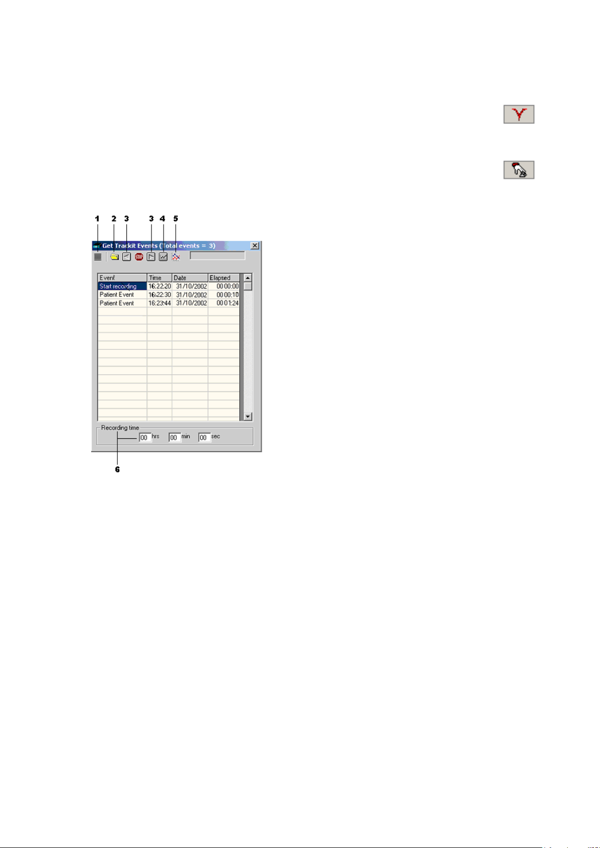
Trackit events: to view all recorded events online, click on the Get Trackit Events icon
Notch filter: to set a notch filter, use Other Options fr om the View Menu. Notch filters are either
50Hz or 60Hz depending on where the system is to be used (USA 60Hz; Europe 50H z).
To activate the notch filter, click on th e N otch Filter icon in the T r ackit toolbar.
in the Trackit toolba r .
Events are displayed in the online event viewer with a description an d tim e .
Key:
1 Opens the list of event types
2 Opens an event file for an older re-
cording
3 Navigate forwards or backwards
4 Selects the best trace resolution
5 Selects the max. number of traces
6 Enter a ‘Go to’ time here
Figure 21 The onli ne event viewer
The event list allow s the user not only to see when events took place, but to also view the data behind those events.
To display a page of EEG around an even t of interest, double click on the event in the list. The
speed with which the data is displayed depends on whether the Ma ximum Number of Traces and
Best Trace Resolution icon s a r e s elec ted. If no buttons are selected, the displayed traces are the
same as in the live tr a ce display. If both bu ttons are selected then the max imum number of recording channels with best trace res olution will be displayed.
To navigate forwards or backwards, press the forward or backward arrow buttons. Or you can go to
a particular time in the recording by en te r ing the time (as hrs, min, sec) in the recording time
fields. See Figure 21 above.
You can replay EEG live from the event list while a recording is taking place or offline by opening
an event file from a previou s r ec or din g.
4.3 Montage Editor
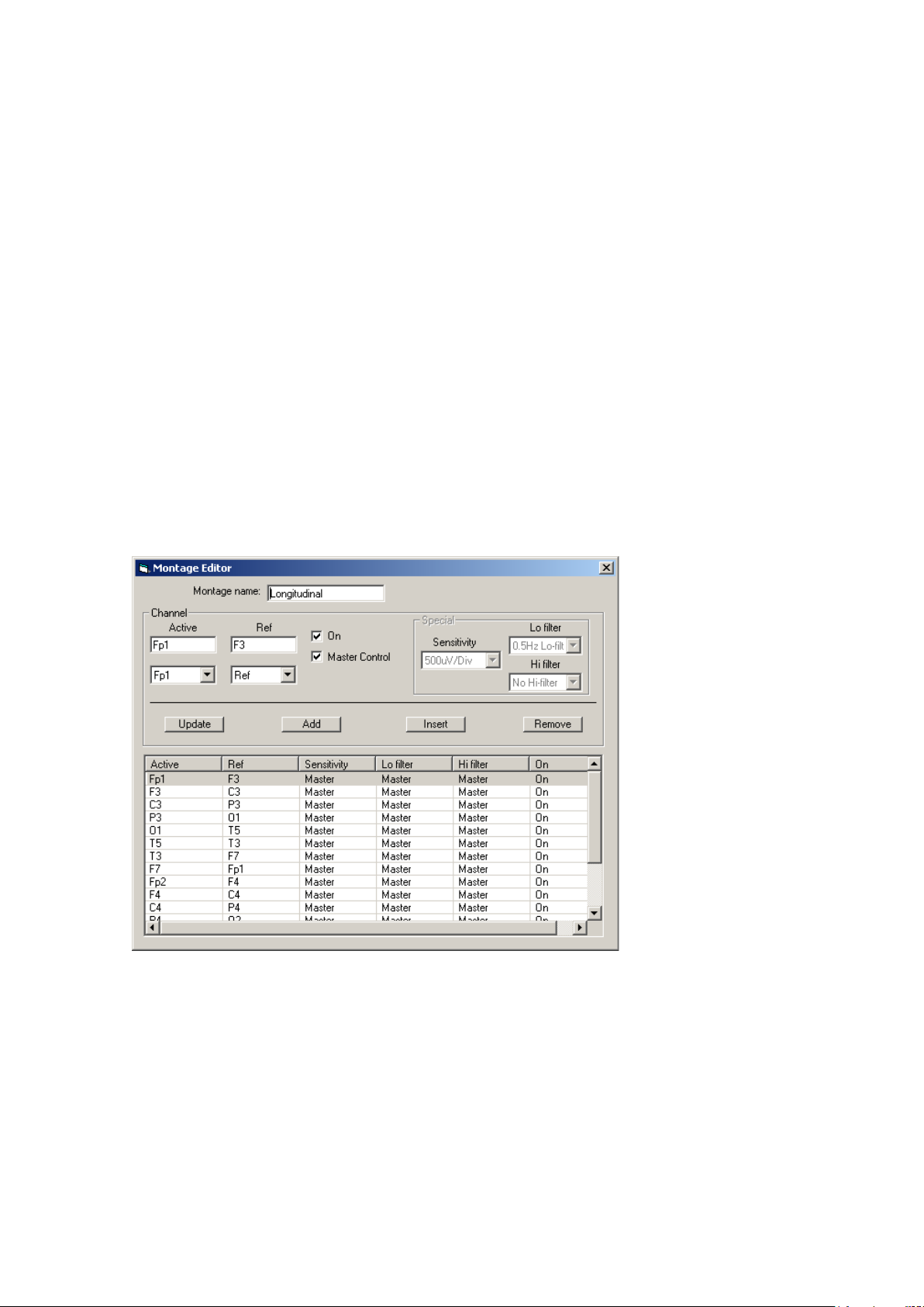
This is available via the Setup | Montage menu on the main s c reen, and displays th e Montage Editor as shown in Figure 22 below.
The Montage Editor a llows the setting-up of 16 user montages and the As-recor ded montage. Note
that the As-record ed m ontage can only ha ve its channel on/off a nd channel master/special control
31
Page 32
Trackit Mk3 User Manual
edited (and if special, the channel sensitivity an d filters). All the other 16 user montages a r e fully
definable and can have th e following parameters set for each c hannel:
1. Active channel name. This is either chosen f rom the drop-down list representing the current Signal Library signals, or typed in directly.
2. Ref. channel name. T his is either chosen from the drop-down list representing the c urrent Signal
Library signals, plus Ref and Gnd, or typed in directly.
3. Channel On or Off. If of f, the channel label is gr eyed-out and no tra ce is displayed.
4. Master or Special Control. If Special, then the Sensitivity, Low Filter and High Filter c an be set.
Additional controls are provided to allow:
5. Update. Copies the cur r e nt settings into the currently selected c hannel.
6. Add. This adds a channel to the end of the Montage list.
7. Insert. This insert a c hannel above the curre ntly selected channel.
8. Remove. This removes the currently selected channel.
9. Montage name.
If anything is ch anged, an option is presented to save all cha nges to disk or not. If not saved,
changes are only temporary .
Note that some of the montage parameter s can be changed outs ide the Montage Editor, b y clicking
on a channel label to br ing up the Channe l Information win dow. These changes are on ly temporary
(although you c an save them later by subseq uently going into th e M ontage Editor).
Figure 22 Montage Editor
32
Page 33
Trackit Mk3 User Manual
5 The ambulatory recording
Once Trackit Mk3 has been set up for an ambulatory recording, a nd a recording has been initiated,
you can change batteries and cards without interfering w ith the recording, so long as you observ e
the rules for changing batt er ies a nd cards outlined below.
5.1 Changing batteries and cards
WARNING. if the Trackit Mk3 recorder is not likely to be used for some time, the batteries should be removed.
To change card s an d ba tteries during a rec or d ing, following a low battery or card warning, carry
out the following procedures.
Changing batteries
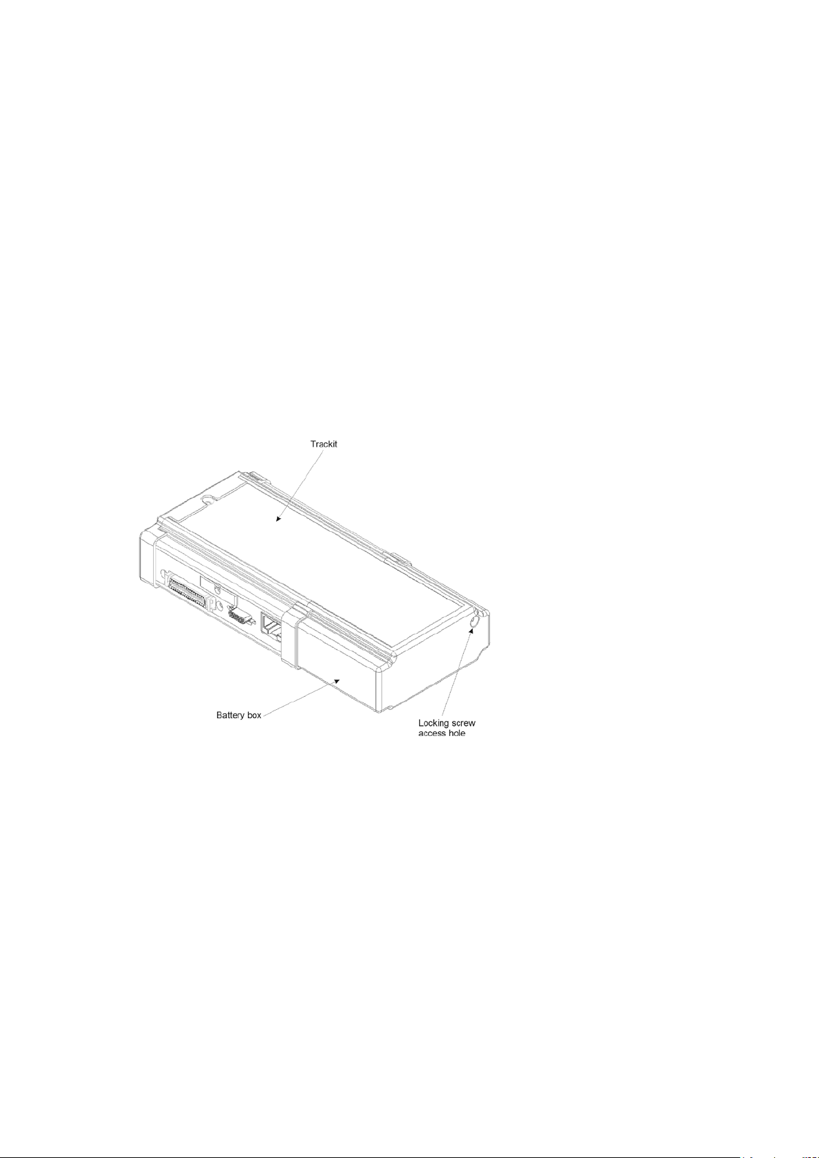
1 Open the Trackit Mk3 rear Battery b ox/door with the spec ial tool provided. The unit’s warning
beeper will sound a nd the Door Open symbol will flash on the disp la y.
Figure 23 Opening the rear battery box/door
2 Different battery types
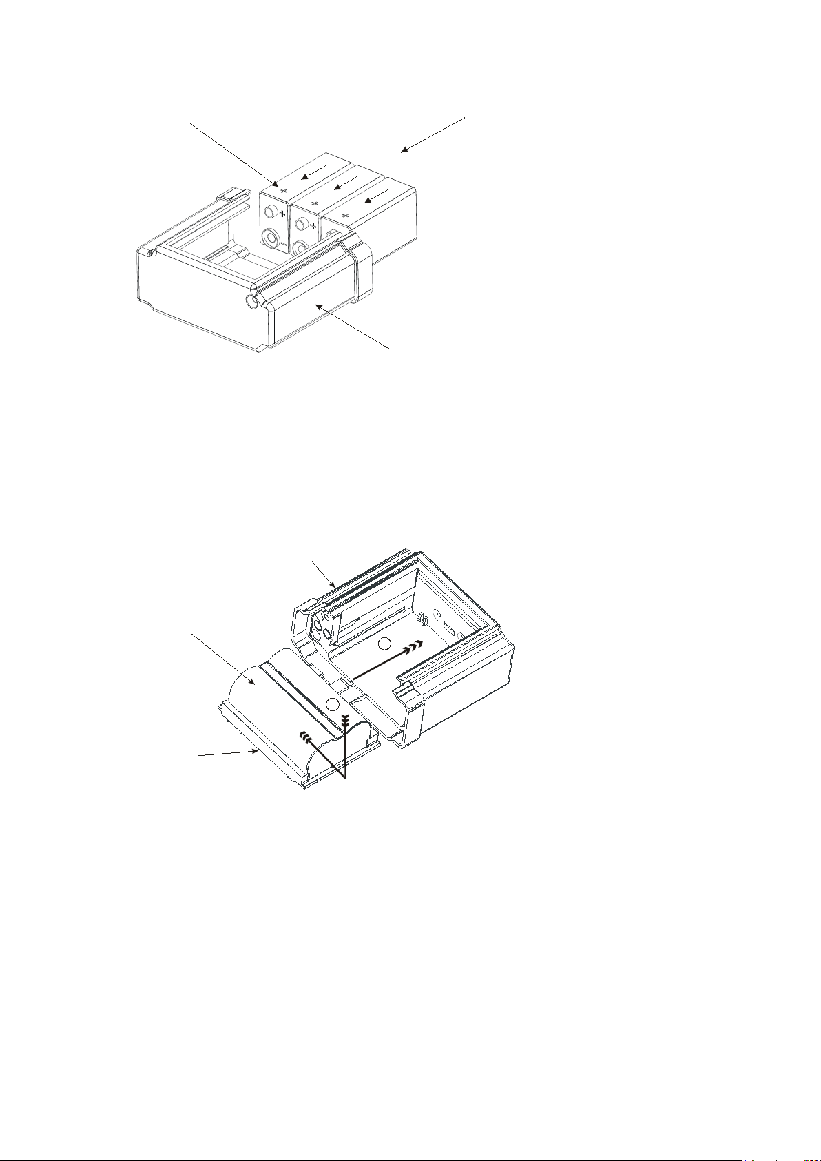
PP3 Battery
CAUTION: follow the following procedures for repla c ing and removing batteries.
Replacement:
Replace the batteries one at a time, m a king sure they are orientated correc tly and firmly seated
onto their terminals. Do not continue to push the battery if there is any misalign m e nt between
the mating termina ls . See Figure 24.
Removal:
If 1 or 2 batteries are fitted ensure that each is removed by carefully pushing sideways at the
base of each batter y until the terminals disengage at the fr ont. If 3 batteries are fitted, remove
the centre one fir s t b y carefully lifting it at its base until it disengages. Now remov e the remaining batteries as described abov e.
33
Page 34
Trackit Mk3 User Manual
Battery box PP3
PP3 Batteries
Polarity
+ve up
Battery Box Li
Battery Tray
Lithium battery
1
2
Figure 24 Removing and replacing P P 3 ba t teries
Lithium Rechargeable Battery
For the Lithium rec hargeable option, firstly slide out the tr a y that holds the battery inside the
box. Note that the T r a ckit Mk3 will continue recording for a couple of minutes, depending on the
number of channels, before shutting down. To slide out the Tray, push the battery gently towards the open en d of the Battery Box. Th is will slide out the battery and the Tray simulta neously. Now sepa r ate the battery from th e Tray by pushing it sidew a ys along the Tray to disengage the bayonet tabs.
Figure 25 Removing and replacing L ithium rechargeable battery
To fit a fresh ba tter y, either charge the original battery first or replace with a nother previously
charged battery. Fitting is a r everse of the removal process. Firstly slide the Batter y onto the
Tray to engage the bayonet fittings. Then slide the entire Tr a y plus battery assem bly back into
the Battery Box by engaging the Tray slides into the slots in the Battery Box. Note that there is
a tab on the Tray which engages into a slot in the ba c k of the Battery Box.
Special Lithium Battery Instructions for Use
• The battery pack is a Canon Type BP511 and uses rechargeable li th ium ion batteries. Always
refer to the documentation that ac companies the batter y for more information.
• The battery can only be charged outside the Trackit Mk3. Only the specific Canon charger for
the BP511 must be used. Lifelines do not su pp ly the charger; this is available from your local camera or video s tockist. Alway s r e fer to the documentation that accompanies the
charger for charging instructions.
34
Page 35
Trackit Mk3 User Manual
• Operating time will be shorter than usual at low temperatures. The battery can be used be-
tween 0 C and 40 C, but will give best performa nce between 10 C and 30 C.
• If the battery starts to give less operating times than usual, it has reached the end of its life
and must be replaced.
• The battery can be recharged at any time. However, since the battery will naturally dis-
charge itself over a p eriod of time, it is best to c harge the battery a d a y or two before planning to use it.
• Always attach the battery terminal c over when not in use . Do not allow any metal objects to
touch the battery ter m inals.
WARNINGS:
• Only use the Canon Type BP511 with the Trackit Mk3
• Keep the battery pac k away from fire
• D o not expose the battery pack to temperatures greater than 60°C
• D o not disassemble or modify the batter y pa ck
• D o not drop the battery pack or allow it to become wet
• Only use the specific Canon battery c ha rger for use with t he BP511 type ba tt ery
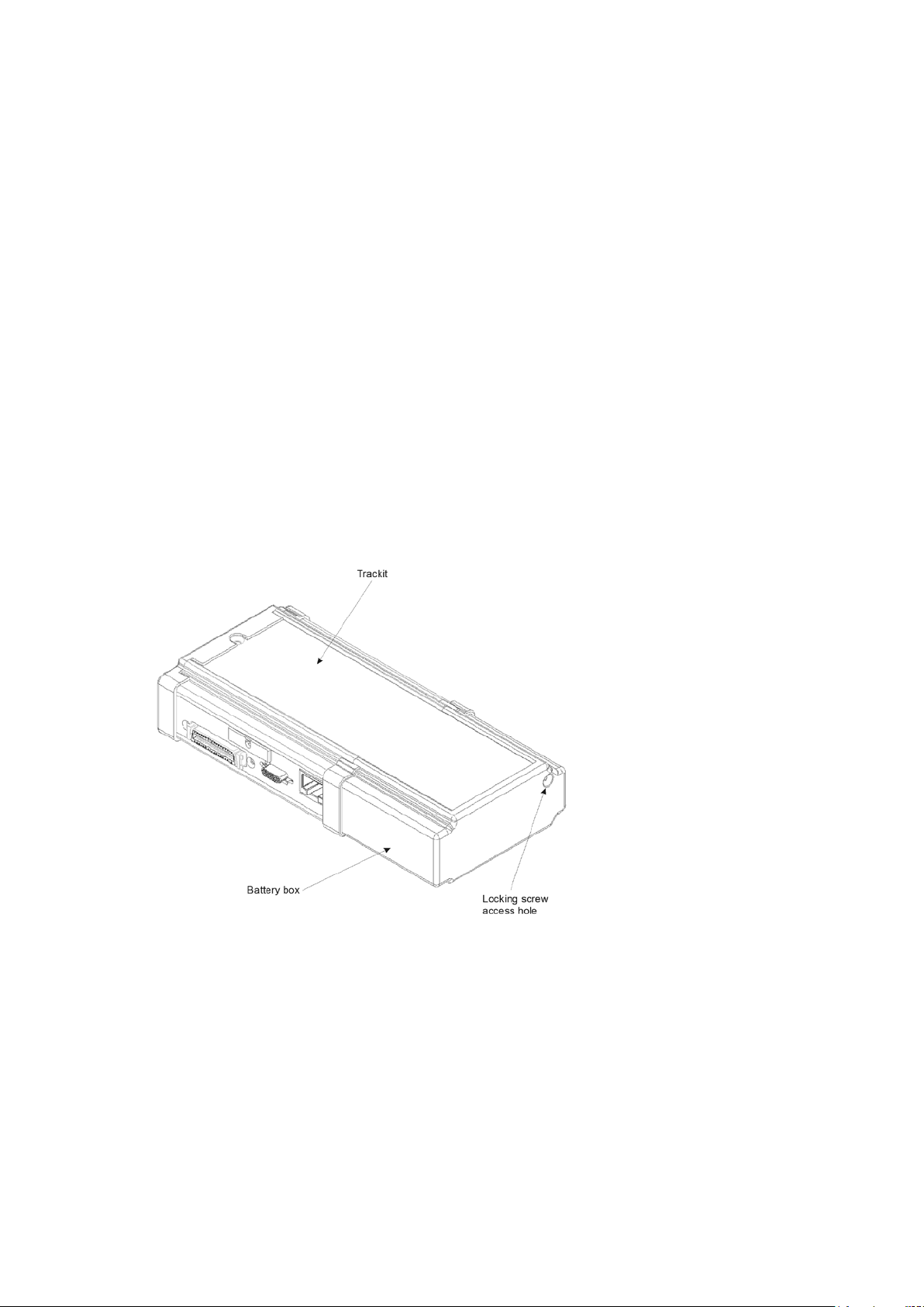
3 When the batteries have been replaced, and if the flash card does n ot n eed r eplacing, refit the
rear Battery box / door and screw it down with the special tool provided. The warning beeper will
stop.
CAUTION: do not over-tighten the locki ng screw – finger tight is all that is required.
Figure 26 Closin g t he rear Battery box /door
Changing the flash card
1 Open the Trackit Mk3 rear Battery box/door with the special tool provided. See Figure 23. The
unit’s warnin g b eep er will sound for a few seconds and the Door Op en symbol on the display will
flash.
2 Watch the yellow Light Emitting Dio d e (LED) indicating CF Card activity. When it is on, this
means the Trackit Mk3 is writing data to the PC Card.
CAUTION: do not remove the CF Card when the LED is lit.
35
Page 36
Trackit Mk3 User Manual
Card eject
button
Card access
LED
CF card
slot
Figure 27 Removing and replacing the flash card
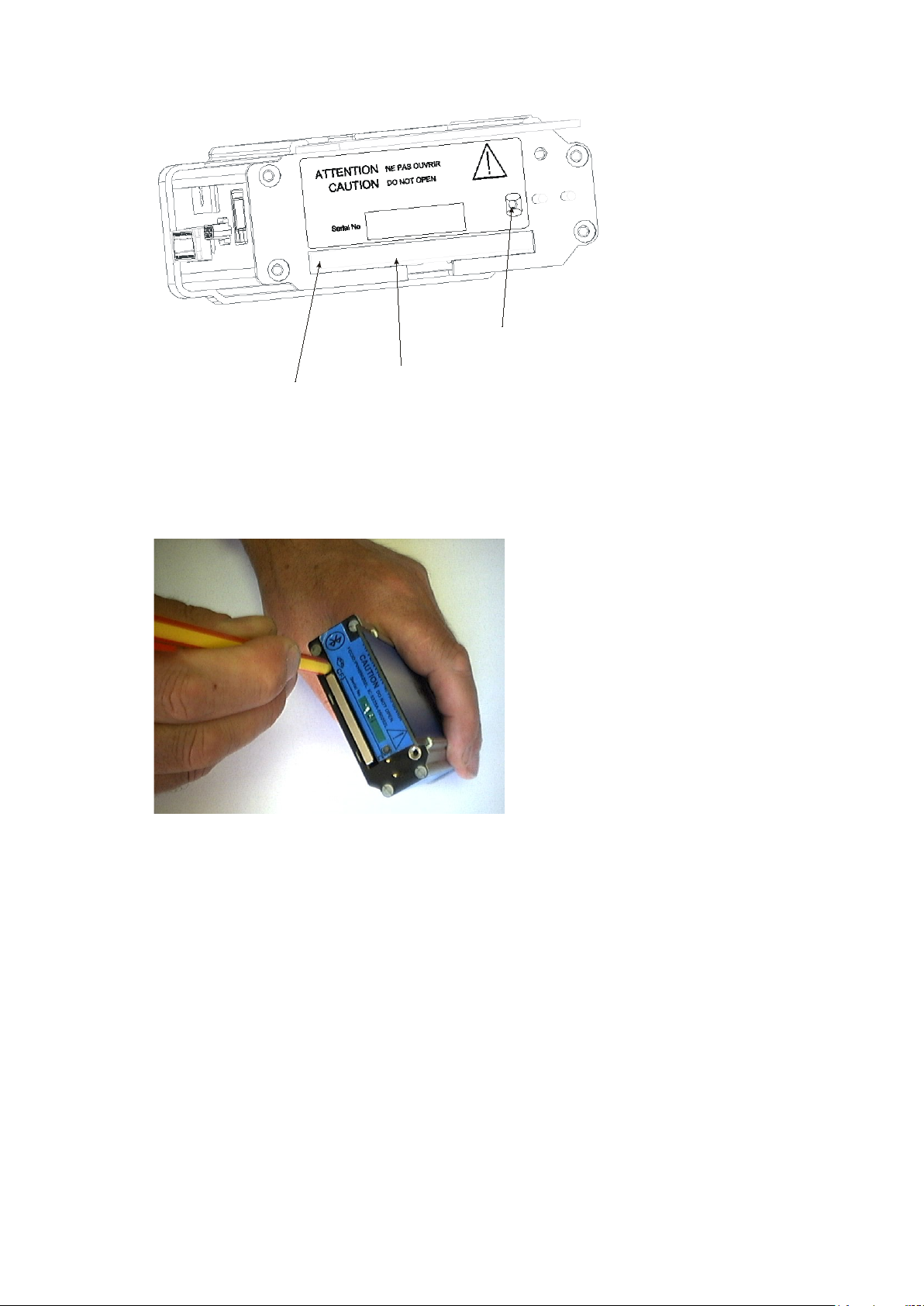
3 When the yellow LED is not lit, remove the card by carefully pressing the black eject button on
the left edge of the card slot with a plastic ball-point pen or similar. Keep the pen straight and
avoid pushing a t a n angle or inserting too far into the unit and causing damage.
Figure 28 Removing the flash card
CAUTION: Use only a plasti c ba ll-point pen or similar to eject the flash card. DO NOT
use the special Trackit Access Tool supplied wit h th e un it or any similar thin, pointed
object for this pu r pose, since it is possible to sli p a nd damage the insid e of the unit.
4 Replace the card with a blank one.
5 Refit the rear Battery box/door, and screw it down with the specia l to ol provided. See Figure 29.
CAUTION: do not over-tighten the locki ng screw – finger t ight is all that is required.
36
Page 37
Trackit Mk3 User Manual
5.2 Fitting the Clickon PCU
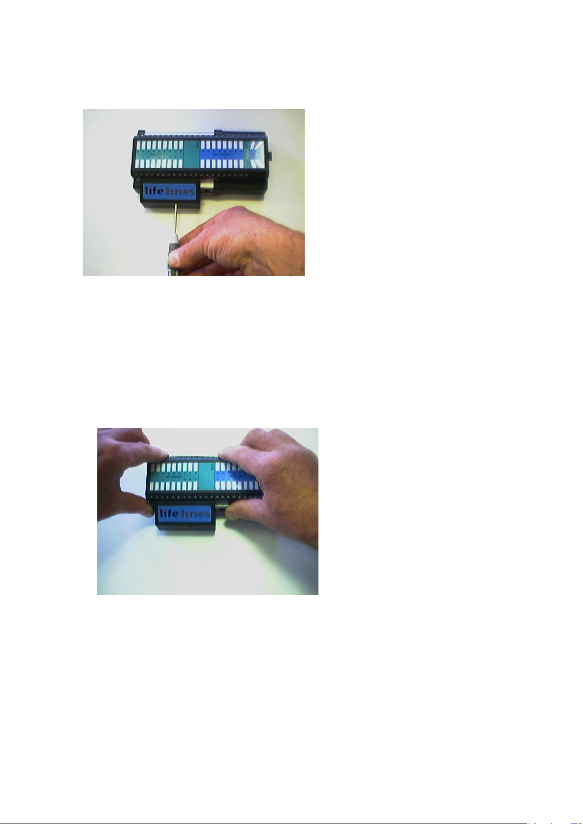
Retaining screw location
Figure 29 Clickon P CU Retaining screw location
1 Release the Clickon PCU by unscrewing the retaining screw as show n with the special tool
provided.
2 Lock by screwing up the retaining screw.
CAUTION: do not over-tighten the locki ng screw – finger t ight is all that is required.
Detaching the Clickon PCU
3 Ensure that the retaining screw is released as described above. Squeeze as shown below be-
tween fingers and thumb of ea c h hand until the PCU moves by about 5mm and unplugs
from the Trackit Mk3.
Figure 30 Detach the PCU
4 Lift the PCU a way from the Trackit Mk3.
37
Page 38
Trackit Mk3 User Manual
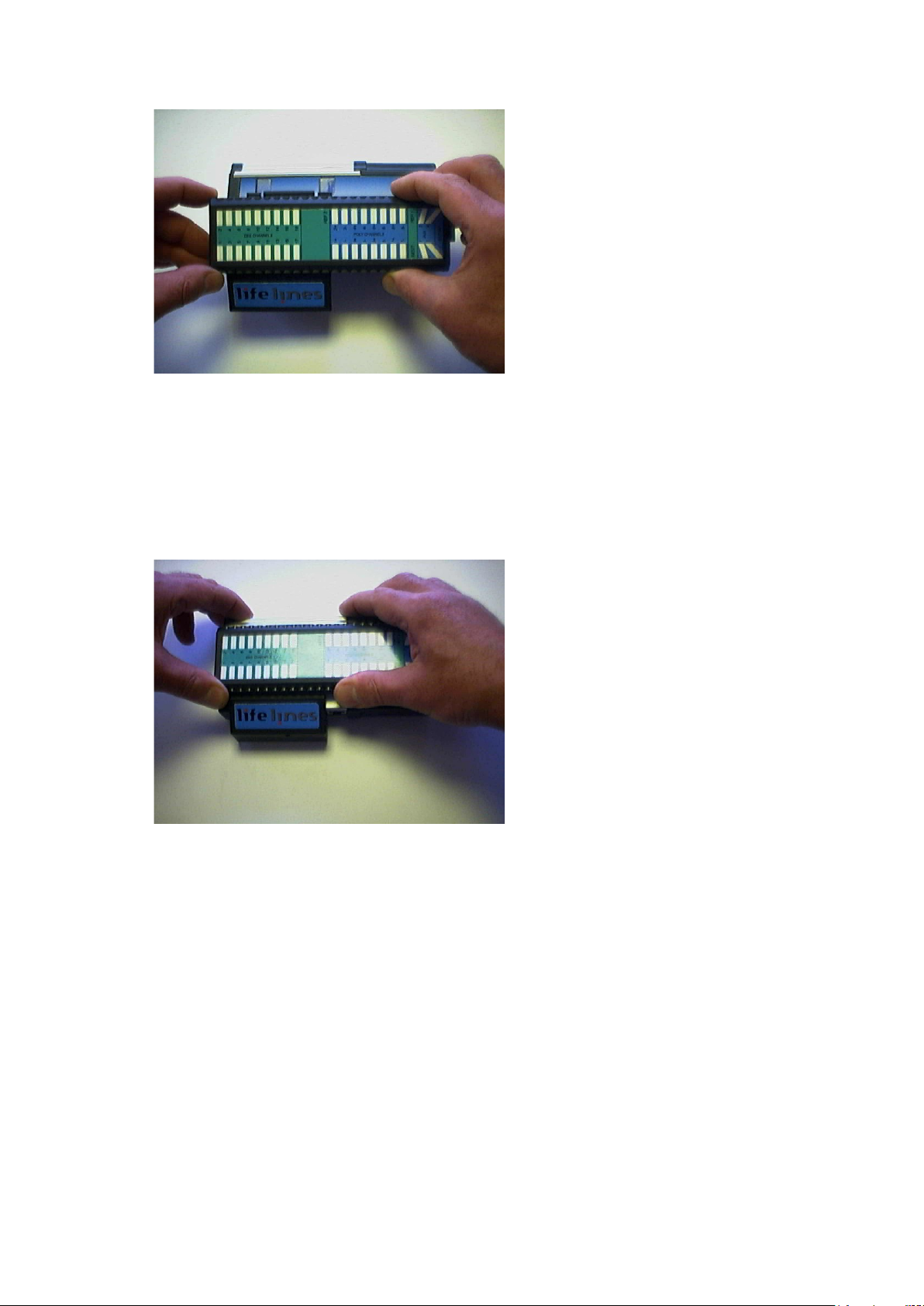
Figure 31 Lift the PCU away from the Trackit Mk3
Attaching the PCU
5 Position the PCU above the Trackit Mk3 as shown above in Figure 31 and lower it down en-
suring that the two tabs locate fully into the slots in the top of the Trackit Mk3.
6 Squeeze as shown below between fingers and thumb of each hand until the PCU locates fully
on the Trackit Mk3. Ma ke sure the two tabs of th e PCU are located correctly inside the slots
in the top of the Tra c kit Mk3. Lock the PCU with the retaining scr ew as described above.
Figure 32 Locating the PCU
5.3 Event marking
Once a recording has commenced, the button on the front pa nel of Trackit Mk3 acts as an event
marker. Events are stored in a n event file (filename.tev), from which on review the events are inserted into the displayed d a ta.
You can view events before r eplaying the recording using your EEG review program or the
Eventit.exe program that comes with the Trackit installation.
Trackit Mk3 can record 15 different event types. These can be seen by looking at the Tra c kit event
types in the online event viewer. See T r ackit Events, in S tep 9.
5.4 Ending a recording
To stop a recording:
1 Connect the Trackit Mk3 to the host softwa r e .
2 Click on the Stop Recording button in the Trackit control panel.
38
Page 39

Trackit Mk3 User Manual
Alternatively , to stop the Trackit Mk3 rec or din g in the field:
Either press the button on the front panel and hold it for approximately 5 seconds;
Or simply remove the card an d do not replace it. The idle time by default is only 5 minutes and can
be set in increments up to 255 minu tes – see Advanced Settings, below .
5.5 Identifying a recording
It is not possible to re c ord more than one tes t on a single card. This test is uniquely iden tified by
the Patient ID entered duri ng the setup procedure, and
by the user-definable file n a me.
5.6 Advanced Settings
There are two menus under the Trackit Con tr ol Panel:
Other Commands
Advanced Operations
Other Commands
Other Commands duplicates some of the controls on the Trac kit toolbar and recording control.
There are also miscellaneous controls for:
Set Trackit Time/Date: if the Trackit Mk3 is not recording, this manually sets the Trac kit’s time
and date to that of th e PC. Note: this fun c tion is normally done autom a tically when r e c or d ing is
started.
Get Trackit Set-up: this manually retrieves the setup from the Trackit’s memory and overwrites
the currently loaded setup on the PC. Note: this function is normally don e automatically whenever
the software detects a misma tch between the Trackit’s setu p a nd the PC setup.
Quiet On: if a host P C is connected, this tempor arily disables th e warning beep if the battery door
is opened while the Trackit Mk3 is turned on. It is automatically re-enable d a fter the PC is disconnected.
Quiet Off: if a host PC is connected, this re-en a bles the warning beep if the battery door is opened
while the Trackit Mk3 is turned on.
Advanced Operations
Advanced Operations contains entries, some password-protected, that change the way a Trackit
Mk3 records its data. These settings include:
Compensation for D C offsets
Adjusting the idle and recor d time
Enabling Auto start mode
etc.
To see the available option s under Advanced Operations:
1 Click on the Trackit Control Panel in the Trackit toolb ar.
2 Click on Advanced Operations.
3 Click on Settings.
Set Trackit Defaults
[> Advanced Operations > S ettin gs > Set trackit Defaults ]
Caution: please read the manual carefully before c ha nging or updating the Trackit Defaults. If you want to enable auto-start from flash card or append feature s, make sure all
the checkboxes in Trackit Defaults are checked.
39
Page 40
Trackit Mk3 User Manual
Trackit Defaults Tab 1
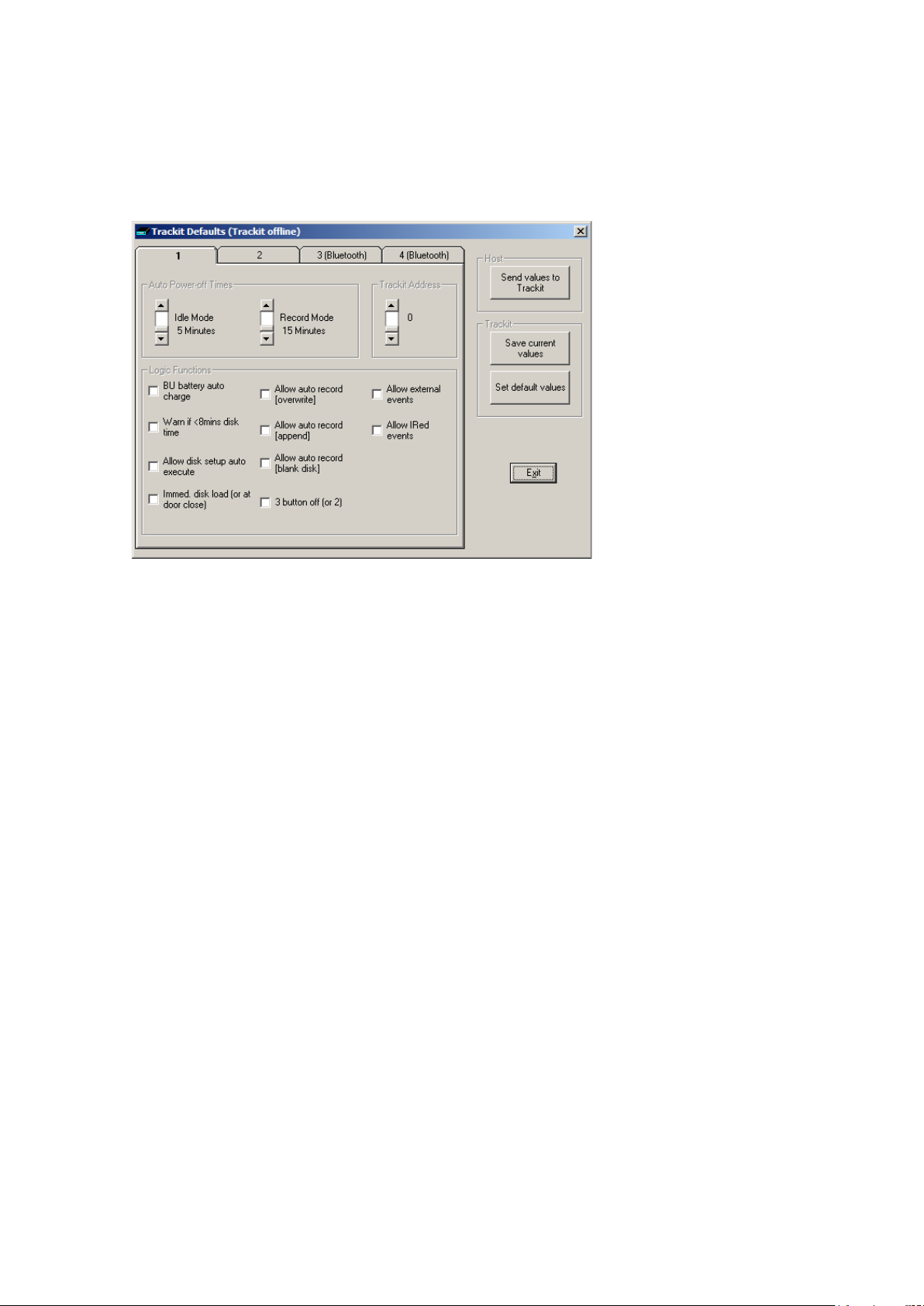
This menu item activates a control dia log that adjusts how the Trackit Mk3 behaves during a recording. See Figure 33.
Figure 33 Trackit Defaults Tab 1
To save new defaults to Trackit Mk3, press ‘Send these values to Trackit’, f ollo wed by ‘Save current
values’.
The following functions are supported:
Idle Mode: Trackit Mk3 turns itself off after a defined period when not recording.
Record Mode: Trackit Mk3 turns itself off after a defined period after having recorded. Trackit Mk3
waits for a defined period for a c a r d to be reinserted to append to an existing f ile which is <24
hours old. Other wise it starts a new recording on a blank ca rd. 60 minutes is enough for a user to
remove a card, re a d it a nd reinsert it to continue recording until the card is full.
Trackit Address: sets the serial address of the Trackit Mk3 if a simple serial network is configured
with several Trackits connected to on e P C.
BU battery auto char ge : enables fast-charging of the backup battery when the Trackit Mk3 is
connected to its ex te r nal power supply .
Warn if <8 mins card time: the Trackit Mk3 starts beeping when the card has room for only another 8 minutes of recordin g.
Allow card setup auto execute: allows a setup to be stored onto a flash card for a r ecording to
start automatically only when th e Trackit Mk3 is switched on. See Ways to start a recording, in
Step 8.
Allow auto record (overwrite): when this box is checked the Trackit Mk3 automatically overwrites any data on a card ins erted during a recording (e.g. when changing cards during a recording).
Allow auto record (a ppend): if a card is inserted with a file which has the same patient name
and is less than 24 hours old, Trackit Mk3 appends to rather than overwrites the data. This is a
very useful feature if a recording is interrupted, say for a quick r eview of the data. Trackit Mk3
waits in record mode, and when th e card is reinserted it car r ie s on recording to th e e xisting file on
the card.
40
Page 41
Trackit Mk3 User Manual
Allow auto record (blank card): check the box if you routinely w a nt recordings to take place
over several blank cards. This is a very useful feature if a recording over several days is required.
Allow external events: an external event marker can be attached to the Au x. port.
Allow IRed eve nt s: the optional Trackit infra-red even t ma r ker (Trackit Mk 1 only) can be used to
annotate a recordin g .
Immed. card load (or at door close): off by default, allowing the ca r d to b e loaded only when
the rear door is shut. Leave this box unchecked if you want to mak e rec or din gs over several cards
on a regular basis.
3 button Off (or 2): unchecked by default, allowing Trackit Mk3 to be turned off using only two
button presses (on/off button and down arrow button s im ultaneously). Trackit Mk 1 only.
All new Trackits have all the logic functions enabled by default except Immed. card load and 3 button Off. To update the logic functions in the Trackit Mk3 recorder when changes are made, click on
Send values to Trac kit, followed by Save current values. This saves the values in the Trackit
Mk3’s non-volatile memory. See Figure 33 above.
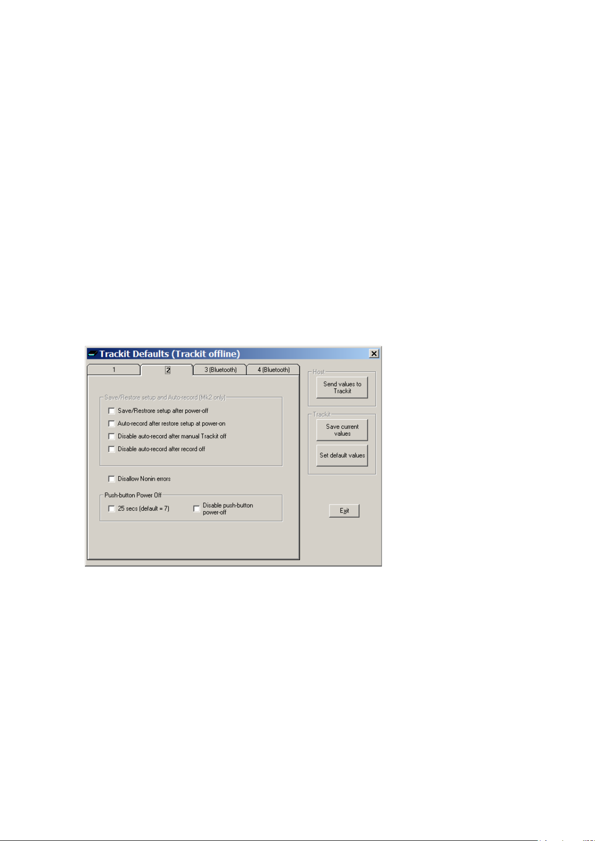
Trackit Defaults Tab 2 (Mk2 and Mk3 only)
The Trackit Mk2 and Mk3 have additional optional parameters. These are accessed via Tab 2 of
Trackit Defaults, as shown in Figure 34 below.
Figure 34 Trackit Defaults | Tab 2
Save/Restore setup and Auto-record
The Trackit Mk2 and Mk3 have much increased internal non-volatile memory. This memory a llows
it to save its entire Setup before powering-off. When next powered-on, it is able to restore its la st
saved Setup. This feature can significantly speed-up the download of a Setup to the Track it because the Host software automatically determines if the T rackit is already Setup correctly.
Another benefit to this save/recall of Setup is that the T r ackit can resume rec or d ing in exactly the
same state is was in the last time it was powered-off. This is especially useful if, during a recording, the User tak e s a long time to replace the batteries. To contr ol this feature, the following options are available:
41
Page 42

Trackit Mk3 User Manual
• Save/Restore setup after power-off. When checked, this enables the Trackit Mk3 to save its
entire Setup including Pati ent Name and Recording ID after power -off and recall it at power-on.
Note that the Patient Name and Recording ID are only retained f or 15 minutes after power-off
(refer below).
• Auto-record afte r r e st ore setup at powe r-on. When checked, this enables the Trackit Mk3
to continue recording if it was recording the last time is wa s powered-off, using the recalled
Setup and Patient Name an d R ec or din g ID, but only if it has been powered-off for 15 minutes
or less. If the Trackit Mk3 has been powered-off for lon ge r than 15 minutes, then the Patient
Name and Recording ID are overwritten with defaults (th e c urrent Setup remains)Note that the
parameter above must also be checked to used this feature.
• D isable auto-record after manual Trac kit off. When checked, this causes a potential Auto-
record situation to be cancelled whenever the Trackit Mk3 is powered-off either from its ow n
front-panel pushbutton or from the Host.
• D isable auto-record after record off . When checked, this causes a potential Auto-record sit-
uation to be cancelled whenever the Hosts instructs the Trackit Mk3 to stop recordin g.
Note that in all these Auto-record situations, the same rules apply to data storage on the flash card
as defined in the User Manual for the current Trackit Default Options | Tab 1. To summa r is e these
rules:
• The Trackit Mk3 will not record over a data file on the c a r d which is less than 24 hours old.
• The Trackit Mk3 will append new data, if enabled, if the d a ta file on the flash card is less than
24 hours old and the Trackit Mk3’s Setup and Patient Name and Recording ID are identical to
that on the card.
• The Trackit Mk3 will overwrite data on the flash card, if enabled, if the data on the card is m or e
than 24 hours old.
• The Trackit Mk3 will write new data to a blank flash card, if en a bled.
Disallow Nonin Errors
This is a feature a vailable to all Track its running firmware Vx.13.x or later. N or mally, the SaO2
data stored to the flash card is set to an invalid value (127) to m a r k any of the followin g Nonin errors:
1. Sensor disconnected
2. Out of track
3. Low perfusion
4. Marginal perfusion
5. Bad pulse
Errors 1 and 2 are serious and do cause invalid data. However, short-term errors 3 to 5 are not so
serious and the N onin device is still ab le to produce meaningful data. The av a ilable option is as follows:
• Disallow Nonin Errors. When checked, all errors 1 – 5 produce inva lid data ( 127) . W hen
unchecked, it is only errors 1 a nd 2 which cause the data to be marked as inv a lid, otherwise the Nonin da ta is unmodified.
Get Card Info
[> Advanced Operations > S ettin gs > Get Card Info]
Selecting Get Ca r d Info opens a dialog showing the current s ta tus of the flash card, including the
file name and any error codes (‘Disk OK’ is displayed to indicate a properly functionin g card).
Should any problem occur with the fla s h card, copy and paste th is dialog and send it to y our Lifelines distributor.
To format a flash card:
42
Page 43

Trackit Mk3 User Manual
1 Insert the flash card into the Trackit Mk3 and connect to the h ost computer. See Step 6 Connect
Trackit for Setup.
2 Open the Get Card Info dialog box.
3 Choose Format Disk from the Disk Utilities Menu.
4 Click on the Format button.
5 Wait for the format complete message to appear. A 1GB c a r d will tak e a r ou nd 5 seconds to for-
mat, larger cards will take longer to format.
Caution: in normal operation, fl a sh c a rds rarely require formatting. I f formatting is done
on the PC it is easy to inadvertently create the wrong card form a t.
Earlier Trackits with V4.19 firmware and earli er use FAT16 cards only (re ferred to in
Windows as ‘FAT’). If for any reason y ou wish to format a fla sh c a rd, make absolu t e ly
certain you know wha t you are doing! It is easy to convert from FAT16 to FAT32, but
very difficult t o c onv ert the other way (the c a rd has to be manual ly re-partioned and r e formatted). In the rare circumstances that it is necessary to format a flash card, use the
inbuilt Trackit format utility.
Later Trackits fitted with firmware V4.21 and later use F AT 16 or F AT32 cards and there
are format facilities in the Trackit to support both types.
Factory Settings
[> Advanced Oper a tions > Settings > Fa c tor y Settings]
Factory settings a r e protected by a pass word (via Other Option s in the View Menu). O nly trained
support staff should have access to factory settings.
Factory settings a lso allow you to comp ensate for any DC offsets that may be present on any of the
recording inputs and save the values in the Trackit’s non-volatile memory.
Configuration
[> Advanced Operations > S ettin gs > Configuration]
Configuration gives acc es s to th e opt ional pulse Oximeter and the independent sample rate and
headbox mode features. The code displayed c a n be copied and emailed to L ifelines for an a c tivation
code to be sent back.
5.7 Reading an ambulatory recording
Click the ‘Open a ll playback files’ bu tton on the left hand side of the Trackit softw are toolbar (refer
to Figure 14 on page 25) to playback a recording.
It is possible to lau nch a second instan ce of the Trackit softw are and view an on-going ‘Record to
PC’ file. If th e on-going file is located in a s hared folder it is pos s ible to view the file a c r oss a local
network.
As an alternative to the Trackit software which offers basic playback features, any EDF-compatible
viewer can be used to read the s tandard EDF files recorded by the Trackit Mk3.
All Trackit record ings have a user-definable 8-character file name. They are stored in EDF format,
readable in all EDF-compatible EEG browsers. In an EDF-compatible browser, the pa tient’s name
and recording ID are displa yed in the test properties.
Lifelines currently recommends:
Nihon Kohden 1100 and 1200 EEG
Neurotronics Polysmith Sleep softw are
Nicolet One EEG
Natus Coherance EEG (formerly Deltamed/Itmed)
Persyst Insight EEG
43
Page 44

Trackit Mk3 User Manual
Input bias current
< ±25nA
<3.5µV pk–pk @ 0.16Hz to 70Hz
Input bias current
< ±25nA
Appendix 1: Trackit Mk3 Specifications
Note: Lifelines reserves the right to chan ge product specifications a t any time without notice. This
is in-line with the company’s policy of continual produc t development.
EEG inputs
Number of EEG channels 24 monopolar touchproof inputs
ADC Resolution 16 bits
Sampling 1 to 256Hz or 25 to 200Hz rate, simultaneous sampling all
channels
Differential input impedance >20 Mohms
Common mode input im p edance >100 Mohms
Common mode rejec tion ratio >100dB @ 0.16Hz to 70Hz with ac tive ground connected
Equivalent input noise
Hardware gain 500 ±2%
Max differen tia l AC input
before clipping
Max operational DC input voltage
(electrode offset)
Bandwidth 0.16Hz to 70Hz (–6dB)
Max common mode input voltage 2V pk–pk
<3.5µV pk–pk @ 0.16Hz to 70Hz
10mV pk–pk
±500mV
Polygraphy inputs
Number of polygraphy inputs 8 bipolar touchproof inputs
ADC Resolution 16 bits
Sampling 1 to 256Hz or 25 to 200Hz rate, simultaneous sampling all
channels
Differential input impedance >20 Mohms
Common mode input im p edance >100 Mohms
Common Mode Rejection Ratio >100dB @ 0.16Hz–70Hz with activ e gr ound connected
Equivalent input noise
Hardware gain, AC setting 500 ±2%
Max differen tia l AC input before
clipping
Max operational DC input voltage
(electrode offset) , AC setting
Hardware gain, DC setting 10.1 ±2%
Max differen tia l input before clip-
ping, DC setting
Bandwidth 0.16Hz to 70Hz (–6dB) or DC to 70Hz
Max common mode input voltage 2V pk–pk
10mV pk–pk
±500mV
±250mV
44
Page 45

Trackit Mk3 User Manual
Bandwidth
DC to 70Hz (–6dB)
Calibration
0.5mV p–p square wave @ 1Hz at ADC input. Amplitude acc uracy ±5%.
Patient Event
Size
16cm x 8cm x 3.5cm
Aux. high-level DC Inputs
Number of Aux channels 4 on Aux. connector
ADC Resolution 16 bits
Sampling
Input impedance 47 Kohms
Hardware gain 1 ±2%
Max input before clipping ±2.5 V
1 to 256Hz or 25 to 200Hz rate, simultaneous sampling all
channels
Modes of operation
Impedance
< 2 to > 90 KOhm, measured with 0.075u A p–p, 5Hz signal. Measuremen t
accuracy ±15%.
Connections, ports and controls
Patient Connection Unit
(36 pin MDR connector)
Front-panel push-buttons 1 on/off push-button Patient Event during record
Aux. Connector 1
(RJ45 connector)
Aux. Connector 2
(15 pin Micro-D connector )
CF card port 1 TypeII socket (3.3V)
Batteries 3 type P P3/MN1604
Internal beeper sounds w hen:
Connector for touch-proof Patient C onnection Unit (PCU ), either Leaded or Clickon
USB port (isolated from patient)
External Patient Event input
Bluetooth Modu le I/O
Nonin XPOD SaO2 probe input
4 Aux. High-level DC inputs
1 type BP511 Lithium rechargeable
door open
battery low
card storage low
Back-light display
Current Time and Date
Recording Time
Battery Life rema ining
Disk Storage remaining
Door open warning
Recording format
Native European Data Format (EDF)
Native MSDOS/Windows card data structure
Physical characteristics
Weight 500g including card and 3 PP3 batteries
450g including card and Li rech a r gea ble battery
45
Page 46

Trackit Mk3 User Manual
EN60601-2-26
quirements and EEG systems.
ments.
M90
quirements.
ments, calling:
EN55011
Conducted Emissions, Group 1, Class B
EN55011
Radiated Emissions, Group 1, Class B
EN61000-4-2
Electrostatic D ischarges
EN61000-4-3
Immunity - Radiated RF Field
EN61000-4-4
Immunity - Transients Bursts
EN61000-4-5
Immunity – Surges
EN61000-4-6
Immunity – Conducted
EN61000-4-8
Immunity – Power frequency fields
EN61000-4-11
Immunity – Voltage dips, interruptions
EN61000-3-2
Harmonic Emissions
EN61000-3-3
Voltage Fluctuations/flicker
with oxygen or nitrous oxide
Safety and EMC standards
EN60601-1 and
UL60601-1:2003 USA standard for medical electrical equipment, gener a l require-
European standard for m edical elec tr ic al equipment, general re-
CAN/CSA 22.2 No 601.1
EN60601-1-2:2001 European standard for m edical elec tr ic al equipment, EMC require-
Degree of protec tion against electr ic al shock
(when connected to host system)
Type of protection against electrical s hock
(when connected to host system)
Degree of protection against harmful ingress
of water
Mode of operation Continuous
Degree of safety of application in the presence
of a flammable an aesthetic mixture with air or
Canadian standard for medical electrical equipment, general re-
Type BF
Internally powered
or mains powered Class 1 or 2
or USB
Ordinary (no protection)
Not suitable
46
Page 47
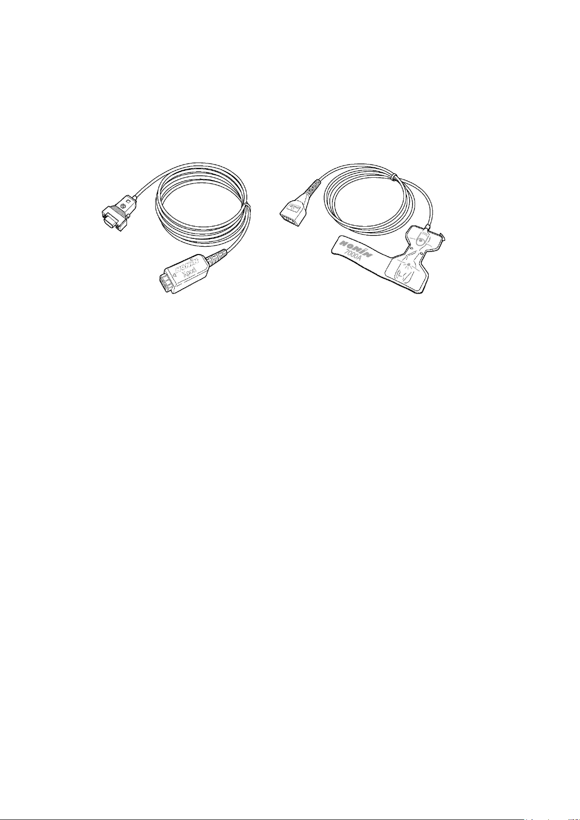
Trackit Mk3 User Manual
Description
XPOD pulse oximeter
with optional AUX Input Box.
Part Number
1022 or enhanced 1119 (Plethysmograhic data for Trackit Mk2 only)
Appendix 2: Trackit Mk3 options
Nonin XPOD pulse oximeter
The Nonin XPOD is an in-line pulse oximeter that con nects to the second seria l port on the side of
the Trackit Mk3, or the optional AUX input box. Finger probes may be purchased locally from
Nonin.
XPOD pulse oximeter:
available from Lif elines Ltd
Figure 35 Pulse oximeter and oximet er probe
Trackit Mk3 takes the digital output from the XPOD, an d displays it as a DC-analogue s ig nal, along
with a real-time numeric display of O
range 0–100%.
Additionally, for the Trackit Mk 2 and 3 only, an enhanced XPOD will be available that of fers Plethysmographic pulse data.
Note that the XPOD oximeter and Probe ta ke power from the Trackit Mk3 and the typical recording
time will be reduced by approx ima tely 22%. The later version of the XPOD which is coloured blue
instead of grey, is lower-power and only r educes the recording time by approxima tely 13%.
saturation an d p ulse rate. The data s tor e d is displayed in the
2
Oximeter probe:
available from Nonin
Ideal applications
The XPOD pulse oximeter can be used extensively in sleep studies while monitoring patients w ho
suffer from sleep apnoea. T he pulse oximeter is used to corre late the correspon d ing dip in the
blood’s O
Pulse oximetry is also used in a wide va riety of applications such as hypoxia in children with central
breathing disorders, hypoxic events during epileptic seizures, etc.
saturation with an apnoea attack.
2
Ordering information
Requires Version 2. 1.x EPROMS, and will w or k with all Trackit v ariants. Will also wor k
Operation
To enable the pulse oximeter:
1 Open the Trackit Control Panel.
2 Click on Advanced Operations.
3 Choose Configuration from the Settings Menu.
4 Copy the code displayed in the configuration dialog an d em ail it to your nearest Lifelines distrib-
utor.
5 You will receive by return an unlock code that will enable this feature.
47
Page 48
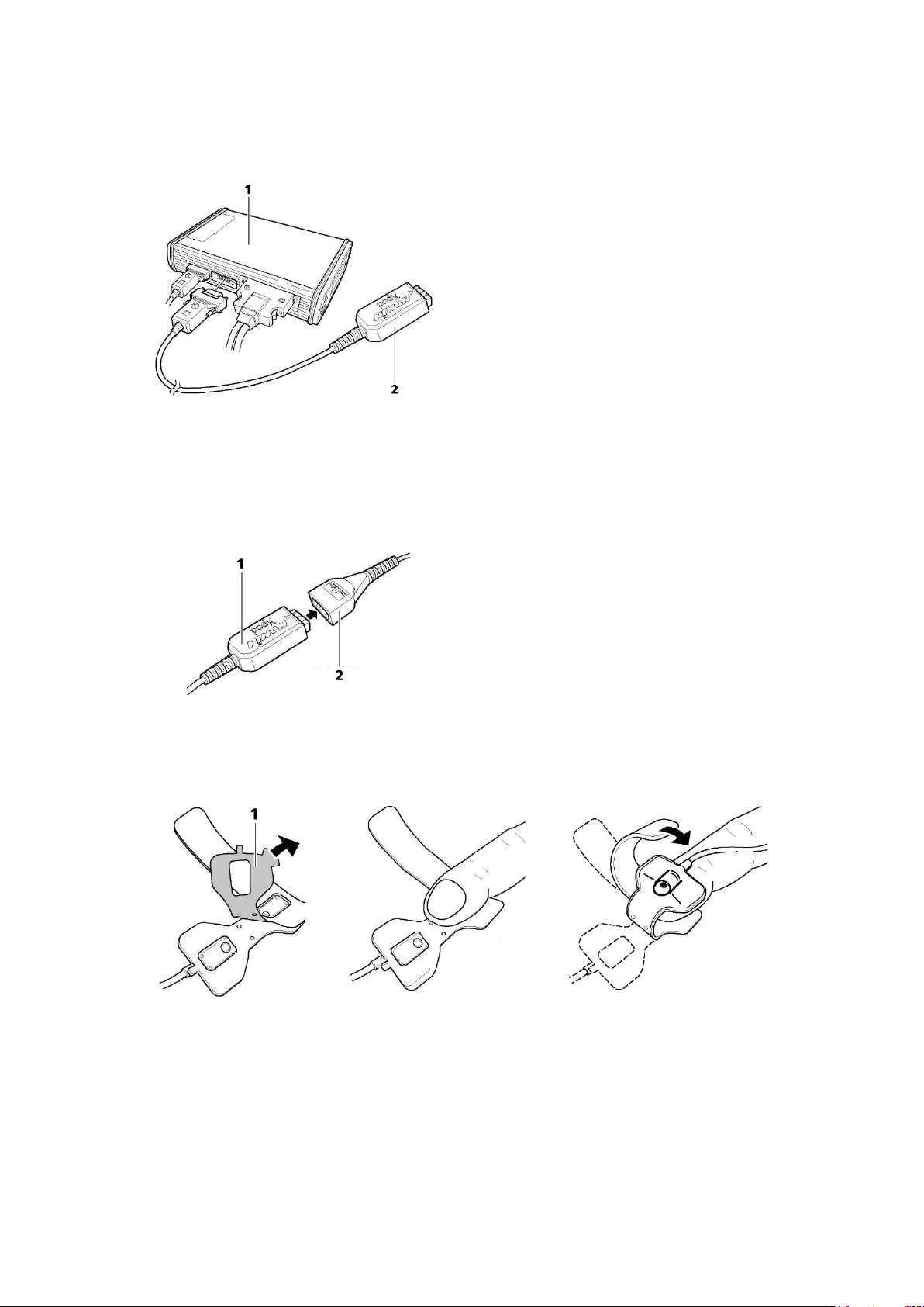
Trackit Mk3 User Manual
Setup as follows:
1 Connect the pulse oximeter (see Figure 36) to the second 15-pin serial connector (AUX con-
nector) on the side of the Trackit Mk3.
1 Trackit recorder
2 Nonin XPOD pulse oximeter
Connecting to the Tr a c kit recorder
Figure 36 Connecting the oxime te r to Trackit Mk3
2 Connect the oximeter probe, which can be purchas ed from N onin via their local distributors –
http://www.nonin.com/sensors.html.
1 Nonin XPOD ox im ete r
2 Nonin 7000A oximeter probe
Figure 37 Connecting the oximet er to the oximeter probe
3 Remove the paper backing from the oximeter probe (see 1 in Figure 38). Attach th e pr ob e to
the index finger of the patient’s non -d om inant hand, as show n be low.
Figure 38 Attach ing the oximeter probe to the finger
4 Include the SaO
signal in the amplifier s etup using one of the AUX inputs and create a record-
2
ing channel as per normal.
5 Connect the Trackit Mk3 to the host PC. Switch on, and clic k on Connect in the Tra ckit Control
Panel.
6 Observe the display of SaO
and pulse rate on the Trackit Control Panel. Probe off, an d XP O D
2
disconnect information is displayed.
48
Page 49
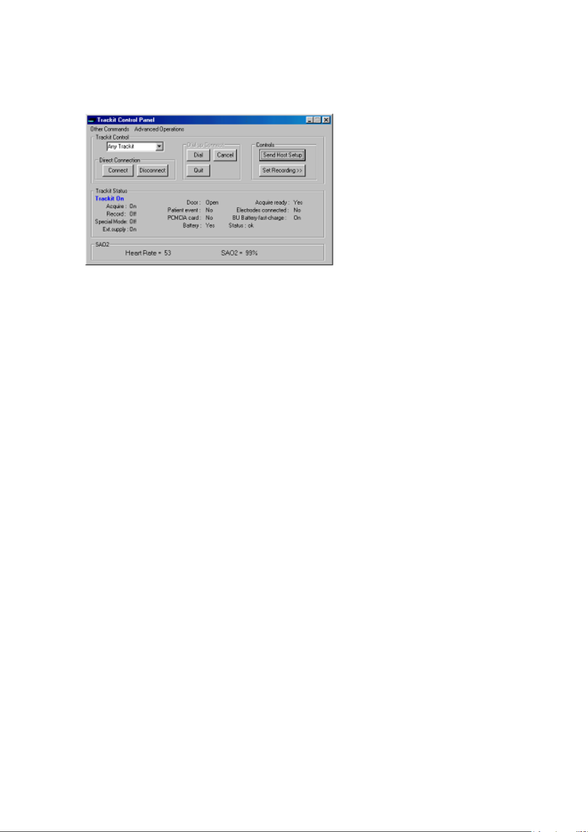
Trackit Mk3 User Manual
7 Start the recording. SaO
8 To display O
Saturation va lues on the trace displa y, under the channel label, click the SaO2
2
is stored as an analogue DC signal with a scale 0-100%.
2
channel label, and put a checkmark by Numeric.
Figure 39 Display of SaO2
49
Page 50
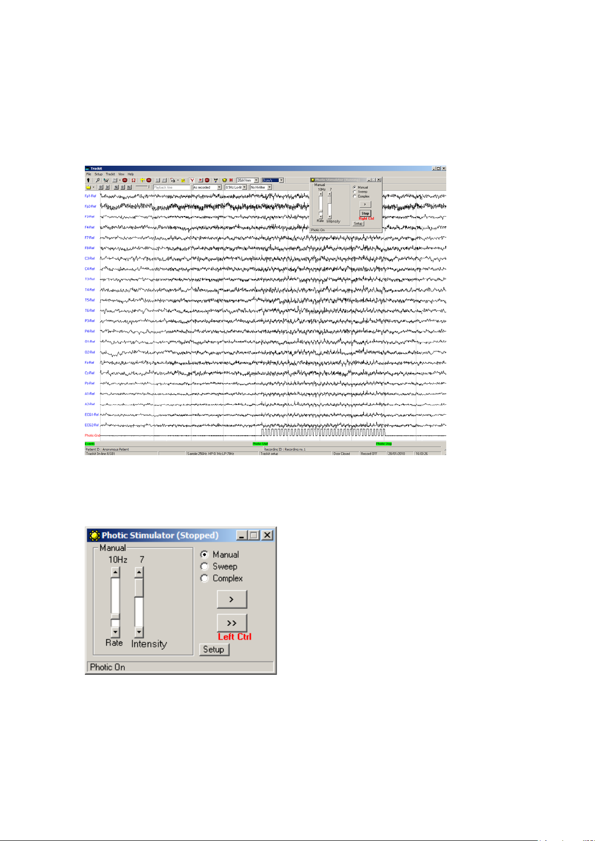
Trackit Mk3 User Manual
Appendix 3: Photic Stimulator and Hyperventilation
Photic Stimulation
An optional Lifelines Photic Stimu lator is available which can be used with the Trackit Mk3 to asses
patient photosensitivity in EEG studies. For a detailed d es cription of operation, connection an d
specifications please refer to the separate documentation “Lifelines Photic User Manual”.
Figure 40 Photic Stimulation
Click on the Ph otic Stimulation icon in the top toolbar to bring up the Photic Stimula tion control
panel, shown below.
Figure 41 Photic Stimulation contr ol window
This window allows single, manual, sweep and complex seq uences of Photic sti m ulation to be produced. Photic start/stop ev ents are recorded as shown abov e. By us ing the Trigger output from the
Photic Stimulator a nd connecting to an Aux input on the Trackit Mk3, the actual Photic f lash ‘ticks’
are produced in the recordin g.
50
Page 51
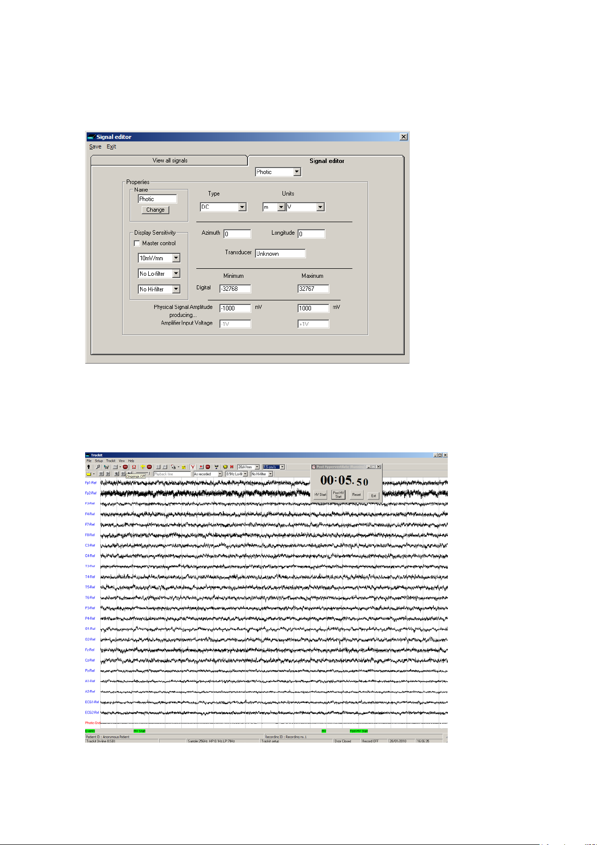
Trackit Mk3 User Manual
Note: to setup a suitable Photic trigger signal definition open the Signal libra r y as described in section 4.1, and define a s ig na l with a name “Photic”, set it to type DC, units mV an d Physical Signal
Amplitude of +- 1000mV/V . Set the sensitivity to non-master and 10mV/mm.
Figure 42 Photic trigger signal definition
Hyperventilation
A method of timing and marking a Hyperventilation and post-Hyperventilation activation sequ ence
is provided.
Figure 43 Hyperventilation
51
Page 52
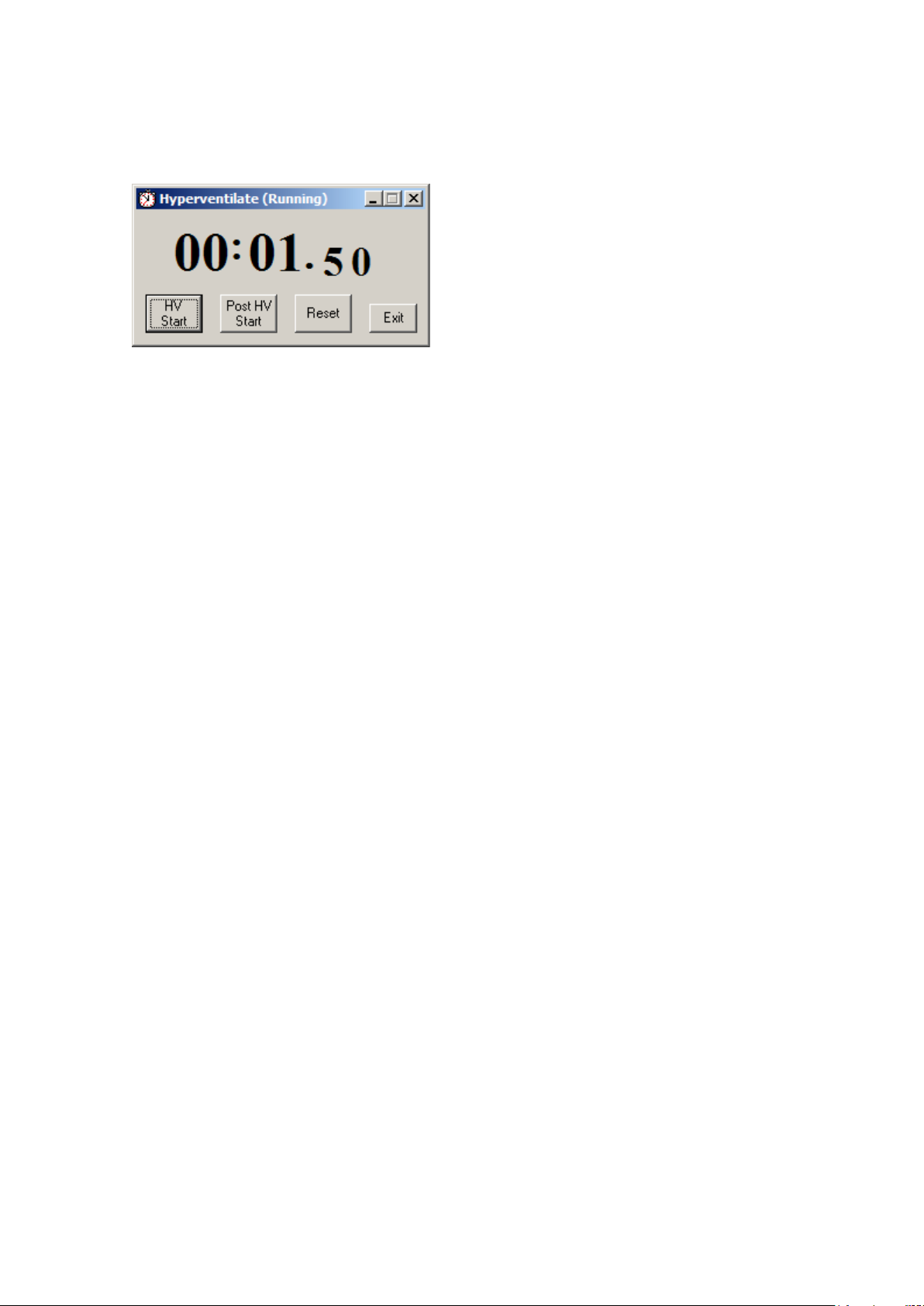
Trackit Mk3 User Manual
Click on the Hyperventilation icon on the top toolbar to br ing up the control window as shown below.
Figure 44 Hyperv entilation contr ol window
This provides a digital timer, which is used as follows:
• Click on HV Start to s tart the HV period and the timer starts running. An ‘HV Start’ event is
recorded.
• Thereafter an ‘HV’ event is automatica lly generated every 10 secon ds .
• Click on Post HV Sta r t to start the post HV per iod. A ‘Post HV Start’ event is recorded.
• Thereafter a ‘Post HV’ event is automatically generated every 10 seconds.
• Click on Reset or E xit to end the hyperv entilate activation.
Note that the Post HV Start will not work unless HV is in progres s . Likewise, HV Start will not work
if Post HV is in progress.
52
Page 53
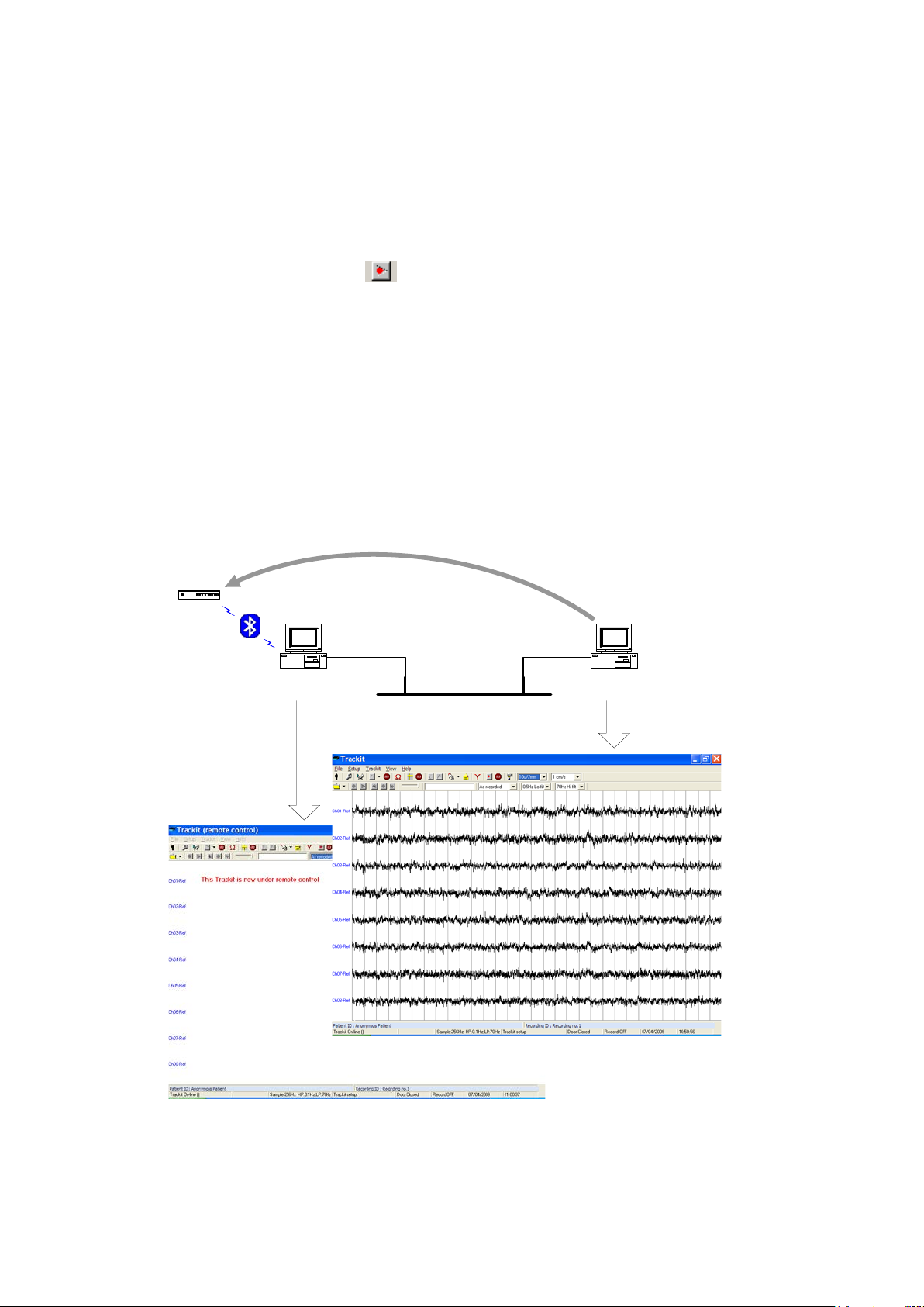
Trackit Mk3 User Manual
Trackit
Ethernet
Trackit software
running as client
Trackit software
running as server
Remote control
Appendix 4: Record to PC and Synchronised Video
1 Record to PC
This facility enables EEG data from the Trackit Mk3 to be recorded directly to the PC. Headbox
mode must be enable d in Advanced Opera tions in the Trackit Control Panel.
1. Connect to the Trackit Mk3 and setup in the norm a l wa y. Connection can be either USB, or
Bluetooth.
2. Click the Record to PC button
3. Specify a storage location on the PC for the EEG data file.
4. Enable, if desired, ‘Trackit auto-record when host comms los t’. The Trackit Mk3 will automat-
ically commence re c ording to its own CF card when the communication link is lost. This can
be particularly useful when a Blue tooth link is being used.
2 Network Connection
There follows an explanation of how to remotely connect to th e Trackit Mk3 and acquire data over
a TCP network.
Overview
The diagram below shows how the system w or ks. The Trackit applicat ion runs on the server PC
which is connec ted via serial or Bluetooth to a Trackit Mk3 device. A r emote client PC which is also
running the Trackit applica tion opens a TCP con nection to the server w hich enables the client to
take over control of the Trackit Mk3.
The server PC can be located locally to the patient, in the bedroom for example, and a wireless
Bluetooth link c onfigured to provide untethered communication with the Trackit. After any initial
setting up on the server, local c on tr ol can be relinquished and su bs equently acquired by a client
anywhere on th e network. In this scenario the server computer could be one of the miniature PC
53
Page 54
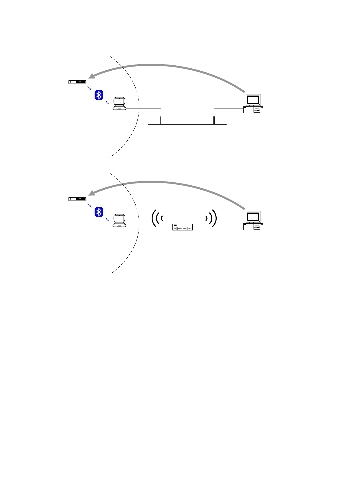
Trackit Mk3 User Manual
Trackit
Ethernet
Trackit software
running as client
Trackit software
running as server
Remote control
Patient
environment
Notebook or
tablet PC
Trackit
Trackit software
running as client
Trackit software
running as server
Remote control
Patient
environment
Notebook or
tablet PC
WLAN Router or
Access Point
platforms such as a notebook or a tablet which could be easily a ccommodated with in the patient
environment, a s shown below.
The Ethernet c onnection shown above can be replaced with W LAN technology, which connects the
server and client as shown below.
Note that in all these s cenarios Trackit Video can be recorded on the client PC but on ly from a local
camera connec ted dir e ctly to the client PC.
54
Page 55
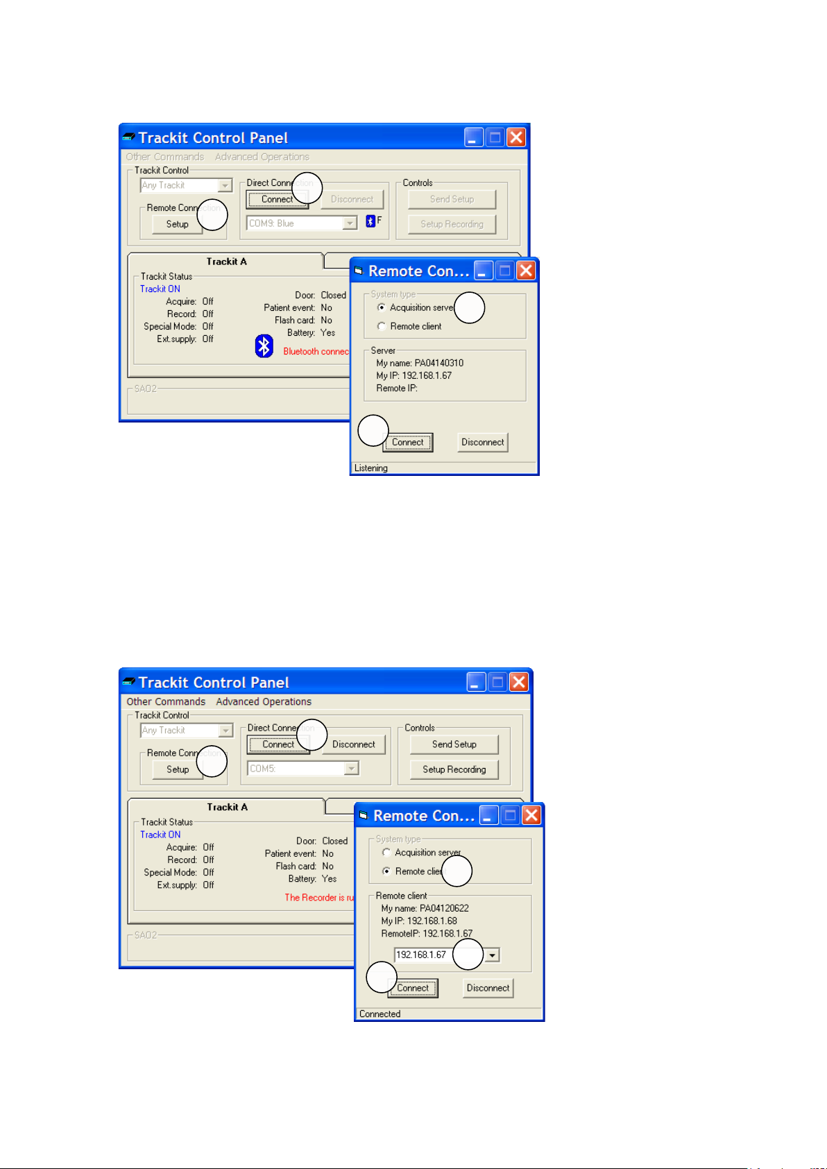
Server Set-up
Trackit Mk3 User Manual
1. In the normal way, con nect to the Trackit device via either serial con n ection or Blu etoo th.
See Trackit Con tr ol Panel above.
2. Click the Remote Connec tion Setup button to dis play the Remote Connection window a s
shown above.
3. Select Acquisition Ser ver.
4. Click the Connect Button. Make a note of the ‘M y IP’ address which will be required by the
client.
5. The program will now listen for a connection from a remote client.
Client Set-up
1. Click the Remote Connec tion Setup button to dis play the Remote Connection window a s
shown above.
55
Page 56
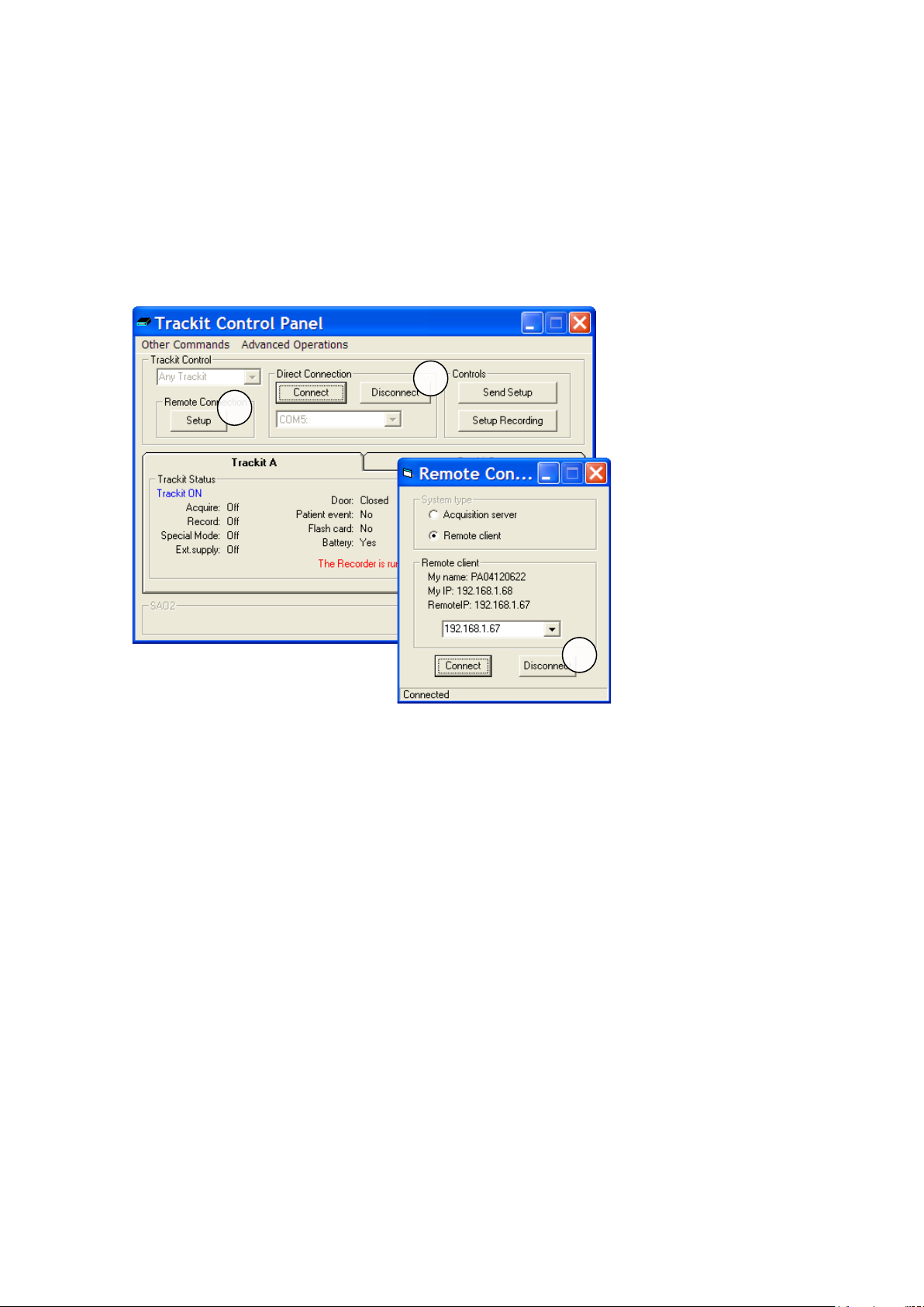
Trackit Mk3 User Manual
2. Select Remote Client.
3. Enter the IP address of the server as sh ow n in the previous section.
4. Click the Connect bu tton and leave the Remote Connection window open.
5. Click the Connect bu tton in Control Panel.
At this point the cli e nt will have complete control over the remote Trackit just as if it were connected locally.
The server will dis p la y ‘This Track it is now under remote control’ to indicate that c ontrol has been
transferred to th e client.
Client Shut-down
1. Click Disconnect in the Control Panel.
2. Click the Remote Connection Setup button to display the Remote Connection window as
shown above.
3. Click Disconnect.
56
Page 57
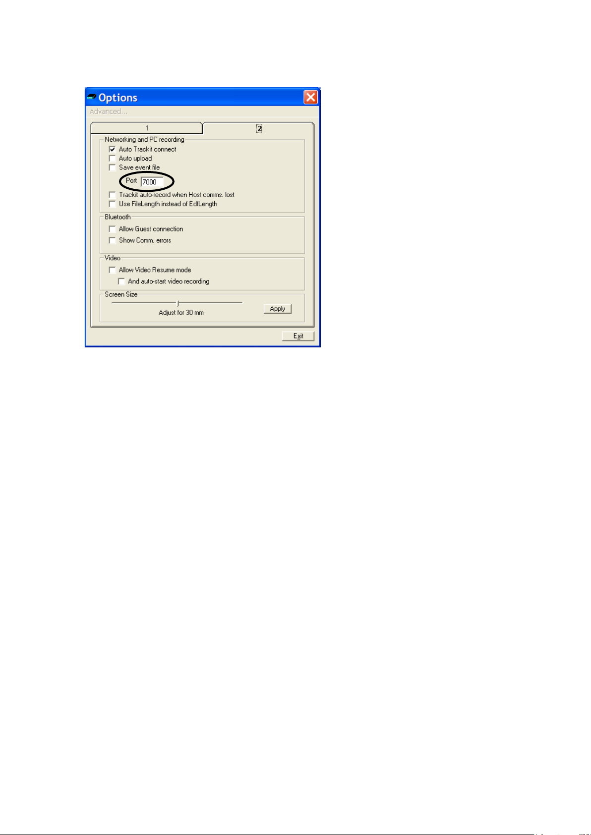
Selecting IP Port
Trackit Mk3 User Manual
In order for the c lient and server to open a c om m unication channel it is important tha t they both
use the same port. This is set up in the Tra ckit application View|Other Options|Ta b 2 a s shown
above.
Do not use the range 0 through 1023 w hich are pre-allocated for special purposes in the TCP/IP
protocol.
3 Video
Overview
Trackit Video prov ides an unobtrusive solution for the a m b ulatory monitoring of EEG with time syn chronised video. The Trackit Mk3 provides tim e s ync information to the video file to ens ure accuracy down to the near est frame: essential to c or relate behaviou ral and physiologic al information.
Modes of operatio n
• Synchronized video acquisition and recording
• EEG recorded on the Trackit Mk3 with time sync information sent v ia cable or Bluetooth wire-
less to the video acq uisition PC
• EEG and video recorded on the PC with the Trackit Mk3 in ‘headbox’ mode
• As above with selective video recording v ia user intervention where eac h video segment is
time synchron ized to the corresponding EEG
• Synchronized video playback
Main features
• Support for a wide range of v ideo ca pture codecs including MPEG-4 and Windows Media
Video
• Selectable frame rates an d video compression
• Accuracy down to one frame when used with the sync file
• Automatic re-synchronization of the video when the Trackit Mk3 goes in and out of range
• User definable video file length to provide increased security and more manageable files for
copying over a n etwork. It also allows vid eo files with no interesting findings to be ea s ily deleted thus redu c ing the amount of data.
• Time, date and patient ID stamp on the video
• Video zoom feature in playback
57
Page 58

Trackit Mk3 User Manual
• Snapshot capture mode for a rec or d of the patient image
• Live monitoring of EEG and video on the host PC when recording in a m b ulatory mode
Video codecs
A video codec is a device or softw a r e th a t enables video compression and/or decompression for
digital video. This allows faster tra nsmission over co m p uter networks or more efficient storage on
computer disks. Video information that is not important for human perception is removed in order
to achieve very high compression ra tes while still keeping very good visual q uality.
There is a complex balance between the video quality, the quantity of the data needed to represent
it (also known a s the bit rate), the complexi ty of the encoding and decoding algorithms, robustness
to data losses and errors, ease of editing, random access, the state of the art of compression algorithm design, end-to-end dela y, and a number of other factors.
MPEG-4 codecs
MPEG-4 is a multimedia standard, delivering profes s ional-quality audio and video streams ov er a
wide range of bandwidths, from cell phone to broadband and beyond. MPEG-4 was defined by the
Moving Picture Experts Group (MPE G), the working group w ithin the International Organization for
Standardization (ISO) that specified the widely adopted MPEG-1 and MPEG-2. Hundreds of researchers around the world contributed to MPEG-4, which was finalized in 1998 an d bec a m e a n international sta ndard in 2000.
Microsoft was in volved in the early development of MPE G -4 but is no longer active ly supporting the
standard, choosing instead to concentrate on the Windows Media format. MPEG-4 can only be
played in Windows Media Player with a special MPEG-4 decoder pack.
1
Xvid
is a popular free/open source MPEG-4 Part 2 codec which works well with the Trackit video
application.
Windows Media Vi deo 9 series codecs
In 2006, the Soc iety of Motion Picture and Television Engineers (SMPTE) formally published the Final Specification for SMPTE 421M, als o known as VC-1. Formal s ta ndardization of VC-1 represents
the culmination of years of techn ic a l scrutiny by over 75 compa nies, leading to a c od ec that is welldocumented, extremely stable, easily licensable, and accepted by the industry. Th e comprehensive
specification delivers high definition content across any medium and to any capable device.
Windows Media Pla yer as part of its installation, includes WMV codecs.
AVI
Audio Video Interle a ve is a multimedia c ontainer format which allows synchronous audio-withvideo playback. The AVI file contains data which can been encoded by almost any codec, inc luding
Full Frame (uncompressed), Intel Real Time (Indeo), Cinepak, RealVideo and MPEG-4.
ASF
Windows Media Video files are in most circumstances encapsulated in the Advanced Systems Format (ASF) container format. The f ile e xtension .WMV typically d escribes ASF files that use Windows
Media Video codecs.
Trackit Video
With a camera connected to the PC, click the video icon on th e Trackit toolbar and the video
preview window will appear as shown in Figure 45. Click on th e s e tup icon to display the five setup
tabs.
1
Xvid.org: Home of the Xvid Codec
58
Page 59
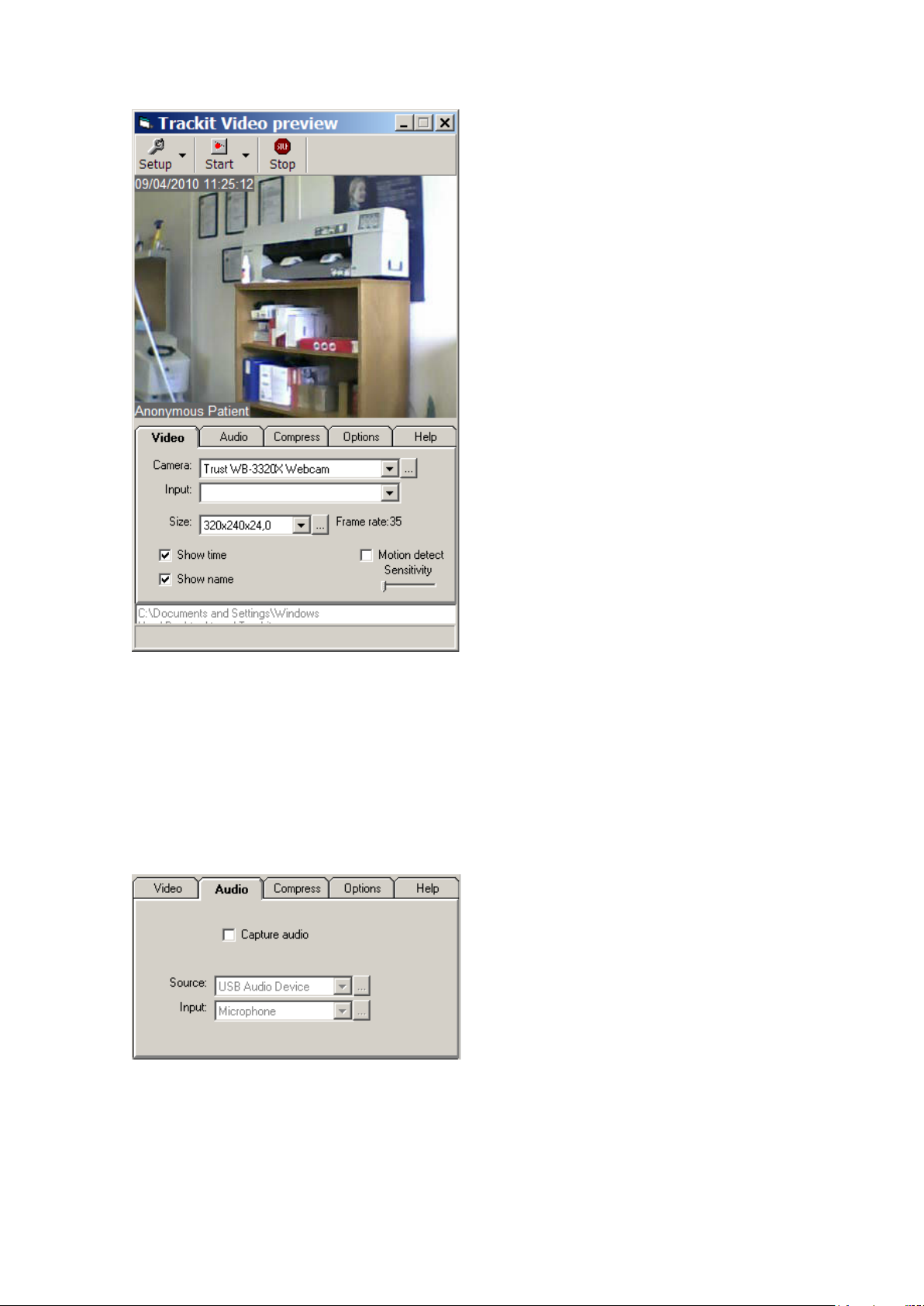
Trackit Mk3 User Manual
Figure 45 Trackit video preview
Video tab
The Video tab allows the camer a to be selected and also the picture size and fra m e r a te. If an excessively large picture siz e is inadvertently selected, the setu p ta bs c a n become inaccessible offscreen thus making re-sizing impossible. Under these circumstances the Setup button has a d r op down option which can be used to reset the video resolution.
Audio tab
The Audio tab allow s a n optional microphone to be selected.
59
Page 60
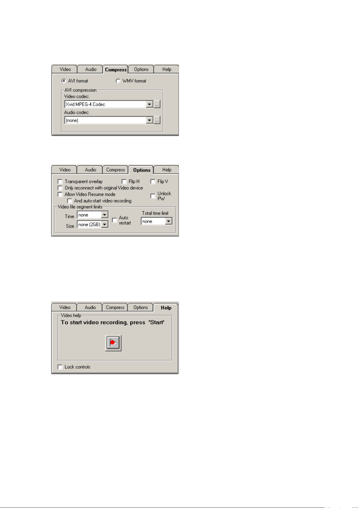
Trackit Mk3 User Manual
Compress tab
The Compress tab allows th e c ompr es s ion codec to be selected.
Options tab
The Options tab allow s various options to b e selected as shown below.
Video can automatically resume af te r an interruption and will use only the orig inal camera.
Video file segment size can be s elec ted or disabled.
Unlock PW makes a password necessary to unlock the controls. The password is the Recording ID.
Help tab
The Help tab provides a single large button which the patient can u se to start and stop the rec or d ing.
Lock controls prev ents access to the s e tup settings. It is res et from the Setup drop -down.
Start recording
At the commencement of a recording, th e video file name and destination need to be en tered.
60
Page 61

Trackit Mk3 User Manual
Appendix 5: Bluetooth Wireless
Introduction
Using a single plug-in Bluetooth interface m odule on the Trackit Mk3, wireless connections can be
established with it from any Bluetooth-enabled PC, Laptop or PDA. This allows the Trackit Mk3 to
be controlled or monitored remotely over a secure wireless link up to a range of a b out 100m or
greater (dependent on har dware and environmental factors ).
Bluetooth primer
It is not intended h e r e to provide a full intr oduction to Bluetooth technology, how it works and how
to use it. There is a huge amount of information elsewher e that is available for th is purpose. Nevertheless, a sh or t de s cription will be given to identify some of the common terms th a t will be used
later in the document.
The term "Bluetooth" refers to a worldwide standard for the wireles s exchange of data between two
devices.
In order to exch a nge data, two Bluetooth devices must establish a connection . Before a connection
is established, one device must req uest a connection w ith another. The second device acc epts ( or
rejects) the connection.
The originator of the request is known as the client. The device that accepts (or r ej ects) the request is known as the server. Many Bluetooth devices can act as both client and server.
A client Bluetooth device runs a software program that requests a connection to another device as
part of its normal operation. For e xample, the program may request a connection to a remote computer, a printer, a modem or a Trackit Mk3.
Becoming a Blue tooth client norma lly requires an action by the device operator, such as an attempt
to browse a remote com p uter, print a file, d ia l out on a modem or connect to a Trackit Mk3.
Every Bluetooth device that provides a service must be prepar ed to respond to a c onnection request. Bluetooth softw are is normally running in the background on the server, rea dy to respond to
connection requ ests.
Specification Summary
• The devices in a piconet share a common communication data channel. The channel has a
total capacity of 1 m eg a b it per second (Mbps). Headers and handshaking information consume about 20 percent of this capacity.
• In the United States and Europe, th e frequency range is 2,400 to 2,483.5 MH z, with 79 1-
MHz radio frequency (RF) channels.
• A data channel hops randomly 1, 600 times per second between the 79 RF channels.
• Bluetooth can tra nsmit up to 721 kilobits per s econd (Kbps) in on e dir e c tion, with 57.6
Kbps in the other. If the use calls for the s ame speed in both direct ions, a link with 432.6 Kbps capacity in each direction can be made.
• Each channel is divided into time slots 625 mic r oseconds long.
• A piconet has a master and up to seven slaves.
• Packets can be up to five time slots wide.
• Data in a packet can be up to 2,745 bits in len gth.
• There are currently two types of data transfer between devices: SCO (synchronous connec-
tion oriented for voice and audio) and ACL (asynchronous connectionless) .
• In a piconet, there can be up to three SCO links of 64,000 bits per second each.
• Masters can support u p to three SCO links with one, two or three slaves.
• Slots not reserved for SCO links can be us e d for ACL links.
• One master and slave can have a single ACL link.
• ACL is either point-to-point ( m a ster to one slave) or br oadcast to all the slaves.
• ACL slaves can only transmit when requested by the master.
• A Class 1 device has a maximum output pow er of 100mW (20dBm) and has a range of
about 100m.
61
Page 62
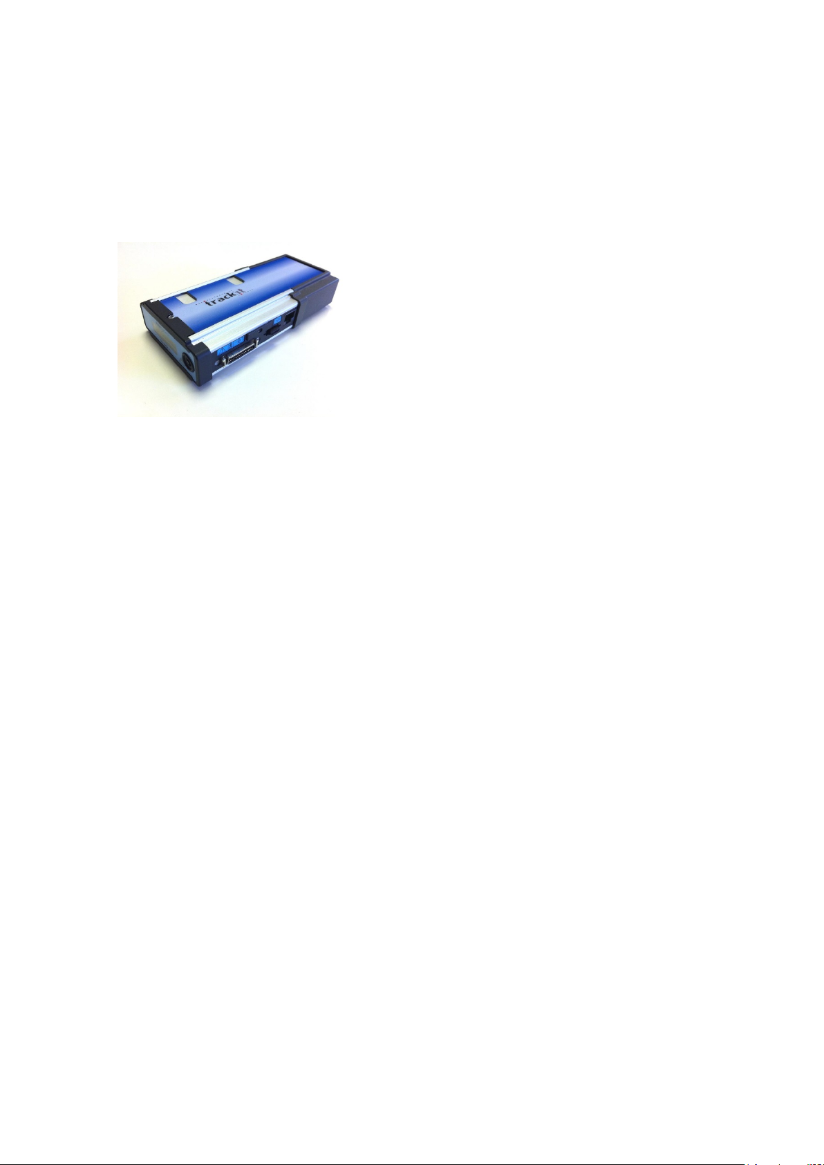
Trackit Mk3 User Manual
• A Class 2 device has a maximum outpu t power of 2.5mW (4dBm) and has a range of a bou t
20m.
• A Class 3 device has a maximum outpu t pow er of 1mW (0dBm) and has a range of about
10m.
System overview
The system and its parts
Figure 46 Trackit Mk3 with Internal Blue t ooth Module
Internal Bluetooth
Trackit Mk3 has built-in Bluetooth capability which can be ordered as an option. When present
there is a small ‘β’ on the display as shown in Figure 4 on page 19. This inter nal Bluetooth can be
enabled by pressing the pushbutton 5 times within 3 seconds whereupon the display will change to
a ‘B’. Note that when enabled, the normal serial cable communication with the host PC b ecomes
inoperative. At any time the B luetooth can be disabled by again pr es s ing the pushbutton 5 times
within 3 seconds . This will restore the s e r ia l cable commun ic a tion.
The module is qualified against Blu etooth specification V1.1 or V2.0 (la te r m od ules) and it will communicate with a ny similarly qualified Bluetooth device e ls e where. This means that the Bluetooth
host (client) can be any standard qu a lified Bluetooth periph e r a l device bought off-the-shelf. Lifelines does not supply the device at the host end and the User can make his own choic e from the
wide range availa b le. Note that to ach ie ve the maximum transmission range, this Bluetooth device
should be of the H igh Power (Class 1) type to m a tch the Trackit Module. Lower power devices
(Class 2 and Class 3) will still work, b ut the range will be less. The receiver sen sitiv ity should also
be as good as possible because this also helps to maximise the transmission range. Look for a sensitivity figur e of at least –80 dBm (for 0.1% B ER ) or better.
These standard qualified B luetooth devices are available as U SB converters, PC-card or CF-card
converters, S er ial Port converters a nd even built-in to PDA dev ices , Laptops and desktops. The
Trackit Mk3 will communicate with all these devices through the standard Trackit Setup or Wizard
Setup programs that have been enhanced to provide trans pa r ent Bluetooth functionality. T hese
programs will work over a direct connection, over a Bluetooth wireless connection or over a network or even over a combination of connec tions.
What you can do w ith a Trackit Bluetooth link:
• Connect wirelessly to any Track it within range equipped with a Bluetooth Module
• Control the Trackit wirelessly ( Acquire on/off, Ongoings on/off, Im p ed a nce Check on/off, Re-
cording on/off, Calibration on/of f etc.)
• Send setups to the Trackit wirelessly
• Review the Trackit status wirelessly (general system status as well as Trackit time, recording
time, battery level, disk level, SaO2 level, heartrate etc.)
• Monitor the Trackit Ongoing traces wirelessly
• Acquire wirelessly and record on a PC (this is using the Trackit as a wireless Headbox)
62
Page 63
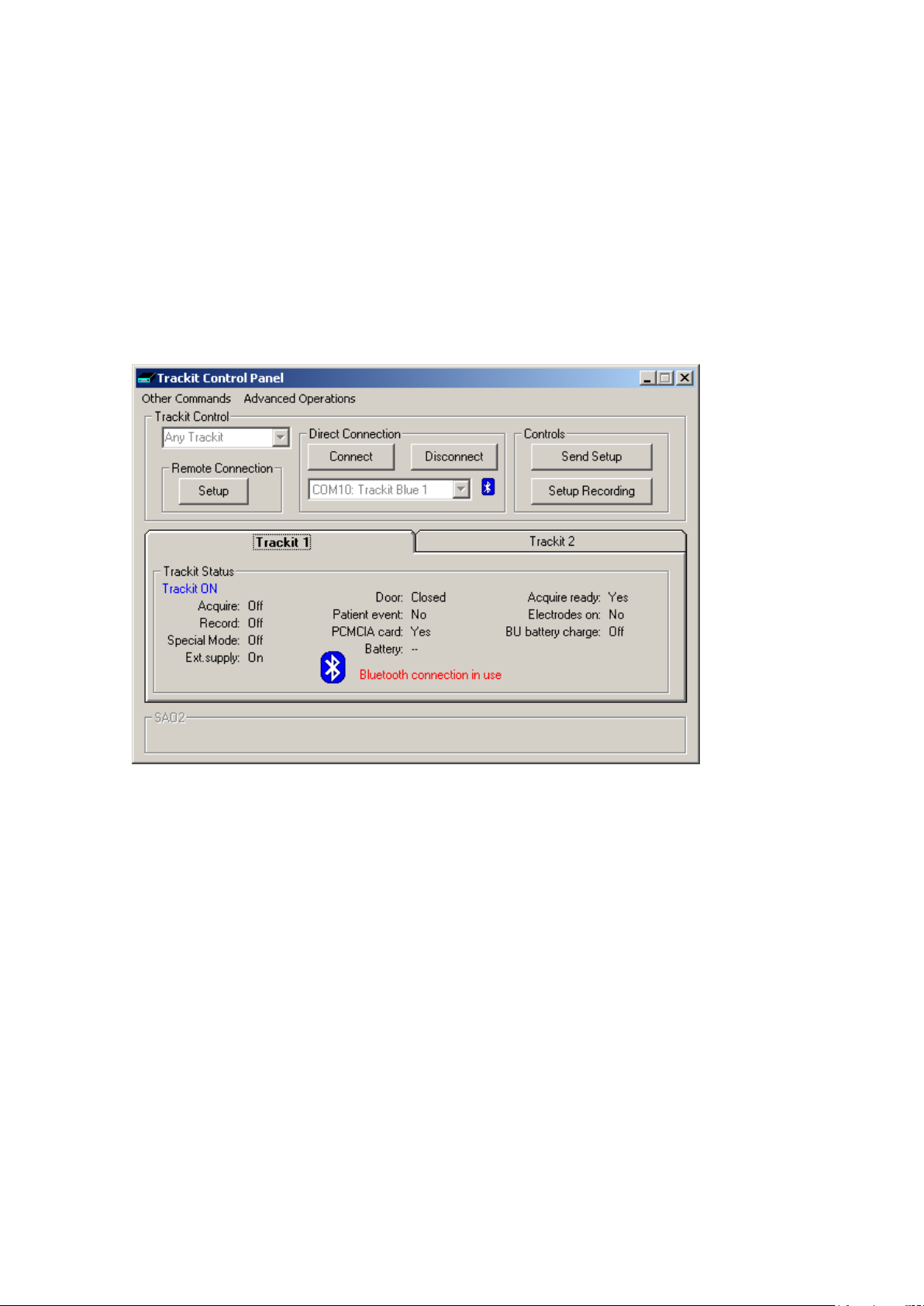
Trackit Mk3 User Manual
• Connect wirelessly as a second user (a Guest) and review Trackit status and also monitor Ongo-
ing traces, Imp.Check, Events etc.
• Mark an event over the wireless link
• Optionally configure the Trac kit to automatically record locally whenever the wireless lin k is lost
• Connect wirelessly and directly to s everal Trackits simultaneously f r om the same PC. These
Trackits are als o s imultaneously a vailable for Guest connections
Connection and use
The Trackit Setup and Tra ckit W iz a r d pr ogra m s have been enhanced to provide tra nsparent Bluetooth support. A ll the functionality of the programs is available over a direct connection or a Bluetooth connection . Note that the Tra c kit should be fitted w ith V2.10.x or later f ir mware.
Figure 47 below sh ows the new Trackit Control Panel with the ad ditional Bluetooth features.
Figure 47 The Trackit Control Pane l
The Port number selection drop-down lis t now supports a shor t d escription of the port. This can be
a direct hardwar e p or t ( e .g. Com 1) or any of the virtual serial por ts provided by Bluetooth (e.g.
Com 10). These Bluetooth ports are setup w ithin the Bluetooth a p plication running on the PC. The
connection is fir st established with the Trackit via a sear c h, a Comm. port number is assigned and
various encryption and pairing options defined. Th e Tr a c kit is always the serv er and pr ov ides the
serial port conn ection service to the P C acting as a client. T hereafter, the particular Trackit can b e
connected to by ref e r ence to its Comm. port number only – opening the port from the T rackit application automatically opens and establishes the Bluetooth link.
Figure 48 below sh ows a typical My Bluetooth Places view from the application on th e PC and
shows two available Trackit Bluetoo th connections. F or additional information about setting up connections, refer to your application doc umentation.
63
Page 64
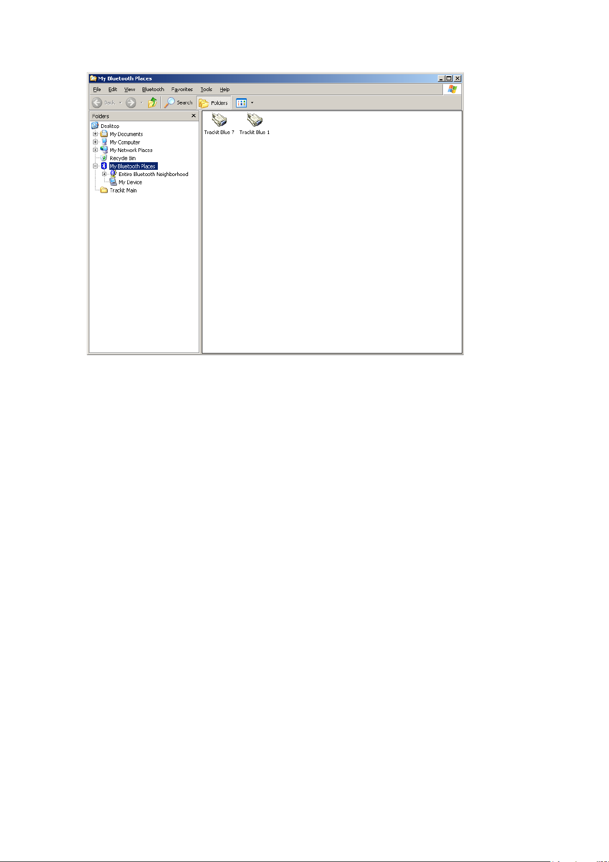
Trackit Mk3 User Manual
Figure 48 A typica l Bluetooth Plac es view
Once a Bluetooth connection is established, the Bluetooth icon is displayed on the Control Pan e l
and also against the port number. If the particular Track it is off or out of range or the P C Bluetooth
adapter is unplugged, the connection attempt will be unsu ccessful. If a connection already exists
with the particular Trackit from another PC (the MASTER), then the word “GU EST” appears next to
the Bluetooth icon. A GUEST has limited c ontrol functionality but can review most aspects of the
Trackit and its recording. If the MASTER disc onnects, then all G U ESTs are also disconnec ted . One
of these GUEST s can then, of course, a tte m pt reconnection as a ne w MASTER. This func tionality is
an example of the Bluetooth piconet feature (in serial por t terms it is sometim es referred to as
multi-drop in the same way th a t a har dware RS485 link can be multi-drop). In theory, there can be
7 devices in a piconet, although in practice this is very depen dent on data volume between the devices. Multi-drop is also s ometimes referred to as point-to-multi-point.
This piconet and m ulti-drop feature of Bluetooth offers v er y powerful and flex ible c onnection capabilities to the Tra c kit system. Not only can a single PC connect to any Trackit in r a nge, but another
PC (or perhaps PDA) can also connect simultaneously to th e same Trackit or any one of the other
Trackits. It is also possible to configure a Trackit Bluetoo th connection as a network server – in
which case a Trackit client can conn e c t to it anywhere on the n etwork (the fact that it is ultimately
a Bluetooth conn e c tion to the Track it is transparent to the c lie nt).
When the Track it a p plication has es ta b lis hed the Bluetooth c onnection, a connection quality monitor labelled “Com m s.Q” is displayed in the s tatus bar at the bott om of the main screen, as shown
in Figure 49.
64
Page 65
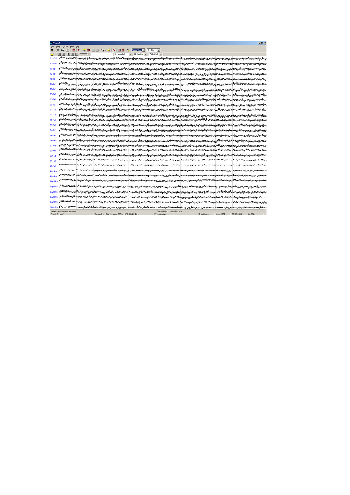
Trackit Mk3 User Manual
Figure 49 Trackit Main Screen
This number given as a percen tage is a n approximate indication of th e a m ount of data received as
a ratio to that expec ted, calculated eve r y second. It is most likely to drop belo w 100% during the
transfer of ma ny ongoing traces. I t can also drop when either de vice is at the limit of th e tr ansmission range or when either antenna is adversely obscured. It will be noticed that the Blu etooth
transmission w ill use its available bandwidth to try to “c a tch-up” after a drop in signal quality and
the indication can read m ore than 100% momentarily. A rea ding, therefore, of less than 100%
does not necessarily mean a permanent bad connection since data flow can increase shortly afterwards. A sustained low value over se veral seconds will cause the Trackit app lic ation to close the
connection. I f the Autoconnect fe a ture has been enabled in Options, the application will automatically attempt to reconnect to the designated Trackit ev e r y 10 seconds.
Note: Under certain circumstanc es the Bluetooth comm p or t is not identified by the software as a
Bluetooth port and the Bluetooth icon will not appear in Figure 47 The Track it Control Panel, when
connected. Th is can happen depending on which Bluetooth sta ck is installed and the version of
Windows. It is im p or ta nt that the software does identify Bluetooth virtual comm ports correctly
since various internal parameters a re optimised. See next section for a s olution to this problem.
65
Page 66
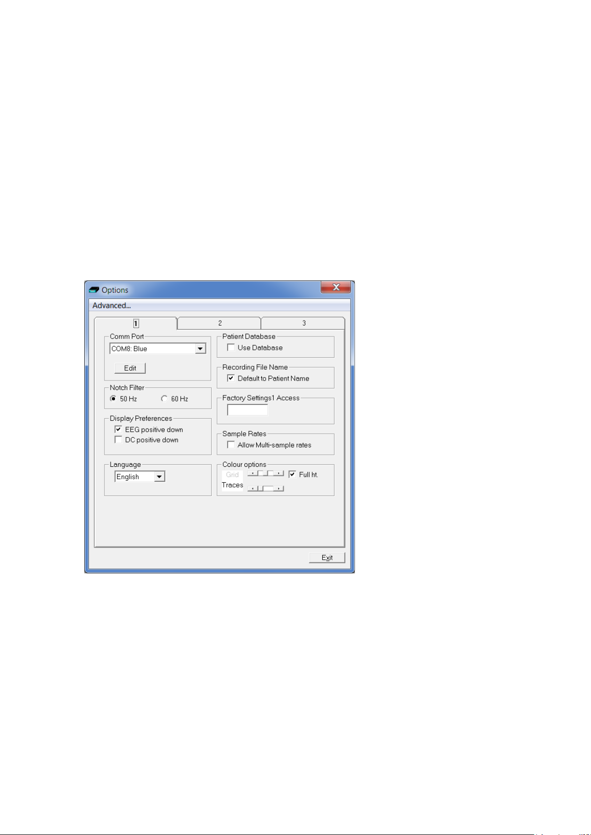
Trackit Mk3 User Manual
Application PC Setup
There are two aspects to Settin g Up – firstly, the Applica tion running on th e P C and s ec on dly, the
Trackit and its Bluetooth Module. Both parts of the setup a r e accomplished from the PC. This sections covers the A p plic ation setup, the next section th e Trackit setup.
Options | Tab 1
The Options pane l now includes two tabs a s shown in Figure 50 below. Tab 1 contains the same
option settings a s before but with s om e a dd itions concernin g the Comm. Port assignm e nt. By clicking on the Edit button , each Comm. Port can be assigned a des c r iption. This description helps in
the identification of which Track it is to b e connected to (and thereafter which Trackit is being controlled). It applies to the Trackit Bluetooth Module and if this is moved from one Trackit to anothe r ,
the connection f ollows the Module not the Trackit. Each Module has a unique name that can be repeated here if desired, or som e oth er naming convention used. N ote th a t th er e m a y well be hardware ports, USB p or ts and Bluetooth ports – all of which can be us ed by the Trackit applicati on.
All description s for all Comm. Ports are saved in the registry, so they only need s e tting once.
Figure 50 Option s T a b 1
Note: When the Bluetooth comm port is n ot identified correctly by the software a s a Bluetooth port
(see previous section), th e por t n a m e c a n be edited and the word ‘Blue’ added to the description as
shown above.
Options | Tab 2
The second tab in O ptions is shown in Figure 51 below.
66
Page 67
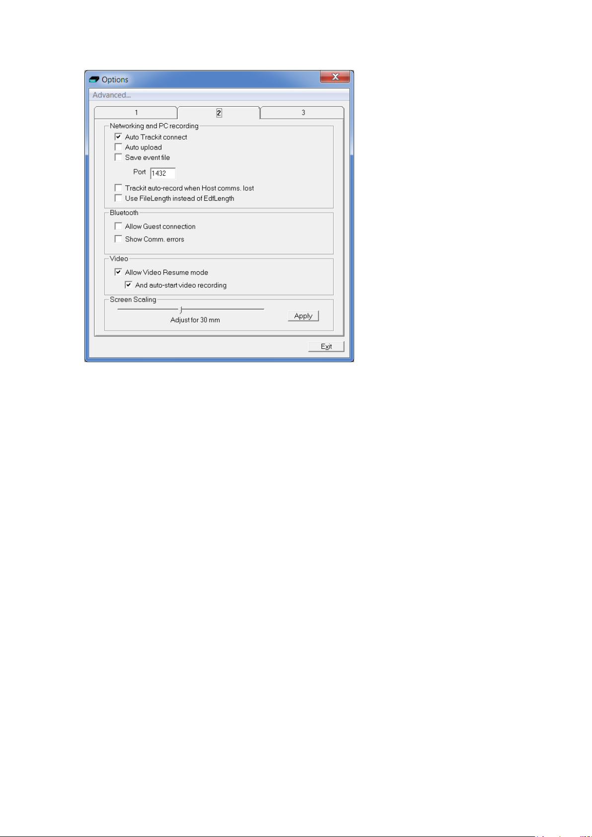
Trackit Mk3 User Manual
Figure 51 Option s T a b 2
Networking and PC recordin g Opti o ns (Trackit plus o nly )
• Auto Tra cki t con nect. If ticked this will caus e the application to attempt to reconn ect to the
designated Trackit after a disconnect. The disconn ect can be loss of Blu etooth link or unplugged cable etc. N ote that it is not a manual disconnect, which cancels the Autocon nect feature. Autoconnect starts after the first manual conn ection.
• Autoupload. If ticked this will cause the applic a tion to automatically upload the Trac kit’s setup
immediately after a connection is established. It is on ly enabled if Auto Tr a ckit Connect is enabled.
• Save Event File. If ticked this will cause the application to a utomatically u ploa d the Trackit’s
event file immedia tely after a con nection is establish e d and save it in a tempora ry file called
TempEve1.tev in the defa ult application path. This file can be viewed or emailed out at a later
time with or without the Trackit conne c ted . It is only enabled if A uto Trackit Connect and
Autoupload are enabled.
• Port. This is the port number that the application u ses for its TCP networkin g c onnection. For
the client, this des ignates the local port to send data from. For the server, this is the local port
to listen on.
• Tracki t auto-record when Host comms. lost. If ticked the Trackit will autom a tically start re-
cording when the Host communication is lost if it has been in Headbox mode (Host PC recording). This featu re is most useful with a wireless Bluetooth connection, but it w ill work for any
type of connection. If there is already a file on the Trackit dis k, then the usua l ru les apply :
1. The Trackit will not overwrite a file less than 24 hours old
2. The Trackit will append new data to a file less than 24 hours old if the Patient N a me, ID,
recording setup a nd all other details are ide ntical to its cu r rent setup
3. The Trackit will overwrite in a ll other cases
Note that the Trackit will not automatically stop recordin g upon reconnection. This must be done
manually from the Host if required.
67
Page 68
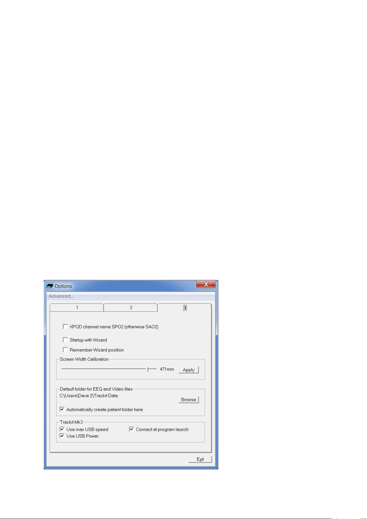
Trackit Mk3 User Manual
• Use File Length in stead of EDF Length. This a playback feature and if ticked, the file length
is used instead of the edf length pa r a meter em bedded in the edf header. Due to the fact that
the Trackit’s memory card can be removed at any time, there can be a partial 1s data block at
the end of the file a nd so the actual size m a y not be an exact multiple of 1s.
Bluetooth Options
• A llow Guest connection. If ticked this will allow the a pp lic ation to become a Bluetooth
GUEST. Before actual connection the application will l is te n on the connection to ascertain
whether a MAST ER is already in control of the designated Trackit. In these situation s, the new
application becomes a GUEST connection if allowed. Note that this option concern s the application only. Ther e are other options tha t c onfigure the Trac kit and the Bluetooth m od ule as regards GUEST connections (see below).
• S how Comm. errors. This allows any Comm. errors to be display ed on the main screen s tatus
bar below the Patien t ID. This applies to all connections, whether direct, USB or Bluetooth. It
can be useful when assessing signal quality.
Video
• A llow Video Resume mode. This allows Video synchronised recordings to be r es umed after
the PC has been powered-off.
• A nd a uto start video recording. This allows the video to automat ically start recording after a Video Resume has occur r ed.
Screen Size
This Slider Bar allows the screen size to be s et so that the Chart S peed for the traces exactly
matches the cm/ s s e lected. To use, adjust the slider so that it is 30 mm from the left-hand end.
Options | Tab 3
68
Page 69
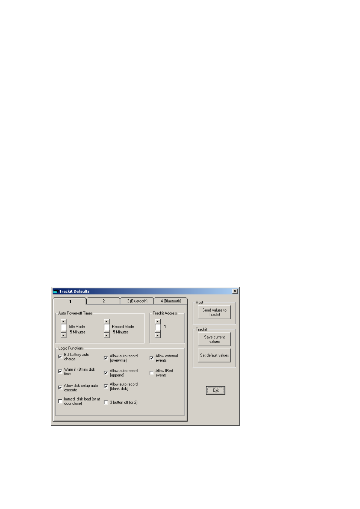
Trackit Mk3 User Manual
• XPOD channel name SPO2 (otherwise SAO2). This option allows the XPO D c hannel name to
be either SPO2 or SAO2. This is because some playback software requires a specific label to
enable recognition.
• S t ar t up with Wizard. If checked , the Trackit program will next sta r t with the Wizard.
• Remember Wiza rd position. If checked, the last Wizard window position will be remembered
and recalled. Oth erwise it will appear centrally.
• Screen Width Calibration. This allows the program to be calibrated to the sc r e en width.
• D efault folder f or E E G a nd V ideo files. This allows the program to always record EEG and/ or
video files to the sa m e de fault folder. Use Browse to find and/or create the default folder for
recordings.
• Automatically create pati ent folder here. If checked, the program will automatically create a patient folder in the default recording folder s et above without an y user
intervention. If not set, the user choses where to save th e r e c ording using the standard
save file dialogue window.
Trackit Mk3
• Use max USB speed. Normally this would b e c hecked. Can be use d to only allow a slower
speed to overcome connection pr oblems.
• C onnect at program launch. If checked, the program will automatically conn e c t to the Trackit
at launch. Only a p plie d to the Trackit M k3 USB interface.
• Use USB Power. Normally checked. Can be used to stop the Trackit using USB power and use
its batteries instead.
Trackit and Bluetooth Module Setup
The Trackit and the Bluetooth Module are setup from the Tra c kit Defaults screens. These h ave been
enhanced to include 4 tabs as shown in Figure 52 below. Tab 1 contains the same options as before.
Trackit Default Options | Tab 1 (General)
Figure 52 Trackit Defaults Tab1
69
Page 70
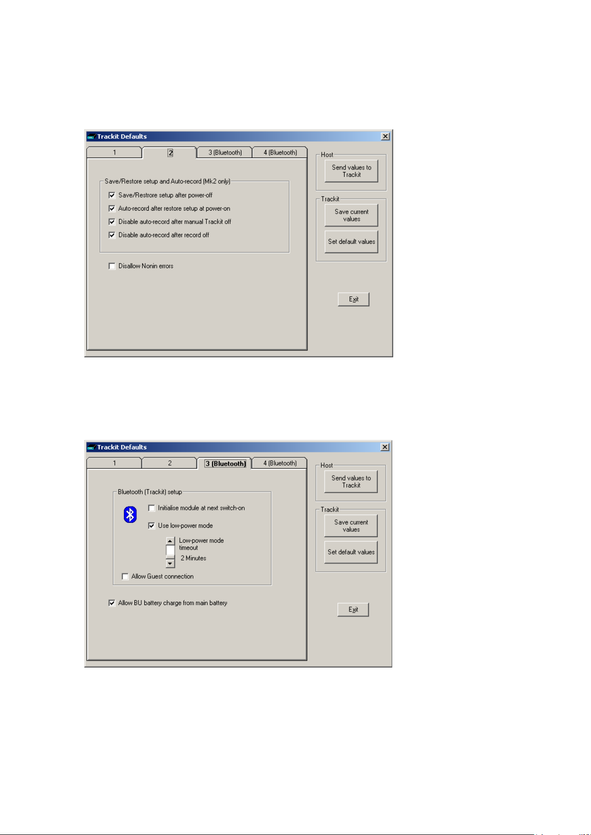
Trackit Mk3 User Manual
Trackit Default Options | Tab 2 (General)
These are additional options not sp ec ifically related to Bluetooth. Please refer to section 5.6 for
details.
Figure 53 Trackit Defaults Tab2
Trackit Default Options | Tab 3 (Bluetooth Trackit)
Tab 3 contains th e first set of Bluetooth options as shown in Figure 54 below.
Figure 54 Trackit Defaults Tab 3
Bluetooth (Trackit) setup
• Initialise modul e at next switch on. If at any time the Bluetooth Module setup becomes corrupted, this option will instruct th e T rackit to initialise it with default settings when it is next
switched on. The usual method would be to use a direct connection for setting the opt ion (if
70
Page 71
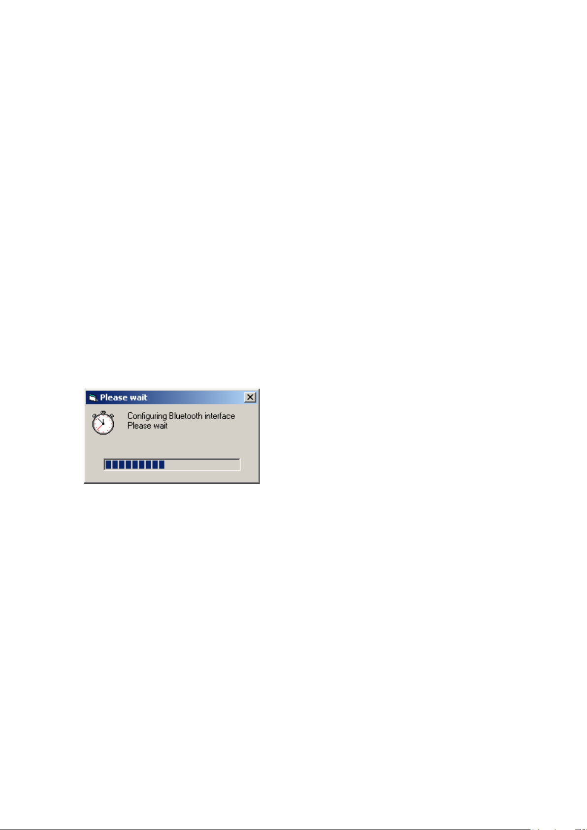
Trackit Mk3 User Manual
the Bluetooth lin k would not work), s witch-off the Trackit, c onnect the Bluetoot h Module to the
Trackit and switch-on. The Trackit will reme m be r its initialisati on task, will detect the Bluetooth
Module and initialise it with defa ult values (sufficient to enable it to work). Note that it can take
several seconds for the Trackit to do this – do not change a nything until the Trac kit is ready.
The Trackit will only do this initialisation once – even if pow er ed of f and on again, until instructed again to do it. Also note that at switch-on, if the Trackit does not detect the Bluetooth
Module, the remembered instruction is cleared.
The situations whereby a Blu etoo th Module might become corrupted a re very rare, however
due to the complexity of Bluetooth an d the full access given to a ll the setup parameter s , it is
possible that inad vertent or inex pe r ienced operation may cause incorrect s ettings. It should
also be noted that it is possible to allow the s e tup of the Bluetooth Module to occur over a
Bluetooth connection (refer later) . This could allow unexpected connections to interfere with
the Module setup.
• Use low-power mode . Only use this option for the early external first generation Bluetooth
Module. If ticked this option instruc ts the Trackit to put the Bluetooth Module into a low-power
state after a period of no connection (the configurable tim e r is d escribed below) . This low
power state contr ibutes significantly to extending th e Trackit’s battery life whilst still of fering all
the desirable fea tures of Bluetooth . In this state the Module is still discoverable and connec ta ble, but upon con nection it must be tak e n out of the low-power state. Th e a pplication detects
whether the Module is in low-power state a nd if so instructs the Trackit to set the Module to
normal mode. To accomplish this, the Bluetooth connection must be dropped mom e ntarily and
then re-connected. The entire process is automatic and takes about 5 seconds. Refer to the Appendix for details of the low-power mode power savings. Note th at when using the new G eneration Bluetooth Modules (OEMSPA332i and OBS433i) there is no benef it to using low power
mode, so the option should be left off. During the connection time, the applica tion displays the
following :
• Low-power mode time out. This option allows the se tting of how many m inutes of no connec-
tion must elapse before the low-power m ode comes into operation.
• A llow Guest connection. If ticked this option instructs the Trackit to accept more than on e
simultaneous Bluetooth connec tion. Note that there is a separate enable for the application
(described on page 67).
General
• A llow BU battery charge from main battery. Now that it is possible to con nect to the Trackit
wirelessly, it is n o longer possible in these situations to charge the Trackit’ s b a ckup battery
from the Isolator, as was previously p os sible with a direct wir ed c onnection. It is impor ta nt that
the backup battery is charged because it pr ovides power to the Trackit’s internal c loc k/calendar
chip and also prov id es p ower to enable the Tra ckit to continue recording for a short wh ile during main battery r ep la c e ment. This option, if ticked, enables the Trackit to use its main battery
for charging its backup battery. The Trackit only ever charges its backup battery once at
switch-on and only after a 10 min ute rest period (in ca s e the Trackit is switched on and off repeatedly in quic k succession). Add itionally, the Trackit will only use power from its main batteries if they are within 75 – 100% of their capacity, i. e. fresh batteries. Furtherm ore, the
Trackit will only c harge its backup batte r y for a period of 10 minutes. All this means that the
backup battery will receive a 5% charge at every Trackit switch-on at the expense of a 0.5%
drop in main battery capacity (assuming a single alkaline battery – it will obviously be proportionately less of a reduction for more main batteries). U s ing this option it is pos sible to disable
71
Page 72
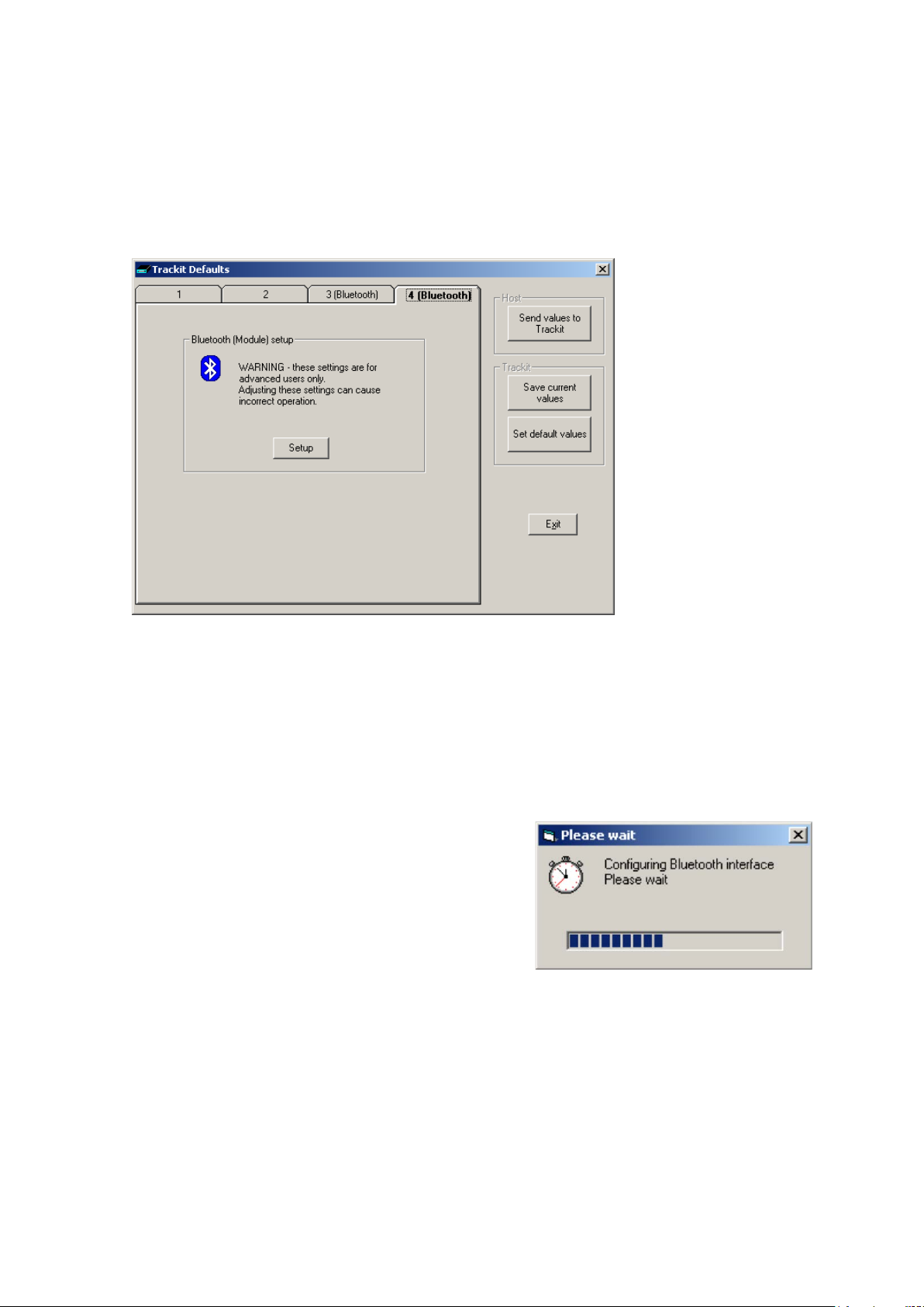
Trackit Mk3 User Manual
this feature if a regular connection to the Isolator is made. Also note that it is pos s ible to manually initiate a backup ba tter y c harge sequence.
Trackit Default Options | Tab 4 (Bluetooth Module)
Tab 4 contains th e third set of Bluetooth options as shown in Figure 55 below.
Figure 55 Trackit Defaults Tab 4
CAUTION : Access is prov id ed here to the full set of Bluetooth configuration parameters in the
Module. Adjusting these settings can cause incorrect operation. Please contact your Trackit Service
Representative before adjusting these settings.
The setup of the Bluetooth Module itself is accomplished over the Bluetooth link currently established. This mea ns that no extra har dware is required to connect in some other way to the Module
– it remains conne c ted to the Trackit.
Clicking on the Setup button instru c ts the Trackit to enter
a special mode to enable the setup-over-Bluetooth function. During this time the connection must be dropped
momentarily and then re-connected. The entire process is
automatic and takes about 5 seconds.
After the configuration process has finished, access is
provided to the main B luetooth Setup pane ls shown below.
Bluetooth Setup | Tab 1 (General)
The Bluetooth Setup screen is sh own in Figure 56 below. It should be noted that even though the
Trackit has put the Bluetooth Module into the special Setu p -over-Bluetooth mode, no changes are
allowed until a special comm a nd sequence has been sent to the module. This procedure guards
against casual browsers being able to adjust settings (there is much more in formation about security later on). Clicking on the Connect button sends the special command and also reads from the
Bluetooth Modu le all its current settings which are displayed in the various tab panels.
Clicking on the Read button causes a re-read of all the Module’s pa r a m eters .
72
Page 73
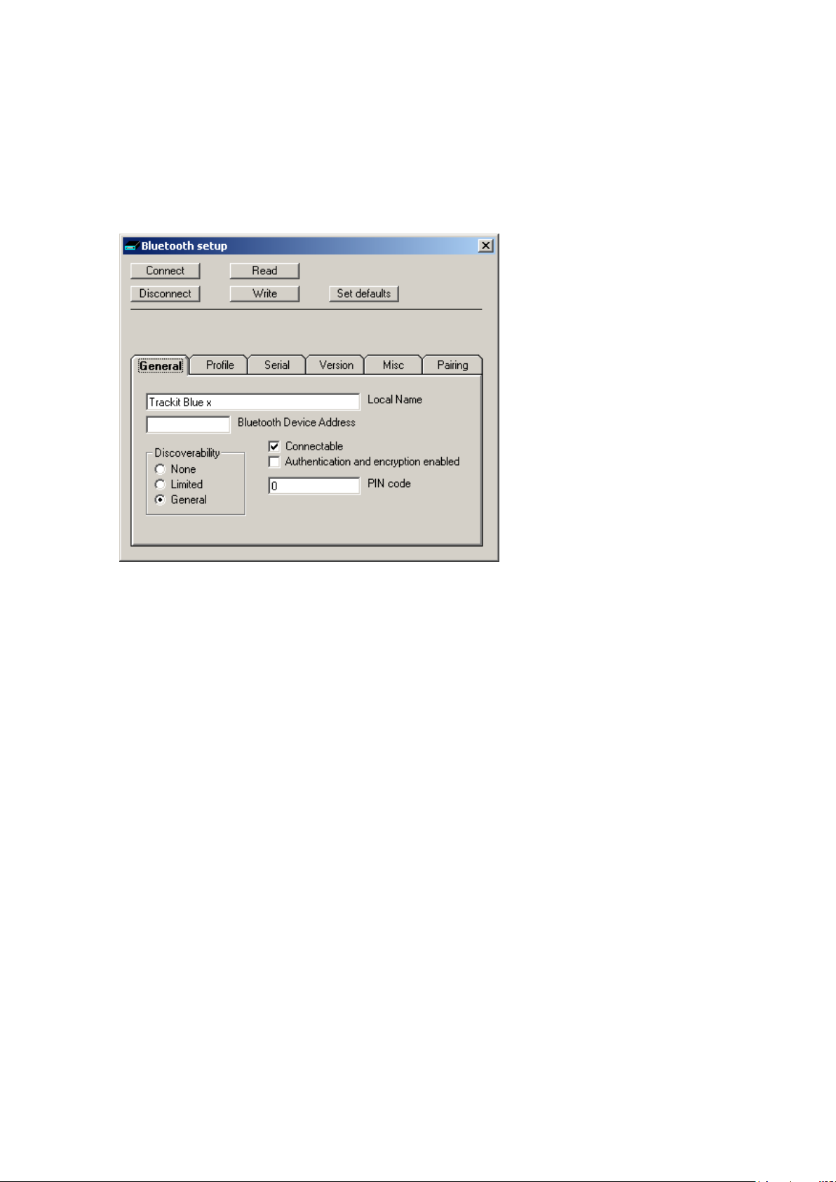
Trackit Mk3 User Manual
Clicking on the Write button causes all values currently being displayed to be written across to the
Module which s tor es them in its non-vola tile memory.
Clicking on the Set defaults button loads defa ult values into all displayed settings ( these are not
sent to the Module until a Write occurs).
Clicking on the Disconnect button finishes the setup session and issues commands to disable
changes to the Mod ule setup and also to ta ke it out of Setup-over-Bluetooth m ode . The Module is
now ready for us e with the new settings.
Figure 56 Trackit D e faults | Blue t ooth S e tup Tab 1 (Gene ra l)
• L ocal Name. This allows the M od ule to be given a ‘frien d ly name’ (in a simila r wa y to a networked computer). This name is the one reported by other computers during a search or connection. If there are several Trackit Bluetooth devices on-site, it is important that each ha s a
unique name. As supplied, every Module will be uniquely na med a nd this will be in the form of
‘Trackit Blue x’ where x is numeric. D o not change the name unless there is a good reason to
do so.
• B luetooth Device Address. Every Bluetooth device is assigned a unique address (in a similar
way to the IP address of a network adapter). The address is read-only and cannot be changed.
The Module can be r eferred to from a remote d e vice by either its local name or in some situations by its Bluetooth Device Addres s .
Discoverability
• None. If selected the Module cannot be discover ed by other devices during a search – it becomes invisible.
• Limited. If selected the modu le becomes only partially discoverable.
• General. If selected the Module can be discovered by other devices.
• Connectable. If ticked the Module can be connected to by another device. Otherwise a con-
nection is not allowed. The application forces Connectab le.
• A ut hentication an d e n c ryption enabled. If ticked the remote device must k now th e Module’s
PIN code passkey to be able to conn ec t. The Module undergoes a ‘pairing’ pr ocedure with the
remote device. Additional ly in this mode, all data transf er s a r e encrypted using the same PIN
code as a passkey.
• PIN code. This is the code that must be known to the remote connec ting device to enable a
connection to be made. The code is en ter ed once only during the ‘pairing’ procedure on the
host (client). I t can be set here in the module to any numeric sequence. It is only used if Au-
thentication and e ncryption is enabled in the Module or the remote device requires authentication.
73
Page 74
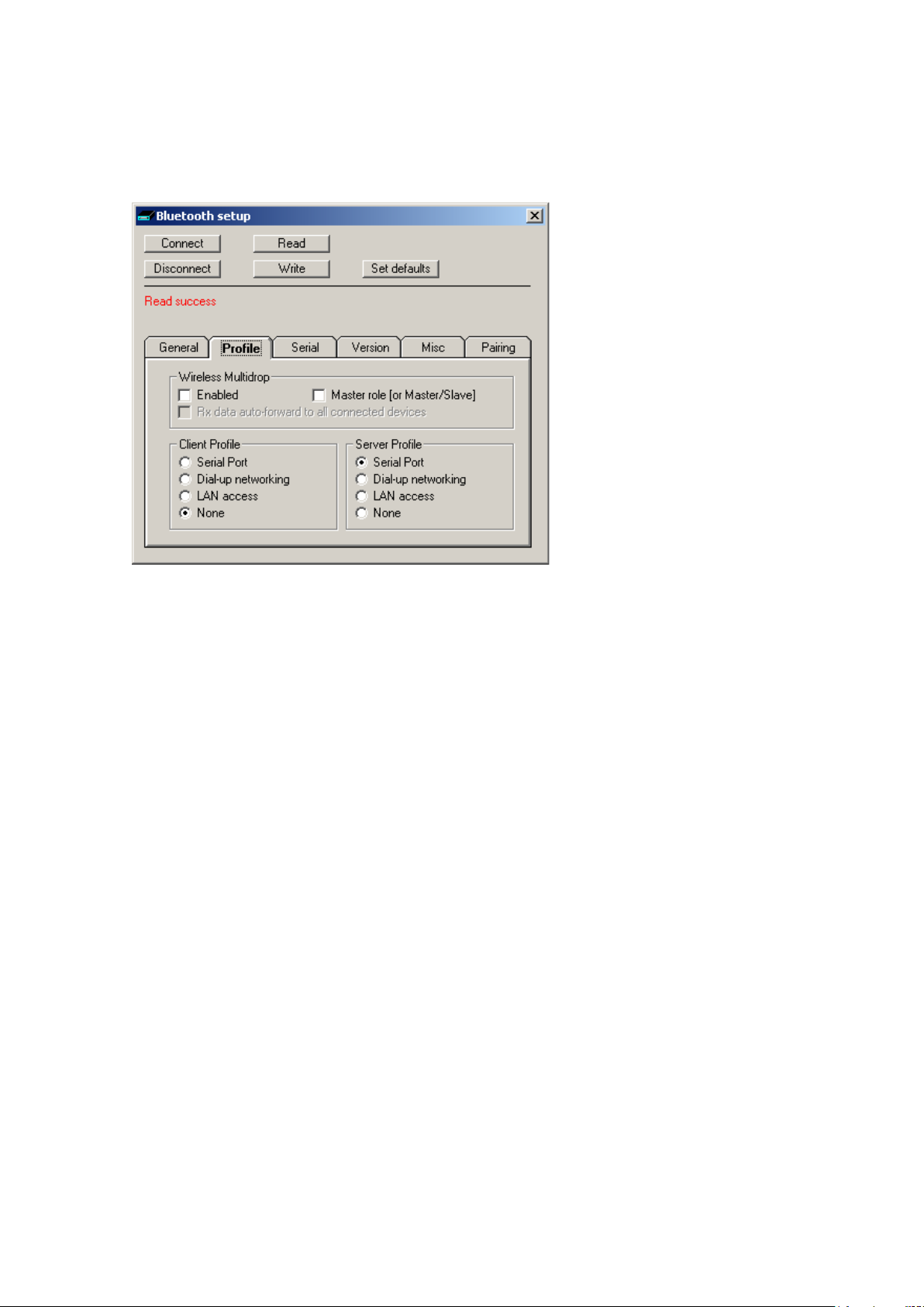
Trackit Mk3 User Manual
Bluetooth Setup | Tab 2 (Profile)
Tab 2 contains th e s econd set of Bluetooth options as shown in Figure 57 below.
Figure 57 Trackit Defaults | Bl ue tooth Setup Tab 2 (Profile )
Wireless Multidrop
This section cov er s the multiple-conn ection capabilitie s of the Module. It is pos s ib le for several
Bluetooth devic es within range of each other to set up a ‘pic onet’ amongst themselves, whereby
each device can have connections to several other devices simultaneously. In this mode several remote devices can connect simultaneously to the same Tra ckit. All data transm itted by the Trackit is
transmitted to al l c onnected clients (the individual applications filter out the specific data of interest). For received d a ta , the Trackit receives all data transmitted by all clients (the Trackit ma intains
a separate data flow path for each client).
In Trackit terms , the first connection is the MASTER and it has full control capabilities. Subsequent
connections becom e GUESTs and they have limited control capa bilities. It is pos s ib le to individually
enable each clien t a p plication as to w hether it can become a Guest connection or n ot.
It should be noted that not all remote B luetooth devices handle multidrop/pic onet connections very
well and some will experien c e dr opped c on nections and loss of data. Refer to the Knowledge Base
for additional in formation.
It should be noted that within the B luetooth specification there is provision for such piconets to
themselves connect to other piconets – the combination being called a ‘scatternet’. In such a situation, each picone t m ust designate a Ma s ter device with all the others in the picone t be ing Slaves. It
is the Masters in each piconet which maintain the scatternet. Such a complex top ology is beyond
the scope of this document but the brief de s c ription is given for completeness. It is the reason for
providing the Master role [or Master/Slave] optio n in the panel.
• Enabled. If ticked several remote devices can c onnect simultaneously to the same Trac kit. Otherwise multiple connections are dis a b led . Note that if ticked then the Master role [or Mas-
ter/Slave] should also b e ticked. If untic ked then the Master role [or Master/Slave] should
also be unticked.
• Master role [or Master/Slave]. In some of the more complex topologic al arrangements it is
sometimes necessary for a device to switch from being a Master to a Slave and vice-versa. In
the Trackit situation this parameter should have the sam e s e tting as that for the Enabled parameter. If Enabled is ticked then Master role [or Master/Slave] should also be ticked. If
Enabled is unticked then Master role [or Master/Slave] should also be unticked.
74
Page 75
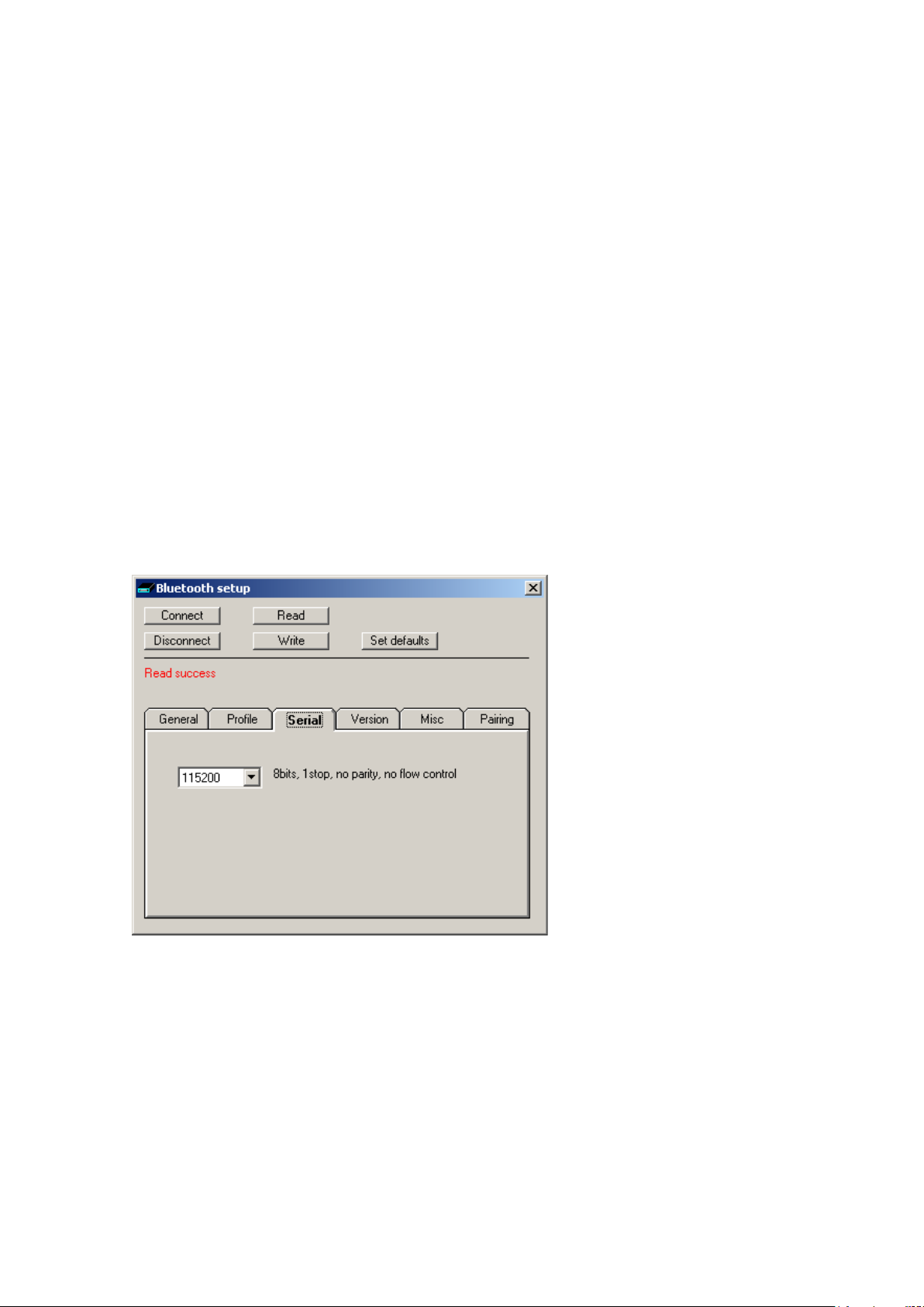
Trackit Mk3 User Manual
Client Profile
• Serial Port
• Dial-up networking
• LAN access
• None
This lists all the possible services offered by the Module w hen operating as a client. In the Trackit
situation, th e Module is always the s erver (it accepts incom ing connections) a nd never a client.
This option shou ld only be set to None.
Server Profile
• Serial Port
• Dial-up networking
• LAN access
• None
This lists all the possible services offered by the Module wh en operating as a Server. In the Tra ckit
situation, th e Module provides a Se r ia l Port Protocol serv ice (SPP) and this is the only option that
should be selected.
Bluetooth Setup | Tab 3 (Serial)
Tab 3 contains th e third set of Bluetooth options as shown in Figure 58 below.
Figure 58 Trackit D e faults | Blue t ooth S e tup Tab 3 (Seria l)
This option displa ys the current Baud rate of the Module. The application defaults it to 115200
Baud which is su ita b le for Trackit Mk1 ap plications. For Trackit Mk2 applications , the connection
speed is 230400 Bau d. Note, however, that when configuring over a Bluetooth conn e c tion, it is not
necessary to change this parameter from the default.
Bluetooth Setup | Tab 4 (Version)
Tab 4 contains th e fourth set of Bluetooth options as show n in Figure 59 below.
75
Page 76
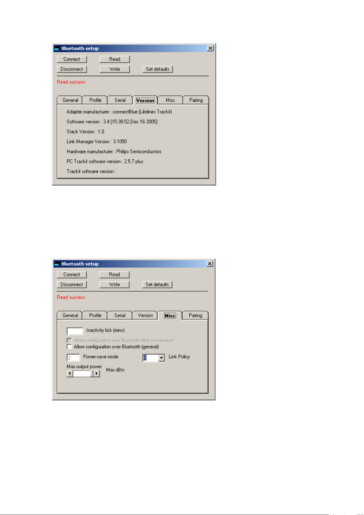
Trackit Mk3 User Manual
Figure 59 Trackit D e faults | Blue t ooth S e tup Tab 4 (Version)
Here is listed all the versions of the va r ious hardware and s oftware components in the system.
Bluetooth Setup | Tab 5 (Misc)
Tab 5 contains th e fifth set of Bluetooth options as shown in Figure 60 below.
Figure 60 Trackit Defaults | Bl ue tooth Setup Ta b 5 (Misc)
• I nacti v i ty ti ck. This option allows the Module to disconnect after a defined period of no data
activity. The T rackit application alw a ys transmits heartbeat (keep-alive) packets during connection, so this option r e a lly only applies to con nections from othe r types of remote device. To enable the option the desired timeout per iod in minutes should be entered. To disa b le the option
a zero should be entered. In normal situ ations the option sh ould be disabled.
76
Page 77
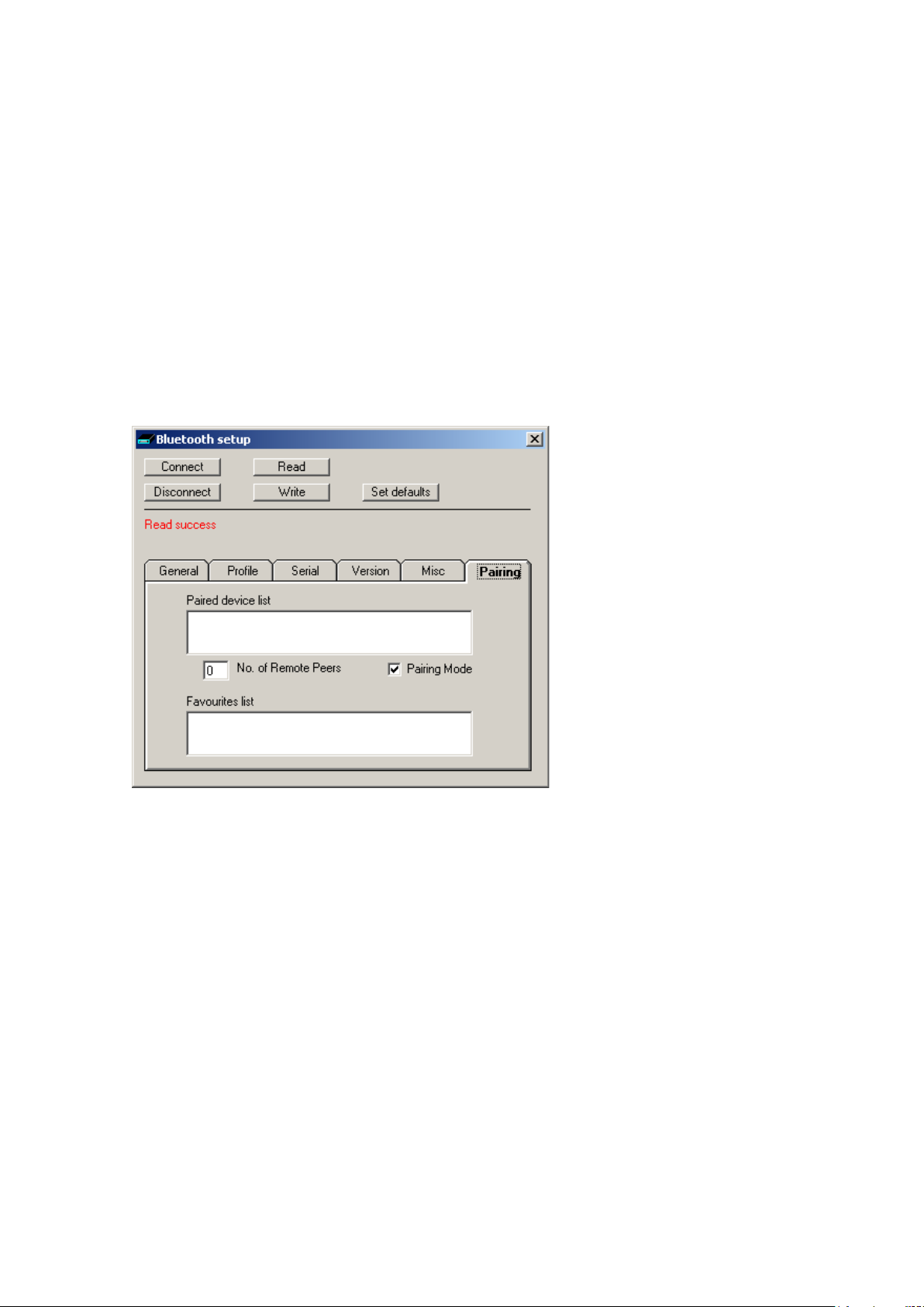
Trackit Mk3 User Manual
• A llow configurati on over Bluetooth (this connection). This is a read only parameter and
simply indicates the fact that the cu rrent connection is a llowing configuration over Bluetooth.
• A llow configurati on over Bluetooth (general). In contrast to the above, this option allows
the Module to be permanently enabled for configurati on over Bluetooth (after this session is
closed). This is normally on ly used for advanced and debugging purposes a nd the option should
be unticked.
• Power-save mode. This option defines the power-sa ve mode for the Module. Currently this is
fixed at an optimum setting.
• M a x . output power. This option defines the maximum Radio Frequency (RF) output power
from the Module. Currently this is fixed at an optimum setting.
• Link Policy. This is an advanced option and sh ould not be changed.
Bluetooth Setup | Tab 6 (Pairing)
Tab 6 contains th e fifth set of Bluetooth options as shown in Figure 61 below.
Figure 61 Trackit D e faults | Blue t ooth S e tup Tab 6 (Pairing)
• Paired device list. This lists the current Paired device addresses stored in the module.
• N o. of Remote Peers. This is fixed at 0.
• Pairing Mode. Sets Pairing Mode on or off . The default is on.
• Favourites list. This lists the current Favourites device a d dresses stored in the m odule.
77
Page 78

Trackit Mk3 User Manual
Trackit Bluetooth Module Specifications
Note: Lifelines reserves th e r ight to change product specifications at a ny time without notice. This
is in-line with the company’s policy of continual produc t development.
There are several version s of the Bluetooth Module: Type 1 is designed to be connected to the
Trackit Mk1 or Mk1+ and Ty pe 2 th e Trackit Mk2. These have a 9-pin and 15-pin micro-D connector fitted resp ectively. Additionally, there are two versions of the internal Bluetooth cir c uitry:
Original (OEMSPA33i) and 3rd Generation (OEMSPA332i) and the la test 4
rd
The 3
nal. The 3
and 4th generations are significantly smaller a nd lower power consumption than the Orig i-
rd
Generation was intr odu c ed in May 2006, the 4th in January 2012.
th
Generation (OBS 433i).
These versions are identified as follows:
1. Original Type 1 for Trackit Mk1. P a r t nu m ber ma r ked on cable 6738-000. Lifelines part 1048.
2. Original Type 2 for Trackit Mk2. P a r t nu m ber ma r ked on cable 6738-100. Lifelines pa r t 1121.
3. 3rd Generation Type 1 for Trackit Mk1. Part number marked on cable 6738-200. Lifelines part
1048.
4. 3rd Generation Type 2 for Trackit Mk2. Part number marked on cable 6738-300. Lifelines part
1121.
rd
5. 3
Generation Internal for Trackit M k2 and Mk3 only.
th
6. 4
Generation Internal for Trackit Mk3 only.
Note that the 4
th
Generation module has a much improved range, refer below.
Parameter Data
Original (OEMSPA33i)
Bluetooth Modu le m anufacturer : connectBlue AB, Sweden
Bluetooth radio : Infineon/Erics s on PBD 313 02 (MIRIAN )
Bluetooth base band controller : Infineon/Ericsson PB M 990 90 ( BLINK)
RF output power : Class 1, min –28dBm, max +16dB m
Note : 0 dBm = 1 mW, 20 dBm = 100 mW
Receive sensitive level : -80dB m ( 0. 1% BER)
Receive input level (max) : M a x +15 dBm
Output frequency : 2.402 –2. 480 G H z, ISM band.
Point to multi-point operation : Yes
Bluetooth stack : Embedded host stack
Bluetooth qualification : 1.1
3rd Generation (OEMSPA332i )
Bluetooth Modu le m anufacturer : connectBlue AB, Sweden
Bluetooth radio : Philips BGB203
Bluetooth base band controller : Philips BGB203
RF output power : Class 1, min –28dBm, max +16.9dBm (49mW)
Note : 0 dBm = 1 mW, 20 dBm = 100 mW
Receive sensitive level : -89dB m ( 0. 1% BER)
Receive input level (max) : M a x +16dBm
Output frequency : 2.402 –2. 480 G H z, ISM band.
Point to multi-point operation : Yes
Bluetooth stack : Embedded host stack
Bluetooth qualification : 2.0
4th Generation (OBS43 3i)
Bluetooth Modu le m anufacturer : connectBlue AB, Sweden
Bluetooth radio : ST-Ericsson STLC2500DB
Bluetooth base band controller : ST Microelectronics STM32F10x
78
Page 79

Trackit Mk3 User Manual
RF output power : Class 1, min –28dBm, max +17dB m ( 50m W )
Note : 0 dBm = 1 mW, 20 dBm = 100 mW
Receive sensitive level : -94dB m EIRP (0.1% BER)
Receive input level (max) : M a x +5dBm
Output frequency : 2.402 –2. 480 G H z, ISM band.
Point to multi-point operation : Yes
Bluetooth stack : Embedded host stack
Bluetooth qualification : 2.1 + EDR
Regulatory
Original (OEMSPA33i)
R&TTE Directive 1999/5/EC
EN 300 328-2 V1.1.1 (2000-07)
EMC Directive: 89/336/ E EC
EN 301 489-1 V1.3.1 (2001-09)
EN 301 489-17 V1.1.1 (2000-09)
EN 61000-6-2 (1999)
Low Voltage Directive: 73/23/EE C
EN 61131-2
Medical Electrical Equipment
IEC 60601-1-2
3rd Generation (OEMSPA332i )
R&TTE Directive 1999/5/EC
EN 300 328 V1.6.1 (2004-11)
EMC Directive: 89/336/ E EC
EN 301 489-1 V1.4.1 (2002-08)
EN 301 489-17 V1.2.1 (2002-08)
EN 61000-6-2 (2001)
Safety Compliance
EN 60950-1:2001 and/or IEC 60950-1: 2001 (1
EN 60950-1/A11:2004 + Corrigen dum:2004
Medical Electrical Equipment
IEC 60601-1-2 (2001)
4th Generation (OBS433i)
R&TTE Directive 1999/5/EC
EN 300 328 V1.7.1 (2006-05)
EMC Directive: 89/336/ E EC
EN 301 489-1 V1.8.1 (2008-04)
EN 301 489-17 V1.3.2 (2008-04)
EN 61000-6-2 (2005)
Safety Compliance
EN 50371:2002
EN 60950-1:2006 and/or IE C 60950-1:2005 (2
Medical Electrical Equipment
IEC 60601-1-2 (2007)
If the module is used within EU a notifica tion must be made to each of the national authorities responsible for ra d io s pe ctrum management of the intention to place radio equipm ent that uses frequency bands w hose use is not harmon ized throughout the EU , on its national market.
More information at: http://europa.eu.int/comm/enterprise/rtte/gener.htm
st Edition)
nd
Edition)
79
Page 80

Trackit Mk3 User Manual
FCC Statement
This device complies with Part 15 of th e FCC Rules. Operation is subject to the following two
conditions: (1) this device may not cause harmful interference, and (2) this device must accept
any interference received, including interference that may cause undesired opera tion .
NOTE: This equipment has been tested and found to comply with the limits for a Clas s B dig ita l device, pursuan t to Part 15 of the FCC Rule s . These limits are designed to provide reasonable protection against harmful interferenc e in a residential inst a llation. This equip m ent generates, uses and
can radiate radio frequenc y energy and, if not installed and u s ed in accordance with the
instructions, may cause harmful interference to radio communications. Howeve r , there is no
guarantee that interference will not oc cur in a particular installation. I f this equipment does
cause harmful interfer ence to radio or television recepti on, which can be determined by tur ning
the equipment off and on, the u s er is encouraged to try to correct the interf er ence by one or
more of the follow ing measures:
• Reorient or reloca te the receiving an te nna
• Increase the separation betw een the equipment and receiver
• Connect the equipment into an outlet on a c ircuit different fr om that to which the receiv e r
is connected
• Consult the deale r or a n experienced radio/TV technician f or help
IC Compliance
Operation is su bj ect to the following two c onditions:
(1) this device may not cause harmful interference, and
(2) this device must accept an y interference received, inc lu ding interference that may cause undesired operation .
This device has been design ed to operate with an antenna havin g a max imum gain of 8dBi
dBi. Having a hig her gain is strictly proh ibited per regulations of In dustry Canada. The required
antenna impedance is 50 ohm s .
To reduce potential radio interference to other users, th e a ntenna type and its gain should be
so chosen that the equivalent isotropically radiated power (EIRP) is not more than that
required for successful communication.
The installer of this radio equipment m ust ensure that the antenna is located or p ointed such
that it does not emit RF field in excess of Health Canada limits f or the general population;
consult Safety Code 6, obtainable from Health Canada’s website www.hc-sc.gc.ca/rpb
Labelling Requirements for End Product
For an end product using the OEM Serial P or t Adapter or the OEM Bluetooth Enabler ther e m ust
be a label contain ing, at least, the following information:
Original (OEMSPA33i)
This device contains
FCC ID: PVH070201
3rd Generation (OEMSPA332i )
This device contains
FCC ID: PVH090202L
IC: 5325A-090202L
4th Generation (OBS433i)
This device contains
FCC ID: PVH0939
IC: 5325A-0939
The label must be affixed on an exter ior surface of the end pr oduct such that it will be v isible
upon inspection in compliance with the modular approval guidelines developed by the FCC.
80
Page 81

Trackit Mk3 User Manual
RF-exposure Statement
This portable modular transmitter M U ST have a separation distance of at least 2.5cm between
the antenna and the body of the u s er or nearby persons, excluding h ands , wrists, feet, and
ankles.
Bluetooth Qualification
Original (OEMSPA33i)
The Serial Port Adapter has been qualified according to Bluetooth 1.1 specific ation,
QPLN reference GRA 001 03, qu a lif ica tion date 2003-01-31.
The following Bluetooth profiles are s upported (covere d functionality):
• Generic Access Profile
• Serial Port Profile
• Dial-up Networking Prof ile
• LAN Access Profile
3rd Generation (OEMSPA332i )
The Serial Port Ad a p ter has been qualified a c cording to Bluetooth 2.0 specification,
QPLN reference B02993, qualification date 2006-03-17.
The following Bluetooth profiles are s upported (covere d functionality):
• Generic Access Profile
• Serial Port Profile
• Dial-up Networking Prof ile
4th Generation ( O BS433i)
The Serial Port Adapter has been qualified according to Bluetooth 2.1+ EDR specification,
QDID reference B016927 combined with B015102.
The following Bluetooth profiles are s upported (covere d functionality):
• Generic Access Profile
• Serial Port Profile
• Dial-up Networking Prof ile
• Personal Area Networking Profile
Guidelines for Efficient and Safe Use
Read this information before usin g your Serial Port Adapter .
For any exceptions, due to national requ ir em e nts or limitation s , when using your Ser ia l Port
Adapter, please visit www.bluetooth .com.
Product Care
• Do not expose your pr oduct to liquid or moisture.
• Do not expose you pr od uct to extreme hot or cold temperature
• Do not expose your pr oduct to lit candles, c ig a rettes, cigar s , open flames, etc.
• Do not drop, throw or tr y to bend your produc t since rough treatment could damage
your product.
• Do not attempt to disassemble your prod uct. Doing so will void warranty. The product
does not contain consumer serviceable or r e placeable components.
• Do not paint your p r oduct as the paint cou ld p r event normal use.
• If you will not be using your product for a while, store it in a place that is dry, free from
damp, dust and extreme heat and cold.
81
Page 82

Trackit Mk3 User Manual
Radio Frequency Ex posure
The Serial Port Ad a p ter contains a small r adio transmitter an d receiver. During
communication with other Bluetooth p r od ucts the Serial Port A da p ter receives an d transmits
radio frequency (RF) electromagnetic fields (microwaves) in th e frequency range 2400 to
2500 MHz. The output power of the radio tra nsmitter is very low .
When using the Serial Port Adapter, y ou will be exposed to some of the transmitted RF
energy. This exposu re is well below th e pr es cribed limits in a ll national and inte r national RF
safety standards and regulations.
Electronic Equi pment
Most modern electr onic equipment, for example, in hospitals and cars, is shielded from RF
energy. However, cer ta in electronic equipment is not. Therefore:
Note: This equipment emits RF energy in the ISM (Industrial, Scientific, Medical) band.
Please insure that all medical devices used in proximity to this device meet appropriate
susceptibility specifications for this type of RF en e r g y.
Potentially Explosive Atmospheres
Turn off your elec tr onic device when in any area with potent ia lly explosive atmos p here. It is
rare, but your electronic device could generate sparks. Sparks in such areas could cause an
explosion or fire r esulting in bodily in jury or even death.
Areas with a poten tially explosive a tm os p here are often, but not always, clear ly marked.
They include fuelling areas, such a s petr ol s tation, below deck on boats, fuel or chemical
transfer or storage facilities, and areas where the air contains chemicals or particles, such as
grain, dust, or m etal powders.
82
Page 83

Trackit Mk3 User Manual
Hours
Trackit Mk3
Trackit Mk3
Trackit idle (not recording), no Bluetoo th
100
20.2
Trackit idle (not recording), Bluetooth not-connected
90
18.1
Trackit idle (not recording), Bluetooth connected
54
11.0
on
Trackit (recording), no Bluetooth
100
12.0#
Trackit (recording), Bluetooth not-connected
95
11.4#
Trackit (recording), Bluetooth connected
72
8.6#
Trackit (recording), Bluetooth connected, ongoings on
60
7.2#
Trackit Bluetooth Battery Power Con sumption
The Trackit B luetooth Module takes its power from the Trackit’s main batteries. All the circuitry has
been designed to consume as little power as possible and to utilise low-power modes when ever
possible, however certain parts of the module are alwa ys on in order that searc hes and connection
requests from other device s a r e s erviced. In the tables below will be f ound an approximate indication of the reduction in battery life ac c ording to the Track it m ain operating mode s .
The Trackit modes are as follows :
1. Trackit Idle (not record ing)
2. Trackit Acquire On (n ot recording) in Headbox mode
3. Trackit Recording
4. Trackit recording with O ngoings on
The Bluetooth modes are as follows :
1. No Bluetooth
2. Bluetooth power-down (discoverable and connectable ) – only applicable to original module
3. Bluetooth normal not c onnected (discoverab le and connectable)
4. Bluetooth normal con nected
5. Bluetooth normal con nected and transmitting
4th Generation Blue t ooth Module (OBS4 33i) Internal (Trackit Mk3)
Trackit operating mode
Battery life
reduced to
%
Typical bat-
tery life (1
alkaline)
Trackit acquire (not recording), Blueto oth connected, Headbox
63 7.2#
Notes:
1. Acquisition: 24 channels a t 200 H z using a Trackit T18/8 variant (fitted with 8 Poly Channels).
#
Add approximately 10% t o battery life if internal 8 Poly Ch a nnels not fitted (T24/0 and T12/0)
2. Connected/not-connected refers to wirele s s Bluetooth connection present or not present
3. When using the New Generation 3 and 4 Blu etooth Modules (OEMSPA332i and OBS433i) there is
no benefit to using low power mode, so the option should be left off.
Bluetooth Range
The latest 4th Generation Bluetooth Module ha s a significantly longe r r ange than all the earlier
modules. The biggest bene fit is achieved when a similarly high-performance Bluetooth dev ic e is
used at the PC en d of the wireless link. Th e typical range figures here were obtaine d with the following types of Bluetooth device insta lled in the PC:
1. Internal Class 3 fitted to lap top
2. External Class 1 USB-type fitted to laptop (this is the type w ith an external rotateable an-
tenna approxima tely 60mm long
83
Page 84
Trackit Mk3 User Manual
tenna
Bluetooth module
module
3. External Class 1 USB-type (long range) fitted either with a stub antenna, manuf a c tured by
Sena (Parani UD100 USB/Bluetooth device)
4. As above (long range) but fitted with long range 180 m m dipole antenna, manufactur ed by
Sena (DAT5-G01R)
The best results are obtained when the PC-end antenna is orientated at 45 degrees to the horizontal.
Range (typical ) direct line-of-sight, no obstacl es
Trackit and Module type
1
Class 3
Internal
laptop
PC Bluetooth device type
2
Class 1
external with
60mm an-
tenna
3
Class 1
long-range
with stub
antenna
4
Class 1
long-range
with
180mm an-
Trackit Mk2 + 3rd Generation
Trackit Mk3 + 4th Generation
10m 44m 60m 110m
12m 85m 90m 190m
84
Page 85

Trackit Mk3 User Manual
Bluetooth Knowledge Base
1. The list of adapter hardware used by Lifelines so far is as follows :
• Belkin Bluetooth USB adapter F8T001
• Ezurio/TDK Bluetooth USB adapter “go blue”
• Newlink Bluetooth USB adapter US BBTC1A-N-CDL
• Anycom Bluetooth Compact Flash Card CF-2001
• Bluemonkey Bluetooth Compact F la s h Card BlueCF
• Linksys USBBT100
2. It has been found that some 3
reason. This e ff e c t can be tested by conn ecting to the Trackit and switching ongoings on. This
produces a lot of predominantly one-way traffic. The connection should never be dropped. This
effect has been found u s ing the Belkin F8T001 Bluetooth USB A da pter. The problem has been
fixed by installing a later version of the WidcommSdk.d ll in the system32 folde r . Version
1.4.1.6 or later seems to fi x the problem.
3. It has been found that some 3
Trackit Bluetooth is set up for multi-dro p s upport, even when there is only one connection. This
effect has been found u s ing the Belkin F8T001. The solution is to either dis a ble multi-drop on
the Trackit Blu e tooth Module or to make the Belkin device Un discoverable AND Unconnectable.
This effect has not been f oun d on oth er devices so far – the TDK and Newlink adapters a re ok.
4. It has been found that some 3
connections. T his has been foun d on the Belkin F8T001 whic h only seems to support a s ingle
connection. The TDK adapter does all ow several simulta neous connections. In any event, you
should expect data tr a nsfers to slow whe n using several simultaneous connections.
5. Sometimes it may appear that your Bluetooth connections in My Bluetooth Places or Entire
Bluetooth Nei ghbourhood seem to be forgotten when the Bluetooth adapter is unplugged or
after a power-off. Also, you may find that you cannot allocate a Comm Port to your connection
(each Track it Blue x connection needs its own Comm Port). The reason for this is that you have
set up a temporary c onnection in Entire Bluetooth Neighbourhood rather than a shortcut
reference in My Bluetooth Places. Here, connection definitions are perma nent and you can
allocate Comm Ports at will. When s e tting up a Trackit connec tion for the first time, you should
use the proper Wizard or other m ethod as provided by the adapter ma nufacturer. If you find
that you can alloca te a Comm Port to a conne c tion, but there are not e nough virtual Comm
Ports to select from in the list, check in Device Manager that there are enough por ts c alled
“Bluetooth Communications Port (COM x)” for your use. If not, either use your adapter application to add some more or use the Windows Add/Remove Hardware Wizard to add “Ports ( COM
& LPT)” followed by WIDCOMM.
6. There can be problems installing Blu etoo th adapters in Windows XP SP2 computers. Refer to
the article in the f ollowing link for mor e information:
crosoft.com/?kbid=840635 . Basically, rename the %WINDIR%\inf\Bth.inf file to Bth .bak be-
fore installing the Bluetooth ad a p ter .
rd
party Bluetooth adapters will drop a connection for no appa rent
rd
party Bluetooth a d a p ter s will drop a connec tion when the
rd
party Bluetooth a d a p ter s will not support se veral simultaneous
http://support.mi-
85
Page 86

Trackit Mk3 User Manual
Appendix 6: Trackit quick setup and operation guide
Caution: Do not remove Trackit’s CF card while the access LED is on.
1 For the Mk3 Trac kit, connect the specia l U SB cable to the Trackit and to the PC USB port.
2 Open the back of the Trackit unit with the special tool provided. Mak e sure a battery and flash
card are inserted.
5 Start the Trackit setup sof tware on the PC. Switch on the Trackit recorde r .
6 Activate the Trackit Contr ol Panel dialog box via the handshak e sy m b ol on the Trackit toolbar.
Click on the Conn e c t button. The Trackit Status shows that th e T rackit is online.
7 Go to the View Menu and select Other O ptions. If you w ant the name of the recorded file to de-
fault to the patient’ s name, put a chec kmark by Recording File Na m e. Decide also wh e ther to
use a patient database or a simple file name and recordin g ID for entering patient info.
8 Choose Patient Details from the File Menu or the leftmost button on the toolbar (Patient icon).
Enter the patient’ s name, ID and recor d ing ID. Click the Edit button if in the database or simply
enter the information if this option is not used. The patient’s name and ID will t hen be seen on
the Status Bar.
9 Choose Recording from the S etup Menu, or click on the spanner icon on the toolbar, to create
or select the recording mon tage. Under the Recording Channels tab, select the size of the card
in use to see the available recor ding time with the montage selecte d.
Once selected, the montage appears on the left of the trace window.
10 In the Trackit control panel dialog select the Set Recording bu tton and click on Send Setup.
This downloads the recording setup to the Trackit recorder in preparation for a recording.
11 View the EEG prior to r ec ording by selecting the Ongoings On icon from the Trackit toolbar. You
can only view as many traces as can be transferred across the serial link at any one time – 12
or 16 channels depending on the sampling rate used for the M k 1 an d up to 40 for the Mk2.
T o look at the traces that are not displayed, click the up and down a r r ow keys on the right
hand side of the toolbar.
12 Perform an impedance check. If this is done after a recording has started,
an impedance check ev ent will be recorded. After viewing the impeda nce values, cancel the im-
pedance check.
13 Go back to the Set Rec or d ing dialog that shou ld still be open (activated from the Trac kit Control
Panel), and c lic k on the Start button. Th e Trackit is now recordin g data to card.
14 Disconnect the RJ45 cable to the Trackit. Put the recorder in the pouch with sh oulder strap pro-
vided.
At the end of the ambula t o ry recording
15 Connect the Trackit once again to the RJ 4 5 c able, and for Mk2 Trackit make sure that the
RJ45/D9 Converter is power ed a nd connected to the PC.
16 Restart the Trackit software. Open the Trackit Control P a nel as previously described. Select the
Set Recording button agai n.
17 Click on the Recor d O ff button. The recor ding now stops.
18 Detach the Trac kit. Open the rear door with the tool provided . Remove the flash c ard.
19 Insert the flash card into the PC card reader attached to the PC. Commence review using an
EEG browser.
Note: there are two files on the c ard; an EDF data file an d a n e vent file with the exten s ion
*.tev. If the EEG b r owser does not support th e r eading of Trackit ev ents, install Eventit.exe
from the Track it software CD. This program allows the event log to be reviewed separately
from the EEG rev iew application.
86
Page 87
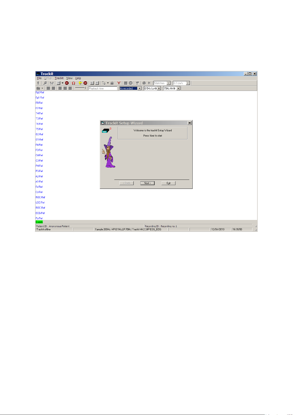
Trackit Mk3 User Manual
Appendix 7: Trackit Setup Wizard
There is a Setup Wizard which s ome users may prefer as a simplified setup method. It is enabled
via the Help menu and appears th e next time (and every time, until disabl ed) the Trackit program
is invoked.
The Wizard can be dismissed at any time by using the top right close butt on : s etup and control can
then continue using the normal Tra c kit program. Exit f r om the Wizard exits the program.
87
Page 88

Trackit Mk3 User Manual
Appendix 8: Troubleshooting guide
COM port problems with Bluetooth communication to Trackit Mk3
The COM port is available but is being used by another application.
This could well be th e c ase if an application s uch Microsoft Activ e Synch is installed and polling the
COM port for a Windows CE device. Make sure Connection Mode for Active Synch is s et to Only
When Device is C onnected, and not to Continuous.
Make sure other applications such as virus protection software and personal firewalls (ZoneAlarm)
are not accessin g the COM port while a connection to Trackit is b eing made.
Problems starting the recording
The setup has not been sent correctly
Under Trackit S tatus, in the Control P a nel, check that Acq uire Ready shows Yes . If it is not ready,
acquisition ca nnot begin. This could be caused by incomplete tr a nsmission of th e Trackit setup. Tr y
to adjust the trans mission delay for serial communication in the Trackit software as described
above.
An incorrect setup has been sent
If an incompatible setup has been sen t to the Trackit the mess a g e; “unable to comply” will indicate
that. The usual cause for this is if a T36 or T24P setup has been sent to a Trackit 24: the pres ence
of poly channels resu ltin g in the setup being rejected. If an incorrect setup has been sent, the
Trackit Control P anel will show ‘Ac quire Ready: No’.
The card is not formatted correctly
If the card is not formatted with a correct 16-bit FAT, a recording cannot commence. Format the
flash card usin g the inbuilt Trackit f ormat utility under Ge t Card Info. See ‘Get Card Info’, in
5.5 Advanced Settings.
Caution: do not attempt to do a low-lev e l format, or do a standard format using a SCSI or
USB card reader.
The card is corrupted
Disk corruption can be caused when a flash card is removed from Trackit or the Card reader while
data is being written or accessed.
Trackit: always stop a recording, or if hot swapping wait for the write LED to go out, b efore removing the card.
Card reader: make sure the dev ic e is s to pped, in Card Services, before r emoving the Card. This is
especially important in Win2000 systems using a USB ca r d r eader, where the activity L ED stays on
for several seconds after deleting an old file. If the card is removed when this LED is on, the card will
be corrupted and a reformat will be necessary . Always stop and eject the card using the icon in the
Windows system tray before physic a lly ejecting it.
The card is not inserted correctly
If the flash ca rd is not pushed in far enou g h, the card will not engage th e p ins on the card reader.
‘No CF card present’, in the Status section of the Tr a ckit Control Panel, will evidence this.
88
Page 89

Trackit Mk3 User Manual
File review problems
The card is not formatted in FAT16
When a recording is made on a car d formatted in FAT32 it will appear t o be severely truncated and
most probably unreadable. If you know a recording has a duration of >24 hours bu t it only shows
up as several minutes in review, the m ost likely cause is that the card is not form atted in FAT16.
Notes:
1 This problem does not occur if th e for m a t has been performed us ing the inbuilt Tra c kit format
utility.
2 Trackit software detects corru pte d or incorrectly form a tte d cards prior to recording.
89
Page 90

Trackit Mk3 User Manual
Accessory name
Type
Length
Manufacturer
Aux. Connector c a ble
Shielded
1 m
Shielded cable
Appendix 9: Manufacturer’s Declaration
EMC Compatibility
This section contains specific information regarding the device’s compliance with EN 60601-1-2.
Note: Medical electrical equipment needs s pec ia l precautions regarding E M C and needs to be installed and put into service according to the EMC informa tion provided here.
WARNING: The use of accessories, transducers and cables other than those specified,
with the exception of transducers a nd c ables sold by the ma nufacturer of t he equipment
as replacement pa rt s for internal components, may re sult in increased emissions or decreased immunity of the equipme nt.
PCU cable 32ch IEEE 1284 C-C
shielded
RJ45 cable Cat 5 UTP Patch Cable 2 m Cat 5 UTP Patch Cable
Input electrodes EEG disc electrodes 1 m Unshielded EEG disc
WARNING: The e quipment or system sh ould not be used adja c ent to or stacked wi th
other equipment and that if adjace n t or st a cked use is necessary, the equi pment or system should be observed to verif y n orma l operation in the c onfiguration i n which it will be
used.
1 m Shielded IEEE 1284 C-
C cable
electrodes
90
Page 91

Trackit Mk3 User Manual
Emissions Test
Compliance
Electromagnetic Environment Guidance
in nearby electronic equipment.
CISPR11/EN55011
EN 61000-3-2
EN 61000-3-3
Test Level
EN 61000-4-4
mode
recommended that the Trackit be powered
EN 61000-4-8
acteristic of a typical location in a
ment
Guidance and Manufacturer’s Declaration
Electromagnetic Emissions
EN 60601-1-2
The Trackit Mk3 is intended for use in the electromagnetic environm ent specified below. The customer or user of the Trackit should as s ure that it is used in su c h a n e nvironment.
RF emissions
CISPR11/EN55011
RF emissions
Harmonic emissions
Voltage fluctuations/
Flicker emissions
Group 1 The Trackit uses RF energy only for its internal function. Therefore, its
Class B The Trackit is suitable for use in all establis hment s , inc lu ding d omest ic
Class A
Complies
Immunity Tes t EN 60601-1-2
Electrostatic discharges
(ESD)
EN 61000-4-2
Electrical fast Transients/burst
Surge
EN 61000-4-5
+/- 6 kV:Contact
+/- 8 kV:Air
+/- 2 kV:AC mains
+/- 1 kV:Signal lines
+/- 2 kV:Common mode
+/- 1kV:Differential
mode
RF emissions are very low and are not likely to cause any interference
establishments an d those direct ly connecte d to the pub lic lo w vo lta ge
power supply net work that supplie s buildings used for d omestic purposes.
Compliance Level E le ctromagnetic Environment Guidance
+/- 6 kV:Contact
+/- 8 kV:Air
+/- 2 kV:AC mains
+/- 1 kV:Signal lines
+/- 2 kV:Common
mode
+/- 1kV:Differential
Floors should be woo d, concrete or ceramic
tile. If floors are covered with synthetic material, the relative humidity should be at least
30%
Mains p ower should b e that o f a typical commercial and/or hospital environment
Mains p ower should b e that o f a typical commercial and/or hospital environment
Voltage dips,short interruptions and voltage
variations on power
supply input lines
EN 61000-4-11
Power frequency
(50/60 Hz) magnetic
field
<5% 230 V
(>95% dip in 230 V) for
0.5 cycle
40% 230 V
(60% dip in 230 V)
for 5 cycle s
70% 230 V
(30% dip in 230 V)
for 25 cycles
<5% 230 V
(>95% dip in 230 V) for
5 sec
3 A/m 3 A/m Power frequency magneti c field s should be a t
<5% 230 V
(>95% dip in 230 V)
for 0.5 cycle
40% 230 V
(60% dip in 230 V)
for 5 cycle s
70% 230 V
(30% dip in 230 V)
for 25 cycles
<5% 230 V
(>95% dip in 230 V)
for 5 sec
Mains p ower should b e that o f a typical commercia l and/or h ospital env ironment . If the
user of the Trackit requires continued operation dur ing power mains interruption s, it is
from an uninterruptible power supply or a
battery
levels char
typica l commercia l and/or hos pital environ-
91
Page 92

Trackit Mk3 User Manual
Note: using unshielded input leads c
Note: using unshielded input leads d
from structures, objects and people.
Immunity Tes t EN 60601 Test Level Compliance Level Electromagnetic Environment Guidance
Portable and mobile RF communications
equipment should be used no closer to any
part of the Trackit, including cables than the
recommended separation distance calculated
from the equation applicable to the frequency
of the transmitter.
Recommended separation distance
RF Common mode/
Conducted Susceptibility
EN 61000-4-6
Radiated RF Electromagnetic Fields
EN 61000-4-3
3 Vrms
150 kHz to 80 MHz
3 V/m
80 MHz to 2.5 GHz
(a) 0.78 Vrms :
150 – 250 kHz
(b) 3 Vrms :
0.25 – 35 MHz
(c) 1 Vrms :
35 – 80 MHz
(a) 0.15 V/m :
80 – 130 MHz
(b) 0.5 V/m :
130 – 309 MHz
(c) 1 V/m :
309 – 2500 MHz
d=4.5 √P
d=1.2 √P
d=3.5 √P
d=23.3 √P : 80 MHz to 130 MHz
d=7 √P : 130 MHz to 309 MHz
d=3.5 √P : 309 MHz to 800 MHz
d=7 √P : 800 MHz to 2.5 GHz
Where P is the maximum output power rating
of the transmitter in watts (W) a ccording to
the manufacturer and d is the recommended
separation distance in meters (m).
Field strengths from fixed RF transmitters, as
determined by an electromagnetic site sur-
a
vey
, should be less than the compliance level
in each frequency range
b
.
Interference may occur in the vicinity of equipment marked with the following symbol:
NOTE 1. At 80 MHz and 800 MHz, the higher frequency range applies.
NOTE 2. These guidelines may not apply in all situations. Electromagnetic propagation is affected by absorption and reflection
92
Page 93

Trackit Mk3 User Manual
mitter
wise
wise
0.01
0.12
0.12
0.23
0.1
0.38
0.38
0.73
1
1.2
1.2
2.3
10
3.8
3.8
7.3
100
12
12
23
from structures, objects and people.
a
Field strength from fixed transmitters, such as base stations for radio (cellular/cordless) telephones and land mobile radios,
amateur radio, AM and FM radio broadcast and TV broadcast cannot be predicted theoretically with accuracy. To assess the
electromagnetic environment due to fixed RF transmitters , an el ectromagnetic site survey should b e consi dered. If the measured field strength in the location in which the Trackit is used exceeds t h e applicable RF compliance level above, t h e Tr ackit
should be observed to verify no rmal o peration. If abnormal performance i s observed, additional measures m ay be nec ess a ry,
such as re-orienting or relocating the Trackit.
b
Over the frequency range 150 kHz to 80 MHz, field strengths should be less than 3 V/m.
c
The immunity levels for conducted RF are for unscreened input electrode leads 1 m in length and worse-case coupling, including any resonances across the frequency band. The interference is less when the coupling plane of the interference
source is not in the same plane as the electrode leads.
d
The immunity levels for radiated RF are for unscreened input electrode leads 1 m in length and worse-case coupling, including any resonances across the frequency band. The interference is less when the polarisation plane of the interference source
is not in the same plane as the electrode leads .
The Trackit Mk3 is intended for use in the electr om agnetic environment in which radiated RF disturbances are c ontrolled. The cu s tom e r or the user of the Trackit Mk3 can help prevent electromagnetic interference by m a intaining a minim um distance between p or ta ble and mobile RF com m unications equipment ( transmitters) and the Trackit Mk3 as recommended below, according to the maximum output power of the communications equipment.
Rated maximum out-
put power of trans-
Separation distance according to frequency of transmitter
m
W 150 kHz to 80 MHz
d=1.2√P at 3 Vrms
d=(3.5/V1)√P other-
For transmitters rated at a maximum output power not listed above, the recommended separation distance d in meters (m)
can be estimated using the equation applicable to the frequency of the transmitter, where P is the maximum output power
rating of the transmitter in watts (W) according to the transmitter manufacturer.
NOTE 1. At 80 MHz and 800 MHz, the separation distance for the higher frequency range applies.
NOTE 2. These guidelines may not apply in all situations. Electromagnetic propagation is affected by absorption and reflection
80 MHz to 800 MHz
d=3.5√P at 3 V/m
d=(3.5/E1)√P other-
800 MHz to 2.5 GHz
d=2.3√P at 3 V/m
d=(7/E1)√P o t herwis e
93
 Loading...