


T240
Autotransformer
Installation and Operation Guide
ã2000 Trace Engineering |
P/N 975-0002-01-02 Rev. B 04/00 |

©2000 Trace Engineering

|
T240 Autotransformer |
|
|
Table of Contents |
|
Section |
Description |
Page |
1. |
INTRODUCTION ..................................................................... |
1 |
|
The T240 Autotransformer .................................................. |
1 |
2. |
INSTALLATION ....................................................................... |
2 |
|
Installation ........................................................................... |
2 |
|
Required Tools ................................................................ |
2 |
|
Mounting ......................................................................... |
2 |
|
Wiring .................................................................................. |
4 |
|
Service Crimps ................................................................ |
4 |
|
Connection Points ........................................................... |
5 |
|
Step-up Configuration ..................................................... |
8 |
|
Deep Well Pump Wiring .................................................. |
9 |
|
Step-Down Configuration .............................................. |
10 |
|
Step-Down Connection of Stacked-pair Inverters ......... |
11 |
|
Generator Output Balancing Autotransformer .............. |
12 |
|
Single 120 volt AC Load ........................................... |
12 |
|
Dual 120 volt AC Loads ............................................ |
13 |
|
Optional Circuit Breakers .............................................. |
16 |
|
Wiring Check ................................................................. |
17 |
3. |
OPERATION ......................................................................... |
18 |
4. |
SERVICE INFORMATION .................................................... |
19 |
5. |
SPECIFICATIONS ................................................................ |
20 |
6. |
WARRANTY .......................................................................... |
21 |
©2000 Trace Engineering |
i |

IMPORTANT SAFETY INSTRUCTIONS
This manual contains important safety instructions that should be followed during the installation and maintenance of this product.
To reduce the risk of electrical shock, and to ensure the safe installation and operation of this product, the following safety symbols have been placed throughout this manual to indicate dangerous conditions and important safety instructions.
WARNING - A dangerous voltage or condition exists in this area. Use extreme caution when performing these tasks.
AVERTISSEMENT - Une tension ou condition dangereuse existe dans cette zone.
Faire preuve d’extrême prudence lors de la réalisation de ces tâches.
CAUTION - This procedure is critical to the safe installation or operation of the unit. Follow these instructions closely.
ATTENTION - Cette procédure est essentielle à l’installation ou l’utilisation de l’unité en toute sécurité. Suivre ces instructions de près.
NOTE - This statement is important. Follow instructions closely.
NOTE - Cette déclaration est importante. Suivre les instructions de près.
•All electrical work must be done in accordance with local, national, and/or international electrical codes.
•Before installing or using this device, read all instructions and cautionary markings located in the T240 and the manual.
•Do not expose this unit to rain, snow or liquids of any type. This product is designed only for indoor mounting.
•To reduce the chance of short-circuits when installing or working with this product, use insulated tools.
•Remove all jewelry such as rings, bracelets, necklaces, etc., while installing this system. This will greatly reduce the chance of accidental exposure to live circuits.
ii |
©2000 Trace Engineering |

•This product contains no user-serviceable parts. Do not attempt to repair this unit.
•Do not mount this device in unventilated enclosures or in an engine compartment.
•Protect the device from splashing when used in vehicular applications.
•To reduce risk of electric shock, disconnect all wiring before attempting any maintenance or cleaning.
•Additional AC disconnects may be required as part of the system installation. Consult local and national electrical code requirements.
•Over-current Protection, provided by a 25 amp circuit breaker, protects the AC input/output wiring. This circuit breaker is branch circuit rated and has a 10,000 AIC rating, suitable for residential and commercial applications.
•This unit is designed to be horizontally wall mounted.
•The AC input and output neutral conductors are not connected (bonded) to the chassis.
•The AC input and output HOT conductor are not isolated from each other.
•The chassis housing of the T240 must be connected to a permanent grounding system as required by the National Electric Code, ANSI/NFPA 701996. This is the responsibility of the system installer. A grounding terminal strip is provided for connection of equipment grounding conductors.
•UL rated as an indoor enclosure.
•UL listed for sale in the U.S. and Canada under Photovoltaic Power System Accessaries (UL1741) and Canadian standard for general use power supplies (CSA C22.2 No. 107.1-95).
SAVE THESE INSTRUCTIONS
©2000 Trace Engineering |
iii |

Disclaimer of Liability
Since the use of this manual and the conditions or methods of installation, operation, use and maintenance of the unit are beyond the control of Trace Engineering, the Company does not assume responsibility and expressly disclaims liability for loss, damage, or expense arising out of or any way connected with such installation, operation, use, or maintenance.
iv |
©2000 Trace Engineering |
1.0 INTRODUCTION
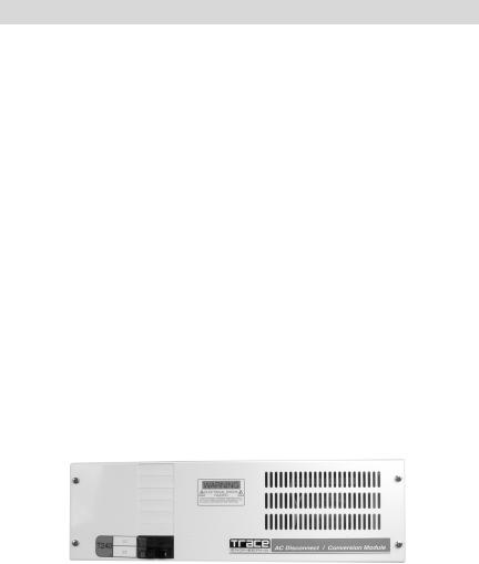
The T240 Autotransformer is designed to step-up 120 volt AC to 240 volt AC or to step-down 240 volt AC into two 120 volt AC circuits. The T240 contains two identical windings that can be used to step-up, step-down, or balance the output voltage of an AC power source (such as an inverter, generator or conventional AC source) to an AC load. The unit is sized to take advantage of Trace Engineering’s inverter/charger line. The exceptionally high efficiency of the T240 Autotransformer makes it ideal for voltage conversion from an inverter, generator or conventional AC source.
The T240 Autotransformer utilizes a highly-efficiency transformer constructed of high temperature materials and M-6 grade steel laminations, meeting UL Class-H standards.
The unit is housed in a powder coated, steel enclosure, suitable for indoor installations and contains knockouts for 3/4 inch and 1 inch conduit connections and additional breakers. One 25 amp dual breaker is supplied with the T240. Up to six additional Square D QOU breakers can be added for additional input/ output wiring protection and control.
Figure 1
T240 Autotransformer
©2000 Trace Engineering |
1 |
2.0 INSTALLATION
Installation
Required Tools
•Wire strippers
•Phillips screw driver
•Slotted screw driver
•Torque wrench
Mounting
Place the T240 Autotransformer in a convenient location, close to the input source (inverter, generator or utility). The T240 must be mounted horizontally on a flat surface (such as a wall) in a clean, dry environment. Do not mount the autotransformer where it will be exposed to the weather or in a wet location.
NOTE: The T240 weighs approximately 50 pounds. Use appropriate wall anchors or backing material (plywood, 2 x 4’s, etc.) that will support its weight.
Procedure:
•Use a level and mark the location for mounting the unit on the wall.
•Measure out the four mounting screw holes according to Figure 3.
•Drill out the mounting holes using a #18 (0.170 inch) drill bit.
•Remove the front cover of the autotransformer by removing the four Phillips screws. Do not lose the screws!
•Use a #10 x 3/8 (or 1/2) inch long screw and washer (and appropriate anchors if necessary) and mount the autotransformer securely to the wall or backing material (plywood, 2 x 4’s, etc.).
•Remove the appropriate knockouts for the conduit. Install the conduit between the autotransformer and input source (inverter, generator, etc.) and output to load. Use separate conduit for input and output wiring.
|
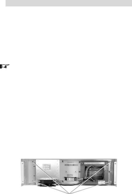
Mounting Holes |
|
Figure 2 |
|
Mounting Holes |
2 |
©2000 Trace Engineering |

2.0 INSTALLATION
|
|
|
|
|
Installation Drawing
Figure 3
|
|
|
|
|
|
|
|
|
|
|
|
|
|
|
|
|
|
|
|
|
|
|
|
|
|
©2000 Trace Engineering |
3 |

2.0 INSTALLATION
Wiring
WARNING: WIRING SHOULD BE PERFORMED ONLY BY QUALIFIED PERSONS.
WARNING: BEFORE WIRING THE AUTOTRANSFORMER, ENSURE THAT ALL SOURCES OF POWER ARE DISCONNECTED. NEVER WORK ON A LIVE CIRCUIT.
CAUTION: THE CONFIGURATION OF THE AUTOTRANSFORMER IS FOR STEP-UP, STEP-DOWN OR CURRENT BALANCING. IT DOES NOT PROVIDE ISOLATION BETWEEN INPUT AND OUTPUT. DO NOT USE THE AUTOTRANSFORMER AS AN ISOLATION DEVICE.
NOTE: All source connections (inverter, generator or utility) are connected to the left-hand side of the installed circuit breaker (see illustrations). All loads connect to the service crimp on the right-hand side of the breaker.
Service Crimps
The service crimps provide a convenient means to connect the autotransformer. Do not use the screw terminals on the breakers for making connections. Do not remove factory wiring.
•Pull back the insulation on the TRANSFORMER wire so it is exposed inside the service crimp.
•Strip off approximately 1/2 inch of the insulation from the wire to be installed and insert the bare wire into the crimp.
•Slide the crimp up to the circuit breaker terminal as far as it will go.
•Place the wire in the crimp and ensure the existing wire’s insulation is fully exposed. Torque the crimp screw to 45 inch/pounds.
•After torquing, ensure the service crimp is tight on both wires and is not able to twist or be moved.
CAUTION: UNUSED SERVICE CRIMPS SHOULD BE TIGHTENED TO THE EXISTING WIRE AND TAPED, SO IT CAN NOT SHORT TO OTHER TERMINALS OR THE CASE.
Breaker Lug |
Service Crimp |
Added
LOAD
Wire
|
|
|
|
Existing Factory Wiring |
|
|
|
975-C00-004 |
|
Figure 4 |
|
|
Installation Drawing |
|
4 |
|
©2000 Trace Engineering |
 Loading...