


Page 1 of 20
THE ULTIMATE IN
REALTIME WIRELESS HD-VIDEO
ENGLISH
Version: 1.0
Made in Germany
WWW.MODUL-NO-1.DE
OPERATING INSTRUCTION

Page 2 of 20
THANK YOU,
for choosing MODUL NO.1!
Please read this manual carefully and make sure that you understand
everything before installing and using the device.
MODUL NO.1 is a powerful, wireless HD-SDI transmission device using the 5GHz band allowing you to
transmit Full HD-Video data, uncompressed up to 1080p60 and 4:2:2 sampling, frame synchronous.
MODUL NO.1 Transmitter (TX) is equipped with a loop-through 3G-SDI input/output. Transmitted video
and audio can be received by up to 4 different Receivers (RX), offered by Multicast version. MODUL
NO.1 is a powerful, lightweight device not requiring a fan, offering optimal integrated multi-antenna
system which uses all kind of reflections and therefore works properly even without line of sight. Receiver
(RX) interface includes two 3G-SDI outputs.
Manufacturer contact:
TQ-Systems Durach GmbH
Johann-Georg-Halske-Strasse 1
87471 Durach
Germany
Tel.: +49 831 690 683
E-Mail: wirelessVideo@tqs.de
WWW.MODUL-NO-1.DE

Page 3 of 20
Content
1 Directions for use .................................................................................................................................. 4
1.1 Symbol descriptions ..................................................................................................................... 4
1.2 Copyrights and property rights ..................................................................................................... 4
1.3 Disclaimer ..................................................................................................................................... 5
1.4 Warranty & Service ....................................................................................................................... 5
2 Safety Instructions ................................................................................................................................. 6
3 Compliance with FCC guidelines .......................................................................................................... 7
4 General information on MODUL NO.1 .................................................................................................. 7
4.1 Product versions ........................................................................................................................... 8
4.2 Scope of supply ............................................................................................................................ 9
4.3 Checklist components ................................................................................................................ 10
4.4 Technical Data ............................................................................................................................ 11
4.4.1 Cable connection Transmitter (TX) / Receiver (RX) ............................................................... 11
4.5 Part designation .......................................................................................................................... 12
5 Set into operation ................................................................................................................................ 13
5.1 Connecting Transmitter (TX) and Receiver (RX) ....................................................................... 13
5.1.1 Connecting Transmitter .......................................................................................................... 13
5.1.2 Connecting Receiver .............................................................................................................. 13
5.1.3 System Start-up ...................................................................................................................... 13
5.2 Channel Programming ................................................................................................................ 14
5.3 Pairing – Channel Storing ........................................................................................................... 14
5.4 Transmission Range ................................................................................................................... 14
5.5 Error-handling ............................................................................................................................. 15
5.5.1 Error Codes ............................................................................................................................ 16
5.6 System Reset ............................................................................................................................. 19
6 Waste Disposal ................................................................................................................................... 19

Page 4 of 20
1 Directions for use
Observance of these Operating Instructions will help you to avoid danger, reduce repair costs and
downtime as well as to increase reliability and the service life MODUL NO.1.
1.1 Symbol descriptions
ATTENTION!
… Indicates a possible hazardous situation that can lead to damage to goods and personal, if
they are not prevented.
NOTE!
… Highlights useful information and recommendations as well as information for efficient and
failure-free operation.
DISPOSAL INFORMATION!
1.2 Copyrights and property rights
This Operating Instruction contains information which is only meant for the purchasers of MODUL NO.1.
The content of this manual is property of TQ-Systems Durach GmbH.
As long as there is no explicit permission from TQ-Systems Durach GmbH this Operating Instruction is
only intended for the operation or maintenance of MODUL NO.1.
Content and works published in this manual are subject to German copyright law. Copying, processing,
distributing and any kind of use outside the limits of copyright law require the written approval of the
particular author, respectively compiler TQ-Systems Durach GmbH.

Page 5 of 20
1.3 Disclaimer
Prior to use please check the video data transmitted. Manufacturer does not accept any liability caused
by incorrect transmission of video data.
All data and notes in these Operating Instructions were prepared with consideration to the statutory
standards and regulations, the present state of technology, as well as our many years of knowledge and
experience.
The manufacturer accepts no liability for damage caused because of:
Non-compliance with the Operating Instructions
Non-specified use
Use of untrained personnel
Arbitrary modification
Technical changes
Use of uncertified spare parts
The actual scope of delivery can, by special designs, deviate from the explanations and presentations
given here, because of the utilization of additional order options, or because of the most recent
technical changes. The responsibilities agreed in the delivery contract, the General Terms and Conditions
as well as the delivery conditions of the manufacturer and the statutory regulations valid at the time of the
conclusion of the contract are effective. We reserve the right to make alterations and modifications within
the framework of legal provisions, as well as changes aimed at improving product quality.
1.4 Warranty & Service
Warranty period for MODUL NO.1 is one year after purchase.
Warranty will be voided within the warranty period, by MODUL NO.1 by any unauthorized repair attempts,
by opening the housing, improper use, damage caused by failure to observe the operating instructions or
by improper use or other external influences leading to product damage, malfunction or damage due to
excess or deficiency of power or short circuit of power, fluid immersion, physical damages caused by
careless handling, dropping or vibration, When any assistance is required, please contact your authorized
dealer or TQ-Systems Durach GmbH via: WirelessVideo@tqs.de. Furthermore, our employees are
always interested in new information and experience arising from use, valuable for the improvement of
our products.

Page 6 of 20
2 Safety Instructions
To ensure your own personal safety and to avoid personal injury (including death) caused by fire
or strong heat, release of chemicals and smoke emission, product- or material damage, you
necessarily must read, understand and follow the following safety instructions. Use the product properly.
Before using an external power supply, always check that the voltage is within the specified
range and that the polarity of the connector is correct, as this will avoid smoke or fire.
Do not attempt to disassemble, modify or repair this product yourself. That may cause fire or
electric shock. Please refer inspection and repair services to your dealer or TQ-Systems Durach.
Do not use this product near water or in high humidity environments. This may cause fire or
electric shock. .
In case of damage, smoke, unusual smell or other unexpected situations, stop use immediately
and consult your dealer or TQ-Systems Durach GmbH
Turn off the power immediately if any, liquid or substance gets inside the product. Continuous use
under such condition may cause shortage, fire or electric shock.
Before touching please take note that during operation the casing may heat-up. However Velcro
can be used.
Do not stare at LED lights on the side panel of the MODUL NO.1, as this may cause damage to
the eyes.
Do not place this product on an uneven surface or one with vibration. It may cause failure or
damage.
Always ensure that the system is mounted properly.
MODUL NO.1 is designed not to exceed the limits for exposure to radio waves recommended by
international guidelines and include safety margins designed to assure the protection of all persons,
regardless of age and health. During a longer operation a minimum distance between product and
operator`s head of 20cm is recommended. This product is approved for technical standard compliance
certification as a wireless device of radio stations with low antenna specified under international and U.S.
FCC radio wave regulations. Therefore a license for radio station use is not required to operate this
product. MODUL NO.1 uses 5GHz band.

Page 7 of 20
3 Compliance with FCC guidelines
This device has been tested and found to comply with the limits for a Class A digital device, pursuant to
Part 15 of the FCC Rules.
Operation of this device is subject to the following two conditions:
this device may not cause interference
this device must be fail-safe against all interference to which it is exposed, including that which
could impact the operation of the device.
This equipment generates, uses and can radiate radio frequency energy and, if not installed and used in
accordance with the instructions, may cause harmful interference to radio reception. However, there is no
guarantee that interference will not occur in a particular installation.
This equipment complies with FCC radiation exposure limits set forth for an uncontrolled environment
During the installation and utilization of this device, please ensure that there is a distance of at least 20
cm between the device and your body
Changes or modifications to this unit not expressly approved by the party responsible for compliance
could void the user's authority to operate the equipment.
The device may only be used within the permitted radiation according to part 15 of FCC rules. Any kind of
modification that lead to frequency range outside the authorized frequency band is strictly forbidden and
will lead to legal consequences.
4 General information on MODUL NO.1
MODUL NO.1 transmits uncompressed FULL HD-Video data up to 1080p60 and 4:2:2 sampling. The
transmitter broadcasts its input signal to the receiver without frame delay using 5GHz frequency band.
MODUL NO. Transmitter (TX) is equipped with a loop-through 3G-SDI input/output. Transmitted video
and audio can be received by up to 4 different Receivers (RX) and a range of 100m line of sight. Without
line of sight range differs according to obstacles, like walls of reinforced concrete, steel buildings, or
structures which may attenuate the signal and decreases the transmission distance.
MODUL NO.1 is a powerful, lightweight device not requiring a fan, offering optimal integrated multiantenna system which uses all kind of reflections and therefore works properly even without line of sight.
Receiver (RX) interface includes two 3G-SDI outputs. Transmitter (TX) is directly connected to a camera
or other video data source via SDI-cable. Receiver can be connected with different displays or recorders
via SDI-cable.

Page 8 of 20
4.1 Product versions
MODUL NO.1 comes in two versions: Unicast (UC) and Multicast (MC). Unicast (UC) transmits video
data to only one dedicated Receiver (RX). The Transmitter (TX) of this version cannot serve more than
one Receiver (RX) simultaneously. The Multicast (MC) version transmits video and audio data up to four
Receivers (RX) simultaneously. Whereby all transmission lines are 128-bit encrypted.
Unicast (UC):
Multicast (MC):
Transmitter (TX)
Transmitter (TX)
Receiver (RX)
Receiver (RX) 1
Receiver (RX) 2
Receiver (RX) 3
Receiver (RX) 4

Page 9 of 20
4.2 Scope of supply
MODUL NO.1 is supplied in a special transportation- and storage case. Additional Receivers (RX) for
Multicast (MC) enlargement are supplied in standard sales packaging. Components supplied depend on
type of version:
Article number
Description
Components
Pieces
TQD:F0001-X-1
Modul No.1 /SDI Wireless HD
Video Unicast Set:
Transmitter (1x) / Receiver (1x)
Transmitter (Transmitter TX)
1
Receiver (Receiver RX)
1
Adapter cable
2
Ferrite for SDI-cable
2
Operating Instructions (german / english)
1
TQD:F0001-X-2
Modul No.1 MC /SDI Wireless
HD Video
Multicast Set:
Transmitter (1x) / Receiver (1x)
Transmitter (Transmitter TX)
1
Receiver (Receiver RX)
1
Adapter cable
2
Ferrite for SDI-cable
2
Operating Instructions (german / english)
1
TQD:F0001-X-3
Modul No.1 MC /SDI 2RX,
Wireless HD Video
Multicast Set:
Transmitter (1x) / Receiver (2x)
Transmitter (Transmitter TX)
1
Receiver (Receiver RX)
2
Adapter cable
3
Ferrite for SDI-cable
3
Operating Instructions (german / english)
1
TQD:F0001-X-4
Modul No.1 MC /SDI 3RX,
Wireless HD Video
Multicast Set:
Transmitter (1x) / Receiver (3x)
Transmitter (Transmitter TX)
1
Receiver (Receiver RX)
3
Adapter cable
4
Ferrite for SDI-cable
4
Operating Instructions (german / english)
1
TQD:F0001-X-5
Modul No.1 MC /SDI 4RX
Wireless HD Video
Multicast Set:
Transmitter (1x) / Receiver (4x)
Transmitter (Transmitter TX)
1
Receiver (Receiver RX)
4
Adapter cable
5
Ferrite for SDI-cable
5
Operating Instructions (german / english)
1
TQD:F0001-X-6
Modul No.1 MC RX /SDI,
Wireless HD Video Receiver
Receiver (Receiver RX)
1
Adapter cable
1
Ferrite for SDI-cable
1
MODUL NO.1 does not include SDI-cable that is necessarily used for operation.

Page 10 of 20
4.3 Checklist components
Transmitter (Transmitter: TX)
Receiver (Receiver: RX)
applicable version is marked:
Unicast (UC) or Multicast (MC)
applicable version is marked:
Unicast (UC) or Multicast (MC)
HR10/ D-Tap Adapter
cable with ferrite,
one each for Transmitter
(TX) and Receiver (RX)
Additional ferrite for SDIcable (75 Ohm), one each for
Transmitter (TX) and Receiver
(RX), fix the ferrite near to
casing
Operating Instructions (german / english)
Please make sure that you do not lose one of the components described above.
Appropriate accessories:
Thread adapter 3/8“ to 1/4"
XLR Adapter cable
SDI-cable in different lengths
Malfunction or product damages caused by incorrect storage, poor maintenance, damage due to
accidents, to negligence, to improper / incorrect usage, self-constructed connection cables or
manipulation by unauthorized personnel will lead to guarantee void.

Page 11 of 20
4.4 Technical Data
Latency
<1ms
Resolution
1080p60; 1080p50;
1080p30/29.97; 1080p25/24.97; 1080p23.98/24;
1080i60/59.94; 1080i50; 1080psf30; 1080psf25; 720p60; 720p50
Audio
embedded
Frequency band
5,180 - bis 5,825GHz
DFS Frequencies
5,270 up to 5,550GHz and 5,670GHz for EU&US
Modulation
OFDM/QAM
Übertragungsmethode
MIMO (multiple in / multiple out) integrated multi-antenna system
Protection class
IP41 / splash protected
Range
Up to 100m LoS
Without line of sight less range due to dampening impact of different
material
Weight
Less than 250g
Display
Signal strength / Selected Transmitter (Channel)
Size
146mm x 117mm x 28mm
Voltage supply
HR10-7P-4S / D-Tap Adapter cable 10,5 V – 36 V DC
Power consumption
5-6 W
Interface
HD 3G-SDI Video
Übertragungsstandard
WHDI
Certification
CE, FCC
Fastening
2 x 3/8“ Thread, optional Velcro
Storage temperature (tested)
-40-85°C at 10%~90% humidity
Operating temperature (tested)
0-40°C at 10%~90% humidity
4.4.1 Cable connection Transmitter (TX) / Receiver (RX)
Cable connection
1.) Use included / authorized power-supply cord
2.) Use locking Hirose (HR10-7P-4S) circular connector to connect the system with camera / battery
/ power supply:
Pin 1: negative (-)
Pin 2: --
Pin 3: -Pin 4: positive (+)
3.) The voltage range is between 10.5V – 36V DC
4.) For Transmitter (TX) BNC jack SDI1 is the SDI input which has to be connected to the SDIoutput of the video source.
5.) For Transmitter (TX) BNC jack SDI2 is the loop through and can be used as output for the
original signals.
6.) For Receiver (RX) BNC Jack SDI1 and SDI2 can be used as output.
Page 12 of 20
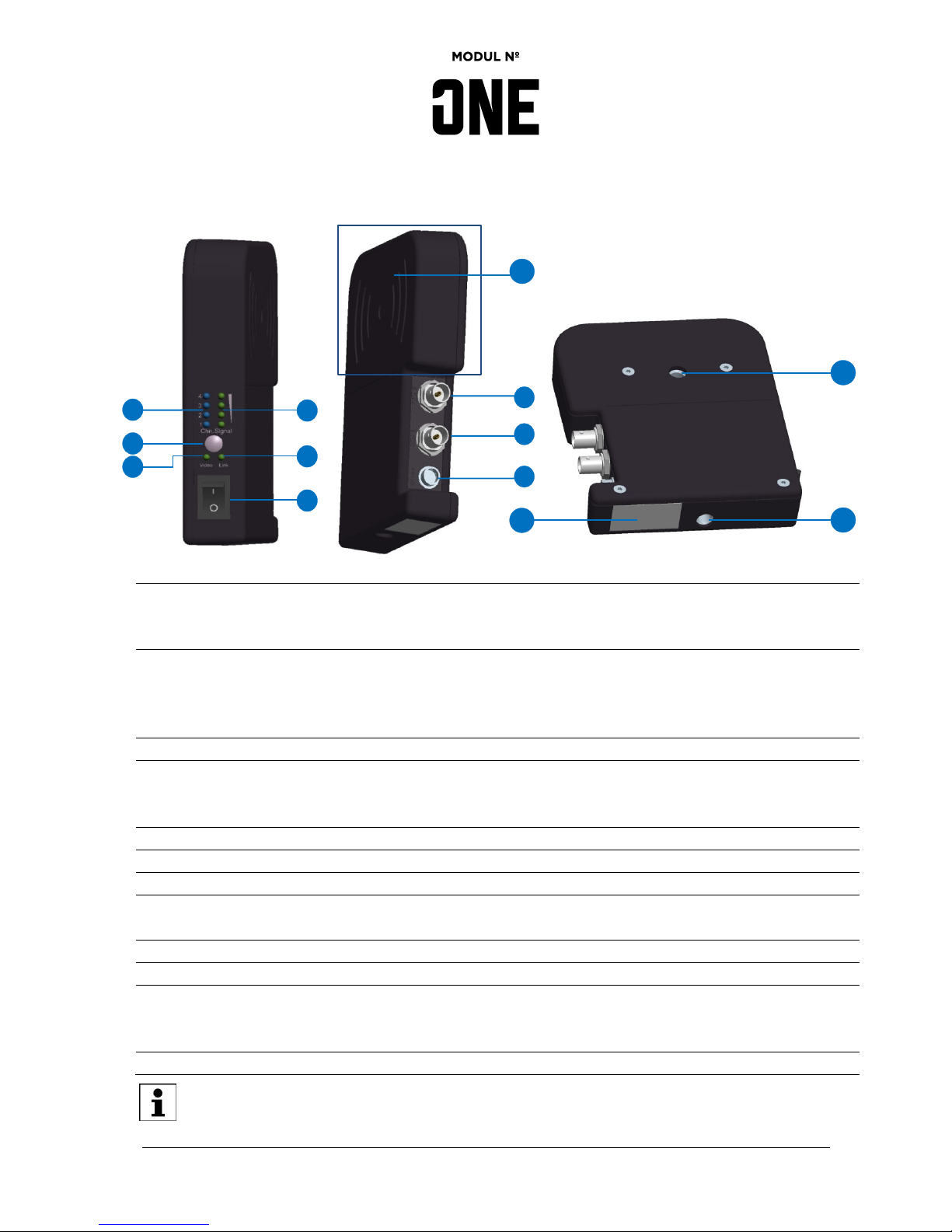
4.5 Part designation
Transmitter (TX) and Receiver (RX)
1
Channel selection
Only for Receiver: The blue LED display shows the selected channel
where Transmitter has been programmed on Receiver prior to use.
Receiver allows programming up to 4 different Transmitter.
2
Selection button
Using the selection button it is possible to change any time between
the memorized channels (presets). Using selection button for system
reset: switch the device on and press the reset button for at least 20
seconds before releasing it again.
3
Video signal LED
If this LED shows green light the input video signal was detected.
4
Signal strength LED
Monitors how strong / stable the signal is. The higher the signal
strength the more green LED lamps will be on. (1 LED poor / 4 LED
best)
5
Field strength display
LED monitors whether Transmitter and Receiver are connected.
6
On/off-switch
O=Off / I=on
7
SDI 2
BNC/SDI output and Loop-through (only Transmitter)
8
SDI 1
BNC/SDI connection for SDI-Input (Transmitter) and SDI-Output
(Receiver)
9
Power Supply
HR10/ D-Tap adapter cable 10,5V-36V DC
10 & 11
3/8“ Thread
Stable mounting at two areas
12
Labelling area
Label identification regarding type of:
Transmitter (TX) or Receiver (RX)
UC for Unicast version and MC for Multicast version
13
Antenna area
This area should not be covered
After two minutes the LED the system will be turned off to avoid irritating light sources while
recording. Press the selection button (2) at any time to reactivate the LEDs.
2
3
1
4 5 6 7 8
9
10
11
12
13

Page 13 of 20
5 Set into operation
Please mount MODUL NO.1 vertically to avoid antenna area is covered.
5.1 Connecting Transmitter (TX) and Receiver (RX)
5.1.1 Connecting Transmitter
1.) Use D-Tap adapter cable to connect Transmitter (TX) and power supply, please make sure that
power supply range is within 10.5V to 36V DC.
2.) Use SDI1-Input to connect Transmitter and video source via SDI-cable.
3.) SDI2 can be used as Loop-through.
5.1.2 Connecting Receiver
1.) Use D-Tap adapter cable to connect Receiver (RX) and power supply, please make sure that
power supply range is within 10.5V to 36V DC.
2.) SDI1 and SDI2 each can be used as output.
5.1.3 System Start-up
1.) Switch the Transmitter on using the on/off switch (6).
2.) Switch the Receiver on using the on/off switch (6).
In delivery state, Transmitter and Receiver are paired and will automatically link after the system
has been started. The Field strength display (5) will blink during connection build-up.
Connection setup is completed. Continuous lit of Field strength display (5) at Transmitter (TX) and
Receiver (RX) indicates the connection has been setup successfully. If a valid video signal is applied it
will be transmit to Receiver (RX).

Page 14 of 20
5.2 Channel Programming
MODUL NO.1 Receiver may store different channels (so called presets) up to four different video
sources. After channel setting you can switch video source using select button (2). To switch between
channels please proceed as follows:
1.) Start set up with Receiver: please press select button (2)
2.) LED (1) indicates current selection
3.) LED of video signal display (3) indicates change by flashing green
4.) After successful connection, status LED of video signal display (3) will continuously lit.
5.3 Pairing – Channel Storing
All MODUL NO.1 sets are paired in delivery status. After System Reset (chapter 5.6), if a different
configuration is needed, or additional Receivers should be connected to extend the multicast set up,
Transmitter (TX) and Receiver (RX) can be pared as follows:
Please note that during pairing the distance between Transmitter (TX) and Receiver (RX) should be at
least 30cm.
1.) Please switch on Transmitter and Receiver using On/off switch (6) and wait at least 30 seconds
until the system is up.
2.) Select channel by pushing select button on Receiver (RX). LED will indicate the selected
channel.
3.) Press the select button for 5 seconds on Transmitter (TX). LED (5) will flash slowly.
4.) Press the select button for 5 seconds on Receiver (RX). At first LED (5) will indicate pairing
process by flashing slowly, if Transmitter (TX) and Receiver (RX) are connected successfully
LED (5) flashes fast.
5.) LED (5) continuously lit if pairing process has been successfully completed successfully.
6.) Transmitter (TX) and Receiver (RX) indicate the same programmed channel.
When power switch is turned on, Transmitter (TX) and Receiver (RX) will start searching for a
frequency that it can be linked to. If there is any disturbance in the chosen frequency the system
will change the link mode automatically. Regarding pairing: Previously executed programming will be
replaced. A programmed channel (preset) cannot be used twice. Both, Transmitter (TX) and Receiver
(RX) must have the same channel selected. Additional Receiver (RX) can be added as described.
5.4 Transmission Range
Transmission range may vary due to environmental circumstances, radio wave conditions, buildings or
weather conditions. Signal reception may vary depending on MODUL NO.1 placement. Optimal alignment
of the system is to place it vertically where the antenna area remains uncovered (see 5.1).

Page 15 of 20
5.5 Error-handling
Error
Cause / source
Solution
No signal given by
Receiver (RX)
Connection between
Transmitter(TX) and
Receiver (RX) may be
interrupted or cannot be set
up properly
1) Check whether LED indication (5) of
field strength continuously lit.
2) Check whether Transmitter (TX) and
Receiver (RX) are paired.
3) Check distance between Transmitter
(TX) and Receiver (RX)
However Transmitter (TX)
and Receiver (RX) are
paired no video data is
transmitted
Cable connection might be
damaged
1) Please check SDI-cable connection.
2) Please check video-signal validity.
Pairing failed
Distance between
Transmitter (TX) and
Receiver (RX) too short.
Vergrößern Sie den Abstand zwischen
Transmitter und Receiver (mindestens
30cm).
Pairing failed
Channel programming
(preset) has been started
with Receiver (RX)
Start pairing with Receiver (RX) and pair
one by one. Simultaneous pairing of
different receiver (RX) is not possible.
Page 16 of 20
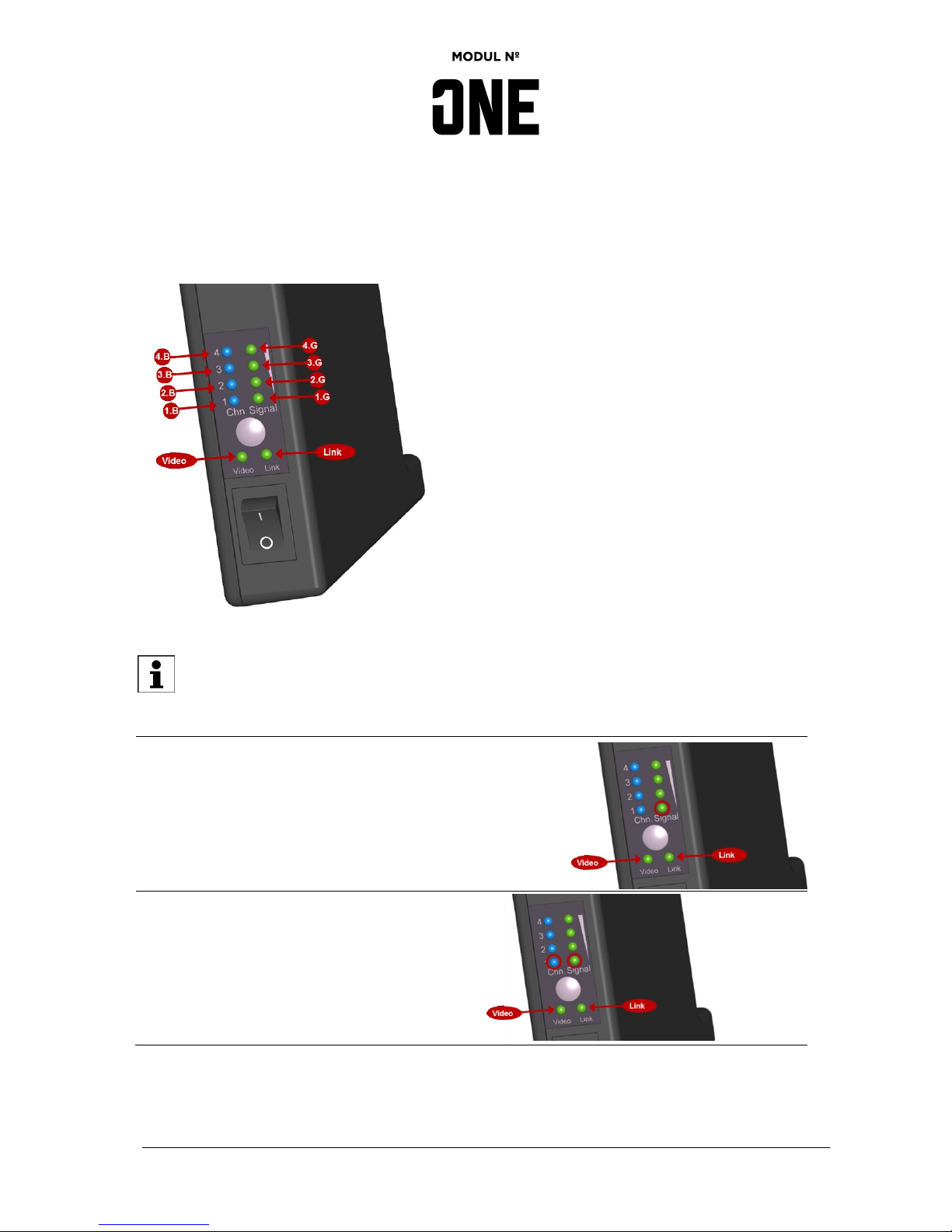
5.5.1 Error Codes
In case of disfunction Video-LED (green) and Link-LED (green) flashes fast. According to current error or
disfunction Channel-LED (blue) and/or Signal-LED (green) lit continuously.
Video-LED and Link-LED flashes fast!
Error Code
Display / Indication
Acknowledgement of pairing failed:
1.G LED (green) lits continuously
Device discovery failed:
1.B LED (blue) and
1.G LED (green) lit continuously

Page 17 of 20
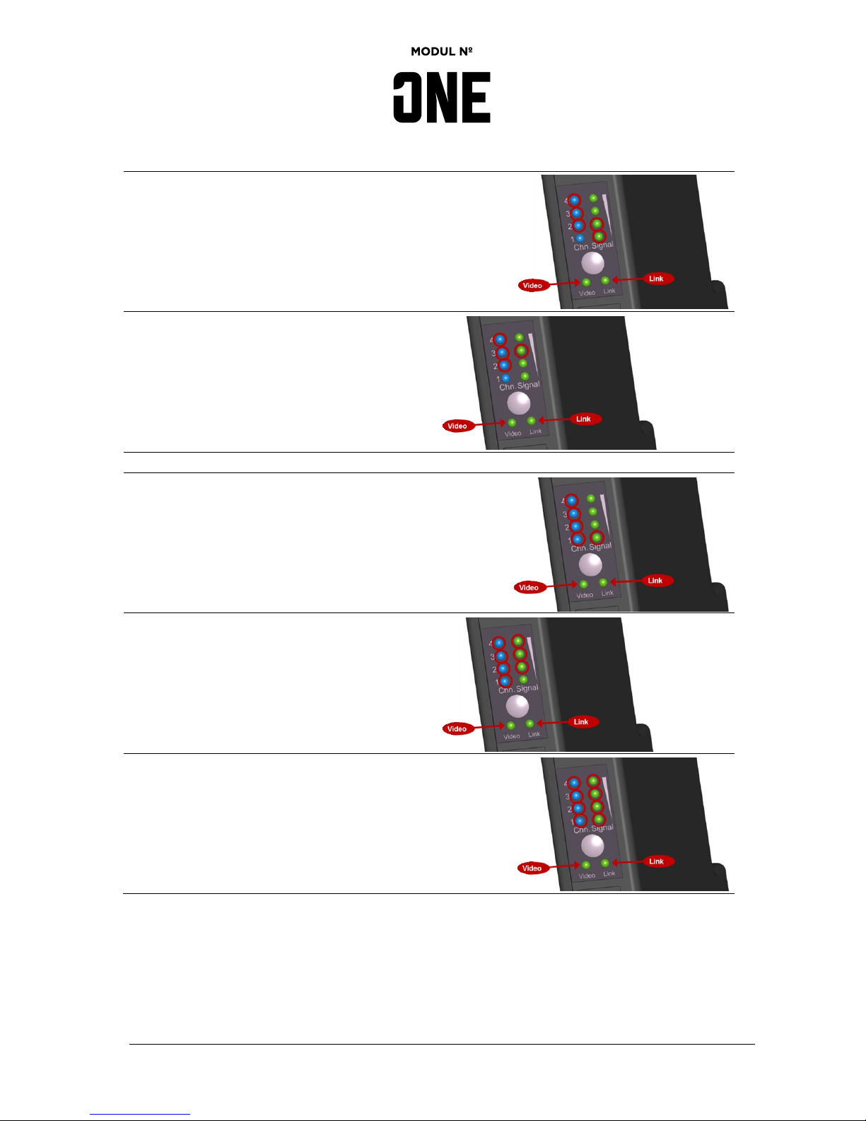
Error Code
Display / Indication
Registration failed:
2.B LED (blue) and
1.G LED (green) lit continuously
Connection attempt failed:
1.B and 2.B LED (blue) and
1.G LED (green) lit continuously
Device disconnection failed:
3.B LED (blue) and
1.G LED (green) lit continuously
Timer error; (re)sheduling virtual timer:
4.B LED (blue) and
1.G LED (green) lit continuously
Function parameter is pointer with no valid
address:
1.B and 4.B LED (blue) and 1.G LED (green) lit
continuously
General initialization error:
2.B, 3.B and 4.B LED (blue) lit continuously
Page 18 of 20
Error Code
Display / Indication
Timers could not be initialized:
2.B, 3.B, 4.B LED (blue) and 1.G, 2.G LED
(green) lit continuously
Memory allocation error:
2.B, 3.B, 4.B LED (blue) and
3.G LED (green) lit continuously
System Error
Function pointer has no valid address:
1.B, 2.B, 3.B, 4.B LED (blue) and 1.G LED
(green) lit continuously
Error handling error code:
1.B, 2.B, 3.B, 4.B LED (blue) and 2.G, 3.G, 4.G
LED (green) lit continuously
Unexpected value of current state:
1.B, 2.B, 3.B, 4.B LED (blue) and 1.G, 2.G, 3.G,
4.G LED (green) lit continuously

Page 19 of 20
5.6 System Reset
To revert to factory settings please follow the instruction below:
1.) Switch on Transmitter (TX) und Receiver (RX) using on/off switch.
2.) Press select button for 20 seconds (2) at Receiver (RX).
3.) Press select button for 20 seconds (2) at Transmitter (TX).
4.) Switch off both, Transmitter (TX) and Receiver (RX).
5.) Switch on both, Transmitter (TX) and Receiver (RX).
Reestablish the connection between Transmitter (TX) and Receiver (RX) by following the
instructions under chapter „5.3 Pairing “
6 Waste Disposal
Only EU (and EEA). The crossed-out refuse container symbol on this product or literature
indicates that it should not be disposed with other business waste at the end of its working life.
The product should be handed in at a designated collection point or to an authorized collection
site for recycling waste electrical and electronic equipment (EEE). Improper handling of this
type of waste could have a possible negative impact on the environment and human health due to
potentially hazardous substances that are generally associated with EEE. At the same time, the correct
disposal of this product will contribute to the effective use of natural resources.
For more information about where to drop waste equipment for recycling, please contact your local city
office, waste authority, approved WEEE scheme or your household waste disposal service.

 Loading...