

Page 1
TO Av¡at¡on
EASA.AP445
KTX2-F.01 00
MAN
KTX2-F.0001
MAN
Operation
Doc.-No.
lssue:
ECR-No.
Date:
MoC:
and lnstallation Manual
KTX2-F.A-MAN
0001
KTX2.F.A-ECR.O204
2019-07-03
0
Document Release
lFunction
Prepared
Checked
by
by
Name
Thomas Wähner
Florian Holzner
Ðate
2019-07-03
2019-07-03
Approved by Thomas Eilers 2019-07-03
KTX2-F.A-MAN.0001.docx
@ TQ-Systems GmÞH.
requ¡res the
pr¡or
wr¡tlen consent
All
¡nformat¡on contained
of TQ-Systems GmbH.
¡n th¡s
documents have to be
treated
conf¡dential. The transfer of
strictly
Signature
/,
iV
presentations
w,1,,-
áz
and know-how to third
Page 1 of74
parties
Page 2

TQ Aviation KTX2-F.0100
EASA.AP445 MAN
KTX2-F.A-MAN.0001.docx Page 2 of 74
© TQ-Systems GmbH. All information contained in this documents have to be treated strictly confidential. The transfer of presentations and know-how to third parties
requires the prior written consent of TQ-Systems GmbH.
Page 3

TQ Aviation KTX2-F.0100
EASA.AP445 MAN
Mode-S Transponder
KTX2-F (flat 160mm format) with ADS-B with Part-No 295153
KTX2-F
Flat (160mm) format
Operation and Installation
Manual
KTX2-F.A-MAN.0001.docx Page 3 of 74
© TQ-Systems GmbH. All information contained in this documents have to be treated strictly confidential. The transfer of presentations and know-how to third parties
requires the prior written consent of TQ-Systems GmbH.
Page 4
TQ Aviation KTX2-F.0100
EASA.AP445 MAN
Revision List
Revision Date Topic
0100 2019-02-07 Initial Release
Service Bulletins (SB)
Service Bulletins must be inserted in the manual and added to this table.
No SB No Rev. Release date Date Added Name
KTX2-F.A-MAN.0001.docx Page 4 of 74
© TQ-Systems GmbH. All information contained in this documents have to be treated strictly confidential. The transfer of presentations and know-how to third parties
requires the prior written consent of TQ-Systems GmbH.
Page 5

TQ Aviation KTX2-F.0100
EASA.AP445 MAN
Change History
Product
Revision
Date Description of Change
KTX2-F.A-MAN.0001.docx Page 5 of 74
© TQ-Systems GmbH. All information contained in this documents have to be treated strictly confidential. The transfer of presentations and know-how to third parties
requires the prior written consent of TQ-Systems GmbH.
Page 6

TQ Aviation KTX2-F.0100
EASA.AP445 MAN
Table of Contents
1. General ..................................................................................................................................... 9
1.1 Purpose ............................................................................................................................. 9
1.2 Scope ................................................................................................................................ 9
1.3 Terminology ....................................................................................................................... 9
1.4 Symbols ............................................................................................................................ 9
1.5 Abbreviations ................................................................................................................... 10
1.6 Customer Support ........................................................................................................... 14
1.7 Features .......................................................................................................................... 15
1.8 Safety-Conscious Utilization ............................................................................................ 16
1.9 Restriction for Use ........................................................................................................... 16
2. Operation ................................................................................................................................ 17
2.1 Controls and Display ....................................................................................................... 17
2.1.1 Controls ....................................................................................................................... 18
2.1.2 Display Indications ....................................................................................................... 19
2.2 Normal Operation Menu Structure ................................................................................... 20
2.2.1 ON/OFF Switching ....................................................................................................... 21
2.2.2 Transponder-Modes .................................................................................................... 22
2.2.3 Squawk Code Change ................................................................................................. 23
2.2.4 VFR – Squawk ............................................................................................................. 24
2.2.5 Squawk Ident (ID, SPI) ................................................................................................ 25
2.2.6 Airborne/Ground Indication .......................................................................................... 25
2.2.7 ADS-B Status Indication .............................................................................................. 27
2.2.8 Adjustable parameters in normal operation mode ........................................................ 28
2.2.9 GNSS Data .................................................................................................................. 30
3. Setup Mode ............................................................................................................................. 31
3.1 Controls and Display ....................................................................................................... 31
3.2 Entering Set Up ............................................................................................................... 33
3.3 Controls ........................................................................................................................... 33
3.3.1 Selection ...................................................................................................................... 33
3.3.2 Return to parent menu ................................................................................................. 33
3.3.3 Cancel/Discard ............................................................................................................ 33
3.4 Setup Menus ................................................................................................................... 34
3.4.1 Brightness ................................................................................................................... 34
3.4.2 Flight-Identifier (Flight ID) ............................................................................................ 37
3.4.3 Modify VFR .................................................................................................................. 47
3.4.4 Factory Reset .............................................................................................................. 49
3.4.5 Test Menu ................................................................................................................... 49
4. Errors, Warnings and Notifications .......................................................................................... 53
4.1 Degrading failures ........................................................................................................... 53
4.1.1 Low Battery Voltage ..................................................................................................... 54
4.1.2 Very Low Battery Voltage ............................................................................................ 55
4.2 Limiting failures ............................................................................................................... 56
4.3 Severe failures ................................................................................................................ 56
4.4 Notifications ..................................................................................................................... 58
4.4.1 GNSS Data CRC Failure ............................................................................................. 58
4.4.2 Do System Restart ....................................................................................................... 58
5. Installation ............................................................................................................................... 59
5.1 Equipment Connections ................................................................................................... 59
5.1.1 Electrical Connections ................................................................................................. 59
5.1.2 Mutual Suppression ..................................................................................................... 59
5.1.3 Ground Switch ............................................................................................................. 59
KTX2-F.A-MAN.0001.docx Page 6 of 74
© TQ-Systems GmbH. All information contained in this documents have to be treated strictly confidential. The transfer of presentations and know-how to third parties
requires the prior written consent of TQ-Systems GmbH.
Page 7

TQ Aviation KTX2-F.0100
EASA.AP445 MAN
5.1.4 Static Air Port ............................................................................................................... 60
5.1.5 GNSS Interface ........................................................................................................... 60
5.1.6 Antenna Connector ...................................................................................................... 60
5.2 Wiring .............................................................................................................................. 64
5.2.1 Conductor Cross Section ............................................................................................. 64
5.2.2 Wiring Scheme ............................................................................................................ 64
6. Drawings ................................................................................................................................. 65
7. Technical Data ........................................................................................................................ 67
7.1 General ........................................................................................................................... 67
7.2 Transmitter – Receiver .................................................................................................... 69
8. FCC related issues .................................................................................................................. 70
8.1 Radiofrequency radiation exposure Information: .............................................................. 70
8.2 Compliance ..................................................................................................................... 70
8.3 Modifications ................................................................................................................... 70
9. Maintenance ........................................................................................................................... 71
9.1 Periodic Maintenance ...................................................................................................... 71
9.2 Repair .............................................................................................................................. 71
9.3 Cleaning .......................................................................................................................... 71
10. EXCLUSIVE LIMITED WARRANTY and LIMITATIONS ON LIABILITY ............................... 72
11. Software License Conformity ............................................................................................... 73
List of Tables
Table 1: Transponder Modes ................................................................................................................. 22
Table 2: GND Switch Support ................................................................................................................ 40
Table 3: Certitified GNSS Units .............................................................................................................. 42
Table 4: Approved GNSS Units .............................................................................................................. 42
Table 5: List of supported GNSS Devices .............................................................................................. 43
Table 6: Degrading Failures ................................................................................................................... 54
Table 7: Severe Failures ........................................................................................................................ 57
Table 8: L-Band Antennas ..................................................................................................................... 61
Table 9: Common Antenna Cables ........................................................................................................ 62
Table 10: Technical Data ....................................................................................................................... 68
Table 11: Transmitter Data .................................................................................................................... 69
Table 12: Receiver Data ........................................................................................................................ 69
Table 13: General Data .......................................................................................................................... 69
List of Figures
Figure 1: Display Diagram ...................................................................................................................... 17
Figure 2: Controls .................................................................................................................................. 18
Figure 3: Indicators ................................................................................................................................ 19
Figure 4: Operational menu structure ..................................................................................................... 20
Figure 5: Initial Display ........................................................................................................................... 21
Figure 6: Normal Operation .................................................................................................................... 22
Figure 7: VFR-Squawk ........................................................................................................................... 24
Figure 8: Squawk Ident .......................................................................................................................... 25
Figure 9: Airborne/Ground Indication "FLY" ........................................................................................... 26
Figure 10: Airborne/Ground Indication "GND" ........................................................................................ 26
Figure 11: ADS-B Indication ................................................................................................................... 27
Figure 12: Change Flight ID ................................................................................................................... 28
Figure 13: Change Brightness................................................................................................................ 28
Figure 14: GNSS Data Display ............................................................................................................... 30
Figure 15: Button functions in Setup Mode............................................................................................. 31
KTX2-F.A-MAN.0001.docx Page 7 of 74
© TQ-Systems GmbH. All information contained in this documents have to be treated strictly confidential. The transfer of presentations and know-how to third parties
requires the prior written consent of TQ-Systems GmbH.
Page 8

TQ Aviation KTX2-F.0100
EASA.AP445 MAN
Figure 16: Setup mode menu structure .................................................................................................. 32
Figure 17: Setup Menu 1 ........................................................................................................................ 33
Figure 18: Setup Menu 2 ........................................................................................................................ 33
Figure 19: Setup Brightness Menu ......................................................................................................... 34
Figure 20: Button Illumination Mode "Off"............................................................................................... 35
Figure 21: Button Illumination Mode "On"............................................................................................... 35
Figure 22: Button Illumination Mode "Auto" ............................................................................................ 36
Figure 23: Flight ID configuration ........................................................................................................... 37
Figure 24: FID Limitation Notification ..................................................................................................... 37
Figure 25: Flight ID Edit Menu ................................................................................................................ 38
Figure 26: Device Parameter Configuration Menu.................................................................................. 39
Figure 27: Aircraft Category Selection Menu .......................................................................................... 40
Figure 28: Ground Switch Setup Menu .................................................................................................. 40
Figure 29: Maximum Speed Category Selection Menu........................................................................... 41
Figure 30: GNSS Device Selection Menu .............................................................................................. 42
Figure 31: Baud Rate Selection Menu .................................................................................................... 43
Figure 32: Aircraft Length/Width Configuration Menu ............................................................................. 44
Figure 33: GNSS Antenna Offset Configuration Menu ........................................................................... 45
Figure 34: Delete Flight ID Menu ........................................................................................................... 46
Figure 35: Multiple Flight ID Selection Menu .......................................................................................... 47
Figure 36: Modify VFR Code Menu ........................................................................................................ 47
Figure 37: Factory Reset Menu .............................................................................................................. 49
Figure 38: Test Menu ............................................................................................................................. 49
Figure 39: Altitude Offset Calibration Menu ............................................................................................ 50
Figure 40: Test Mode Menu ................................................................................................................... 51
Figure 41: Device Info Menu .................................................................................................................. 52
Figure 42: Low Battery Voltage .............................................................................................................. 54
Figure 43: Very Low Battery Voltage ...................................................................................................... 55
Figure 44: Missing AA-Code .................................................................................................................. 56
Figure 45: Critical Error (Example) ......................................................................................................... 56
Figure 46: GNSS CRC Failure ............................................................................................................... 58
Figure 47: System Restart ..................................................................................................................... 58
Figure 48: Wiring.................................................................................................................................... 64
Figure 49: Dimensions of KTX2-F Standard round format ...................................................................... 65
Figure 50: Panel Cut-Out ....................................................................................................................... 66
KTX2-F.A-MAN.0001.docx Page 8 of 74
© TQ-Systems GmbH. All information contained in this documents have to be treated strictly confidential. The transfer of presentations and know-how to third parties
requires the prior written consent of TQ-Systems GmbH.
Page 9
TQ Aviation KTX2-F.0100
EASA.AP445 MAN
1. General
1.1 Purpose
This manual contains information about the physical, mechanical and electrical characteristics,
installation and operation for the KTX2-F Mode S Transponder. Additionally it describes the ADS-B
functionality for a compliant ADS-B Out installation using Extended Squitter (ES).
1.2 Scope
This manual applies to the operation and installation of the KTX2-F Mode S Transponder.
At the publication date of this manual the software version is 0100 and the FPGA version is 0042. The
software and FPGA versions are subject to change without further notice.
1.3 Terminology
Except where specifically noted, references made to “the Unit” or “the Installation” will apply to the
transponder defined in 1.2.
Referenced Documents where the respective document is identified by document number, document
title and issue.
•
The word MUST in the text denotes a mandatory instruction. A deviation is not permissible.
•
The word SHOULD in the text denotes a recommendation or advice. Such recommendations or
advice is expected to be followed unless good reasons are stated for not doing so.
•
The word MAY in the text denotes a permissible practice or action.
Note: Background information contained in this document is always indicated by using an italic character
font.
1.4 Symbols
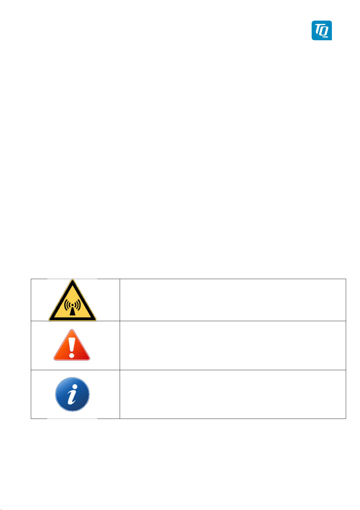
DANGER:
Advices whose non-observance can cause radiation damage to the
human body or ignition of combustible materials.
ATTENTION:
Advices whose non-observance can cause damage to the device or
other parts of the equipment or reduce the correct functionality of the
device.
INFORMATION:
Supplemental information for operating the device.
KTX2-F.A-MAN.0001.docx Page 9 of 74
© TQ-Systems GmbH. All information contained in this documents have to be treated strictly confidential. The transfer of presentations and know-how to third parties
requires the prior written consent of TQ-Systems GmbH.
Page 10

Abbr.
Meaning
Explanation
AA Aircraft
Assigned ICAO 24 bit address
AC Advisory Circular
ADC
Analog Digital
ADF
Automatic Direction
ADS
Automatic
ALT
Altitude
ABS
ATC
Air Traffic Control
ATCRBS
Air Traffic Control
A RF connector type.
Cyclical Redundancy
TQ Aviation KTX2-F.0100
EASA.AP445 MAN
1.5 Abbreviations
-B
Address
Information and guidance publication
Converter
Navigation equipment
Finder
Dependent
Surveillance
Broadcast
The transponder will respond to all interrogations and transmits
-B messages.
Radar Beacon
System
BAT Battery
BNC Bayonet Neill-
Concelman
CFR Code of Federal
Regulations
COMM Communication(s)
CRC
Check(s)
DME Distance Measuring
Equipment
EASA European Aviation
Safety Agency
ECR Engineering Change
Request
EEPROM Electrically Erasable
Programmable
Read-Only Memory
KTX2-F.A-MAN.0001.docx Page 10 of 74
© TQ-Systems GmbH. All information contained in this documents have to be treated strictly confidential. The transfer of presentations and know-how to third parties
requires the prior written consent of TQ-Systems GmbH.
Page 11

Abbr.
Meaning
Explanation
Administration
ABS
Aviation
TQ Aviation KTX2-F.0100
EASA.AP445 MAN
ENV Environment
ES Extended Squitter
ETSO European Technical
Standard Order
FAA Federal Aviation
FAX Facsimile
FCC Federal
Communications
Commission
FID Flight ID
Number of flight plan if assigned, else Registration number of
aircraft
FLY Flight The aircraft is in “Flight Mode”
FPGA Field-Programmable
Gate Array
GND Ground The transponder will respond to Mode S ground interrogations
from surface movement radar.
-B messages are transmitted (Surface messages).
GNSS Global Navigation
Satellite System
GPS Global Positioning
System
ICAO International Civil
Organization
IDT Identify
LSA Light Sport Aircraft
MAN Manual
MCU Microcontroller Unit
MIL Military
MTL Minimum Triggering
Level
KTX2-F.A-MAN.0001.docx Page 11 of 74
© TQ-Systems GmbH. All information contained in this documents have to be treated strictly confidential. The transfer of presentations and know-how to third parties
requires the prior written consent of TQ-Systems GmbH.
Page 12

Abbr.
Meaning
Explanation
Association
ABS
Aeronautics
Automotive
A RF connector type.
America
VFR
Visual Flight Rules
TQ Aviation KTX2-F.0100
EASA.AP445 MAN
NMEA National Marine
Electronics
ON Transponder Mode
“On”
RMC Recommended
Minimum Sentence
C
RSS Radio Standards
Specifications
(Canada)
RTCA Radio Technical
Commission for
SAE Society of
Engineers
The transponder will respond to all interrogations, but altitude
reporting is suppressed.
-B messages are transmitted.
NMEA sentence
SMA Sub-Miniature A
Connector
If activated on request by air traffic controller („Squawk Ident“) a
SPI
Special Position
Identification (ID)
SPI Pulse is transmitted for 18 seconds. This highlights the
respective traffic item on the radar screen of the air traffic
controller.
STBY Standby The transponder is on, but will not reply to any interrogations or
transmit any ADS-B out messages.
SUB Subminiature
SUPP Suppression
TNC Threaded Neill-
Concelman
TSO Technical Standard
Order[
USA United States of
KTX2-F.A-MAN.0001.docx Page 12 of 74
© TQ-Systems GmbH. All information contained in this documents have to be treated strictly confidential. The transfer of presentations and know-how to third parties
requires the prior written consent of TQ-Systems GmbH.
Page 13

Abbr.
Meaning
Explanation
VSWR
Voltage Standing
Augmentation
TQ Aviation KTX2-F.0100
EASA.AP445 MAN
Wave Ratio
WAAS Wide Area
System (GPS)
KTX2-F.A-MAN.0001.docx Page 13 of 74
© TQ-Systems GmbH. All information contained in this documents have to be treated strictly confidential. The transfer of presentations and know-how to third parties
requires the prior written consent of TQ-Systems GmbH.
Page 14
TQ Aviation KTX2-F.0100
EASA.AP445 MAN
1.6 Customer Support
In order to facilitate a rapid handling of returned shipments, please send your request to the
email address below. Additional information and FAX number can be found on the TQ
Avionics web portal:
https://www.tq-avionics.com/
Any suggestions for improvement
welcome. Contact: [email protected]
of our
manuals are
Information on software updates are available at TQ.
https://www.tq-avionics.com/
KTX2-F.A-MAN.0001.docx Page 14 of 74
© TQ-Systems GmbH. All information contained in this documents have to be treated strictly confidential. The transfer of presentations and know-how to third parties
requires the prior written consent of TQ-Systems GmbH.
Page 15

TQ Aviation KTX2-F.0100
EASA.AP445 MAN
1.7 Features
In order to operate the Mode-S transponder it is necessary to
request an ICAO 24-Bit Aircraft Address at the responsible
National Aviation Authorities. The received code must be
configured within the transponder (see chapter 3.4.2.1.2).
• Class 1 Level 2els Non-Diversity Mode-S-Transponder for ground based
interrogations at 1030 MHz and response at 1090 MHz
• Replies to Secondary Radar Interrogations
o Mode-A replies with a Squawk (one of 4096 possible Codes; e.g. flight plan
number, Squawk assigned by a Controller or the VFR Squawk).
o Mode C replies, including encoded Flight Level.
o Mode S replies, including Aircraft Address and Flight Level.
o IDENT capability for activating the “Special Position Identification“- Pulse
(SPI) for 18 seconds, which is requested by the Controller “Squawk Ident”
• ADS-B out:
o Airborne Position
o Identification and Category
o Airborne Velocity
o Operational Status
o Extended Squitter Aircraft Status
• Maximum flight level 30 000ft; maximum airspeed 250kt
• Display information contains Squawk code, mode of operation and pressure
altitude
•
Temperature compensated
high
precision
piezo-resistive pressure sensor
• RS-232 data port enabling connection with mutual suppression and On the Ground
(weight on wheels) inputs. In addition, an appropriate GNSS receiver for ADS-B
can be connected
• 8 storable entries for AA-/Aircraft-Code, FID
•
Ground-Switch support
KTX2-F.A-MAN.0001.docx Page 15 of 74
© TQ-Systems GmbH. All information contained in this documents have to be treated strictly confidential. The transfer of presentations and know-how to third parties
requires the prior written consent of TQ-Systems GmbH.
Page 16

TQ Aviation KTX2-F.0100
EASA.AP445 MAN
1.8 Safety-Conscious Utilization
For safe operation of the transponder the following notices have to be observed:
• The installation of the transponder into an aircraft should be carried out only by an authorized
installation company. The country regulations always have to be observed.
• Use the transponder only within the specified conditions, see chapter 7.
Power supply:
• Do not connect the transponder to AC sources.
• Make sure that the transponder is connected to the mandatory DC source, see chapter 7.
• Do not connect the transponder with reversed polarity to the DC source.
Circuit breaker:
• The transponder should be protected from the aircraft power supply by a dedicated 3 A circuit
breaker or fuse (slow-blow).
Excessive pulses on the DC bus of the aircraft may cause damage on electrical circuits of any installed
instrument.
Do not switch ON the transponder during engine start or shutdown.
1.9 Restriction for Use
The transponder is to be used only inside the declared limits.
KTX2-F.A-MAN.0001.docx Page 16 of 74
© TQ-Systems GmbH. All information contained in this documents have to be treated strictly confidential. The transfer of presentations and know-how to third parties
requires the prior written consent of TQ-Systems GmbH.
Page 17
TQ Aviation KTX2-F.0100
EASA.AP445 MAN
2. Operation
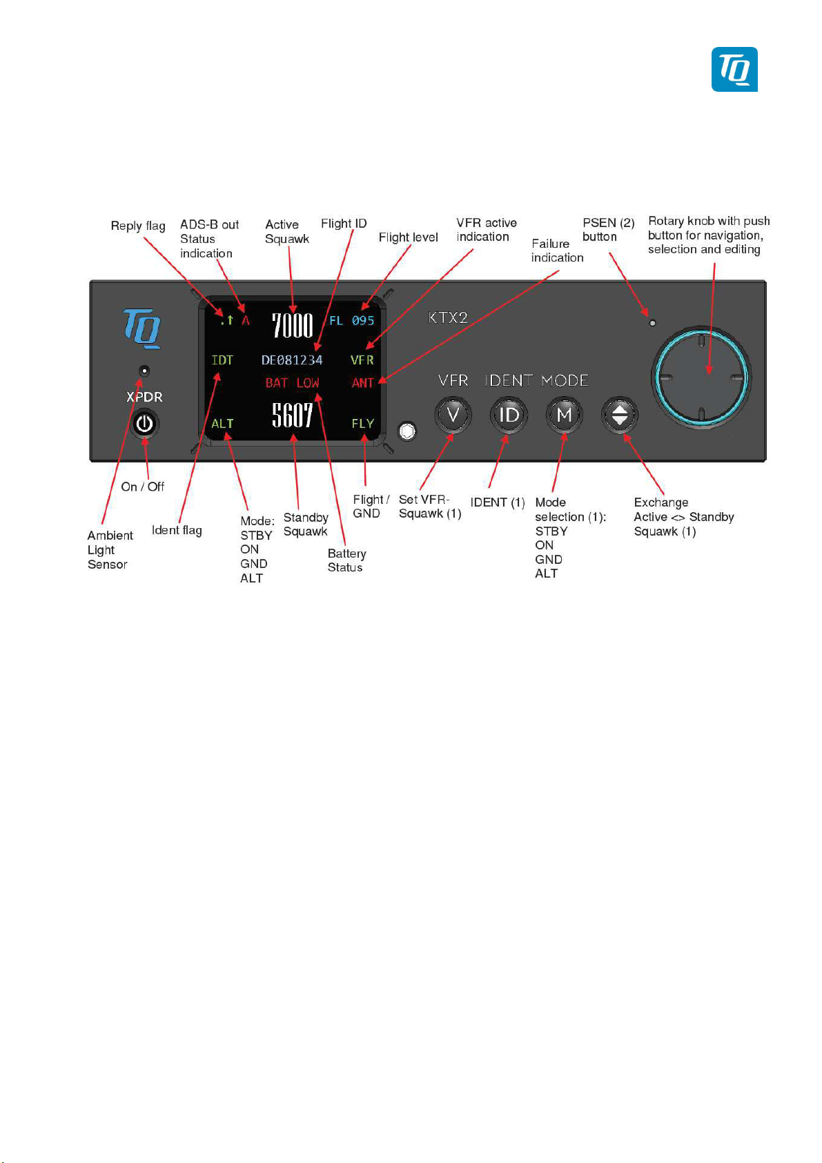
2.1 Controls and Display
Figure 1: Display Diagram
KTX2-F.A-MAN.0001.docx Page 17 of 74
© TQ-Systems GmbH. All information contained in this documents have to be treated strictly confidential. The transfer of presentations and know-how to third parties
requires the prior written consent of TQ-Systems GmbH.
Page 18
TQ Aviation KTX2-F.0100
EASA.AP445 MAN
2.1.1 Controls
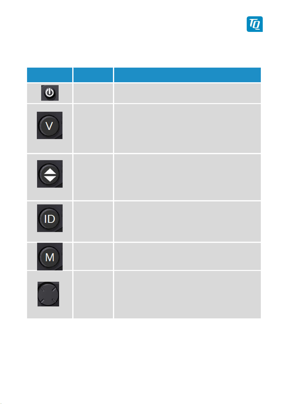
This chapter describes the use of the buttons and knobs during normal operation.
The usage while in setup mode is described in chapter 3.3.
Button Designation Function
ON/OFF
Press to switch the transponder on and off. This switch is
mechanically locked until it is pressed a second time
1. Activate/deactivate VFR Squawk
VFR
2. Pressing the button for more than 3 seconds will show the
Brightness menu (see 2.2.8.2)
1. Exchange of the active and standby-Squawk
CHANGE
2. Pressing the button for more than 3 seconds will show the
GNSS data menu (see 2.2.9)
1. „Squawk Ident“, a SPI Pulse is transmitted for 18 seconds
IDENT
(in normal mode).
2. Pressing the button for more than 3 seconds will show the
Flight-ID menu (see 2.2.8.1)
1. Select Transponder-Mode STBY, GND, ON or ALT.
MODE
2. Pressing the button for more than 3 seconds will toggle the
ADS-B mode (On/Off)
Rotary knob
1. Enter a new Squawk (see 2.2.2)
2. Enter values and select options in submenus (see 3.3)
3. Confirm Warnings and Notifications
Figure 2: Controls
KTX2-F.A-MAN.0001.docx Page 18 of 74
© TQ-Systems GmbH. All information contained in this documents have to be treated strictly confidential. The transfer of presentations and know-how to third parties
requires the prior written consent of TQ-Systems GmbH.
Page 19
changed with active Squawk
TQ Aviation KTX2-F.0100
EASA.AP445 MAN
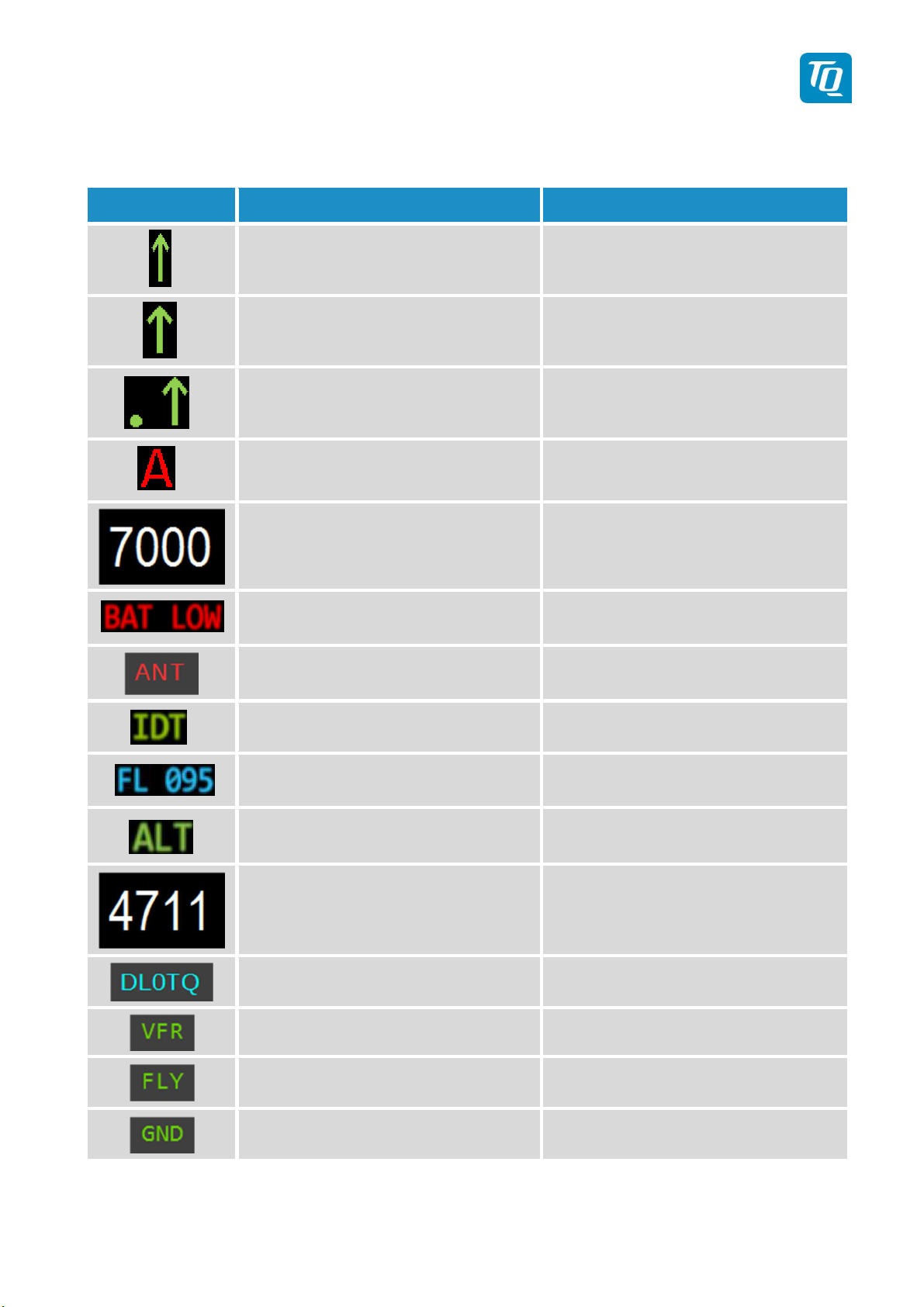
2.1.2 Display Indications
Indication Meaning Remark
Transponder is transmitting
Mode-A/C Replies on
Interrogations
Transponder is transmitting
Mode-S Replies on
Interrogations
Transponder is locked by a
ground station and will be
directly addressed
Appears per reply and persists for
some time
Appears per reply and persists for
some time
Appears at every addressed reply and
persists for some time
ADS-B out Status Status of ADS-B transmission
Active Squawk Is shown at upper position
Battery power too low Appears above Standby-Squawk
Failure indication See 4
Figure 3: Indicators
IDENT- Marking is transmitted
ID („Squawk Ident“) has been pressed
– active for 18s
Current Flight Level Flight Level (in 100ft steps)
Mode display
(STBY, ON, GND, ALT)
see chapter. 2.1.6 TransponderModes
Is shown at lower position.
Standby-Squawk
Can be ex
by pressing the UP/DOWN (“Change”)
button
Flight ID
Only shown if a Flight ID is configured
with a valid Aircraft Address
VFR indication Shown while VFR squawk is used
Transponder is in airborne mode
Transponder is in ground mode
Only shown if Ground Switch support
is configured.
Only shown if Ground Switch support
is configured.
KTX2-F.A-MAN.0001.docx Page 19 of 74
© TQ-Systems GmbH. All information contained in this documents have to be treated strictly confidential. The transfer of presentations and know-how to third parties
requires the prior written consent of TQ-Systems GmbH.
Page 20
TQ Aviation KTX2-F.0100
EASA.AP445 MAN
2.2
Normal Operation
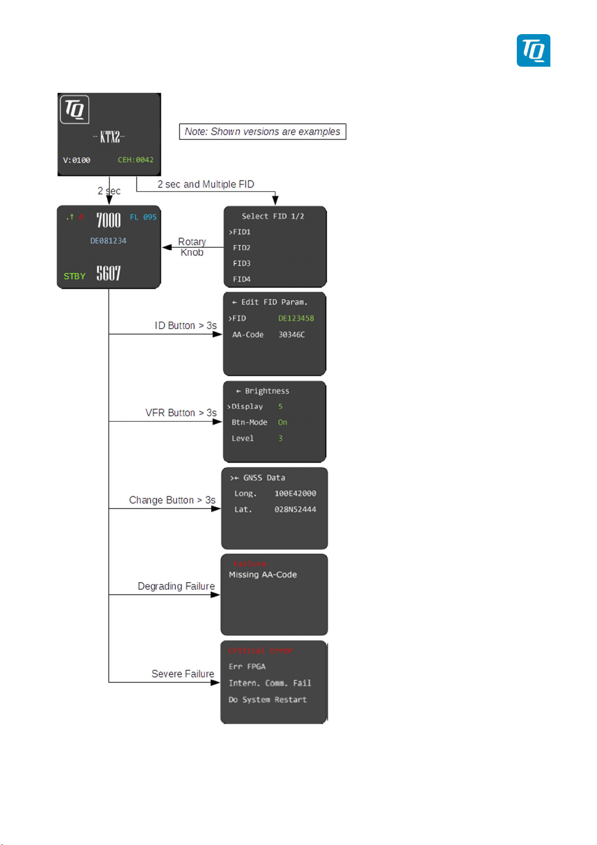
Menu Structure
Figure 4: Operational menu structure
KTX2-F.A-MAN.0001.docx Page 20 of 74
© TQ-Systems GmbH. All information contained in this documents have to be treated strictly confidential. The transfer of presentations and know-how to third parties
requires the prior written consent of TQ-Systems GmbH.
Page 21
TQ Aviation KTX2-F.0100
EASA.AP445 MAN
2.2.1 ON/OFF Switching
To switch on the transponder press the ON/OFF button once. The button will be locked in its “ON”
position. Press the button again to switch it off.
The initial display is shown shortly after the transponder is switched on (see figure below).
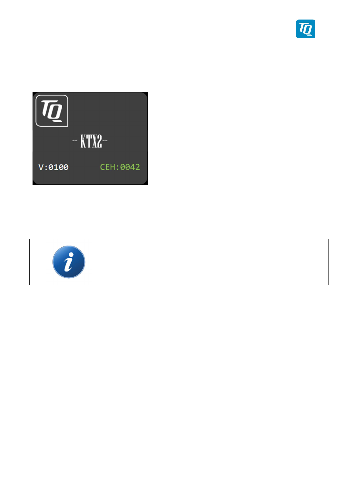
Figure 5: Initial Display
The initial display shows the current software and FPGA version.
After approx. two (2) seconds the transponder switches either to its normal operation display or a
selection menu is shown if multiple Flight IDs are configured.
If a failure is detected during start-up a fault notification is displayed. In
that case see chapter 4 for details.
2.2.1.1 Multiple Flight ID selection
If multiple Flight IDs are configured a selection menu is displayed.
2.2.1.2 Normal operation
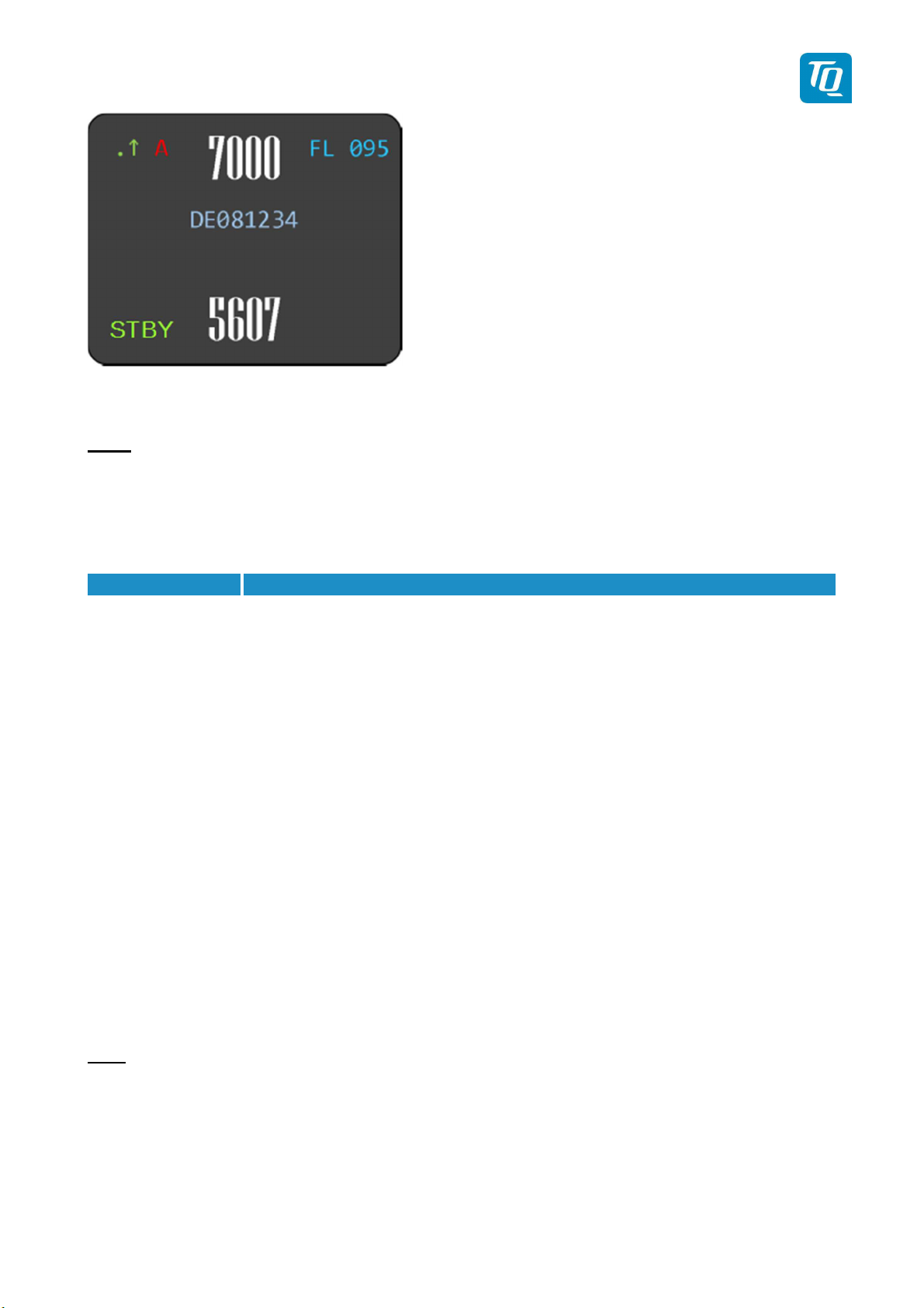
The normal operation always starts in standby mode. The normal operation display is shown as follows:
KTX2-F.A-MAN.0001.docx Page 21 of 74
© TQ-Systems GmbH. All information contained in this documents have to be treated strictly confidential. The transfer of presentations and know-how to third parties
requires the prior written consent of TQ-Systems GmbH.
Page 22
Mode
Explanation
ADS
ADS
ADS
ALT
ADS
TQ Aviation KTX2-F.0100
EASA.AP445 MAN
Figure 6: Normal Operation
Note:
The Flight ID is not displayed if no valid Flight ID is configured.
2.2.2 Transponder-
Modes
The currently active mode is displayed at the lower left corner of the display.
STBY Transponder is switched on but
does not
respond to any interrogation.
-B out is disabled.
GND Transponder responds to Mode-S interrogations.
-B out is enabled (Surface Squitter).
ON Transponder responds to all interrogations, but altitude is not transmitted.
-B out is enabled.
Transponder responds to all interrogations.
-B out is enabled.
Table 1: Transponder Modes
During the flight the Mode “ALT” should always be set, unless the ATC gives other instructions.
While rolling on the ground the transponder should be set to “GND”.
If the installation includes a weight on wheels switch and it is correctly configured then the mode is
changed automatically.
To change the mode press the “MODE” button until the desired mode is displayed.
The “MODE” button is also used to enable or disable the ADS-B out function. Press the “MODE” button
for at least 3 seconds until the ADS-B indication changes (see 2.2.7).
Note:
The ADS-B out function is enabled by default if a GNSS device is configured (see 3.4.2.1.3.4).
KTX2-F.A-MAN.0001.docx Page 22 of 74
© TQ-Systems GmbH. All information contained in this documents have to be treated strictly confidential. The transfer of presentations and know-how to third parties
requires the prior written consent of TQ-Systems GmbH.
Page 23
TQ Aviation KTX2-F.0100
EASA.AP445 MAN
2.2.3 Squawk Code Change
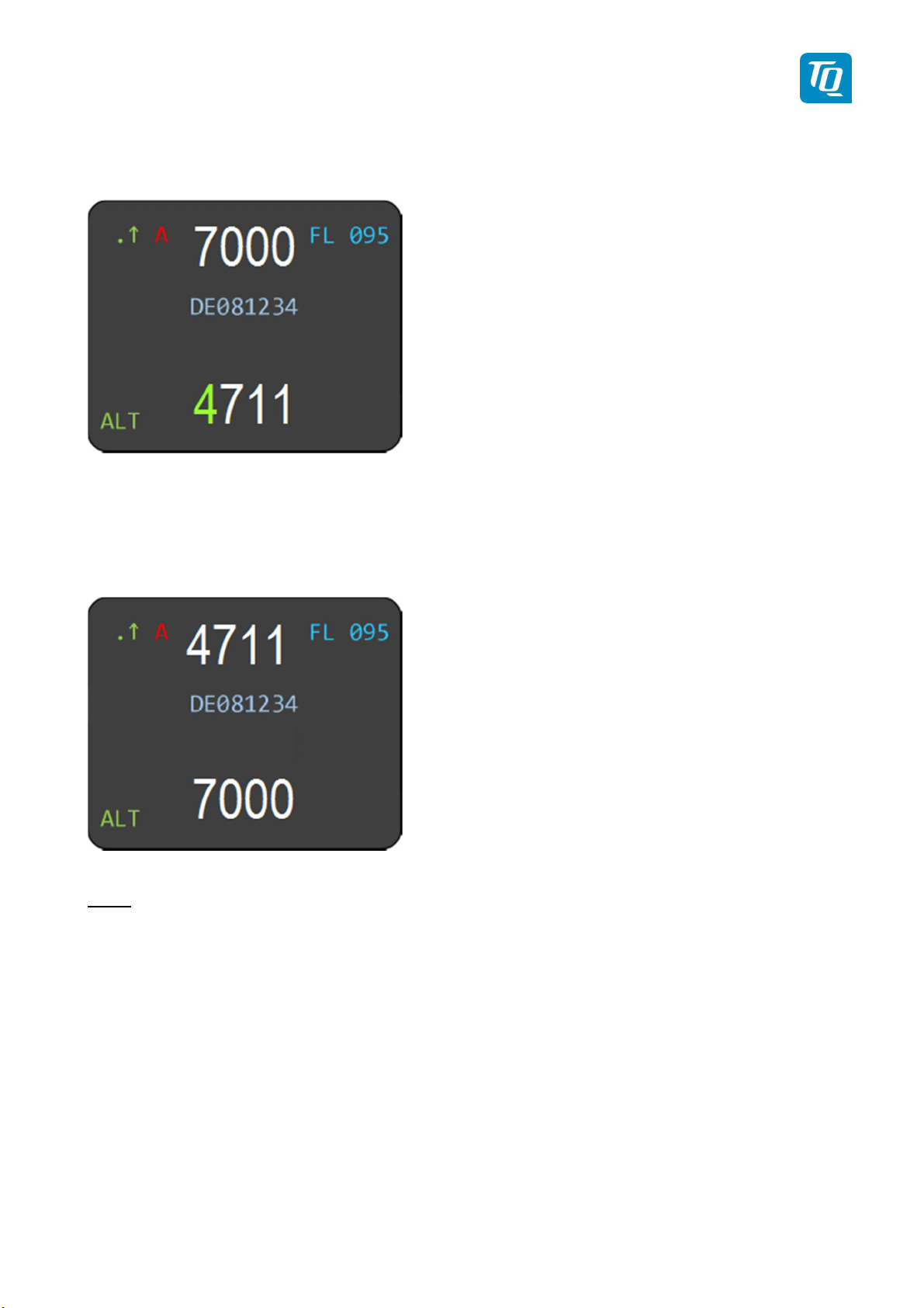
To change the squawk code perform the following procedure:
1. Press the rotary knob. The first digit of the standby squawk turns green.
2. Turn the rotary knob to change the value.
3. Press the rotary knob again to save the selected digit. The next digit turns green.
4. Repeat steps 2 and 3 until all four (4) digits are set to desired squawk code.
5. Press the “Change” button. The standby squawk code is exchanged with the currently active
squawk code.
Note:
The top line shows always the active squawk.
KTX2-F.A-MAN.0001.docx Page 23 of 74
© TQ-Systems GmbH. All information contained in this documents have to be treated strictly confidential. The transfer of presentations and know-how to third parties
requires the prior written consent of TQ-Systems GmbH.
Page 24
TQ Aviation KTX2-F.0100
EASA.AP445 MAN
2.2.4
VFR –
Squawk
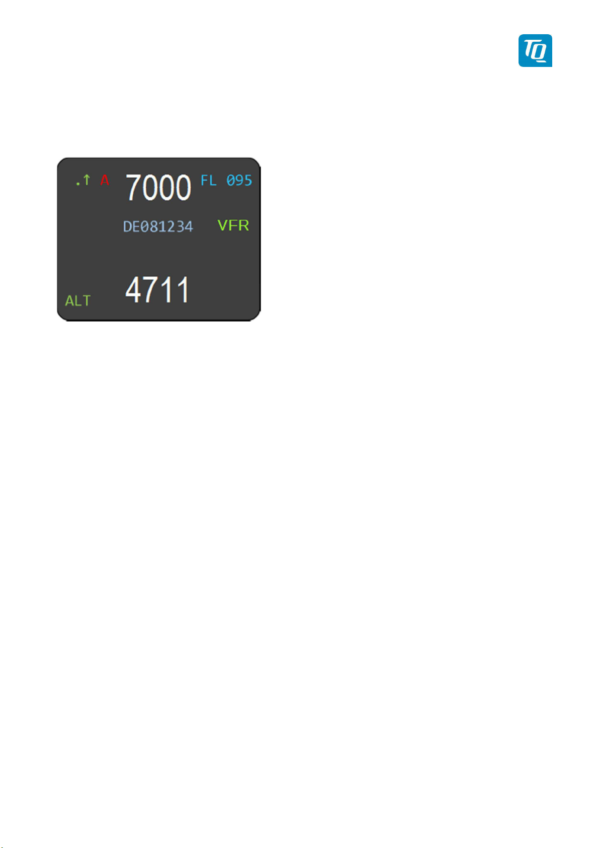
To set the active squawk to a predefined code press the “VFR” button. The VFR-squawk code is now
shown as active squawk. “VFR” is indicated on the right hand side of the display and the former active
squawk becomes the standby squawk.
Figure 7: VFR-Squawk
Press the “VFR” button again to restore the previous squawk code as active squawk. The “VFR”
indication disappears.
The factory setting of the VFR-Squawk code is 7000. The VFR-squawk code can be configured in
accordance with local requirements using the setup mode (see 3.4.3).
KTX2-F.A-MAN.0001.docx Page 24 of 74
© TQ-Systems GmbH. All information contained in this documents have to be treated strictly confidential. The transfer of presentations and know-how to third parties
requires the prior written consent of TQ-Systems GmbH.
Page 25
TQ Aviation KTX2-F.0100
EASA.AP445 MAN
2.2.5
Squawk
Ident (ID, SPI)
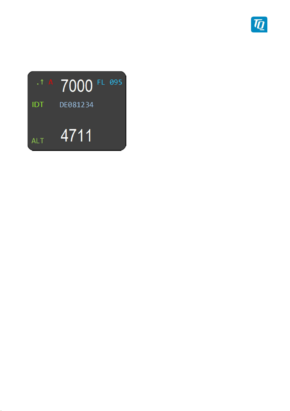
Press the “IDENT” button if the ATC requests you to send “Ident” or “Squawk Ident”.
For 18 seconds the Ident Pulse is activated in the transponder replies. This is indicated by “IDT” on the
left hand side of the display.
Figure 8: Squawk Ident
2.2.6
Airborne
/Ground Indication
If the aircraft is equipped with a “weight on wheels” switch or has an automatic air/ground system the
transponder can be configured to use it for Airborne/Ground mode switching (see 3.4.2.1.3.2).
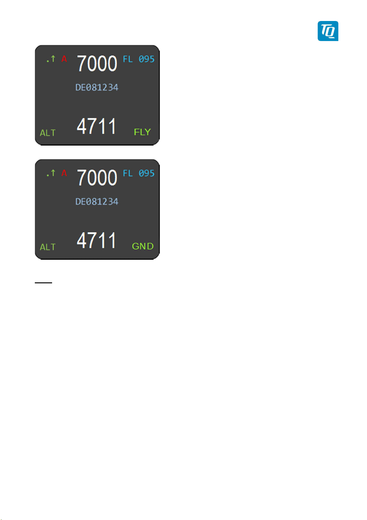
Depending on the status either “FLY” (Flight) or “GND” (Ground) is shown on the display in the lower
right corner.
KTX2-F.A-MAN.0001.docx Page 25 of 74
© TQ-Systems GmbH. All information contained in this documents have to be treated strictly confidential. The transfer of presentations and know-how to third parties
requires the prior written consent of TQ-Systems GmbH.
Page 26
TQ Aviation KTX2-F.0100
EASA.AP445 MAN
Figure 9: Airborne/Ground Indication "FLY"
Figure 10: Airborne/Ground Indication "GND"
Note:
If this function is not activated, no indications are displayed and the mode must be manually
selected (see 2.2.2).
KTX2-F.A-MAN.0001.docx Page 26 of 74
© TQ-Systems GmbH. All information contained in this documents have to be treated strictly confidential. The transfer of presentations and know-how to third parties
requires the prior written consent of TQ-Systems GmbH.
Page 27
B out function is active and transmitting
B out function is active and transmitting
type ZERO position messages or no position
TQ Aviation KTX2-F.0100
EASA.AP445 MAN
2.2.7 ADS-B Status Indication
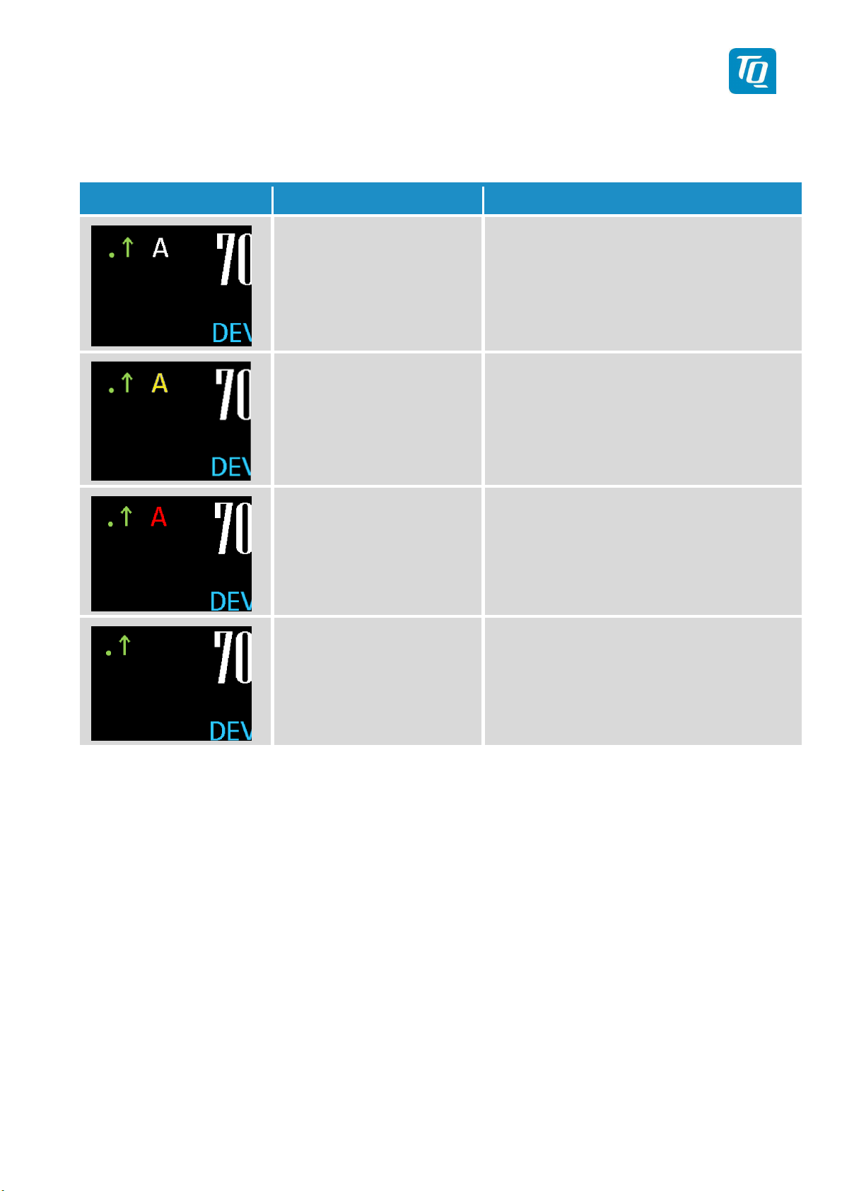
The current operational status of the ADS-B is shown on the display as follows:
Indication Function Description
ADS-B enabled.
Letter “A” appears in white
color.
ADS-B enabled.
Letter “A” appears in yellow
color.
ADS-B enabled.
Letter “A” appears in red
color.
ADS-B disabled.
No letter “A” displayed.
ADSmessages.
ADS-B out function is active but not
transmitting messages.
ADS-
messages due to missing position data
(longitude, altitude, latitude).
No ADS-B data is transmitted.
Figure 11: ADS-B Indication
Note: Above images show the upper left section of the display only.
KTX2-F.A-MAN.0001.docx Page 27 of 74
© TQ-Systems GmbH. All information contained in this documents have to be treated strictly confidential. The transfer of presentations and know-how to third parties
requires the prior written consent of TQ-Systems GmbH.
Page 28
TQ Aviation KTX2-F.0100
EASA.AP445 MAN
2.2.8
Adjustable
parameters in normal operation mode
Some parameters can be changed while in normal operation mode. The changes are effective
immediately after confirmation, but will remain only until the transponder is powered off.
Note:
To make changes permanently the parameters have to be changed in setup mode (see 3).
2.2.8.1 Flight ID
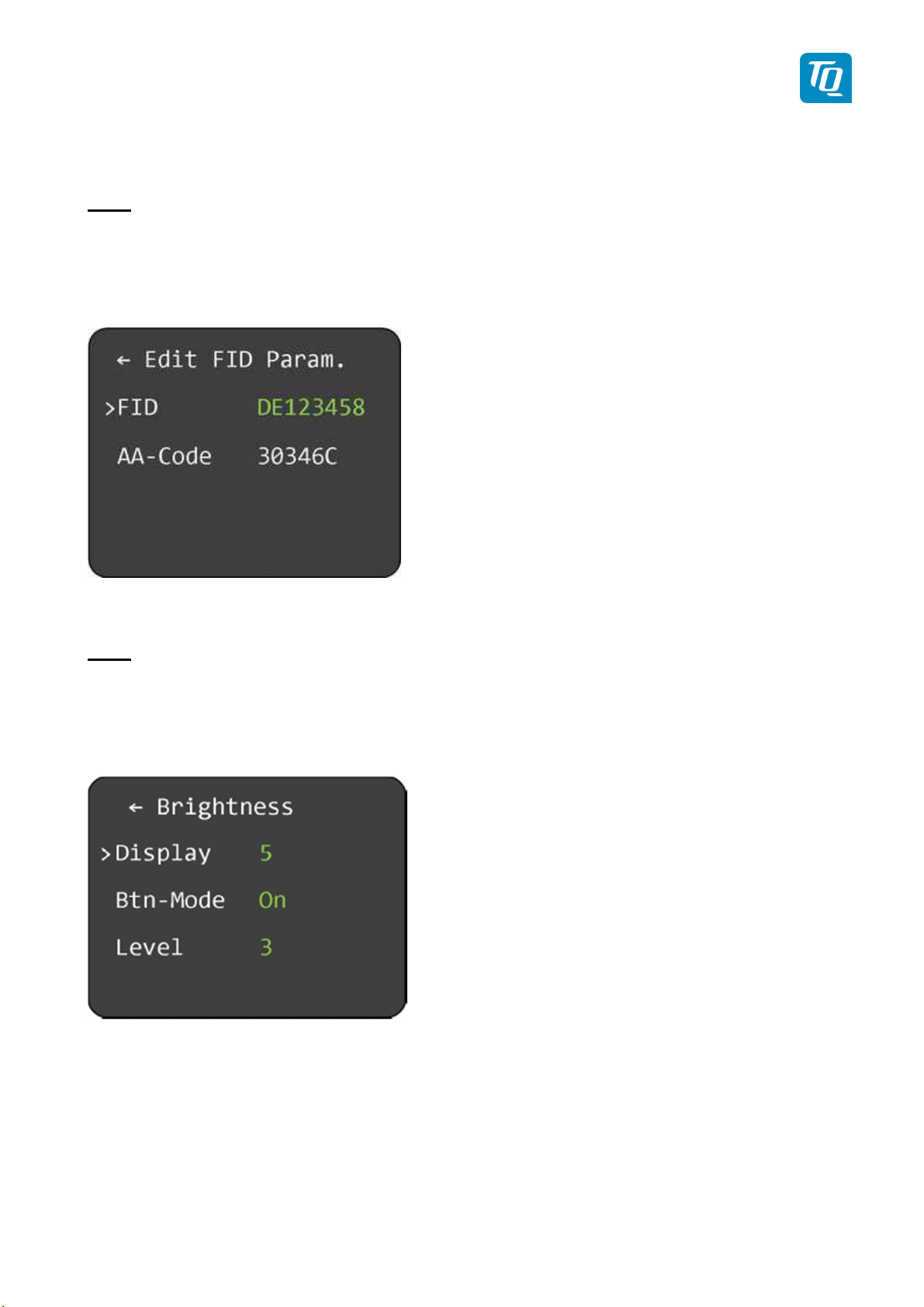
To modify the Flight ID press the ID button for at least 3 seconds.
Figure 12: Change Flight ID
The Flight ID can be adjusted in the same way as described in chapter 3.4.2.1.
Note:
The AA-Code is shown for information only and cannot be changed.
2.2.8.2 Brightness
To modify the display brightness and the button illumination press the VFR button for at least 3 seconds.
Figure 13: Change Brightness
To change the display brightness select “Display” and press the rotary knob.
Turn the rotary knob to change the value for brightness between 1 (lowest) to 5 (highest). Press the
rotary knob to save the new value.
KTX2-F.A-MAN.0001.docx Page 28 of 74
© TQ-Systems GmbH. All information contained in this documents have to be treated strictly confidential. The transfer of presentations and know-how to third parties
requires the prior written consent of TQ-Systems GmbH.
Page 29

TQ Aviation KTX2-F.0100
EASA.AP445 MAN
2.2.8.3 Button Config
To change the button illumination select “Btn-Mode” and press the rotary knob.
The button illumination has three (3) modes: Off, On and Auto.
Turning the rotary knob will change the mode. Press the rotary knob again to confirm the mode.
Depending on the selected mode further parameters can be configured.
2.2.8.3.1 Button Illumination Mode “Off”
If this mode is selected the button illumination is switched off. No further parameters can be configured.
2.2.8.3.2 Button Illumination Mode “On”
If this mode is selected the button illumination is switched on.
To change the illumination level select “Level” and press the rotary knob. Turn the rotary knob to change
the value between 1 (dark) to 5 (bright). Press the rotary knob to save the new value.
2.2.8.3.3 Button Illumination Mode “Auto”
If this mode is selected the button illumination is switched between a day and night setting depending on
the ambient light sensor. No further parameters can be configured.
The settings can only be configured in setup mode, see chapter 3.4.1.
KTX2-F.A-MAN.0001.docx Page 29 of 74
© TQ-Systems GmbH. All information contained in this documents have to be treated strictly confidential. The transfer of presentations and know-how to third parties
requires the prior written consent of TQ-Systems GmbH.
Page 30
TQ Aviation KTX2-F.0100
EASA.AP445 MAN
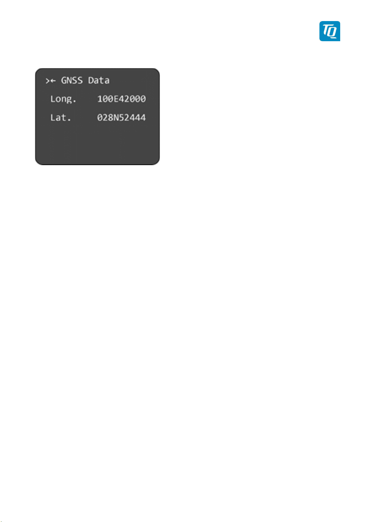
2.2.9 GNSS Data
Press the “Change” button for at least 3 seconds to display the actual GNSS position data.
Figure 14: GNSS Data Display
Press the rotary knob to return to the normal operation display.
KTX2-F.A-MAN.0001.docx Page 30 of 74
© TQ-Systems GmbH. All information contained in this documents have to be treated strictly confidential. The transfer of presentations and know-how to third parties
requires the prior written consent of TQ-Systems GmbH.
Page 31
Sensor
TQ Aviation KTX2-F.0100
EASA.AP445 MAN
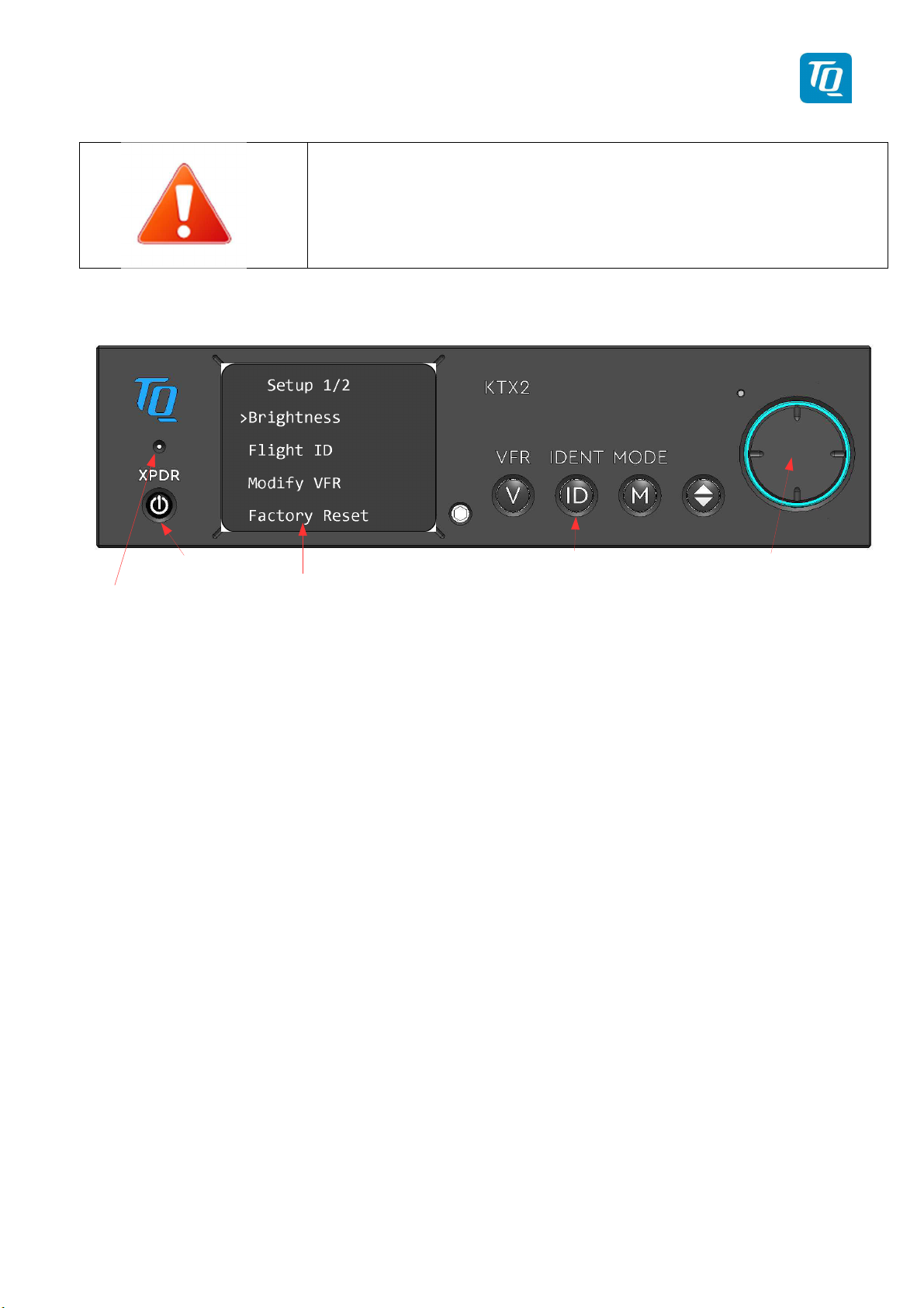
3. Setup Mode
Do not use Setup Mode in flight.
Check with your avionics installer before
changing the configuration.
3.1
Controls
Ambient
Ambient
Light
Light
Sensor
Figure 15: Button functions in Setup Mode
and Display
On / Off
Setup Display
Enter Setup Mode
Cancel
Discard
Rotary knob with push
button for navigation,
selection and editing
KTX2-F.A-MAN.0001.docx Page 31 of 74
© TQ-Systems GmbH. All information contained in this documents have to be treated strictly confidential. The transfer of presentations and know-how to third parties
requires the prior written consent of TQ-Systems GmbH.
Page 32
TQ Aviation KTX2-F.0100
EASA.AP445 MAN
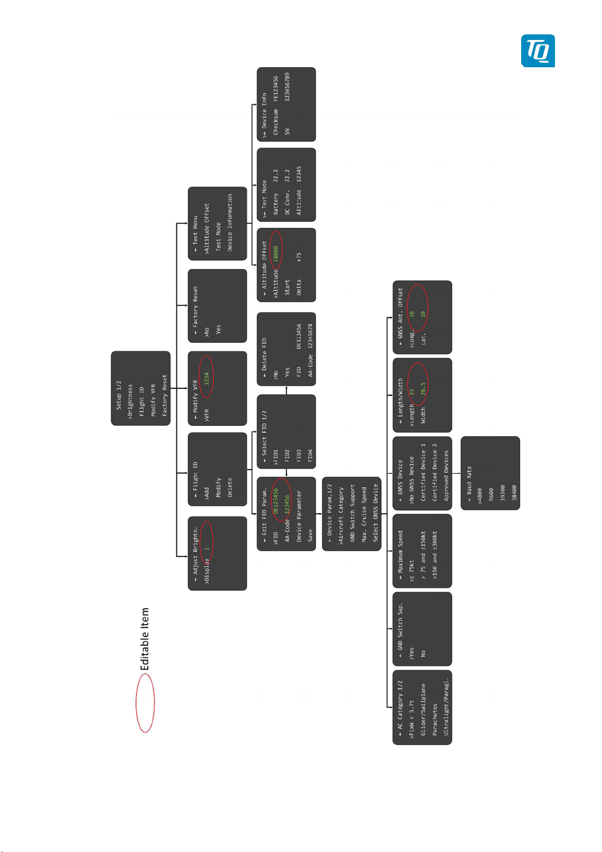
Figure 16: Setup mode menu structure
KTX2-F.A-MAN.0001.docx Page 32 of 74
© TQ-Systems GmbH. All information contained in this documents have to be treated strictly confidential. The transfer of presentations and know-how to third parties
requires the prior written consent of TQ-Systems GmbH.
Page 33
TQ Aviation KTX2-F.0100
EASA.AP445 MAN
3.2 Entering Set Up
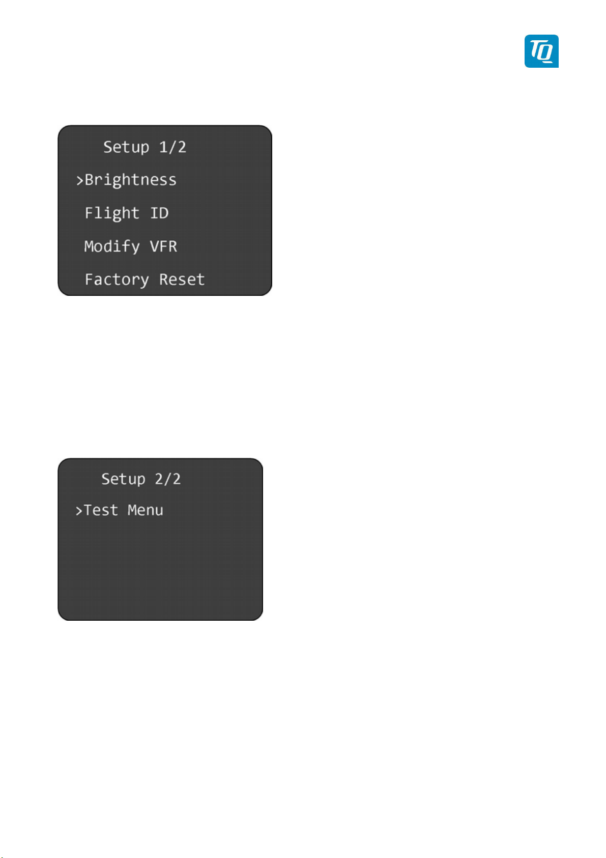
To enter the setup mode, press the “IDENT” button while switching on the transponder and the setup
menu appears as shown below.
Figure 17: Setup Menu 1
3.3 Controls
3.3.1 Selection
Turning the rotary knob moves to the desired menu item.
Press the rotary knob to select the desired parameter for configuration or to enter a submenu.
If a menu consists of several pages, e.g. the setup menu, the next page can be accessed by turning the
rotary knob clockwise until the next page is shown. To go back turn the rotary knob counterclockwise
until the previous page is displayed.
Figure 18: Setup Menu 2
3.3.2 Return to parent menu
Any menu showing an arrow left of the headline can be left by selecting the headline and pressing the
rotary knob. The previous menu will be displayed.
3.3.3 Cancel/Discard
The “IDENT” button can be used for cancelling, discarding or returning.
KTX2-F.A-MAN.0001.docx Page 33 of 74
© TQ-Systems GmbH. All information contained in this documents have to be treated strictly confidential. The transfer of presentations and know-how to third parties
requires the prior written consent of TQ-Systems GmbH.
Page 34
TQ Aviation KTX2-F.0100
EASA.AP445 MAN
While editing pressing the “IDENT” button briefly will cancel the current editing. The previous
configuration value is restored.
While in a submenu pressing the “IDENT” button briefly will return to the previous menu.
Pressing the “IDENT” button for at least 3 seconds will discard any unsaved changes and return to the
main setup menu.
3.4 Setup Menus
3.4.1 Brightness
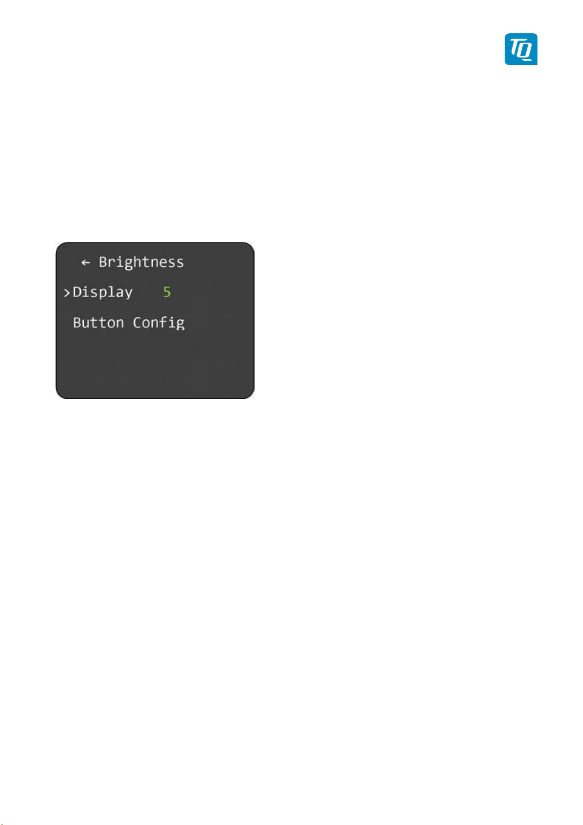
To change the display brightness select “Display” and press the rotary knob.
Turn the rotary knob to change the value for brightness between 1 (lowest) to 5 (highest). Press the
rotary knob to save the new value.
Figure 19: Setup Brightness Menu
3.4.1.1 Button Config
To change the button illumination select “Button Config” and press the rotary knob. A menu for
configuring the button illumination and its modes is displayed.
The button illumination has three (3) modes: Off, On and Auto.
To change the mode select “Mode” and press the rotary knob. Turning the rotary knob will change the
mode. Press the rotary knob again to confirm the mode.
Depending on the selected mode several parameters can be configured.
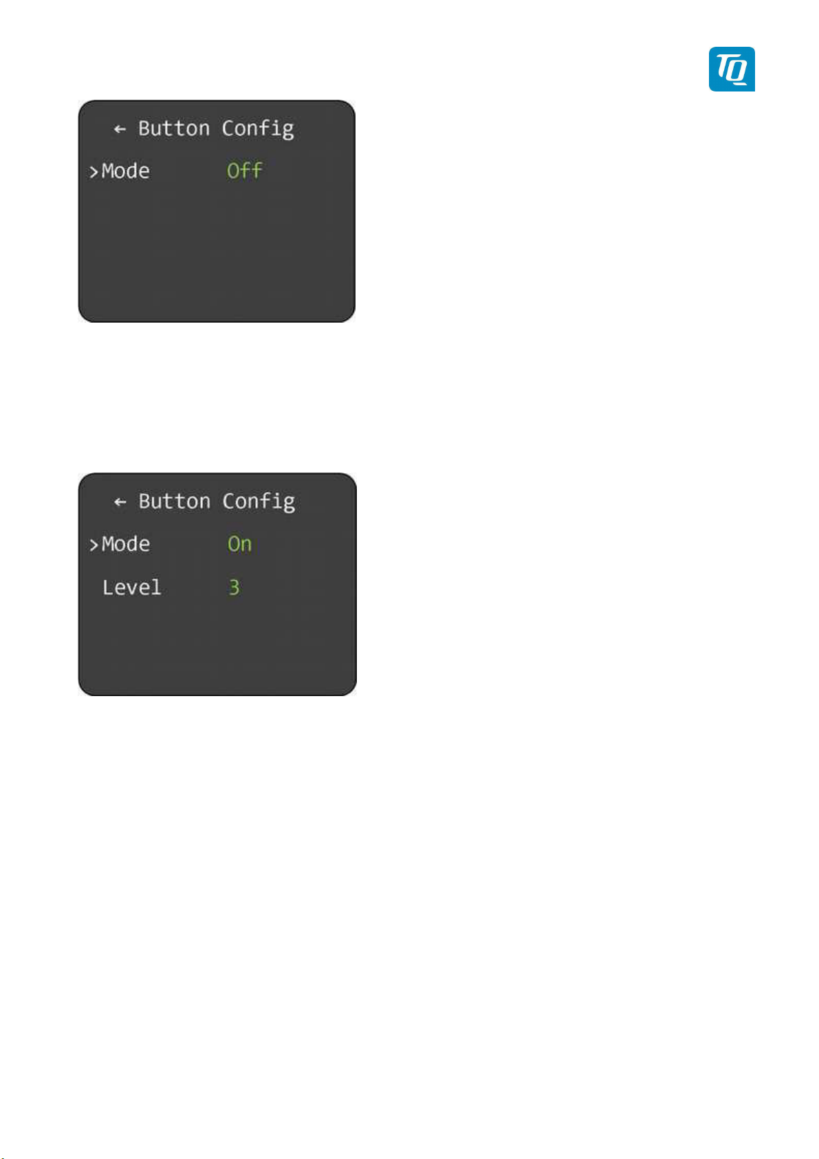
3.4.1.1.1 Button Illumination Mode “Off”
If this mode is selected the button illumination is switched off. No further parameters can be configured.
KTX2-F.A-MAN.0001.docx Page 34 of 74
© TQ-Systems GmbH. All information contained in this documents have to be treated strictly confidential. The transfer of presentations and know-how to third parties
requires the prior written consent of TQ-Systems GmbH.
Page 35
TQ Aviation KTX2-F.0100
EASA.AP445 MAN
Figure 20: Button Illumination Mode "Off"
3.4.1.1.2 Button Illumination Mode “On”
If this mode is selected the button illumination is switched on.
To change the illumination level select “Level” and press the rotary knob. Turn the rotary knob to change
the value between 1 (dark) to 5 (bright). Press the rotary knob to save the new value.
Figure 21: Button Illumination Mode "On"
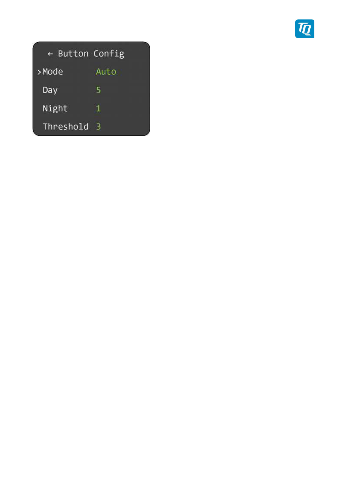
3.4.1.1.3 Button Illumination Mode “Auto”
If this mode is selected the button illumination is switched between a day and night setting depending on
the ambient light sensor.
To change the illumination level for day or night select appropriate menu item (“Day”, “Night”) and press
the rotary knob. Turn the rotary knob to change the value between 0 (off) to 5 (bright). Press the rotary
knob to save the new value.
To change the threshold level for the day/night switching select “Threshold” and press the rotary knob.
Turn the rotary knob to change the value between 1 (high light sensitivity) to 5 (low light sensitivity).
Press the rotary knob to save the new value.
KTX2-F.A-MAN.0001.docx Page 35 of 74
© TQ-Systems GmbH. All information contained in this documents have to be treated strictly confidential. The transfer of presentations and know-how to third parties
requires the prior written consent of TQ-Systems GmbH.
Page 36
TQ Aviation KTX2-F.0100
EASA.AP445 MAN
Figure 22: Button Illumination Mode "Auto"
KTX2-F.A-MAN.0001.docx Page 36 of 74
© TQ-Systems GmbH. All information contained in this documents have to be treated strictly confidential. The transfer of presentations and know-how to third parties
requires the prior written consent of TQ-Systems GmbH.
Page 37
TQ Aviation KTX2-F.0100
EASA.AP445 MAN
3.4.2 Flight-Identifier (Flight ID)
The transponder can store up to eight flight IDs for multiple aircraft configurations (e.g. in a portable
station as used in hot-air/gas filled balloons).
For multiple flight IDs, an appropriate Aircraft Address must be assigned to each of the flight IDs.
See 3.4.2.4 for details.
Note:
ICAO regulations require Mode-S data to contain a valid flight identification (FID), to ensure automatic
exchange of flight plan and radar data. Commercial flights usually have their own FIDs. General aviation
FIDs should be the registration letters or numbers of the aircraft. The FID must not be confused with the
24-bit Aircraft Address. The FID is left aligned and shown in green characters. The FID may not contain
any blanks.
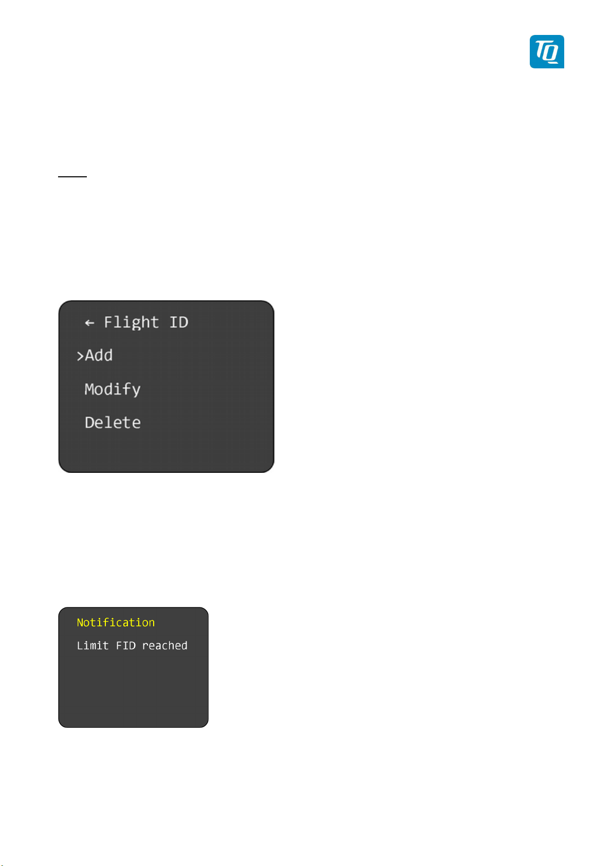
To configure a Flight ID configuration select “Flight ID” and press the rotary knob. A menu for adding,
modifying and deleting a Flight ID configuration is displayed.
Figure 23: Flight ID configuration
Select “Add” to add a Flight ID, “Modify” to modify a Flight ID or “Delete” to delete a Flight ID and press
the rotary knob.
3.4.2.1 Add/Edit Flight ID
To add a Flight ID select “Add” and press the rotary knob.
If all eight possible IDs are already configured the following notification is displayed.
Figure 24: FID Limitation Notification
If this message appears you can either modify an existing entry (see 3.4.2.2) or delete an existing entry
(see 3.4.2.3) and add a new one as shown below.
KTX2-F.A-MAN.0001.docx Page 37 of 74
© TQ-Systems GmbH. All information contained in this documents have to be treated strictly confidential. The transfer of presentations and know-how to third parties
requires the prior written consent of TQ-Systems GmbH.
Page 38
TQ Aviation KTX2-F.0100
EASA.AP445 MAN
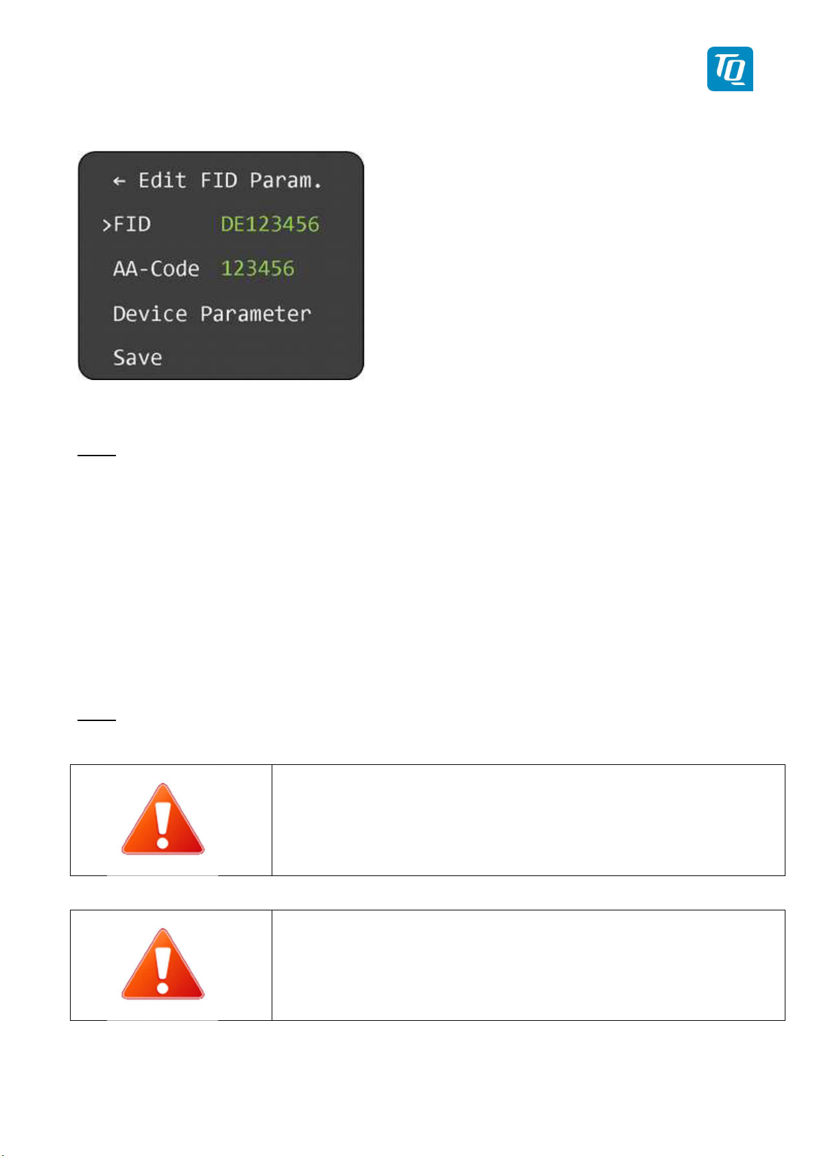
If a new Flight ID can be added a submenu “Edit FID Param.” is displayed.
Figure 25: Flight ID Edit Menu
Note:
All configuration settings of a new Flight ID are set to their default values.
3.4.2.1.1 Flight ID Value
To configure the Flight ID perform the following procedure:
1. Select “FID” and press the rotary knob to start editing a Flight ID. The first character turns yellow.
2. Turn the rotary knob to change the value.
3. Press the rotary knob again to save the selected character. The next character turns yellow.
4. Repeat steps 2 and 3 until all characters (max. 8) are set to desired value.
5. Saving the 8
th
character will end the editing. If the Flight ID contains less than 8 characters then
enter a space as last character to end the editing.
Note:
After editing the changed value is not saved automatically! You have to select “Save” once all data have
been configured (see 3.4.2.1.4).
Enter the FID left-aligned, without any blanks or dashes
(!), e.g. DENWS for the marking D-ENWS.
A missing FID disables mode-S operation and A/Cmode only will be engaged.
See chapter “4 Self-Test, Errors and Warnings”
KTX2-F.A-MAN.0001.docx Page 38 of 74
© TQ-Systems GmbH. All information contained in this documents have to be treated strictly confidential. The transfer of presentations and know-how to third parties
requires the prior written consent of TQ-Systems GmbH.
Page 39
TQ Aviation KTX2-F.0100
EASA.AP445 MAN
3.4.2.1.2 Aircraft Address (AA) Value
To configure the Aircraft Address (AA) perform the following procedure:
1. Select “AA” and press the rotary knob to start editing the AA. The first digit turns yellow.
2. Turn the rotary knob to change the value.
3. Press the rotary knob again to save the selected digit. The next character turns yellow.
4. Repeat steps 2 and 3 until all digits are set to desired value.
Note:
After editing the changed value is not saved automatically! You have to select “Save” once all data have
been configured (see 3.4.2.1.4).
Note:
Before you can enter the Aircraft Address, the Flight ID needs to be defined.
Note:
All values except “000000” and “FFFFFFF” are valid. The transponder accepts all values but if an invalid
value is used as Aircraft Address the transponder will show a failure and the transponder switches to
AC-only mode.
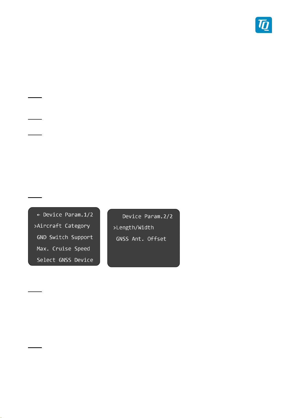
3.4.2.1.3 Device Parameter
To configure the parameters associated to a Flight ID select “Device Parameter" and press the rotary
knob. A submenu “Device Param.” is displayed.
Note:
The submenu “Device Parameter” consists of two (2) pages.
Figure 26: Device Parameter Configuration Menu
Note:
After changing any parameter the new value is not saved automatically! You have to select “Save” once
all data have been configured (see 3.4.2.1.4).
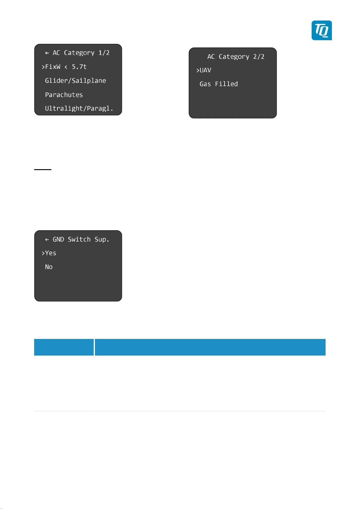
3.4.2.1.3.1 Aircraft Category
To configure the aircraft category select “Aircraft Category" and press the rotary knob. A submenu “AC
Category” is displayed.
Note:
The submenu “Device Parameter” consists of two (2) pages.
KTX2-F.A-MAN.0001.docx Page 39 of 74
© TQ-Systems GmbH. All information contained in this documents have to be treated strictly confidential. The transfer of presentations and know-how to third parties
requires the prior written consent of TQ-Systems GmbH.
Page 40
GND Switch
Explanation
TQ Aviation KTX2-F.0100
EASA.AP445 MAN
Figure 27: Aircraft Category Selection Menu
Turn the rotary switch to select the desired aircraft category and press the rotary knob to confirm.
Note:
The transponder is not yet certified for A/C FixW>5.7t, speed >250kts and helicopters (RotorCr).
Therefore, these items are not yet selectable.
3.4.2.1.3.2 Ground Switch
To activate or deactivate the Airborne/Ground switch function select “GND Switch Support” and press
the rotary knob. A submenu “GND Switch Sup.” is displayed.
Figure 28: Ground Switch Setup Menu
Turn the rotary knob to select Yes or No and press the rotary know to confirm.
Support
Yes The Airborne/Ground switch function is enabled. The transponder switches
the Airborne/Ground mode automatically depending on the status of the
Ground Switch input (see 5.1.3).
No The Airborne/Ground switch function is disabled. Airborne/Ground mode has
Table 2: GND Switch Support
3.4.2.1.3.3 Speed Category
To configure the maximum speed category select “Max. Cruise Speed" and press the rotary knob. A
submenu “Maximum Speed” is displayed.
KTX2-F.A-MAN.0001.docx Page 40 of 74
© TQ-Systems GmbH. All information contained in this documents have to be treated strictly confidential. The transfer of presentations and know-how to third parties
requires the prior written consent of TQ-Systems GmbH.
to be switched manually using the mode button (see 2.2.2).
Page 41

TQ Aviation KTX2-F.0100
EASA.AP445 MAN
Figure 29: Maximum Speed Category Selection Menu
Turn the rotary switch to select the desired speed category and press the rotary knob to confirm.
KTX2-F.A-MAN.0001.docx Page 41 of 74
© TQ-Systems GmbH. All information contained in this documents have to be treated strictly confidential. The transfer of presentations and know-how to third parties
requires the prior written consent of TQ-Systems GmbH.
Page 42
Certified
GNSS Unit
Remarks
Approved GNSS Unit
Remarks
TQ Aviation KTX2-F.0100
EASA.AP445 MAN
3.4.2.1.3.4 Select GNSS Device
If the ADS-B function is used, an appropriate WAAS GNSS source needs to be connected (see 5.1.5).
This transponder is certified to TSO-C166b and meets the requirements of AC 20-165B when directly
connected to one of the certified or approved GNSS units listed below. This will form the basis of a 14
CFR 91.227 compliant ADS-B installation.
NexNav Mini WAAS GPS
Receiver
Part Number 21000
Table 3: Certitified GNSS Units
Other aircraft voluntarily equipped with ADS-B like experimental aircrafts, gliders, ultralights etc. may be
equipped with an appropriate low-cost WAAS GNSS source. It is encouraged to use only GNSS
receivers recommended by TQ.
Holux GPS Receiver
Model: M-215+
Table 4: Approved GNSS Units
If other than a recommended GNSS receiver is used the following shall be
observed:
• Standard NMEA0183 protocol ($GPRMC message required)
• Update Rate from 5 to 0.5 Hz (0.2 to 2 seconds)
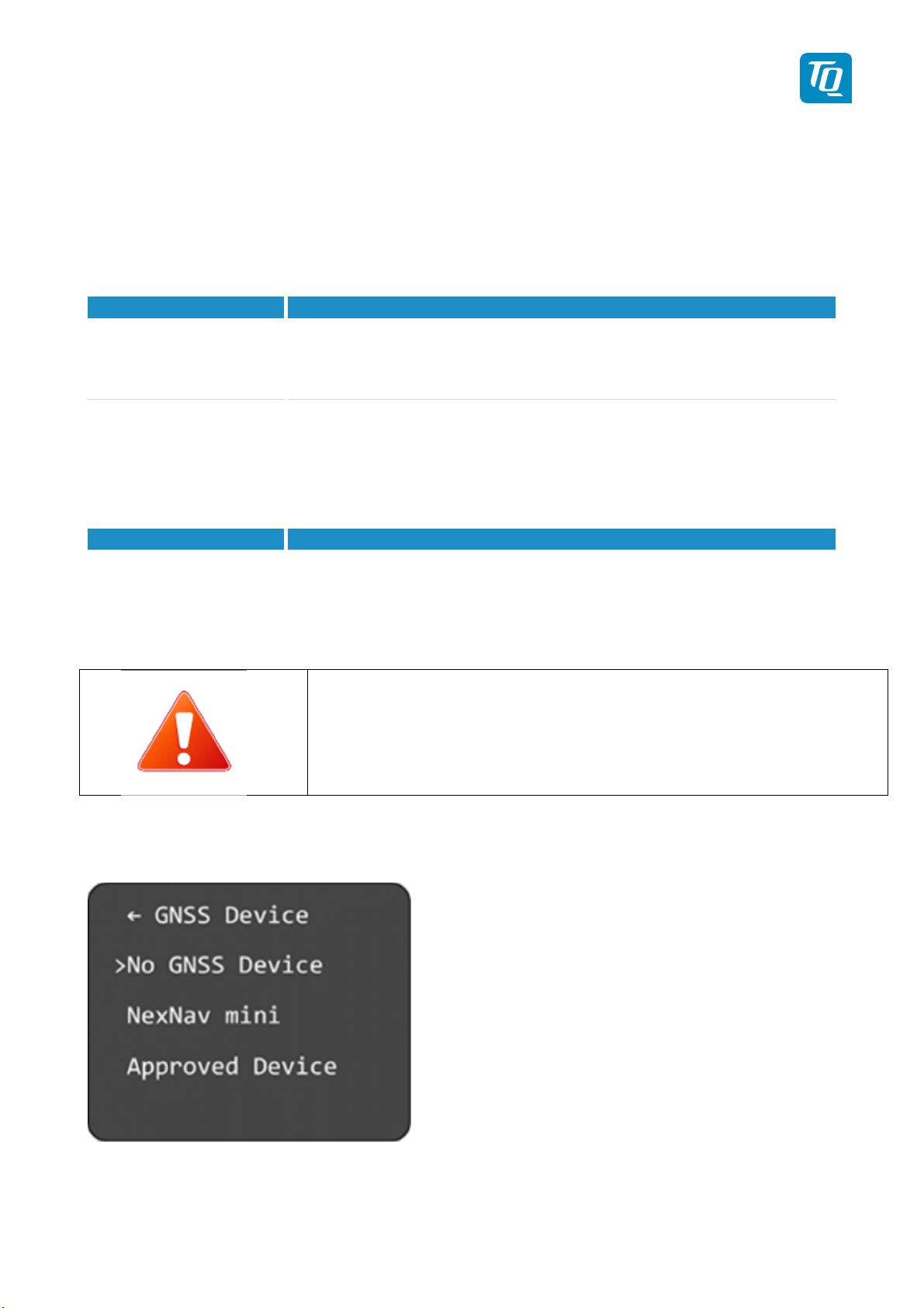
To configure the GNSS Device select “Select GNSS Device" and press the rotary knob. A submenu
“GNSS Device” is displayed.
Figure 30: GNSS Device Selection Menu
KTX2-F.A-MAN.0001.docx Page 42 of 74
© TQ-Systems GmbH. All information contained in this documents have to be treated strictly confidential. The transfer of presentations and know-how to third parties
requires the prior written consent of TQ-Systems GmbH.
Page 43
GNSS Device
Explanation
A NexNav mini device is used.
Approved Device
A recommended
TQ Aviation KTX2-F.0100
EASA.AP445 MAN
Turn the rotary switch to select the desired GNSS device and press the rotary knob to confirm.
No GNSS Device No WAAS GNSS device is used. The ADS-B function is disabled.
NexNav mini
NMEA WAAS GNSS device is used. The device must
The ADS-B function is enabled.
support at least the $GxRMC-sentence (as defined in the NMEA 0183
protocol). The ADS-B function is enabled.
Table 5: List of supported GNSS Devices
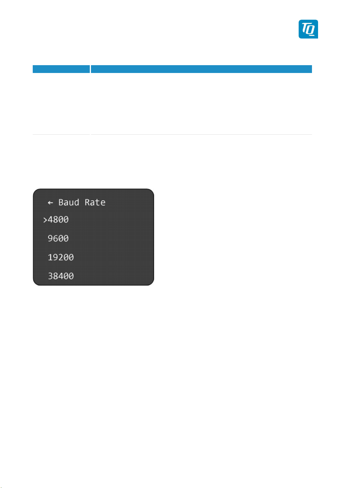
If an “Approved Device” is selected a submenu is displayed for configuring the baud rate.
Turn the rotary switch to select the appropriate baud rate and press the rotary knob to confirm.
Figure 31: Baud Rate Selection Menu
KTX2-F.A-MAN.0001.docx Page 43 of 74
© TQ-Systems GmbH. All information contained in this documents have to be treated strictly confidential. The transfer of presentations and know-how to third parties
requires the prior written consent of TQ-Systems GmbH.
Page 44
TQ Aviation KTX2-F.0100
EASA.AP445 MAN
3.4.2.1.3.5 Select Length/Width
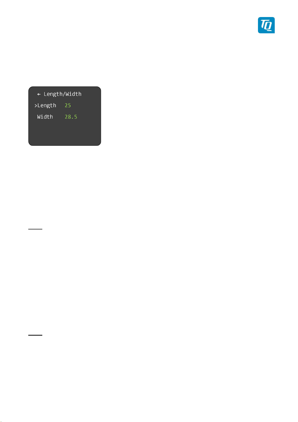
On the ground, ADS-B transmits encoded aircraft size information which is used by ATC to identify
taxiing routes and potential conflicts.
To configure the length and width of the aircraft select “Length/Width" and press the rotary knob. A
submenu “Length/Width” is displayed.
Figure 32: Aircraft Length/Width Configuration Menu
To configure the length of the aircraft perform the following procedure:
1. Select “Length" and press the rotary knob. The first digit of the length value turns yellow.
2. Turn the rotary knob to change the value.
3. Press the rotary knob again to save the selected digit. The next digit turns yellow.
4. Turn the rotary knob to change the value.
5. Press the rotary knob again to save the selected digit. The length value turns green.
Note:
The aircraft length has to be entered in meters rounded to next full meter.
E.g.: If the length is 7.2 m, the value must be 08.
To configure the width of the aircraft (wingspan) perform the following procedure:
1. Select “Width" and press the rotary knob. The first digit of the width value turns yellow.
2. Turn the rotary knob to change the value.
3. Press the rotary knob again to save the selected digit. The next digit turns yellow.
4. Turn the rotary knob to change the value.
5. Press the rotary knob again to save the selected digit. The next digit turns yellow.
6. Turn the rotary knob to change the value.
7. Press the rotary knob again to save the selected digit. The width value turns green.
Note:
The aircraft width has to be entered in meters rounded to the next 1/10 meter.
E.g.: If the width is 9.31 m, the value must be 09.4
KTX2-F.A-MAN.0001.docx Page 44 of 74
© TQ-Systems GmbH. All information contained in this documents have to be treated strictly confidential. The transfer of presentations and know-how to third parties
requires the prior written consent of TQ-Systems GmbH.
Page 45
TQ Aviation KTX2-F.0100
EASA.AP445 MAN
3.4.2.1.3.6 GNSS Antenna Offset
The GNSS antenna offset is used together with the aircraft length and width to manage taxiway conflicts.
Within the GNSS antenna offset menu, the longitudinal and lateral position offset of the GNSS antenna
can be entered. While mainly important for large aircraft, the values can be entered for small aircraft as
well.
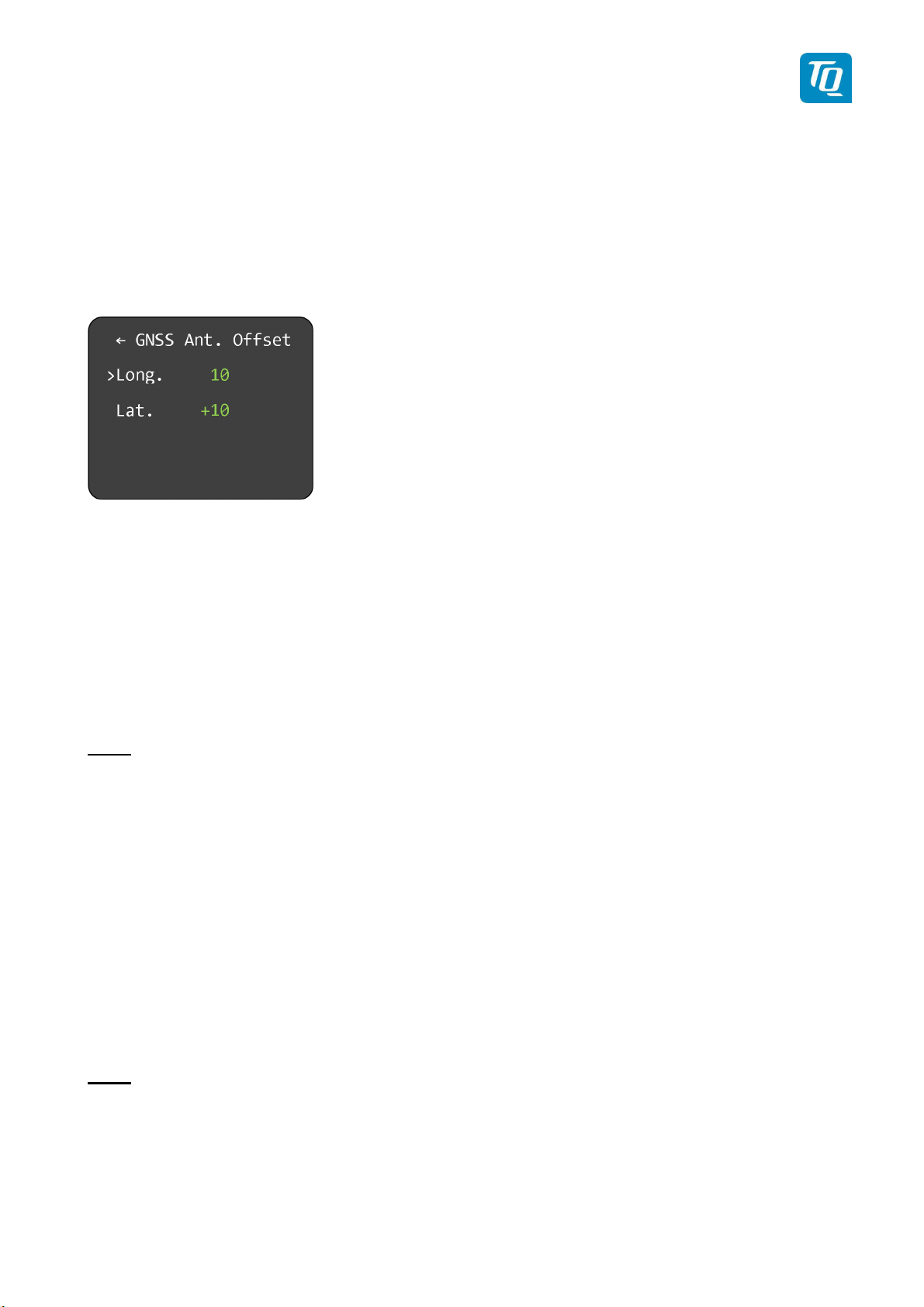
To configure the GNSS antenna offset select “GNSS Ant. Offset” and press the rotary knob. A submenu
“GNSS Ant. Offset” is displayed.
Figure 33: GNSS Antenna Offset Configuration Menu
To configure the longitudinal offset of the GNSS antenna perform the following procedure:
1. Select “Long." and press the rotary knob. The first digit of the offset value turns yellow.
2. Turn the rotary knob to change the value.
3. Press the rotary knob again to save the selected digit. The next digit turns yellow.
4. Turn the rotary knob to change the value.
5. Press the rotary knob again to save the selected digit. The offset value turns green.
Note:
The longitudinal offset has to be entered in meters measured from the nose of the aircraft.
E.g.: If the offset is 3.2 m, the value must be 04.
To configure the lateral offset of the GNSS antenna perform the following procedure:
1. Select “Lat." and press the rotary knob. The “+/-“ sign of the offset value turns yellow.
2. Turn the rotary knob to change the sign.
3. Press the rotary knob again to save sign value. The first digit of the offset value turns yellow.
4. Turn the rotary knob to change the value.
5. Press the rotary knob again to save the selected digit. The next digit turns yellow.
6. Turn the rotary knob to change the value.
7. Press the rotary knob again to save the selected digit. The offset value turns green.
Note:
For most small aircraft a value of “00” is adequate. In case an antenna offset is applicable, the position to
the left side of the aircraft will require a negative sign, to the right a positive sign. The lateral offset has to
be entered in meters measured from longitudinal (Roll) axis of the aircraft.
E.g.: If the offset is 1.3 m to left side, the value must be -02.
KTX2-F.A-MAN.0001.docx Page 45 of 74
© TQ-Systems GmbH. All information contained in this documents have to be treated strictly confidential. The transfer of presentations and know-how to third parties
requires the prior written consent of TQ-Systems GmbH.
Page 46
TQ Aviation KTX2-F.0100
EASA.AP445 MAN
3.4.2.1.4 Save Flight ID
To save a Flight ID configuration select “Save” and press the rotary knob. The “Flight ID” menu for
adding, modifying and deleting a Flight ID configuration will be displayed after the configuration is saved.
3.4.2.2 Modify Flight IDs
To modify a Flight ID select “Modify” and press the rotary knob. A submenu “Select FID” is displayed.
See 3.4.2.4 for details.
After the desired Flight ID is selected the submenu “Edit FID Param.” is displayed and the parameters of
the Flight ID can be modified (see 3.4.2.1).
3.4.2.3 Delete Flight IDs
To delete a Flight ID select “Delete” and press the rotary knob. A submenu “Select FID” is displayed.
See 3.4.2.4 for details.
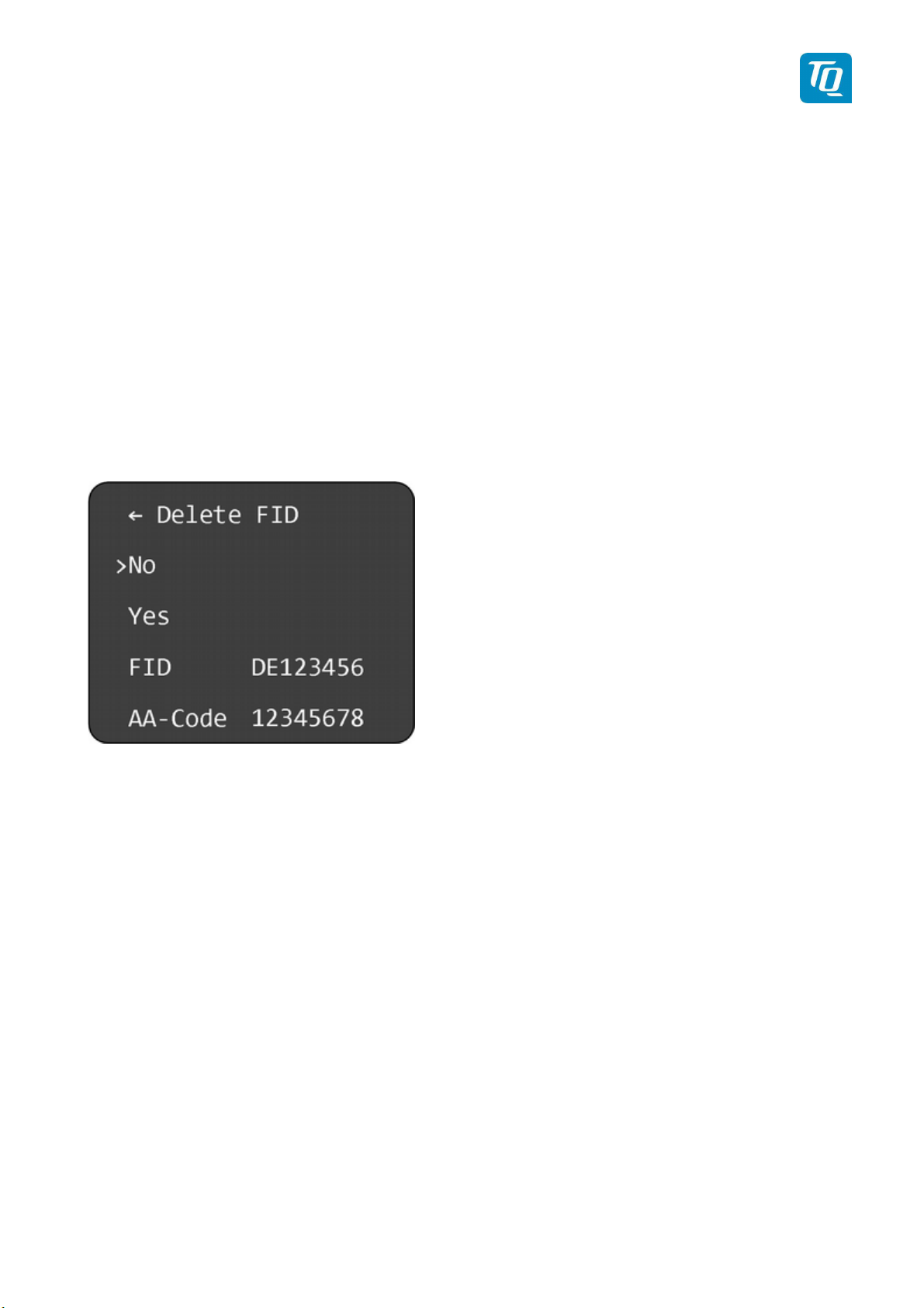
After the desired Flight ID is selected the submenu “Delete FID” is displayed.
Figure 34: Delete Flight ID Menu
To delete the Flight ID turn the rotary knob to select “Yes” and press the rotary knob. The Flight ID is
deleted and the “Flight ID” menu is displayed.
If you select “No” and press the rotary knob the Flight ID is not deleted and the “Flight ID” menu is
displayed.
The “FID” and “AA-Code” are only displayed for information purposes.
3.4.2.4 Multiple Flight IDs
In case multiple Flight IDs are configured a selection menu is displayed where necessary.
The selection menu for multiple Flight IDs allows the selection of an already configured Flight ID (see
3.4.2.1) for the operation or configuration of the transponder. The selection menu may consist of two
pages (see note below).
KTX2-F.A-MAN.0001.docx Page 46 of 74
© TQ-Systems GmbH. All information contained in this documents have to be treated strictly confidential. The transfer of presentations and know-how to third parties
requires the prior written consent of TQ-Systems GmbH.
Page 47
TQ Aviation KTX2-F.0100
EASA.AP445 MAN
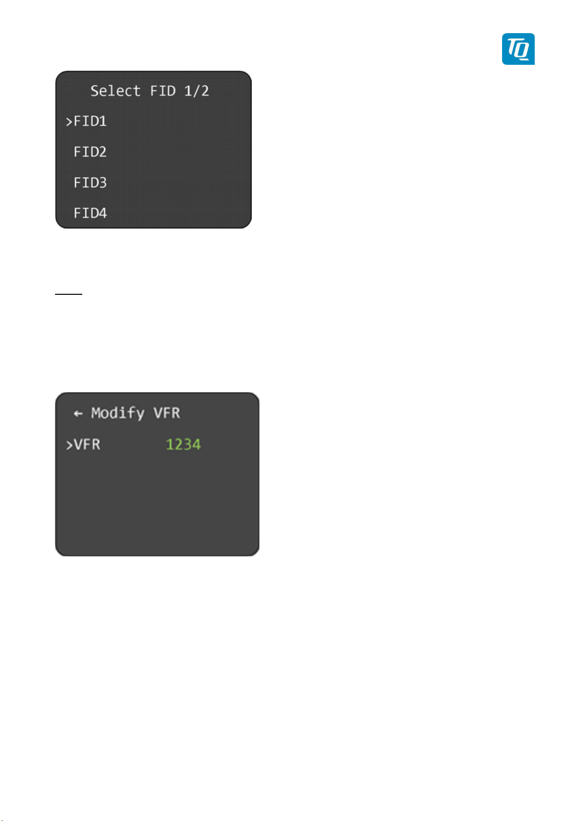
Figure 35: Multiple Flight ID Selection Menu
Turn the rotary knob to select the desired Flight ID. Press the rotary knob to confirm the selection. The
transponder will then use the selected configuration.
Note:
If more than four Flight IDs are configured turn the rotary knob clockwise until the next page is shown. To
go back to the previous page turn the rotary knob counterclockwise.
3.4.3 Modify VFR
To configure the VFR squawk code “Modify VFR" and press the rotary knob. A submenu “Modify VFR” is
displayed.
Figure 36: Modify VFR Code Menu
To change the VFR squawk code perform the following procedure:
1. Press the rotary knob. The first digit of the standby squawk turns yellow.
2. Turn the rotary knob to change the value.
3. Press the rotary knob again to save the selected digit. The next digit turns yellow.
4. Repeat steps 2 and 3 until all four (4) digits are set to desired VFR squawk code.
KTX2-F.A-MAN.0001.docx Page 47 of 74
© TQ-Systems GmbH. All information contained in this documents have to be treated strictly confidential. The transfer of presentations and know-how to third parties
requires the prior written consent of TQ-Systems GmbH.
Page 48

TQ Aviation KTX2-F.0100
EASA.AP445 MAN
Note:
Make sure, that you enter the correct VFR squawk code for the particular country where your aircraft is
operated.
Examples:
Germany: VFR Squawk = 7000
USA: VFR Squawk = 1200
KTX2-F.A-MAN.0001.docx Page 48 of 74
© TQ-Systems GmbH. All information contained in this documents have to be treated strictly confidential. The transfer of presentations and know-how to third parties
requires the prior written consent of TQ-Systems GmbH.
Page 49
TQ Aviation KTX2-F.0100
EASA.AP445 MAN
3.4.4 Factory Reset
In certain cases it may be necessary to perform a factory reset. Performing a factory reset will reset all
settings to their factory defaults.
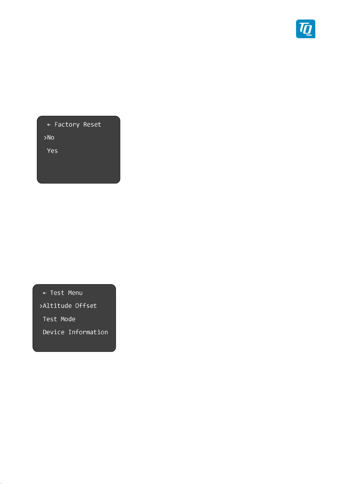
To perform a factory reset select “Factory Reset” and press the rotary knob. A submenu “Factory Reset”
is displayed.
Figure 37: Factory Reset Menu
To perform a factory reset turn the rotary knob to select “Yes” and press the rotary knob. A notification is
displayed which requests a restart of the transponder.
3.4.5 Test Menu
The second page of the setup menu contains only the test menu.
To enter the test menu select “Test Menu” and press the rotary knob. A submenu “Test Menu” is
displayed.
Figure 38: Test Menu
To calibrate the altitude offset select “Altitude Offset” and press the rotary knob. A submenu “Altitude
Offset” is displayed (see 3.4.5.1).
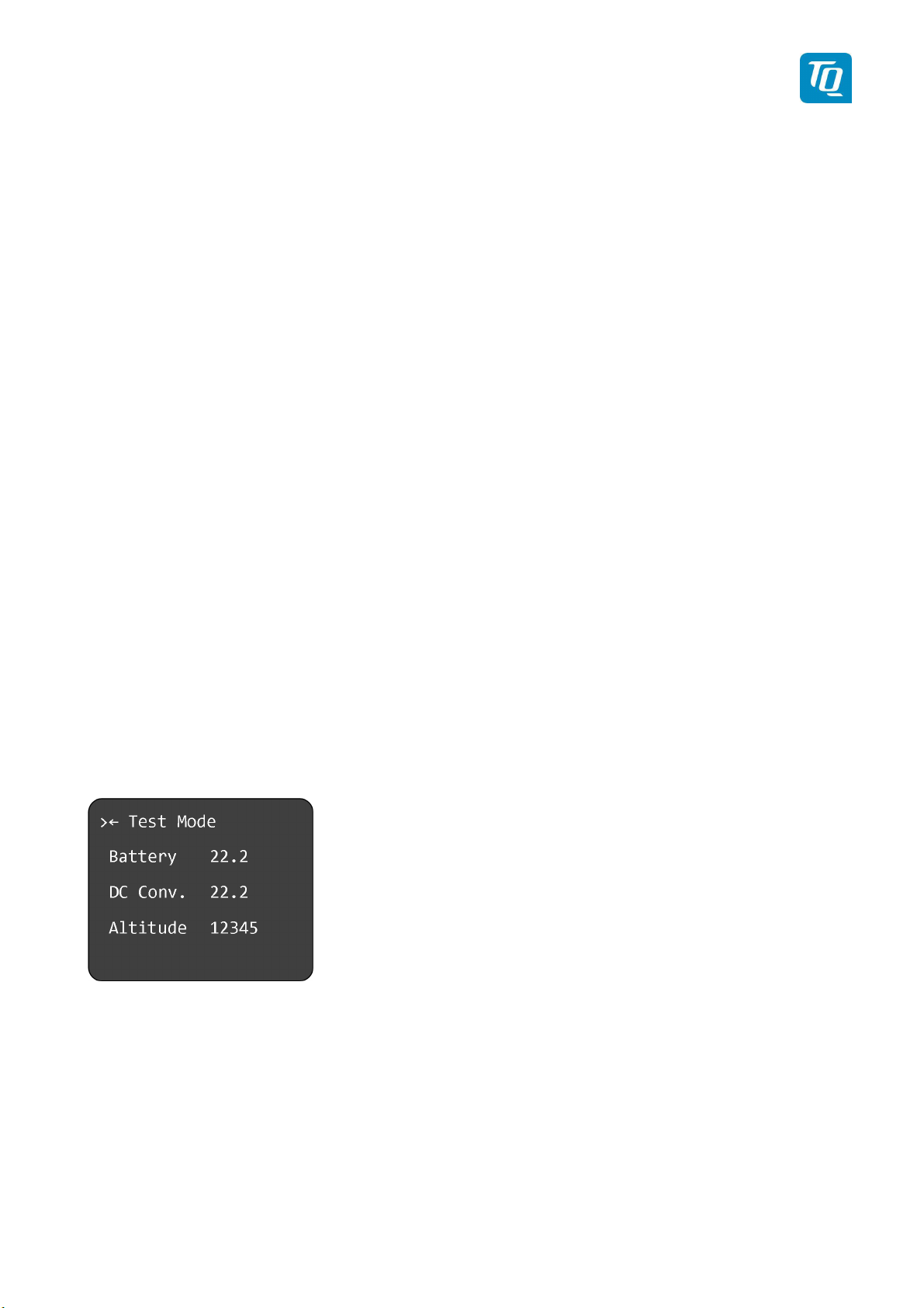
To enter the test mode select “Test Mode” and press the rotary knob. A submenu “Test Mode” is
displayed (see 3.4.5.2).
To show some device information select “Device Information” and press the rotary knob. A submenu
“Device Info” is displayed (see 3.4.5.3).
KTX2-F.A-MAN.0001.docx Page 49 of 74
© TQ-Systems GmbH. All information contained in this documents have to be treated strictly confidential. The transfer of presentations and know-how to third parties
requires the prior written consent of TQ-Systems GmbH.
Page 50
TQ Aviation KTX2-F.0100
EASA.AP445 MAN
3.4.5.1 Altitude Offset Calibration
The Altitude Offset Calibration allows you to adjust the built-in altitude encoder to ensure that the flight
level transmitted by the transponder complies with all relevant standards.
This process is normally carried out every 24 months, as part of the altimeter checks on the aircraft. The
maximum allowed difference between the primary altimeter and the altitude encoder is 125 feet
according to ETSO C88a.
The altitude encoder in the transponder is extremely accurate, has an excellent long-term stability and is
accurately calibrated during manufacture. But it is possible that a combination of allowed accuracy
deviations in the altitude encoder and the primary altimeter may show an altitude difference exceeding
125 feet. In that case it is recommend to perform an altitude offset calibration.
3.4.5.1.1 Calibration Equipment
To perform the altitude offset calibration the transponder needs to be powered up. Additionally a pitot
static test set is needed together with the appropriate adapters to connect to the static port on the
aircraft. The pitot static test set should be able to drive the altitude from sea level to above the service
ceiling of the aircraft.
Note:
For the calibration procedure no transponder test set is required. During the calibration procedure all
necessary information is displayed. Nevertheless a transponder test set can be used to verify the
transmissions of the transponder.
3.4.5.1.2 Calibration Procedure
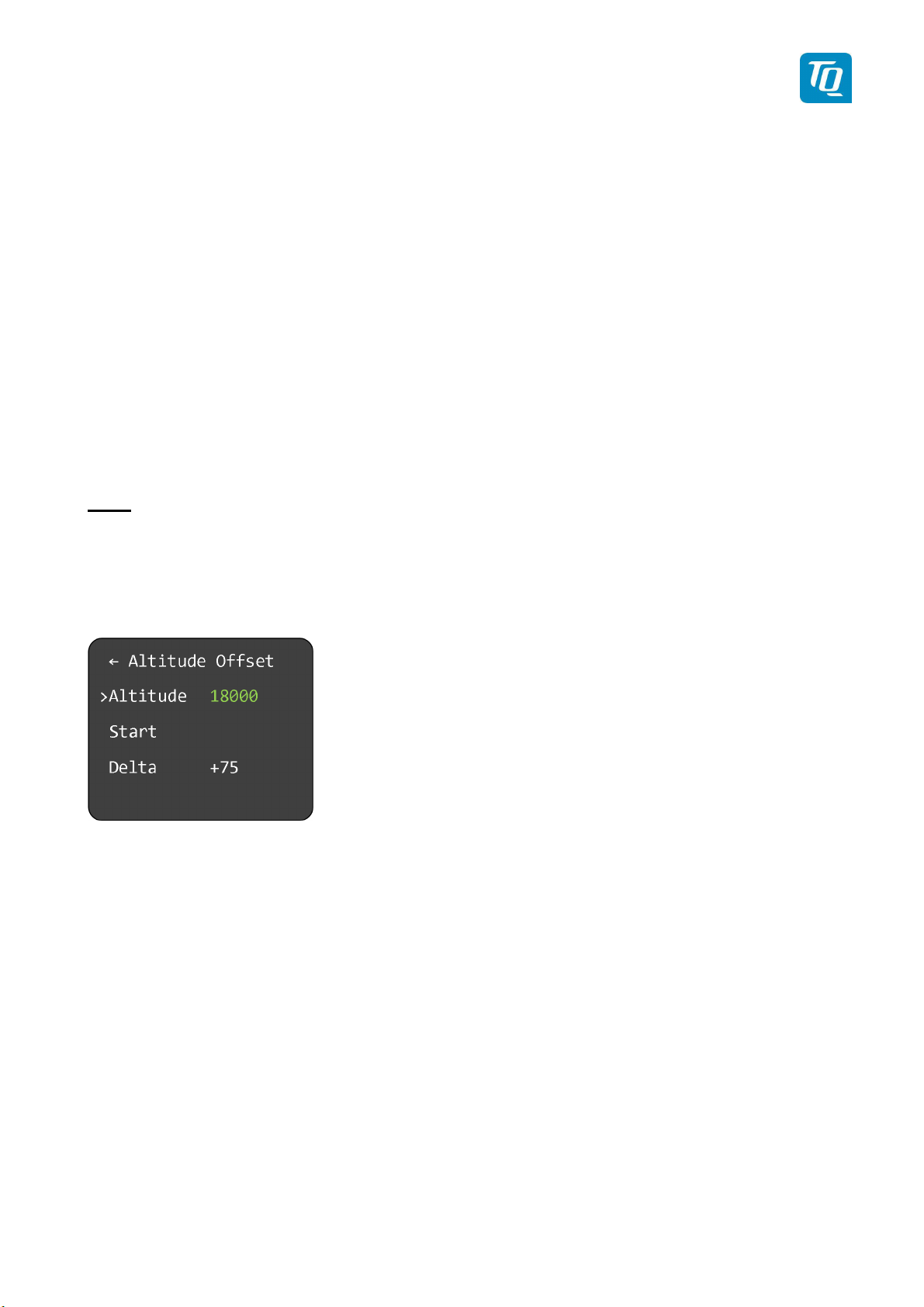
Figure 39: Altitude Offset Calibration Menu
To perform the altitude offset calibration perform the following procedure:
1. Select “Altitude” and press the rotary knob. The first digit of the altitude set point turns yellow.
2. Turn the rotary knob to change the value.
3. Press the rotary knob again to save the selected digit. The next digit turns yellow.
4. Repeat steps 2 and 3 until all digits are set to desired altitude set point.
Note: It is recommended to use 18000 ft as altitude set point.
5. On the pitot static test set drive the altitude to the set point value as entered before and wait until
the pressure has stabilized.
6. Select “Start” and press the rotary knob. The calibration procedures is started. During the “Delta”
value shows three dashes (“---“).
KTX2-F.A-MAN.0001.docx Page 50 of 74
© TQ-Systems GmbH. All information contained in this documents have to be treated strictly confidential. The transfer of presentations and know-how to third parties
requires the prior written consent of TQ-Systems GmbH.
Page 51
TQ Aviation KTX2-F.0100
EASA.AP445 MAN
7. After a few seconds either the “Delta” value is showing the altitude offset value or a notification is
displayed.
In a normal case the calibration procedure was successfully performed and the new altitude offset
value is stored.
In a rare case the offset value determined by the calibration procedure is beyond the limits.
Possible reasons can be:
• Altitude set point values of transponder and static test set do not match.
=> Check the settings.
• Failure in the static port connection from the static test set to the transponder.
=> Check the installation.
• Failure of the altitude encoder.
=> Send the unit for servicing.
To verify the altitude measurement the following procedure must be performed:
1. Switch off the transponder.
2. Switch on the transponder in “Setup Mode” and enter the “Test Mode” (see 3.4.5.2).
3. On the pitot static test set drive the altitude to -1000 feet.
4. Verify that the altitude displayed on the transponder correspond within the 125 foot tolerance.
Additionally verify the altitude value transmitter by the transponder.
5. Repeat this procedure for all altitudes to the service ceiling of the aircraft in steps of 1000 feet.
3.4.5.2 Test Mode
The submenu “Test Mode” displays the following internal measurements:
• Operating voltage (Battery)
• DC Converter voltage (power supply for the transmitter)
• Altitude (in feet)
Figure 40: Test Mode Menu
3.4.5.3 Device Info
The submenu “Device Info” displays the checksum of the software and the serial number of the device.
KTX2-F.A-MAN.0001.docx Page 51 of 74
© TQ-Systems GmbH. All information contained in this documents have to be treated strictly confidential. The transfer of presentations and know-how to third parties
requires the prior written consent of TQ-Systems GmbH.
Page 52

TQ Aviation KTX2-F.0100
EASA.AP445 MAN
Figure 41: Device Info Menu
KTX2-F.A-MAN.0001.docx Page 52 of 74
© TQ-Systems GmbH. All information contained in this documents have to be treated strictly confidential. The transfer of presentations and know-how to third parties
requires the prior written consent of TQ-Systems GmbH.
Page 53
TQ Aviation KTX2-F.0100
EASA.AP445 MAN
4. Errors, Warnings and Notifications
The transponder distinguishes 3 types of faults:
• Degrading failures
• Limiting failures
• Severe failures
Additionally notifications are displayed where appropriate.
In order to be serviced, a defective transponder needs to be shipped to the nearest service station. For
addresses see the TQ General Aviation website:
https://www.tq-general-aviation.com/en/Service
4.1
Degrading failures
If a degrading failure is detected the transponder continues to operate. But its performance may be
reduced. Once detected a warning message is displayed. This message can be confirmed by pressing
the rotary knob. The normal operation display will be shown again with the failure indication.
To handle a nonrecurring cause the transponder can be switched off and
on again. If the error reoccurs the transponder can be operated as usual
but with reduced performance.
Note:
Only the last failure is shown except for the battery voltage warning.
KTX2-F.A-MAN.0001.docx Page 53 of 74
© TQ-Systems GmbH. All information contained in this documents have to be treated strictly confidential. The transfer of presentations and know-how to third parties
requires the prior written consent of TQ-Systems GmbH.
Page 54
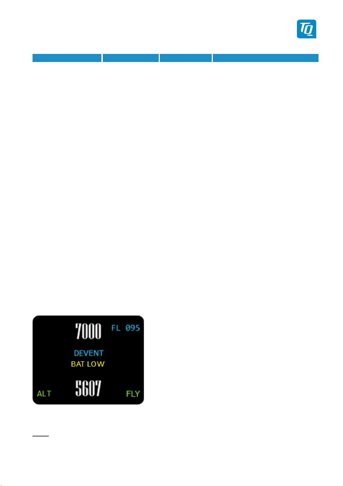
Failure
Explanation
Degradation
Action / Remark
Antenna VSWR is
Very low battery voltage
TQ Aviation KTX2-F.0100
EASA.AP445 MAN
The following table shows a list of all degrading failures of the transponder.
DC converter TX supply voltage
is low
Bad antenna
bad (very high)
Transmitter weak TX output power is
too low
Flight Level The altimeter
reports a failure
TX output power
is reduced.
TX output power
is reduced.
TX output power
is reduced.
No barometric
altitude
information is
sent.
Send unit for servicing.
Check antenna installation (cable,
connectors etc.) to resolve the
problem before next flight.
If no root cause can be discovered,
send unit for servicing.
Check antenna installation (cable,
connectors etc.) to resolve the
problem before next flight.
If no root cause can be discovered,
send unit for servicing.
Check connection and function of
static air port to resolve the problem
before next flight.
If no root cause can be discovered,
send unit for servicing.
Low battery voltage Battery voltage is
See below. See below.
below 11 Volts
Battery voltage is
See below. See below.
below 7.5 Volts
Table 6: Degrading Failures
4.1.1 Low Battery Voltage
If the supply voltage of the transponder falls below 11 V DC, a yellow indication “BAT LOW” is shown in
the center of the display. The indication is shown as long as the voltage is too low.
Figure 42: Low Battery Voltage
Note:
The transponder is designed to operate above 9 V DC. Do not operate the unit below 9 volts.
KTX2-F.A-MAN.0001.docx Page 54 of 74
© TQ-Systems GmbH. All information contained in this documents have to be treated strictly confidential. The transfer of presentations and know-how to third parties
requires the prior written consent of TQ-Systems GmbH.
Page 55
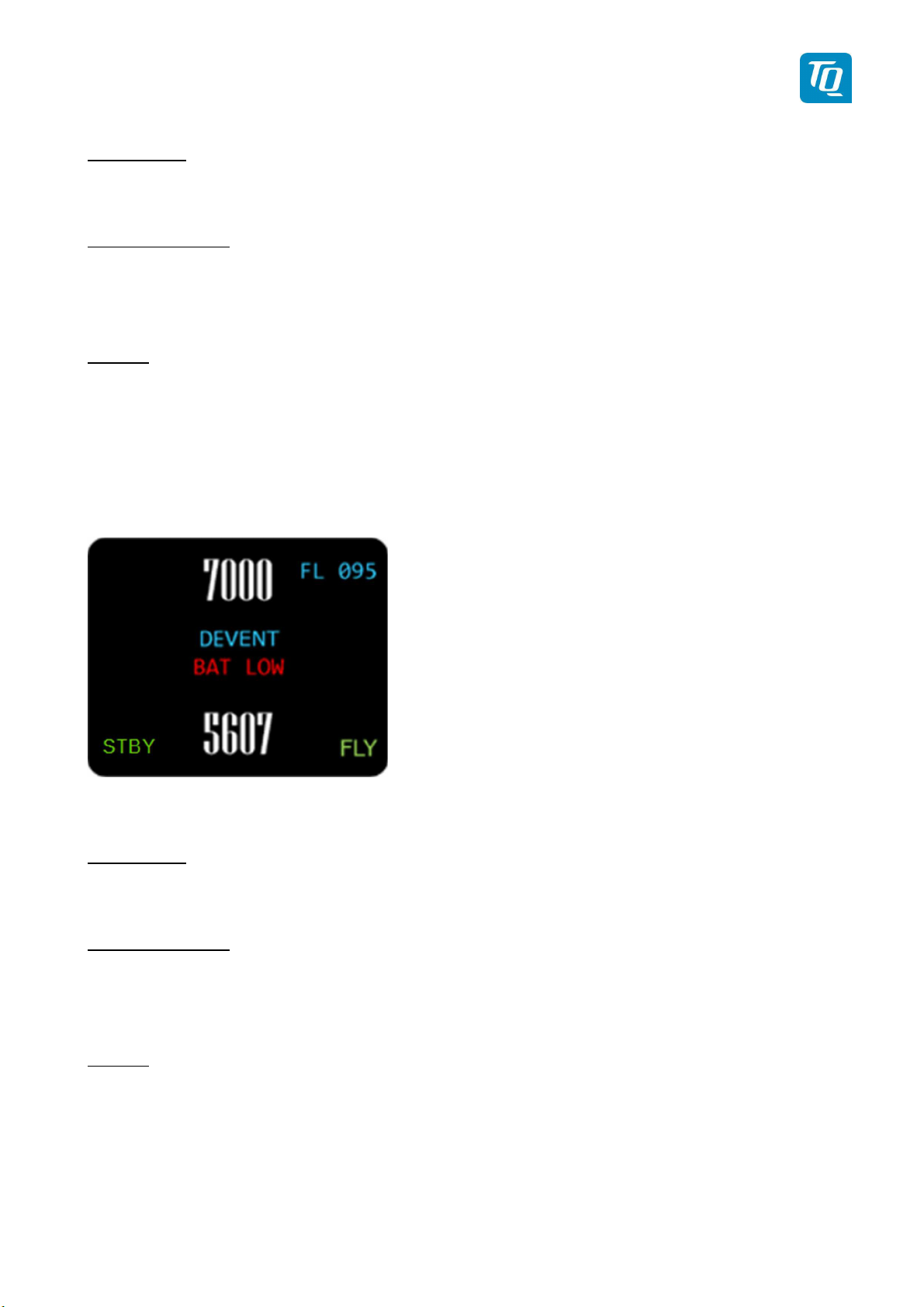
TQ Aviation KTX2-F.0100
EASA.AP445 MAN
Degradation:
TX output power may be reduced.
Possible Reasons:
1. Battery exhausted.
2. Voltage of electric generator is low.
Actions:
1. Exchange or charge the battery.
2. Check electric generator.
4.1.2 Very Low Battery Voltage
If the supply voltage of the transponder falls below 7.5 V DC, a red indication “BAT LOW” is shown in the
center of the display. The indication is shown as long as the voltage is too low.
Figure 43: Very Low Battery Voltage
Degradation:
Transponder is switched into “STBY” mode. No further operation possible.
Possible Reasons:
1. Battery exhausted.
2. Voltage of electric generator is very low.
Actions:
1. Exchange or charge the battery.
2. Check electric generator.
KTX2-F.A-MAN.0001.docx Page 55 of 74
© TQ-Systems GmbH. All information contained in this documents have to be treated strictly confidential. The transfer of presentations and know-how to third parties
requires the prior written consent of TQ-Systems GmbH.
Page 56
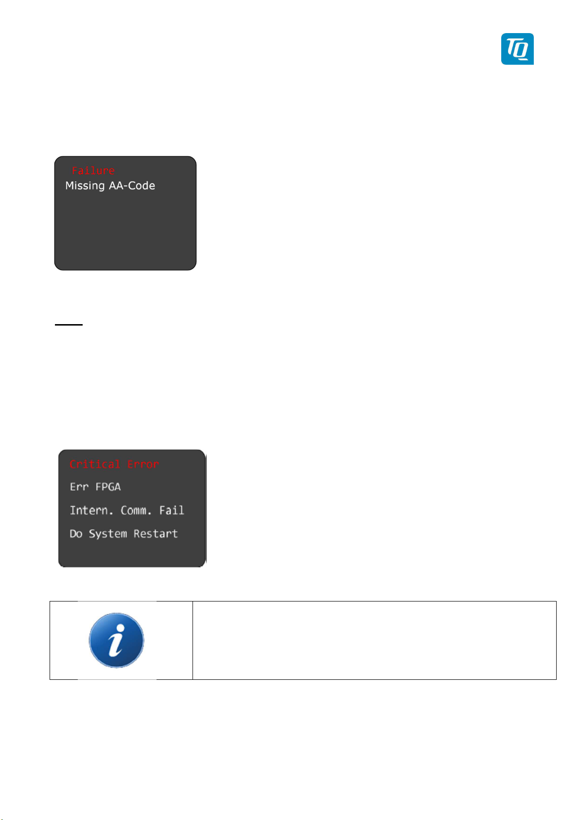
TQ Aviation KTX2-F.0100
EASA.AP445 MAN
4.2 Limiting failures
If no FID-Code (Flight ID) is entered or if the corresponding Aircraft Address (AA-Code) is missing or
incomplete, the following failure is displayed after switching on the transponder:
Figure 44: Missing AA-Code
To fix this error an appropriate FID and AA-Code has to be configured as described in chapter 3.4.2.
Note:
This message can be cleared by pressing the rotary knob. The transponder will then operate in A/C
mode only.
4.3 Severe failures
In case a severe failure is detected, a message (example) as shown below is displayed. No further
operation of the transponder is possible. No replies will be made to interrogations and ADS-B out is
switched off.
Figure 45: Critical Error (Example)
To handle a nonrecurring cause the transponder can be switched off and
on again. But if the error reoccurs the transponder must be switched off.
KTX2-F.A-MAN.0001.docx Page 56 of 74
© TQ-Systems GmbH. All information contained in this documents have to be treated strictly confidential. The transfer of presentations and know-how to third parties
requires the prior written consent of TQ-Systems GmbH.
Page 57

Displayed Error
Explanation
Remarks
Severe operation error. No access
Severe operation error. No access
ADC
operation error. No access
Severe operation error. No or very
Antenna failure
TQ Aviation KTX2-F.0100
EASA.AP445 MAN
The following table shows a list of all degrading failures of the transponder.
EEPROM access
to EEPROM.
FPGA
communication
FPGA internal Severe operation error. FPGA
Severe
Trans. out. power
MCU Severe operation error. MCU
to FPGA.
internal failure.
to ADC.
low TX output power.
Severe operation error. Antenna
not connected or Antenna VSWR
is very high.
internal failure.
Send unit for servicing.
Send unit for servicing.
Send unit for servicing.
Send unit for servicing.
Check installation (power cable, antenna
cable, etc.). If no root cause can be
discovered, send unit for servicing.
Check installation (power cable, antenna
cable, etc.). If no root cause can be
discovered, send unit for servicing.
Send unit for servicing.
Unknown Error Severe operation error. Check installation (power cable, antenna
cable, etc.). If no root cause can be
discovered, send unit for servicing.
Table 7: Severe Failures
KTX2-F.A-MAN.0001.docx Page 57 of 74
© TQ-Systems GmbH. All information contained in this documents have to be treated strictly confidential. The transfer of presentations and know-how to third parties
requires the prior written consent of TQ-Systems GmbH.
Page 58
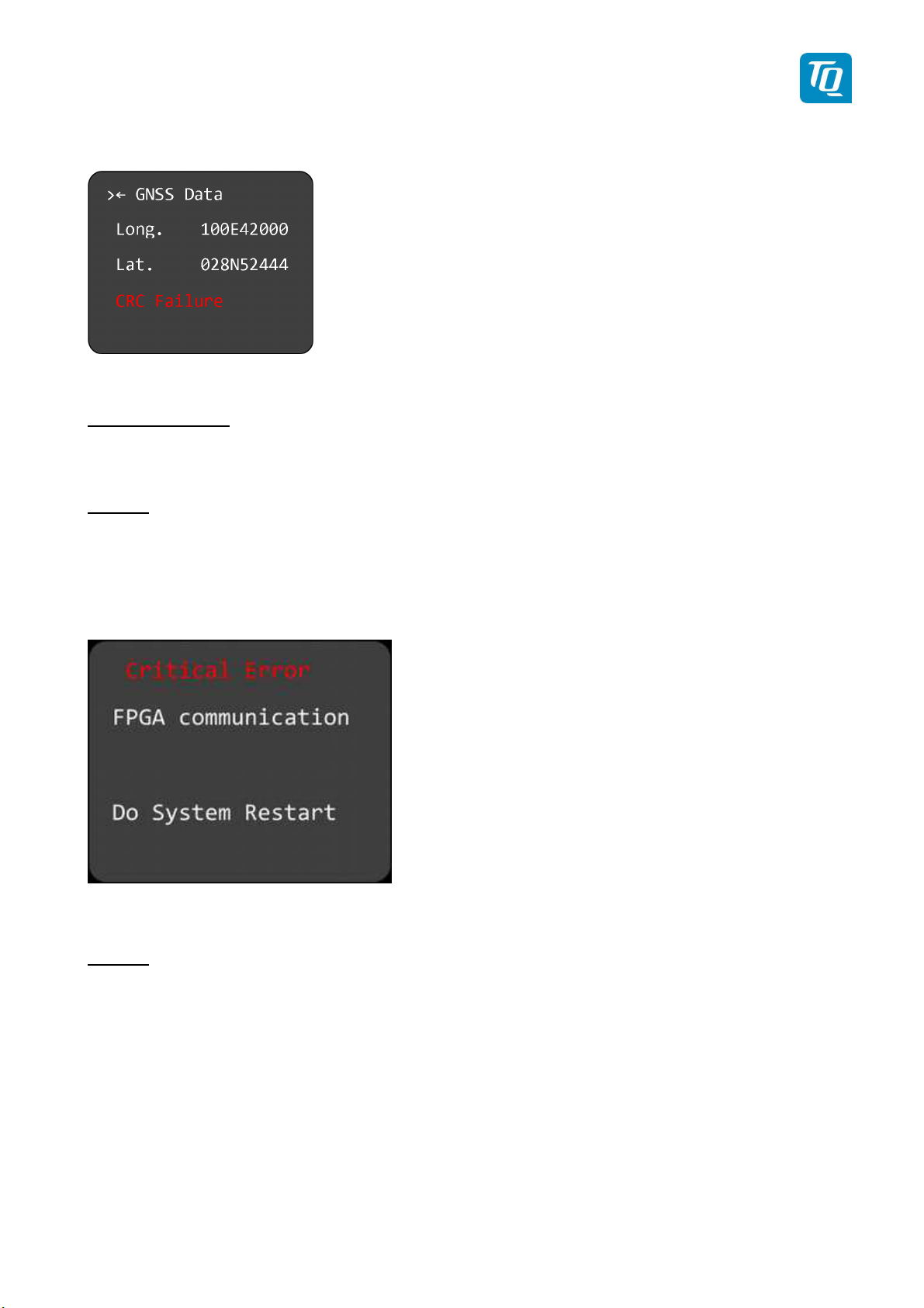
TQ Aviation KTX2-F.0100
EASA.AP445 MAN
4.4 Notifications
4.4.1 GNSS Data CRC Failure
Figure 46: GNSS CRC Failure
Possible Reasons:
Invalid data from GNSS source.
Actions:
Check installation, cable, connections and configuration of the installed GNSS source.
4.4.2 Do System Restart
The following message is displayed if a restart of transponder is necessary.
Figure 47: System Restart
Actions:
Switch the transponder off and on again
KTX2-F.A-MAN.0001.docx Page 58 of 74
© TQ-Systems GmbH. All information contained in this documents have to be treated strictly confidential. The transfer of presentations and know-how to third parties
requires the prior written consent of TQ-Systems GmbH.
Page 59
TQ Aviation KTX2-F.0100
EASA.AP445 MAN
5. Installation
5.1 Equipment Connections
5.1.1 Electrical Connections
The 15pin D-SUB connector at the rear side of the unit includes all electrical connections, except for the
antenna, see chapter 5.2.2 for details.
The positive supply line needs to be protected by a 3A slow blow
fuse!
The transponder should be connected to an uninterruptible power supply
as short power interrupts may cause the transponder to restart in “STBY”
Mode or in Multiple Flight ID selection.
5.1.2 Mutual Suppression
Other equipment
on board
(e.g.
DME)
may transmit in the same frequency band as the transponder. If
such a device is installed a single wire bus (Suppression = active at +12V) must be installed in order to
protect the receiving parts of the different devices from in-band transmissions.
Mutual suppression is a pulse that is sent to the other equipment to suppress transmission of a
competing transmitter for the duration of the pulse train transmission. The transponder transmission may
be suppressed by an external source and vice versa.
To activate mutual suppression the SUPP_I/O requires a +12V source from the other equipment, see
chapter 5.2.2.
All equipment connected to the suppression line must be re-inspected and
reapproved from a qualified avionic technician before operation.
Use only shielded lines.
5.1.3 Ground Switch
If a Ground Switch is connected (and activated in the Setup), the transponder is enabled to distinguish
between weight-on-wheel (On the Ground) and no-weight-on-wheel (In-Flight) conditions. In the weighton-wheel condition the transponder automatically enters the Standby mode.
In order to complete this installation the input “FLY-GND“ must be connected to a switch, which connects
the input with “GND“ in case there is weight on wheels, or remains open during flight, see chapter 5.2.2.
KTX2-F.A-MAN.0001.docx Page 59 of 74
© TQ-Systems GmbH. All information contained in this documents have to be treated strictly confidential. The transfer of presentations and know-how to third parties
requires the prior written consent of TQ-Systems GmbH.
Page 60

TQ Aviation KTX2-F.0100
EASA.AP445 MAN
This option must additionally be activated in the Setup. For details on configuration please refer to
chapter 3.4.2.1.3.2.
5.1.4 Static Air Port
The transponder has a built-in altitude encoder which must be connected to the same source of static
pressure as the primary altimeter on the aircraft.
For this purpose the transponder has a hose connection at its rear side for nominal 5mm or 3/16 inch
tubing (inside diameter).
Connect the static air connection to the static pressure port and ensure a tight connection with a suitable
hose clamp.
5.1.5 GNSS Interface
A GNSS source can be connected to the serial interface (RS232) providing GNSS position data for use
of ADS-B out.
Requirements:
• Required GNSS hardware:
o NexNav Mini (Part-No. 21.000) which turns the transponder into a 14 CFR 91.227
compliant device as required for TC’d aircraft (FAA 2020 mandate).
or
o Standard NMEA0183 RMC data stream including the RMC-sub-format
(4800/9600/19200/38400 Baud) for aircrafts which do not require the ADS-B requirements
defined in 14 CFR 91.227.
• GNSS hardware needs to be connected to pin 13 (RX-RS232) and optionally pin 2 (TX-RS232)
of the D-SUB connector (see chapter 5.2.2). Power supply needs to be provided separately
considering the required operating voltage for the GNSS hardware.
The WAAS GNSS device needs to be selected in the setup menu (see chapter 3.1.4.4).
Note:
For connection to the NexNav Mini device, a proprietary cable is available from TQ. Please contact you
dealer for more information.
If a standard NMEA0183 WAAS GNSS source is sufficient for your aircraft (LSA, Experimental, Ultralight
etc.) you should consider brands recommended by TQ to avoid incompatibilities or malfunctions.
Note:
For correct function of the movement detection an update rate of 5 Hz is recommended for NMEA
devices.
5.1.6 Antenna Connector
The antenna is connected to a single coaxial connector (SMA) at the rear side of the transponder.
5.1.6.1 L-Band ADS-B Antennas
The L-Band antenna used with the KTX2 must fulfil to the following specifications:
KTX2-F.A-MAN.0001.docx Page 60 of 74
© TQ-Systems GmbH. All information contained in this documents have to be treated strictly confidential. The transfer of presentations and know-how to third parties
requires the prior written consent of TQ-Systems GmbH.
Page 61

Manufacturer
Part Number
Connector
Remarks
AV
TQ Aviation KTX2-F.0100
EASA.AP445 MAN
• Standard 50 Ω, vertically polarized antenna with a VSWR < 1.7:1 at 1090 MHz.
• TSO-C66( ), TSO-C74( ), TSO-C112( ) , or TSO-154c antennas that also meet the VSWR
specification.
Only the L-Band antennas listed in the table below have been tested for compatibility with transponder
installations.
Type
RAMI
Comant CI-105 BNC
Comant CI-105-11 TNC
Table 8: L-Band Antennas
5.1.6.2 Antenna Installation
The antenna should be installed according to the manufacturer’s instructions.
The following considerations should be taken into account for the antenna installation:
• The antenna should be placed not directly near any projections, the engine(s) and propeller(s). It
should also be placed not directly near landing gear doors, access doors or others openings
which will break the ground plane for the antenna.
• The antenna should be mounted on the bottom surface of the aircraft and in a vertical position
when the aircraft is in level flight.
• The antenna should not be mounted within 3 feet of the ADF sense antenna or any COMM
antenna and 6 feet from the transponder to the DME antenna.
-74 BNC
• Where practical, the antenna location should be chosen to keep the cable lengths as short as
possible and to avoid sharp bends in the cable to minimize the VSWR.
• To prevent RF interference, the antenna must be physically mounted at a minimum distance of 3
feet from the transponder.
Electrical connection to the antenna should be dust and water proof to avoid loss of efficiency as a result
of the presence of liquids or moisture. All antenna feeders must be installed in such a way that a
minimum of RF energy is radiated inside the aircraft.
5.1.6.3 Antenna Cable
The transponder is designed to fulfil the ADS-B Class 1 requirements allowing a maximum loss of 2 dB
in the connectors and cable used to connect it to the antenna. Exceeding this loss will degrade the
transmitter output power and receiver sensitivity.
A typical installation needs two (2) connectors at each end of the antenna cable.
Calculating a loss of 0.25dB for each connector allows a loss of 1.5dB for the cable itself.
An acceptable cable must have the following characteristics:
• Less than 1.5dB loss for the cable length needed.
• Characteristic impedance of 50 Ohms.
KTX2-F.A-MAN.0001.docx Page 61 of 74
© TQ-Systems GmbH. All information contained in this documents have to be treated strictly confidential. The transfer of presentations and know-how to third parties
requires the prior written consent of TQ-Systems GmbH.
Page 62

Cable Type
Max Length in
Insertion Loss
Remark
s
TQ Aviation KTX2-F.0100
EASA.AP445 MAN
• Double braid screens or a foil and braid screen.
Once the cable length from the transponder to the antenna is known, a cable type can be chosen which
has a loss per meter low enough to meet the above requirements (see table below).
Note:
Low loss cable typically uses foamed or cellular dielectrics and foil screens. These make such cables
especially prone to damage from too-tight bends or from momentary kinking during installation. Once
kinked, these cables do not return to full performance when straightened.
The following table is shows a list of some common cable types and the maximum usable lengths.
meters (feet)
dB/meter
(db/100ft)1
RG-400
M17/128-RG400
RG-304
M17/112-RG304
RG-393
M17/127-RG393
Carlisle IT Type
3C142B
Carlisle IT Type
311601
Carlisle IT Type
311501
Carlisle IT Type
311201
Carlisle IT Type
310801
2.5 (8’ 2”) 0.6 (18.5)
4.2 (13’ 9”) 0.36 (11.1)
5 (16’ 5”) 0.3 (9.2)
3.1 (10’ 2”) 0.48 (14.5)
5.2 (17’ 1”) 0.29 (8.7)
6.5 (21’ 4”) 0.23 (7.1)
8.3 (27’ 4”) 0.18 (5.6)
12.5 (41’) 0.12 (3.6)
Table 9: Common Antenna Cables
When routing the cable, ensure that you:
• Keep the cable length as short as possible.
• Avoid routing the cable round tight bends.
• Avoid kinking the cable, even temporarily during installation.
• Secure the cable so that it cannot interfere with other systems.
• Route the cable away from any heat sources.
1
RG type coaxial cable insertion loss can vary significantly between manufacturers. The insertion loss for RG type
cables shown in this column is considered 'worst case'. Refer to the cable manufacturer's specification sheet for
actual attenuation (insertion loss) for the cable being used.
KTX2-F.A-MAN.0001.docx Page 62 of 74
© TQ-Systems GmbH. All information contained in this documents have to be treated strictly confidential. The transfer of presentations and know-how to third parties
requires the prior written consent of TQ-Systems GmbH.
Page 63

TQ Aviation KTX2-F.0100
EASA.AP445 MAN
• Route the cable away from potential interference sources such as ignition wiring, 400Hz
generators, fluorescent lighting and electric motors.
• Allow a minimum separation of 300mm (12 inches) from an ADF antenna cable.
Note:
In case an already installed antenna can be further used (old transponder is replaced) and the existing
connector does not fit, it is recommended to replace the connector. Alternatively, an adapter from the
existing connector to a SMA male type connector can be used. But this will add an additional loss of
typical 0.1 – 0.2 dB to the installation which must be considered. If the total loss of 2 dB is exceeded the
cable must be replaced.
Note:
An SMA<->TNC adapter is available from TQ.
KTX2-F.A-MAN.0001.docx Page 63 of 74
© TQ-Systems GmbH. All information contained in this documents have to be treated strictly confidential. The transfer of presentations and know-how to third parties
requires the prior written consent of TQ-Systems GmbH.
Page 64
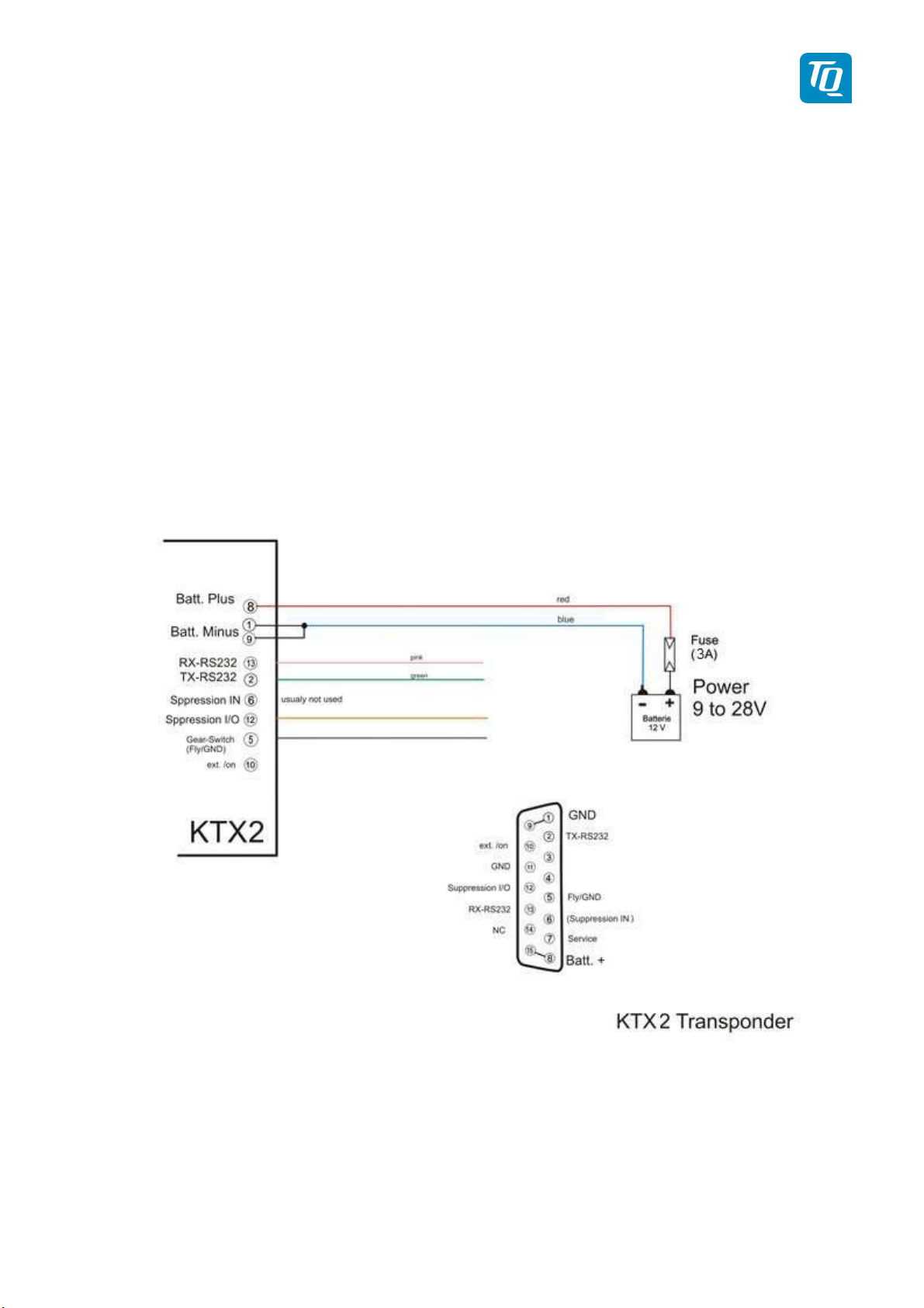
TQ Aviation KTX2-F.0100
EASA.AP445 MAN
5.2 Wiring
5.2.1 Conductor Cross Section
Power Supply (Batt. Plus, GND): AWG20 (0.62 mm²)
Signals:
AWG22 (0.38 mm²)
The conductors must be approved for aircraft use. Recommended Quality:
MIL-Spec 22759/34, (Spec 55) 20AWG / 22AWG
Crimped D-Sub connector is always preferred against soldered connectors. Original TQ harness comply
with common aviation wiring standards. Consult your approved aviation shop for installation details.
5.2.2 Wiring Scheme
Figure 48: Wiring
KTX2-F.A-MAN.0001.docx Page 64 of 74
© TQ-Systems GmbH. All information contained in this documents have to be treated strictly confidential. The transfer of presentations and know-how to third parties
requires the prior written consent of TQ-Systems GmbH.
Page 65
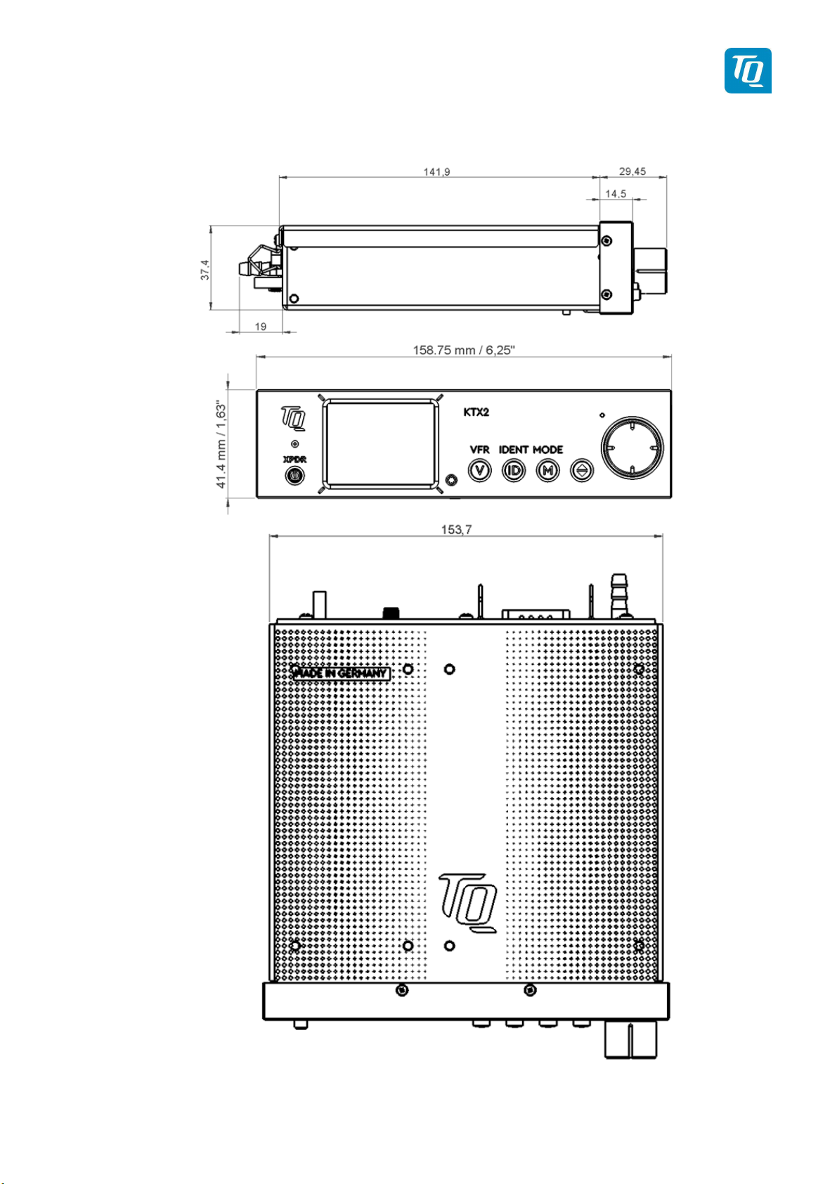
TQ Aviation KTX2-F.0100
EASA.AP445 MAN
6. Drawings
Figure 49: Dimensions of KTX2-F Standard round format
KTX2-F.A-MAN.0001.docx Page 65 of 74
© TQ-Systems GmbH. All information contained in this documents have to be treated strictly confidential. The transfer of presentations and know-how to third parties
requires the prior written consent of TQ-Systems GmbH.
Page 66
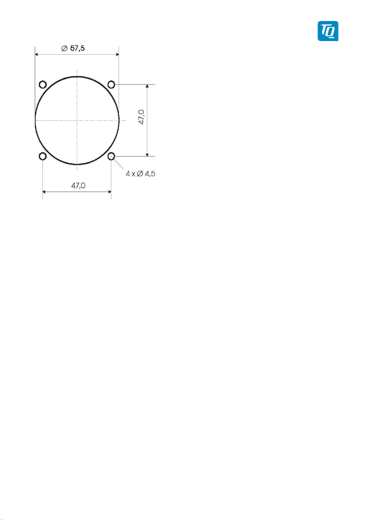
TQ Aviation KTX2-F.0100
EASA.AP445 MAN
Figure 50: Panel Cut-Out
KTX2-F.A-MAN.0001.docx Page 66 of 74
© TQ-Systems GmbH. All information contained in this documents have to be treated strictly confidential. The transfer of presentations and know-how to third parties
requires the prior written consent of TQ-Systems GmbH.
Page 67

TQ Aviation KTX2-F.0100
EASA.AP445 MAN
7. Technical Data
7.1 General
Designation
Authorization EASA.21O.10070633
Certification
Compliance
Dimensions KTX2-F
Weight KTX2-F 0.600 kg
ETSO-C112e / TSO-C112e
ETSO-C88b / TSO-C88b
ETSO-C166b_A3 / TSO-C166b
RTCA DO-181E /. ED-73E / Level 2els,Class 1
RTCA DO-178C/ ED-12C Level D
RTCA DO-254 / ED80 Level C
RTCA DO-160G / ED-14G
RTCA DO-260B / ED102A Class B1S
SAE AS8003
FCC ID: 2ANFF-KTX2F
158.75 x 41.4 x 190.35 +/- 1 mm
(6.25” x 1.63” x 7.5”)
pure housing
KTX2-F: cut-out dimensions
155 x 38 +/- 0.2 mm
Mounting
(6.1” x 1.5”)
installation depth
short frame: 140 +/- 0.2 mm (5.5”)
long frame: 236.4 +/- 0.2 mm (9.3”)
Temperature ranges:
Operation
Storage
-20 °C to +55 °C
-55 °C to +85 °C
Maximum flight level 30 000ft
Vibration DO-160G, Cat. S, Vibration Curve M
Humidity RTCA DO-160G, Cat. A
Shock
RTCA DO-160F ENV.
Category
6G
20G
[C4Z]CAB[SM]XXXXXXZ[BBB][AC]TB[B2F2]XXAX
operation
crash safety
Software Category ED-12C (RTCA DO-178C) Level C
Hardware Category DO-254 Level C
Power supply 9 V DC to 33V DC
KTX2-F.A-MAN.0001.docx Page 67 of 74
© TQ-Systems GmbH. All information contained in this documents have to be treated strictly confidential. The transfer of presentations and know-how to third parties
requires the prior written consent of TQ-Systems GmbH.
Page 68

Power consumption
•
TQ Aviation KTX2-F.0100
EASA.AP445 MAN
Designation
depending on the number of requests = 0.2 to
1.0A (@ 12V DC)
• Illumination 0.02A (@ 12V DC)
Fuse External fuse required: 3A, slow-blow
Compass security distance 300 mm (12”)
Table 10: Technical Data
KTX2-F.A-MAN.0001.docx Page 68 of 74
© TQ-Systems GmbH. All information contained in this documents have to be treated strictly confidential. The transfer of presentations and know-how to third parties
requires the prior written consent of TQ-Systems GmbH.
Page 69

TQ Aviation KTX2-F.0100
EASA.AP445 MAN
7.2 Transmitter – Receiver
TRANSMITTER
Reply transmission frequency 1090 ± 1MHz
≥ 54dBm (250 W) nominal at antenna connector,
RF Peak Power Output
≥ 51dBm (125 W) minimum at antenna base
(allowing 0.5dB connector loss and 1.5dB cable
loss)
Table 11: Transmitter Data
RECEIVER
Receiving frequency 1030 ± 1MHz
Receiver Characteristics:
Table 12: Receiver Data
General
ICAO 24-bit Aircraft Address
Squitter
Sensitivity
(Hex-Code)
Transmitted periodically at random intervals, full selfverification of data and occurrence
RF input power level resulting in a 90 % reply rate:
MTL for ATCRBS and ATCRBS/Mode S All-
Call interrogations: -74dBm ±3dB.
MTL for Mode S interrogations: -74dBm ±
3dB.
Aircraft Address as assigned by National
Aviation Authority
FID Flight ID: Flight Plan call sign or aircraft registration
marking
Pressure Altitude Up to 30 000ft in 25ft increments in-flight / on-ground
Flight Status Reports the available data and means by which the
transponder can report.
Table 13: General Data
KTX2-F.A-MAN.0001.docx Page 69 of 74
© TQ-Systems GmbH. All information contained in this documents have to be treated strictly confidential. The transfer of presentations and know-how to third parties
requires the prior written consent of TQ-Systems GmbH.
Page 70

TQ Aviation KTX2-F.0100
EASA.AP445 MAN
8. FCC related issues
8.1 Radiofrequency radiation exposure Information:
This transponder complies with FCC radiation exposure limits set forth for an uncontrolled
environment. This transponder should be installed and operated with minimum distance of 200
mm between the radiator and your body.
This transmitter must not be co-located or operating in conjunction with any other antenna or
transmitter.
Notice: This transponder has been tested and found to comply with the limits for a Class B
digital device, pursuant to Part 15 of the FCC Rules. These limits are designed to provide
reasonable protection against harmful interference in a residential installation. This transponder
generates, uses and can radiate radio frequency energy and, if not installed and used in
accordance with the instructions, may cause harmful interference to radio communications.
However, there is no guarantee that interference will not occur in a particular installation. If this
equipment does cause harmful interference to radio or television reception, which can be
determined by turning the equipment off and on, the user is encouraged to try to correct the
interference by one or more of the following measures:
• Reorient or relocate the receiving antenna.
• Increase the separation between the equipment and receiver.
• Connect the equipment into an outlet on a circuit different from that to which the receiver
is connected.
• Consult the dealer or an experienced radio/TV technician for help.
8.2 Compliance
Notice: This device complies with Part 15 of the FCC Rules and with Industry Canada license-
exempt RSS standard(s).
Operation is subject to the following two conditions:
(1) this transponder may not cause harmful interference, and
(2) this transponder must accept any interference received, including interference that
may cause undesired operation.
8.3 Modifications
Note:
Changes or modifications made to this transponder not expressly approved by TQ-Systems
GmbH may void the FCC authorization to operate this equipment.
KTX2-F.A-MAN.0001.docx Page 70 of 74
© TQ-Systems GmbH. All information contained in this documents have to be treated strictly confidential. The transfer of presentations and know-how to third parties
requires the prior written consent of TQ-Systems GmbH.
Page 71

TQ Aviation KTX2-F.0100
EASA.AP445 MAN
9. Maintenance
9.1 Periodic Maintenance
This transponder has been designed and manufactured to allow “on condition maintenance”. This means
that there are no periodic service requirements necessary to maintain continued airworthiness, and no
maintenance is required as long as it does properly perform its intended function. When service is
required, a complete performance test must be accomplished following any repair action. Repairs must
only be carried out in accordance with TQ-Systems GmbH service procedures.
9.2 Repair
Only exchange and flat repair of the equipment is permitted. In case of equipment malfunction, the unit
must be sent to the manufacturer. Refer to section “1.2 Customer Service”.
9.3 Cleaning
Clean the display only with, lint-free cloth and an eyeglass lens cleaner that is specified as safe for antireflective coatings.
KTX2-F.A-MAN.0001.docx Page 71 of 74
© TQ-Systems GmbH. All information contained in this documents have to be treated strictly confidential. The transfer of presentations and know-how to third parties
requires the prior written consent of TQ-Systems GmbH.
Page 72

TQ Aviation KTX2-F.0100
EASA.AP445 MAN
10. EXCLUSIVE LIMITED WARRANTY and LIMITATIONS ON LIABILITY
1. Our warranty and liability is based on legal provisions, provided nothing else has been agreed.
2. Delivery items may differ from product illustrations, especially in regard with color and weight.
Such differences do not constitute a defect of quality which is relevant for warranty claims.
3. The Customer's warranty rights are subject to the fact that the Customer has properly fulfilled its
obligations of examination and notification of defects under § 377 HGB (Commercial Code).
Inasmuch as the Customer is a consumer, the delivery will be considered as approved if written
notice of defects is not received within a period of ten (10) working days after arrival of the goods.
If the defect was not noticeable in an ordinary inspection the period is extended to four (4) weeks.
If the claim for defects is not files in good times, warranty shall be excluded.
4. Our warranty obligation to the Customer ends 36 months after delivery to the Customer or 24
months after delivery to the end customer, whichever period expires first. The warranty obligation
for claims for subsequent performance, replacement deliveries or replacement performance after
a substitute performance, replacement delivery or replacement performance exist within the
scope of the remaining period of the warranty term as stated above.
5. The warranty period expiries prematurely, however, if repair attempts or other modifications are
made to the contractual objects by the Customer or agents it has commissioned without the prior
agreement.
6. Our liability for damages attributable to it or its agents is, in cases of gross negligence or damage
with negligence, an obligation that is significant for achieving the purpose of the contract and is
financially and materially limited to the business and product liability insurance cover concluded.
Any further liability is excluded.
KTX2-F.A-MAN.0001.docx Page 72 of 74
© TQ-Systems GmbH. All information contained in this documents have to be treated strictly confidential. The transfer of presentations and know-how to third parties
requires the prior written consent of TQ-Systems GmbH.
Page 73

TQ Aviation KTX2-F.0100
EASA.AP445 MAN
11. Software License Conformity
OpenSource-Software has been developed with the collaboration of many different developers under
differing conditions. Thus, any liability for consequential damages arising out of the use of OpenSourceSoftware shall, if not compulsory regulated by law, be excluded or limited to modifications or alterations
of OpenSource-Software which can clearly and definably be assigned to TQ or its auxiliary persons.
Used licenses:
• TQSSLAv1.0.2
• BSD-3-Clause
• GPL-3.0-with-GCC-exception
• Zlib
• ATT-style
Copyright holders, warranty disclaimer and license text can be downloaded from:
https://www.tq-group.com/en/support/downloads/tq-software-license-conditions/
or contact the product management per e-mail:
mailto:[email protected]
KTX2-F.A-MAN.0001.docx Page 73 of 74
© TQ-Systems GmbH. All information contained in this documents have to be treated strictly confidential. The transfer of presentations and know-how to third parties
requires the prior written consent of TQ-Systems GmbH.
Page 74

TQ Aviation KTX2-F.0100
EASA.AP445 MAN
TQ-Systems GmbH
Support E-mail:
Internet:
www.tq-avionics.com
KTX2-F.A-MAN.0001.docx Page 74 of 74
© TQ-Systems GmbH. All information contained in this documents have to be treated strictly confidential. The transfer of presentations and know-how to third parties
requires the prior written consent of TQ-Systems GmbH.
 Loading...