

TQ Aviation
EASA.AP445
KTX2.0300
MAN
KTX2.0300
MAN @
Operation
Doc.-No
lssue:
ECR-No
Date:
MoC:
and
lnstallation Manual
KTX2.A-MAN
0202
KTX2.A-ECR.0202
2019-04-17
0
Document
Function
Prepared
Checked by
Approved by
KTX2.A-MAN.0202.en.docx
@TQ-SystemsGmbH.Allinformãlionconta¡nedinth¡sdocumenlshavetoþetreatedstr¡ctlyconfident¡al.Thelransferof
requìres the
Release
by
prior
wr¡lten
consent
Name
Uwe Mathes
Florian Holzner
Thomas Eilers 2019-04-17
of TO-Systems
GmbH.
Date Signature
2019-04-17
2o1s-04-1r
i.l/
)rVW*
Page 1 of49
presenlationsandknow-howtoth¡rdparlies
TQ Aviation KTX2.0300
EASA.AP445 MAN
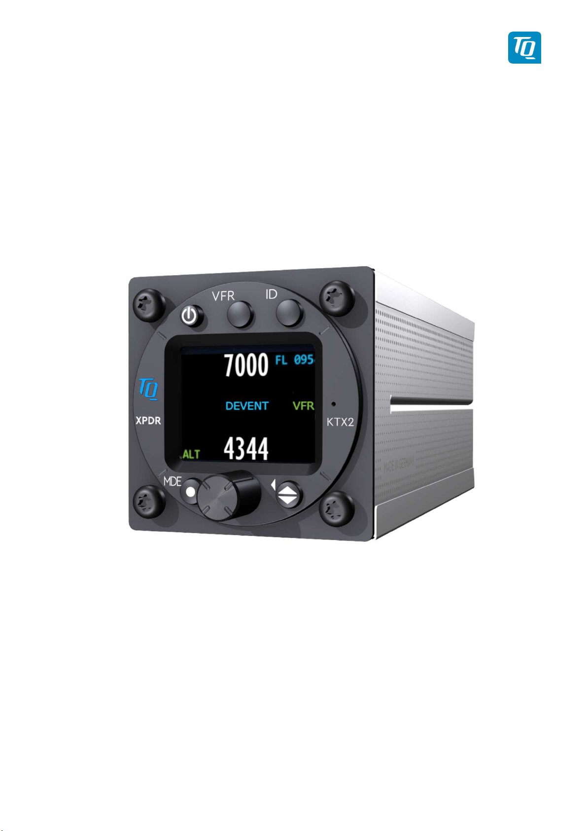
Mode-S Transponder
KTX2
Standard
KTX2-S (Standard) with ADS-B with Part-No 304110
Operation and Installation
Manual
KTX2.A-MAN.0202.en._FCC geändert.docx Page 2 of 49
© TQ-Systems GmbH. All information contained in this documents have to be treated strictly confidential. The transfer of presentations and know-how to third parties
requires the prior written consent of TQ-Systems GmbH.
TQ Aviation KTX2.0300
EASA.AP445 MAN
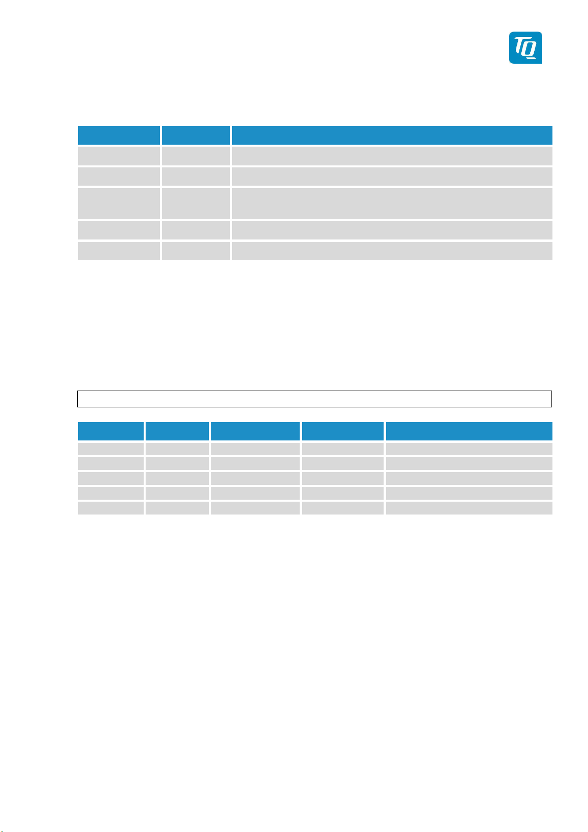
Revision List
Revision Date Topic
0100 24.03.2017 Initial Release
0101 20.02.2018 Amendments for extended Squitter and maintenance
0201 10.04.2019 Change due to new microcontroller and new functionalities ac-
0202 17.04.2019 Amendment of Software License Clearing and added Cap. 10
cording to EUROCAE ED-102A / RTCA DO-260B
Service Bulletins (SB)
Service Bulletins must be inserted in the manual and added to this table.
No SB No Rev. Release date Date Added Name
KTX2.A-MAN.0202.en._FCC geändert.docx Page 3 of 49
© TQ-Systems GmbH. All information contained in this documents have to be treated strictly confidential. The transfer of presentations and know-how to third parties
requires the prior written consent of TQ-Systems GmbH.

TQ Aviation KTX2.0300
EASA.AP445 MAN
Change History
Product
Revision
Date Description of Change
0300 09.04.2019
Base version for KTX2-S (Standard) with ADS-B
with Part-No 304110
KTX2.A-MAN.0202.en._FCC geändert.docx Page 4 of 49
© TQ-Systems GmbH. All information contained in this documents have to be treated strictly confidential. The transfer of presentations and know-how to third parties
requires the prior written consent of TQ-Systems GmbH.

TQ Aviation KTX2.0300
EASA.AP445 MAN
Table of Contents
1. General ............................................................................................................................. 7
1.1. Symbols .................................................................................................................................... 7
1.2. Abbreviations ............................................................................................................................ 8
1.3. Customer Support ..................................................................................................................... 9
1.4. Features .................................................................................................................................. 10
2. Operation ................................................................................................................................ 11
2.1. Controls and Display on the Screen ........................................................................................ 11
2.1.1. Controls ........................................................................................................................... 12
2.1.2. Indications ....................................................................................................................... 13
2.1.3. Operation menu structure ................................................................................................ 14
2.1.4. ON/OFF ........................................................................................................................... 15
2.1.5. Adjusting the Squawk ...................................................................................................... 16
2.1.6. Transponder-Modes ........................................................................................................ 17
2.1.7. VFR – Squawk ................................................................................................................ 17
2.1.8. Squawk Ident (ID, SPI) .................................................................................................... 18
2.1.9. Flight/Ground Indication ................................................................................................... 18
2.2. Adjustable parameters in operation mode ............................................................................... 19
2.2.1. Flight ID ........................................................................................................................... 19
2.2.2. Flight ID ........................................................................................................................... 19
2.2.3. GNSS Data ...................................................................................................................... 20
2.2.4. Extended Squitter ............................................................................................................ 21
3. Set-Up ..................................................................................................................................... 22
3.1. Entering Set Up ....................................................................................................................... 24
3.1.1. Display brightness ........................................................................................................... 24
3.1.2. Set Flight-IDentifier (FID) ................................................................................................. 25
3.1.2.1. Multiple Flight ID’s and Aircraft addresses ....................................................................... 26
3.1.3. Aircraft Address (AA) ....................................................................................................... 27
3.1.4. Device Parameter ............................................................................................................ 28
3.1.4.1. Aircraft Category.............................................................................................................. 29
3.1.4.2. Ground Switch ................................................................................................................. 30
3.1.4.3. Speed Category .............................................................................................................. 30
3.1.4.4. Select GNSS Device ....................................................................................................... 31
3.1.4.5. Select Length/Width ........................................................................................................ 32
3.1.4.6. GNSS Antenna Offset ..................................................................................................... 32
3.1.5. Modify VFR ...................................................................................................................... 33
3.1.6. Factory Reset .................................................................................................................. 34
3.1.7. Test Menu ....................................................................................................................... 34
3.1.7.1. Altitude offset ................................................................................................................... 35
3.1.7.2. Test Mode ....................................................................................................................... 35
3.1.7.3. Device Info ...................................................................................................................... 35
4. Errors and Warnings ............................................................................................................... 36
4.1. Setup Error .............................................................................................................................. 36
4.2. Critical Errors .......................................................................................................................... 36
4.2.1. Error FPGA ...................................................................................................................... 37
4.2.2. Internal Communication failure ........................................................................................ 37
4.2.3. Do System Restart .......................................................................................................... 37
4.3. General Failure ....................................................................................................................... 37
4.3.1. CRC Failure ..................................................................................................................... 37
4.4. Warnings ................................................................................................................................. 38
KTX2.A-MAN.0202.en._FCC geändert.docx Page 5 of 49
© TQ-Systems GmbH. All information contained in this documents have to be treated strictly confidential. The transfer of presentations and know-how to third parties
requires the prior written consent of TQ-Systems GmbH.

TQ Aviation KTX2.0300
EASA.AP445 MAN
4.4.1. Battery Warning ............................................................................................................... 38
4.4.2. Antenna Warning ............................................................................................................. 38
4.4.3. TRX Warning ................................................................................................................... 39
5. Installation ............................................................................................................................... 40
5.1. Equipment Connections .......................................................................................................... 40
5.1.1. Electrical Connections ..................................................................................................... 40
5.1.2. Mutual Suppression ......................................................................................................... 40
5.1.3. Ground Switch ................................................................................................................. 40
5.1.4. Static Air Port .................................................................................................................. 40
5.1.5. Interface .......................................................................................................................... 41
5.2. Wiring ...................................................................................................................................... 42
5.2.1. Conductor Cross Section ................................................................................................. 42
5.2.2. Wiring Scheme ................................................................................................................ 42
6. Drawings ................................................................................................................................. 43
7. Technical Data ........................................................................................................................ 44
7.1. General ................................................................................................................................... 44
7.2. Transmitter - Receiver ............................................................................................................. 45
8. FCC related issues .................................................................................................................. 46
8.1. Radiofrequency radiation exposure Information: ..................................................................... 46
8.2. Notice ...................................................................................................................................... 46
8.3. Compliance ............................................................................................................................. 46
8.4. Modifications ........................................................................................................................... 46
9. Maintenance ........................................................................................................................... 47
9.1. Periodic Maintenance .............................................................................................................. 47
9.2. Repair ..................................................................................................................................... 47
9.3. Cleaning .................................................................................................................................. 47
10. Software License Conformity ................................................................................................... 48
List of Figures
Figure 1: Display Diagram .................................................................................................................. 11
Figure 2: Controls .............................................................................................................................. 12
Figure 3: Indicators ............................................................................................................................ 13
Figure 4: Operational menu structure ................................................................................................. 14
Figure 5: Extended Squitter ............................................................................................................... 21
Figure 6: Button functions in setup-mode ........................................................................................... 22
Figure 7: Setup menu structure .......................................................................................................... 23
Figure 8: Wiring ................................................................................................................................. 42
Figure 9: Dimensions of KTX2-S Standard round format.................................................................... 43
Figure 10: Technical Data .................................................................................................................. 44
Figure 11: Transmitter receiver .......................................................................................................... 45
KTX2.A-MAN.0202.en._FCC geändert.docx Page 6 of 49
© TQ-Systems GmbH. All information contained in this documents have to be treated strictly confidential. The transfer of presentations and know-how to third parties
requires the prior written consent of TQ-Systems GmbH.
TQ Aviation KTX2.0300
EASA.AP445 MAN
1.
General
This manual contains information about the physical, mechanical and electrical characteristics,
installation and operation of the Mode S Transponder KTX2.
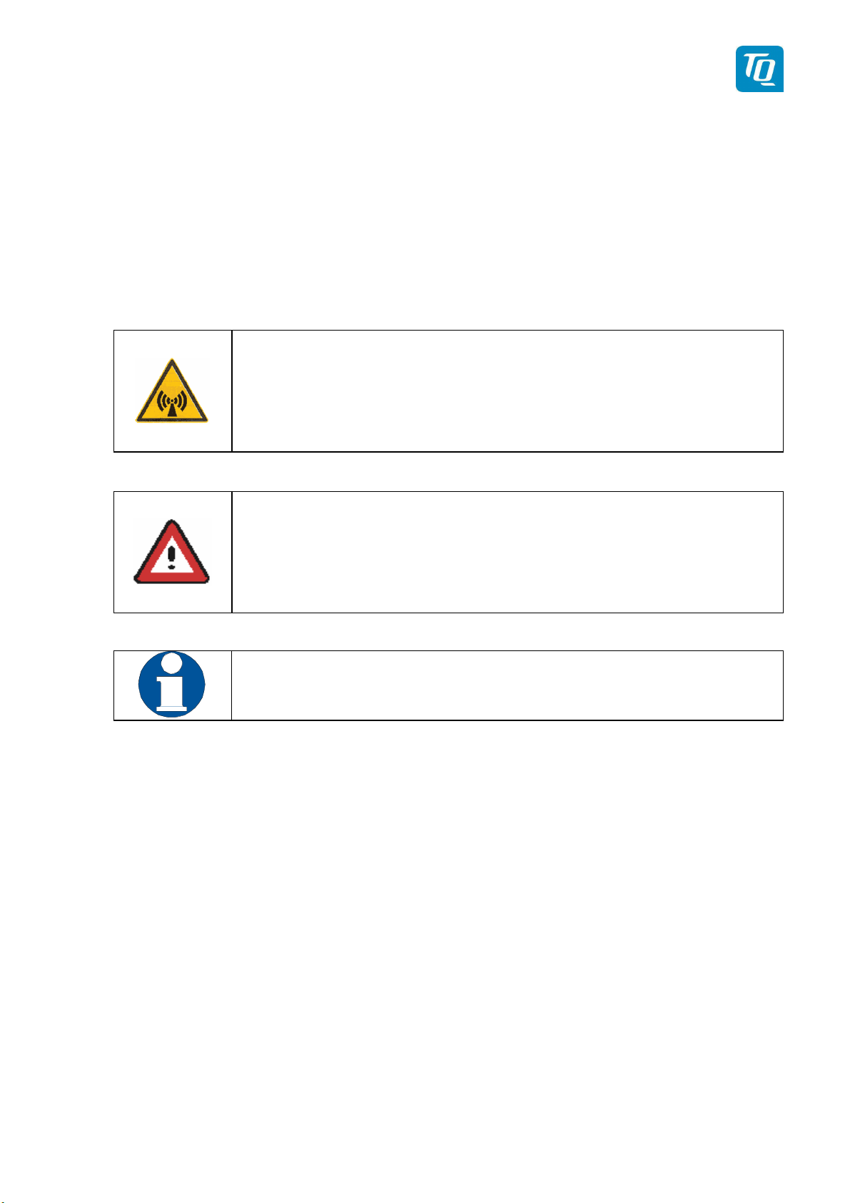
1.1.
Symbols
DANGER:
Advices whose non-observance can cause radiation damage to the human body or ignition of combustible materials.
ATTENTION:
Advices whose non-observance can cause damage to the
device or other parts of the equipment. or reduce the correct
functionality of the device.
INFORMATION
KTX2.A-MAN.0202.en._FCC geändert.docx Page 7 of 49
© TQ-Systems GmbH. All information contained in this documents have to be treated strictly confidential. The transfer of presentations and know-how to third parties
requires the prior written consent of TQ-Systems GmbH.

Abb.
Meaning
Explanation
assigned Regis-
TQ Aviation KTX2.0300
EASA.AP445 MAN
1.2.
Abbreviations
FID Flight ID
Flightplan Number or if not
tration Number of aircraft
Activation on request by controllers
SPI
Special Position Identification (ID)
„Squawk Ident“, transmits SPI Pulse for 18
seconds, which highlights the respective
traffic item on the controllers radar screen
AA Aircraft Address Assigned ICAO 24 bit address
AC Aircraft Category Defines aircraft type into specific catego-
ries
RI Reply Information Classified air speed
ADS-B Automatic Dependent Sur-
-
veillance Broadcast
KTX2.A-MAN.0202.en._FCC geändert.docx Page 8 of 49
© TQ-Systems GmbH. All information contained in this documents have to be treated strictly confidential. The transfer of presentations and know-how to third parties
requires the prior written consent of TQ-Systems GmbH.

TQ Aviation KTX2.0300
EASA.AP445 MAN
1.3.
Customer Support
In order to facilitate a rapid handling of returned shipments, please send your request at
the email address below. Additional information and FAX number can be found on the
TQ Avionics web portal:
www.tq-avionics.com
Any suggestions for improvement manuals are
welcome. Contact:
info@tq-avionics.com
Information on software updates are available at TQ.
www.tq-avionics.com
KTX2.A-MAN.0202.en._FCC geändert.docx Page 9 of 49
© TQ-Systems GmbH. All information contained in this documents have to be treated strictly confidential. The transfer of presentations and know-how to third parties
requires the prior written consent of TQ-Systems GmbH.

TQ Aviation KTX2.0300
EASA.AP445 MAN
1.4.
Features
In order to operate the Mode-S transponder it is necessary to request (in time) an ICAO 24-Bit Aircraft Address at the responsible
National Aviation Authorities. The received code must be configured within the transponder (see chapter. 3.1.2 “Flight-ID (FID) &
Set-Up”).
• Class 1 Level 2els Non-Diversity Mode-S-Transponder for ground based interrogations at 1030 MHz and response at 1090 MHz
• Replies to Secondary Radar Interrogations
o Mode-A replies with a Squawk (one of 4096 possible Codes; e.g. flight
plan number, Squawk assigned by a Controller or the VFR Squawk).
o Mode C replies, including Encoded Flight Level.
o Mode S replies, including Aircraft Address and Flight Level.
o Event Squitter, containing Identification Information.
o Extended Squitter, including position data.
• IDENT capability for activating the Special Position Identification“- Pulse (SPI)
for 18 seconds, which is requested by the Controller „Squawk Ident“
• Maximum flight level 30 000ft; maximum airspeed 250kt
• Display information contains Squawk code, mode of operation and pressure alti-
tude.
•
Temperature compensated
high
precision
piezo-resistive pressure sensor
• RS-232 data port enabling connection with mutual suppression and On the
Ground (weight on wheels) inputs. In addition, an appropriate GPS receiver for
“extended squitter” can be connected.
• 8 storable entries for AA-/AC-Code, FID,
•
Ground-Switch support, RI-Code.
KTX2.A-MAN.0202.en._FCC geändert.docx Page 10 of 49
© TQ-Systems GmbH. All information contained in this documents have to be treated strictly confidential. The transfer of presentations and know-how to third parties
requires the prior written consent of TQ-Systems GmbH.
TQ Aviation KTX2.0300
EASA.AP445 MAN
2.
Operation
2.1.
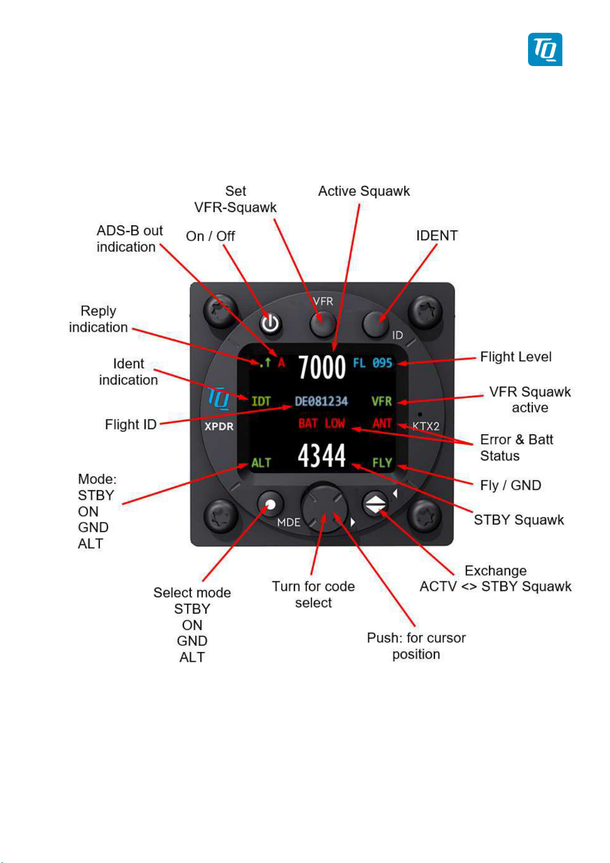
Controls
and Display on the Screen
Figure 1: Display Diagram
KTX2.A-MAN.0202.en._FCC geändert.docx Page 11 of 49
© TQ-Systems GmbH. All information contained in this documents have to be treated strictly confidential. The transfer of presentations and know-how to third parties
requires the prior written consent of TQ-Systems GmbH.
TQ Aviation KTX2.0300
EASA.AP445 MAN
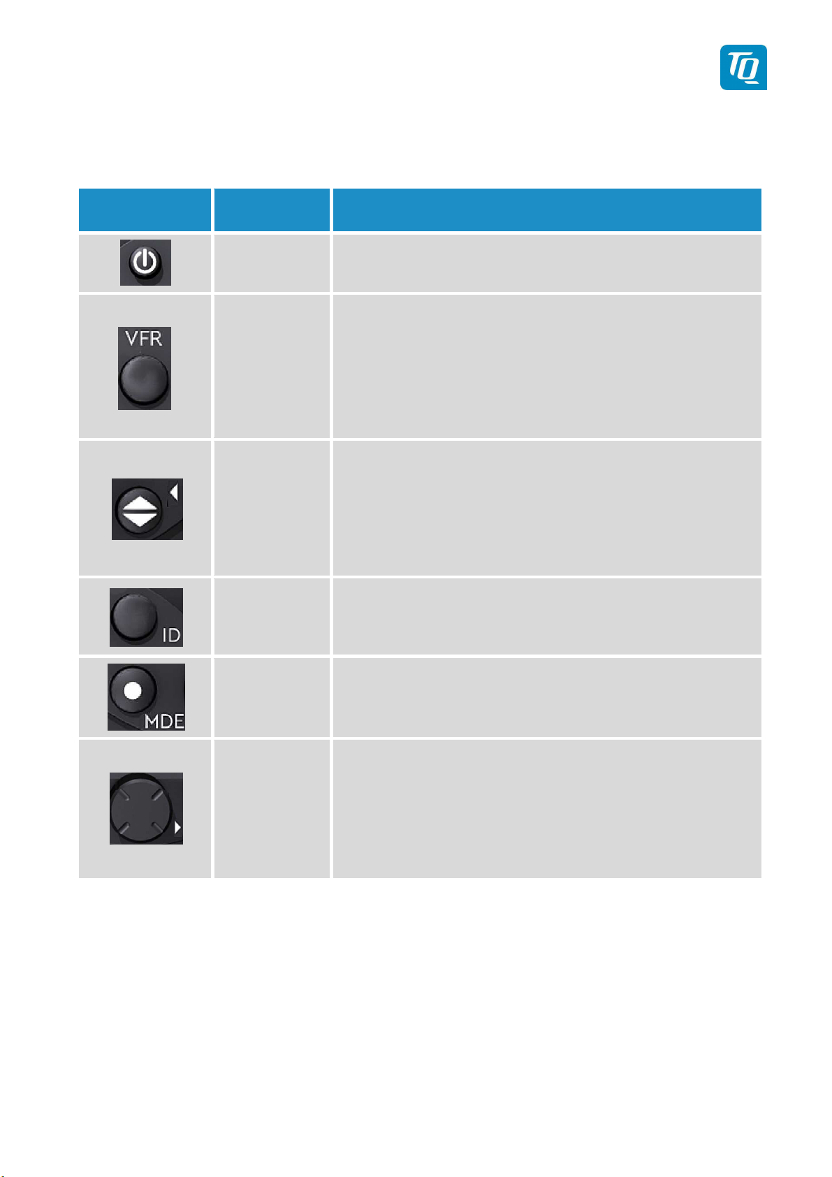
2.1.1.
Controls
Key Designation Function
ON/OFF
Push = ON. This switch is mechanically locked until it
is pushed a second time.
Activate/deactivate VFR Squawk
(press shortly)
VFR
Store the standby Squawk as VFR/VFRWSquawk (press button 3 s) see chapter “2.6 VFR –
Squawk”.
1.
CHANGE
Exchange of the active and standby-Squawk
2.
Works as cursor back button when entering values
and also for navigating backwards through the configuration menu.
IDENT
„Squawk Ident“, sends Ident marking (SPI) for 18s (in
normal mode) see chapter. “2.9 Flight- ID (FID) &
Set-Up”
MODE
Rotary knob
Figure 2: Controls
Select Transponder-Mode ACS, A-S or
Standby (see chapter “2.4 TransponderModes”)
1. Enter values at current cursor position, select options; set standby Squawk
2. Works as cursor forward button when entering
values and also for navigating forward through
the configuration menu.
KTX2.A-MAN.0202.en._FCC geändert.docx Page 12 of 49
© TQ-Systems GmbH. All information contained in this documents have to be treated strictly confidential. The transfer of presentations and know-how to third parties
requires the prior written consent of TQ-Systems GmbH.
TQ Aviation KTX2.0300
EASA.AP445 MAN
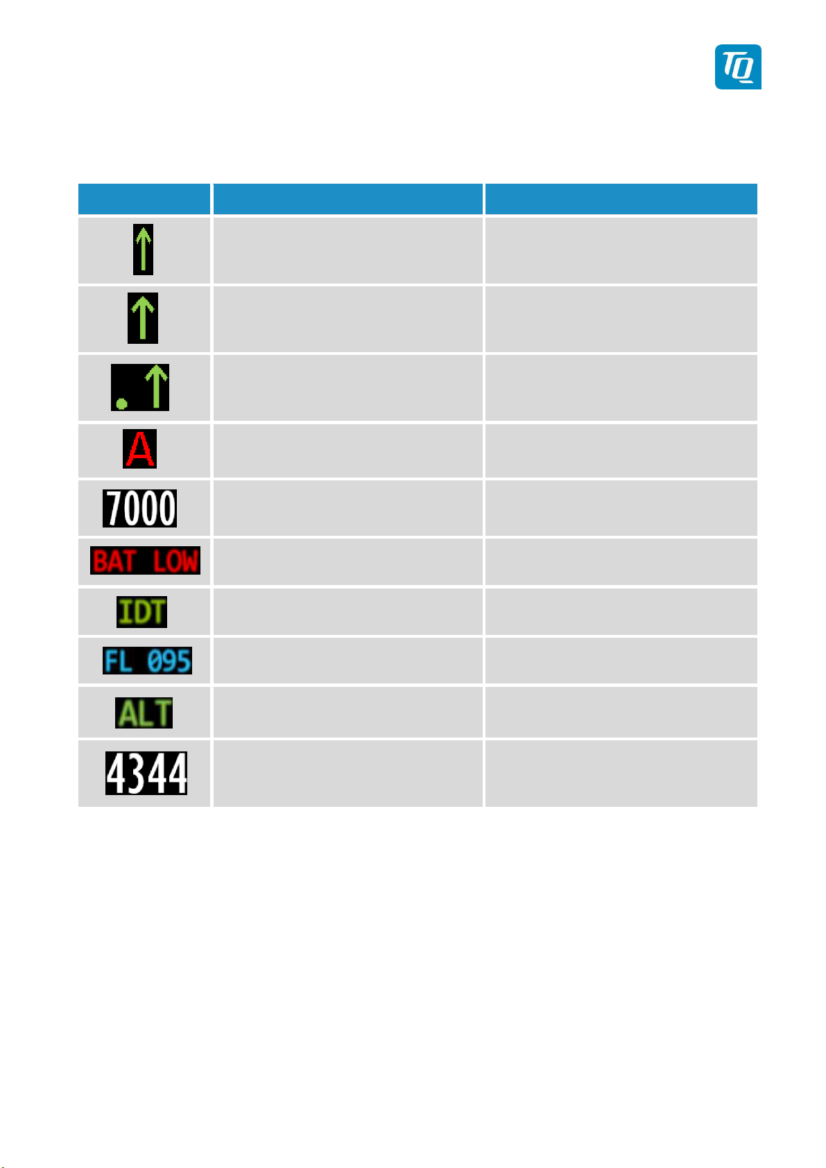
2.1.2.
Indications
Indication Meaning Remark
Transponder is transmitting
Mode-A/C Replies on Inter-
Appears per reply
rogations
Transponder is transmitting
Mode-S Replies on Inter-
Appears per reply
rogations
Transponder is locked by
a ground station and will
Appears at every addressed reply
be directly addressed
Extended Squitter
Active Squawk
Battery power too low Blinking
Transmits IDENT- Marking
Status of Extended Squitter transmission
ID („Squawk Ident“) has been
pressed – active for 18s
Flight Level Flight Level (in 100ft steps)
Mode display
(STBY, ON, GND, ALT)
Figure 3: Indicators
Standby-Squawk
see chapter. 2.1.6 TransponderModes
Can be changed with active
Squawk by pushing the UP/DOWN
(toggle) button
KTX2.A-MAN.0202.en._FCC geändert.docx Page 13 of 49
© TQ-Systems GmbH. All information contained in this documents have to be treated strictly confidential. The transfer of presentations and know-how to third parties
requires the prior written consent of TQ-Systems GmbH.
TQ Aviation KTX2.0300
EASA.AP445 MAN
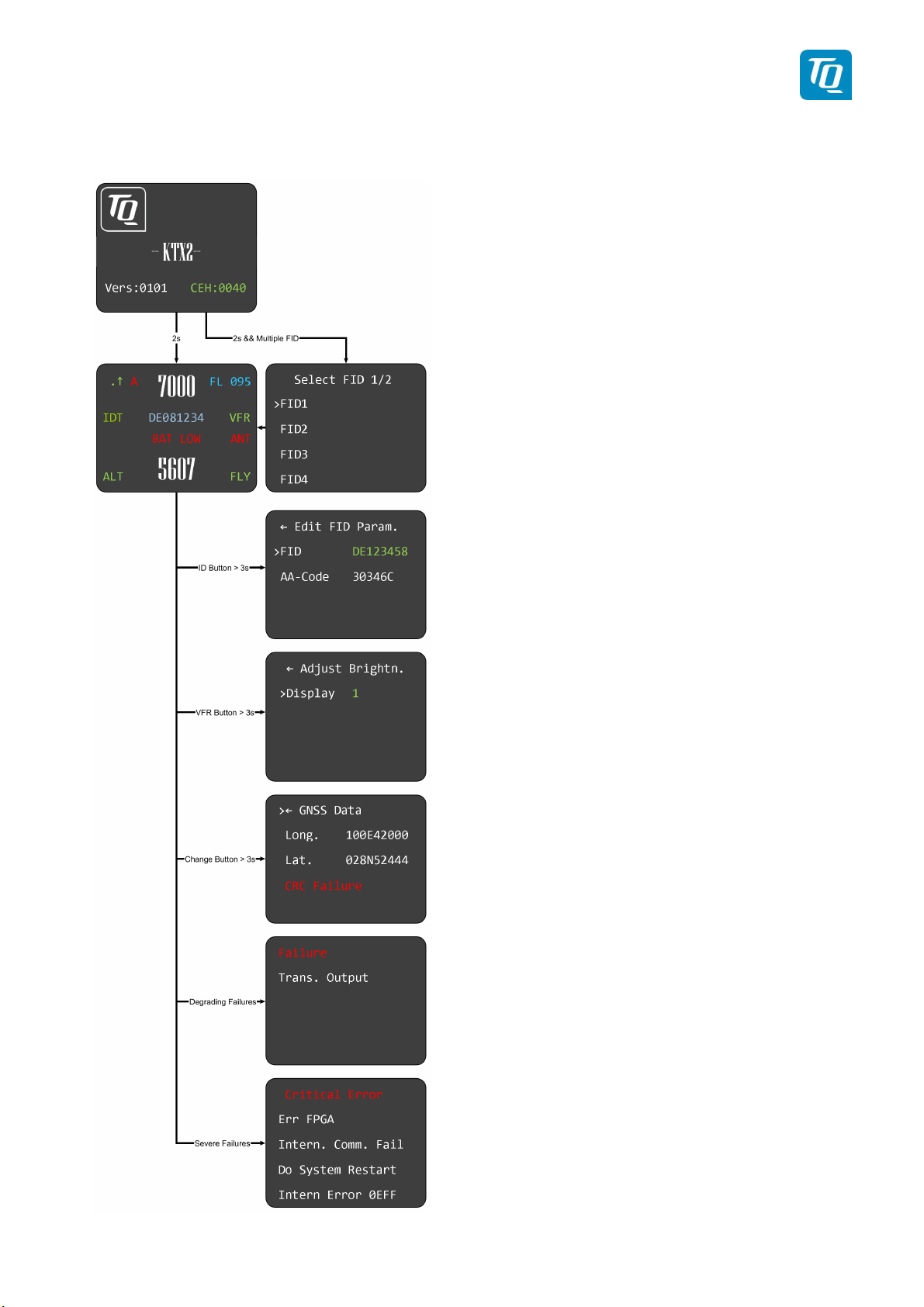
2.1.3.
Operation
menu structure
Figure 4: Operational menu structure
KTX2.A-MAN.0202.en._FCC geändert.docx Page 14 of 49
© TQ-Systems GmbH. All information contained in this documents have to be treated strictly confidential. The transfer of presentations and know-how to third parties
requires the prior written consent of TQ-Systems GmbH.

TQ Aviation KTX2.0300
EASA.AP445 MAN
2.1.4. ON/OFF
The device is switched on/off by pushing the mechanically locked key. After power
up, the display appears as follows (example):
Device Name
-- KTX2 --
Software-Version
e.g. V.0101
Firmware-Version
e.g. FPGA: 6.0
After approx. 2 seconds the normal operation window appears and the transponder will enter the mode ALT. If a weight on wheels switch is installed and the aircraft
is on ground the mode GND will be set.
No GND switch installed GND-switch installed, on GND
KTX2.A-MAN.0202.en._FCC geändert.docx Page 15 of 49
© TQ-Systems GmbH. All information contained in this documents have to be treated strictly confidential. The transfer of presentations and know-how to third parties
requires the prior written consent of TQ-Systems GmbH.
TQ Aviation KTX2.0300
EASA.AP445 MAN
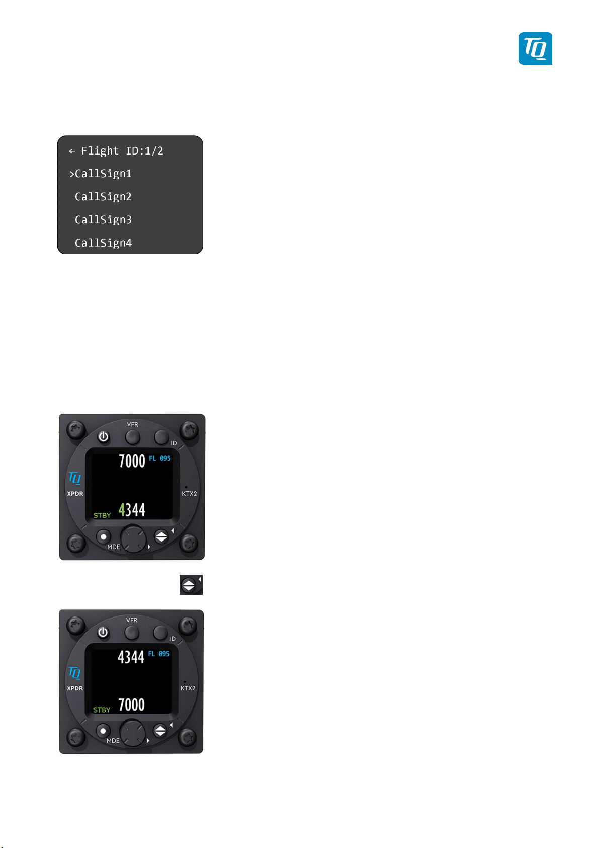
In case that multiple Flight ID’s are present, the screen will first display the selection menu for
one of the Flight ID’s:
Select the correct Flight ID by rotating the rotary knob to the one you chose and confirm by
pushing. The screen will switch automatically to the normal operation window.
2.1.5. Adjusting the Squawk
When pushing the rotating knob in the normal operating mode, the first number of the standby squawk turns green, and can be adjusted by rotating the rotary knob. Pushing the rotary
knob will save the selected number and jump to the next digit which also will turn green during adjustment.
Continue with the remaining numbers in this way until the desired squawk is set.
With the toggle button you can turn the stand-by squawk into the active squawk.
The active squawk is always on the top line.
KTX2.A-MAN.0202.en._FCC geändert.docx Page 16 of 49
© TQ-Systems GmbH. All information contained in this documents have to be treated strictly confidential. The transfer of presentations and know-how to third parties
requires the prior written consent of TQ-Systems GmbH.

TQ Aviation KTX2.0300
EASA.AP445 MAN
2.1.6. Transponder-
Modes
The active mode is displayed at the bottom left corner.
STBY Transponder is
on
but
does not
respond to any interrogation.
GND Transponder responds to Mode-S interrogations.
ON Transponder responds to all interrogations, only altitude is not transmit-
ted.
ALT Transponder responds to all interrogations.
During the flight the Mode ALT should always be set, unless the air traffic control gives other
instructions.
While rolling on the ground the transponder should be set to GND, unless the installation includes a weight on wheels switch. In this case, the mode changes automatically.
The Mode-selection is done by (repeatedly) pushing the MDE button.
To enable or disable the Extended Squitter, press the MDE button for more than 3 seconds.
2.1.7. VFR –
The factory setting of the VFR transponder code is 7000. The VFR transponder code however can be defined in accordance with local requirements, see setup menu chapter 3.1.5.
To activate the VFR-Squawk push the VFR button. VFR is then indicated on the display as
the active squawk.
Squawk
KTX2.A-MAN.0202.en._FCC geändert.docx Page 17 of 49
© TQ-Systems GmbH. All information contained in this documents have to be treated strictly confidential. The transfer of presentations and know-how to third parties
requires the prior written consent of TQ-Systems GmbH.
TQ Aviation KTX2.0300
EASA.AP445 MAN
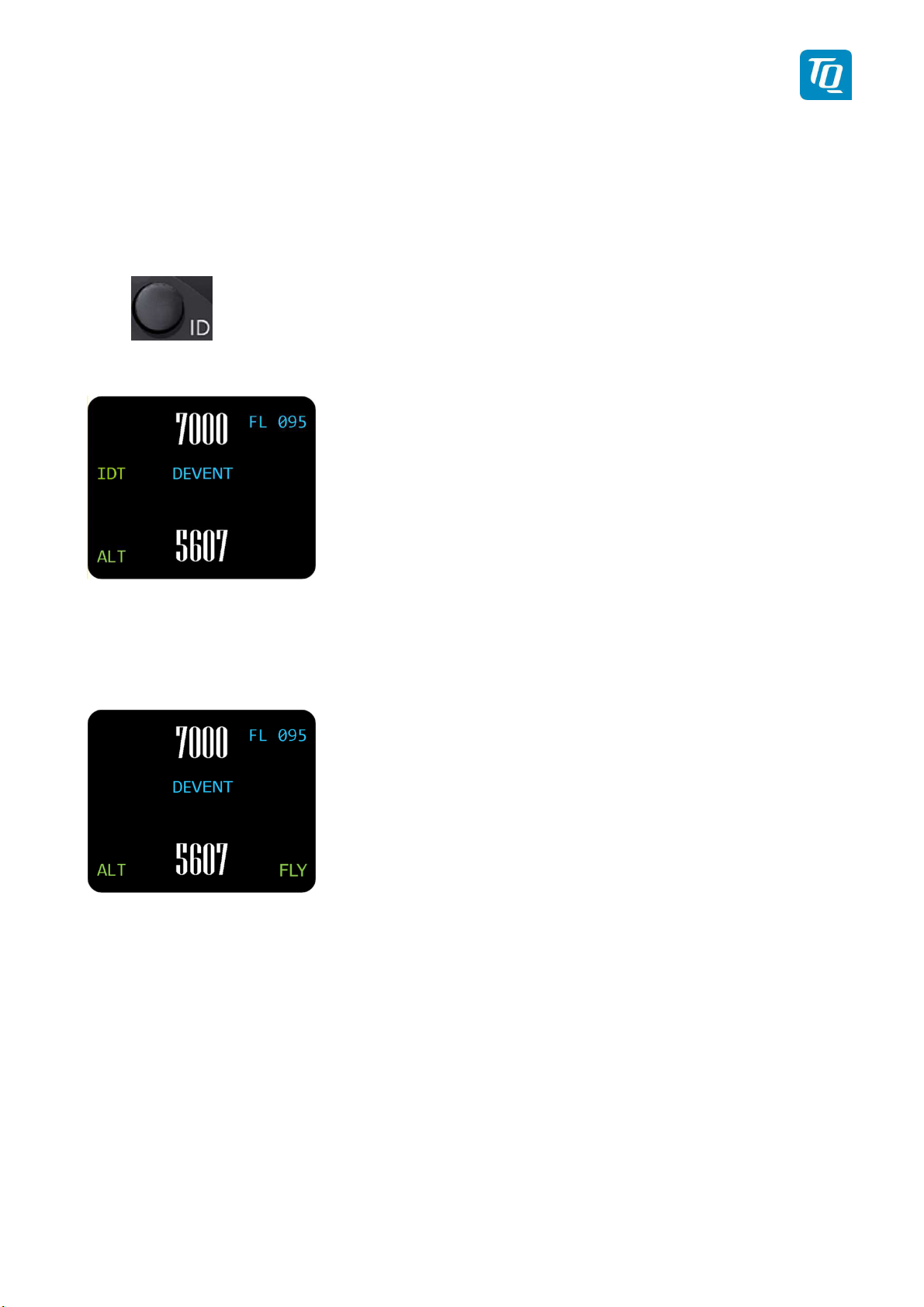
2.1.8.
On request of the air traffic control, push the ID button (when not in the STBY mode).
Transmission of the ID signal will last for 18 seconds and “IDT” is displayed above the
mode and left side of the Flight ID.
Squawk Ident
(ID, SPI)
2.1.9.
Aircrafts with AIR/GROUND switches display “FLY” (Flight) or “GND” (Ground) in the
lower right corner.
This function must be activated in the set-up procedure (see chap. 3.1.4.2).
When this function is not activated, there are no indications on the display and modes
must be manually selected in accordance with chapter 2.1.6.
Flight/Ground
Indication
KTX2.A-MAN.0202.en._FCC geändert.docx Page 18 of 49
© TQ-Systems GmbH. All information contained in this documents have to be treated strictly confidential. The transfer of presentations and know-how to third parties
requires the prior written consent of TQ-Systems GmbH.

TQ Aviation KTX2.0300
EASA.AP445 MAN
2.2.
Adjustable
parameters in operation mode
2.2.1.
Flight
ID
To modify the Flight ID during operation, push the ID button for at least 3 seconds.
The parameters can be adjusted in the same way like described in chapter 3.1.2.
2.2.2. Flight ID
To modify the display brightness during operation, push the VFR button for at least 3 seconds.
The menu appears, brightness can be adjusted by turning and pushing the rotary knob in the
same way as described in setup menu (see chap. 2.1.1).
KTX2.A-MAN.0202.en._FCC geändert.docx Page 19 of 49
© TQ-Systems GmbH. All information contained in this documents have to be treated strictly confidential. The transfer of presentations and know-how to third parties
requires the prior written consent of TQ-Systems GmbH.

TQ Aviation KTX2.0300
EASA.AP445 MAN
2.2.3. GNSS Data
The actual GNSS data can be displayed when pushing the toggle button for at least 3 seconds:
KTX2.A-MAN.0202.en._FCC geändert.docx Page 20 of 49
© TQ-Systems GmbH. All information contained in this documents have to be treated strictly confidential. The transfer of presentations and know-how to third parties
requires the prior written consent of TQ-Systems GmbH.

TQ Aviation KTX2.0300
EASA.AP445 MAN
2.2.4.
Extended Squitter
The Symbols for Extended Squitter show the current operational status of ES transmission:
Indication Function Description
Extended Squitter on.
Letter “A” appears white
Extended Squitter on.
Letter “A” appears yellow
Extended Squitter on
Letter “A” appears red
ADS-B out function is active and
transmitting messages
ADS-B out function is active but not
transmitting messages
ADS-B out function is active and
transmitting type ZERO position messages or no position messages due to
missing position data (longitude, altitude, latitude)
Extended Squitter off
Letter “A” disappears
No transmitting data
Figure 5: Extended Squitter
KTX2.A-MAN.0202.en._FCC geändert.docx Page 21 of 49
© TQ-Systems GmbH. All information contained in this documents have to be treated strictly confidential. The transfer of presentations and know-how to third parties
requires the prior written consent of TQ-Systems GmbH.

TQ Aviation KTX2.0300
EASA.AP445 MAN
3. Set-Up
Figure 6: Button functions in setup-mode
KTX2.A-MAN.0202.en._FCC geändert.docx Page 22 of 49
© TQ-Systems GmbH. All information contained in this documents have to be treated strictly confidential. The transfer of presentations and know-how to third parties
requires the prior written consent of TQ-Systems GmbH.

TQ Aviation KTX2.0300
EASA.AP445 MAN
Figure 7: Setup menu structure
KTX2.A-MAN.0202.en._FCC geändert.docx Page 23 of 49
© TQ-Systems GmbH. All information contained in this documents have to be treated strictly confidential. The transfer of presentations and know-how to third parties
requires the prior written consent of TQ-Systems GmbH.

TQ Aviation KTX2.0300
EASA.AP445 MAN
3.1.
Entering Set Up
To enter setup mode, press ID button during system startup.
The following menu appears:
Rotation of the rotary knob moves to the desired menu item.
Pushing the rotary knob selects the desired parameter to be modified.
3.1.1. Display brightness
Push the rotary knob to enter brightness sub menu.
Turning the rotary knob changes the value for brightness between 1 (lowest) to 5 (highest).
When selection is done, turn rotary knob to move cursor to “Adjust Brightness.” and leave
menu by pushing the rotary knob.
KTX2.A-MAN.0202.en._FCC geändert.docx Page 24 of 49
© TQ-Systems GmbH. All information contained in this documents have to be treated strictly confidential. The transfer of presentations and know-how to third parties
requires the prior written consent of TQ-Systems GmbH.

TQ Aviation KTX2.0300
EASA.AP445 MAN
3.1.2. Set Flight-IDentifier (FID)
Rotate the rotary knob to select Flight ID.
Push the rotary knob to enter Flight ID sub menu.
Select “Add” to add a Flight ID, modify to modify or delete to delete a Flight ID by pushing the
rotary knob.
In the “Add” sub menu the following screen appears:
Press and rotate the rotary knob to enter the Flight ID. Press to jump to the next digit, rotate
to select the desired character until the Flight ID is complete.
When selection is done, turn rotary knob to move cursor to “Save”, save configuration by
pushing the rotary knob. Leave the menu entering the first line (“Edit FID Parameter”) and by
pushing the rotary knob.
KTX2.A-MAN.0202.en._FCC geändert.docx Page 25 of 49
© TQ-Systems GmbH. All information contained in this documents have to be treated strictly confidential. The transfer of presentations and know-how to third parties
requires the prior written consent of TQ-Systems GmbH.
TQ Aviation KTX2.0300
EASA.AP445 MAN
ICAO regulations require Mode-S data to contain a valid flight identification (FID), to ensure
automatic exchange of flight plan and radar data. Commercial flights usually have their own
FIDs. General aviation FIDs should be the registration letters or numbers of the aircraft. The
FID must not be confused with the 24-bit Aircraft Address. The FID is left aligned and shown
in green characters. The FID may not contain blanks however the non-used most right characters must be blank. The FID must start with the nationality code.
Enter FID left-aligned, without any blanks or dashes (!), e.g.
DENWS for the marking D-ENWS. The last remaining digits
shall be filled with blanks.
FID containing blanks characters are invalid.
Missing FID disables mode-S operation and A/C-mode only
will be engaged.
See chapter “4 Self-Test, Errors and Warnings”
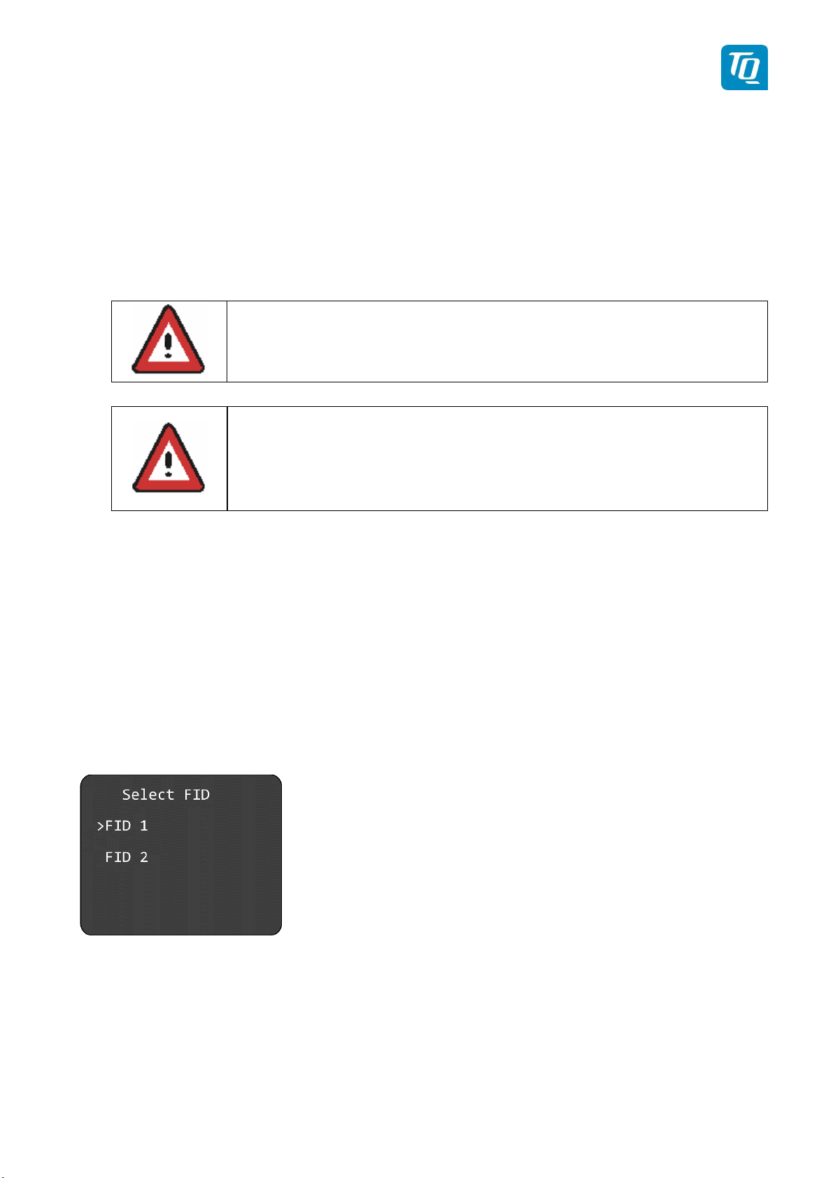
3.1.2.1. Multiple Flight ID’s and Aircraft addresses
In case, the KTX2 transponder is used for multiple aircraft (e.g. in a portable station as used
in hot-air/gas filled balloons), up to eight FID’s can be stored in the KTX2 memory.
To every Flight ID, of course the appropriate Aircraft Address must be assigned in the same
way than for the use of one FID only.
In case multiple FID’s are stored in the memory, the KTX2 will prompt you to select one of
the stored FIDs each time it is turned on, before it goes into normal operating mode:
Further Flight ID’s are to be stored in the same way, like under chapter 3.1.2
If all eight possible ID’s have been stored, the following message appears:
KTX2.A-MAN.0202.en._FCC geändert.docx Page 26 of 49
© TQ-Systems GmbH. All information contained in this documents have to be treated strictly confidential. The transfer of presentations and know-how to third parties
requires the prior written consent of TQ-Systems GmbH.

TQ Aviation KTX2.0300
EASA.AP445 MAN
3.1.3. Aircraft Address (AA)
Note:
Before you can enter the Aircraft Address, the Flight ID needs to be defined.
Rotate the rotary knob to select Flight ID.
Push the rotary knob to enter Flight ID sub menu
.
Select “Add” by pushing the rotary knob.
KTX2.A-MAN.0202.en._FCC geändert.docx Page 27 of 49
© TQ-Systems GmbH. All information contained in this documents have to be treated strictly confidential. The transfer of presentations and know-how to third parties
requires the prior written consent of TQ-Systems GmbH.

TQ Aviation KTX2.0300
EASA.AP445 MAN
In the “Add” sub menu the following screen appears:
Rotate the rotary knob to enter the AA-Code submenu. Press to jump to the next digit, rotate
to select the desired character until the Aircraft Address is complete.
When code is complete, turn rotary knob to move cursor to “Save”, save configuration by
pushing the rotary knob. Leave the menu entering the first line (“Edit FID Param.”) and by
pushing the rotary knob.
3.1.4. Device Parameter
The submenu "Device Parameter" can also be accessed via the submenu "Flight ID":
Rotate the rotary knob to select Flight ID.
Push the rotary knob to enter Flight ID sub menu.
Select “Add” by pushing the rotary knob.
KTX2.A-MAN.0202.en._FCC geändert.docx Page 28 of 49
© TQ-Systems GmbH. All information contained in this documents have to be treated strictly confidential. The transfer of presentations and know-how to third parties
requires the prior written consent of TQ-Systems GmbH.

TQ Aviation KTX2.0300
EASA.AP445 MAN
In the “Add” sub menu the following screen appears:
Rotate the rotary knob and push to enter the Device Parameter Submenu.
The following screen appears:
Page 1 Page 2
3.1.4.1. Aircraft Category
Push the rotary knob to enter the “Aircraft Category submenu. The following screen appears:
Page 1 Page 2
Make the selection which fits to the category of your aircraft by rotating to the appropriate
category. Confirm by pushing the rotary knob. Leave the menu in the usual way.
KTX2.A-MAN.0202.en._FCC geändert.docx Page 29 of 49
© TQ-Systems GmbH. All information contained in this documents have to be treated strictly confidential. The transfer of presentations and know-how to third parties
requires the prior written consent of TQ-Systems GmbH.

TQ Aviation KTX2.0300
EASA.AP445 MAN
Note:
The KTX2 is not yet certified for A/C FixW>5.7t, speed >250kts and helicopters (RotorCr).
Therefore, these items are not yet selectable.
3.1.4.2. Ground Switch
The next submenu is activates / deactivates AIR/GND switch function. YES/NO can be selected by rotating the rotary knob, push to confirm.
3.1.4.3. Speed Category
In the next submenu you should select the typical cruising speed range of your aircraft.
Select the appropriate value for your aircraft by rotating the rotary knob and push to confirm.
Leave the menu by moving the cursor to the upper line by rotating the rotary knob and push.
KTX2.A-MAN.0202.en._FCC geändert.docx Page 30 of 49
© TQ-Systems GmbH. All information contained in this documents have to be treated strictly confidential. The transfer of presentations and know-how to third parties
requires the prior written consent of TQ-Systems GmbH.

TQ Aviation KTX2.0300
EASA.AP445 MAN
3.1.4.4. Select GNSS Device
In case the KTX2’s extended squitter function is used, an appropriate WAAS GPS source
needs to be connected (see chapter 5 wiring).
Note:
In countries and airspace, where ADS-B (out) function is mandatory (e.g. USA) full compliance with those regulations (e.g. FAA 2020 mandate) is granted with the KTX2 in connection
with the NexNav Mini WAAS GPS receiver. This normally is the right choice for TC’d aircraft.
Other aircraft voluntarily equipped with ADS-B like experimentals, gliders, ultralights etc. may
be equipped with an appropriate low-cost WAAS GPS source. It is encouraged to use only
GPS receivers recommended by TQ.
After jump to the “Select GNSS Device”, the following screen appears
:
• If no WAAS GPS is connected, select “No GNSS Device”.
• If a NexNav mini is connected, select “NexNav mini”
• “Approved Device” shall be selected, if a recommended WAAS GPS source capable
of the GPRMC-sentence (as defined in the NMEA 0183 protocol) which contains the
position information as well as velocity, track, date and time is used.
In the “Approved device” menu, there is another submenu, where the appropriate Baud Rate
for the GNSS device can be selected:
KTX2.A-MAN.0202.en._FCC geändert.docx Page 31 of 49
© TQ-Systems GmbH. All information contained in this documents have to be treated strictly confidential. The transfer of presentations and know-how to third parties
requires the prior written consent of TQ-Systems GmbH.

TQ Aviation KTX2.0300
EASA.AP445 MAN
When settings have been done, leave the menu by moving the cursor to the upper line by
rotating the rotary knob and push.
3.1.4.5. Select Length/Width
After entering the “length/Width” menu, the following screen appears.
The values to be entered are in meters (rounded) for example:
Aircraft length is 7,5m, the entry shall be 08.
Aircraft width (wingspan) is 9,4m, the entry shall be 09.4
When the correct value has been entered, leave the menu by moving the cursor to the upper
line by rotating the rotary knob and push.
3.1.4.6. GNSS Antenna Offset
Within the antenna offset menu, the longitudinal and lateral position of the GPS Antenna is to
be entered. While mainly important for large aircraft, the values can be entered for small aircraft as well.
KTX2.A-MAN.0202.en._FCC geändert.docx Page 32 of 49
© TQ-Systems GmbH. All information contained in this documents have to be treated strictly confidential. The transfer of presentations and know-how to third parties
requires the prior written consent of TQ-Systems GmbH.

TQ Aviation KTX2.0300
EASA.AP445 MAN
• Longitudinal offset: Enter the distance in meters of the GPS antenna from the NOSE
of the aircraft.
• Lateral offset: Enter the lateral distance of the GPS antenna from the longitudinal
(Roll) axis of the aircraft. For most small aircraft “00” is correct. In case an antenna
offset is applicable, the position to the left side of the aircraft will require a negative
sign, to the right a positive sign.
When the correct value has been entered, leave the menu by moving the cursor to the upper
line by rotating the rotary knob and push.
3.1.5. Modify VFR
In setup mode, move to “Modify VFR” by rotating the rotary knob and push to enter the
submenu.
The following menu appears:
Pushing and rotating the rotary knob selects and modifies the digits.
Note:
Make sure, that you enter the correct VFR Squawk for the particular country where your aircraft is operated.
Examples:
Germany: VFR Squawk = 7000
USA: VFR Squawk = 1200
KTX2.A-MAN.0202.en._FCC geändert.docx Page 33 of 49
© TQ-Systems GmbH. All information contained in this documents have to be treated strictly confidential. The transfer of presentations and know-how to third parties
requires the prior written consent of TQ-Systems GmbH.

TQ Aviation KTX2.0300
EASA.AP445 MAN
3.1.6. Factory Reset
In certain cases it may be necessary to perform a factory reset.
If you select “Yes” and confirm by pushing the rotary knob, the system will do a factory reset.
You will be prompted to restart the transponder.
3.1.7. Test Menu
The Test Menu incorporates the following submenus:
KTX2.A-MAN.0202.en._FCC geändert.docx Page 34 of 49
© TQ-Systems GmbH. All information contained in this documents have to be treated strictly confidential. The transfer of presentations and know-how to third parties
requires the prior written consent of TQ-Systems GmbH.

TQ Aviation KTX2.0300
EASA.AP445 MAN
3.1.7.1. Altitude offset
3.1.7.2. Test Mode
The Test Mode displays three parameters:
• Operating voltage (Battery)
• DC Converter voltage
• Altitude (in feet)
3.1.7.3. Device Info
The submenu “Device Info” displays the checksum of the software / firmware and the serial
number of the device.
KTX2.A-MAN.0202.en._FCC geändert.docx Page 35 of 49
© TQ-Systems GmbH. All information contained in this documents have to be treated strictly confidential. The transfer of presentations and know-how to third parties
requires the prior written consent of TQ-Systems GmbH.

TQ Aviation KTX2.0300
EASA.AP445 MAN
4. Errors and Warnings
The KTX2 distinguishes 3 types of anomalies:
•
Warnings
•
Setup Errors
•
Elementary Function Errors
4.1. Setup Error
If no FID-Code (Flight ID) and the corresponding Aircraft Address (AA-Code) is entered or
uncomplete, the following displays will appear after switching on the transponder:
Enter appropriate FID and AA-Code in accordance with chapters 3.1.2 and 3.1.3.
Note:
As long no FID / AA is set, the transponder will operate in A/C mode only.
4.2. Critical Errors
In case a critical error is present, the following messages can appear:
KTX2.A-MAN.0202.en._FCC geändert.docx Page 36 of 49
© TQ-Systems GmbH. All information contained in this documents have to be treated strictly confidential. The transfer of presentations and know-how to third parties
requires the prior written consent of TQ-Systems GmbH.

TQ Aviation KTX2.0300
EASA.AP445 MAN
4.2.1. Error FPGA
Severe failure. No access to FPGA. Send Unit for servicing.
4.2.2. Internal Communication failure
Severe failure. Send Unit for servicing.
4.2.3. Do System Restart
Switch device off and on again
4.3. General Failure
No output of transponder. Severe failure. Check environment. If no root cause can be discovered, send unit for servicing.
4.3.1. CRC Failure
KTX2.A-MAN.0202.en._FCC geändert.docx Page 37 of 49
© TQ-Systems GmbH. All information contained in this documents have to be treated strictly confidential. The transfer of presentations and know-how to third parties
requires the prior written consent of TQ-Systems GmbH.

TQ Aviation KTX2.0300
EASA.AP445 MAN
Data from GPS source not sufficient (no or not enough satellites)
4.4. Warnings
4.4.1. Battery Warning
In case the on board voltage falls below 11VDC, the following warning appears:
Take appropriate measures before the unit fails due to low voltage. The KTX2 is designed to
operate above 9 VDC. Do not operate the unit below 9 volts.
4.4.2. Antenna Warning
In case of bad antenna adaption or antenna failure, the following message appears:
Check your antenna installation (cable, connectors etc.) to resolve the problem before next
flight.
KTX2.A-MAN.0202.en._FCC geändert.docx Page 38 of 49
© TQ-Systems GmbH. All information contained in this documents have to be treated strictly confidential. The transfer of presentations and know-how to third parties
requires the prior written consent of TQ-Systems GmbH.

TQ Aviation KTX2.0300
EASA.AP445 MAN
4.4.3. TRX Warning
In case of weak transmitter signal, the following screen appears:
Weak transmitter power – Output power limited.
Degrading Failure. Check antenna installation including cable, plugs etc.
In order to be serviced, a defective transponder needs to be shipped to the nearest
service station. For addresses see the TQ General Aviation website:
https://www.tq-general-aviation.com/en/Service
KTX2.A-MAN.0202.en._FCC geändert.docx Page 39 of 49
© TQ-Systems GmbH. All information contained in this documents have to be treated strictly confidential. The transfer of presentations and know-how to third parties
requires the prior written consent of TQ-Systems GmbH.

TQ Aviation KTX2.0300
EASA.AP445 MAN
5. Installation
5.1. Equipment Connections
5.1.1. Electrical Connections
The 15pin D-SUB connector at the rear side of the unit includes all electrical connections, except for the antenna.
The plus cable must be protected with a 3A slow blow fuse!
5.1.2. Mutual Suppression
Other equipment
on board
(e.g.
DME)
may transmit in the same frequency band as
the transponder.
If such a device is installed a single wire bus (Suppression = active at
+12V) shall be installed in order to protect the receiving parts of the different devices from
in-band transmissions.
Mutual suppression is a pulse that is sent to the other equipment to suppress transmission of a competing transmitter for the duration of the pulse train transmission. The transponder transmission may be suppressed by an external source and vice versa.
To activate mutual suppression the SUPP_I/O requires a +12V source from the other
equipment.
Note:
All equipment connected to the suppression line must be re-inspected and reapproved
before operation from a qualified avionic technician. Use shielded line.
5.1.3. Ground Switch
If a Ground-Switch is connected (and activated in the Setup), the transponder is enabled
to distinguish between weight-on-wheel (On the Ground) and (In-Flight) conditions. In the
weight-on-wheel condition the transponder automatically enters the Standby mode.
In order to complete this installation the input “FLY-GND“ must be connected to a switch,
which connects the input with “GND“ in case there is weight on wheels, or remains open
during flight.
This option must additionally be activated in the Setup. For details on configuration
please refer to chapter 3.1.4.2.
5.1.4. Static Air Port
KTX2.A-MAN.0202.en._FCC geändert.docx Page 40 of 49
© TQ-Systems GmbH. All information contained in this documents have to be treated strictly confidential. The transfer of presentations and know-how to third parties
requires the prior written consent of TQ-Systems GmbH.

TQ Aviation KTX2.0300
EASA.AP445 MAN
Connect the static air connection on the back of the transponder to the static port and
ensure a tight connection with a suitable hose clamp.
5.1.5. Interface
A GPS source can be connected to the serial interface (RS232) providing GPS position
data (Extended Squitter) for use of ADS-B out.
Requirements:
• Required GPS hardware:
o NexNav Mini (Part-No. 21.000) which turns the units into FAA 2020 man-
date compliant device as required for TC’d aircraft.
or
o Standard NMEA0183 RMC data stream including the RMC-sub-format
(4800/9600/38400 Baud).
• GPS hardware needs to be connected to pins 2 and 13. Power supply needs to
be provided separately considering the required operating voltage for the GPS
hardware.
Note:
For Connection to the NexNav Mini, a proprietary cable is available from TQ. Please
contact you dealer for more information.
If a standard NMEA0183 WAAS GPS source is sufficient for your aircraft (LSA, Experimental, Ultralight etc.) you should consider recommended brands by TQ to avoid
incompatibilities or malfunctions.
The WAAS GPS hardware used needs to be selected in the setup menu (see chap.
3.1.4.4).
KTX2.A-MAN.0202.en._FCC geändert.docx Page 41 of 49
© TQ-Systems GmbH. All information contained in this documents have to be treated strictly confidential. The transfer of presentations and know-how to third parties
requires the prior written consent of TQ-Systems GmbH.

TQ Aviation KTX2.0300
EASA.AP445 MAN
5.2. Wiring
5.2.1. Conductor Cross Section
Power Supply (Power, GND): AWG20 (0,62 mm²)
Signals:
AWG22 (0,38 mm²)
The conductors must be approved for aircraft use. Recommended Quality:
MIL-Spec 22759/34, (Spec 55) 20AWG / 22AWG
Crimped D-Sub connector is always preferred against soldered connectors. Original TQ harness comply with common aviation wiring standards. Consult your approved aviation shop for
installation details.
5.2.2. Wiring Scheme
Figure 8: Wiring
KTX2.A-MAN.0202.en._FCC geändert.docx Page 42 of 49
© TQ-Systems GmbH. All information contained in this documents have to be treated strictly confidential. The transfer of presentations and know-how to third parties
requires the prior written consent of TQ-Systems GmbH.

TQ Aviation KTX2.0300
EASA.AP445 MAN
6. Drawings
Figure 9: Dimensions of KTX2-S Standard round format
KTX2.A-MAN.0202.en._FCC geändert.docx Page 43 of 49
© TQ-Systems GmbH. All information contained in this documents have to be treated strictly confidential. The transfer of presentations and know-how to third parties
requires the prior written consent of TQ-Systems GmbH.

TQ Aviation KTX2.0300
EASA.AP445 MAN
7. Technical Data
7.1. General
Designation
Authorization EASA.21O.10069784
Certification
ETSO-C112d / TSO-C112d
ETSO-C88a / TSO-C88a
ETSO-C166b / TSO-C166b
RTCA DO-181E /. ED-73E / Level 2els,Class 1
Compliance
RTCA DO-178C/ ED-12C Level D
RTCA DO-254 / ED80 Level C
RTCA DO-160G / ED-14G
RTCA DO-260B / ED102A Class B1S
SAE AS8003
FCC ID: 2ANFF-KTX2S
Dimensions KTX2 63 x 62 x 149 (2.48” x 2.44” x 5.86”) pure housing
Weight KTX2 0.381 kg
Mounting KTX2: cut-out Ø 57 mm (2¼”)
Temperature ranges:
Operation
Storage
-20 °C to +55 °C
-55 °C to +85 °C
MAX. flight level 30 000ft
Vibration DO-160G, Cat. S, Vibration Curve M
Humidity RTCA DO-160G, Cat. A
Shock
RTCA DO-160F ENV.
CAT.
Power supply
Power consumption
6G
20G
[C4Z]CAB[SM]XXXXXXZ[BBB][AC]TTB[B2F2]XXAX
9 VDC to 33VDC (test @ 12VDC)
operation
crash safety
• depending on the No of requests = 0.2 to 1.0A
• Illumination 0.02A
Fuse External fuse required: 3A, slow-blow
Compass security distance 300 mm
Figure 10: Technical Data
KTX2.A-MAN.0202.en._FCC geändert.docx Page 44 of 49
© TQ-Systems GmbH. All information contained in this documents have to be treated strictly confidential. The transfer of presentations and know-how to third parties
requires the prior written consent of TQ-Systems GmbH.

TQ Aviation KTX2.0300
EASA.AP445 MAN
7.2. Transmitter - Receiver
TRANSMITTER
RF input power level resulting in a 90 % reply rate:
Receiver Characteristics:
Sensitivity
Reply transmission frequency 1090 ± 1MHz
MTL for ATCRBS and ATCRBS/Mode S All-
Call interrogations: -74dBm ±3dB.
MTL for Mode S interrogations: -74dBm ±
3dB.
RF Peak Power Output
RECEIVER
ICAO 24-bit Aircraft
Address (Hex-Code)
FID Flight ID: Flight Plan call sign or aircraft registration marking
Pressure Altitude Up to 30 000ft in 25ft increments in-flight / on-ground
Flight Status Reports the available data and means by which the transponder
Figure 11: Transmitter receiver
≥ 24dBW (250 W) at antenna base (with maximum
cable attenuation of 1,5dB)
Transmitted at random intervals uniformly distributed
Squitter
over the range from 0.8 to 1.2 seconds, full self- verification of data and occurrence
Aircraft Address as assigned by National Aviation Authority
can report.
KTX2.A-MAN.0202.en._FCC geändert.docx Page 45 of 49
© TQ-Systems GmbH. All information contained in this documents have to be treated strictly confidential. The transfer of presentations and know-how to third parties
requires the prior written consent of TQ-Systems GmbH.

TQ Aviation KTX2.0300
EASA.AP445 MAN
8. FCC related issues
8.1. Radiofrequency radiation exposure Information:
This transponder complies with FCC radiation exposure limits set forth for an uncontrolled
environment. This transponder should be installed and operated with minimum distance of
200 mm between the radiator and your body.
This transmitter must not be co-located or operating in conjunction with any other antenna or
transmitter.
8.2. Notice
This transponder has been tested and found to comply with the limits for a Class B digital
device, pursuant to Part 15 of the FCC Rules. These limits are designed to provide reasonable protection against harmful interference in a residential installation. This transponder generates, uses and can radiate radio frequency energy and, if not installed and used in accordance with the instructions, may cause harmful interference to radio communications. However, there is no guarantee that interference will not occur in a particular installation. If this
equipment does cause harmful interference to radio or television reception, which can be determined by turning the equipment off and on, the user is encouraged to try to correct the interference by one or more of the following measures:
• Reorient or relocate the receiving antenna.
• Increase the separation between the equipment and receiver.
• Connect the equipment into an outlet on a circuit different from that to which the re-
ceiver is connected.
• Consult the dealer or an experienced radio/TV technician for help.
8.3. Compliance
Notice: This device complies with Part 15 of the FCC Rules and with Industry Canada li-
cence-exempt RSS standard(s).
Operation is subject to the following two conditions:
(1) this transponder may not cause harmful interference, and
(2) this transponder must accept any interference received, including interference that
may cause undesired operation.
8.4. Modifications
Note:
Changes or modifications made to this transponder not expressly approved by TQ-Systems
GmbH may void the FCC authorization to operate this equipment.
KTX2.A-MAN.0202.en._FCC geändert.docx Page 46 of 49
© TQ-Systems GmbH. All information contained in this documents have to be treated strictly confidential. The transfer of presentations and know-how to third parties
requires the prior written consent of TQ-Systems GmbH.

TQ Aviation KTX2.0300
EASA.AP445 MAN
9. Maintenance
9.1. Periodic Maintenance
The KTX2 Mode-S Transponder has been designed and manufactured to allow “on condition
maintenance”. This means that there are no periodic service requirements necessary to
maintain continued airworthiness, and no maintenance is required as long as it does properly
perform its intended function. When service is required, a complete performance test shall be
accomplished following any repair action. Repairs shall only be carried out in accordance
with TQ-Systems GmbH service procedures.
9.2. Repair
Only exchange and flat repair of the equipment is permitted. In case of equipment malfunction, the unit must be sent to the manufacturer. Refer to section “1.2 Customer Service”.
9.3. Cleaning
Clean the display only with, lint-free cloth and an eyeglass lens cleaner that is specified as
safe for anti-reflective coatings.
KTX2.A-MAN.0202.en._FCC geändert.docx Page 47 of 49
© TQ-Systems GmbH. All information contained in this documents have to be treated strictly confidential. The transfer of presentations and know-how to third parties
requires the prior written consent of TQ-Systems GmbH.

TQ Aviation KTX2.0300
EASA.AP445 MAN
10. Software License Conformity
Licensing conditions for Software which are developed or sold by the TQ Group companies, may
contain free software components and open source software components. Specific software licensing conditions apply for these components. The license conditions which are relevant for the
respective product can be found in the product documentation (e. g. order confirmation, product
description, specification).
Information to TQ Systems software licenses can be found under
https://www.tq-group.com/en/Licensing-conditions-for-Software
For the Mode S Transponder KTX2 a software license clearing has been established in the TQ
Systems license conformity review for the following.
Zlib
MIT
BSD-3-Clause
BSD-style
BSD
WebM
Freeware
ATT-style
GPL-3.0+-with-GCC-exception
TQSSLAv1.0.2
KTX2.A-MAN.0202.en._FCC geändert.docx Page 48 of 49
© TQ-Systems GmbH. All information contained in this documents have to be treated strictly confidential. The transfer of presentations and know-how to third parties
requires the prior written consent of TQ-Systems GmbH.

TQ Aviation KTX2.0300
EASA.AP445 MAN
TQ-Systems GmbH
Support E-mail:
Internet:
KTX2.A-MAN.0202.en._FCC geändert.docx Page 49 of 49
© TQ-Systems GmbH. All information contained in this documents have to be treated strictly confidential. The transfer of presentations and know-how to third parties
requires the prior written consent of TQ-Systems GmbH.
www.tq-avionics.com
support.ktx@tq-group.com
 Loading...