

Page 1

TPM
1
EasyPAC
EPC-1000 User Manual
Version: V4.0 2011N24
To properly use the product, read this manual thoroughly is necessary.
EasyPAC User Manual
Part NO.: 81-00EPC10-040
Page 2

TPM
2
Revision History
Date Revision Description
2011/5/5 2.0 Document Creation
2011/6/1 2.1 MyConfig:
1. Update the Figure 5-3 and description of the PAC info.
2. Update Figure 5-4, Figure 5-6 and the description.
3. Update the description of section 5.1.2.6
MyLink:
1. Update the Ring status Figure 5-25 and the description.
2. Update section 5.2.6 and Figure 5-40.
3. Insert Figure 5-44
4. Update descriptions of section “Edit File Path” in section 5.2.7.
5. Update Grouped Axed section 5.2.7.
EasyPAC User Manual
2011/6/30 3.0 1. Insert GPIO I/O interface circuit at section 2.2.2.
2. Update descriptions of the functional blocks at section 6.6.5.
3. Add uninstall shield at section 6.1.4.
4. Update figure 4-2 and 4-3 in section 4.1.2.2.
2011/8/2 3.1
3.2
3.3
2011/8/19 3.4
3.5
2011/11/24 4.0 1. Update the procedure of updating EasyPAC.
1. Append system backup and recovery chapter.
2. Update pictures and description of MyConfig and MyLink.
3. Append new MULTIPROG FBs and sort them in alphabetical.
4. Update the NPN logical circuit of GPIO output.
5. Append axis parameter list.
6. Append function block ErrorID list.
1. Update axis parameter list.
2. Update all figures in MyDataCheck section.
3. Append “Making memory address table from system file” in
MyDataCheck section.
2. Update screenshots of chapter 5.
3. Update procedure of MyDataCheck to generate memory mapping table
without the necessity of pressing “Generate” button.
4. Remove the necessity of selecting operating system version when
install and remove EasyPAC software.
Page 3

TPM
3
EasyPAC User Manual
© Copyright 2011 TPM
The product, including the product itself, the accessories, the software, the manual and the software
description in it, without the permission of TPM Inc. (“TPM”), is not allowed to be reproduced, transmitted,
transcribed, stored in a retrieval system, or translated into any language in any form or by any means, except
the documentation kept by the purchaser for backup purposes.
The names of products and corporations appearing in this manual may or may not be registered trademarks,
and may or may not have copyrights of their respective companies. These names should be used only for
identification or explanation, and to the owners’ benefit, should not be infringed without any intention.
The product’s name and version number are both printed on the product itself. Released manual visions for
each product design are represented by the digit before and after the period of the manual vision number.
Manual updates are represented by the third digit in the manual vision number.
Trademark
MS-DOS and Windows 95/98/NT/2000/XP, Visual Studio, Visual C++, Visual BASIC are registered
trademarks of Microsoft.
BCB (Borland C++ Builder) is registered trademark of Borland.
MULTIPROG is registered trademark of KW software.
Other product names mentioned herein are used for identification purposes only and may be trademarks
and/or registered trademarks of their respective companies.
Page 4

TPM
4
EasyPAC User Manual
Electrica l safely
T o prevent electrical shock hazard, disconnect the power cable from the electrical outlet before relocating
the system.
When adding or removing devices to or from the sy stem, ensure that the power cables for the devices are
unplugged before the signal cables are connected. Disconnect all power cables from the existing system
before you add a device.
Before connecting or removing signal cables from motherboard, ensure that all power cables are
unplugged.
Seek professional assistance before using an adapter or extension card. These devices could interrupt the
grounding circuit.
Make sure that your power supply is set to the voltage available in your area.
If the power supply is broken, contact a qualified service technician or your retailer.
Operation al saf el y
Please carefully read all the manuals that came with the package, before installing the new device.
Before use ensure all cables are correctly connected and the power cables are not damaged. If you detect
and damage, contact the dealer immediately.
To avoid short circuits, keep paper clips, screws, and staples away from connectors, slots, sockets and
circuitry.
Avoid dust, humidity, and temperature extremes. Do not place the product in any area where it may
become wet.
If you encounter technical problems with the product, contact a qualified service technician or the dealer.
Page 5

TPM
5
EasyPAC User Manual
Contents
CONTENTS .................................................................................................................................................................................. 5
1. INTRODUCTION
BASIC ......................................................................................................................................................................................... 8
1.1.
1.1.1. Complete Industrial Sys tem Solution
1.1.2. Compact Size + Motionnet = High Extension and Integration
1.2.
FEATURES .................................................................................................................................................................................. 10
1.3.
HARDWARE ............................................................................................................................................................................... 10
1.4.
SOFT WAR E ................................................................................................................................................................................ 11
1.5.
MOTIONNET DEVICES .................................................................................................................................................................. 11
1.6.
SYSTEM ARCHITECTURE ............................................................................................................................................................... 13
1.7.
24V DC POWER MODULE ........................................................................................................................................................... 13
1.8.
PACKAGE LIST ............................................................................................................................................................................ 15
2. HARDWARE INSTALLATION
DIMENSION ............................................................................................................................................................................... 17
2.1.
2.2.
CONNECTORS ............................................................................................................................................................................. 17
2.2.1. COM Port – COM & CN1
2.2.2. GPIO – CN2
...................................................................................................................................................................... 8
..................................................................................................................... 8
.............................................................................. 9
................................................................................................................................................... 17
................................................................................................................................... 18
......................................................................................................................................................... 19
2.2.3. Ring_0 – CN3
2.2.4. Ring_1 – CN4
2.2.5. 24V DC Input
2.2.6. USB Connector
2.2.7. LAN Connector .................................................................................................................................................... 22
2.3.
ROTA RY SWITCH ......................................................................................................................................................................... 23
2.3.1. System Mode Setting – SW1
2.3.2. Motionnet Baud-Rate – SW2
3. SYSTEM BACKUP AND RECOVERY
SYSTEM BACKUP ......................................................................................................................................................................... 25
3.1.
3.2.
SYSTEM RECOVERY ..................................................................................................................................................................... 25
4. MOTIONNET INTRODUCTION
WHAT IS MOTIONNET? ............................................................................................................................................................... 26
4.1.
4.2.
MOTIONNET FUNCTIONS ............................................................................................................................................................. 26
4.3.
ADVANTAGE OF MOTIONNET ........................................................................................................................................................ 27
...................................................................................................................................................... 21
...................................................................................................................................................... 21
....................................................................................................................................................... 22
.................................................................................................................................................... 22
............................................................................................................................... 23
............................................................................................................................... 24
.......................................................................................................................................... 25
............................................................................................................................................... 26
4.4.
MOTIONNET PRODUCT FAMILY ...................................................................................................................................................... 29
5. SOFTWARE UTILITIES
............................................................................................................................................................ 30
Page 6

TPM
6
5.1. MYCONFIG ............................................................................................................................................................................... 30
EasyPAC User Manual
5.1.1. Server on EasyPAC
5.1.2. PC Side Settings
5.2.
MYLINK .................................................................................................................................................................................... 36
5.2.1. Interface
5.2.2. Module Status
5.2.3. DIO Module Operation
5.2.4. AIO Module Operation
5.2.5. PIO Counter Module Operation
5.2.6. Single Axis Module
5.2.7. Grouped Axes
5.3.
MYDATA CHECK .......................................................................................................................................................................... 61
5.3.1. Data Address Mapping
5.3.2. Address Mapping Tabl e
5.3.3. Making Memory Address Table from System File
5.3.4. Mapping Tables
6. MULTIPROG INTRODUCTIONS
.............................................................................................................................................. 30
................................................................................................................................................... 30
............................................................................................................................................................... 37
...................................................................................................................................................... 38
........................................................................................................................................ 40
........................................................................................................................................ 41
........................................................................................................................... 46
.............................................................................................................................................. 49
...................................................................................................................................................... 49
......................................................................................................................................... 65
....................................................................................................................................... 68
.............................................................................................. 72
.................................................................................................................................................... 73
............................................................................................................................................... 95
MPEXPRESS5.35 INSTALLATION .................................................................................................................................................... 96
6.1.
6.1.1. Install EasyPAC Software and Tools
6.1.2. Install MULTIP ROG 5.35.252 Express
6.1.3. Install MULTIPROG Patch Files
6.1.4. Uninstall
6.2.
THE FIRST M U LT I P ROG PROJECT ............................................................................................................................................... 105
6.2.1. Create a New Project ......................................................................................................................................... 105
6.2.2. DI T est
6.2.3. Compile
6.2.4. Download
6.2.5. Debug
6.3.
INTERFACE DESCRIPTION ............................................................................................................................................................ 109
6.4.
CREATE AND EDIT A PROJECT ...................................................................................................................................................... 110
6.4.1. Edit with LD
6.4.2. Funct ion Block (F B) and LD
6.4.3. Settings of Register and I /O
6.4.4. I/O Configurations
.................................................................................................................... 99
............................................................................................................... 99
....................................................................................................................... 103
............................................................................................................................................................. 104
................................................................................................................................................................ 106
.............................................................................................................................................................. 107
........................................................................................................................................................... 108
................................................................................................................................................................. 108
....................................................................................................................................................... 111
............................................................................................................................. 116
............................................................................................................................... 122
............................................................................................................................................. 125
6.5.
DOWNLOADING AND DEBUGGING ............................................................................................................................................... 126
6.6.
FUNCTION BLOCK ..................................................................................................................................................................... 132
6.6.1. The State Diagram
6.6.2. Error Handling
6.6.3. Function Block Interface
............................................................................................................................................. 132
................................................................................................................................................... 134
.................................................................................................................................... 134
Page 7

TPM
7
6.6.4. Why the C ommand Input Is Edge Sensitive ...................................................................................................... 136
EasyPAC User Manual
6.6.5. Motion Function Block List
6.6.6. EasyPAC Function Block List
6.6.7. Axis Parameter List
6.6.8. Function Block ErrorID List
6.7.
SAMPLE PROGRAMS .................................................................................................................................................................. 196
6.7.1. AI/O
6.7.2. Counter
6.7.3. Single Axis
6.7.4. Grouped Axes
6.7.5. HMI_DIO
............................................................................................................................... 143
........................................................................................................................... 190
............................................................................................................................................ 194
.............................................................................................................................. 195
................................................................................................................................................................... 196
.............................................................................................................................................................. 201
......................................................................................................................................................... 205
.................................................................................................................................................... 210
........................................................................................................................................................... 215
Page 8

TPM
8
EasyPAC User Manual
1. Introduction
EasyPAC EPC-1100 is a compact all-in-one Programmable Automation Controller PAC. EasyPAC supports
direct and wire-saving connection of Motionnet slave modules. EasyPAC contains abundant common used
I/O interfaces provides industrial automation control industry easily access to the equipments. The front of
the EasyPAC system includes one standard LAN port, two standard USB ports, two Motionnet ports, one
GPIO connector (8 digital inputs and 8 dig ital outputs) , two rotary switches, four COM ports (two RS-232 and
two RS-422) and one optional PC104 expansion slot. EasyPAC also provides one external compact flash slot
compatible with type II compact flash cards.
EasyPAC is running based on WinCE real-time operating system with built-in ProConOS kernel for running
SoftPLC and two utilities for system diagnosis, MyConfig and MyLink. MyConfig is used to set the system
configuration and MyLink is used to diagnose and test the functions of Motionnet slave modules.
1.1. Basic
The operating system for EasyPAC is Microsoft WinCE5.0 RTOS (Real-Time Operating System). Based on
the RTOS, an application ProConOS which is a PLC operating system from KW is running on it. Users can
use the SoftPLC development tool named MULTIPROG to develop the application. EasyPAC supports
Modbus server over RTU/TCP to be connected with HMI’s that support Modbus protocol.
1.1.1. Complete Industrial System Solution
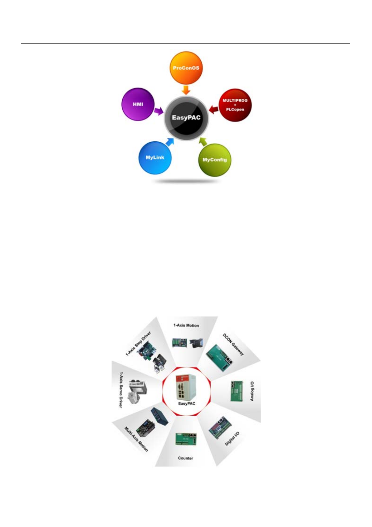
EasyPAC offers complete software and tools:
Built-in ProConOS
MULTIPROG + PLCopen Functional Block. Users are able to customize their own functionalities.
MyConfig: Utility for setting of system parameters.
MyLink: Utility for diagnose Motionnet slave modules.
Communicate between HMI and main system through Ethernet or serial communications.
Page 9
TPM
9
Figure 1-1: EasyPAC offers complete software and tools
EasyPAC User Manual
1.1.2. Compact Size + Motionnet = High Extension and Integration
EasyPAC provides two Motionnet Rings:
Ring_0: For digital I/O, analog I/O and pulse counters.
Supports up to maximum 64 slave modules.
Transfer speed: 2.5/5/10/20 Mbps.
Ring_1: For motion control.
Supports up to maximum 32 axes.
Transfer speed: 2.5/5/10/20 Mbps
Figure 1-2: EasyPAC and supported slave modules
Page 10

TPM
10
EasyPAC User Manual
1.2. Features
Fanless and compact size
Standard PC interfaces: LAN/ USB2.0/ RS-232/ RS-422/ Compact Flash Disk
Microsoft Windows CE5.0 embedded real-time operating system
Local digital I/O interface: DIx8, DOx8
Built-in two Motionnet Masters (Ring_0 and Ring_1)
Ring_0: For digital I/O, analog I/O and pulse counters. Supports up to maximum 64 slave
modules.
Ring_1: For motion control. Supports up to maximum 32 axes.
Configurable Motionnet transfer rate: up to 20Mbps maximum.
Combine HMI (Human Machine Interface) by Modbus-TCP or Modbus-RTU
System utility: MyConfig.
Motionnet utility: MyLink.
Programming software tool: MULTIPROG5.35 Express
Power input spec.
Output voltage: 24V DC
Power Consumption: 7W
1.3. Hardware
The following table shows the hardware specifications of EasyPAC:
TPM EasyPAC Specifications
1. Vortex86DX 800 MHz
2. DDR2 RAM 256 MBytes
3. BIOS Flash 2 MBytes
4. D-SUB 15 Male Connector x 2
5. USB Connector x 2 USB 2.0
6. RJ-45 Connector x 2 Motionnet x 2 (CN3, CN4)
RS-422 x 1, RS-232 x 1 (COM)
RS-422 x 1, RS-232 x 1 (CN 1)
7. RJ-45 Connector x 1 Ethernet (LAN)
8. Hardware Security Hardware IC + AES encryption
9. FRAM 32 KBytes
10. DI/O (Isolation 2.5KVDC) 8 Channel Input / Output
11. CF Card Socket x 1
12. 16 step Rotary Switch x 2
13. 7-segment display x 1
Page 11

TPM
11
TPM EasyPAC Specifications
EasyPAC User Manual
14. LED display x 4
15. Reset Button (PB1) x 1
1.4. Software
There are two utilities provided to diagnose and test EasyPAC, MyConfig and MyLink. In addition to
standard DIO/AIO interfaces, EasyPAC also supports Motion Function Block (Motion FB) used to program
the Motionnet based motion control slave modules connected to Ring_1.
MyConfig: System configuration utility configures IP address, system information etc.
MyLink: A diagnostic utility used to test, set and verify the functionalities of slave modules hooked up
to Motionnet.
Motion FB: Visualized functional block based on MULTIPROG. It supports single and multiple axes.
1.5. Motionnet Devices
EasyPAC is equipped with 2 two Motionnet masters named Ring_0 and Ring_1. Ring_0 is mostly for digital
I/O and analog I/O and Ring_1 is for motion control. The detailed data is in the following table:
Item Specifications
port of Motionnet
Remark
Ring_0 Ring_1
106-D240-NX 32-ch digital input with NPN Yes No
106-D222-NN 16-ch digital input and 16-ch digital output with NPN Yes No
106-D204-XN 32-ch digital output with NPN Yes No
106-D440-NX 32-ch digital input with NPN Yes No
106-D422-NN 16-ch digital input and 16-ch digital output with NPN Yes No
106-D404-XN 32-ch digital output with NPN Yes No
106-D520-NX 16-ch digital input with NPN Yes No
106-D502-XN 16-ch digital output with NPN Yes No
107-D140-NX 32-ch digital input with NPN Yes No
107-D122-NN 16-ch digital input and 16-ch digital output with NPN Yes No
107-D104-XN 32-ch digital output with NPN Yes No
EZM-D140-NX 32-ch digital input with NPN Yes No
EZM-D122-NN 16-ch digital input and 16-ch digital output with NPN Yes No
EZM-D104-XN 32-ch digital output with NPN Yes No
106-A104-01 4-ch analog output (±10V) Yes No
106-A180-01 8-ch analog input (±10V, ±5V, ±2.5V, ±1.25V) Yes No
Page 12

TPM
12
EasyPAC User Manual
port of Motionnet
Item Specifications
Ring_0 Ring_1
108-A122 8-ch analog input and 4-ch analog output Yes No
Remark
108-G180 DCON Gateway Yes No
108-P120 4-ch, 32 bites up-down counter Yes No
102-M1x1 1-axis Motion connector series No Yes
BCD-4020FU 1-axis 2-phase stepper driver No Yes
BCD-4020FB 1-axis Micro stepper driver No Yes
Ezi-Servo close-loop stepper driver No Yes
Kingservo King servo motor & driver No Yes
Table 1-1: Motionnet compatible devices
coming soon
coming soon
coming soon
Page 13
TPM
13
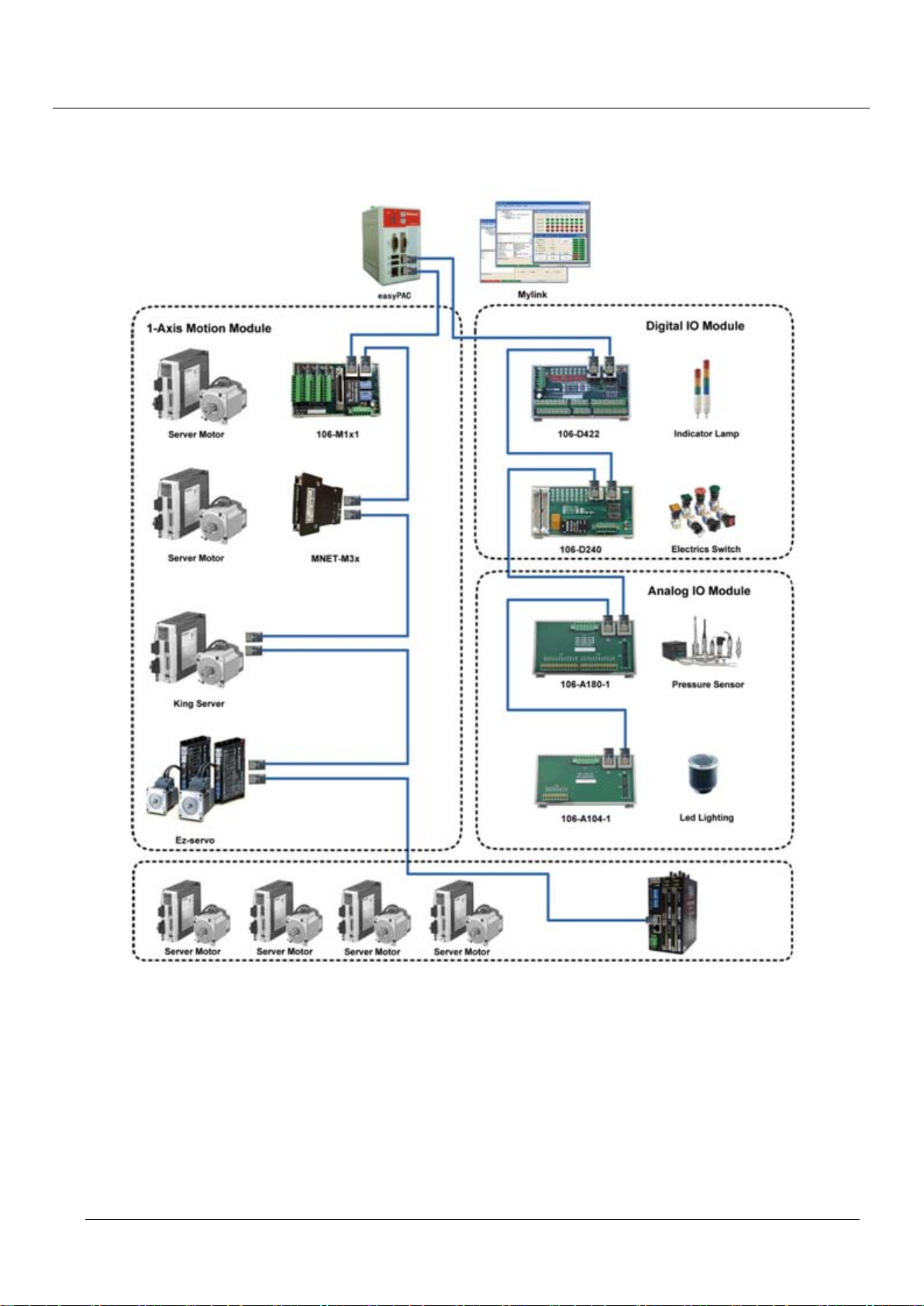
1.6. System Architecture
EasyPAC User Manual
Figure 1-3: EasyPAC system architecture
1.7. 24V DC Power Module
Features:
Universal AC input / Full range
Protections: Short circuit / Overload / Over Voltage
Page 14

TPM
14
Cooling by free air convection
Can be installed on DIN rail TS-35 / 7.5 or 15
NEC class 2 / LSP compliant
LED indicator for power on
DC OK relay contact
No load power consumption < 0.75W
100% full load burn-in test
Safety standards: CE / UL / RU
EasyPAC User Manual
Page 15
TPM
15
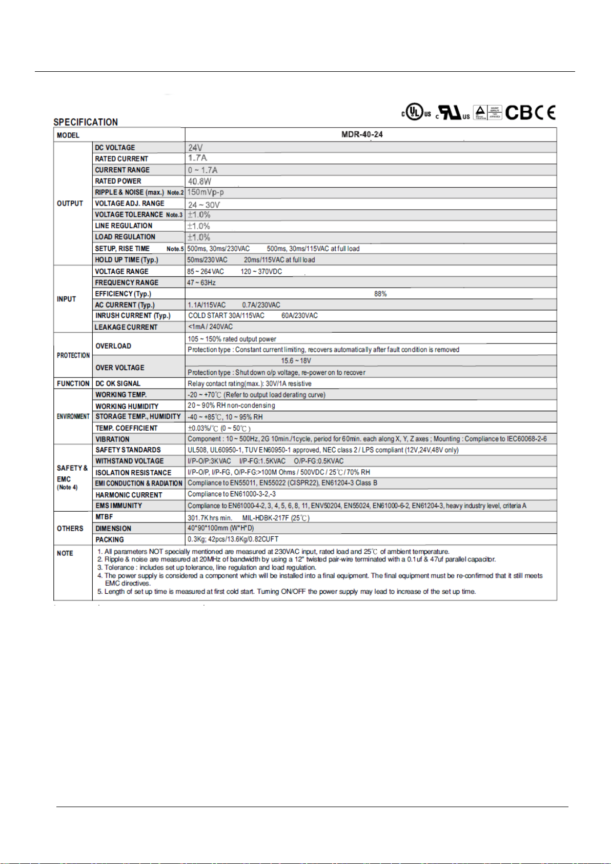
The detailed hardware specification is listed as the following table:
EasyPAC User Manual
Table 1-2: hardware specification
1.8. Package List
Package list is as below:
EasyPAC EPC-1100
Specific power module
System CF card with built-in software license (WinCE5.0 / ProConOS)
Product CD (Including: manuals and installation tools)
Page 16

TPM
16
EasyPAC User Manual
Note that if you have any question for package, please contact our local distributor or register on our web-site.
We will offer the new library, template and demo programs.
Page 17
TPM
17
2. Hardware Installation
2.1. Dimension
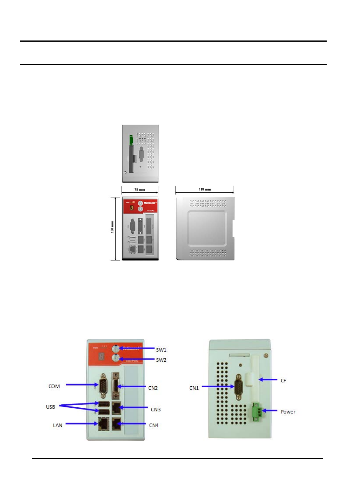
The outline dimension of EasyPAC is shown below.
EasyPAC User Manual
Figure 2-1: outline and dimension
2.2. Connectors
All connectors and switches of EasyPAC are shown below.
Figure 2-2: Connections of EasyPAC
Page 18
TPM
18
Name Function
COM D-SUB COM port (COM1/COM3) connector
CN1 D-SUB COM port (COM2/COM4) connector
CN2 SCSI-20Pin Digital I/O connector
CN3 RJ-45, expanding connector of Motionnet DI/O and AI/O
CN4 RJ-45, expanding connector of Motionnet Motion
Power 3 Pin connector
CF Extension slot of CF
USB Standard USB 2.0connector
LAN RJ-45, LAN 10/100
SW1 System operating mode setting
SW2 Baud rate of Motionnet setting
Table 2-1: EasyPAC connectors and switches
2.2.1. COM Port – COM & CN1
EasyPAC User Manual
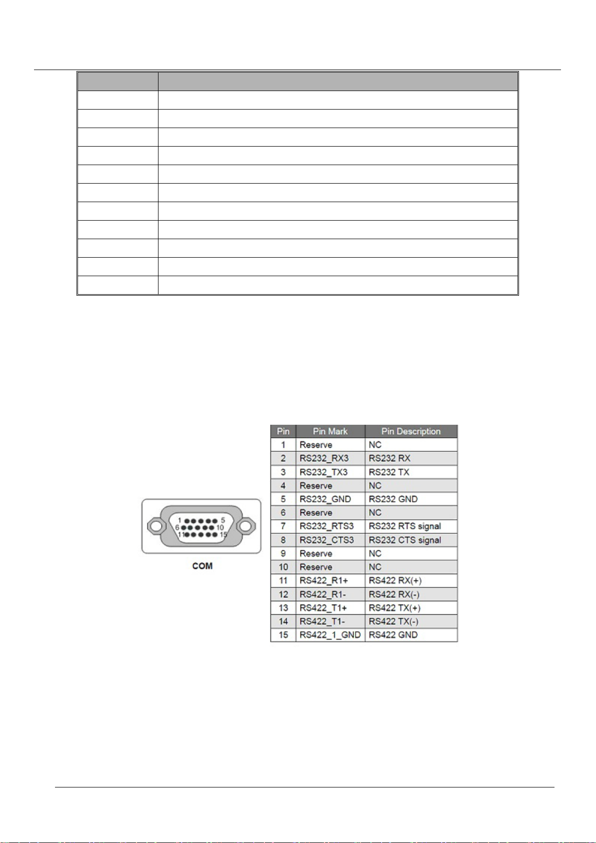
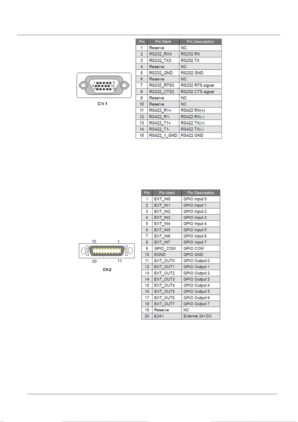
EasyPAC is equipped with four COM ports, two RS-232 and two RS-485. They are deployed in COM (COM1
RS-422 & COM3 RS-232) and CN1 (COM2 RS-422 & COM4 RS-232) separately that is the D-SUB 15-pin
connector. The pin definition of this connector is in the following:
Figure 2-3: COM port pin assignme nt
Page 19
TPM
19
Figure 2-4: CN1 pin assignment
2.2.2. GPIO – CN2
EasyPAC User Manual
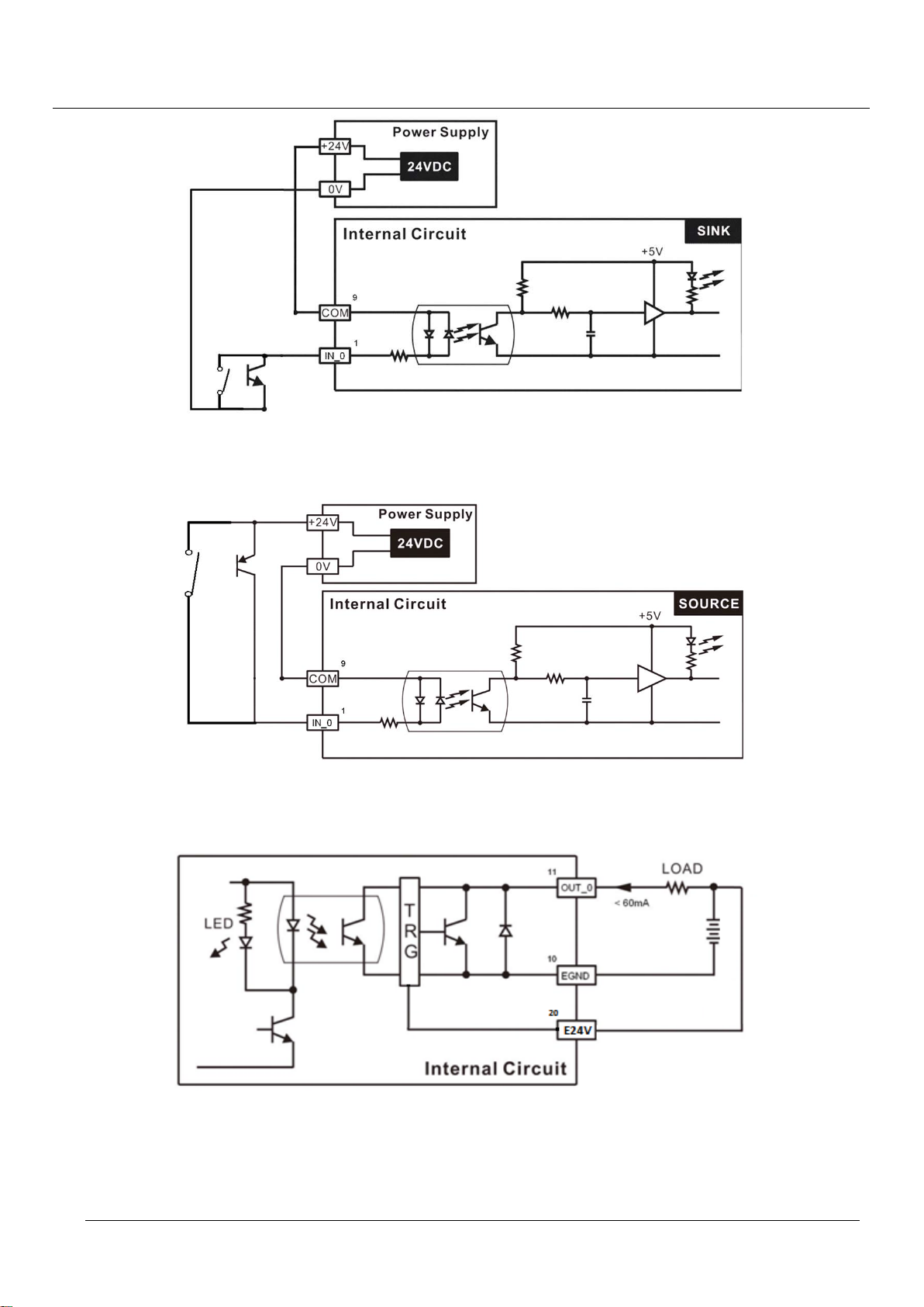
The pin definition of this 8DI/ 8DO connector is shown below:
Figure 2-5: pin assignment of CN 2
Digital GPIO input signal circuit in SINK mode (NPN) is illustrated as follows.
Page 20
TPM
20
Figure 2-6: signal circuit of input NPN
Digital GPIO input signal circuit in SOURCE mode (PNP) is illustrated as follows.
EasyPAC User Manual
Figure 2-7: signal circuit of input PNP
Digital GPIO output signal circuit in SINK mode (NPN) is illustrated as follows.
Figure 2-8: signal circuit of output NPN
Page 21
TPM
21
EasyPAC User Manual
2.2.3. Ring_0 – CN3
The Ring_0 of Motionnet on CN3 is used for digital input/ output and analog input/ output slave modules. The
pin definition of this connector is in the following:
Pin Pin Mark Pin Description
1 NC Reserved
2 NC Reserved
3 RS485+ Motionnet protocol +
4 NC Reserved
5 NC Reserved
6 RS485- Motionnet protocol 7 NC Reserved
8 NC Reserved
Table 2-2: pin assignment of CN3
2.2.4. Ring_1 – CN4
The Ring_1 of Motionnet on CN4 is used for motion control slave modules. The pin definition of this
connector is in the following:
Pin Pin Mark Pin Description
1 NC Reserved
2 NC Reserved
3 RS485+ Motionnet protocol +
4 NC Reserved
5 NC Reserved
6 RS485- Motionnet protocol 7 NC Reserved
8 NC Reserved
Table 2-3: pin assignment of CN4
Page 22
TPM
22
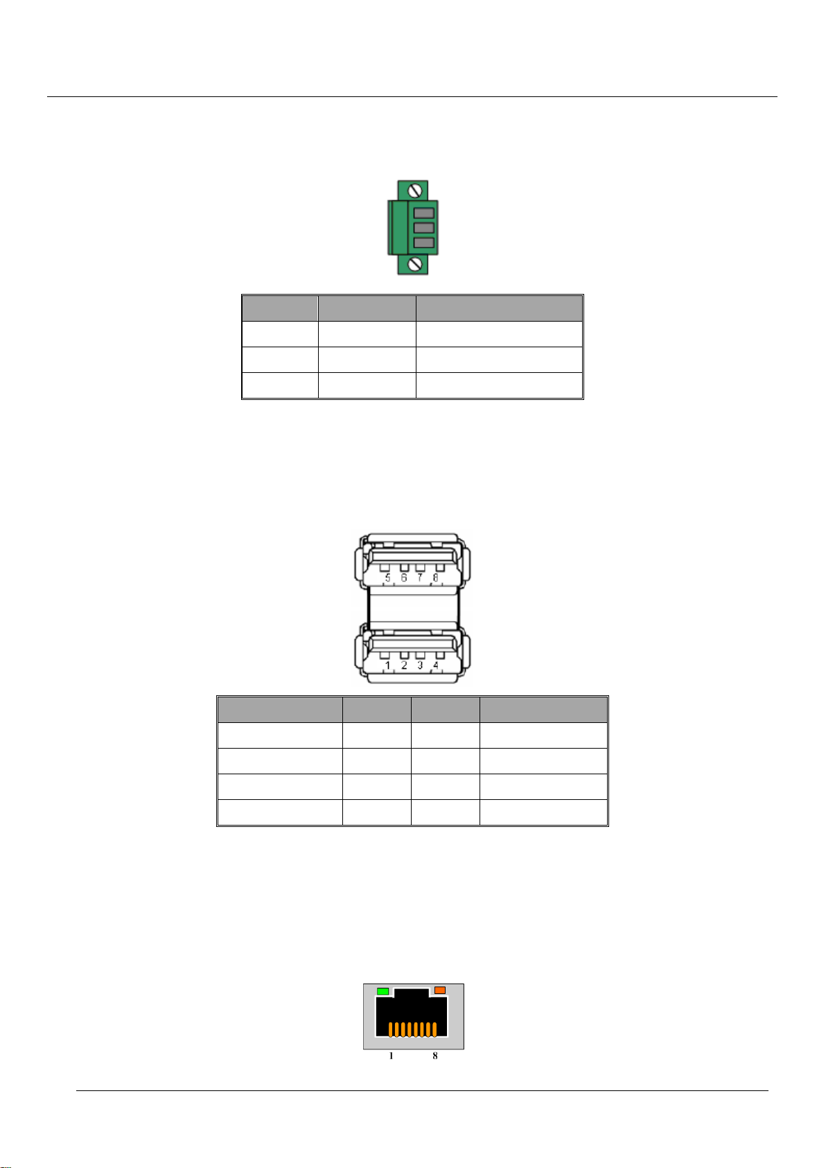
2.2.5. 24V DC Input
Pin definition of this connector is in the following.
Pin Pin Mark Pin Description
1 24 Power 24V
2 0 GND
3 FG Frame GND
Table 2-4: main power connector pin assignment
2.2.6. USB Connector
EasyPAC User Manual
There are two sets of USB in the EasyPAC. The pin definition of this connector is in the following:
USB signal pin pin USB signal
Vcc 1 5 Vcc
USB_D0- 3 6 USB_D1-
USB_D0+ 5 7 USB_D1+
Ground 7 8 Ground
Table 2-5: USB connector pin assignment
2.2.7. LAN Connector
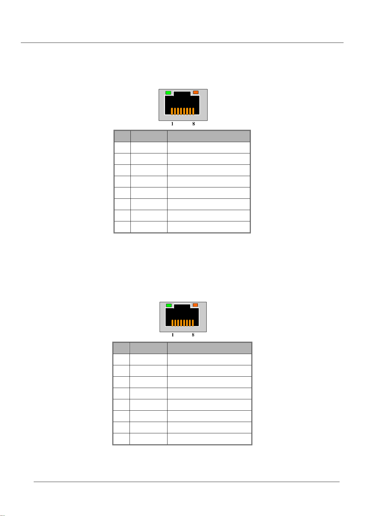
EasyPAC provides one LAN port with 10/100Mpbs. The default IP address is 192.168.1.100 and user can
modify it with MyConfig. The pin definition of this connector is in the following:
Page 23

TPM
23
EasyPAC User Manual
Table 2-6: LAN connector pin assignment
2.3. Rotary Switch
There are two rotary switches on EasyPAC. One is to set the run mode of system and the other is to set the
baud-rate of Motionnet.
2.3.1. System Mode Setting – SW1
The SW1 is used to set the mode of EasyPAC. User can choose the system mode by setting SW1. The
corresponding setting of this switch is in the following:
SW1
0 MyConfig Server Mode Set default IP address 192.168.1.100
1 MyConfig Server Mode
2 MyLink Server Mode
3 Backup Backup whole system to CF card
4 Restore System restore from CF card
5 Reserve Reserve
6 Reserve Reserve
7 KW Mode + Modbus Slave over RTU Cold
8 KW Mode + Modbus Slave over RTU Stop
9 KW Mode + Modbus Slave over RTU Warm
A KW Mode + Modbus Slave over TCP Cold
B KW Mode + Modbus Slave over TCP Stop
Operating Mode Details
C KW Mode + Modbus Slave over TCP Warm
D KW Mode Cold
E KW Mode Stop
F KW Mode Warm
Table 2-7: SW1 assignment
Page 24
TPM
24
EasyPAC User Manual
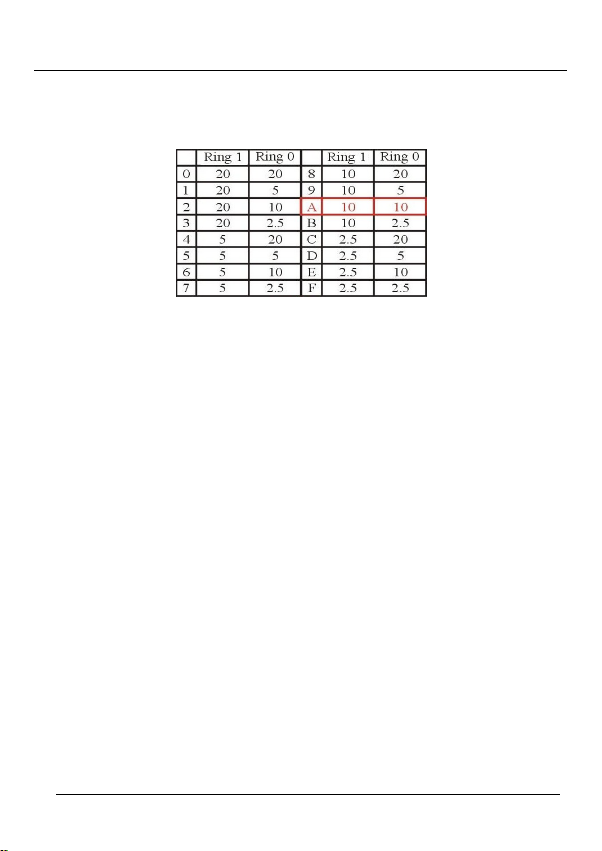
2.3.2. Motionnet Baud-Rate – SW2
The SW2 is used to set the baud-rate of Motionnet Rings. User can choose the baud-rate by switching SW2.
The definition of this switch is as followed: The default setting is: Ring_0: 10Mpbs, Ring_1: 10Mbps.
Table 2-8: SW2 assignment
Page 25

TPM
25
EasyPAC User Manual
3. System Backup and Recovery
EasyPAC provides a function for users to back up the whole system in a storage device and recover the
system from the storage. Following are the step-by-step procedure to do backup and recovery.
3.1. System Backup
Backup files in personal computer
Manually copy the whole folders and files in C:\TPM\EasyPAC\ to a storage device.
Backup EasyPAC system
It only needs 3 steps to back up the EasyPAC system.
1. Insert the CF card.
2. Switch the rotary switch RSW1 to number 3.
3. Power up the EasyPAC system and the backup procedure will be automatically brought up. The
backed up files would be stored at an auto-generated folder EPCBACKUP\.
A short beep means the backup procedure finished successfully.
A long beep means failures occurred and with an “E” on 7-seg display.
3.2. System Recovery
Recover the PC files
Manually retrieve files in C:\TPM\EasyPAC\
Recover the EasyPAC system
It needs 4 steps to recover the EasyPAC system from a storage device.
1. Insert the CF card with backed up files.
2. Switch the rotary switch RSW1 to number 4.
3. Power up the EasyPAC system and the recovery procedure will be automatically brought up. The
necessary backed up files would be retrieved from the folder EPCBACKUP\.
A short beep means the recovery procedure finished successfully.
A long beep means failures occurred and with an “E” on 7-seg display.
4. Reboot to finish the recovery procedure.
Page 26
TPM
26
EasyPAC User Manual
4. Motionnet Introduction
4.1. What Is Motionnet?
Motionnet is a super high-speed serial communication system. The G9000 devices provide input/output
control, motor control, CPU emulation and message communication with high speed serial communications
(up to 20Mbps) all of which are required by current Factory Automation techniques. Motionnet always
transfers 4 bytes of data in 15.1μsec using cyclic communication to control input and output. While this data is
being transferred, it can communicate at maximum of 256 bytes, such as motor control data. Communication
times can be calculated using formulas, allowing users to see that Motionnet guarantees the real-time oriented
support needed by FA industries.
4.2. Motionnet Functions
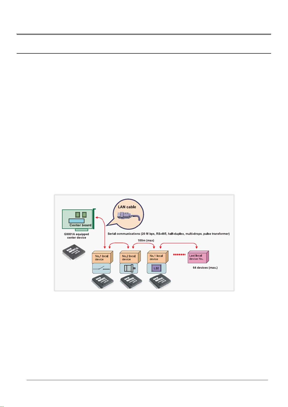
Figure 4-1: Motionnet system architecture
Provides a communication protocol based on the RS485 standard.
Can communicate variable length of data from 1 to 128 words (when a 16-bit CPU is used)
An LSI center device (G9001) controls the bus.
I/O wiring can be greatly reduced by using a G9002 I/O device.
Motor control wiring can be reduced by using a G9003 PCL.
Using a G9004 CPU emulation device reduces the wiring for general devices connected to a CPU. Data
can be exchanged between CPUs by changing the G9004 mode.
New devices can be added to the system on the fly.
Page 27
TPM
27
ACTU ATOR
ACTUATOR
ACTUATOR
ACTUATOR
ACTUATOR
SENSOR
SENSOR
SENSOR
SENSOR
SENSOR
SENSOR
SENSOR
SENSOR
Extension
Master
Analog I /O
Digital I /O
Motion
ACTU ATOR
ACTUATOR
ACTUATOR
ACTUATOR
ACTUATOR
SENSOR
SENSOR
SENSOR
SENSOR
SENSOR
SENSOR
SENSOR
SENSOR
100m
Motion.NET
WIRE-SAVING / LONG-DISTANCE
ACTUATOR
ACTUATOR
ACTU ATOR
ACTUATOR
ACTUATOR
MOTOR
ACTUATOR
ACTUATOR
ACTU ATOR
ACTUATOR
ACTUATOR
MOTOR
EasyPAC User Manual
Systems can be isolated using pulse transformers.
Transfer speed up to 20 Mbps.
Maximum 64 slave devices for each serial line on a master device. Input/output control of up to 256 ports
(2048 points), motion control of up to 64 axes.
Input/output and status communication time for each device when inputting/outputting and reading
status data for each device, the system automatically refreshes the center device RAM each
communication cycle. (Cyclic communication: 15.1 µsec./local device) When 32 local devices are
connected (1024 points of input/output): 0.49 msec. When 64 local devices are connected (2048 points of
input/output): 0.97 msec.
Data communication time cyc lic communication can be interrupted with a command from the CPU. Data
communication time: 19.3 µsec. to send or receive 3 bytes (e.g. when writing feed amount data to the
G9003). Data communication time: 169.3 µsec. to send or receive 256 bytes.
Serial communication connection cable. Multi-drop connections using LAN cables or dedicated cables.
T otal ca ble length of one line: 100 m (20 Mbps/32 local boards) (10 Mbps/64 local boards). Cable length
between local boards: 0.6 m or longer.
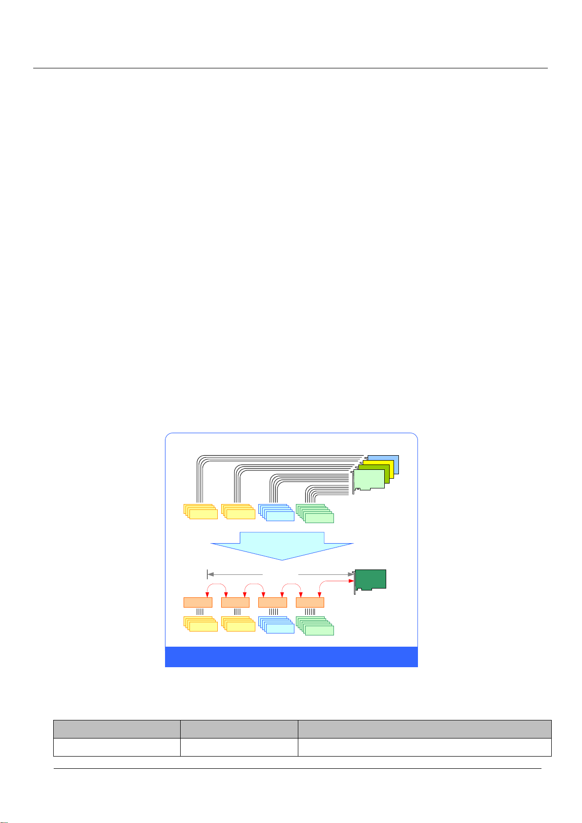
4.3. Advantage of Motionnet
It is possible to connect from center to terminal controller parts by one cable.
Figure 4-2: wire-saving and long-distance support
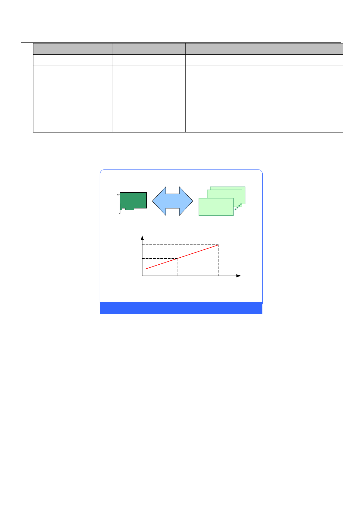
In cyclic communication, a communication cycle is as follows when a 20 Mbps speed is selected.
Number of local devices Communication cycle Remarks
8 0.12 ms If all of the local devices connected are I/O devices,
Page 28
TPM
28
Master
Slave Module
x 64 Slave
20Mbps
6432
0.56ms
1.04ms
NODE
CYCLE TIME
HIGH-SPEED / TIME-DETERMINISTIC
512-DI / 512-DO 1024-DI / 1024-DO
64 Slaves < 1.04ms
On 20Mbps, Max. Cycle Time = 15.1 x NODE + 71.4 [FIFO Time] in us
EasyPAC User Manual
Number of local devices Communication cycle Remarks
256 input/output points can be used.
16 0.24 ms If all of the local devices connected are I/O devices,
512 input/output points can be used.
32 0.49 ms If all of the local devices connected are I/O devices,
1024 input/output points can be used.
65 0.97 ms If all of the local devices connected are I/O devices,
2048 input/output points can be used.
If a different number of local devices are connected, or when the communication cycle is interrupted by data
communications, refer to the calculation formulas in the user's manual to calculate the time latency.
Figure 4-3: high-speed and ti me deterministic support
Page 29
TPM
29
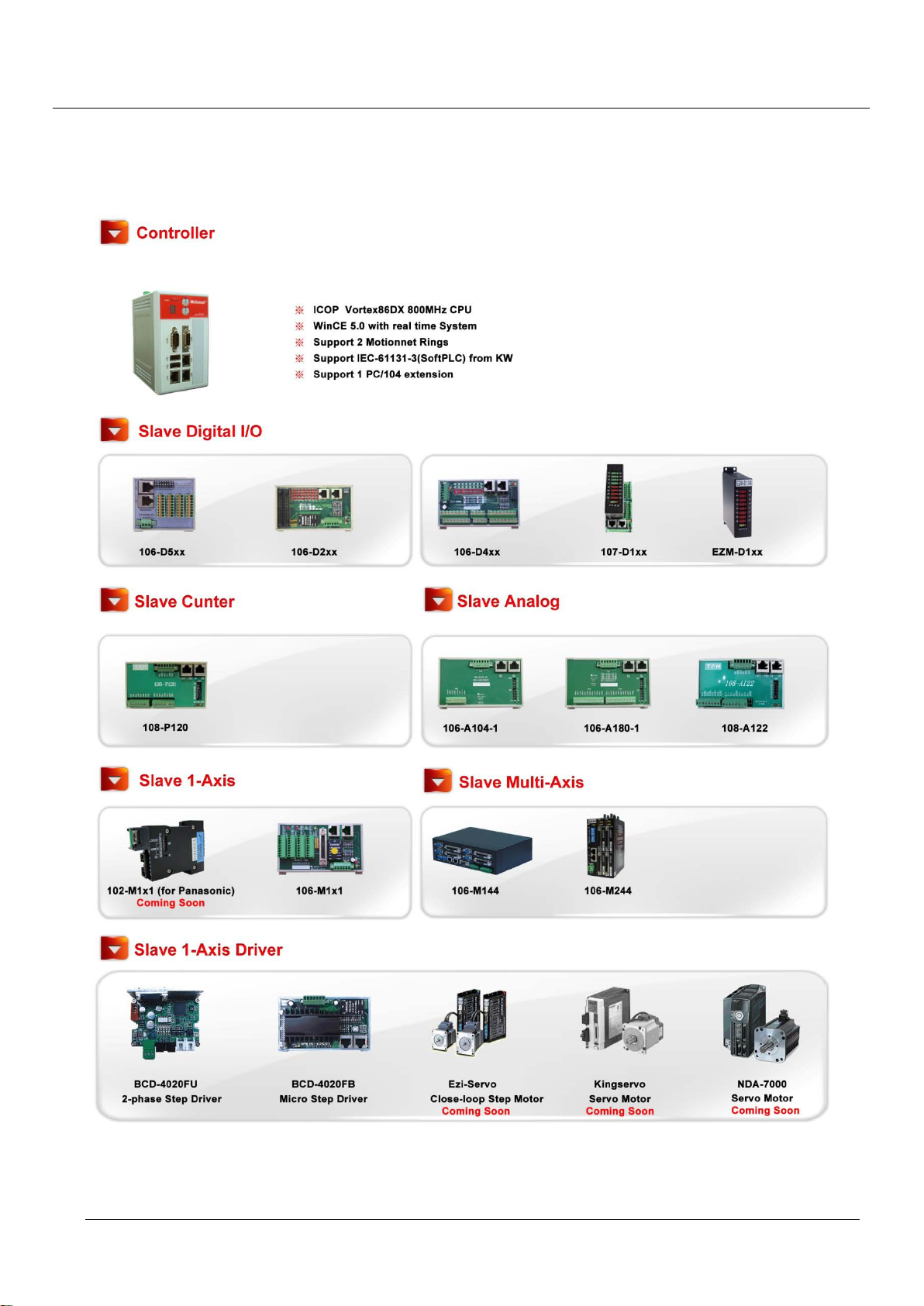
4.4. Motionnet Prod uct Fami ly
EasyPAC User Manual
Figure 4-4: EasyPAC and Motionnet product family
Page 30

TPM
30
EasyPAC User Manual
5. Software Utilities
3 different software utilities are developed to help users easily make use of EasyPAC:
1. MyConfig
2. MyLink
3. MyDataCheck
5.1. MyConfig
MyConfig is a software utility designed for EasyPAC. Besides providing basic hardware information,
MyConfig also support online update so that users could set and view the hardware status though Ethernet.
Recommended Hardware Requirement
PC Hardware: PC or laptop with Intel Centrino or above CPU
Memory: 1GB RAM
OS: Windows XP or Win7
LAN card: RJ-45 10/100/1000 Mbps
Software Installation
EasyPAC needs 2 files: MyConfigSvr.exe and EZPACSDK.dll
PC needs 1 file: MyConfig.exe
5.1.1. Server on EasyPAC
Before powered up EasyPAC, please make sure the SW1 is switched to position 1. PC is supposed to have
the same network section as EasyPAC (IP address: 192.168.1.100) when the network cable is hooked up. If
these two settings are correct, we can power up the EasyPAC. It will beep an alert sound if the system is
successfully brought up and MyConfigSrv.exe will be started automatically. If there is no beep for a while
means Ethernet failure or the IP address is in conflict with someone else.
5.1.2. PC Side Settings
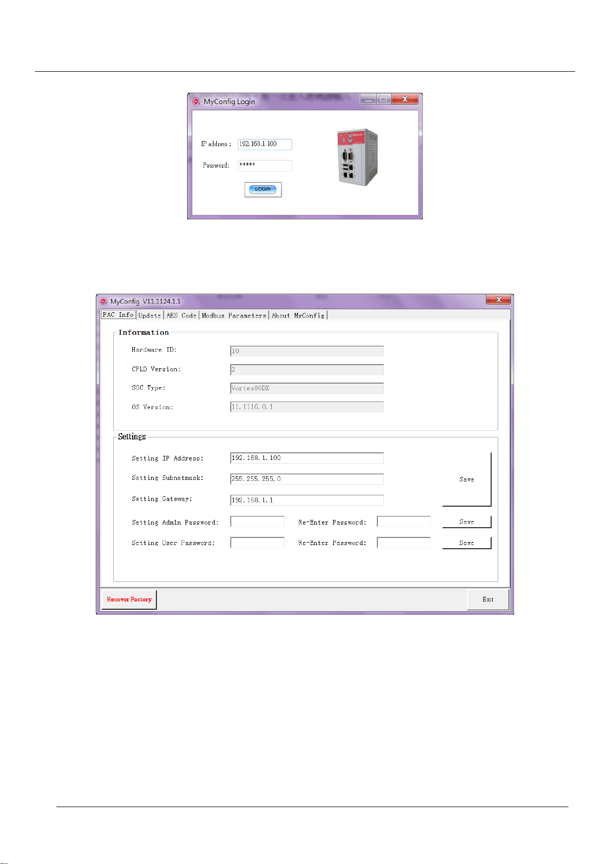
5.1.2.1 Login
Users can login MyConfig with EasyPAC IP address and password. MyConfig provides two kinds of login
account which have different privilege. Default password for administrator is admin and default password
for guest is guest. The password could be updated after login. The administrator has the privilege to view
and change settings and the guest only could view the current settings. Please sign in as admin at the first
Page 31
TPM
31
EasyPAC User Manual
time logging in.
Figure 5-1: MyConfig login page
After logging in, there are five more tabs – PAC info, Update, AES code, Modbus parameters and About
MyConfig.
Figure 5-2: system information of EasyPAC
5.1.2.2 PAC Info
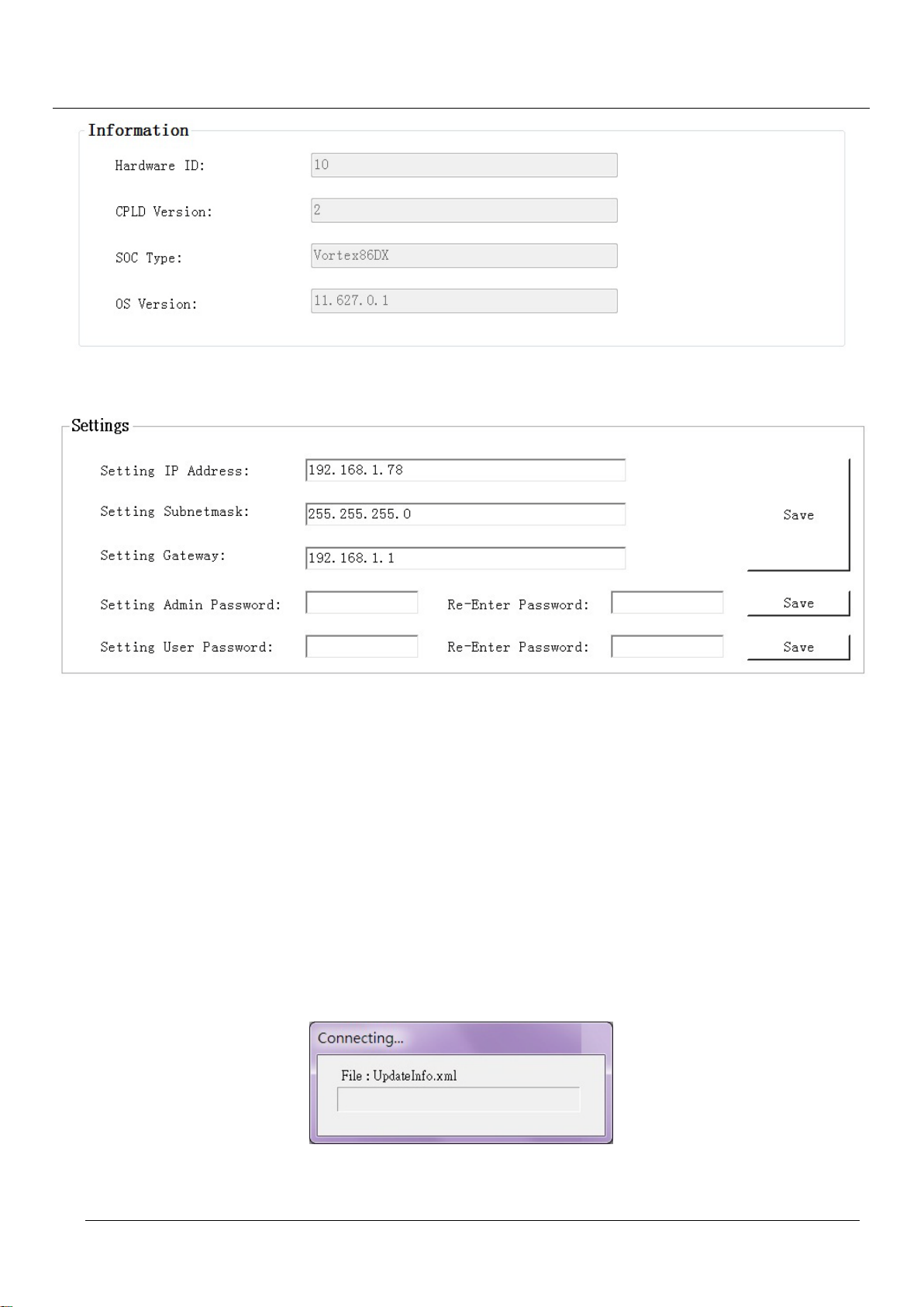
Users can see the EasyPAC basic hardware information at the top half of the page. At the bottom half, users
could set up IP address, subnet mask, gateway, admin password and guest password.
Page 32
TPM
32
Figure 5-3: Hardware basic information
EasyPAC User Manual
Figure 5-4: change settings of IP, subnet mask, gateway, admin and guest password
Note that only if the user is in the same network section can change the EasyPAC IP address. The IP address,
subnet mask and gateway settings could be saved if the “Save” button is hit and will take effect after
restarting the system. The admin and guest password would change immediately when new a password is
input and “Save” button is pressed.
5.1.2.3 Update
It provides online software update. Please make sure the PC is connected to the internet before online update.
If the “Check for Updates” button is pressed, it will show up the software versions on EasyPAC and user’s
PC at the top half. At the bottom half shows the latest software versions provided from TPM.
Figure 5-5: connect to FTP server
Page 33
TPM
33
EasyPAC User Manual
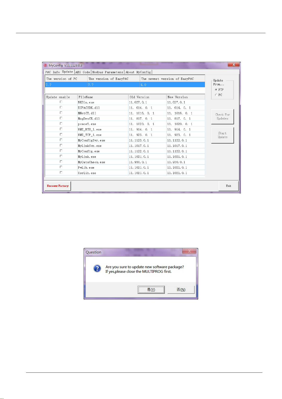
The upper frame shows information including 1: PC side version, 2: EasyPAC side version and 3: the latest
version in FTP site. If the older version displays “?.?” indicates there is one or more components do not
match with the newer version ones.
Figure 5-6: update software page
In this “Update” tab, it would show up the software versions that are out of date. There is also a hint
message informing software needs to be updated. Before doing the updating, please make sure that the
MULTIPROG application must be closed. There would be errors on overwriting files if the MULTIPROG is
not closed which leads to updating failure.
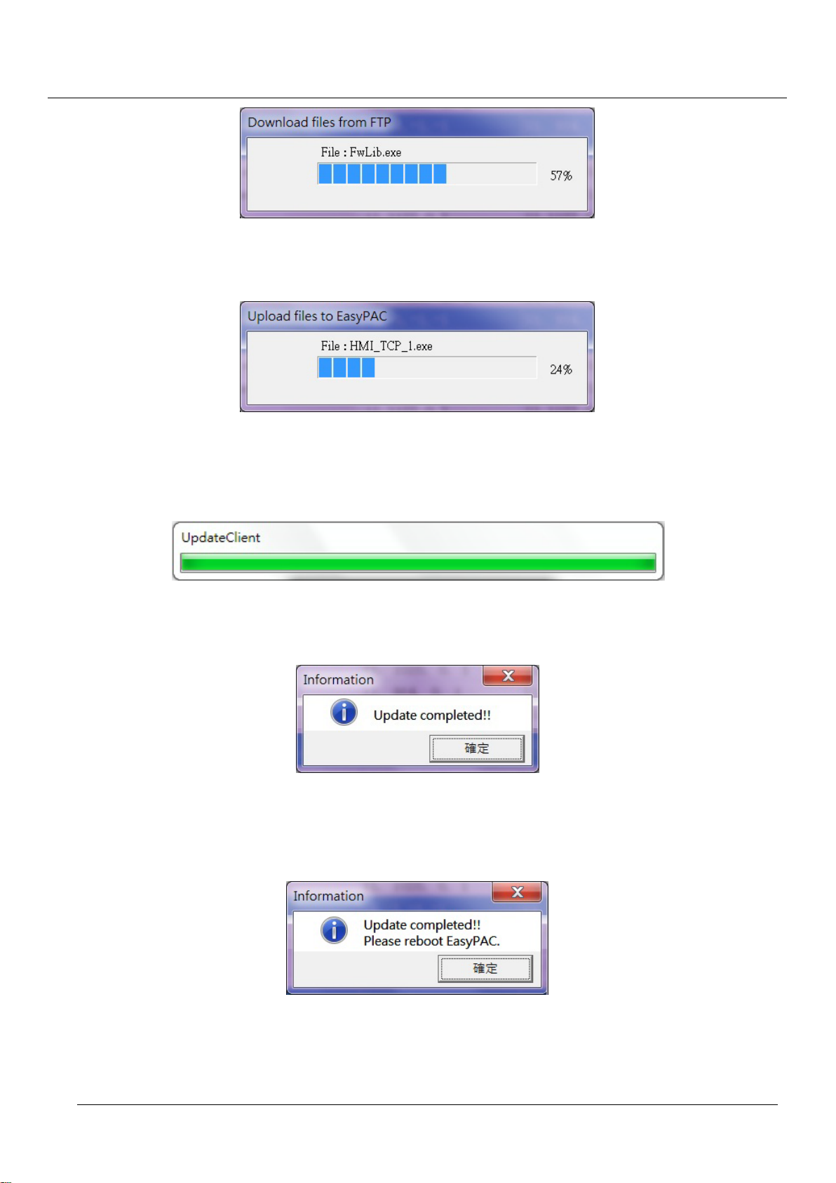
Figure 5-7: reminder of closing MULTIPROG
After OK button is pressed, MyConfig starts connecting to the FTP server and downloading files.
Page 34
TPM
34
EasyPAC User Manual
Figure 5-8: download from FTP
Upload to EasyPAC.
Figure 5-9: update to EasyPAC
Select files needed to be updated and press the “Start Update” button and then it will start updating and
pop-up a progress bar like below.
Figure 5-10: progress bar of software updating
If the update includes PC only, the following dialog will pop up.
Figure 5-11: update complete dialo g
If the software update completes including EasyPAC, it will pop up a dialog saying the update completed.
EasyPAC needs to reboot to apply new software.
Figure 5-12: update complete dialo g
Page 35
TPM
35
EasyPAC User Manual
5.1.2.4 AES Code
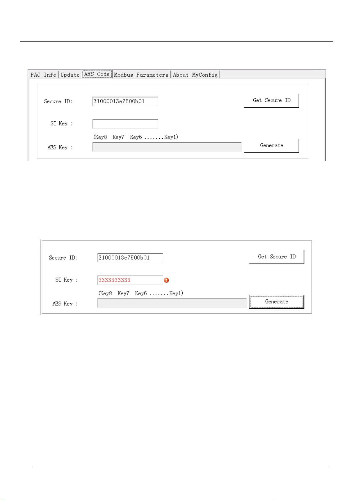
Figure 5-13: dialog window for generating AES key
Secure ID: display the hardware id of the EasyPAC. Moreover, the system integrator could input the
hardware id of other EasyPAC in the “Secure ID” text box to generate the corresponding AES key.
EasyPAC provides an AES key encryption mechanism to protect our customers. The SI key is supposed to
be 16 numeric digits. If the SI key is not 16 digits or it contains non-numeric digits, an error message will
show up as figure below.
Figure 5-14: insufficient digits
5.1.2.5 Modbus Parameter
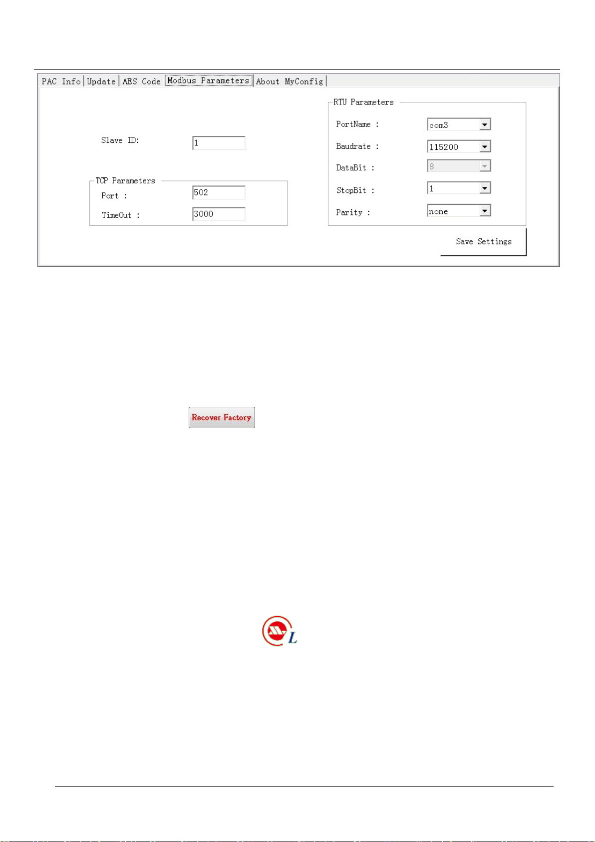
The “Modbus Parameters” page let users edit Modbus related parameters for KW applications of EasyPAC.
Modbus requires settings of slave ID, TCP and RTU parameters. MyConfig provides sets of default settings
in advance. Users can change the settings and press the “Save Settings” button to transmit the settings to
EasyPAC.
Next time when users login to MyConfig, the settings set last time or the default values will be shown in the
Modbus parameters page. Users can always login to check in this page. This page is shown in the following
figure.
Page 36
TPM
36
Figure 5-15: setting of Modbus parameter dialog
5.1.2.6 Recover Factory Default Settings
EasyPAC User Manual
If users forget the changed password of admin or guest, or the changed settings of the IP, Modbus, etc is not
working, a solution is to recover factory settings. The step-by-step recovery from factory settings is as
follows:
1. Press the recovery button and then reboot.
2. The EasyPAC would roll back to the default IP address: 192.168.0.100. Now we could connect to it
with MyConfig.
3. The “PAC info” tab has previous set IP address shown in “Saved IPAddress”.
5.2. MyLink
MyLink is utility software used to test, diagnose and verify the functions of the remote Motionnet slave
modules. The following slave modules are available: DIO、AIO、Counter and Axis modules. After
successful installation, MyLink.exe with icon could be found in the remote PC.
Recommended Hardware Requirement
PC Hardware: PC or laptop with Intel Centrino up CPU
Memory: 1GB RAM
OS: Windows 2000/XP/Win7
LAN card: RJ-45 10/100/1000 Mbps
Software Installation
Page 37
TPM
37
EasyPAC User Manual
1 executable file: MyLink.exe
5.2.1. Interface
Login
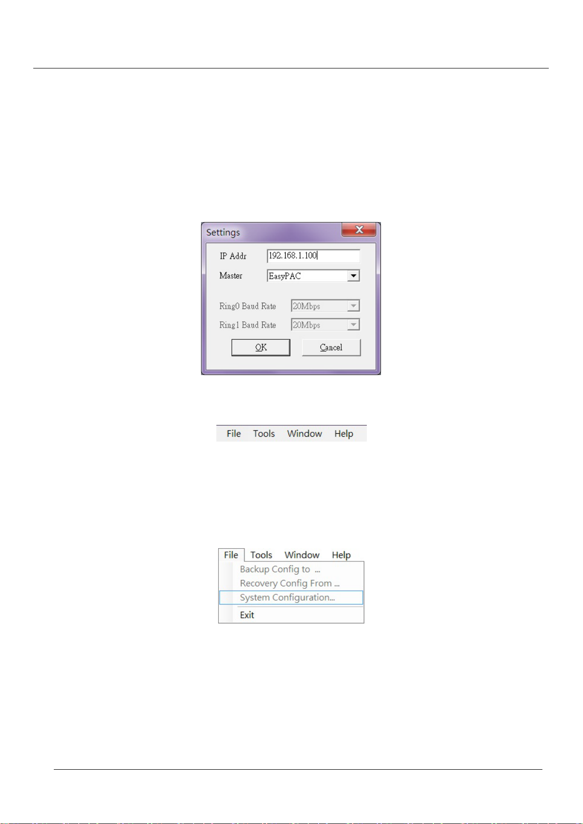
The supported master contains two kinds of devices – EasyPAC and USB-L131. If users select USB-L131,
the baud rate option of Ring_0 and Ring_1 would be enabled. If users select EasyPAC as the master device,
the baud rate would keep disabled since that is set by switching the rotary switch (SW2) on the front side of
EasyPAC.
Figure 5-16: screenshot of settings
Tool Bar
Figure 5-17: MyLink main functions
There are 4 main functions in the tool bar.
File
This is used for file access especially for KW. Also this is used to set and save of axes module
parameters or copy the parameters for other axes.
Figure 5-18: functions under file o ption
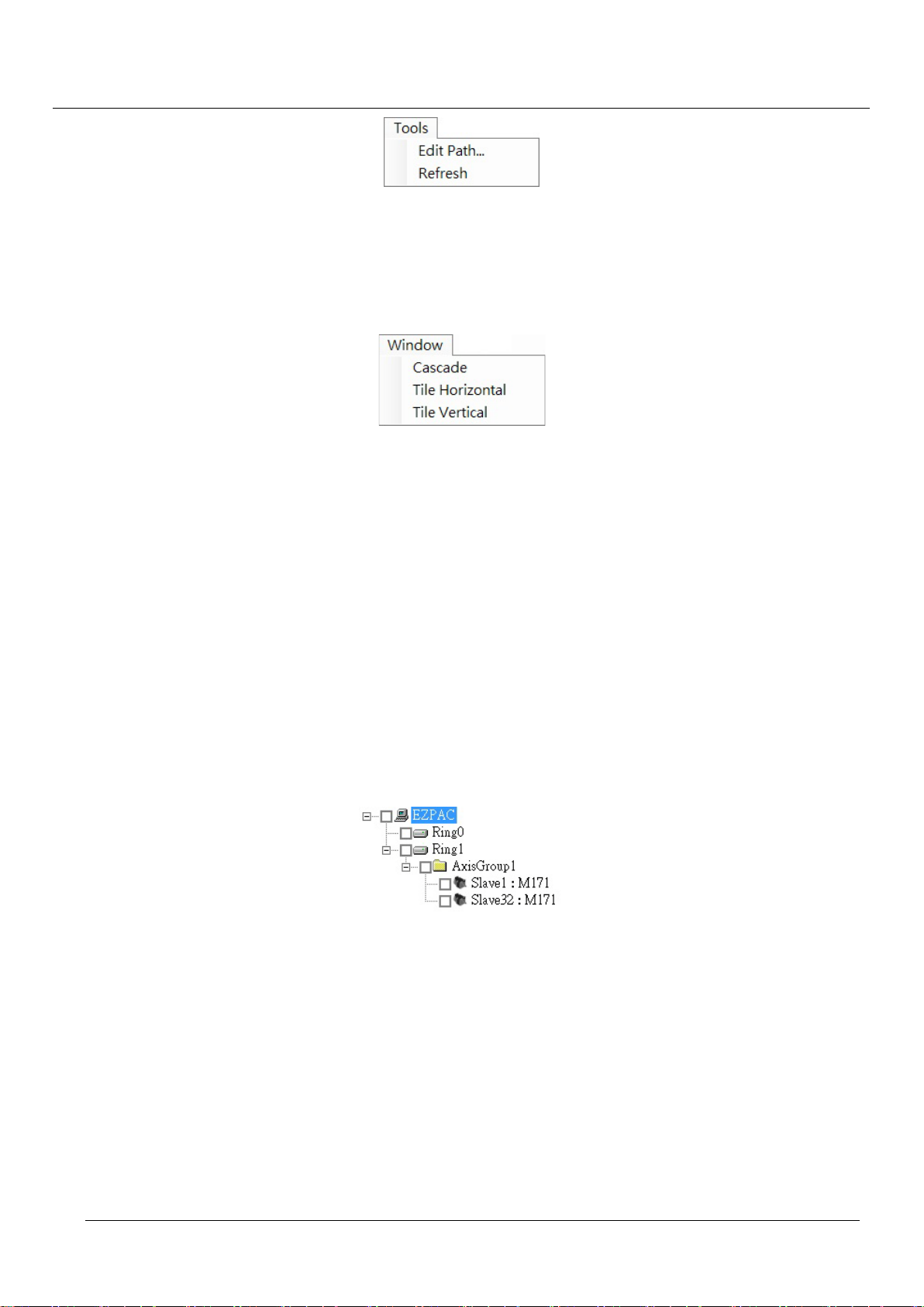
Tools
Provides functions for setting system parameters and initialize the system. There are 2 sub-functions:
1. Edit Path…: this option is only available when two axes module are grouped up. Later we will
discuss about the “Group” function.
2. Refresh: this function provides users to rescan all the devices connected to the MyLink server after
adding, removing or replacing Motionnet slave modules without the need of restarting MyLink.
Page 38
TPM
38
EasyPAC User Manual
Figure 5-19: functions under tools option
Windows
When multiple slave modules are displayed in the same time, the related menu will be re-arranged
accordingly.
Figure 5-20: functions under window option
Help
This shows the MyLink revision number.
5.2.2. Module Status
After clicking the initial button, the found and identified slave modules will be shown accordingly. Click the
check box in front of the slave module and the corresponding menu will pop-up. Except USB-L131, it will
show up two Motionnet masters at the top left corner – Ring_0 and Ring_1. If the master is EasyPAC,
MyLink could save the profile according to data type designated for KW. Moreover, the slave modules
besides axes control are supposed to connect to Ring_0 and axes control is supposed to connected to Ring_1.
Check the slave device at the check box will pop up the corresponding control window at the main frame of
MyLink and the properties will show at the left bottom corner.
Figure 5-21: slave devices found by the Motionnet master
Properties
The related item will be shown accor ding to the selected slave module type. If the property is grayed out
means it is read only.
Page 39
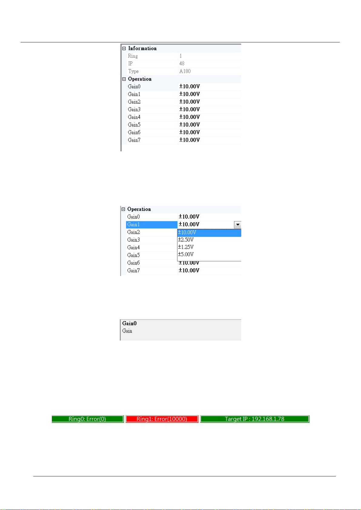
TPM
39
EasyPAC User Manual
Figure 5-22: the property window
If the parameter comes with a combo box means the input options are pre-arranged. If the input is a text
box, users should key in the value needed within the acceptable range. The combo box for a parameter
is shown as the following figure.
Figure 5-23: screenshot of updating properties
Description
This is located below the property page. The main purpose is illustration and suggestion.
Figure 5-24: property description
Ring Status
Ring status is shown in the bottom. Green means the ring is initialized successfully without error and
red means the ring is in error state. The number within the parenthesis represents the number of
communication failure. The ring status will be in red if there is no slave modules connected to the ring
or the communication retry time reaches the maximum limit (10000).
Figure 5-25: Ring status
Message
There is a block above the ring status displaying responses from MyLink. The responses include time
stamp the event occurred and error or hint messages.
Page 40
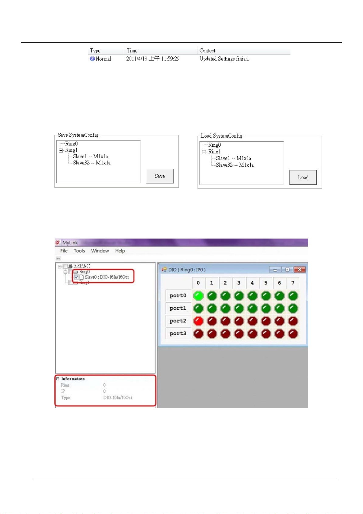
TPM
40
EasyPAC User Manual
Figure 5-26: message box information
System Configuration
The current connected slave module would be displayed in the system config area with 0 < IP < 33. It
saves the system config structure in EasyPAC once the Save button is pressed. It would load the system
structure from EasyPAC when the Load button is pressed.
Figure 5-27: load and save of the system configuration
5.2.3. DIO Module Operation
Figure 5-28: information of connected devices
Module Status
As shown in the above menu, a DIO module is identified in Ring 0. This example is a 16 input /16 output
module.
Property
Page 41
TPM
41
EasyPAC User Manual
No setting is required for DIO module.
Operation
The DO is connected with DI in the illustrated DIO module accordingly. When turn on the DO channel,
both the DO and corresponding DI are ON.
5.2.4. AIO Module Operation
5.2.4.1 A104 & A180
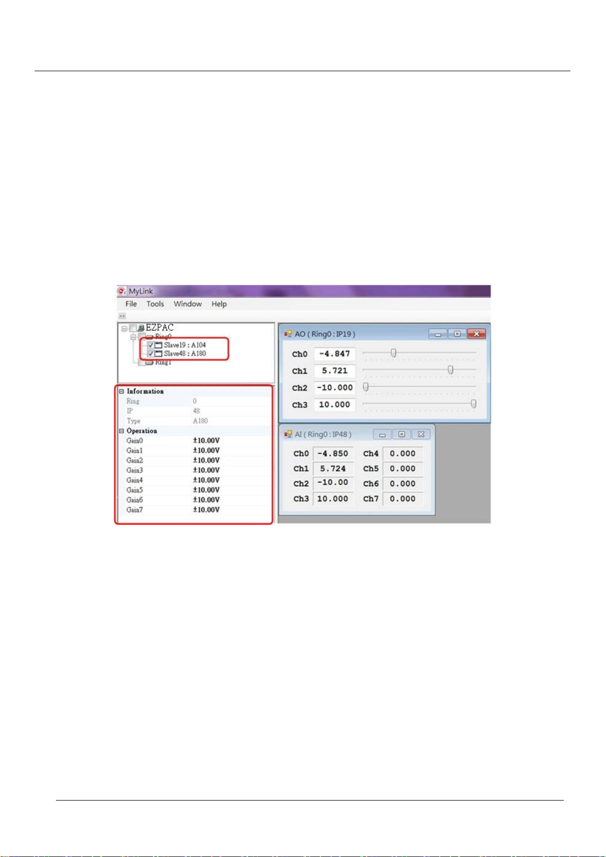
In this example, 4 AO (A104) channels are connected to the 4 AI (A180) channels. The remaining 4 channels
of AI connect to ground.
Figure 5-29: information of connected devices
Module Status
AO module with IP19 and AI module with IP48 are identified.
Property
The property of AO module is similar to DI O module. T he input range property can be set here. There are
8 channels with 4 ranges (±1.25/ ±2.50/ ±5.0/ ±10.0).
Operation
Move the track bar to change the output value of AO module and the value will also be shown in the AI
module.
5.2.4.2 108-A122
The only difference between 108-A122 and A104/A180 is 108-A122 has an EEPROM storage device. The
operation is almost the same as A104/A180 illustrated later.
Page 42
TPM
42
Figure 5-30: 108-A122 slave module
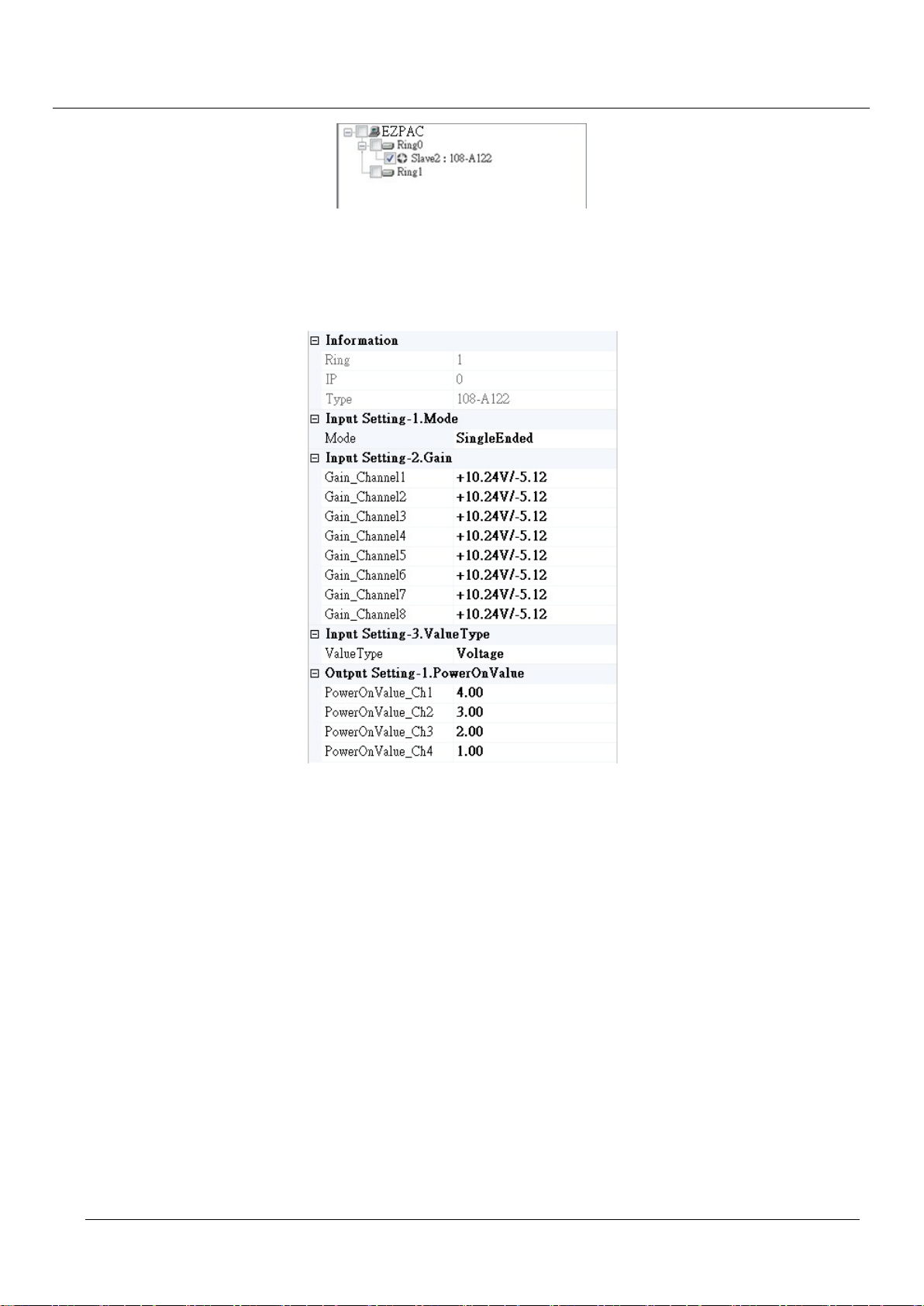
Module Status
The property sub-frame shows the information of 108-A122 with EEPROM.
EasyPAC User Manual
Figure 5-31: properties of 108-A122
Property
The extensions of 108-A122 are inputs – Mode, Gain and ValueType and output – PowerOnValue. All
parameter values could be stored in the EERPOM except the ValueType.
Mode: select the input mode single end or differential end.
Gain: select the input voltage range. It is separated into 8 grades - +/-80mV, +/-160mV, +/-320mV,
+/-640mV, +/-1.28V, +/-2.56V, +/-5.12V, +10.24/-5.12V. The input voltage larger than 5.12V is not
recommended.
ValueType: set the view of input/output as transformed voltage or the raw data. The rules to transform
to the voltage value by calling APIs are as following:
1. Take reference only on the positive voltage value. Take +10.24V for example, Range = 10.24 * 2,
Start = -10.24, the result could be obtained by calling API a122_get_input_value.
2. Input voltage Vin = (Value x Range) /65536 + Start
3. PowerOnValue: when the power supplies, the initial value of 108-A122. Default value is 0.
Page 43
TPM
43
EasyPAC User Manual
Operation
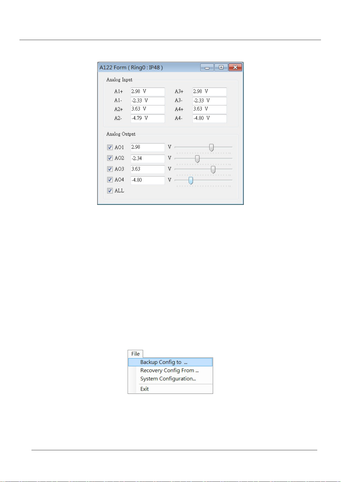
The demo program is cross-connection from 4 outputs to 8 inputs separately (ex. AO1 – A1+ – A3+)
Figure 5-32: screenshot of the example
The program keeps polling of the analog input data. There are only a few options users could change –
Input Setting-1.Mode (single end or differential), Input Setting-2.Gain (voltage) and the ValueType
(voltage output or raw data).
Users could change the output value by inputting the voltage value directly or by scrolling the slide bar.
Select the check box to choose which to output.
Retain Parameters
As mentioned above, 108-A122 is a module with an EEPROM for data storage and MyLink is a
parameter setting utility. It is very important to save the setting in the EEPROM so that users do not
have to set the parameters every time when system is brought up. Moreover, users who do not
thoroughly understand the settings could also use this module with the preset parameters.
Users could write the configuration in the EEPROM through File Backup Config to… as following
shown figure.
Figure 5-33: save parameters to EEPROM
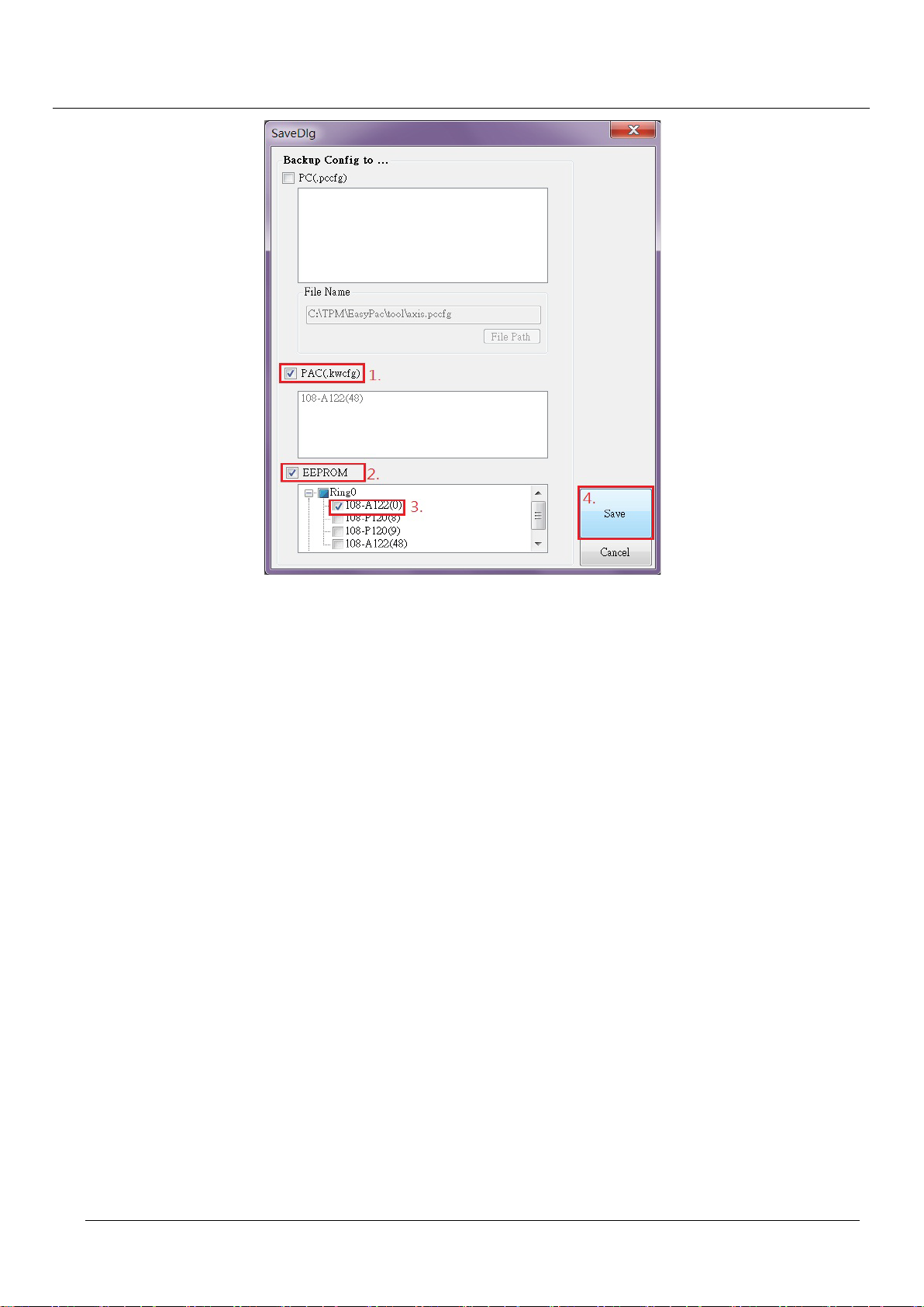
If the Backup Config to… option is hit, a new dialog will be popped up as figure below.
Page 44
TPM
44
EasyPAC User Manual
Figure 5-34: save configuration dialog
There are two targets of configuration storage – PAC and EEPROM
1. PAC
This option is saving the configuration as an AI.kwcfg file and then transferring to PAC for KW
use. It is not necessary to select devices from device list if the PAC checkbox is checked. Press the
“Save” button will finish the saving.
Note that the each AI IP address is supposed to be within 48 to 63. It will not be in the list if the IP
address is out of range.
2. EEPROM
Users need to take few steps to save the configuration in the EEPROM as following.
1. Check the EEPROM option, and all the modules with EEPROM will show up in the list.
2. Select modules need to store to EEPROM by checking the checkbox.
3. Press “Save” button.
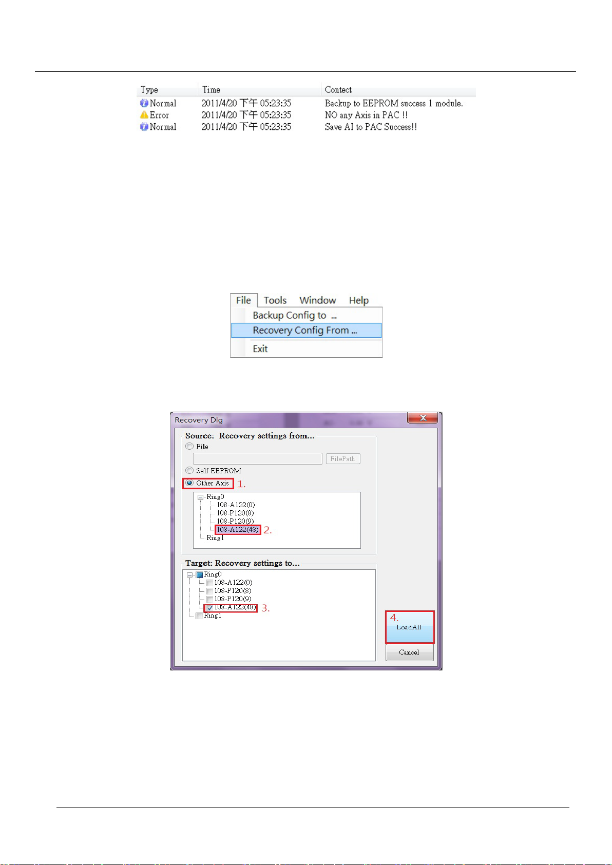
The status window displays the saving result with time stamps and messages.
Page 45
TPM
45
EasyPAC User Manual
Figure 5-35: saving status window
Duplication
This function is made to efficiently duplicate configuration profiles among same type of modules. For
example, users could duplicate the configuration profile to other 108-A122 from the settings of the
previous bought identical type product. The steps to duplicate are as following.
Select “File Recovery Config From…” from file option.
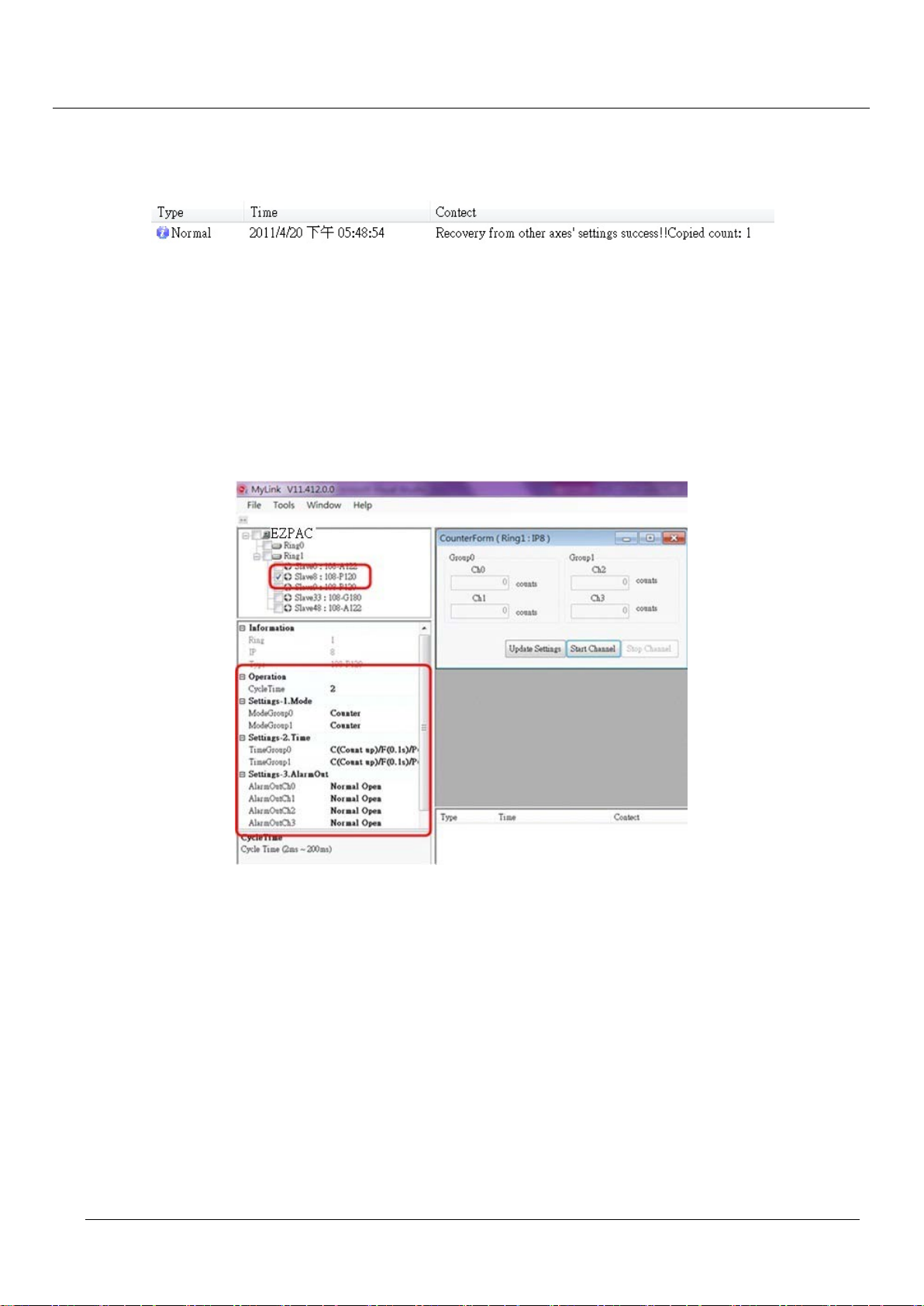
Figure 5-36: duplicate configura tion option
If the Recovery Config From… option is hit, a new dialog will be popped up as figure below.
Figure 5-37: recover profile dialog
Here is the duplicating sequence:
i. Select “Other Axis” from the radio button as the recovery source.
ii. Select the copy source from the module list.
iii. Select the destinations. Users could select multiple devices by multi-checking devices or
check the Ring to select all devices under the Ring.
Page 46
TPM
46
EasyPAC User Manual
iv. Press the “LoadAll” to finish the recovery.
The status window displays the recovery result with time stamps and messages.
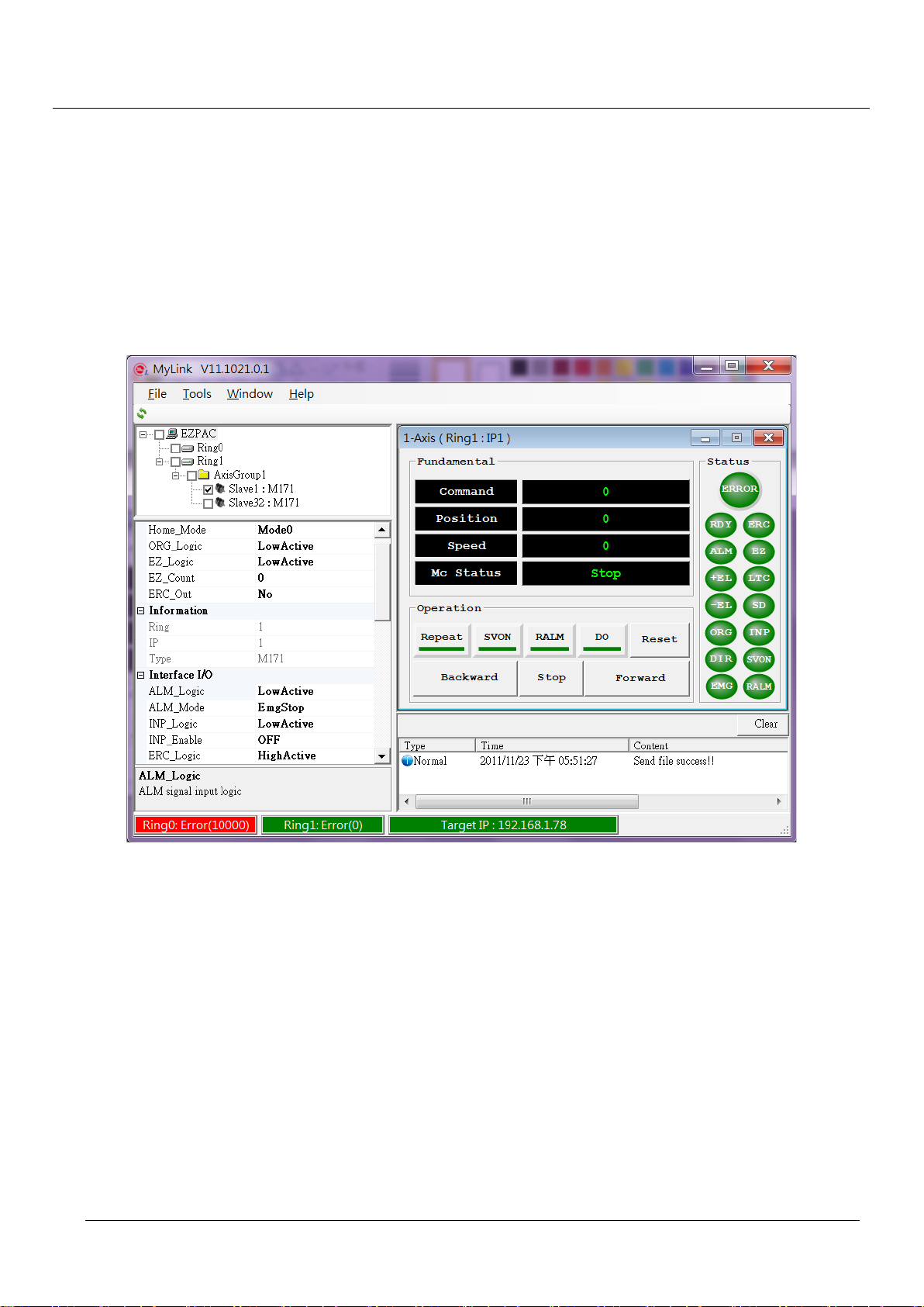
Figure 5-38: recovery status window
Note that the recovery is just recovering to the specified devices, not saving to EEPROM. If the profile
needs to be saved eternally, users still need to save it to the EERPOM.
5.2.5. PIO Counter Module Operation
The PIO counter module operation is illustration in this chapter. A signal generator is connected to channel 0
and channel 1 of a counter module.
Figure 5-39: MyLink control for counter module
Module Status
Displays counter modules found with corresponding IP address. The module name is a little bit
different with AI/O and DI/O. There are five modes of counter configurable. The frequency mode is
adapted hereafter.
Property
The 108-P120 extension properties include: Mode, Time, AlarmOut, Average, Edge, PowerOn,
SafeValue, UpperLimit and LowerLimit. Except the options of Mode and Time are set with Group as a
unity, other are set with each channel independently. IN0 and IN1 are grouped up as Group0 and IN2
and IN3 are grouped up as Group1.
The details of the properties are listed below:
Page 47

TPM
47
1. Cycle Time
It is the time period between two sampling times. The default value is 2ms and maximum at
200ms.
2. Mode
5 modes are available: Counter, Frequency, Period, GT and GC.
Mode name Parameter Description
– Counter mode
EasyPAC User Manual
Counter
Frequency
Time
0: up-count
1: down-count
Average Unused
Edge Trigger type: Rise/Fall
0 to 4,294,967,295
Upper Limit
Maximum number for up-count and initial number for down-count.
0 to 4,294,967,295.
Lower Limit
Initial number for up-count and minimum number for down-count.
Measured Value < Lower Limit or
AlarmOut
Measured value > Upper Limit
– Frequency mode
0.1s/1s/10s/100s the sampling period.
Time
1s: INx gets 1000 pulses within 1 second, the measured frequency
is 1KHz.
Average unused
Edge Trigger T ype: Rise/Fall
Period
Upper Limit Hz (0 ~ 4,294,967,295)
Lower Limit Hz (0 ~ 4,294,967,295)
Measured Value < Lower Limit or
AlarmOut
Measured value > Upper Limit
Period measurement mode, this is used to measure the ON-OFF
–
time of the incoming pulses, the max measured time is 800ms.
2ms/20m/200ms/800ms
Set the max measure time for INx input pulse.
Example: The period of INx input pulse is 1.5ms. The most
Time
accurate measure value can be obtained by 2ms. If the input pulse
period ranges from 1.5ms to 500ms, please use 800ms to measure
the period.
Calculate the value with different number for average. “2” means
Average
the period is averaged with 2 samples.
Edge Trigger type: Rise/Fall
Upper Limit ms (0 ~ 4,294,967,295)
Page 48

TPM
48
Mode name Parameter Description
Lower Limit ms (0 ~ 4,294,967,295)
AlarmOut When value < Lower Limit or value > Upper Limit
EasyPAC User Manual
GT
GC
–
Gate Time. To measure the Gate ON or OFF time with sampling
period 0.1ms.
Time Unused
Average Unused
Edge Trigger type: Rise/Fall
Upper Limit Sec (0 ~ 4,294,967,295)
Lower Limit Sec (0 ~ 4,294,967,295)
AlarmOut When value < Lower Limit or value > Upper Limit
Gate Counter is used to measure the number of pulses on the gate.
Example: The input pulse source is 1mm/pulse encoder. When the
measured gate count is 1000, the length is 1 meter. Only 2 channels
–
are available in this mode:
IN0: Count0 IN2: Count1
IN1: Gate0 IN3: Gate1
Time Unused
Average Unused
Edge Trigger type: Rise/Fall
Upper Limit (0 ~ 4,294,967,295)
Lower Limit (0 ~ 4,294,967,295)
AlarmOut When value < Lower Limit or value > Upper Limit
3. DO Output
AlarmOut: AlarmOut will be activated according to the set value as foregoing.
PowerOn Value: It is composed by 4 bits (0b0000). The power on state of DO can be set as ON or
OFF. If the value is 1, the output is ON when power on. If the value is 0, the
output is OFF when power on. The bit sequence from left to right are DO3,
DO2, DO1, DO0 correspondingly.
Safe Value: It is composed by 4 bits (0b0000). Safe value of DO can be set here. If the value
is 1, the output is ON when the safe protection is triggered. If the value is 0, the
output is OFF when the safe protection is triggered. The main purpose is to
protect from hardware damage when the module failure.
Operation
In this example, IN0 and IN1 are connected with a signal generator.
Set Mode to Frequency.
Set Time with default value.
Page 49
TPM
49
EasyPAC User Manual
Set Average to 1
Press StartChannel to get the measured value.
Note: please remember to save the set parameters to EEPROM in case the set parameters are gone after
reboot. Please go through AIO Module Operation subsection for reference.
5.2.6. Single Axis Module
Single Axis module is described in this section.
Figure 5-40: screenshot of single axis module
Module status
M171 module is identified and displayed in the above and is equipped with EEPROM. The functions of
motion slave modules without EEPROM will be limited: 1. No grouped axes motion; and 2.
SA_LoadConfigFile is needed to download parameter.
Property
There are 3 categories of setting: Homing mode, Driver I/O interface, Machine I/O interface. Please refer
to GA_GetSensor in this manual.
5.2.7. Grouped Axes
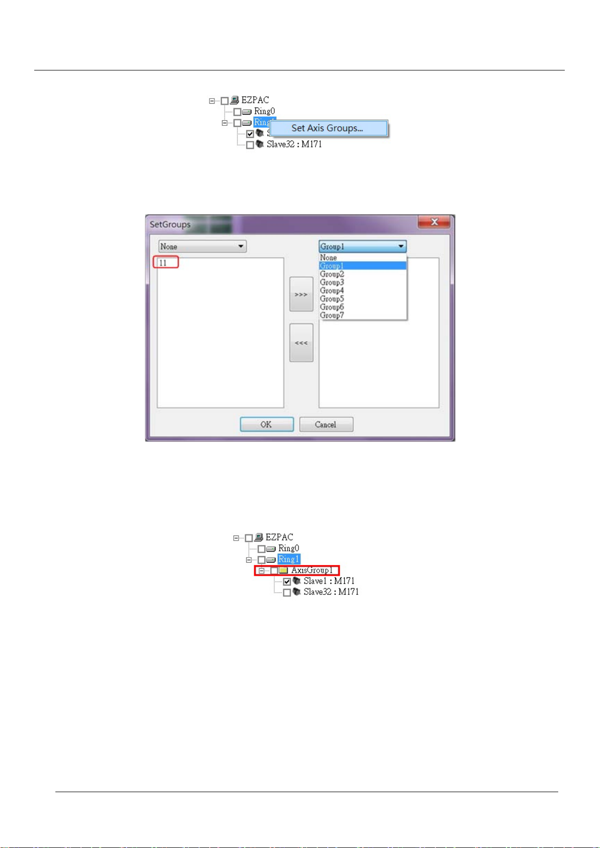
Multiple axes can be grouped up together by right click on the Ring and select “Set Axis Groups” as shown
Page 50
TPM
50
EasyPAC User Manual
below:
Figure 5-41: group up axes
When the “Set Axis Groups” option is clicked, a dialog will pop up as the following figure.
Figure 5-42: set group dialog
The “None” option of the left and right side means the axes have not joined groups. Select the non-grouped
axes with one of Group1~7 specified and press the arrow button “>>>” or “<<<” to make the selected axes
grouped up as a group. The grouped axes will show up in the device monitor as following:
Figure 5-43: grouped axes
In this example, M121 is a grouped axis under AxisGroup1 instead an independent axis.
Save And Recover Configurations
The reading and writing of configuration profile are almost the same as AI/O in the previous section
except one more place to save the configuration profile – pc.
Page 51
TPM
51
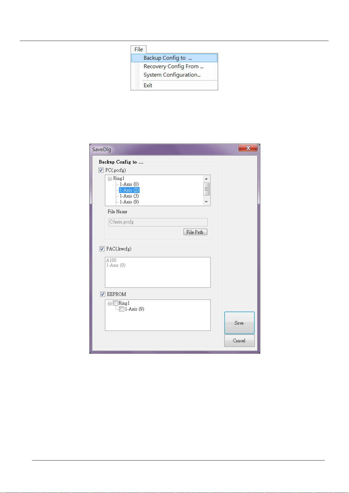
Figure 5-44: file options
Save
As mentioned above, a saving dialog will pop up if the “Backup Config to…” option is hit. There
are 3 options – PC, PAC and EEPROM
EasyPAC User Manual
Figure 5-45: the saving dialog for group axes
1. PC
Users could select the axes to be saved in the tree diagram. The “File Path” button let users
change storage path at will. Press “Save” to save the information including information,
interface I/O, pulse I/O and Operation in the PC.
2. PAC
If the PAC check box is checked, all the modules to be saved would be in the list without
selection needed. If an AI module is not in this list means the IP address is not within the
illegal range, 48~63. If the IP address of an axis module is not within the illegal range, 1~32
Page 52
TPM
52
would not be in the list. Modules within legal IP range will be saved as .kwcfg file in the
PAC.
3. EEPROM
Modules with EEPROM are in the list. Users could select modules need to save the profile in
the EEPROM and then press “Save” to save the configuration profile in the EEPROM.
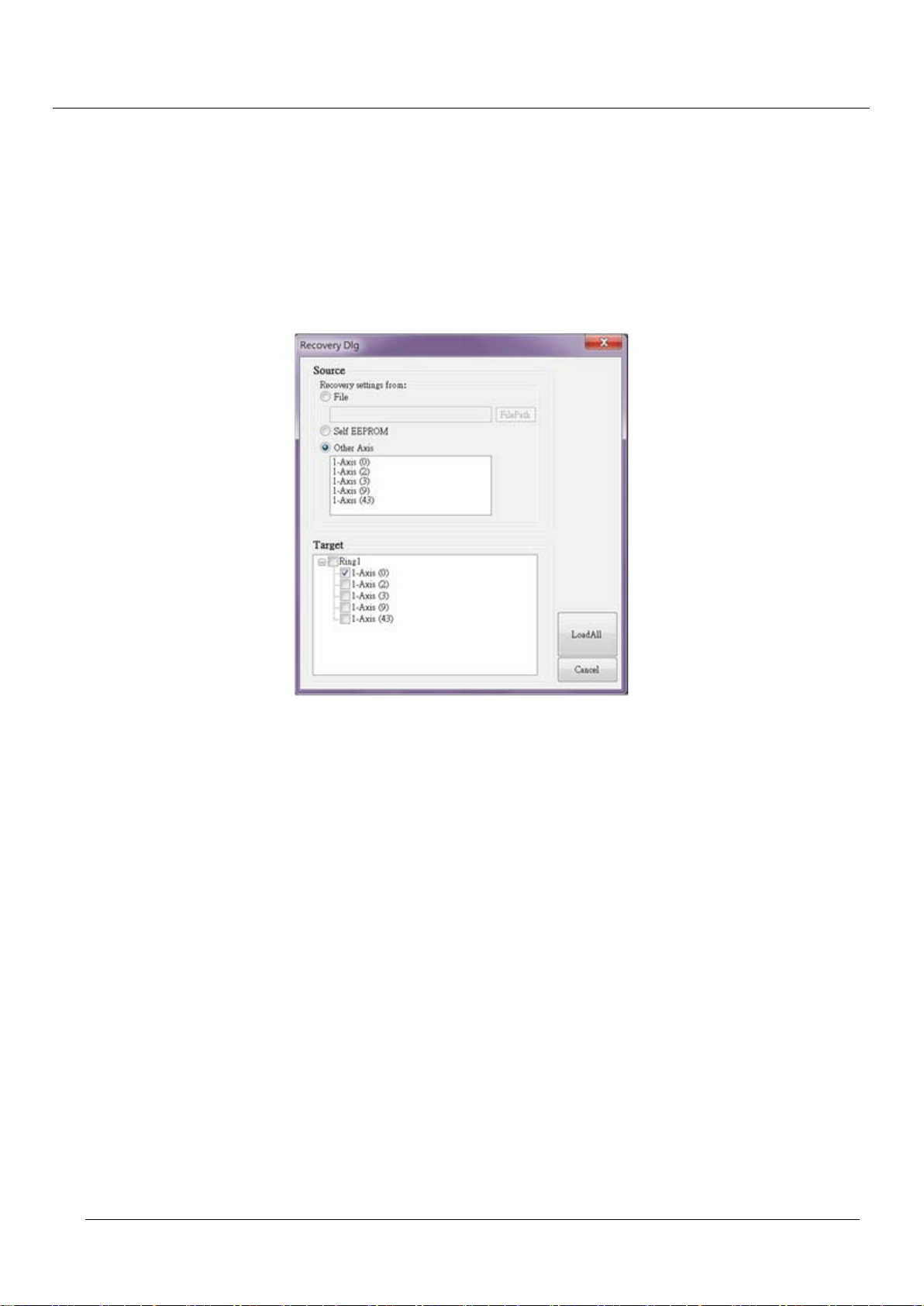
Recovery
The recovery dialog will show up if enters “File Recovery Config From…”.
EasyPAC User Manual
1. File
The recovery source could be stored as a file. Users could recover from the file to targets in
the target list.
2. Self EEPROM
Targets could be multi selected to be recovered from self EEPROM.
3. Other Axis
It is to duplicate the axis configuration profile from one source axis to the designated target
axes.
Press “LoadAll” to recover the configuration profile.
Figure 5-46: recovery dialog with file source
Page 53
TPM
53
EasyPAC User Manual
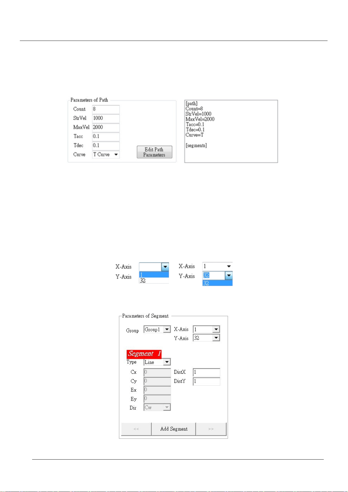
Edit Path File
Users could edit the interpolation motion path and save it as a .kwpts file under “Tool Edit Path”
option.
[Path]
Figure 5-47: screenshot of the editing interpolation motion path
This is the very first step to edit the motion path should be done before settings of the segments. Edit
the parameters and press the “Edith Path Parameters” button to update the file content at the right side.
The parameter will be described later.
[Segments]
Two axes say X and Y are supposed to be selected to form a segment. The X and Y need to be grouped
already. The corresponding IP of Y-axis will be removed if the X-axis has selected the one in advance.
Figure 5-48: picking IP of X and Y axis
Figure 5-49: parameters of a segment
Page 54
TPM
54
EasyPAC User Manual
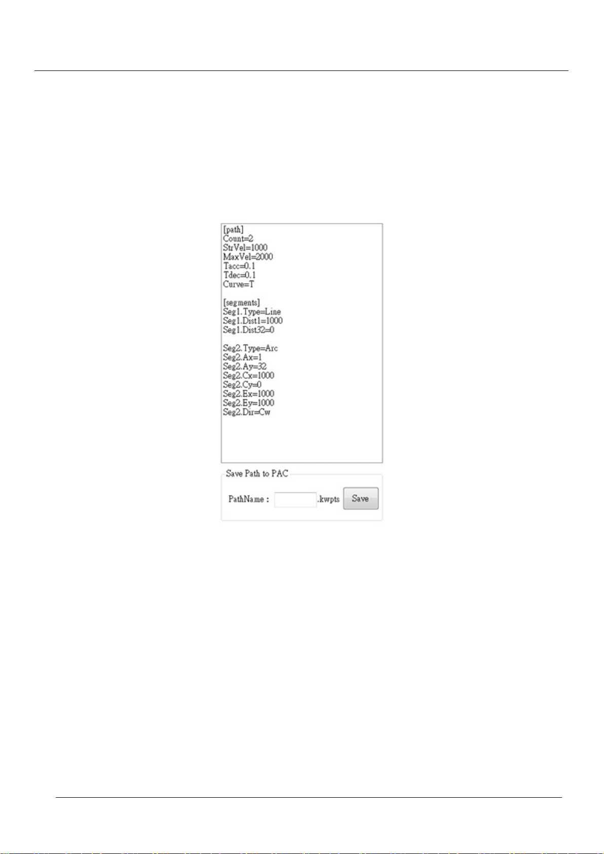
After setting of IP addresses of X and Y axis, users could edit the parameters of the segment. The first
parameter is “Type” with options “Line” and “Arc”. It needs DistX and DistY for type Line. With
respect to type Arc, it takes five parameters. Input all the necessary parameters then press “Add
Segment” to add the settings as a new se gment in the path file at ri ght hand side. Us ers could press “>>”
to start a new segment or press “<<” to modify the previous added segment.
If all the segments are finished, the “Save” button in the “Save Path to PAC” area will be enabled to
save the path to EasyPAC as shown below.
Figure 5-50: motion profile formed by segments
Here is an example that two axes form a round-angle rectangular with interpolation.
Page 55

TPM
55
Figure 5-51: motion path of two axes interpolation
[Path]
Count=8
StrVel=100
EasyPAC User Manual
MaxVel=6000
Tacc=0.1
Tdec=0.1
Curve: T
[Segments]
Seg1.Type=Line
Seg1.Dist8=0
Seg1.Dist9=1000
Seg2.Type=Arc
Seg2.Ax=8
Seg2.Ay=9
Seg2.Cx=1000
Seg2.Cy=0
Seg2.Ex=1000
Seg2.Ey=1000
Seg2.Dir=Cw
Seg3.Type=Line
Seg3.Dist8=2000
Seg3.Dist9=0
Seg4.Type=Arc
Page 56

TPM
56
Seg4.Ax=8
Seg4.Ay=9
Seg4.Cx=0
Seg4.Cy=-1000
Seg4.Ex=1000
Seg4.Ey=-1000
Seg4.Dir=Cw
Seg5.Type=Line
Seg5.Dist8=0
Seg5.Dist9=-1000
Seg6.Type=Arc
Seg6.Ax=8
Seg6.Ay=9
EasyPAC User Manual
Seg6.Cx=-1000
Seg6.Cy=0
Seg6.Ex=-1000
Seg6.Ey=-1000
Seg6.Dir=Cw
Seg7.Type=Line
Seg7.Dist8=-2000
Seg7.Dist9=0
Seg8.Type=Arc
Seg8.Ax=8
Seg8.Ay=9
Seg8.Cx=0
Seg8.Cy=1000
Seg8.Ex=-1000
Seg8.Ey=1000
Seg8.Dir=Cw
The path file stores each segment motion of each axis as a .kwpts file. Rules for motion path file editing
are listed below.
[Path]
Count = 8 No. of path segments, max. 100
StrVel = 100 Start velocity, unit is pps. Value is 0~6666666
Page 57

TPM
57
EasyPAC User Manual
MaxVel = 6000 Maximum velocity, unit is pps. Value is 0~6666666, must be > StrVel
Tacc = 0.1 Acc. time unit is sec, data type is float
Tdec = 0.1 Dec. time unit is sec, data type is float
Curve: T Velocity profile is T curve or S curve
Segment description: Start Point is (0, 1000)
Seg1.Type = Line Path type is line
Seg1.Dist8 = 0 Axis with IP8 is grouped, 0 pulses. Range: Dist1~Dist32
Seg1.Dist9 = 1000 Axis with IP9 is grouped, 1000 pulses. Range: Dist1~Dist32
Seg2.Type = Arc Path type is circle
Seg2.Ax = 8 Axis with IP8 is assigned as X-Axis. Range: 1~32
Seg2.Ay = 9 Axis with IP9 is assigned as Y-Axis. Range: 1~32
Seg2.Cx = 1000 Center of circle is 1000 relative to X-Axis.
Range: -134217728 ~ 134217727
Seg2.Cy = 0 Center of circle is 0 relative to Y-Axis.
Range: -134217728 ~ 134217727
Seg2.Ex = 1000 End point in X-Axis is 1000. Range: -134217728 ~ 134217727
Seg2.Ey = 1000 End point in Y-Axis is 1000. Range: -134217728 ~ 134217727
Seg2.Dir = Cw Clockwise circle
Seg3.Type = Line Path type is line
Seg3.Dist8 = 2000 Axis with IP8 is grouped, 2000 pulses. Range: Dist1~Dist32
Seg3.Dist9 = 0 Axis with IP9 is grouped, 0 pulses. Range: Dist1~Dist32
Seg4.Type = Arc Path type is circle
Seg4.Ax = 8 Axis with IP8 is assigned as X-Axis. Range: 1~32
Seg4.Ay = 9 Axis with IP9 is assigned as Y-Axis. Range: 1~32
Seg4.Cx = 0 Center of circle is 0 relative to X-Axis.
Range: -134217728 ~ 134217727
Seg4.Cy = -1000 Center of circle is 1000 relative to Y-Axis.
Range: -134217728 ~ 134217727
Seg4.Ex = 1000 End point in X-Axis is 1000. Range: -134217728 ~ 134217727
Seg4.Ey = -1000 End point in Y-Axis is 1000. Range: -134217728 ~ 134217727
Seg4.Dir = Cw Clockwise circle
The sequence of Seg5 ~ Seg8 are similar to which of Seg1 ~ Seg4 which are skipped here.
Operation
Page 58
TPM
58
EasyPAC User Manual
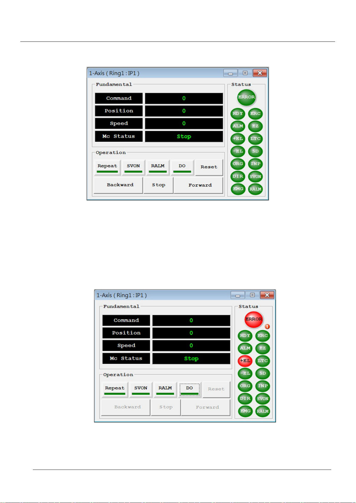
All the signals are displayed in green background after the hardware properties are set. The single axis
motion window is shown in the following figure.
Figure 5-52: screenshot of axis control window
Before testing the axis, it is necessary to make the motor servo on. The “SVON” signal will become from
green to red. If the “Servo Drive Alarm Reset” is connected to the output signal, the “RALM” must be
pressed and the corresponding signal turns red. If the “Repeat” option is checked, the motion will go back
and forth infinitely with the pre-defined position. The “DIR” signal will toggle as well.
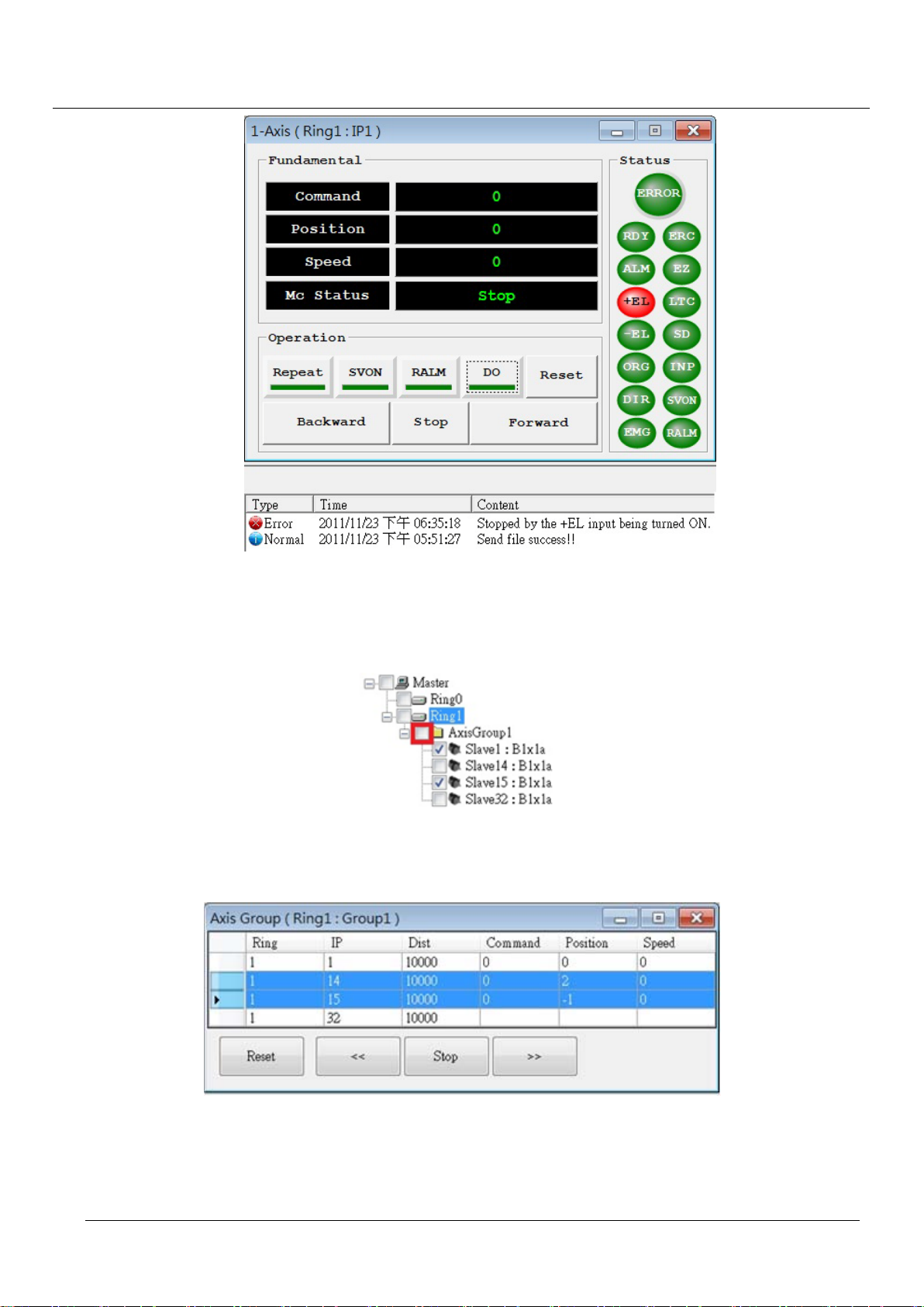
If there are errors terminate the motion, the “Error” light would be on and press the exclamation mark will
pop the error message as shown below.
Figure 5-53: motion in error status
After the exclamation mark being pressed, the system will restore from error to normal and display the error
messages in the message window as shown below.
Page 59
TPM
59
EasyPAC User Manual
Figure 5-54: restore from error state
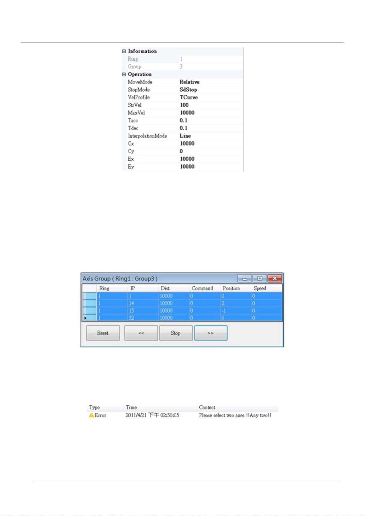
With respect to the group axes, the “SVON” action should be done as mentioned. Users could check the
group folder to bring up the axis group option.
Figure 5-55: check the group folder to update axis parameters
The window of grouped axes properties is as the following figure.
Figure 5-56: axis group properties
Before running the axis, please make sure the properties are set correctly.
Page 60
TPM
60
Figure 5-57: axis properties window
MoveMode: the options are Relative or Absolute move.
StopMode: the options are abrupt stop or slow down stop
EasyPAC User Manual
VelProfile: the options are T-curve or S-curve
InterpolationMode: the options are Line or Arc
The group operation depends on the VelProfile (Line/Arc). More than two axes could be joined together as a
group in line interpolation mode.
Figure 5-58: more than two axes are possible to run together in line interpolation mode
Users could only choose exactly two axes to do arc interpolating motions. More than two or less than two
axes will cause an error message in the message window.
Figure 5-59: error message if not two axes are doing arc interpolating motion
Page 61
TPM
61
EasyPAC User Manual
5.3. MyDataCheck
EasyPAC provides 2 kinds of data type for MULTIPROG and Modbus:
1. The data type defined by I/O Configuration on ProConOS is to be used for MULTIPROG.
2. The data type defined by Modbus is to be used for HMI connection.
MyDataCheck is used to map easily and correctly the data in ProConOS to MULTIPROG and Modbus.
MyDataCheck is installed in the remote PC but the EasyPAC.
Recommended Hardware Requirement
PC Hardware: PC or laptop with Intel Centrino up CPU
Memory: 1GB RAM
OS: Windows 2000/XP/Win7
LAN card: RJ-45 10/100/1000 Mbps
Software Installation
1 executable file: MyDataCheck.exe
ProConOS/MULTIPROG I/O Configuration
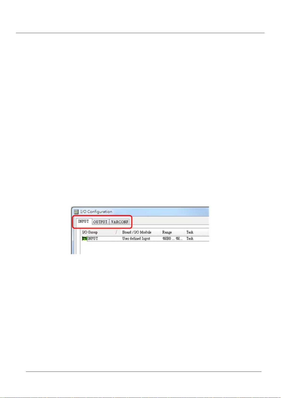
There are 3 types of memory: INPUT (%I), OUTPUT (%Q), VARCONF (%M).
Figure 5-60: three tabs of each type of memory
Ring_0 of EasyPAC supports up to 48 DIO modules and 16 (IP48~IP63) AIO or PIO modules.
INPUT/OUTPUT is explained in the following:
Total length of INPUT:
Local DI (1) + Motionnet DI (IP0~IP47) + Motionnet AI (IP48~IP63)
= 1 + 48 (IP) x 4 (Port) x 1 (Byte) + 16 (IP) x 8 (Channel) x 2 (Byte)
= 1 + 192 + 256
= 449 (Byte)
Total length of OUTPUT:
Local DO (1) + Motionnet DO (IP0~IP47) + Motionnet AO (IP48~IP63)
Page 62

TPM
62
= 1 + 48 (IP) x 4 (Port) x 1 (Byte) + 16 (IP) x 8 (Channel) x 2 (Byte)
= 1 + 192 + 256
= 449 (Byte)
EasyPAC User Manual
Page 63

TPM
63
The reference table is shown below.
Type Length (Byte)
EasyPAC User Manual
INPUT (%I)
OUTPUT (%Q)
VARCONF (%M)
Non Retain
0 ~ 448
Non Retain
0 ~ 448
Non Retain
0 ~ 47999
Retain
10000000 ~ 10013311
Local DI
Motionnet DI 192
449
1
Motionnet AI 256
Local DO
Motionnet DO 192
449
1
Motionnet AO 256
MB (Coil)
1024
MB (Holding Register) 1024
MB (Discrete Input) 1024
MB (Input Register) 1024
48000
User Define 35904
Motion (Single) 5000
Motion (Multiple) 1000
Gateway 2000
User Define 13312 13312
Table 5-1: data type with memory occupation table
Real variable (%I, %Q)
%IX: Bit Input, %IX 1.2 means bit 2 of byte 1.
%IQ: Bit Output, %QX 2.3 means bit 3 of bye 2.
%IB: Byte input, %IB 1 means byte 1.
%QB: Byte output, %QB 2 means byte 2.
Local 8DI/8DO is mapped to port 0 and can be accessed by %IB 0 (%IX 0.0 ~ %IX 0.7) and %QB 0 (%QX
0.0~%QX 0.7).
Each Motionnet DIO slave module has 4 ports (0~3) and each port is 8-bit.
%IW: Word input. This is used to get AI value by channel.
%QW: Word output. This is used to set AO value by channel.
The maximum channel number of Motionnet AIO slave module is 8 (0~7).
%ID: Double Word Input. This is used to get counter value by channel.
The maximum channel number of Motionnet counter module is 4 (0~3).
Page 64

TPM
64
VARCONF
Virtual variable (%M)
%MX: used for BOOL type
%MB: used for BYTE type
%MW: used for WORD type
%MD: used for DWORD type
The following 8 non-retain data types are designed for Modbus:
MB (Coil): is mapped to Tag for Modbus.
MB (Holding Register): is mapped to Output for Modbus.
MB (Discrete Input): is mapped to Input Tag for Modbus.
MB (Input Register): is mapped to Input for Modbus.
User Define: is defined by user.
Motion (Single): Single Axis Data.
Motion(Multiple): Multiple Axis Data.
EasyPAC User Manual
Gateway: to be implemented.
Retain Memory is ranged from %MB 3.10000000 to %MB 3.10013311 (i.e. 13312 Bytes).
MULTIPROG Memory Address
Type
Begin Access Tag End Access Tag
Local DI %IB 0 %IX 0.0 %IB 0 %IX 0.7
Motionnet DI %IB 1 %IX 1.0 %IB 192 %IX 192.7
Motionnet AI %IB 193 %IW 193 %IB 448 %IW 447
Local DO %QB 0 %QX 0.0 %QB 0 %QX 0.7
Motionnet DO %QB 1 %QX 1.0 %QB 192 %QX 192.7
Motionnet AO %QB 193 %QW 193 %QB 448 %QW 447
MB (Coil) %MB 3.0 %MB 3.1023
MB (Holding Register) %MB 3.1024 %MB 3.2047
MB (Discrete Input) %MB 3.2048 %MB 3.3071
MB (Input Register) %MB 3.3072 %MB 3.4095
User Define %MB 3.4096 %MB 3.39999
Motion (Single) %MB 3.40000 %MB 3.44999
Motion (Multiple) %MB 3.45000 %MB 3.45999
Gateway %MB 3.46000 %MB 3.47999
User Define %MB 3.10000000 %MB 3.10013311
Table 5-2: MULTIPROG memory table
Page 65

TPM
65
EasyPAC User Manual
To support connection with HMI by Modbus the following memory design is implemented
Modbus Memory
Modbus Memory is grouped into the following 4 sections:
Coil: Output Tag (Bit)
Real I/O: ranged from 0 to 1543 (BOOL)
Virtual: ranged from 1544 to 9735 (BOOL)
Holding Register: Output Data (Word)
Real I/O: ranged from0 to 127 (WORD)
Virtual: ranged from 128 to 639 (WORD)
Discrete Input: Input Tag (Bit)
Real I/O: ranged from 0 to 1543 (BOOL)
Virtual: ranged from 1544 to 9735 (BOOL)
Input Register: Input Data (Word)
Real I/O: ranged from 0 to 127 (WORD)
Virtual: ranged from 128 to 639 (WORD)
Please refer to the following summary table.
Type
Begin End
Local DI 0 (BOOL) 7 (BOOL)
Motionnet DI 8 (BOOL) 1543 (BOOL)
Motionnet AI 0 (WORD) 127 (WORD)
Local DO 0 (BOOL) 7 (BOOL)
Motionnet DO 8 (BOOL) 1543 (BOOL)
Motionnet AO 0 (WORD) 127 (WORD)
MB(Coil) 1544 (BOOL) 9735 (BOOL)
MB(Holding Register) 128 (WORD) 639 (WORD)
MB(Discrete Input) 1544 (BOOL) 9735 (BOOL)
MB(Input Register) 128 (WORD) 639 (WORD)
User Define
Motion(Single)
Modbus Memory Address
Motion(Multiple)
Gateway
User Define
Table 5-3: Modbus memory table
5.3.1. Data Address Mapping
MyDataCheck is designed for data transforming of Motionnet slave modules supported by EasyPAC.
Page 66

TPM
66
Figure 5-61: MyDataCheck icon a nd main window
Title: MyDataCheck V11.819.0.3 is the version information.
Virtual: is for virtual Memory Address mapping.
Ring_0: is for Motionnet DIO/AIO/PIO modules address mapping.
Ring_1: is for Motionnet Axis Module address mapping.
5.3.1.1 Ring_0 Memory Address Mapping
EasyPAC User Manual
Figure 5-62: Ring_0 memory address mapping
Module: Select the module model for Ring_0.
IP: slave module IP, IP0~IP47 is for DIO and IP48~IP63 is for AIO or PIO.
Mode: Select the Modbus type.
Page 67
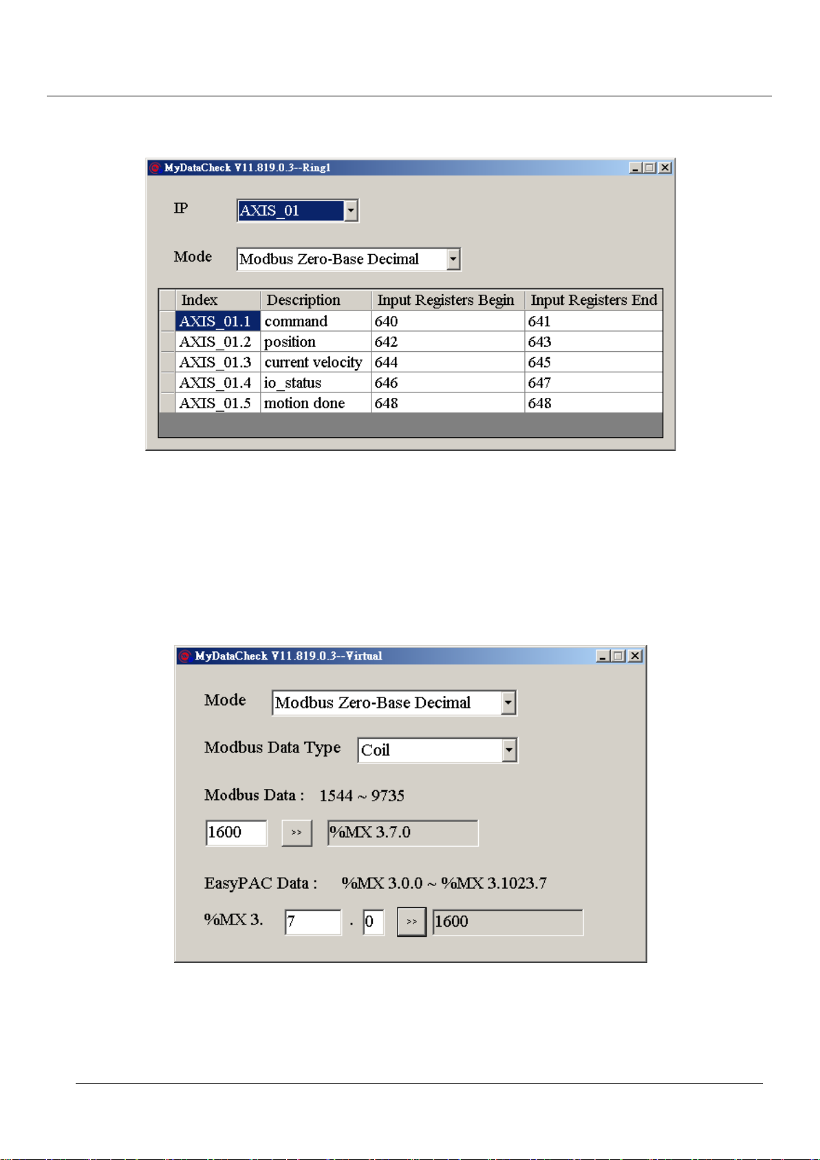
TPM
67
5.3.1.2 Ring_1 Memory Address Mapping
Figure 5-63: Ring_1 memory address mapping
EasyPAC User Manual
The available Axis module for Ring_1 is listed here.
IP: IP1~IP32 is for single axis module. IP1 = AXIS_01 and IP32 = AXIS_32.
Mode: Select the Modbus type.
5.3.1.3 Virtual Memory Address Mapping
Figure 5-64: virtual memory address mapping
Mode: Select the Modbus type.
Modbus Data Ty pe: Coil (Output Tag), Discrete In put (Input Tag), Holding Register (Output Data) or Input
Register (Input Data).
Page 68

TPM
68
Modbus Data: Modbus data is mapped to %M of MULTIPROG.
EasyPAC Data: %M of MULTIPROG is mapped to Modbus data.
5.3.2. Address Mapping Table
Data type of Modbus is in the following table.
Primary tables Object type Type of
Discrete Input Single bit Read-Only
Coils Single bit Read-Write
Input Registers 16-bit word Read-Only
Holding Registers 16-bit word Read-Write
Table 5-4: data type of Modbus
Ring_0 DI/O
DI MODBUS DO MODBUS
EasyPAC User Manual
IP
%I
L %IB 0 0 0 7 7 %QB 0 0 0 7 7
%IB 1 8 8 15 F %QB 1 8 8 15 F
%IB 2 16 10 23 17 %QB 2 16 10 23 17
0
%IB 3 24 18 31 1F %QB 3 24 18 31 1F
%IB 4 32 20 39 27 %QB 4 32 20 39 27
Discrete Input
Begin End Begin End
DEC HEX DEC HEX DEC HEX DEC HEX
Table 5-5: table of Ring_0 DI/O
%Q
Coil
IP: “L” represents Local DI (%IB 0) and Local DO (%QB 0).
“0” is the slave module with IP 0. Available IP ranges from 0~47.
The following data type is available with same slave IP: 32DI (IB1~4), 32DO (QB1~4) or 16DI/16DO
(IB1~2/QB1~2).
Page 69

TPM
69
Ring_0 AI/O and Counter
AI COUNTER MODBUS AO MODBUS
EasyPAC User Manual
IP
%I
%IW 193 %ID 193 0 0 %QW 193 0 0
%IW 195 1 1 %QW 195 1 1
%IW 197 %ID 197 2 2 %QW 197 2 2
%IW 199 3 3 %QW 199 3 3
48
%IW 201 %ID 201 4 4 %QW 201 4 4
%IW 203 5 5 %QW 203 5 5
%IW 205 %ID 205 6 6 %QW 205 6 6
%IW 207 7 7 %QW 207 7 7
Table 5-6: table of R ing_0 AI/O and counter
Input Registers
%Q
DEC HEX DEC HEX
Holding Registers
IP: “48” Available IP for AIO/PIO is ranged from 48 to 63 and the total number is 16.
The following data types are available with the same slave IP: 8 Channel AI (%IW 193 ~ 207), 8 Ch. AO
(%QB 193 ~ 207) and 4 Channel PI Counter (%ID 193 ~ 205).
The data type of AIO is WORD (Hex 0x0000~0xFFFF). The engineering unit can be calculated. When the
gain of Ch.0 of AI is ±10V, %IW 193 = 0x0000 (-10V) ~ 0xFFFF (+10V)
The data type of PIO counter module is DWORD (Hex 0x00000000~0xFFFFFFFF).
In the case of 108-P120, different modes can be set as described in the following:
1. Counter: Count the no. of pulses.
2. Frequency: Measure the frequency of the input pulse (Time is 0.1s~100s).
For example, When Time is set to 1s and gets 1000 pulse from IN0, %ID 193 = 0x000003E8. The freq. is
1 KHz.
3. Period: Measure the period of the incoming pulse in the unit of ns.
For example, when the input pulse is with 2ms width in IN0, %ID 193 = 0x001E8480, period is
2000000ns. The freq. is 500 Hz.
4. GT: Measure the ON/Off Time in the Gate, sampling period is 0.1ms.
For example, the signal in the gate is 2 seconds, 2000ms/0.1ms= 20000, %ID 193 = 0x00004E20.
5. GC: Only 2 channels are available in this mode:
Channel 0 Channel 1
IN0: Count0 IN2: Count1
IN1: Gate0 IN3: Gate1
IN1 and IN3: Measure the Gate input time
IN0 and IN2: Measure the pulse input Count
Page 70

TPM
70
Ring_1 Axis
AXES MODBUS
EasyPAC User Manual
IP
Input Registers
Begin End
DEC HEX DEC HEX
AXIS_01.1 Command 640 280 641 281
AXIS_01.2 Position 642 282 643 283
1
AXIS_01.3 current velocity 644 284 645 285
AXIS_01.4 io_status 646 286 647 287
AXIS_01.5 motion done 648 288 648 288
Table 5-7: table of Ring_1 axis
IP: “1” The available IP for Axis module is 1 ~32 (Total no. is 32).
IP1 is for Axis_01
AXIS_01.1 command: DWORD
Command Position: 0x00000000~0xFFFFFFFF (Pulse).
AXIS_01.2 position: DWORD
Current Position: 0x00000000~0xFFFFFFFF (Pulse).
AXIS_01.3 current velocity: DWORD
Current velocity: 0x00000000~0xFFFFFFFF (PPS).
AXIS_01.4 io_status: DWORD
I/O status of the axis: “1” is ON, “0” is OFF, Bit16 ~ Bit31 is reserved.
Bit0 (RDY): RDY pin input
Bit1 (ALM): Alarm Signal
Bit2 (+EL): Positive Limit Switch
Bit3 (-EL): Negative Limit Switch
Bit4 (ORG): Origin Switch
Bit5 (DIR): DIR output
Bit6 (EMG): Emergency signal input
Bit7 (PCS): PCS signal input
Bit8 (ERC): ERC pin output
Bit9 (EZ): Index signal
Bit10 (CLR): Clear Counter Input
Bit11 (Latch): Latch signal input
Bit12 (SD): Slow Down signal input
Bit13 (INP): In-Position signal input
Bit14 (SVON): Servo-ON output status
Bit15 (RALM): Alarm Reset output status
Page 71

TPM
71
AXIS_01.5 motion done: WORD
Motion done is the axis status, WORD, value is 0x0000~0x000B, 0x000C ~ 0xFFFF is reserved.
0x0000: Stop
0x0001: Wait STA
0x0002: Wait ERC finish
0x0003: Wait Dir change
0x0004: BackLashing
0x0005: Wait PA/PB
0x0006: In FA motion
0x0007: In FL motion
0x0008: Acc
0x0009: In FH motion
0x000A: Dec.
0x000B: Wait INP
EasyPAC User Manual
Virtual Data
Digital output:
%M
%M
Begin End
B 3. X 3.
0 0 0 0 7 1544 608 1551 60F
Table 5-8: digital output of virtual data
Digital Output is described in the following:
%MB 3.0 = Coil 1544 ~ Coil 1551
%MX 3.0.0 = Coil 1544
%MX 3.0.1 = Coil 1545
%MX 3.0.2 = Coil 1546
%MX 3.0.3 = Coil 1547
%MX 3.0.4 = Coil 1548
MODBUS
Coil
Begin End
DEC HEX DEC HEX
%MX 3.0.5 = Coil 1549
%MX 3.0.6 = Coil 1550
%MX 3.0.7 = Coil 1551
Page 72

TPM
72
Digital input:
EasyPAC User Manual
%M
%M
Begin End
DEC HEX DEC HEX
B 3. X 3.
2048 2048 0 2048 7 1544 608 1551 60F
Table 5-9: digital input of virtual data
Digital Input is described in the following
%MB 3.2048 = Discrete Input 1544 ~ Dis crete Input 1551
%MX 3.2048.0 = Discrete Input 1544
%MX 3.2048.1 = Discrete Input 1545
%MX 3.2048.2 = Discrete Input 1546
%MX 3.2048.3 = Discrete Input 1547
%MX 3.2048.4 = Discrete Input 1548
%MX 3.2048.5 = Discrete Input 1549
%MX 3.2048.6 = Discrete Input 1550
MODBUS
Discrete Input
Begin End
%MX 3.2048.7 = Discrete Input 1551
Register:
MODBUS
Holding
%M
Registers
MODBUS
Input
%M
Registers
DEC HEX DEC HEX
W 3. W 3.
1024 128 80 3072 128 80
Table 5-10: register of virtual data
Virtual data is described in the following:
%MW 3.1024 = Holding Registers 128
%MW 3.3072 = Input Registers 128
5.3.3. Making Memory Add ress Table from System File
By using the function of MyLink, the system configuration file could easily be generated. It is a time ef f icient
approach to make the memory address table by importing the MyLink generated config file. The imported
memory address table is illustrated as the following table.
Page 73
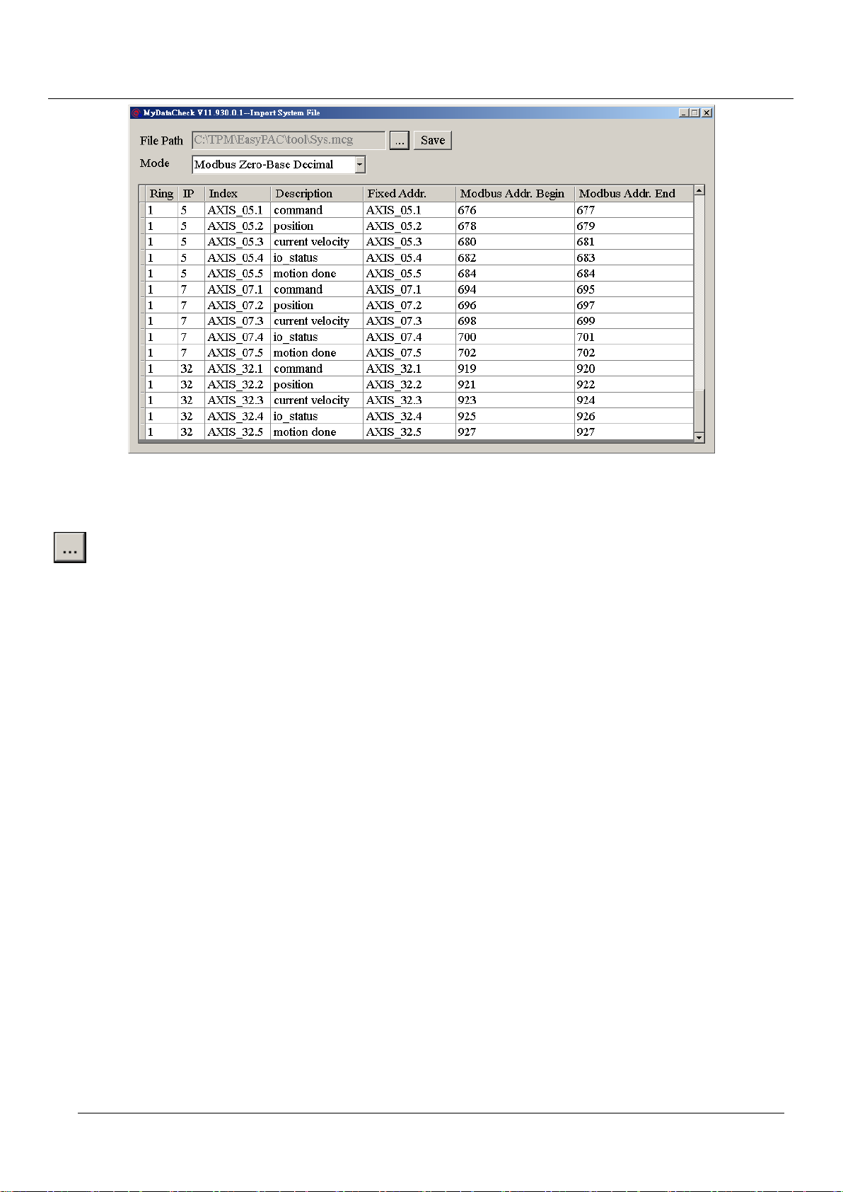
TPM
73
Figure 5-65: generated memory address table by .mcg file
EasyPAC User Manual
Relative functions are listed.
: Select the system file generated by MyLink.
Save: Save the result in text format which is readable and editable by Excel.
Mode: Select the Modbus data format.
5.3.4. Mapping Tables
Page 74
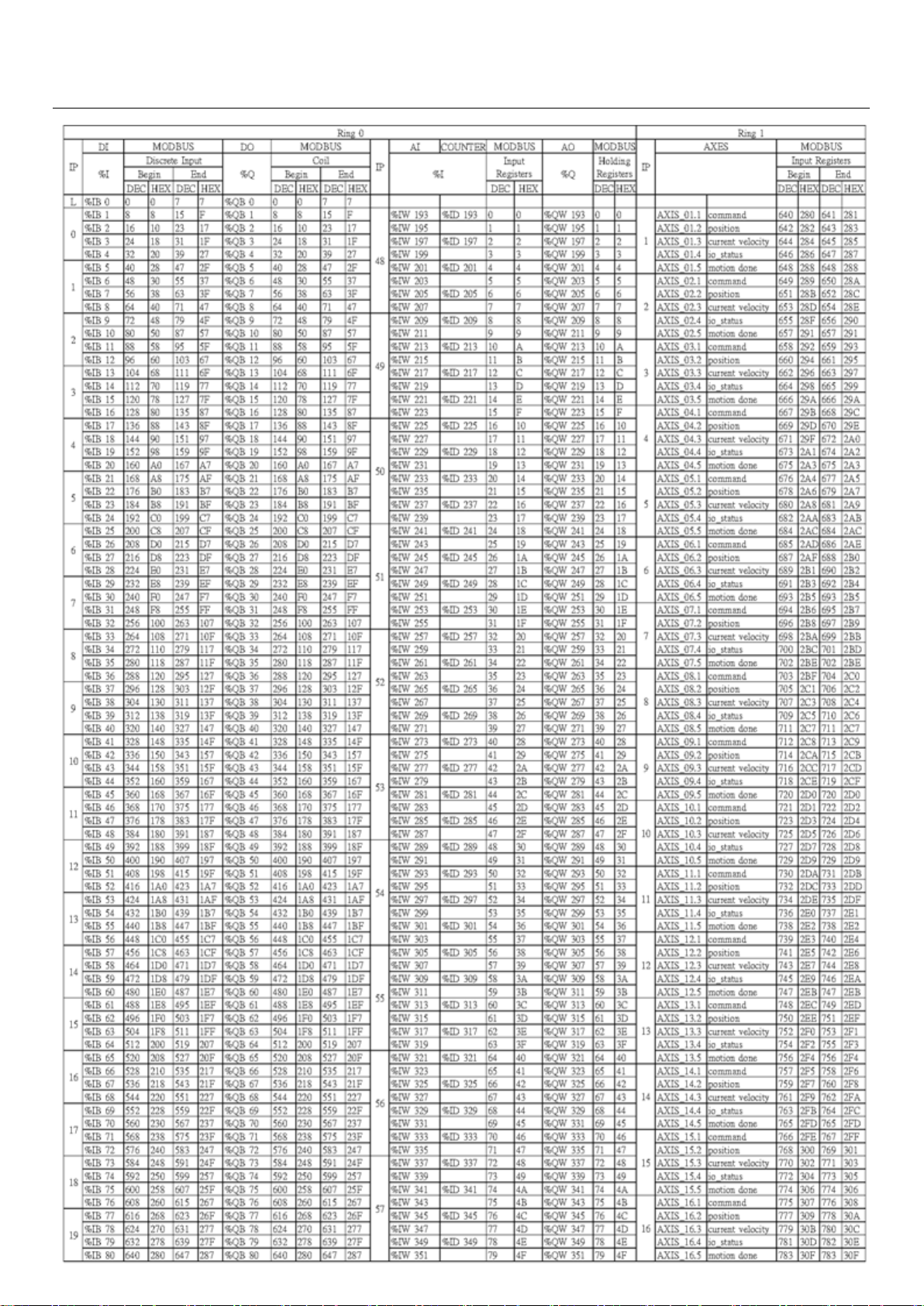
TPM
74
EasyPAC User Manual
Page 75
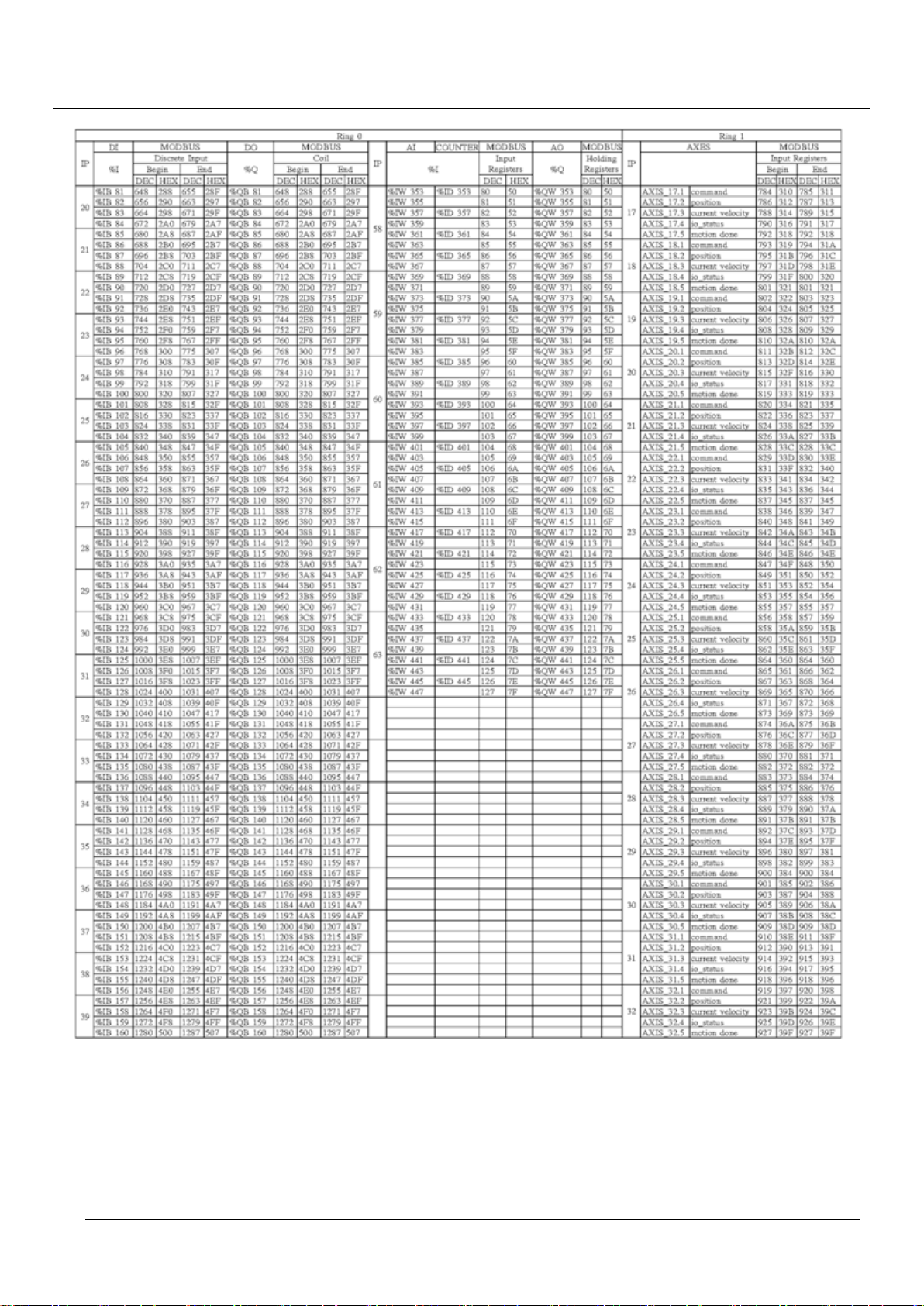
TPM
75
EasyPAC User Manual
Page 76
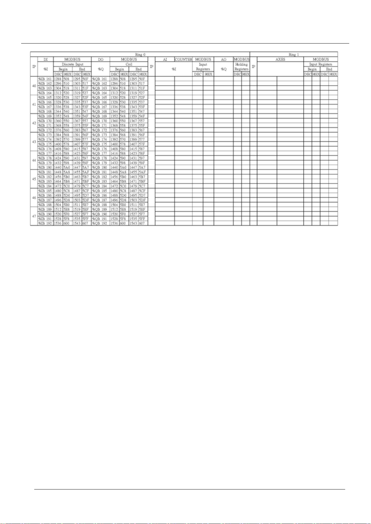
TPM
76
EasyPAC User Manual
Page 77
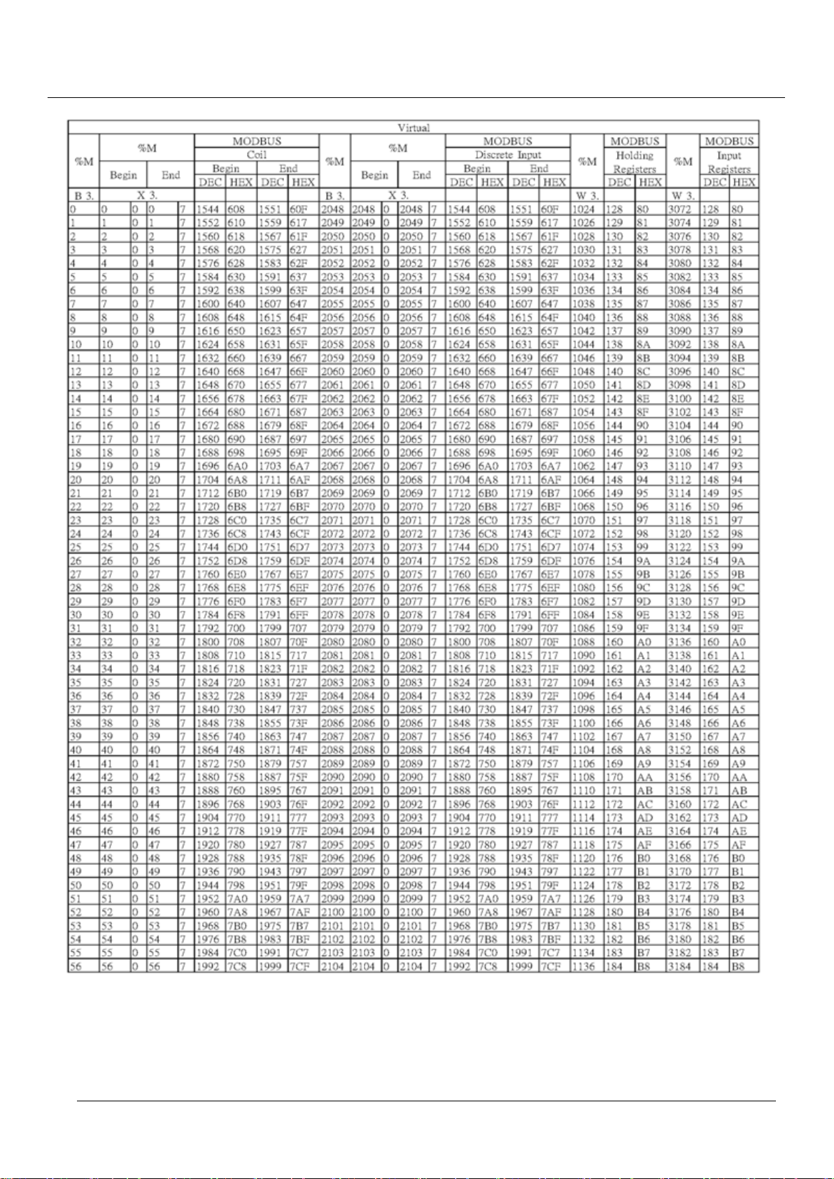
TPM
77
EasyPAC User Manual
Page 78
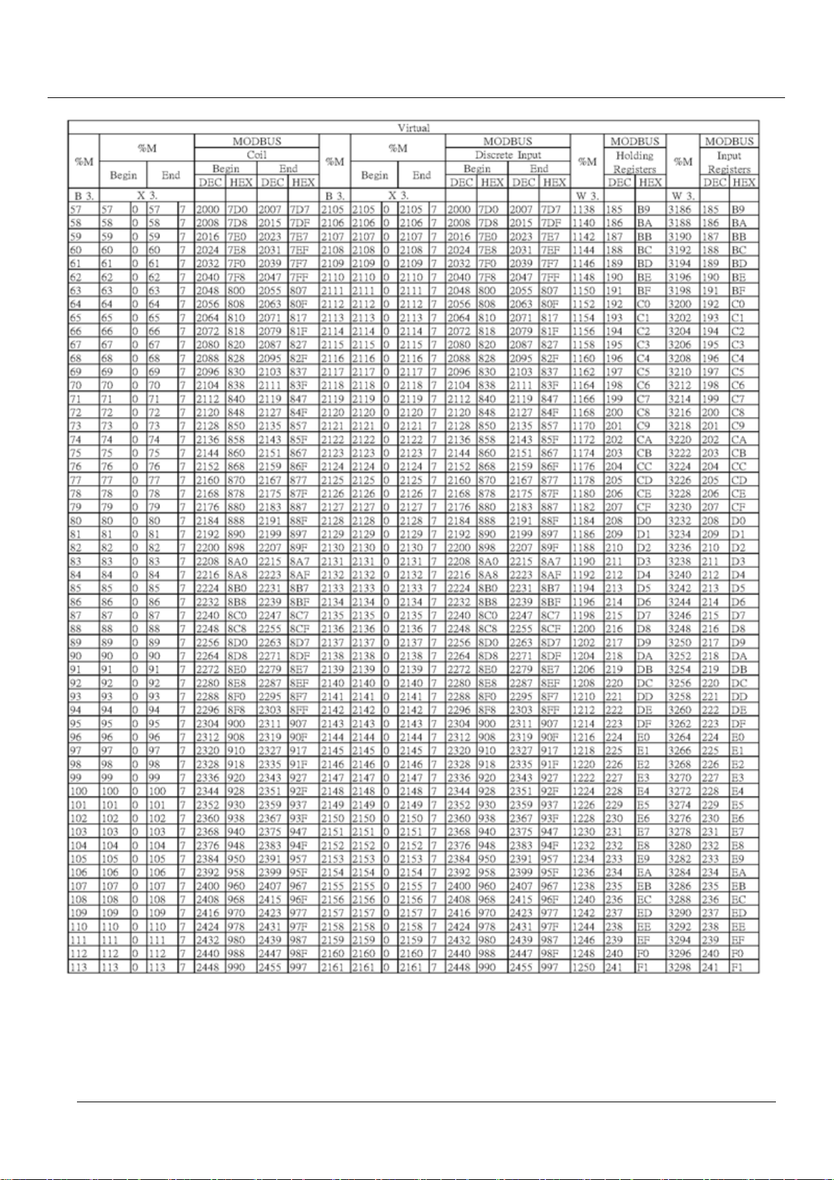
TPM
78
EasyPAC User Manual
Page 79
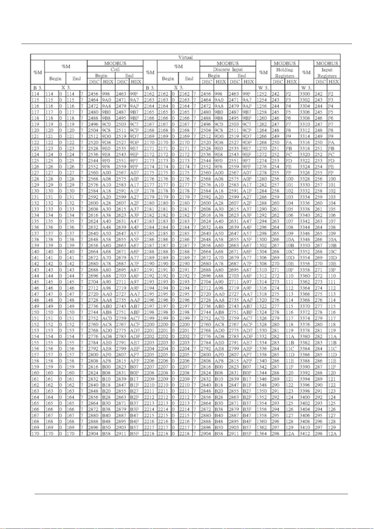
TPM
79
EasyPAC User Manual
Page 80
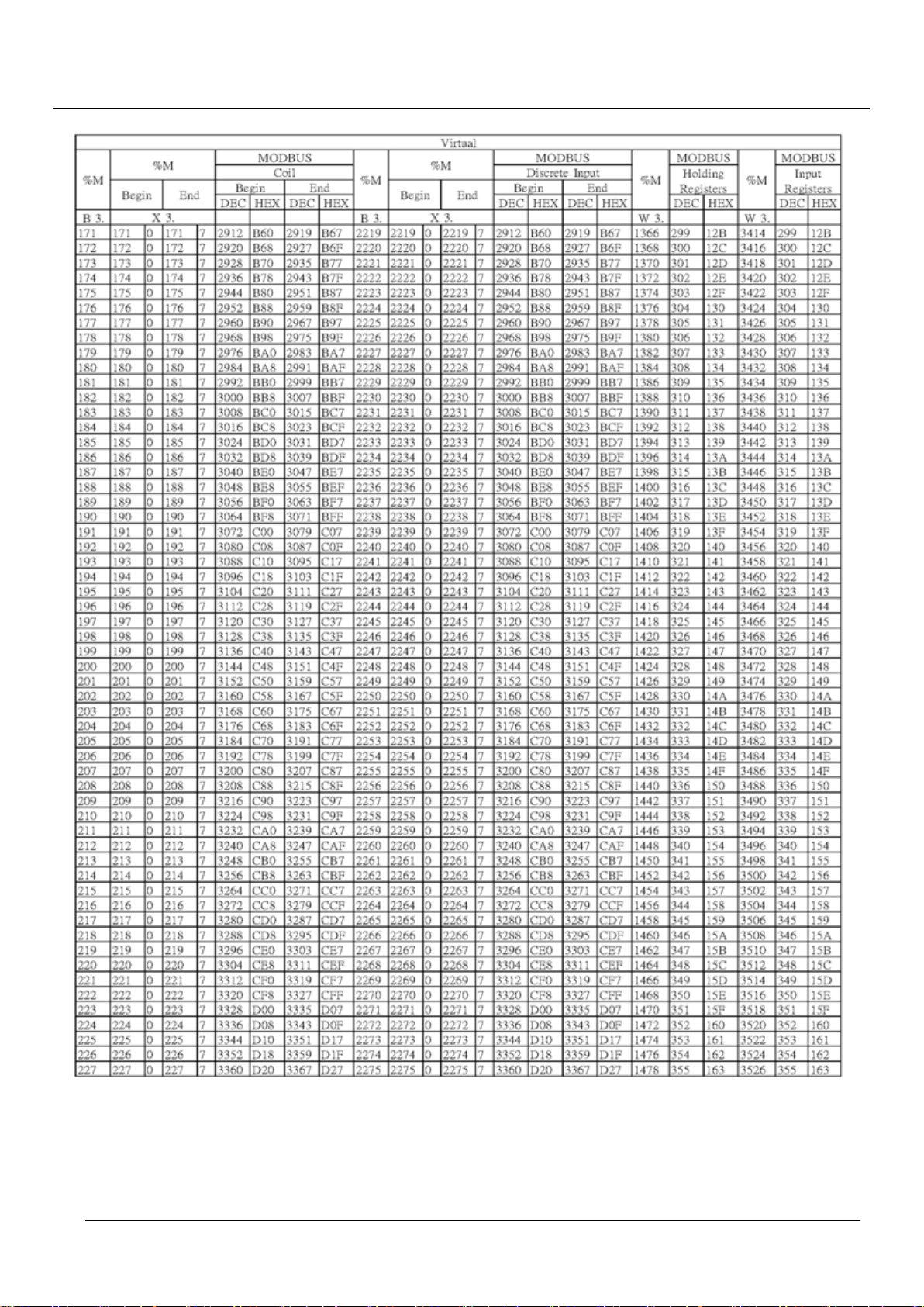
TPM
80
EasyPAC User Manual
Page 81
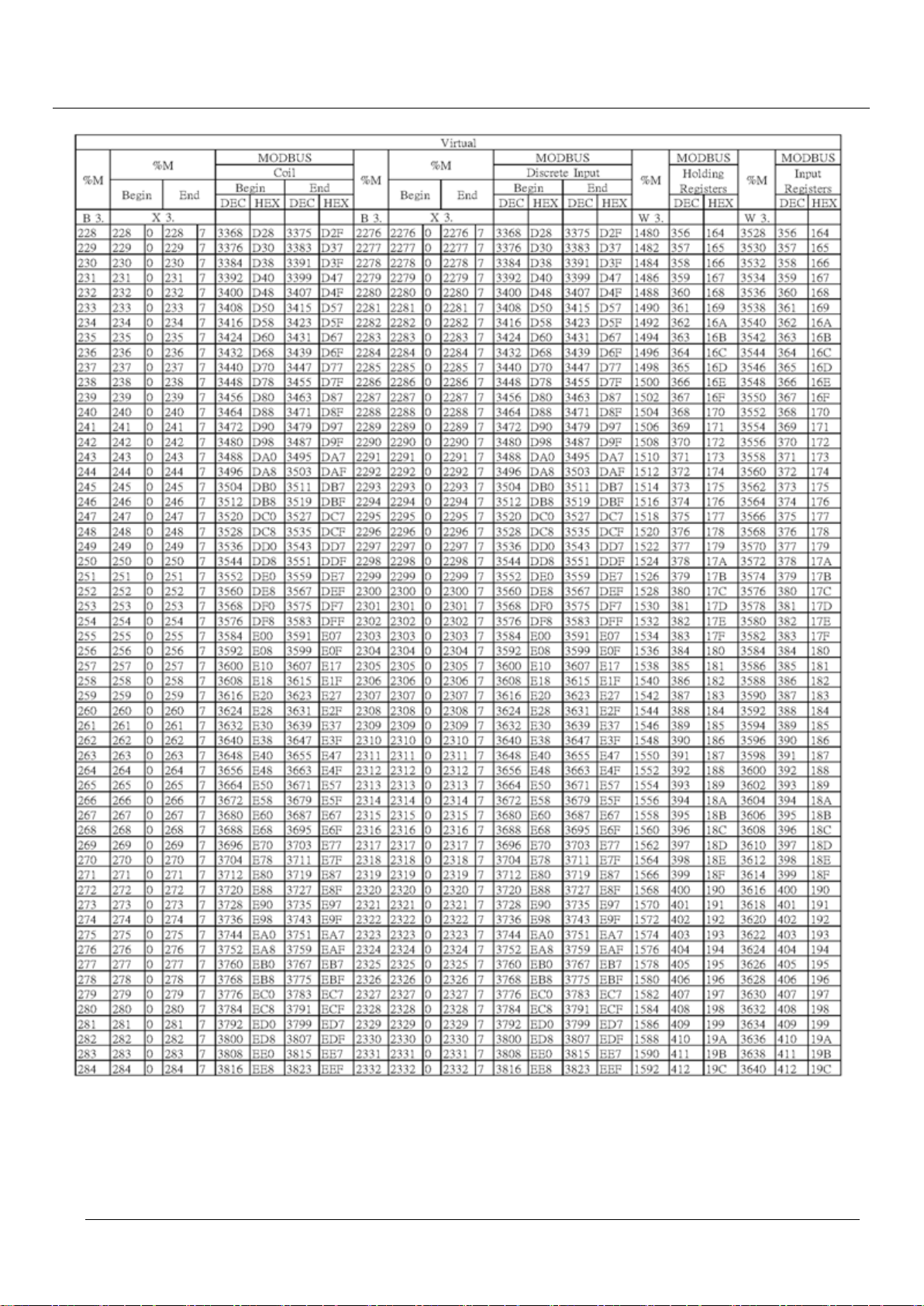
TPM
81
EasyPAC User Manual
Page 82
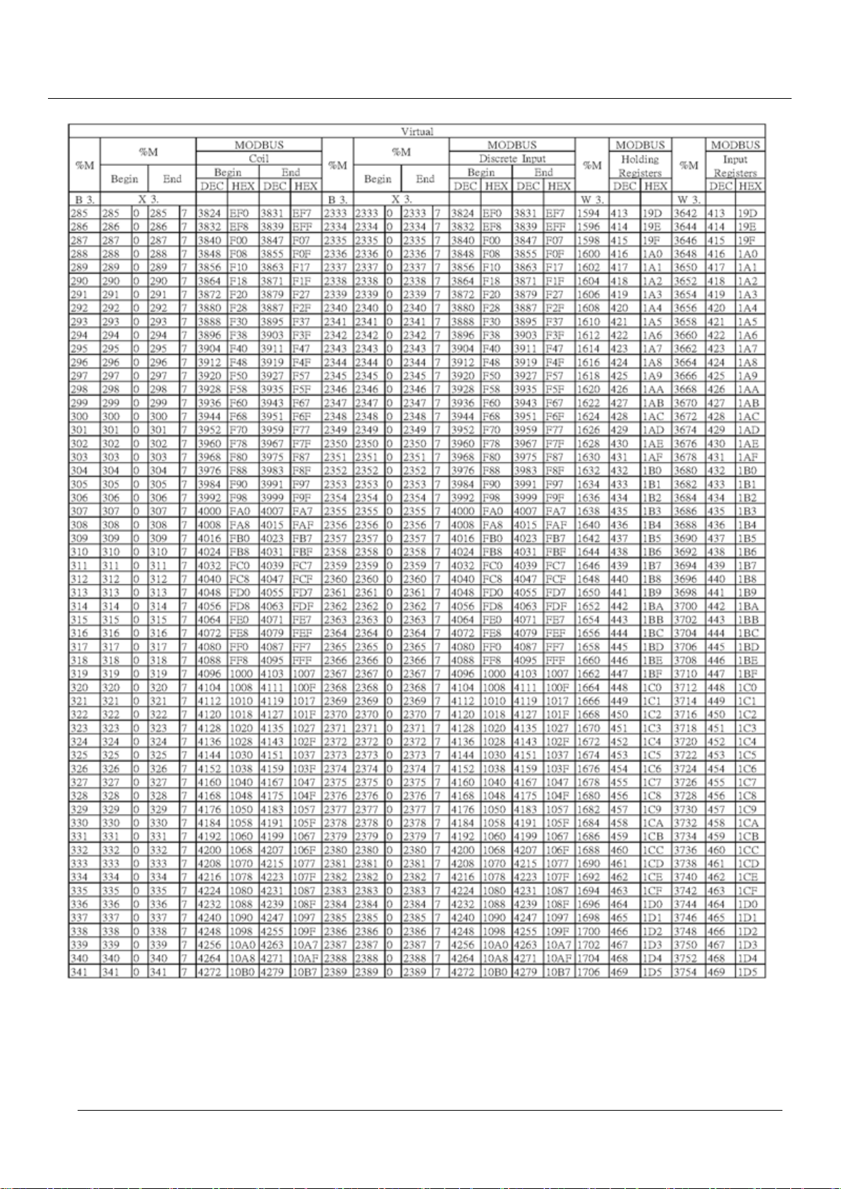
TPM
82
EasyPAC User Manual
Page 83
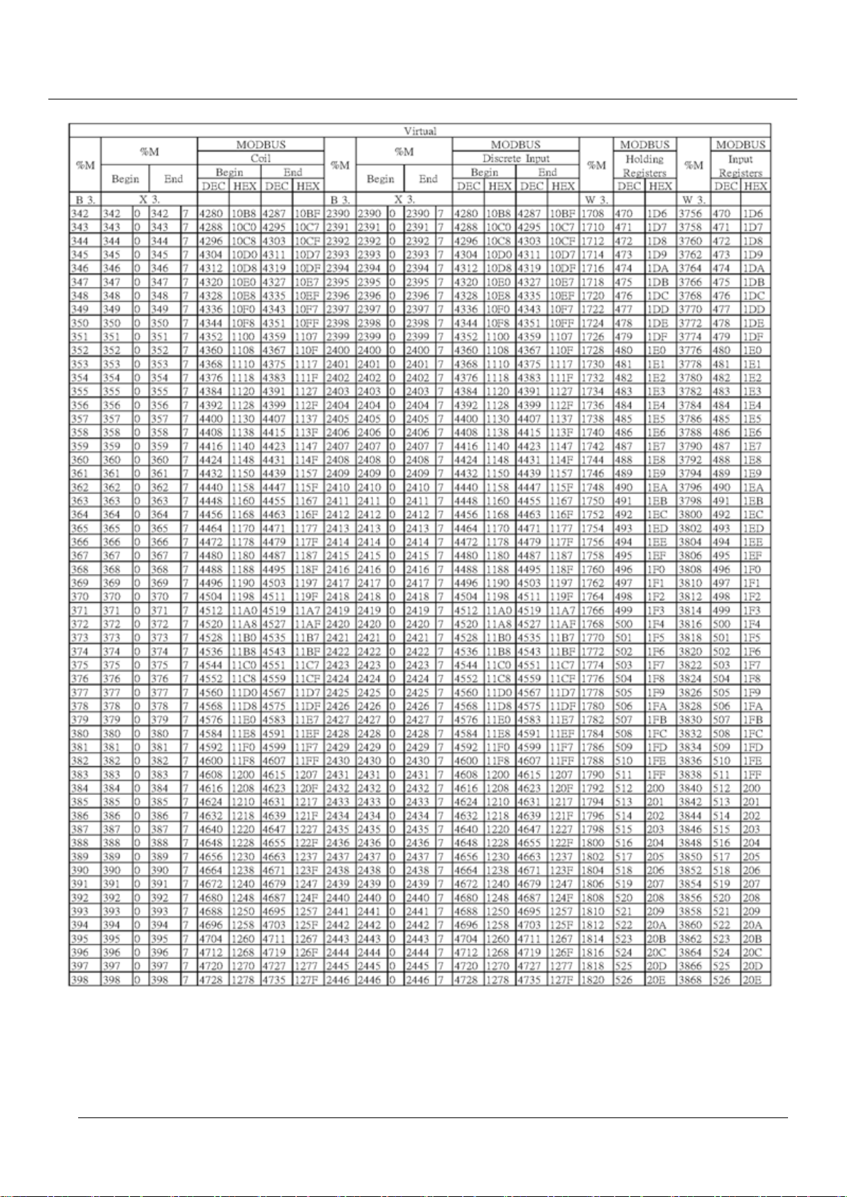
TPM
83
EasyPAC User Manual
Page 84
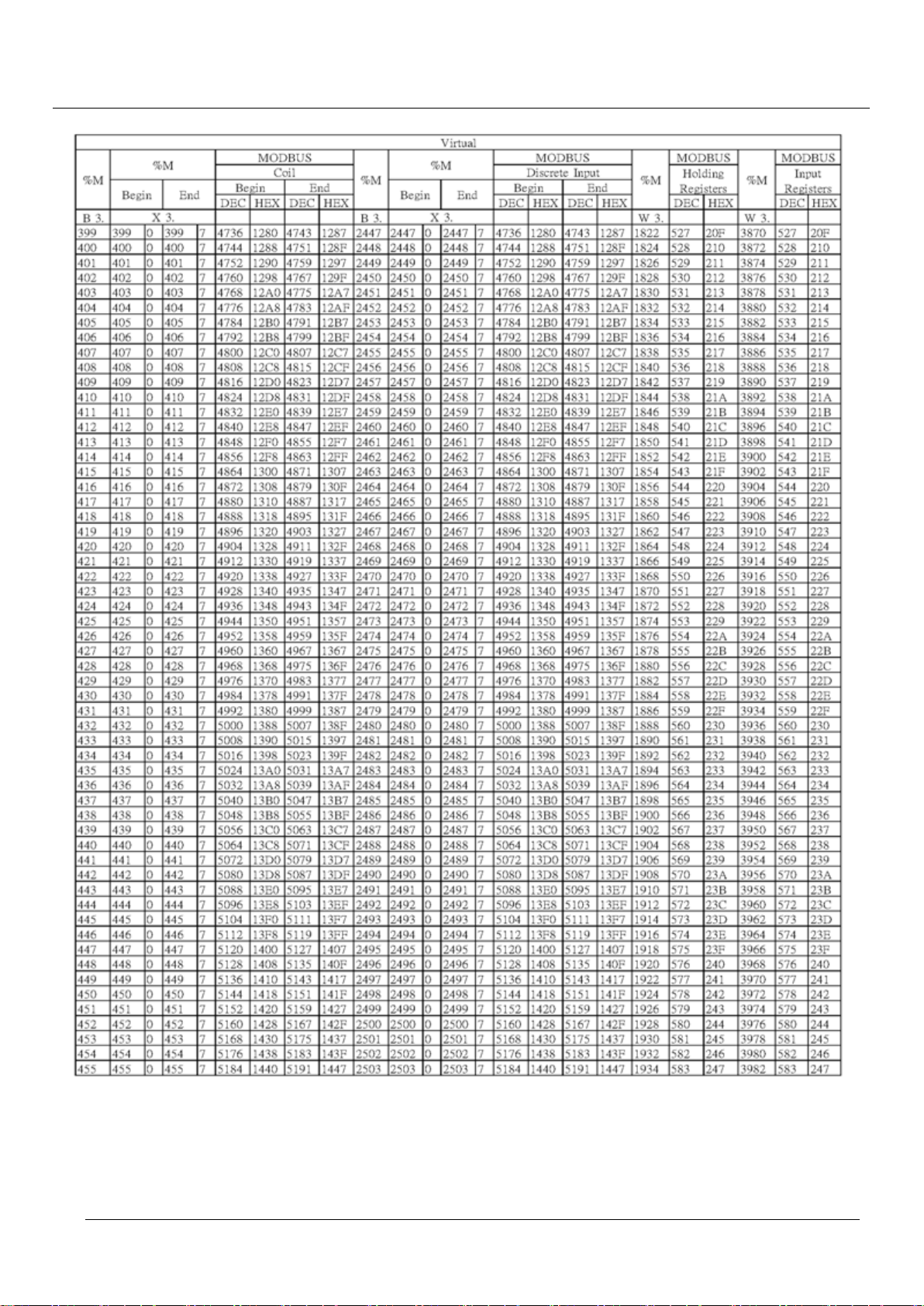
TPM
84
EasyPAC User Manual
Page 85
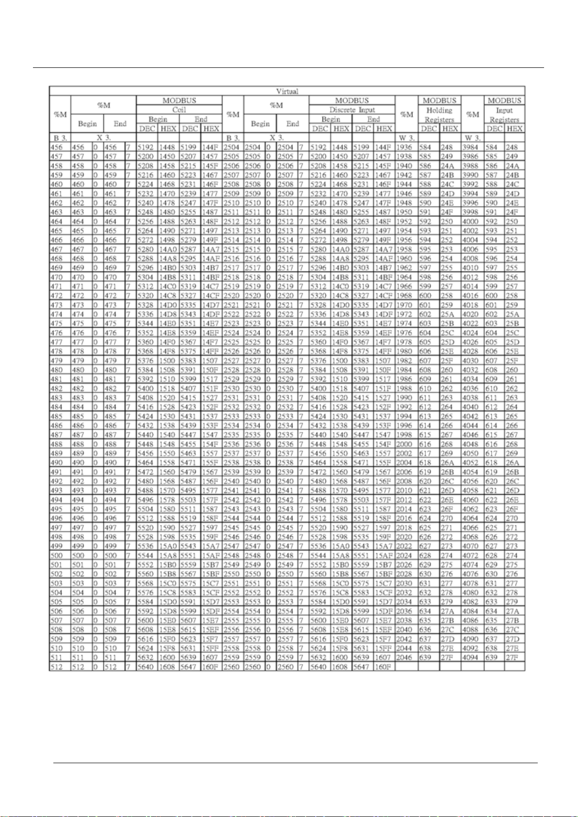
TPM
85
EasyPAC User Manual
Page 86
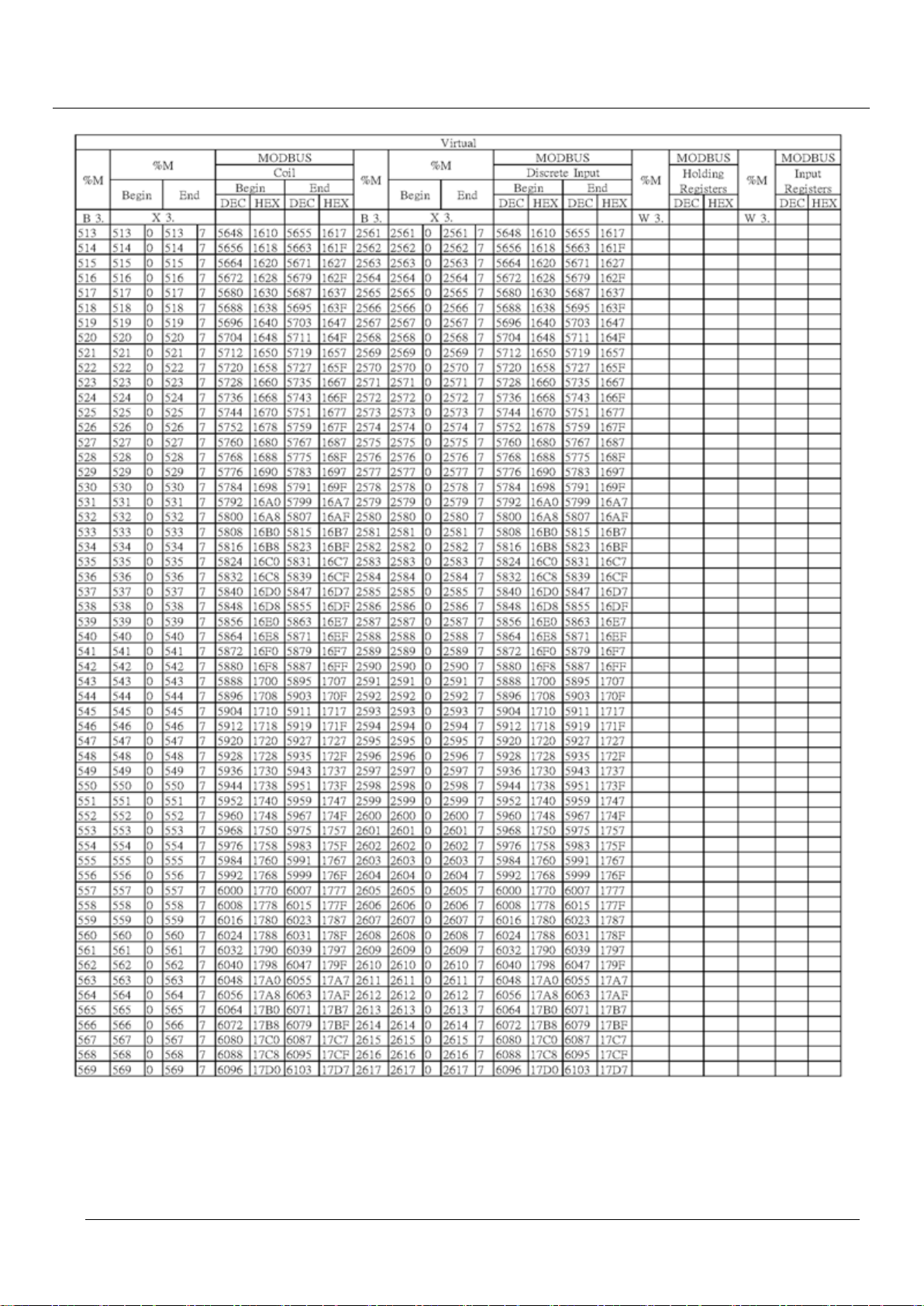
TPM
86
EasyPAC User Manual
Page 87
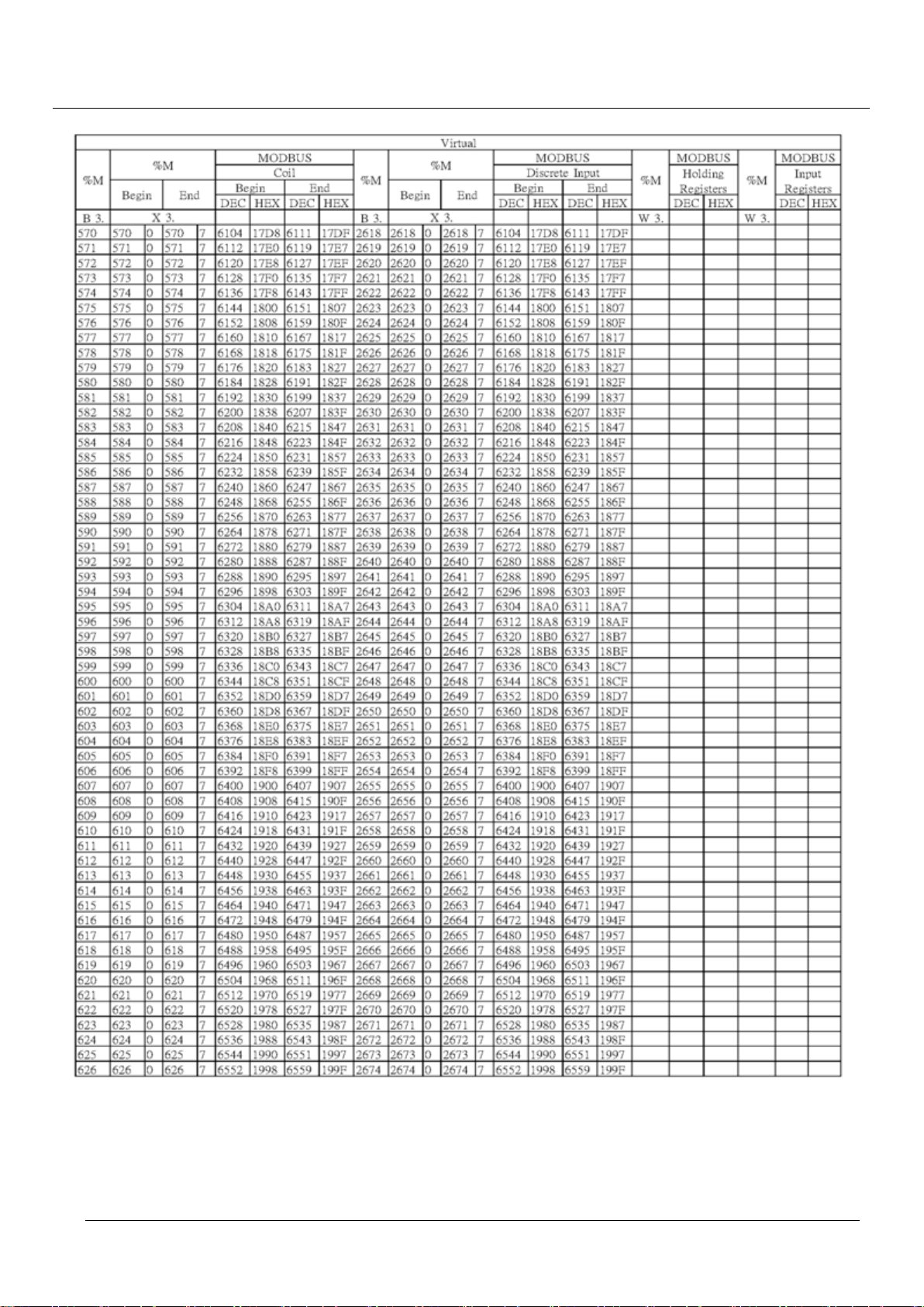
TPM
87
EasyPAC User Manual
Page 88
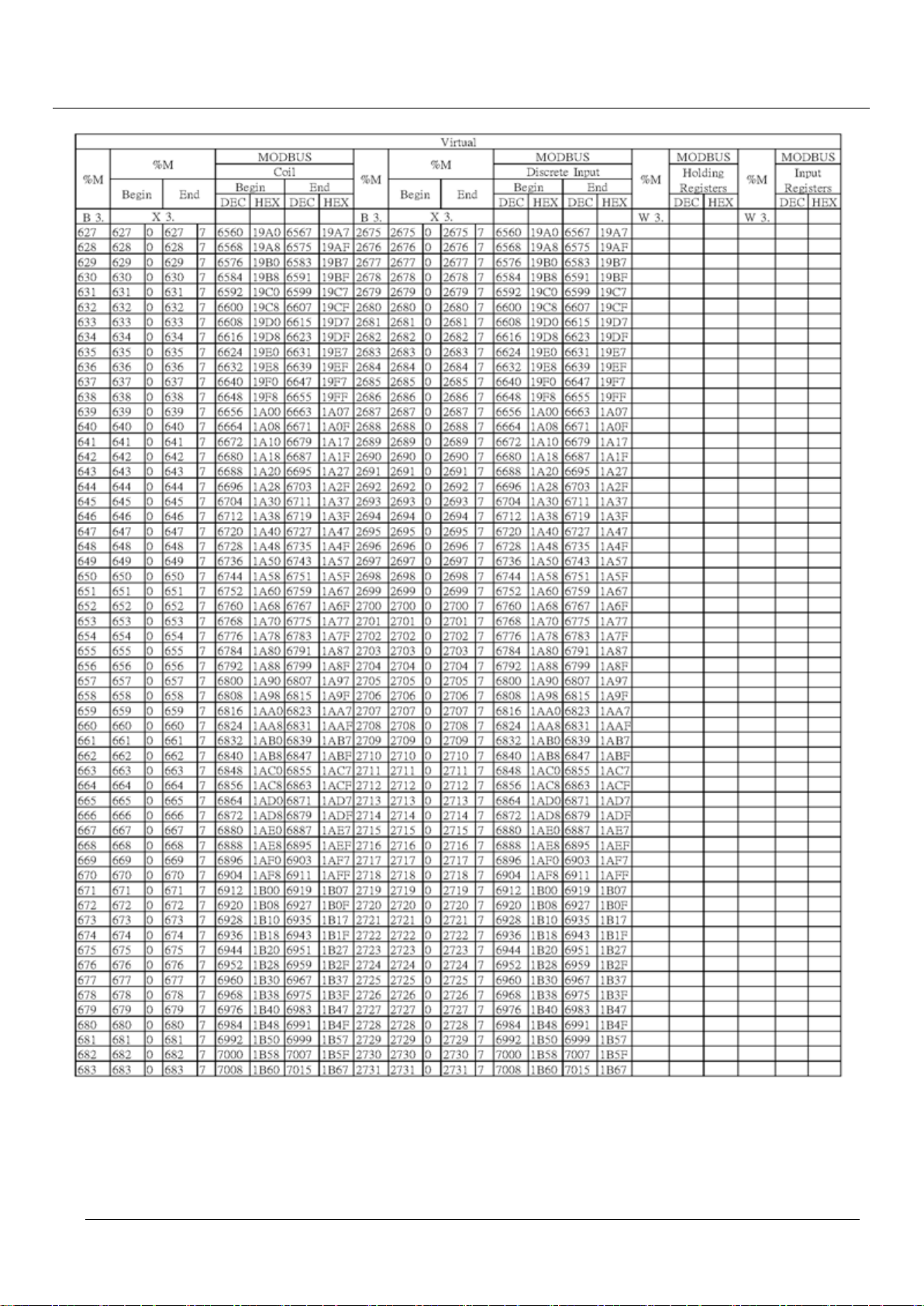
TPM
88
EasyPAC User Manual
Page 89
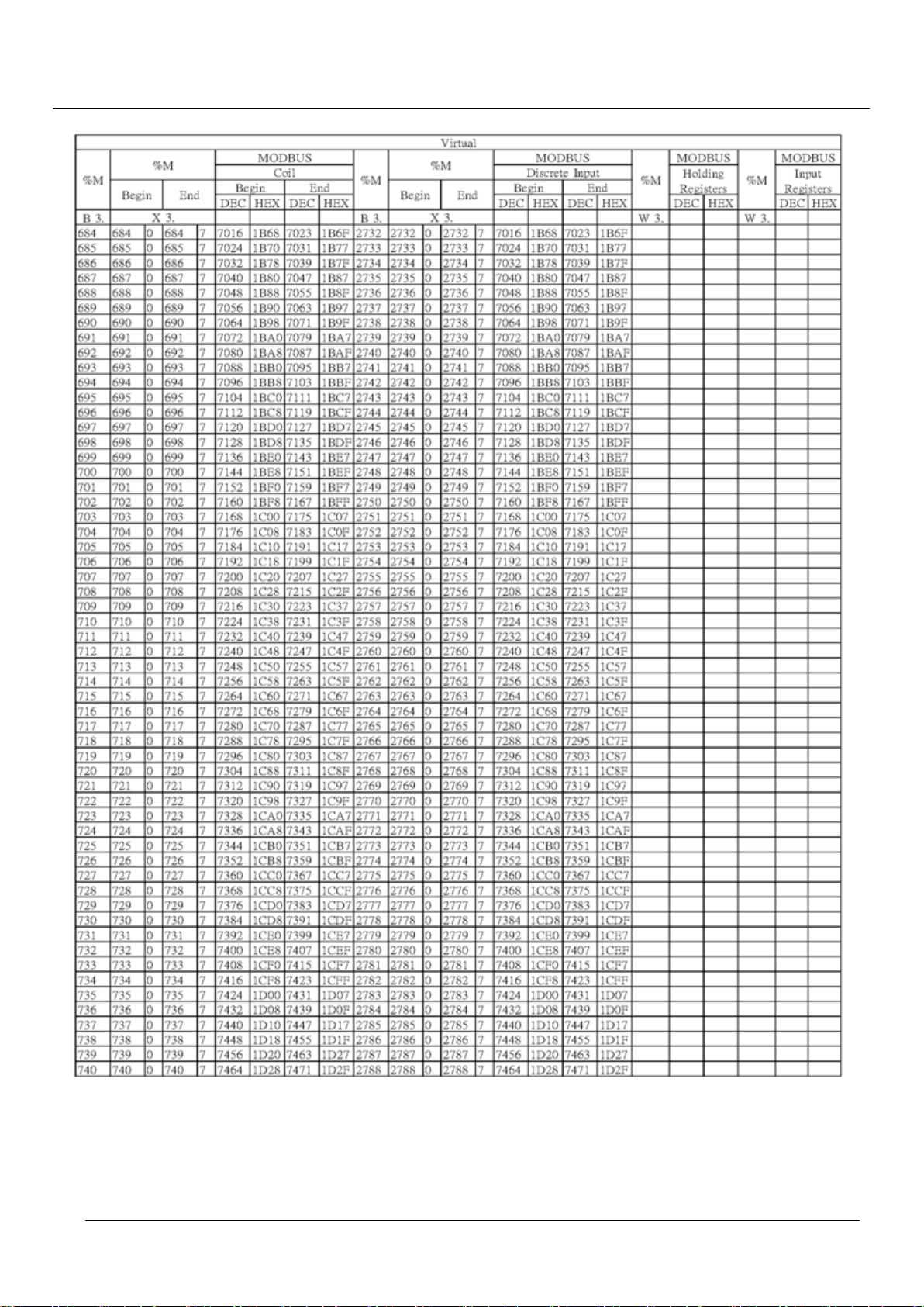
TPM
89
EasyPAC User Manual
Page 90
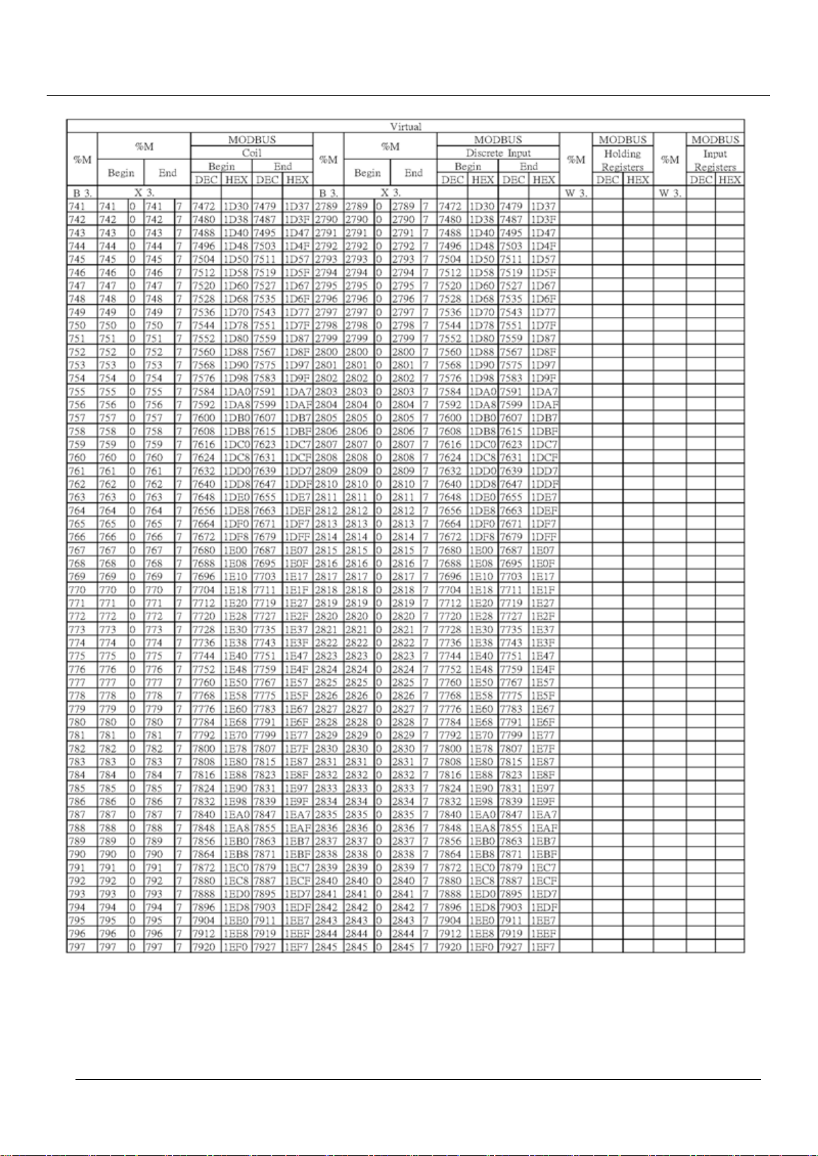
TPM
90
EasyPAC User Manual
Page 91
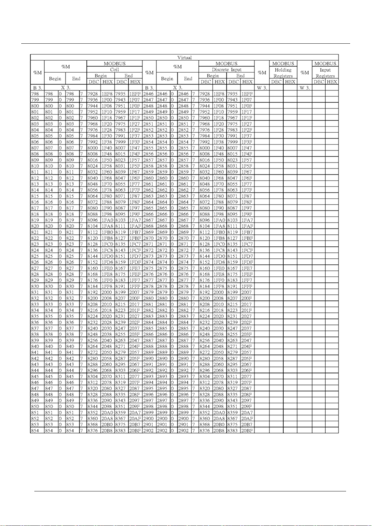
TPM
91
EasyPAC User Manual
Page 92
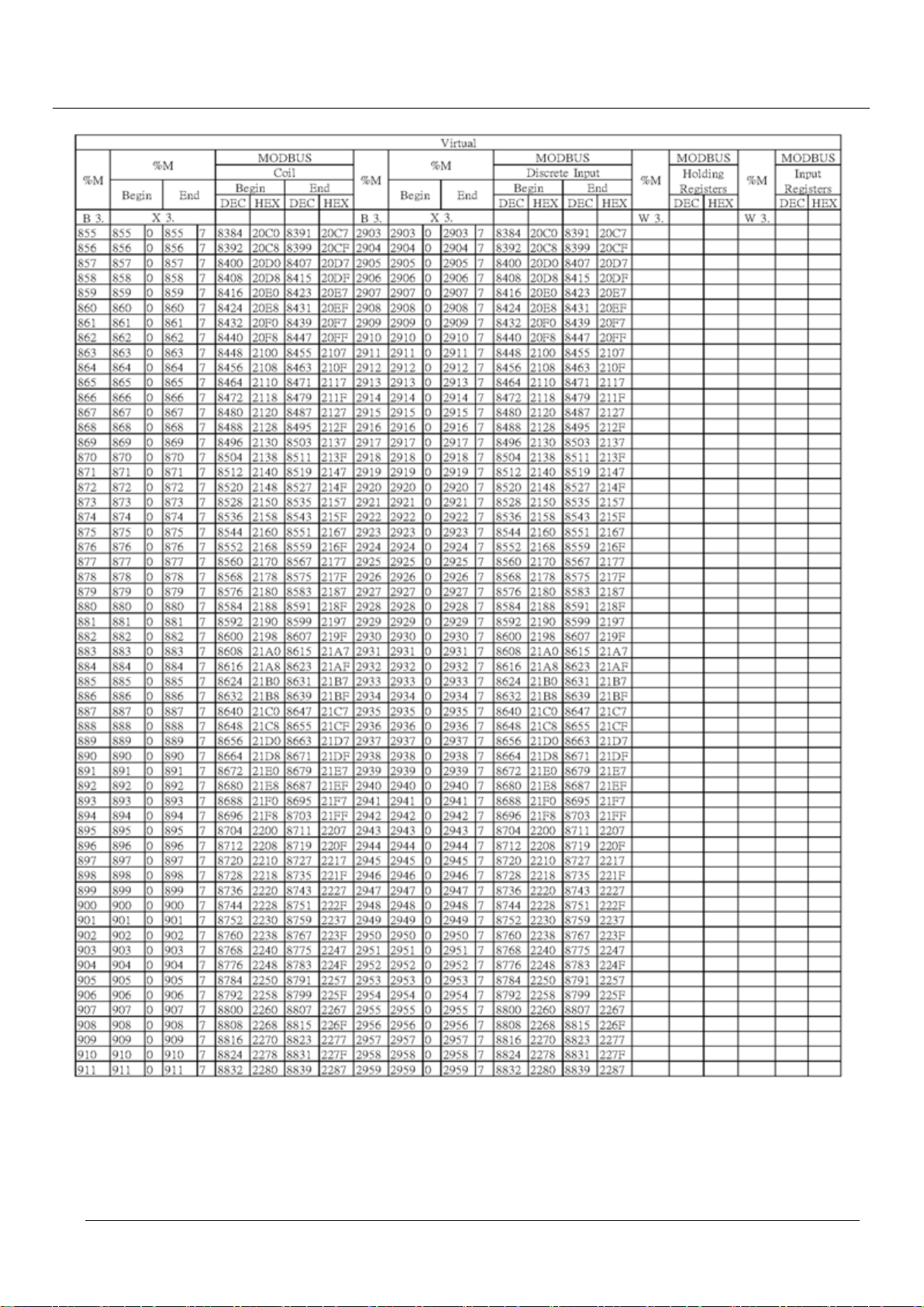
TPM
92
EasyPAC User Manual
Page 93
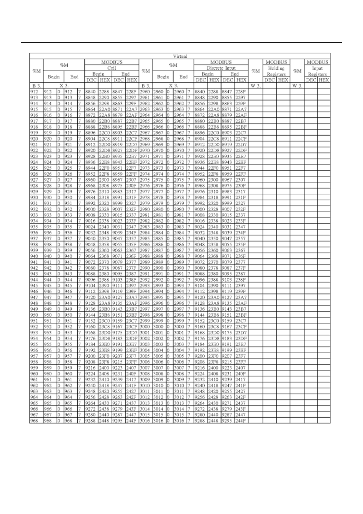
TPM
93
EasyPAC User Manual
Page 94
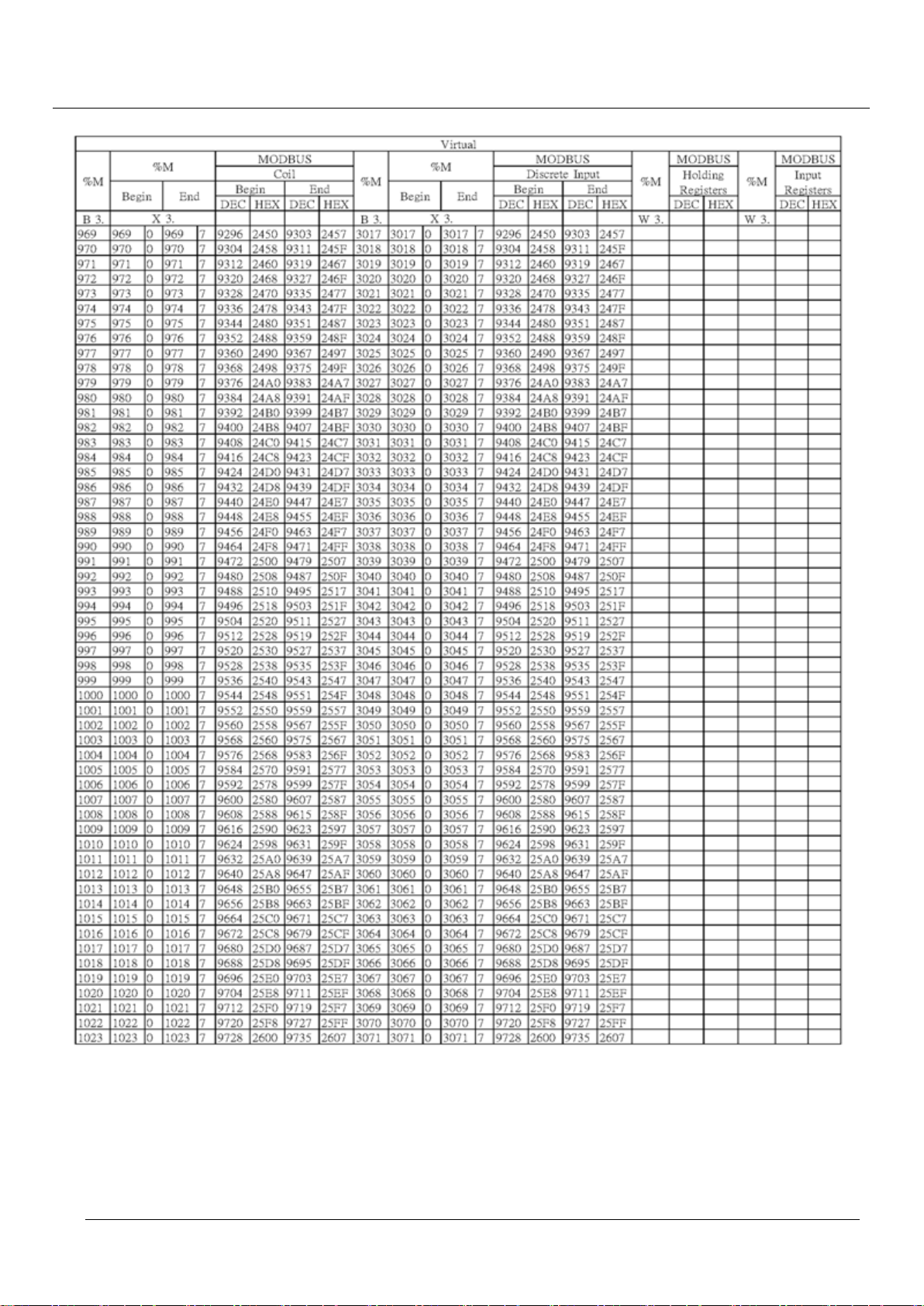
TPM
94
EasyPAC User Manual
Page 95
TPM
95
EasyPAC User Manual
6. MULTIPROG Introductions
MULTIPROG is an IEC-61131 Programming System developed by KW and MULTIPROG Express
5.35
is a compact version to be used with EasyPAC. The main features of MP Express 5.35 are
No. of IO per project 128 KB
No. of User Task 5
No. of POU’s 256
Global Variables 5000
Local Variables per POU 1500
Languages Support 5
MP Express 5.35 supports the following languages:
Textual Language
Instruction List (IL)
Structured Text (ST)
Graphical Language
Function Block Diagram (FBD)
Ladder Diagram (LD)
Sequential Function Chart (SFC)
MP Express 5.35 supports the following data types:
X is bit operation
B is byte operation
W is word operation
D is double word operation
%I is Input symbol
%Q is Output symbol
%M is Virtual symbol
Example
%IX1.7 The 7th bit in 1st Byte at input data, must be BOOL type
%IB100 The 100th Byte at input data, must be SINT / USINT / BYTE type
%QW201 The 201th, 202th Bytes at output data, must be INT / UINT / WORD type
%QL100 The 100th to 107th Bytes at output data, must be LREAL type
%MD3.1024 The 1024th to 1027th Bytes at virtual memory
Must be DINT / UDINT / REAL / TIME / DWORD type
Page 96
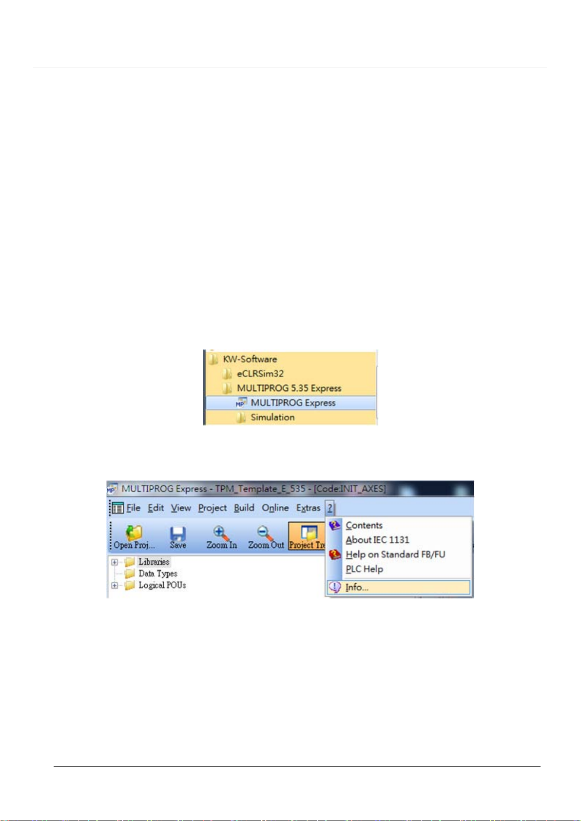
TPM
96
6.1. MPExpress5.35 installation
Recommended Hardware Requirement
PC Hardware: PC or laptop with Intel Centrino up CPU
Memory: 1GB RAM
OS: Windows 2000/XP/Win7 (32, 64)
LAN card: RJ-45 10/100/1000 Mbps
Software Installation
Install EasyPAC software and tools
Install MULTIPROG 5.35.252 Express
Install MULTIPROG Patch Files
Software Version
Run the successfully installed MULTIPROG 5.35 Express as shown below
EasyPAC User Manual
Figure 6-1: installed MULTIPROG Expre ss
Make sure the software version by the following figure illustrates.
Figure 6-2: figure out the software version info
If the software version is not 5.35 Build 252, please install the correct version.
Page 97
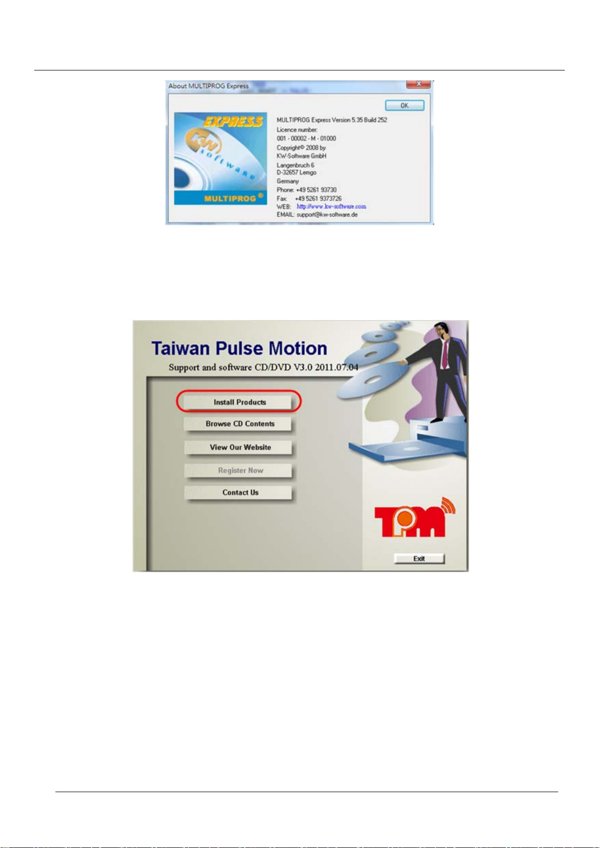
TPM
97
EasyPAC User Manual
Figure 6-3: the software version window
There is a CD that is shipped together with the EasyPAC. Please follow these steps below to finish the
installation. Insert the CD into your PC and you will be asked to permit auto-installation. Pleas e e nte r YES to
allow auto-installation as shown.
Figure 6-4: install product CD
If the auto-installation does not work, please try it manually. Please go to Program Manager and run the
Auto.exe in the CD to start installation manually. Users could click on “Install Products” as shown below to
setup EasyPAC.
Page 98
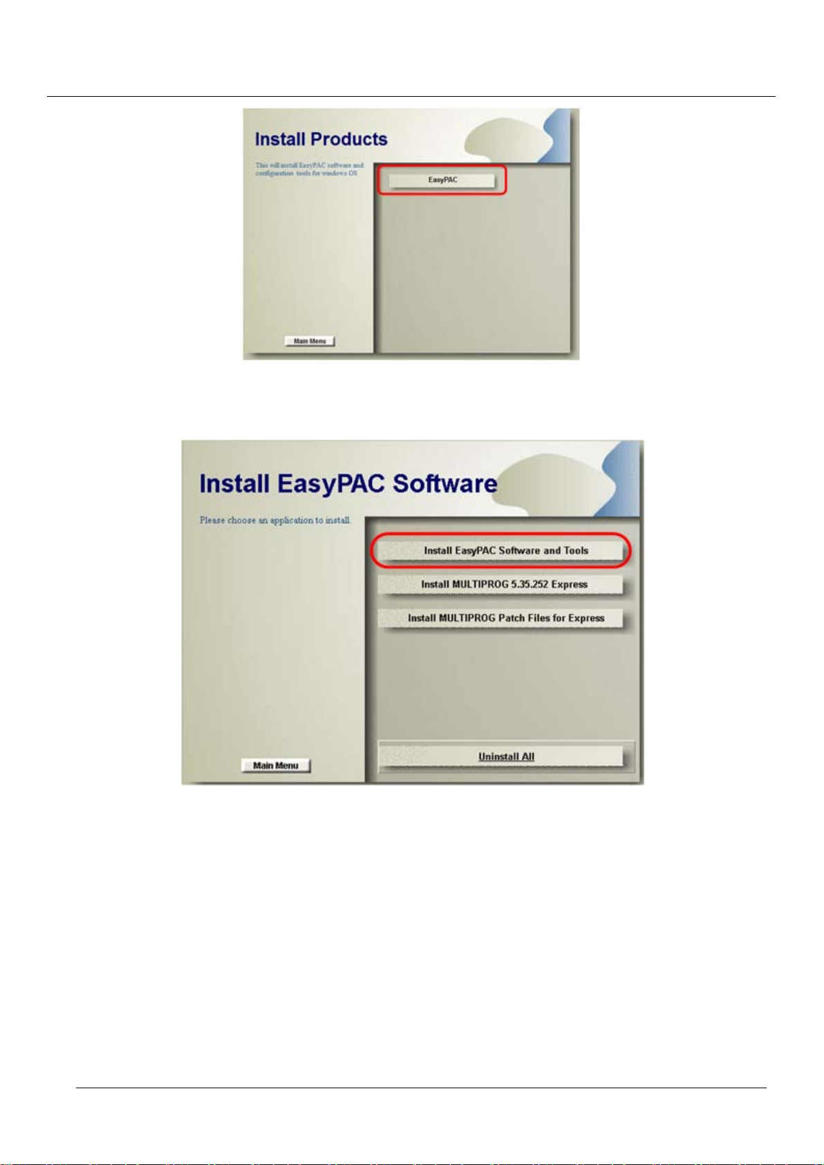
TPM
98
EasyPAC User Manual
Figure 6-5: procedure to setup EasyPAC
Press option “Install EasyPAC Software and Tools” to start setup EasyPAC related software and utilities.
Figure 6-6: install the correct utilities f or EasyPAC
Page 99
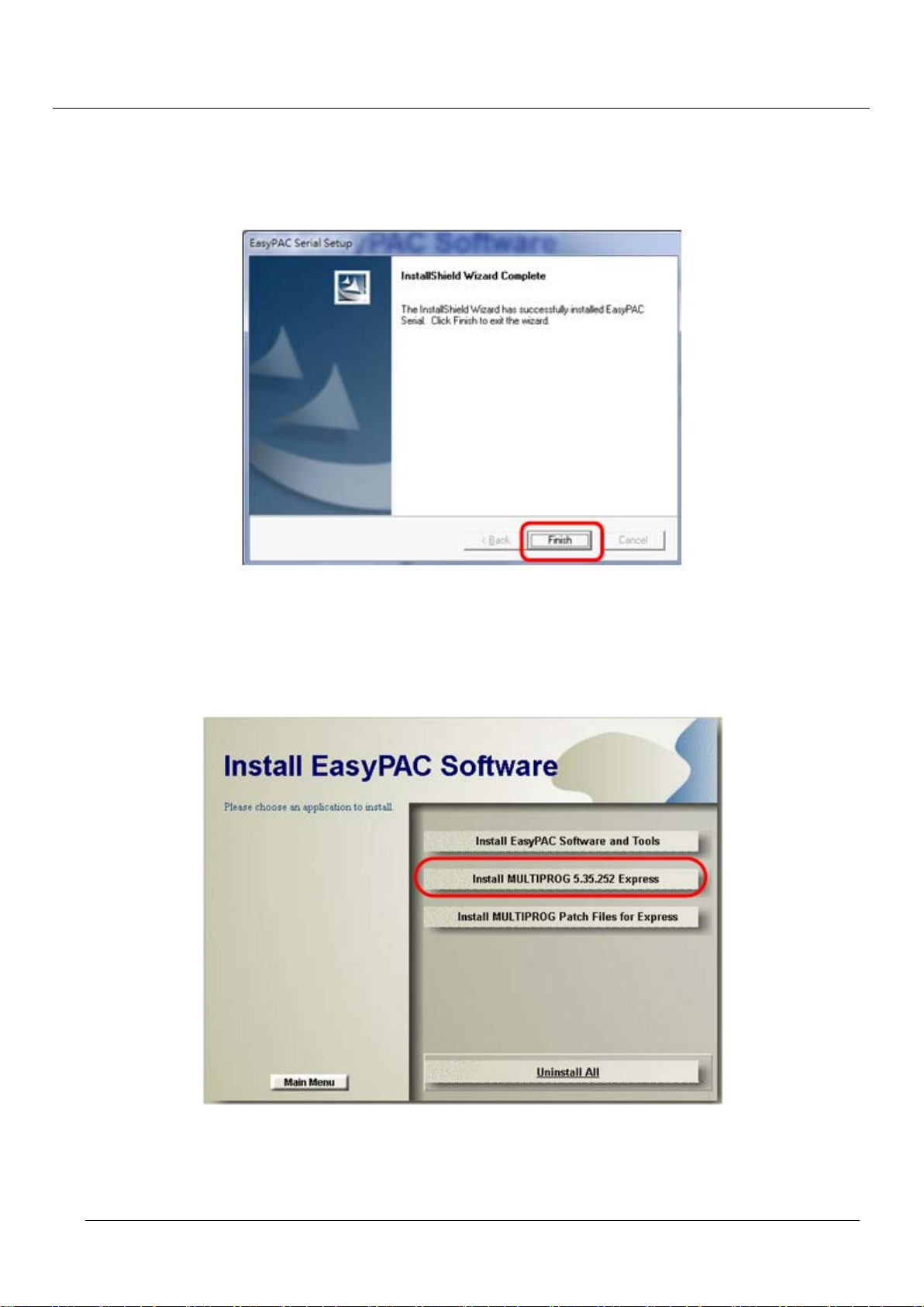
TPM
99
EasyPAC User Manual
6.1.1. Install EasyPAC Software and Tools
The default installation location is C:\TPM\EasyPAC. It is easy to complete the installation by click on the
“Finish” button as shown below.
Figure 6-7: click Finish button to complete the installation
6.1.2. Install MULTIPROG 5.35.252 Express
Please press the “Install MULT IPROG 5.35.252 Express” button to install the software.
Figure 6-8: install MULTIPROG
The installation procedure leads to install the relative libraries of MULTIPROG 5.35.252 Express and
software development kit for KW applications. The default location for the installation is C:\Program
Page 100
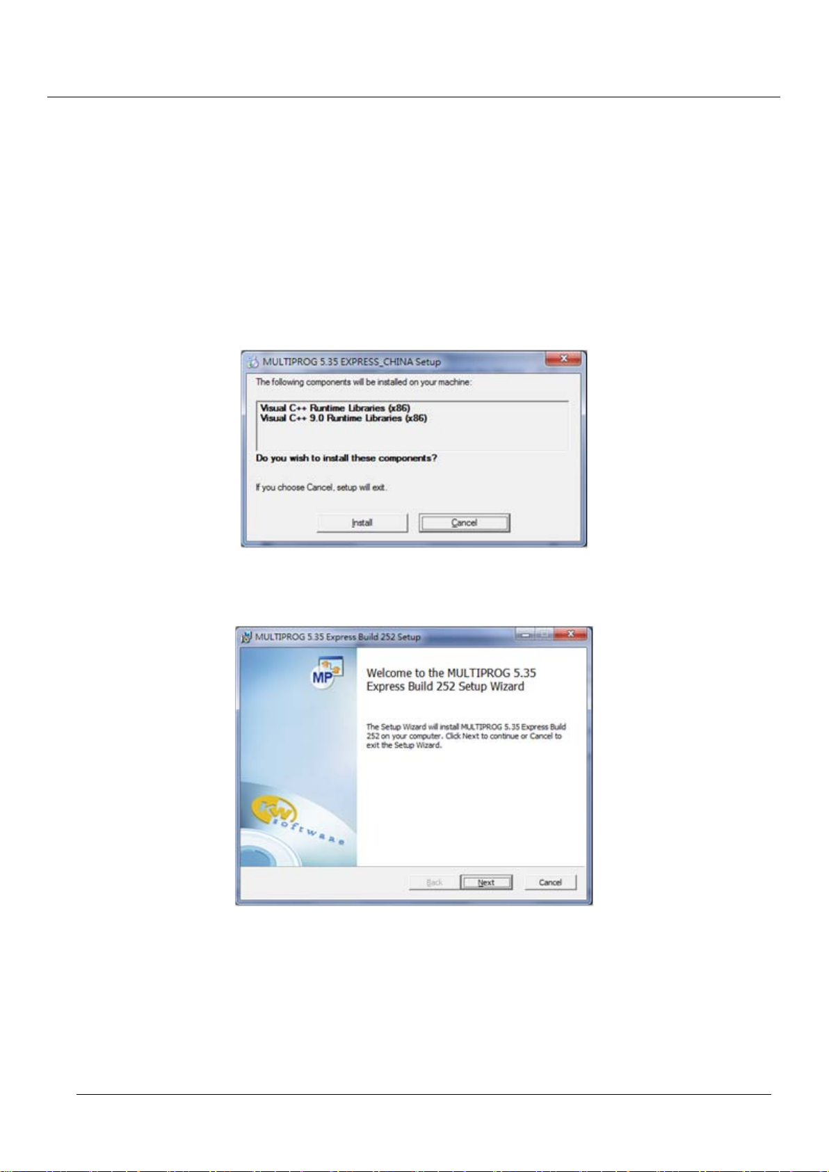
TPM
100
EasyPAC User Manual
Files\KW-Software. If the operating system is Windows 7 64bit, the location would be C:\Program Files
(86)\KW-Software. Please do not modify the default location in case of patch failure hereafter. The
installation procedure installs the following software in sequence.
MICROSOFT Visual C++ 2005 runtime libraries
MICROSOFT Visual C++ 2008 runtime libraries
MULTIPROG 5.35.252 Express Build 252
MULTIPROG ProConOS AddOn
The first step of the installation is a prompt of installation of MICROSOFT Visual C++ 2005/2008 runtime
libraries. Please select “Install” to start the installation.
Figure 6-9: installation of MICROSOFT Visual C++ 2005/2008 runtime libraries
The setup wizard will lead users to complete the rest of the installation.
Figure 6-10: screenshot of the setup wizard
Please check the “I accept the terms of …” option to carry on.
 Loading...