

Page 1

© 2017 TP-Link 7106507671 REV2.0.2
Installation Guide
JetStream 10-Gigabit 2-Port SFP+ Module
TX432
Page 2
Chapter 1 Introduction
1.1 Overview of the Product
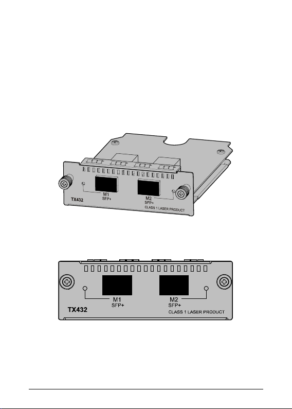
JetStream 10-Gigabit 2-Port SFP+ Module TX432 is an
interface card providing two 10G SFP+ ports. It is applicable to
multiple TP-Link switch models.
Figure 1-1 Appearance of TX432
Figure 1-2 Front panel of TX432
1
Page 3
Max
distance
optical fiber
optical fiber
9/125μm
optical fiber
TXC432-CU1M
1m
TXC432-CU3M
3m
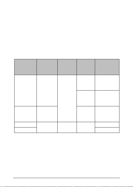
1.2 Description of Ports
Ports of TX432 are both 10G SFP+ ports. You can insert an
SFP+ transceiver into the port (on TX432) to connect it to the
SFP+ port (on another device) through an optical fiber, or an
SFP+ cable provided by TP-Link. For details about the
supported SFP+ transceivers and SFP+ cables, please refer to
the table below.
Transceiver
/Cable
TXM431-SR 850nm
TXM431-LR 1310nm
Central
wavelength
- - SFP+ cable
Connector
LC
Interface
cable
50/125μm
multimode
62.5/125um
multimode
single-mode
transmission
300m
33m
10km
2
Page 4

LED
Status
Description
Off
The port isn’t connected to any devices.
On
SPF+ port is connected to a device.
SPF+ port is connected to a device and
transferring data.
1.3 Description of LEDs
There is an LED for each port, labeled as M1 and M2, on the
panel of TX432. Described below:
M1,M2
Blinking
Note:
The switch applicable to TX432 will display corresponding
LEDs on its front panel to indicate the port status of the
interface card. For details about the LEDs, please refer to the
switch user guide.
Chapter 2 Installation
2.1 Tools for installation
• Philips screwdriver
• ESD-preventive wrist strap
2.2 Installing & Removing the Interface Card
• Installing the Interface Card to the switch
1. Wear an ESD-preventive wrist strap, and make sure that
it has good skin contact and is well grounded.
2. Use a Phillips screwdriver to loosen the mounting
screws of the filler panel on the interface card slot of the
3
Page 5

switch (T3700G-28TQ for example) and remove the filler
panel, as shown in Figure 2-1.
Figure 2-1 Install an interface card (1)
3. Hold the fastening screws on the front panel of the
interface card, and gently push the interface card in
along the slot guide rail until the interface card is flush
with the switch, as shown in Figure 2-2.
Figure 2-2 Install an interface card (2)
4. Tighten the captive screws with a Phillips screwdriver to
fix the interface card in place.
4
Page 6

• Removing the Interface Card
1. Wear an ESD-preventive wrist strap, and make sure that
it has good skin contact and is well grounded.
2. Use a Phillips screwdriver to loosen the captive screws
at both sides of the interface card until all spring
pressure is released.
3. Pull the interface card towards you along the guide rails,
until it completely comes out of the switch chassis.
Note:
• TX432 supports hot plug, so if necessary you can install
or remove the interface card when the switch is
operating. However, it is recommended that the power
be turned off during installation.
• Do not touch the surface-mounted components directly
with your hand while the switch is in operation.
• After removing an interface card, if no new interface
card is to be installed, please install the filler panel as
soon as possible to prevent dust from entering and
ensure the normal ventilation in the switch.
2.3 Verifying the Installation
The switch applicable to TX432 will display corresponding
LEDs on its front panel to indicate the port status of the
interface card. When the switch runs properly, check whether
the interface card is operating properly according to the
5
Page 7

status of its Port LED. If the interface card isn’t operating
properly, check whether it is installed correctly.
2.4 Safety of Laser Use
TX432 is a Class-1 laser device.
Do not look straight at the optical port of TX432 when it is
operating, because the optical fiber beam is of high energy
and thus will do great harm to the retina.
Looking straight at the optical fiber beam could do
great harm to your eyes.
6
Page 8

Normal
IEEE 802.3ae, IEEE 802.3aq,
SFF-8431
Safety & Emissions
FCC, CE
Max Power
Consumption
LED
M1,M2
Operating Temp
Storage Temp
Operating Humidity
10% to 90% RH, Non-condensing
Storage Humidity
5% to 90% RH, Non-condensing
For technical support and other information,
simply scan the QR code.
Appendix: Specifications
Standards
6.57w with Fiber
0℃ to 50℃ (32℉ to 122℉)
-40℃ to 70℃ (-40℉ to 158℉)
please visit http://www.tp-link.com/support, or
7
Page 9

FCC STATEMENT
This equipment has been tested and found to comply with the
limits for a Class A digital device, pursuant to part 15 of the
FCC Rules. These limits are designed to provide reasonable
protection against harmful interference when the equipment is
operated in a commercial environment. This equipment
generates, uses, and can radiate radio frequency energy and,
if not installed and used in accordance with the instruction
manual, may cause harmful interference to radio
communications. Operation of this equipment in a residential
area is likely to cause harmful interference in which case the
user will be required to correct the interference at his own
expense.
This device complies with part 15 of the FCC Rules. Operation
is subject to the following two conditions:
1) This device may not cause harmful interference.
2) This device must accept any interference received,
including interference that may cause undesired operation.
Any changes or modifications not expressly approved by the
party responsible for compliance could void the user’s
authority to operate the equipment.
Industry Canada Statement
CAN ICES-3 (A)/NMB-3(A)
Korea Warning Statements
당해 무선설비는 운용중 전파혼신 가능성이 있음.
Page 10

CE Mark Warning
This is a class A product. In a domestic environment, this
product may cause radio interference, in which case the user
may be required to take adequate measures.
Canadian Compliance Statement
This device complies with Industry Canada license-exempt
RSSs. Operation is subject to the following two conditions:
1) This device may not cause interference, and
2) This device must accept any interference, including
interference that may cause undesired operation of the
device.
Le présent appareil est conforme aux CNR d’Industrie Canada
applicables aux appareils radio exempts de licence.
L’exploitation est autorisée aux deux conditions suivantes :
1) l’appareil ne doit pas produire de brouillage;
2) l’utilisateur de l’appareil doit accepter tout brouillage
radioélectrique subi, meme si le brouillage est susceptible
d’en compromettre le fonctionnement.
BSMI Notice
安全諮詢及注意事項
請使用原裝電源供應器或只能按照本產品注明的電源類型使用本
產品。
Page 11

PBB
○ ○ ○ ○ ○ 外殼 ○ ○ ○ ○ ○ ○
1. "超出0.1 wt %" 及 "超出0.01 wt %" 系指限用物質之百分比含
含量基準值。
3. " − "
清潔本產品之前請先拔掉電源線。請勿使用液體、噴霧清潔劑或濕
布進行清潔。
注意防潮,請勿將水或其他液體潑灑到本產品上。
插槽與開口供通風使用,以確保本產品的操作可靠並防止過熱,請
勿堵塞或覆蓋開口。
請勿將本產品置放於靠近熱源的地方。除非有正常的通風,否則不
可放在密閉位置中。
請不要私自打開機殼,不要嘗試自行維修本產品,請由授權的專業
人士進行此項工作。
此為甲類資訊技術設備,于居住環境中使用時,可能會造成射頻擾動,
在此種情況下,使用者會被要求採取某些適當的對策。
限用物質含有情況標示聲明書
限用物質及其化學符號
產品元件名稱
PCB
備考
量超出百分比含量基準值。
備考 2. "○"
備考
鉛
Pb 鎘 Cd
○
系指該項限用物質之百分比含量未超出百分比
系指該項限用物質為排除項目。
汞
Hg
六價鉻
CrVI
多溴聯
苯
多溴二苯醚
PBDE
Продукт сертифіковано згідно с правилами системи
УкрСЕПРО на відповідність вимогам нормативних
документів та вимогам, що передбачені чинними
законодавчими актами України.
Page 12

Safety Information
Keep the device away from water, fire, humidity or hot
environments.
Do not attempt to disassemble, repair, or modify the device.
Do not use damaged charger or USB cable to charge the
device.
Do not use any other chargers than those recommended.
この装置は、クラスA情報技術装置です。この装置を家庭環境で使用
すると電波妨害を引き起こすことがあります。この場合には使用者
が適切な対策を講ずるよう要求されることがあります。
VCCI-A
EU declaration of conformity
TP-Link hereby declares that the device is in compliance with
the essential requirements and other relevant provisions of
directives 2014/30/EU, 2014/35/EU, 2009/125/EC and
2011/65/EU.
The original EU declaration of conformity may be found at
http://www.tp-link.com/en/ce
 Loading...