

Page 1

User Guide
2.4GHz 14dBi Directional Antenna
TL-ANT2414A
2.4GHz 9dBi Directional Antenna
TL-ANT2409A
2.4GHz 24dBi Grid Parabolic Antenna
TL-ANT2424B
7106507861 REV2.0.2
Page 2
TL-ANT2414A/ TL-ANT2409A
Electrical Specifications
Frequency Range
2.4GHz to 2.5GHz
Impedance
50Ω Nominal
Gain
TL-ANT2414A: 14dBi
TL-ANT2409A: 9dBi
VSWR
1.92 Max
Return Loss
-10dB Maximum
Radiation
Directional
Admitted Power
1W
Physical Specifications
Cable
CFD-200 Coaxial Cable
Antenna Cover
ABS
Operating Temp
-20℃ to 65℃
Storage Temp
-30℃ to 75℃
Color
Gray
Connector
RP-SMA Plug (male)
Specification
Page 3
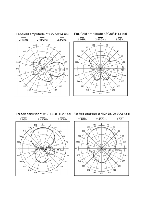
Field Pattern
TL-ANT2414A
TL-ANT2409A
Page 4

Installation
There are two methods to install the antenna: wall mounting
and pole mounting.
Note: For simplicity, we will take TL-ANT2409A for example
throughout the following introduction.
1. Wall Mounting
① Antenna 1 pc
② Holder 1 pc
③ Screws 4 pcs
④ Plastic Fixings 2 pcs
⑤ Sticker 1 pc
Page 5

2. Pole Mounting
① Antenna 1 pc
② Holder 1 pc
③ Screws 2 pcs
④ Hose Clamp 1 pc
Page 6

Specification
Electrical Specifications
Frequency Range
2.4GHz to 2.5GHz
Impedance
50Ω
Gain
24dBi
VSWR
≤1.5
Horizontal Beamwidth
14°
Vertical Beamwidth
10°
F/B Ratio
30dB
Polarization
Vertical or Horizontal
Maximum Input Power
100W
Connector
N Female
Application
Outdoor
Mount Style
Pole Mount / Wall Mount
Mechanical Specifications
Antenna Dimension
600×1000 mm
Weight
3.5 +/-0.15 KG
Mounting Mast Diameter
Ø30~Ø50 mm
Rated Wind Velocity
216 Km/h
TL-ANT2424B
>
Page 7

Installation
1. Assembly the two pieces of reflector symmetrically.
2. Mount the feed horn on the reflector according to the
Mounting diagram. Make sure the feed dipoles parallel with
most bars of the grid reflector. When the feed dipoles and
most grid bars are vertical to the ground, the antenna is
vertical polarized. When the feed dipole and most grid bars
are horizontal to the ground, the antenna is horizontal
polarized.
3. Mount the “L” type bracket at the back of the reflector, then
mount the antenna on the mast supplied by customer
according to the Mounting diagram.
Page 8

For technical support and other information,
simply scan the QR code.
4. Test the antenna with equipment to make sure the antenna
receive the best signal by turning the azimuth and pitching
angle, then lock all the screws and seal the connector
between antenna and cable.
please visit http://www.tp-link.com/support, or
©2017 TP-Link
 Loading...